Cisco Systems 60010030 802.11a/b/g/n Dual Radio User Manual
Cisco Systems 802.11a/b/g/n Dual Radio
User Manual
Meraki MR11/14
Hardware Installation Guide
2
Table of Contents
1 Scope of Document and Related Publications 7
2 MR14 Overview 8
2.1 Package Contents 8
2.2 Understanding the MR14 9
2.3 Power Source Options 11
2.4 Security Features 10
2.5 Factory Reset Button 11
2.6 LED Indicators and Run Dark Mode 11
2.7 UL 2043 Plenum rating 12
3 Pre-Site Preparation 13
3.1 Check and Upgrade Firmware 13
3.2 Collect Tools 13
3.3 Collect Additional Hardware for Installation 14
3.4 Configure Your Network in Dashboard 13
4 On Site Instructions 16
4.1 Choose Your Mounting Location 16
4.2 Install the MR14 16
4.2.1 Attach the Mount Plate 16
4.2.1.1 Wall or Solid Ceiling Mount Using Mount Plate 18
4.2.1.2 Drop Ceiling Mount Using Mount Plate 19
4.2.1.3 Electrical Junction Box Mount Using Mount Plate 22
4.2.2 Power the MR14 22
4.2.3 Mount the MR14 22
4.2.3.1 Assemble MR14 to the Mount Plate 22
4.2.3.2 Desk or Shelf Mount 24
4.2.3.3 Wall or Solid Ceiling Mount without Mount Plate 24
4.2.3.4 Plenum Mount (Above Dropped Ceiling) 25
4.3 Secure the MR14 26
4.4 Verify Device Functionality and Test Network Coverage 27
5 Troubleshooting 28
6 Regulatory Information 29
3
1 Scope of Document and Related Publications
The MR11/14 Hardware Installation Guide describes the installation procedure for
the MR11 and MR14 access point.
Note: All instructions in this hardware installation guide will reference the MR14 product
but apply equally to the MR11.
Additional reference documents are available online at www.meraki.com/library/products, including:
Meraki Network Design Guide – This document describes how to effectively design a Meraki wireless network.
Meraki Cloud Controller Manual – This document describes how to use the Meraki Cloud Controller to set
up and configure a Meraki network.
4
MR14 Access Point Mounting Plate T-rail Mounting Kit Wall Screws/Anchors
2 MR14 Overview
The Meraki MR14 is an enterprise-class 802.11n access point that enables you to create high-speed,
reliable wireless networks in even the most challenging RF environments quickly, easily and cost-effectively.
2.1 Package Contents
The MR14 package contains the following:
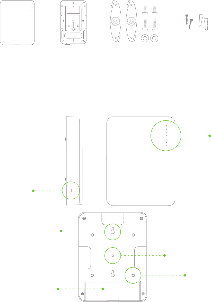
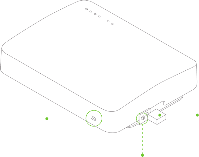
2.2 Understanding the MR14
Your Meraki MR14 has the following features:
Kensington lock
hard point
LED indicators
Mount plate attachment
Multi-purpose mounting hole
Desk mount Feet (4x)
Cable access bay
5
Factory reset button
Various mounting holes
(see p. 13-14 for details)
Security screw
Cable slot
Pad lock and security
screw holes
Cable slot
Ethernet port (with PoE)
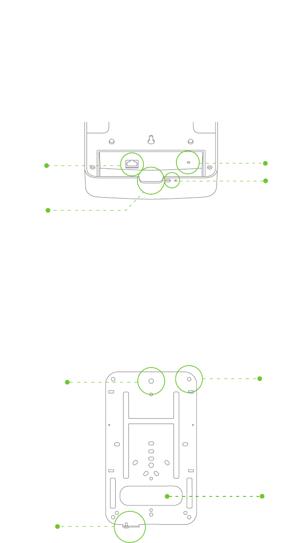
Your MR14 mount plate has the following features:
Access point
mounting post

6
2.3 Security Features
The MR14 features multiple options for physically securing the access point after installation:
1. Security screw – The mount plate contains a security screw that can be used to secure the access
point to the mount plate. Engaging the security screw prevents accidental dislodging and theft.
2. Pad lock – The access point and mount plate contain hard points to allow them to be locked together
using a Masterlock 120T or equivalent. Securing the MR14 with a pad lock provides an additional
level of theft protection.
3. Kensington lock – The access point contains a hard point that allows it to be secured to any nearby
permanent structure using a standard Kensington lock.
2.4 Power Source Options
The MR14 access point can be powered using either a third-party 802.3af PoE switch or the Meraki
802.3af PoE injector (sold separately).
2.5 Factory Reset Button
The Factory Reset Button restores the MR14 to its original factory settings by deleting all configuration
information stored on the unit.
2.6 LED Indicators and Run Dark Mode
Your MR11 is equipped with a series of LED lights on the front of the unit to convey information
about system functionality and performance.
Signal Strength
1 Light: Fair, 4 Lights: Strongest
Moving Lights: Searching for Signal
Flashing Lights: Error state. May indicate bad gateway or other routing fault
Radio Power
Off: MR14 is off
Solid ORANGE: MR14 is booting or trying to find a path to the internet
Solid GREEN: MR14 is fully operational and connected to the network
Flashing ORANGE: Firmware is upgrading
Flashing GREEN: Error state. May indicate bad gateway or other routing fault
Ethernet
Off: No active network connection at the Ethernet port
On: Active network connection at the Ethernet port
Flashing: Error state. May indicate bad gateway or other routing fault
The MR14 may be operated in “Run Dark” mode for additional security and to reduce the visibility
of the access point. In this mode, the LEDs will not be illuminated. This mode may be enabled
through the Meraki Dashboard.
2.7 UL 2043 Plenum rating
The MR14 meets the UL 2043 plenum-rating standard. This certifies that the MR14 has adequate
fire resistance and low smoke-emission characteristics to be mounted and operated in a building’s
environmental air spaces, such as above suspended ceilings in an office environment.
7
3 Pre-Install Preparation
You should complete the following steps before going on-site to perform and installation.
3.1 Configure Your Network in Dashboard
The following is a brief overview only of the steps required to add an MR14 to your network. For detailed
instructions about creating, configuring and managing Meraki wireless networks, refer to the Meraki
Hosted Controller Manual (meraki.com/collateral).
1. Login to http://dashboard.meraki.com. If this is your first time, create a new account
2. Find the network to which you plan to add your nodes or create a new network.
3. Add your nodes to your network. You will need your Meraki order number (found on your invoice if you
ordered directly from Meraki) or the serial number of each node, which looks like Qxxx-xxxx-xxxx, and is
found on the bottom of the unit.
4. Finally, go to the map / floor plan view and place each node on the map by clicking and dragging it to
the location where you plan to mount it. You can always modify the location later.
3.2 Check and Upgrade Firmware
To ensure your MR14 performs optimally immediately following installation, Meraki recommends that you
facilitate a firmware upgrade prior to mounting your MR14.
1. Attach your MR14 to power and a wired Internet connection. See p. 19 of this Hardware Installation
Guide for details.
2. The MR14 will turn on and the Power LED will glow solid orange. If the unit does not require a firmware
upgrade, the Power LED will turn green within thirty seconds.
* If the unit requires an upgrade, the Power LED will begin blinking orange until the upgrade is complete,
at which point the Power LED will turn solid green. You should allow about an hour for the firmware
upgrade to complete, depending on the speed of your internet connection.
8
Straight-slot
screwdriver
Phillips
screwdriver
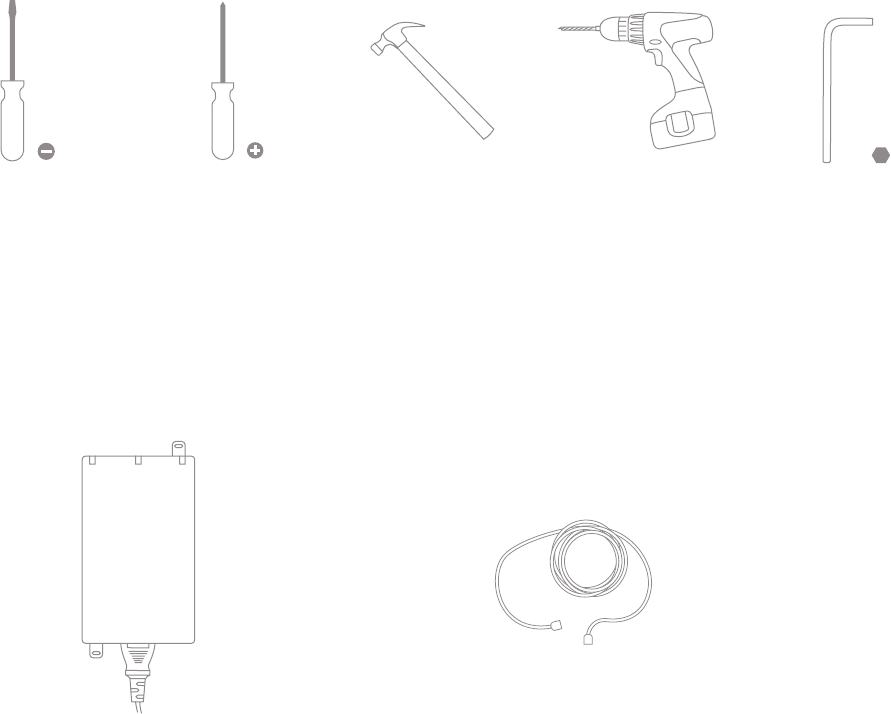
3.3 Collect Tools
You will need the following tools to perform an installation:
Hex wrench
5/64” (2.0)
Hammer Drill with 5/32”
(4mm) bits
3.4 Collect Additional Hardware for Installation
802.3af PoE power source (either PoE
switch or Meraki 802.3af PoE Injector)
Network cables with RJ45 connectors long
enough for your particular mounting location
9
4 Installation Instructions
4.1 Choose Your Mounting Location
A good mounting location is important to getting the best performance out of your MR14 access point.
Keep the following in mind:
1. The device should have unobstructed line of sight to most coverage areas. For example, if installing
in an office filled with workspaces divided by mid-height cubicle walls, installing on the ceiling or high
on a wall would be ideal.
2. Power over Ethernet supports a maximum cable length of 300 ft (100 m).
3. If being used in a mesh deployment, the MR14 should have line of sight to at least two other Meraki
devices. For more detailed instructions regarding access point location selection, reference the Meraki
Network Design Guide (meraki.com/collateral).
4.2 Install the MR14
For most mounting scenarios, the MR14 mount plate provides a quick, simple and flexible means of
mounting your device. The installation should be done in two steps. First, install the mount plate to
your selected location. Then, attach the MR14 to the mount plate.
4.2.1 Attach the Mount Plate
The MR14 mount plate can be used to install your access point in a wide range of scenarios: wall
or solid ceiling, below a suspended ceiling, various electrical junction boxes or above a suspended
ceiling (in the plenum). The mount plate contains a variety of hole patterns that are customized for
each installation scenario.
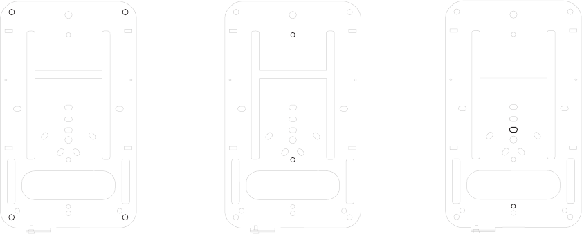
The following images show the hole patterns that should be used for each type of mount:
Wall Mount (also marked with
W on the mount plate)
4” Square Cable Junction Box
Mount (US style) European Outlet Box
10
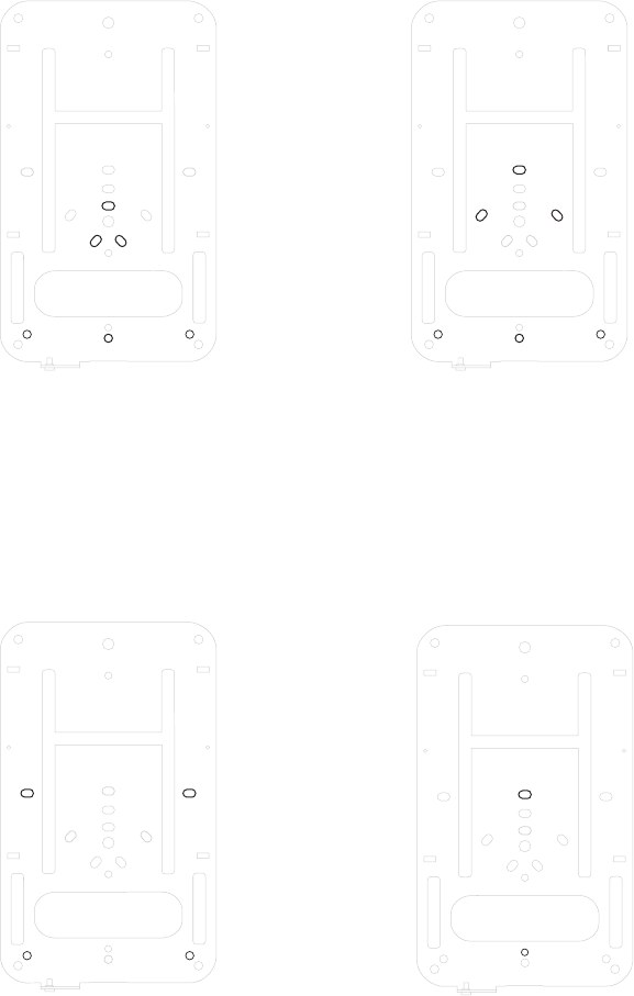
3.5” Round Cable Junction Box
Mount (US style)
Single-Gang Outlet Box (US style) Single-gang junction box (US style)
4” Round Cable Junction Box Mount
(US style)
11
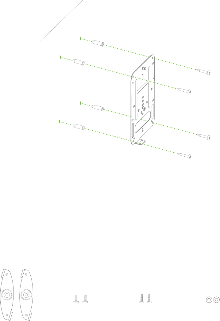
4.2.1.1 Wall or Solid Ceiling Mount Using Mount Plate
Using included wall anchors and screws, attach the mount plate to your mounting wall or ceiling.
It is recommended that the MR14 be mounted to a wall or solid ceiling using the mount plate
for physical security reasons.
4.2.1.2 Drop Ceiling Mount Using Mount Plate
To mount your MR14 on a drop ceiling T-rail, use the included T-rail mounting accessory kit.
The accessory kit can be used to mount to most 9/16”, 15/16” or 1 ½” T-rails.
The kit contains:
T-rail Mounting Kit
With set screws
6-32-4” screws
(includes 2 spares)
6-32-7” screws
(includes 2 spares)
2 rubber spacers
x 4 x 4
12
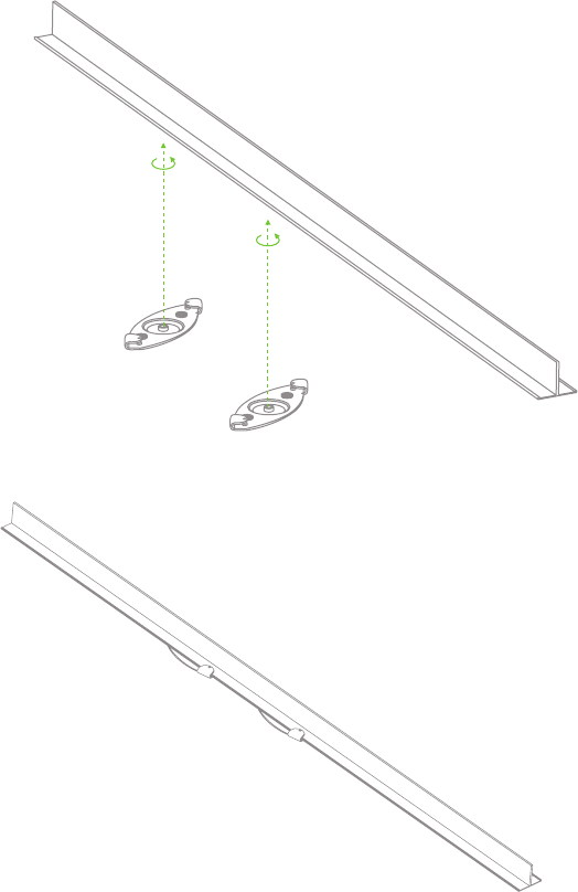
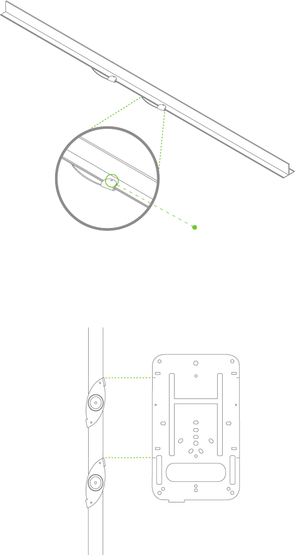
1. Attach the T-rail clips to the T-rail by rotating them and snapping them into place as shown.
The black foam pads should be compressed slightly after installation.
13
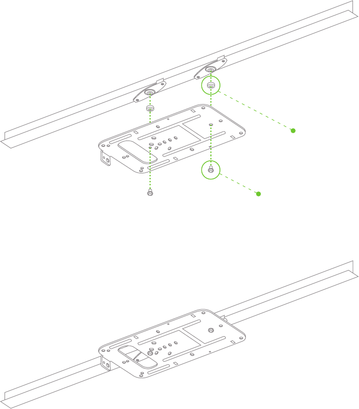
3. Tighten the set screws on the T-rail clips to secure the clips using a 5/64”(2 mm) hex key.
Set screws (x4)
2. Using the hash marks on the edge of the mount plate as a guide, set the proper spacing
of the T-rail clips on the T-rail
14
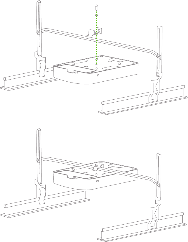
4. Attach the mount plate to the T-rail clips. Attach the mount plate to the installed T-rail clips
using the 6-32-4” screws through the T-rail mount holes on the mount plate (marked with
a T on the mount plate) as shown. For recessed T-rails, use the included 6-32-7” screws
and rubber spacers. For recessed T-rail case, pre-assemble the spacers and screws to the
mount plate by pushing the screws through the mount plate holes into the rubber spacers.
At this point the plate can be held with one hand while the other hand holds a screwdriver.
Rubber spacers
(Recessed T-rail only)
Flush T-rail: 6-32-4” screws
Recessed T-rail: 6-32-7” screws
15
4.2.1.3 Electrical Junction Box Mount Using Mount Plate
The MR14 can be mounted to a 4” square cable junction box, a 3.5 or 4” round cable
junction box or various U.S. and European outlet boxes (mounting screws are not included).
Using appropriate mounting hardware for your specific type of junction box, attach the mount
plate to the junction box.
4.2.2 Power the MR14
1. If mounting to an electrical junction box, feed the Ethernet cable through the cable access
hole in the Mount Plate:
Cable access hole
If mounting to a wall or ceiling, the Ethernet cable will feed through the cable slot on bottom
of the MR14 once the device is installed on the mount plate.
16
2. Plug the Ethernet cable into the PoE+GigE port in the MR14 cable bay.
3. Plug the other end of the Ethernet cable into an 802.3af-compliant power source, either a PoE
switch or the Meraki 802.3af PoE Injector. The PoE injector should be used if the MR14 is being
deployed as a repeater.
4.2.3 Mount the MR14
(Attached Ethernet cable is not shown for simplicity of illustration)
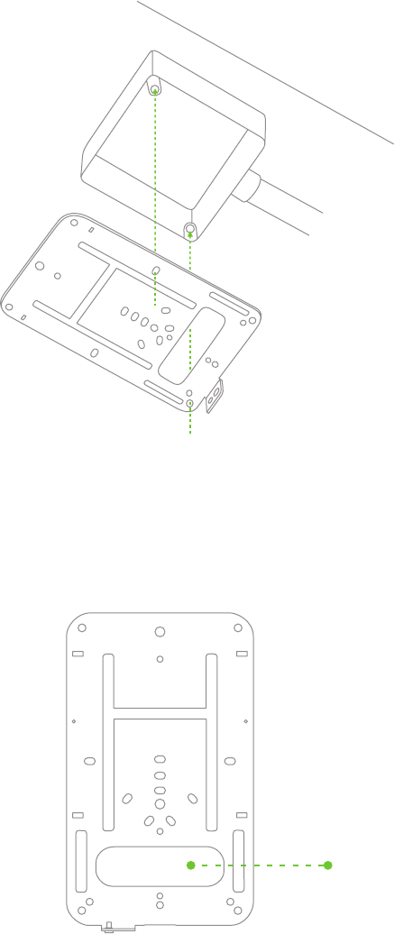
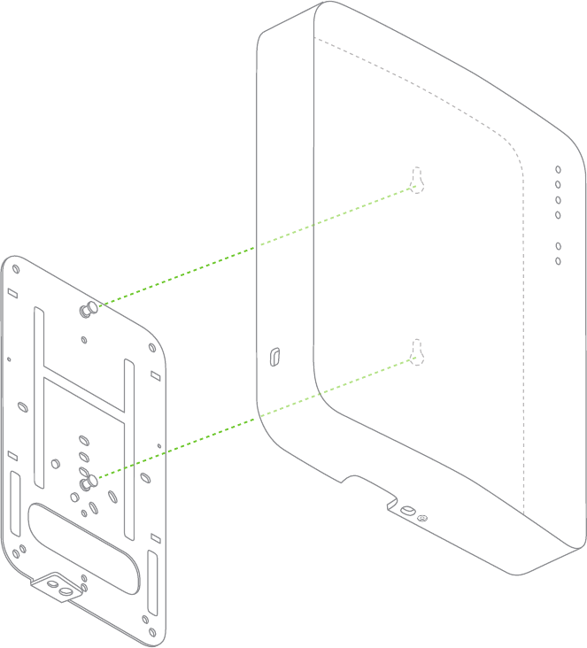
4.2.3.1 Assemble MR14 to the Mount Plate
(This section applies to Wall and/or Solid Ceiling, Drop Ceiling or Electrical Junction box mount where
you have already installed the mount plate.)
Insert the posts on the mount plate into the mount plate attachment slots on the back of the device.
17
To line the posts up with the slots properly, line up the corners of the cable pass-through
slot on the bottom of the unit with the two hash marks on the mount plate. Then slide the
unit down until it clicks into place.
2
1
18
4.2.3.2 Desk or Shelf Mount
The MR14 can be placed on a desk or shelf resting on the non-scratch rubber feet.
The mount plate is not necessary for a desk or shelf mounting.
4.2.3.3 Wall or Solid Ceiling Mount without Mount Plate
The MR14 can also be mounted on a wall without using the mount plate if desired to
utilize an existing wall screw or for speed of installation (only two screws need to be
installed instead of four for the mount plate.
Using the two holes marked with a T on the mount plate as a template for hole spacing,
mark the locations to install screws in the wall using a pencil.
Install appropriate screws in the wall at the marked locations. Maximum screw head diameter
should be 0.22” (5.5 mm). Leave approximately 0.3” (7.5 mm) of screw sticking out of the wall.
19
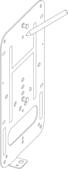
4.2.3.4 Plenum Mount (Above Dropped Ceiling)
The MR14 can be mounted to the T-bar grid above the tiles of a suspended ceiling using a 3rd party
T-bar box hanger (not included). The Erico Caddy 512A is recommended and is used in installation
instruction illustrations.
Note: a UL2043-rated Ethernet cable should be used for a plenum installation.
1. Adjust the height of the T-bar box hanger crossbar to make sure there is adequate clearance between
the access point and the top of the ceiling tiles. Tighten the height adjusting screws.
2. Securely attach the T-rail clips on either side of the T-bar box hanger to the suspended ceiling grid T-rails.
3. Connect a grounding wire (not included with T-bar box hanger) to the grounding hole in the bracket
mounting clip and to metal building structure. A grounding wire is required to comply with the U.S.
National Electric Safety Code.
4. Attach the bracket mounting clip (included with T-bar box hanger) to the center of the T-bar box hanger crossbar.
5. Attach the MR14 to the access point mounting bracket using a 6-32 screw and washer (not included with
T-bar box hanger) and the multi-purpose mounting hole on the back of the access point (referenced on p. 7.)
20
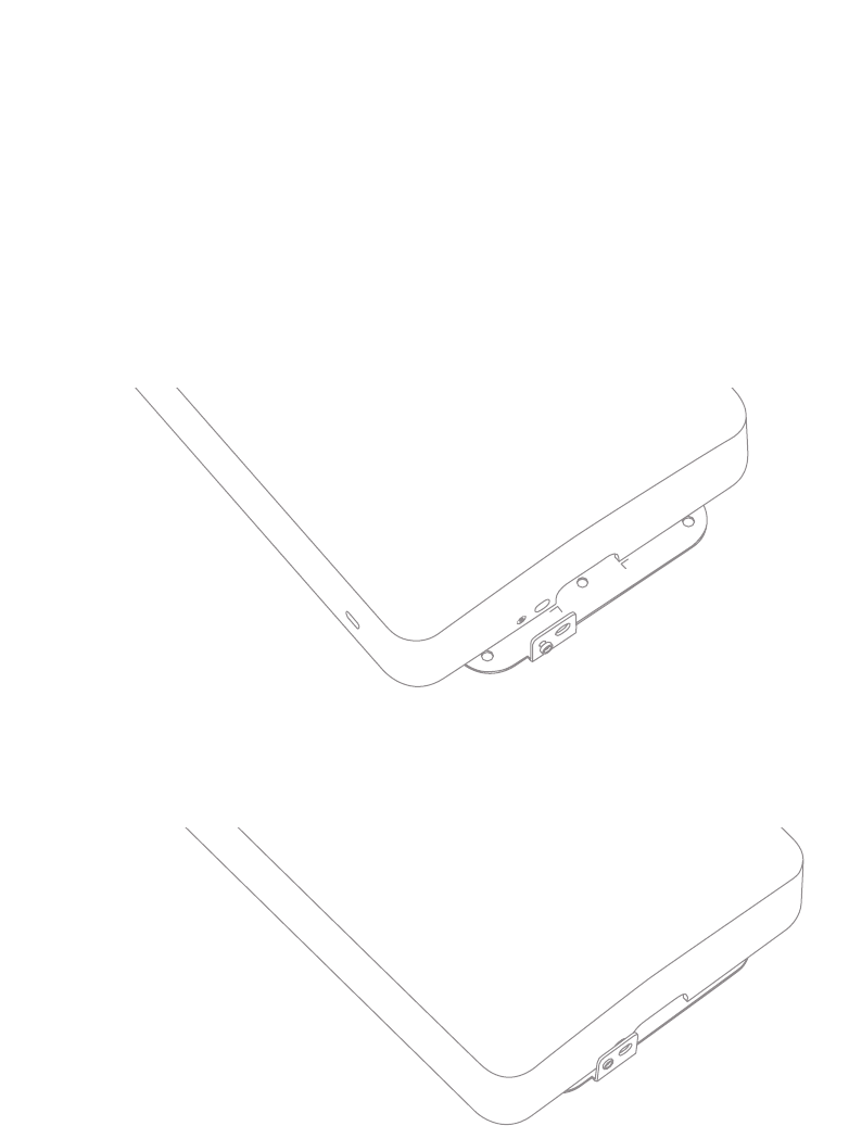
4.3 Secure the MR14
Depending on your mounting environment, you may want to secure the MR14 to its mount location.
Your MR14 can be secured in several ways. If the MR14 has been installed using the mount plate,
it can be secured via security screw (included; captive in mount plate), Masterlock 120T or equivalent
pad lock and/or Kensington lock. If the mount plate was not used, the MR14 can still be secured
using a Kensington lock.
Pad lock installed
Kensington lock hard point
Security screw engaged
Security Screw
Screw the captive security screw on the lower mount plate tab into place.
Pad Lock
Attach pad lock (Masterlock 120T or equivalent) to pad lock hard point on bottom of device.
Kensington Lock
Attach a Kensington lock cable to the access point at the hard point on the side of the device.
Attach the other end of the cable to a secure location, such as a pipe or building fixture.
Device secured with security screw and pad lock
21
4.4 Verify Device Functionality and Test Network Coverage
1. Check LEDs
The Radio Power LED should be solid green. If it is flashing orange, the firmware is automatically
upgrading and the LED should turn green when the upgrade is completed (normally completed in
under thirty minutes). If the device is a gateway, the Ethernet LED and the four Signal Strength
LEDs should be green as well. If the device is a repeater only, the Ethernet LED will not be
illuminated and the number of green Signal Strength LEDs will depend on strength of connection
to the nearest Meraki device. See LED Indicator section of Hardware Installation Guide on p. XX
for further details about information conveyed by LEDs.
Note: Your MR14 must have an active route to the Internet to check and upgrade its firmware.
2. Verify access point connectivity
Use any 802.11 client device to connect to the MR14 and verify proper connectivity using the
client’s web browser.
3. Check network coverage
Confirm that you have good signal strength throughout your coverage area. You can use the
signal strength meter on a laptop, smart phone or other wireless device.
5 Troubleshooting
Reference the Meraki knowledge base at http://meraki.com/help/kb for additional information and
troubleshooting tips.
22
6 Regulatory Information
U.S. Regulatory Wireless Notice
Federal Communication Commission Interference Statement:
This equipment has been tested and found to comply with the limits for a Class B digital device, pursuant
to Part 15 of the FCC Rules. These limits are designed to provide reasonable protection against harmful
interference in a residential installation. This equipment generates, uses and can radiate radio frequency
energy and, if not installed and used in accordance with the instructions, may cause harmful interference
to radio communications. However, there is no guarantee that interference will not occur in a particular
installation. If this equipment does cause harmful interference to radio or television reception, which can
be determined by turning the equipment off and on, the user is encouraged to try to correct the interference
by one of the following measures:
• Reorient or relocate the receiving antenna.
• Increase the separation between the equipment and receiver.
• Connect the equipment into an outlet on a circuit different from
that to which the receiver is connected.
• Consult the dealer or an experienced radio/TV technician for help.
FCC Caution:
Any changes or modifications not expressly approved by the party responsible for compliance could void
the user’s authority to operate this equipment.
This device complies with Part 15 of the FCC Rules. Operation is subject to the following two conditions:
• this device may not cause harmful interference, and
• this device must accept any interference received, including interference
that may cause undesired operation.
FCC Radiation Exposure Statement:
This equipment complies with FCC radiation exposure limits set forth for an uncon-trolled environment.
This equipment should be installed and operated with minimum distance 20 cm between the radiator
and your body. This transmitter must not be co-located or operating in conjunction with any other
antenna or transmitter.
IEEE 802.11b or 802.11g operation of this product in the USA is firmware-limited to channels 1 through 11.
If this device is going to be operated in 5.15 ~ 5.25GHz frequency range, then it is restricted in indoor
environment only.
23
Canadian Regulatory Wireless Notice
This device complies with RSS-210 of the Industry Canada Rules. Operation is subject to
the following two conditions:
• this device may not cause interference and
• this device must accept any interference, including interference
that may cause undesired operation of the device.
IC Radiation Exposure Statement:
This equipment complies with IC radiation exposure limits set forth for an uncontrolled environment.
This equipment should be installed and operated with minimum distance 20 cm between the radiator
and your body.
This device is intended only for OEM integrators under the following conditions:
• the antenna must be installed such that 20 cm is maintained between the antenna and users, and
• the transmitter module may not be co-located with any other transmitter or antenna,
• for all products market in US/IC, OEM has to limit the operation channels in CH1 to CH11 for 2.4G
band by supplied firmware programming tool. OEM shall not supply any tool or info to the end-user
regarding to Regulatory Domain change.
As long as 3 conditions above are met, further transmitter test will not be required. However, the OEM
integrator is still responsible for testing their end-product for any additional compliance requirements
required with this module installed (for example, digital device emissions, PC peripheral requirements, etc.).
Important Note:
In the event that these conditions can not be met (for example certain laptop configurations or co-location
with another transmitter), then the FCC/IC authorization is no longer considered valid and the FCC/IC ID
can not be used on the final product. In these circumstances, the OEM integrator will be responsible for
re-evaluating the end product (including the transmitter) and obtaining a separate FCC/IC authorization.
End Product Labeling:
This transmitter module is authorized only for use in device where the antenna may be installed such that
20 cm may be maintained between the antenna and users. The final end product must be labeled in a
visible area with the following: “Contains FCC ID: UDX-MERAKI-MINI, IC ID: 6961A-MRKIMINI”.
Manual Information To the End User:
The OEM integrator has to be aware not to provide information to the end user regarding how to install
or remove this RF module in the user’s manual of the end product which integrates this module.
The end user manual shall include all required regulatory information/warning as show in this manual.

24
Europe – EU Declaration of Conformity
This device complies with the essential requirements of the R&TTE Directive 1999/5/EC.
The following test methods have been applied in order to prove presumption of conformity with the
essential requirements of the R&TTE Directive 1999/5/EC:
EN 60 950-1: 2001 +A11: 2004
Safety of Information Technology Equipment
EN 50385: 2002
Product standard to demonstrate the compliance of radio base stations and fixed terminal stations
for wireless telecommunication systems with the basic restrictions or the reference levels related to
human exposure to radio frequency electromagnetic fields (110MHz - 40 GHz) - General public
EN 300 328 V1.7.1 (2006-10)
Electromagnetic compatibility and Radio spectrum Matters (ERM); Wideband transmission systems;
Data transmission equipment operating in the 2,4 GHz ISM band and using wide band modulation
techniques; Harmonized EN covering essential requirements under article 3.2 of the R&TTE Directive
EN 301 489-1 V1.6.1 (2005-09)
Electromagnetic compatibility and Radio Spectrum Matters (ERM); Electro-Magnetic Compatibility (EMC)
standard for radio equipment and services;
Part 1: Common technical requirements
EN 301 489-17 V1.2.1 (2002-08)
Electromagnetic compatibility and Radio spectrum Matters (ERM); Electro-Magnetic Compatibility (EMC)
standard for radio equipment and services;
Part 17: Specific conditions for 2,4 GHz wideband transmission systems
and 5 GHz high performance RLAN equipment
This device is a 2.4 GHz and 5 GHz wideband transmission system (transceiver), intended for use in all EU
member states and EFTA countries with the following restrictions:
In Italy the end-user should apply for a license at the national spectrum authorities in order to obtain
authorization to use the device for setting up outdoor radio links and/or for supplying public access to
telecommunications and/or network services.
This device may not be used for setting up outdoor radio links in France and in some areas the RF output
power may be limited to 10 mW EIRP in the frequency range of 2454 – 2483.5 MHz. For detailed information
the end-user should contact the national spectrum authority in France.
In Austria, Belgium, Bulgaria, Estonia, Finland, Malta and Slovakia the device may not be used in the 5 GHz
spectrum unless the 5.745-5.825 GHz and has been disabled. This can be done through the Meraki Dashboard.
25
Česky(Czech)
Meraki,Inc.tímtoprohlašuje,žetentowirelessdevicejeveshoděsezákladnímipožadavky
adalšímipříslušnýmiustanovenímisměrnice.
Dansk(Danish)
UndertegnedeMeraki,Inc.erklærerherved,atfølgendeudstyrwirelessdeviceoverholder
devæsentligekravogøvrigerelevantekravidirektiv1999/5/EF.
Deutsch(German)
HiermiterklärtMeraki,Inc.,dasssichdasGerätwirelessdeviceinÜbereinstimmungmit
dengrundlegendenAnforderungenunddenübrigeneinschlägigenBestimmungender
Richtlinie1999/5/EGbendet.
Eesti(Estonian)
KäesolevagakinnitabMeraki,Inc.seadmewirelessdevicevastavustdirektiivi1999/5/EÜ
põhinõuetelejanimetatuddirektiivisttulenevatele.
English
Hereby,Meraki,Inc.,declaresthatthiswirelessdeviceisincompliancewiththeessential
requirementsandotherrelevantprovisionsofDirective1999/5/EC.
Español(Spanish)
PormediodelapresenteMeraki,Inc.declaraqueelwirelessdevicecumpleconlosrequisitos
esencialesycualesquieraotrasdisposicionesaplicablesoexigiblesdelaDirectiva1999/5/CE.
Ελληνική(Greek)
ΜΕΤΗΝΠΑΡΟΥΣΑMeraki,Inc.ΔΗΛΩΝΕΙΟΤΙwirelessdeviceΣΥΜΜΟΡΦΩΝΕΤΑΙΠΡΟΣΤΙΣ
ΟΥΣΙΩΔΕΙΣΑΠΑΙΤΗΣΕΙΣΚΑΙΤΙΣΛΟΙΠΕΣΣΧΕΤΙΚΕΣΔΙΑΤΑΞΕΙΣΤΗΣΟΔΗΓΙΑΣ1999/5/ЕΚ.
Français(French)
ParlaprésenteMeraki,Inc.déclarequel’appareilwirelessdeviceestconformeauxexigences
essentiellesetauxautresdispositionspertinentesdeladirective1999/5/CE.
Italiano(Italian)
ConlapresenteMeraki,Inc.dichiarachequestowirelessdeviceèconformeairequisitiessenziali
edallealtredisposizionipertinentistabilitedalladirettiva1999/5/CE.
Latviski(Latvian)
AršoMeraki,Inc.deklarē,kawirelessdeviceatbilstDirektīvas1999/5/EKbūtiskajāmprasībām
uncitiemartosaistītajiemnoteikumiem.
26
Lietuvių(Lithuanian)
ŠiuoMeraki,Inc.deklaruoja,kadšiswirelessdeviceatitinkaesminiusreikalavimusir
kitas1999/5/EBDirektyvosnuostatas.
Nederland(Dutch)
HierbijverklaartMeraki,Inc.dathettoestelwirelessdeviceinovereenstemmingis
metdeessentiëleeisenendeandererelevantebepalingenvanrichtlijn1999/5/EG.
Malti(Maltese)
Hawnhekk,Meraki,Inc.,jiddikjaralidanwirelessdevicejikkonformamal-ħtigijiet
essenzjaliumaprovvedimentioħrajnrelevantilihemmd-Dirrettiva1999/5/EC.
Magyar(Hungarian)
Alulírott,Meraki,Inc.nyilatkozom,hogyawirelessdeviccemegfelelavonatkozó
alapvetõkövetelményeknekésaz1999/5/ECirányelvegyébelõírásainak.
Polski(Polish)
NiniejszymMeraki,Inc.oświadcza,żewirelessdevicejestzgodnyzzasadniczymi
wymogamiorazpozostalymistosownymi
Português(Portuguese)
Meraki,Inc.declaraqueestewirelessdeviceestáconformecomosrequisitosessenciais
eoutrasdisposiçõesdaDirectiva1999/5/CE.
Slovensko(Slovenian)
Meraki,Inc.izjavlja,dajetawirelessdevicevskladuzbistvenimizahtevamiinostalimi
relevantnimidolocilidirektive1999/5/ES.
Slovensky(Slovak)
Meraki,Inc.týmtovyhlasuje,žewirelessdevicesplnazákladnépožiadavkyavšetkypríslušné
ustanoveniaSmernice1999/5/ES.
Suomi(Finnish)
Meraki,Inc.vakuuttaatätenettäwirelessdevicetyyppinenlaiteondirektiivin1999/5/EY
oleellistenvaatimustenjasitäkoskeviendirektiivinmuidenehtojenmukainen.
Svenska(Swedish)
HärmedintygarMeraki,Inc.attdennawirelessdevicestårIöverensstämmelsemedde
väsentligaegenskapskravochövrigarelevantabestämmelsersomframgårdirektiv1995/5/EG.

27
Copyright
© 2009 Meraki, Inc. All rights reserved.
Trademarks
Meraki® is a registered trademark of Meraki, Inc.
Warranty
Meraki hardware products are protected by the standard Meraki warranty of one year parts/labor.
For more information, refer to the Meraki End User License Agreement.

28
www.meraki.com
99 Rhode Island St., Second Floor
San Francisco, California 94103
Phone: +1 415 632 5900
Fax: +1 415 632 5890
© Meraki, Inc. 2009 280-09100-A