Cisco Systems 60019010 802.11 a/b/g/n Wireless Access Point User Manual meraki setup guide MR62 66

Cisco Systems 802.11 a/b/g/n Wireless Access Point meraki setup guide MR62 66

Contents

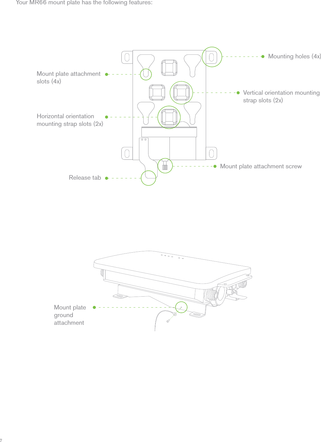
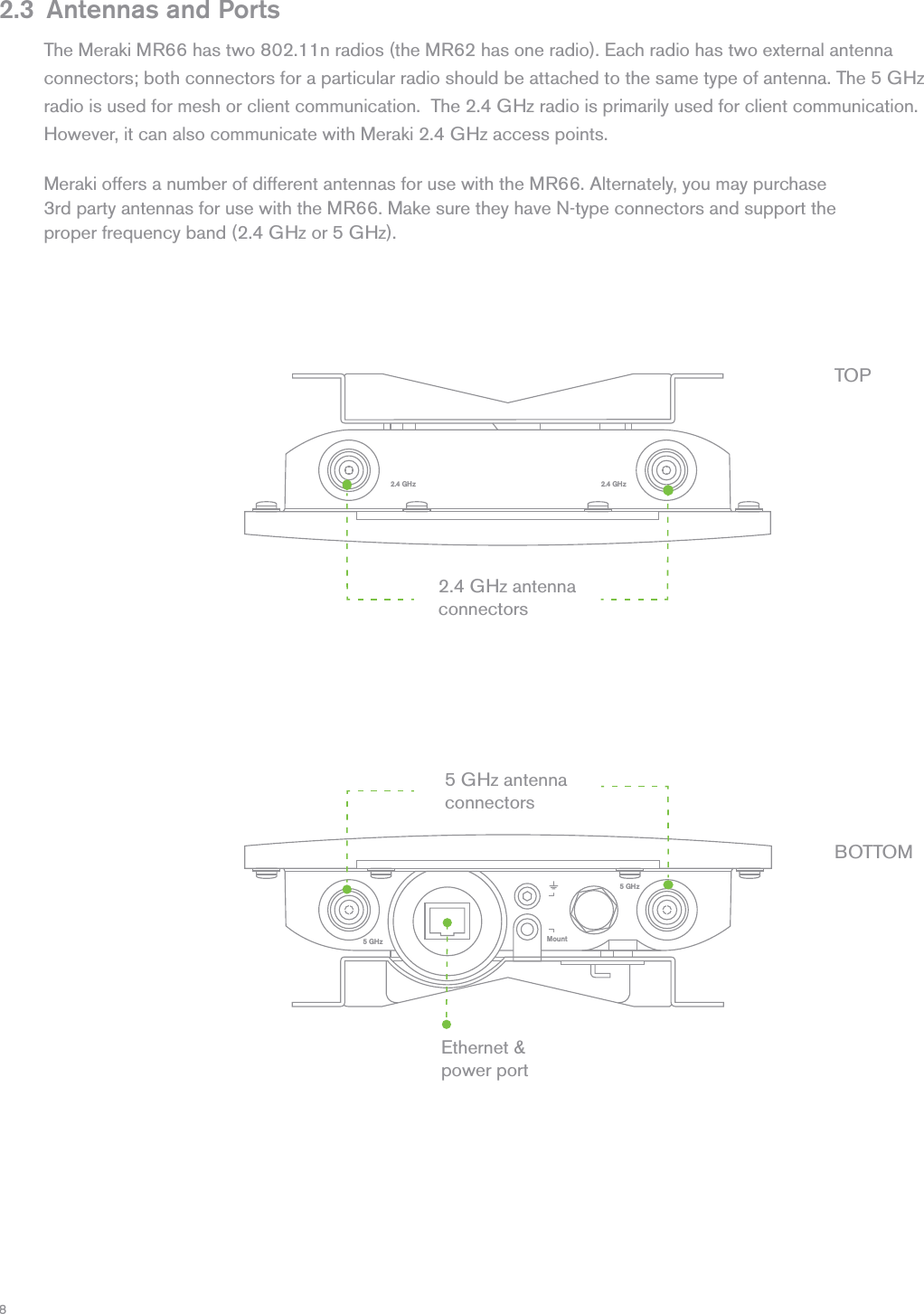
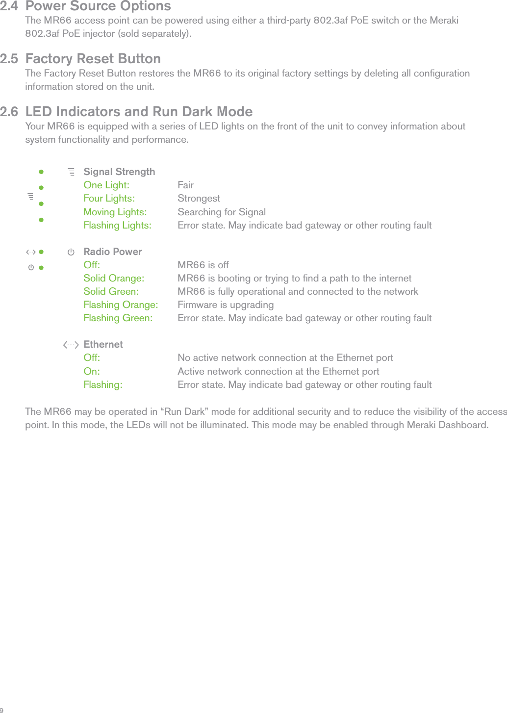
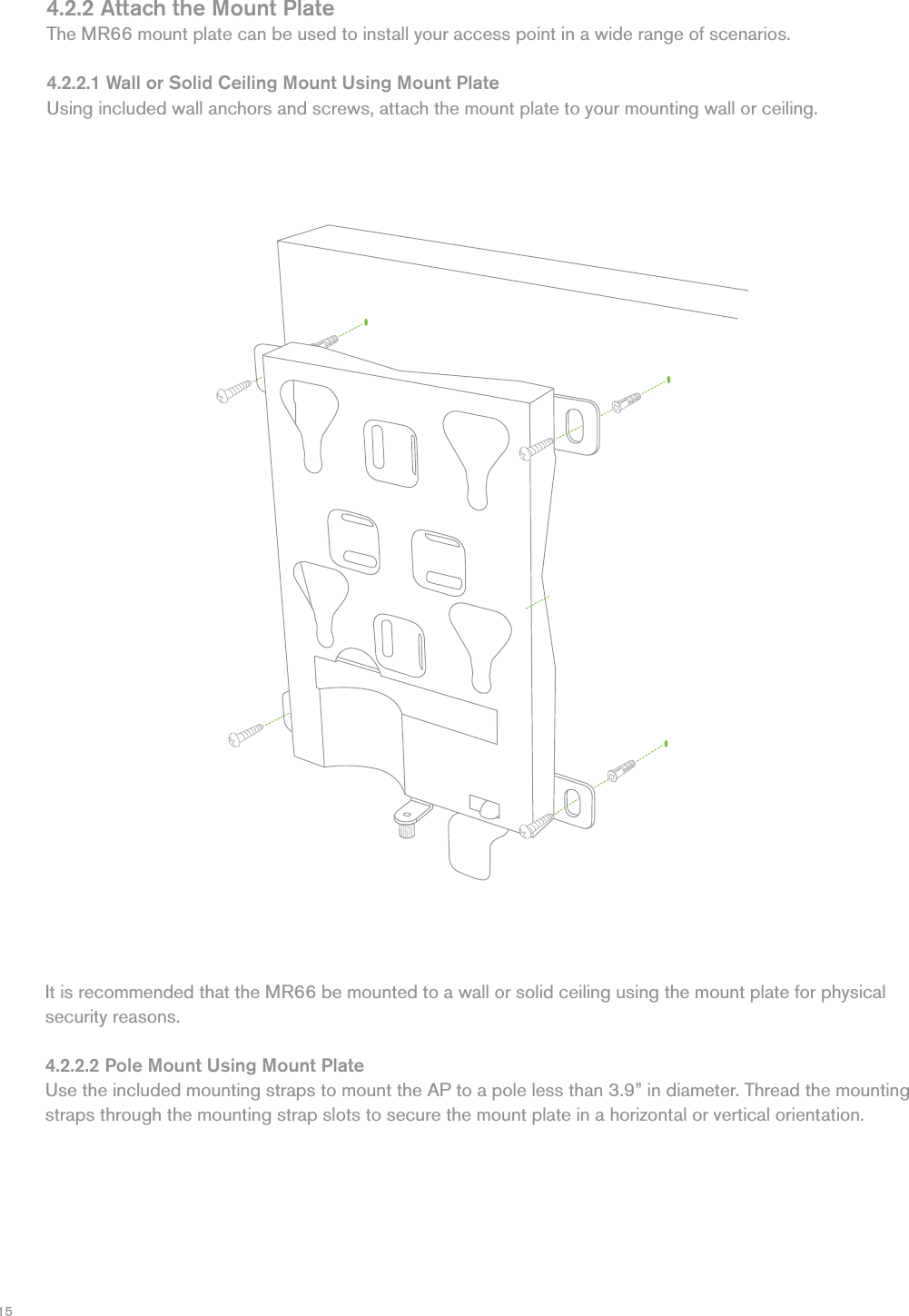
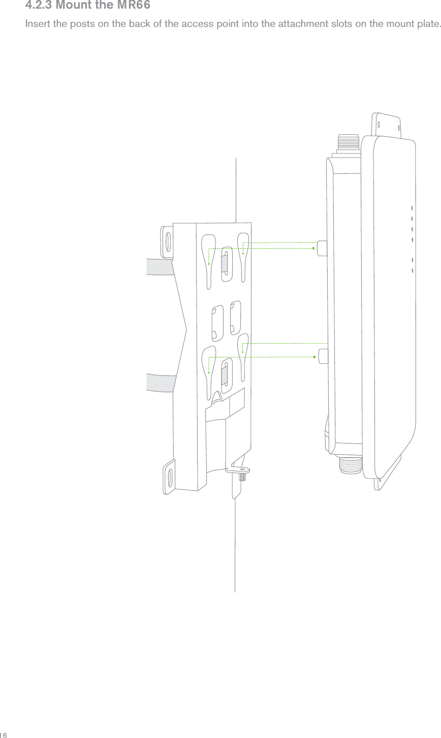
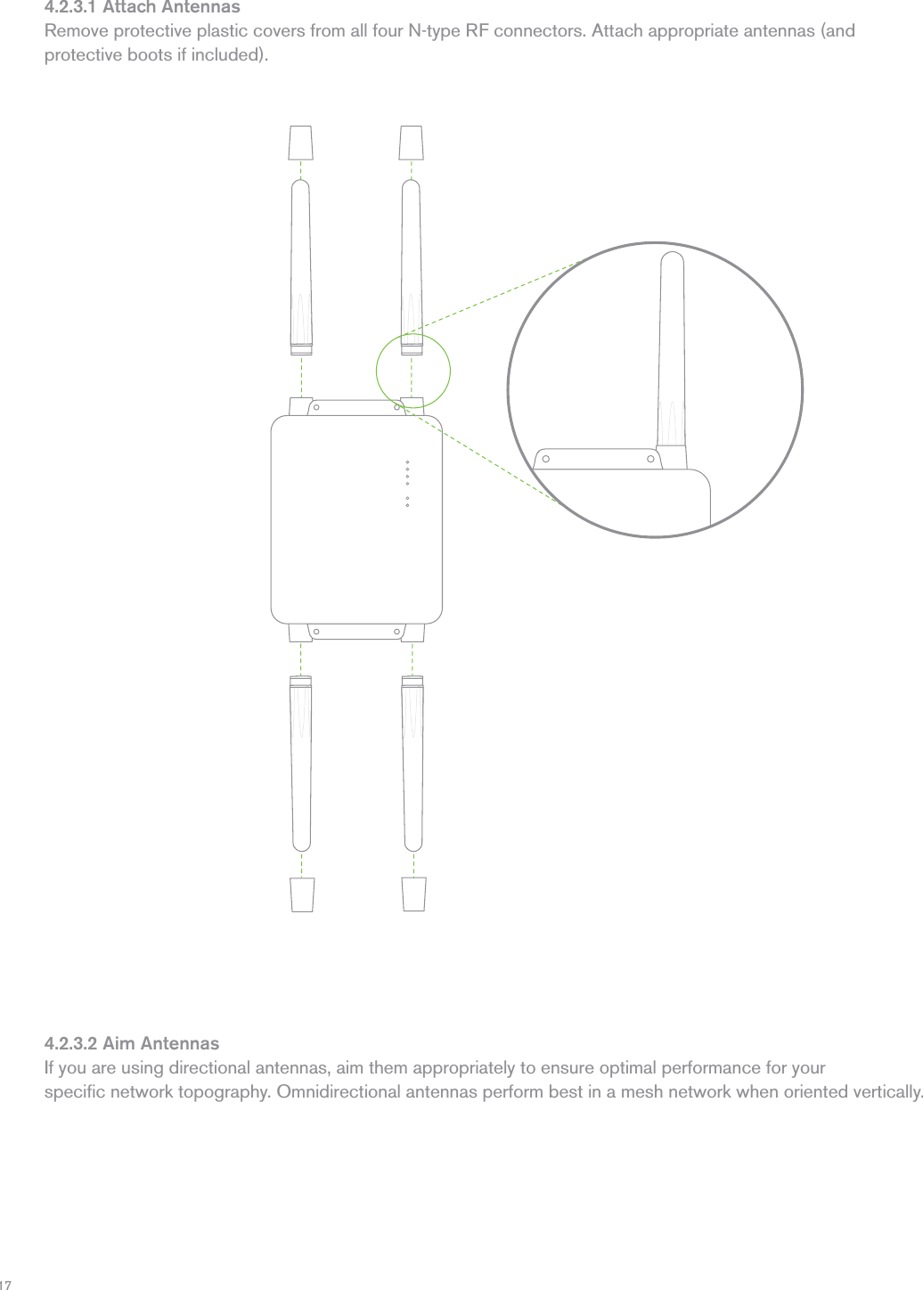
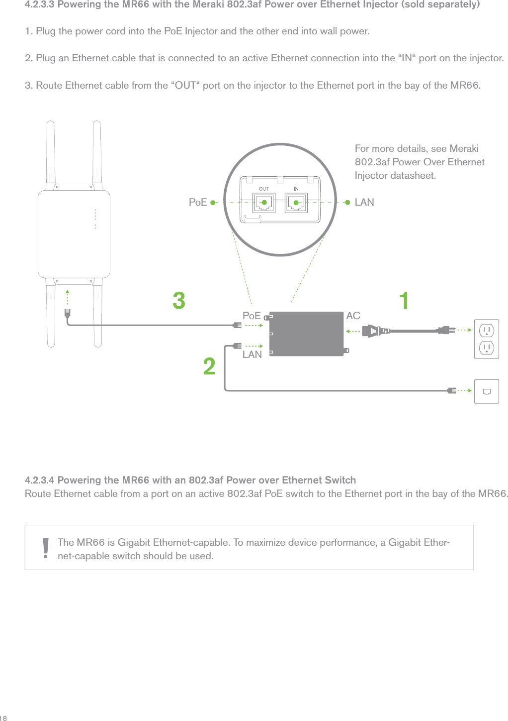
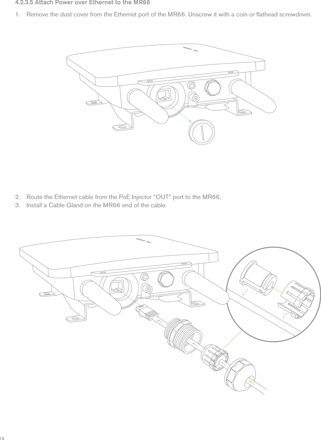
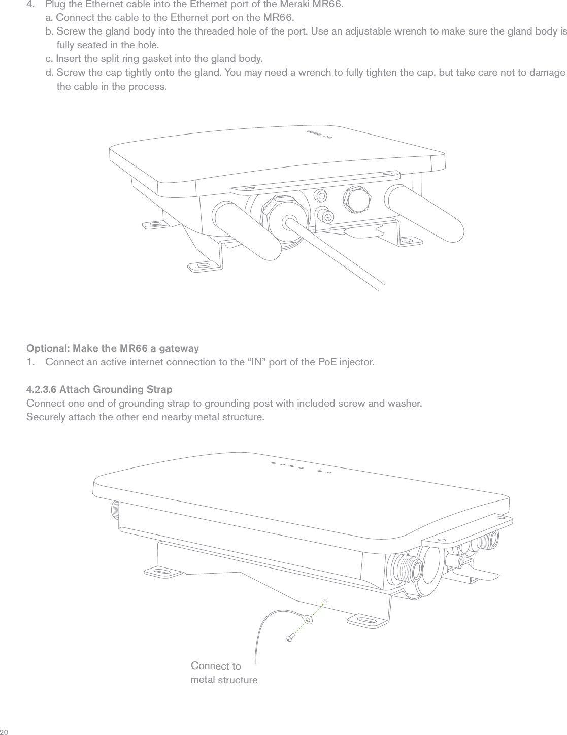
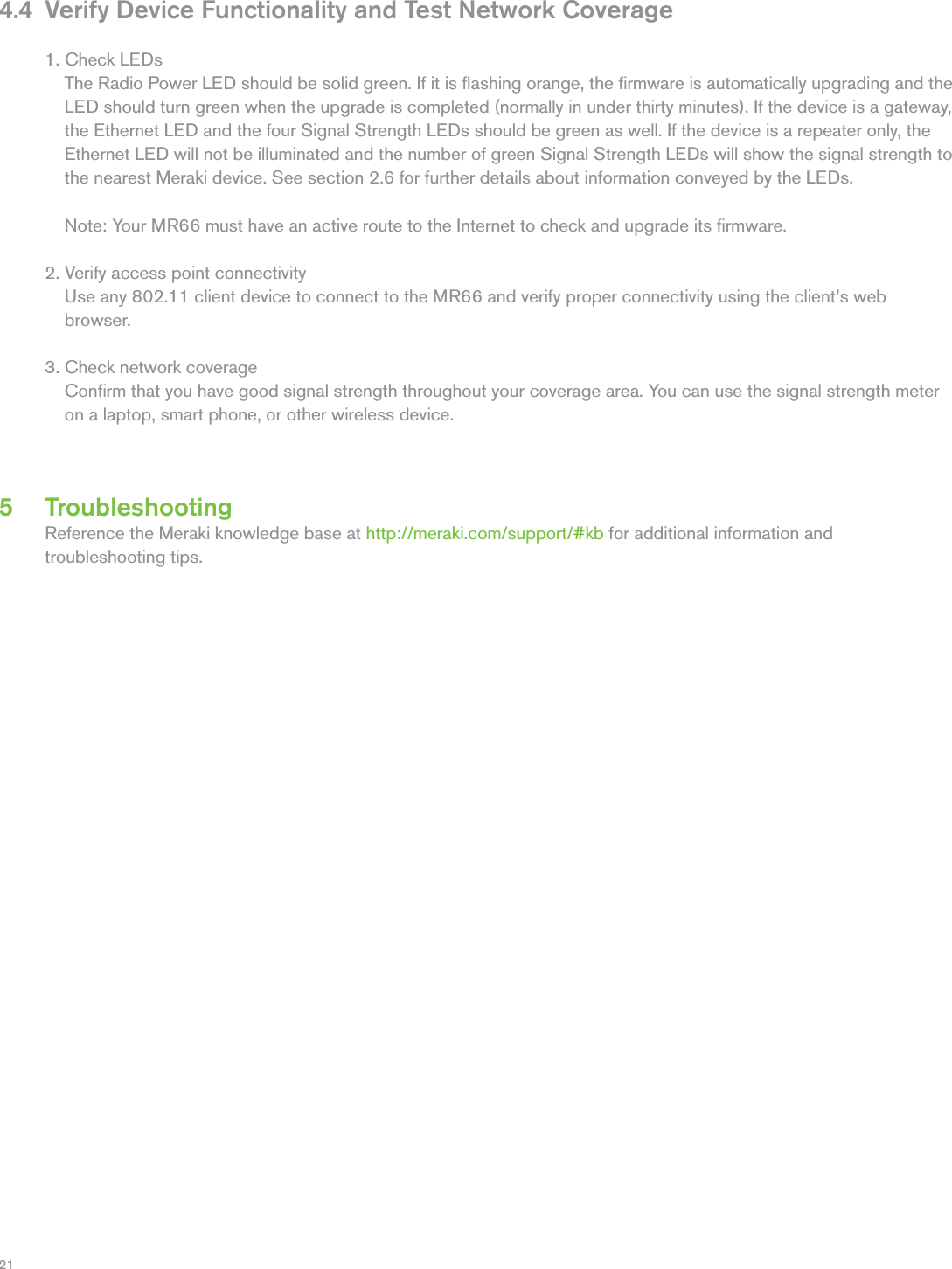
User Manual - Operation

TrademarksMeraki, Meraki MR62, MR66, amd Meraki Cloud Controller are trademarks of Meraki, Inc. Other brand and product names are registered trademarks or trademarks of their respective holders.WarrantyMeraki, Inc. provides a one year warranty on this product. Warranty details may be found at www.meraki.com/support.
3Table of Contents1 Scope of Document and Related Publications 42 MR66 Overview 52.1 Package Contents 52.2 Understanding the MR66 62.3 Antennas and Ports 82.4 Power Source Options 92.5 Factory Reset Button 92.6 LED Indicators and Run Dark Mode 93  Pre-Install Preparation 103.1 Configure Your Network in Dashboard 103.2 Check and Upgrade Firmware 10 3.3 Check and Configure Firewall Settings 103.4 Assigning IP Addresses to MR66s 11    3.4.1 Dynamic Assignment 11    3.4.2 Static Assignment 113.5 Collect Tools 12 3.6 Collect Additional Hardware for Installation 124  Installation Instructions 134.1 Choose Your Mounting Location 13 4.2 Install the MR66 13    4.2.1 Attach the Mount Plate 14      4.2.2.1 Wall or Solid Ceiling Mount Using Mount Plate 15      4.2.2.2 Pole Mount Using Mount Plate 15    4.2.3 Mount the MR66 16      4.2.3.1 Attach Antennas 17      4.2.3.2 Aim Antennas 17       4.2.3.3 Powering the MR66 with Meraki 802.3af Power over Ethernet Injector 18       4.2.3.4 Powering the MR66 with an 802.3af Power over Ethernet Switch 18       4.2.3.5 Attach Power over Ethernet to the MR66 19       4.2.3.6 Attach Grounding Strap 20  4.4 Verify Device Functionality and Test Network Coverage 21 5 Troubleshooting 21 6  Regulatory Information 22
41 Scope of Document and Related PublicationsThe MR62/66 Hardware Installation Guide describes the installation procedure for the MR62 and MR66 access points.   Note: All instructions in this hardware installation guide reference the MR66 but apply equally to the MR62, except where noted.Additional reference documents are available online at meraki.com/support/#documentation.
5MR66 access point Mounting plate Mounting strapsWall screws & anchors2 MR66 OverviewThe Meraki MR66 is an enterprise-class, 802.11n access point designed for rugged environments.  When connected to the Meraki Cloud Controller, the MR66 enables the creation of high-speed and reliable networks that cover large outdoor and industrial areas quickly, easily, and cost-effectively.2.1 Package ContentsThe MR66 package contains the following: Cable gland
62.2 Understanding the MR66Your Meraki MR66 has the following features: LED indicatorsVent  The vent allows pressure and humidity equalization between the interior and the enviroment. This prevents internal condensation and maintains a water proof seal.Grounding Post  Provides an attachment point on the access point for the grounding strap (included). This post is threaded to accept a M4 x 0.7mm boltMount5 GHz5 GHzGrounding postVentFactory reset buttonAccessory antennaattachment holes Mount attachmentposts (4x)
7Release tabVertical orientation mounting strap slots (2x)Horizontal orientation mounting strap slots (2x)Mount plate attachment screwMount plate groundattachmentYour MR66 mount plate has the following features: Mount plate attachment slots (4x)Mounting holes (4x)
82.3 Antennas and PortsBOTTOMThe Meraki MR66 has two 802.11n radios (the MR62 has one radio). Each radio has two external antenna connectors; both connectors for a particular radio should be attached to the same type of antenna. The 5 GHz radio is used for mesh or client communication.  The 2.4 GHz radio is primarily used for client communication. However, it can also communicate with Meraki 2.4 GHz access points.Meraki offers a number of different antennas for use with the MR66. Alternately, you may purchase 3rd party antennas for use with the MR66. Make sure they have N-type connectors and support the proper frequency band (2.4 GHz or 5 GHz).TOPMount5 GHz5 GHzEthernet & power port5 GHz antenna connectors2.4 GHz 2.4 GHz2.4 GHz antenna connectors
92.4 Power Source OptionsThe MR66 access point can be powered using either a third-party 802.3af PoE switch or the Meraki 802.3af PoE injector (sold separately).2.5 Factory Reset ButtonThe Factory Reset Button restores the MR66 to its original factory settings by deleting all configuration information stored on the unit.2.6 LED Indicators and Run Dark ModeYour MR66 is equipped with a series of LED lights on the front of the unit to convey information about system functionality and performance.Signal Strength One Light: FairFour Lights: StrongestMoving Lights: Searching for Signal  Flashing Lights: Error state. May indicate bad gateway or other routing faultRadio PowerOff: MR66 is off Solid Orange: MR66 is booting or trying to find a path to the internet Solid Green: MR66 is fully operational and connected to the network Flashing Orange: Firmware is upgradingFlashing Green: Error state. May indicate bad gateway or other routing fault EthernetOff: No active network connection at the Ethernet port On: Active network connection at the Ethernet port Flashing: Error state. May indicate bad gateway or other routing fault The MR66 may be operated in “Run Dark” mode for additional security and to reduce the visibility of the access   point. In this mode, the LEDs will not be illuminated. This mode may be enabled through Meraki Dashboard.
103 Pre-Install PreparationYou should complete the following steps before going on-site to perform an installation. 3.1 Configure Your Network in DashboardMeraki recommends that you add your MR66 to a network in Dashboard before mounting it in the field. The following is a brief overview only of the steps required to add an MR66 to your network. For detailed instructions about creating, configuring and managing Meraki wireless networks, refer to the Meraki Cloud Controller Manual (meraki.com/support/#documentation).1. Login to http://dashboard.meraki.com. If this is your first time, create a new account.2. Find the network to which you plan to add your nodes or create a new network. 3. Add your nodes to your network. You will need your Meraki order number (found on your invoice if you     ordered directly from Meraki) or the serial number of each node, which looks like Qxxx-xxxx-xxxx, and is     found on the bottom of the unit.4. Finally, go to the map / floor plan view and place each node on the map by clicking and dragging it to     the location where you plan to mount it. You can always modify the location later.  3.2 Check and Upgrade FirmwareTo ensure your MR66 performs optimally immediately following installation, Meraki recommends that you facilitate a firmware upgrade prior to mounting your MR66.1. Attach your MR66 to power and a wired Internet connection. See p. 19 of this document for details. 2. The MR66 will turn on and the Power LED will glow solid orange. If the unit does not require a firmware     upgrade, the Power LED will turn green within thirty seconds.  * If the unit requires an upgrade, the Power LED will begin blinking orange until the upgrade is complete,     at which point the Power LED will turn solid green. You should allow about an hour for the firmware     upgrade to complete, depending on the speed of your internet connection.3.3 Check and Configure Firewall SettingsIf your network will be located behind a firewall, it must allow outgoing connections on particular ports to particular IP addresses in order for the MR66 to be able to seamlessly communicate with the Cloud Controller.     The most current list of outbound ports and IP addresses can be found here:http://bit.ly/oZpMQ7
113.4 Assigning IP Addresses to MR66sAll gateway MR66s (MR66s with Ethernet connections to the LAN) must be assigned routable IP addresses.  These IP addresses can be dynamically assigned via DHCP or statically assigned.3.4.1 Dynamic AssignmentWhen using DHCP, the DHCP server should be configured to assign a static IP address for each MAC address       belonging to a Meraki AP.  Other features of the wireless network, such as 802.1X authentication, may rely on the property that the APs have static IP addresses.3.4.2 Static AssignmentStatic IPs are assigned using the local web server on each AP.  The following procedure describes how to set the static IP:1. Using a client machine (e.g., a laptop), connect to the AP either wirelessly (by associating to any SSID     broadcast by the AP) or over a wired connection.    If using a wired connection, connect the client machine to the MR66 either through a PoE switch or a Meraki     PoE Injector.  If using a PoE switch, plug an Ethernet cable into the MR66’s Ethernet jack, and the other end     into a PoE switch.  Then connect the client machine over Ethernet cable to the PoE switch.  If using a Meraki     PoE Injector, connect the MR66 to the “PoE” port of the Injector, and the client machine to the “LAN” port.2. Using a web browser on the client machine, access the AP’s built-in web server by browsing to http://my.meraki.com.  Alternatively, browse to http://10.128.128.128.3. Click on the “Static IP Configuration” tab.  Log in.  The default user name is “admin”.  The default password is     the AP’s serial number, with hyphens included (e.g., Q2BD-551C-ZYW3).4. Configure the static IP address, net mask, gateway IP address and DNS servers that this AP will use on its     wired connection.5. If necessary, reconnect the AP to the LAN.
123.6  Collect Additional Hardware for Installation3.5  Collect Tools         You will need the following tools to perform an installation:RecommendedRequiredFlat-headscrewdriverTin snips (if mounting with hose clamps)Phillips screwdriverPower screwdriver with 5/16” (8 mm) nut driver, Phillips & flat heads Drill with appropriate bits for mounting wall anchors (if mounting to a wall) RequiredNetwork cables with RJ45 connectors long enough for your particular mounting location802.3af PoE power source (either PoE switch or Meraki 802.3af PoE Injector)Connection to the internet (if you are setting up your MR66 as a gateway to the internet)Appropriately sized metal straps (if mounting to a pole larger than 3.9” in diameter)Specialized mounting hardware if mounting to surface other than wood, stucco or stoneRecommendedLaptop with wireless to verify setup
134 Installation Instructions4.1 Choose Your Mounting LocationA good mounting location is important to getting the best performance out of your MR66 access point.  Keep the following in mind:1. The device should have unobstructed line of sight to most coverage areas. For example, if installing     in an office filled with workspaces divided by mid-height cubicle walls, installing on the ceiling or high     on a wall would be ideal. 2. Power over Ethernet supports a maximum cable length of 300 ft (100 m). 3. If being used in a mesh deployment, the MR66 should have line of sight to at least two other Meraki     devices. For more detailed instructions regarding access point location selection, reference the Meraki     Network Design Guide (meraki.com/support/#documentation).4. The antennas should be as unobstructed as possible. Make sure that there is clearance around the          MR66 for installation of all of your chosen antennas.4.2 Install the MR66For most mounting scenarios, the MR66 mount plate provides a quick, simple, and flexible means of mounting your device. The installation should be done in two steps. First, install the mount plate to your selected location.    Then attach the MR66 to the mount plate.
144.2.1 Remove the Mount Plate from the Access PointBefore installing the mount plate, you must remove it from the back of the access point.1. Unscrew the mount plate attachment screw.2. Lift the mount plate release tab upwards. .3. While holding the mount plate release tab up, slide the mount plate off the access point in the direction shown below.213
154.2.2 Attach the Mount PlateThe MR66 mount plate can be used to install your access point in a wide range of scenarios.4.2.2.1 Wall or Solid Ceiling Mount Using Mount PlateUsing included wall anchors and screws, attach the mount plate to your mounting wall or ceiling.It is recommended that the MR66 be mounted to a wall or solid ceiling using the mount plate for physical security reasons.4.2.2.2 Pole Mount Using Mount PlateUse the included mounting straps to mount the AP to a pole less than 3.9” in diameter. Thread the mounting straps through the mounting strap slots to secure the mount plate in a horizontal or vertical orientation.
164.2.3 Mount the MR66Insert the posts on the back of the access point into the attachment slots on the mount plate.
174.2.3.1 Attach AntennasRemove protective plastic covers from all four N-type RF connectors. Attach appropriate antennas (and protective boots if included).4.2.3.2 Aim AntennasIf you are using directional antennas, aim them appropriately to ensure optimal performance for your specific network topography. Omnidirectional antennas perform best in a mesh network when oriented vertically.
184.2.3.3 Powering the MR66 with the Meraki 802.3af Power over Ethernet Injector (sold separately)1. Plug the power cord into the PoE Injector and the other end into wall power.2. Plug an Ethernet cable that is connected to an active Ethernet connection into the “IN“ port on the injector.3. Route Ethernet cable from the “OUT“ port on the injector to the Ethernet port in the bay of the MR66.4.2.3.4 Powering the MR66 with an 802.3af Power over Ethernet SwitchRoute Ethernet cable from a port on an active 802.3af PoE switch to the Ethernet port in the bay of the MR66.The MR66 is Gigabit Ethernet-capable. To maximize device performance, a Gigabit Ether-net-capable switch should be used.ACPoELAN132PoE LANFor more details, see Meraki 802.3af Power Over Ethernet Injector datasheet.
194.2.3.5 Attach Power over Ethernet to the MR662. Route the Ethernet cable from the PoE Injector “OUT” port to the MR66. 3. Install a Cable Gland on the MR66 end of the cable.1. Remove the dust cover from the Ethernet port of the MR66. Unscrew it with a coin or flathead screwdriver.
204. Plug the Ethernet cable into the Ethernet port of the Meraki MR66. a. Connect the cable to the Ethernet port on the MR66.  b. Screw the gland body into the threaded hole of the port. Use an adjustable wrench to make sure the gland body is     fully seated in the hole.c. Insert the split ring gasket into the gland body.d. Screw the cap tightly onto the gland. You may need a wrench to fully tighten the cap, but take care not to damage    the cable in the process.Connect to metal structureOptional: Make the MR66 a gateway1. Connect an active internet connection to the “IN” port of the PoE injector.  4.2.3.6 Attach Grounding StrapConnect one end of grounding strap to grounding post with included screw and washer. Securely attach the other end nearby metal structure.
214.4 Verify Device Functionality and Test Network Coverage1. Check LEDs    The Radio Power LED should be solid green. If it is flashing orange, the firmware is automatically upgrading and the     LED should turn green when the upgrade is completed (normally in under thirty minutes). If the device is a gateway,     the Ethernet LED and the four Signal Strength LEDs should be green as well. If the device is a repeater only, the     Ethernet LED will not be illuminated and the number of green Signal Strength LEDs will show the signal strength to     the nearest Meraki device. See section 2.6 for further details about information conveyed by the LEDs.       Note: Your MR66 must have an active route to the Internet to check and upgrade its firmware.  2. Verify access point connectivity     Use any 802.11 client device to connect to the MR66 and verify proper connectivity using the client’s web     browser. 3. Check network coverage     Confirm that you have good signal strength throughout your coverage area. You can use the signal strength meter     on a laptop, smart phone, or other wireless device.5 TroubleshootingReference the Meraki knowledge base at http://meraki.com/support/#kb for additional information and troubleshooting tips.

Navigation menu