Cisco Systems 60027010 802.11 a/b/g/n Wireless Access Point with SDR User Manual
Cisco Systems 802.11 a/b/g/n Wireless Access Point with SDR
User Manual
Meraki MR26
Hardware Installation Guide
Trademarks
Meraki, Meraki MR26, Meraki Cloud Controller, and Meraki Mesh are trademarks of Cisco Systems, Inc.
Other brand and product names are registered trademarks or trademarks of their respective holders.
Statement of Conditions
In the interest of improving internal design, operational function, and/or reliability, Cisco Systems reserves the right to make
changes to the products described in this document without notice. Cisco Systems does not assume any liability that may
occur due to the use or application of the product(s) or circult layout(s) described herein.
Warranty
Meraki, Inc. provides a lifetime warranty on this product. Warranty details may be found at www.meraki.com/legal.
3
Table of Contents
1 Scope of Document and Related Publications 4
2 MR26 Overview 5
2.1 Package Contents 5
2.2 Understanding the MR26 5
2.3 Security Features 7
2.4 Ethernet Ports 7
2.5 Power Source Options 7
2.6 Power Input/Rating 7
2.7 Operating Temperature 7
2.8 Factory Reset Button 7
2.9 UL 2043 Plenum rating 8
3 Pre-Install Preparation 8
3.1 Congure Your Network in Dashboard 8
3.2 Check and Upgrade Firmware 8
3.3 Check and Congure Firewall Settings 8
3.4 Assigning IP Addresses to MR26s 9
3.4.1 Dynamic Assignment 9
3.4.2 Static Assignment 9
3.4.3 Static IP Assignment via DHCP Reservations 9
3.5 Collect Tools 10
3.6 Collect Additional Hardware for Installation 10
4 Installation Instructions 11
4.1 Choose Your Mounting Location 11
4.2 Install the MR26 11
4.2.1 Attach the Mount Plate 11
4.2.1.1 Wall or Solid Ceiling Mount Using Mount Plate 13
4.2.1.2 Drop Ceiling Mount Using Mount Plate 14
4.2.1.3 Electrical Junction Box Mount Using Mount Plate 18
4.2.2 Power the MR26 20
4.2.2.1 Powering the MR26 with Meraki AC Adapter 21
4.2.2.2 Powering the MR26 with Meraki 802.3af Power over Ethernet Injector 21
4.2.2.3 Powering the MR26 with an 802.3af Power over Ethernet Switch 22
4.2.3 Mount the MR26 22
4.2.3.1 Assemble Security Hasp to the MR26 22
4.2.3.2 Assemble MR26 to the Mount Plate 23
4.2.3.3 Desk or Shelf Mount 25
4.3 Secure the MR26 26
4.3.1 Security Screw 26
4.3.2 Kensington Lock 26
4.4 Verify Device Functionality and Test Network Coverage 27
5 Troubleshooting 27
6 Regulatory 27
4
1 Scope of Document and Related Publications
The MR26 Hardware Installation Guide describes the installation procedure for the MR26 access point.
Additional reference documents are available online at www.meraki.com/library/product.
5
MR26 access point
Drop ceiling mounting kit
2 MR26 Overview
The Meraki MR26 is an enterprise-class, dual-concurrent 3x3 MIMO 802.11n access point designed for high-
density deployments in oces, schools, hospitals and hotels. When connected to the Meraki Cloud Controller,
the MR26 enables the creation of ultra-high speed, reliable indoor wireless networks quickly, easily and cost-
eectively.
2.1 Package Contents
The MR26 package contains the following:
2.2 Understanding the MR26
Your Meraki MR26 has the following features:
Kensington lock
hard point
Security screws
Wall screws
Mounting Template
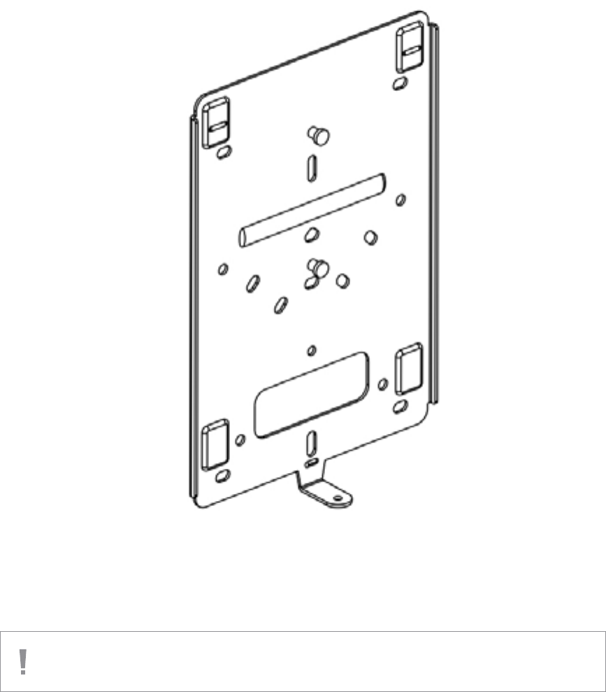
Mounting plate
6
Your MR26 mount plate has the following features:
MR26 cable access bay
Mount plate attachment
slots (2x)
Access point
mounting posts (2x)
Desk mount feet (4x)
Cable access bay
AC Adapter plug
Ethernet 0 port (10/100/1000)
Factory Reset Button
Various mounting holes
7
2.3 Security Features
The MR26 features multiple options for physically securing the access point after installation:
1. Security screw – The accessory kit includes screws that can be used to secure the access point to
the mount plate. Engaging the security screw prevents accidental dislodging and theft.
2. Kensington lock – The access point contains a hard point that allows it to be secured to any nearby
permanent structure using a standard Kensington lock.
2.4 Ethernet Ports
The MR26 features a Gigabit Ethernet RJ45 port that accepts 802.3af power (labeled
“Eth0, PoE”). This port should be used for uplink to your WAN connection.
2.5 Power Source Options
The MR26 access point can be powered using either the Meraki AC Adapter or 802.3af PoE Injector (both sold
separately) or a third-party 802.3af PoE switch.
2.6 Power Input/Rating
12Vdc, 1.5A / 48Vdc, 0.375A
2.7 Operating Temperature
0-40 Degrees C
2.8 Factory Reset Button
If the button is pressed and held for at least ve seconds and then released, the MR26 will reboot and be
restored to its original factory settings by deleting all conguration information stored on the unit.
8
2.9 UL 2043 Plenum rating
The MR26 meets the UL 2043 plenum-rating standard. This certies that the MR26 has adequate re resistance
and low smoke-emission characteristics to be mounted and operated in a building’s environmental air spaces,
such as above suspended ceilings in an oce environment.
3 Pre-Install Preparation
You should complete the following steps before going on-site to perform an installation.
3.1 Congure Your Network in Dashboard
The following is a brief overview only of the steps required to add an MR26 to your network. For detailed
instructions about creating, conguring and managing Meraki wireless networks, refer to the Meraki Cloud
Controller Manual (meraki.com/library/product).
1. Login to http://dashboard.meraki.com. If this is your rst time, create a new account.
2. Find the network to which you plan to add your APs or create a new network.
3. Add your APs to your network. You will need your Meraki order number (found on your invoice if you
ordered directly from Meraki) or the serial number of each AP, which looks like Qxxx-xxxx-xxxx, and is
found on the bottom of the unit. You will also need your Enterprise Cloud Controller license key, which you
should have received via email from shipping@meraki.com.
4. Go to the map / oor plan view and place each AP on the map by clicking and dragging it to the location
where you plan to mount it.
3.2 Check and Upgrade Firmware
To ensure your MR26 performs optimally immediately following installation, Meraki recommends that you
facilitate a rmware upgrade prior to mounting your MR26.
1. Attach your MR26 to power and a wired Internet connection. See p. 19 of this Hardware Installation
Guide for details.
2. The MR26 will turn on and the Power LED will glow solid orange. If the unit does not require a rmware
upgrade, the Power LED will turn white within thirty seconds.
* If the unit requires an upgrade, the Power LED will begin blinking orange until the upgrade is complete,
at which point the Power LED will turn solid white. You should allow about an hour for the rmware
upgrade to complete, depending on the speed of your internet connection.
3.3 Check and Congure Firewall Settings
If a rewall is in place, it must allow outgoing connections on particular ports to particular IP addresses.
The most current list of outbound ports and IP addresses can be found here:
http://tinyurl.com/y79une3
9
3.4 Assigning IP Addresses to MR26s
All gateway MR26s (MR26s with Ethernet connections to the LAN) must be assigned routable IP addresses.
These IP addresses can be dynamically assigned via DHCP or statically assigned.
3.4.1 Dynamic Assignment
When using DHCP, the DHCP server should be congured to assign a static IP address for each MAC address
belonging to a Meraki AP. Other features of the wireless network such as 802.1x authentication, may rely on the
property that the APs have static IP addresses.
3.4.2 Static Assignment
Static IPs are assigned using the local web server on each AP. The following procedure describes how to set
the static IP:
1. Using a client machine (e.g. a laptop), connect to the AP either wirelessly (by associating to any SSID
broadcast by the AP) or over a wired connection.
If using a wired connection, connect the client machine to the MR26 either through a PoE switch or a Meraki
PoE Injector. If using a PoE switch, plug an Ethernet cable into the MR26’s Ethernet jack, and the other end
into a PoE switch. Then connect the client machine over Ethernet cable to the PoE switch. If using a Meraki
PoE Injector, connect the MR26 to the “PoE” port of the Injector, and the client machine to the “LAN” port.
2. Using a web browser on the client machine, access the AP’s built-in web server by browsing to
http://my.meraki.com. Alternatively, browse to http://10.128.128.128.
3. Click on the “Static IP Conguration” tab. Log in. The default user name is “admin”. The default password is
the AP’s serial number, with hyphens included
4. Congure the static IP address, net mask, gateway IP address and DNS servers that this AP will use on its
wired connection.
5. If necessary, reconnect the AP to the LAN.
3.4.3 Static IP via DHCP Reservations
Instead of associating to each Meraki AP individually to congure static IP addresses, an administrator can assign
static IP addresses on the upstream DHCP server. Through “DHCP reservations”, IP addresses are “reserved” for the
MAC addresses of the Meraki APs. Please consult the documentation for the DHCP server to congure DHCP
reservations.
10
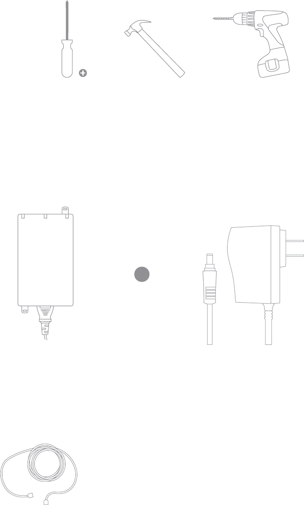
Phillips
screwdriver
Hammer Drill with 1/4”
(6.3mm) bits
3.6 Collect Additional Hardware for Installation
802.3af PoE power source (either PoE
switch or Meraki 802.3af PoE Injector)
Network cables with RJ45 connectors long
enough for your particular mounting location
3.5 Collect Tools
You will need the following tools to perform an installation:
AC Adapter
or
11
4 Installation Instructions
4.1 Choose Your Mounting Location
A good mounting location is important to getting the best performance out of your MR26 access point.
Keep the following in mind:
1. The device should have unobstructed line of sight to most coverage areas. For example, if installing
in an oce lled with workspaces divided by mid-height cubicle walls, installing on the ceiling or high
on a wall would be ideal.
2. Power over Ethernet supports a maximum cable length of 300 ft (100 m).
3. If being used in a mesh deployment, the MR26 should have line of sight to at least two other Meraki
devices. For more detailed instructions regarding access point location selection, reference the Meraki
Network Design Guide (meraki.com/library/product).
4.2 Install the MR26
For most mounting scenarios, the MR26 mount plate provides a quick, simple, and exible means of mounting
your device. The installation should be done in two steps. First, install the mount plate to your selected location.
Then, attach the MR26 to the mount plate.
4.2.1 Attach the Mount Plate
The MR26 mount plate can be used to install your access point in a wide range of scenarios: wall or solid
ceiling, below a drop ceiling, on various electrical junction boxes, or above a drop ceiling (in the plenum).
The mount plate contains a variety of hole patterns that are customized for each installation scenario. The
mounting template (included inbox with mount plate) should be used to drill holes for wall mounts and also to
identify the correct hole patterns in the mount plate that should be used for each type of mount.
The following images also show the hole patterns that should be used for each type of mount:
12
4.2.1.1 Wall or Solid Ceiling Mount Using Mount Plate
Using included screws, attach the mount plate to your mounting wall or ceiling.
It is recommended that the MR26 be mounted to a wall or solid ceiling using the mount plate for physical
security reasons.
If mounting your MR26 to a wall, skip to “Power the MR26“ on P. 20
13
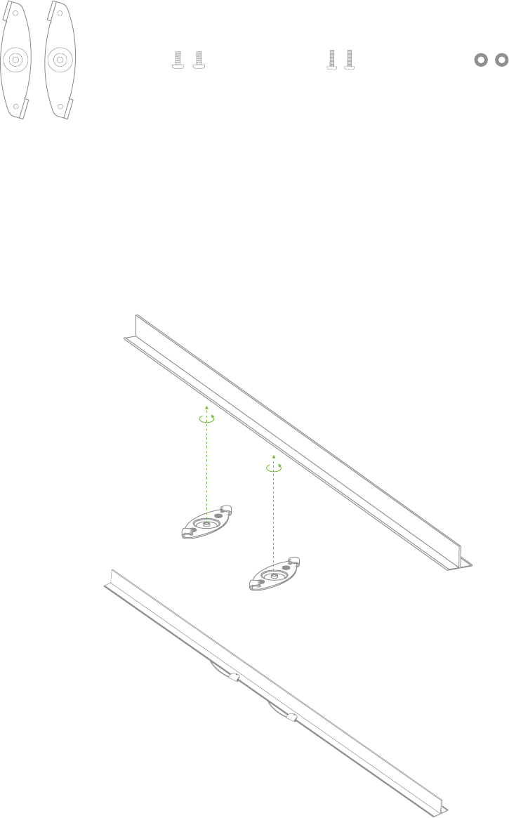
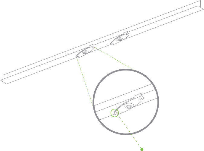
1. Attach the T-rail clips to the T-rail by rotating them and snapping them into place as shown.
The black foam pads should be compressed slightly after installation.
4.2.1.2 Drop Ceiling Mount Using Mount Plate
To mount your MR26 on a drop ceiling T-rail, use the included drop ceiling mounting accessory kit.
The accessory kit can be used to mount to most 9/16”, 15/16” or 1 ½” T-rails.
Dropped ceiling
mounting clips
with set screws
4-32 - 4 screws M2.5x9 - 2 screws
Only used for
recessed rail mount
(uncommon)
2 rubber spacers
Only used for
recessed rail mount
(uncommon)
The kit contains:
14
3. Tighten the set screws on the T-rail clips to secure the clips using a 5/64”(2 mm) hex key.
2. Using the dashed lines on the mount plate template as a guide, set the proper spacing of the
T-rail clips on the T-rail
Set screws (x4)
15
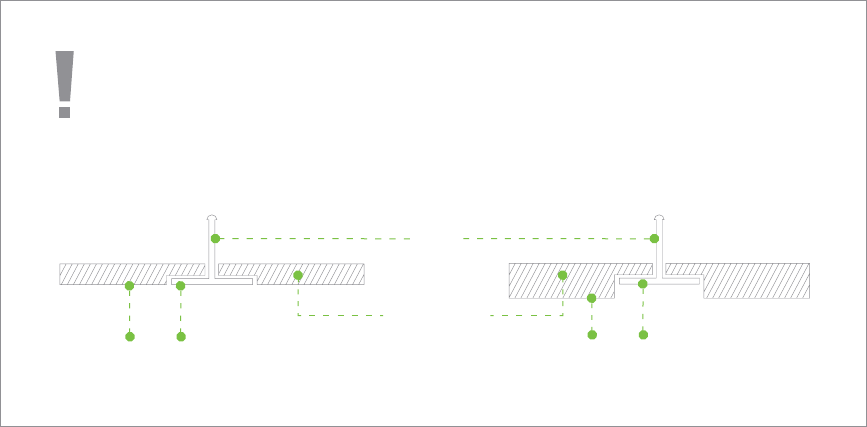
4. Attach the mount plate to the T-rail clips using the mount plate holes (marked with a “T“).
To select the correct set of mounting hardware to use, first determine whether you are
mounting to a “flush” or “recessed“ rail. (See below images for clarification)
Flush T-rail Recessed T-rail
T-rail ush with tiles T-rail recessed from tiles
Ceiling tiles
T-rail
16
4.2.1.3 Electrical Junction Box Mount Using Mount Plate
The MR26 can be mounted to a 4” square cable junction box, a 3.5 or 4” round cable junction box, or
various U.S. and European outlet boxes (mounting screws are not included).
Using appropriate mounting hardware for your specific type of junction box, attach the mount plate to
the junction box.
17
4.2.2 Power the MR26
If mounting to an electrical junction box, feed the Ethernet cable through the cable access hole in the Mount Plate:
If mounting to a wall or ceiling, the Ethernet cable will feed through the cable slot on bottom of the MR26.
18
4.2.2.1 Powering the MR26 with the Meraki AC Adapter (sold separately)
1. Plug the power cord into the MR26 and the other end into a wall outlet.
2. Plug an Ethernet cable that is connected to an active Ethernet connection into the Eth0 port on the MR26.
4.2.2.2 Powering the MR26 with the Meraki 802.3af Power over Ethernet Injector (sold separately)
1. Plug the power cord into the PoE Injector and the other end into wall power.
2. Plug an Ethernet cable that is connected to an active Ethernet connection into the “IN“ port on the injector.
3. Route Ethernet cable from the “OUT“ port on the injector to the Eth0 port in the cable bay of the MR26.
19
4.2.3 Mount the MR26
4.2.2.3 Powering the MR26 with an 802.3af Power over Ethernet Switch
Route Ethernet cable from a port on an active 802.3af PoE switch to the Eth0 port in the bay of the MR26.
The MR26 is Gigabit Ethernet-capable. To maximize device performance, a Gigabit-capable
switch should be used.
20
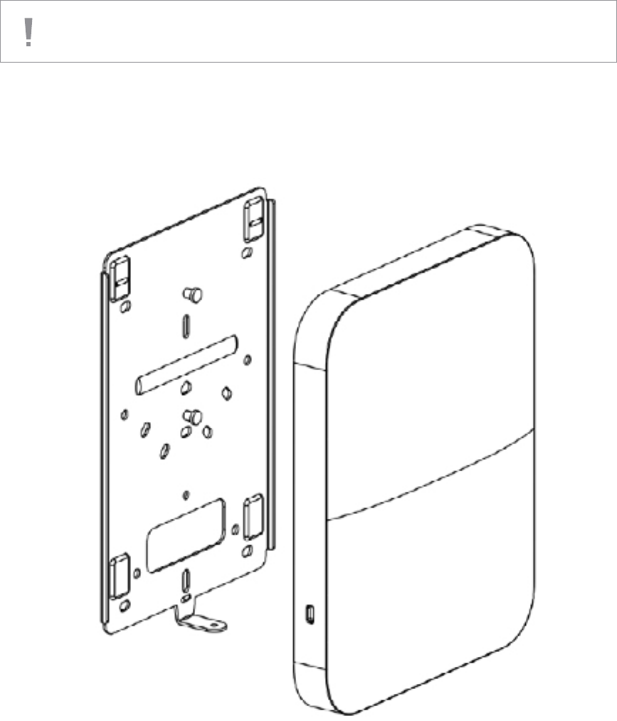
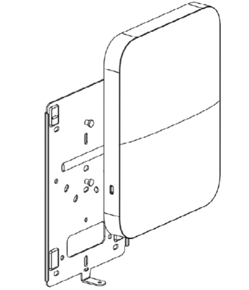
4.2.3.2 Assemble MR26 to the Mount Plate
(This section applies to wall and/or solid ceiling, drop ceiling or electrical junction box mount
where you have already installed the mount plate.)
Insert the top latch on the mount plate into the top mount plate attachment slots on the back of the device. Rotate the
bottom of the unit into the bottom ount plate attachment slot. The unit will click into place.
21
4.2.3.3 Desk or Shelf Mount
The MR26 can be placed on a desk or shelf resting on the non-scratch rubber feet. The mount plate is not
necessary for a desk or shelf mounting.
22
4.3 Secure the MR26
Depending on your mounting environment, you may want to secure the MR26 to its mount location. Your MR26
can be secured in several ways. If the MR18 has been installed using the mount plate, it can be secured via security
screw (Torx and phillips head security screws are included; choose one), and/or Kensington lock. If the mount
plate was not used, the MR26 can still be secured using a Kensington lock.
4.3.1 Security Screw
Install the security screw in the lower mount plate tab.
4.3.2 Kensington Lock
Attach a Kensington lock cable to the access point at the hard point on the side of the device.
Attach the other end of the cable to a secure location, such as a pipe or building xture.
23
4.4 Verify Device Functionality and Test Network Coverage
1. Check LEDs
The LED should be solid blue when it is on and serving clients (and blue if it is on and no clients are being served).
If it is blinking blue, the rmware is automatically upgrading and the LED should turn green when the upgrade is completed
(normally in under a few minutes).
Note: Your MR26 must have an active route to the Internet to check and upgrade its rmware.
2. Verify access point connectivity
Use any 802.11 client device to connect to the MR26 and verify proper connectivity using the client’s web browser.
3. Check network coverage
Conrm that you have good signal strength throughout your coverage area. You can use the signal strength meter
on a laptop, smart phone, or other wireless device.
5 Troubleshooting
Reference the Meraki knowledge base at http://meraki.com/support/knowledge_base for additional information and
troubleshooting tips.
6 Regulatory
FCC Compliance Statement
This device complies with part 15 of the FCC rules. Operation is subject to the following two conditions: (1) This device
may not cause harmful interference, and (2) this device must accept any interference received, including interference
that may cause undesired operation.
FCC Interference Statement
This equipment has been tested and found to comply with the limits for a Class B digital device, pursuant to part 15 of
the FCC Rules. These limits are designed to provide reasonable protection against harmful interference in a residential
installation. This equipment generates, uses and can radiate radio frequency energy and, if not installed and used in
ac cordance with the instructions, may cause harmful interference to radio communications. However, there is no
guarantee that interference will not occur in a particular installation. If this equipment does cause harmful interference
to radio or television reception, which can be determined by turning the equipment o and on, the user is encouraged
to correct the interference by one of the following measures:
•Reorientorrelocatethereceivingantenna.
•Increasetheseparationbetweentheequipmentandreceiver.
•Connecttheequipmentintoanoutletonacircuitdierentfromwhichthereceiverisconnected.
•Consultthedealeroranexperiencedradio/TVtechnicianforhelp.
FCC Caution
Any changes or modications no expressly approved by Meraki could void the user’s authority to operate this
equipment. This Transmitter must not be co-located or operation in conjunction with any other antenna or transmitter.
FCC Radiation Exposure Statement
This equipment complies with FCC radiation exposure limits set forth for an uncontrolled environment. This equipment
should be installed and operated with minimum distance 20 cm between the radiator and your body. This transmitter
must not be co-located or operating in conjunction with any other antenna or transmitter.
IEEE 802.11b or 802.11g operation of this product in the USA is rmware-limited to channels 1 through 11.
If the device is going to be operated in the 5.15 - 5.25 frequency range, then it is restricted to indoor environment only.
This device meets all other requirements specied in Part 15E, Section 15.407 of the FCC Rules.

24
Copyright
© 2013 Cisco Systems, Inc. All rights reserved.
Trademarks
Cisco Systems® is a registered trademark of Cisco Systems, Inc.

25
www.ciscosystems.com
Cisco Systems, Inc.
170 West Tasman Drive
San Jose, CA 95134 USA