Cisco Systems 60047015 802.11a/b/g/n/ac Wireless Router User Manual UDX 60047015 Setup Guide
Cisco Systems 802.11a/b/g/n/ac Wireless Router UDX 60047015 Setup Guide
UDX-60047015_Setup Guide
Meraki MX65W-HW Installation Guide
This document describes how to install and set up the MX65W-HW security appliance.
Additional reference documents are available online at: www.meraki.com/library/products.
MX65W-HW Overview
The Meraki MX65W-HW (model: MX65W-HW) is an enterprise security appliance designed
for distributed deployments that require remote administration. It is ideal for network
administrators who demand both ease of deployment and a state-of-the-art feature set.
This appliance provides the following new features:
• 2.4-Ghz (2 spatial streams) and 5-GHz (2 spatial streams) radios for
802.11abgn/ac support.
• USB port, to support approved 3G/4G cards for failover to cellular networks.
• Support for 10 LAN connections (2 of 10 offer 802.3at support)
• Wall screws and anchors for mounting drywall surface, either vertically or
horizontally
MX65W-HW Operational Temperature: 32 o F to 104 o F (0 o C to 40 o C)
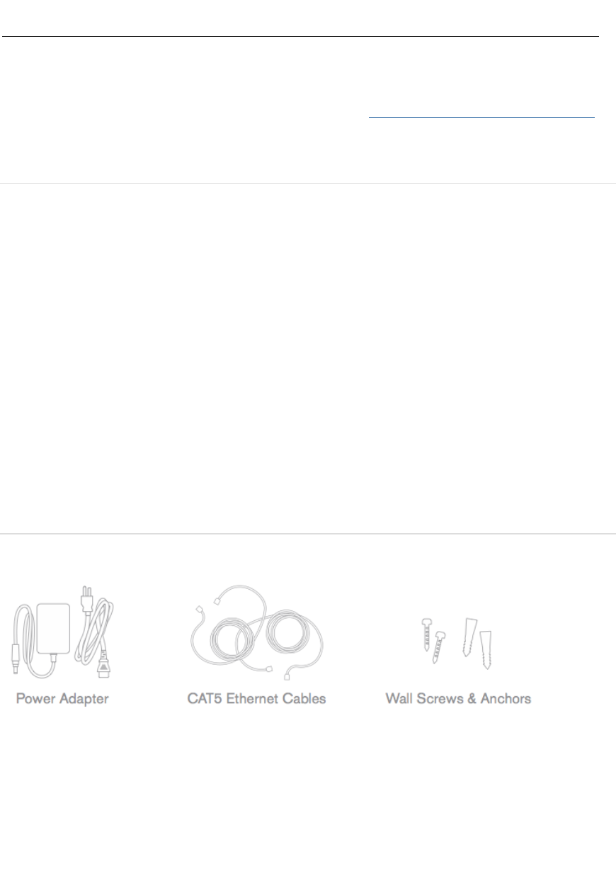
Package Contents
In addition to the MX65W-HW, the following are provided.
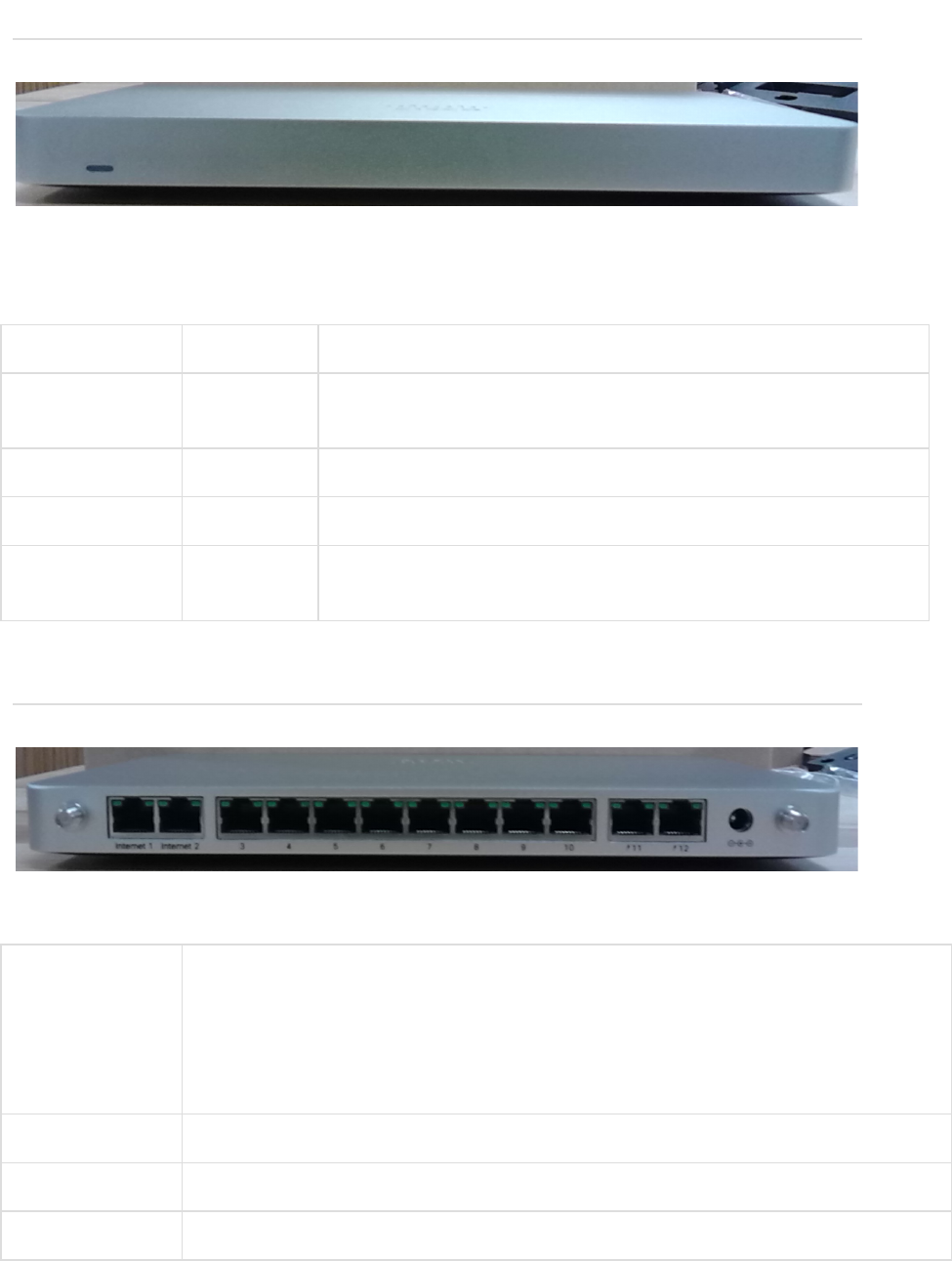
The MX65W-HW front panel
!
Ports and Status Indicators
The MX65W-HW uses a single LED to inform the user of the device's status.
Function
LED Status
Meaning
Power Up/Boot
Solid
Orange
Power is applied
Connecting
Rainbow
Device in process of connecting to the Meraki Dashboard
Connected
Solid White
Fully operational
Upgrading
Flashing
White
During boot or no WAN link
The MX65W-HW back panel
!
Additional functions on the back panel are described below, from left to right.
LAN ports
Ten (Ports 3 through 12) provide connectivity to computers, printers, access
points, or Ethernet switches. Two of these ten (Ports 11 and 12) also provide
PoE+ (802.3at) support.
Two LEDs -- one for activity, another for connectivity. A steady green LED
indicates bidirectional connectivity while a flashing green LED indicates traffic.
Internet ports
Two ports provide connectivity to the WAN.
Power input
Designed for use only with the unit’s power supply.
Antenna ports
Two RP-SMA ports for dipole antennas (two antennas included)
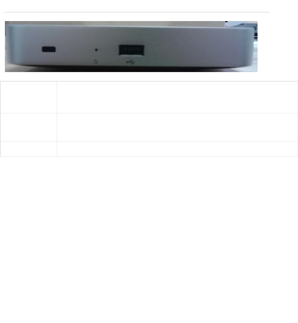
The MX65W-HW side panel
!
!
!
Restore button
Insert a paper clip if a reset is required.
• A brief, momentary press: To delete a downloaded configuration and reboot.
• Press and hold for more than 10 sec: To force the unit into a full factory reset.
Kensington
Security Slot
The slot is a portion of the Kensington lock system and is compatible with any
Kensington cable.
USB port
USB 2.0 for 3G/4G wireless cards.
!
!
!
!
!
!
!
!
!
!
!
!
!
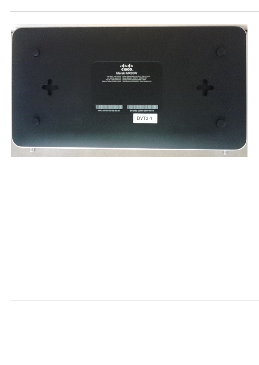
The MX65W-HW bottom panel
!
Please note that the serial number is located on the product label, which is located on the
bottom of the MX65W-HW. The blank region in the center of the label will be populated with
regulatory marks on commercial units.
Mounting hardware
The supplied wall screws and anchors allow you to mount the appliance on a drywall
surface, either vertically or horizontally. The distance between the holes you drill should be
165 mm.
• For mounting on drywall, use a ¼-in drill bit, then insert the plastic and screw assemblies.
• For mounting on wood or a similar surface, use only the screws.
• Allow the heads of the screws to stick out far enough to be inserted securely into the back
of the appliance.
Connecting to the WAN
All Meraki MX devices must have an IP address. This section describes how to configure
your local area network before you deploy it. A local management web service, running on
the appliance, is accessed through a browser running on a client PC. This web service is
used for configuring and monitoring basic ISP/WAN connectivity.

Setting up a static IP address
To ensure that the client PC is redirected to the local web service in the following step, you
must disable all other network services (e.g., Wi-Fi) on your client machine.
Do the following to configure basic connectivity and other networking parameters:
1. Using a client machine such as a laptop, connect to one of the ten LAN ports of the MX.
2. Using a browser on the client machine, access the appliance's built-in web service by
browsing to http://setup.meraki.com. (You do not have to be connected to the Internet to
reach this address)
3. Click Uplink configuration under the Local status tab.
4. Choose Static for the IP Assignment option.
5. Enter the IP address, subnet mask, default gateway IP and DNS server information.
Setting up a DHCP IP address
By default all MX devices are configured to DHCP from upstream WAN / ISP servers. Simply
plug one of the MX's WAN / Internet ports into your upstream circuit and wait a few minutes
for the unit to negotiate a DHCP address.
Icon
When the WAN connection is fully enabled, the Internet 1 or 2 LED 1 will turn green.
Additional settings
Please note that all these settings below are accessible only via the local management
console.
Setting VLANs
If your WAN uplink is on a trunk port, choose VLAN tagging > Use VLAN tagging and enter
the appropriate value for VLAN ID for your network.
Setting PPPoE
PPPoE authentication may be required if you are connecting the MX to a DSL circuit. You
need to know your authentication option and credentials (supplied by your ISP) in order to
complete these steps.
• Choose Connection Type > PPPoE.
• Select your Authentication option.
• If you select Use authentication, enter appropriate values for Username and Password.

Web proxy settings
These settings take effect if the MX device has to fall back to using HTTP to contact the
Cloud Controller. By default, web proxy is disabled. To enable web proxy, do the following:
• Choose Web proxy > Yes.
• Enter values as appropriate for Hostname or IP and Port.
• If you require authentication, choose Authentication > Use authentication, and enter
appropriate values for Username and Password.
To apply all configuration settings to the appliance, be sure to click Save Settings at the
bottom of the page.
Configuring physical link settings
To configure physical link settings on the Ethernet ports, click Local status > Ethernet
configuration. You can enable half duplex, full duplex, and auto-negotiation, as well as set
10- or 100-Mbps data rates.
Regulatory
FCC Compliance Statement
This device complies with part 15 of the FCC rules. Operation is subject to the following two
conditions: (1) This device may not cause harmful interference, and (2) this device must
accept any interference received, including interference that may cause undesired
operation.
FCC Interference Statement
This equipment has been tested and found to comply with the limits for a Class B digital
device, pursuant to part 15 of the FCC Rules. These limits are designed to provide
reasonable protection against harmful interference in a residential installation. This
equipment generates, uses and can radiate radio frequency energy and, if not installed and
used in accordance with the instructions, may cause harmful interference to radio
communications. However, there is no guarantee that interference will not occur in a
particular installation. If this equipment does cause harmful interference to radio or television
reception, which can be determined by turning the equipment off and on, the user is
encouraged to correct the interference by one of the following measures:
• Reorient or relocate the receiving antenna.
• Increase the separation between the equipment and receiver.
• Connect the equipment into an outlet on a circuit different from which the receiver is
connected.
• Consult the dealer or an experienced radio/TV technician for help.
FCC Caution
Any changes or modifications no expressly approved by Cisco could void the user’s
authority to operate this equipment. This Transmitter must not be co-located or operation in
conjunction with any other antenna or transmitter.
FCC Radiation Exposure Statement
This equipment complies with FCC radiation exposure limits set forth for an uncontrolled
environment. This equipment should be installed and operated with minimum distance 20
cm between the radiator and your body. This transmitter must not be co-located or
operating in conjunction with any other antenna or transmitter.
IEEE 802.11b or 802.11g operation of this product in the USA is firmware-limited to
channels 1 through 11.
If the device is going to be operated in the 5.15 - 5.25 frequency range, then it is restricted
to indoor environment only. This device meets all other requirements specified in Part 15E,
Section 15.407 of the FCC Rules.
Industry Canada Statement
This device complies with RSS-247 of the Industry Canada Rules. Operation is subject to the
following two conditions: (1) This device may not cause harmful interference, and (2) this
device must accept any interference received, including interference that may cause
undesired operation.
Ce dispositif est conforme à la norme CNR-247 d’Industrie Canada applicable aux appareils
radio exempts de licence. Son fonctionnement est sujet aux deux conditions suivantes: (1) le
dispositif ne doit pas produire de brouillage préjudiciable, et (2) ce dispositif doit accepter
tout brouillage reçu, y compris un brouillage susceptible de provoquer un fonctionnement
indésirable.
Industry Canada Caution
(i) the device for operation in the band 5150-5250 MHz is only for indoor use to reduce the
potential for harmful interference to co-channel mobile satellite systems;
(ii) high-power radars are allocated as primary users (i.e. priority users) of the bands 5250-
5350 MHz and 5650-5850 MHz and that these radars could cause interference and/or
damage to LE-LAN devices.
Avertissement:
(i) les dispositifs fonctionnant dans la bande 5 150-5 250 MHz sont réservés uniquement
pour une utilisation à l’intérieur a n de réduire les risques de brouillage préjudiciable aux
systèmes de satellites mobiles utilisant les mêmes canaux;
(ii) De plus, les utilisateurs devraient aussi être avisés que les utilisateurs de radars de haute
puissance sont désignés utilisateurs principaux (c.-à-d., qu’ils ont la priorité) pour les
bandes 5 250-5 350 MHz et 5 650-5 850 MHz et que ces radars pourraient causer du
brouillage et/ou des dommages aux dispositifs LAN-EL.
Industry Canada Radiation Exposure Statement
This equipment complies with IC radiation exposure limits set forth for an uncontrolled
environment. This equipment should be installed and operated with minimum distance 20
cm between the radiator & your body.
Déclaration d’exposition aux radiations
Cet équipement est conforme aux limites d’exposition aux rayonnements IC établies pour un
environnement non con trôlé. Cet équipement doit être installé et utilisé avec un minimum
de 20 cm de distance entre la source de rayonnement et votre corps.