Cisco Systems 60053010 802.11a/b/g/n/ac Wireless Security Appliance User Manual Z3 Installation Guide Internal
Cisco Systems 802.11a/b/g/n/ac Wireless Security Appliance Z3 Installation Guide Internal
User Manual
Z3 Installation Guide [Internal]
This document describes how to install and set up the Z3 teleworker gateway. Additional reference documents are
available online at: www.meraki.com/library/products.
Z3 Overview
The Meraki Z3 is an enterprise teleworker gateway designed for telecommuting employees and IT staff. It is also a great
all-in-one device to test the capabilities of Meraki's cloud-managed networking. This gateway provides the following
features:
• Support for four LAN connections
• Dual-concurrent 802.11ac radios for wireless connections
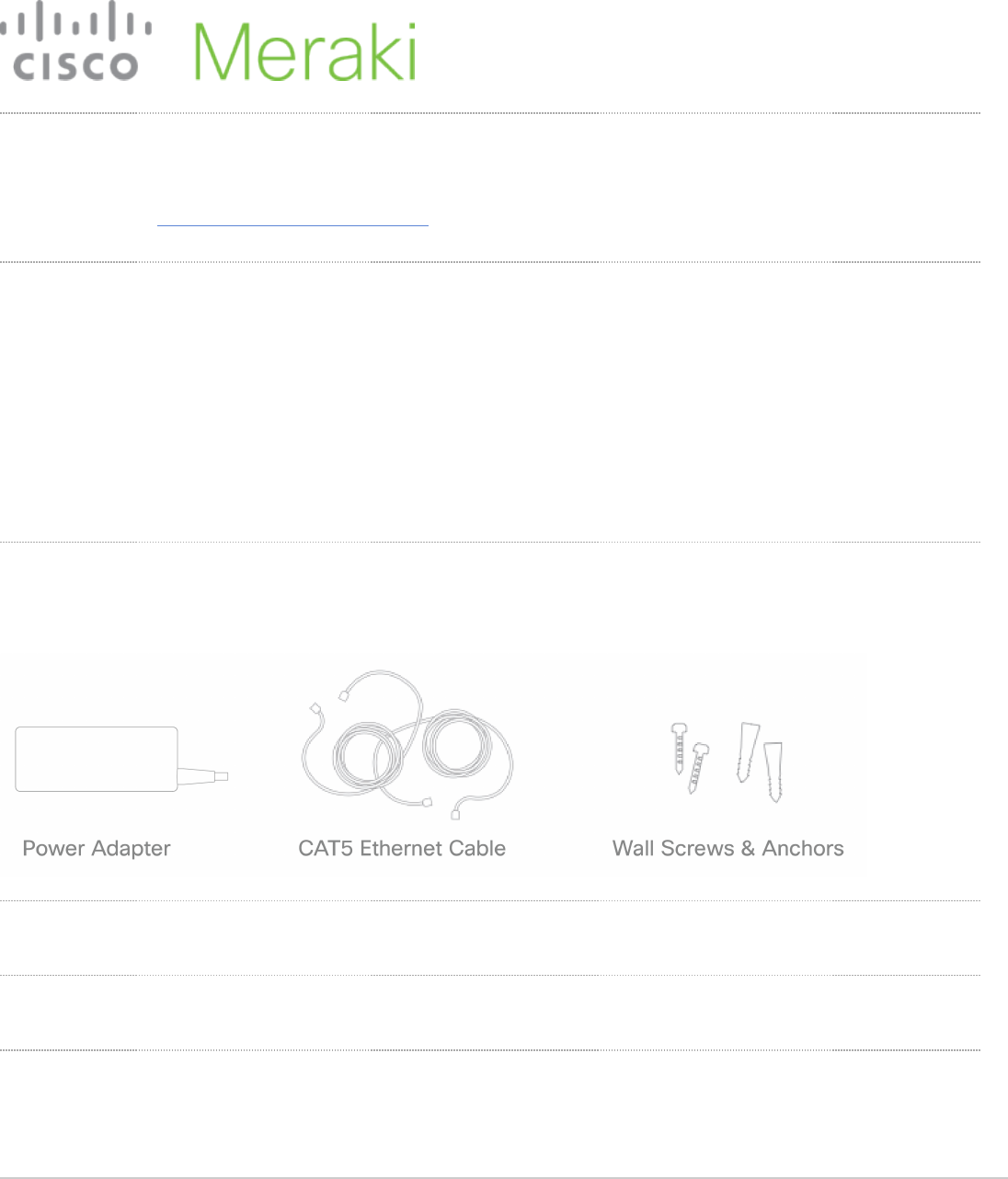
• Wall screws and anchors for mounting drywall surface, either vertically or horizontally
Package contents
In addition to the Z3, the following are provided.
1
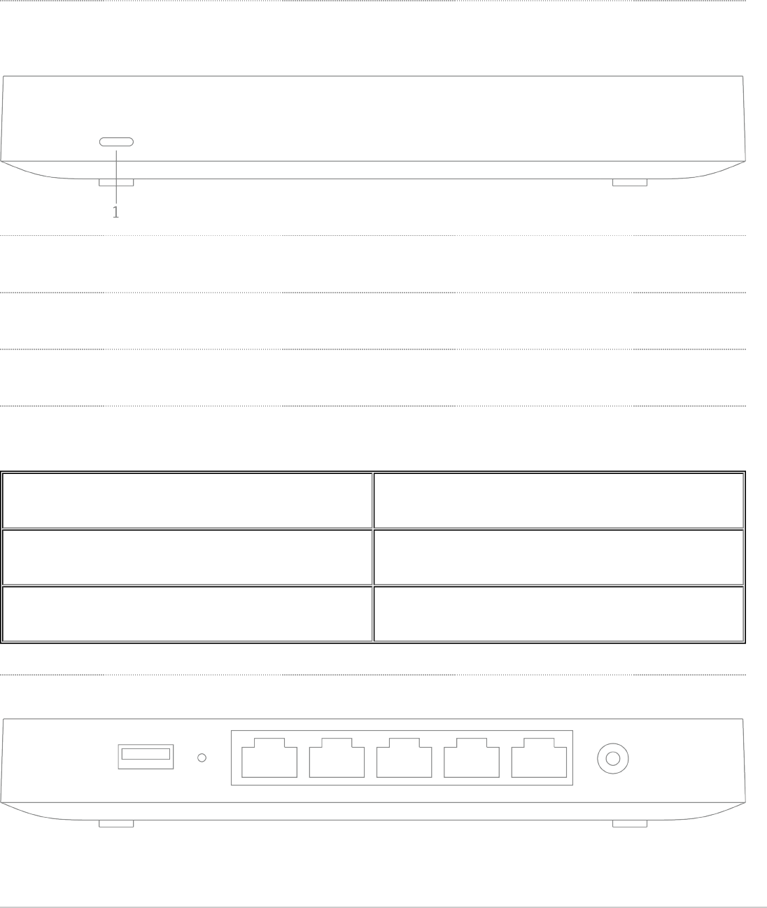
The Z3 front panel
Ports and Status Indicators
The Z3 uses a single LED to inform the user of the device's status.
LED Status Meaning
Flashing white Operation in progress
Solid white Power is applied, Fully operational
The Z3 back panel
Additional functions on the back panel are described below, from left to right.
2
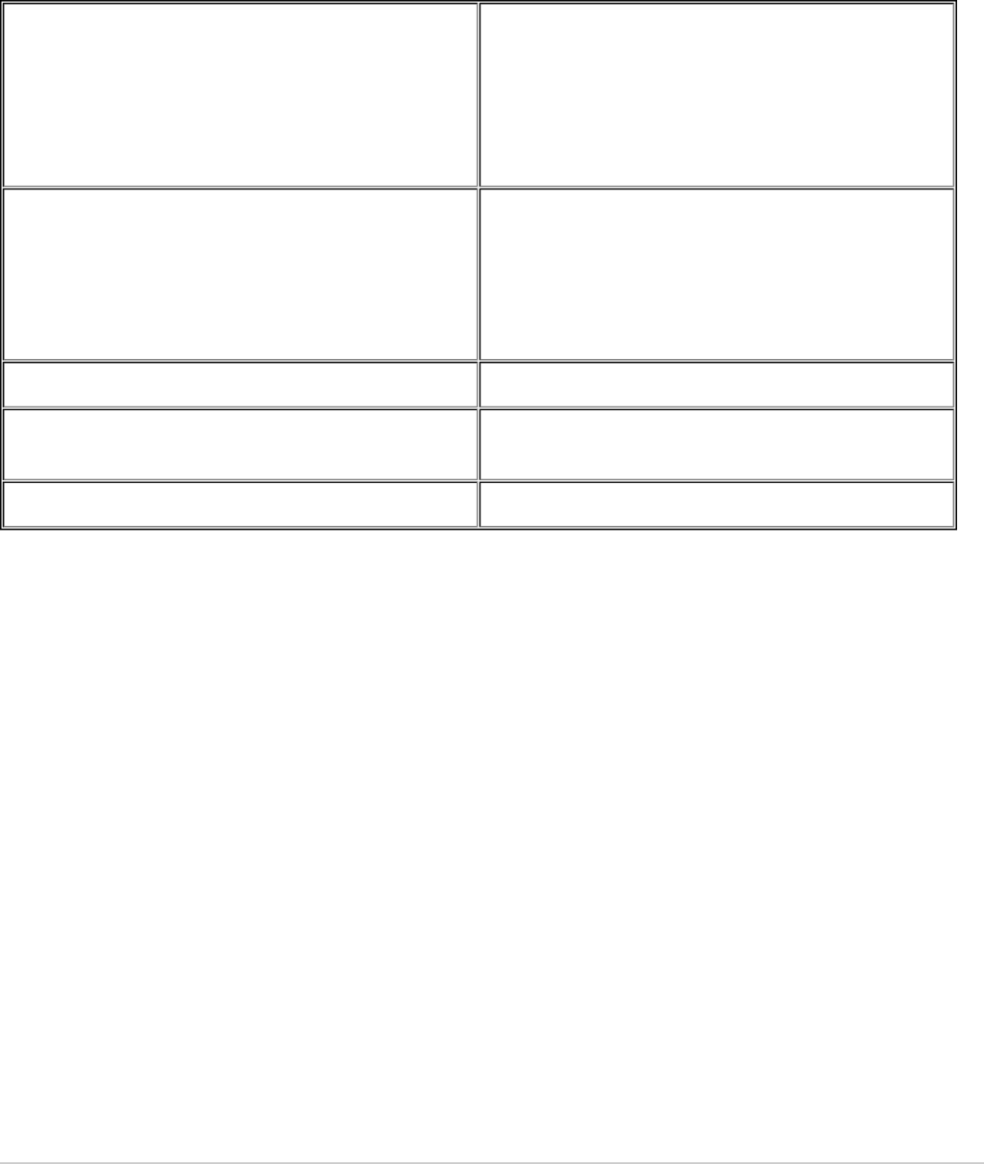
Reset button
Insert a paper clip if a reset is required.
• A brief, momentary press: To delete a downloaded
configuration and reboot.
• Press and hold for more than 10 sec: To force the
unit into a full factory reset.
LAN ports
These 4 ports provide connectivity to computers,
printers, access points, or Ethernet switches.
A steady green LED indicates bidirectional connectivity,
and flashing green indicates traffic.
WAN / Internet port Provides connectivity to the WAN.
USB port USB 2.0 for 3G/4G wireless cards
Power input Designed for use only with the unit’s power supply.
3

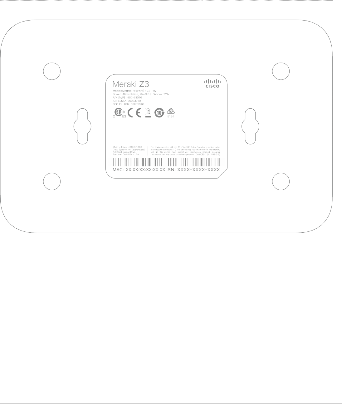
Please note that the serial number is located on the product label at the bottom panel of Z3
Mounting hardware
The supplied wall screws and anchors allow you to mount the gateway on a drywall surface, either vertically or
horizontally.
• For mounting on drywall, use a ¼-in drill bit, then insert the plastic and screw assemblies.
• For mounting on wood or a similar surface, use only the screws.
• Allow the heads of the screws to stick out far enough to be inserted securely into the back of the gateway.
Connecting to WAN
All Meraki Z3 devices must have an IP address. This section describes how to configure your local area network before
you deploy it. A local management web service, running on the gateway, is accessed through a browser running on a
client PC. This web service is used for configuring and monitoring basic ISP/WAN connectivity.
5
Setting up a static IP address
Do the following to configure basic connectivity and other networking parameters:
1. Using a client machine such as a laptop, connect to one of the four LAN ports of the Z3.
2. Using a browser on the client machine, access the gateway's built-in web service by browsing to
http://setup.meraki.com. (You do not have to be connected to the Internet to reach this address)
3. Click Uplink configuration under the Local status tab. The default credentials use the device serial number as
the username, with a blank password field.
4. Choose Static for the IP Assignment option.
5. Enter the IP address, subnet mask, default gateway IP and DNS server information.
Setting up a DHCP IP address
By default all Z3 devices are configured to DHCP from upstream WAN / ISP servers. Simply plug the Z3's WAN /
Internet port to your upstream circuit and wait a few minutes for the unit to negotiate a DHCP address.
Additional settings
Setting VLANs
If your WAN uplink is on a trunk port, choose VLAN tagging > Use VLAN tagging and enter the appropriate value for
VLAN ID for your network.
Setting PPPoE
PPPoE authentication may be required if you are connecting Z3 device to a DSL circuit. You need to know your
authentication option and credentials (supplied by your ISP) in order to complete these steps.
• Choose Connection Type > PPPoE.
• Select your Authentication option.
• If you select Use authentication, enter appropriate values for Username and Password.
Web proxy settings
These settings take effect if the Z3 device has to fall back to using HTTP to contact the Cloud Controller. By default, web
proxy is disabled. To enable web proxy, do the following:
To ensure that the client PC is redirected to the local web service in the following step, you must disable all
other network services (ex: wi-fi) on your client machine.
When the WAN connection is fully enabled, the device's front LED will be solid white.
6

• Choose Web proxy > Yes.
• Enter values as appropriate for Hostname or IP and Port.
• If you require authentication, choose Authentication > Use authentication, and enter appropriate values for
Username and Password.
Configuring physical link settings
To configure physical link settings on the Ethernet ports, click Local status > Ethernet configuration. You can enable
half duplex, full duplex, and autonegotiation, as well as set 10- or 100-Mbps data rates.
Power efficiency modes
The Meraki Z3 Teleworker Appliance has an off mode and a networked standby or efficient idle mode, both with power
consumption less than 12W.
In off mode, the power consumption is a measured 0.3W. In the networked standby or efficient idle mode, the power
consumption is under that of full operation mode, which is a measured 6.6W. This mode is initiated after treating the last
payload packets.
To activate and/or deactivate wireless network ports, you may use the physical on/off switch or deactivate through the
Meraki Dashboard.
Regulatory
This equipment is for indoor use only and the PoE device is considered unlikely to connect to an Ethernet network with
outside plant routing, including campus environments.
FCC Compliance Statement
This device complies with part 15 of the FCC rules. Operation is subject to the following two conditions: (1) This device
may not cause harmful interference, and (2) this device must accept any interference received, including interference
that may cause undesired operation.
FCC Interference Statement
To apply all configuration settings to the gateway, be sure to click Save Settings at the bottom of the page.
7

This equipment has been tested and found to comply with the limits for a Class B digital device, pursuant to part 15 of
the FCC Rules. These limits are designed to provide reasonable protection against harmful interference in a residential
installation. This equipment generates, uses and can radiate radio frequency energy and, if not installed and used in
accordance with the instructions, may cause harmful interference to radio communications. However, there is no
guarantee that interference will not occur in a particular installation. If this equipment does cause harmful interference to
radio or television reception, which can be determined by turning the equipment off and on, the user is encouraged to
correct the interference by one of the following measures:
• Reorient or relocate the receiving antenna.
• Increase the separation between the equipment and receiver.
• Connect the equipment into an outlet on a circuit different from which the receiver is connected.
• Consult the dealer or an experienced radio/TV technician for help.
FCC Caution
Any changes or modifications no expressly approved by Meraki could void the user’s authority to operate this
equipment. This Transmitter must not be co-located or operation in conjunction with any other antenna or transmitter.
FCC Radiation Exposure Statement
This equipment complies with FCC radiation exposure limits set forth for an uncontrolled environment. This equipment
should be installed and operated with minimum distance 20 cm between the radiator and your body. This transmitter
must not be co-located or operating in conjunction with any other antenna or transmitter.
IEEE 802.11b or 802.11g operation of this product in the USA is firmware-limited to channels 1 through 11.
If the device is going to be operated in the 5.15 - 5.25 frequency range, then it is restricted to indoor environment only.
This device meets all other requirements specified in Part 15E, Section 15.407 of the FCC Rules.
Industry Canada Statement
This device complies with RSS-247 of the Industry Canada Rules. Operation is subject to the following two conditions:
(1) This device may not cause harmful interference, and (2) this device must accept any interference received, including
interference that may cause undesired operation.
Ce dispositif est conforme à la norme CNR-247 d’Industrie Canada applicable aux appareils radio exempts de licence.
Son fonctionnement est sujet aux deux conditions suivantes: (1) le dispositif ne doit pas produire de brouillage
8

préjudiciable, et (2) ce dispositif doit accepter tout brouillage reçu, y compris un brouillage susceptible de provoquer un
fonctionnement indésirable.
Industry Canada Caution
(i) the device for operation in the band 5150-5250 MHz is only for indoor use to reduce the potential for harmful
interference to co-channel mobile satellite systems;
(ii) high-power radars are allocated as primary users (i.e. priority users) of the bands 5250-5350 MHz and 5650-5850
MHz and that these radars could cause interference and/or damage to LE-LAN devices.
Avertissement:
(i) les dispositifs fonctionnant dans la bande 5 150-5 250 MHz sont réservés uniquement pour une utilisation à l’intérieur
afin de réduire les risques de brouillage préjudiciable aux systèmes de satellites mobiles utilisant les mêmes canaux;
(ii) De plus, les utilisateurs devraient aussi être avisés que les utilisateurs de radars de haute puissance sont désignés
utilisateurs principaux (c.-à-d., qu’ils ont la priorité) pour les bandes 5 250-5 350 MHz et 5 650-5 850 MHz et que ces
radars pourraient causer du brouillage et/ou des dommages aux dispositifs LAN-EL.
Industry Canada Radiation Exposure Statement
This equipment complies with IC radiation exposure limits set forth for an uncontrolled environment. This equipment
should be installed and operated with minimum distance 20 cm between the radiator & your body.
Déclaration d’exposition aux radiations
Cet équipement est conforme aux limites d’exposition aux rayonnements IC établies pour un environnement non con
trôlé. Cet équipement doit être installé et utilisé avec un minimum de 20 cm de distance entre la source de rayonnement
et votre corps.
NCC Compliance Statement
低功率電波輻射性電機管理辦法低功率電波輻射性電機管理辦法
第十二條 經型式認證合格之低功率射頻電機,非經許可,公司、商號或使用者均不得擅自變更頻率、加大功率或變更原設
計之特性及功能。
9

第十四條 低功率射頻電機之使用不得影響飛航安全及干擾合法通信;經發現有干擾現象時,應立即停用,並改善至無干擾
時方得繼續使用。
前項合法通信,指依電信法規定作業之無線電通信。
低功率射頻電機須忍受合法通信或工業、科學及醫療用電波輻射性電機設備之干擾。
電磁波曝露量MPE標準值1mW/cm2,本產品使用時建議應距離人體 20 cm。
1. 使用此產品時應避免影響附近雷達系統之操作。
2. 高增益指向性天線只得應用於固定式點對點系統。
10