Cisco Systems 60063010 Wireless 802.11 a/b/g/n/ac Access Point User Manual MR42 Installation Guide
Cisco Systems Wireless 802.11 a/b/g/n/ac Access Point MR42 Installation Guide
Contents
- 1. UDX-60063010_Installation Guide
- 2. UDX-60063010_Regulatory Booklet_Rev5
UDX-60063010_Installation Guide
J
J
J
2
MR42E
MR42E
3
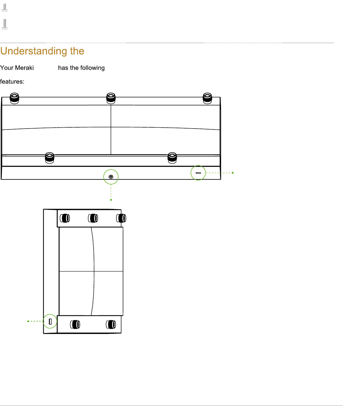
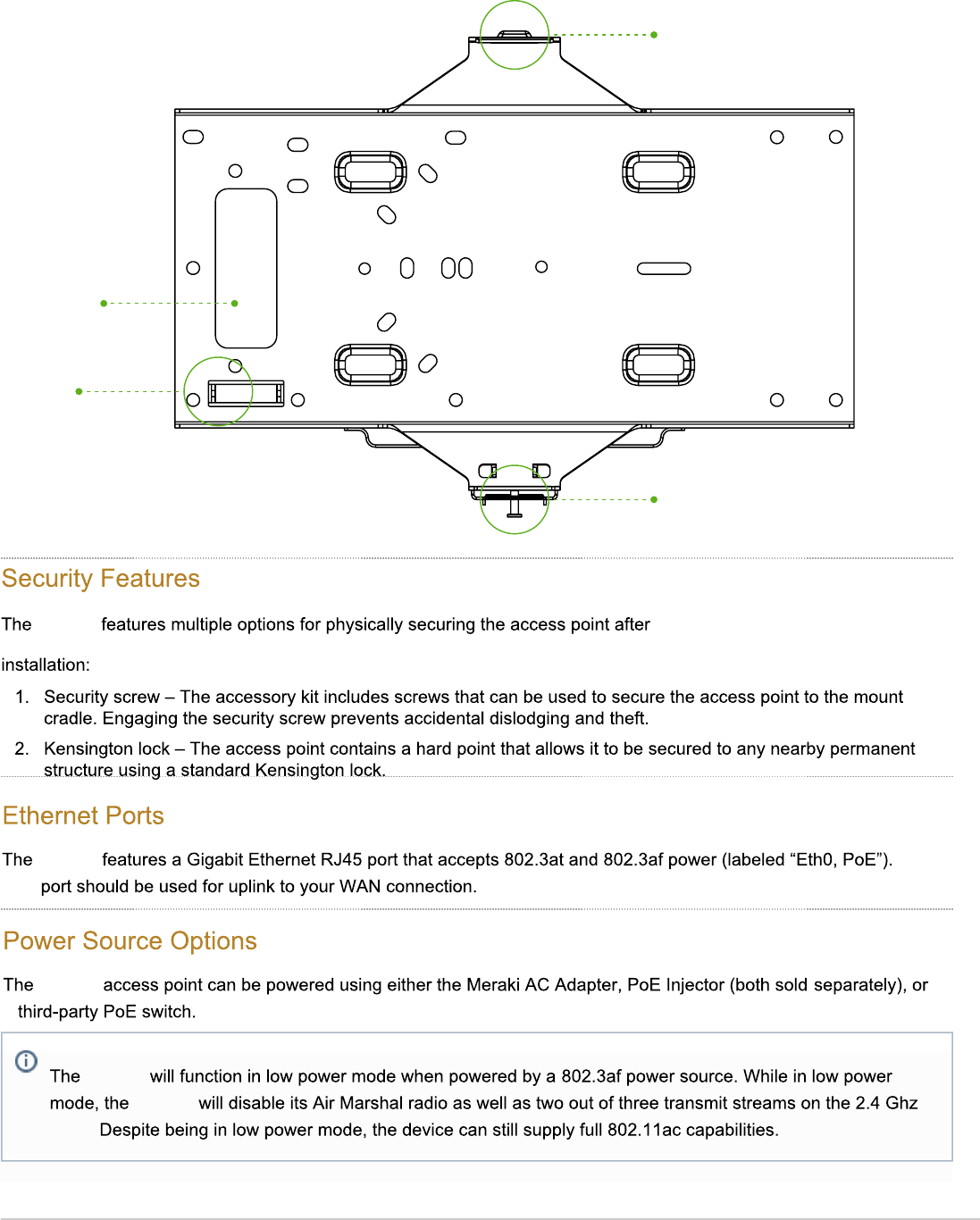
Security screw hole
LED indicator
Kensington lock
hard point
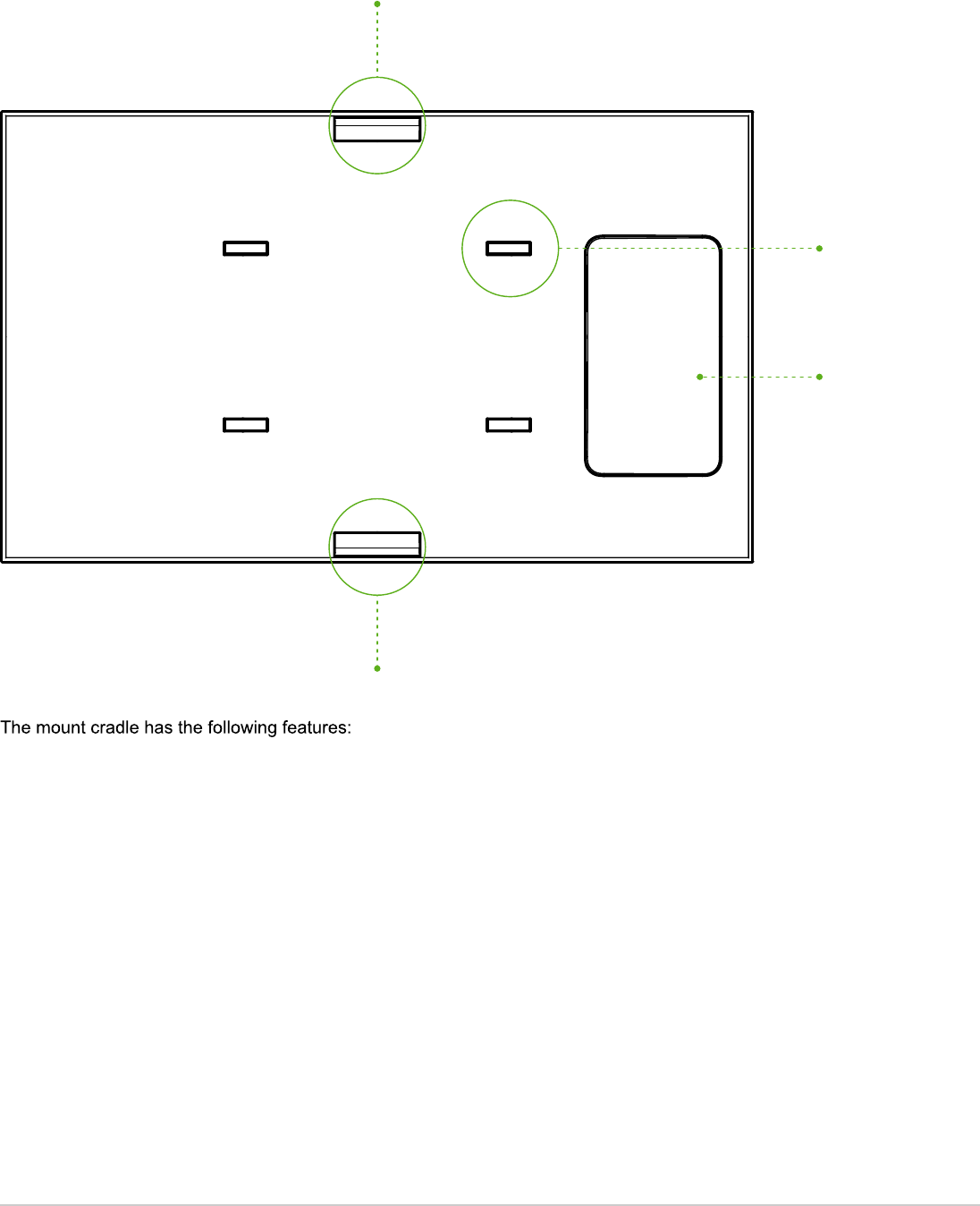
4
Mount cradle
attachment point
Desk mount feet
Cable access
bay
Mount cradle
attachment point
MR42E
MR42E
)78B
MR42E
0
MR42E
MR42E
10=3
5
Cable access
slot
Level tool
Mounting tab
(security screw shown)
Mounting tab

Factory Reset Button
If the button is pressed and held for at least five seconds and then released, the MR42E will reboot and be restored to
its original factory settings by deleting all configuration information stored on the unit.
LED Indicators and Run Dark Mode
Your MR42E is equipped with a multi-color LED light on the front of the unit to convey information about
system functionality and performance:
• Orange - AP is booting (permanent Orange suggests hardware issue)
• Rainbow - AP is initializing/scanning
• Blinking Blue - AP is upgrading
• Green - AP in Gateway mode with no clients
• Blue - AP in Gateway mode with clients
• Blinking Orange - AP can't find uplink
The MR42E may be operated in “Run Dark” mode for additional security and to reduce the visibility of the access point.
In this mode, the LED will not be illuminated. This mode may be enabled through Meraki dashboard.
Pre-Install Preparation
You should complete the following steps before going on-site to perform an installation.
Configure Your Network in Dashboard
The following is a brief overview only of the steps required to add an MR42E to your network. For detailed
instructions about creating, configuring and managing Meraki wireless networks, refer to the online documentation
(documentation.meraki.com).
1. Login to http://dashboard.meraki.com. If this is your first time, create a new account.
2. Find the network to which you plan to add your APs or create a new network.
3. Add your APs to your network. You will need your Meraki order number (found on your invoice) or the serial
number of each AP, which looks like Qxxx-xxxx-xxxx, and is found on the bottom of the unit. You will also need
your Enterprise license key, which you should have received via email.
4. Go to the map / floor plan view and place each AP on the map by clicking and dragging it to the location where you
plan to mount it.
Check and Upgrade Firmware
To ensure your MR42E performs optimally immediately following installation, it is recommended that you facilitate
a firmware upgrade prior to mounting your MR42E.
1. Attach your MR42E to power and a wired Internet connection. See the "Power the MR42E" section for details.
6

2. The MR42E will turn on and the LED will glow solid orange. If the unit does not require a firmware upgrade, the LED
will turn either green (no clients associated) or blue (clients associated) within thirty seconds.
* If the unit requires an upgrade, the LED will begin blinking orange until the upgrade is complete, at which point the LED
will turn solid green or blue. You should allow at least a few minutes for the firmware upgrade to complete, depending on
the speed of your internet connection.
Check and Configure Firewall Settings
If a firewall is in place, it must allow outgoing connections on particular ports to particular IP addresses. The most
current list of outbound ports and IP addresses for your particular organization can be found here.
Assigning IP Addresses to MR42s
All gateway MR42s (MR42s with Ethernet connections to the LAN) must be assigned routable IP addresses. These IP
addresses can be dynamically assigned via DHCP or statically assigned.
Dynamic Assignment
When using DHCP, the DHCP server should be configured to assign a static IP address for each MAC address
belonging to a Meraki AP. Other features of the wireless network, such as 802.1X authentication, may rely on the
property that the APs have static IP addresses.
Static Assignment
Static IPs are assigned using the local web server on each AP. The following procedure describes how to set the
static IP:
1. Using a client machine (e.g., a laptop), connect to the AP wirelessly (by associating to any SSID
broadcast by the AP) or over a wired connection.
2. If using a wired connection, connect the client machine to the MR42E either through a PoE switch or a
PoE Injector. If using a PoE switch, plug an Ethernet cable into the MR42E’s Ethernet jack, and the other
end into a PoE switch. Then connect the client machine over Ethernet cable to the PoE switch. If using a
PoE Injector, connect the MR42E to the “PoE” port of the Injector, and the client machine to the “LAN”
port.
3. Using a web browser on the client machine, access the AP’s built-in web server by browsing
to http://my.meraki.com. Alternatively, browse to http://10.128.128.128.
4. Click on the “Uplink Configuration” tab. Log in. The default login is the serial number (e.g. Qxxx-xxxx-
xxxx), with no password (e.g., Q2DD-551C-ZYW3).
5. Configure the static IP address, net mask, gateway IP address and DNS servers that this AP will use on
its wired connection.
6. If necessary, reconnect the AP to the LAN.
Static IP via DHCP Reservations
Instead of associating to each Meraki AP individually to configure static IP addresses, an administrator can
assign static IP addresses on the upstream DHCP server. Through “DHCP reservations,” IP addresses are
7
“reserved” for the MAC addresses of the Meraki APs. Please consult the documentation for the DHCP server to
configure DHCP reservations.
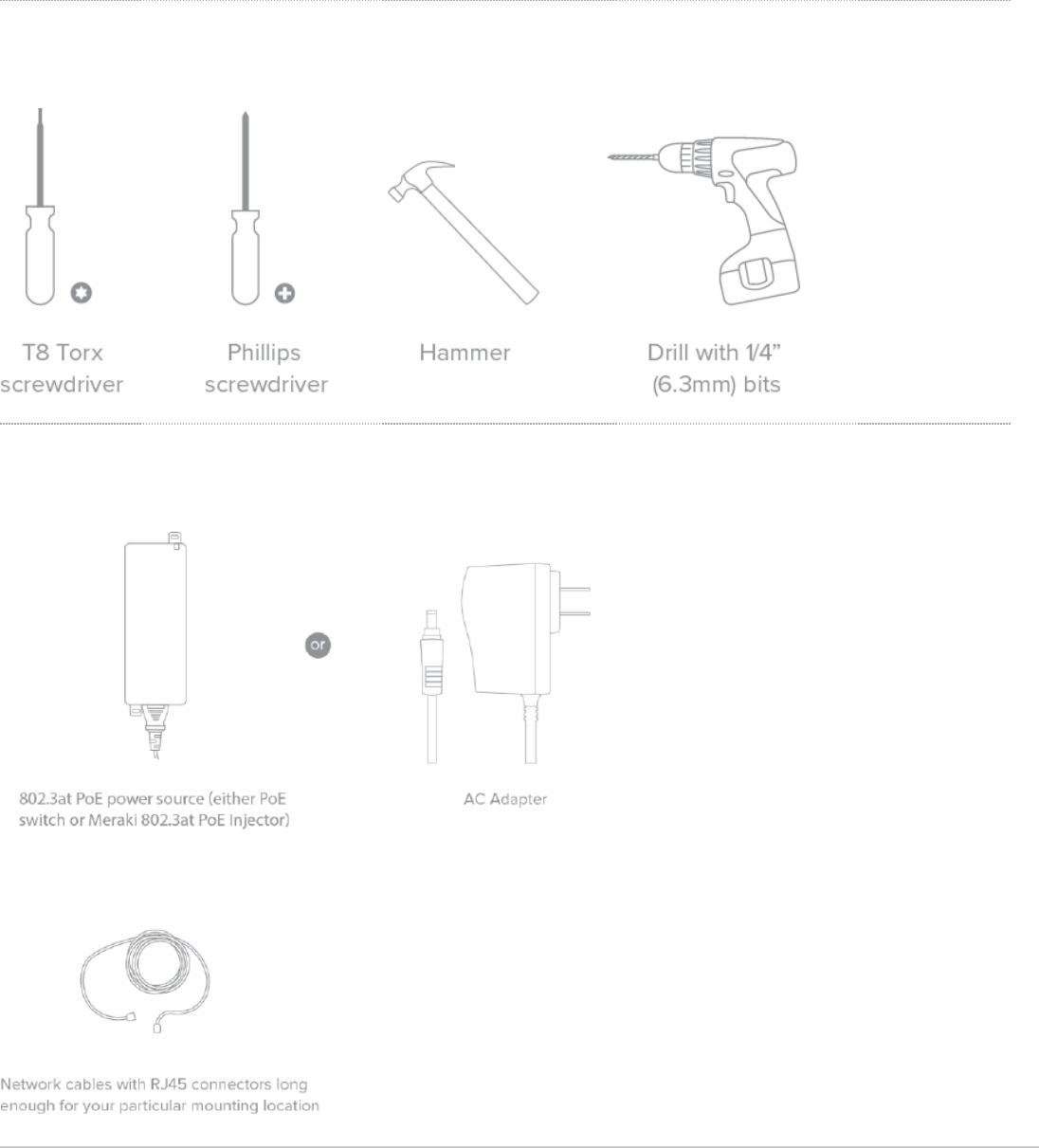
Collect Tools
You will need the following tools to perform an installation:
Collect Additional Hardware for Installation
You will need the following hardware to perform an installation:
8

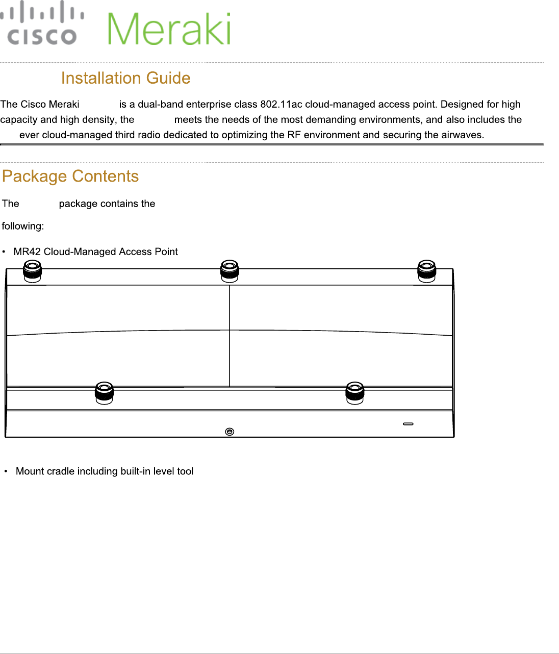
Installation Instructions
Choose Your Mounting Location
A good mounting location is important to getting the best performance out of your MR42E access point. Keep
the following in mind:
1. The device should have unobstructed line of sight to most coverage areas. For example, if installing in an office
filled with workspaces divided by mid-height cubicle walls, installing on the ceiling or high on a wall would be ideal.
2. Power over Ethernet supports a maximum cable length of 300 ft (100 m).
3. If being used in a mesh deployment, the MR42E should have line of sight to at least two other Meraki devices. A
Cisco Partner can help ensure that your AP placement is ideal.
Install the MR42E
For most mounting scenarios, the MR42E mount cradle provides a quick, simple, and flexible means of mounting
your device. The installation should be done in two steps. First, install the mount cradle to your selected location.
Then, attach the MR42E to the mount cradle.
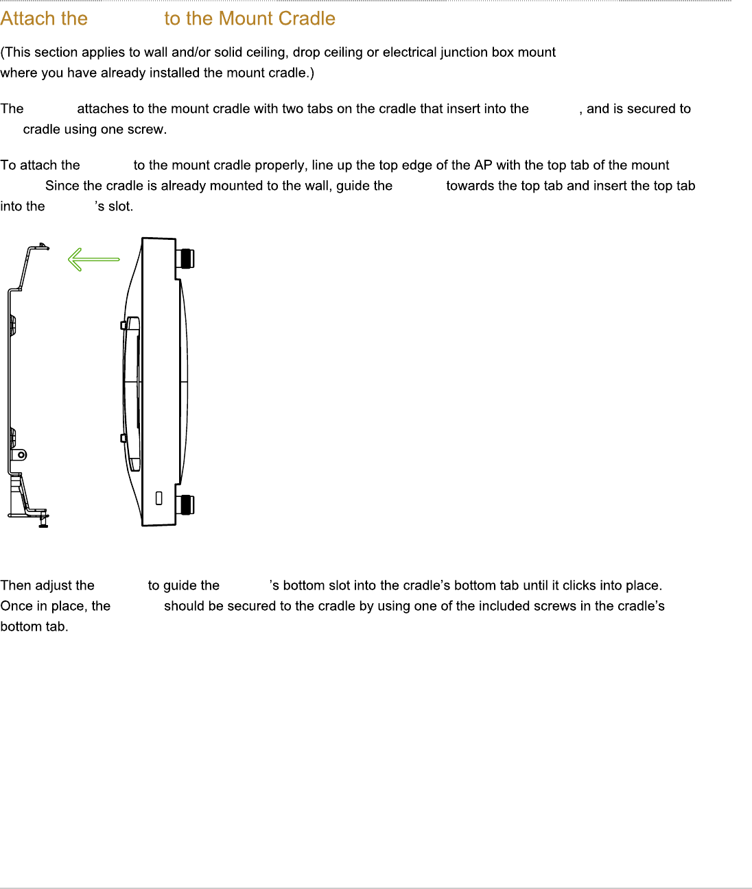
Attach the mount cradle
The MR42E mount cradle can be used to install your access point in a wide range of scenarios: wall or solid ceiling,
below a drop ceiling, on various electrical junction boxes.
The mount cradle contains a variety of hole patterns that are customized for each installation scenario. The mounting
template (included inbox with mount cradle) should be used to drill holes for wall mounts and also to identify the correct
hole patterns in the mount cradle that should be used for each type of mount. The included mount cradle
template shows the hole patterns that should be used for each type of mount.
Wall or Solid Ceiling Mount Using mount cradle
Using included wall anchors and screws, attach the mount cradle to your mounting wall or ceiling. It is
recommended that the MR42E be mounted to a wall or solid ceiling using the mount cradle for physical
security reasons.
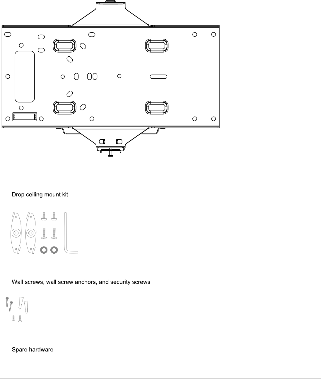
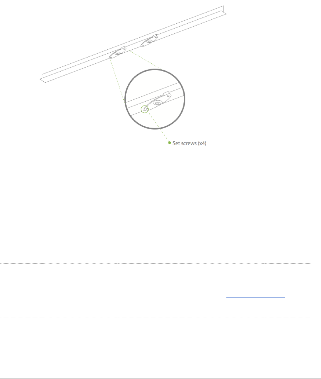
Drop ceiling mount using mount cradle
To mount your MR42E on a drop ceiling T-rail, use the included drop ceiling mounting accessory kit. The
accessory kit can be used to mount to most 9/16”, 15/16” or 1 ½” T-rails. The kit contains:
• Drop ceiling mounting clips with set screws
9
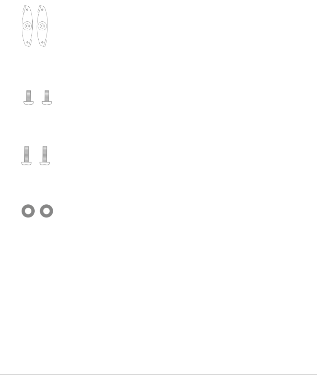
• 6-32x4 mm screws
• 6-32x7 mm screws only used for recessed rail mount (uncommon)
• 2 rubber spacers
1. Attach the T-rail clips to the T-rail by rotating them and snapping them into place as shown. The black foam
pads should be compressed slightly after installation.
10
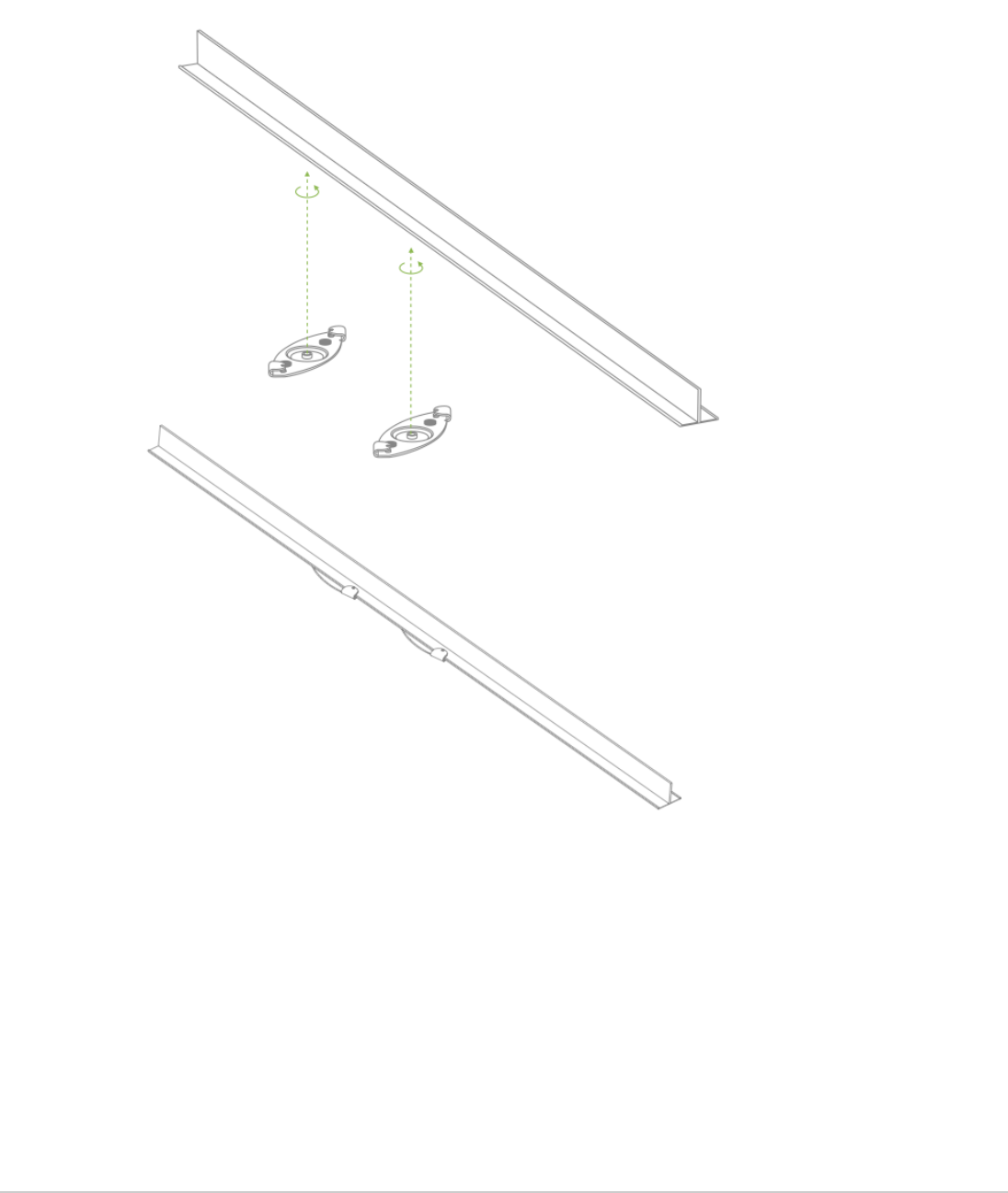
2. Using the dashed lines on the mount cradle template as a guide, set the proper spacing of the T-rail clips on
the T-rail.
3. Tighten the set screws on the T-rail clips to secure the clips using a 5/64”(2 mm) hex key.
11
4. Attach the mount cradle to the T-rail clips using the mount cradle holes (marked with a “T“).
Tip: Pre-assemble rubber spacers and screws to the mount cradle. The mount cradle can then be held with one
hand while the other hand holds a screwdriver. If mounting your MR42E to a dropped ceiling, skip to the "Power
the MR42E" section.
Electrical Junction Box Mount Using mount cradle
The MR42E can be mounted to a 4” square cable junction box, a 3.5 or 4” round cable junction box, or various
U.S. and European outlet boxes (mounting screws are not included).
Using appropriate mounting hardware for your specific type of junction box, attach the mount cradle to the
junction box.
Power the MR42E
If mounting to an electrical junction box, feed the Ethernet cable through the cable access hole in the mount cradle. If
mounting to a wall or ceiling, the Ethernet cable will feed from behind the MR42E. The "Power Source Options" section
of this document lists the different powering options and their unique characteristics.
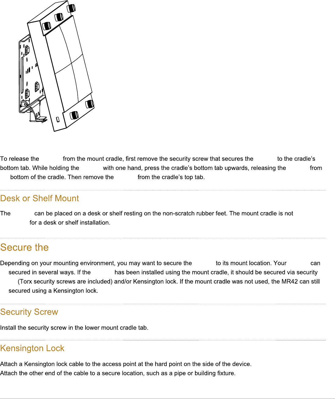
Mount the MR42E
12
MR42E
MR42E MR42E
C74
MR42E
2A03;4 MR42E
MR42E
MR42E MR42E
MR42E
13
Security screw shown
for orientation
MR42E MR42E
MR42E MR42E
C74 MR42E
MR42E
=424BB0AH
MR42E
MR42E MR42E
14 MR42E
B2A4F
14
14

Verify Device Functionality and Test Network Coverage
1. Check LEDs
a. The Power LED should be solid green (or blue, if clients are connected). If it is flashing blue, the firmware is
automatically upgrading and the LED should turn green when the upgrade is completed (normally within a
few minutes). See the " LED Indicators" section for more details. .
b. Note: Your MR42E must have an active route to the Internet to check and upgrade its firmware.
2. Verify access point connectivity
a. Use any 802.11 client device to connect to the MR42E and verify proper connectivity using the client’s web
browser.
3. Check network coverage
4. Confirm that you have good signal strength throughout your coverage area. You can use the signal strength meter
on a laptop, smart phone, or other wireless device.
Troubleshooting
Reference the MR Product Page for additional information and troubleshooting tips.
15