Cisco Systems 60064010 802.11 a/b/g/n/ac Wireless Access Point User Manual UDX 60064010 Installation Guide

Cisco Systems 802.11 a/b/g/n/ac Wireless Access Point UDX 60064010 Installation Guide

Contents

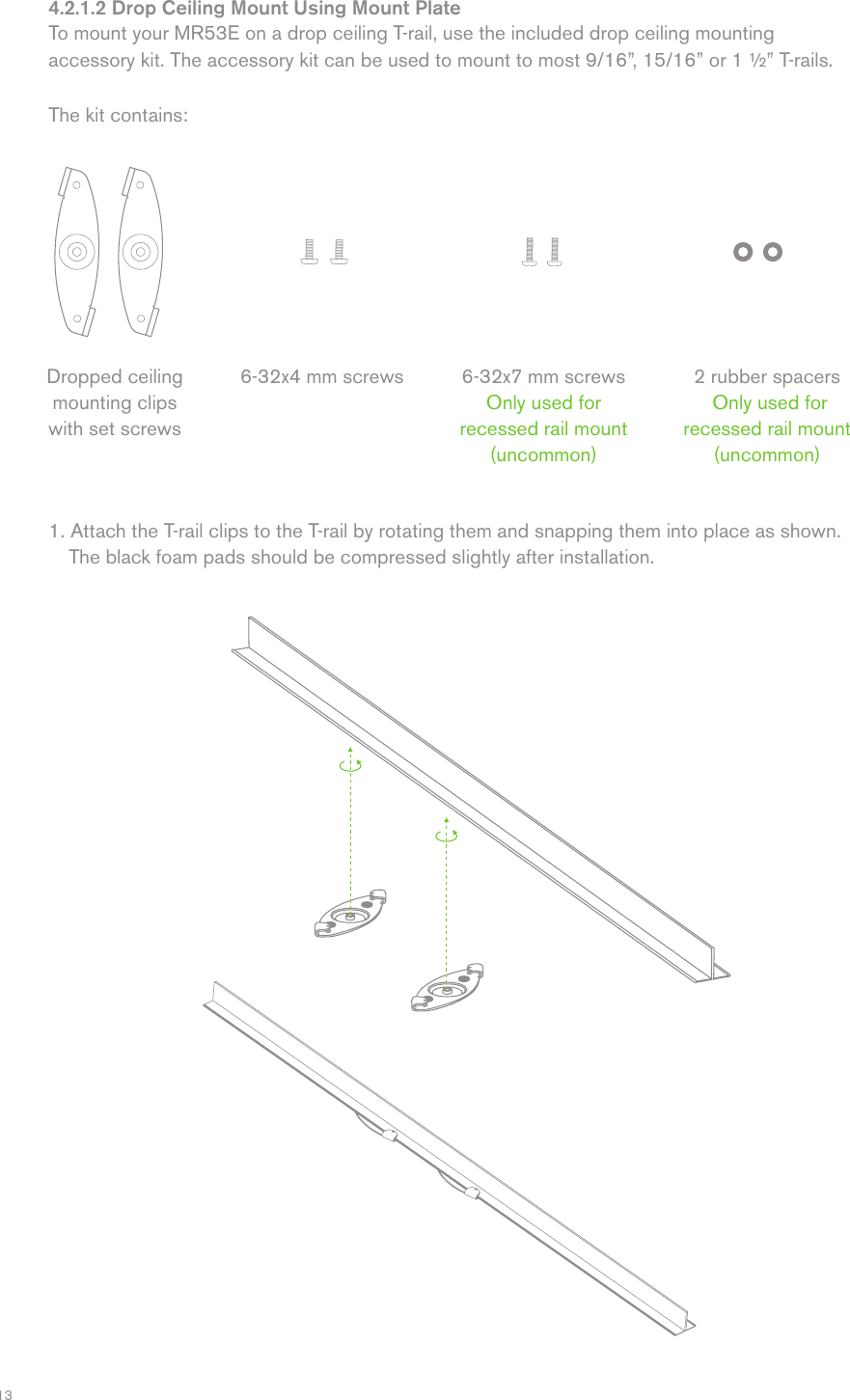
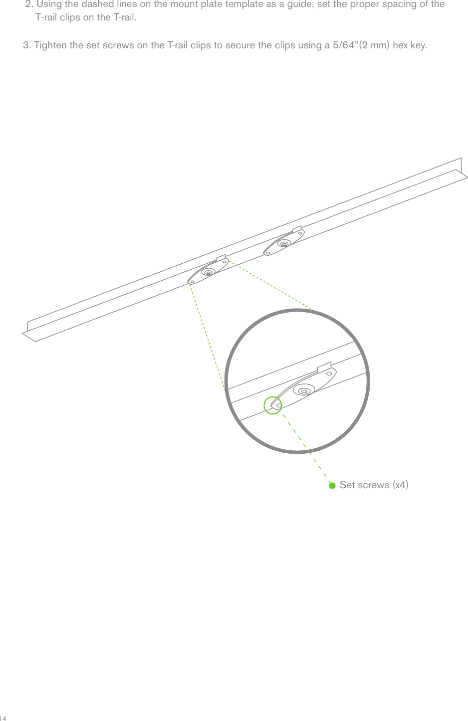
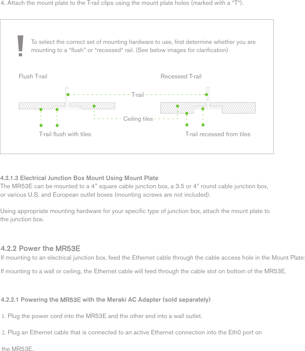
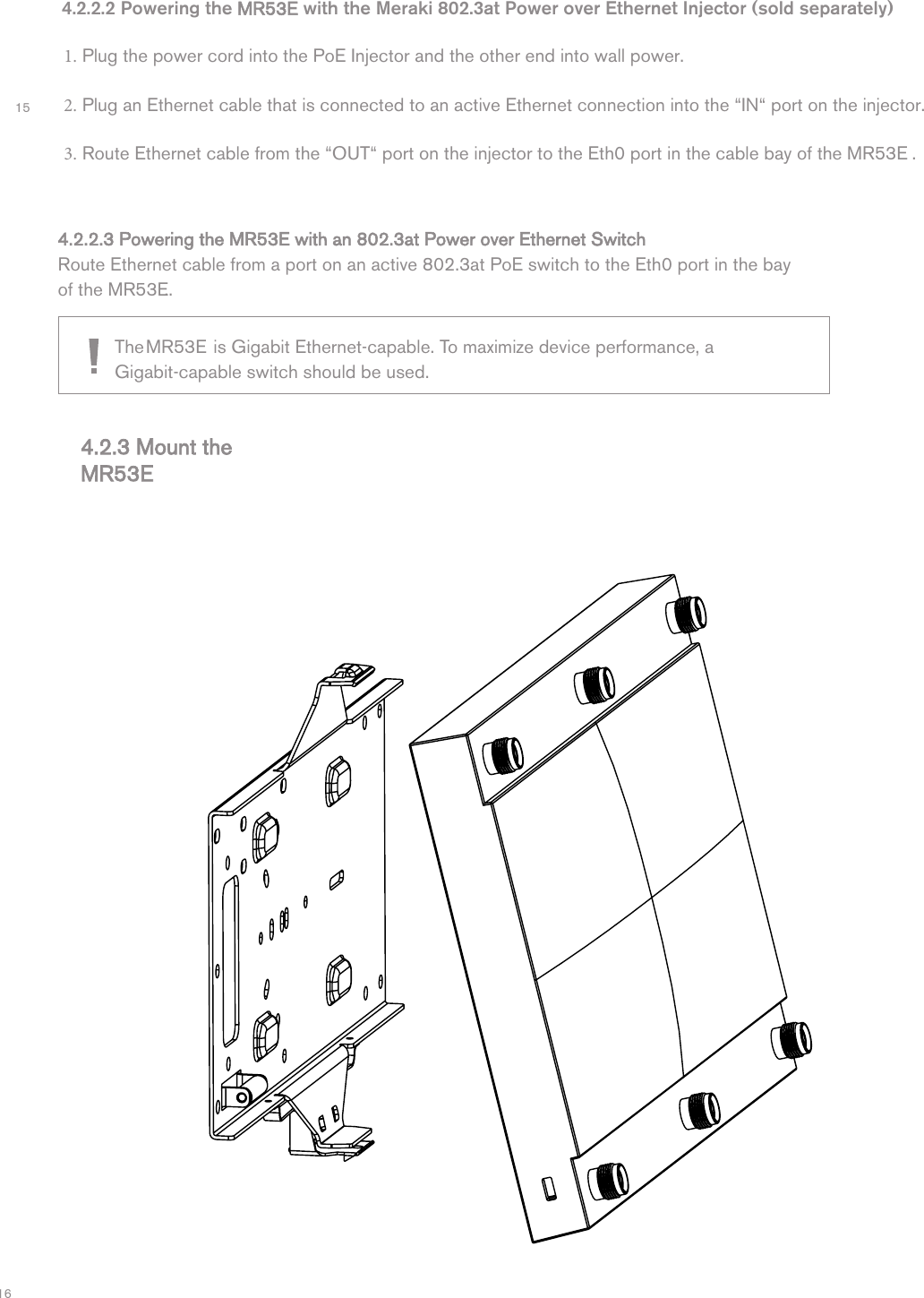
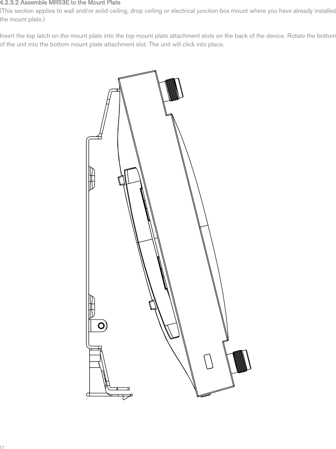
UDX-60064010_Installation Guide

Meraki MR53EHardware Installation Guide
TrademarksMeraki, Meraki MR53E, Meraki Cloud Controller, and Meraki Mesh are trademarks of Cisco Systems, Inc. Other brand and product names are registered trademarks or trademarks of their respective holders.Statement of ConditionsIn the interest of improving internal design, operational function, and/or reliability, Cisco Systems reserves the right to make changes to the products described in this document without notice. Cisco Systems does not assume any liability that may  occur due to the use or application of the product(s) or circult layout(s) described herein.WarrantyMeraki, Inc. provides a lifetime warranty on this product. Warranty details may be found at www.meraki.com/legal.
34 Table of Contents1   Scope of Document and Related Publications 2   MR53E Overview  5 5 57 77 7 2.1 Package Contents 2.2 Understanding the MR53E  2.3 Antenna Information2.4 Security Features 2.5 Ethernet Ports 2.6 Power Source Options 2.7 Factory Reset Button  7 3   Pre-Install Preparation 8 88 83.1 Configure Your Network in Dashboard 3.2 Check and Upgrade Firmware 3.3 Check and Configure Firewall Settings 3.4 Assigning IP Addresses to MR53Es 93.4.1 Dynamic Assignment 93.4.2 Static Assignment 9 3.4.3 Static IP Assignment via DHCP Reservations 93.5 Collect Tools 10 3.6 Collect Additional Hardware for Installation 104   Installation Instructions 11 11 114.1 Choose Your Mounting Location 4.2 Install the MR53E 4.2.1 Attach the Mount Plate 11 4.2.1.1 Wall or Solid Ceiling Mount Using Mount Plate 13 4.2.1.2 Drop Ceiling Mount Using Mount Plate 14 4.2.1.3 Electrical Junction Box Mount Using Mount Plate 18 4.2.2 Power the MR53E  202121 4.2.2.1 Powering the MR53E with Meraki AC Adapter 4.2.2.2 Powering the MR53E with Meraki 802.3af Power over Ethernet Injector 4.2.2.3 Powering the MR53E with an 802.3af Power over Ethernet Switch 22  4.2.3 Mount the MR53E 22 224.2.3.1 Assemble Security Hasp to the MR53E4.2.3.2 Assemble MR53E to the Mount plate4.2.3.3 Desk or Shelf Mount 23 25  4.3 Secure the MR53E 264.3.1 Security Screw  264.3.2 Kensington Lock  264.4 Verify Device Functionality and Test Network Coverage  27 5   Troubleshooting 27
41   Scope of Document and Related PublicationsThe MR53E Hardware Installation Guide describes the installation procedure for the MR53E indoor access point.   Additional reference documents are available online at www.meraki.com/library/product.
52    MR53E OverviewThe  Meraki MR53E  is  an  enterprise-class,  dual-concurrent  4x4  MIMO  802.11ac  indoor  access  point  designed  for high-density  deployments  in  offices,  schools,  hospitals  and  hotels.  When  connected  to  the  Meraki Cloud Controller, the MR53 enables the creation of ultra-high speed, reliable indoor wireless networks quickly, easily, and cost-effectively.2.1  Package ContentsThe MR53E package contains the following: 2.2  Understanding the MR53EOperation Temperature:32 °  F to 104 ° F (0 ° C to 40 °  C)Your Meraki MR53E has the following features: Kensington lock hard point Mounting TemplateMR53E access point Mounting plateDrop ceiling mounting kit Wall screws  Security screws
6Your MR53E mount plate has the following features: Access point mounting posts (2x)Mount plate attachment slots (2x)Cable access bayDesk mount feet (4x)MR53E cable access bayFactory Reset ButtonEthernet 0 port (10/100/1000)Power supplied by PoE: 37-57 Vdc, 0.6AAC Adapter plug (sold separately) Power supplied by adapter: 12Vdc, 2.5AVarious mounting holes
7The MR53E features multiple options for physically securing the access point after installation:1. Security screw – The accessory kit includes screws that can be used to secure the access point tothe mount plate. Engaging the security screw prevents accidental dislodging and theft.2. Kensington lock – The access point contains a hard point that allows it to be secured to any nearbypermanent structure using a standard Kensington lock.MR532.5  Ethernet PortsThe MR53E features a Gigabit Ethernet RJ45 port that accepts 802.3at power (labeled  “PoE”).  This port should be used for uplink to your WAN connection.   2.6  Power Source OptionsThe MR53E access point can be powered using either the Meraki AC Adapter or 802.3at PoE Injector (both sold separately) or a third-party 802.3at PoE switch.2.7  Factory Reset ButtonIf the button is pressed and held for at least five seconds and then released, the MR53E will reboot and be restored to its original factory settings by deleting all configuration information stored on the unit.The M53E will have five antenna options and the one version, dipole, will be the only variant that will not have a “self-identification” capability.The four antenna variants that are self-identification type are as follows:•Can Omini•Down-tilt Omni•Narrow Patch (NP)•Wide Patch (WP)2.3 Antenna Information2.4 Security Features
83   Pre-Install PreparationYou should complete the following steps before going on-site to perform an installation. 3.1  Configure Your Network in DashboardThe following is a brief overview only of the steps required to add an MR53E to your network. For detailed instructions about creating, configuring and managing Meraki wireless networks, refer to the Meraki Cloud Controller Manual (meraki.com/library/product).1. Login to http://dashboard.meraki.com. If this is your first time, create a new account.2. Find the network to which you plan to add your APs or create a new network.3. Add your APs to your network. You will need your Meraki order number (found on your invoice if youordered directly from Meraki) or the serial number of each AP, which looks like Qxxx-xxxx-xxxx, and isfound on the bottom of the unit.  You will also need your Enterprise Cloud Controller license key, which youshould have received via email from shipping@meraki.com.4. Go to the map / floor plan view and place each AP on the map by clicking and dragging it to the locationwhere you plan to mount it.3.2  Check and Upgrade FirmwareTo ensure your MR53E performs optimally immediately following installation, Meraki recommends that you facilitate a firmware upgrade prior to mounting your MR53E. Attach your MR53E to power and a wired Internet connection. See p. 19 of this Hardware Installation Guide for details. The MR53E will turn on and the Power LED will glow solid orange. If the unit does not require a firmwareupgrade, the Power LED will turn white within thirty seconds. * If the unit requires an upgrade, the Power LED will begin blinking orange until the upgrade is complete,at which point the Power LED will turn solid white. You should allow about an hour for the firmwareupgrade to complete, depending on the speed of your internet connection.3.3  Check and Configure Firewall SettingsIf a firewall is in place, it must allow outgoing connections on particular ports to particular IP addresses.  The most current list of outbound ports and IP addresses can be found here:http://tinyurl.com/y79une3
93.4 Assigning IP Addresses to MR53EsAll gateway MR53Es (MR53Es with Ethernet connections to the LAN) must be assigned routable IP addresses.  These IP addresses can be dynamically assigned via DHCP or statically assigned.3.4.1 Dynamic AssignmentWhen using DHCP, the DHCP server should be configured to assign a static IP address for each MAC address belonging to a Meraki AP.  Other features of the wireless network such as 802.1x authentication, may rely on the property that the APs have static IP addresses.3.4.2 Static AssignmentStatic IPs are assigned using the local web server on each AP.  The following procedure describes how to set the static IP: Using a client machine (e.g. a laptop), connect to the AP either wirelessly (by associating to any SSIDbroadcast by the AP) or over a wired connection.If using a wired connection, connect the client machine to the MR53E either through a PoE switch or a Meraki PoE Injector.  If using a PoE switch, plug an Ethernet cable into the MR53E Ethernet jack, and the other end into a PoE switch.  Then connect the client machine over Ethernet cable to the PoE switch.  If using a Meraki PoE Injector, connect the MR53E to the “PoE” port of the Injector, and the client machine to the “LAN” port. Using a web browser on the client machine, access the AP’s built-in web server by browsing tohttp://my.meraki.com.  Alternatively, browse to http://10.128.128.128. Click on the “Static IP Configuration” tab.  Log in.  The default user name is “admin”.  The default password isthe AP’s serial number, with hyphens included Configure the static IP address, net mask, gateway IP address and DNS servers that this AP will use on itswired connection. If necessary, reconnect the AP to the LAN. 3.4.3 Static IP via DHCP ReservationsInstead of associating to each Meraki AP individually to configure static IP addresses, an administrator can assign  static IP addresses on the upstream DHCP server.  Through “DHCP reservations”, IP addresses are “reserved” for the MAC addresses of the Meraki APs.  Please consult the documentation for the DHCP server to configure DHCP reservations.
10Phillips screwdriverHammer Drill with 1/4” (6.3mm) bits3.6  Collect Additional Hardware for Installation802.3at PoE power source (either PoE  switch or Meraki 802.3at PoE Injector)Network cables with RJ45 connectors long enough for your particular mounting location3.5  Collect Tools         You will need the following tools to perform an installation:AC Adapteror
114   Installation Instructions4.1  Choose Your Mounting LocationA good mounting location is important to getting the best performance out of your MR53E access point.  Keep the following in mind: The device should have unobstructed line of sight to most coverage areas. For example, if installingin an office filled with workspaces divided by mid-height cubicle walls, installing on the ceiling or highon a wall would be ideal. Power over Ethernet supports a maximum cable length of 300 ft (100 m). If being used in a mesh deployment, the MR53E should have line of sight to at least two other devices. For more detailed instructions regarding access point location selection, reference the Meraki   Design Guide (meraki.com/library/product). 4.2  Install the MR53EFor most mounting scenarios, the MR53E mount plate provides a quick, simple, and flexible means of mounting your device. The installation should be done in two steps. First, install the mount plate to your selected location. Then, attach the MR53E to the mount plate. 4.2.1 Attach the Mount PlateThe MR53E mount plate can be used to install your access point in a wide range of scenarios: wall or solid ceiling, below a drop ceiling, on various electrical junction boxes, or above a drop ceiling (in the plenum).  The mount plate contains a variety of hole patterns that are customized for each installation scenario. The  mounting template (included inbox with mount plate) should be used to drill holes for wall mounts and also to identify the correct hole patterns in the mount plate that should be used for each type of mount.  The following images also show the hole patterns that should be used for each type of mount:
124.2.1.1 Wall or Solid Ceiling Mount Using Mount PlateUsing included screws, attach the mount plate to your mounting wall or ceiling.It is recommended that the MR53E be mounted to a wall or solid ceiling using  the mount plate for physical security reasons.If mounting your MR53E to a wall, skip to “Power the MR53E" on P. 20
131. Attach the T-rail clips to the T-rail by rotating them and snapping them into place as shown.The black foam pads should be compressed slightly after installation.Dropped ceiling mounting clipswith set screws6-32x4 mm screws 6-32x7 mm screwsOnly used forrecessed rail mount (uncommon)2 rubber spacers Only used for recessed rail mount (uncommon)4.2.1.2 Drop Ceiling Mount Using Mount PlateTo mount your MR53E on a drop ceiling T-rail, use the included drop ceiling mounting accessory kit. The accessory kit can be used to mount to most 9/16”, 15/16” or 1 ½” T-rails.  The kit contains:
143. Tighten the set screws on the T-rail clips to secure the clips using a 5/64”(2 mm) hex key.2. Using the dashed lines on the mount plate template as a guide, set the proper spacing of theT-rail clips on the T-rail.Set screws (x4)
4. Attach the mount plate to the T-rail clips using the mount plate holes (marked with a “T“).To select the correct set of mounting hardware to use, first determine whether you are mounting to a “flush” or “recessed“ rail. (See below images for clarification)Flush T-rail Recessed T-railT-rail flush with tiles T-rail recessed from tilesCeiling tilesT-rail4.2.1.3 Electrical Junction Box Mount Using Mount PlateThe MR53E can be mounted to a 4” square cable junction box, a 3.5 or 4” round cable junction box, or various U.S. and European outlet boxes (mounting screws are not included). Using appropriate mounting hardware for your specific type of junction box, attach the mount plate to the junction box.4.2.2 Power the MR53E If mounting to an electrical junction box, feed the Ethernet cable through the cable access hole in the Mount Plate:If mounting to a wall or ceiling, the Ethernet cable will feed through the cable slot on bottom of the MR53E.4.2.2.1 Powering the MR53E with the Meraki AC Adapter (sold separately) Plug the power cord into the MR53E and the other end into a wall outlet. Plug an Ethernet cable that is connected to an active Ethernet connection into the Eth0 port on the MR53E.
16154.2.2.2 Powering the MR53E with the Meraki 802.3at Power over Ethernet Injector (sold separately) Plug the power cord into the PoE Injector and the other end into wall power. Plug an Ethernet cable that is connected to an active Ethernet connection into the “IN“ port on the injector.  Route Ethernet cable from the “OUT“ port on the injector to the Eth0 port in the cable bay of the MR53E . 4.2.3 Mount the MR53E4.2.2.3 Powering the MR53E with an 802.3at Power over Ethernet Switch Route Ethernet cable from a port on an active 802.3at PoE switch to the Eth0 port in the bay of the MR53E..The MR53E   is Gigabit Ethernet-capable. To maximize device performance, a Gigabit-capable switch should be used.
174.2.3.2 Assemble  MR53E to the Mount Plate(This section applies to wall and/or solid ceiling, drop ceiling or electrical junction box mount where you have already installed the mount plate.) Insert the top latch on the mount plate into the top mount plate attachment slots on the back of the device. Rotate the bottom of the unit into the bottom mount plate attachment slot. The unit will click into place.
184.2.3.3 Desk or Shelf MountThe MR53E can be placed on a desk or shelf resting on the non-scratch rubber feet. The mount plate is not necessary for a desk or shelf mounting.4.3  Secure the MR53E Depending on your mounting environment, you may want to secure the MR53E to its mount location. YourMR53E can be secured in several ways. If the MR53 has been installed using the mount plate, it can be secured via security screw (Torx and phillips head security screws are included; choose one), and/or Kensington lock. If the mount  plate was not used, the MR53E can still be secured using a Kensington lock. 4.3.1 Security Screw Install the security screw in the lower mount plate tab. 4.3.2 Kensington LockAttach a Kensington lock cable to the access point at the hard point on the side of the device. Attach the other end of the cable to a secure location, such as a pipe or building fixture.
194.4  Verify Device Functionality and Test Network Coverage Check LEDsThe  LED should be solid white. If it is flashing orange, the firmware is automatically upgrading and theLED should turn green when the upgrade is completed (normally in under thirty minutes).Note: Your MR53E must have an active route to the Internet to check and upgrade its firmware. Verify access point connectivityUse any 802.11 client device to connect to the MR53E and verify proper connectivity using the client’s web browser. Check network coverageConfirm that you have good signal strength throughout your coverage area. You can use the signal strength meteron a laptop, smart phone, or other wireless device. 5  TroubleshootingReference the Meraki knowledge base at http://meraki.com/support/knowledge_base for additional information and troubleshooting tips.6  RegulatoryFCC Compliance StatementThis device complies with part 15 of the FCC rules. Operation is subject to the following two conditions: (1) This de-vice   may not cause harmful interference, and (2) this device must accept any interference received, including interference tial that may cause undesired operation.FCC Interference StatementThis equipment has been tested and found to comply with the limits for a Class B digital device, pursuant to part 15 of the FCC Rules. These limits are designed to provide reasonable protection against harmful interference in a residen-  installation. This equipment generates, uses and can radiate radio frequency energy and, if not installed and used in ac cordance with the instructions, may cause harmful interference to radio communications. However, there is noguarantee that interference will not occur in a particular installation. If this equipment does cause harmful interference  to radio or television reception, which can be determined by turning the equipment off and on, the user is encouraged  to correct the interference by one of the following measures:• Reorient or relocate the receiving antenna.• Increase the separation between the equipment and receiver.• Connect the equipment into an outlet on a circuit different from which the receiver is connected.• Consult the dealer or an experienced radio/TV technician for  help.FCC CautionAny changes or modifications no expressly approved by Meraki could void the user’s authority to operate this equipment. This Transmitter must not be co-located or operation in conjunction with any other antenna or transmitter.FCC Radiation Exposure StatementThis equipment complies with FCC radiation exposure limits set forth for an uncontrolled environment. This equipment should be installed and operated with minimum distance 30 cm between the radiator and your body. This transmitter  must not be co-located or operating in conjunction with any other antenna or transmitter.IEEE 802.11b or 802.11g operation of this product in the USA is firmware-limited to channels 1 through 11.
If the device is going to be operated in the 5.15 - 5.25 frequency range, then it is restricted to indoor environment only. This device meets all other requirements specified in Part 15E, Section 15.407 of the FCC Rules.Industry Canada StatementThis device complies with RSS-247 of the Industry Canada Rules. Operation is subject to the following two conditions: (1) This device may not cause harmful interference, and (2) this device must accept any interference received, includinginterference that may cause undesired operation.Ce dispositif est conforme à la norme CNR-247 d’Industrie Canada applicable aux appareils radio exempts de licence. Son fonctionnement est sujet aux deux conditions suivantes: (1) le dispositif ne doit pas produire de brouillagepréjudiciable, et (2) ce dispositif doit accepter tout brouillage reçu, y compris un brouillage susceptible de provoquer un fonctionnement indésirable. Industry Canada Caution(i) the device for operation in the band 5150-5250 MHz is only for indoor use to reduce the potential for harmfulinterference to co-channel mobile satellite systems;(ii) high-power radars are allocated as primary users (i.e. priority users) of the bands 5250-5350 MHz and 5650-5850 MHzand that these radars could cause interference and/or damage to LE-LAN devices.Avertissement:(i) les dispositifs fonctionnant dans la bande 5 150-5 250 MHz sont réservés uniquement pour une utilisation à l’intérieurafin de réduire les risques de brouillage préjudiciable aux systèmes de satellites mobiles utilisant les mêmes canaux;(ii) De plus, les utilisateurs devraient aussi être avisés que les utilisateurs de radars de haute puissance sont désignésutilisateurs principaux (c.-à-d., qu’ils ont la priorité) pour les bandes 5 250-5 350 MHz et 5 650-5 850 MHz et que ces radars pourraient causer du brouillage et/ou des dommages aux dispositifs LAN-EL.Industry Canada Radiation Exposure StatementThis equipment complies with IC radiation exposure limits set forth for an uncontrolled environment. This equipment should be installed and operated with minimum distance 38 cm between the radiator & your body.Déclaration d’exposition aux radiationsCet équipement est conforme aux limites d’exposition aux rayonnements IC établies pour un environnement non con trôlé. Cet équipement doit être installé et utilisé avec un minimum de 38 cm de distance entre la source de rayonnement  et votre corps.Copyright © 2016 Cisco Systems, Inc. All rights reserved. Trademarks Cisco Systems® is a registered trademark of Cisco Systems, Inc.  24www.ciscosystems.com Cisco Systems, Inc.170 West Tasman Drive San Jose, CA 95134 USA20

Navigation menu