Cisco Systems 60066010 802.11 a/b/g/n/ac Wireless Access Point User Manual UDX 60066010 Installation Guide
Cisco Systems 802.11 a/b/g/n/ac Wireless Access Point UDX 60066010 Installation Guide
UDX-60066010_Installation Guide
Package Contents
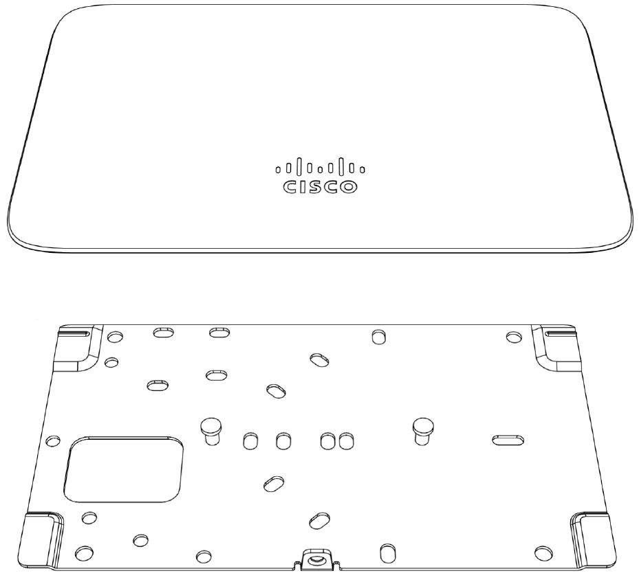
The Cisco Meraki MR20-HW package contains the following:
• MR20-HW Cloud-Managed Access Point
• Mount plate
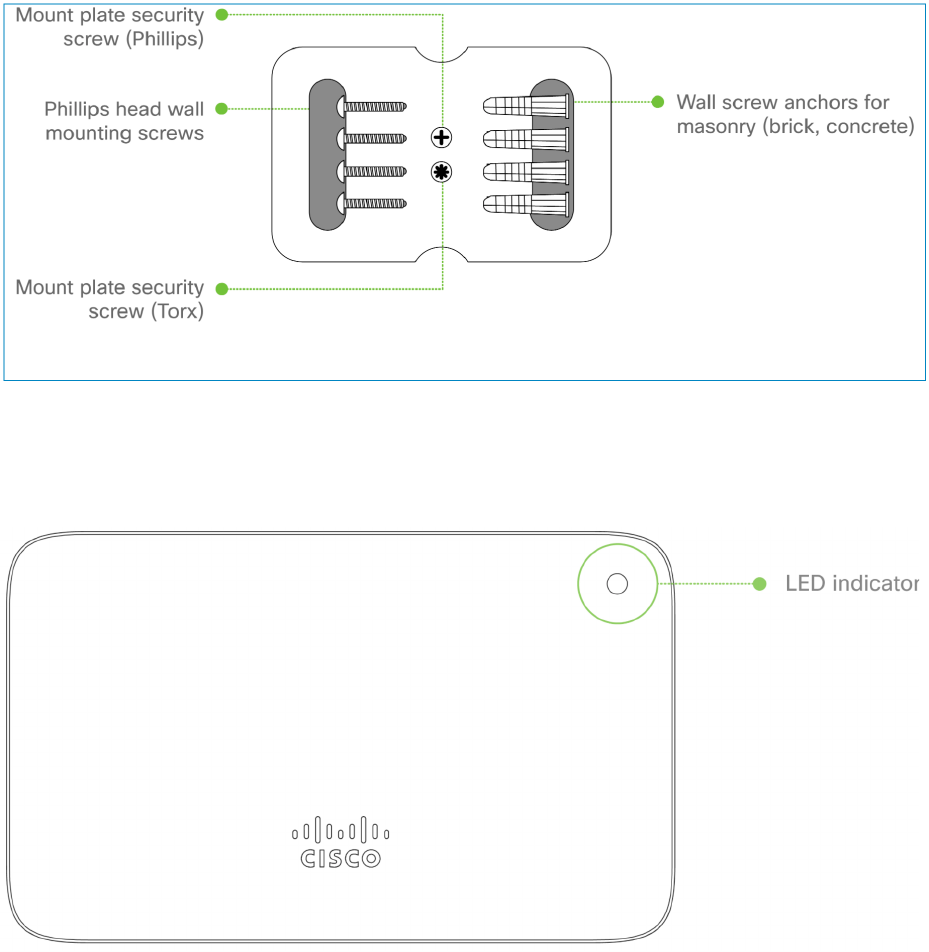
• Mount Kit
o Wall screws, wall screw anchors, and security screws
Understanding the MR20-HW
Your Meraki MR20-HW has the following features:
The mount plate has the following features:
Security Features
The MR20-HW features multiple options for physically securing the access point after
installation:
1. Security screw – The accessory kit includes screws that can be used to secure the
access point to the mount cradle. Engaging the security screw prevents accidental
dislodging and theft.
Ethernet Ports

The MR20-HW features a Gigabit Ethernet RJ45 port that accepts 802.3at and 802.3af
power (labeled “Eth0, PoE”). This port should be used for uplink to your WAN connection.
Power Source Options
The MR20-HW access point can be powered using either the Meraki AC Adapter, PoE
Injector (both sold separately), or a third-party PoE switch.
Factory Reset Button
If the button is pressed and held for at least five seconds and then released, the MR20-
HW will reboot and be restored to its original factory settings by deleting all configuration
information stored on the unit.
LED Indicators and Run Dark Mode
Your MR20-HW is equipped with a multi-color LED light on the front of the unit to convey
information about system functionality and performance:
• Orange - AP is booting (permanent Orange suggests hardware issue)
• Rainbow - AP is initializing/scanning
• Blinking Blue - AP is upgrading
• Green - AP in Gateway mode with no clients
• Blue - AP in Gateway mode with clients
• Blinking Orange - AP can't find uplink
The MR20-HW may be operated in “Run Dark” mode for additional security and to
reduce the visibility of the access point. In this mode, the LED will not be illuminated. This
mode may be enabled through Meraki dashboard.
Pre-Install Preparation
You should complete the following steps before going on-site to perform an installation.
Configure Your Network in Dashboard
The following is a brief overview only of the steps required to add an MR20-HW to your
network. For detailed instructions about creating, configuring and managing Meraki
wireless networks, refer to the online documentation (documentation.meraki.com).
1. Login to http://dashboard.meraki.com. If this is your first time, create a new
account.
2. Find the network to which you plan to add your APs or create a new network.
3. Add your APs to your network. You will need your Meraki order number (found on
your invoice) or the serial number of each AP, which looks like Qxxx-xxxx-xxxx,
and is found on the bottom of the unit. You will also need your Enterprise license
key, which you should have received via email.
4. Go to the map / floor plan view and place each AP on the map by clicking and
dragging it to the location where you plan to mount it.

Check and Upgrade Firmware
To ensure your MR20-HW performs optimally immediately following installation, it is
recommended that you facilitate a firmware upgrade prior to mounting your MR20-HW.
1. Attach your MR20-HW to power and a wired Internet connection. See the "Power
the MR20-HW" section for details.
2. The MR20-HW will turn on and the LED will glow solid orange. If the unit does not
require a firmware upgrade, the LED will turn either green (no clients associated)
or blue (clients associated) within thirty seconds.
* If the unit requires an upgrade, the LED will begin blinking orange until the upgrade is
complete, at which point the LED will turn solid green or blue. You should allow at least a
few minutes for the firmware upgrade to complete, depending on the speed of your
internet connection.
Check and Configure Firewall Settings
If a firewall is in place, it must allow outgoing connections on particular ports to particular
IP addresses. The most current list of outbound ports and IP addresses for your particular
organization can be found here.
Assigning IP Addresses to MR20-HWs
All gateway MR20-HWs (MR20-HWs with Ethernet connections to the LAN) must be
assigned routable IP addresses. These IP addresses can be dynamically assigned via
DHCP or statically assigned.
Dynamic Assignment
When using DHCP, the DHCP server should be configured to assign a static IP address
for each MAC address belonging to a Meraki AP. Other features of the wireless network,
such as 802.1X authentication, may rely on the property that the APs have static IP
addresses.
Static Assignment
Static IPs are assigned using the local web server on each AP. The following procedure
describes how to set the static IP:
1. Using a client machine (e.g., a laptop), connect to the AP wirelessly (by associating
to any SSID broadcast by the AP) or over a wired connection.
2. If using a wired connection, connect the client machine to the MR20-HW either
through a PoE switch or a PoE Injector. If using a PoE switch, plug an Ethernet
cable into the MR20-HW’s Ethernet jack, and the other end into a PoE switch.
Then connect the client machine over Ethernet cable to the PoE switch. If using a
PoE Injector, connect the MR20-HW to the “PoE” port of the Injector, and the
client machine to the “LAN” port.
3. Using a web browser on the client machine, access the AP’s built-in web server by
browsing to http://my.meraki.com. Alternatively, browse to http://10.128.128.128.
4. Click on the “Uplink Configuration” tab. Log in. The default login is the serial
number (e.g. Qxxx-xxxx-xxxx), with no password (e.g., Q2DD-551C-ZYW3).
5. Configure the static IP address, net mask, gateway IP address and DNS servers
that this AP will use on its wired connection.
6. If necessary, reconnect the AP to the LAN.
Static IP via DHCP Reservations
Instead of associating to each Meraki AP individually to configure static IP addresses, an
administrator can assign static IP addresses on the upstream DHCP server. Through
“DHCP reservations,” IP addresses are “reserved” for the MAC addresses of the Meraki
APs. Please consult the documentation for the DHCP server to configure DHCP
reservations.
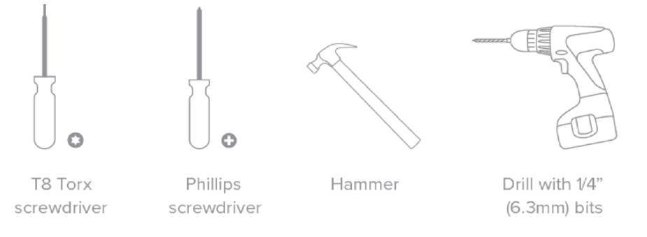
Collect Tools
You will need the following tools to perform an installation:
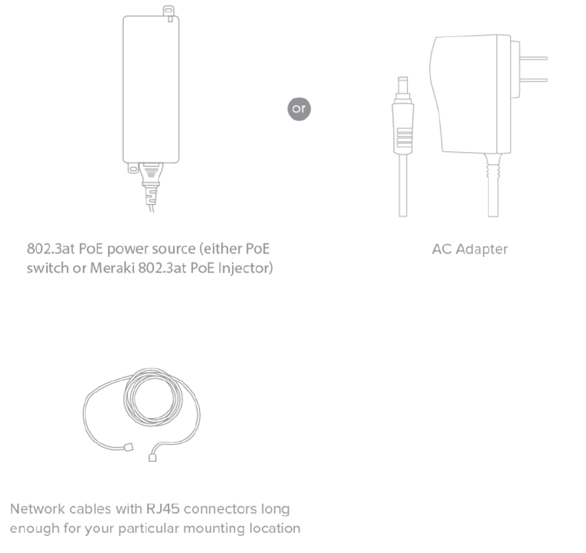
Collect Additional Hardware for Installation
You will need the following hardware to perform an installation:
Installation Instructions
Choose Your Mounting Location
A good mounting location is important to getting the best performance out of your
MR20-HW access point. Keep the following in mind:
1. The device should have unobstructed line of sight to most coverage areas. For
example, if installing in an office filled with workspaces divided by mid-height
cubicle walls, installing on the ceiling or high on a wall would be ideal.
2. Power over Ethernet supports a maximum cable length of 300 ft (100 m).
3. If being used in a mesh deployment, the MR20-HW should have line of sight to at
least two other Meraki devices. A Cisco Partner can help ensure that your AP
placement is ideal.
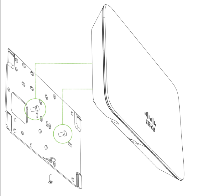
Mount the MR20-HW
Attach the MR20-HW to the Mount Cradle
The MR20-HW attaches to the mount cradle with two tabs on the cradle that insert into
the MR20-HW, and is secured to the cradle using one screw.
To attach the MR20-HW to the mount cradle properly, line up the top edge of the AP with
the top tab of the mount cradle. Since the cradle is already mounted to the wall, guide
the MR20-HW towards the top tab and insert the top tab into the MR20-HW’s slot.
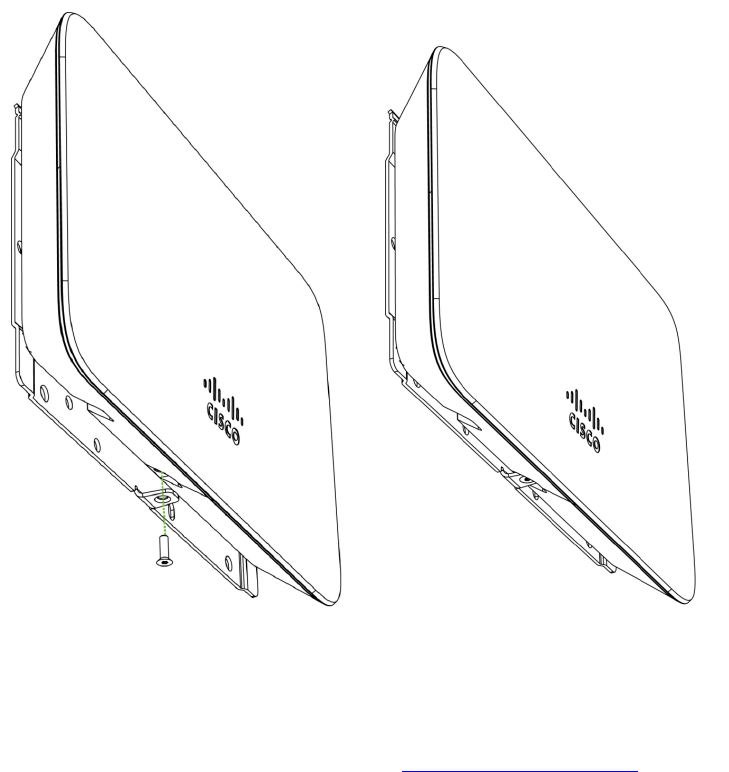
Then adjust the MR20-HW to guide the MR20-HW’s bottom slot into the cradle’s bottom
tab until it clicks into place. Once in place, the MR20-HW should be secured to the cradle
by using one of the included screws in the cradle’s bottom tab.
!
Power the MR20-HW
If mounting to an electrical junction box, feed the Ethernet cable through the cable
access hole in the mount cradle. If mounting to a wall or ceiling, the Ethernet cable will
feed from behind the MR20-HW. The "Power Source Options" section of this document
lists the different powering options and their unique characteristics.
Mount the MR20-HW
Attach the MR20-HW to the Mount Cradle
(This section applies to wall and/or solid ceiling, drop ceiling or electrical junction box
mount
where you have already installed the mount cradle.)
The MR20-HW attaches to the mount cradle with two tabs on the cradle that insert into
the MR20-HW, and is secured to the cradle using one screw.
To attach the MR20-HW to the mount cradle properly, line up the top edge of the AP with
the top tab of the mount cradle. Since the cradle is already mounted to the wall, guide
the MR20-HW towards the top tab and insert the top tab into the MR20-HW’s slot.

Then adjust the MR20-HW to guide the MR20-HW’s bottom slot into the cradle’s bottom
tab until it clicks into place. Once in place, the MR20-HW should be secured to the cradle
by using one of the included screws in the cradle’s bottom tab.
Error!%Reference%source%not%found.
Error!%Reference%source%not%found.
Error!%Reference%source%not%found.
To release the MR20-HW from the mount cradle, first remove the security screw that
secures the MR20-HW to the cradle’s bottom tab. While holding the MR20-HW with one
hand, press the cradle’s bottom tab upwards, releasing the MR20-HW from the bottom of
the cradle. Then remove the MR20-HW from the cradle’s top tab.
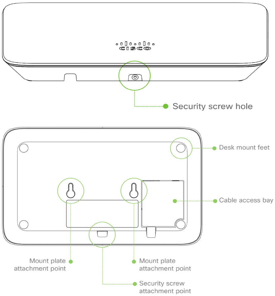
Desk or Shelf Mount
The MR20-HW can be placed on a desk or shelf resting on the non-scratch rubber feet.
The mount cradle is not necessary for a desk or shelf installation.
Secure the MR20-HW
Depending on your mounting environment, you may want to secure the MR20-HW to its
mount location. Your MR20-HW can be secured in several ways. If the MR20-HW has
been installed using the mount cradle, it should be secured via security screw (Torx
security screws are included) and/or Kensington lock. If the mount cradle was not used,
the MR20-HW can still be secured using a Kensington lock.
Power the MR20-HW
If mounting to an electrical junction box, feed the Ethernet cable through the cable
access hole in the mount cradle. If mounting to a wall or ceiling, the Ethernet cable will
feed from behind the MR20-HW. The "Power Source Options" section of this document
lists the different powering options and their unique characteristics.
Verify Device Functionality and Test Network Coverage
1. Check LEDs
a. The Power LED should be solid green (or blue, if clients are connected). If it
is flashing blue, the firmware is automatically upgrading and the LED
should turn green when the upgrade is completed (normally within a few
minutes). See the "LED Indicators" section for more details. .

b. Note: Your MR20-HW must have an active route to the Internet to check
and upgrade its firmware.
2. Verify access point connectivity
a. Use any 802.11 client device to connect to the MR20-HW and verify proper
connectivity using the client’s web browser.
3. Check network coverage
4. Confirm that you have good signal strength throughout your coverage area. You
can use the signal strength meter on a laptop, smart phone, or other wireless
device.
Troubleshooting
Reference the MR Product Page for additional information and troubleshooting tips.
Regulatory
This equipment is for indoor use only and the PoE device is considered unlikely to
connect to an Ethernet network with outside plant routing, including campus
environments.
FCC Compliance Statement
This device complies with part 15 of the FCC rules. Operation is subject to the following
two conditions: (1) This device may not cause harmful interference, and (2) this device
must accept any interference received, including interference that may cause undesired
operation.
FCC Interference Statement
This equipment has been tested and found to comply with the limits for a Class B digital
device, pursuant to part 15 of the FCC Rules. These limits are designed to provide
reasonable protection against harmful interference in a residential installation. This
equipment generates, uses and can radiate radio frequency energy and, if not installed
and used in accordance with the instructions, may cause harmful interference to radio
communications. However, there is no guarantee that interference will not occur in a
particular installation. If this equipment does cause harmful interference to radio or
television reception, which can be determined by turning the equipment off and on, the
user is encouraged to correct the interference by one of the following measures:
• Reorient or relocate the receiving antenna.
• Increase the separation between the equipment and receiver.
• Connect the equipment into an outlet on a circuit different from which the receiver is
connected.
• Consult the dealer or an experienced radio/TV technician for help.
FCC Caution
Any changes or modifications no expressly approved by Meraki could void the user’s
authority to operate this equipment. This Transmitter must not be co-located or operation
in conjunction with any other antenna or transmitter.
FCC Radiation Exposure Statement
This equipment complies with FCC radiation exposure limits set forth for an uncontrolled
environment. This equipment should be installed and operated with minimum distance
20 cm between the radiator and your body. This transmitter must not be co-located or
operating in conjunction with any other antenna or transmitter.
IEEE 802.11b or 802.11g operation of this product in the USA is firmware-limited to
channels 1 through 11.
If the device is going to be operated in the 5.15 - 5.25 frequency range, then it is
restricted to indoor environment only. This device meets all other requirements specified
in Part 15E, Section 15.407 of the FCC Rules.
Industry Canada Statement
This device complies with RSS-247 of the Industry Canada Rules. Operation is subject to
the following two conditions: (1) This device may not cause harmful interference, and (2)
this device must accept any interference received, including interference that may cause
undesired operation.
Ce dispositif est conforme à la norme CNR-247 d’Industrie Canada applicable aux
appareils radio exempts de licence. Son fonctionnement est sujet aux deux conditions
suivantes: (1) le dispositif ne doit pas produire de brouillage préjudiciable, et (2) ce
dispositif doit accepter tout brouillage reçu, y compris un brouillage susceptible de
provoquer un fonctionnement indésirable.
Industry Canada Caution
(i) the device for operation in the band 5150-5250 MHz is only for indoor use to reduce
the potential for harmful interference to co-channel mobile satellite systems;
(ii) high-power radars are allocated as primary users (i.e. priority users) of the bands
5250-5350 MHz and 5650-5850 MHz and that these radars could cause interference
and/or damage to LE-LAN devices.
Avertissement:
(i) les dispositifs fonctionnant dans la bande 5 150-5 250 MHz sont réservés uniquement
pour une utilisation à l’intérieur afin de réduire les risques de brouillage préjudiciable aux
systèmes de satellites mobiles utilisant les mêmes canaux;
(ii) De plus, les utilisateurs devraient aussi être avisés que les utilisateurs de radars de
haute puissance sont désignés utilisateurs principaux (c.-à-d., qu’ils ont la priorité) pour
les bandes 5 250-5 350 MHz et 5 650-5 850 MHz et que ces
radars pourraient causer du brouillage et/ou des dommages aux dispositifs LAN-EL.
Industry Canada Radiation Exposure Statement
This equipment complies with IC radiation exposure limits set forth for an uncontrolled
environment. This equipment should be installed and operated with minimum distance
20 cm between the radiator & your body.
Déclaration d’exposition aux radiations
Cet équipement est conforme aux limites d’exposition aux rayonnements IC établies
pour un environnement non con trôlé. Cet équipement doit être installé et utilisé avec un
minimum de 20 cm de distance entre la source de rayonnement et votre corps.
JAPAN Statement
5GHz band (W52, W53): Indoor use only
NCC Compliance Statement