Cisco Systems AGORA0916 ASR 901S Series Aggregation Services Router Module User Manual
Cisco Systems Inc ASR 901S Series Aggregation Services Router Module
UserManual.wiki
>
Cisco Systems
>
AGORA0916 User Manual
>
Users Manual HIG
Contents
1.
Users Mnaual RCSI
2.
Users Manual HIG
Users Manual HIG
Navigation menu
Upload a User Manual
Namespaces
Wiki Guide
HTML
PDF
Info
Views
User Manual
Discussion / Help
Navigation
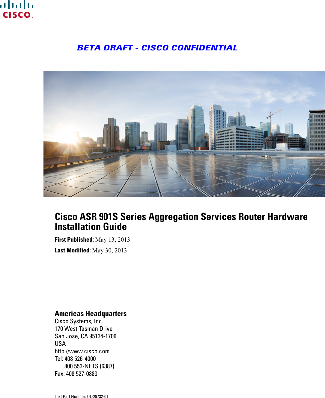
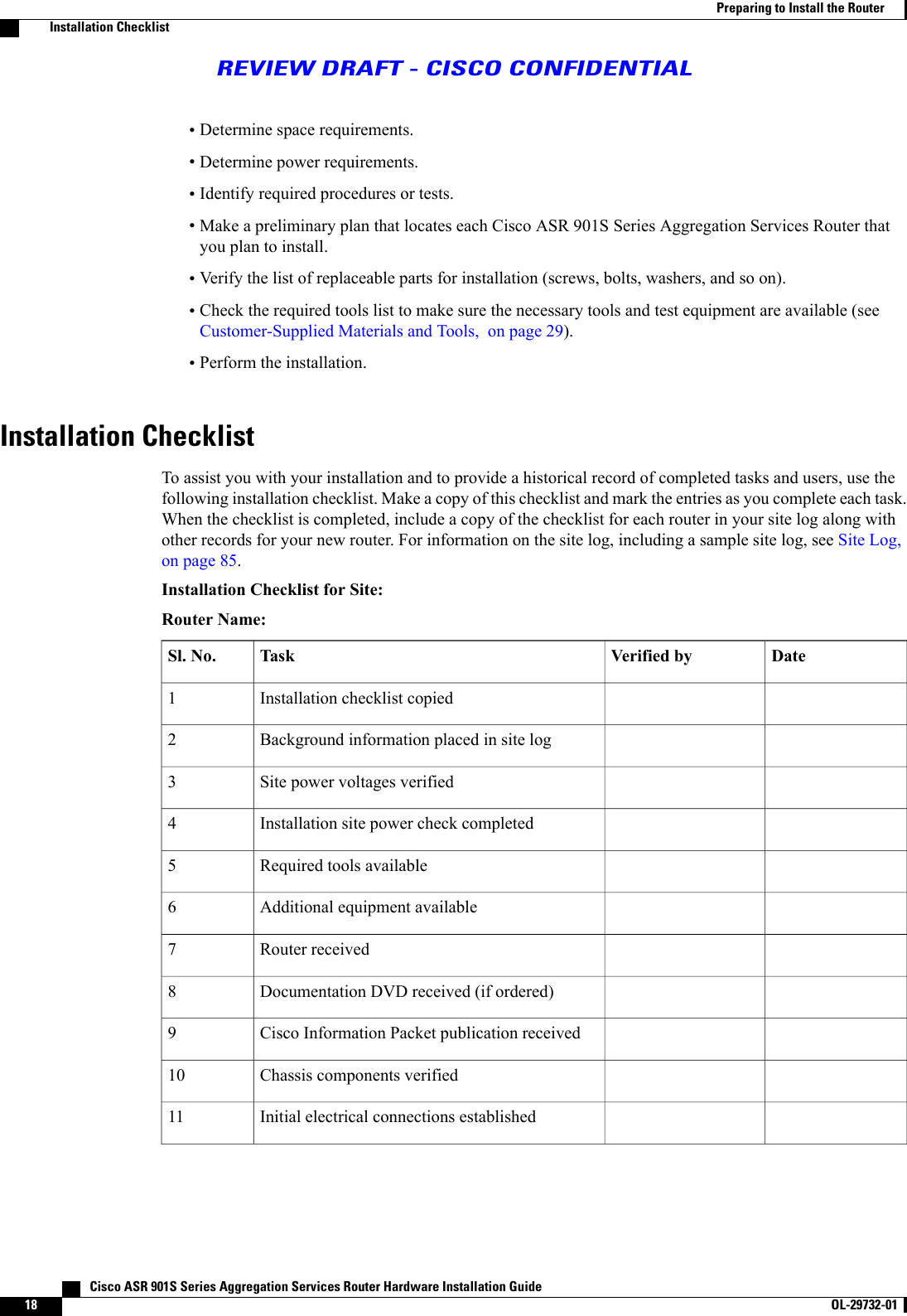
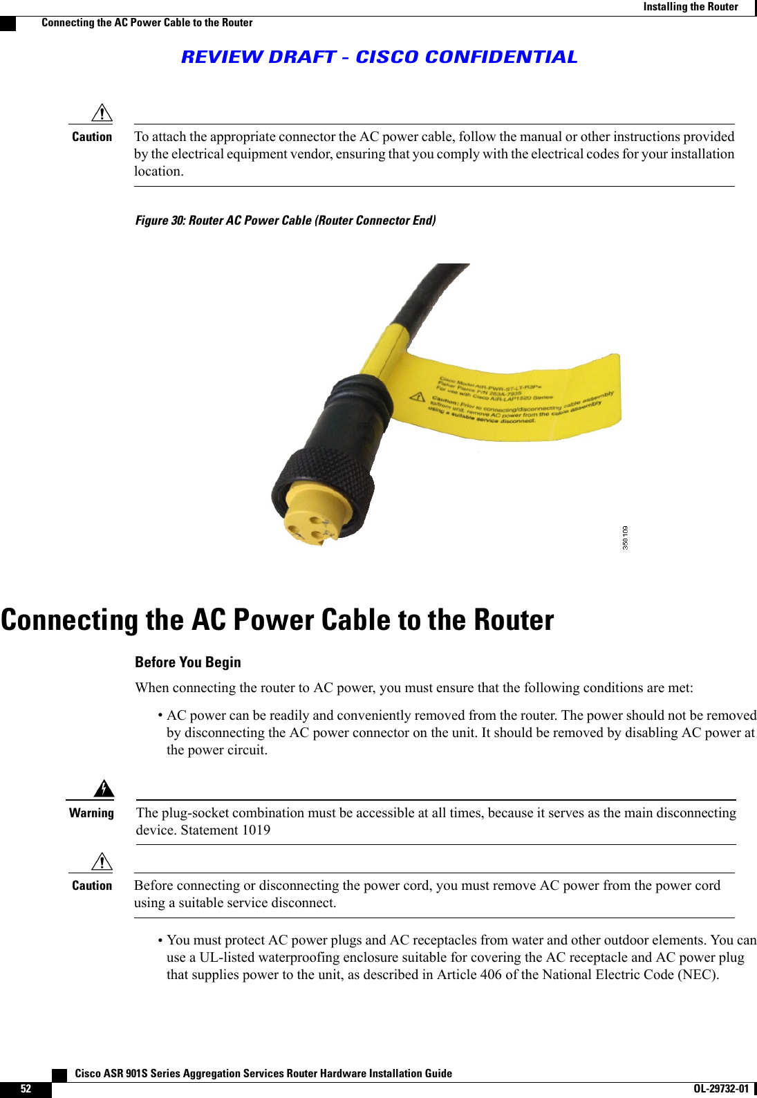
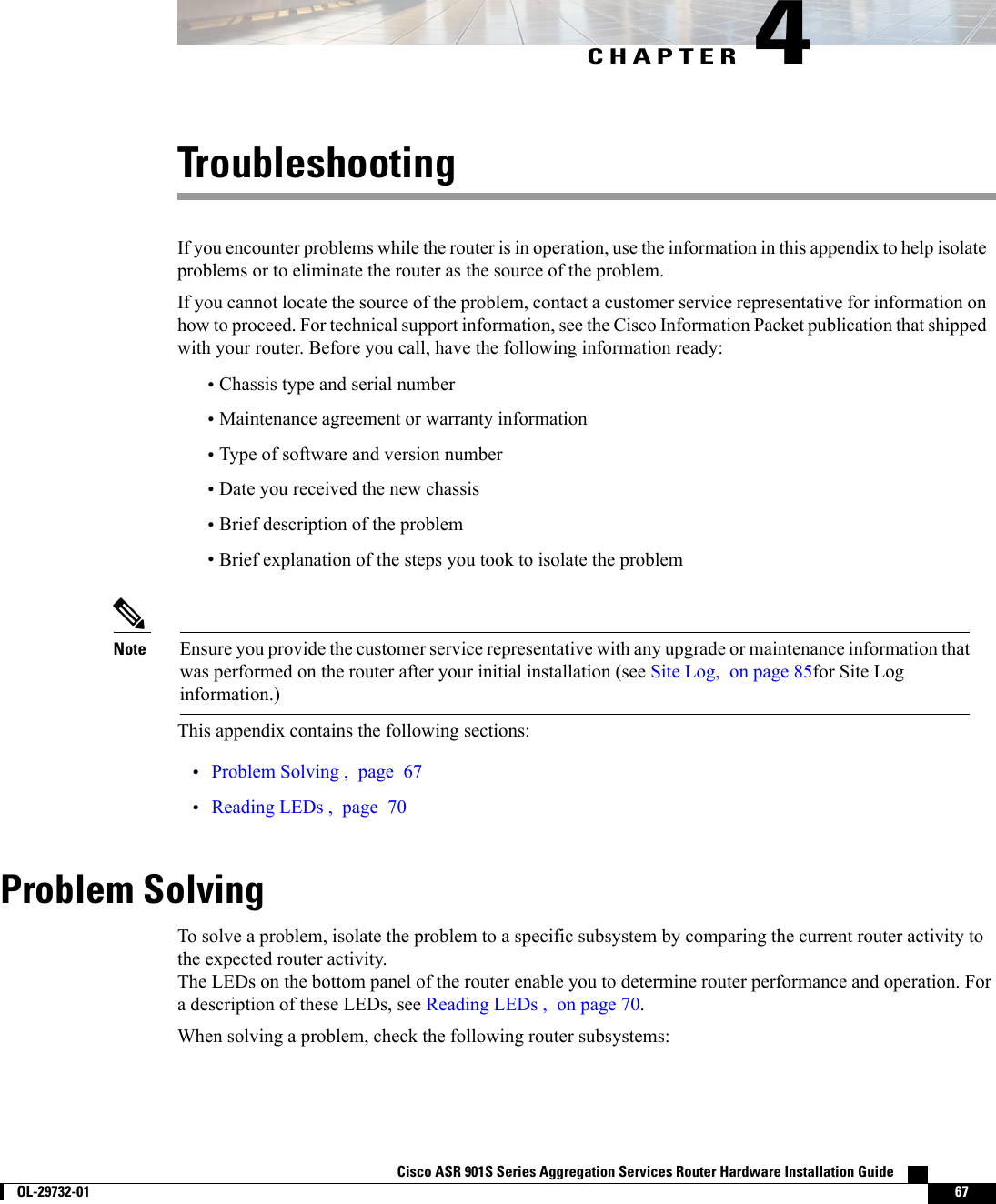
![Describes how to isolate problems, read LEDs,interpret error and status messages, and recoversoftware images.TroubleshootingChapter 4Provides information on part numbers of the routervariants, SFP modules, product, power, andenvironmental specifications. It also contains safetyand compliance information.Specifications and Part NumbersAppendix AProvides cable specifications to use if you plan to buildyour own cables.Cable SpecificationsAppendix BProvides a sample site log.Site LogAppendix CConventionsTable 1: Conventions Followed in This DocumentIndicationConventionCommands and keywords and user-entered text appear in bold font.bold fontDocument titles, new or emphasized terms, and arguments for which yousupply values are in italic font.italic fontElements in square brackets are optional.[ ]Required alternative keywords are grouped in braces and separated by verticalbars.{x | y | z }Optional alternative keywords are grouped in brackets and separated byvertical bars.[x|y|z]A nonquoted set of characters. Do not use quotation marks around the stringor the string will include the quotation marks.stringTerminal sessions and information the system displays appear in courierfont.courier fontNonprinting characters such as passwords are in angle brackets.< >Default responses to system prompts are in square brackets.[ ]An exclamation point (!) or a pound sign (#) at the beginning of a line of codeindicates a comment line.!, # Cisco ASR 901S Series Aggregation Services Router Hardware Installation Guideviii OL-29732-01 PrefaceConventionsREVIEW DRAFT - CISCO CONFIDENTIAL](https://usermanual.wiki/Cisco-Systems/AGORA0916.Users-Manual-HIG/User-Guide-2144095-Page-8.png)
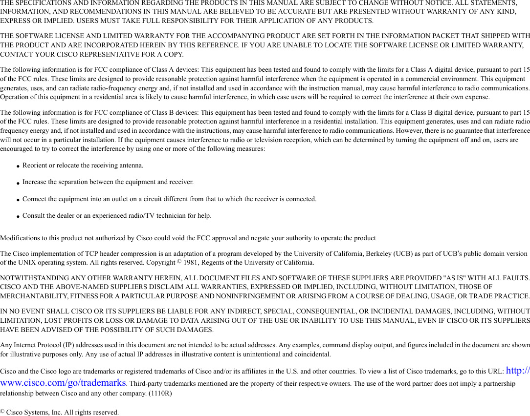
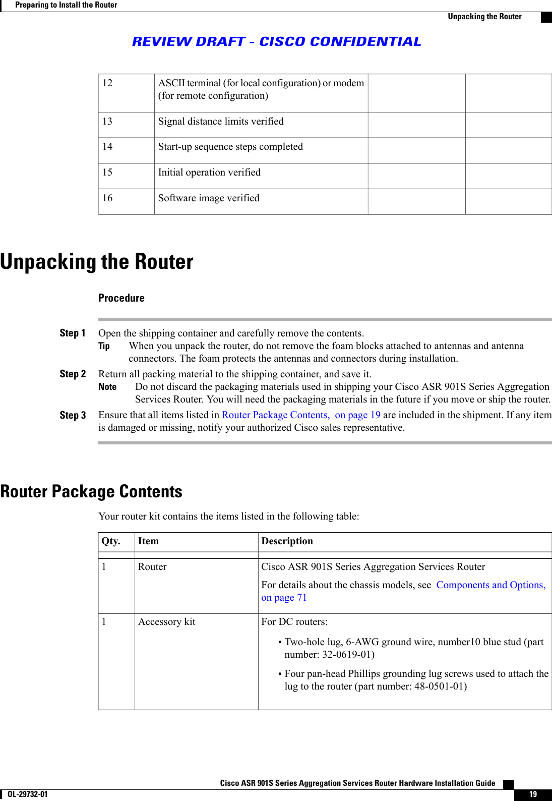
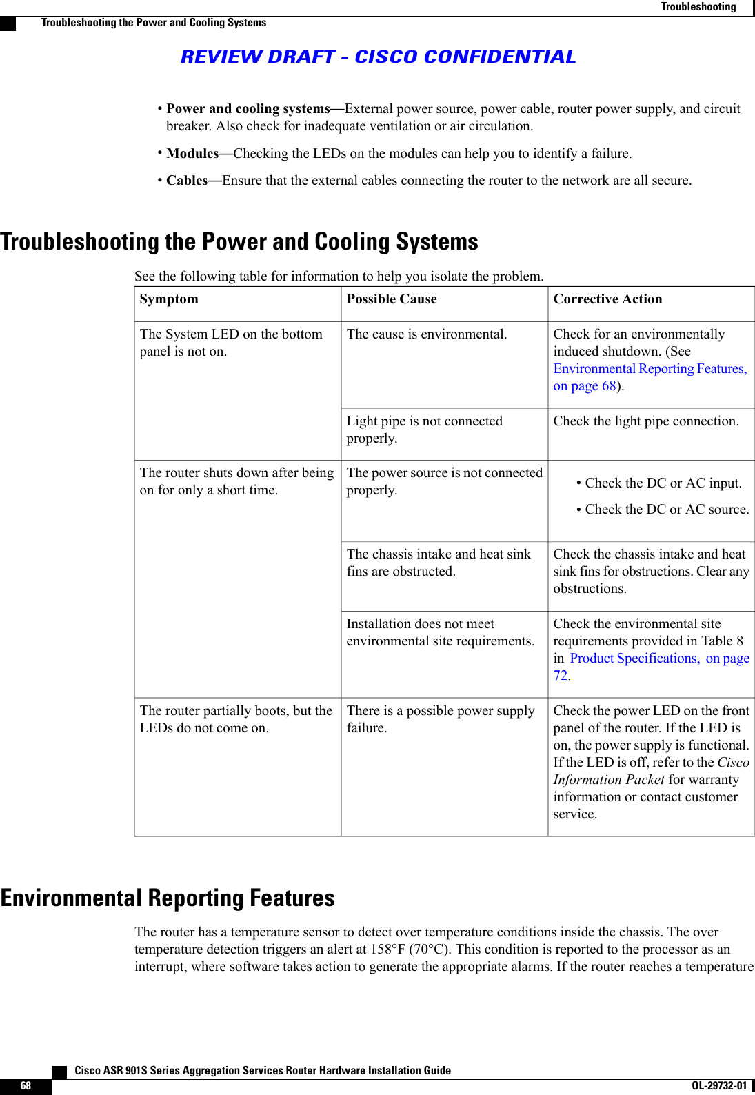
![Means reader take note.NoteMeans the following information will help you solve a problem.TipMeans reader be careful. In this situation, you might perform an action that could result in equipmentdamage or loss of data.CautionMeans reader be warned. In this situation, you might perform an action that could result in bodilyinjury.WarningTable 2: Conventions Followed in This DocumentIndicationConventionCommands and keywords and user-entered text appear in bold font.bold fontDocument titles, new or emphasized terms, and arguments for which yousupply values are in italic font.italic fontElements in square brackets are optional.[ ]Required alternative keywords are grouped in braces and separated by verticalbars.{x | y | z }Optional alternative keywords are grouped in brackets and separated byvertical bars.[x|y|z]A nonquoted set of characters. Do not use quotation marks around the stringor the string will include the quotation marks.stringTerminal sessions and information the system displays appear in courierfont.courier fontNonprinting characters such as passwords are in angle brackets.< >Default responses to system prompts are in square brackets.[ ]An exclamation point (!) or a pound sign (#) at the beginning of a line of codeindicates a comment line.!, #Cisco ASR 901S Series Aggregation Services Router Hardware Installation Guide OL-29732-01 ixPrefaceConventionsREVIEW DRAFT - CISCO CONFIDENTIAL](https://usermanual.wiki/Cisco-Systems/AGORA0916.Users-Manual-HIG/User-Guide-2144095-Page-9.png)
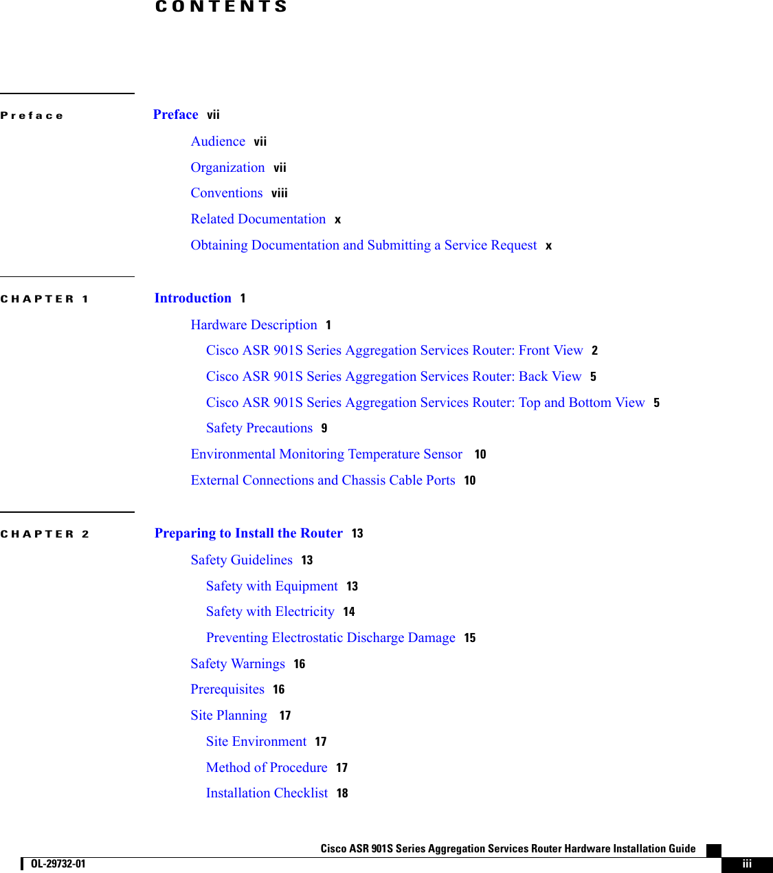
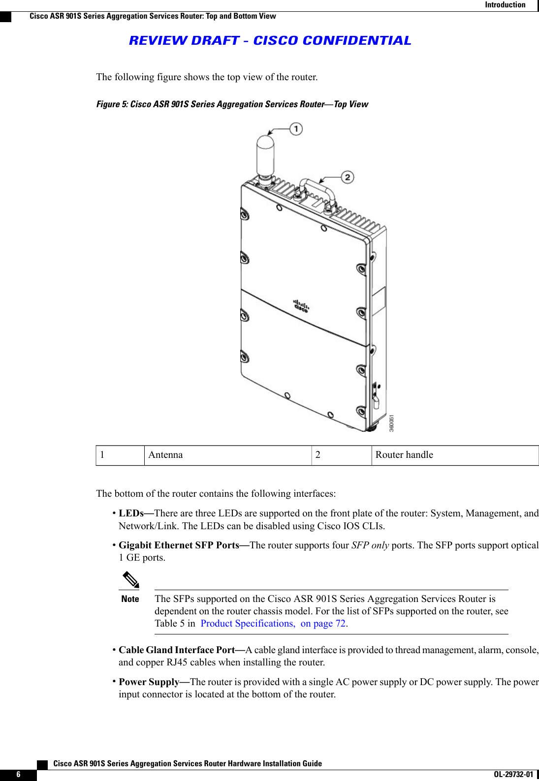
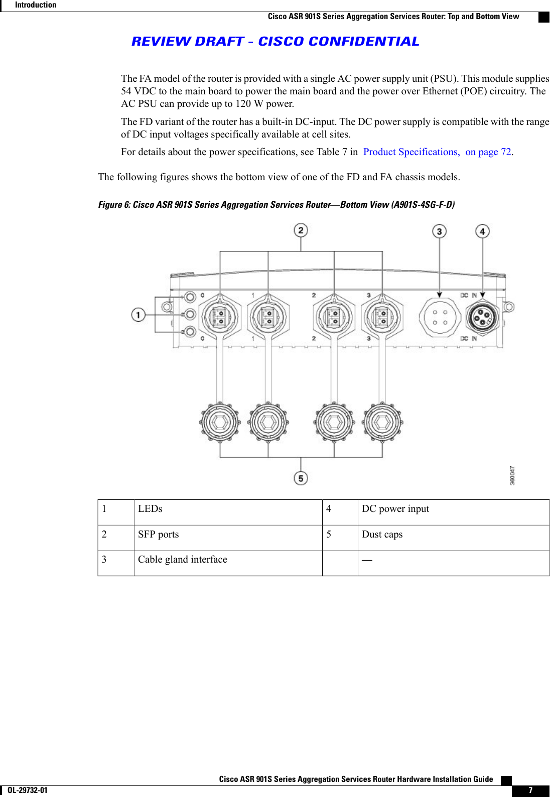
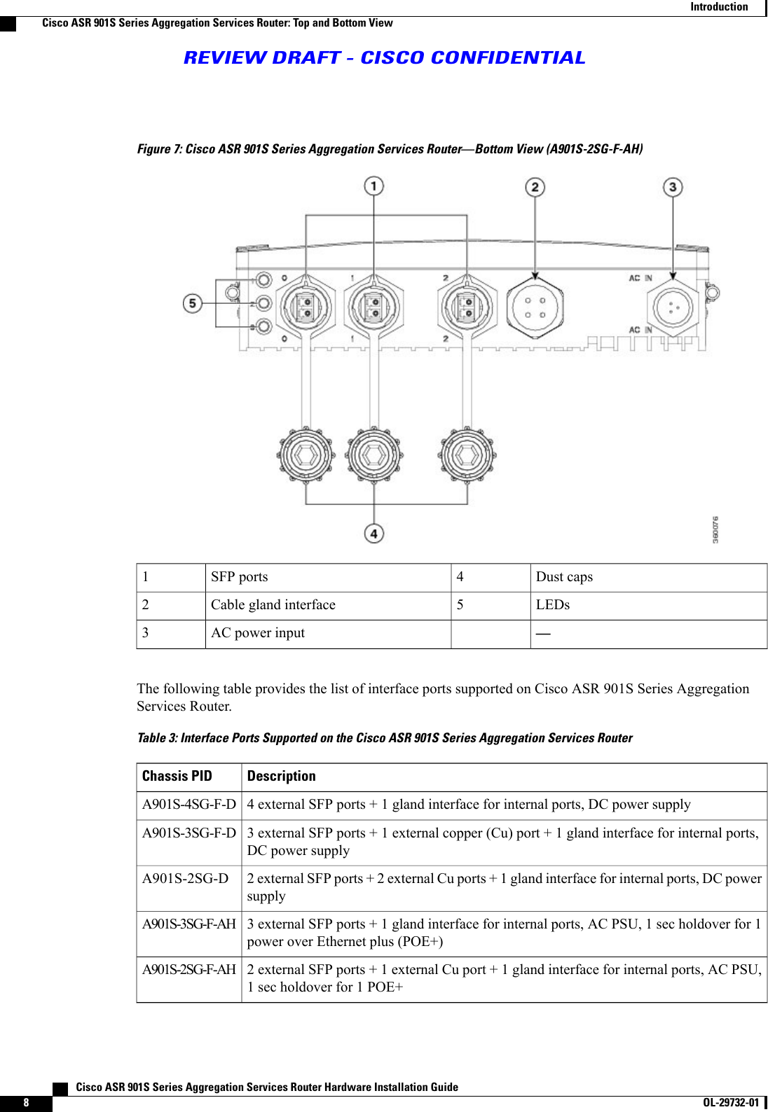
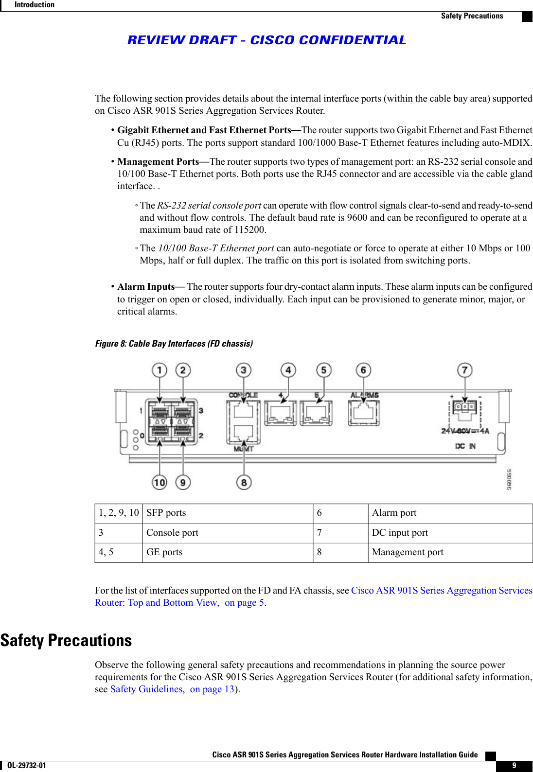
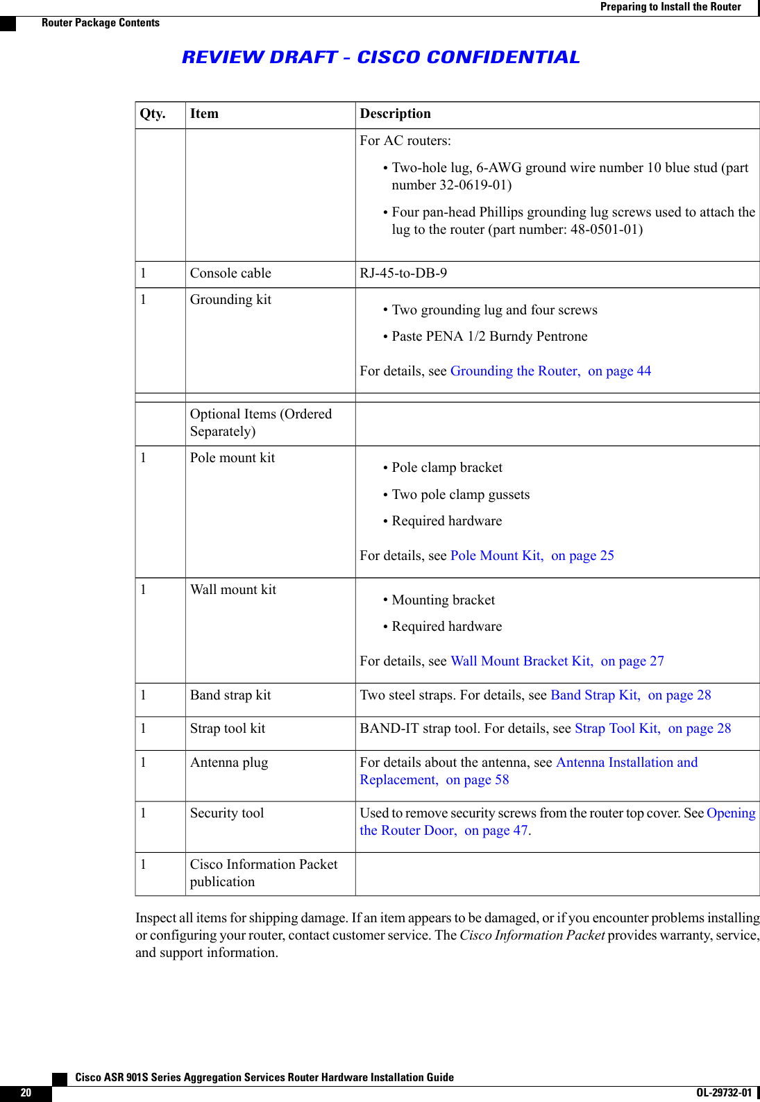
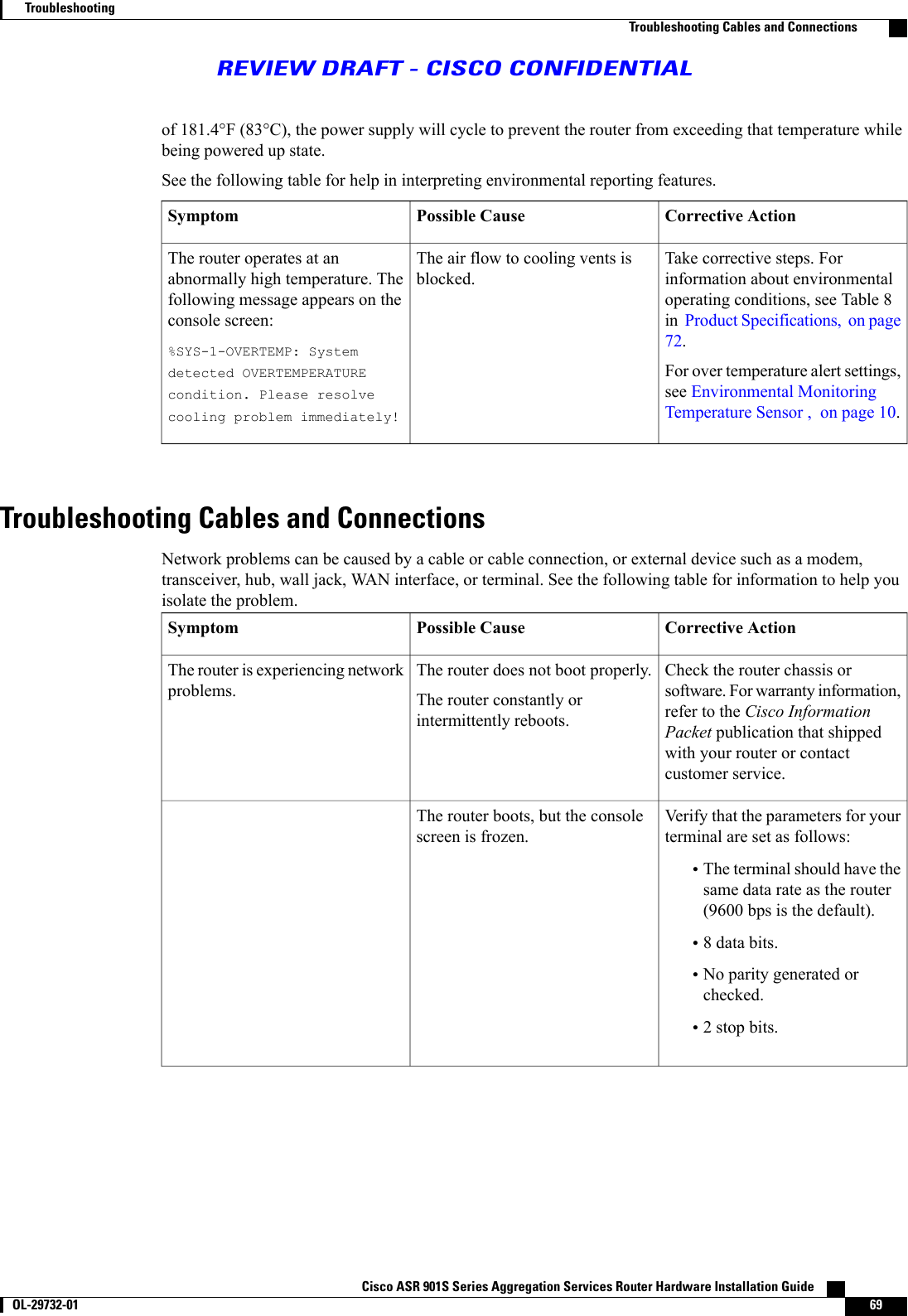
![CHAPTER 1IntroductionThe ASR 901S Series Aggregation Services Router is a small cell, environmentally-hardened (IP65 rated),low-power, cost-effective router. This small cell router (SCR) is designed to support small cell networks toincrease capacity and coverage, thereby reducing operational expenses.These routers provide carrier class metro Ethernet access connectivity in small cell areas and supportpacket-based synchronization based on IEEE1588 and synchronous Ethernet.The ASR 901S Series Aggregation Services Router is compact and can be easily deployed in challenginglocations such as lamp posts, side walls, telephone poles, and cabinets.•Hardware Description, page 1•Environmental Monitoring Temperature Sensor , page 10•External Connections and Chassis Cable Ports, page 10Hardware DescriptionThe ASR 901S Series Aggregation Services Router provides fixed port configuration that is supported on theFD and FA chassis models. These provide fixed 1 GE optical port for backhaul and 1 GE copper (Cu) portfor downstream connectivity.The router weighs 13.2 pounds (5.99 kgs [FD chassis model with two SFPs and antenna]) or 15. 8 pounds(7.2 kgs [FA chassis model with two SFPs and antenna]). It measures 16 inches high x 11 inches wide x 2.5inches deep (40.64 cm x 27.94 cm x 6.35 cm).For information about the chassis models for the ASR 901S Series Aggregation Services Router, seeComponents and Options, on page 71.The ASR 901S Series Aggregation Services Routers provide the following hardware features:•Four optical GE ports•Two Cu 10/100/1000BASE-T ports•One management Ethernet port•One console port•One alarm port with four dry-alarm inputsCisco ASR 901S Series Aggregation Services Router Hardware Installation Guide OL-29732-01 1](https://usermanual.wiki/Cisco-Systems/AGORA0916.Users-Manual-HIG/User-Guide-2144095-Page-11.png)
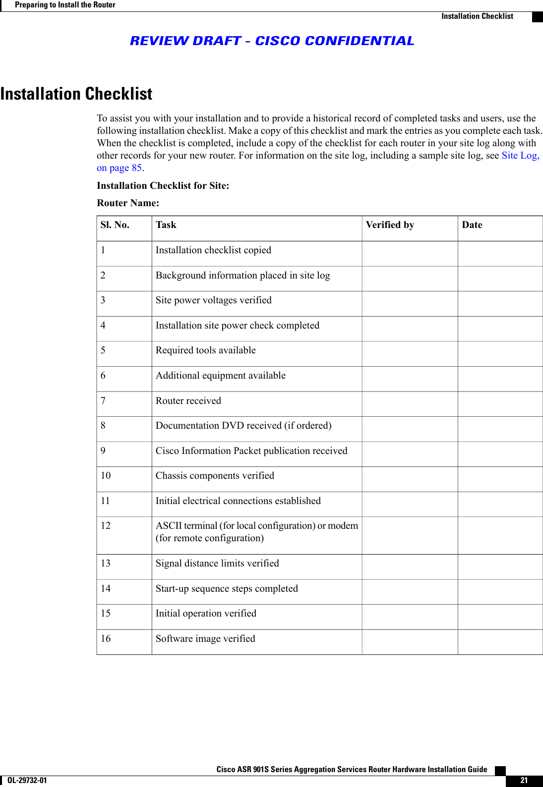
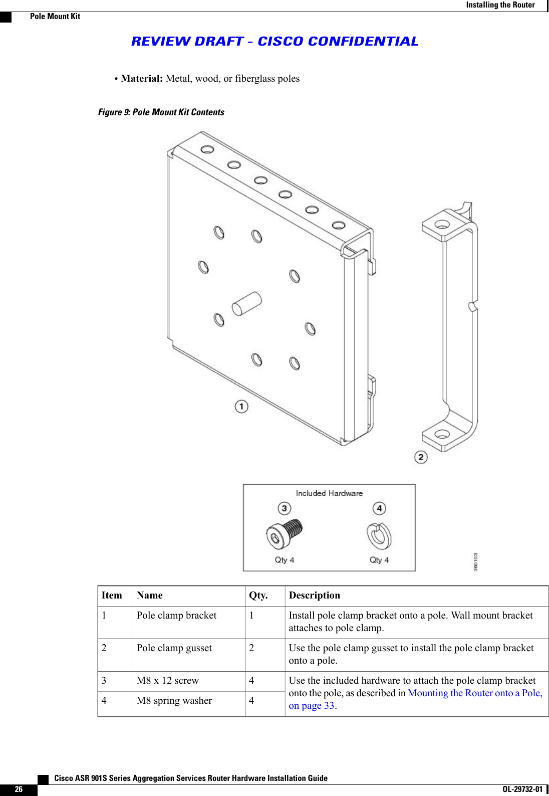
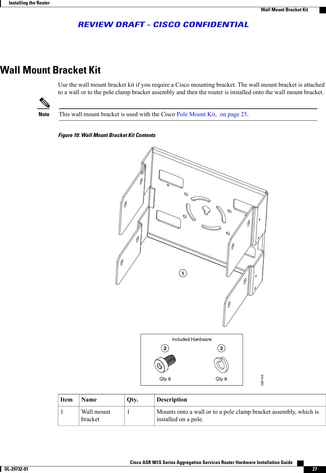
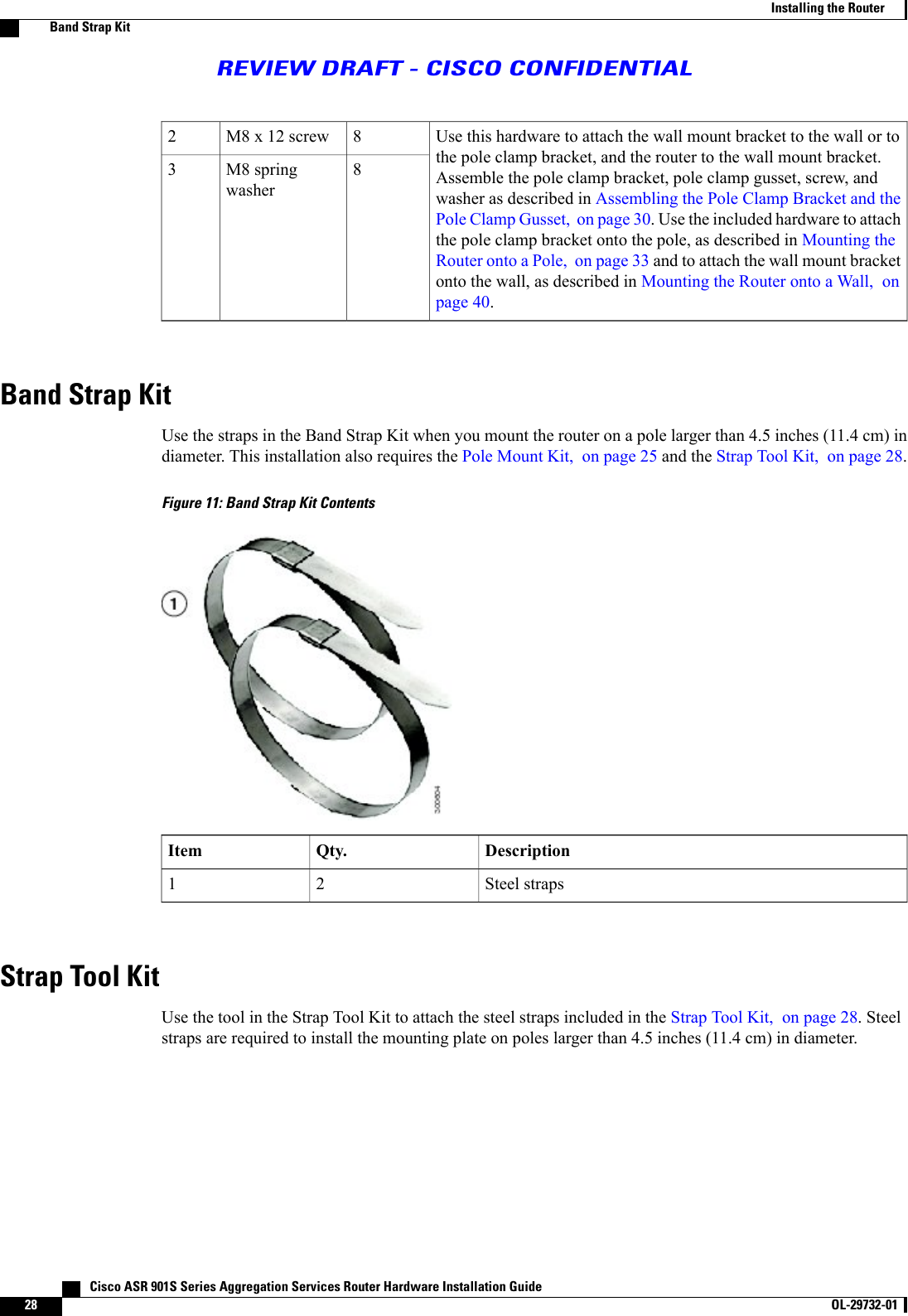
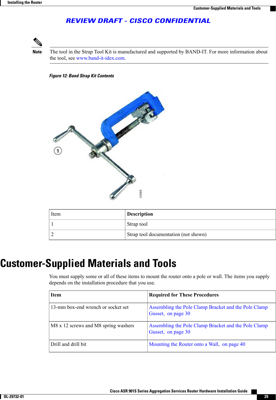
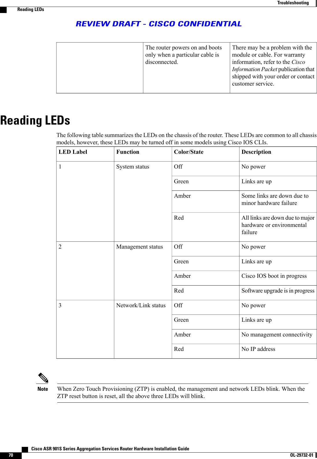
![The includes a detailed description of each kit.DescriptionNameCisco Product ID(PID)This kit is required if your installation requires a Ciscomounting bracket to mount the router. This kit is includedWall Mount BracketKit, on page 27-with the router accessory kit, and is used with the pole kitand includes the hardware required to attach the mountingbracket onto the pole clamp bracket.This kit is required for all pole or streetlight installationsand includes a mounting bracket, pole clamp bracket, polePole Mount Kit, onpage 25CGR-PMK1000clamp gusset, and the hardware required to attach the poleclamp bracket assembly to a pole.This kit includes two steel straps for mounting the router onpoles larger than 5 inches (14 cm) in diameter. This kit isBand Strap Kit, onpage 28CGR-PMK-BANDused together with the Pole Mount Kit, on page 25. ABand-It Tool is required to install the steel straps on a pole.This kit includes a Band-It tool that is required when usingsteel straps to install the router on poles larger than 4.5 inches(11.4 cm) in diameter.Strap Tool Kit, onpage 28AIR-BAND-INST-TL=General Safety Information for MountingBefore performing any of the tasks in this chapter, read the safety warnings in this section and the SafetyGuidelines, on page 13.Two technicians are required to properly and safely mount the router.All mounting methods at any location are subject to the acceptance of local jurisdiction.CautionThe mounting surface, attaching screws, and optional wall anchors must be able to support 13.2 pounds(5.99 kgs [FD chassis model with two SFPs and antenna]) or 15. 8 pounds (7.2 kgs [FA chassis modelwith 2 SFPs and antenna]) static weight.CautionPersonnel mounting the router must understand grounding methods.Caution Cisco ASR 901S Series Aggregation Services Router Hardware Installation Guide24 OL-29732-01 Installing the RouterGeneral Safety Information for MountingREVIEW DRAFT - CISCO CONFIDENTIAL](https://usermanual.wiki/Cisco-Systems/AGORA0916.Users-Manual-HIG/User-Guide-2144095-Page-34.png)
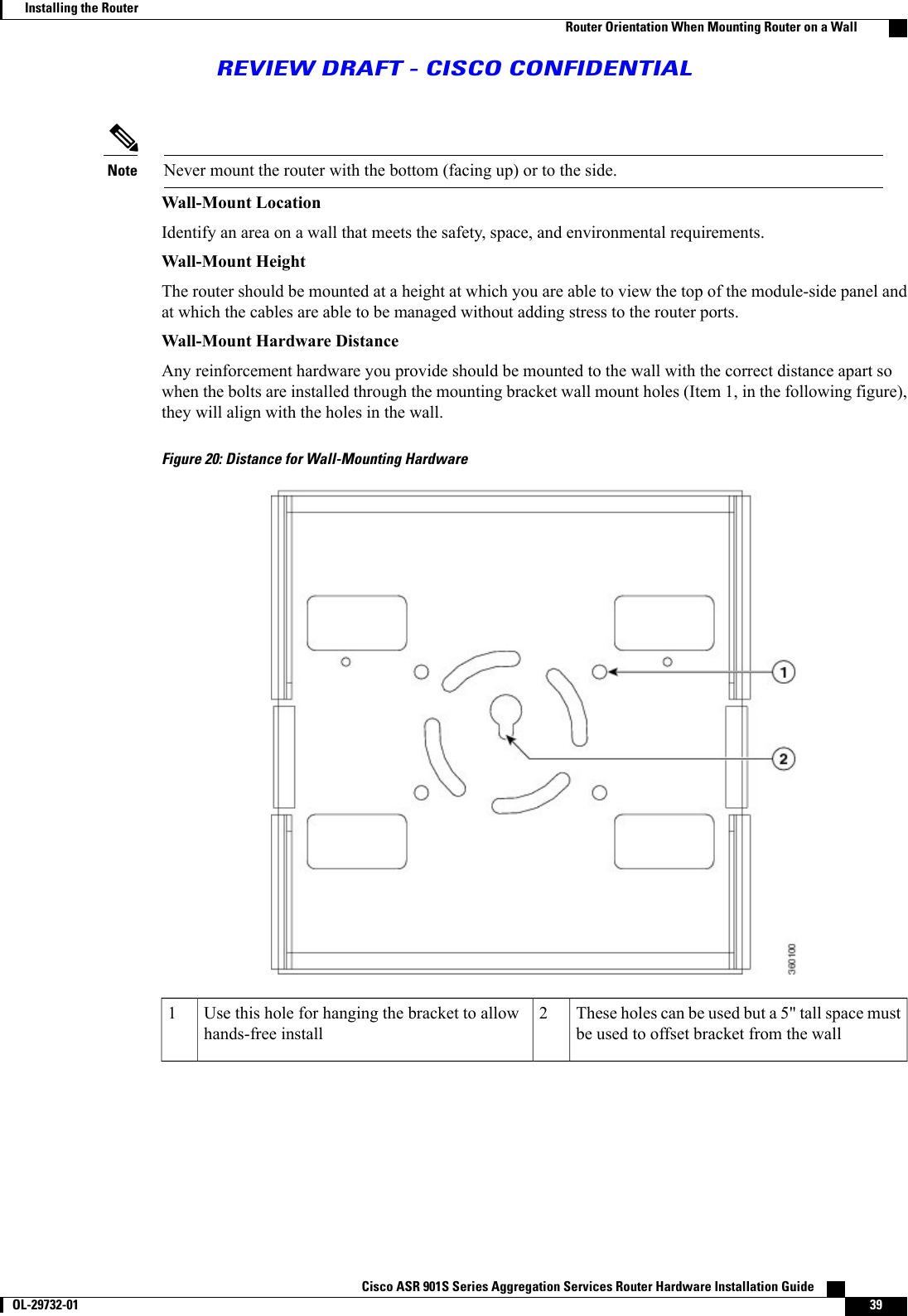
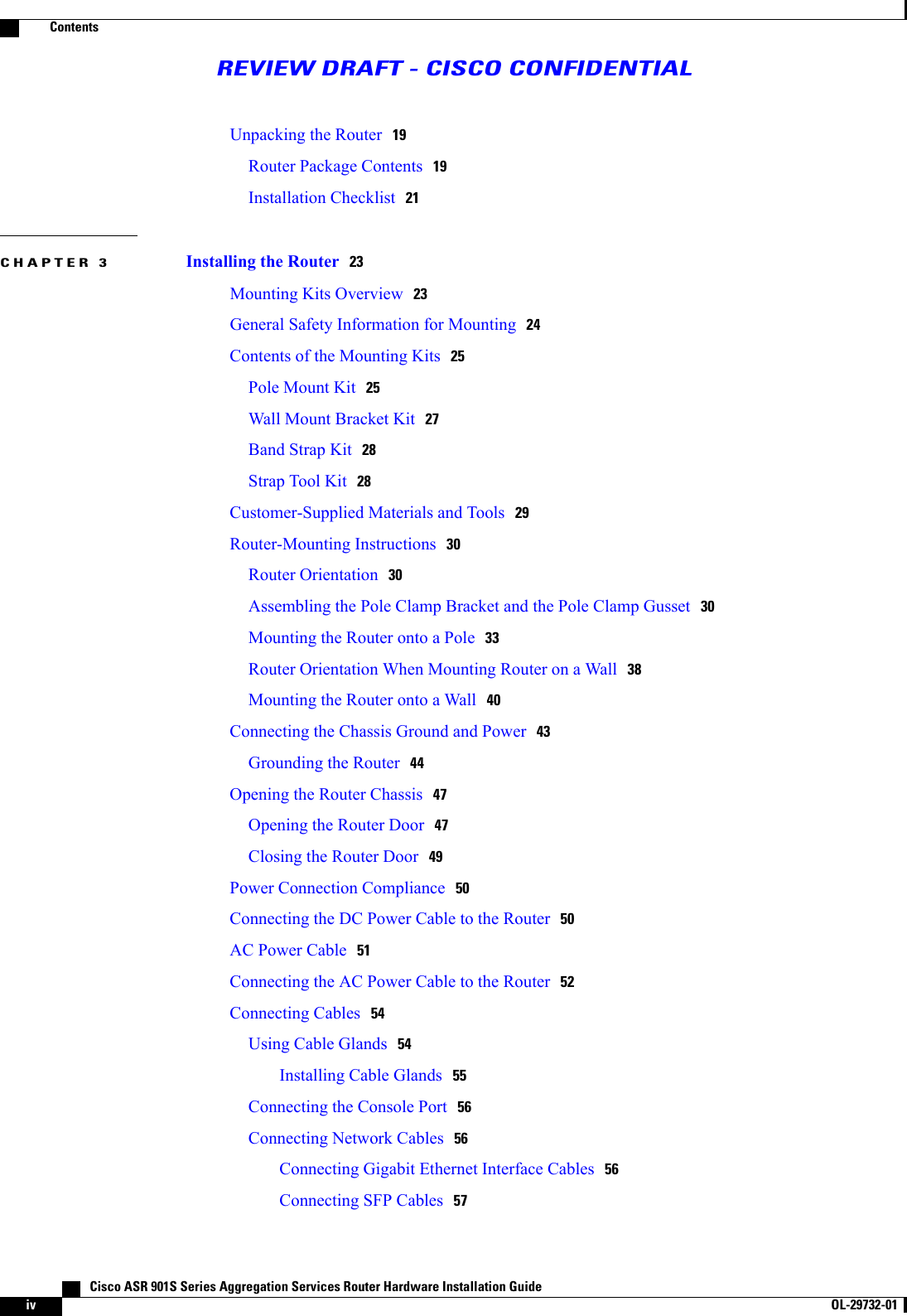
![The mounting surface, attaching screws, and optional wall anchors must be able to support 13.2pounds (5.99 kgs [FD chassis model with two SFPs and antenna]) or 15. 8 pounds (7.2 kgs [FAchassis model with 2 SFPs and antenna]) static weight.CautionFigure 21: Wall Mount Bracket for Wall-MountingStep 2 Use four customer-supplied screws and optional screw anchors to attach the wall mount bracket to the mountingsurface.If necessary, use suitable screw anchors and an exterior-grade plywood backboard to mount the routerto a stucco, cement, or dry wall.NoteCisco ASR 901S Series Aggregation Services Router Hardware Installation Guide OL-29732-01 41Installing the RouterMounting the Router onto a WallREVIEW DRAFT - CISCO CONFIDENTIAL](https://usermanual.wiki/Cisco-Systems/AGORA0916.Users-Manual-HIG/User-Guide-2144095-Page-51.png)
![Using CLIs for Flash Memory and Directory ProceduresThe following sections contain the formatting procedures for flash memory and file and directory proceduresusing Cisco IOS CLIs.Formatting Procedures for Flash MemoryWe recommend that you erase the (Class B) flash memory to initialize with a Class B flash file system.The Class B flash file system is also known as the low end file system (LEFS).Formatting Flash Memory as a DOS File SystemTo format the flash memory or to remove the files from it, use the erase flash: command.The following is sample output for formatting the flash memory, formatted with a Class B flash file system:Router# erase flash :Erasing the flash filesystem will remove all files! Continue? [confirm]eeeeeeeeeeeeeeeeeeeeeeeeeeeeeeeeeeeeeeeeeeeeeeeeeeeeeeeeeeeeeeeeeeeeeeeeeeeeeeeeeeeeeeeeeeeeeeeeeeeeeeeeeeeeeeeeeeeeeeeeeeeeeeeeeeeeeeeeeeeeeeeeeeeeeeeeeeeeeeeeeeeeeeeeeeeeeeeeeeeeeeeeeeeeeeeeeeeeeeeeeeeeeeeeeeeeeeeeeeeeeeeeeeeeeeeeeeeeeeeeeeeeeeeeeeeeeeeeeeeeeeeeeeeeeeeeeeeeeeeeeeeeeeeeeeeeeeeeeeeeeeeeeeeeeeeeeeeeeeeeeeeeeeeeeeeeeeeeeeeeeeeeeeeeeeeeeeeeeeeeeeeeeeeeeeeeeeeeeeeeeeeeeeeeeeeeeeeeeeeeeeeeeeeeeeeeeeeeeeeeeeeeeeeeeeeeeee...erasedErasing deviceFile and Directory ProceduresThe following sections describe file and directory procedures for flash memory, formatted with a Class Bflash file system.Copying FilesTo copy files to another location, use the copy tftp:flash: command.The following is sample output for copying the file from an external location to the internal flash memory.Router# copy tftp: flashAddress or name of remote host []? 10.64.71.240Source filename []? /ngmwr-advipservicesk9-mzDestination filename [ngmwr-advipservicesk9-mz]?Accessing tftp://10.64.71.240//ngmwr-advipservicesk9-mz...Erase flash: before copying? [confirm]nLoading /ngmwr-advipservicesk9-mz from 10.64.71.240 (via FastEthernet0/0):!!!!!!!!!!!!!!!!!!!!!!!!!!!!!!!!!!!!!!!!!!!!!!!!!!!!!!!!!!!!!!!!!!!!!!!!!!!!!!!!!!!!!!!!!!!!!!!!!!!!!!!!!!!!!!!!!!!!!!!!Cisco ASR 901S Series Aggregation Services Router Hardware Installation Guide OL-29732-01 63Installing the RouterUsing CLIs for Flash Memory and Directory ProceduresREVIEW DRAFT - CISCO CONFIDENTIAL](https://usermanual.wiki/Cisco-Systems/AGORA0916.Users-Manual-HIG/User-Guide-2144095-Page-73.png)
![[OK - 30480936 bytes]Verifying checksum... OK (0xA6AD)30480936 bytes copied in 196.968 secs (154751 bytes/sec)Displaying Contents of the Flash MemoryTo display the contents (directories and files) of the flash memory formatted with a Class B flash file system,use the dir: command.The following is sample output for displaying the contents of the flash memory with a Class B flash filesystem:Router# dirDirectory of flash:/1 -rw- 30564420 <no date> ngmwr-advipservicesk9-mz2 -rw- 30564420 <no date> ngmwr-backup83623932 bytes total (22494964 bytes free)Deleting Files from the Flash MemoryTo delete a file from the flash memory, use the delete: filename command followed by the squeeze flash:command.When a file is deleted in the Class B flash file system, the memory space occupied by the deleted file is notreleased until you use the squeeze command. Although the memory space once occupied by the deleted fileremains, the deleted file cannot be recovered. To release the memory space occupied by a deleted file, enterthe squeeze flash: command.The following is sample output for deleting a Cisco IOS file from the flash memory, and releasing the memoryspace originally occupied by the file.Router# dirDirectory of flash:/1 -rw- 30564420 <no date> ngmwr-advipservicesk9-mz2 -rw- 30564420 <no date> ngmwr-backup2 -rw- 30564420 <no date> ngmwr-backupRouter# delete ngmwr-advipservicesk9-mzDelete filename [ngmwr-advipservicesk9-mz]?Delete flash:ngmwr-advipservicesk9-mz? [confirm]Router# show flash :les_flash_info : 1006 :File Length Name/status1 30564420 ngmwr-advipservicesk9-mz [deleted]2 30564420 ngmwr-backup[61128968 bytes used, 22494964 available, 83623932 total] Cisco ASR 901S Series Aggregation Services Router Hardware Installation Guide64 OL-29732-01 Installing the RouterFile and Directory ProceduresREVIEW DRAFT - CISCO CONFIDENTIAL](https://usermanual.wiki/Cisco-Systems/AGORA0916.Users-Manual-HIG/User-Guide-2144095-Page-74.png)
![81920K bytes of processor board System flash (Read/Write)Router# squeeze flash :Squeeze operation may take a while. Continue? [confirm]squeeze in progress...eeeeeeeeeeeeeeeeeeeeeeeeeeeeeeeeeeeeeeeeeeeeeeeeeeeeeeeeeeeeeeeeeeeeeeeeeeeeeeeeeeeeeeeeeeeeeeeeeeeeeeeeeeeeeeeeeeeeeeeeeeeeeeeeeeeeeeeeeeeeeeeeeeeeeeeeeeeeeeeeeeeeeeeeeeeeeeeeeeeeeeeeeeeeeeeeeeeeeeeeeeeeeeeeeeeeeeeeeeeeeeeeeeeeeeeeeeeeeeeeeeeeeeeeeeeeeeeeeeeeeeeeeeeeeeeeeeeeeeeeeeeeeeeeeeeeeeeeeeeeeeeeeeeeeeeeeeeeeeeeeeeeeeeeeeeeeeeeeeeeeeeeeeeeeeeeeeeeeeeeeeeeeeeeeeeeeeeeeeeeeeeeeeeeeeeeeeeeeeeeeeeeeeeeeeeeeeeeeeeeeeeeeeeeeeeeeeeeeeeeeeeeeeeeeeeeeeeeeeeeeeeeeeeeeeeeeeeeeeeeeeeeeeeeeeeeeeeeeeeeeeeeeeeeeeeeeeeeeeeeeeeeeeeeeeeeeeeeeeeeeeeeeeeeeeeeeeeeeeeeeeeeeeeeeeeeeeeeeeeeeeeeeeeeeeeeeeeeeeeeeeeeeeeeeeeeeeeeeeeeeeeeeeeeeeeeeeeeeeeSqueeze of flash completeRouter# dirDirectory of flash:/2 -rw- 30564420 <no date> ngmwr-backup83623932 bytes total (22661932 bytes free)Displaying File ContentTo display the contents of a file in the flash memory, use the more flash: filename command.The following is sample output from the more flash command on a flash card:Router# more flash:ngmwr-advipservicesk9-mz00000000: 7F454C46 01020100 00000000 00000000 .ELF .... .... ....00000010: 00020061 00000001 80008000 00000034 ...a .... .... ...400000020: 00000054 20000001 00340020 00010028 ...T ... .4. ...(00000030: 00050008 00000001 0000011C 80008000 .... .... .... ....00000040: 80008000 00628A44 00650EEC 00000007 .... .b.D .e.l ....00000050: 0000011C 0000001B 00000001 00000006 .... .... .... ....00000060: 80008000 0000011C 00004000 00000000 .... .... ..@. ....00000070: 00000000 00000008 00000000 00000021 .... .... .... ...!00000080: 00000001 00000002 8000C000 0000411C .... .... ..@. ..A.00000090: 00000700 00000000 00000000 00000004 .... .... .... ....000000A0: 00000000 00000029 00000001 00000003 .... ...) .... ....000000B0: 8000C700 0000481C 00000380 00000000 ..G. ..H. .... ....000000C0: 00000000 00000004 00000000 0000002F .... .... .... .../Cisco ASR 901S Series Aggregation Services Router Hardware Installation Guide OL-29732-01 65Installing the RouterFile and Directory ProceduresREVIEW DRAFT - CISCO CONFIDENTIAL](https://usermanual.wiki/Cisco-Systems/AGORA0916.Users-Manual-HIG/User-Guide-2144095-Page-75.png)
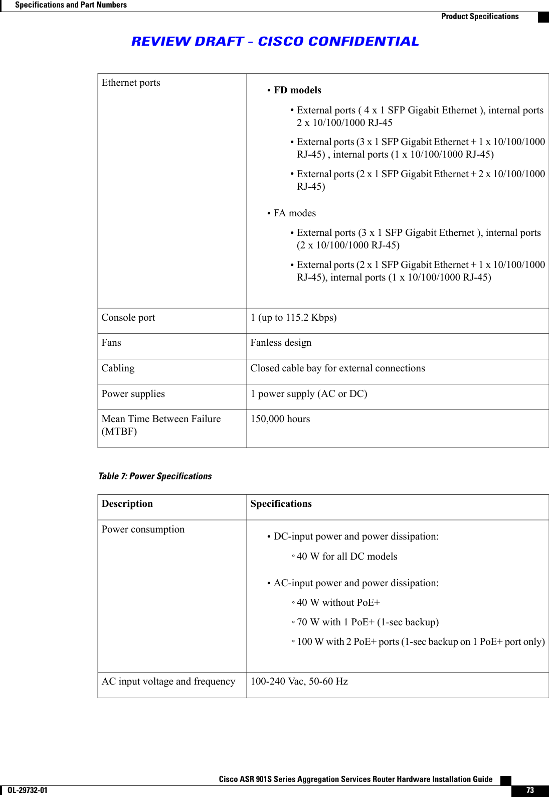
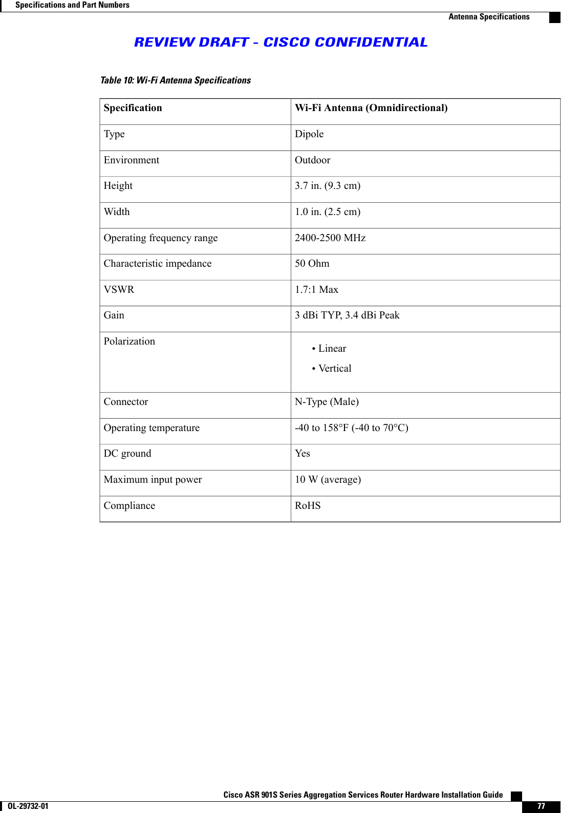
![The router supports a wide range of SFP optics modules. The following table lists their part numbers. Theoperational temperatures supported for the optics are defined by individual SFP or SFP+ modules.Table 5: SFP Modules SupportedPart NumberTypeGLC-LH-SM, GLC-LH-SMD, GLC-EX-SMD, GLC-T,GLC-ZX-SMD, GLC-LX-SM-RGD, GLC-SX-MM,GLC-SX-MMD, GLC-SX-MM-RGD, GLC-ZX-SM,GLC-ZX-SM-RGD, GLC-BX-U, GLC-BX-D, SFP-GE-L,SFP-GE-S, SFP-GE-Z, SFP-GE-T, GLC-FE-100FX-RGD,CWDM-SFP-1470, CWDM-SFP-1490,CWDM-SFP-1510, CWDM-SFP-1530,CWDM-SFP-1550, CWDM-SFP-1570,CWDM-SFP-1590, CWDM-SFP-1610, ranging fromDWDM-SFP-3033 to DWDM-SFP-6141 (40 wavelengths)Ethernet SFPProduct SpecificationsThe following tables list product, power, and environmental specifications, and safety and complianceinformation for the Cisco ASR 901S Series Aggregation Services Router.Table 6: Cisco ASR 901S Series Aggregation Services Router SpecificationsSpecificationsDescription16 inches high x 11 inches wide x 2.5 inches deep (40.64 cm x 27.94cm x 6.35 cm)Dimensions (H x W x D)•Approximately 11. 7 lbs. (5.8 kgs [FD chassis model])•Approximately14.9 lbs. (6.8 kgs [FA chassis model])Weight•Flash memory: 128 MB (onboard flash)•System memory: 512 MB (DDR3)Memory•Lamp post mount kit•Wall mount kit•H-frame mount kitRack-mount options Cisco ASR 901S Series Aggregation Services Router Hardware Installation Guide72 OL-29732-01 Specifications and Part NumbersProduct SpecificationsREVIEW DRAFT - CISCO CONFIDENTIAL](https://usermanual.wiki/Cisco-Systems/AGORA0916.Users-Manual-HIG/User-Guide-2144095-Page-82.png)