Cisco Systems BTS-TP1 Ripwave TTA Base Station User Manual ttaicguide
Cisco Systems, Inc Ripwave TTA Base Station ttaicguide
UserManual.wiki
>
Cisco Systems
>
BTS-TP1 User Manual
>
User Manual Section 1
Contents
1.
User Manual Section 1
2.
User Manual Section 2
User Manual Section 1
Navigation menu
Upload a User Manual
Namespaces
Wiki Guide
HTML
PDF
Info
Views
User Manual
Discussion / Help
Navigation
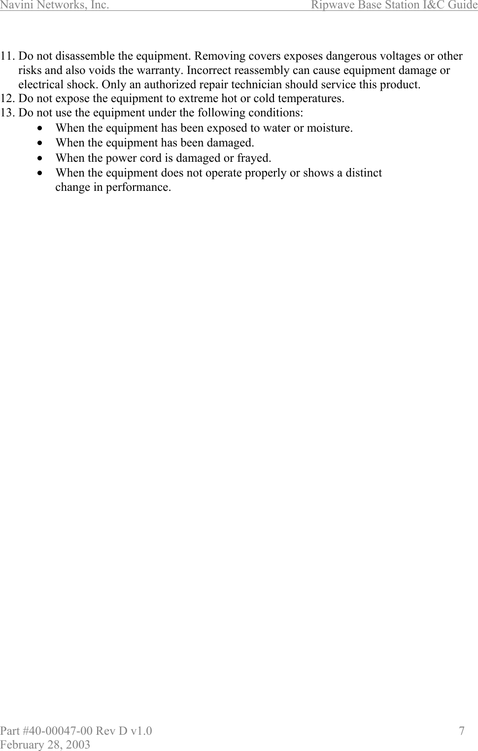
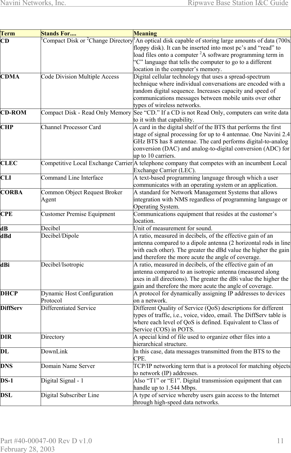
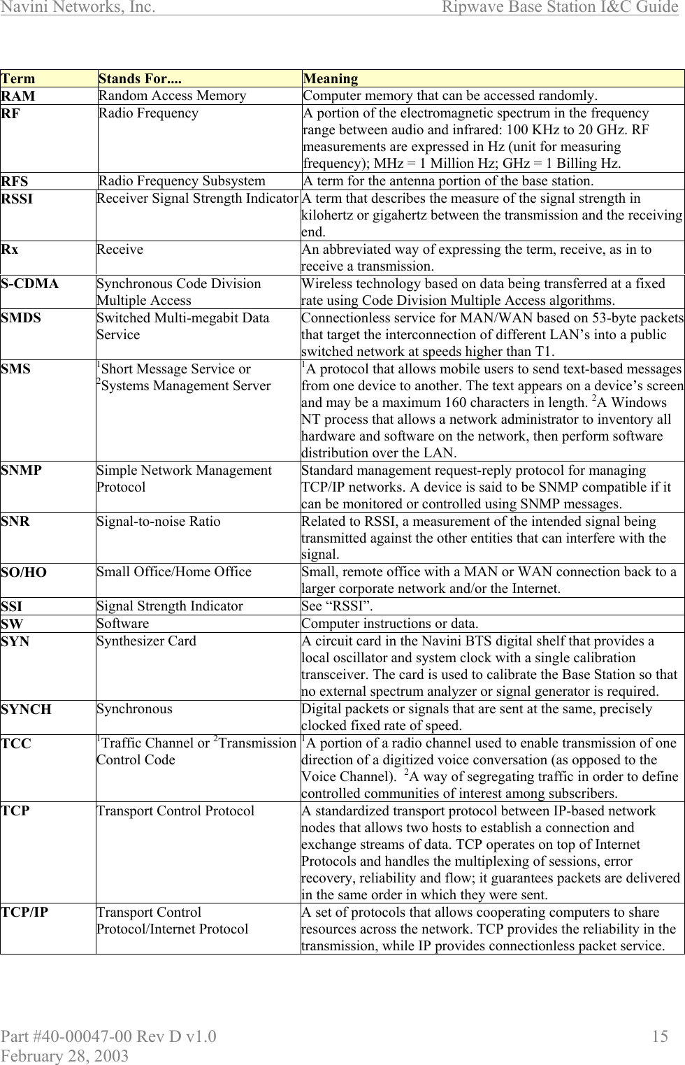
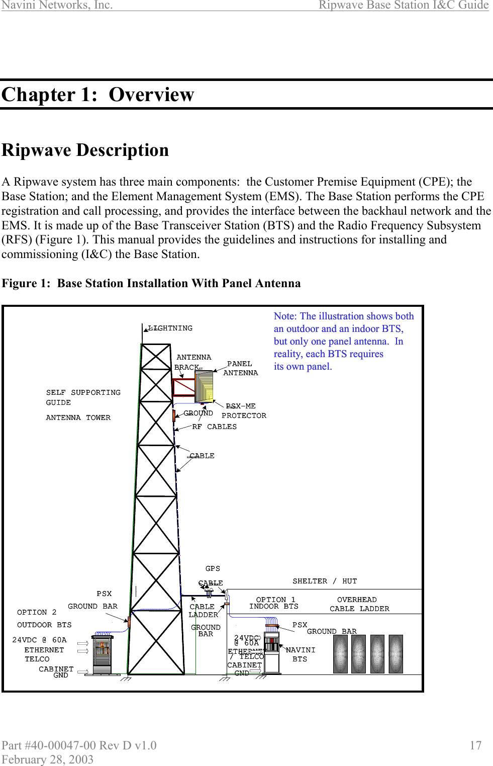
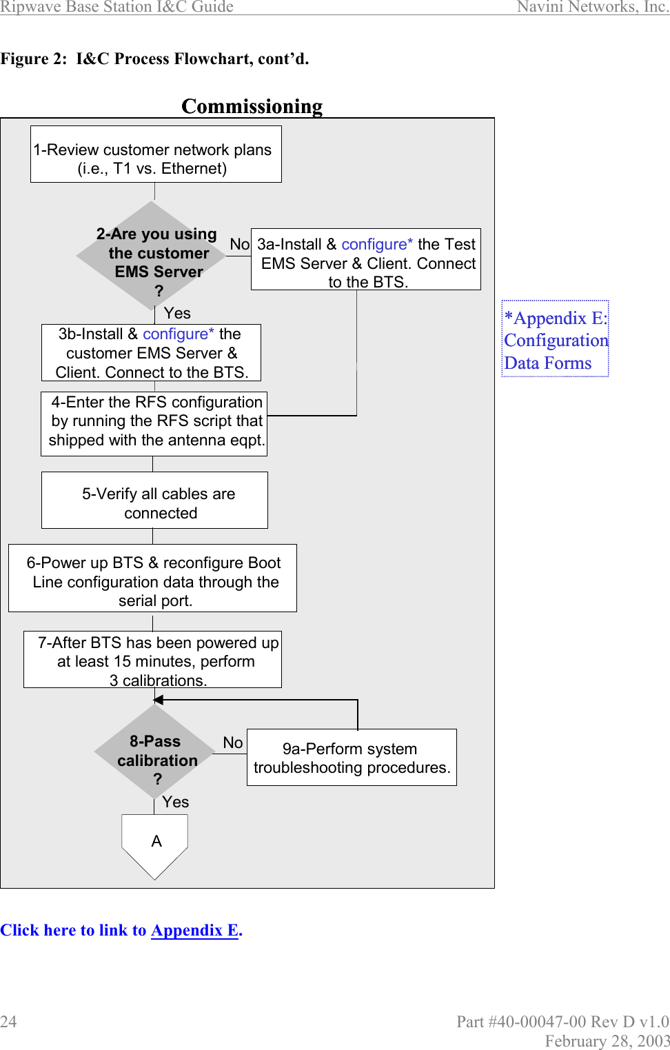
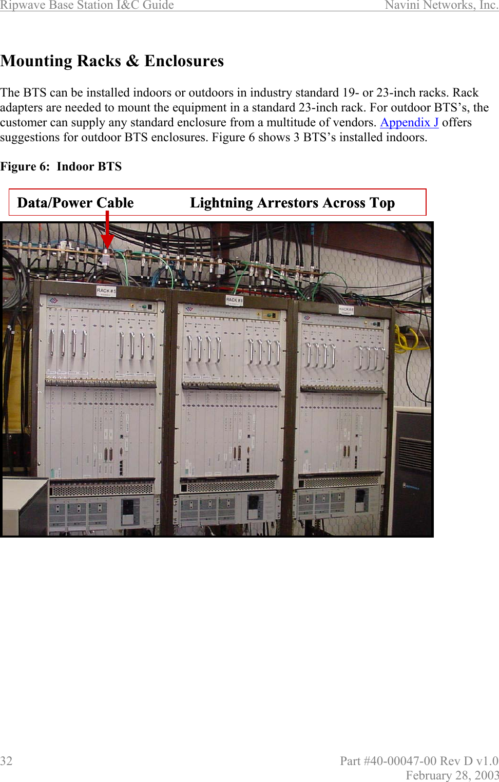
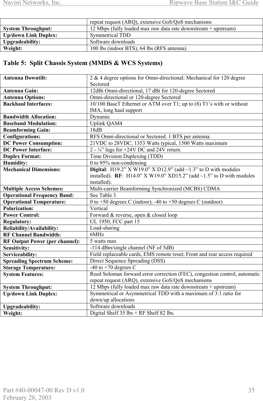
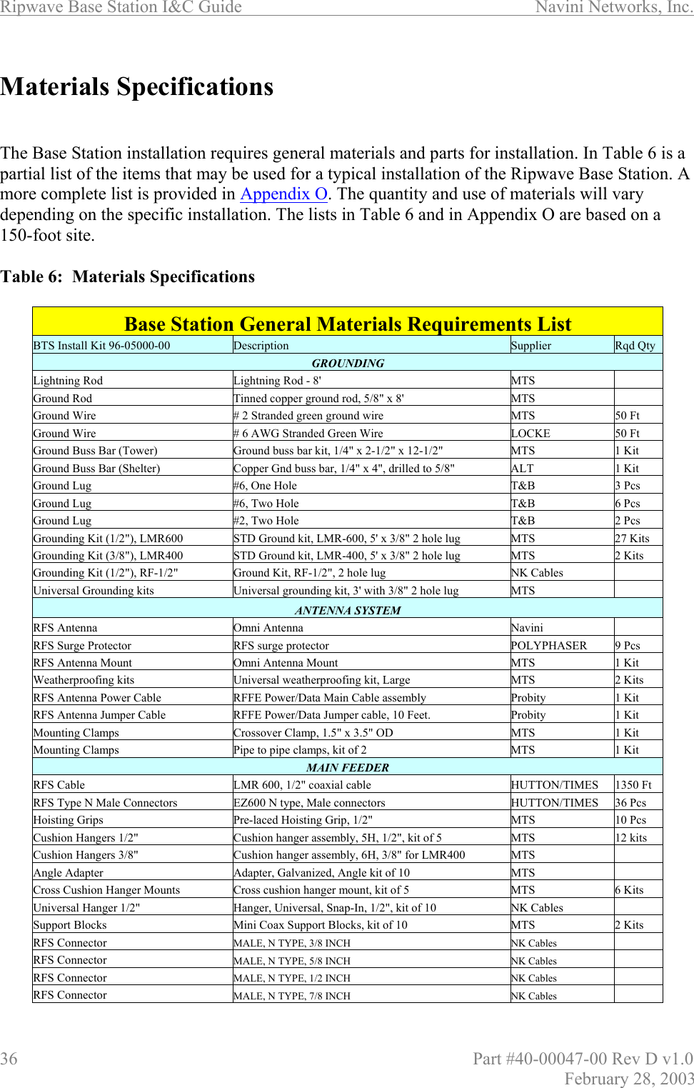
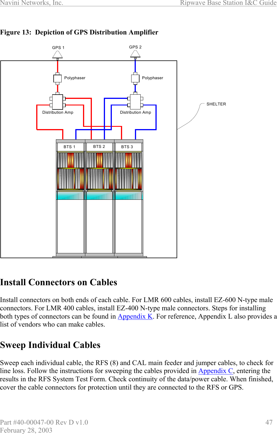
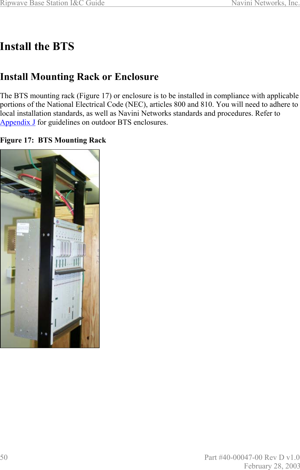
![Navini Networks, Inc. Ripwave Base Station I&C Guide Part #40-00047-00 Rev D v1.0 45 February 28, 2003 Install Cables All cable connections are made using standard RF coaxial cable. The Navini Networks standard for cable connections from the GPS to the BTS is LMR 400, 3/8-inch coaxial cable. Other types of cable that are comparable may be used. Using Tables 7 and 8, determine the size and type of cable to be used in the installation of the Base Station. Table 7: Active & Passive RFS Loss / Operating Parameters PA Max Output Power [dBm] BTS Max Output power with *Filter [dBm] CAL Cable Min Loss CAL Cable Max Loss RF Cable Min Loss [dB] Active RFS Loss Typ [dB] Passive RFS Loss Typ [dB] TX Pwr to Ant Min [dBm] TX Pwr to Ant Max [dBm] RX Power to Ant Min [dBm] RX Power to Ant Max [dBm] Notes 2.3 +38 +37 3.0 6.0 0 3.2 1.7 20 35 -95 -75 2.4 +37 N/A 4.0 9.5 0 3.2 1.7 10 25 -85 -65 -05 SYN 2.4 +37 N/A 3.0 4.5 0 3.2 1.7 18 30 -95 -70 -01 SYN 2.5 +39 +38 3.0 6.0 0 3.2 1.7 20 35 -95 -75 2.6 EFGH +39 +38 3.0 6.0 0 3.2 1.7 20 35 -95 -75 2.6 EF +37 +35 3.0 4.5 0 3.2 1.7 20 35 -95 -75 -05 SYN * Channel filter for 2.5/2.6 or Block Filter for 2.3 has 1.0 +/- 0.2 dB Insertion Loss * Channel filter for 2.6 EF Combo is 1.8 +/- 0.2 dB including cable to backplane. Table 8: Cable Attenuation in dB per 100 Feet Cable Type 2 ¼″ LDF 12-50 1 5/8″ LDF 7-50A LMR 1700 1 ¼″ LDF 6-50A LMR 1200 7/8″ LDF 5-50A LMR 900 5/8″ LDF 4.5-50A ½ ″ LDF 4-50A LMR 600 ½ ″ Super flex FSJ 4-50B LMR 500 3/8″ LDF 2-50A LMR 400 Frequency/Size 2.350 1.980 1.670 1.550 1.200 1.090 0.870 0.865 0.630 0.590 0.520 0.500 0.440 0.405 2000 MHz 0.994 1.11 1.5 1.42 1.99 1.82 2.64 2.27 3.25 3.9 5.09 4.84 5.17 6 2400 MHz N/A 1.24 1.7 1.5 2.2 2.02 2.9 2.52 3.63 4.3 5.67 5.4 5.67 6.6 2500 MHz N/A 1.27 1.71 1.53 2.26 2.07 3 2.58 3.70 4.42 5.8 5.48 5.91 6.8 2600 MHz N/A 1.3 1.8 1.57 2.3 2.12 3.1 2.64 3.78 4.5 5.94 5.6 5.91 6.9 Weight lbs/ft 1.22 0.82 0.74 0.63 0.45 0.33 0.27 0.15 0.15 0.13 0.14 0.1 0.08 0.07 Bend Radius inches 24 20 13.5 15 6.5 10 3 8 5 1.5 3 1.25 3.75 1](https://usermanual.wiki/Cisco-Systems/BTS-TP1.User-Manual-Section-1/User-Guide-369728-Page-45.png)