Cisco Systems 1805 Installation Manual 1805_comp.mif
2015-01-05
: Cisco-Systems Cisco-Systems-1805-Installation-Manual-202571 cisco-systems-1805-installation-manual-202571 cisco-systems pdf
Open the PDF directly: View PDF ![]() .
.
Page Count: 12
CHAPTER
8-1
Cisco 1805 DOCSIS Cable Router Hardware Installation Guide
OL-14661-01
8
Installing and Upgrading Internal Modules in
Cisco 1805 Cable Routers
This chapter describes how to install or upgrade modules that are located internally within the
Cisco 1805 DOCSIS cable router: memory modules and advanced integration modules (AIMs). You
need to remove the cover from the router to install or remove any of these items. The chapter contains
the following sections:
•Safety Warnings, page 8-1
•Modules Internal to the Cisco 1805 Cable Router, page 8-2
Note Before you install, operate, or service the system, read the Regulatory Compliance and Safety
Information for Cisco 1840 Routers for important safety information and translations of the warnings
that appear in this guide.
Safety Warnings
Warning
Before working on a system that has an on/off switch, turn OFF the power and unplug the power cord.
Statement 1
Warning
Before working on equipment that is connected to power lines, remove jewelry (including rings,
necklaces, and watches). Metal objects will heat up when connected to power and ground and can
cause serious burns or weld the metal object to the terminals.
Statement 43
Warning
During this procedure, wear grounding wrist straps to avoid ESD damage to the card. Do not directly
touch the backplane with your hand or any metal tool, or you could shock yourself.
Statement 94
Warning
Do not work on the system or connect or disconnect cables during periods of lightning activity.
Statement 1001

8-2
Cisco 1805 DOCSIS Cable Router Hardware Installation Guide
OL-14661-01
Chapter 8 Installing and Upgrading Internal Modules in Cisco 1805 Cable Routers
Modules Internal to the Cisco 1805 Cable Router
Warning
Read the installation instructions before you connect the system to its power source.
Statement 1004
Warning
Hazardous network voltages are present in WAN ports regardless of whether power to the router is
OFF or ON. To avoid electric shock, use caution when working near WAN ports. When detaching
cables, detach the end away from the router first.
Statement 1026
Modules Internal to the Cisco 1805 Cable Router
This section tells how to install a small-outline dual in-line memory module (SODIMM) and an
advanced integration module (AIM) in the Cisco 1805 cable router. It contains the following
subsections:
•Opening the Chassis, page 8-2
•Locating Modules, page 8-4
•Installing a SODIMM, page 8-5
•Installing an AIM, page 8-6
•Closing the Chassis, page 8-10
All the module replacement procedures in this section require removal of the chassis cover. Before you
perform any of the module replacement procedures, disconnect the power and remove the cover as
described in the “Opening the Chassis” section on page 8-2. After you complete the module replacement
procedures, install the chassis cover as described in the “Closing the Chassis” section on page 8-10.
Opening the Chassis
To open the chassis, follow these steps. You need a number one Phillips screw driver to complete this
procedure.
Step 1 Make sure that the router is turned off and is disconnected from AC power.
Step 2 Turn the router upside-down, and rest the top of the router on a flat surface.
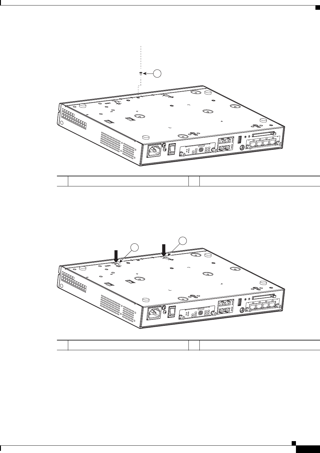
Step 3 Use the Phillips screwdriver to remove the screw that holds the top and bottom of the chassis together.
(See Figure 8-1.)
8-3
Cisco 1805 DOCSIS Cable Router Hardware Installation Guide
OL-14661-01
Chapter 8 Installing and Upgrading Internal Modules in Cisco 1805 Cable Routers
Modules Internal to the Cisco 1805 Cable Router
Figure 8-1 Removing the Chassis Screw
Step 4 Insert a flat-head screwdriver into the slots at the screwdriver pry points and rotate the screwdriver
90 degrees to disengage the top cover from the chassis. See Figure 8-2.
Figure 8-2 Screwdriver Pry Points
g
Step 5 Turn the router right side up (top up).
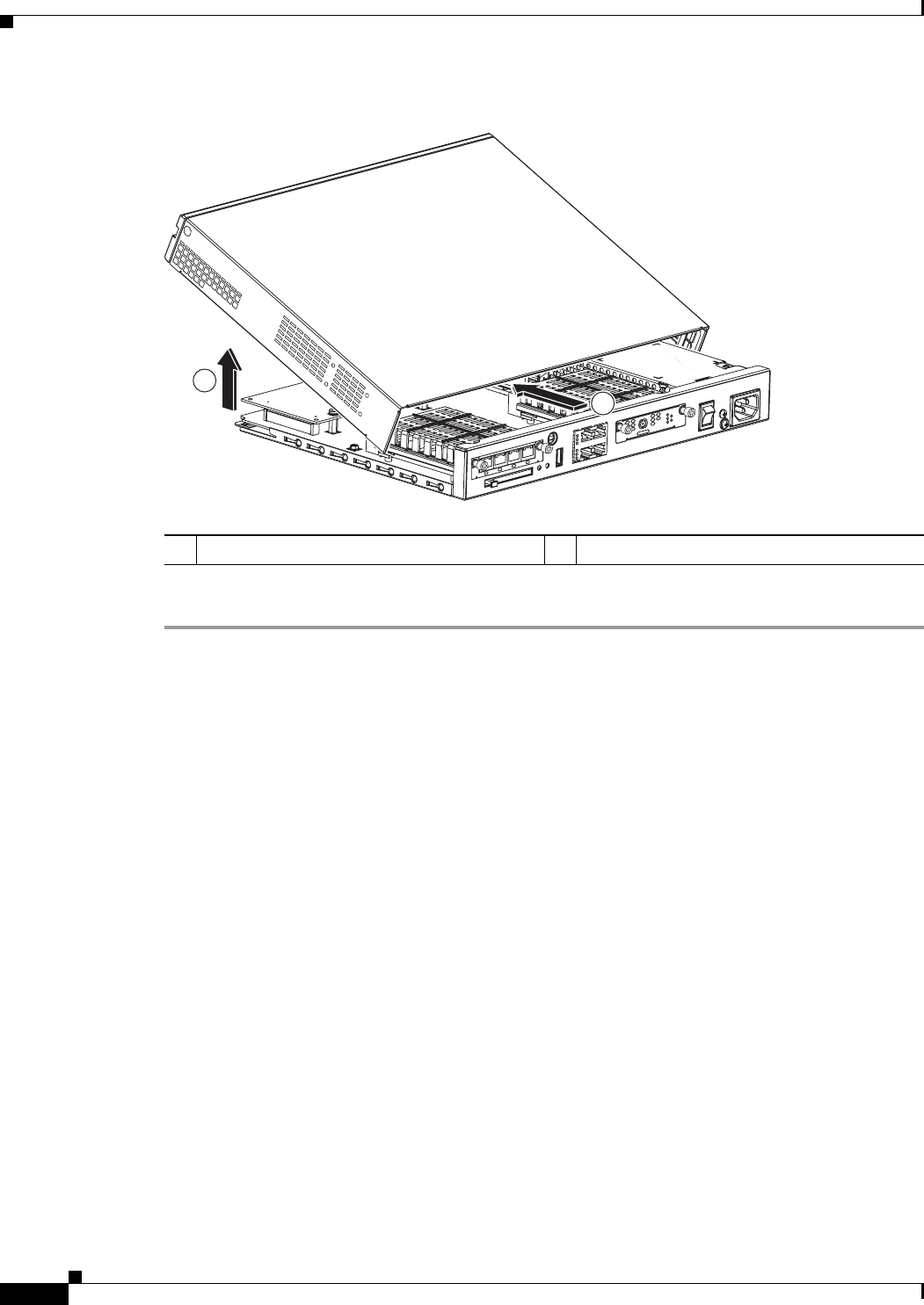
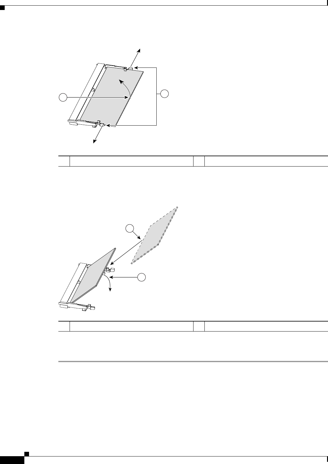
Step 6 Gently slide the top of the router (which is facing up toward you) away and up from the bottom of the
router (which is resting on the flat surface). See Figure 8-3.
1Router cover fastening screw
232509
1
LINK
US
ONLINE
HWIC-
CABLE-D-2
POWER
DS
CABLE
HWIC
4ESW
PWR3xLNKPWR2
xLNKPWR1
xLNKPWR0xLNK
1Screwdriver pry points
232513
1
1
LINK
US
ONLINE
HWIC-
CABLE-D-2
POWER
DS
CABLE
HWIC
4ESW
PWR 3x LNK PWR 2x LNK PWR 1x LNK PWR 0x LNK
8-4
Cisco 1805 DOCSIS Cable Router Hardware Installation Guide
OL-14661-01
Chapter 8 Installing and Upgrading Internal Modules in Cisco 1805 Cable Routers
Modules Internal to the Cisco 1805 Cable Router
Figure 8-3 Removing the Cover of the Cisco 1805 Router
Step 7 Place the router bottom on an antistatic mat, and begin installing the memory modules.
Locating Modules
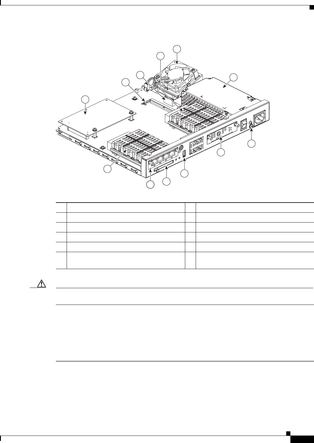
Figure 8-4 shows where the connector for the SODIMM or the AIM is located on the Cisco 1805 cable
router motherboard.
1Slide cover back from router chassis 2Rotate cover to remove from router chassis
232510
1
2
HWIC
4ESW
PWR 3x LNK PWR 2x LNK PWR 1x LNK PWR 0x LNK
LINK
US
ONLINE
HWIC-
CABLE-D-2
POWER
DS
CABLE
8-5
Cisco 1805 DOCSIS Cable Router Hardware Installation Guide
OL-14661-01
Chapter 8 Installing and Upgrading Internal Modules in Cisco 1805 Cable Routers
Modules Internal to the Cisco 1805 Cable Router
Figure 8-4 Cisco 1805 Cable Router (Internal View)
Caution Do not, under any circumstances, tamper with or attempt to remove the safety shields protecting the
high-speed WAN interface cards (HWIC) slots and connectors.
Installing a SODIMM
You can install a SODIMM to increase the amount of DRAM in the router.
To install a SODIMM on the router motherboard, follow these steps:
Step 1 Locate the SODIMM socket on the motherboard.
Step 2 Remove any existing SODIMM by gently pulling the spring-loaded clips on the end of the socket far
enough to clear the SODIMM, and gently pulling the SODIMM up and away from the socket. See
Figure 8-5.
1Ground screw 7AIM module
2Interface card slot 0 8SODIMM socket
3USB port 9Power supply connection
4CompactFlash memory card slot 10 System fan
5Interface card slot 1 11 Power supply
6Safety shields for WIC/HWIC slots and
connectors
10
7
1
3
4
5
6
8
911
15
6
232511
HWIC
4ESW
PWR3xLNKPWR2xLNKPWR1xLNKPWR0xLNK
LINK
US
ONLINE
HWIC-
CABLE-D-2
POWER
DS
CABLE
2
8-6
Cisco 1805 DOCSIS Cable Router Hardware Installation Guide
OL-14661-01
Chapter 8 Installing and Upgrading Internal Modules in Cisco 1805 Cable Routers
Modules Internal to the Cisco 1805 Cable Router
Figure 8-5 Removing a SODIMM
Step 3 Insert the SODIMM into the SODIMM socket, as shown in Figure 8-6.
Figure 8-6 Installing a SODIMM
Step 4 Firmly press the SODIMM into the socket until the spring-loaded clips on the socket snap over the end
of the SODIMM.
Installing an AIM
The Cisco 1805 cable router has the capability to support a single AIM module. To install an AIM, follow
the procedure given here.
1Spring-loaded clips 2SODIMM
103155
1
2
1SODIMM 2Insert and rotate into socket.
103154
1
2
8-7
Cisco 1805 DOCSIS Cable Router Hardware Installation Guide
OL-14661-01
Chapter 8 Installing and Upgrading Internal Modules in Cisco 1805 Cable Routers
Modules Internal to the Cisco 1805 Cable Router
Caution When you install an AIM, always wear an ESD-preventive wrist strap, and ensure that it makes good
contact with your skin. Connect the equipment end of the wrist strap to the metal part of the chassis.
Caution Handle AIMs by the edges only. AIMs are ESD-sensitive components and can be damaged by
mishandling.
Accessory Kit to Use
Some AIMs are provided with multiple accessory kits that contain different configurations of mounting
hardware. Mounting hardware for the Cisco 1805 cable router consists of two machine thread metal
standoffs, two machine thread metal screws, and one plastic standoff.
To install an AIM module on the Cisco 1805 cable router, use the hardware in mounting kit 69-1316-01.
Installation Procedure
To install the AIM, perform the following steps. You need a number 2 Phillips screwdriver or flat-head
screwdriver to complete this procedure.
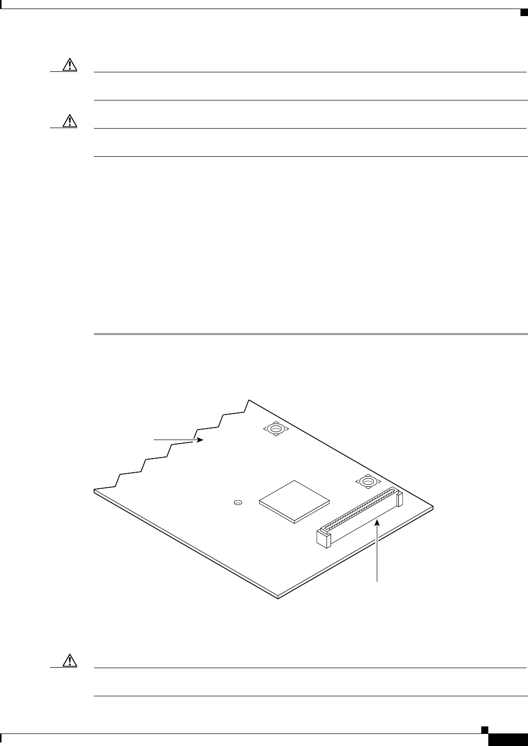
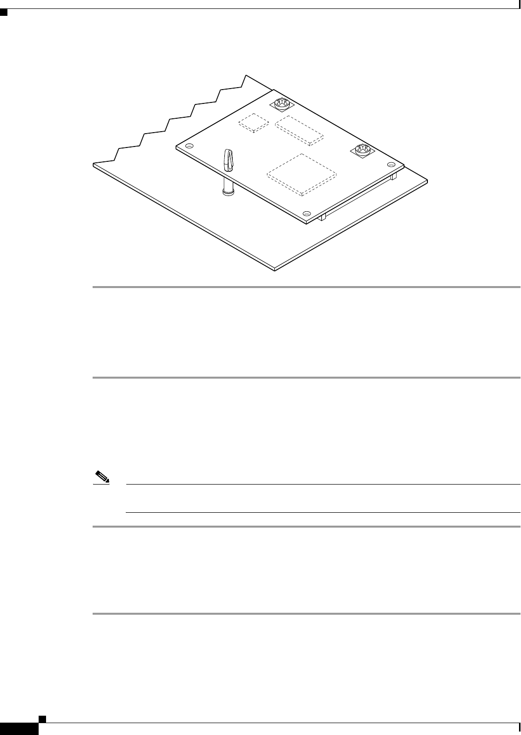
Step 1 Find the metal standoff attachment locations on the system board near the AIM connector, indicated by
a star pattern, as shown in Figure 8-7.
Figure 8-7 Location of Metal Standoff Attachment Locations
Step 2 Install the two metal standoffs from the accessory kit into the system board in the metal standoff
attachment locations. Use a 1/4-inch nut driver to tighten the standoffs. Locations for AIM standoffs are
denoted by a star pattern around the standoff mounting holes.
Caution Make sure that the standoffs are installed straight. Tighten them gently but firmly. The shoulder must be
seated tightly against the system board.
121107
System board
AIM connector
8-8
Cisco 1805 DOCSIS Cable Router Hardware Installation Guide
OL-14661-01
Chapter 8 Installing and Upgrading Internal Modules in Cisco 1805 Cable Routers
Modules Internal to the Cisco 1805 Cable Router
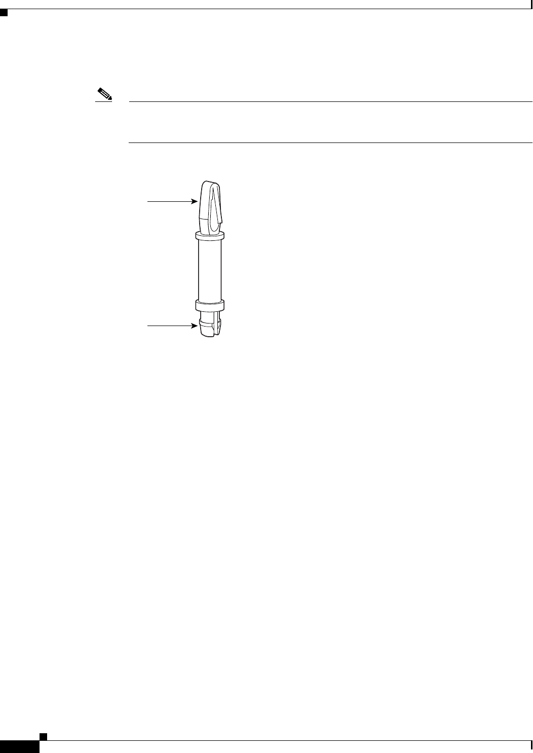
Step 3 Insert the plastic standoff (Figure 8-8) from the accessory kit into the hole in the system board. See
Figure 8-9. Press the standoff firmly into the system board to be sure that it is locked to the board.
Note The plastic standoff snaps into the system board. Be sure to insert the locking end of the standoff
into the system board. The locking end is the shortest end of the standoff. Figure 8-8 identifies
the locking end of the plastic standoff used with AIMs.
Figure 8-8 Plastic Standoff Orientation
82620
AIM end
Locking end
8-9
Cisco 1805 DOCSIS Cable Router Hardware Installation Guide
OL-14661-01
Chapter 8 Installing and Upgrading Internal Modules in Cisco 1805 Cable Routers
Modules Internal to the Cisco 1805 Cable Router
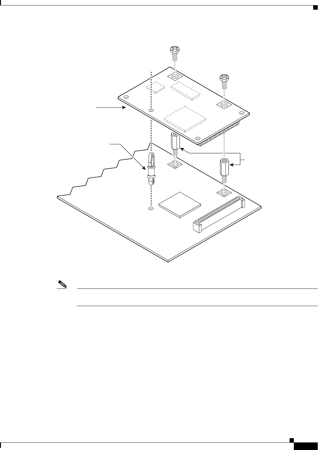
Figure 8-9 Connecting the AIM to the System Board
Step 4 Insert the connector on the AIM into the AIM connector on the system board. (See Figure 8-9.)
Note Be sure to press firmly on the AIM until the board seats onto the connector. The plastic standoff
must snap into the hole in the AIM board. (See Figure 8-9.)
Step 5 Insert the screws from the accessory kit through the AIM into the metal standoffs. (See Figure 8-9.)
Carefully tighten the screws with a Phillips screwdriver.
Step 6 Check that the AIM is installed correctly on the system board. (See Figure 8-10.)
121108
Metal standoffs
Snap-in
plastic
standoff
AIM
8-10
Cisco 1805 DOCSIS Cable Router Hardware Installation Guide
OL-14661-01
Chapter 8 Installing and Upgrading Internal Modules in Cisco 1805 Cable Routers
Modules Internal to the Cisco 1805 Cable Router
Figure 8-10 Correctly Installed AIM
Applying the AIM Label
The AIM label for the chassis might be in the AIM mounting kit, or it might be attached to the label on
the AIM card. Apply the chassis label as follows:
Step 1 If the chassis label is attached to the label on the AIM card, carefully tear off the chassis label at the
perforation. If the chassis label is in the AIM mounting kit, remove the label from the kit bag.
Step 2 Peel the chassis label from its backing.
Step 3 If there is a suitable space, apply the chassis label to the back of the chassis. If no suitable space is
available on the back of the chassis, apply the label to the top cover at the back edge. The label must be
visible with the chassis installed.
Note Do not apply the AIM label for the chassis to a blank cover plate, to any removable network
module or interface card, or over any holes, screws, chassis vents, or existing labels.
Closing the Chassis
To close the chassis, follow these steps:
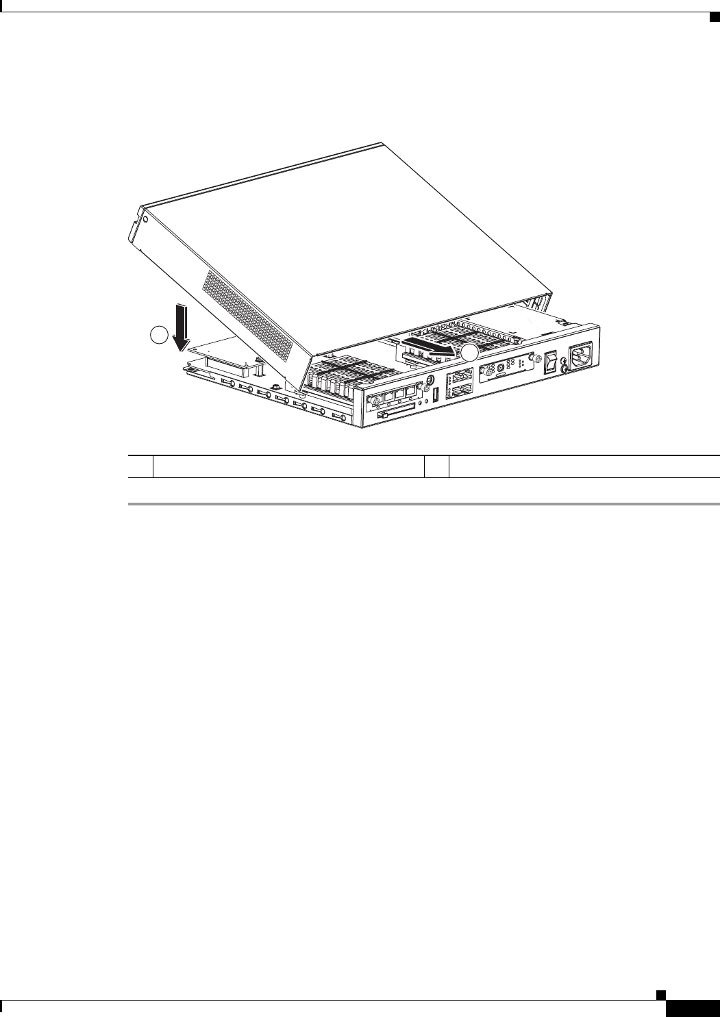
Step 1 Rotate the cover down onto the chassis. Then slide the cover back onto the bottom of the chassis. See
Figure 8-11.
Step 2 Push firmly to close.
Step 3 Turn the router upside-down.
58696
8-11
Cisco 1805 DOCSIS Cable Router Hardware Installation Guide
OL-14661-01
Chapter 8 Installing and Upgrading Internal Modules in Cisco 1805 Cable Routers
Modules Internal to the Cisco 1805 Cable Router
Step 4 Use a Phillips’ screwdriver to reinstall the screw that holds the cover to the chassis. See Figure 8-1.
Figure 8-11 Closing the Chassis
1Rotate cover onto router 2Slide cover onto router chassis
232512
2
1
HWIC
4ESW
PWR 3x LNK PWR 2x LNK PWR 1x LNK PWR 0x LNK
LINK
US
ONLINE
HWIC-
CABLE-D-2
POWER
DS
CABLE

8-12
Cisco 1805 DOCSIS Cable Router Hardware Installation Guide
OL-14661-01
Chapter 8 Installing and Upgrading Internal Modules in Cisco 1805 Cable Routers
Modules Internal to the Cisco 1805 Cable Router
