Cisco Systems 4000 Series Users Manual Overview.mif
4000 to the manual 53bc4139-5e0c-45fc-8638-b4ca7d49075e
2015-01-05
: Cisco-Systems Cisco-Systems-4000-Series-Users-Manual-202656 cisco-systems-4000-series-users-manual-202656 cisco-systems pdf
Open the PDF directly: View PDF ![]() .
.
Page Count: 18

CHAPTER
Overview of the Cisco 4000 Series Routers 1-1
1
Overview of the Cisco 4000
Series Routers
The Cisco 4000 series consists of the Cisco 4000-M, the Cisco 4500-M, and the
Cisco 4700-M. All models provide a configurable modular router platform using network
processor modules—individual modules that when installed in the router are ready for
external network connections. Performance is the key distinction between the
Cisco 4000-M, Cisco 4500-M, and Cisco 4700-M.
For maximum performance in the Cisco 4000 series, the Cisco 4700-M contains a
133-MHz RISC microprocessor, 16 to 64 MB main memory, and a 512-KB secondary
cache. The faster speed of the Cisco 4700-M allows higher throughput for high-speed
interfaces. The 512-KB secondary cache is useful for process switching applications such
as compression and encryption.
The Cisco 4500-M contains a 100-MHz RISC microprocessor and 8 to 32 MB of main
memory. The Cisco 4000-M contains a 40-MHz CISC microprocessor and 4 to 32 MB of
main memory.
All Cisco 4000 series routers provide flexibility, allowing network managers to easily
reconfigure the router when needs change.
The Cisco 4000 series routers support up to three network processor modules at a time. The
following network processor modules are available at the publication date of this guide:
•Single-port Fast Ethernet with 100BaseT and MII connectors provided for the port
•Single-port and dual-port Ethernet with 10BaseT and AUI connectors provided for each
port
•Six-port Ethernet with 10BaseT connectors provided for each port
•Dual-port and four-port synchronous serial supporting EIA/TIA-232, EIA/TIA-449,
V.35, X.21, NRZ/NRZI, DTE/DCE, or EIA-530 DTE interfaces on each port

1-2 Cisco 4000 Series Installation Guide
•Dual-port high-speed synchronous serial and 16-port low-speed
synchronous/asynchronous serial. The high-speed ports supports EIA/TIA-232,
EIA/TIA-449, V.35, X.21, NRZ/NRZI, DTE/DCE, or EIA-530 DTE interfaces. The
low-speed ports support EIA/TIA-232, V.35, or X.21 interfaces in DTE or DCE mode.
Each low-speed port can be individually configured for synchronous or asynchronous.
•Single-port HSSI
•Single-port and dual-port Token Ring
•Dual attachment single-mode FDDI
•Single attachment or dual attachment multimode FDDI
•Four-port or eight-port ISDN BRI
•Four-port balanced or unbalanced G.703/G.704
•Single-port channelized T1/ISDN PRI
•Single-port balanced or unbalanced channelized E1/ISDN PRI
•Single-port ATM with single-mode OC-3 and long-reach capability, multimode OC-3,
DS-3, or E3 interfaces
Note For information about modules released after publication of this guide, see the
configuration note packet shipped with your router.
Note EIA/TIA-232 and EIA-TIA-449 were known as recommended standards RS-232
and RS-449 before their acceptance as standards by the Electronics Industries Association
(EIA) and Telecommunications Industry Association (TIA)
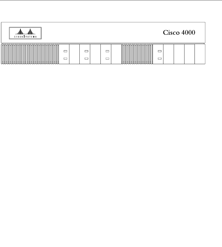
Figure 1-1 shows the front panel of a Cisco 4000 series router.
Figure 1-1 Cisco 4000 Series Chassis—Front Panel
Overview of the Cisco 4000 Series Routers 1-3
H3590
2
DATA
OK
3
DATA
OK
1
DATA
OK POWER
OK
SERIES

1-4 Cisco 4000 Series Installation Guide
Series Specifications
Series Specifications
Design specifications for the Cisco 4000 series are as follows:
•Modular router platform.
•Flash memory capability.
•User-upgradable network processor modules, shared memory, and processor local
memory.
•Hardware thermal alarm to warn of excessively high operating temperature.
•Can be rack-mounted in either a standard 19-inch rack or a telco rack.
•Can be mounted on a wall or placed on a desk or table.
•Support for up to three network processor modules at a time. Network processor
modules can be placed in any of the three available positions in almost any desired
combination. See the Cisco Product Catalog for complete configuration details.
The BRI four-port and eight-port network interface modules can not be used in the same
chassis with the channelized T1/ISDN PRI network interface module or the channelized
E1/ISDN PRI network interface module.
The Cisco 4000-M does not support Fast Ethernet, HSSI, 2T16S, ATM, or six-port Ethernet
network processor modules.The Cisco 4000-M can support only one FDDI network
processor module in combination with any two other types of network processor modules.
The Cisco 4500-M and Cisco 4700-M can support two FDDI network processor modules.
If you are only using one FDDI module, install it in the center slot for optimum heat
dissipation.
The Cisco 4500-M and Cisco 4700-M can support one ATM network processor module or
up to three six-port Ethernet network processor modules. The single-port Ethernet module
is not supported on the Cisco 4500-M or the Cisco 4700-M.
Note The Cisco 4500-M and Cisco 4700-M support all network processor modules except
the single-port Ethernet network processor module.

Overview of the Cisco 4000 Series Routers 1-5
Series Specifications
For complete configuration information, refer to the Cisco Product Catalog, which is
available on the Web at http://www.cisco.com.
Table 1-1 lists the network processor module interface options available for the Cisco 4000
series when this guide was printed. For current modules, see the configuration note packet
that shipped with your router.
Table 1-1 lists the specifications of the Cisco 4000 series routers.
Interface Options Port Options Part Numbers
Ethernet Single port, dual port, or six port NP-1E=, NP-2E=, NP-6E=
Fast Ethernet Single port NP-1FE=
Synchronous serial Dual port or four port NP-2T=, NP-4T=
Synchronous/asynchronous
serial1
1. Each low-speed port can be individually configured for synchronous or asynchronous.
Dual high-speed ports and
16 low-speed ports
NP-2T16S=
HSSI Single HSSI port NP-1HSSI=
Token Ring Dual port or single port NP-1RV2=, NP-2R=
Multimode FDDI Single attachment or dual attachment NP-1F-D-MM=,
NP-1F-S-M=
Single-mode FDDI Dual attachment NP-1F-D-SS=
BRI Four port or eight port NP-4B=, NP-8B=
G.703 Four port (balanced or unbalanced)2
2. For G.703 and G.704 connections, balanced or unbalanced ports must be matched with the corresponding
balanced or unbalanced cable.
NP-4GB=, NP-4GU=
Channelized T1/ISDN PRI Single channelized T1/PRI port NP-CT1=
Channelized E1/ISDN PRI Single channelized E1/PRI port NP-CE1=
ATM Single ATM port NP-1A-SM=,NP-1A-MM=
, NP-1A-DS3=,
NP-1A-E3=

1-6 Cisco 4000 Series Installation Guide
Series Specifications
Table 1-1 System Specifications
Software Compatibility
Network processor modules must be supported by the appropriate level of system software.
The minimum system software version for the original Cisco 4000 was Software
Release 9.1; for the Cisco 4000-M, Software Release 9.14; for the Cisco 4500, and
Cisco 4500-M, Cisco Internetwork Operating System (Cisco IOS) Release 10.2; for the
Cisco 4700-M, Cisco IOS Release 10.3(10). Table 1-2 lists the minimum system software
versions for network processor modules.
Description Specification
Dimensions (H x W x D) 3.4 x 17.6 x 17.7" (8.6 x 44.7 x 45 cm)
Weight 24 lb (10.9 kg) (including the chassis and network processor
modules)
Power 100–240 VAC, 50–60 Hz, 3.0–1.5A or 40–72 VDC, 5–2.8A
Wire gauge for DC-input
power connections
14 AWG1
1. AWG = American Wire Gauge
Network interface options Ethernet, serial, Token Ring, FDDI, BRI, G.703, channelized
T1/PRI, channelized E1/PRI, ATM
Serial interfaces EIA/TIA-232, EIA/TIA-449, V.35, X.21, NRZ/NRZI, DTE/DCE,
EIA-530 DTE
Console port EIA/TIA-232 DB-25 female connector
Auxiliary port EIA/TIA-232 DB-25 male connector
Nonoperating temperature – 40–185°F (– 40–85°C)
Operating humidity 5–95%, noncondensing
Operating temperature 32–104°F (0–40°C)
Regulatory compliance FCC Class A, FCC Part 68, Canadian DOC Class A, CS-03, UL
1950 2nd edition, CAN/CSA 950-M93, EN60950 with
Amendments 1 and 2, AN/NZS 3260, NOM 019
Additional regulatory compliance is in the Cisco 4000 Series Public
Network Certification document that shipped with your router.)

Overview of the Cisco 4000 Series Routers 1-7
Series Specifications
Table 1-2 Minimum Software Release Version
Note The Cisco 4000 can no longer be ordered, but Cisco IOS Releases 10.0, 10.2, and
10.3 are supported on installed Cisco 4000 routers. The Cisco 4500 can no longer be
ordered, but Cisco IOS Releases 10.1, 10.2, and 10.3 are supported on installed Cisco 4500
routers. The Cisco 4700 can no longer be ordered, but Cisco IOS Release 10.3 is supported
on installed Cisco 4700 routers.
Network Processor Module Type Minimum Software Release Version
Multimode FDDI Software Release 9.14(1)
Fast Ethernet Cisco IOS Release 11.1(5) or 11.2(2)P
Dual Ethernet Software Release 9.14(2)
Six-port Ethernet Cisco IOS Release 10.3(6)
Single-mode FDDI Software Release 9.14(3)
Dual and Version 2 Token Ring Software Release 9.14(5)
Four-port serial Software Release 9.14(6)
2T16S-RS232 and 2T16S-V.35 Cisco IOS Release 11.2(3)P for
synchronous operation
Cisco IOS Release 11.2(4)P for
asynchronous operation
2T16S-X.21 Cisco IOS Release 11.2(5)P
HSSI Cisco IOS Release 11.2(5)P
ISDN BRI Cisco IOS Release 10.2
G.703 Cisco IOS Release 10.2(7)
Channelized T1/ISDN PRI Cisco IOS Release 10.3(4)
Channelized E1/ISDN PRI Cisco IOS Release 10.3(4)
ATM OC-3C Cisco IOS Release 10.3(4)
ATM DS-3 and E3 Cisco IOS Release 11.0(5)


Overview of the Cisco 4000 Series Routers 1-9
Memory Systems
Table 1-3 Cisco 4000 Series Processor and Memory Specifications
Memory Systems
The Cisco 4000 series memory systems (see Figure 1-2) have the following functions:
•Main memory—Stores the running configuration and routing tables. The Cisco IOS
software executes from main memory.
•Shared memory—Used for packet buffering by the router’s network interfaces.
•Flash memory—Stores the operating system software image. In the Cisco 4500-M and
4700-M, the Flash memory also stores the boot helper software.
•NVRAM—Stores the system configuration file and the virtual configuration register.
•Boot EPROM—In the Cisco 4000-M, erasable programmable read-only memory
(EPROM)-based memory stores the boot helper—a subset of the Cisco IOS
software—and the ROM monitor. In the Cisco 4500-M and Cisco 4700-M, only the
ROM monitor is EPROM based. The boot helper image allows you to boot the router
Description Cisco 4000-M Cisco 4500-M Cisco 4700-M
Processor 40-MHz Motorola
68EC030
100-MHz IDT Orion
RISC1
1. The Orion microprocessor is based on the MIPS R4400 and is pin-compatible.
133-MHz IDT Orion
RISC
Main memory
(DRAM)2
2. DRAM = dynamic random-access memory.
4, 8, 16, or 32 MB 8, 16, or 32 MB 16, 32, or 64 MB
Secondary cache
memory
None None 512 KB
Shared memory
(DRAM)
4 or 16 MB 4, 8, or 16 MB 4, 8, or 16 MB
Flash memory 4 or 8 MB 4, 8, 16, 32, or 64 MB 4, 8, 16, 32, or 64 MB
NVRAM3
3. NVRAM = nonvolatile random-access memory.
128 KB 128 KB 128 KB
Boot ROM 128 KB–8 MB 128–512 KB 128–512 KB
Boot Flash Not available 4–16 MB 4–16 MB

1-10 Cisco 4000 Series Installation Guide
Memory Systems
when Flash memory does not contain a valid system image. In the Cisco 4500-M and
4700-M, the ROM monitor allows you to boot a system image from Flash memory if a
boot helper image is not present in boot Flash memory.
The differences between the memory systems in the Cisco 4000 series allows enhanced
software upgradability in the Cisco 4500-M and Cisco 4700-M.
Note See the appendixes “Cisco 4000 Series Virtual Configuration Register,”
“Cisco 4000-M ROM Monitor,” and “Cisco 4500-M and Cisco 4700-M ROM Monitor”
for more information on the ROM Monitor.
Figure 1-2 Cisco 4000 Series Memory Systems and Software Images
Cisco 4000 and Cisco 4000-M
EPROM-based Flash-memory based
Boot helper
(xboot)
ROM monitor
Cisco IOS
Cisco 4500, Cisco 4500-M, Cisco 4700, and Cisco 4700-M
EPROM-based Flash-memory based
ROM monitor Boot helper
(xboot)
H3537
Cisco IOS

Overview of the Cisco 4000 Series Routers 1-11
Memory Systems
Memory Requirements in the Cisco 4000 Series
Each module in the Cisco 4000 series can change memory configurations to accommodate
internetworking demands. The memory requirements are affected by the following factors:
•The number of Cisco IOS software images a system stores can be increase by adding
Flash memory.
•Network expansion, the use of additional protocols or Cisco IOS services, or newer
Cisco IOS releases may require additional main memory
•I/O performance or more physical or virtual interfaces may require additional shared
memory.
Shared Memory Requirements
The standard configuration for shared memory is 4 MB for the Cisco 4000 series. 4 MB of
memory is enough for most configurations with fewer than 24 physical or virtual interfaces.
Routers with multiple ISDN BRI network processor modules or with 24 or more physical
and virtual interfaces require 8 to 16 MB of shared memory.
Note The types and numbers of network processor modules installed in a system does not
affect main or flash memory requirements.

1-12 Cisco 4000 Series Installation Guide
Memory Systems
Table 1-4 Cisco 4000-M Shared Memory Requirements
Table 1-5 Cisco 4500-M and Cisco 4700-M Shared Memory Requirements
Network Processor Module
Per-Module Shared Memory
Requirements
Single-port Ethernet 0.1 MB
Dual-port Ethernet and dual-port
serial
0.2 MB
Dual-port Token Ring, four-port
serial, and G.703/G.704 serial
0.4 MB
Eight-port BRI, CT1/PRI, and
CE1/PRI
1.0 MB
FDDI 2.0 MB
Network Processor Module
Per-Module Shared
Memory Requirements
Dual-port Ethernet and dual-port serial 0.4 MB
Single-port Fast Ethernet 1.7 MB
Dual-port Token Ring, four-port serial, and G.703/G.704 serial 0.6 MB
Six-port Ethernet, Eight-port BRI, CT1/PRI, and CE1/PRI 1.2 MB
ATM and one FDDI1
1. FDDI modules are an exception in that two FDDI modules do not require double the shared memory of one FDDI
module.
2.0 MB
Two FDDI2
2. FDDI modules are an exception in that two FDDI modules do not require double the shared memory of one FDDI
module.
3.0 MB
Dual-port high-speed synchronous serial and 16-port
low-speed synchronous serial
0.6 MB
HSSI 1.0 MB

Overview of the Cisco 4000 Series Routers 1-13
Memory Systems
Note For more information, see product bulletin number 419, “Memory Options for
Cisco 4000 Series,” on the Web at http://www.cisco.com. This bulletin contains
information such as minimum memory requirements for each Cisco IOS image, current
shared memory requirements, and sample configurations.
Main Memory Requirements
The amount of main memory required by a Cisco 4000 series router is affected by the size
of the network and by the access list configurations. However, it is difficult to quantify the
exact main memory requirements based only on network size. Use the following guidelines
to determine approximate main memory requirements.
Note If your memory requirements fall near the upper end of one of the available main
memory options, consider installing the next larger memory option to allow for network
growth.
Main memory requirement guidelines for Cisco 4000 series routers are as follows:
•The 4 MB of main memory standard in the Cisco 4000-M will only suffice on routers
with knowledge of very small networks and which run very few protocols.
•The 8 MB of main memory standard in the Cisco 4500-M and the 16 MB of main
memory standard in the Cisco 4700-M generally suffices on routers running Cisco IOS
Release 10.2.
•16 MB of main memory, optional in the Cisco 4500-M and standard in the Cisco
4700-M, generally suffices on routers using Cisco IOS Release 10.3 or later.
•The 64 MB main memory option for the Cisco 4700-M is recommended for routers
using Border Gateway Protocol (BGP).

1-14 Cisco 4000 Series Installation Guide
Cisco RPS Support
Cisco RPS Support
The Cisco 4000-M, 4500-M, or 4700-M router now supports connection to the Cisco
Redundant Power System (RPS). The router supports an RPS in two ways:
•The chassis ships with an RPS adapter plate installed by the factory
•The user installs an RPS adapter plate at the site
For more information, refer to the Cisco RPS Hardware Installation Guide and Installing
the Cisco RPS Adapter Plate in Cisco 4000 Routers. This section provides an overview of
the Cisco RPS and describes basic features.
Figure 1-3 shows the front panel of the Cisco RPS, and Figure 1-4 shows the rear panel.
Figure 1-3 Cisco RPS Front Panel
Figure 1-4 Cisco RPS Rear Panel
H9588
DC STATUS
12
34
FAN
TEMP
H9589
AC INPUT 1
100-200 V~ 50/60 Hz
10-5 A 1000 W
AC INPUT 2
100-200 V~ 50/60 Hz
10-5 A 1000 W
DC OUTPUT 1 DC OUTPUT 2 DC OUTPUT 3 DC OUTPUT 4
Overview of the Cisco 4000 Series Routers 1-15
Cisco RPS Support
Caution Use the Cisco RPS (model PWR600-AC-RPS) only to power the external device.
Seul le système d’alimentation redondant Cisco (RPS modèle PWR600-AC-RPS) doit
servir à alimenter le dispositif externe.
Das externe Gerät darf nur mit einer redundanten Stromversorgung von Cisco, Modell
PWR600-AC-RPS, betrieben werden.
Para alimentar el dispositivo externo, usar exclusivamente el sistema de alimentación
redundante (redundant power system = RPS) Cisco, modelo PWR600-AC-RPS.
Overview
The Cisco RPS provides power system redundancy to external devices (such as routers,
switches, or hubs). The system includes two fully redundant AC input power modules and
four DC output power modules for connection to external devices. The Cisco RPS supports
the following power source configurations: quasi-redundant and fully redundant.
Quasi-Redundant Power
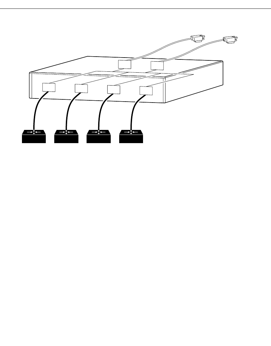
The Cisco RPS can provide a quasi-redundant power source for up to four external devices
that use 150W or less each. You can use a one-to-one cable (one connector at each end of
the cable) to connect up to four external devices to the four DC output power modules, as
shown in Figure 1-5. When using one-to-one cables, the power source is quasi-redundant
because there are two AC input power modules for the Cisco RPS and one DC power output
module for each external device. The AC input to the Cisco RPS is fully redundant, but the
DC output to the external devices is not.
Figure 1-5 Quasi-Redundant Configuration
1-16 Cisco 4000 Series Installation Guide
Cisco RPS Support
Fully Redundant Power
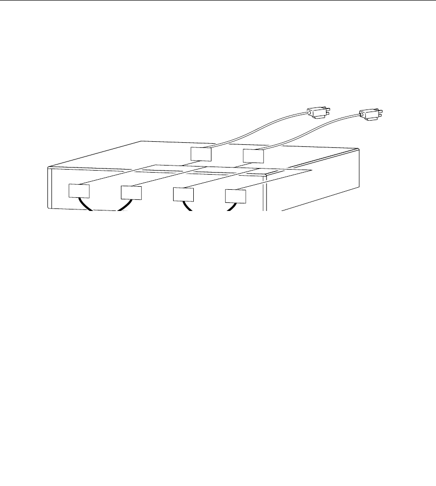
The Cisco RPS can provide a fully redundant power source for up to two Cisco 4000 series
routers. You can use a two-to-one cable to connect up to two external devices to the four
DC output power modules on the rear panel of the Cisco RPS, as shown in Figure 1-6. The
two-to-one cable is a Y-shaped cable with two connectors at one end of the cable and one
connector at the other end. Two connectors at one end of the Y-shaped cable connect to two
DC output power modules. The other end of the cable connects to one external device.
When using two-to-one cables, the power source is fully redundant because there are two
AC input modules and two DC output power modules connected to each external device. If
any power module fails, there is a full backup.
Figure 1-6 Fully Redundant Configuration
External devices
150W or less
DC output
AC input
DC DC
AC AC
DC DC
Cisco RPS
NM3998
Overview of the Cisco 4000 Series Routers 1-17
Cisco RPS Support
RPS Features
The following features are standard:
•Two AC input power cords
•Two fully redundant AC input power modules
•Four 150W DC output power modules
•Four one-to-one cables (PWR600-AC-RPS-CAB)
•Rack-mountable chassis (two rack units in height, 19-inch rack-mount brackets
included)
•Redundant cooling
•LEDs for the AC and DC status, fans, and temperature
AC input
DC DC DC DC
Cisco RPS
NM3999
AC AC

1-18 Cisco 4000 Series Installation Guide
Cisco RPS Support
