Cisco Systems 545 Serial Installation And Upgrade Guide 2ugwv55i
545 Serial to the manual 17dc1419-3a76-42fe-adab-b7324978817c
2015-01-05
: Cisco-Systems Cisco-Systems-545-Serial-Installation-And-Upgrade-Guide-202332 cisco-systems-545-serial-installation-and-upgrade-guide-202332 cisco-systems pdf
Open the PDF directly: View PDF ![]() .
.
Page Count: 74
- Installation and Upgrade Guide for Cisco Unified Videoconferencing 3545 PRI Gateway and 3545 Serial Gateway Release 5.5
- Contents
- Functionality
- Installing the Cisco Unified Videoconferencing 3545 Gateway
- Physical Description
- Preparing for Installation
- Verifying the Package Contents
- Mounting the Cisco Unified Videoconferencing 3545 Chassis in a 19-inch Rack
- Installing the Gateway
- Initial Gateway Configuration
- Connecting the Gateway to the Network
- Connecting PRI Lines to the Gateway
- Connecting Serial Lines to the Gateway
- Serial Gateway Cable Connections and Pin-outs
- Connecting the Gateway to a Power Source
- Accessing the Gateway Administrator Interface
- Registering the Online Help
- Using the Cisco Software Upgrade Utility
- Cable Connections and Pin-outs
- Technical Specifications
- Safety
- Sicherheit
- Seguridad
- Securite
- Compliance and Certifications
- Index

Americas Headquarters
Cisco Systems, Inc.
170 West Tasman Drive
San Jose, CA 95134-1706
USA
http://www.cisco.com
Tel: 408 526-4000
800 553-NETS (6387)
Fax: 408 527-0883
Installation and Upgrade Guide for
Cisco Unified Videoconferencing 3545
PRI Gateway and 3545 Serial Gateway
Release 5.5
January 2008
Customer Order Number:
Text Part Number: OL-14912-01

THE SPECIFICATIONS AND INFORMATION REGARDING THE PRODUCTS IN THIS MANUAL ARE SUBJECT TO CHANGE WITHOUT NOTICE. ALL
STATEMENTS, INFORMATION, AND RECOMMENDATIONS IN THIS MANUAL ARE BELIEVED TO BE ACCURATE BUT ARE PRESENTED WITHOUT
WARRANTY OF ANY KIND, EXPRESS OR IMPLIED. USERS MUST TAKE FULL RESPONSIBILITY FOR THEIR APPLICATION OF ANY PRODUCTS.
THE SOFTWARE LICENSE AND LIMITED WARRANTY FOR THE ACCOMPANYING PRODUCT ARE SET FORTH IN THE INFORMATION PACKET THAT
SHIPPED WITH THE PRODUCT AND ARE INCORPORATED HEREIN BY THIS REFERENCE. IF YOU ARE UNABLE TO LOCATE THE SOFTWARE LICENSE
OR LIMITED WARRANTY, CONTACT YOUR CISCO REPRESENTATIVE FOR A COPY.
The Cisco implementation of TCP header compression is an adaptation of a program developed by the University of California, Berkeley (UCB) as part of UCB’s public
domain version of the UNIX operating system. All rights reserved. Copyright © 1981, Regents of the University of California.
NOTWITHSTANDING ANY OTHER WARRANTY HEREIN, ALL DOCUMENT FILES AND SOFTWARE OF THESE SUPPLIERS ARE PROVIDED “AS IS” WITH
ALL FAULTS. CISCO AND THE ABOVE-NAMED SUPPLIERS DISCLAIM ALL WARRANTIES, EXPRESSED OR IMPLIED, INCLUDING, WITHOUT
LIMITATION, THOSE OF MERCHANTABILITY, FITNESS FOR A PARTICULAR PURPOSE AND NONINFRINGEMENT OR ARISING FROM A COURSE OF
DEALING, USAGE, OR TRADE PRACTICE.
IN NO EVENT SHALL CISCO OR ITS SUPPLIERS BE LIABLE FOR ANY INDIRECT, SPECIAL, CONSEQUENTIAL, OR INCIDENTAL DAMAGES, INCLUDING,
WITHOUT LIMITATION, LOST PROFITS OR LOSS OR DAMAGE TO DATA ARISING OUT OF THE USE OR INABILITY TO USE THIS MANUAL, EVEN IF CISCO
OR ITS SUPPLIERS HAVE BEEN ADVISED OF THE POSSIBILITY OF SUCH DAMAGES.
Any Internet Protocol (IP) addresses used in this document are not intended to be actual addresses. Any examples, command display output, and figures included in the
document are shown for illustrative purposes only. Any use of actual IP addresses in illustrative content is unintentional and coincidental.
Installation and Upgrade Guide for Cisco Unified Videoconferencing 3545 PRI Gateway and 3545 Serial Gateway Release 5.5
© 2008 Cisco Systems, Inc. All rights reserved.
CCVP, the Cisco logo, and the Cisco Square Bridge logo are trademarks of Cisco Systems, Inc.; Changing the Way We Work, Live, Play, and Learn is a service mark of Cisco Systems,
Inc.; and Access Registrar, Aironet, BPX, Catalyst, CCDA, CCDP, CCIE, CCIP, CCNA, CCNP, CCSP, Cisco, the Cisco Certified Internetwork Expert logo, Cisco IOS, Cisco
Press,
Cisco Systems, Cisco Systems Capital, the Cisco Systems logo, Cisco Unity, Enterprise/Solver, EtherChannel, EtherFast, EtherSwitch, Fast Step, Follow Me Browsing,
FormShare, GigaDrive, HomeLink, Internet Quotient, IOS, iPhone, IP/TV, iQ Expertise, the iQ logo, iQ Net Readiness Scorecard, iQuick Study, LightStream, Linksys,
MeetingPlace, MGX, Networking Academy, Network Registrar, PIX, ProConnect, ScriptShare, SMARTnet, StackWise, The Fastest Way to Increase Your Internet Quotient, and
TransPath are registered trademarks of Cisco Systems, Inc. and/or its affiliates in the United States and certain other countries.
All other trademarks mentioned in this document or Website are the property of their respective owners. The use of the word partner does not imply a partnership relationship
between Cisco and any other company. (0709R)

iii
Installation and Upgrade Guide for Cisco Unified Videoconferencing 3545 PRI Gateway and 3545 Serial Gateway Release 5.5
OL-14912-01
CONTENTS
CHAPTER
1Functionality 1-1
About Cisco Unified Videoconferencing 3545 Gateway Products 1-1
About the Cisco Unified Videoconferencing 3545 PRI Gateway 1-1
About the Cisco Unified Videoconferencing 3545 Serial Gateway 1-1
About Gateway Features 1-2
About Cisco Unified Videoconferencing 3545 Gateway Applications and Topologies 1-6
About Multimedia Conferencing 1-7
About Point-to-Point Conferencing 1-8
About Multipoint Conferencing 1-8
About Gateway IP Network Connections 1-9
About Gateway ISDN Network Connections 1-9
About Gateway Encryption 1-11
About Conferencing via Leased Lines 1-12
About IP-to-Legacy MCU Conferencing 1-12
About Cisco Unified Videoconferencing 3545 Gateway Functionality 1-13
About PRI Gateway Call Handling Capacity 1-13
About Gateway Call Bandwidth Overhead 1-13
Resource Allocation across E1/T1 Lines 1-14
About Peer-to-Peer Connectivity 1-14
CHAPTER
2Installing the Cisco Unified Videoconferencing 3545 Gateway 2-1
Physical Description 2-1
Gateway Module 2-1
Cisco Unified Videoconferencing 3545 PRI Gateway RTM 2-2
Cisco Unified Videoconferencing 3545 Serial Gateway RTM 2-3
Preparing for Installation 2-3
Verifying the Package Contents 2-4
Mounting the Cisco Unified Videoconferencing 3545 Chassis in a 19-inch Rack 2-5
Installing the Gateway 2-6
Installing the RTM Module 2-7
Installing the Gateway Module 2-8
Removing a Module 2-9
Initial Gateway Configuration 2-10
Connecting to a PC 2-10

Contents
iv
Installation and Upgrade Guide for Cisco Unified Videoconferencing 3545 PRI Gateway and 3545 Serial Gateway Release 5.5
OL-14912-01
Setting the IP Address 2-11
Changing the Configuration Tool Login Password 2-12
Upgrading Gateway Software 2-13
Connecting the Gateway to the Network 2-14
Connecting PRI Lines to the Gateway 2-14
Connecting Serial Lines to the Gateway 2-14
Serial Gateway Cable Connections and Pin-outs 2-15
Physical Description of DTE Cables 2-15
Physical Description of DCE Cables 2-19
Data Interface Cable Pin-out Configurations 2-21
Data Interface Pin Layouts 2-22
DB-25 Connector 2-24
Signaling Interface Cable Pin-out Configuration 2-25
Signaling Interface Pin Layout 2-26
Connecting the Gateway to a Power Source 2-27
Accessing the Gateway Administrator Interface 2-27
Registering the Online Help 2-28
Netscape Navigator Users 2-28
CHAPTER
3Using the Cisco Software Upgrade Utility 3-1
Introduction 3-1
Launching the Cisco Software Upgrade Utility 3-1
Upgrading Software 3-2
CHAPTER
4Cable Connections and Pin-outs 4-1
Unit RS-232 9-Pin Serial Port 4-1
9-Pin Serial Port Terminal Cable 4-2
RJ-45 8-Pin IP Network Port 4-2
Circuit Switch Network Port 4-3
ISDN Port 4-3
CHAPTER
5Technical Specifications 5-1
Technical Specifications Table 5-1
CHAPTER
6Safety 6-1
Electrical Safety 6-1
Grounding 6-1

Contents
v
Installation and Upgrade Guide for Cisco Unified Videoconferencing 3545 PRI Gateway and 3545 Serial Gateway Release 5.5
OL-14912-01
High Voltage 6-2
Power Supply 6-2
ESD Procedures 6-2
Sicherheit 6-3
Elektrische Sicherheit 6-3
Erdung 6-3
Hochspannung 6-3
Netzteil 6-3
ESD-Verfahren 6-4
Warnhinweise 6-4
Seguridad 6-5
Seguridad Electrica 6-5
Tierra 6-5
Alto Voltage 6-5
Abastecimiento de Electricidad 6-5
Procedimientos ESD 6-6
Securite 6-7
Securite Electrique 6-7
Mise a la Terre 6-7
Haute Tension 6-8
Alimentation Electrique 6-8
Prevention des Decharges Electrostatiques 6-8
CHAPTER
7Compliance and Certifications 7-1
Safety Compliance 7-1
EMC 7-2
FCC Part 15 Notice 7-2
Telecom 7-2
ACTA Customer Information 7-3
Canadian Department of Communications Notice 7-3
Environmental Compliance 7-4
I
NDEX

Contents
vi
Installation and Upgrade Guide for Cisco Unified Videoconferencing 3545 PRI Gateway and 3545 Serial Gateway Release 5.5
OL-14912-01

CHAPTER
1-1
Installation and Upgrade Guide for Cisco Unified Videoconferencing 3545 PRI Gateway and 3545 Serial Gateway Release 5.5
OL-14912-01
1
Functionality
This section describes the following topics:
•About Cisco Unified Videoconferencing 3545 Gateway Products, page 1-1
•About Gateway Features, page 1-2
•About Cisco Unified Videoconferencing 3545 Gateway Applications and Topologies, page 1-6
•About Cisco Unified Videoconferencing 3545 Gateway Functionality, page 1-13
About Cisco Unified Videoconferencing 3545 Gateway Products
Cisco Unified Videoconferencing 3545 Gateway series consists of the following products:
•Cisco Unified Videoconferencing 3545 PRI Gateway (see the “About the Cisco Unified
Videoconferencing 3545 PRI Gateway”)
•Cisco Unified Videoconferencing 3545 Serial Gateway (see the “About the Cisco Unified
Videoconferencing 3545 Serial Gateway”)
About the Cisco Unified Videoconferencing 3545 PRI Gateway
The Cisco Unified Videoconferencing 3545 PRI Gateway enables audio, video, and data communication
between H.320 endpoints that connect through ISDN, and H.323 endpoints that connect through a
packet-based network. For voice-over-IP, the gateway enables PSTN voice callers to connect from the
ISDN network to IP voice callers. The CISCO UNIFIED VIDEOCONFERENCING 3545 PRI
GATEWAY supports two PRI ISDN ports.
About the Cisco Unified Videoconferencing 3545 Serial Gateway
The Cisco Unified Videoconferencing 3545 Serial Gateway supports multimedia conferencing over IP
by translating between H.323 and serial protocols. With the help of a V.35 Adtran Imux, the gateway can
also translate between H.323 and H.320 protocols.
The gateway offers a serial leg for multimedia conferencing over IP by providing an interface for legacy
endpoints with serial interfaces, encryption/decryption devices, satellite networks and leased line
services.

1-2
Installation and Upgrade Guide for Cisco Unified Videoconferencing 3545 PRI Gateway and 3545 Serial Gateway Release 5.5
OL-14912-01
Chapter 1 Functionality
About Gateway Features
About Gateway Features
Table 1-1 lists the major features of the Cisco Unified Videoconferencing 3545 Gateway.
Table 1-1 Gateway Feature Summary
Feature Description
Interoperability The gateway provides a high degree of interoperability with other H.323
compliant gateways, gatekeepers, terminals, proxy, and Multipoint
Control Unit (MCU) products by being based on the H.320 standard and
H.323 protocol stack.
Web-based
management
The gateway features the gateway interface. This is a web interface used
to configure and monitor the gateway. You can view and modify all
aspects of the gateway configuration from a remote location using a
Java-enabled web browser.
SNMP management The gateway features Simple Network Management Protocol (SNMP)
management that supports all aspects of monitoring, diagnostics,
configuration, and trapping.
Diagnostics The gateway features front and rear panel LED indicators that display
status for the unit. You can also access remote diagnostics of the unit
through the gateway interface, Telnet, SNMP, or a serial port.
Network load
balancing
The gateway supports load balancing on the network by communicating
with a gatekeeper through H.323 RAI (Resource Available
Indication)/RAC (Resource Available Confirmation) messages.
T.120 data
collaboration
The gateway supports data transfers in calls between ISDN and IP by
using high speed T.120 in HMLP and VarMLP formats.
Quality of service
(QoS)
The gateway features configurable coding of media packets to achieve
QoS routing priority on the Internet Protocol (IP) network. The Type of
Service (ToS) bits of the IP datagram header can be configured for priority
level.
Dial plan The gateway supports a simplified dial plan for outbound dialing using a
single universal prefix. Using the dial plan, the gateway automatically
detects the capabilities received in the Setup message from the IP endpoint
and sets the same bit rate for the ISDN (or serial interface) side of the call.
Direct dialing and call
routing
The gateway dial plan supports the following direct dialing and call
routing facilities:
•Direct Inward Dialing (DID)
•Multiple Subscriber Network (MSN)
•Q.931 Sub-addressing Information Element
Cisco Unified Videoconferencing 3545 Serial Gateway supports DID in
DCE mode only.
•Internal and External Interactive Voice Response (IVR)
•TCS4
•Default extension

1-3
Installation and Upgrade Guide for Cisco Unified Videoconferencing 3545 PRI Gateway and 3545 Serial Gateway Release 5.5
OL-14912-01
Chapter 1 Functionality
About Gateway Features
Access control The gateway features password-controlled access to the gateway interface.
Up to ten different administrator access profiles can be defined for the
gateway.
DTMF translation The gateway supports translation between in-band Dual Tone
Multi-Frequency (DTMF) signals (on the ISDN side) and out-of-band
H.245 messages (on the IP side). DTMF translation occurs for voice and
video calls.
Dual video The gateway supports H.239 standards-based dual video and TANDBERG
DuoVideo technology. Dual video streams enable a screen to carry video
images from one source while simultaneously displaying images from a
second source.
Hot swap The gateway features hot swap functionality that you can use to remove
and replace gateway cards under power.
Conceal caller ID The gateway supports a conceal caller ID feature that instructs the
gatekeeper to conceal the identity of the calling endpoint on the IP or
ISDN network, whether the presentation restricted feature is enabled or
not.
H.323 fast start The gateway H.323 fast start feature enables endpoints to join a voice
conference in the gateway more quickly.
ISDN rollover
(available in Cisco
Unified
Videoconferencing
3545 PRI Gateway
only)
The gateway features ISDN rollover. In this feature, the gateway sends a
“busy out” channel request to the PSTN switch when the current PRI
connection is left with less than a predefined number of available B
channels. The PSTN switch “rolls over” to the next available gateway.
Network Specific
Facility (available in
Cisco Unified
Videoconferencing
3545 PRI Gateway
only)
The gateway provides support for Network Specific Facility Information
Elements (NSF IEs) which enable system administrators to specify to
service providers the equipment, service, or network through which they
want a call routed.
ISDN connection
failure
The gateway responds to ISDN connection failure events, by unregistering
from its gatekeeper. The gatekeeper is forced to send new IP-to-ISDN
calls through a different gateway, thus ensuring high call completion rates.
The gateway re-registers to the gatekeeper when the ISDN connection is
restored.
Downspeeding The gateway features downspeeding functionality. In the downspeeding
feature, the gateway attempts to reconnect a disconnected video call either
at a lower bandwidth or as a voice call. Downspeeding contributes to a
higher percentage of call completion on the network. The gateway
supports downspeeding at call setup and in mid-call.
Multiple trap server
support
The gateway supports up to three SNMP trap servers.
H.239 support The gateway supports the H.239 protocol in ISDN-to-IP calls and in
IP-to-ISDN calls.
Table 1-1 Gateway Feature Summary (continued)
Feature Description

1-4
Installation and Upgrade Guide for Cisco Unified Videoconferencing 3545 PRI Gateway and 3545 Serial Gateway Release 5.5
OL-14912-01
Chapter 1 Functionality
About Gateway Features
Table 1-2 lists features for specific Cisco gateways.
Encryption support The gateway supports H.235-compliant AES 128 encryption for calls over
IP networks, and H.233 and H.234-compliant AES 128 encryption for
calls over ISDN networks.
H.243 Conference
Control support
The gateway supports the H.243 protocol in ISDN-to-IP calls and in
IP-to-ISDN calls. The gateway identifies the protocol version that an IP
endpoint uses and sends H.239 capabilities only to those endpoints
working with protocol version 4.0 or later.
Peer-to-peer
connectivity
The gateway supports connectivity to the IP network through a gatekeeper,
or directly to a peer device such as Cisco Unified Communications
Manager.
IP network
connections
The gateway has one 10/100Base-T Ethernet IP port (on the front panel)
and connects to an IP segment through a direct connection to a network
switch.
Table 1-1 Gateway Feature Summary (continued)
Feature Description
Table 1-2 Cisco Gateway Feature Specifics
Feature Cisco Unified Videoconferencing
3545 PRI Gateway
Cisco Unified Videoconferencing
3545 Serial Gateway
Supported ports 2 PRI ISDN ports 4 serial ports
Supported video
conferencing protocols
H.320, H.323 (using Cisco Stack v4.0)
Supported audio codecs The term audio transcoded video calls refers to the process whereby an
audio stream in a multimedia call can be transcoded from one codec type to
another.
Basic and advanced audio coding supported codecs: G.711, G.722, G.722.1,
G.723.1, G.728
Audio Transcoding G.711 (ISDN) < > G.723.1 (IP) for
up to 60 voice channels.
Transcoding for the 4 supported
multimedia calls.
G.711 (IP) < > G.728 (ISDN) for up
to 20 audio transcoded video
channels.
The gateway automatically performs
A-Law G.711-to-µ-Law G.711
translation between the IP and ISDN
sides if needed.
Note When your Cisco unit
includes both a gateway and
a MCU, G.728 transcoding is
supported on the MCU only.
Supported video
protocols
H.261, H.263, H.263+ (Annexes F, J and N), H.263++ (Annex W), H.264

1-5
Installation and Upgrade Guide for Cisco Unified Videoconferencing 3545 PRI Gateway and 3545 Serial Gateway Release 5.5
OL-14912-01
Chapter 1 Functionality
About Gateway Features
Supported video
resolutions
VGA, XGA, SVGA, SIF, 4SIF, CIF, QCIF, 4CIF, 16CIF
Supported bandwidths
(Kbps)
56, 64, 112, 128, 168, 192, 224, 256,
280, 320, 336, 384, 448, 512, 672,
768, 1288, 1472, 1680 and 1920
56, 64, 112, 128, 168, 192, 224, 256,
280, 320, 336, 384, 448, 512, 672,
768, 1288, 1472 and 1920
Note Bandwidth rates of 256 Kbps and up support the G.722 audio codec.
Call handling
capabilities
For 1 x PRI T1 line:
23 ports (voice)
23 ports 1B (video and data)
11 ports 2B (video and data)
3 ports 6B (video and data)
For 2 x PRI T1 lines:
46 ports (voice)
30 ports 1B (video and data)
23 ports 2B (video and data)
7 ports 6B (video and data)
For 1 x PRI E1 line:
30 ports (voice)
30 ports 1B (video and data)
15 ports 2B (video and data)
5 ports 6B (video and data)
For 2 x PRI E1 lines:
60 ports (voice)
30 ports 1B/2B (video and data)
10 ports 6B (video and data)
1 call per serial connection, up to a
maximum bandwidth of 1920 Kbps
per port.
Line quality Supports line echo cancellation,
H.323 Fast Start and DTMF
detection for voice and video calls.
Supports line echo cancellation and
DTMF detection for voice calls.
IP network connection I10/100Base-T Ethernet IP UTP connection (on the front panel).
Serial control port
(DB-9) connection
RS-232 DTE 9-pin D-type connection on front panel for connection to a PC
terminal or an external modem.
Supported media
protocols
N/A V.35, RS-449, EIA-530, EIA-530A
Supported signaling
protocols
5ESS and 4ESS, DMS100, National
ISDN, Euro-ISDN, VN6 Dialing
(France), NTT (Japan), Hong Kong
Dialing (Hong Kong), Support for
Taiwan PRI system.
RS-366, Manual Control, Data
Triggered.
Table 1-2 Cisco Gateway Feature Specifics (continued)
Feature Cisco Unified Videoconferencing
3545 PRI Gateway
Cisco Unified Videoconferencing
3545 Serial Gateway

1-6
Installation and Upgrade Guide for Cisco Unified Videoconferencing 3545 PRI Gateway and 3545 Serial Gateway Release 5.5
OL-14912-01
Chapter 1 Functionality
About Cisco Unified Videoconferencing 3545 Gateway Applications and Topologies
About Cisco Unified Videoconferencing 3545 Gateway
Applications and Topologies
The Cisco Unified Videoconferencing 3545 Gateway supports multimedia conferencing by translating
between H.323 and H.320 protocols. Examples of network applications that use the gateway include:
•Multimedia conferencing (see the “About Multimedia Conferencing” section on page 1-7)
•Point-to-Point conferencing (see the “About Point-to-Point Conferencing” section on page 1-8)
•Multipoint conferencing (see the “About Multipoint Conferencing” section on page 1-8)
•IP networking (see the “About Gateway IP Network Connections” section on page 1-9)
•ISDN networking (see the “About Gateway ISDN Network Connections” section on page 1-9)
•Encrypted videoconferencing (see the “About Gateway Encryption” section on page 1-11)
Supported media +
signaling combinations
N/A RS-449 + RS-366
V.35 + RS-366
EIA-530 + RS-366
EIA-530A + RS-366
Encryption
interoperability
N/A KIV-7, KG-194
PRI interface Configurable E1/T1 PRI network
interface.
Support for fractional E1/T1 channel
selection.
Configurable as terminal side (TE) or
network side (NT) device.
Configurable Long Haul PRI module
(supported in Japan only).
N/A
Switch information Numbering Plan Identifier (NPI),
Type of Number (TON) and Network
Specific Facility (NSF) information
elements are configurable per PRI
port.
N/A
Bonding calls Internal Imux providing calls at 128
Kbps (2B) up to full PRI of
1472 Kbps (23B) for T1 and up to
full PRI of 1920 Kbps (30B) for E1
using bonding mode 1.
N/A
Parallel dialing for bonded calls.
Internal IVR capacity 30 simultaneous calls 4 simultaneous calls
Table 1-2 Cisco Gateway Feature Specifics (continued)
Feature Cisco Unified Videoconferencing
3545 PRI Gateway
Cisco Unified Videoconferencing
3545 Serial Gateway
1-7
Installation and Upgrade Guide for Cisco Unified Videoconferencing 3545 PRI Gateway and 3545 Serial Gateway Release 5.5
OL-14912-01
Chapter 1 Functionality
About Cisco Unified Videoconferencing 3545 Gateway Applications and Topologies
•Conferencing over leased lines (see the “About Conferencing via Leased Lines” section on
page 1-12)
•Communicating with legacy MCU equipment (see the “About IP-to-Legacy MCU Conferencing”
section on page 1-12)
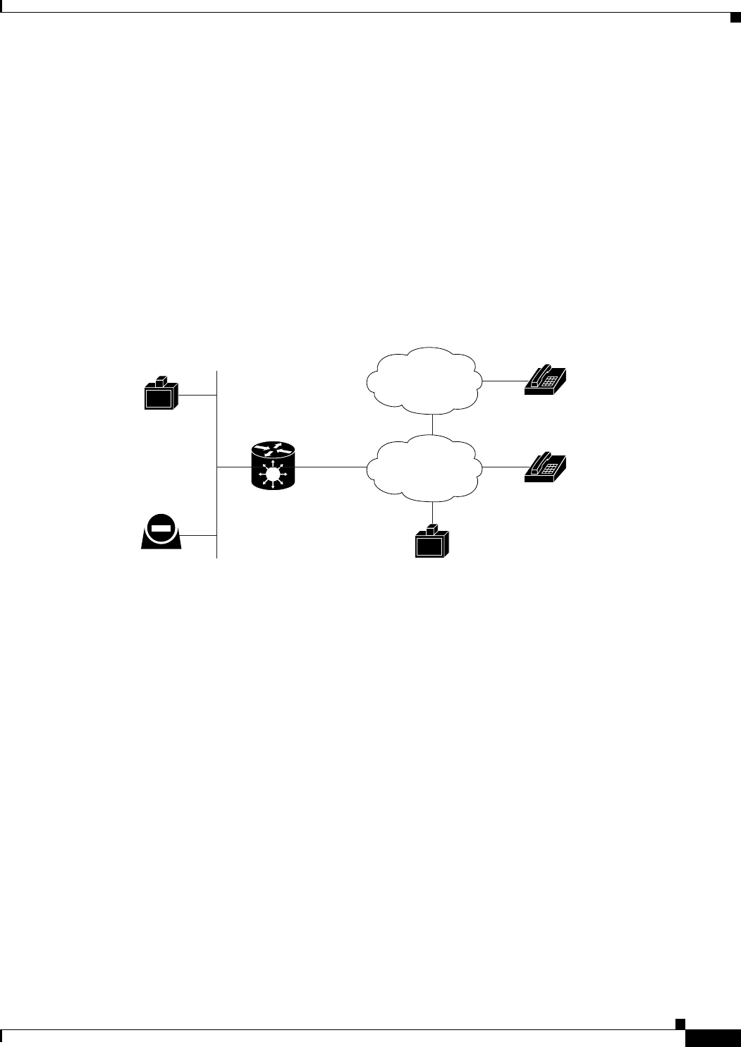
About Multimedia Conferencing
The Cisco PRI gateway enables H.323 endpoints on the IP network to communicate with an H.320
terminal, an ISDN phone, or a regular phone on a circuit-switched public network without having to
connect directly to these networks. The gateway allows all IP network terminals to support video
conferences without connecting every desktop computer to an ISDN line (see Figure 1-1).
Figure 1-1 Multimedia Conferencing through the Gateway
Typical multimedia conferencing applications include:
•Business video conferencing
•Distance learning
•Telemedicine
•Video-enabled call centers
•Telecommuting
157174
H.323
endpoint
H.323
terminal
ISDN
phone
Regular
phone
H.323
endpoint Cisco
chassis/unit
with serial
gateway
IP network PSDN
ISDN
1-8
Installation and Upgrade Guide for Cisco Unified Videoconferencing 3545 PRI Gateway and 3545 Serial Gateway Release 5.5
OL-14912-01
Chapter 1 Functionality
About Cisco Unified Videoconferencing 3545 Gateway Applications and Topologies
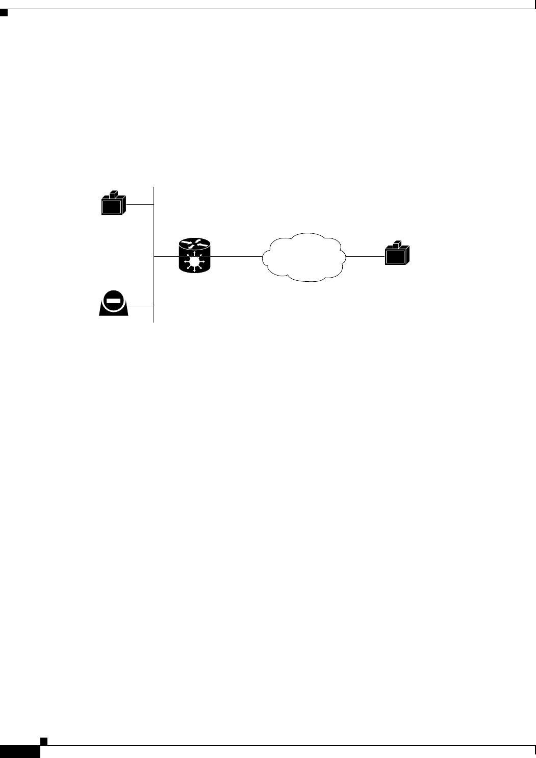
About Point-to-Point Conferencing
The Cisco PRI gateway enables direct video, voice, and data communication between an H.320 (ISDN)
terminal and H.323 (IP) terminals at bandwidths of up to 1472 Kbps (23B bonding for T1) and up to
1920 Kbps (30B bonding for E1).
Figure 1-2 Point-to-Point Conferencing through the Gateway
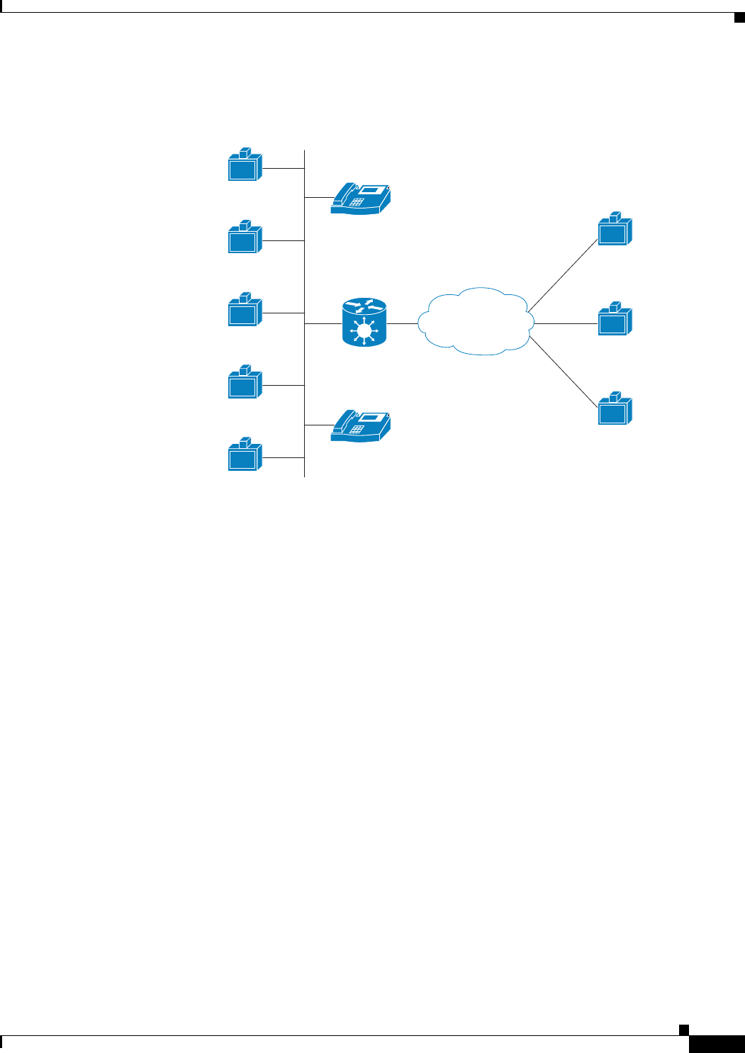
About Multipoint Conferencing
Together with the Cisco MCU, the Cisco PRI gateway enables H.320 ISDN terminals to participate in a
mixed ISDN-IP multipoint multimedia conference with IP network endpoints (see Figure 1-3).
For example, when an H.320 ISDN terminal wants to participate in a multipoint conference with H.323
IP endpoints, the H.320 ISDN terminal can either join the multipoint conference by dialing to the
gateway, or be invited into the conference by one of the participating IP endpoints. In either case, the
gateway connects the ISDN terminal to the Cisco MCU, enabling it to participate in the multipoint
conference.
157175
H.323
terminal
H.323
terminal
H.323
endpoint Cisco
chassis/unit
with serial
gateway
IP network
ISDN
1-9
Installation and Upgrade Guide for Cisco Unified Videoconferencing 3545 PRI Gateway and 3545 Serial Gateway Release 5.5
OL-14912-01
Chapter 1 Functionality
About Cisco Unified Videoconferencing 3545 Gateway Applications and Topologies
Figure 1-3 Mixed ISDN-IP Multipoint Multimedia Conference
About Gateway IP Network Connections
The Cisco PRI gateway features one 10/100Base-T Ethernet IP port (on the front panel) and connects to
an IP segment through a direct connection to a network switch.
About Gateway ISDN Network Connections
The Cisco PRI gateway features configurable E1/T1 PRI ISDN connections. When configured as an E1
connection, each port provides 30 B channels and one D signaling channel. When configured as a T1
connection, each port provides 23 B channels and one D signaling channel. The type of line available
depends on your local ISDN provider. You configure the gateway PRI port to an E1 or T1 interface
accordingly. In addition, you can choose to activate only specific channels by using fractional channel
selection.
H.323
Terminal
92871
H.323
Terminal
H.323
Terminal
H.323
Terminal
H.323
Terminal
H.320
Terminal
H.320
Terminal
H.320
Terminal
IP phone
IP
network
IP
IP phone
IP
ISDN
Cisco IPVC
Gateway
Cisco IPVC MCU
Cisco IPVC
chassis/unit
1-10
Installation and Upgrade Guide for Cisco Unified Videoconferencing 3545 PRI Gateway and 3545 Serial Gateway Release 5.5
OL-14912-01
Chapter 1 Functionality
About Cisco Unified Videoconferencing 3545 Gateway Applications and Topologies
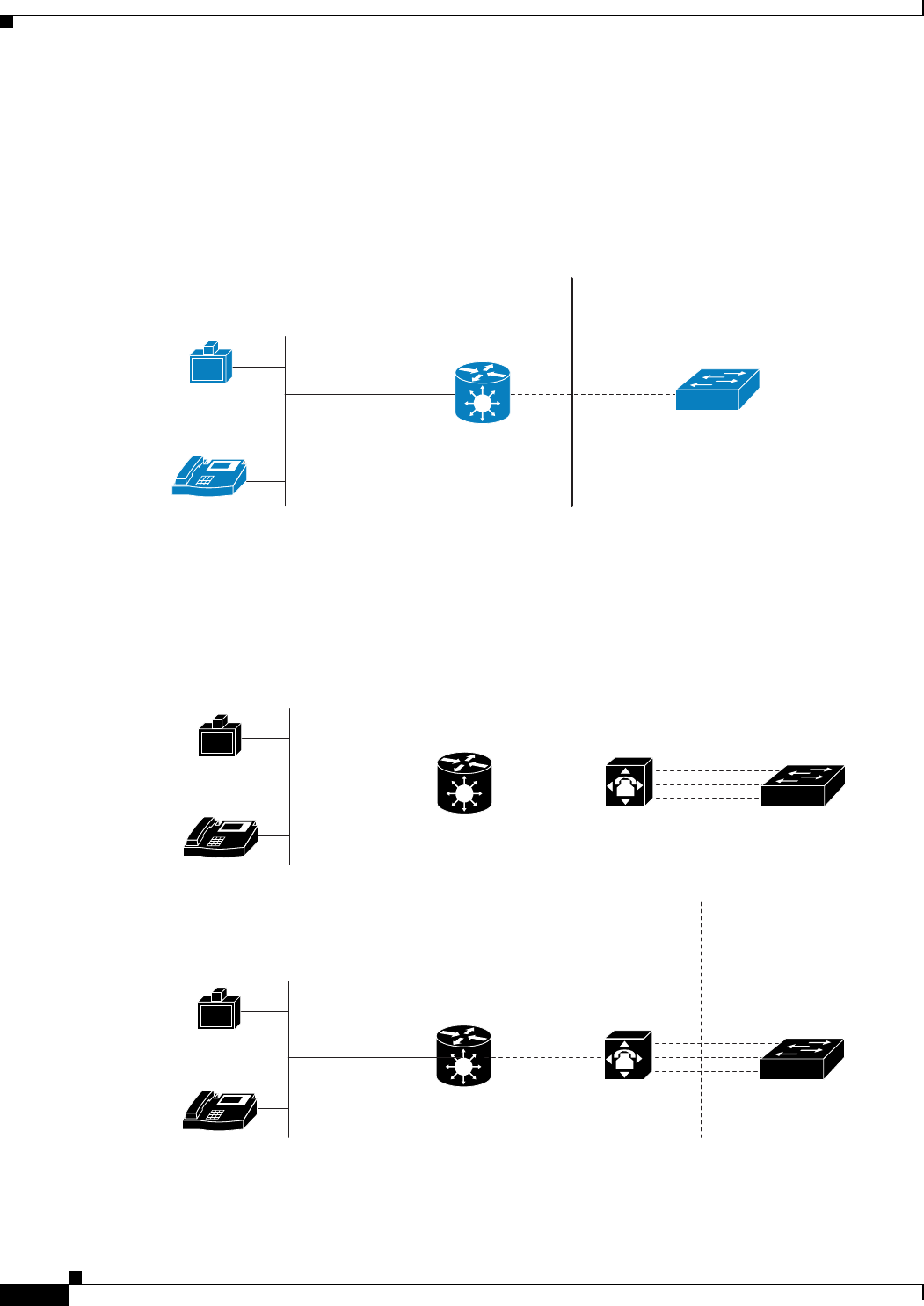
PRI Gateways
You can connect the PRI gateway directly to a PRI line provided by your local ISDN provider (as shown
in Figure 1-4), or to a local private branch exchange (PBX) that provides the PRI connection (as shown
in Figure 1-5).
Figure 1-4 Connecting the PRI Gateway Directly to a Central Office Switch
Figure 1-5 Connecting the PRI Gateway to a PBX that Provides a PRI Line
92873
H.323
Terminal
IP phone
IP
IP
network
Public
PRI T1/E1
Central office
switch
Private
Cisco IPVC
Gateway
Cisco IPVC
chassis/unit
157167
IP
H.323 terminal
IP phone
Cisco chassis/unit
Cisco Gateway
IP network
PRI T1/E1
Central Office
switch
PBX
PublicPrivate
157166
IP
H.323 terminal
IP phone
Cisco chassis/unit
Cisco Gateway
IP network
BRI
Central Office
switch
PBX
PublicPrivate
1-11
Installation and Upgrade Guide for Cisco Unified Videoconferencing 3545 PRI Gateway and 3545 Serial Gateway Release 5.5
OL-14912-01
Chapter 1 Functionality
About Cisco Unified Videoconferencing 3545 Gateway Applications and Topologies
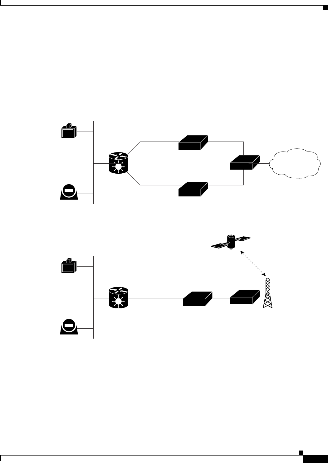
About Gateway Encryption
The serial gateway enables encrypted videoconferencing between H.323 endpoints on the IP network
and endpoints on remote sites by connecting to external encryption/decryption devices via serial
interfaces (as shown in Figure 1-6). The serial gateway also enables encrypted videoconferencing via
satellite with or without RS-366 signaling (as shown in Figure 1-7).
Figure 1-6 Encrypted Videoconferencing
Figure 1-7 Encrypted Videoconferencing via Satellite
157168
H.323
endpoint
H.323
endpoint Cisco
chassis/unit
with serial
gateway
IP network Isolator
RS-366
EIA-530A
RS-366
EIA-530A
DTE
IMUX
DCE
KIV-7
ISDN
157169
H.323
endpoint
H.323
endpoint Cisco
chassis/unit
with serial
gateway
IP network
KIV-7
Serial
DTE DCE
Satelite
access
1-12
Installation and Upgrade Guide for Cisco Unified Videoconferencing 3545 PRI Gateway and 3545 Serial Gateway Release 5.5
OL-14912-01
Chapter 1 Functionality
About Cisco Unified Videoconferencing 3545 Gateway Applications and Topologies
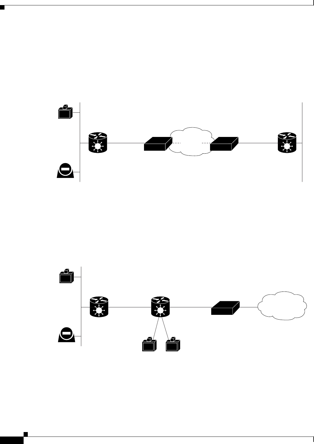
About Conferencing via Leased Lines
The serial gateway enables conferencing between H.323 endpoints on IP networks connected via a
leased line (as shown in Figure 1-8).
Figure 1-8 Conferencing via Leased Lines
About IP-to-Legacy MCU Conferencing
The serial gateway provides an IP-to-serial interface for communication with legacy MCU equipment
(as shown in Figure 1-9).
Figure 1-9 IP-to-Serial Interface Communication via Legacy MCU
Leased
line
157170
H.323
endpoint
H.323
endpoint Cisco
chassis/unit
with serial
gateway
Cisco
chassis/unit
with serial
gateway
IP network IP network
Adaptor Adaptor
V35.
DTE DCE
V35.
DCE DTE
157171
H.323
endpoint
H.323
endpoint Cisco
chassis/unit
with serial
gateway
IP network
IMUX
V35.
Legacy MCU
DTE
V.35
V35.
DCE
V.35
ISDN

1-13
Installation and Upgrade Guide for Cisco Unified Videoconferencing 3545 PRI Gateway and 3545 Serial Gateway Release 5.5
OL-14912-01
Chapter 1 Functionality
About Cisco Unified Videoconferencing 3545 Gateway Functionality
About Cisco Unified Videoconferencing 3545 Gateway
Functionality
This section discusses the following topics:
•About PRI Gateway Call Handling Capacity, page 1-13
•About Gateway Call Bandwidth Overhead, page 1-13
•About Peer-to-Peer Connectivity, page 1-14
About PRI Gateway Call Handling Capacity
Table 1-3 lists the maximum call handling capacity of the PRI gateway for different types of calls.
Note Enabling ISDN-to-IP DTMF detection in the PRI gateway for video calls reduces the number of
supported calls by half.
About Gateway Call Bandwidth Overhead
According to the H.320 standard, the available bandwidth allocated to a call at any given bit rate will
always be slightly less than the stated maximum for the following reasons:
•All stated maximum call bandwidths include provision for control, audio, video, and data traffic.
•Video traffic on the ISDN side contains additional bits for error correction purposes which also
consume bandwidth. Video traffic on the IP side does not include this additional load.
•Opening an audio channel further reduces the bandwidth available to the video traffic.
For example, a call at 384 Kbps actually has only 363 Kbps available to it. Control and error correction
account for the remaining 21 Kbps.
Table 1-3 PRI Gateway Call Handling Capacity
Call Type Maximum
Number of
Calls Using
1 x E1 PRI
Line
Maximum
Number of
Calls Using
1 X T1 PRI
Line
Maximum
Number of
Calls Using
2 x E1 PRI
Lines
Maximum
Number of
Calls Using
2 x T1 PRI
Lines
voice (64 Kbps)30236046
2B video (128 Kbps) 15 11 30 23
6B video (384 Kbps) 5 3 10 7
12B video (768 Kbps) 2 1 5 3

1-14
Installation and Upgrade Guide for Cisco Unified Videoconferencing 3545 PRI Gateway and 3545 Serial Gateway Release 5.5
OL-14912-01
Chapter 1 Functionality
About Cisco Unified Videoconferencing 3545 Gateway Functionality
Resource Allocation across E1/T1 Lines
The gateway can allocate bandwidth resources to calls across separate E1 or T1 connections to maximize
bandwidth capacity in cases where there is not enough capacity for a call on a single E1 or T1
connection, but where sufficient capacity does exist when remaining capacity on both E1/T1 lines is
combined.
For example, a gateway using two T1 lines can support three 6B calls on each T1 line, with 320 Kbps
spare capacity per line:
•Each T1 line provides 23 B channels.
•Each B channel supports 64 Kbps
•Each T1 line supports 23 x 64 = 1472 Kbps
•Each 6B call requires 6 x 64 = 384 Kbps
•Each T1 line supports 1472/384 = 3 6B calls + 320 Kbps spare
The gateway processes an additional 6B call requiring a further 384 Kbps by taking bandwidth resources
from each of the two T1 lines, both of which have 320 Kbps available. In this way, the gateway spreads
the call over both T1 lines.
About Peer-to-Peer Connectivity
The gateway supports the following types of connectivity to the IP network
•Through a gatekeeper
•Directly to a peer device such as Cisco Unified Communications Manager without the need for a
gatekeeper.

CHAPTER
2-1
Installation and Upgrade Guide for Cisco Unified Videoconferencing 3545 PRI Gateway and 3545 Serial Gateway Release 5.5
OL-14912-01
2
Installing the Cisco Unified
Videoconferencing 3545 Gateway
This section describes the following topics:
•Physical Description, page 2-1
•Preparing for Installation, page 2-3
•Verifying the Package Contents, page 2-4
•Mounting the Cisco Unified Videoconferencing 3545 Chassis in a 19-inch Rack, page 2-5
•Installing the Gateway, page 2-6
•Initial Gateway Configuration, page 2-10
•Connecting the Gateway to the Network, page 2-14
•Connecting PRI Lines to the Gateway, page 2-14
•Connecting Serial Lines to the Gateway, page 2-14
•Serial Gateway Cable Connections and Pin-outs, page 2-15
•Connecting the Gateway to a Power Source, page 2-27
•Accessing the Gateway Administrator Interface, page 2-27
•Registering the Online Help, page 2-28
Physical Description
This section provides a physical description of the gateway modules and their corresponding RTMs.
Gateway Module
The gateway module has a 10/100BaseT Ethernet port on the front panel that uses an RJ-45 connector
to connect to the network. There is an asynchronous, 9-pin serial port that you can use with a
hyperterminal program to configure and monitor the module.
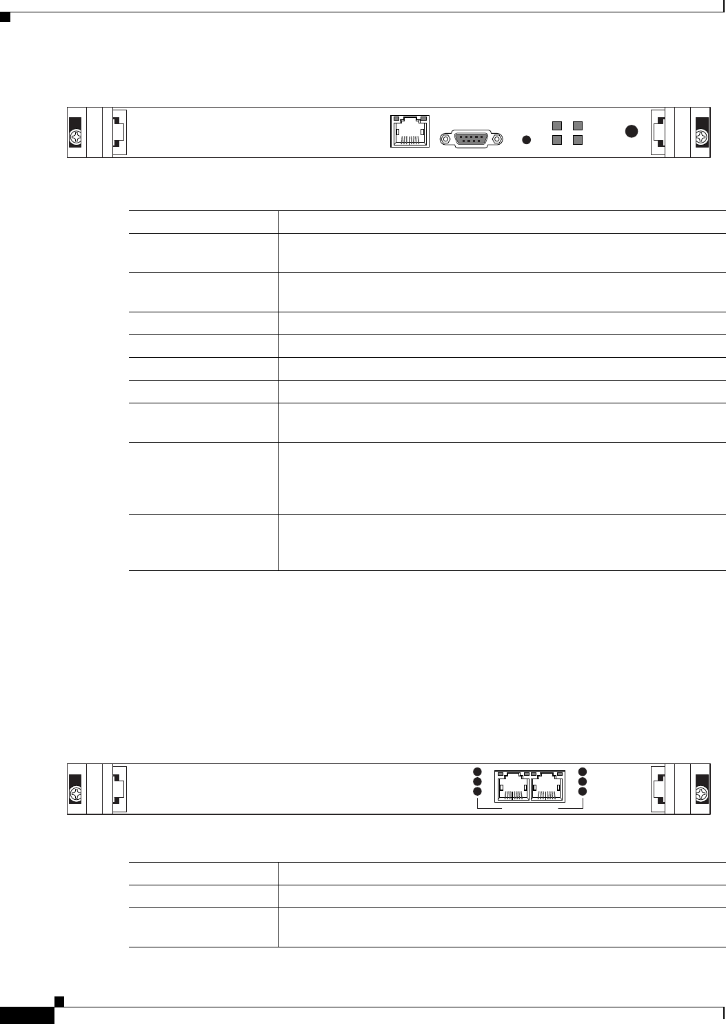
Figure 2-1 shows the front panel components of the gateway module. Table 2-1 describes these
components.
2-2
Installation and Upgrade Guide for Cisco Unified Videoconferencing 3545 PRI Gateway and 3545 Serial Gateway Release 5.5
OL-14912-01
Chapter 2 Installing the Cisco Unified Videoconferencing 3545 Gateway
Physical Description
Figure 2-1 Gateway Front Panel
Cisco Unified Videoconferencing 3545 PRI Gateway RTM
The Rear Transition Module (RTM) provides the PRI line connections for the Cisco Unified
Videoconferencing 3545 PRI Gateway.
Figure 2-2 shows the RTM panel components of the Cisco Unified Videoconferencing 3545
PRI Gateway module. Table 2-2 describes these components.
Figure 2-2 PRI Gateway: Rear Transition Module
Table 2-1 Front Panel Components
Component Description
10/100 Base T-1
connector
An RJ-45 connector that provides the primary Ethernet connection for the IP
network port.
SERIAL connector A DB-9 connector that allows you to connect a PC terminal for local
configuration.
RST button Allows you to reset the gateway manually.
GK Reg LED Lights green when the gateway is registered with a gatekeeper.
CD LED Lights green when at least one gateway port connection is online.
ACT LED Lights green to indicate that there are active calls in the gateway.
ALARM LED Lights green to indicate that an error has occurred and the gateway requires
resetting.
10/100 Base T-1 LEDs The top part of the 10/100 Base T-1 connector contains two LED indicators.
The left-hand LED lights green when the local IP network link is active. The
right-hand LED lights green if the connection speed is 100 Mbps, and is off
when the connection speed is 10 Mbps.
SWAP RDY LED Hot Swap indication. Lights blue when the latches of a board are unlocked
and it is safe to remove the board from the chassis. Goes off when the board
is completely detached.
157269
10/100Base T-1
SERIAL
RST ACTALARM
CDGK Reg
SWAP
RDY
Table 2-2 PRI Gateway Rear Transition Module Components
Component Description
ACT LEDs Lights green to indicate that there are active calls in the gateway.
D-Ch LEDs Lights green to indicate that the PRI line is enabled and a carrier signal is
detected.
157272
PORT-1PORT-2
ACT
D-Ch
ALARM
ACT
D-Ch
ALARM
2-3
Installation and Upgrade Guide for Cisco Unified Videoconferencing 3545 PRI Gateway and 3545 Serial Gateway Release 5.5
OL-14912-01
Chapter 2 Installing the Cisco Unified Videoconferencing 3545 Gateway
Preparing for Installation
Cisco Unified Videoconferencing 3545 Serial Gateway RTM
The Rear Transition Module (RTM) provides the serial line connections for the Cisco Unified
Videoconferencing 3545 Serial Gateway.
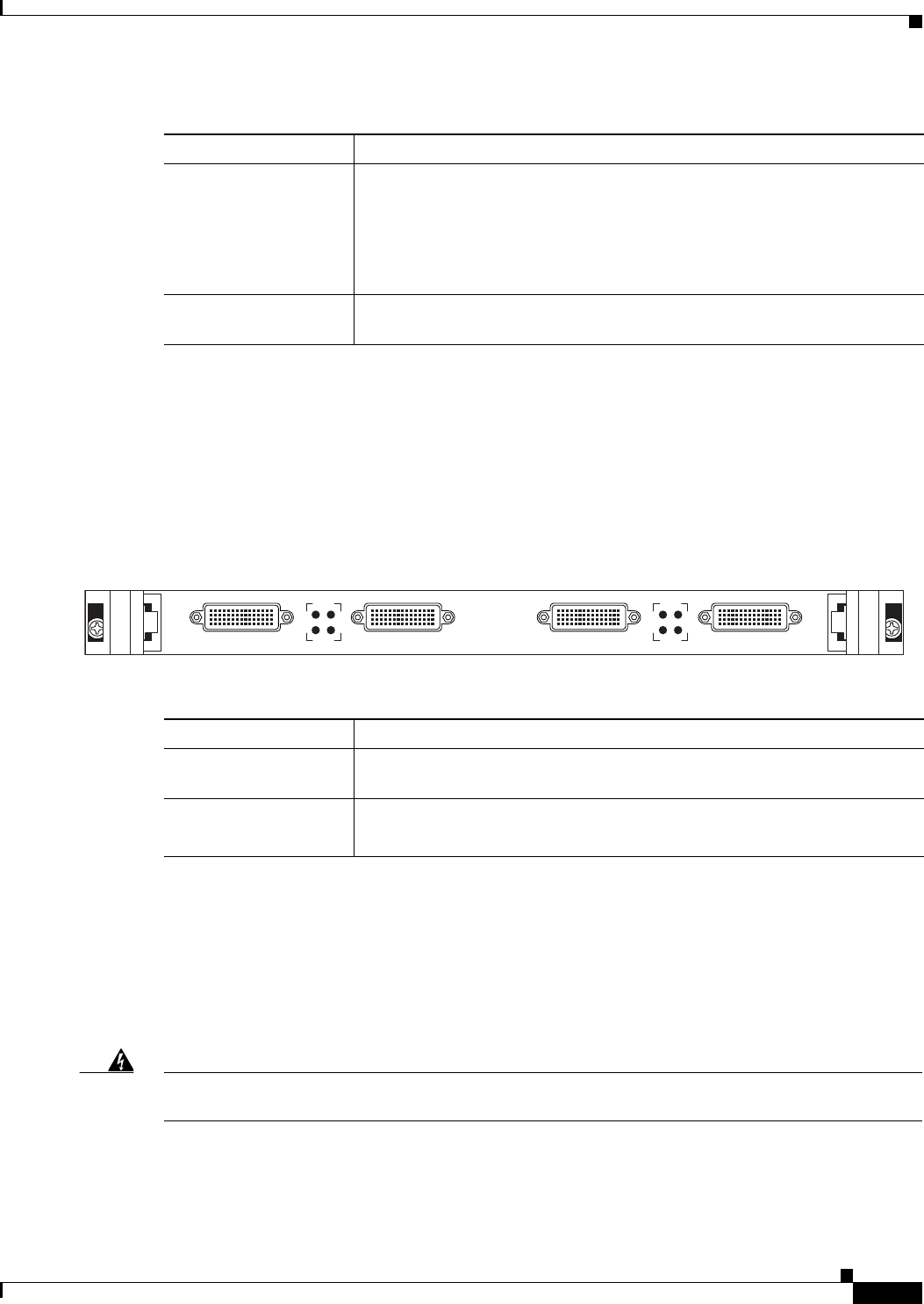
Figure 2-3 shows the RTM panel components of the Cisco Unified Videoconferencing 3545
Serial Gateway module. Table 2-3 describes these components.
Figure 2-3 Serial Gateway: Rear Transition Module
Preparing for Installation
This section describes the requirements for installing the Cisco Unified Videoconferencing 3545
PRI Gateway and the Cisco Unified Videoconferencing 3545 Serial Gateway in a Cisco Unified
Videoconferencing 3545 chassis. For more information, see the Platform Guide for Cisco IPVC 3644
Chassis. The requirements are as follows:
Warning
During this procedure, wear grounding wrist straps to avoid ESD damage to the card. Do not directly
touch the backplane with your hand or any metal tool, or you could shock yourself.
•Cisco Unified Videoconferencing 3545 chassis
•Proper clearance at the sides of the unit to allow adequate ventilation, and at least 20 cm clearance
at the back of the chassis to allow access to the boards and cable connections
ALARM LEDs Displays alarm events for the PRI line.
•YELLOW —Lights yellow when there is a loss of frame alignment at the
remote side.
•ORANGE—Lights orange when there is a loss of frame alignment in the
gateway.
PRI LINE connectors RJ-45 connectors that provide the PRI line connections for the specified
gateway ISDN PRI port.
Table 2-2 PRI Gateway Rear Transition Module Components (continued)
Component Description
Table 2-3 Serial Rear Transition Module Components
Component Description
PORT connectors DB-60 connectors that provide the serial line connections for gateway serial
ports 1 to 4.
ACT and ALARM
LEDs
ACT lights green to indicate that the specified serial line is currently in use.
ALARM lights red to indicate an internal error related to the specified line.
157273
PORT-4 ALARM
ACT
43
PORT-3 PORT-2 ALARM
ACT
21
PORT-1

2-4
Installation and Upgrade Guide for Cisco Unified Videoconferencing 3545 PRI Gateway and 3545 Serial Gateway Release 5.5
OL-14912-01
Chapter 2 Installing the Cisco Unified Videoconferencing 3545 Gateway
Verifying the Package Contents
•A PC with a serial port and terminal emulation software to assign the gateway an IP address
•Dedicated IP address for the gateway
•The IP address of the router the gateway will use to communicate across the network
•The IP address of the H.323 gatekeeper with which you want the gateway to register
•Available IP network ports on the switch for the Cisco Unified Videoconferencing 3545 chassis
•A grounded AC power outlet
•A 10BaseT or 100BaseT LAN cable
•Ambient room temperature range of 32o to 104oF (0o to 40oC)
•Non-condensing relative humidity range of 5% to 85%
Verifying the Package Contents
Inspect the contents of the box for shipping damage. Report any damage or missing items to your Cisco
representative. Table 2-4 lists the package contents for the gateway.
You can also order the following cables for the Cisco Unified Videoconferencing 3545 Serial Gateway:
•V.35/RS366-DTE cable
•EIA449/RS366-DTE cable
•EIA530/RS366-DTE cable
•EIA530/RS366-DTE-LOS cable
•EIA530A/RS366-DTE cable
•KIV7/RS366-DTE cable
•V.35/RS366-DCE cable
•EIA449/RS366-DCE cable
•EIA530/RS366-DCE cable
Table 2-4 Package Contents with Cisco Unified Videoconferencing 3545 PRI Gateway or
Cisco Unified Videoconferencing 3545 Serial Gateway
Product Contents
Cisco Unified
Videoconferencing 3545 chassis with
Cisco Unified Videoconferencing 3545
PRI Gateway or Cisco Unified
Videoconferencing 3545 Serial Gateway
•Cisco Unified Videoconferencing 3545 PRI Gateway or
Cisco Unified Videoconferencing 3545 Serial Gateway
•Cisco Unified Videoconferencing 3545 PRI Gateway or
Cisco Unified Videoconferencing 3545 Serial Gateway
Rear Transition Module
•LAN cable
•Regulatory Compliance and Safety Information for
Cisco Unified Videoconferencing 3500 Products
•Cisco Unified Videoconferencing Software CD-ROM
•Cisco Information Package
2-5
Installation and Upgrade Guide for Cisco Unified Videoconferencing 3545 PRI Gateway and 3545 Serial Gateway Release 5.5
OL-14912-01
Chapter 2 Installing the Cisco Unified Videoconferencing 3545 Gateway
Mounting the Cisco Unified Videoconferencing 3545 Chassis in a 19-inch Rack
Related Topics
•Serial Gateway Cable Connections and Pin-outs, page 2-15
Mounting the Cisco Unified Videoconferencing 3545 Chassis in
a 19-inch Rack
You can optionally mount the Cisco Unified Videoconferencing 3545 chassis in a standard 19-inch rack.
Two mounting brackets and a set of screws are included in the Cisco Unified
Videoconferencing 3545 chassis shipping box.
Procedure
Step 1 Disconnect all cables including the power cables.
Step 2 Place the Cisco Unified Videoconferencing 3545 chassis right-side up on a hard flat surface, with the
front panel facing you.
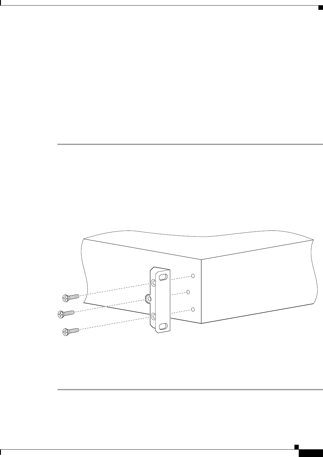
Step 3 Position a mounting bracket over the mounting holes on each side of the Cisco Unified
Videoconferencing 3545 chassis, as shown in Figure 2-4.
Step 4 Pass the screws through the brackets and tighten them into the screw holes on each side of the
Cisco Unified Videoconferencing 3545 chassis using a suitable screwdriver.
Figure 2-4 Fitting a Bracket for Rack Mounting
Step 5 Insert the Cisco Unified Videoconferencing 3545 chassis into the 19-inch rack.
Step 6 Fasten the brackets to the side rails of the rack.
Step 7 Make sure that the air vents at the sides of the Cisco Unified Videoconferencing 3545 chassis are not
blocked.
157267

2-6
Installation and Upgrade Guide for Cisco Unified Videoconferencing 3545 PRI Gateway and 3545 Serial Gateway Release 5.5
OL-14912-01
Chapter 2 Installing the Cisco Unified Videoconferencing 3545 Gateway
Installing the Gateway
Installing the Gateway
This section describes how to insert a gateway into the Cisco Unified Videoconferencing 3545 chassis.
Before You Begin
Note the following:
•The Cisco Unified Videoconferencing 3545 chassis has four slots. You can install the Cisco Unified
Videoconferencing 3545 Gateway in any of the slots.
•Insert the gateway in the top slot at the front of the Cisco Unified Videoconferencing 3545 chassis
to view status and identification information via the System web user interface.
The Cisco Unified Videoconferencing 3545 Gateway has two components that you must install in the
chassis: the Cisco Unified Videoconferencing 3545 Gateway module and the corresponding Rear
Transition Module (RTM), as indicated in Table 2-5.
The gateway module installs in the front of the chassis and provides ISDN or serial functionality. The
RTM installs in the rear of the chassis and provides the physical interface for the ISDN or serial line.
You must install these modules in corresponding slots in the chassis. That is, if you insert the gateway
module in the top slot in the front of the chassis, you must insert the RTM in the top slot in the rear of
the chassis.
Warning During this procedure, wear grounding wrist straps to avoid ESD damage to the card. Do not directly touch the
backplane with your hand or any metal tool, or you could shock yourself.
Only trained and qualified personnel should be allowed to install, replace, or service this equipment.
Before working on a system that has an on/off switch, turn OFF the power and unplug the power cord.
Before opening the chassis, disconnect the telephone network cables to avoid contact with telephone network
voltages.
To avoid electric shock, do not connect safety extra-low voltage (SELV) circuits to telephone-network voltage (TNV)
circuits. LAN ports contain SELV circuits, and WAN ports contain TNV circuits. Some LAN and WAN ports both use
RJ-45 connectors. Use caution when connecting cables.
The telecommunications lines must be disconnected 1) before unplugging the main power connector and/or 2) while
the housing is open.
Table 2-5 Identifying RTM Boards
Gateway Corresponding RTM
Cisco Unified Videoconferencing 3545
PRI Gateway
Dual PRI RTM board
Cisco Unified Videoconferencing 3545
Serial Gateway
Quad Serial RTM board
2-7
Installation and Upgrade Guide for Cisco Unified Videoconferencing 3545 PRI Gateway and 3545 Serial Gateway Release 5.5
OL-14912-01
Chapter 2 Installing the Cisco Unified Videoconferencing 3545 Gateway
Installing the Gateway
Installing the RTM Module
This section describes how to install the RTM module in the Cisco Unified
Videoconferencing 3545 chassis. The Rear Transition Module (RTM) provides the ISDN or serial line
connections for the gateway.
Warning
You must install the RTM module before you install the gateway module. Inserting an RTM module in
the rear of the chassis when a gateway module is already installed in the same position at the front
of the chassis may damage the chassis.
Procedure
Step 1 On the back of the chassis, loosen the screws of the blank panel covering the slot into which the RTM
module is to be installed.
Step 2 Remove the blank panel.
Step 3 Remove the new RTM from the antistatic bag.
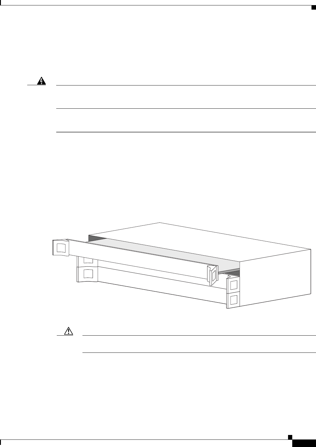
Step 4 Press the red buttons and open the handles of the RTM module.
Step 5 Align the edges of the RTM module with the chassis guide rails.
Step 6 Slide the RTM module into the chassis until it stops (see Figure 2-5).
Figure 2-5 Inserting the RTM Module in the Cisco Unified Videoconferencing 3545 Chassis
Step 7 Use even pressure to push the module further into the slot.
Caution Do not force the connection. Forcing the connection can bend or damage the pins in the
connector inside the chassis.
Step 8 Snap the handles forward to secure the RTM module in the slot.
Step 9 Secure the RTM module screws.
157274

2-8
Installation and Upgrade Guide for Cisco Unified Videoconferencing 3545 PRI Gateway and 3545 Serial Gateway Release 5.5
OL-14912-01
Chapter 2 Installing the Cisco Unified Videoconferencing 3545 Gateway
Installing the Gateway
Caution Blank faceplates and cover panels serve three important functions: they prevent exposure to
hazardous voltages and currents inside the chassis; they contain electromagnetic interference
(EMI) that might disrupt other equipment; and they direct the flow of cooling air through the
chassis. Do not operate the system unless all cards, faceplates, front covers, and rear covers
are in place.
Installing the Gateway Module
This section describes how to install the Cisco Unified Videoconferencing 3545 Gateway module in the
Cisco Unified Videoconferencing 3545 chassis.
Warning
You must install the RTM module before you install the gateway module. Inserting an RTM module in
the rear of the chassis when a gateway module is already installed in the same position at the front
of the chassis may damage the chassis.
Procedure
Step 1 On the front of the chassis, loosen the screws of the blank panel covering the slot into which the gateway
module is to be installed.
Step 2 Remove the blank panel.
Step 3 Remove the new gateway module from the antistatic bag.
Step 4 Press the red buttons and open the handles of the gateway module.
Step 5 Align the edges of the gateway module with the chassis guide rails.
Step 6 Slide the gateway module into the chassis until it stops (see Figure 2-5 for the Cisco Unified
Videoconferencing 3545 chassis).
Step 7 Use even pressure to push the module further into the slot.
Caution Do not force the connection. Forcing the connection can bend or damage the pins in the
connector inside the chassis.
Note If you are installing the gateway module and the power to the chassis is on, the SWAP RDY LED
on the module front panel turns blue when you slide the module into the chassis as far as it will
go. This means that you can secure the module safely. The LED turns off when the handles are
closed.
Step 8 Snap the handles forward to secure the gateway module in the slot.
Step 9 Secure the gateway module screws.
2-9
Installation and Upgrade Guide for Cisco Unified Videoconferencing 3545 PRI Gateway and 3545 Serial Gateway Release 5.5
OL-14912-01
Chapter 2 Installing the Cisco Unified Videoconferencing 3545 Gateway
Installing the Gateway
Caution Blank faceplates and cover panels serve three important functions: they prevent exposure to
hazardous voltages and currents inside the chassis; they contain electromagnetic interference
(EMI) that might disrupt other equipment; and they direct the flow of cooling air through the
chassis. Do not operate the system unless all cards, faceplates, front covers, and rear covers
are in place.
Removing a Module
This section describes how to remove the Cisco Unified Videoconferencing 3545 Gateway or the RTM
module from the Cisco Unified Videoconferencing 3545 chassis.
Warning
You must remove the gateway module from the slot at the front of the chassis before removing the
corresponding RTM module from the same slot position at the rear of the chassis.
Procedure
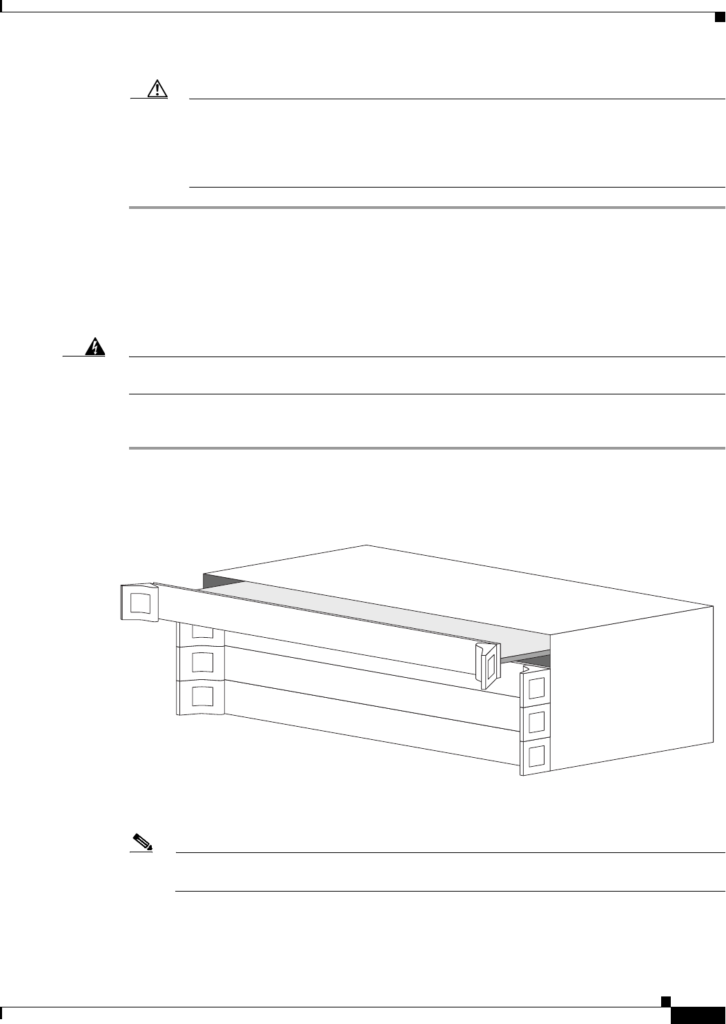
Step 1 Loosen the gateway or RTM module screws.
Step 2 Press the red buttons and open the handles of the gateway or RTM module (see Figure 2-6).
Figure 2-6 Removing a Module from the Cisco Unified Videoconferencing 3545 Chassis
Step 3 Wait for the blue SWAP RDY LED to light up. The SWAP RDY LED indicates that it is safe to remove
the module.
Note It may take up to one minute for the LED to light up while the Windows operating system is
shutting down.
The light goes out when the board is completely detached from the backplane.
Step 4 Remove the module completely.
157279

2-10
Installation and Upgrade Guide for Cisco Unified Videoconferencing 3545 PRI Gateway and 3545 Serial Gateway Release 5.5
OL-14912-01
Chapter 2 Installing the Cisco Unified Videoconferencing 3545 Gateway
Initial Gateway Configuration
Step 5 Insert a blank cover panel provided by Cisco.
Step 6 Secure the blank cover panel screws.
Caution Blank faceplates and cover panels serve three important functions: they prevent exposure to
hazardous voltages and currents inside the chassis; they contain electromagnetic interference
(EMI) that might disrupt other equipment; and they direct the flow of cooling air through the
chassis. Do not operate the system unless all cards, faceplates, front covers, and rear covers
are in place.
Initial Gateway Configuration
Initial monitoring and administration of the gateway are performed from a remote PC via a serial
connection. This allows you to access the boot configuration menu of the gateway. At power-up, the
gateway goes through the following boot phases:
•Auto-boot—The embedded operating system initializes and displays basic information.
•Configuration menu—A 6-second countdown allows you to enter the configuration menu.
•Initialization—The gateway completes its boot sequence and is ready for operation.
Note You can perform serial port configuration of the gateway only at startup, during a short period indicated
by a 6-second countdown. Once the initialization phase is complete, the only way you can access the
configuration menu is by restarting the gateway.
Connecting to a PC
This section describes how to use the serial port connection to configure the gateway with an IP address.
Procedure
Step 1 Locate the terminal cable shipped with the gateway.
Step 2 Connect the end labeled PC to the serial port on the computer.
Step 3 Connect the end labeled Unit to the serial port connector on the gateway front panel.
Note The PC terminal should have an installed terminal emulation application, such as HyperTerminal.

2-11
Installation and Upgrade Guide for Cisco Unified Videoconferencing 3545 PRI Gateway and 3545 Serial Gateway Release 5.5
OL-14912-01
Chapter 2 Installing the Cisco Unified Videoconferencing 3545 Gateway
Initial Gateway Configuration
Setting the IP Address
This section describes how to use the serial port to configure the unit with an IP address and other
address information.
The serial port on the gateway front panel is used to assign a new IP address to your gateway. You must
assign the IP address before you connect the gateway to the network.
Before You Begin
Gather the items listed in Table 2-6 to assign an IP address to the gateway.
Procedure
Step 1 Connect the supplied terminal cable to the PC terminal.
Step 2 Connect the power cable.
Step 3 Start the terminal emulation application on the PC.
Step 4 Set the communication settings in the terminal emulation application on the PC as follows:
•Baud rate: 9600
•Data bits: 8
•Parity: None
•Stop bits: 1
•Flow control: None
Step 5 Turn on the power to the gateway.
Step 6 After the terminal emulator session starts, press the RST button on the gateway front panel to reset the
module.
A log of the auto-boot events and a VxWorks banner scrolls across the computer monitor.
Note When the gateway is started for the first time, two VxWorks banners appear. The configuration
option appears after the second banner.
Step 7 When the message “Press any key to start configuration” appears on the screen, press any key within 6
seconds.
Table 2-6 Requirements for Setting the IP Address
Requirements Notes
Dedicated IP address for the gateway
IP address of the default router the
gateway uses to communicate over the
network
PC with available serial port and
terminal emulator software installed
RS-232 terminal cable (shipped with
the unit)

2-12
Installation and Upgrade Guide for Cisco Unified Videoconferencing 3545 PRI Gateway and 3545 Serial Gateway Release 5.5
OL-14912-01
Chapter 2 Installing the Cisco Unified Videoconferencing 3545 Gateway
Initial Gateway Configuration
The network configuration Main menu displays:
Press any Key To start configuration...
Main menu
Enter <N> to configure default network port values
Enter <P> to change the configuration software password
Enter <A> to display advanced configuration menu
Enter <Q> to quit configuration menu and start GW
Caution If you do not press a key before the countdown ends, the device continues its initialization and
you can only configure the device by pressing the RST button on the front panel.
Step 8 At the prompt, type N to configure default network port values and press Enter.
Step 9 At the Enter IP address for default interface prompt, type the IP address you want to assign to the
gateway and press Enter.
Caution Do not use leading zeros in the IP address.
Step 10 At the Enter Default Router IP Address prompt, type the IP address of the router associated with the
segment in which the unit will be installed and press Enter.
Caution Do not use leading zeros in the IP address.
Step 11 At the Enter IP Mask for default device prompt, type the subnet mask without leading zeros, and then
press Enter. If a subnet mask is not used, press Enter.
Step 12 Allow the unit to complete the reboot process. A new emulator session begins.
Step 13 Close the terminal emulator session.
Changing the Configuration Tool Login Password
You can use the terminal emulator to change the default password of the default login user before others
can use the gateway interface.
Procedure
Step 1 Start a terminal emulator session for the gateway.
Step 2 Press the RST button on the front panel of the gateway.
After 60 seconds, a new terminal emulator session begins on the computer monitor.
Step 3 After the second VxWorks banner scrolls across the screen, the following message appears: “Press any
Key to start the configuration.”
Step 4 Press any key and then press Enter.
Step 5 At the prompt, enter P and press Enter to select “change the configuration software password.”
Step 6 Type the user login name for which you want to change the password and press Enter.
The default user name is admin. This is the user name that allows you to access the gateway interface.

2-13
Installation and Upgrade Guide for Cisco Unified Videoconferencing 3545 PRI Gateway and 3545 Serial Gateway Release 5.5
OL-14912-01
Chapter 2 Installing the Cisco Unified Videoconferencing 3545 Gateway
Initial Gateway Configuration
Step 7 Type the password you want the user to use to log in to the gateway interface and press Enter.
There is no default password.
Step 8 The network configuration Main menu re-appears.
Step 9 Enter Q and press Enter to exit.
Upgrading Gateway Software
Software upgrades for the gateway include the software components that are upgraded for the new
version and a utility to upload the software to the unit. This section describes how to upgrade the
software. For more information, see Chapter 3, “Using the Cisco Software Upgrade Utility”.
Procedure
Step 1 Download the upgrade software to a host that can access the gateway.
Step 2 Unzip the upgrade file.
Step 3 Double click the upgrade.exe file.
Step 4 In the Target IP field, type the IP address of the gateway for which you want to upload the software.
Step 5 In the User Name field, type the software user name.
This is a global login name that the upload, upgrade, and Telnet utilities use to log in to the gateway
software. It can also be used to access the Administrator interface. The default user name is admin.
Step 6 In the Password field, type the software password.
The default value is null.
Note To view the software components that will upgrade, click Customize. The Customize dialog
box appears. If you do not want to upgrade a component, deselect it.
Step 7 Click Upgrade.
The upgrade process takes a few minutes. After the upload completes, the Upload Complete Message
dialog box appears.
Step 8 Click OK.

2-14
Installation and Upgrade Guide for Cisco Unified Videoconferencing 3545 PRI Gateway and 3545 Serial Gateway Release 5.5
OL-14912-01
Chapter 2 Installing the Cisco Unified Videoconferencing 3545 Gateway
Connecting the Gateway to the Network
Connecting the Gateway to the Network
The Cisco Unified Videoconferencing 3545 Gateway can connect to the LAN only through the front
panel. The gateway supports a 10/100BaseT, full-duplex Ethernet interface through an RJ-45 connector.
Procedure
Step 1 Connect the supplied LAN cable from your network hub to the 10/100BaseT Ethernet port on the front
panel of the gateway. The 10/100BaseT port accepts an RJ-45 connector.
Step 2 Connect a separate ISDN or serial line to each PRI or serial port in the rear panel of the gateway. The
port accepts an RJ-45 connector.
Connecting PRI Lines to the Gateway
You must connect a PRI line to at least one Cisco Unified Videoconferencing 3545 PRI Gateway port.
The gateway supports T1 and E1 PRI configurations.
Connecting Serial Lines to the Gateway
You can connect the Cisco Unified Videoconferencing 3545 Serial Gateway to four serial lines that may
support different physical standards (V.35, RS-449 or EIA-530). The system is capable of recognizing
the type of cable connected.
Procedure
Step 1 Connect the DB-60 male connector of the cable to the DB-60 female connector of the unit.
Step 2 Tighten the screws.
Step 3 Connect the remote connectors (V.35, RS-449, EIA-530 and RS-366) to the connectors or the connecting
cable of the remote equipment

2-15
Installation and Upgrade Guide for Cisco Unified Videoconferencing 3545 PRI Gateway and 3545 Serial Gateway Release 5.5
OL-14912-01
Chapter 2 Installing the Cisco Unified Videoconferencing 3545 Gateway
Serial Gateway Cable Connections and Pin-outs
Serial Gateway Cable Connections and Pin-outs
This section describes the DTE and DCE cables that you can use with the Cisco Cisco Unified
Videoconferencing 3545 Serial Gateway including the following topics:
•Physical Description of DTE Cables, page 2-15
•Physical Description of DCE Cables, page 2-19
•Data Interface Cable Pin-out Configurations, page 2-21
•Data Interface Pin Layouts, page 2-22
•Signaling Interface Cable Pin-out Configuration, page 2-25
•Signaling Interface Pin Layout, page 2-26
Physical Description of DTE Cables
This section describes the following DTE cables supplied with the Cisco Cisco Unified
Videoconferencing 3545 Serial Gateway:
•V.35/RS366-DTE, page 2-16
•EIA449/RS366-DTE, page 2-16
•EIA530/RS366-DTE, page 2-17
•EIA530/RS366-DTE-LOS, page 2-17
•EIA530A/RS366-DTE, page 2-18
•KIV7/RS366-DTE, page 2-18
Note • The DB-25 connector provides the data interface for the EIA530/RS366-DTE and
EIA530/RS366-DTE-LOS cables.
•The DB-37 connector provides the data interface for the EIA449/RS366-DTE and
KIV7/RS366-DTE cables.
•The DB-25 connector provides the RS-366 signaling interface for all Cisco Unified
Videoconferencing 3545 Serial Gateway cables.
2-16
Installation and Upgrade Guide for Cisco Unified Videoconferencing 3545 PRI Gateway and 3545 Serial Gateway Release 5.5
OL-14912-01
Chapter 2 Installing the Cisco Unified Videoconferencing 3545 Gateway
Serial Gateway Cable Connections and Pin-outs
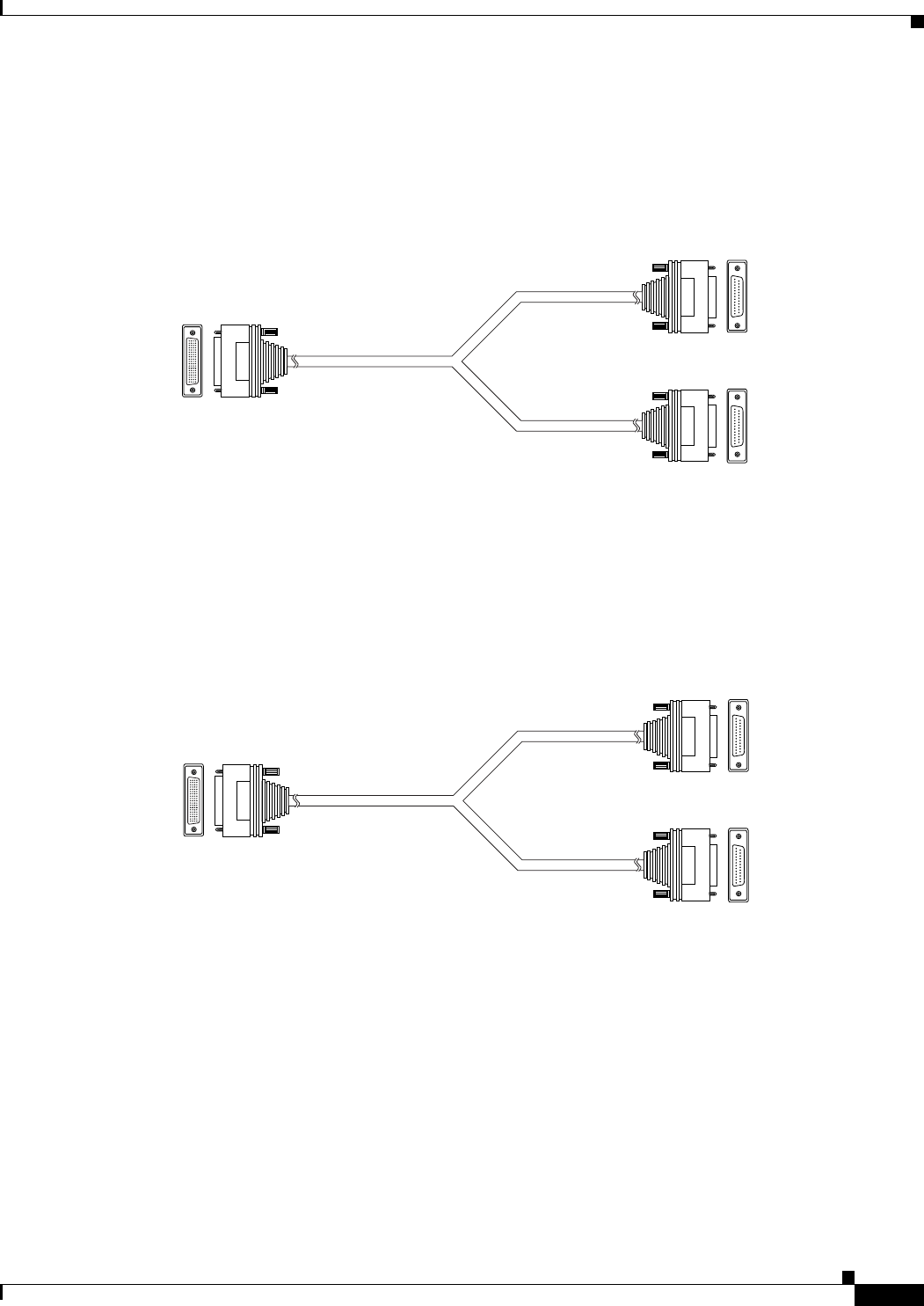
V.35/RS366-DTE
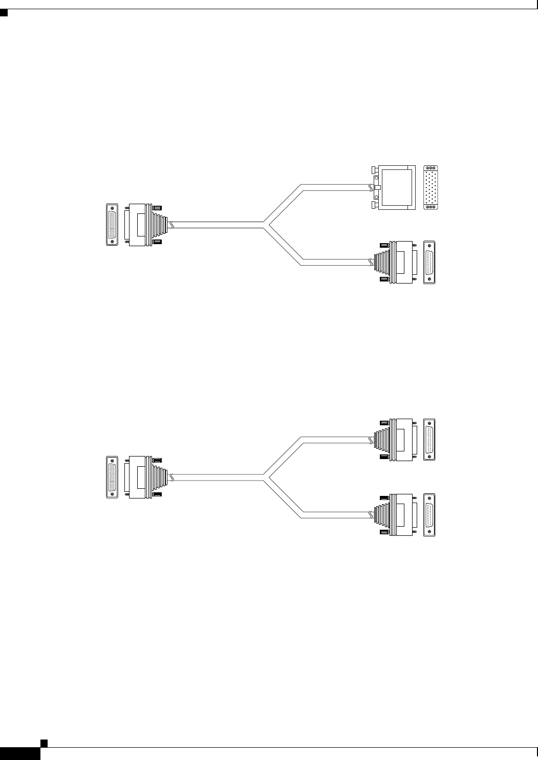
Figure 2-7 shows the V.35/RS366-DTE cable.
Figure 2-7 V.35/RS366-DTE Cable
EIA449/RS366-DTE
Figure 2-8 shows the EIA449/RS366-DTE cable.
Figure 2-8 EIA449/RS366-DTE Cable
157179
J1 Male (DB-60)
J2 Male
(M-34 Winchester)
V.35 data
RS-366
signaling
J3 Male (DB-25)
157158
J1 Male (DB-60)
J2 Male (DB-37)
J3 Male (DB-25)
EIA-449 data
RS-366
signaling
2-17
Installation and Upgrade Guide for Cisco Unified Videoconferencing 3545 PRI Gateway and 3545 Serial Gateway Release 5.5
OL-14912-01
Chapter 2 Installing the Cisco Unified Videoconferencing 3545 Gateway
Serial Gateway Cable Connections and Pin-outs
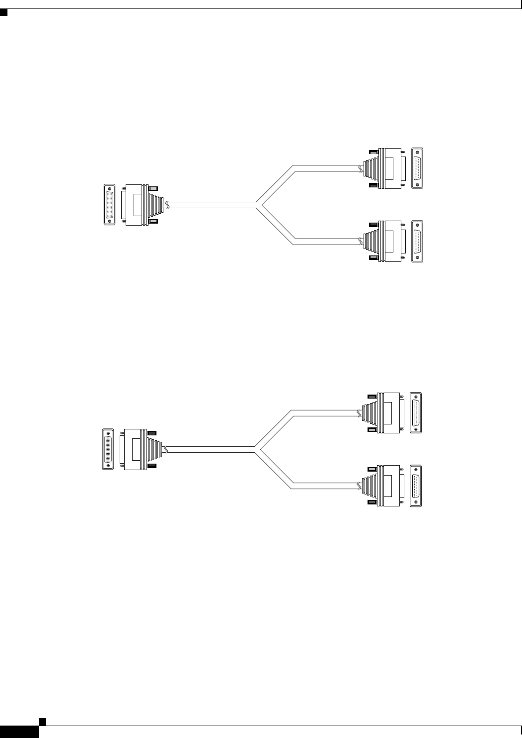
EIA530/RS366-DTE
Figure 2-9 shows the EIA530/RS366-DTE cable.
Figure 2-9 EIA530/RS366-DTE Cable
EIA530/RS366-DTE-LOS
Figure 2-10 shows the EIA530/RS366-DTE-LOS cable.
Figure 2-10 EIA530/RS366-DTE-LOS Cable
157160
J1 Male (DB-60)
J2 Male (DB-25)
J3 Male (DB-25)
EIA-530 data
RS-366
signaling
157161
J1 Male (DB-60)
J2 Male (DB-25)
J3 Male (DB-25)
EIA-530 data
RS-366
signaling
2-18
Installation and Upgrade Guide for Cisco Unified Videoconferencing 3545 PRI Gateway and 3545 Serial Gateway Release 5.5
OL-14912-01
Chapter 2 Installing the Cisco Unified Videoconferencing 3545 Gateway
Serial Gateway Cable Connections and Pin-outs
EIA530A/RS366-DTE
Figure 2-11 shows the EIA530A/RS366-DTE cable.
Figure 2-11 EIA530A/RS366-DTE Cable
KIV7/RS366-DTE
Figure 2-12 shows the KIV7/RS366-DTE cable.
Figure 2-12 KIV7/RS366-DTE Cable
157162
J1 Male (DB-60)
J2 Male (DB-25)
J3 Male (DB-25)
EIA-530A data
RS-366
signaling
157172
J1 Male (DB-60)
J2 Male (DB-37)
J3 Male (DB-25)
KIV-7 data
RS-366
signaling
2-19
Installation and Upgrade Guide for Cisco Unified Videoconferencing 3545 PRI Gateway and 3545 Serial Gateway Release 5.5
OL-14912-01
Chapter 2 Installing the Cisco Unified Videoconferencing 3545 Gateway
Serial Gateway Cable Connections and Pin-outs
Physical Description of DCE Cables
This section describes the following DCE cables supplied with the Cisco Cisco Unified
Videoconferencing 3545 Serial Gateway:
•V.35/RS366-DCE, page 2-19
•EIA449/RS366-DCE, page 2-20
•EIA530/RS366-DCE, page 2-20
Note • The DB-25 connector provides the data interface for the EIA530/RS366-DCE cable.
•The DB-37 connector provides the data interface for the EIA449/RS366-DCE cable.
•The DB-25 connector provides the RS-366 signaling interface for all Serial Gateway cables.
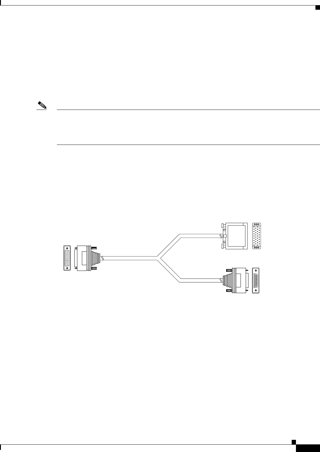
V.35/RS366-DCE
Figure 2-13 shows the V.35/RS366-DCE cable.
Figure 2-13 V.35/RS366-DCE Cable
157178
J1 Male (DB-60)
J2 Female
(M-34 Winchester)
J3 Female (DB-25)
V.35 data
RS-366
signaling

2-20
Installation and Upgrade Guide for Cisco Unified Videoconferencing 3545 PRI Gateway and 3545 Serial Gateway Release 5.5
OL-14912-01
Chapter 2 Installing the Cisco Unified Videoconferencing 3545 Gateway
Serial Gateway Cable Connections and Pin-outs
EIA449/RS366-DCE
Figure 2-14 shows the EIA449/RS366-DCE cable.
Figure 2-14 EIA449/RS366-DCE Cable
EIA530/RS366-DCE
Figure 2-15 shows the EIA530/RS366-DCE cable.
Figure 2-15 EIA530/RS366-DCE Cable
157157
J1 Male (DB-60)
J2 Female (DB-37)
J3 Female (DB-25)
EIA-449 data
RS-366
signaling
157159
J1 Male (DB-60)
J2 Female (DB-25)
J3 Female (DB-25)
EIA-530 data
RS-366
signaling

2-21
Installation and Upgrade Guide for Cisco Unified Videoconferencing 3545 PRI Gateway and 3545 Serial Gateway Release 5.5
OL-14912-01
Chapter 2 Installing the Cisco Unified Videoconferencing 3545 Gateway
Serial Gateway Cable Connections and Pin-outs
Data Interface Cable Pin-out Configurations
Table 2-7 describes the data interface pin-out configuration for the serial gateway cables.
Table 2-7 Serial Gateway Data Interface Cable Pin-out
Signal Name Mnemonic
KIV-7 (DB-37)
DTE only
EIA-449 (DB-37)
EIA-530 (DB-25)
EIA-530 LOS (DB-25)
DTE only
EIA-530A LOS (DB-25)
DTE only
V.35 (M-34)
Shield — 11111A
Transmit Data TXD A 24222P
Transmit Timing TXC A 15 5 15 15 15 Y
Receive Data RXD A 36333R
Request To Send RTS A 47444C
Receive Timing RXC A 17 8 17 17 17 V
Clear To Send CTS A 59555D
Data Set Ready DSR A 611666E
Data Terminal ready DTR A 2012202020H
Carrier Detect DCD A 813888F
Terminal Timing TT A 2417242424U
Signal Ground — 2719777B
Transmit Data TXD B 14 22 14 14 14 S
Transmit Timing TXC B 12 23 12 12 12 AA
Receive Data RXD B 1624161616T
Request To Send RTS B 1925191919—
Receive Timing RXC B 926999X
Clear To Send CTS B 1327131313—
Data Set Ready DSR B 22292222——
Data Terminal ready DTR B 23302323——
Carrier Detect DCD B 1031101010—
Terminal Timing TT B 1135111111W
Local Loopback LL — 10 18 — 18 L, K
Remote Loopback RLB — 14 21 — 21 N
Loss of Sync LOS unbalanced3136————
Loss of Sync LOS A — 3 — 18 — —
Loss of Sync LOS B — 21 — 21 — —
2-22
Installation and Upgrade Guide for Cisco Unified Videoconferencing 3545 PRI Gateway and 3545 Serial Gateway Release 5.5
OL-14912-01
Chapter 2 Installing the Cisco Unified Videoconferencing 3545 Gateway
Serial Gateway Cable Connections and Pin-outs
Data Interface Pin Layouts
This section illustrates the pin layouts for the serial gateway cable connectors.
M-34 Connector
Figure 2-16 shows the M-34 pin assignment.
Figure 2-16 M-34 Pin Layout
A
C
B
D
E
H
F
J
K
M
L
N
P
S
R
T
U
W
V
X
Y
AA
Z
BB
CC
EE
DD
FF
HH
KK
JJ
LL
MMNN
157173
2-23
Installation and Upgrade Guide for Cisco Unified Videoconferencing 3545 PRI Gateway and 3545 Serial Gateway Release 5.5
OL-14912-01
Chapter 2 Installing the Cisco Unified Videoconferencing 3545 Gateway
Serial Gateway Cable Connections and Pin-outs
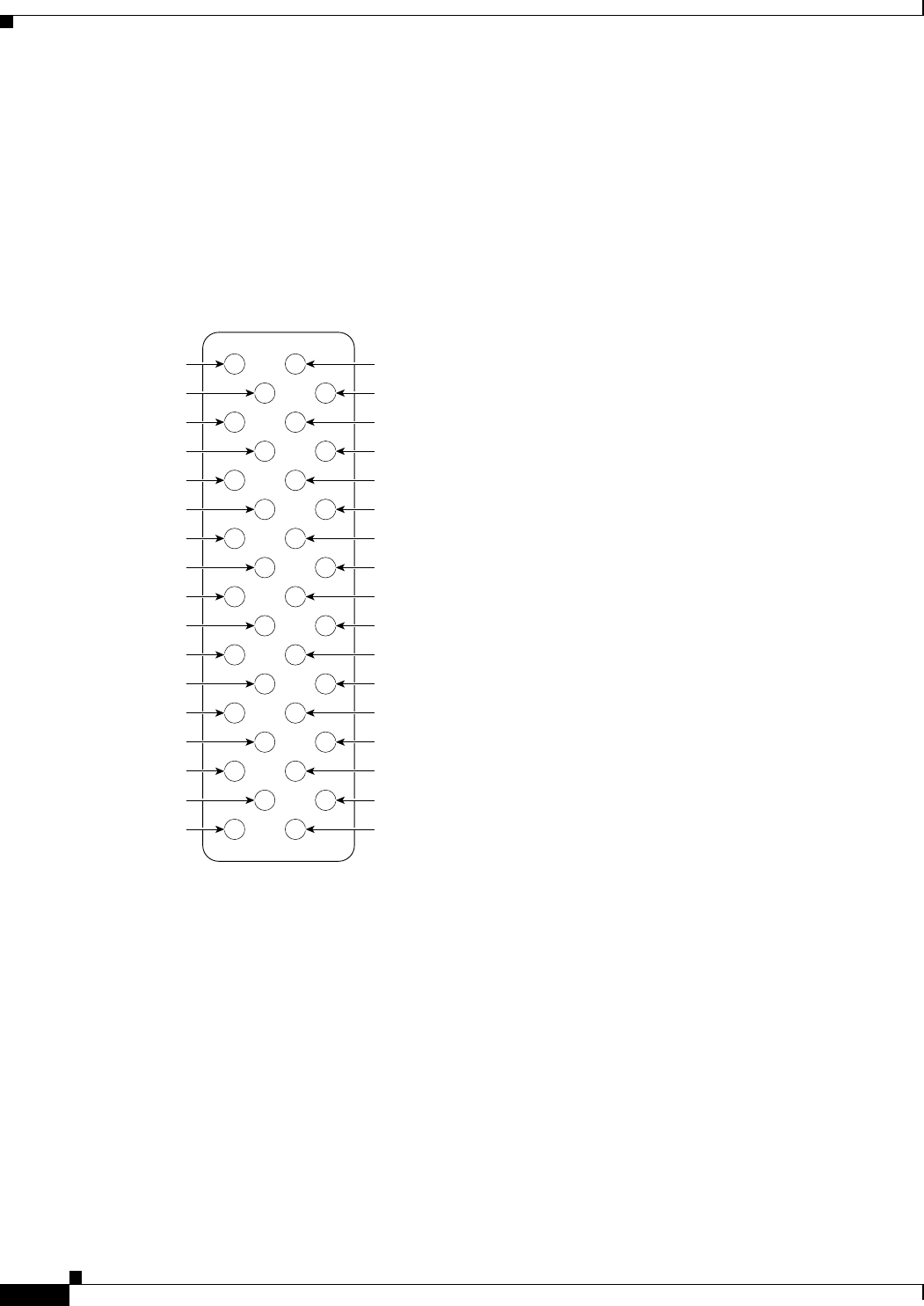
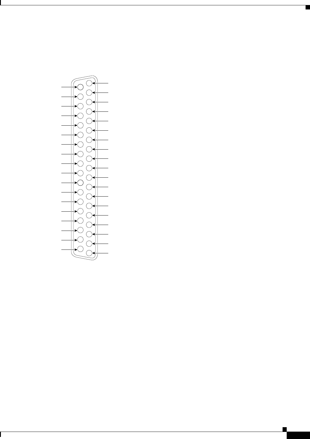
DB-37 Connector
Figure 2-17 shows the DB-37 pin layout.
Figure 2-17 DB-37 Pin Layout
1
20
21
22
23
24
25
26
27
28
29
30
31
32
33
34
35
36
37
2
3
4
5
6
7
8
9
10
11
12
13
14
15
16
17
18
19
157147
2-24
Installation and Upgrade Guide for Cisco Unified Videoconferencing 3545 PRI Gateway and 3545 Serial Gateway Release 5.5
OL-14912-01
Chapter 2 Installing the Cisco Unified Videoconferencing 3545 Gateway
Serial Gateway Cable Connections and Pin-outs
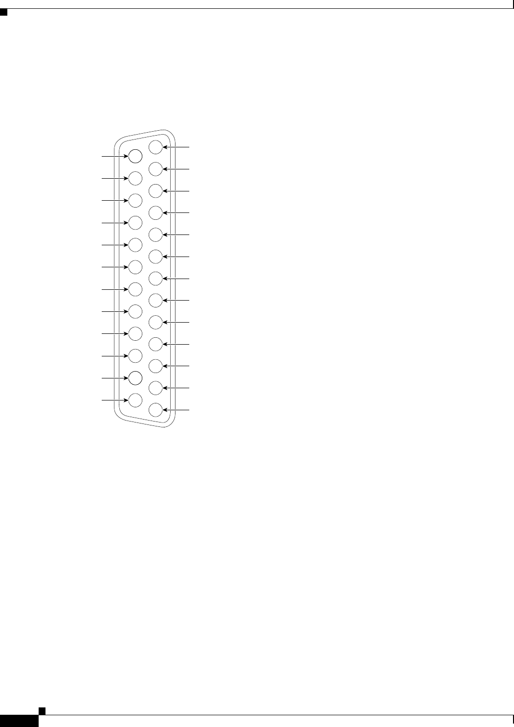
DB-25 Connector
Figure 2-18 shows the DB-25 pin layout.
Figure 2-18 DB-25 Pin Layout
1
14
15
16
17
18
19
20
21
22
23
24
25
2
3
4
5
6
7
8
9
10
11
12
13
157145

2-25
Installation and Upgrade Guide for Cisco Unified Videoconferencing 3545 PRI Gateway and 3545 Serial Gateway Release 5.5
OL-14912-01
Chapter 2 Installing the Cisco Unified Videoconferencing 3545 Gateway
Serial Gateway Cable Connections and Pin-outs
Signaling Interface Cable Pin-out Configuration
Table 2-8 describes the signaling interface pin-out configuration for the serial gateway cables.
Table 2-8 Serial Gateway Signaling Interface Cable Pin-out
Signal Name Mnemonic RS-366 (DB-25)
Shield — 1
Digit Present DPR 2
Abandon Call & Retry ACR 3
Call Request CRQ 4
Present Next Digit PND 5
Power Indication PWI 6
Signal Ground — 7
Distant Station
Connection
DSC 13
Digit Signal Circuit 1 NB1 14
Digit Signal Circuit 2 NB2 15
Digit Signal Circuit 4 NB4 16
Digit Signal Circuit 8 NB8 17
Receive Common RC 18
Send Common SC 19
Data Link Occupied DLO 22
2-26
Installation and Upgrade Guide for Cisco Unified Videoconferencing 3545 PRI Gateway and 3545 Serial Gateway Release 5.5
OL-14912-01
Chapter 2 Installing the Cisco Unified Videoconferencing 3545 Gateway
Serial Gateway Cable Connections and Pin-outs
Signaling Interface Pin Layout
This section illustrates the pin layout for the serial gateway signaling cable connector.
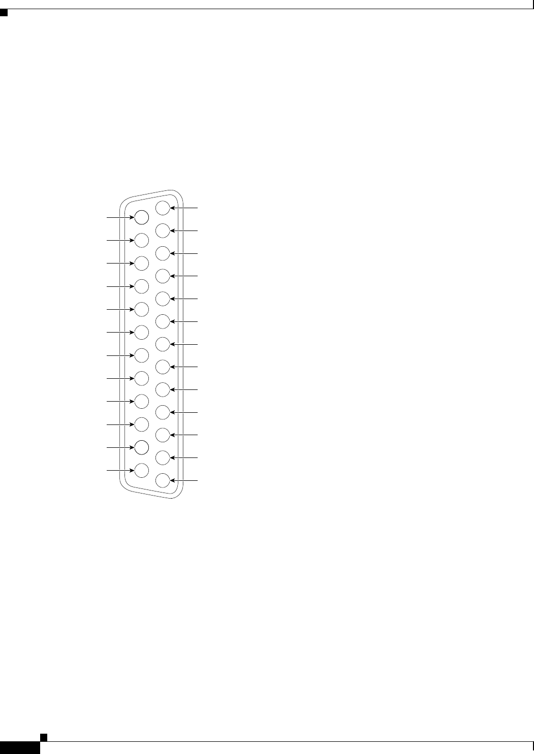
DB-25 Connector
Figure 2-19 shows the DB-25 pin layout.
Figure 2-19 DB-25 Pin Layout
1
14
15
16
17
18
19
20
21
22
23
24
25
2
3
4
5
6
7
8
9
10
11
12
13
157146

2-27
Installation and Upgrade Guide for Cisco Unified Videoconferencing 3545 PRI Gateway and 3545 Serial Gateway Release 5.5
OL-14912-01
Chapter 2 Installing the Cisco Unified Videoconferencing 3545 Gateway
Connecting the Gateway to a Power Source
Connecting the Gateway to a Power Source
This section describes how to supply power to the gateway. The gateway is equipped with an
autoswitching power supply that supports 100-240 VAC at 50/60 Hz.
Warning
Never defeat the ground conductor or operate the equipment in the absence of a suitably installed
ground conductor. Contact the appropriate electrical inspection authority or an electrician if you are
uncertain that suitable grounding is available.
Procedure
Step 1 Plug a power cord into the power socket on the rear panel of the gateway.
Step 2 Connect the power cable to a grounded AC outlet.
Step 3 Turn the power on.
Accessing the Gateway Administrator Interface
The Gateway Administrator is a web interface that allows you to view and configure the gateway
hardware and application parameters. You can use the gateway interface to:
•Set administrative parameters to define access to the gateway
•Set gateway application parameters that specify how the gateway processes incoming and outgoing
calls
•Set chassis operating parameters for Cisco Unified Videoconferencing 3545 Gateway modules
installed in the top slot of a Cisco Unified Videoconferencing 3545 chassis
Before You Begin
The following requirements are necessary to access the gateway Administrator web interface:
•A Java-compliant browser. Microsoft Internet Explorer version 5.5 or later is recommended.
•The gateway IP address or a web link to the gateway.
•Administrator level-access
•The required user name and password.
Note For first-time installation, you must assign an IP address to the gateway using a serial port connection
before you can access the web interface. For more information, see the “Setting the IP Address” section
on page 2-11.
Procedure
Step 1 Launch your browser and type the IP address or the name of the gateway.
For example, http://125.221.23.44 or board_name.

2-28
Installation and Upgrade Guide for Cisco Unified Videoconferencing 3545 PRI Gateway and 3545 Serial Gateway Release 5.5
OL-14912-01
Chapter 2 Installing the Cisco Unified Videoconferencing 3545 Gateway
Registering the Online Help
Step 2 Type the Administrator user name and password in the appropriate fields and click Login. The default
global user name is admin. The default password is <null>.
Note If you try to sign in as an Administrator and another Administrator is currently signed in, the gateway
signs you in as a Read only user and the words Read Only appear at the top of the window. Read only
users cannot edit any of the gateway settings.
Registering the Online Help
The online help files for the Cisco Unified Videoconferencing 3545 Gateway Administrator interface are
shipped on the Cisco Unified Videoconferencing Software CD-ROM. To use the online help, you must
install the help files for the appropriate Cisco Unified Videoconferencing 3545 Gateway in a shared
directory on your network and register the directory location in the Administrator interface.
If you wish to install the online help on a shared network location and link it to the Cisco Unified
Videoconferencing 3545 Gateway Administrator, see the document Installing Online Help for Cisco
Unified Videoconferencing 3500 Products.
Netscape Navigator Users
Online help files located on the local network and accessed using Netscape Navigator 4.x must be
located on a mapped network drive.

CHAPTER
3-1
Installation and Upgrade Guide for Cisco Unified Videoconferencing 3545 PRI Gateway and 3545 Serial Gateway Release 5.5
OL-14912-01
3
Using the Cisco Software Upgrade Utility
This section describes the following topics:
•Introduction, page 3-1
•Launching the Cisco Software Upgrade Utility, page 3-1
•Upgrading Software, page 3-2
Introduction
The Cisco Software Upgrade Utility is an interactive GUI interface that enables you to upgrade Cisco
software installed on Cisco devices.
The Cisco Software Upgrade Utility enables you to select files to be uploaded via a network or modem
connection to the Cisco device. You can select either to perform a typical upgrade which includes all the
new files or a customized upgrade which enables you to select which files to upload.
The upgrade files are uploaded and then burned into the memory of the Cisco device.
Before You Begin
Cisco devices automatically save configuration settings before a software upgrade takes place. However,
it is recommended that you save all configuration information using the Export button in the Cisco
device web interface toolbar. You can retrieve all these settings after the software upgrade is complete
by using the Import button in the Cisco device web interface toolbar.
Launching the Cisco Software Upgrade Utility
This section describes how to install and launch the Cisco Software Upgrade Utility.
Procedure
Step 1 Download the UpgradeUtility.exe file from the Cisco Unified Videoconferencing Software CD-ROM.
Step 2 Double click the UpgradeUtility.exe file to run the Software Upgrade Utility.
The upgrade files are extracted and the Upgrade Utility dialog box appears.

3-2
Installation and Upgrade Guide for Cisco Unified Videoconferencing 3545 PRI Gateway and 3545 Serial Gateway Release 5.5
OL-14912-01
Chapter 3 Using the Cisco Software Upgrade Utility
Upgrading Software
Upgrading Software
This section describes how to use the Software Upgrade Utility to upgrade Cisco software installed on
Cisco devices.
Procedure
Step 1 In the General Information section of the Upgrade Utility dialog box, enter the IP address of the device
you want to upgrade.
Step 2 In the Login Information section, enter the administrator user name and password for the target device,
as configured in the device network configuration settings.
Step 3 (Optional) Modify the read and write community settings for the target device as follows:
•Click Customize SNMP Settings.
The Customize SNMP Settings dialog box displays.
•Enter the required read community and write community values.
Note We recommend that you modify the default settings for security purposes.
•Click OK to return to the Upgrade Utility dialog box.
Step 4 (Optional) Select the components of the target device you want to upgrade as follows:
•Click Customize.
The Customize dialog box appears.
•Check the device components you want to upgrade in the Select the components you want to
upgrade list.
Note The components displayed vary according to the Cisco device upgraded.
•Click OK to return to the Upgrade Utility dialog box.
Step 5 Click Upgrade to upgrade all components of the Cisco device software (or only those components you
manually selected via the Customize option).
The Cisco Software Upgrade Utility informs you whether or not the upgrade is successful.
Note When the upgrade is complete, the Cisco device automatically resets itself and starts operation
with the new software version.

CHAPTER
4-1
Installation and Upgrade Guide for Cisco Unified Videoconferencing 3545 PRI Gateway and 3545 Serial Gateway Release 5.5
OL-14912-01
4
Cable Connections and Pin-outs
This section describes the following topics:
•Unit RS-232 9-Pin Serial Port, page 4-1
•9-Pin Serial Port Terminal Cable, page 4-2
•RJ-45 8-Pin IP Network Port, page 4-2
•Circuit Switch Network Port, page 4-3
•ISDN Port, page 4-3
Unit RS-232 9-Pin Serial Port
Table 4-1 describes the Cisco Unified Videoconferencing 3545 chassis RS-232 9-pin D-type serial port
pin-out configuration.
Table 4-1 RS-232 9-pin D-Type Serial Port Pin-out
Pin Function I/O
1NC
2RXDInput
3 TXD Output
4NC
5GND
6NC
7NC
8NC
9NC

4-2
Installation and Upgrade Guide for Cisco Unified Videoconferencing 3545 PRI Gateway and 3545 Serial Gateway Release 5.5
OL-14912-01
Chapter 4 Cable Connections and Pin-outs
9-Pin Serial Port Terminal Cable
9-Pin Serial Port Terminal Cable
Table 4-2 describes the pin-to-pin configuration of the RS-232 terminal cable provided with the
Cisco Unified Videoconferencing 3545 chassis.
RJ-45 8-Pin IP Network Port
Table 4-3 describes the pin-out configuration of the RJ-45 IP network port.
Table 4-2 S-232 Terminal Cable Pin-to-Pin Configuration
To Chassis
(DB-9 Male)
Function To PC Terminal (DB-9 Female)
2TXD3
3RXD2
5GND5
Table 4-3 Pin-out Configuration of the RJ-45 IP Network Port
Pin Function I/O
1 TXD+ Output
2 TXD+ Output
3 RXD+ Input
4NC
5NC
6 RXD- Input
7NC
8NC

4-3
Installation and Upgrade Guide for Cisco Unified Videoconferencing 3545 PRI Gateway and 3545 Serial Gateway Release 5.5
OL-14912-01
Chapter 4 Cable Connections and Pin-outs
Circuit Switch Network Port
Circuit Switch Network Port
Table 4-4 describes the circuit switch network port RJ-45 connector pin-out configuration.
ISDN Port
Table 4-5 describes the ISDN Port RJ-45 connector pin-out configuration.
Table 4-4 Circuit Switch Network Port RJ-45 Connector Pin-out
Pin Function
1RXD +
2RXD -
3NC
4 TXD +
5 TXD -
6NC
7NC
8NC
Table 4-5 ISDN Port RJ-45 Connector Pin-out
Pin Function
1RXD +
2RXD -
3NC
4 TXD +
5 TXD -
6NC
7NC
8NC

4-4
Installation and Upgrade Guide for Cisco Unified Videoconferencing 3545 PRI Gateway and 3545 Serial Gateway Release 5.5
OL-14912-01
Chapter 4 Cable Connections and Pin-outs
ISDN Port

CHAPTER
5-1
Installation and Upgrade Guide for Cisco Unified Videoconferencing 3545 PRI Gateway and 3545 Serial Gateway Release 5.5
OL-14912-01
5
Technical Specifications
This section provides technical specifications for the Cisco Unified Videoconferencing 3545 Chassis.
Technical Specifications Table
Table 5-1 Cisco Unified Videoconferencing 3545 Chassis Technical Specifications
Chassis Dimensions •Height: 2U (3.5 inches or 88.9 mm)
•Width: 17.25 inches (438.15 mm)
•Depth: 10 inches (254 mm)
•Weight: 8 kg (17.64 lbs) empty, 11 kg (24.25
lbs) full—may vary according to configuration
Element Board
Dimensions
•Width: 9.19 inches (233.35 mm)
•Depth: 6.3 inches (160 mm)
RTM Board
Dimensions
•Width: 9.19 inches (233.35 mm)
•Depth: 3.15 inches (80 mm)
System Monitoring LED
Indicators
•POWER
•ALARM
•FAN
•TEMP

5-2
Installation and Upgrade Guide for Cisco Unified Videoconferencing 3545 PRI Gateway and 3545 Serial Gateway Release 5.5
OL-14912-01
Chapter 5 Technical Specifications
Technical Specifications Table
Board LED Indicators
Front panel •ETHERNET:
•Link
•Connection Speed
•GK Reg
•CPU High (MCU only)
•CD (gateways only)
•ALARM
•ACT
•MC (EMP only)
Rear panel
(Cisco Unified
Videoconferencing
3545 PRI Gateway)
•PRI 1 or 2:
•ACT
•D-Ch
•ALRM
Rear panel
(Cisco Unified
Videoconferencing
3545 Serial Gateway)
•PORT 1 to 4:
•ACT
•ALARM
Push Buttons •RST (front panel)
Communication Interfaces
Front panel •Ethernet 10/100 Mbps auto-negotiate speed
select
•Asynchronous serial port RS-232 connected
via 9-pin D-type connector
Rear panel
(Cisco Unified
Videoconferencing
3545 PRI Gateway)
•2 x ISDN E1/T1 PRI port:
•T1 mode
Channels: 23B + 1D
Clock rate: 1.544 Mbps
Framing: F4, F12, ESF no CRC, ESF, F72
Encoding: NRZ, AMI-B7, B8ZS
Line impedance: 100Ω
•E1 mode
Channels: 30B + 1D
Clock rate: 2.048 Mbps
Framing: Double framing, CRC4,
Extended CRC4
Encoding: NRZ, CMI, AMI, HDB3
Line impedance: 120Ω
Table 5-1 Cisco Unified Videoconferencing 3545 Chassis Technical Specifications (continued)

5-3
Installation and Upgrade Guide for Cisco Unified Videoconferencing 3545 PRI Gateway and 3545 Serial Gateway Release 5.5
OL-14912-01
Chapter 5 Technical Specifications
Technical Specifications Table
Rear panel
(Cisco Unified
Videoconferencing
3545 Serial Gateway)
•4 x serial ports
Chipset •PowerPC MPC7410 32-bit RISC
microprocessor running at 500MHz.
•MPC8260 communication processor running at
300/200MHz.
Operating System •RTOS, VxWorks 5.4
Memory •32 MB on-board flash memory for field
upgrades
•2 MB L-2 Cache at 250MHz
•128 MB SDRAM
Failsafe •Watchdog timer built in
Power supply •Dual power supply units
•Full redundancy
•Power on/alarm LED on each unit.
•Input 100-240VAC, 50/60Hz, autoswitched
•Output + 3.3VDC, + 5VDC, ± 12VDC
•Maximum power load 300W
Ventilation Fans •2 fan units
•Brushless 12V DC motor
•Locked rotor detection
•Polarity protection
•Auto-restart capability
Table 5-1 Cisco Unified Videoconferencing 3545 Chassis Technical Specifications (continued)

5-4
Installation and Upgrade Guide for Cisco Unified Videoconferencing 3545 PRI Gateway and 3545 Serial Gateway Release 5.5
OL-14912-01
Chapter 5 Technical Specifications
Technical Specifications Table

CHAPTER
6-1
Installation and Upgrade Guide for Cisco Unified Videoconferencing 3545 PRI Gateway and 3545 Serial Gateway Release 5.5
OL-14912-01
6
Safety
This section describes the following topics:
•Electrical Safety, page 6-1
•ESD Procedures, page 6-2
Electrical Safety
To avoid an electric shock or damage to the Cisco Unified Videoconferencing 3545 System, servicing
should be performed by qualified service personnel only.
To reduce the risk of damaging power surges, Cisco recommends installing an AC surge arrestor in the
AC outlet from which the Cisco Unified Videoconferencing 3545 System is powered.
Warning
Changes or modifications to the device that are not approved by the party responsible for compliance
could void the user’s authority to operate the equipment.
Warning
There is a danger of explosion if the cPCI board battery is incorrectly replaced. Replace with the same
type, or an equivalent type recommended by the manufacturer. Dispose of used batteries only
according to manufacturer instructions.
Grounding
The power cable of the Cisco Unified Videoconferencing 3545 System should only be connected to a
power outlet that has a protective earth contact. Do not use an extension cord that does not have a
protective conductor (ground). The Cisco Unified Videoconferencing 3545 chassis can become
dangerous if you interrupt any of the protective conductors (grounding) or disconnect any of the
protective earth terminals.
Caution For North American installations, select a 3-conductor (18 AWG) power supply cord that is UL listed
and CSA certified. The cord must be terminated in a molded-on plug cap rated 125V/5A, with a
minimum length of 1.5m (6 feet) and no longer than 4.5m (approximately 14 feet).

6-2
Installation and Upgrade Guide for Cisco Unified Videoconferencing 3545 PRI Gateway and 3545 Serial Gateway Release 5.5
OL-14912-01
Chapter 6 Safety
ESD Procedures
Caution This is a class I unit. In Denmark, use this unit with an AC cord suited to Danish specifications. The cord
should include an earthing conductor. Plug the unit into a wall socket outlet which is connected to the
protective earth contact. Do not use socket outlets which are not connected to a protective earth contact!
Laite on liitettävä suojamaadoituskoskettimilla varustettuun pistorasiaan.
Apparatet må tilkoples jordet stikkontakt.
Apparaten skall anslutas till jordat uttag.
High Voltage
Disconnect the Cisco Unified Videoconferencing 3545 chassis from the power line before removing the
cover. Avoid any adjustment, maintenance, or repair of an opened chassis under voltage. These actions
should only be carried out by a skilled person who is aware of the dangers involved. Capacitors inside
the chassis may still be charged, even if the unit has been disconnected from the power source.
Power Supply
Caution Risk of electric shock and energy hazard. Disconnecting one power supply disconnects only one power
supply module. To isolate the unit completely, disconnect all power supplies.
ESD Procedures
To prevent damage to Cisco element boards by random electrostatic discharge (ESD), the use of wrist
straps is highly recommended.

6-3
Installation and Upgrade Guide for Cisco Unified Videoconferencing 3545 PRI Gateway and 3545 Serial Gateway Release 5.5
OL-14912-01
Chapter 6 Sicherheit
Elektrische Sicherheit
Sicherheit
Dieses Kapitel beschreibt die Sicherheitsvorschriften und -vorgaben zur Bedienung der Cisco Unified
Videoconferencing 3545-Plattform einschließlich des Folgenden:
•Elektrische Sicherheit, page 6-3
•ESD-Verfahren, page 6-4
•Warnhinweise, page 6-4
Elektrische Sicherheit
Zur Vermeidung eines elektrischen Schlags oder Schäden an der Cisco Unified Videoconferencing
3545-Plattform darf die Wartung von qualifiziertem Fachpersonal vorgenommen werden.
Cisco empfiehlt zur Minderung des Risikos von Stromstößen die Installation eines Stromableiters in der
Stromquelle, aus der die Cisco Unified Videoconferencing 3545 gespeist wird.
Erdung
Das Stromkabel der Cisco Unified Videoconferencing 3545 Plattform darf nur an Stromquellen
angeschlossen werden, die einen sch?tzenden Erdkontakt aufweisen. Keine Verlängerungsschnur
verwenden, die keinen Schutzleiter (Erdung) aufweisen. Das Cisco Unified Videoconferencing 3545
Gehäuse kann gefährlich werden, wenn einer der Schutzleiter (Erdung) unterbrochen oder einer der
schützenden Erdungskontakte abgeklemmt wird.
Hochspannung
Das Cisco Unified Videoconferencing 3545 Gehäuse vom Stromnetz nehmen, bevor die Abdeckung
entfernt wird. Anpassungen, Wartung oder Reparaturen eines geöffneten Gehäuses unter Spannung
vermeiden. Diese Tätigkeiten dürfen nur von einer qualifizierten Person durchgeführt werden, die sich
der Gefahren bewusst ist. Kondensatoren im Gehäuse können immer noch geladen sein, selbst wenn das
Gerät bereits vom Stromnetz genommen wurde.
Netzteil
Gafahr des elektrischen Schocks. Enterfernen des Netzsteckers eines Netzteils spannungsfrei Um alle
Einheiten spannungsfrei zu machen, sind die Netzstecker aller Netzteile zu entfernen.

6-4
Installation and Upgrade Guide for Cisco Unified Videoconferencing 3545 PRI Gateway and 3545 Serial Gateway Release 5.5
OL-14912-01
Chapter 6 Sicherheit
ESD-Verfahren
ESD-Verfahren
Zur Vermeidung von Beschädigungen der Cisco Einsatzelemente durch zufällige elektrostatische
Entladungen (ESD) wird die Verwendung von Schlaufen sehr empfohlen.
Warnhinweise
•Änderungen oder Modifikationen, die von der für die Einhaltung verantwortlichen Partei nicht
ausdrücklich genehmigt sind, können die Erlaubnis zur Nutzung des Geräts durch den Benutzer
unwirksam machen.
•Es besteht Explosionsgefahr, wenn die cPCI Steckbatterie nicht richtig eingesetzt wird. Durch
denselben oder einen gleichwertigen, vom Hersteller empfohlenen Typersetzen. Entsorgung
gebrauchter Batterien nur gemäß der Herstelleranweisungen.
•Die Stromversorgung darf nur von qualifiziertem Fachpersonal ersetzt werden.

6-5
Installation and Upgrade Guide for Cisco Unified Videoconferencing 3545 PRI Gateway and 3545 Serial Gateway Release 5.5
OL-14912-01
Chapter 6 Seguridad
Seguridad Electrica
Seguridad
Seguridad Electrica
Para prevenir un choque eléctrico o dañar la plataforma Cisco Unified Videoconferencing 3545, los
servicios deben ser hechos solamente por personal de servicios calificados.
Para reducir el riesgo de daño por picos de voltaje, Cisco recomienda la instalación de un supresor de
voltaje para corriente alterna AC en el circuito del tomacorriente para la plataforma Cisco Unified
Videoconferencing 3545.
•Cambios o modificaciones al dispositivo que no son aprobados por el grupo responsable de su
cumplimiento podría invalidar la autoridad del usuario para operar el equipo.
•Existe el peligro de explosión si la batería de la tarjeta cPCI es incorrectamente reemplazada.
Reempla cela con una del mismo tipo, o con una equivalente y recomendada por el fabricante.
Desechar las baterías usadas solamente de acuerdo a las instrucciones del fabricante.
r
Tierra
El cable eléctrico de energia para la plataforma Cisco Unified Videoconferencing 3545 debe ser
conectado solamente a un receptáculo de enchufe que tiene un contacto protector a tierra. No utilize un
cable de extensión sin un conductor protector a tierra. El chasis de la Cisco Unified Videoconferencing
3545 puede ser muy peligroso si usted interrumpe cualquiera de los conductores protectores a tierra, o
si usted desconecta cualquiera de los terminales protectores a tierra.
Alto Voltage
Desconecte el chasis Cisco Unified Videoconferencing 3545 de la fuente de suministro de energia antes
de remover la tapa. Evite hacer ajustes, mantenimiento o reparar un chasis abierto y encendido. Estas
acciones pueden ser hechas solamente por una persona calificada que está conciente de los potenciales
peligros. Capacitores dentro del chasis pueden todavía estar cargados, incluso cuando la unidad ha sido
desconectada de la fuente de suministro de energia.
Abastecimiento de Electricidad
Para evitar peligro de golpe eléctrico. Desconectando un solo abastecimiento eléctrico desconectara un
solo modulo. Para evitar contacto eléctrico de toda la unidad debe desconectar todos los abastecimientos
eléctricos.

6-6
Installation and Upgrade Guide for Cisco Unified Videoconferencing 3545 PRI Gateway and 3545 Serial Gateway Release 5.5
OL-14912-01
Chapter 6 Seguridad
Procedimientos ESD
Procedimientos ESD
Para prevenir daño a las tarjetas elementos de Cisco por descargas electrostáticas aleatorias (ESD), el
uso de bandas conductoras para descarga en la muñeca de los operadores en el área es altamente
recomendado.

6-7
Installation and Upgrade Guide for Cisco Unified Videoconferencing 3545 PRI Gateway and 3545 Serial Gateway Release 5.5
OL-14912-01
Chapter 6 Securite
Securite Electrique
Securite
Cette section décrit les procédures et les exigences en matière de sécurité concernant la mise en
exploitation de la Cisco Unified Videoconferencing 3545 System. Les sujets suivants y sont en
particulier abordés:
•Sécurité Électrique
•Prevention des Décharges Électrostatiques
Securite Electrique
Afin de prévenir tout risque d’électrocution ou de détérioration de la Cisco Unified
Videoconferencing 3545 System, l’entretien doit être effectué exclusivement par des techniciens de
maintenance qualifiés.
Afin de réduire le risque de dommages occasionnés par les surtensions électriques, Cisco recommande
de brancher un parasurtenseur dans la prise électrique à partir de laquelle la Cisco Unified
Videoconferencing 3545 System sera alimentée.
•Apporter des changements ou modifications à l’équipement sans avoir obtenu l’approbation de
l’entité responsable de la conformité peut annuler l’autorisation d’utilisation de l’équipement dont
bénéficie l’utilisateur.
•Il y a risque d’explosion si la batterie de la carte cPCI n’est pas remplacée correctement. Remplacer
par une pile de même type, ou d’un type équivalent recommandé par le fabricant. Ne se débarrasser
des piles usagées qu’en suivant les instructions du fabricant.
Mise a la Terre
Le câble d’alimentation électrique de la Cisco Unified Videoconferencing 3545 System doit être
connecté uniquement à une prise électrique reliée à une prise de terre. N’utilisez pas de rallonge ne
possédant pas de conducteur de protection (terre). Le Cisco Unified Videoconferencing 3545 chassis
peut présenter un danger si vous coupez l’un quelconque des conducteurs de protection (terre) ou
déconnectez l'un quelconque des équipements terminaux de mise à la terre.
Le connecteur de terre externe doit toujours être relié au circuit de prise de terre.
•Pour les installations d’Amérique du Nord, sélectionnez un cordon d’alimentation électrique à trois
conducteurs (18 AWG) bénéficiant d’une inscription UL et certifié CSA. Le cordon doit être terminé
par un connecteur moulé et autoriser une intensité de 5 A en 125V; sa longueur doit être comprise
entre 1,5 m et 4,5 m.
•Cette unité est de classe I. Au Danemark, utilisez cette unité avec un cordon d’alimentation
électrique conforme aux spécifications danoises. Le cordon électrique doit comporter un conducteur
de terre. Branchez l’unité sur une prise électrique murale reliée à la prise de terre. N’utilisez pas de
prise électrique non connectée à une prise de terre!

6-8
Installation and Upgrade Guide for Cisco Unified Videoconferencing 3545 PRI Gateway and 3545 Serial Gateway Release 5.5
OL-14912-01
Chapter 6 Securite
Prevention des Decharges Electrostatiques
•En Suède et en Finlande, l’installation ne doit se faire que dans des zones à accès contrôlé.
Haute Tension
Débranchez le Cisco Unified Videoconferencing 3545 chassis de la prise électrique avant d’enlever le
couvercle. Évitez toute intervention, opération d’entretien ou réparation sur un châssis ouvert sous
tension. Ces actions ne devraient être effectuées que par une personne expérimentée et connaissant les
dangers encourus. Certains condensateurs à l’intérieur du châssis peuvent être encore chargés, même
après que l’unité a été déconnectée de la source électrique.
Alimentation Electrique
Risque d’électrocution et autres dangers liés à l’électricité. Débrancher un câble d’alimentation ne
déconnecte qu’un seul module d’alimentation électrique. Pour isoler complètement l’unité, vous devez
déconnecter tous les câbles d’alimentation électrique.
Prevention des Decharges Electrostatiques
Afin d’éviter d’endommager les composants des cartes Cisco par suite de décharges électrostatiques
imprévues, il est vivement recommandé de porter un bracelet électrostatique.

CHAPTER
7-1
Installation and Upgrade Guide for Cisco Unified Videoconferencing 3545 PRI Gateway and 3545 Serial Gateway Release 5.5
OL-14912-01
7
Compliance and Certifications
This section describes the following topics:
•Safety Compliance, page 7-1
•EMC, page 7-2
•Telecom, page 7-2
•Environmental Compliance, page 7-4
Safety Compliance
This section lists the safety standards supported by the Cisco Unified Videoconferencing 3545 System.
•UL 60950
•CSA C22.2 No. 60950
•EN 60950
•TS 001
•AS/NZS 60950
•IEC 60950

7-2
Installation and Upgrade Guide for Cisco Unified Videoconferencing 3545 PRI Gateway and 3545 Serial Gateway Release 5.5
OL-14912-01
Chapter 7 Compliance and Certifications
EMC
EMC
This section lists the EMC compliance for the Cisco Unified Videoconferencing 3545 System.
•FCC Part 15 (CFR 47) Class A
•ICES-003 Class A
•EN 55022 Class A
•CISPR22 Class A
•AS/NZS CISPR22 Class A
•VCCI Class A
•CISPR24
•EN 55024
•EN 50082-1
•EN 61000-3-2
•EN 61000-3-3
•EN 61000-6-1
Warning
This is a class A product. In a domestic environment this product may cause radio interference in
which case the user may be required to take adequate measures.
FCC Part 15 Notice
This section provides RF interference information for the user.
This equipment has been tested and found to comply with the limits for a Class A digital device, pursuant
to Part 15 of the FCC rules. These limits are designed to provide reasonable protection against harmful
interference when the equipment is operated in a commercial environment. This equipment generates,
uses, and can radiate radio frequency energy and, if not installed and used in accordance with the
instruction manual, may cause harmful interference to radio communications. Operation of this
equipment in a residential area is likely to cause harmful interference, in which case the user will be
required to correct the interference at one’s own expense.
Warning
Changes or modifications to the device that are not approved by the party responsible for compliance
could void the user’s authority to operate the equipment.
Telecom
This section lists standards compliance for products that connect to ISDN lines.
•Administrative Council for Terminal Attachments (ACTA) Customer Information.
•Canadian Department of Communications Notice.
•CE CTR3
•CE CTR4

7-3
Installation and Upgrade Guide for Cisco Unified Videoconferencing 3545 PRI Gateway and 3545 Serial Gateway Release 5.5
OL-14912-01
Chapter 7 Compliance and Certifications
Telecom
ACTA Customer Information
Step 1 This equipment complies with Part 68 of the FCC rules, and the requirement adopted by the ACTA. On
the cover of this equipment is a label that contains, among other information, a product identifier in the
format US:AAAEQ##TXXXX, made out to CLPISR-45023-DW-N. If requested, this information must
be provided to the telephone company.
Step 2 Applicable registration jack USOCs (Universal Service Order Codes) for the equipment is RJ48C.
Step 3 A plug and jack used to connect this equipment to the premises wiring and telephone network must
comply with the applicable FCC Part 68 rules and requirements adopted by the ACTA. A compliant
telephone cord and modular plug is provided with this product. It is designed to be connected to a
compatible modular jack that is also compliant. See Installation Instructions for details.
Step 4 If the Cisco Unified Videoconferencing 3545 System equipment causes harm to the telephone network,
the telephone company will notify you in advance that temporary discontinuance of service may be
required. But if advance notice is not practical, the telephone company will notify the customer as soon
as possible. Also, you will be advised of your right to file a complaint with the FCC if you believe it is
necessary.
Step 5 The telephone company may make changes in its facilities, equipment, operations or procedures that
could affect the operation of the equipment. If this happens, the telephone company will provide advance
notice in order for you to make necessary modifications to maintain uninterrupted service.
Step 6 If trouble is experienced with the Cisco Unified Videoconferencing 3545 System equipment, for repairs
or warranty information please contact your Cisco representative for information on service or repairs.
If the equipment is causing harm to the telephone network, the telephone company may request that you
disconnect the equipment until the problem is resolved.
Step 7 Only Cisco Systems, Inc. qualified service personnel may repair the equipment.
Canadian Department of Communications Notice
The Canadian Department of Communications label identifies certified equipment. This certification
means that the equipment meets certain telecommunications network protective, operational and safety
requirements. The Department does not guarantee the equipment will operate to the user's satisfaction.
Before installing this equipment, users should ensure that it is permissible to be connected to the
facilities of the local telecommunications company. The equipment must also be installed using an
acceptable method of connection. In some cases, the company's inside wiring associated with a single
line individual service may be extended by means of a certified connector assembly (telephone extension
cord). The customer should be aware that compliance with the above condition may not prevent
degradation of service in some situations.
Repairs to some certified equipment should be made by an authorized maintenance facility designated
by the supplier. Any repairs or alterations made by the user to this equipment, or equipment
malfunctions, may give the telecommunications company cause to request the user to disconnect the
equipment.

7-4
Installation and Upgrade Guide for Cisco Unified Videoconferencing 3545 PRI Gateway and 3545 Serial Gateway Release 5.5
OL-14912-01
Chapter 7 Compliance and Certifications
Environmental Compliance
Users should ensure for their own protection that the ground connections of the power utility, telephone
lines and internal metallic water pipe platform, are connected together. This precaution may be
particularly important in rural areas.
Warning
Users should not attempt to make such connections themselves, but should contact the appropriate
E1/T1/PRI electric inspection authority, or appropriate E1/T1/PRI electrician.
Environmental Compliance
Cisco complies with the following EU Directives:
•Restrictions on the Use of Hazardous Substances (RoHS) Directive 2002/95/EC
•Waste Electrical and Electronic Equipment (WEEE) Directive 2002/96/EC

IN-1
Installation and Upgrade Guide for Cisco Unified Videoconferencing 3545 PRI Gateway and 3545 Serial Gateway Release 5.5
OL-14912-01
INDEX
A
access control 1-3
ACT LED 2-2, 2-3
Administrator interface 2-27
ALRM LED 2-2, 2-3
audio codecs 1-4
audio transcoding 1-4
auto-boot 2-10
autoswitching power supply 2-27
B
bandwidth
call overhead 1-13
resource allocation 1-14
supported 1-5
bonding
calls 1-6
boot configuration menu 2-10
C
cables
DCE 2-15
DTE 2-15
EIA449/RS366-DCE 2-20
EIA449/RS366-DTE 2-16
EIA530/RS366-DCE 2-20
EIA530/RS366-DTE 2-17
EIA530/RS366-DTE-LOS 2-17
EIA530A/RS366-DTE 2-18
KIV7/RS366-DTE 2-18
RJ-45 8-pin IP network port 4-2
RS-232 9-pin serial port 4-1
V.35/RS366-DCE 2-19
V.35/RS366-DTE 2-16
call bandwidth overhead 1-13
call handling
capabilities 1-5
PRI gateway capacity 1-13
CD LED 2-2
Certifications
EMC 7-2
Telecom 7-2
chassis dimensions 5-1
chipset 5-3
communication interfaces 5-2
conceal caller ID 1-3
connectors
Ethernet 2-2
PORT 2-3
PRI line 2-3
serial 2-2
D
data collaboration 1-2
DB-60 2-3
DB-9 1-5, 2-2
D-Ch LED 2-2
default extension 1-2
diagnostics 1-2
dial plan 1-2
DID 1-2
direct dialing 1-2

Index
IN-2
Installation and Upgrade Guide for Cisco Unified Videoconferencing 3545 PRI Gateway and 3545 Serial Gateway Release 5.5
OL-14912-01
downspeeding 1-3
DTMF 1-3
dual video 1-3
E
E1/T1 1-9, 1-14
EIA-530 2-14
element board dimensions 5-1
EMC 7-2
encryption 1-4
interoperability 1-6
serial gateway 1-11
via satellite 1-11
Ethernet
10/100Base-T 1-5
connector 2-2
Ethernet LED 2-2
F
failsafe 5-3
fast start 1-3
feature summary
general features 1-2
first-time installation 2-27
front panel 2-1
G
GK LED 2-2
H
H.239 1-3
H.243 1-4
H.323
fast start 1-3
hot swap 1-3
I
initial configuration 2-10
installation procedures
access Administrator interface 2-27
change default password 2-12
connect a serial cable 2-14
connect gateway to LAN 2-14
connect to a PC 2-10
connect to power supply 2-27
insert gateway in chassis 2-8
insert RTM in chassis 2-7
mount chassis on a 19-inch rack 2-5
set IP address 2-11
installation requirements 2-3
interoperability 1-2
IP address assign 2-11
IP network connection 1-4, 1-5
ISDN
connection failure 1-3
rollover 1-3
IVR 1-2
internal capacity 1-6
L
LAN 2-14
10/100Base-T 1-5
leased lines
serial gateway 1-12
LED indicators 2-2, 2-3
board 5-2
system monitoring 5-1
line quality 1-5

Index
IN-3
Installation and Upgrade Guide for Cisco Unified Videoconferencing 3545 PRI Gateway and 3545 Serial Gateway Release 5.5
OL-14912-01
M
media + signaling combinations 1-6
media protocols 1-5
memory 5-3
MSN 1-2
multimedia conferencing 1-7
multipoint conferencing 1-8
N
Netscape Navigator 2-28
network load balancing 1-2
Network Specific Facility (NSF) 1-3
O
online help 2-28
operating system 5-3
P
package contents 2-4
password
default login user 2-12
peer-to-peer
connectivity 1-4, 1-14
physical description
DCE cable 2-19
gateway module 2-1
Rear Transition Module (RTM) 2-2, 2-3
pin layout
DB-25 2-24, 2-26
DB-37 2-23
M-34 2-22
serial gateway cable connectors 2-22
serial gateway signaling cable connector 2-26
pin-out configuration
ISDN port RJ-45 connector 4-3
RJ-45 IP network port 4-2
RS-232 9-pin D-type serial port 4-1
serial gateway data interface cable 2-21
serial gateway signaling interface cable 2-25
pin-to-pin configuration
RS-232 terminal cable 4-2
point-to-point conferencing 1-8
PORT connectors 2-3
ports
RJ-45 IP 4-2
RS-232 9-pin serial 4-1
supported 1-4
power supply 2-27, 5-3
Prevention 6-8
PRI
call handling capacity 1-13
connecting gateway directly to central office
switch 1-10
connecting gateway to a PBX 1-10
interface features 1-6
ISDN connections 1-9
PRI LINE connector 2-3
push buttons 5-2
Q
Q.931 1-2
Quality of Service (QoS) 1-2
R
rack mounting 2-5
Rear Transition Module (RTM) 2-2, 2-3
requirements 2-11
installation 2-3
RJ-45 2-2, 2-3
rollover 1-3
routing 1-2

Index
IN-4
Installation and Upgrade Guide for Cisco Unified Videoconferencing 3545 PRI Gateway and 3545 Serial Gateway Release 5.5
OL-14912-01
RS-232
DTE 9-pin D-type connection 1-5
RS-449 2-14
RST button 2-2, 5-2
RTM board dimensions 5-1
RTM panel components 2-2, 2-3
S
Safety
compliance 7-1
electrical 6-1
ESD procedures 6-2
serial control port 1-5
serial lines 2-14
serial port connector 2-2
signaling protocols 1-5
SNMP
management 1-2
trap servers 1-3
software upgrade utility procedures
install and launch 3-1
use utility 3-2
SWAP RDY LED 2-2
switch information 1-6
T
T.120
data collaboration 1-2
TCS4 1-2
Telecom 7-2
top slot 2-6
U
upgrade software 3-1
V
V.35 2-14
video conferencing protocols 1-4
video protocols 1-4
video resolutions 1-5
W
web-based management 1-2
