Cisco Systems Prime Network 4 0 Users Manual User Guide, 4.0
49 8baa2e30-a721-4860-8dbb-9918686c8420 Cisco Systems Video Gaming Accessories 4 User Guide |
2015-01-05
: Cisco-Systems Cisco-Systems-Prime-Network-4-0-Users-Manual-203643 cisco-systems-prime-network-4-0-users-manual-203643 cisco-systems pdf
Open the PDF directly: View PDF ![]() .
.
Page Count: 1040 [warning: Documents this large are best viewed by clicking the View PDF Link!]
- Cisco Prime Network 4.0 User Guide
- Contents
- Preface
- Setting Up Devices and Using the GUI Clients
- Overview of the GUI Clients
- Setting Up Devices and Validating Device Information
- Configure Basic Device Settings: Name, DNS, NTP, RADIUS, TACACs, ACLs
- Configure SNMP and SNMP Traps on Device
- Configure Device Ports and Interfaces
- View Device and VRF Routing Tables and Device Interface Briefs
- Ping Destinations and VRFs, and View Trace Route from Device
- Change Device Syslog Logging Level
- View, Copy, and Overwrite Device Configuration Files
- View Users (Telnet Sessions) on Device
- Using Prime Network with Prime Central
- Working with the Prime Network Vision Client
- User Roles Required to Work with Basic Operations in Prime Network Vision
- Launching Prime Network Vision
- Changing Your GUI Client Password
- The Prime Network Vision Window
- Prime Network Vision Status Indicators
- Prime Network Vision Toolbar
- Prime Network Vision Menu Bar
- Prime Network Vision Right-Click Menus
- Adjusting the Prime Network Vision GUI Client Settings
- Filtering and Sorting Tabular Content
- Viewing and Managing NE Properties
- User Roles Required to Work with Prime Network Vision
- Information Available in Element Icons
- Viewing the Properties of a Network Element
- Inventory Window
- Checking VNE Connectivity and Communication Status
- Viewing the Physical Properties of a Device
- Working with Ports
- Viewing the Logical Properties of a Network Element
- Viewing Device Operating System Information
- Running an Activation from the Activation Menu
- Device Configurations and Software Images
- What is Change and Configuration Management?
- Set Up Change and Configuration Management
- Use the CCM Dashboard
- Device Configurations
- What is In the Archive?
- Protect Configurations in the Archive
- Editing an Archive Configuration
- Find Out What is Different Between Configurations
- Copy a Configuration File to a Central Server
- Are Running and Startup Configs Mismatched? (Cisco IOS and Cisco Nexus)
- Copy the Device Files to the Archive (Backups)
- Fix a Live Device Configuration (Restore)
- Clean Up the Archive
- Find Out What Changed on Live Devices
- Software Images
- Configuration Audit
- Compliance Audit
- Global Settings and Administration
- Working with Prime Network Vision Maps
- User Roles Required for Working with Prime Network Vision Maps
- Opening and Closing Maps
- Creating and Deleting Maps
- Adding and Removing NEs from Maps
- Managing Maps
- Finding NEs, Services, and Links, and Elements Affected by Tickets
- Working with Aggregations
- Working with Overlays
- Filtering Links in a Map
- Opening the CPU Usage Graph
- Communicating with Devices Using Ping and Telnet
- Working with Links
- Labeling NEs Using Business Tags
- Tracking Faults Using Prime Network Events
- Working with Tickets in Prime Network Vision
- Working with Reports
- Using Cisco PathTracer to Diagnose Problems
- User Roles Required to Work with Cisco PathTracer
- Cisco PathTracer Overview
- Launching Path Tracer
- Viewing Path Traces in Cisco PathTracer
- Viewing Path Trace Details
- Saving and Opening Cisco PathTracer Map Files
- Saving Cisco PathTracer Counter Values
- Rerunning a Path and Comparing Results
- Viewing Q-in-Q Path Information
- Viewing L2TP Path Information
- Using Cisco PathTracer in MPLS Networks
- Monitoring Carrier Ethernet Services
- User Roles Required to Work with Carrier Ethernet Services
- Viewing CDP Properties
- Viewing Link Layer Discovery Protocol Properties
- Viewing Spanning Tree Protocol Properties
- Viewing Resilient Ethernet Protocol Properties (REP)
- Viewing HSRP Properties
- Viewing Access Gateway Properties
- Working with Ethernet Link Aggregation Groups
- Viewing mLACP Properties
- Viewing Provider Backbone Bridge Properties
- Viewing EFP Properties
- Connecting a Network Element to an EFP
- Understanding EFP Severity and Ticket Badges
- Viewing EVC Service Properties
- Viewing and Renaming Ethernet Flow Domains
- Working with VLANs
- Understanding VLAN and EFD Discovery
- Understanding VLAN Elements
- Switching Entities Containing Termination Points
- Adding and Removing VLANs from a Map
- Viewing VLAN Mappings
- Working with Associated VLANs
- Viewing VLAN Links Between VLAN Elements and Devices
- Displaying VLANs By Applying VLAN Overlays to a Map45
- Viewing VLAN Service Link Properties
- Viewing REP Information in VLAN Domain Views and VLAN Overlays
- Viewing REP Properties for VLAN Service Links
- Viewing STP Information in VLAN Domain Views and VLAN Overlays
- Viewing STP Properties for VLAN Service Links
- Viewing VLAN Trunk Group Properties
- Viewing VLAN Bridge Properties
- Using Commands to Work With VLANs
- Understanding Unassociated Bridges
- Working with Ethernet Flow Point Cross-Connects
- Working with VPLS and H-VPLS Instances
- Working with Pseudowires
- Working with Ethernet Services
- Viewing IP SLA Responder Service Properties
- Viewing IS-IS Properties
- Viewing OSPF Properties
- Configuring REP and mLACP
- Using Pseudowire Ping and Show Commands
- Configuring IS-IS
- Monitoring Carrier Grade NAT Properties
- Monitoring DWDM Properties
- Monitoring Ethernet Operations, Administration, and Maintenance Tool Properties
- Monitoring Y.1731 IPSLA Configuration
- IPv6 and IPv6 VPN over MPLS
- Monitoring MPLS Services
- User Roles Required to Work with MPLS Networks
- Working with MPLS-TP Tunnels
- Viewing VPNs
- Managing VPNs
- Working with VPN Overlays
- Monitoring MPLS Services
- Viewing VPN Properties
- Viewing Site Properties
- Viewing VRF Properties
- Viewing VRF Egress and Ingress Adjacents
- Viewing Routing Entities
- Viewing Label Switched Entity Properties
- Multicast Label Switching (mLADP)
- Viewing MP-BGP Information
- Viewing 6rd Tunnel Properties
- Viewing BFD Session Properties
- Viewing Cross-VRF Routing Entries
- Viewing Pseudowire End-to-End Emulation Tunnels
- Viewing MPLS TE Tunnel Information
- Configuring VRF
- Configuring IP Interface
- Configuring MPLS-TP
- Configuring MPLS-TE
- Configuring MPLS
- Configuring RSVP
- Configuring BGP
- Configuring VRRP
- Configuring Bundle Ethernet
- Viewing IP and MPLS Multicast Configurations
- Monitoring MToP Services
- User Roles Required to Work with MToP
- Viewing SAToP Pseudowire Type in Logical Inventory
- Viewing CESoPSN Pseudowire Type in Logical Inventory
- Viewing Virtual Connection Properties
- Viewing IMA Group Properties
- Viewing TDM Properties
- Viewing Channelization Properties
- Viewing MLPPP Properties
- Viewing MLPPP Link Properties
- Viewing MPLS Pseudowire over GRE Properties
- Network Clock Service Overview
- Viewing CEM and Virtual CEM Properties
- Configuring SONET
- Configuring Clock
- Configuring TDM and Channelization
- Configuring Automatic Protection Switching (APS )
- Viewing and Managing SBCs
- Monitoring AAA Configurations
- Supported Network Protocols
- Viewing AAA Configurations in Prime Network Vision
- Viewing AAA Group Profile
- Viewing Dynamic Authorization Profile
- Viewing Radius Global Configuration Details
- Viewing AAA Group Configuration Details
- Viewing Diameter Configuration Details for an AAA Group
- Viewing Radius Configuration Details for an AAA Group
- Viewing Radius Accounting Configuration Details for an AAA Group
- Viewing the Radius Keepalive and Detect Dead Server Configuration Details for an AAA Group
- Viewing the Radius Authentication Configuration Details for an AAA Group
- Viewing the Charging Configuration Details for an AAA Group
- Viewing the Charging Trigger Configuration Details for an AAA Group
- Configuring AAA Groups
- Monitoring IP Pools
- Monitoring BNG Configurations
- Monitoring Mobile Technologies
- User Roles Required to Work with Mobile Technologies
- GPRS/UMTS Networks
- Overview of GPRS/UMTS Networks
- Working With GPRS/UMTS Network Technologies
- LTE Networks
- Overview of LTE Networks
- Working with LTE Network Technologies
- Monitoring System Architecture Evolution Networks (SAE-GW)
- Working with PDN-Gateways (P-GW)
- Working with Serving Gateway (S-GW)
- Viewing QoS Class Index to QoS (QCI-QoS) Mapping
- Viewing Layer 2 Tunnel Access Concentrator Configurations (LAC)
- Monitoring the HRPD Serving Gateway (HSGW)
- Monitoring Home Agent (HA)
- Monitoring the Foreign Agent (FA)
- Monitoring Evolved Packet Data Gateway (ePDG)
- Monitoring Packet Data Serving Node (PDSN)
- Viewing the Local Mobility Anchor Configuration (LMA)
- Scheduling 3GPP Inventory Retrieval Requests
- Viewing Operator Policies, APN Remaps, and APN Profiles
- Working with Active Charging Service
- Mobile Technologies Commands: Summary
- Monitoring the Mobility Management Entity
- Viewing the Stream Control Transmission Protocol
- Monitoring Data Center Configurations
- User Roles Required to Work with Data Center Configurations
- Virtual Port Channel (vPC)
- Cisco FabricPath
- Virtualization
- Viewing the Map Node for an UCS Network Element
- Viewing the Virtual Network Devices of a Data Center
- Viewing the Compute Server Support Details
- Viewing the Storage Area Network Support Details
- Searching for Compute Services
- Monitoring Cable Technologies
- Monitoring ADSL2+ and VDSL2 Technology Enhancements
- Icon and Button Reference
- Index

THE SPECIFICATIONS AND INFORMATION REGARDING THE PRODUCTS IN THIS MANUAL ARE SUBJECT TO CHANGE WITHOUT NOTICE. ALL
STATEMENTS, INFORMATION, AND RECOMMENDATIONS IN THIS MANUAL ARE BELIEVED TO BE ACCURATE BUT ARE PRESENTED WITHOUT
WARRANTY OF ANY KIND, EXPRESS OR IMPLIED. USERS MUST TAKE FULL RESPONSIBILITY FOR THEIR APPLICATION OF ANY PRODUCTS.
THE SOFTWARE LICENSE AND LIMITED WARRANTY FOR THE ACCOMPANYING PRODUCT ARE SET FORTH IN THE INFORMATION PACKET THAT
SHIPPED WITH THE PRODUCT AND ARE INCORPORATED HEREIN BY THIS REFERENCE. IF YOU ARE UNABLE TO LOCATE THE SOFTWARE LICENSE
OR LIMITED WARRANTY, CONTACT YOUR CISCO REPRESENTATIVE FOR A COPY.
The Cisco implementation of TCP header compression is an adaptation of a program developed by the University of California, Berkeley (UCB) as part of UCB’s public
domain version of the UNIX operating system. All rights reserved. Copyright © 1981, Regents of the University of California.
NOTWITHSTANDING ANY OTHER WARRANTY HEREIN, ALL DOCUMENT FILES AND SOFTWARE OF THESE SUPPLIERS ARE PROVIDED “AS IS” WITH
ALL FAULTS. CISCO AND THE ABOVE-NAMED SUPPLIERS DISCLAIM ALL WARRANTIES, EXPRESSED OR IMPLIED, INCLUDING, WITHOUT
LIMITATION, THOSE OF MERCHANTABILITY, FITNESS FOR A PARTICULAR PURPOSE AND NONINFRINGEMENT OR ARISING FROM A COURSE OF
DEALING, USAGE, OR TRADE PRACTICE.
IN NO EVENT SHALL CISCO OR ITS SUPPLIERS BE LIABLE FOR ANY INDIRECT, SPECIAL, CONSEQUENTIAL, OR INCIDENTAL DAMAGES, INCLUDING,
WITHOUT LIMITATION, LOST PROFITS OR LOSS OR DAMAGE TO DATA ARISING OUT OF THE USE OR INABILITY TO USE THIS MANUAL, EVEN IF CISCO
OR ITS SUPPLIERS HAVE BEEN ADVISED OF THE POSSIBILITY OF SUCH DAMAGES.
Cisco and the Cisco logo are trademarks or registered trademarks of Cisco and/or its affiliates in the U.S. and other countries. To view a list of Cisco trademarks, go to this
URL: www.cisco.com/go/trademarks. Third-party trademarks mentioned are the property of their respective owners. The use of the word partner does not imply a partnership
relationship between Cisco and any other company. (1110R)
Any Internet Protocol (IP) addresses and phone numbers used in this document are not intended to be actual addresses and phone numbers. Any examples, command display
output, network topology diagrams, and other figures included in the document are shown for illustrative purposes only. Any use of actual IP addresses or phone numbers in
illustrative content is unintentional and coincidental.
Cisco Prime Network 4.0 User Guide
© 1999-2013 Cisco Systems, Inc. All rights reserved.

iii
Cisco Prime Network 4.0 User Guide
OL-29343-01
CONTENTS
Preface xxiii
Audience xxiii
Document Organization xxiv
Conventions xxvi
Related Documentation xxvii
Obtaining Documentation and Submitting a Service Request xxvii
xxvii
CHAPTER
1Setting Up Devices and Using the GUI Clients 1-1
Overview of the GUI Clients 1-1
Prime Network Vision 1-2
Prime Network Events 1-3
Prime Network Administration 1-3
Prime Network Change and Configuration Management 1-3
Prime Network Operations Reports 1-3
Setting Up Devices and Validating Device Information 1-4
Configure Basic Device Settings: Name, DNS, NTP, RADIUS, TACACs, ACLs 1-5
Configure SNMP and SNMP Traps on Device 1-7
Configure Device Ports and Interfaces 1-7
View Device and VRF Routing Tables and Device Interface Briefs 1-9
Ping Destinations and VRFs, and View Trace Route from Device 1-9
Change Device Syslog Logging Level 1-9
View, Copy, and Overwrite Device Configuration Files 1-10
View Users (Telnet Sessions) on Device 1-10
Using Prime Network with Prime Central 1-10
CHAPTER
2Working with the Prime Network Vision Client 2-1
User Roles Required to Work with Basic Operations in Prime Network Vision 2-1
Launching Prime Network Vision 2-2
Changing Your GUI Client Password 2-4
The Prime Network Vision Window 2-4
Prime Network Vision Inventory Tabs 2-5
Prime Network Vision Maps 2-6

Contents
iv
Cisco Prime Network 4.0 User Guide OL-29343-01
Opening Maps 2-7
Navigation Pane 2-7
Content Pane: Map, List, and Links Views 2-8
Ticket Pane 2-17
Prime Network Vision Status Indicators 2-17
Severity 2-18
VNE Management States 2-19
Tickets 2-23
Prime Network Vision Toolbar 2-23
Prime Network Vision Menu Bar 2-25
File Menu 2-26
Edit Menu 2-27
View Menu 2-27
Node Menu 2-28
Tools Menu 2-28
Activation Menu 2-29
Network Inventory Menu 2-29
Reports Menu 2-30
Window Menu 2-30
Help Menu 2-30
Prime Network Vision Right-Click Menus 2-31
Map Right-Click Menu 2-32
Element Right-Click Menu 2-32
Aggregation Right-Click Menu 2-36
Link Right-Click Menu 2-36
List View Right-Click Menu 2-37
Links View Right-Click Menu 2-39
Ticket Right-Click Menu 2-40
Adjusting the Prime Network Vision GUI Client Settings 2-40
Filtering and Sorting Tabular Content 2-42
CHAPTER
3Viewing and Managing NE Properties 3-1
User Roles Required to Work with Prime Network Vision 3-1
Information Available in Element Icons 3-3
Viewing the Properties of a Network Element 3-6
Network Element Badges 3-8
Inventory Window 3-9
Navigation Pane 3-12

Contents
v
Cisco Prime Network 4.0 User Guide
OL-29343-01
Content Pane 3-13
Device View Pane 3-13
Device View Pane Toolbar 3-14
Ticket and Events Pane 3-15
Checking VNE Connectivity and Communication Status 3-16
Viewing the Physical Properties of a Device 3-19
Redundancy Support 3-21
Viewing Satellite Properties 3-22
Working with Ports 3-23
Viewing Port Status and Properties 3-23
Viewing a Port Configuration 3-25
Disabling and Enabling Alarms 3-26
Generating a Port Utilization Graph 3-27
Viewing the Logical Properties of a Network Element 3-27
Logical Inventory Window 3-28
Logical Inventory Navigation Pane Branches 3-29
Logical Inventory Navigation Pane Icons 3-30
Logical Inventory Content Pane Tabs 3-31
Viewing Device Operating System Information 3-31
Running an Activation from the Activation Menu 3-34
Network Activation Window 3-35
Running Activations 3-35
Searching for Activations (Activation History) 3-36
Rolling Back an Activation 3-36
Cloning an Existing Activation 3-37
Deleting Activations 3-37
CHAPTER
4Device Configurations and Software Images 4-1
What is Change and Configuration Management? 4-1
Set Up Change and Configuration Management 4-3
Prime Network Setup Tasks 4-3
Device Setup Tasks 4-4
Configuration Management Setup Tasks 4-5
NEIM Setup Tasks 4-7
Device Groups Setup Tasks 4-9
Use the CCM Dashboard 4-10
Device Configurations 4-12
What is In the Archive? 4-12

Contents
vi
Cisco Prime Network 4.0 User Guide OL-29343-01
Protect Configurations in the Archive 4-13
Editing an Archive Configuration 4-14
Find Out What is Different Between Configurations 4-14
Copy a Configuration File to a Central Server 4-16
Are Running and Startup Configs Mismatched? (Cisco IOS and Cisco Nexus) 4-17
Copy the Device Files to the Archive (Backups) 4-18
Fix a Live Device Configuration (Restore) 4-22
Clean Up the Archive 4-25
Find Out What Changed on Live Devices 4-25
Software Images 4-26
Add New Images to the Repository 4-27
New Devices: Create an Image Baseline 4-28
Distribute Images and Make Sure They Will Work 4-29
What is Upgrade Analysis? 4-30
Distribute Images to Devices 4-31
Activate Cisco IOS Software Images 4-34
Perform Cisco IOS XR Software Package Operations 4-37
Clean Up the Repository 4-44
Configuration Audit 4-45
Manage Configuration Policies 4-46
Schedule Configuration Audit 4-47
View Configuration Audit Jobs and Audit Results 4-48
Compliance Audit 4-50
User Authentication and Authorization 4-51
Creating Policies and Profiles, and Running a Compliance Audit Job 4-52
Creating a Policy 4-52
Creating a Policy Profile 4-57
Auditing Devices 4-58
Viewing the Results of an Audit Job and Running Fixes for Violations 4-59
Global Settings and Administration 4-61
Change Configuration Managemennt Global Settings 4-61
Change Image Management Global Settings 4-66
Check the Processes 4-68
Manage Jobs 4-68
User Authentication and Authorization 4-69
CHAPTER
5Working with Prime Network Vision Maps 5-1
User Roles Required for Working with Prime Network Vision Maps 5-2
Opening and Closing Maps 5-5

Contents
vii
Cisco Prime Network 4.0 User Guide
OL-29343-01
Creating and Deleting Maps 5-6
Creating New Maps 5-6
Deleting Maps from the Database 5-8
Adding and Removing NEs from Maps 5-9
Managing Maps 5-11
Selecting Map Viewing Options 5-12
Applying a Background Image 5-12
Using the Overview Window 5-14
Saving Maps 5-15
Finding NEs, Services, and Links, and Elements Affected by Tickets 5-15
Working with Aggregations 5-16
Grouping Network Elements into Aggregations 5-16
Viewing an Aggregation Thumbnail 5-16
Adding Elements to an Existing Aggregation 5-18
Ungrouping Aggregations 5-19
Viewing Multi-Chassis Devices 5-19
Viewing Inter Rack Links 5-20
Viewing Inter Chassis Links 5-20
Working with Overlays 5-21
Filtering Links in a Map 5-25
Opening the CPU Usage Graph 5-27
Communicating with Devices Using Ping and Telnet 5-28
CHAPTER
6Working with Links 6-1
User Roles Required to Work with Links 6-1
What Are Dynamic and Static Links? 6-3
Link Discovery and Flickering Ethernet Topology Links 6-3
Viewing Link Properties 6-4
Viewing Link Properties in Prime Network Vision Maps 6-4
Viewing Link Properties in the Links View 6-8
Viewing Link Properties in the Link Properties Window 6-10
Link List Pane 6-11
Properties Pane 6-11
Ticket and Events Pane 6-12
Viewing Link Impact Analysis 6-12
Adding Static Links 6-15
Filtering Links Using the Collection Method 6-17
Selecting a Link 6-18

Contents
viii
Cisco Prime Network 4.0 User Guide OL-29343-01
CHAPTER
7Labeling NEs Using Business Tags 7-1
User Roles Required to Work with Business Tags and Business Elements 7-1
Using Chinese Characters 7-2
Attaching and Detaching Business Tags 7-3
Searching for Business Tags and Viewing Their Properties 7-4
Renaming a Business Element 7-7
Deleting a Business Element 7-7
CHAPTER
8Tracking Faults Using Prime Network Events 8-1
User Roles Required to Work with Prime Network Events 8-1
Launching Prime Network Events 8-1
Setting Up Your Events View 8-2
Viewing Events and Tickets in Cisco Prime Network Events 8-2
Event Types and Categories 8-4
Audit Events 8-4
Provisioning Events 8-5
Security Events 8-5
System Events 8-6
Service Events 8-6
Syslogs 8-7
V1 Traps 8-7
V2 Traps 8-8
V3 Traps 8-8
Tickets 8-9
Working with Cisco Prime Network Events 8-10
Viewing Event Properties 8-10
Viewing Ticket Properties 8-14
Refreshing Cisco Prime Network Events Information 8-17
Filtering Events 8-18
Exporting Displayed Data 8-21
CHAPTER
9Working with Tickets in Prime Network Vision 9-1
What are Tickets? 9-1
User Roles Required to Work with Tickets in Prime Network Vision 9-2
Viewing Tickets and Network Events for Elements in a Map 9-3
Managing Tickets in the Tickets Tab 9-4
Filtering Tickets by Network Element 9-6
Filtering Tickets by Criteria 9-7

Contents
ix
Cisco Prime Network 4.0 User Guide
OL-29343-01
Viewing Ticket Properties 9-9
Details Tab 9-10
History Tab 9-11
Affected Parties Tab 9-11
Correlation Tab 9-13
Advanced Tab 9-13
Notes Tab 9-14
User Audit Tab 9-14
Managing Tickets 9-15
Impact Analysis in Prime Network 9-17
CHAPTER
10 Working with Reports 10-1
User Roles Required to Manage Reports 10-1
Using the Report Manager 10-4
Menu Options 10-6
Report Manager Toolbar 10-6
Navigation Tree 10-7
Content Pane 10-7
Reports Right-Click Options 10-9
Report Categories 10-11
Events Reports 10-11
Inventory Reports 10-18
Network Service Reports 10-20
Generating Reports 10-22
Database Load and Report Generation 10-22
Report Generation Failure 10-22
Report Generation Canceled 10-23
Generating Reports from Report Manager 10-23
Generating Events Reports 10-23
Generating Inventory Reports 10-31
Generating Network Service Reports 10-34
Generating Reports from the Reports Menu 10-37
Generating Reports from Prime Network Vision 10-38
Scheduling Reports 10-38
Managing Reports 10-39
Managing the Maximum Number of Concurrent Reports 10-39
Viewing and Saving Reports 10-40
Renaming Reports 10-41
Sharing Reports 10-42

Contents
x
Cisco Prime Network 4.0 User Guide OL-29343-01
Moving Reports Between Folders 10-43
Deleting Reports 10-43
Viewing Report Properties 10-44
Defining Report Types 10-45
Managing Report Folders 10-45
Creating Folders 10-45
Moving Folders 10-46
Renaming Folders 10-46
Deleting Folders 10-47
Viewing Folder and Report Type Properties 10-47
CHAPTER
11 Using Cisco PathTracer to Diagnose Problems 11-1
User Roles Required to Work with Cisco PathTracer 11-1
Cisco PathTracer Overview 11-2
Launching Path Tracer 11-3
Cisco PathTracer Right-Click Menu Options 11-4
Starting a Path Trace 11-5
From the Map View 11-5
From Logical or Physical Inventory 11-7
Examples of Launching Cisco PathTracer 11-7
Viewing Path Traces in Cisco PathTracer 11-14
Menus 11-16
Toolbar 11-17
Trace Tabs 11-18
Paths Pane 11-18
Path Trace Pane 11-18
Right-Click Menu Options 11-19
Viewing Path Trace Details 11-20
Menus 11-22
Cisco PathTracer Details Window Toolbar 11-22
Path Trace Pane 11-23
Details Pane 11-25
Saving and Opening Cisco PathTracer Map Files 11-26
Saving Cisco PathTracer Counter Values 11-26
Rerunning a Path and Comparing Results 11-27
Viewing Q-in-Q Path Information 11-27
Viewing L2TP Path Information 11-28
Using Cisco PathTracer in MPLS Networks 11-29

Contents
xi
Cisco Prime Network 4.0 User Guide
OL-29343-01
Cisco PathTracer MPLS Start and Endpoints 11-30
Using Cisco PathTracer for CSC Configurations 11-31
Using Cisco PathTracer for Layer 3 VPNs 11-32
Using Cisco PathTracer for Layer 2 VPNs 11-32
Using Cisco PathTracer for MPLS TE Tunnels 11-33
CHAPTER
12 Monitoring Carrier Ethernet Services 12-1
User Roles Required to Work with Carrier Ethernet Services 12-2
Viewing CDP Properties 12-6
Viewing Link Layer Discovery Protocol Properties 12-8
Viewing Spanning Tree Protocol Properties 12-10
Viewing Resilient Ethernet Protocol Properties (REP) 12-14
Viewing HSRP Properties 12-18
Viewing Access Gateway Properties 12-19
Working with Ethernet Link Aggregation Groups 12-23
Viewing Ethernet LAG Properties 12-23
Viewing mLACP Properties 12-29
Viewing Provider Backbone Bridge Properties 12-32
Viewing EFP Properties 12-33
Connecting a Network Element to an EFP 12-38
Understanding EFP Severity and Ticket Badges 12-38
Viewing EVC Service Properties 12-40
Viewing and Renaming Ethernet Flow Domains 12-42
Working with VLANs 12-45
Understanding VLAN and EFD Discovery 12-45
Understanding VLAN Elements 12-46
Switching Entities Containing Termination Points 12-50
Adding and Removing VLANs from a Map 12-50
Viewing VLAN Mappings 12-53
Working with Associated VLANs 12-55
Adding an Associated VLAN 12-55
Viewing Associated Network VLAN Service Links and VLAN Mapping Properties 12-57
Viewing VLAN Links Between VLAN Elements and Devices 12-58
Displaying VLANs By Applying VLAN Overlays to a Map45 12-61
Viewing VLAN Service Link Properties 12-63
Viewing REP Information in VLAN Domain Views and VLAN Overlays 12-63
Viewing REP Properties for VLAN Service Links 12-64
Viewing STP Information in VLAN Domain Views and VLAN Overlays 12-66

Contents
xii
Cisco Prime Network 4.0 User Guide OL-29343-01
Viewing STP Properties for VLAN Service Links 12-67
Viewing VLAN Trunk Group Properties 12-68
Viewing VLAN Bridge Properties 12-70
Using Commands to Work With VLANs 12-72
Understanding Unassociated Bridges 12-73
Adding Unassociated Bridges 12-73
Working with Ethernet Flow Point Cross-Connects 12-75
Adding EFP Cross-Connects 12-76
Viewing EFP Cross-Connect Properties 12-76
Working with VPLS and H-VPLS Instances 12-78
Adding VPLS Instances to a Map 12-79
Applying VPLS Instance Overlays 12-80
Viewing Pseudowire Tunnel Links in VPLS Overlays 12-82
Viewing VPLS-Related Properties 12-83
Viewing VPLS Instance Properties 12-84
Viewing Virtual Switching Instance Properties 12-85
Viewing VPLS Core or Access Pseudowire Endpoint Properties 12-87
Viewing VPLS Access Ethernet Flow Point Properties 12-89
Working with Pseudowires 12-90
Adding Pseudowires to a Map 12-90
Viewing Pseudowire Properties 12-93
Displaying Pseudowire Information 12-95
Viewing Pseudowire Redundancy Service Properties 12-96
Applying Pseudowire Overlays 12-98
Monitoring the Pseudowire Headend 12-100
Viewing the PW-HE configuration 12-102
Viewing PW-HE Configured as a Local Interface under Pseudowire 12-104
Viewing PW-HE Generic Interface List 12-105
Viewing PW-HE as an Associated Entity for a Routing Entity 12-105
Viewing PW-HE as an Associated Entity for a VRF 12-105
Working with Ethernet Services 12-106
Adding Ethernet Services to a Map 12-106
Applying Ethernet Service Overlays 12-108
Viewing Ethernet Service Properties 12-109
Viewing IP SLA Responder Service Properties 12-112
Viewing IS-IS Properties 12-114
Viewing OSPF Properties 12-117
Configuring REP and mLACP 12-119
Using Pseudowire Ping and Show Commands 12-120

Contents
xiii
Cisco Prime Network 4.0 User Guide
OL-29343-01
Configuring IS-IS 12-121
CHAPTER
13 Monitoring Carrier Grade NAT Properties 13-1
User Roles Required to View Carrier Grade NAT Properties 13-2
Viewing Carrier Grade NAT Properties in Logical Inventory 13-2
Viewing Carrier Grade NAT Properties in Physical Inventory 13-5
Configuring CG NAT Service 13-6
CHAPTER
14 Monitoring DWDM Properties 14-1
User Roles Required to View DWDM Properties 14-1
Viewing DWDM in Physical Inventory 14-3
Viewing G.709 Properties 14-5
Viewing Performance Monitoring Configuration 14-11
Configuring and Viewing DWDM 14-15
CHAPTER
15 Monitoring Ethernet Operations, Administration, and Maintenance Tool Properties 15-1
User Roles Required to View Ethernet OAM Tool Properties 15-1
Ethernet OAM Overview 15-2
Viewing Connectivity Fault Management Properties 15-3
Viewing Ethernet LMI Properties 15-10
Viewing Link OAM Properties 15-14
Configuring CFM 15-18
Configuring E-LMI 15-20
Configuring L-OAM 15-21
CHAPTER
16 Monitoring Y.1731 IPSLA Configuration 16-1
Y.1731 Technology: Overview 16-1
User Roles Required to Work with Y.1731 Probes 16-2
Working with Y.1731 IPSLA Configurations 16-2
Viewing Y.1731 Probe Properties 16-2
Configuring Y.1731 Probes 16-4
CHAPTER
17 IPv6 and IPv6 VPN over MPLS 17-1
User Roles Required to Work with IPv6 and 6VPE 17-2
Viewing IPv6 Information 17-2

Contents
xiv
Cisco Prime Network 4.0 User Guide OL-29343-01
CHAPTER
18 Monitoring MPLS Services 18-1
User Roles Required to Work with MPLS Networks 18-1
Working with MPLS-TP Tunnels 18-4
Adding an MPLS-TP Tunnel 18-5
Viewing MPLS-TP Tunnel Properties 18-7
Viewing LSPs Configured on an Ethernet Link 18-11
Viewing MPLS-TE and P2MP-MPLS-TE links in a map 18-13
Viewing LSP Endpoint Redundancy Service Properties 18-14
Applying an MPLS-TP Tunnel Overlay 18-16
Viewing VPNs 18-18
Viewing Additional VPN Properties 18-20
Managing VPNs 18-21
Creating a VPN 18-21
Adding a VPN to a Map 18-22
Removing a VPN from a Map 18-23
Moving a Virtual Router Between VPNs 18-23
Working with VPN Overlays 18-24
Applying VPN Overlays 18-24
Managing a VPN Overlay Display in the Map View 18-25
Displaying VPN Callouts in a VPN Overlay 18-25
Monitoring MPLS Services 18-26
Viewing VPN Properties 18-26
Viewing Site Properties 18-27
Viewing VRF Properties 18-27
Viewing VRF Multicast Configuration details 18-30
Viewing VRF Egress and Ingress Adjacents 18-31
Viewing Routing Entities 18-31
Viewing the ARP Table 18-34
Viewing the NDP Table 18-34
Viewing Rate Limit Information 18-36
Viewing VRRP Information 18-37
Viewing Label Switched Entity Properties 18-39
Multicast Label Switching (mLADP) 18-42
Viewing MP-BGP Information 18-45
Viewing 6rd Tunnel Properties 18-46
Viewing BFD Session Properties 18-47
Viewing Cross-VRF Routing Entries 18-49
Viewing Pseudowire End-to-End Emulation Tunnels 18-50
Viewing MPLS TE Tunnel Information 18-52

Contents
xv
Cisco Prime Network 4.0 User Guide
OL-29343-01
Configuring VRF 18-53
Configuring IP Interface 18-54
Configuring MPLS-TP 18-54
Locking/Unlocking MPLS-TP Tunnels in Bulk 18-56
Configuring MPLS-TE 18-57
Configuring MPLS 18-57
Configuring RSVP 18-58
Configuring BGP 18-59
Configuring VRRP 18-60
Configuring Bundle Ethernet 18-61
CHAPTER
19 Viewing IP and MPLS Multicast Configurations 19-1
IP and MPLS Multicast Configuration: Overview 19-1
User Roles Required to View IP and Multicast Configurations 19-2
Viewing the Multicast Configurations 19-2
Viewing Multicast Node 19-2
Viewing Multicast Protocols 19-4
Viewing the Address Family (IPv4) Profile 19-4
Viewing the Address Family (IPv6) Profile 19-5
Viewing the IGMP profile 19-5
Viewing the PIM Profile 19-7
Multicast Label Switching 19-10
Multicast Routing Entities 19-10
CHAPTER
20 Monitoring MToP Services 20-1
User Roles Required to Work with MToP 20-1
Viewing SAToP Pseudowire Type in Logical Inventory 20-2
Viewing CESoPSN Pseudowire Type in Logical Inventory 20-3
Viewing Virtual Connection Properties 20-5
Viewing ATM Virtual Connection Cross-Connects 20-6
Viewing ATM VPI and VCI Properties 20-10
Viewing Encapsulation Information 20-11
Viewing IMA Group Properties 20-13
Viewing TDM Properties 20-16
Viewing Channelization Properties 20-17
Viewing SONET/SDH Channelization Properties 20-18
Viewing T3 DS1 and DS3 Channelization Properties 20-21

Contents
xvi
Cisco Prime Network 4.0 User Guide OL-29343-01
Viewing MLPPP Properties 20-26
Viewing MLPPP Link Properties 20-29
Viewing MPLS Pseudowire over GRE Properties 20-31
Network Clock Service Overview 20-34
Monitoring Clock Service 20-34
Monitoring PTP Service 20-36
Viewing Pseudowire Clock Recovery Properties 20-41
Viewing SyncE Properties 20-45
Applying a Network Clock Service Overlay 20-48
Viewing CEM and Virtual CEM Properties 20-49
Viewing CEM Interfaces 20-50
Viewing Virtual CEMs 20-50
Viewing CEM Groups 20-50
Viewing CEM Groups on Physical Interfaces 20-51
Viewing CEM Groups on Virtual CEM Interfaces 20-52
Configuring SONET 20-53
Configuring Clock 20-55
Configuring TDM and Channelization 20-57
Configuring Automatic Protection Switching (APS ) 20-59
CHAPTER
21 Viewing and Managing SBCs 21-1
User Roles Required to View SBC Properties 21-2
Viewing SBC Properties in Logical Inventory 21-3
Viewing SBC DBE Properties 21-4
Viewing Media Address Properties 21-4
Viewing VDBE H.248 Properties 21-5
Viewing SBC SBE Properties 21-5
Viewing AAA Properties 21-6
Viewing H.248 Properties 21-7
Viewing Policy Properties 21-7
Viewing SIP Properties 21-10
Viewing SBC Statistics 21-13
Configuring SBC Components 21-14
CHAPTER
22 Monitoring AAA Configurations 22-1
Supported Network Protocols 22-1
Viewing AAA Configurations in Prime Network Vision 22-2
Viewing AAA Group Profile 22-2

Contents
xvii
Cisco Prime Network 4.0 User Guide
OL-29343-01
Viewing Dynamic Authorization Profile 22-3
Viewing Radius Global Configuration Details 22-4
Viewing AAA Group Configuration Details 22-5
Viewing Diameter Configuration Details for an AAA Group 22-6
Viewing Radius Configuration Details for an AAA Group 22-7
Viewing Radius Accounting Configuration Details for an AAA Group 22-7
Viewing the Radius Keepalive and Detect Dead Server Configuration Details for an AAA
Group 22-9
Viewing the Radius Authentication Configuration Details for an AAA Group 22-9
Viewing the Charging Configuration Details for an AAA Group 22-10
Viewing the Charging Trigger Configuration Details for an AAA Group 22-11
Configuring AAA Groups 22-12
CHAPTER
23 Monitoring IP Pools 23-1
Viewing the IP Pool Properties 23-1
Modifying and Deleting IP Pools 23-3
CHAPTER
24 Monitoring BNG Configurations 24-1
Broadband Network Gateway (BNG): Overview 24-1
User Roles Required to Work With BNG 24-2
Working with BNG Configurations 24-3
View Broadband Access (BBA) Groups 24-3
View Subscriber Access Points 24-5
Diagnose Subscriber Access Points 24-6
View Dynamic Host Configuration Protocol (DHCP) Service Profile 24-7
View Dynamic Config Templates 24-9
Viewing the Settings for a PPP Template 24-12
Viewing Policy Container 24-13
Viewing QoS Profile 24-16
CHAPTER
25 Monitoring Mobile Technologies 25-1
User Roles Required to Work with Mobile Technologies 25-1
GPRS/UMTS Networks 25-4
Overview of GPRS/UMTS Networks 25-4
Working With GPRS/UMTS Network Technologies 25-6
Working with the Gateway GPRS Support Node(GGSN) 25-6
Working with the GPRS Tunneling Protocol User Plane (GTPU) 25-11
Working with Access Point Names (APNs) 25-13
Working with GPRS Tunneling Protocol Prime (GTPP) 25-23

Contents
xviii
Cisco Prime Network 4.0 User Guide OL-29343-01
Working with the Evolved GPS Tunneling Protocol (eGTP) 25-30
Monitoring the Serving GPRS Support Node (SGSN) 25-32
LTE Networks 25-40
Overview of LTE Networks 25-40
Working with LTE Network Technologies 25-41
Monitoring System Architecture Evolution Networks (SAE-GW) 25-42
Working with PDN-Gateways (P-GW) 25-44
Working with Serving Gateway (S-GW) 25-46
Viewing QoS Class Index to QoS (QCI-QoS) Mapping 25-48
Viewing Layer 2 Tunnel Access Concentrator Configurations (LAC) 25-49
Monitoring the HRPD Serving Gateway (HSGW) 25-53
Monitoring Home Agent (HA) 25-65
Monitoring the Foreign Agent (FA) 25-72
Monitoring Evolved Packet Data Gateway (ePDG) 25-83
Monitoring Packet Data Serving Node (PDSN) 25-92
Viewing the Local Mobility Anchor Configuration (LMA) 25-106
Scheduling 3GPP Inventory Retrieval Requests 25-109
Viewing Operator Policies, APN Remaps, and APN Profiles 25-111
Viewing Operator Policies 25-111
Viewing APN Remaps 25-113
Viewing APN Profiles 25-115
Viewing Additional Characteristics of an APN Profile 25-119
Working with Active Charging Service 25-121
Viewing Active Charging Services 25-123
Viewing Content Filtering Categories 25-125
Viewing Credit Control Properties 25-125
Viewing Charging Action Properties 25-128
Viewing Rule Definitions 25-131
Viewing Rule Definition Groups 25-132
Viewing Rule Base for the Charging Action 25-133
Viewing Bandwidth Policies 25-135
Viewing Fair Usage Properties 25-136
ACS Commands 25-136
Mobile Technologies Commands: Summary 25-138
Monitoring the Mobility Management Entity 25-143
Viewing the MME Configuration Details 25-145
Viewing the EMM Configuration Details 25-150
Viewing the ESM Configuration Details 25-151
Viewing the LTE Security Procedure Configuration Details 25-152

Contents
xix
Cisco Prime Network 4.0 User Guide
OL-29343-01
Viewing the MME Policy Configuration Details 25-153
Viewing the S1 Interface Configuration Details 25-154
Viewing the Stream Control Transmission Protocol 25-155
CHAPTER
26 Monitoring Data Center Configurations 26-1
User Roles Required to Work with Data Center Configurations 26-2
Virtual Port Channel (vPC) 26-3
Viewing Virtual Port Channel Configuration 26-5
Viewing vPC Configuration 26-7
Cisco FabricPath 26-7
Viewing Cisco FabricPath Configuration 26-9
Monitoring Cisco FabricPath Configuration 26-10
Virtualization 26-11
Viewing Virtual Data Centers 26-13
Viewing the Data Stores of a Data Center 26-13
Viewing the Host Servers of a Data Center 26-14
Viewing all the Virtual Machines managed by vCenter 26-18
Viewing the Virtual Machines of a Data Center 26-19
Viewing the Host Cluster Details 26-22
Viewing the Resource Pool Details 26-24
Viewing the Map Node for an UCS Network Element 26-26
Discovering the UCS Devices by Network Discovery 26-28
Viewing the Virtual Network Devices of a Data Center 26-29
Viewing the CSR 1000v Properties 26-29
Viewing the VSG Properties 26-30
Viewing the Compute Server Support Details 26-32
Viewing the Non Cisco Server Details 26-35
Viewing the Mapping between the Compute Server and Hypervisor 26-36
Viewing the Storage Area Network Support Details 26-37
Viewing the Storage Area Network Configuration Details 26-37
Viewing the FC Interface Details 26-41
Viewing the FCoE Interface Details 26-43
Viewing the Fibre Channel Link Aggregation 26-44
Searching for Compute Services 26-46
CHAPTER
27 Monitoring Cable Technologies 27-1
User Roles Required to Work with Cable Technologies 27-2
Viewing the Cable Broadband Configuration Details 27-3

Contents
xx
Cisco Prime Network 4.0 User Guide OL-29343-01
Viewing the DTI Client Configuration Details 27-4
Viewing the QAM Domain Configuration Details 27-5
Viewing the MAC Domain Configuration Details 27-6
Viewing the Narrowband Channels Configuration Details 27-8
Viewing the Wideband Channels Configuration Details 27-8
Viewing the Fiber Node Configuration Details 27-10
Configure Cable Ports and Interfaces 27-11
View Upstream and Downstream Configuration for Cable 27-12
Configure QAM 27-12
View QAM Configurations 27-13
Configure DEPI and L2TP 27-14
CHAPTER
28 Monitoring ADSL2+ and VDSL2 Technology Enhancements 28-1
User Roles Required to Work with ADSL2+/VDSL2 Technologies 28-1
Viewing the ADSL2+/VDSL2 Configuration Details 28-2
Viewing the ADSL2+/VDSL2 Details for a Device 28-4
Viewing the DSL Bonding Group Configuration Details 28-5
Viewing Transport Models Supported by ADSL2+ and VDSL2 28-8
Viewing the N-to-One Access Profile 28-8
Viewing the One-to-One Access Profile 28-10
Viewing the TLS Access Profile 28-11
APPENDIX
AIcon and Button Reference A-1
Icons A-1
Network Element Icons A-2
Business Element Icons A-4
Logical Inventory Icons A-7
Physical Inventory Icons A-10
Links A-10
Link Icons A-11
Link Colors A-12
Link Characteristics A-12
Severity Icons A-13
Buttons A-14
Prime Network Vision Buttons A-14
Table Buttons A-17
Link Filtering Buttons A-17
Prime Network Events Buttons A-18


Contents
xxii
Cisco Prime Network 4.0 User Guide OL-29343-01

xxiii
Cisco Prime Network 4.0 User Guide
OL-29343-01
Preface
This guide describes Cisco Prime Network 4.0. Prime Network serves as an extensible integration
platform for network and service management. At its core is a virtual network mediation model that is
rich, open, and vendor-neutral, and supports the management of diverse multiservice and multivendor
networks. Additionally, Prime Network provides the following mature NMS functionality:
• Network topology discovery and visualization.
• Element management, providing near real-time inventory.
• Fault management, event correlation, root cause analysis and troubleshooting.
• Network service support.
This preface contains the following sections:
• Audience, page xxiii
• Document Organization, page xxiv
• Conventions, page xxvi
• Related Documentation, page xxvii
• Obtaining Documentation and Submitting a Service Request, page xxvii
Audience
The intended audience for this guide includes:
• Network viewers who monitor the network and perform basic (nonprivileged) system functions.
• Network operators who perform day-to-day operations such as creating business tags and maps, and
managing alarms.
• Network configurators who activate services and configure network elements.
• System administrators who manage and configure users, network elements, the Prime Network
system, and overall security.
• System managers or administrators who periodically review and manage the events list using
Cisco Prime Network Events (Prime Network Events).
• Networking engineers who are interested in understanding how the Prime Network Events fault and
root cause analysis mechanism works. These engineers should have networking knowledge at Cisco
Certified Network Associate (CCNA) level, and should have received Cisco Prime Network Vision
(Prime Network Vision) basic and administrative training.

xxiv
Cisco Prime Network 4.0 User Guide OL-29343-01
Document Organization
This guide contains the following sections:
Chapter and Title Description
Chapter 1, “Setting Up Devices and Using the
GUI Clients” Describes the suite of GUI tools that offer an
intuitive interface for managing the network and
services, and for performing required system
administration activities.
Chapter 2, “Working with the Prime Network
Vision Client” Describes the user access roles required to use
Prime Network Vision, the Prime Network Vision
working environment, and how to access Prime
Network Vision tools and commands.
Chapter 3, “Viewing and Managing NE
Properties” Describes the user access roles required to use
Prime Network Vision and how to view network
element physical and logical properties in any
mapped network.
Chapter 4, “Device Configurations and Software
Images” Describes the features that Change and
Configuration Management provides, some initial
setup tasks you must perform, and how to work
with the GUI.
Chapter 5, “Working with Prime Network Vision
Maps” Describes how to work with the topological maps
displayed in the content pane of the Prime
Network Vision window.
Chapter 6, “Working with Links” Describes how to view information about static
and dynamic links using the Prime Network
Vision user interface.
Chapter 7, “Labeling NEs Using Business Tags” Describes how to manage and view Prime
Network Vision business tags and business
elements.
Chapter 8, “Tracking Faults Using Prime
Network Events” Describes how to use Prime Network Events to
track faults.
Chapter 9, “Working with Tickets in Prime
Network Vision” Describes viewing tickets in Prime Network
Vision, how to manage tickets that represent fault
scenarios of selected devices or network
elements, and fault impact analysis.
Chapter 10, “Working with Reports” Describes how to use Prime Network Report
Manager to generate, customize, view, and export
a variety of reports about events, traps, tickets,
syslogs, software versions, elements, and network
services.
Chapter 11, “Using Cisco PathTracer to Diagnose
Problems” Describes how to perform end-to-end route
tracing and the performance information
displayed simultaneously for the multiple
networking layers.

xxv
Cisco Prime Network 4.0 User Guide
OL-29343-01
Chapter 12, “Monitoring Carrier Ethernet
Services” Describes how to view Carrier Ethernet services
in Prime Network Vision and how to work with
VLANs, pseudowires, overlays, VPLS instances,
and Ethernet services.
Chapter 13, “Monitoring Carrier Grade NAT
Properties” Describes the Carrier Grade Name Address
Translation (NAT) properties available in Prime
Network Vision.
Chapter 14, “Monitoring DWDM Properties” Describes how to view and monitor IP over dense
wavelength division multiplexing (DWDM)
properties in Prime Network Vision.
Chapter 15, “Monitoring Ethernet Operations,
Administration, and Maintenance Tool
Properties”
Describes how to use Prime Network Vision to
monitor Ethernet operations, administration, and
maintenance (OAM) tools.
Chapter 16, “Monitoring Y.1731 IPSLA
Configuration” Describes how to view Y.1731 IP Service Level
Agreement (SLA) configurations for the OAM
functionality in Ethernet networks.
Chapter 17, “IPv6 and IPv6 VPN over MPLS” Describes how to use Prime Network Vision to
view IPv6 and 6PVE properties.
Chapter 18, “Monitoring MPLS Services” Describes how to view and manage aspects of
Multiprotocol Label Switching (MPLS) services
using Prime Network Vision, including the MPLS
service view, business configuration, and maps.
This chapter also describes the inventory
properties specific to MPLS VPNs, including
routing entities, label switched entities (LSEs),
BGP neighbors, Multiprotocol BGP (MP-BGP),
VRF instances, pseudowires, and traffic
engineering (TE) tunnels.
Chapter 19, “Viewing IP and MPLS Multicast
Configurations” Describes how to view multicast configurations
and how Prime Network Vision supports
multicast on MPLS and routing entities.
Chapter 20, “Monitoring MToP Services” Describes Mobile Transport over Packet (MToP)
services and how to view their properties in Prime
Network Vision.
Chapter 21, “Viewing and Managing SBCs” Describes the Session Border Controller (SBC)
properties available in Prime Network Vision.
Chapter 22, “Monitoring AAA Configurations” Describes how to view Authentication,
Authorization, and Accounting (AAA)
configuration, which is a security architecture for
distributed systems that determines the access
given to users for specific services and the amount
of resources they have used.
Chapter and Title Description

xxvi
Cisco Prime Network 4.0 User Guide OL-29343-01
Conventions
This guide uses the following conventions:
Chapter 23, “Monitoring IP Pools” Describes how to view IP pool properties in
Prime Network Vision. An IP pool is a sequential
range of IP addresses within a certain network.
Prime Network provides the flexibility of
assigning IP addresses dynamically for services
running on a network element.
Chapter 24, “Monitoring BNG Configurations” Describes how to view Broadband Network
Gateway (BNG) configuration in
Prime Network Vision.
Chapter 25, “Monitoring Mobile Technologies” Describes how to configure and view the mobile
technologies in Prime Network Vision.
Chapter 26, “Monitoring Data Center
Configurations” Describes the Data Center components and how to
view their configurations in
Prime Network Vision.
Chapter 27, “Monitoring Cable Technologies” Describes the Cable technologies and how to view
the cable broadband configuration details.
Chapter 28, “Monitoring ADSL2+ and VDSL2
Technology Enhancements” Describes enhancements to ADSL2+, VDSL2 and
bonding groups.
Appendix A, “Icon and Button Reference” Identifies the icons and buttons used in Prime
Network Events and Prime Network Vision.
Chapter and Title Description
Table 1 Conventions
Convention Description
string
A string is a nonquoted set of characters. For example, when setting an SNMP
community string to public, do not use quotation marks around the string, or the
string will include the quotation marks.
^ or Ctrl ^ or Ctrl represents the Control key. For example, the key combination ^D or
Ctrl-D means hold down the Control key while you press the D key. Alphabetic
character keys are indicated in capital letters but are not case sensitive.
< > Angle brackets show nonprinting characters, such as passwords.
! An exclamation point at the beginning of a line indicates a comment line.
[ ] Square brackets show optional elements.
{} Braces group alternative, mutually exclusive elements that are part of a required
choice.
| A vertical bar, also known as a pipe, separates alternative, mutually exclusive
elements of a choice.
boldface font Button names, commands, keywords, and menu items.
boldface screen
font Courier bold shows an example of text that you must enter.

xxvii
Cisco Prime Network 4.0 User Guide
OL-29343-01
Related Documentation
Note We sometimes update the documentation after original publication. Therefore, you should also review
the documentation on Cisco.com for any updates.
Cisco Prime Network 4.0 Integration Developer Guide is available on the Cisco Prime Network
Technology Center website. This guide describes how to use Prime Network integration interfaces.
The Prime Network Technology Center is an online resource for additional downloadable Prime
Network support content, including help for integration developers who use Prime Network application
programming interfaces (APIs). It provides information, guidance, and examples to help you integrate
your applications with Prime Network. It also provides a platform for you to interact with subject matter
experts. To view the information on the Prime Network Technology Center website, you must have a
Cisco.com account with partner level access, or you must be a Prime Network licensee. You can access
the Prime Network Technology Center at http://developer.cisco.com/web/prime-network/home.
Obtaining Documentation and Submitting a Service Request
For information on obtaining documentation, submitting a service request, and gathering additional
information, see What’s New in Cisco Product Documentation at:
http://www.cisco.com/en/US/docs/general/whatsnew/whatsnew.html.
Subscribe to What’s New in Cisco Product Documentation, which lists all new and revised Cisco technical
documentation, as an RSS feed and deliver content directly to your desktop using a reader application. The
RSS feeds are a free service.
italic font Variables for which you supply values.
italic
screen font Variables you enter.
screen font Courier plain shows an example of information displayed on the screen.
Option > Network
Preferences Choosing a menu item.
Table 1 Conventions (continued)
Convention Description

xxviii
Cisco Prime Network 4.0 User Guide OL-29343-01

CHAPTER
1-1
Cisco Prime Network 4.0 User Guide
OL-29343-01
1
Setting Up Devices and Using the GUI Clients
These topics provides an overview of the Prime Network GUI clients, the commands you can use to set
up devices, and how to use Prime Network with Prime Central. It contains the following topics:
• Overview of the GUI Clients, page 1-1
–
Prime Network Vision, page 1-2
–
Prime Network Events, page 1-3
–
Prime Network Administration, page 1-3
–
Prime Network Change and Configuration Management, page 1-3
Note Command Manager and Transaction manager are accessed from the Change and Configuration
Management GUI. Please see the Cisco Prime Network 4.0 Customization Guide for information
about these components.
–
Prime Network Operations Reports, page 1-3
• Setting Up Devices and Validating Device Information, page 1-4
• Using Prime Network with Prime Central, page 1-10
Overview of the GUI Clients
The following Prime Network GUI clients provide intuitive interface for managing your network and
services, and for performing required system administration activities:
• Prime Network Vision, page 1-2
• Prime Network Events, page 1-3
• Prime Network Administration, page 1-3
• Prime Network Change and Configuration Management, page 1-3
• Prime Network Operations Reports, page 1-3

1-2
Cisco Prime Network 4.0 User Guide OL-29343-01
Chapter 1 Setting Up Devices and Using the GUI Clients
Overview of the GUI Clients
Prime Network Vision
Prime Network Vision is the main GUI client for Prime Network. Maps of devices create a visualization
of the network, from the intricacies of a single device physical and logical inventory, to multi-layer
topological information on connections, traffic, and routes. Faults and alarms are graphically displayed
with built-in troubleshooting tools. Network elements and links using color cues and graphic symbols to
indicate status and alarms.
All user actions are controlled by user roles and device scopes. Each user is assigned a role which
controls the GUI actions the user can perform. When a user does not have the required permission level
to perform a function, the appropriate menu option or button is disabled. Similarly, device scopes, which
are named collections of managed network elements, control which devices a user can access. User roles
and device scopes are controlled from the Prime Network Administration GUI client.
Prime Network Vision is also the launching point for these features.
For more information on the Prime Network Vision GUI client, see Working with the Prime Network
Vision Client, page 2-1.
Feature Provides this function: Described in:
Path Tracer Route tracing and performance Chapter 11, “Using
Cisco PathTracer to Diagnose
Problems.”
Change and Configuration
Management (CCM) Management of software images and
device configuration files.
Use Compliance Audit feature to
check compliance of device
configurations to deployment
policies.
Chapter 4, “Device Configurations
and Software Images”
Transaction Manager
(accessed from the CCM
GUI)
Management and execution of
activation workflows (transactions)
that are made up of configuration
scripts and designed to execute on
devices according to a specific
sequence or flow.
Cisco Prime Network 4.0
Customization Guide
Command Manager
(accessed from the CCM
GUI)
Repository of all configuration
commands available in the system. It
can be used to create new commands
and command sequences, which can
then be applied to groups of devices.
Cisco Prime Network 4.0
Customization Guide
Command Builder Enables the creation and
management of device configuration
commands
Cisco Prime Network 4.0
Customization Guide
Report Manager Scheduling and generation of fault,
inventory, technology, and other
standard reports.
Chapter 10, “Working with
Reports.”
Soft Properties Manager Enables the display of additional
properties in the GUI, and create new
TCAs
Cisco Prime Network 4.0
Customization Guide

1-3
Cisco Prime Network 4.0 User Guide
OL-29343-01
Chapter 1 Setting Up Devices and Using the GUI Clients Overview of the GUI Clients
Prime Network Events
Prime Network Events is the interface used by system managers and administrators for viewing system
events that occur in the network. You can use the GUI to retrieve detailed information about the different
types of system events and tickets that are generated; it also helps predict and identify the sources of
system problems. The GUI client also provides information about events within the Prime Network
system. For more information, see Tracking Faults Using Prime Network Events, page 8-1.
Prime Network Administration
Prime Network Administration is the GUI client used to manage the Prime Network system, which is
comprised of gateway servers, units, AVMs, and VNEs. These components work together to create the
information model, which is constantly updated. Administrators use this GUI client to create user
accounts, device scopes, polling groups, redundancy settings, and so forth. For information on this GUI
client, see the Cisco Prime Network 4.0 Administrator Guide.
Prime Network Administration is also the launching point for the following Prime Network components
which are launched in a Web GUI client.
Prime Network Change and Configuration Management
This is a Web GUI component that provides tools for managing the software images and device
configuration files used by the devices in your network. It is described in Device Configurations and
Software Images, page 4-1.
CCM is also the launch point for the following Prime Network features:
• Transaction Manager, which is used to manage and execute activations on groups of devices.
Information appears in the Transaction Manager tab only if transactions have been created and then
added to Prime Network, as described in the Cisco Prime Network 4.0 Customization Guide.
• Command Manager, which provides a repository of all commands available in the system. It can be
used to create new commands and command sequences, which can then be applied to groups of
devices. Command Manager is described in the Cisco Prime Network 4.0 Customization Guide.
Prime Network Operations Reports
Prime Network Operations Reports is an optional add-on component to Prime Network 4.0 that provides
extended reporting functionality. In addition to providing prepackaged, read-only fault, physical
inventory, and technology-related reports, it also enables you to create your own reports and to customize
some prepackaged reports. For information on this GUI client, see the Cisco Prime Network 4.0
Operations Reports User Guide.
Feature Provides this function: Described in:
VNE Customization
Builder (VNE) Enable support for unsupported
device types, software versions,
modules, and events.
Cisco Prime Network 4.0
Customization Guide
Network Discovery Automatic discovery of network
devices. Cisco Prime Network 4.0
Administrator Guide
1-4
Cisco Prime Network 4.0 User Guide OL-29343-01
Chapter 1 Setting Up Devices and Using the GUI Clients
Setting Up Devices and Validating Device Information
Setting Up Devices and Validating Device Information
Prime Network provides a variety of management and configuration commands that you can launch from
the Vision GUI client by right-clicking an NE and selecting Commands. These commands are executed
on the actual physical device versus being performed on the network model that is stored in memory (and
subsequently on the real device). This is useful to validate information displayed in a Prime Network
GUI client against a device, using the device command line interface (CLI). Before executing any
commands, you can preview them and view the results. If desired, you can also schedule the commands,
if you have user permissions to do so.
Prime Network also provides a variety of technology-specific commands—such as configuring the clock
source for signals on SONET ports, enabling global ELM-I, enabling OAM on an interface. Whether you
can use these commands depends on whether the technology is enabled on the device.
Note The basic operation commands in this chapter can be executed by all network elements that run on
Cisco IOS software, Cisco IOS XR software, and Cisco NX OS software. You will not be able to execute
these commands on network elements that have Cisco Catalyst OS software.
Note To view the basic operation commands in the Cisco Carrier Packet Transport (CPT) System, you must
right-click the Cisco Carrier Packet Transport (CPT) System in the Prime Network Vision List or Map
View and click Logical Inventory > CPT Context Container.
Execution of command builder scripts will fail under Managed Element and Physical Root.
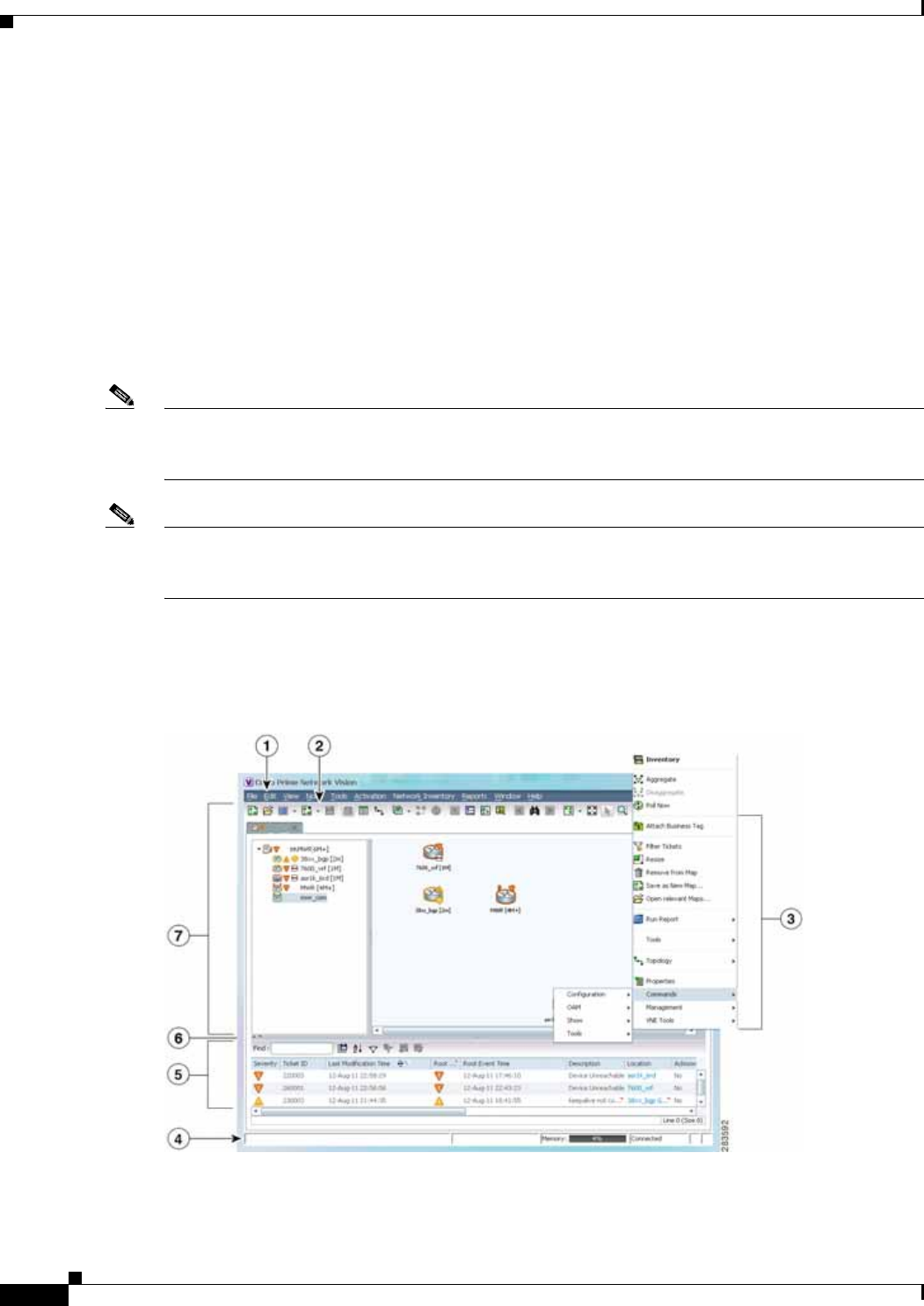
Figure 1-1 illustrates how to launch these commands.
Figure 1-1 Launching NE Management and Configuration Commands

1-5
Cisco Prime Network 4.0 User Guide
OL-29343-01
Chapter 1 Setting Up Devices and Using the GUI Clients Setting Up Devices and Validating Device Information
Note You might be prompted to enter your device access credentials. Once you have entered them, these
credentials will be used for every subsequent execution of a command in the same GUI client session. If
you want to change the credentials, click Edit Credentials. Edit Credentials button will not be available
for SNMP commands or if the command is scheduled for a later time.
These topics describe the available commands:
• Configure Basic Device Settings: Name, DNS, NTP, RADIUS, TACACs, ACLs, page 1-5
• Configure SNMP and SNMP Traps on Device, page 1-7
• Configure Device Ports and Interfaces, page 1-7
• View Device and VRF Routing Tables and Device Interface Briefs, page 1-9
• Ping Destinations and VRFs, and View Trace Route from Device, page 1-9
• Change Device Syslog Logging Level, page 1-9
• View, Copy, and Overwrite Device Configuration Files, page 1-10
• View Users (Telnet Sessions) on Device, page 1-10
Configure Basic Device Settings: Name, DNS, NTP, RADIUS, TACACs, ACLs
Use the following commands to configure system-level settings on the real device. Unless otherwise
noted, all of the following commands are launched by right-clicking the device and choosing
Commands > Configuration > System.
These commands can be executed on all network elements that run on Cisco IOS software, Cisco IOS
XR software, Cisco NX OS, and Cisco IOS XE software. You will not be able to execute these commands
on network elements that have Cisco Catalyst OS software.
Configure the Device Host Name and DNS
1Menu Bar 5Ticket Pane
2Tool bar 6Hide/display Ticket Pane
3Device Right-click Menu 7Navigation Pane
4Status Bar
Command Description
Add Host Name
Remove Host Name
Configures the device host name.
Note Be sure to also apply any host name changes to the device in
Prime Network so that the name is also updated in the Prime
Network model.
DNS > Add DNS Server
DNS > Remove DNS Server
Assigns the device to a Domain Name System (DNS) server to
manage translating the host name to and from the device IP address.

1-6
Cisco Prime Network 4.0 User Guide OL-29343-01
Chapter 1 Setting Up Devices and Using the GUI Clients
Setting Up Devices and Validating Device Information
Configure a Device NTP Server
Configure RADIUS or TACACS Server on Device
Configure IP Access Control Lists (ACLs) on Device
Note These commands are not available on Cisco IOS XR devices.
Caution Only advanced users should change ACLs.
Command Description
NTP > Add NTP Server
NTP > Remove NTP Server
Assigns the device to a Network Time Protocol (NTP) server to
manage clock synchronization.
Command Description
TACACS > Add Tacacs Server
TACACS > Remove Tacacs Server
Assigns the device to a Terminal Access Controller
Access-Control System (TACACS) server to manage
authentication (uses TCP or UDP).
TACACS+ > Add Tacacs+ Server
TACACS+ > Remove Tacacs+ Server
Assigns the device to a TACACS+ server to manage
authentication (uses TCP).
RADIUS > Add Radius Server
RADIUS > Remove Radius Server
Assigns the device to a Remote Authentication Dial In User
Service (RADIUS) server to manage centralized
authentication, authorization, and accounting (uses UDP).
Command Navigation Description
Remove Access
List Logical Inventory >
Access Lists > ACL >
Commands > Configuration >
System
Removes an NE’s IP ACL, which filters
traffic by forwarding or blocking routed
packets depending on the ACL entry
configurations.
Remove Access
List Entry Logical Inventory >
Access Lists > double-click ACL >
ACL entry > Commands >
Configuration > System
Removes the specified ACL entry from the
IP ACL.

1-7
Cisco Prime Network 4.0 User Guide
OL-29343-01
Chapter 1 Setting Up Devices and Using the GUI Clients Setting Up Devices and Validating Device Information
Configure SNMP and SNMP Traps on Device
Use the following commands to configure SNMP settings and SNMP traps on the real device. All of the
following commands are launched by right-clicking the device and choosing Commands >
Configuration > System.
Note These commands can be executed on all network elements that run on Cisco IOS software, Cisco IOS
XR software, Cisco NX OS, and Cisco IOS XE software. You will not be able to execute these commands
on network elements that have Cisco Catalyst OS software.
Configure Device Ports and Interfaces
These commands can be executed on all network elements that run on Cisco IOS software, Cisco IOS
XR software, Cisco NX OS, and Cisco IOS XE
Configure Device Ports
Note To apply description or status changes to an interface and port at the same time, use the interface
commands listed in Configure Device Interfaces, page 1-8.
Command Description
SNMP > Add SNMP Configuration
SNMP > Update SNMP Configuration1
SNMP > Remove SNMP Configuration
1. The “Update SNMP configuration” command is not applicable for Cisco UBR10K and RFGW10 cards.
Configures SNMP on the device, including community
settings, read-write access control, view-based access
control, group settings, and so forth.
Note Be sure to also apply any SNMP configuration
changes to the device in Prime Network so that the
settings are also updated in the Prime Network
model.
SNMP > Add Traps
SNMP > Enable Traps
SNMP > Remove Traps
Configures traps on the device (for example, improper
user authentication, restarts, the closing of a connection,
loss of connection to a neighbor router, and so forth). You
can choose traps from a drop-down list.

1-8
Cisco Prime Network 4.0 User Guide OL-29343-01
Chapter 1 Setting Up Devices and Using the GUI Clients
Setting Up Devices and Validating Device Information
Configure Device Interfaces
Command Navigation Description
Add / Remove /
Update port
description
Physical
Inventory >
navigate to port >
Commands >
Configuration
Configures the descriptive information that is displayed
in GUI clients when the port is selected. Examples are
customer information or business case details.
Note Not supported on the Cisco Carrier Packet
Transport (CPT) System.
Change Port Status Disables (Shutdown) or enables (No Shutdown) the port.
An example is disabling (No Shutdown) a port in
response to a fault so that the port will not generate
further errors.
Note Not supported on the Cisco Carrier Packet
Transport (CPT) System.
Modify Port Physical
Inventory >
Ethernet Slot >
navigate to port >
Commands >
Configuration
(Cisco ASR 5000 series only) Controls a variety of
ASR 5000 port characteristics (bindings, contexts, link
aggregations, and so forth). For more information, see
the appropriate Cisco ASR 5000 documentation.
Assign Port to Vlan
DeAssign Port To
Vlan
Logical Inventory >
Routing Entities >
Routing Entity >
interface >
Commands >
Configuration
Controls a port’s VLAN assignment. Enter a VLAN
between 1-4094. When assigned, the port can
communicate only with or through other devices in that
VLAN. When deassigned, you can move a port to a new
VLAN.
Command Navigation Description
Add Interface
Configuration Physical Inventory >
interface > Commands >
Configuration
Configures descriptive information that is
displayed in GUI clients when the interface (or
port) is selected. Examples are customer
information or business case details.
Enable Interface
Disable Interface
Logical Inventory >
Routing Entities >
Routing Entity >
interface > Commands >
Configuration
Disables or enables an interface (and port). An
example is disabling an interface in response to a
fault so that the interface will not generate further
errors.
Update Interface
Configuration
Remove Interface
Configuration
Changes or removes descriptive information that
is displayed in GUI clients when the interface (or
port) is selected. Examples are customer
information or business case details.
Add Loopback
Interface Logical Inventory >
Routing Entities >
Routing Entity >
Commands >
Configuration
Configures a software-only interface that
emulates an interface. If the virtual interface
receives traffic, it immediately reroutes it back to
the device.

1-9
Cisco Prime Network 4.0 User Guide
OL-29343-01
Chapter 1 Setting Up Devices and Using the GUI Clients Setting Up Devices and Validating Device Information
View Device and VRF Routing Tables and Device Interface Briefs
These commands can be executed on all network elements that run on Cisco IOS software, Cisco IOS
XR software, and Cisco NX OS.
View Interface Briefs and IP Routes
Ping Destinations and VRFs, and View Trace Route from Device
Change Device Syslog Logging Level
These commands can be executed on all network elements that run on Cisco IOS software, Cisco IOS
XR software, Cisco NX OS, and Cisco IOS XE software.
Command Navigation Description
Show > IP Route Logical Inventory > Routing Entities >
Routing Entity > Commands Displays the device routing
table.
Show > VRF IP route Logical Inventory > VRFs > VRF >
Commands Displays the routing table of a
selected VRF.
Show > IP >
Interface Brief NE > Commands Lists all IP interfaces on the
device.
Command Navigation Description
OAM > Trace Route
from Device NE > Commands Performs a traceroute to a destination address,
showing how many hops were required and how
long each hop takes.
OAM > Ping >
Destination From Device Pings a specified IP address to see if the
IP address is accessible.
OAM > Traceroute
VRF1
1. Not applicable for Cisco UBR10K and RFGW10 cards.
Logical Inventory >
VRFs > VRF >
Commands
Performs a traceroute from selected VRF to a
destination address, showing how many hops
were required and how long each hop takes.
OAM > Ping VRF1Pings a specified VRF to see if the VRF is
accessible.
Command Navigation Description
Syslog Host
Logging NE > Commands >
Configuration >
System
Changes the syslog logging level to one of the following:
alerts, critical, debugging, emergencies, errors,
informational, notifications, warnings

1-10
Cisco Prime Network 4.0 User Guide OL-29343-01
Chapter 1 Setting Up Devices and Using the GUI Clients
Using Prime Network with Prime Central
View, Copy, and Overwrite Device Configuration Files
These commands can be executed on all network elements that run on Cisco IOS software, Cisco IOS
XR software, Cisco NX OS, and Cisco IOS XE softwar
View Users (Telnet Sessions) on Device
Using Prime Network with Prime Central
Prime Network can be installed as a standalone product or with Cisco Prime Central. When installed with
Cisco Prime Central, you can launch Prime Network GUI clients from the Cisco Prime Portal.
Cross-launch to and from other suite applications is also supported. The applications share a common
inventory.
The Cisco Prime Portal uses a single sign-on (SSO) mechanism so that users need not reauthenticate with
each GUI client. All session management features are controlled by the portal (such as client timeouts).
If a user tries to log into a standalone GUI client, the user will be redirected to the portal login. The only
exception is the emergency user, who will still be allowed to log into a standalone GUI client.
If the Cisco Prime Performance Manager application is also installed, the Prime Network Event
Collector will receive threshold crossing alarm (TCA) events from Prime Performance Manager
components and generate a ticket that you can view in Prime Network Events.
Command Navigation Description
Write memory NE > Commands >
Configuration Overwrites the startup-config file with the current
running-config.
Note Not supported on Cisco IOS XR devices.
Show > Running
Config NE > Commands Displays the contents of the device’s current
running-config (which can be different from the
running-config on file).
Show > Startup
Config Displays the contents of the device’s current
startup-config.
From FTP
From TFTP
NE > Commands >
Tools > File copy
Note Not supported
on Cisco
Carrier Packet
Transport
(CPT) System.
Copies the starting-config or running-config file from a
remote source to a local location. The remote source is
identified by its IP address. FTP requires the FTP
username and password.
To FTP
To TFTP
Copies a local configuration file to a remote destination’s
starting-config or running-config file. The remote
destination is identified by an IP address. FTP requires
the FTP username and password.
Command Navigation Description
Users (Telnet Sessions) NE > Commands > Show Provides details about the device’s current
Telnet sessions.

1-11
Cisco Prime Network 4.0 User Guide
OL-29343-01
Chapter 1 Setting Up Devices and Using the GUI Clients Using Prime Network with Prime Central
Prime Network also receives EPM-MIB traps from the network. By default Prime Network receives
EPM-MIB traps from any source in the network. If desired, you can configure Prime Network to only
process EPM-MIB traps arriving from a specific Prime Performance Manager server. The instructions
for doing this are provided on the Cisco Developer Network at
http://developer.cisco.com/web/prime-network/home.

1-12
Cisco Prime Network 4.0 User Guide OL-29343-01
Chapter 1 Setting Up Devices and Using the GUI Clients
Using Prime Network with Prime Central

CHAPTER
2-1
Cisco Prime Network 4.0 User Guide
OL-29343-01
2
Working with the Prime Network Vision Client
The following topics describe the user access roles required to use Cisco Prime Network Vision (Prime
Network Vision), the Prime Network Vision working environment, and how to access the Prime Network
Vision tools and commands:
• User Roles Required to Work with Basic Operations in Prime Network Vision, page 2-1
• Launching Prime Network Vision, page 2-2
• Changing Your GUI Client Password, page 2-4
• The Prime Network Vision Window, page 2-4
• Prime Network Vision Status Indicators, page 2-17
• Prime Network Vision Toolbar, page 2-23
• Prime Network Vision Menu Bar, page 2-25
• Prime Network Vision Right-Click Menus, page 2-31
• Adjusting the Prime Network Vision GUI Client Settings, page 2-40
• Filtering and Sorting Tabular Content, page 2-42
User Roles Required to Work with Basic Operations in Prime
Network Vision
Table 2-1 identifies the GUI default permission or device scope security level that is required to work
with Prime Network Vision. Prime Network Vision determines whether you are authorized to perform a
task as follows:
• For GUI-based tasks (tasks that do not affect devices), authorization is based on the default
permission that is assigned to your user account.
• For element-based tasks (tasks that do affect elements), authorization is based on the default
permission that is assigned to your account. That is, whether the element is in one of your assigned
scopes and whether you meet the minimum security level for that scope.
For more information on user authorization, see the Cisco Prime Network 4.0 Administrator Guide.
By default, users with the Administrator role have access to all managed elements. To change the
Administrator user scope, see the topic on device scopes in the Cisco Prime Network 4.0 Administrator
Guide.

2-2
Cisco Prime Network 4.0 User Guide OL-29343-01
Chapter 2 Working with the Prime Network Vision Client
Launching Prime Network Vision
Launching Prime Network Vision
Prime Network Vision is password protected to ensure security. Before you start working with Prime
Network Vision, make sure you know your username and password. If you use the standalone
application, you also need to know the Prime Network Vision gateway IP address or hostname.
• Launch Prime Network Vision from Prime Central—Choose Assure > Prime Network > Vision in
the menu bar. The Prime Network Vision application is opened in a separate window. For
information on Prime Central, see the Cisco Prime Central User Guide.
• Launch Prime Network Vision as a Standalone Application—Choose
Start > Programs > Cisco Prime Network > gateway IP address > Cisco Prime Network Vision,
and enter your username and password. If any client updates are available, Prime Network
automatically installs them.
If you see messages that say the server and client have different versions of the application, you need
to update your client as described in the Cisco Prime Network 4.0 Installation Guide.
The Prime Network Vision GUI opens with the Network Elements tab as default as shown in Figure 2-1.
Table 2-1 Default Permission/Security Level Required for the Basic Prime Network Vision
Functions
Task Viewer Operator OperatorPlus Configurator Administrator
Start Prime Network
Vision XXXXX
Change a user password
in Prime Network
Vision
—1—1—1—1X1
1. Each user can change their own password, but only the Administrator role can change another user’s password.
Set Prime Network
Vision options XXXXX
Work with Prime
Network Vision tables XXXXX

2-3
Cisco Prime Network 4.0 User Guide
OL-29343-01
Chapter 2 Working with the Prime Network Vision Client Launching Prime Network Vision
Figure 2-1 Prime Network Vision with Network Elements Tab
This tab contains the following radio buttons:
• Search—This radio button is selected by default and allows you to search for a device by selecting
any one of the following options and specifying the relevant search criteria:
–
Element Type
–
IP Address
–
Name
–
Product
–
System Name
–
Vendor
• Show All—Selecting this option will display all the devices available in your network.
Once the GUI client is displayed, open an existing map or create a new one; see Working with Prime
Network Vision Maps, page 5-1.
Note If this is not the first time you are logging into Prime Network Vision GUI, then the Prime Network
Vision GUI opens with the default Network Elements tab along with the Last Open Maps dialog box.
This dialog box will list the names of the maps that you opened previously along with a selected check
box next to it. If you want to open the same maps again, then click the OK button. Otherwise, close the
dialog box.

2-4
Cisco Prime Network 4.0 User Guide OL-29343-01
Chapter 2 Working with the Prime Network Vision Client
Changing Your GUI Client Password
After logging into Prime Network Vision and launching the application, you can customize the Prime
Network Vision settings. For example, you can:
• Load the content pane with information when starting Prime Network Vision.
• Display network elements in the Prime Network Vision content pane and navigation pane.
• Configure audio responses when different alarms are triggered.
• Specify the length of time that events should be displayed in the inventory window.
For more information on customizing Prime Network Vision startup and display options, see Adjusting
the Prime Network Vision GUI Client Settings, page 2-40.
Changing Your GUI Client Password
The method used to change your password depends on whether authentication is provided by Prime
Network or an LDAP server. If you can see the Tools > Change User Password choice in the Prime
Network Vision menu, the system is using authentication provided by Prime Network. You can change
your password by entering the old and new passwords.
If the menu choice is disabled, the system is using an external authentication method. To change your
password, contact your administrator. For more information about user authentication, see the
Cisco Prime Network 4.0 Administrator Guide.
The Prime Network Vision Window
Figure 2-2 displays the Prime Network Vision window with an open map.
Tip The ticket pane can be displayed or hidden by clicking the arrows below the navigation pane (see Callout
7 in Figure 2-2).
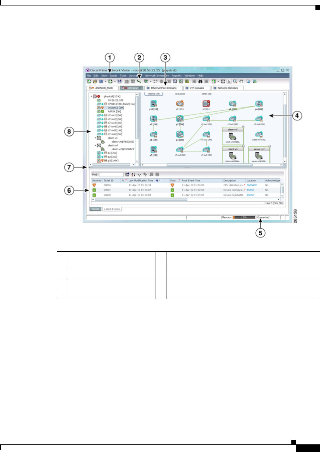
2-5
Cisco Prime Network 4.0 User Guide
OL-29343-01
Chapter 2 Working with the Prime Network Vision Client The Prime Network Vision Window
Figure 2-2 Prime Network Vision Window
Prime Network Vision Inventory Tabs
Prime Network Vision includes the following inventory tabs:
• Network Elements—Lists all network elements with the information described in Table 2-7,
Network Element Information Displayed in List View. If there are tickets associated with the
element, an icon is displayed. The color of the icon indicates the ticket severity.
• Ethernet Flow Domains—Lists all Ethernet flow domains, including the domain name, the
system-defined domain name, and a brief description for each domain. For more information about
Ethernet flow domains, see Viewing and Renaming Ethernet Flow Domains, page 12-42.
• VTP Domains—Lists all VTP domains. For more information about VTP domains, see Viewing
VLAN Trunk Group Properties, page 12-68.
1GUI client menu bar 5GUI client status bar (amount of memory used by client
and gateway connection status)
2GUI client toolbar 6List of tickets on selected item
3Active map and inventory tabs 7Toggle to hide/display ticket pane
4Map view (content pane) 8Inventory window (navigation pane)
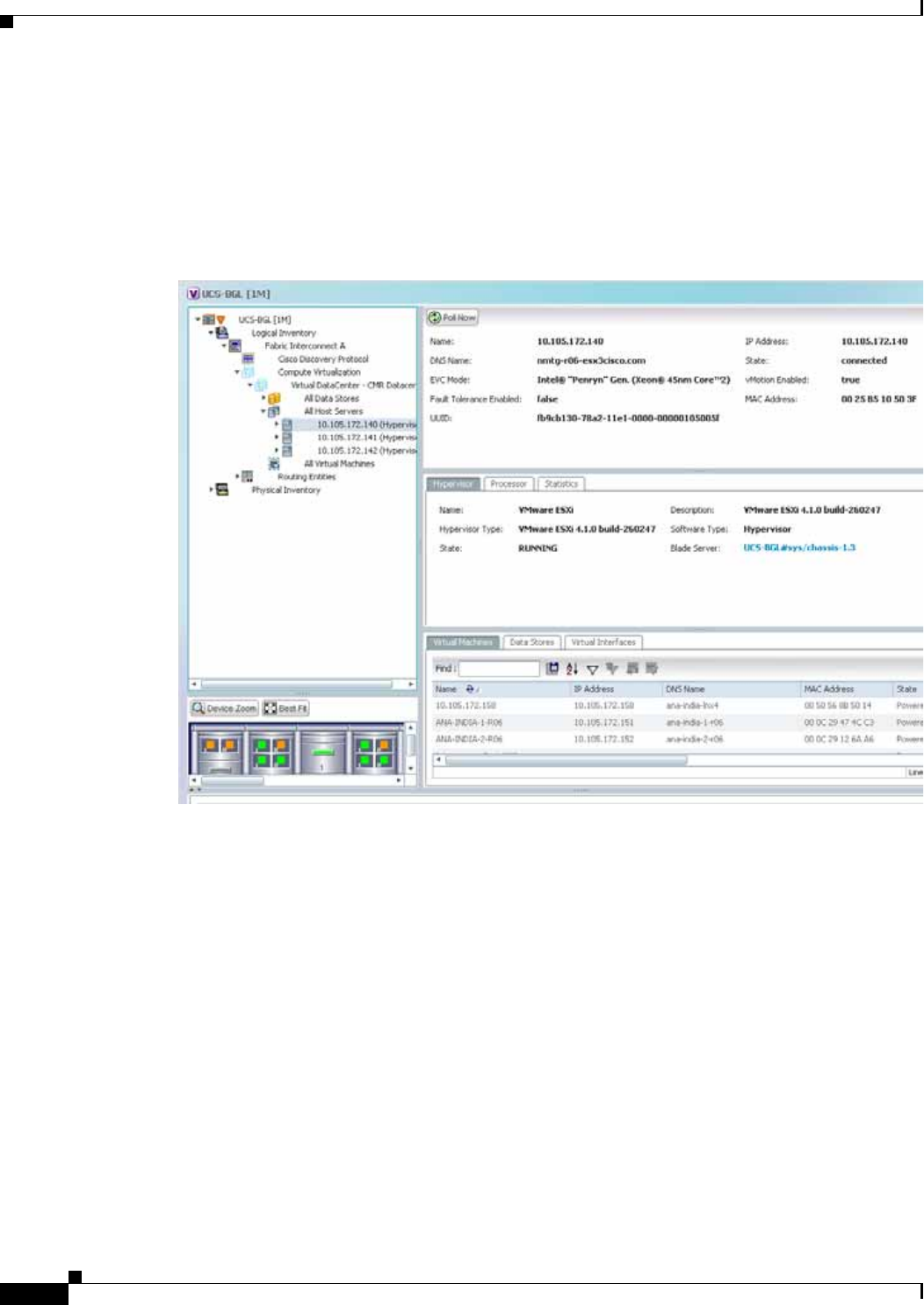
2-6
Cisco Prime Network 4.0 User Guide OL-29343-01
Chapter 2 Working with the Prime Network Vision Client
The Prime Network Vision Window
• Virtual Machines—Lists all the virtual machines. For more information about virtual machines, see
Viewing the Virtual Machines of a Data Center, page 26-19. If there are tickets associated with the
virtual machine, an icon is displayed. The color of the icon indicates the ticket severity.
To open an inventory tab, choose Network Inventory in the menu bar, and choose the required option.
The selected inventory table is displayed as shown in Figure 2-3.
Figure 2-3 Prime Network Vision Inventory Tabs
Prime Network Vision Maps
You can create as many maps as required to represent the network views you need. For example, maps
can include specific network segments, customer networks, or the particular network elements and
services that you require. Each map has three major areas:
• A tee-and-branch representation of the network elements and aggregations in the current map. For
more information, see Navigation Pane, page 2-7.
• A large area showing the map elements and links in a map (topological layout) or in list format. For
more information, see Content Pane: Map, List, and Links Views, page 2-8.
• A table of tickets associated with elements displayed in the map. For more information, see Ticket
Pane, page 2-17.
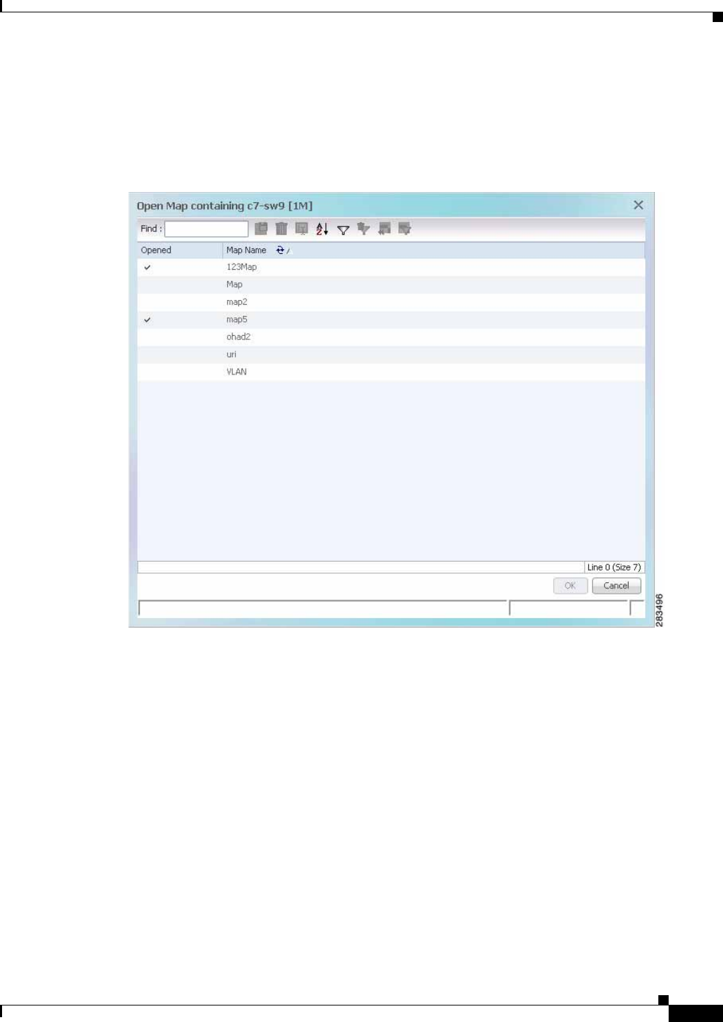
2-7
Cisco Prime Network 4.0 User Guide
OL-29343-01
Chapter 2 Working with the Prime Network Vision Client The Prime Network Vision Window
Opening Maps
You can open up to five maps at one time. To open a map, choose File > Open Map. The Open Map
dialog box is displayed (see Figure 2-4).
Figure 2-4 Open Map Dialog Box
A check mark in the Opened column indicates that the map is already open. Map tabs display the root
node icon and name.
In addition, the icon color reflects the highest severity ticket that is not cleared in the map, and an alarm
icon indicates the severity of the highest severity ticket that is not acknowledged. For more information
about maps, see Working with Prime Network Vision Maps, page 5-1.
You can open up to eight tabs at one time.
Navigation Pane
The navigation pane displays a tree-and-branch representation of the network elements and aggregations
defined for the loaded map.
The highest level in the navigation tree displays root node icon with the map name. When the map name
is changed, the Prime Network Vision window is updated, and the new map name is displayed at the top
of the navigation tree and in the window title bar.
The lowest level of the navigation tree displays a single network element or service, such as a port,
Ethernet flow point, or bridge.

2-8
Cisco Prime Network 4.0 User Guide OL-29343-01
Chapter 2 Working with the Prime Network Vision Client
The Prime Network Vision Window
The navigation pane can include up to two icons for each element. These icons can include alarm icons,
communication or investigation state icons, and badges, as shown in Figure 2-5. Alarm icons are always
displayed next to the element icon.
Figure 2-5 Navigation Pane with Icons
For information about the status of network objects, see Prime Network Vision Status Indicators,
page 2-17.
Content Pane: Map, List, and Links Views
The content pane enables you to view and modify low-level information. It supports the following views:
• Map view—Displays managed network elements on a geographical map. For more information, see
Map View, page 2-8.
• List view—Displays the details of the network elements contained in the currently selected
hierarchy or subnetwork (map), such as the IP address and system name. For more information, see
List View, page 2-12.
• Links view—Displays a complete list of the links in the map view and their status. For more
information, see Links View, page 2-15.
Map View
Click Show Map View on the toolbar to display the map view in the Prime Network Vision window. In
the map view, Prime Network Vision displays:
• Aggregations
• Managed network elements
–
Each network element is displayed as an icon, the color of which reflects severity, as described
in Alarm Indicators, page 2-12.
–
Depending on the size of the icon, additional information can be displayed. For more
information, see Information Available in Element Icons, page 3-3.
• Ethernet flow point cross-connects
• Ethernet services
• MPLS-TP tunnels
• Pseudowires
• VLANs
• VPLS instances
• VPNs

2-9
Cisco Prime Network 4.0 User Guide
OL-29343-01
Chapter 2 Working with the Prime Network Vision Client The Prime Network Vision Window
• Links
–
Service and business links are represented as well as physical and topological links.
–
Unidirectional links include arrowheads that indicate the direction of the flow, while
bidirectional links do not have arrowheads.
• Relationships between network elements, aggregations, and networks
You can move network elements manually on the map by dragging the required icon. You can also click
Layout Map in the toolbar or use your mouse to change the way the elements are displayed on the map.
For more information about working with maps, see Chapter 5, “Working with Prime Network Vision
Maps.”
Element Icons
To view icons more easily, zoom in with your mouse. Four sizes are supported. Table 2-2 provides
examples of each. For more details about data this is displayed, see Information Available in Element
Icons, page 3-3.
Prime Network Vision also provides additional features for working with aggregations. For more
information, see Working with Aggregations, page 5-16.
The following tables identify some of the icons used to represent network elements and business
elements in the Prime Network Vision window’s navigation pane and content pane:
• Table 2-3, Network Element Icons
• Table 2-4, Business Element Icons
Table 2-2 Prime Network Vision Element Icon Sizes
Example Icon Name and Description
Tiny—Elements are displayed as dots. Alarm severity is indicated by colors.
Normal—Elements are displayed with icons and names. Alarms include
badges. Alarm severity is represented by colors.
Large—Same as Normal, with additional NE properties. You can also
perform cut-and-paste operations by pressing and dragging the mouse scroll
wheel over the text.
Huge—Same as Normal, with additional action buttons.
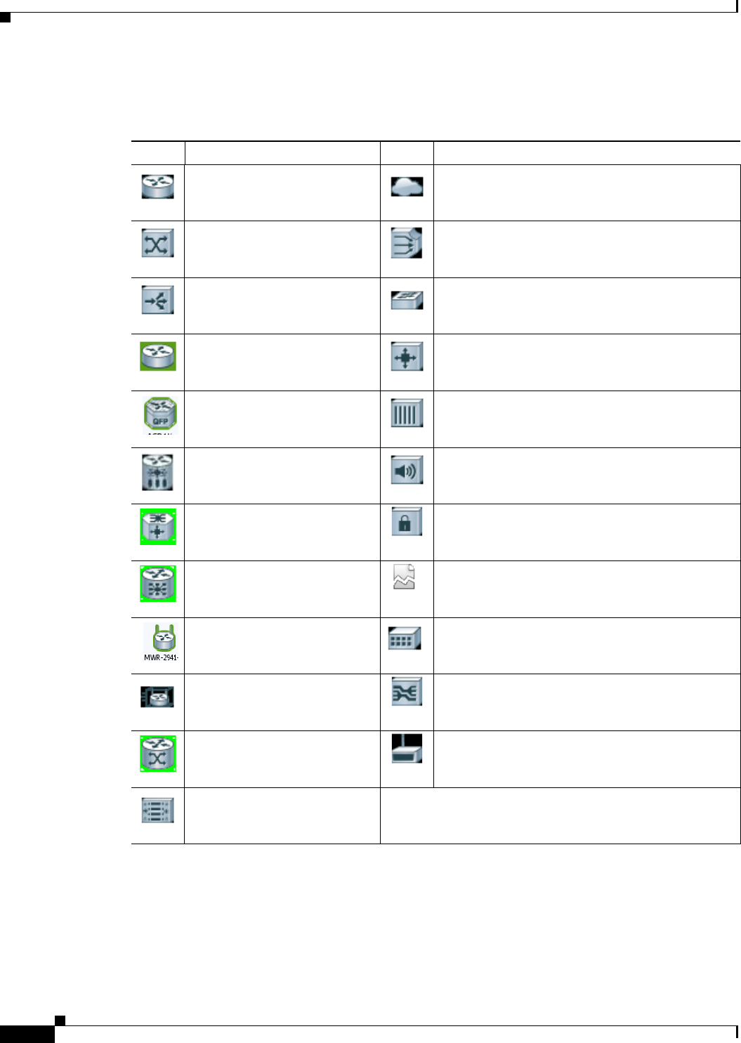
2-10
Cisco Prime Network 4.0 User Guide OL-29343-01
Chapter 2 Working with the Prime Network Vision Client
The Prime Network Vision Window
For a complete list of the icons and their descriptions, see Appendix A, “Icon and Button Reference.”
Table 2-3 Network Element Icons
Icon Network Element Icon Network Element
Access pseudowire
Router
Cloud
ATM switch Digital subscriber line access multiplexer
(DSLAM)
Basic rate access (BRA) Ethernet switch
Cisco 7600 series router Generic SNMP device
Cisco ASR 1000 series router Ghost, or unknown device
Cisco ASR 5000 series router ICMP device
Cisco ASR 9000 series router Lock, or security violation; viewable by a user with
a higher permission level
Cisco CRS series router Missing icon or ghost NE (the NE was deleted and
is no longer managed, or there is no icon for this
NE)
Cisco MWR 3941 Sun Netra server
Cisco Nexus 1000 series
devices Service control switch
Cisco IOS XR 12000 series
router WiFi element
Cisco Unified Computing
System (UCS)
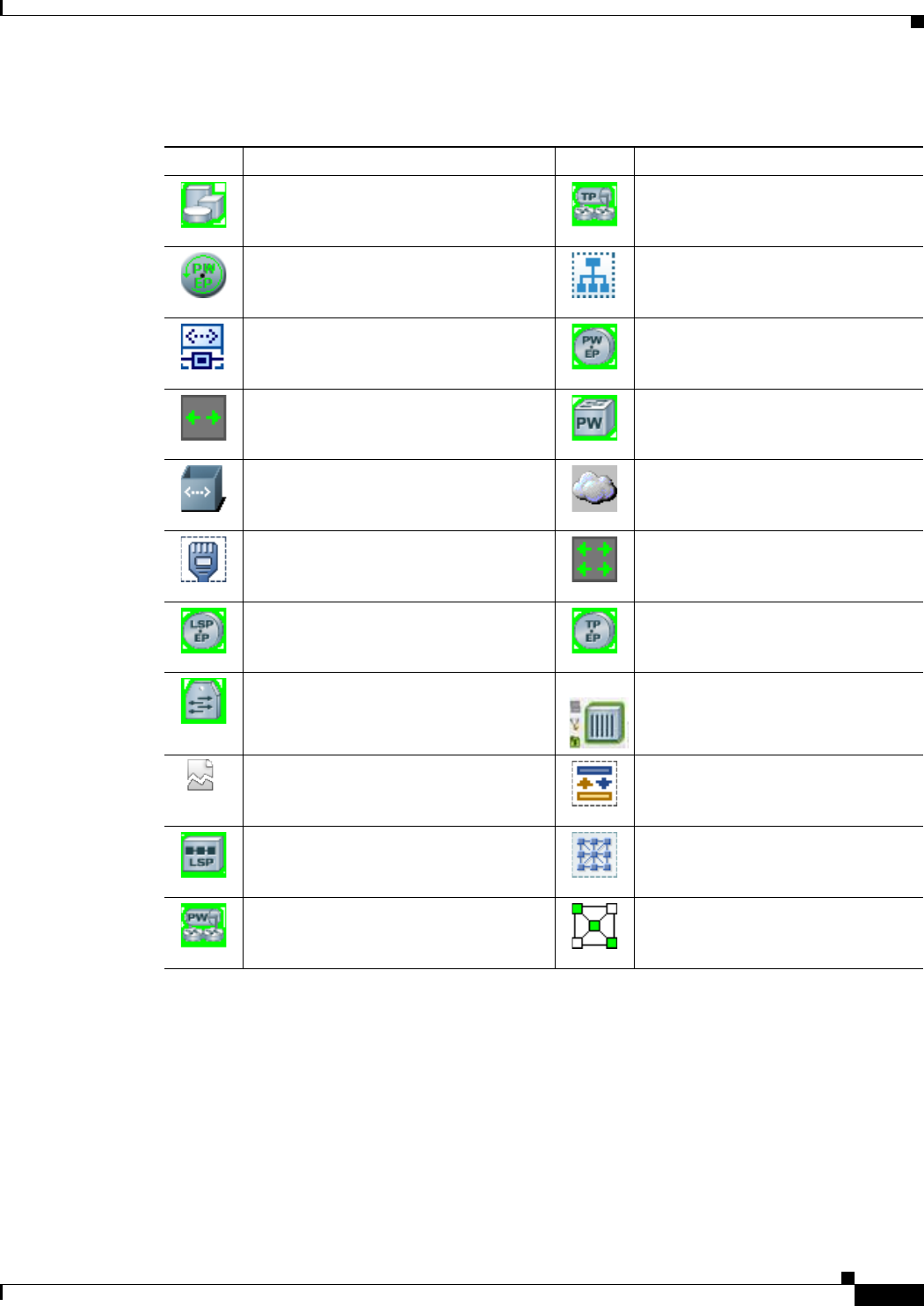
2-11
Cisco Prime Network 4.0 User Guide
OL-29343-01
Chapter 2 Working with the Prime Network Vision Client The Prime Network Vision Window
Links
Prime Network Vision maps contain graphical links that can represent multiple physical, topological,
service, and business links. The maximum number of graphical links that can be displayed is specified
in the registry. If the number of graphical links exceeds the specified limit, a warning message with a
Refresh button is displayed, and the map is surrounded by a red border. The presence of a red border
around a map indicates that some links exist that are not displayed in the map.
Table 2-4 Business Element Icons
Icon Business Element Icon Business Element
Aggregation or root node Network Traffic Profile (TP) tunnel
Backup pseudowire edge Network VLAN
Connection termination point (TP)
Ethernet flow point (EFP)
MToP service
Pseudowire edge
EFP cross-connect Pseudowire switching entity
Ethernet service Subnet
Ethernet virtual connection (EVC) Switching entity
Label-Switched Path (LSP) endpoint TP tunnel endpoint
LSP midpoint vCenter VNE
Missing icon or ghost NE (the NE was
deleted and is no longer managed, or
there is no icon for this NE)
VPLS forward
Network LSP
Protected LSP
Working LSP
VPLS instance
Network pseudowire VPN

2-12
Cisco Prime Network 4.0 User Guide OL-29343-01
Chapter 2 Working with the Prime Network Vision Client
The Prime Network Vision Window
To reduce the number of graphical links in a map, click Link Filter in the toolbar, and uncheck the check
boxes for the links you do not need to view.
Links in maps have tooltips that provide you with information regarding the link endpoints and the
number of links represented by the selected link in the map. Click the link tooltip to view additional
information about the link in a link quick view window. Click Properties in the link quick view window
to open the link properties window. For more information about viewing link properties, see Viewing
Link Properties in Prime Network Vision Maps, page 6-4.
Note If you apply a link filter to the map, the link tooltip displays only the relevant links.
Alarm Indicators
Table 2-5 shows the colors that are used to display the severity (or propagated severity) of a network
element. The same coloring conventions apply to the link severities.
Note The color of a selected link can be customized. The default color is blue.
Right-Click Functions
Many functions can be performed by using the right-click menu in the map view, including launching
external applications or tools. Some of these functions are also available in the navigation pane, links
view, and ticket pane.
The specific options that are available in the right-click menu depend on whether you select a network
element, click in the map background, select an aggregation, or select a ticket in the ticket pane. For
details on the specific right-click options that are available for each scenario, see Prime Network Vision
Right-Click Menus, page 2-31.
List View
Click Show List View in the toolbar to display the Prime Network Vision list view. The list view displays
the tabs described in Table 2-6, depending on the items included in the current map and the item selected
in the navigation tree.
Table 2-5 Severity Indicators
Icon Color Severity Icon Color Severity
Red Critical Light Blue Warning
Orange Major Medium Blue Information
Yellow Minor Dark blue Indeterminate
Green Cleared, Normal, or
OK

2-13
Cisco Prime Network 4.0 User Guide
OL-29343-01
Chapter 2 Working with the Prime Network Vision Client The Prime Network Vision Window
Table 2-7 describes the network element properties displayed in the Network Elements tab. (Locked
network elements display only managed element information and the locked element icon.) To ensure
that you are viewing the latest information, either perform a new search or click the Refresh button.
Table 2-6 Prime Network Vision List View Tabs
Tab Description
Aggregations Aggregations in the current map.
Connection TP Connection termination points (TPs) in the current map.
EFP Cross-Connect EFP cross-connects in the current map.
Ethernet Flow Points EFPs in the current map.
Ethernet Services Ethernet services in the current map.
EVCs EVCs in the current map.
Network Elements Network elements in the current map that are in the user’s scope.
Network Pseudowire Network pseudowires in the current map.
Network TP Tunnel Network Traffic Profile (TP) tunnels in the current map.
Pseudowires Pseudowires in the current map.
Pseudowire Edge Pseudowire endpoints in the current map.
PW Switching Entity Pseudowire switching entities in the current map.
Restricted Elements Network elements in the current map that are not in the user’s scope.
Sites Sites for the selected VLAN. Site properties include site name, description,
location, and IP interface.
Switching Entities Switching entities in the current map.
Virtual Routers Virtual routers on the selected VLAN. Virtual router properties include the
virtual router name and description.
VLANs VLANs in the current map. VLAN properties include VLAN name,
identifier, description, and Ethernet flow points.
VPLS Forward VPLS forwards in the current map.
VPLS Instance VPLS instances in the current map.
VPNs VPNs in the current map. VPN properties include VPN name and description
Table 2-7 Network Element Information Displayed in List View
Field Name Description
Name Name of the network element managed by Cisco, as defined in Cisco Prime
Network Administration. The Name property also displays a network
element icon. The icon color reflects the highest network element alarm
severity. In addition, the management state or an alarm icon is displayed.
IP Address IP address used for managing the network element.
System Name System name of the network element, as defined in the network element's
MIB. If the network element is configured for Telnet access, the prompt is
displayed.
Severity Current operational health of the network element.

2-14
Cisco Prime Network 4.0 User Guide OL-29343-01
Chapter 2 Working with the Prime Network Vision Client
The Prime Network Vision Window
Tip Click the red triangle in a cell to expand the cell and view all the information it contains. You can also
use a tooltip to view all the information.
See Filtering and Sorting Tabular Content, page 2-42 for more information about filtering, finding
details about a network element in Prime Network Vision tables.
Table 2-8 describes some of the functions that are available from the right-click menu in the list view.
You must select an item for the right-click menu to appear. Not all options are available for all selections.
Unacknowledged Severity of the most severe unacknowledged ticket.
Communication State Ability of the VNE to reach the network element, according to the health of
the element. For more information about communication states, see the
Cisco Prime Network 4.0 Administrator Guide.
Investigation State Level of network element discovery that has been performed or is being
performed by the VNE. For more information about investigation states, see
the Cisco Prime Network 4.0 Administrator Guide.
Vendor Vendor name.
Product Network element category, such as Router or Eth-Switch (Ethernet switch).
Device Series Device series, such as Cisco 7600 Series Routers.
Element Type Network element type including the manufacturer’s name, such as
Cisco 7200.
Software Version Cisco IOS software version running on the network element.
Location Location of the network element.
Up Since Date and time the network element was last reset.
Table 2-7 Network Element Information Displayed in List View (continued)
Field Name Description
Table 2-8 List View Right-Click Options
Right-Click Option Function Related Documentation
Inventory View network element inventory Inventory Window, page 3-9
Poll Now Poll the selected element
Attach / Detach / Edit
Business Tag Configure and view business tag information Chapter 7, “Labeling NEs Using
Business Tags”
Config Mgmnt View the Configuration Management page in
Prime Network Change and Configuration
Management
Chapter 4, “Device Configurations and
Software Images”
Image Mgmnt View the Image Management page in Prime
Network Change and Configuration Management Chapter 4, “Device Configurations and
Software Images”
Run Report Generate reports Chapter 10, “Working with Reports”
Tools Ping or telnet a VNE, or check VNE CPU usage List View Right-Click Menu, page 2-37
Topology Configure the topology Adding Static Links, page 6-15

2-15
Cisco Prime Network 4.0 User Guide
OL-29343-01
Chapter 2 Working with the Prime Network Vision Client The Prime Network Vision Window
Tip Click a column heading in a table to sort the information by that property.
Links View
Click Show Links View in the toolbar to display the links view in the Prime Network Vision window.
Maps can contain many graphical links, each of which can represent multiple physical, topological,
service, and business links. This can make it difficult for you to view the links you are interested in. In
addition, if the number of graphical links exceeds the number that can be displayed in a map, not all links
are displayed. By using the links view, you can view all links in the map, as well as search for a specific
link and view the status of a link.
Note You can view and filter the links according to type by using the Link Filter dialog box. For more
information, see Filtering Links in a Map, page 5-25.
Any links that are added or removed from the map are automatically added or removed from the links
view, provided they have not been filtered out.
The links view is selection sensitive; that is, the links displayed in the links view depend on the context
selected in the navigation pane or map. For example, if an aggregation is selected, the links in the
selected aggregation are displayed in the links view.
Properties View network element properties Viewing the Properties of a Network
Element, page 3-6
Commands Launch any of the commands that are included
with Prime Network Vision Setting Up Devices and Validating
Device Information, page 1-4
Management Access Command Builder and Soft Properties
Management
Cisco Prime Network 4.0 Customization
Guide
VNE Tools Poll a VNE, or start or stop a VNE Performing a Manual Device Poll,
page 3-18
Table 2-8 List View Right-Click Options (continued)
Right-Click Option Function Related Documentation
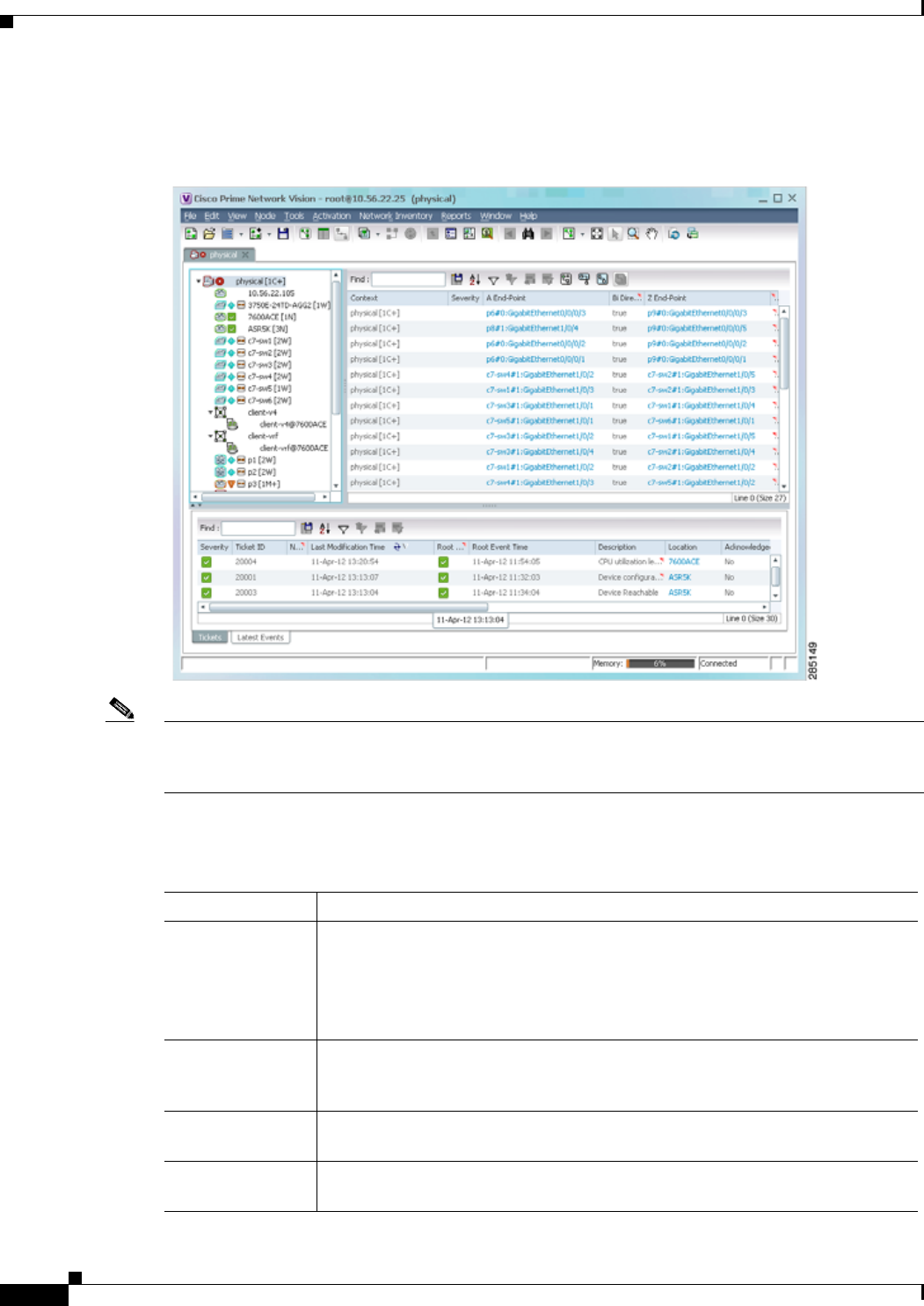
2-16
Cisco Prime Network 4.0 User Guide OL-29343-01
Chapter 2 Working with the Prime Network Vision Client
The Prime Network Vision Window
Figure 2-6 shows a links view.
Figure 2-6 Links View
Note An external link has a blue cell background in the table, and you can open the inventory window by
clicking the hyperlink. For more information about external links, see Viewing Link Properties in the
Links View, page 6-8.
Table 2-9 describes the information that is displayed in the links view.
Table 2-9 Information Displayed in the Links View
Field Name Description
Context Name of the map or aggregation containing the link.
This field can be empty for either of the following reasons:
• One side of the link is not included in the map.
• The link is filtered out of all contexts.
Severity Link alarm severity, represented by an icon. The icon and its color indicate the
alarm severity and thereby the impact of the alarm on the network. For more
information about severity, see Map View, page 2-8.
A End-Point Element or site that is the source of the link as a hyperlink to the inventory of the
element or site.
Bi Directional Whether the link is bidirectional or unidirectional: true (bidirectional) or false
(unidirectional). If the link is unidirectional (false), the traffic is from A to Z.

2-17
Cisco Prime Network 4.0 User Guide
OL-29343-01
Chapter 2 Working with the Prime Network Vision Client Prime Network Vision Status Indicators
The links view toolbar includes the tools described in Table 2-10 and the link filtering buttons described
in Table 2-10.
For more information about filtering and sorting links in the links view, see Viewing Link Properties in
the Links View, page 6-8.
For information about the right-click options available in the links view, see Links View Right-Click
Menu, page 2-39.
Ticket Pane
The ticket pane shows the tickets that relate to the elements in the displayed map. It also contains the
Latest Events tab that shows the latest incoming events for the elements in the map from the time the
map was opened. See Chapter 9, “Working with Tickets in Prime Network Vision” for more information.
Prime Network Vision Status Indicators
The following topics describe the ways in which the status of an element is displayed in Prime Network
Vision:
• Severity, page 2-18
• VNE Management States, page 2-19
• Tickets, page 2-23
Z End-Point Element or site that is the destination of the link as a hyperlink to the inventory
of the element or site.
Link Type Type of link, such as Physical Layer, LAG, MPLS TE Tunnel, pseudowire (PW)
or VPN.
Table 2-9 Information Displayed in the Links View (continued)
Field Name Description
Table 2-10 Link Filtering Buttons
Button Name Description
All Links Displays the complete list of links for the selected context (map or
aggregation). In other words, the list is not filtered and all the links are
displayed, including external links.
External Links Displays links with only one side of the link in this context (map or
aggregation) and the other side either not in the map or outside the selected
context.
Flat Links Displays the links currently visible on the map for the selected context
(map or aggregation), excluding any thumbnails.
Deep Links Displays the links for the current aggregation where both endpoints are
within the currently selected context.
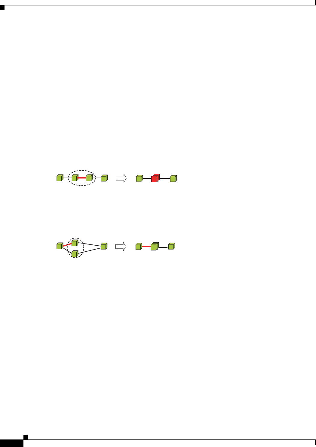
2-18
Cisco Prime Network 4.0 User Guide OL-29343-01
Chapter 2 Working with the Prime Network Vision Client
Prime Network Vision Status Indicators
Severity
Severity indicates the operational health of the element. An element has only one severity value at any
given time, and this value is displayed using a severity color. For more information about the colors used
to display the severity (or propagated severity) of network elements and links, see Alarm Indicators,
page 2-12.
Propagation
Severity is propagated upward in the network hierarchy, displaying the top-most severity of the network
element’s children and thereby ensuring that every single problem in the network is propagated and
visible.
The same severity propagation rules that are used for network elements apply to links. A link is a child
object of an aggregation only if it is fully contained in the aggregation; that is, the network elements on
both sides of the link are part of the aggregation, as shown in Figure 2-7 and Figure 2-8.
Figure 2-7 Link Severity Example 1
Figure 2-7 shows critical link 1 between two network elements in an aggregation. This critical link
affects the severity of aggregation 2. That is, the aggregation is critical because it contains a link with a
critical severity. Link severity affects the context.
Figure 2-8 Link Severity Example 2
Figure 2-8 shows critical link 1 that forms part of a link aggregation. This affects the severity of link 2
because it contains a link with a critical severity.
New Ticket Propagation
A new ticket indicates a new local fault or accumulates and propagates the number of new faults in its
children.
12
180111
12
180112

2-19
Cisco Prime Network 4.0 User Guide
OL-29343-01
Chapter 2 Working with the Prime Network Vision Client Prime Network Vision Status Indicators
When new tickets are accumulated, a label is displayed in the navigation pane and map, based on the
following formula:
n s [+]
where:
For example:
• An object with three critical new alarms, two major alarms, and one warning alarm is labeled 3C+.
• An object with five minor new alarms is labeled 5m.
An icon represents unacknowledged tickets, and the icon color is that of the most severe,
unacknowledged ticket. For more information about severity colors and icons, see Alarm Indicators,
page 2-12.
If all relevant tickets are acknowledged, no bell is displayed.
VNE Management States
VNEs are the building blocks of the Prime Network model because each VNE maintains a real-time
model of a single device, and together, VNEs maintain a model of the entire network. VNE management
states indicate:
• Whether a VNE can communicate with the device it is modeling and with other Prime Network
components (communication state)
• How successfully a VNE has modeled the device it represents (investigation state)
This enables you to determine the accuracy of the network information and the availability of VNEs to
carry out network operations.
Management states are always local indications and are not propagated. A partial exception to this rule
is the propagation of unreachable VNEs. The management state indication applies only to VNE and its
components. A VNE can have only one state at a time (for example, Unsupported or Connecting).
Symbol Description
nThe number of alarms with the highest severity that have the source as the
network element and are part of the network element ticket(s).
sThe highest severity level in the new tickets:
• C = Critical
• M = Major
• m = Minor
• W = Warning
• N = Normal (cleared alarm)
• i = Informational
+Additional, less severe tickets (optional) exist.

2-20
Cisco Prime Network 4.0 User Guide OL-29343-01
Chapter 2 Working with the Prime Network Vision Client
Prime Network Vision Status Indicators
A managed VNE icon consists of a managed element icon and one or two overlay icons, or badges:
• The managed element icon displays a symbol of the element, and the color of the symbol indicates
the highest severity ticket that is not cleared for the element.
An element icon is colored green if either of the following is true:
–
No ticket of any severity exists for the element.
–
All tickets that exist for the element have the severity Cleared or Informational.
For more information about network element icons, see Element Icons, page 2-9. For more
information about severity colors, see Alarm Indicators, page 2-12.
• An alarm badge is displayed on top of a managed element icon, and the color of the alarm badge
indicates the severity of the highest severity ticket that is not acknowledged for the element. If all
tickets are acknowledged, no alarm icon appears.
Figure 2-9 shows an example of an element with the following ticket and alarm severities:
–
The highest severity ticket that is not cleared for the element is Major, as indicated by the orange
color applied to the element icon.
–
The highest severity alarm that is not acknowledged for the element is Cleared or OK, as
indicated by the green alarm badge.
Figure 2-9 Element with Ticket and Alarm Severity Indicators
• A VNE management state badge is displayed on top of the managed element icon to indicate the
management state of the VNE in the navigation tree and map. For example, a router that is partially
reachable by Prime Network Vision is displayed as illustrated in Figure 2-10.
Figure 2-10 Element with Overlay Badges
1Element icon with severity Major (orange)
2Alarm badge with severity Cleared or OK (green)
1Alarm badge with severity Warning.
2Managed element icon with severity Warning.
3VNE management state badge of Device Partially Reachable.
1
2
3
310517

2-21
Cisco Prime Network 4.0 User Guide
OL-29343-01
Chapter 2 Working with the Prime Network Vision Client Prime Network Vision Status Indicators
Table 2-11 and Table 2-12 describe network element communication and investigation states and shows
the related badge for each state.
Table 2-11 VNE Communication States
State Name Description Badge
Agent Not Loaded The VNE is not responding to the gateway because it was stopped, or it was just
created. This communication state is the equivalent of the Defined Not Started
investigation state.
None
VNE/Agent Unreachable The VNE is not responding to the gateway. This can happen if the unit or AVM is
overutilized, the connection between the gateway and unit or AVM was lost, or the
VNE is not responding in a timely fashion. (A VNE in this state does not mean the
device is down; it might still be processing network traffic.)
Connecting The VNE is starting and the initial connection has not yet been made to the device.
This is a momentary state. Because the investigation state decorator (the hourglass)
will already be displayed, a special GUI decorator is not required.
None
Device Partially Reachable The VNE is not fully reachable because at least one protocol is not operational.
Note This is the default behavior. You can change the settings that determine when
Cisco Prime Network moves a VNE to Device Unreachable. For more
information, see the Cisco Prime Network 4.0 Administrator Guide.
Device Unreachable The connection between the VNE and the device is down because all of the protocols
are down (though the device might be sending traps or syslogs).
Note This is the default behavior. You can change the settings that determine when
Cisco Prime Network moves a VNE to Device Unreachable. For more
information, see the Cisco Prime Network 4.0 Administrator Guide.
Tracking Disabled The reachability detection process is not enabled for any of the protocols used by the
VNE. The VNE will not perform reachability tests nor will Cisco Prime Network
generate reachability-related events. In some cases this is desirable; for example,
tracking for Cloud VNEs should be disabled because Cloud VNEs represent
unmanaged network segments.
Because this is a user-defined mode (rather than an error or transitional mode),
Cisco Prime Network does not display a decorator for this state. To troubleshoot a
VNE that is in this state, see the Cisco Prime Network 4.0 Administrator Guide.
None
Table 2-12 VNE Investigation States
State Name Description Badge
Defined Not Started A new VNE was created (and is starting); or an existing VNE was stopped. In this
state, the VNE is managed and is validating support for the device type. (This
investigation state is the equivalent of the Agent Not Loaded communication state.)
A VNE remains in this state until it is started (or restarted).
None
Unsupported The device type is either not supported by Prime Network or is misconfigured (it is
using the wrong scheme, or is using reduced polling but the device does not support
it).
To extend Cisco Prime Network functionality so that it recognizes unsupported
devices, use the VNE Customization Builder. See the Cisco Prime Network 4.0
Customization Guide.

2-22
Cisco Prime Network 4.0 User Guide OL-29343-01
Chapter 2 Working with the Prime Network Vision Client
Prime Network Vision Status Indicators
More than one management state can occur at the same time. For example, a single overlay icon can be
displayed, reflecting the device status based on the following priorities:
Unsupported > Discovering > VNE/Agent Unreachable > Device Unreachable > Partially
Discovered > Operational.
For more information about each of these states and how to troubleshoot any issues, see the Cisco Prime
Network 4.0 Administrator Guide.
Discovering The VNE is building the model of the device (the device type was found and is
supported by Cisco Prime Network). A VNE remains in this state until all device
commands are successfully executed at least once, or until there is a discovery
timeout.
Operational The VNE has a stable model of the device. Modeling may not be fully complete, but
there is enough information to monitor the device and make its data available to other
applications, such as activation scripts. A VNE remains in this state unless it is
stopped or moved to the maintenance state, or there are device errors.
None
Currently Unsynchronized The VNE model is inconsistent with the device. This can be due to a variety of
reasons; for a list of these reasons along with troubleshooting tips, see the topic on
troubleshooting VNE investigation state issues in the Cisco Prime Network 4.0
Administrator Guide.
Maintenance VNE polling was suspended because it was manually moved to this state (by
right-clicking the VNE and choosing Actions > Maintenance). The VNE remains in
this state until it is manually restarted. A VNE in the maintenance state has the
following characteristics:
• Does not poll the device, but handles syslogs and traps.
• Maintains the status of any existing links.
• Does not fail on VNE reachability requests.
• Handles events for correlation flow issues. It does not initiate new service alarms,
but does receive events from adjacent VNEs, such as in the case of a Link Down
alarm.
The VNE is moved to the Stopped state if: it is VNE is moved, the parent AVM is
moved or restarted, the parent unit switches to a standby unit, or the gateway is
restarted.
Partially Discovered The VNE model is inconsistent with the device because a required device command
failed, even after repeated retries. A common cause of this state is that the device
contains an unsupported module.
To extend Cisco Prime Network functionality so that it recognizes unsupported
modules, use the VNE Customization Builder. See the Cisco Prime Network 4.0
Customization Guide.
Shutting Down The VNE has been stopped or deleted by the user, and the VNE is terminating its
connection to the device.
Stopped The VNE process has terminated; it will immediately move to Defined Not Started. None
Table 2-12 VNE Investigation States (continued)
State Name Description Badge
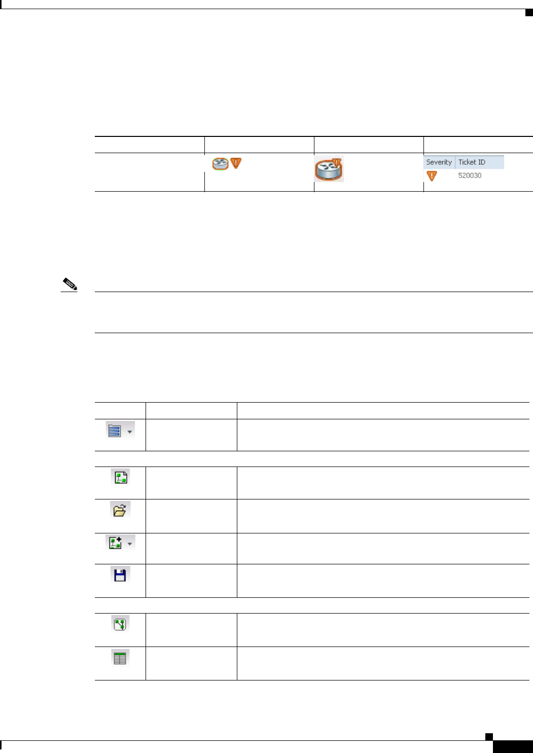
2-23
Cisco Prime Network 4.0 User Guide
OL-29343-01
Chapter 2 Working with the Prime Network Vision Client Prime Network Vision Toolbar
Tickets
Cisco Prime Network Vision displays an icon with a ticket to indicate the severity of the top-most alarm
on the ticket. The icons are the same as those used with network elements (see Table 2-5) and are
displayed in Cisco Prime Network Vision as follows:
Prime Network Vision Toolbar
The Prime Network Vision toolbar is context-sensitive and the options vary depending on your selection
in the application.
Note The functionality that a user can access in Prime Network Vision depends on the user role and the
security level of the scopes assigned to the user. For more information, see User Roles Required for
Working with Prime Network Vision Maps, page 5-2.
Table 2-13 identifies the toolbar buttons and describes the functions that are available in the Prime
Network Vision toolbar.
Value Navigation Pane Map Ticket Pane
Element with ticket of
Major severity
Table 2-13 Prime Network Vision Toolbar
Button Name Function
Open Network
Inventory Opens the Network Elements tab.
Map Options
New Map Creates a new map in the database.
Open Map Opens a map saved in the database using the Open dialog box.
Add to Map Adds an element to the map or to the subnetwork selected in the
navigation pane and displayed in the content pane.
Save Map
Appearance Saves the current map (the background and the location of devices)
to the database.
Viewing Options
Show Map View Displays the map view in the Prime Network Vision content pane
(the button toggles when selected or deselected).
Show List View Displays the list view in the Prime Network Vision content pane (the
button toggles when selected or deselected).

2-24
Cisco Prime Network 4.0 User Guide OL-29343-01
Chapter 2 Working with the Prime Network Vision Client
Prime Network Vision Toolbar
Show Links View Displays the links view in the Prime Network Vision content pane
(the button toggles when selected or deselected).
Overlay Tools
Choose Overlay
Type Chooses and displays an overlay of a specific type on top of the
elements displayed in the content pane in a map view.
Available overlay options are:
• Ethernet Service
• MPLS-TP Tunnel
• Network Clock
• Pseudowire
• VLAN
• VPLS
• VPN
• None—Removes the existing overlays.
Show Overlay /
Hide Overlay Displays or hides a previously defined overlay on top of the
elements displayed in the map view.
Note Overlays do not reflect changes that occur in the selected
service. As a result, the information in an overlay can
become stale.
Refresh Overlay Refreshes the overlay that was last selected.
Viewing Tools
Go to Parent Moves up one level in the navigation pane and content pane so you
can view different information.
Link Filter Opens the Link Filter dialog box, enabling you to display or hide
different types of links in the map and links views.
If a link filter is applied to the map, the Link Filter Applied button
is displayed instead.
Link Filter Applied Indicates a link filter is currently applied to the map and opens the
Link Filter dialog box so you can remove or modify the existing link
filter.
If no link filter is applied to the map, the Link Filter button is
displayed instead.
Overview Opens a window displaying an overview of the network.
Find Business Tag Opens the Find Business Tag dialog box, enabling you to find and
delete a business tag according to name, key, or type.
Table 2-13 Prime Network Vision Toolbar (continued)
Button Name Function
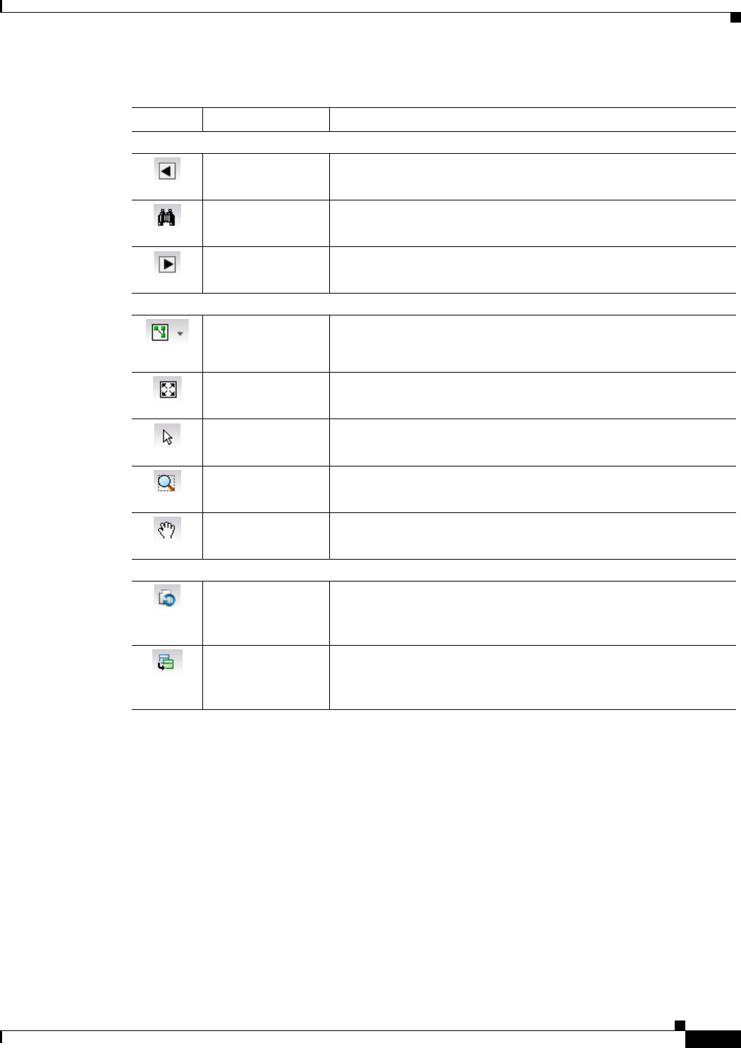
2-25
Cisco Prime Network 4.0 User Guide
OL-29343-01
Chapter 2 Working with the Prime Network Vision Client Prime Network Vision Menu Bar
Prime Network Vision Menu Bar
The following topics describe the options that are available in each Prime Network Vision menu:
• File Menu, page 2-26
• Edit Menu, page 2-27
• View Menu, page 2-27
• Node Menu, page 2-28
• Tools Menu, page 2-28
• Activation Menu, page 2-29
• Network Inventory Menu, page 2-29
Search Tools
Find Previous Finds the previous instance of the search string entered in the Find
in Map dialog box.
Find Opens the Find in Map dialog box, enabling you to find an element
in the map by its name or IP address.
Find Next Finds the next instance of the search string entered in the Find in
Map dialog box.
Map Zoom and Layout Tools
Layout Map Defines the way in which the elements are arranged in the Prime
Network Vision window: Circular, hierarchical, orthogonal, or
symmetric.
Fit in Window Fits all elements in the map in the content pane.
Normal Selection
Mode Activates the normal selection mode.
Zoom Selection
Mode Activates the zoom selection mode, which enables you to zoom in
on a section of the map by clicking and dragging the required area.
Pan Mode Activates the pan mode, which enables you to view different areas
of the map by clicking and dragging the map.
Application-Specific Tools
Open Activation Opens the Activation dialog box.
For more information, see the Cisco Prime Network 4.0
Customization Guide.
Activation History Opens the Activation History dialog box.
For more information, see the Cisco Prime Network 4.0
Customization Guide.
Table 2-13 Prime Network Vision Toolbar (continued)
Button Name Function

2-26
Cisco Prime Network 4.0 User Guide OL-29343-01
Chapter 2 Working with the Prime Network Vision Client
Prime Network Vision Menu Bar
• Reports Menu, page 2-30
• Window Menu, page 2-30
• Help Menu, page 2-30
Note The functionality that a user can access in Prime Network Vision depends on the user role and the
security level of the scopes assigned to the user. For more information, see User Roles Required for
Working with Prime Network Vision Maps, page 5-2. Also, the menus are context-sensitive and the
options vary depending on your selection in the application.
File Menu
Table 2-14 describes the options that are available in the Prime Network Vision File menu. For more
information, see Chapter 5, “Working with Prime Network Vision Maps.”
Table 2-14 File Menu Options
File Menu Option Description
New Map Creates a new empty map in the database.
Open Map Opens a map saved in the database using the Open dialog box.
Add to Map1Opens the Add dialog box and enables you to add any of the following to the map
or to the subnetwork selected in the navigation pane and displayed in the content
pane:
• Cross Connect
• Ethernet Service
• MPLS-TP Tunnel
• Network Element
• Pseudowire
• Unassociated Bridge
• VLAN
• VPLS
• VPN
Save Map1Saves the appearance of the map (the background and the location of devices) to
the database.
Save As Image1Saves the active map as an image and automatically displays the Save as Image
dialog box. Use this dialog box to save an image using a different file format or
name.
Print Preview1Displays how the map will look when it is printed.
Print1Prints the active map as displayed in the Print Preview dialog box.
Load MultiPath Loads a Cisco PathTracer multiple-path trace from a file that was previously
saved in Cisco PathTracer.

2-27
Cisco Prime Network 4.0 User Guide
OL-29343-01
Chapter 2 Working with the Prime Network Vision Client Prime Network Vision Menu Bar
Edit Menu
Table 2-15 identifies the options available in the Prime Network Vision Edit menu. For more
information, see Chapter 5, “Working with Prime Network Vision Maps.”
View Menu
Table 2-16 identifies the options available in the Prime Network Vision View menu. For more
information, see Using the Overview Window, page 5-14.
Close Closes the selected map or tab.
Exit Exits the Prime Network Vision application and saves the content pane.
1. This option is available only when a map is displayed in the content pane.
Table 2-14 File Menu Options (continued)
File Menu Option Description
Table 2-15 Edit Menu Options
Edit Menu Option Description
Find in Map Searches for a device in the map that contains the specified text in the name or
the IP address fields.
Find Business Tag Searches for business tag information in the database.
Resize This option is displayed only when element icons or aggregations are selected.
Displays the Resize dialog box, enabling you to specify the size of selected icons
or aggregations in the map, either by percentage or size.
Select All Selects all elements in the map.
Table 2-16 View Menu Options
View Menu Option Description
Layout Defines the way in which the map is displayed in the Prime Network Vision
content pane: Circular, hierarchical, orthogonal, or symmetric.
Overview Opens a window displaying an overview of the network map.
Zoom In Zooms in on the network map.
Zoom Out Zooms out of the network map.
Fit In Window Displays the entire network map in the content pane.
Normal Select Activates the normal selection mode. The selected option is dimmed.
Pan Activates the pan mode, which enables you to move around in a map by clicking
and dragging. The selected option is dimmed.
Zoom Selection Activates the zoom selection mode, which enables you to select an area in a map
to zoom in on by clicking and dragging. The selected option is dimmed.

2-28
Cisco Prime Network 4.0 User Guide OL-29343-01
Chapter 2 Working with the Prime Network Vision Client
Prime Network Vision Menu Bar
Node Menu
Table 2-17 describes the Node menu options.
Note Most of the functionality available in this menu is available only when an element icon or an aggregation
is selected in the navigation pane or a map.
Tools Menu
Table 2-18 describes the Tools menu options.
Table 2-17 Node Menu Options
Node Menu Option Description
Inventory Displays a dialog box that enables you to view the physical and logical inventory.
For physical inventory, you can view all the components of the device, such as
modules and ports. In addition, you can view the status of each component. For
logical inventory, you can view all the profiles and virtual channels or routing
tables of the device. For more information, see Chapter 3, “Viewing and
Managing NE Properties.”
Mark as A Side Starts the process of creating a new static link. This option is enabled when a
device, port, or unmanaged network is selected.
Mark as Z Side Launches the Add Static Link dialog box, enabling you to create a static link
between the two selected nodes. This option is enabled after a device, port, or
unmanaged network is selected and after the Mark as A Side option is selected.
Note If you select two ports, the Add Static Link dialog box is not displayed.
Properties Displays a dialog box enabling you to view the properties of the selected device,
such as the severity, IP address, and communication state. For more information,
see Chapter 3, “Viewing and Managing NE Properties.”
Table 2-18 Tools Menu Options
Tools Menu Option Description
Change User
Password Enables you to change the password used when logging into the Prime Network
client application suite. The change takes effect the next time you log into the
application.
Note The administrator can also change a user password in Cisco Prime
Network Administration.
Options Enables you to customize several of Prime Network’s options, such as whether
or not to load the content upon startup. For more information, see Adjusting the
Prime Network Vision GUI Client Settings, page 2-40.

2-29
Cisco Prime Network 4.0 User Guide
OL-29343-01
Chapter 2 Working with the Prime Network Vision Client Prime Network Vision Menu Bar
Activation Menu
Note Transaction Manager replaces the Prime Network Workflow and Action features in all new installations
of Prime Network 4.0. If you have upgraded to Prime Network 4.0, the Workflow and Activation features
are still available, but they will be deprecated in the future. We recommend that you use Transaction
Manager.
See the Cisco Prime Network 4.0 Customization Guide for more information about any of the options in
this menu.
Table 2-19 describes the Activation menu options.
Network Inventory Menu
Table 2-20 describes the Network Inventory menu options.
Change and Config
Mgmnt Displays the Prime Network Change and Configuration Management dashboard.
For more information, see the Chapter 4, “Device Configurations and Software
Images.”
Command Jobs Displays all Command Builder jobs that have been scheduled and their details.
For more information, see the Cisco Prime Network 4.0 Customization Guide.
Table 2-18 Tools Menu Options (continued)
Tools Menu Option Description
Table 2-19 Activation Menu Options
Activation Menu Option Description
Activation Opens the Activation dialog box.
Activation History Opens the Activation History dialog box.
Activation Modification Utility Opens the Activation Modification Utility dialog box.
Table 2-20 Network Inventory Menu Options
Network Inventory
Menu Option Description
Network Elements Displays a list of the available network elements in the Network Elements tab.
For more information, see Prime Network Vision Inventory Tabs, page 2-5.
Ethernet Flow
Domains Displays a list of the current Ethernet flow domains in the Ethernet Flow
Domains tab. For more information, see Viewing and Renaming Ethernet Flow
Domains, page 12-42

2-30
Cisco Prime Network 4.0 User Guide OL-29343-01
Chapter 2 Working with the Prime Network Vision Client
Prime Network Vision Menu Bar
Reports Menu
Table 2-21 describes the Reports menu options.
For more information about Report Manager and reports, see Chapter 10, “Working with Reports.”
Window Menu
The Prime Network Vision Window menu lists all maps open in the Prime Network Vision content pane,
enabling you to move between the maps. The menu also lists any network element inventory tabs that
are open.
Help Menu
Table 2-22 describes the Help menu options.
VTP Domains Displays a list of the current of the VLAN Trunk Protocol (VTP) domains in the
VTP Domains tab. For more information, see Viewing VLAN Trunk Group
Properties, page 12-68.
Virtual Machines Displays a list of the available virtual machines in the Virtual Machines tab. For
more information about virtual machines, see Viewing the Virtual Machines of a
Data Center, page 26-19.
Table 2-20 Network Inventory Menu Options (continued)
Network Inventory
Menu Option Description
Table 2-21 Reports Menu Options
Reports Menu Option Description
Report Manager Opens the Reports Manager window so you can create, run, and manage
reports.
Run Report Enables you to run standard or user-defined events, inventory, and network
service reports on demand.
Table 2-22 Help Menu Options
Help Menu Option Description
Cisco Prime
Network Vision
Help
Opens the online help for Prime Network Vision and Prime Network Events.
Icon Reference Opens a window that identifies and describes the icons and buttons used in Prime
Network Vision and Prime Network Events.
Cisco.com This option is unavailable.
About Cisco Prime
Network Vision Displays the Prime Network version and any additionally installed applications.

2-31
Cisco Prime Network 4.0 User Guide
OL-29343-01
Chapter 2 Working with the Prime Network Vision Client Prime Network Vision Right-Click Menus
Prime Network Vision Right-Click Menus
If you right-click a specific area, link, network element, device, or alarm in a Prime Network Vision
window, a context-sensitive right-click menu is displayed that contains options available for the selected
item or items.
Right-click menus are also available in many of the inventory and property windows. For example, if
you right-click an entry in a logical inventory table, you can view properties specific to that entry. The
options that are available depend on the window or table currently displayed and the item selected.
The menus are context-sensitive and the options vary according to your selection in the application. For
example, the right-click menus for network elements and aggregations are different.
Additional right-click options are displayed in the following situations:
• If Prime Network is installed as part of the Cisco Prime suite of applications, right-click menus in
Prime Network Vision include options for accessing the other Cisco Prime applications.
• If Prime Performance Manager is installed in your environment, Prime Network Vision includes
right-click options that allow you to generate device, interface, and VRF-related reports using Prime
Performance Manager.
• The Prime Network Vision installation includes a number of scripts. When these scripts are
installed, they are displayed as options in the right-click menus of the devices that support them. For
more information about these scripts, see Setting Up Devices and Validating Device Information,
page 1-4.
The functionality that you can access in Prime Network Vision depends on your user role and the security
level of the scopes that you can access. For more information, see User Roles Required for Working with
Prime Network Vision Maps, page 5-2.
See the following topics for the default options available in Prime Network Vision right-click menus:
• Map Right-Click Menu, page 2-32
• Element Right-Click Menu, page 2-32
• Aggregation Right-Click Menu, page 2-36
• Link Right-Click Menu, page 2-36
• List View Right-Click Menu, page 2-37
• Links View Right-Click Menu, page 2-39
• Ticket Right-Click Menu, page 2-40

2-32
Cisco Prime Network 4.0 User Guide OL-29343-01
Chapter 2 Working with the Prime Network Vision Client
Prime Network Vision Right-Click Menus
Map Right-Click Menu
The map right-click menu is displayed when you right-click anywhere on a map in the content pane and
no elements are selected.
Table 2-23 describes the map right-click menu options.
Element Right-Click Menu
The element right-click menu is displayed when you right-click an element in the navigation pane, the
content pane, or in the Network Elements inventory tab.
Note The element right-click menu is context-sensitive and the options vary depending on your selection in
the application. Also, some options might not be available if multiple elements are selected.
Table 2-24 describes the options available in the element right-click menu.
Table 2-23 Map Right-Click Menu Options
Option Description
Go to Parent Moves up one level in the navigation pane and content pane to enable you to view
different information.
Go to Root Moves to the root level in the navigation pane and content pane to enable you to
view different information.
Set Map
Background Displays a background image for the map in the content pane. For more
information, see Applying a Background Image, page 5-12.
Table 2-24 Element Right-Click Menu Options
Option Description
Add Associated VLAN Opens the Add Associated VLAN dialog box so that you can add an
associated VLAN to the selected VLAN. For more information, see Adding
an Associated VLAN, page 12-55.
Aggregate Groups the selected devices into an aggregation in the Prime Network Vision
content pane, and enables you to define a name for the new aggregation. For
more information, see Chapter 5, “Working with Prime Network Vision
Maps.”
Note You cannot aggregate service entities that exist within services. For
example, you cannot aggregate VRFs that exist in a VLAN.
Attach / Detach / Edit
Business Tag Allows you to perform the following actions:
• Attach a business tag to the selected network element.
• Detach a business tag from a network element.
• Edit a business tag for a network element.
Note The Detach and Edit options are displayed only when a business tag
is attached to a network element.
For more information, see Chapter 7, “Labeling NEs Using Business Tags.”

2-33
Cisco Prime Network 4.0 User Guide
OL-29343-01
Chapter 2 Working with the Prime Network Vision Client Prime Network Vision Right-Click Menus
Commands Enables you to launch any of the commands that are included with Prime
Network Vision.
For more information on the available commands and how to implement
them, see Configure Basic Device Settings: Name, DNS, NTP, RADIUS,
TACACs, ACLs, page 1-5.
Note Additional commands may be available for your devices. New
commands are often provided in Prime Network Device Packages,
which can be downloaded from the Prime Network software
download site. For more information on how to download and install
DPs and enable new commands, see the information on “Adding
Additional Device (VNE) Support” in the Cisco Prime Network 4.0
Administrator Guide.
Config Mgmnt This option is available only if Prime Network Change and Configuration
Management is installed.
Displays the Configuration Management page for the selected device in
Prime Network Change and Configuration Management.
For more information, see Chapter 4, “Device Configurations and Software
Images.”
Delete Deletes the selected item from the map.
Disaggregate Ungroups the devices in the selected aggregation in the navigation and map
panes. For more information, see Chapter 5, “Working with Prime Network
Vision Maps.”
Note This option is available only when an aggregation is selected in the
navigation pane or map.
Edit Move the selected virtual router to the location you specify.
Filter Tickets Displays only those tickets that have the selected VNE as the root cause.
This option is available only for VNEs that have not been deleted by Prime
Network Administration.
Hide Connected
Devices Hides the devices for sites with one or more connected devices.
Image Mgmnt This option is available only if Prime Network Change and Configuration
Management is installed.
Displays the Image Management page for the selected device in Prime
Network Change and Configuration Management.
For more information, see Chapter 4, “Device Configurations and Software
Images.”
Inventory Displays a window enabling you to view the physical and logical inventory.
For physical inventory, you can view all the components of the device, such
as the modules, ports, and its IP address or configured VLANs. In addition,
you can view the status of each component. For logical inventory, you can
view all the profiles and VC tables of the device. For more information, see
Chapter 3, “Viewing and Managing NE Properties.”
Table 2-24 Element Right-Click Menu Options (continued)
Option Description

2-34
Cisco Prime Network 4.0 User Guide OL-29343-01
Chapter 2 Working with the Prime Network Vision Client
Prime Network Vision Right-Click Menus
Launch external
applications Starts an external application or tool that has been configured for access via
the right-click menu. For more information, see the Cisco Prime Network 4.0
Customization Guide.
Management Contains the following submenu options:
• Command Builder—Defines commands and scripts using the Prime
Network Command Builder tool (Configurator security level required).
• Soft Properties Management—Extends VNEs by adding SNMP MIB or
Telnet/SHH/TL-1 properties to the device’s collected information model
using the Prime Network Soft Properties Manager (Administrator
security level required).
For more information about Command Builder and Soft Properties Manager,
see the Cisco Prime Network 4.0 Customization Guide.
Modify Displays the Modify dialog box so that you can change the selected item’s
name, description, or icon.
Open Relevant Maps Displays the Open Map dialog box so that you can view and open maps that
contain the selected element.
PathTracer Launches a path trace from the selected item.
Poll Now Polls the selected element.
Properties Displays the properties of the selected item, such as the IP address and
system name. In addition, you can open the VNE Properties dialog box and
manage VNE properties. For more information, see Chapter 3, “Viewing and
Managing NE Properties.”
Remove from Map Removes the selected device and all its children from the map (navigation
pane and content pane). The device that has been removed is still maintained
in the network.
Rename Renames the selected item.
Resize Enables you to resize an object on the map by percentage or size.
Run Report Enables you to run standard or user-defined events, inventory, and network
service reports on demand.
Save as New Map Creates a new map and places the selected aggregation as the root, while
leaving the original map intact.
Script names Launches available activation and configuration scripts. This can include the
commands documented in Setting Up Devices and Validating Device
Information, page 1-4.
Show as Aggregation /
Thumbnail Displays the selected aggregation as a single entity or as a collection of
items.
The options toggle, depending on whether the aggregation is in a thumbnail
or aggregated view.
Show CE Device Displays devices for sites or LCPs with one or more hidden, connected
devices.
Table 2-24 Element Right-Click Menu Options (continued)
Option Description

2-35
Cisco Prime Network 4.0 User Guide
OL-29343-01
Chapter 2 Working with the Prime Network Vision Client Prime Network Vision Right-Click Menus
Tools The Tools option contains the following choices:
• CPU Usage—Displays memory and CPU usage information for a device
or network element.
• Ping—Pings the device from the client station.
• Telnet—Communicates with the device using the Telnet window from
the client station.
Note If you are using a Windows 7 system and want to use the Prime
Network Telnet option, you need to set up Telnet on the Windows 7
system as follows:
- For Windows 7 32-bit systems, enable the Windows Telnet Client
to use the Prime Network Telnet option.
- For Windows 7 64-bit systems, a solution is available on the
Cisco Developer Network at
http://developer.cisco.com/web/prime-network/forums/-/message_b
oards/message/2780108.
Topology The Topology option enables you to add:
• A static link between two devices.
• A static topology between a device and an unmanaged network.
• A tunnel to a VPN.
When working with static links, the following submenu options enable you
to define the A Side and Z Side of the link:
• Mark as A Side
• Mark as Z Side
When working with VPNs in VPN Service View, the Add Tunnel submenu
option allows you define and configure tunnels.
VNE Tools Contains the following submenu options:
• Poll Now—Updates the VNE information.
• Stop VNE—Stops the VNE.
• Start VNE—Starts the VNE.
For more information, see Chapter 3, “Viewing and Managing NE
Properties.”
Table 2-24 Element Right-Click Menu Options (continued)
Option Description

2-36
Cisco Prime Network 4.0 User Guide OL-29343-01
Chapter 2 Working with the Prime Network Vision Client
Prime Network Vision Right-Click Menus
Aggregation Right-Click Menu
The aggregation right-click menu is displayed when you right-click an aggregation in a map.
Table 2-25 describes the aggregation right-click menu options.
Link Right-Click Menu
The Link right-click menu is displayed when you right-click a link in the map view. For more
information, see Chapter 6, “Working with Links.”
Table 2-26 describes the link right-click menu options.
Table 2-25 Aggregation Right-Click Menu Options
Option Description
Aggregate Groups the selected aggregations into an aggregation in the Prime Network
Vision content pane, and enables you to define a name for the new aggregation.
For more information, see Chapter 5, “Working with Prime Network Vision
Maps.”
Disaggregate Ungroups the selected aggregation in the navigation pane and map in the Prime
Network Vision window. All the aggregations in the selected node move up one
level, and the original aggregation is removed. For more information, see
Chapter 5, “Working with Prime Network Vision Maps.”
Rename Renames the selected aggregation.
Resize Defines the size of selected aggregations in a map according to one of four sizes
or according to a percentage of the current size.
Remove from Map Removes the selected aggregation and all its children from the navigation pane
and the map.
Save as New Map Creates a new map and places the selected aggregation as the root, while leaving
the original map intact.
Run Report Enables you to run standard or user-defined events, inventory, and network
service reports.
Show as
Aggregation /
Thumbnail
Displays the aggregation as a single entity or as a collection of items.
The options toggle, depending on whether the aggregation is in a thumbnail or
aggregated view.
Delete Deletes the selected item.
This option is available when the item is marked with the reconciliation icon.
Table 2-26 Link Right-Click Menu Option
Option Description
Properties Displays the properties of the selected link.

2-37
Cisco Prime Network 4.0 User Guide
OL-29343-01
Chapter 2 Working with the Prime Network Vision Client Prime Network Vision Right-Click Menus
List View Right-Click Menu
The list view right-click menu is displayed when you right-click an entry in the Network Elements tab
in the list view table. For more information, see List View, page 2-12.
Table 2-27 describes the list view right-click menu options.
Table 2-27 List View Right-Click Menu Options - Network Elements Tab
Option Description
Inventory Displays a window enabling you to view the physical and logical inventory.
For physical inventory, you can view all the components of the device, such
as the modules, ports, and its IP address or configured VLANs. In addition,
you can view the status of each component. For logical inventory, you can
view all the profiles and VC tables of the device. For more information, see
Chapter 3, “Viewing and Managing NE Properties.”
Attach / Detach /
Edit Business Tag Allows you to perform the following actions:
• Attach a business tag to the selected element.
• Remove a business tag from the selected element.
• Edit an existing business tag for the selected element.
Note The Detach and Edit options are available only when a business tag
is attached to a link.
For more information, see Chapter 7, “Labeling NEs Using Business Tags.”
Config Mgmnt Displays the Configuration Management page for the selected device in
Prime Network Change and Configuration Management.
For more information, see Chapter 4, “Device Configurations and Software
Images.”
Image Mgmnt Displays the Image Management page for the selected device in Prime
Network Change and Configuration Management.
For more information, see Chapter 4, “Device Configurations and Software
Images.”
Run Report Enables you to run standard or user-defined events, inventory, and network
service reports.
Show Only
Selected Rows Displays only the rows that you select.
Show All Rows Displays all table rows that meet the current filtering criteria.

2-38
Cisco Prime Network 4.0 User Guide OL-29343-01
Chapter 2 Working with the Prime Network Vision Client
Prime Network Vision Right-Click Menus
Tools Contains the following submenu options:
• CPU Usage—Displays memory and CPU usage information for a device
or network element.
• Ping—Pings the device from the client station.
• Telnet—Communicates with the device using the Telnet window from
the client station.
Note If you are using a Windows 7 system and want to use the Prime
Network Telnet option, you need to set up Telnet on the Windows 7
system as follows:
- For Windows 7 32-bit systems, enable the Windows Telnet Client
to use the Prime Network Telnet option.
- For Windows 7 64-bit systems, a solution is available on the
Cisco Developer Network at
http://developer.cisco.com/web/prime-network/forums/-/message_b
oards/message/2780108.
Topology Enables you to add:
• A static link between two devices.
• A static topology between a device and an unmanaged network.
• A tunnel to a VPN.
When working with static links, the following submenu options enable you
to define the A Side and Z Side of the link:
• Mark as A Side
• Mark as Z Side
When working with VPNs in VPN Service View, the Add Tunnel submenu
option allows you define and configure tunnels.
Launch external
applications Launches external applications or tools, such as an SSH client. See the
Cisco Prime Network 4.0 Customization Guide.
Properties Displays the properties of the selected item, such as the IP address and
system name. In addition, you can open the VNE Properties dialog box and
manage VNE properties. For more information, see Chapter 3, “Viewing and
Managing NE Properties.”
Commands Enables you to launch any of the commands that are included with Prime
Network Vision. For a complete list of the available commands, see Setting
Up Devices and Validating Device Information, page 1-4.
Note Additional commands may be available for your devices. New
commands are often provided in Prime Network Device Packages,
which can be downloaded from the Prime Network software
download site. For more information on how to download and install
DPs and enable new commands, see the information on “Adding
Additional Device (VNE) Support” in the Cisco Prime Network 4.0
Administrator Guide.
Table 2-27 List View Right-Click Menu Options - Network Elements Tab (continued)
Option Description

2-39
Cisco Prime Network 4.0 User Guide
OL-29343-01
Chapter 2 Working with the Prime Network Vision Client Prime Network Vision Right-Click Menus
Links View Right-Click Menu
The links view right-click menu is displayed when you right-click a link in the links view table. For more
information, see Chapter 6, “Working with Links.”
Table 2-28 describes the links view right-click menu options.
Script names Launches available activation and configuration scripts. This includes the
commands documented throughout this guide and those you create using
Command Manager and Command Builder. A list of scripts is provided in
Cisco Prime Network 4.0 Supported VNEs - Addendum.
Management Contains the following submenu options:
• Command Builder—Defines commands and scripts using the Prime
Network Command Builder tool (Configurator security level required).
• Soft Properties Management—Extends VNEs by adding SNMP MIB or
Telnet/SHH/TL-1 properties to the device’s collected information model
using the Prime Network Soft Properties Manager (Administrator
security level required).
For more information about Command Builder and Soft Properties Manager,
see the Cisco Prime Network 4.0 Customization Guide.
VNE Tools Contains the following submenu options:
• Poll Now—Updates the VNE information.
• Stop VNE—Stops the VNE.
• Start VNE—Starts the VNE.
For more information, see Chapter 3, “Viewing and Managing NE
Properties.”
Table 2-27 List View Right-Click Menu Options - Network Elements Tab (continued)
Option Description
Table 2-28 Links View Right-Click Menu Options
Option Description
Attach Business
Tag Attaches a business tag to the selected link. For more information, see Chapter 7,
“Labeling NEs Using Business Tags.”
Detach/Edit
Business Tag Detaches or edits a business tag from the selected link. For more information, see
Chapter 7, “Labeling NEs Using Business Tags.”
The Detach and Edit options are available only when a business tag is attached
to a link.
Select Link in Map Highlights the selected link in the content pane.
Show Only
Selected Rows Displays only the rows that you select.
Show All Rows Displays all table rows that meet the current filtering criteria.
Properties Displays the properties of the selected link.

2-40
Cisco Prime Network 4.0 User Guide OL-29343-01
Chapter 2 Working with the Prime Network Vision Client
Adjusting the Prime Network Vision GUI Client Settings
Ticket Right-Click Menu
The Ticket right-click menu is displayed when you right-click a ticket in the ticket pane. The Ticket
right-click menu enables you to view ticket properties and highlights the links or elements that are
affected by a ticket. The Ticket menu also enables you to acknowledge, clear, and remove a ticket. For
more information, see Chapter 9, “Working with Tickets in Prime Network Vision.”
Table 2-29 describes the ticket right-click menu options.
Adjusting the Prime Network Vision GUI Client Settings
Table 2-30 lists the options for changing the GUI client display and audio settings, and for controlling
the startup view and event history. You can adjust these settings by selecting Tools > Options from the
main menu.
Table 2-29 Ticket Right-Click Menu Options
Option Description
Acknowledge Acknowledges that the ticket is being handled; the ticket is displayed as true in
the ticket pane. Acknowledging an alarm removes the alarm icon from the device
icon. Multiple tickets can be acknowledged at the same time.
Clear Approves the reported faulty ticket and clears the faulty networking entity from
Prime Network. The ticket is displayed as Clear in the ticket pane.
Note When a Card Out or Link Down alarm occurs, the relevant information is
displayed in the inventory and maintained in the VNE.
Remove Removes the ticket and all its active subtickets from the ticket pane (this option
is only available after the ticket has been cleared). The deleted tickets can be
viewed using Cisco Prime Network Events. Multiple tickets can be removed at
the same time.
Note When a ticket is removed, the information is no longer displayed in the
inventory and is removed from the VNE.
Clear and Remove Approves the reported faulty ticket and clears the faulty networking entity from
Prime Network. In addition, the ticket and all its active subtickets are removed
from the ticket pane.
Find Affected
Elements Finds any elements affected by the selected ticket:
• If only one element is affected, it is selected in the Prime Network navigation
pane and content area.
• If multiple elements are affected, they are displayed in the Affected
Elements window.
Show Only
Selected Rows Displays only the rows that you select.
Show All Rows Displays all table rows that meet the current filtering criteria.
Properties Displays the Ticket Properties dialog box, enabling you to view ticket
information, including impact analysis details of the affected parties and
correlated alarms. See Viewing Ticket Properties, page 9-9.

2-41
Cisco Prime Network 4.0 User Guide
OL-29343-01
Chapter 2 Working with the Prime Network Vision Client Adjusting the Prime Network Vision GUI Client Settings
Table 2-30 Options for Changing Prime Network Vision GUI Client
Field Description
Startup
Load
Workspace on
Startup
Open to content pane on login. Check the box if you do not want to view the content pane
when you log in.
Display Tab
Preferences Map Labels
Font Size Font size for map labels (26, 28, 30, 32, and 34; 30 is the default).
Severity Show Severity
Text
(e.g. [3M+]
List severity levels in the navigation pane and maps, using the formula
described in New Ticket Propagation, page 2-18. Check the box if you
do want to see severity text.
Show
Acknowledged View both acknowledged and unacknowledged alarms in the network
element display name. Check the box if you do want to see both
unacknowledged and acknowledged alarms.
Show
Propagated View propagated alarms on the specific entity. Propagated alarms are
those that occur on other NEs. Check the box if you do want to see
propagated alarms.
Display Name How NE name is displayed:
• Do not use Business Tag—Display NE name only
• Add Business Tag to name—Display NE name and business tag.
• Replace name with Business Tag—Display business tag only (when a subscriber is
attached to a port, the subscriber name is also added)
Audio Tab
Enable Audio
Response for
Alarm
Audio notification settings. Check the box if you do want a sound to be issued when an
alarm is triggered.
Critical The .wav file to use for critical alarms.
Major The .wav file to use for major alarms.
Minor The .wav file to use for minor alarms.
Loop Sound on
Critical Alarm If critical alarm sound should sound continuously when a critical alarm is triggered.
Check the box if you do want a sound to play continuously.
Events Tab
Events History
Size in Hours Maximum age of events to display in the Network Events and Provisioning Events tab in
the inventory window (see Ticket and Events Pane, page 3-15). If you only want to see
active events, enter 0 (zero). The default (6 hours) is controlled from the Prime Network
Administration GUI client.
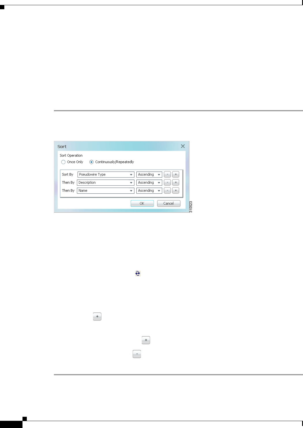
2-42
Cisco Prime Network 4.0 User Guide OL-29343-01
Chapter 2 Working with the Prime Network Vision Client
Filtering and Sorting Tabular Content
Filtering and Sorting Tabular Content
For tables with extensive data, you can view all of the information in a table cell by hovering your mouse
cursor over the cell. These topics explain how to sort and filter tabular information.
Sorting Tables
Sorting a table lets you arrange existing data in various ways, while filtering a table only displays the
information that matches the filter.
To sort a table using the Sort Table Values option:
Step 1 In the table toolbar, click Sort Table Values. The Sort dialog box is displayed.
Figure 2-11 Sort Dialog Box
Step 2 In the Sort Operation field, specify the frequency of the sort operation:
• Only Once—Sorts the information in the table only once according to the specified criteria. When
this option is selected, newly added rows will always be listed at the bottom of the table, regardless
of their sort criteria value. Also, if an existing row's value changes, the row will remain where it is.
• Continuously/Repeatedly—Sorts the information in the table continuously according to the
specified criteria.
If you select this option, the icon is displayed next to the selected column heading.
Step 3 In the Sort By field, specify the first sort criterion:
a. In the first drop-down list, choose the column to use for the first sort criterion.
b. In the second drop-down list, choose Ascending or Descending to indicate the sort order.
Step 4 If needed, click to add another sort criterion.
Step 5 Adjust the sort criteria as needed:
• To add additional criteria, click .
• To remove a criterion, click .
Step 6 Click OK to sort the table using the specified criteria.

2-43
Cisco Prime Network 4.0 User Guide
OL-29343-01
Chapter 2 Working with the Prime Network Vision Client Filtering and Sorting Tabular Content
Filtering Tables
Filtering can be extremely helpful when working with tables that contain many entries.
Note If you load a table with many entries, (for example, thousands of entries), it can take a while for the
complete table to load. The filtering options in the table toolbar are unavailable until the table has
completely loaded.
You can tell a table is being filtered if any filter details are displayed in the status line below the table or
when you hover the mouse cursor over the filter button.
To define a filter:
Step 1 In the toolbar above the table, click Filter. The Filter dialog box is displayed as shown in Figure 2-12.
Figure 2-12 Table Filter Dialog Box
Step 2 In the Match drop-down list, choose the rule for including items that meet the specified criteria:
• All—All of the following criteria are to be met.
• Any—Any of the following criteria are to be met.
Step 3 For each criterion, specify the following information:
a. In the first drop-down list, choose the primary match category. The drop-down list contains all
columns in the current table.
b. In the second drop-down list, choose the rule to use for this criterion.
c. The third field either lists the available values or allows you to enter text using a drop-down list or
free text.
Table 2-31 Table Toolbar Options
Option Name Description
Filter Filters the information displayed in the table by the
criteria you specify.
For more information, see Filtering Tables,
page 2-43.
Clear Filter Clears the existing filter.

2-44
Cisco Prime Network 4.0 User Guide OL-29343-01
Chapter 2 Working with the Prime Network Vision Client
Filtering and Sorting Tabular Content
Tip You can use the “Greater than” or “Less than” rule with a string for filtering. For example, if you
want to include all interfaces above Ethernet0/0/3, you can select Greater than and enter the
string Ethernet0/0/3 to view interfaces Ethernet0/0/4, Ethernet0/0/5, and so on.
Step 4 Click to add another criterion for this filter.
Step 5 Add additional criteria as required. To remove a criterion, click .
Step 6 When you have specified all criteria for the filter, click OK.
The table data is displayed using the defined filter.
Step 7 To clear a filter, click Clear Filter in the table toolbar.
The table is refreshed and all entries are displayed.

CHAPTER
3-1
Cisco Prime Network 4.0 User Guide
OL-29343-01
3
Viewing and Managing NE Properties
The following topics describe the user access roles required to use Cisco Prime Network Vision (Prime
Network Vision) and how to view network element physical and logical properties in any mapped
network:
• User Roles Required to Work with Prime Network Vision, page 3-1
• Information Available in Element Icons, page 3-3
• Viewing the Properties of a Network Element, page 3-6
• Inventory Window, page 3-9
• Checking VNE Connectivity and Communication Status, page 3-16
• Viewing the Physical Properties of a Device, page 3-19
• Working with Ports, page 3-23
• Viewing the Logical Properties of a Network Element, page 3-27
• Viewing Device Operating System Information, page 3-31
• Running an Activation from the Activation Menu, page 3-34
Note Prime Network Vision maintains continuous, real-time discovery of all the physical and logical entities
of the network inventory and the relationships among them. The Prime Network Vision distributed
system inventory automatically reflects every addition, deletion, and modification that occurs in the
network.
User Roles Required to Work with Prime Network Vision
This topic identifies the roles that are required to work with Prime Network Vision. Prime Network
determines whether you are authorized to perform a task as follows:
• For GUI-based tasks (tasks that do not affect elements), authorization is based on the default
permission that is assigned to your user account.
• For element-based tasks (tasks that do affect elements), authorization is based on the default
permission that is assigned to your account. That is, whether the element is in one of your assigned
scopes and whether you meet the minimum security level for that scope.
For more information on user authorization, see the Cisco Prime Network 4.0 Administrator Guide.

3-2
Cisco Prime Network 4.0 User Guide OL-29343-01
Chapter 3 Viewing and Managing NE Properties
User Roles Required to Work with Prime Network Vision
The following tables identify the tasks that you can perform:
• Table 3-1 identifies the tasks that you can perform if a selected element is not in one of your
assigned scopes.
• Table 3-2 identifies the tasks that you can perform if a selected element is in one of your assigned
scopes.
By default, users with the Administrator role have access to all managed elements. To change the
Administrator user scope, see the topic on device scopes in the Cisco Prime Network 4.0 Administrator
Guide.
Table 3-1 Default Permission/Security Level Required for Prime Network Vision Functions - Element Not in User’s
Scope
Task Viewer Operator OperatorPlus Configurator Administrator
View maps XXXXX
View network element properties — — — — X
View network element properties in logical
and physical inventory ————X
View port status and properties — — — — X
View VNE properties — — — — X
Open the Port Utilization Graph — — — — X
Enable and disable port alarms — — — — X1
View tickets in inventory window — — — — X
View network events in inventory window — — — — X
View provisioning events in inventory
window ————X
Create activation wizards — — — — —
Preview and perform activations and
deactivations —————
View activation details and output — — — — X
Search for activations — — — — X

3-3
Cisco Prime Network 4.0 User Guide
OL-29343-01
Chapter 3 Viewing and Managing NE Properties Information Available in Element Icons
Information Available in Element Icons
Element icons in Prime Network Vision maps display different amounts of information according to their
size as shown in Table 2-2. Table 3-3 identifies the information that is available for different types of
elements for the four icons sizes.
Table 3-2 Default Permission/Security Level Required for Prime Network Vision Functions - Element in User’s Scope
Task Viewer Operator OperatorPlus Configurator Administrator
View maps XXXXX
View network element properties X X X X X
View network element properties in logical
and physical inventory XXXXX
View port status and properties — X X X X
View VNE properties X X X X X
Open the Port Utilization Graph X X X X X
Enable and disable port alarms — — — X1
1. To enable and disable port alarms on a device, the Administrator scope level must also be configured for that device.
X1
View tickets in inventory window X X X X X
View network events in inventory window X X X X X
View provisioning events in inventory
window XXXXX
Create activation wizards — X X X X
Preview and perform activations and
deactivations ——— X X
View activation details and output X X X X X
Search for activations — X X X X
Table 3-3 Information Displayed in Element Icons by Size
Element Type
Icon Size
Tiny (Dot) Normal Large Huge
Aggregation Color representing
the associated
alarm severity
Name Name in card title Name in card title
Bridge Color representing
the associated
alarm severity
Name • Name in card title and body
• Number of Ethernet flow
points
• Name in card title and body
• Number of Ethernet flow
points
EFP cross-connect Color representing
the associated
alarm severity
Name Name in card title Name in card title

3-4
Cisco Prime Network 4.0 User Guide OL-29343-01
Chapter 3 Viewing and Managing NE Properties
Information Available in Element Icons
Ethernet flow
point Color representing
the associated
alarm severity
Name • Name in card title
• Type, such as Trunk, Access,
Dot1Q Tunnel, and so on
• Match criteria
• Name in card title
• Type, such as Trunk, Access,
Dot1Q Tunnel, and so on
• Match criteria
Ethernet service Color representing
the associated
alarm severity
Name • Name in card title
• Number of edge EFPs
• Name in card title
• Number of edge EFPs
EVC Color representing
the associated
alarm severity
Name • Name in card title
• Number of instances of
domains (VPLS, EoMPLS,
bridge, or cross-connect) with
a maximum of three lines
• Name in card title
• Number of instances of
domains (VPLS, EoMPLS,
bridge, or cross-connect) with
a maximum of four lines
LSP Endpoint
(Working or
Protected)
Color representing
the associated
alarm severity
Name • Name in card title
• Bandwidth
• Name in card title
• Bandwidth
• Attach Business Tag button
• Properties button
LSP Midpoint Color Name • Name in card title
• Forward bandwidth
• Reverse bandwidth
• Reverse in and out labels
• Name in card title
• Forward bandwidth
• Reverse bandwidth
• Reverse in and out labels
• Attach Business Tag button
• Inventory button
• Properties button
MPLS-TP Tunnel Color representing
the associated
alarm severity
Name Name in card title and body • Name in card title and body
• Attach Business Tag button
• Properties button
MPLS-TP Tunnel
Endpoint Color representing
the associated
alarm severity
Name • Name in card title and body
• Tunnel identifier
• Name in card title and body
• Tunnel identifier
• Attach Business Tag button
• Inventory button
• Properties button
Table 3-3 Information Displayed in Element Icons by Size (continued)
Element Type
Icon Size
Tiny (Dot) Normal Large Huge

3-5
Cisco Prime Network 4.0 User Guide
OL-29343-01
Chapter 3 Viewing and Managing NE Properties Information Available in Element Icons
Network element Color representing
the associated
alarm severity
Name • Name in card title
• Element model
• IP address
• Software version
• Name in card title
• Element model
• IP address
• Software version
• Inventory button
• Filter Tickets button
• Attach Business Tag button
Pseudowire Color representing
the associated
alarm severity
Name Name in card title and body • Name in card title and body
• Attach Business Tag button
• Properties button
Pseudowire edge Color representing
the associated
alarm severity
Name • Name in card title
• Local IP address
• Peer IP address
• Name in card title
• Local IP address
• Peer IP address
• Attach Business Tag button
• Inventory button
• Properties button
VLAN Color representing
the associated
alarm severity
Name Name in card title and body • Name in card title
• Name in card body
• Number of switching entities
• Number of edge EFPs
VPLS Color representing
the associated
alarm severity
Name • Name in card title
• Number of access EFPs
• Number of access pseudowires
• Number of VPLS forwards
• Name in card title
• Number of access EFPs
• Number of access pseudowires
• Number of VPLS forwards
VPLS Forward Color representing
the associated
alarm severity
Name • Name in card title
• VPN identifier
• Number of core pseudowires
• Name in card title
• VPN identifier
• Number of core pseudowires
VPN Color representing
the associated
alarm severity
Name Name in card title and body • Name in card title and body
• Attach Business Tag button
• Properties button
Table 3-3 Information Displayed in Element Icons by Size (continued)
Element Type
Icon Size
Tiny (Dot) Normal Large Huge
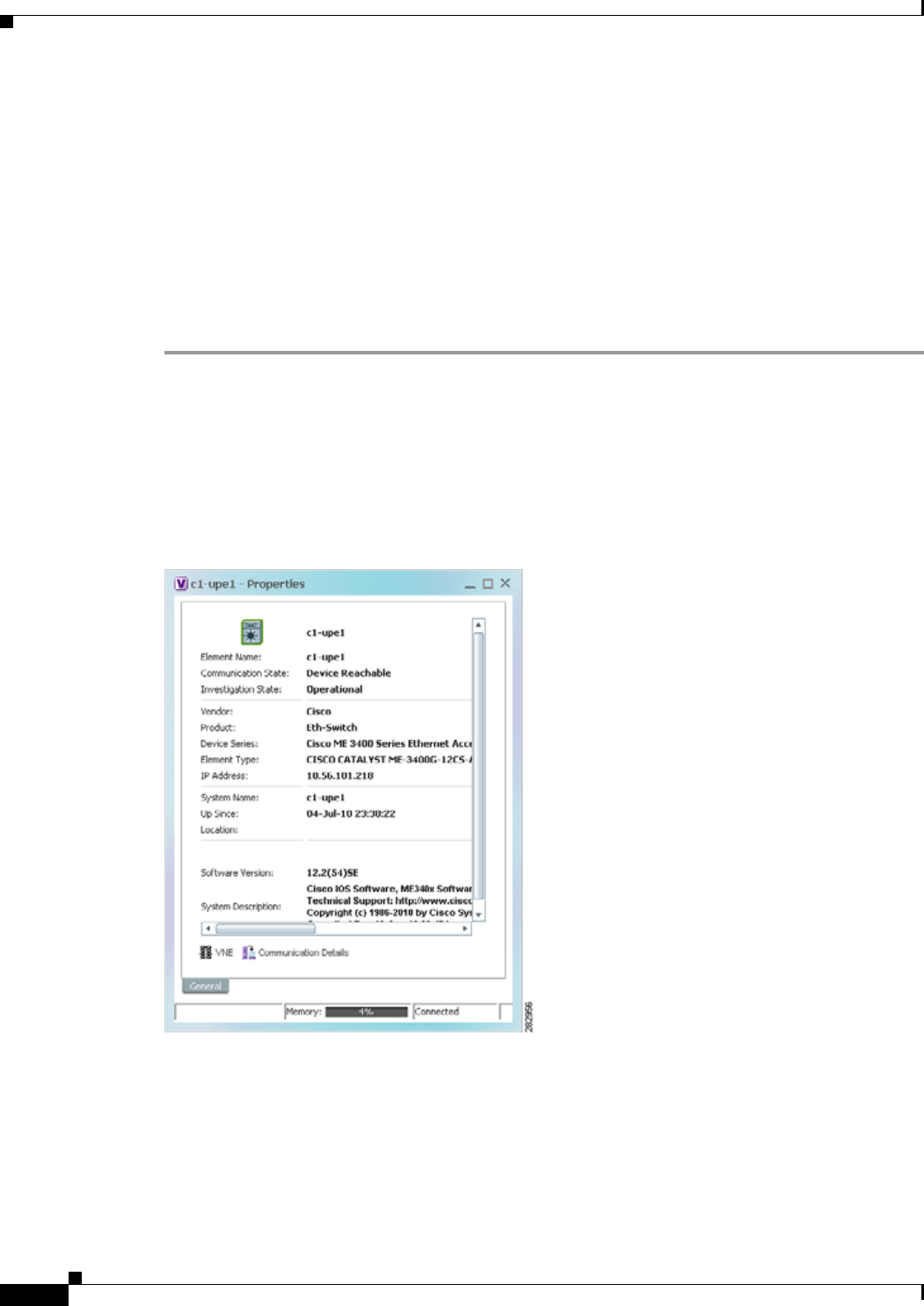
3-6
Cisco Prime Network 4.0 User Guide OL-29343-01
Chapter 3 Viewing and Managing NE Properties
Viewing the Properties of a Network Element
Viewing the Properties of a Network Element
You can view the general information about a selected network element in the Prime Network Vision
map view and view more detailed information by viewing the Properties window for the selected
element.
You can also perform NE configuration tasks such as changing the NE host name, configuring SNMP
settings, adding and managing SNMP traps, and managing other NE server settings (DNS, NTP,
RADIUS, TACACs and so forth) using basic commands that are launched from right-click contextual
menus. The commands are described in Setting Up Devices and Validating Device Information,
page 1-4.
Step 1 To view general information about a network element, hover your mouse cursor over the NE icon, and
use the mouse scroll to zoom in and out.
Step 2 For more detail, open the Properties (inventory) window, double-click the icon.
Depending on your selection, either the Properties window or inventory window is displayed with the
inventory window providing slightly more information than the Properties window. Figure 3-1 shows the
Properties window.
Figure 3-1 Properties Window
Table 3-4 describes the information displayed in both the Properties and inventory windows.

3-7
Cisco Prime Network 4.0 User Guide
OL-29343-01
Chapter 3 Viewing and Managing NE Properties Viewing the Properties of a Network Element
Table 3-4 Properties and Inventory Windows
Field Description
General Tab
Element icon Icon representing the element in Prime Network Vision and
displaying the current color associated with the element operational
health. For more information on severity colors, see Prime Network
Vision Status Indicators, page 2-17.
The icon might include a badge that indicates an alarm or another
item of interest associated with the element. For more information
about badges, see Network Element Badges, page 3-8.
Element Name Name assigned to the element for ease of identification.
Communication State Ability of the VNE to reach the network element and other
components in Prime Network. For more information about
communication states, see the Cisco Prime Network 4.0
Administrator Guide.
Investigation State Level of network element discovery that has been performed or is
being performed by the VNE. For more information about
investigation states, see the Cisco Prime Network 4.0 Administrator
Guide.
Vendor Vendor name, as defined in the device MIB.
Product Product name of the element, as defined in the device MIB; for
example, Router.
Device Series Product series that the device belongs to, such as Cisco 7600 Series
Routers.
Element Type Element model, such as Cisco 7606.
Serial Number1Serial number of the element.
CPU Usage1Percentage of CPU currently in use by the element.
Memory Usage1Amount of memory currently in use by the element.
IP Address IP address used for managing the element.
System Name Name of the device, as defined in the device MIB.
Up Since Date and time the element was last reset.
Contact Email address of the person responsible for the element.
Location Physical location of the element, as defined in the device MIB.
DRAM Usage1Percentage of available DRAM currently in use by the element.
Flash Device Size1Amount of flash memory available on the element.
NVRAM Size1Amount of NVRAM available on the element.
Software Version Software version running on the element.
Software Description Description of the system taken from the element.
Processor DRAM1Amount of DRAM currently in use by the element’s processor.
Sending Alarms1Whether or not the element is configured for sending alarms: True
or False.

3-8
Cisco Prime Network 4.0 User Guide OL-29343-01
Chapter 3 Viewing and Managing NE Properties
Viewing the Properties of a Network Element
Network Element Badges
Network elements and links can also display badges that are technology-specific, such as a Protected
LSP or an STP root. Table 3-5 describes some of the badges that are available in Prime Network Vision.
For more information, see the related topics.
Buttons
VNE Details Displays the VNE’s general properties, from where you can edit the
VNE’s properties, perform maintenance, configure polling rates,
and identify IP addresses for which SNMP syslog and trap events
are to be generated. For more information, see:
• VNE Properties Window (VNE Status Button in the content
pane of the Inventory Window), page 3-16
• Cisco Prime Network 4.0 Administrator Guide
VNE Status Displays details about the VNE’s communication and connectivity,
such as the status of device protocols and whether the device is
sending traps and syslogs. For more information, see VNE
Communication Status (VNE Details Button in the content pane of
the Inventory Window), page 3-17.
1. Displayed only in the inventory window.
Table 3-4 Properties and Inventory Windows (continued)
Field Description
Table 3-5 Network Element Badges
Icon Name Description Related Topic
Access gateway An MST or REP access gateway is
associated with the element. Viewing Access Gateway
Properties, page 12-19
Blocking The element associated with this badge
has a REP alternate port. Viewing REP Information in
VLAN Domain Views and
VLAN Overlays,
page 12-63
Clock service A clocking service is running on the
associated element. Applying a Network Clock
Service Overlay, page 20-48
Lock The associated network LSP is in lockout
state. Viewing MPLS-TP Tunnel
Properties, page 18-7
Multiple links One or more links is represented by the
visual link and at least one of the links
contains a badge.
Viewing REP Information in
VLAN Domain Views and
VLAN Overlays,
page 12-63

3-9
Cisco Prime Network 4.0 User Guide
OL-29343-01
Chapter 3 Viewing and Managing NE Properties Inventory Window
Inventory Window
Table 3-6 describes the tasks that you can perform from the inventory window and related topics.
Reconciliation The element with this badge is associated
with a network element that does not
exist. For example, the device
configuration has changed and a network
problem exists.
Some elements can be deleted only if
their components, such as EFPs, VPLS
forwards, or VRFs, display the
reconciliation icon.
Deleting a Business
Element, page 7-7
REP primary
blocking The element associated with this badge
has a REP primary port that is also
blocking.
Viewing REP Information in
VLAN Domain Views and
VLAN Overlays,
page 12-63
REP primary The element associated with this badge
has a REP primary port. Viewing REP Information in
VLAN Domain Views and
VLAN Overlays,
page 12-63
Redundancy service The element associated with this badge is
a backup pseudowire or a protected LSP. • Adding an MPLS-TP
Tunnel, page 18-5
• Viewing Pseudowire
Redundancy Service
Properties, page 12-96
STP root The element associated with this badge is
a STP root bridge or the root of an STP
tree.
Viewing STP Information in
VLAN Domain Views and
VLAN Overlays,
page 12-66
Table 3-5 Network Element Badges (continued)
Icon Name Description Related Topic
Table 3-6 Tasks Available from Inventory and Related Topics
Task Related Topic
Set up devices (server, ports, interfaces, and so
forth) and check device information using basic
commands (from a right-click menu)
Setting Up Devices and Validating Device
Information, page 1-4
Add or remove links. Adding Static Links, page 6-15
Generate the Port Utilization graph for physical
ports. Generating a Port Utilization Graph, page 3-27
Manage the alarms being sent on a port. Working with Ports, page 3-23
Open Cisco PathTracer and launch a path trace. Using Cisco PathTracer to Diagnose Problems,
page 11-1

3-10
Cisco Prime Network 4.0 User Guide OL-29343-01
Chapter 3 Viewing and Managing NE Properties
Inventory Window
The inventory window also allows you to view technology-specific information. For more information
on viewing technology-specific information in logical inventory or physical inventory, see:
• Chapter 12, “Monitoring Carrier Ethernet Services”
• Chapter 13, “Monitoring Carrier Grade NAT Properties”
• Chapter 14, “Monitoring DWDM Properties”
• Chapter 15, “Monitoring Ethernet Operations, Administration, and Maintenance Tool Properties”
• Chapter 16, “Monitoring Y.1731 IPSLA Configuration”
• Chapter 17, “IPv6 and IPv6 VPN over MPLS”
• Chapter 18, “Monitoring MPLS Services”
• Chapter 19, “Viewing IP and MPLS Multicast Configurations”
• Chapter 20, “Monitoring MToP Services”
• Chapter 21, “Viewing and Managing SBCs”
• Chapter 22, “Monitoring AAA Configurations”
• Chapter 23, “Monitoring IP Pools”
• Chapter 24, “Monitoring BNG Configurations”
• Chapter 25, “Monitoring Mobile Technologies”
• Chapter 26, “Monitoring Data Center Configurations”
• Chapter 27, “Monitoring Cable Technologies”
• Chapter 28, “Monitoring ADSL2+ and VDSL2 Technology Enhancements”
To open the inventory window, do one of the following:
• If the element icon is at the largest size, click the Inventory icon.
• Double-click an item in the navigation pane or map.
• Right-click an element in the navigation pane or map and choose Inventory.
Figure 3-2 shows an example of an inventory window.
Open the Prime Network Command Builder to
create customized commands.
Cisco Prime Network 4.0 Customization Guide
Open the Prime Network Soft Properties Manager
to extend the amount of information displayed. Cisco Prime Network 4.0 Customization Guide
Check VNE properties and communication status
when inventory is incomplete or missing Checking VNE Connectivity and Communication
Status, page 3-16
View physical and logical inventory information. • Viewing the Physical Properties of a Device,
page 3-19
• Viewing the Logical Properties of a Network
Element, page 3-27
View tickets or events for a device, service, or
component. Ticket and Events Pane, page 3-15
Table 3-6 Tasks Available from Inventory and Related Topics (continued)
Task Related Topic
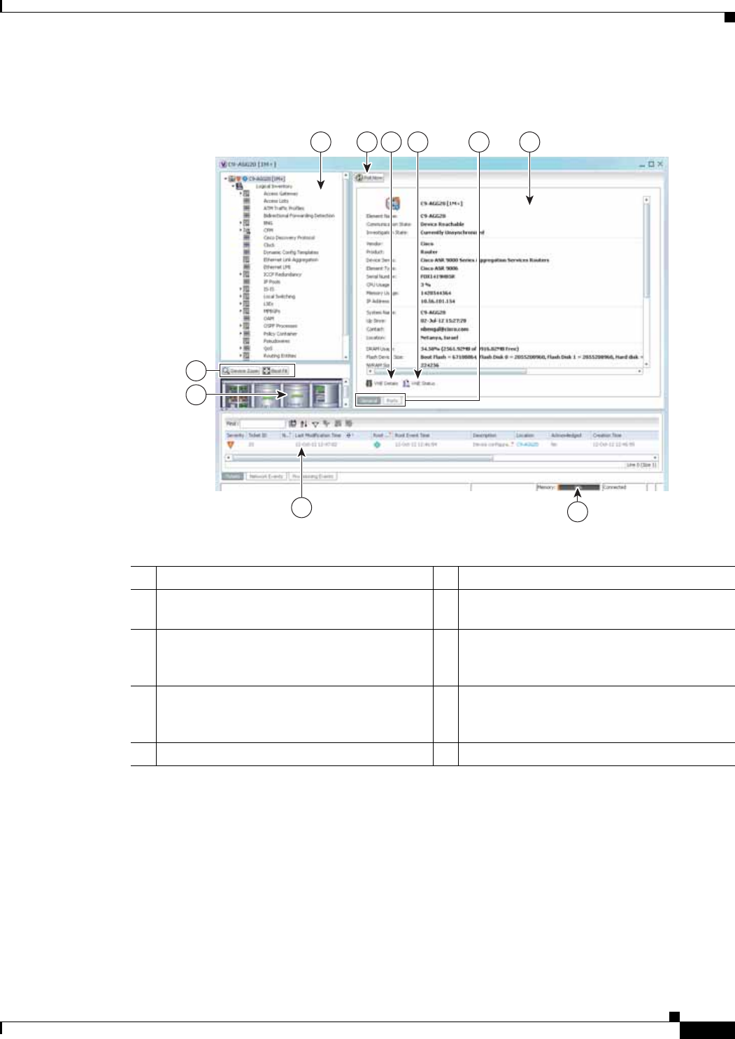
3-11
Cisco Prime Network 4.0 User Guide
OL-29343-01
Chapter 3 Viewing and Managing NE Properties Inventory Window
Figure 3-2 Inventory Window
The inventory window displays the physical and logical inventory for the selected item. For more
information about the options in the inventory window, see:
• Navigation Pane, page 3-12
• Device View Pane, page 3-13
• Device View Pane Toolbar, page 3-14
• Ticket and Events Pane, page 3-15
• Content Pane, page 3-13
1Navigation pane 6Content pane
2Poll Now button (see Performing a Manual
Device Poll, page 3-18)7Status bar
3VNE Details button (see VNE Properties
Window (VNE Status Button in the content
pane of the Inventory Window), page 3-16)
8Ticket and events pane
4VNE Status button (see VNE Communication
Status (VNE Details Button in the content
pane of the Inventory Window), page 3-17)
9Device view pane
5Content pane tabs 10 Device view pane toolbar
320084
8
1 2 634
7
9
10
5

3-12
Cisco Prime Network 4.0 User Guide OL-29343-01
Chapter 3 Viewing and Managing NE Properties
Inventory Window
• Checking VNE Connectivity and Communication Status, page 3-16
• Working with Ports, page 3-23
All areas displayed in the inventory window are correlated; this means that selecting an option in one
area affects the information displayed in the other areas.
The information displayed in the inventory window varies according to the item selected in the
navigation pane.
To view logical inventory information, expand the Logical Inventory branch. For more information about
logical inventory information, see Viewing the Logical Properties of a Network Element, page 3-27.
To view physical inventory information, expand the Physical Inventory branch. For more information
about physical inventory information, see Viewing the Physical Properties of a Device, page 3-19.
Click Poll Now to update the display with the current VNE information.
Click the top right corner to close the inventory window.
Navigation Pane
The navigation pane in the inventory window displays a tree-and-branch representation of the selected
device and its modules. The navigation pane contains two main branches:
• Logical Inventory—Includes logical items related to the selected element, such as access lists, ATM
traffic profiles, and routing entities.
• Physical Inventory—Includes the various device components, such as chassis, satellite, cards,
subslots, and so on.
When you select an item in the navigation pane, the information displayed in the content pane is updated.
You can expand and collapse the branches in the navigation pane to display and hide information as
needed.
The window heading and the highest level in the navigation pane display the name of the VNE given to
the element as defined in Cisco Prime Network Administration. The element icon and status are
displayed at the top of the navigation and content panes.
The color of the element icon reflects the element operational status. For more information about
indicators of operational health and status, see:
• Prime Network Vision Status Indicators, page 2-17
• VNE Management States, page 2-19
Status Indicators
A status indicator icon appears next to the element icon for any unacknowledged tickets associated with
the element. In addition, status indicator icons are displayed next to the specific logical or physical
inventory branches that are associated with the ticket.
If you click a branch in the navigation pane that contains a status icon, the associated tickets and events
are displayed in the tickets and events pane at the bottom of the inventory window.

3-13
Cisco Prime Network 4.0 User Guide
OL-29343-01
Chapter 3 Viewing and Managing NE Properties Inventory Window
Communication and Investigation State Icons
The navigation pane can also display a communication or investigation state icon next to the element
icon in the navigation and content panes.
For more information about communication and investigation state icons, see VNE Management States,
page 2-19.
Content Pane
The content pane contains two tabs:
• General—Contains physical or logical information specific to the item you select in the navigation
pane or device view panel; for example, information about pseudowires or the chassis.
The General tab can also display context-sensitive tabs and buttons; the buttons displayed depend
on your selection in the navigation pane or device view panel. For example, if an ATM port is
selected, the Show VC Table, Show Cross-Connect, or Show Encapsulation button might be
displayed.
• Ports—Lists all ports on the device with their current alarm status, location, and other properties,
and enables you to change their status by using a right-click menu. For more information, see
Working with Ports, page 3-23.
The content pane can also display context-sensitive tabs and buttons; the buttons displayed depend on
your selection in the navigation pane or device view panel. For example, if an ATM port is selected, the
Show VC Table, Show Cross-Connect, or Show Encapsulation button might be displayed.
In addition, you can view the properties of a row in a table by double-clicking the row or by
right-clicking the row and choosing Properties.
For information about tables that appear in the content pane, see Filtering and Sorting Tabular Content,
page 2-42.
Device View Pane
The device view pane enables you to visually locate elements in the chassis and identify their status. All
occupied slots in the chassis are rendered in the device view pane. If a port is down, it is shown in red
in both the navigation pane and the device view pane, allowing you to quickly pinpoint the problem.
Figure 3-3 provides an example of the device view pane for a Cisco device. The circled slot in the device
view pane corresponds to the circled slot in the physical inventory navigation pane. If you click a port
in the device view pane (see the circled port), Prime Network Vision displays both the properties of the
element and its location in the navigation pane and content pane.
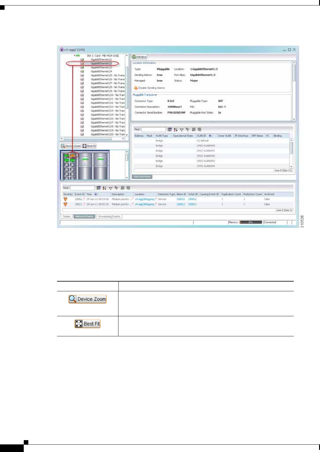
3-14
Cisco Prime Network 4.0 User Guide OL-29343-01
Chapter 3 Viewing and Managing NE Properties
Inventory Window
Figure 3-3 Device View Pane
Device View Pane Toolbar
The following tools for working with the device view pane:
Icon Description
Displays an enhanced view of the components within the device in
a browse box as you move over the device view panel with the
selection tool.
Fits the entire view of the element in the device view panel.

3-15
Cisco Prime Network 4.0 User Guide
OL-29343-01
Chapter 3 Viewing and Managing NE Properties Inventory Window
Ticket and Events Pane
The ticket and events pane is displayed at the bottom of the inventory window and contains the following
tabs:
• Tickets—Displays the tickets that are collected on the selected element, service, or component in
the navigation pane.
Table 9-3 on page 9-5 describes the information that is available in the Tickets tab.
• Network Events—Displays all active network events associated with tickets and alarms, and all
archived events with a timestamp that falls within the specified events history size (see Adjusting
the Prime Network Vision GUI Client Settings, page 2-40).
Table 3-7 describes the information that is available in the Network Events tab.
• Provisioning Events—Available to users with the Configurator role or higher for the selected
element. This tab displays provisioning events with their source in the selected element and with a
timestamp that falls within the specified events history size (see Adjusting the Prime Network
Vision GUI Client Settings, page 2-40).
All activations that occur are also included in this tab.
Table 8-4 on page 8-5 describes the information that is available in the Provisioning Events tab.
Note Provisioning events that are caused by workflows (AVM 66) are not displayed in this table
even if the element is affected by the workflow.
Table 3-7 Network Events Tab in Logical Inventory
Field Description
Severity Icon indicating the severity of the alarm on the event
Event ID Event identifier, assigned sequentially.
Time Date and time when the event occurred and was logged and
recorded.
Description Description of the event.
Location Entity that triggered the event.
Detection Type Method by which the event was detected, such as Service or Syslog.
Alarm ID Identifier of the alarm associated with the event.
Ticket ID Identifier of the ticket associated with the event.
Causing Event ID Identifier of the causing event.
Duplication Count For network events, the duplication count is calculated by the VNE
and pertains only to flapping events. The duplication count
represents the number of noncleared events aggregated by the
flapping event.
Reduction Count For network events, the reduction count is calculated by the VNE
and pertains only to flapping events. The reduction count represents
the number of events that are aggregated by the flapping event.
Archived Whether the event is archived: True or False.

3-16
Cisco Prime Network 4.0 User Guide OL-29343-01
Chapter 3 Viewing and Managing NE Properties
Checking VNE Connectivity and Communication Status
When displaying network and provisioning events, Prime Network Vision monitors the history size value
defined in the Events tab of the Options dialog box (Tools > Options > Events). The default value is six
hours and can be changed in Prime Network Administration. In addition, Prime Network Vision limits
the maximum number of network and provisioning events that are sent from the server to client to 15,000
each. If the number of network or provisioning events exceeds the limit specified in the Options Events
tab or the 15,000 maximum limit, Prime Network Vision purges the oldest events from table. The
purging mechanism runs once per minute.
Tip You can display or hide the ticket and events pane by clicking the arrows displayed below the device
view panel.
Checking VNE Connectivity and Communication Status
Virtual Network Elements (VNEs) are the Prime Network entities that simulate managed devices. Each
VNE is assigned to manage a single network element instance and is designated by the NE name and
IP address.
VNEs are created using the Prime Network Administration GUI client. After a VNE is created and
started, Prime Network investigates the network element and automatically builds a live model of it
including its physical and logical inventory, configuration, and status. As different VNEs build their
model, a complete model of the network is created.
For the most part, VNE operations are hidden from Prime Network Vision GUI client users because those
users are interested in devices, not these back-end processes. But VNEs must have connectivity to a
device in order to maintain the NE model. To provide connectivity and polling information, you can view
VNE properties from the device inventory:
• VNE Status to view the VNE Properties window. This window provides details such as the VNE’s
protocol and polling settings and other configuration information. See VNE Properties Window
(VNE Status Button in the content pane of the Inventory Window), page 3-16.
• VNE Details to view more details about device and VNE connectivity. See VNE Communication
Status (VNE Details Button in the content pane of the Inventory Window), page 3-17.
VNE Properties Window (VNE Status Button in the content pane of the Inventory Window)
Figure 3-4 provides an example of a VNE properties window. This VNE is modeling a Cisco 3620 router.

3-17
Cisco Prime Network 4.0 User Guide
OL-29343-01
Chapter 3 Viewing and Managing NE Properties Checking VNE Connectivity and Communication Status
Figure 3-4 VNE Properties Window
Note VNE status is not the same as device status. A device may be fully reachable and operating even though
the VNE status is Down, Unreachable, or Disconnected.
The Cisco Prime Network 4.0 Administrator Guide describes these properties in detail, but for a Prime
Network Vision GUI Client user, probably the most important information is the VNE status.
VNE Communication Status (VNE Details Button in the content pane of the Inventory Window)
Figure 3-5 provides an example of a VNE Status Details window for a different VNE. This window
provides information about the VNE and device connectivity.
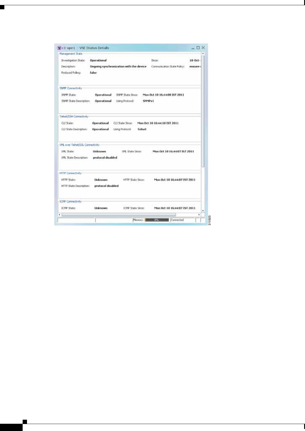
3-18
Cisco Prime Network 4.0 User Guide OL-29343-01
Chapter 3 Viewing and Managing NE Properties
Checking VNE Connectivity and Communication Status
Figure 3-5 VNE Status Details Window
The VNE Status Details window provides this information about the VNE:
• Its management connectivity state, which has to do with how the VNE was configured
• The protocols the VNE is using to communicate with the device and the status of each
• Whether the device is generating syslogs or traps
In the Management State area, if the Reduced Polling field is true and the Investigation State is Currently
Unsychronized, refer to the information in the topic Performing a Manual Device Poll, page 3-18.
This information can be useful to users who are troubleshooting device problems. For more information
about the VNE Status Details window, see the Cisco Prime Network 4.0 Administrator Guide.
Performing a Manual Device Poll
The VNE settings determine how often a VNE polls a device to update its model. Some VNEs use the
reduced polling (also called event-based polling) mechanism. A reduced polling VNE polls the device
when a configuration change syslog is received and immediately updates the VNE information
accordingly. In other words, updates are driven by incoming events.
The risk with reduced polling is dropped events. But if an event is dropped, the network element shows
a Currently Unsynchronized investigation state. If you notice this VNE state, initiate polling by
right-clicking the element and choosing VNE Tools > Poll Now.
For more information about reduced polling, see the Cisco Prime Network 4.0 Administrator Guide.

3-19
Cisco Prime Network 4.0 User Guide
OL-29343-01
Chapter 3 Viewing and Managing NE Properties Viewing the Physical Properties of a Device
Viewing the Physical Properties of a Device
Each device that is managed by Prime Network is modeled in the same manner. The physical inventory
reflects the physical components of the managed network element, as shown in Table 3-8.
Physical inventory is continuously updated for both status and configuration. The addition of a new card,
the removal of a card, or any change to the device is reflected by the VNE and updated instantly.
If you physically remove an item that Prime Network Vision is managing, the following changes occur
in physical inventory, depending on the item removed:
• Removing an item other than a pluggable transceiver results in the following changes:
–
The color of the icon in physical inventory changes to black.
–
The item’s status changes to Out.
The other properties of the removed item reflect the most recent value that was updated from the
device with the following exceptions:
–
Cards—If the card was participating in a card redundancy configuration, the redundancy state
changes to None.
–
Port—The operational status of the port changes to Down.
• Removing a pluggable transceiver results in the following changes:
–
The color of the pluggable transceiver icon changes to gray.
–
The pluggable transceiver status changes to Disabled.
–
In the Pluggable Transceiver panel:
— The properties are no longer displayed.
— The connector type changes to Unknown.
— The pluggable port state changes to Out.
Table 3-8 Physical Inventory Icons
Icon Device
Chassis
Satellite
Shelf
Card/Subcard
Port/Logical Port
Pluggable Transceiver
Unmanaged Port
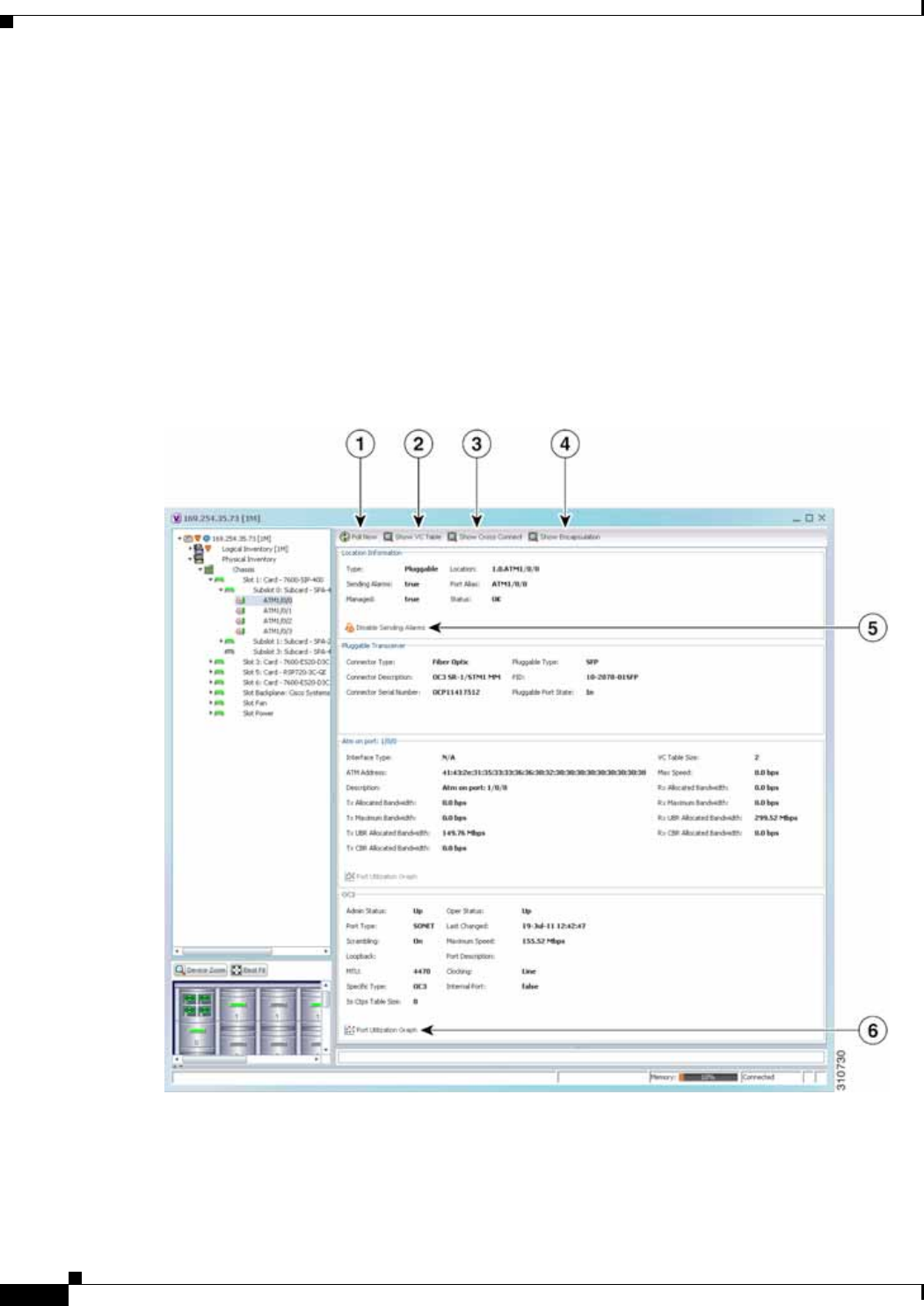
3-20
Cisco Prime Network 4.0 User Guide OL-29343-01
Chapter 3 Viewing and Managing NE Properties
Viewing the Physical Properties of a Device
Fans and power supplies are displayed in physical inventory if they are field replacable units (FRUs).
The manner in which the fans are displayed depends on whether the fans can be separated or not:
• If the fans under the fan trays are inseparable, only the fan trays are represented.
• If the fans under the fan trays can be separated, they are shown as separate items in physical
inventory.
The window displayed for all the devices is similar in appearance. However, the individual sections that
are displayed depends on the selected item. For example, when a port that supports pluggable
transceivers is selected, the Pluggable Transceiver section is displayed. This section provides
information such as the port connector’s type and serial number, as well as an indication whether a
transceiver is currently plugged in.
Figure 3-6 shows an example of a selection in physical inventory and the available buttons.
Figure 3-6 Physical Inventory Example

3-21
Cisco Prime Network 4.0 User Guide
OL-29343-01
Chapter 3 Viewing and Managing NE Properties Viewing the Physical Properties of a Device
The buttons that are displayed in the physical inventory content pane depend on the selected port. For
information about configuring topology from a port, see Adding Static Links, page 6-15. For a detailed
description of device properties, see Viewing the Properties of a Network Element, page 3-6.
Redundancy Support
In Prime Network, redundancy is modeled as part of the physical inventory. You can view the redundancy
parameters including the following:
• Redundancy Configured—Indicates whether redundancy is configured for the Route Switch
Processor (RSP) or Route Processor (RP) card. This parameter displays “Working” if redundancy is
configured and “None” if it is not configured.
• Redundancy Status—Indicates the redundancy status of the RSP or RP card, which can be Active or
Standby Mode.
• Redundancy Type—The type of redundancy, which can be Stateful or Stateless. This parameter is
available only for Cisco ASR9000 and Cisco ASR903 series routers.
• Redundancy Info—Provides information about the redundancy technology that is configured. For
example, Nonstop Routing (NSR), Stateful Switchover (SSO), or Route Processor Redundancy
(RPR). This parameter is available only for Cisco ASR9000 and Cisco ASR903 series routers.
Note If SSO is configured, then the Redundancy type will be Stateful. If RPR is configured, then the
Redundancy Type will be Stateless.
1Poll Now button Poll the VNE and update the information as needed.
For more information, see Performing a Manual Device Poll, page 3-18.
2Show VC Table button Displays virtual circuit (VC) information for the selected port.
For more information, see Viewing ATM VPI and VCI Properties,
page 20-10.
3Show Cross Connect
button Displays cross-connect information for incoming and outgoing ports.
For more information, see Viewing ATM Virtual Connection
Cross-Connects, page 20-6.
4Show Encapsulation
button Displays encapsulation information for incoming and outgoing traffic for
the selected item.
For more information, see Viewing Encapsulation Information,
page 20-11.
5Disable Sending
Alarms button Enables you to manage the alarms on a port.
For more information, see Working with Ports, page 3-23.
6Port Utilization Graph
button Displays the selected port traffic statistics: Rx/Tx Rate and Rx/Tx Rate
History.
For more information, see Generating a Port Utilization Graph,
page 3-27.
—Show DLCI Table
button (not displayed) Displays data-link connection identifier (DCLI) information for the
selected port.
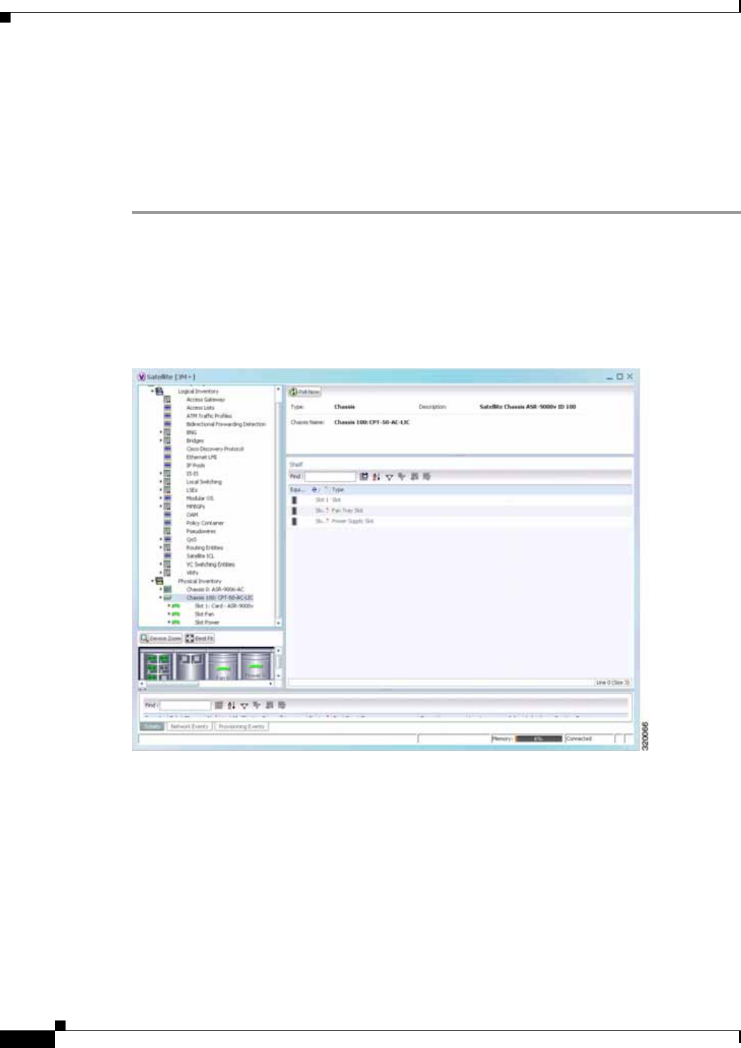
3-22
Cisco Prime Network 4.0 User Guide OL-29343-01
Chapter 3 Viewing and Managing NE Properties
Viewing the Physical Properties of a Device
Viewing Satellite Properties
Prime Network provides satellite support for Cisco Aggregation Service Router (ASR) 9000 series
network elements. Satellites are used to enhance performance bandwidth of Cisco ASR 9000 network
elements. Each satellite is modeled as a chassis in the physical inventory.
To view the satellite properties:
Step 1 In Cisco Prime Network Vision, double-click the required device.
Step 2 In the Inventory window, choose Physical Inventory > Satellite. Satellite is modeled as a type of chassis
in the physical inventory.
Figure 3-7 shows an example of the information (including the slots) displayed when a satellite is
selected in the physical inventory branch of the inventory window.
Figure 3-7 Satellite Properties

3-23
Cisco Prime Network 4.0 User Guide
OL-29343-01
Chapter 3 Viewing and Managing NE Properties Working with Ports
One or more satellites are connected to the host Cisco ASR 9000 series network element by using the
physical ethernet links, which also act as inter-chassis links (ICLs) for connecting the satellites with the
other chassis or satellites within the host.
To view the satellite ICLs, choose the Satellite ICL container in the logical inventory of the device. The
content pane displays a list of satellite ICLs with the following details.
Working with Ports
The following topics describe some of the options available for working with ports:
• Viewing Port Status and Properties, page 3-23
• Viewing a Port Configuration, page 3-25
• Disabling and Enabling Alarms, page 3-26
• Generating a Port Utilization Graph, page 3-27
You can also perform port configuration tasks such as managing port descriptions, changing port status,
assigning ports to VLANs, and so forth using basic commands that are launched from right-click
contextual menus. The commands are described in Setting Up Devices and Validating Device
Information, page 1-4.
Viewing Port Status and Properties
Prime Network Vision displays all ports on a device in the Ports tab in the inventory window.
This information is available to users with an Operator or higher role on the selected device. Users with
a Configurator or higher role can modify the status of a single port or a selected group of ports as
described in the following sections:
• Disabling and Enabling Alarms, page 3-26
• Generating a Port Utilization Graph, page 3-27
You can export the port list from Prime Network Vision by using the Export to CSV option in the toolbar.
Table 3-9 Satellite ICL Properties
Field Description
Host Interface Interface by which satellite is configured on the host network element. Click
the hyperlink to view the interface properties in the physical inventory.
Satellite IC Interface Inter-chassis interface used by the satellite. Click the hyperlink to view the
satellite interface properties in the physical inventory.
Satellite ID Satellite ID. Click the hyperlink to view the satellite properties in the physical
inventory.
Satellite Port Range Port associated with the satellite.
Satellite Status Connection status of the satellite: Connected or Disconnected.
Fabric Link Status Status of the fabric link connected to the satellite.
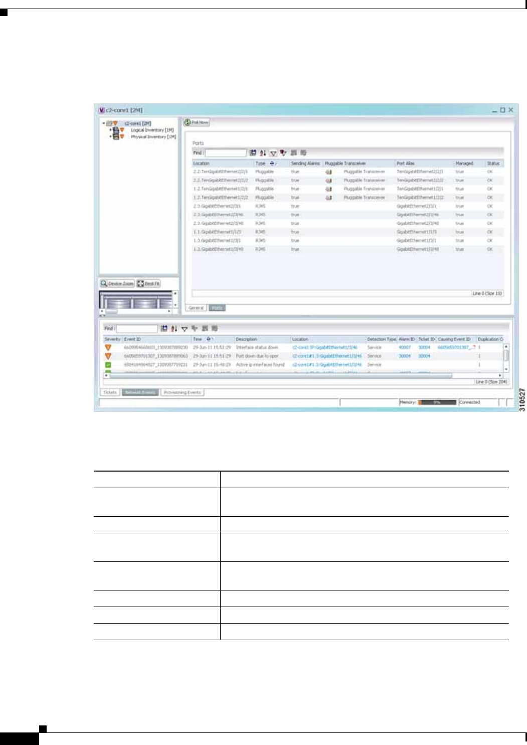
3-24
Cisco Prime Network 4.0 User Guide OL-29343-01
Chapter 3 Viewing and Managing NE Properties
Working with Ports
Figure 3-8 shows an example of the Ports tab in the inventory window.
Figure 3-8 Ports Tab in the Inventory Window
Table 3-10 describes the information that is displayed in the Ports tab.
Table 3-10 Ports Tab in the Inventory Window
Field Description
Location Location of the port in the device, using the format
slot.module/port, such as 1.GigabitEthernet1/14.
Type Port type, such as RJ45 or Pluggable.
Sending Alarms Whether or not the port is configured for sending alarms: True or
False.
Pluggable Transceiver For the Pluggable port type, indicates that the port can hold a
pluggable transceiver.
Port Alias Name used in the device CLI or EMS for the port.
Managed Whether or not the port is managed: True or False.
Status Port status, such as OK, Major, or Disabled.
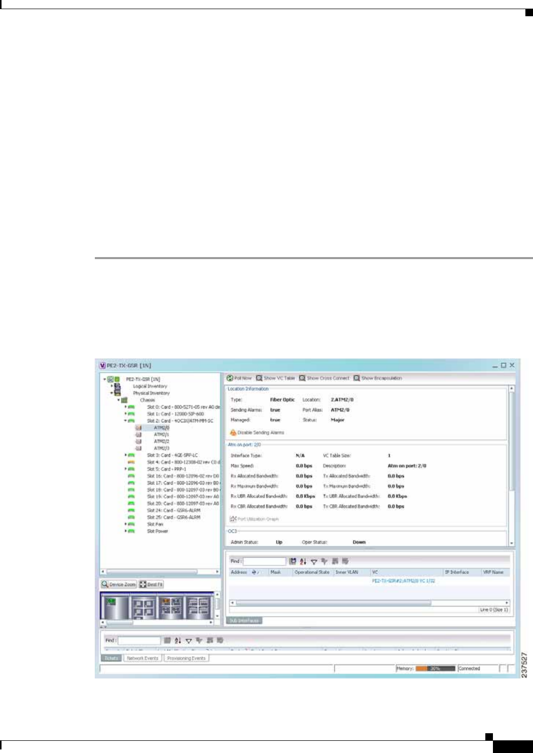
3-25
Cisco Prime Network 4.0 User Guide
OL-29343-01
Chapter 3 Viewing and Managing NE Properties Working with Ports
Viewing a Port Configuration
In addition to viewing logical inventory information from the logical inventory branch, you can view
services provisioned on physical ports by clicking a physical port in the physical inventory branch.
Information that is displayed includes:
• Physical layer information.
• Layer 2 information, such as ATM and Ethernet.
• Subinterfaces used by a VRF.
You can also perform port configuration tasks such as managing port descriptions, changing port status,
assigning ports to VLANs, and so forth using basic commands that are launched from right-click
contextual menus. The commands are described in Setting Up Devices and Validating Device
Information, page 1-4. That topic also describes commands for configuring interfaces.
To view a port’s configuration:
Step 1 In Cisco Prime Network Vision, double-click the required device.
Step 2 In the inventory window, choose Physical Inventory > Chassis > Slot > Subslot > Port.
Figure 3-9 shows an example of the information (including the subinterfaces) displayed when a port is
selected in the physical inventory branch of the inventory window.
Figure 3-9 Port Information in the Inventory Window

3-26
Cisco Prime Network 4.0 User Guide OL-29343-01
Chapter 3 Viewing and Managing NE Properties
Working with Ports
The subinterface is a logical interface defined in the device; all of its parameters can be part of its
configuration. Table 3-11 describes the information that can be displayed in the Subinterfaces table. Not
all fields appear in all Subinterfaces tables.
Disabling and Enabling Alarms
By default, alarms are enabled on all ports. When the alarms are disabled on a port, no alarms are
generated for the port and they are not displayed in the ticket and events pane.
To disable alarms on ports:
Step 1 Open the inventory window for the required device.
Step 2 To disable alarms on individual ports, right-click the port and choose Disable Sending Alarms.
The Sending Alarms field displays the value false, indicating that the alarm for the required port has been
disabled, and the content pane displays the Enable Sending Alarms button.
Table 3-11 Subinterfaces Table
Field Description
Address IP address defined in the subinterface.
Mask Subnet mask.
VLAN Type Type of VLAN, such as Bridge or IEEE 802.1Q.
Double-click the entry to view the Port IP VLAN Properties window
containing:
• VLAN type
• VLAN identifier
• Operational status
• A brief description of the VLAN
Operational State Operational state of the subinterface.
VLAN ID VLAN identifier.
Inner VLAN CE-VLAN identifier.
IP Interface IP interface, hyperlinked to the VRF properties in the inventory window.
VRF Name Name of the VRF.
Is MPLS Whether this is an MPLS interface: True or False.
VC Virtual connection (VC) configured on the interface, hyperlinked to the VC
Table window.
For more information about VC properties, see Viewing ATM Virtual
Connection Cross-Connects, page 20-6.
Tunnel Edge Hyperlinked entry to the specific tunnel edge in logical inventory.
Binding Hyperlinked entry to the specific bridge or pseudowire in logical inventory.

3-27
Cisco Prime Network 4.0 User Guide
OL-29343-01
Chapter 3 Viewing and Managing NE Properties Viewing the Logical Properties of a Network Element
Step 3 To disable alarms on one or more ports at the same time:
a. In the inventory window, click the Ports tab.
b. In the Ports table, select the required ports. You can select multiple ports by using the Ctrl and Shift
keys.
c. Right-click one of the selected ports, and choose Disable Sending Alarms. In response, the Sending
Alarms field displays the value false for the selected ports.
To enable alarms, use the previous procedure but choose Enable Sending Alarms.
Generating a Port Utilization Graph
Prime Network Vision enables you to view the Rx/Tx Rate and Rx/Tx Rate History of a port.
Note Port utilization graphs are for physical ports only. Port utilization graphs are not available for ATM,
E1/T1, or ATM IMA interfaces that are included in an IMA group.
To view port utilization statistics:
Step 1 Open the inventory window and select the required port in physical inventory.
Step 2 In the Ethernet CSMA/CD section, click Port Utilization Graph.
The following information is displayed in the Port Statistics dialog box:
• Rx Rate—The reception rate as a percentage.
• Rx Rate History—The reception rate history is displayed as a graph.
• Tx Rate—The transmission rate as a percentage.
• Tx Rate History—The transmission rate history is displayed as a graph.
Step 3 Click to close the Port Statistics dialog box.
Viewing the Logical Properties of a Network Element
Prime Network Vision enables you to view logical inventory information. Prime Network Vision
maintains logical inventory for each network element. The logical inventory reflects dynamic data such
as configuration data, forwarding, and service-related components that affect traffic handling in the
element.
The information displayed in the inventory window changes according to the type of element and branch
selected in the navigation pane.
You can also perform interface configuration tasks such as enabling and disabling interfaces, adding a
loopback interface, showing interface briefs, and so forth using basic commands that are launched from
right-click contextual menus. The commands are described in Setting Up Devices and Validating Device
Information, page 1-4. That topic also describes commands for configuring ports.
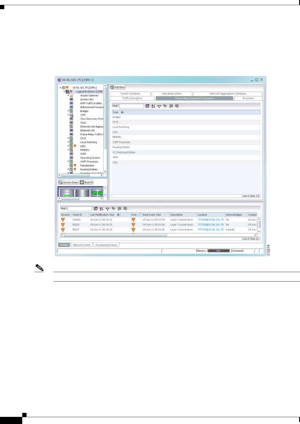
3-28
Cisco Prime Network 4.0 User Guide OL-29343-01
Chapter 3 Viewing and Managing NE Properties
Viewing the Logical Properties of a Network Element
Logical Inventory Window
Logical inventory information is displayed in the inventory window as shown in Figure 3-10.
Figure 3-10 Logical Inventory Information Displayed in the Inventory Window
Note For more information about opening the inventory window, see Inventory Window, page 3-9.

3-29
Cisco Prime Network 4.0 User Guide
OL-29343-01
Chapter 3 Viewing and Managing NE Properties Viewing the Logical Properties of a Network Element
Logical Inventory Navigation Pane Branches
Table 3-12 describes the branches that appear in the logical inventory navigation pane.
Table 3-12 Logical Inventory Navigation Pane Branches
This branch... Provides information about...
6rd IPv6 rapid development (6rd) tunnels
Access Gateway Multiple Spanning Tree (MST) and Resilient Ethernet Protocol
(REP) access gateways (AGs)
Access Lists Access lists
ATM Traffic Profiles Traffic profiles for ATM
Bidirectional Forwarding
Detection Bidirectional Forwarding Detection
BridgeILans Provider Backbone Bridge (PPB)
Bridges Configured VLANs
Carrier Grade NAT Carrier Grade Name Address Translation (NAT)
CFM Connectivity Fault Management (CFM)
Cisco Discovery Protocol Cisco Discovery Protocol (CDP)
Clock Network clock service, clock recovery, and Precision Time Protocol
(PTP) configuration
Context Name Context that is configured on devices that support multiple virtual
contexts
DTI Client DOCSIS Timing Interface (DTI) client that collects DTI server
master clock, DOCSIS timestamp, and Time of Day information
from the DTI Server
Ethernet Link Aggregation Ethernet aggregation groups
Ethernet LMI Ethernet Local Management Interface (LMI)
Fibre Node CMTS Configuration by Multiple Server Operator (MSO) or service
provider
Frame Relay Traffic Profiles Traffic profiles for Frame Relay
GRE Tunnels Generic routing encapsulation (GRE) tunneling protocol for IP
tunnels
ICCP Redundancy Inter-Chassis Communication Protocol (ICCP) redundancy groups
IMA Groups Inverse Multiplexing over ATM (IMA) groups
IP SLA Responder Cisco IOS Service Level Agreements (SLAs)
IS-IS Intermediate System-to-Intermediate System (IS-IS) protocol
Link Layer Discovery Protocol Link Layer Discovery Protocol (LLDP)
Local Switching Local switching
LSEs Local switching for MPLS interfaces
MAC Domain CMTS Mac Domain implementing DOCSIS function on
downstream and upstream paths

3-30
Cisco Prime Network 4.0 User Guide OL-29343-01
Chapter 3 Viewing and Managing NE Properties
Viewing the Logical Properties of a Network Element
Logical Inventory Navigation Pane Icons
Each branch in the logical inventory navigation pane is represented by an icon and, if appropriate,
includes an icon indicating the status.
Table A-3, “Logical Inventory Icons” describes the icons used in the logical inventory navigation pane.
MLPPP Multilink Point-to-Point (MLPPP) configurations
Modular OS Modular operating systems for Cisco IOX XR devices
MPBGPs Properties associated with provider edge (PE) network elements.
The Multiprotocol Border Gateway Protocols (MP-BGPs) inventory
folder contains information such as BGP identifier, local and remote
Autonomous System (AS), VRF name, cross-VRF routing, and so
on.
MPLS-TP MPLS Transport Profile (MPLS-TP).
Narrowband Channels DOCSIS 1.x/2.0 protocol downstream channel that contians one RF
channel
OAM Link operations, administration, and maintenance (OAM).
Operating System Operating systems for Cisco IOS devices.
OSPF Processes OSPF processes, such as the Shortest Path First (SPF) timer
settings, OSPF neighbors, and OSPF interfaces.
Pseudowires Pseudowire end-to-end emulation (PW3E) tunnels.
Resilient Ethernet Protocol Resilient Ethernet Protocol (REP).
Routing Entities Routing table entries and IP interfaces.
Session Border Controller Session Border Controller (SBC) configuration.
Spanning Tree Protocol Spanning Tree Protocol (STP) and Multiple Spanning Tree Protocol
(MSTP) configurations.
Traffic Engineering Tunnels Traffic engineering (TE) tunnels.
Tunnel Traffic Descriptors Tunnel traffic descriptors associated with the element.
VC Switching Entities Cross-connects and VC traffic.
VRFs Virtual Routing and Forwarding (VRF).
VSIs Virtual Switch Interface (VSI) instance names, associated
pseudowire information, virtual circuit IDs, and so on.
VTP VLAN Trunk Protocol (VTP) domain names, modes, version
numbers, and so on.
Wideband Channels Physical RF channels over which MPEG-TS packets are carried
Table 3-12 Logical Inventory Navigation Pane Branches (continued)
This branch... Provides information about...

3-31
Cisco Prime Network 4.0 User Guide
OL-29343-01
Chapter 3 Viewing and Managing NE Properties Viewing Device Operating System Information
Logical Inventory Content Pane Tabs
Table 3-13 describes the tabs that are displayed in the logical inventory content pane when you select
Logical Inventory, depending on the device configuration.
Note Prime Network Vision does not display the tabs in Table 3-13 for devices that support multiple contexts.
Instead, when you select Logical Inventory for a device that contains multiple contexts, Prime Network
Vision displays a Contexts table that lists the contexts configured on the device.
Viewing Device Operating System Information
Prime Network Vision discovers and automatically displays operating system information for
Cisco IOS, Cisco IOS XR, and Cisco IOS XE devices in logical inventory. For other devices, choose the
element name at the top of the inventory window navigation pane.
Table 3-13 Logical Inventory Content Pane Tabs
Tab Description
Data Link Aggregation
Containers Lists the data link aggregations configured on the selected entity,
such as Ethernet link aggregations.
Encapsulation Aggregation
Containers Lists the encapsulation aggregations configured on the selected
entity.
Forwarding Component
Containers Lists the context profiles for which logical inventory information
can be displayed, such as routing entities and bridges.
Operating System Provides information about the operating system on the selected
entity.
Physical Layer Aggregation
Containers Lists aggregations configured at the physical layer for the selected
entity, such as IMA groups.
Processes Lists the processes running on the selected entity, such as Clock or
CDP.
Traffic Descriptors Lists the profiles for which logical inventory information can be
displayed, such as Frame Relay traffic profiles and Address
Resolution Protocol (ARP) entities.
Tunnel Containers Lists the types of tunnels that are configured on the selected entity,
such as pseudowires or GRE tunnels.

3-32
Cisco Prime Network 4.0 User Guide OL-29343-01
Chapter 3 Viewing and Managing NE Properties
Viewing Device Operating System Information
To view operating system information for Cisco IOS, Cisco IOS XR, or Cisco IOS XE devices:
Step 1 In Prime Network Vision, double-click the required device.
Step 2 For a Cisco IOS device, view information about the operating system by clicking Logical Inventory and
choose the Operating System tab. Table 3-14 describes the information that is displayed in the
Operating System tab.
Step 3 For a Cisco IOS XR device, view information about the operating system by opening the inventory
window and choosing Logical Inventory > Modular OS. Figure 3-11 shows an example of the
information that is displayed for Cisco IOS XR devices.
Table 3-14 Operating System Information in Logical Inventory
Field Description
Is K9Sec Whether or not the K9 security feature is enabled on the operating
system: True or False
Family Cisco family, based on the device platform, such as CRS_IOS or
C12K_IOS_XR.
SDR Mac Addr Secure Domain Router (SDR) MAC address.
This field applies to Cisco IOS XR devices only.
Software Version Cisco IOS software version, such as 12.2(33)SRC3, Release Software
(fc2).
Boot Software Cisco IOS system image information.
ROM Version Cisco IOS bootstrap software version, such as 12.2(17r)SX3.
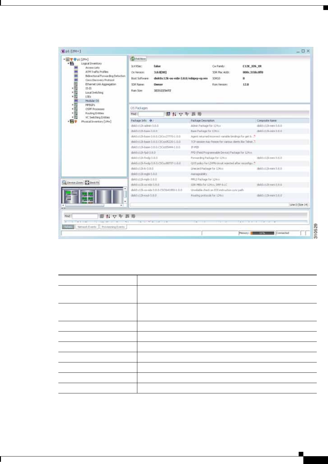
3-33
Cisco Prime Network 4.0 User Guide
OL-29343-01
Chapter 3 Viewing and Managing NE Properties Viewing Device Operating System Information
Figure 3-11 Modular OS Information in Logical Inventory
Table 3-15 describes the information that is displayed for Cisco IOS XR system.
Table 3-15 Modular OS Information in Logical Inventory
Field Description
Is K9Sec Whether or not the K9 security feature is enabled on the operating
system: True or False
Cw Family Cisco family, based on the device platform, such as CRS_IOS_XR
or C12K_IOS_XR.
SDR Mac Addr Secure Domain Router (SDR) MAC address.
OS Version Cisco IOS XR software version, such as 3.8.0[00].
Boot Software Cisco IOS XR system image information.
SDR Name SDR name.
SDR Id SDR identifier.
ROM Version Cisco IOS XR bootstrap software version, such as 1.51.
RAM Size Size, in kilobytes, of the device processor RAM.

3-34
Cisco Prime Network 4.0 User Guide OL-29343-01
Chapter 3 Viewing and Managing NE Properties
Running an Activation from the Activation Menu
Table 3-16 describes the information that is displayed for modular operating systems in the
Operating System tab.
Running an Activation from the Activation Menu
Note Transaction Manager replaces the Prime Network Workflow and Action features in all new installations
of Prime Network 4.0. If you have upgraded to Prime Network 4.0, the Workflow and Activation features
are still available, but they will be deprecated in the future. We recommend that you use Transaction
Manager. Transaction Manager is described in the Cisco Prime Network 4.0 Customization Guide.
You can run activation wizards from the GUI client using the Activations main menu. These are wizards
that have been created using the Activation Wizard Builder (AWB), which is described in the
Cisco Prime Network 4.0 Customization Guide. You can only run activations on devices that are within
your device scope.
OS Packages Table
Package Info Information on the individual package and its version, such as
disk0:hfr-admin-3.9.3.14
Package Description Description of the package, such as FPD (Field Programmable
Device) Package.
Composite Name Composite package name of the package with the date and time,
such as:
Tues Feb 8 20:37:07.966 UTC
disk0:comp-hfr-mini-3.9.3.14
Table 3-15 Modular OS Information in Logical Inventory (continued)
Field Description
Table 3-16 Modular OS Information in Operating System Tab
Field Description
Is K9Sec Whether or not the K9 security feature is enabled on the operating
system: True or False
Family Cisco family, based on the device platform, such as CRS_IOS_XR or
C12K_IOS_XR.
Software Version Cisco IOS XR software version, such as 4.0.0[Default].
SDR Mac Addr Secure Domain Router (SDR) MAC address.
Boot Software Cisco IOS XR system image information.
SDR ID SDR identifier.
SDR Name SDR name.
ROM Version Cisco IOS XR bootstrap software version, such as 1.54.

3-35
Cisco Prime Network 4.0 User Guide
OL-29343-01
Chapter 3 Viewing and Managing NE Properties Running an Activation from the Activation Menu
These topics describe how to run activations:
• Network Activation Window, page 3-35
• Running Activations, page 3-35
• Searching for Activations (Activation History), page 3-36
• Rolling Back an Activation, page 3-36
• Cloning an Existing Activation, page 3-37
• Deleting Activations, page 3-37
Network Activation Window
Note Transaction Manager replaces the Prime Network Workflow and Activation features in all new
installations of Prime Network 4.0. If you have upgraded to Prime Network 4.0, the Workflow and
Activation features are still available, but they will deprecated in the future. We recommend that you use
Transaction Manager.
Operators can access Activation wizards by launching them from the Activation menu in Prime Network
Vision. The window is divided into the following parts.
Running Activations
Activations can be launched from the Prime Network Vision GUI client.
Note The Cisco Developer Network (CDN) has some scripts that you can use as examples for using the
framework. Other activation scripts are only available through Cisco Advanced Services.
Step 1 From the Vision main menu, choose Activation > Activation. This opens a menu that lists the
activations that the user can launch, depending on their user access role.
Step 2 Expand the tree and highlight the activation wizard you want to launch, and click Next.
Step 3 Enter all of the required data. You can only run activations on devices that are within your device scope.
Activation Menu Choices Description
Activation Displays available activation wizards. From here operators can launch the
wizards, enter the necessary information, and run the activation.
Activation History Displays all the activations that have been executed.
Activation Modification
Utility Used by activation planners to download and upload wizard files.
Tip A best practice is to use the AWB to upload and download wizard
files.

3-36
Cisco Prime Network 4.0 User Guide OL-29343-01
Chapter 3 Viewing and Managing NE Properties
Running an Activation from the Activation Menu
Step 4 Check your entries and preview your changes:
a. Click the User Input tab and check all of the values you entered.
b. Click the Preview Configuration tab, which displays and validates the CLI commands that will be
run on the device. It also highlights any errors so that you can make corrections to your input.
Step 5 Run the activation.
Note You might be prompted to enter your device access credentials. Once you have entered them,
these credentials will be used for every subsequent activation in the same GUI client session. If
you want to change the credentials, click Edit Credentials.
Step 6 View the output:
a. Select the activation in the Activation History window, right-click and choose Show Output. The
information presented in similar to the data displayed in Step 4 except it reflects the real runtime
results.
–
Workflow Output—The sequence of commands that were run on the devices.
–
CLI Output—The actual CLI commands that were executed for the selected activation (for
activations with an Add operation and a Done state).
b. If you want to view the output at a later time, export the activation to a local drive by clicking Export
to File. We recommend that you do not change the file type in case you seek help from a support
team.
Searching for Activations (Activation History)
The Activation History window displays information about executed activations, even if the activations
failed. The window displays a user-friendly search tools that allow you to locate specific activations and
filter the results. A counter displays the total number of activations in the system.
Keep the following in mind when using the Activation History window:
• Searches are case-insensitive and wild card characters are not supported.
• Results are returned only if the utility can match attributes with data in the database.
If the search results display any empty fields, this is most likely because the search criteria was not
entered correctly. If you confirm that the attributes were entered correctly and the fields are still empty,
the attributes were probably not used by the activation so they were not saved in the database.
Rolling Back an Activation
Completed activations can be deactivated—that is, rolled back—to return a device to its original
configuration. The rollback is a best effort; in some cases complete rollbacks may not be possible.
Before you roll back and activation, you can preview the CLI configuration sequence that will be
executed before the rollback is performed.

3-37
Cisco Prime Network 4.0 User Guide
OL-29343-01
Chapter 3 Viewing and Managing NE Properties Running an Activation from the Activation Menu
Step 1 From the Activation menu, choose Activation History. The Activation History window displays a list
of recent activation attempts.
Step 2 If necessary, search for the desired activation (see Searching for Activations (Activation History),
page 3-36).
Step 3 Select the activation and view its details. Activations can be rolled back if the Operation column displays
Add and the State column displays Done.
Note You can attempt a deactivation on an aborted activation to clean up partial rollbacks, but the
cleanup is a best effort.
Step 4 Right-click the selected activation and choose Deactivate Preview. You should verify the information
in the User Input tab and the Preview configuration tab (errors will be highlighted).
If you want to test the deactivation on a single device before performing it on all selected devices, export
the preview deactivation sequence to you local drive using Export to File. Then you can copy and paste
the commands to a specific device.
Step 5 Right-click the selected activation and choose Deactivate.
Step 6 On the confirmation dialog box, click Yes and Close.
Cloning an Existing Activation
Cloning is useful when you know you will have to repeat an activation in the future. The cloning process
saves all of the values that you entered in the original activation. This is useful when you have to perform
a deactivation, but you know it will be followed be a re-activation with the same settings.
Step 1 From the Activation menu, choose Activation.
Step 2 Select the activation that you want to clone and click Clone Activation. The Activation History window
is displayed.
Step 3 Search for the specific activation deployment that contains the settings you want to clone.
Note The search results return the search based on the activation you have selected.
Step 4 Click OK. The activation clone is created.
Deleting Activations
Users with Administrator privileges can delete activations and activation templates from the
Prime Network Administrator GUI client. Executed activations are automatically purged from the
Prime Network database according to the purging settings set by the administrator. For more information
on the Administrator GUI client, see the Cisco Prime Network 4.0 Administrator Guide.

3-38
Cisco Prime Network 4.0 User Guide OL-29343-01
Chapter 3 Viewing and Managing NE Properties
Running an Activation from the Activation Menu

CHAPTER
4-1
Cisco Prime Network 4.0 User Guide
OL-29343-01
4
Device Configurations and Software Images
Cisco Prime Network Change and Configuration Management (CCM) provides tools for managing the
software images and device configuration files used by the devices in your network.
CCM is also the launch point for the following Prime Network features:
• Transaction Manager, which is used to manage and execute activations on groups of devices.
Information appears in the Transaction Manager tab only if transactions have been created outside
of Prime Network and then added to Prime Network, as described in the Cisco Prime Network 4.0
Customization Guide.
• Command Manager, which provides a repository of all commands available in the system. It can be
used to create new commands and command sequences, which can then be applied to groups of
devices. Command Manager is described in the Cisco Prime Network 4.0 Customization Guide. .
These topics provide an overview of the features that CCM provides, some initial setup tasks you must
perform, and how to work with the GUI:
• What is Change and Configuration Management?, page 4-1
• Set Up Change and Configuration Management, page 4-3
• Use the CCM Dashboard, page 4-10
• Device Configurations, page 4-12
• Software Images, page 4-26
• Configuration Audit, page 4-45
• Compliance Audit, page 4-50
• Global Settings and Administration, page 4-61
For information on the devices supported by CCM, see Cisco Prime Network 4.0 Supported Cisco VNEs.
What is Change and Configuration Management?
Cisco Prime Network Change and Configuration Management provides tools that allow you to manage
the software and device configuration changes that are made to devices in your network. Device
configuration management tools are provided by the Configuration Management (CM) function, and
software image management tools are provided by the Image Management function. Operations can be
performed on user-created groups of devices. For more information on user-defined device groups, see
Device Groups Setup Tasks, page 4-9.

4-2
Cisco Prime Network 4.0 User Guide OL-29343-01
Chapter 4 Device Configurations and Software Images
What is Change and Configuration Management?
Configuration Management
Configuration Management enables you to control and track changes that are made to a device
configuration. It uses a change management feature to detect ongoing changes to devices in two ways:
• When doing periodic archiving of device configurations. If CM detects a change in a configuration
file, it will get the new version of the file from the device and copy it to the archive.
• When a configuration change notification is received from a device. This is called event-triggered
archiving. You can configure CM to copy a new version of a configuration file to the archive
whenever a change is detected, or to queue the changes and then copy the files to the archive
according to a schedule.
By default, neither of these methods are enabled. You can configure them from the Configuration
Management Settings page (see Configuration Management Setup Tasks, page 4-5).
Change Logs provide information on the changes made to devices in the network, sorted by their time
stamp. The Configuration Management Settings page controls how long these logs are saved. CM saves
messages that can be used for debugging in
PRIME_NETWORK_HOME/XMP_Platform/logs/ConfigArchive.log.
Note All configuration management operations are performed only on devices with Communication State as
Reachable and Investigation State as Operational, Partially Discovered, or Currently Unsynchronized.
For a Cisco IOS device with SNMPv3 configuration, configuration management operations can be
performed only if the device is configured with write permission for CISCO-CONFIG-COPY-MIB MIB
group.
Compliance Audit (and Configuration Audit)
Compliance Audit ensures that existing device configurations comply to your deployment’s policies.
Using Compliance Audit, you can create policies that can contain multiple rules, and policies can be
grouped together to create a policy profile which can be run on a set of devices, called audit of devices.
There is no limit on the number of policies, profiles, rules, and conditions that you can create using
Compliance Audit. It can scale up to 35,000 devices.
When a device is detected to be not confirming to a determined policy, Compliance Manager calls it a
violation. Subsequently, if available, it also recommends a fix, as configured by the administrator. The
violation details are saved in DB Schema for your reference later.
Compliance Audit replaces Configuration Audit (although Configuration Audit is still available.)
Image Management
Image Management provides tools for performing rapid, reliable software upgrades and automate the
steps associated with upgrade planning and monitoring. This topic provides an overview of both features
and an introduction to the Change and Configuration Management dashboard. Cisco IOS and Cisco IOS
XR software images are stored in the Prime Network image repository, to which you can add new images
by importing them from Cisco.com, from existing devices, from a local file system, or from an external
image repository. Software images in the repository are stored in binary format. Before an image is
distributed, NEIM performs an upgrade analysis to ensure that the network element is compatible with
the image; after an image is distributed, the images are applied immediately. For Cisco IOS XR devices,
you can add individual packages, deactivate packages, test changes before committing them, commit
changes, and roll packages back to stored rollback points. The image repository is located in the Cisco
Prime database. NEIM saves messages that can be used for debugging in
PRIME_NETWORK_HOME/XMP_Platform/logs/NEIM.log.

4-3
Cisco Prime Network 4.0 User Guide
OL-29343-01
Chapter 4 Device Configurations and Software Images Set Up Change and Configuration Management
Note All image management operations are performed only on completely managed devices. (This means the
Communication State of the device must be Reachable and Investigation State of the device must be
Operational.)
Note We recommend that you verify that an image operation is correct on a single device, preferably in a lab,
prior to distributing and activating a change in image on multiple devices in a production network.
Set Up Change and Configuration Management
The following topics explain the setup tasks required for Change and Configuration Management:
• Prime Network Setup Tasks, page 4-3
• Device Setup Tasks, page 4-4
• Configuration Management Setup Tasks, page 4-5
• NEIM Setup Tasks, page 4-7
• Device Groups Setup Tasks, page 4-9
Prime Network Setup Tasks
Verify the following:
• You can control user access in two ways:
–
By requiring users to enter device credentials before they can execute a CCM operation
–
By allowing users to run CCM jobs only if they have been granted those privileges (controlled
in their user account)
For information on enabling these features, see the information on global user settings in the Cisco
Prime Network 4.0 Administration Guide.
• Verify that CCM is installed. The installation process is described in the Cisco Prime Network 4.0
Installation Guide. CCM can be installed using the network-conf command. The guide includes
information about supported browsers, ports that must be available, and so forth.
To check if CCM is installed, log into the Prime Network gateway and enter the following command:
# cd $PRIME_NETWORK_HOME/Main
# dmctl status
If you see the following in the output, CCM is installed and running.
- Checking Prime Network Web Server Status [UP]
• Verify the port to be used. 8043 is the secure HTTP port enabled by default for Change and
Configuration Management web client. However, you can still use port 8080 to launch the Change
and Configuration Management GUI. To do so, you must manually enable it using this command:
# cd $NCCM_HOME/scripts/
# ./nccmHTTP.csh enable
# dmctl stop
# dmctl start

4-4
Cisco Prime Network 4.0 User Guide OL-29343-01
Chapter 4 Device Configurations and Software Images
Set Up Change and Configuration Management
To disable port 8080, perform the same operation but use the disable argument.
• The SCP port being used by a device must match the SCP port configured in the device VNE (the
VNE is Prime Network's model of the device). If a device is not using the default SCP port, be sure
that the VNE is also configured with the correct port. You can change the VNE's SCP port from the
Administration GUI client by editing the VNE properties (the Telnet/SSH tab). See the description
of VNE properties in the Cisco Prime Network 4.0 Administration Guide.
• If a gateway is behind a firewall, you must open special ports. You do not have to open special ports
if units are located behind firewalls (and with NAT). This approach prevents issues when the unit is
behind NAT, as the unit does not require a publicly available IP address for the gateway to contact it.
• SNMP read-write community in Cisco Prime Network Administration must match that on the
devices. Make sure that pop-up windows are enabled on the Firefox and Internet Explorer browsers.
• For IPv6, CM and NEIM functions run smoothly on a combination of network and devices with IPv6
addresses. Either the device or the unit must be configured with an IPv6 address to work. For
Cisco IOS devices with IPv6 address, the CM and NEIM operations will work only in FTP mode.
• For NEIM, verify that the gateway has sufficient space for the storing and staging directories (see
Change Image Management Global Settings, page 4-66).
• For config and image transfers using TFTP, verify that the TFTP directory is set up and available in
the Prime Network gateway and/or unit. To modify and verify the TFTP directory, run the following
commands:
–
To change the TFTP directory, go to the Prime Network directory and run the following
commands in the Prime Network gateway:
./runRegTool.sh -gs 127.0.0.1 set <GW/Unit IP> avm83/services/tftp/read-dir
tftp
dir name
./runRegTool.sh -gs 127.0.0.1 set <GW/Unit IP> avm83/services/tftp/write-dir
tftp
dir name
–
To check the TFTP directory, run the following commands:
./runRegTool.sh -gs 127.0.0.1 get <GW/Unit IP> avm83/services/tftp/read-dir
./runRegTool.sh -gs 127.0.0.1 get <GW/Unit IP> avm83/services/tftp/write-dir
–
Restart AVM 83 in the gateway or the unit, by using the following command:
anactl -avm 83 restart
Device Setup Tasks
• Verify that the device is supported. See Cisco Prime Network 4.0 Supported Cisco VNEs..
• For CM, verify that devices are configured to forward configuration change notifications to
Prime Network. This is documented as a prerequisite to adding VNEs, in the Cisco Prime Network
4.0 Administrator Guide. (Specifically, if you will be using event-triggered archiving, make sure the
logging gateway-IP command is configured on all devices. This command should have been
configured as a prerequisite to adding VNEs to Prime Network.)
• Simple Network Management Protocol (SNMP) read-write community must be configured on
devices. For more information on configuring SNMP community strings for devices, see the
Cisco Prime Network 4.0 Administrator Guide. SNMP read-write community in Cisco Prime
Network Administration must match that on the devices.

4-5
Cisco Prime Network 4.0 User Guide
OL-29343-01
Chapter 4 Device Configurations and Software Images Set Up Change and Configuration Management
• Ensure reachability from Prime Network units to devices and vice versa.
• Make sure you have performed all of the device configuration prerequisites for adding VNEs. These
commands are described in the Cisco Prime Network 4.0 Administrator Guide.
• Change and Configuration Management supports FTP for all config and image transfers. Although
you can configure a username and password using the ip ftp command, adding the unit’s FTP
credentials to the device may not be safe if the network is not secure. Before using FTP for Change
and Configuration Management, we recommend that you:
–
Configure the network device to add the Prime Network Unit User credentials of the unit that
manages the device. You need not add the super user credentials of the Prime Network Unit
Server to the device configuration.
–
For Cisco Carrier Packet Transport (CPT) devices, add the Prime Network Unit User credentials
to the registry. This is required because Prime Network initiates the FTP operation using a TL1
interface, and the TL1 commands require the username and password as input parameters. After
you add this information to the registry, the credentials are automatically read when needed.
# $ANAHOME/Mail/runRegTool.sh -gs 127.0.0.1 setEncrypted 127.0.0.1
nccm-settings/ftpsettings/username
ftp-username
# $ANAHOME/Mail/runRegTool.sh -gs 127.0.0.1 setEncrypted 127.0.0.1
nccm-settings/ftpsettings/password
ftp-passwd
–
Restrict the FTP configuration such that the Prime Network Unit User has read-write access
only to the $PRIME_NETWORK_HOME/tftp directory and hence does not have access to
unwanted files outside the home directory.
Note FTP support is not available for Cisco IOS XR devices and Cisco Nexus 5000 and
Cisco Nexus 7000 series devices.
• For IPv6, CM and NEIM functions run smoothly on a combination of network and devices with IPv6
addresses. Either the device or the unit must be configured with an IPv6 address to work. For
Cisco IOS devices with IPv6 address, the CM and NEIM operations will work only in FTP mode.
Configuration Management Setup Tasks
Note In the Configuration Management and Image Management Settings pages, Change and Configuration
Management does not support the following special characters:
• For Password fields—>, <, ', /, \, !, :, ;, and "
• For all other fields—`, ~, @, #, $, %, ^, &, *, (, ), +, =, |, {, }, [, ], ', ?, >, <, /, \, !, :, ;, and "
The CM features are disabled by default so that you do not encounter unexpected processing loads on
your server. The following steps explain what you must do to set up CM. All of these items are
configured from the Configuration Management Settings page (Configurations > Settings). Many of
these settings can be overridden when you create specific jobs.
1. Configure the transport protocol that Prime Network will use between the device and the gateway.
these are controlled from the Transport Protocol area. The options are TFTP, SFTP/SCP, and FTP.
The default is TFTP. Note the following:

4-6
Cisco Prime Network 4.0 User Guide OL-29343-01
Chapter 4 Device Configurations and Software Images
Set Up Change and Configuration Management
Caution FTP is not a secure mode of transfer. Use SCP/SFTP instead, for secure config and image transfers.
–
The TFTP source interface on the devices must be able to reach the unit. Otherwise, the
configuration management jobs that require TFTP may fail.
–
To use SFTP/SCP for config transfers from a device to a unit, you need to ensure that an SSH
server is configured and running on the device, such that the device acts as a server and the unit
as a client during the transfer. For Cisco IOS XR devices, you need to configure the device with
K9 security (k9sec) enabled images such that the SSH server is up and running on the device.
–
To use SCP as the protocol to retrieve configuration and image files, you must execute the
following command on the device:
# ip scp server enable
2. Enable CM to perform an initial synchronization of the CM archive files with the configurations that
are running on the network devices. Whenever the Prime Network gateway is restarted, CM will
perform this synchronization. By default, synchronization is disabled. To enable it, activate Enable
Initial Config Syncup.
3. Configure the policies that control how often CM retrieves information from devices and copies
configuration files to the archive. By default, all of these settings are disabled. You must answer the
following basic questions:
a. How much disk space is available? Smaller space may require more frequent purging.
b. Should new configuration files be copied (backed up) to the archive on a periodic basis or on an
event-driven basis?
If configurations are changing frequently and the changes are not important to you, you should
use periodic backups by selecting Enable Period Config Backup. This will minimize server
workload.
Note The periodic setting is recommended.
If every change is considered significant, use event-driven backups (Enable Event-Triggered
Config Archive).
c. For event-driven archiving, should information be copied to the archive immediately upon
receiving a change (Sync archive on each configuration change)? Or should changes be
queued and then copied at a certain interval (Sync archives with changed configurations
every ___ hours and ___ minutes)? If information needs to be copied to the archive
immediately, you must sync the archive on each configuration change. Otherwise, you can sync
the archive with changed configurations at a certain interval (every 1-24 hours).
4. Enable CM to perform periodic synchronization of out-of-sync devices by selecting Enable
Periodic Sync for Out of Sync Devices (24Hours).
5. Enable CM to export archived configuration to an export server on a periodic basis by selecting
Enable Periodic Config Export and Export Settings. This allows you to free up disk space while
keeping a permanent record of historical archives.
6. Configure when configuration files should be purged from the archive using the Archive Purge
Settings. You should consider:
–
How big are the configuration files?

4-7
Cisco Prime Network 4.0 User Guide
OL-29343-01
Chapter 4 Device Configurations and Software Images Set Up Change and Configuration Management
–
How often are changes made to devices?
7. Specify the default mode of restoring configuration files to the devices using Restore Mode.
8. Configure the SMTP server and e-mail IDs to send notifications on the status of configuration
management jobs to users. (You can also specify e-mail settings when you create a job.)
9. Specify the commands that you want CM to exclude when comparing files (for example, clock
rates). A set of common exclude commands is provided by default (for example, ntp-clock-period).
these are controlled in the Exclude Commands area (see Notes on Exclude Commands, page 4-65).
Note Configuring exclude commands is especially important if you are using event-driven archiving.
Doing so avoids unnecessary file backups to the archive.
NEIM Setup Tasks
Note In the Configuration Management and Image Management Settings pages, Change and Configuration
Management does not support the following special characters:
• For Password fields—>, <, ', /, \, !, :, ;, and "
• For all other fields—`, ~, @, #, $, %, ^, &, *, (, ), +, =, |, {, }, [, ], ', ?, >, <, /, \, !, :, ;, and "
Caution FTP is not a secure mode of transfer. Use SCP/SFTP instead, for secure config and image transfers.
The following are the NEIM prerequisites, all of which are controlled by the Image Management
Settings page (Images > Settings). Many of these settings can be overridden when you create specific
jobs.
1. Configure the transport protocol that Prime Network will use between the device and the gateway;
these are controlled from the Transport Protocol area. The options are TFTP, SFTP/SCP, and FTP.
The default is TFTP. Note the following:
–
The TFTP source interface on the devices must be able to reach the unit. Otherwise, the image
management jobs that require TFTP may fail.
–
To use SFTP/SCP for image transfers from a device to a unit, you need to ensure that an SSH
server is configured and running on the device, such that the device acts as a server and the unit
as a client during the transfer. For Cisco IOS XR devices, you need to configure the device with
K9 security (k9sec) enabled images such that the SSH server is up and running on the device.
2. Configure the gateway staging directory to use when transferring images from Prime Network out
to devices in the File Locations area. The default is
PRIME_NETWORK_HOME/NCCMComponents/NEIM/staging/. PRIME_NETWORK_HOME is
the Cisco Prime Network installation directory (by default, /export/home/network-user; where
network-user is the operating system user for the Prime Network application and an example of
network-user is network39).
3. In case of insufficient memory, use the Clear Flash option (under Flash Properties). This deletes
any one file (other than the running image) and recovers the disk space occupied by the file. This
procedure is repeated until adequate space is available in the selected flash.

4-8
Cisco Prime Network 4.0 User Guide OL-29343-01
Chapter 4 Device Configurations and Software Images
Set Up Change and Configuration Management
4. Enable the warm upgrade facility to reduce the downtime of a device during planned Cisco IOS
software upgrades or downgrades (in the Warm Upgrade area).
5. Configure the gateway storing directory to use when transferring images from an outside source into
the image repository (from Cisco.com or from another file system). This is controlled from the File
Locations area. The default is PRIME_NETWORK_HOME/NCCMComponents/NEIM/images/.
PRIME_NETWORK_HOME is the Prime Network installation directory (by default,
/export/home/network-user; where network-user is the operating system user for the Prime Network
application and an example of network-user is network39).
6. Configure the SMTP server and e-mail IDs to send notifications on the status of image management
jobs to users. (You can also specify e-mail settings when you create a job.) This is controlled in the
E-mail Settings area.
7. If you plan to download files from Cisco.com, configure the necessary vendor credentials to connect
to Cisco.com. These are set in the Vendor Credentials area. If you do not have login privileges,
follow the procedure in Obtaining Cisco.com Login Privileges for Image Management, page 4-8.
8. Configure the proxy server details to use while importing images to the archive from Cisco.com (in
the Proxy Settings field).
9. If you plan to download images from an external repository, set up the details of the external server
to import images to the Prime Network image repository (in the External Server Details area).
Obtaining Cisco.com Login Privileges for Image Management
Login privileges are required for all Images operations that access Cisco.com. To get access, you must
have a Cisco.com account. If you do not have a user account and password on Cisco.com, contact your
channel partner or enter a request on the main Cisco website.
You can register by going to the following URL:
http://tools.cisco.com/RPF/register/register.do
To download cryptographic images from Cisco.com, you must have a Cisco.com account with
cryptographic access.
To obtain the eligibility for downloading strong encryption software images:
Step 1 Go to the following URL:
http://tools.cisco.com/legal/k9/controller/do/k9Check.x?eind=Y&return_url=http://www.cisco.com
Step 2 Enter your Cisco.com username and password, and click Log In.
Step 3 Follow the instructions provided on the page and update the user details.
Step 4 Click Accept to submit the form.
Step 5 To verify whether you have obtained the eligibility to download encrypted software:
a. Go to the following URL:
http://tools.cisco.com/legal/k9/controller/do/k9Check.x?eind=Y&return_url=http://www.cisco
.com
b. Enter your username and password, and click Log In.
The following confirmation message is displayed:
You have been registered for download of Encrypted Software.
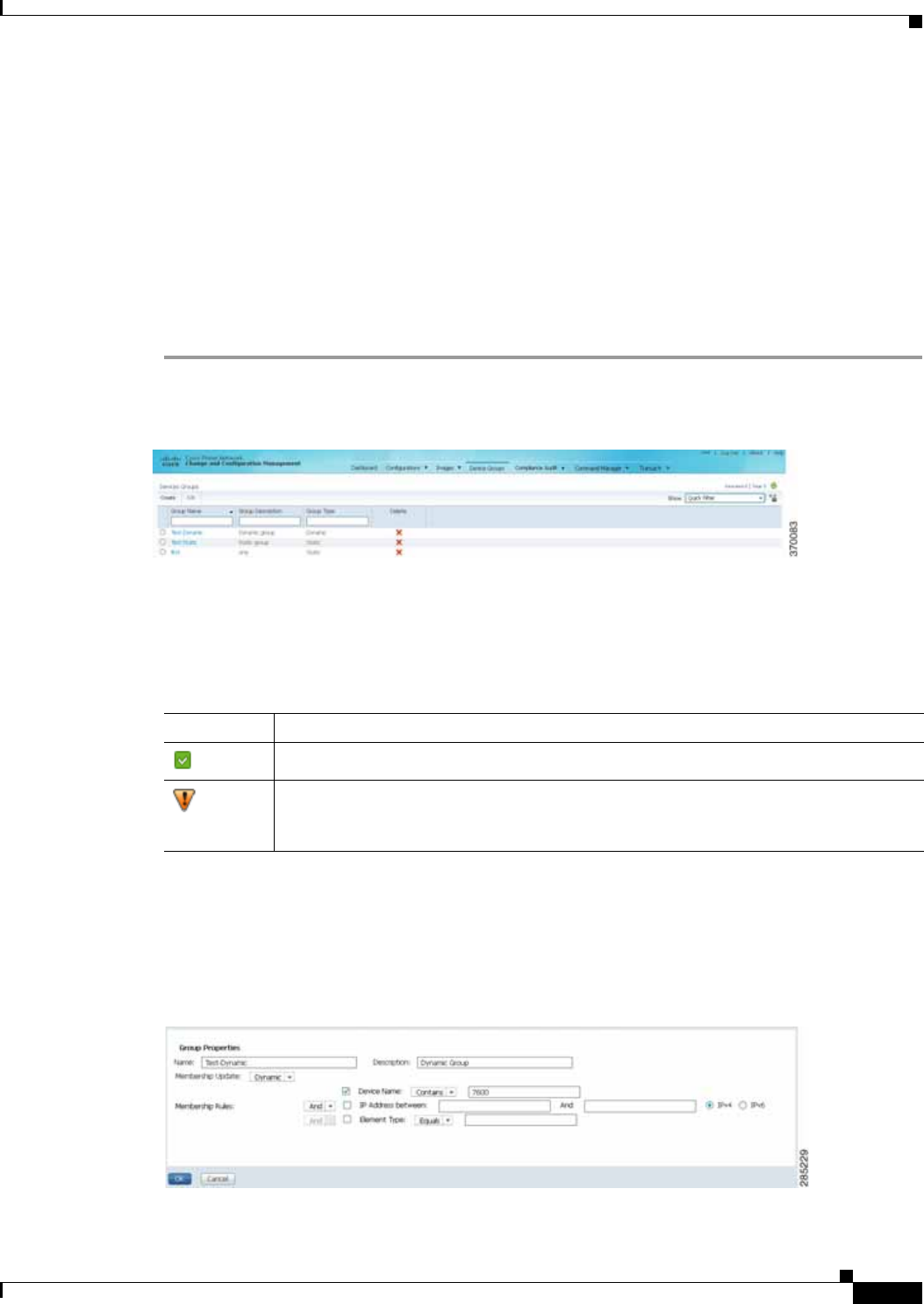
4-9
Cisco Prime Network 4.0 User Guide
OL-29343-01
Chapter 4 Device Configurations and Software Images Set Up Change and Configuration Management
Device Groups Setup Tasks
You can create user-defined device groups for ease of performing operations. A static group contains a
specific set of devices; new devices must be added manually. A dynamic group is populated according
to membership rules; if newly-added devices match the rules, they are automatically added to the group.
If you are backing up the configuration archive or importing software images from devices into the
repository, and a device group changes during the operation, Prime Network updates the job accordingly
such that all the devices available in the group at the time of execution of the job are considered for the
backup or import operation. All other job types are not updated; you must delete and recreate the job.
To view the existing and create new user-defined device groups:
Step 1 Click the Device Groups tab. The Device Groups page appears as shown in Figure 4-1.
Figure 4-1 Device Groups Page
The Device Groups page displays the name, description, and whether the membership is static or
dynamic. To delete a group, click the red X next to the group name.
To view the devices in a group, click the hyperlinked group name to view the devices mapped to the
group in the Group Members page. The device status, IP address and element type is listed. To display
more properties, click the Device Name hyperlink. The status icons are illustrated in the following.
Step 2 To create a new group, click Create and enter the required information. Names must be unique; do not
use the reserved names adminGroup and ROOT-DOMAIN.
Step 3 In the Membership Update drop-down list box, choose Static or Dynamic.
• For dynamic groups, set up a membership rule to indicate which devices must be added to the group.
The following figure provides an example of the Create Device Group page for a dynamic group.
Symbol Description
Device is in operational state.
Device is not in operational state. Most likely the device is in the Maintenance
investigation state or the Unreachable communication state. Click the device hyperlink
and open the device properties popup to see details about the device.
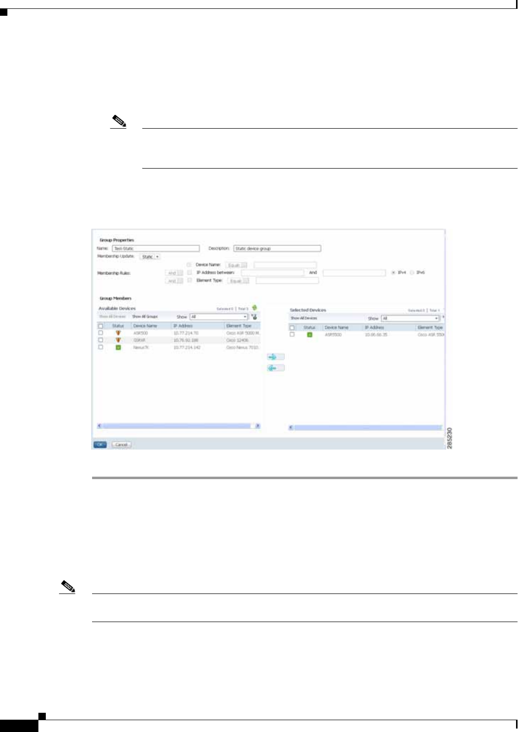
4-10
Cisco Prime Network 4.0 User Guide OL-29343-01
Chapter 4 Device Configurations and Software Images
Use the CCM Dashboard
You can set up membership rules with parameters such as device name, range of device IP addresses,
and the device element type. For example:
Device Name equals 1800
IP Address between 10.77.214.107 And 10.77.214.171 IPv4
Element Type equals Cisco 1801
Note You can choose to include any one or a combination of these parameters in the rule by using
the And/Or operator. Also, you can provide multiple values for the Device Name and
Element Type parameters as a comma-separated list, if required.
• For static device groups, in the Group Members section, under the Available Devices list,
Prime Network lists all the devices that are available in the database. The following figure provides
an example of the Create Device Group page for a static group.
Step 4 Click OK to save the group.
Use the CCM Dashboard
To launch the GUI from a web browser, enter the following URL in the address bar:
https://gateway-IP:8043/ccmweb/ccm/login.htm
Note Change and Configuration Management does not support special characters for any of the editable fields
in the GUI, including filters.
Figure 4-2 shows the CCM Dashboard, which contains four dashlets or subdivisions to display real-time
information about the most frequently used software images, devices with startup and running
configurations that are not in sync, and recent configuration changes.

4-11
Cisco Prime Network 4.0 User Guide
OL-29343-01
Chapter 4 Device Configurations and Software Images Use the CCM Dashboard
Figure 4-2 CCM Dashboard
Dashlet Provides information about:
Top Families Four device families with the highest number of devices in the network. Smaller
groups can be viewed by toggling to the tabular form. From here, you can distribute
and activate software images to a selected family.
Note You may face resizing issues when you hover the cursor over this dashlet, if
you have enabled the Right to Left (Hebrew) settings in your browser.
Configuration
Sync Status (Cisco IOS) Devices for which the startup and running device configurations are in
sync or not in sync. Whenever a Cisco IOS configuration file is retrieved from a
device and copied to the archive, Prime Network compares the latest version of the
startup configuration with the latest version of the running configuration file. If there
is a mismatch, Prime Network adds the device to the list of out-of-sync devices. The
information is refreshed whenever you click the Dashboard.
A “100% Unavailable” message is displayed when there are no Cisco IOS device
images or if the initial configuration sync up setting is not enabled (controlled by the
“Enable/Disable Initial config sync up on restart” setting on the Configuration
Management Settings page).
Configuration
Changes in the
Last Week
Number of device configuration changes detected for each day of the previous week.
This dashlet is empty when configuration change notification is not enabled
(controlled by the “Enable/Disable Event-Triggered Config Archive” setting on the
Configuration Management Settings page).
Most Recent
Configuration
Changes
Last five device configuration changes that were made to devices in the network. This
dashlet is empty if configuration change notification is not enabled. It is controlled
by the “Enable/Disable Event Triggered Config Archive” setting on the
Configuration Management Settings page (see Change Configuration Managemennt
Global Settings, page 4-61).
The Commit ID and Diff columns apply only to Cisco IOS XR devices. Other device
types will display N/A in those columns.

4-12
Cisco Prime Network 4.0 User Guide OL-29343-01
Chapter 4 Device Configurations and Software Images
Device Configurations
Use the following icons to toggle between different views in the Top Families, Configuration Sync
Status, and Configuration Changes in the Last Week dashlets.
Device Configurations
The following topics explain how to work with device configurations:
• What is In the Archive?, page 4-12
• Protect Configurations in the Archive, page 4-13
• Find Out What is Different Between Configurations, page 4-14
• Copy a Configuration File to a Central Server, page 4-16
• Are Running and Startup Configs Mismatched? (Cisco IOS and Cisco Nexus), page 4-17
• Copy the Device Files to the Archive (Backups), page 4-18
• Fix a Live Device Configuration (Restore), page 4-22
• Clean Up the Archive, page 4-25
• Find Out What Changed on Live Devices, page 4-25
What is In the Archive?
Choose Tools > Change and Config Mgmnt to open Change and Configuration Management.
Choose Configurations > Archives to view the contents of the archive. The CM archive maintains
copies of device configuration files, storing them in the Prime Network database. Configuration files are
stored in readable format, as received from the device. You can edit existing archive files and save for
deployment at a later time. The edited archive files are available in the Edited Archive tab. The total
number of archives available in the Prime Network database is also displayed in the header. The
configuration, after deployment, can also be restored to the original state. Users can only see devices that
are in their device scope. For enhanced security, you might be prompted to enter your device access
credentials when you try viewing device details or when you try performing configuration changes on
devices. This option is enabled if, from the Prime Network Administration > Global Settings >
Security Settings > User Account Settings > Execution of Configuration Operations, you checked
the option Ask for user credentials when running configuration operations.
The Archived Configurations page displays the following information about each configuration file.
Icon Description
Displays the details in the form of a pie or bar chart. If you hover your mouse cursor over
a section in the pie chart, a tooltip displays the information associated with that section.
Displays the details in a tabular form.

4-13
Cisco Prime Network 4.0 User Guide
OL-29343-01
Chapter 4 Device Configurations and Software Images Device Configurations
Protect Configurations in the Archive
Table 4-1 Configuration Information Displayed on Archived Configurations Page
Field Description
Device Name Name of device. Click the icon next to the device name to open a popup that
displays device properties. Additional information is listed depending on the
device type:
• Current active packages on the device—For Cisco IOS XR devices
• Active kickstart images—For Cisco Nexus series devices
• Priority list—For Cisco ASR 5000 series devices. The priority list displays
various combinations of a configuration file and an image file in priority
order for the device.
Version An internally-used number. A version will not have an associated configuration
file under the following circumstances:
• The associated configuration file was deleted from the archive.
• The associated configuration file has not yet been copied to the archive.
(Prime Network supports queuing change notifications and copying the
configuration files to the archive at a later time. See Change Image
Management Global Settings, page 4-66.)
Click a version number hyperlink to launch the Device Configuration Viewer,
from which you can view the contents of a configuration file.
Type Type of configuration:
• Cisco IOS and Cisco Nexus series devices—Running or Startup
• Cisco IOS XR devices—Running or Admin
• Cisco ASR 5000 series devices—Running or Boot. For boot configuration,
the version is always displayed as 1.
• Cisco CPTdevices—Startup
Vendor Specifies the device vendor: Cisco or non-Cisco device.
Date Changed Date and time of last change, displayed accordingly to the local time zone
settings of the client.
For Cisco CPT and Cisco ASR 5000 series devices, this field displays N/A.
Label User-assigned archive labels.
Running Image The software image currently running on the device.
Context / Module /
Priority For Cisco Nexus series devices, this field displays the virtual device context
(VDC) name.
For Cisco 7600 series devices, this field displays the module name.
For Cisco ASR 5000 series devices, this field displays the boot configuration
files with their priorities.
For other devices, this field displays N/A.
Comments User-assigned free text.
Commit Id (Cisco IOS XR only) ID that identifies the last configuration change on the
device (maximum number saved is 100).

4-14
Cisco Prime Network 4.0 User Guide OL-29343-01
Chapter 4 Device Configurations and Software Images
Device Configurations
Assigning labels to configuration files is a clear, simple way to identify important configurations and
convey critical information. You can manage labels by choosing Labels > Manage.
• Adding a label adds it to the catalog where it is made available to all users. Add labels by clicking
Add Row.
• Deleting a label unassigns the label from configurations that are using it. Likewise, if you edit a
label, the change is applied to all configurations using the label.
• Unassigning a label does not delete the label from the catalog.
• Labels with the “do not purge” property will not be purged from the archive (the delete action is
disabled). When calculating the total number of archives to see if the maximum has been reached
and archives should be purged, CM does not include configurations with this label in the total (see
Change Configuration Managemennt Global Settings, page 4-61).
Editing an Archive Configuration
You can edit an existing device archive file and save the the edited file. This edited archived file is stored
in the Prime Network database, and the edited file can be deployed at any time. This can be viewed from
the Edited Archive tab, in the Archive page. Every time you edit and save an existing file, a new version
is added in the database, and is also listed in the Edited Archive page.
Note The option to edit existing device archive file and save the edited file is not available for non-Cisco
devices.
Edit archive files following the procedure below:
Step 1 From the Archive page, choose a configuration file, and click Edit.
Step 2 Edit and save the configuration file.
An edited archive version is created. This edited version will belong to the same configuration type as
that of the original archive file.
The edited archive files can be restored to the devices.
Find Out What is Different Between Configurations
Prime Network allows you to compare two configuration files that are saved in the archive and display
them side by side, highlighting configuration differences and allowing you to move between them.
Prime Network excludes a small set of commands by default, such as the NTP clock rate (which
constantly changes on a managed network element but is not considered a configuration change). You
can change the excluded commands list as described in Change Configuration Managemennt Global
Settings, page 4-61. Additions, deletions, and excluded values are color-coded as shown in the following
example.

4-15
Cisco Prime Network 4.0 User Guide
OL-29343-01
Chapter 4 Device Configurations and Software Images Device Configurations
Figure 4-3 Compare Configurations Dialog Box
You can compare any types of configurations as long as they run on the same operating system. However,
you cannot compare a Cisco IOS configuration with Cisco IOS XR configuration.
The following are typical scenarios for using the compare function:
• Compare the latest and next-to-latest configuration to see the most recent change.
• Compare Cisco IOS running and startup configurations to see how they are out of sync.
• Compare the configurations on two different devices to find out how they are different.
• Compare the configurations after eliminating excluded lines from comparison.
Note When you are trying to compare an archive with an active startup, running, or admin configuration, if
there is a change in the device configuration, Prime Network initiates a backup job and creates a latest
version of the device configuration file. You can view the latest version of the configuration file in the
Archived Configurations page.
To compare configurations:
Step 1 Choose Configurations > Archives.
Step 2 Locate the archives you want to compare. You can click the Version hyperlink next to a device to open
the Device Configuration Viewer and quickly view the contents of the configuration file.

4-16
Cisco Prime Network 4.0 User Guide OL-29343-01
Chapter 4 Device Configurations and Software Images
Device Configurations
Step 3 You can choose to do the following:
Copy a Configuration File to a Central Server
You can export configurations to an FTP or SFTP server that is specified on the Configuration
Management Settings page. They are exported as a .cfg (configuration) file.
Configuration files are saved using the following format:
deviceName-configurationType-version-configChangeTimestamp.cfg
For example, the following file would contain the 18th version of a running configuration for the device
named 7200-5, saved on March 27, 2010 at 2:40:30 P.M:
7200-5-RUNNING_CONFIG-18-2010327144030.cfg
Note Export of configuration files of IPv6 devices to servers running Windows OS is not supported.
Before You Begin
Make sure of the following:
• Export location and required credentials, and (for emails) SMTP host and port are configured on the
Configuration Management Settings page.
• Specified FTP or SFTP server must have sufficient free space to accommodate the exported
configurations. Also, the destination subdirectory on the FTP or SFTP server must have the required
permissions.
To export configuration files:
Step 1 Choose Configurations > Archives and locate the archives you want to export. You can click the
Version hyperlink next to a device to open the Device Configuration Viewer and quickly view the
contents of the configuration file.
Step 2 Click Export and set the desired schedule and enter the e-mail ID(s) to which to send a notification after
the scheduled export job is complete. For two or more users, enter a comma-separated list of e-mail IDs.
A notification e-mail is sent based on the e-mail option specified in the Configuration Management
Settings page.
Note The time you specify here to schedule the export job is the server time.
Device Type or OS Supported Function
For Cisco IOS XR devices Compare > To Active Running or Compare > To Active Admin
Cisco IOS device Compare > To Active Startup or Compare > To Active Running
Cisco ASR 5000 series device Compare > To Active Boot or Compare > To Active Running
All Compare > Selected Archives

4-17
Cisco Prime Network 4.0 User Guide
OL-29343-01
Chapter 4 Device Configurations and Software Images Device Configurations
Step 3 Click Export. The export job is created and you are redirected to the Job Manager page, where you can
monitor the status of the job.
Are Running and Startup Configs Mismatched? (Cisco IOS and Cisco Nexus)
Cisco IOS and Cisco Nexus series devices contain a startup and running configuration file. The startup
configuration is loaded when a device is restarted. Ongoing changes to the device are applied to the
running configuration. As a result, unless the running configuration is saved as the startup configuration,
upon a device restart, any changes would be lost. It is therefore important to ensure that the device startup
and running configurations are in sync. When Prime Network synchronizes a file, it overwrites the
startup configuration on the device with the configuration that is currently running on the device.
Whenever a configuration file is retrieved from a device and copied to the archive (that is, backed up),
Prime Network compares the latest version of the startup configuration with the latest version of the
running configuration file. If there is a mismatch, Prime Network adds the device to the list of
out-of-sync devices.
For Cisco Nexus series devices, CM backs up the startup and running configurations for all VDCs
configured in the device. If there is a mismatch between the startup and running configurations of a
VDC, CM creates an out-of-sync entry for that VDC.
Note The synchronize operation affects only the configurations running on the device. It does not affect any
configuration files that are saved in the archive. Configuration sync is not applicable for Cisco CPT and
Cisco ASR 5000 series devices.
The Dashboard maintains a Configuration Sync Status pie chart that shows how many devices have
out-of-sync startup and running configuration files. When you click the pie chart (or choose
Configurations > Synchronize), you are directed to the Out of Sync Devices page, where
Prime Network lists all of the out-of-sync devices in tabular format. The information is refreshed
whenever you choose Configurations > Synchronize.
Before You Begin
Make sure the specified FTP or SFTP server must have sufficient free space to accommodate the
exported configurations. Also, the destination subdirectory on the FTP or SFTP server must have the
required permissions.
To view differences and synchronize configurations:
Step 1 Choose Configurations > Synchronize. Prime Network lists all out-of-sync devices, the date and time
when the device configurations were last changed, and when the files were last archived. Figure 4-4
provides an example. The date and time are displayed according to the local time zone settings of the
client.

4-18
Cisco Prime Network 4.0 User Guide OL-29343-01
Chapter 4 Device Configurations and Software Images
Device Configurations
Figure 4-4 Configuration Synchronization - Out of Sync Devices Page
Step 2 Click the Compare icon to launch the Compare Configuration window, which provides a side-by-side
view of the two configurations and highlights the differences.
Step 3 Choose the network elements you want to synchronize. This directs Prime Network to overwrite the
startup configuration on the device with the configuration that is currently running.
Step 4 Click Synchronize. The Schedule Synchronization page opens.
Step 5 Set the desired schedule and enter the e-mail ID(s) to which to send a notification after the scheduled
synchronization job is complete. For two or more users, enter a comma-separated list of e-mail IDs. The
time you specify here to schedule the synchronization job is the server time.
Note You might be prompted to enter your device access credentials. This option is enabled if, from
the Prime Network Administration > Global Settings > Security Settings > User Account
Settings > Execution of Configuration Operations, you checked the option Ask for user
credentials when running configuration operations. This is an enhanced security measure
restrict access to devices.
Step 6 Click Synchronize. Prime Network schedules the job and redirects you to the Jobs page, where you can
monitor the status of the job.
Copy the Device Files to the Archive (Backups)
These topics describe how to automatically and manually back up configuration files to the archive:
• Automatic Backups and Manual Backups
• Manually Backing Up Configuration Files
Backing up a device configuration entails getting a copy of the configuration file from the device, and
copying that file to the configuration archive. As part of the backup procedures, it is compared with the
latest archived version of the same type (e.g. running with running, startup with startup). A new version
of the file is archived only if the two files are different. If the number of archived versions exceeds the
maximum, the oldest archive is purged (according to the values on the Configuration Management
Settings page). Configurations marked with a “do not purge” label are not removed from the archive by
the auto-purging procedures.
The backup procedure is also when Prime Network identifies out-of-sync devices.
The backup operation includes:
• Cisco IOS XR devices: Includes active packages. CCM does not back up running configurations for
Cisco IOS XR devices that are managed with non-system user credentials; because copy command
is not available in the command-line interface (CLI) for non-system users.

4-19
Cisco Prime Network 4.0 User Guide
OL-29343-01
Chapter 4 Device Configurations and Software Images Device Configurations
• Cisco Nexus series devices: Startup and running configurations for all VDCs configured in the
device.
• Cisco 7600 series devices with an ACE card: Startup and running configurations of the ACE card.
• Cisco ASR 5000 series devices: Boot configuration file (Prime Network always overwrites the
existing boot configuration in the archive)
Automatic Backups and Manual Backups
Table 4-2 describes the methods you can use to back up configuration files to the archive. None of these
methods are enabled by default. Choose the method that is appropriate to your network and how often
changes are made to it. For more information, see Configuration Management Setup Tasks, page 4-5.
Note While scheduling automatic backup operations, you might be prompted to enter your device
access credentials. The device credentials are taken from the Configuration Settings. This option
is enabled if, from the Prime Network Administration > Global Settings > Security Settings
> User Account Settings > Execution of Configuration Operations, you checked the option
Ask for user credentials when running configuration operations. This is an enhanced
security measure restrict access to devices.
Table 4-2 Methods for Archiving Configuration Files
Method Description
Initial Sync Activates CM to perform an initial synchronization of the CM archive files with the configurations that are
running on the network devices. If this setting is enabled, whenever the Prime Network gateway is restarted,
CM performs this synchronization. This behavior is controlled by the Enable Initial Config sync up setting on
the Configuration Management Settings page. See Change Image Management Global Settings, page 4-66.
Manual A user-driven backup that is controlled from the Configurations > Backup page. Performing a backup from
the Backup page overrides all other archive settings. You can schedule the file backup to occur immediately
or according to a schedule.
Note Any backups scheduled using this method are completely independent of any schedules for ongoing
archiving. However, users can only back up devices that are within their scope, and if they have a
sufficient device scope-based role.
See Manually Backing Up Configuration Files, page 4-20.

4-20
Cisco Prime Network 4.0 User Guide OL-29343-01
Chapter 4 Device Configurations and Software Images
Device Configurations
Manually Backing Up Configuration Files
Files are automatically backed up to the archive according to the values on the Configuration
Management Settings page. To perform an on-demand backup of configuration files to the archive:
Step 1 Choose Configurations > Backup. Prime Network lists all devices with the following status symbols as
shown in Figure 4-5.
Step 2 Choose the devices with files you want to back up.
Ongoing • Event-Driven—Backs up device files when Prime Network receives a configuration change notification.
Use this method if you consider every configuration file change to be significant. This is controlled by the
Enable Event-triggered Config Archive setting on the Configuration Management Settings page.
For this form of backup, you can choose one of the following methods for performing the archiving:
–
Back up the files to the archive immediately when a change is detected.
–
Queue the changes and back up the files to the archive according to a schedule.
Both of these settings are controlled from the Configuration Management Settings page.
If you are using event-driven archiving, you should also make sure that exclude commands are properly
configured. Exclude commands are commands that Prime Network ignores when comparing
configurations, and they are controlled from the Settings page. Using this mechanism eliminates
unnecessary file backups to the archive.
• Periodic—Archives device files every 72 hours and this is configurable. A new archive is created only if
the newly-collected device configuration is different from the last version in the archive. Use this method
if configurations change frequently and the changes are not important to you. This setting is controlled
by the Enable Periodic Config Backup setting on the Configuration Management Settings page.
Note This CM collection is independent of the Prime Network inventory collection.
See Change Configuration Managemennt Global Settings, page 4-61.
Table 4-2 Methods for Archiving Configuration Files (continued)
Method Description
Symbol Description
Device is available for backup.
Device is not available for backup. The device is most likely in the Maintenance
investigation state or the Unreachable communication state. Click the device
hyperlink and open the device properties popup to see details about the device.

4-21
Cisco Prime Network 4.0 User Guide
OL-29343-01
Chapter 4 Device Configurations and Software Images Device Configurations
Figure 4-5 Configuration Backup Page
Step 3 To choose devices from a specific device group, click Select Groups. Click the hyperlinked device group
name to view the list of devices that belong to the group.
Step 4 Select the required device group in the Device Groups page and click OK. The devices that belong to
the selected device group are highlighted in the Configuration Backup page. You can also schedule a
backup simultaneously for all the devices existing in a group:
• Select a device group and click Backup Groups.
• Enter the scheduling information as explained after Step 5 and click Backup Groups.
Step 5 In the Configuration Backup page, click Backup to configure the backup schedule. By default, the
backup is performed as soon as possible. Other schedule choices (once, periodically, weekly, and so
forth) are activated when you deselect Start as Soon as Possible. The time you specify here to schedule
the synchronization job is the server time.
Note You might be prompted to enter your device access credentials. This option is enabled if, from
the Prime Network Administration > Global Settings > Security Settings > User Account
Settings > Execution of Configuration Operations, you checked the option Ask for user
credentials when running configuration operations. This is an enhanced security measure
restrict access to devices.
Step 6 Enter the e-mail ID(s) to which to send a notification after the schedule backup job is complete. For two
or more users, enter a comma-separated list of e-mail IDs. A notification e-mail is sent based on the
e-mail option specified in the Configuration Management Settings page.
Step 7 Click Backup. Prime Network schedules the job and redirects you to the Jobs page, where you can
monitor the status of the job.
Note If a backup is scheduled for an entire device group and if there is a change in the group by
addition or deletion of devices after job creation, Prime Network updates the job accordingly
such that all the devices available in the group at the time of execution of the job are considered
for backup.

4-22
Cisco Prime Network 4.0 User Guide OL-29343-01
Chapter 4 Device Configurations and Software Images
Device Configurations
Fix a Live Device Configuration (Restore)
CCM performs the configuration restore operation in either overwrite or merge mode, as described in
the following. As part of restore operation, the configuration files are backed up again after the restore
procedure is complete.
• Overwrite mode—CCM overwrites the existing configuration on the device with a configuration file
from the archive. After the restore operation is performed, the device configuration is identical to
the configuration that was chosen from the archive.
The following devices support overwrite mode:
Cisco Catalyst 3550 Series Switches
Cisco Catalyst 3560 Series Switches
Cisco Catalyst 3750 Series Switches
Cisco Catalyst 6500 Series Switches (IOS)
Cisco 800 Series Routers
Cisco 1800 Series Routers
Cisco 1700 Series Routers
Cisco 2600 Series Multiservice Platform Routers
Cisco 2800 Series Integrated Services Routers
Cisco 3700 Series Multiservice Access Routers
Cisco 3800 Series Integrated Services Routers
Cisco 7200 Series Routers
Cisco 7600 Series Routers
Cisco 10000 Series Routers
Cisco 12000 Series Routers (IOS)
Cisco ASR 901 Series Routers
Cisco ASR 903 Series Routers
Cisco MWR 2941 Router
For Cisco IOS XR devices, the restore operation rolls back the configuration file to a commit ID
associated with the selected archived configuration. If no commit ID is associated with the selected
archived version, the restore will fail.
For all other devices supported by CCM, restore operations in overwrite mode is not supported.
• Merge mode—CCM merges the selected configuration file from the archive with the configuration
on the device. New commands in the archived version—that is, commands that are not in the
device’s current configuration—are pushed to the device. After the restore operation, the device
configuration file retains its original commands, but it also contains new commands from the
archived version.
Note The restore operation is not applicable to boot configuration files on Cisco ASR 5000 series devices.
By default, Prime Network uses the restore mode setting (overwrite or merge) that is specified in the
Configuration Management Settings page (see Change Configuration Managemennt Global Settings,
page 4-61. However, you can modify the default mode while scheduling the restore operation. If you
have selected the overwrite mode, you can use the Use Merge on Failure option to restore the files in
merge mode, if overwrite mode fails.
If you select the devices by checking the check box next to Devices (in the table headline), only the first
100 devices in the first page are selected. Click Next to move to the next 100 devices. If you filter the
devices based on a parameter, only the filtered details are displayed, and by default, no row is selected.
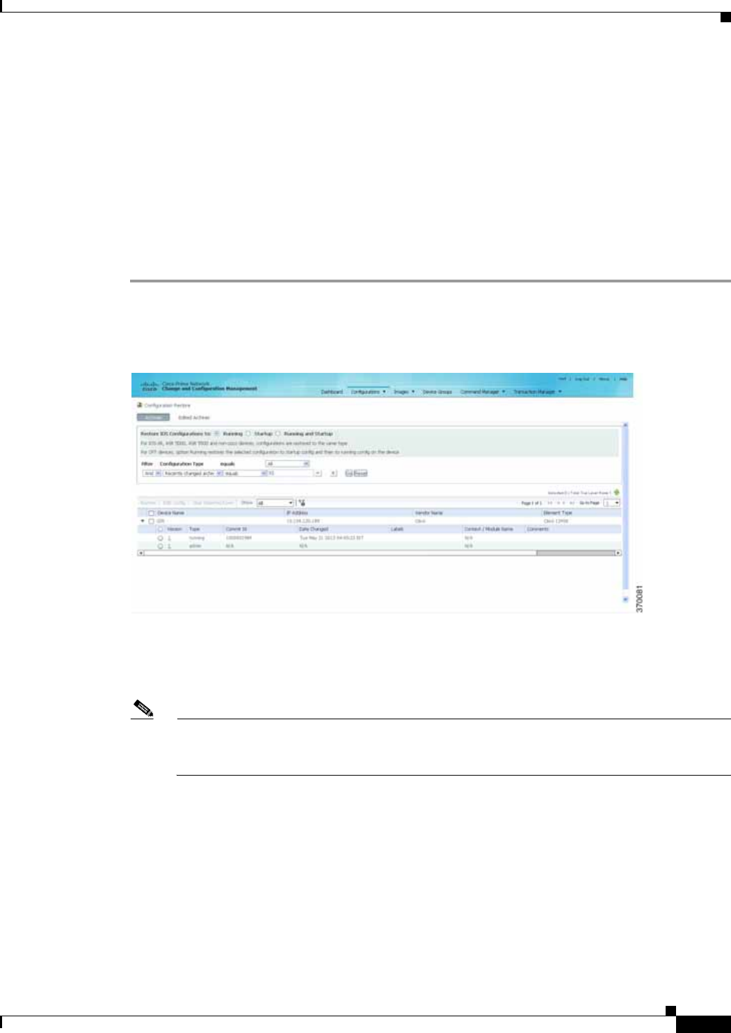
4-23
Cisco Prime Network 4.0 User Guide
OL-29343-01
Chapter 4 Device Configurations and Software Images Device Configurations
If you selected all the entries in a page, and then deselected one or few options from the selection, and
then move to the subsequent pages to select all the devices from the Devices (in the table headline), the
selection in the previous page disappears.
Before You Begin
• Make sure you have installed Flash Player version 10 or higher to view the Configuration Restore
page.
• Make sure you have the permissions to perform the restore operation. You will not be allowed to
schedule a restore job, if you do not have permissions.
To restore a configuration:
Step 1 Choose Configurations > Restore. Prime Network lists all configuration files in the archive. Figure 4-6
shows an example of a filtered page.
Figure 4-6 Configuration Restore Page
Step 2 (Cisco IOS only) Specify the type of configuration files you want to restore: Running, Startup, or both.
If you choose to restore to startup configuration, Prime Network will first copy the file to running
configuration and then to startup configuration.
Note Cisco IOS XR, Cisco ASR 5000 series, and non-Cisco device configuration files are always
restored to the same type. For Cisco CPT devices, the Running option restores the selected
configuration to startup config and then to running config on the device.
Step 3 Choose the configuration files you want to restore. You can click the arrow mark next to the device name
to view the different versions of the configuration file of the device. You can also click the Version
hyperlink to view the contents of a file. If the file is a binary file, clicking the version hyperlink does not
open the various versions of the configuration file.
If you prefer to restore an edited archive file, open the Edited Archive tab. Select the files and click Next.
The list of devices that belong to the same device family with respect to the selected edited configuration
is displayed. Select the required devices. Skip to Step 5.
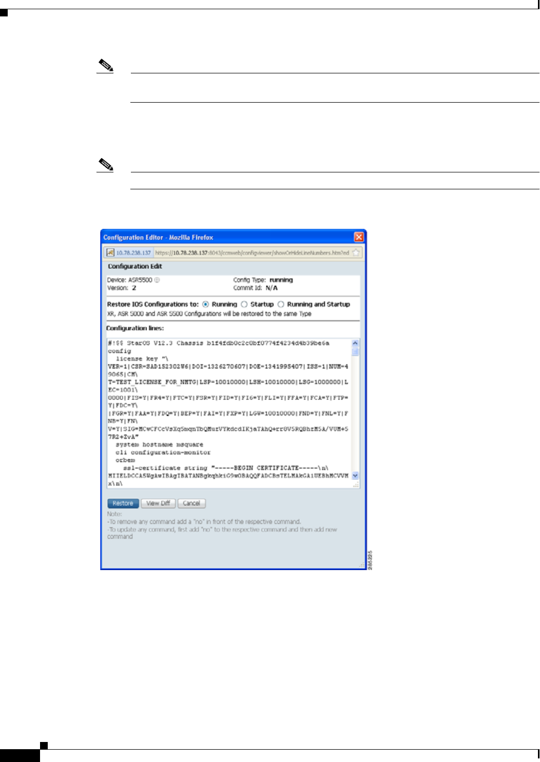
4-24
Cisco Prime Network 4.0 User Guide OL-29343-01
Chapter 4 Device Configurations and Software Images
Device Configurations
Note Edited files are restored only in merge mode. If you are restoring to startup mode on the devices
ASR 901, ASR 903, and MWR2941, the restore procedure is performed on overwrite mode.
Step 4 If you want to edit a file before restoring it, click Edit Config (edited files are restored only in merge
mode). You can view the details of the selected configuration file in the Configuration Editor page as
shown in Figure 4-7.
Note If you selected non-Cisco devices, the Edit Config button is disabled.
Figure 4-7 Configuration Edit
Edit the configuration lines, as required. Note the following:
• To remove a command, add no in front of the command.
• To update a command, add no in front of the command and then add the new command.
Step 5 Click Restore. The Config Restore Schedule dialog box opens.
Step 6 (Optional) Override the default transport protocol and default restore mode.
Step 7 Enter a comma-separated list of e-mail ID(s) to which to send a notification after the scheduled restore
job is complete.

4-25
Cisco Prime Network 4.0 User Guide
OL-29343-01
Chapter 4 Device Configurations and Software Images Device Configurations
Note You might be prompted to enter your device access credentials. This option is enabled if, from
the Prime Network Administration > Global Settings > Security Settings > User Account
Settings > Execution of Configuration Operations, you checked the option Ask for user
credentials when running configuration operations. This is an enhanced security measure to
restrict access to devices.
Step 8 Click Restore. Prime Network schedules the job and redirects you to the Jobs page, where you can
monitor the status of the job.
Clean Up the Archive
Deleting a file removes it from the archive. You cannot delete an archived file if:
• It is marked “do not purge.”
• Deleting it would bring the number of versions below the minimum number of versions that must
be retained (as specified on the Configuration Management Settings page).
When a device is removed from Prime Network, its configuration files are also removed from the
archive.
To delete a configuration file from the archive:
Step 1 Choose Configurations > Archives.
Step 2 Choose the configuration file you want to delete. You can click the Version hyperlink to verify the
contents of the configuration file.
Step 3 To delete a single configuration file, click the delete icon (red X) at the end of the row. If the delete icon
is disabled, this means the archive is assigned a label that is marked “do not purge.” To delete this type
of configuration, you must first unassign the label from the configuration.
Step 4 To delete multiple configuration files, select the required files and then click the Delete button in the
table header.
Step 5 Confirm your choice. Prime Network schedules the job and redirects you to the Jobs page, where you
can monitor the status of the job.
Find Out What Changed on Live Devices
The Change Logs page displays a list of the latest device configuration changes detected by
Prime Network. How Prime Network responds to these changes depends on the values on the
Configuration Management Settings page. By default, Prime Network does not get new information
from the device and copy it to the archive when a change occurs, but you can set it to do so. See Change
Configuration Managemennt Global Settings, page 4-61.
All users can view the change logs, regardless of the user access role or assigned device scopes. To view
the latest changes, choose Configurations > Change Logs. Figure 4-8 provides an example.

4-26
Cisco Prime Network 4.0 User Guide OL-29343-01
Chapter 4 Device Configurations and Software Images
Software Images
Figure 4-8 Configuration Change Logs
The Configuration Change Logs page displays change information, sorted according to the latest time
stamp. (For a description of common fields, see Device Configurations, page 4-12.) The date and time
stamps are displayed according to the local time zone settings of the client. These fields are specific to
the Configuration Change Logs page:
Software Images
The following topics explain how to work with software images and packages:
• Add New Images to the Repository, page 4-27
• New Devices: Create an Image Baseline, page 4-28
• Distribute Images and Make Sure They Will Work, page 4-29
• Activate Cisco IOS Software Images, page 4-34
• Perform Cisco IOS XR Software Package Operations, page 4-37
Field Description
Diff (Cisco IOS XR only) Displays only the commands that were changed. For long
text, hover the cursor over the hyperlink to display the entire contents.
Compare Launches the Compare Configuration window, which displays the entire original
and changed files side by side. This data is generated only if file versions are
available.
Additions and deletions are color-coded. From here, you can:
• Click Show All Lines or Only Differences to display the entire file contents
or just the differences between the two files.
• Click Previous Diff or Next Diff to jump forward or backward to the previous
or next difference between the two files.
• Click the arrow buttons or enter the page number to jump forward or backward
to view the file contents that are running across pages.
• Click Differences Without Excluded Lines to eliminate excluded lines from
comparison.

4-27
Cisco Prime Network 4.0 User Guide
OL-29343-01
Chapter 4 Device Configurations and Software Images Software Images
• Clean Up the Repository, page 4-44
Add New Images to the Repository
Images are copied to the storing directory specified on the Image Management Settings page.
Prime Network verifies whether the file contents are different from the previous version in the
repository. If there are no differences, the image is not added to the repository. By default, the storing
directory is PRIME_NETWORK_HOME/NCCMComponents/NEIM/images/, where
PRIME_NETWORK_HOME is the Prime Network installation directory (by default,
/export/home/network-user; where network-user is the operating system user for the Prime Network
application and an example of network-user is network310). From there, they are imported into the
repository.
Note Before importing images, make sure internet connectivity is available to the server; otherwise, the
imported images will not be populated with RAM, boot ROM, and feature set.
When you download an image from Cisco.com, Prime Network creates a job for the download. The job
information is saved, along with other job information, in the database.
To import images into the Prime Network image repository:
Step 1 Choose Images > Repository.
Step 2 Choose the appropriate method:
Step 3 Select the images and import them. Change and Configuration Management redirects you to the Jobs
page, where you can monitor the status of the import job.
Step 4 Choose Images > Repository again to refresh the list of images.
Step 5 If a field displays NA, the image attributes were not available from the image header. (If pre-existing
filters are still in use, you may need to click Clear Filter.) We recommend that you manually enter the
information to ensure the accuracy of the upgrade analysis.
Step 6 Delete files from the storing directory (if applicable) to free space for future imports.
After the import, you can also add informational text to the Comments field. Normally at this point you
will distribute the images; see Distribute Images and Make Sure They Will Work, page 4-29.
To import from: Choose: Notes
Cisco.com web site From Cisco.com Make sure the Cisco.com credentials are set on the
Image Management Settings page. You must enter
a device type, software version, and feature set.
Another IPv4 or IPv6
gateway server From External
Repository The GUI will display available images, their size,
and whether they already exist in the repository.
Change and Configuration Management displays
all images or packages (bin, pie, smu, and so on)
from the directory specified in the Image
Management Settings page, and also from its sub
directory in order to support tar files.
A file system on the
local gateway server From File System

4-28
Cisco Prime Network 4.0 User Guide OL-29343-01
Chapter 4 Device Configurations and Software Images
Software Images
New Devices: Create an Image Baseline
Use this method to create an image baseline—that is, import software images directly from existing
devices to the Prime Network image repository. This is useful when you add devices from a new device
series or family. This information is imported:
• Cisco IOS devices: Currently-running images. For Cisco 7600 series devices with ACE cards: ACE
card images in the Cisco 7600 supervisor module filesystem (FTP, TFTP, and SCP are all
supported).
• Cisco IOS XR devices: pie and .vm files corresponding to active packages.
Note Image baseline is not applicable for Cisco CPT devices.
To import images from devices into the Prime Network image repository:
Step 1 Choose Images > Repository.
Step 2 From the Import drop-down list, choose From Devices. The Devices dialog box displays information
about the device. For long texts in the Element Type, Software Version, and Running Image fields,
hover the cursor over the hyperlink to display the entire contents.
Step 3 To import images from devices of a specific group, click Select Groups. Click the hyperlinked device
group name to view the list of devices that belong to the group. See Device Groups Setup Tasks, page 4-9
for more information on user-defined device grouping.
Step 4 Select the required device group in the Device Groups page and click OK.
The devices that belong to the selected device group are highlighted in the Devices page. You can also
import all the devices existing in a group. To do so:
–
Select a device group and click Import from Group.
–
Enter the scheduling information as explained after Step 5 and click Import from Group.
Step 5 In the Devices page, click Import. A scheduler popup window appears.
Note You might be prompted to enter your device access credentials. This option is enabled if, from
the Prime Network Administration > Global Settings > Security Settings > User Account
Settings > Execution of Configuration Operations, you checked the option Ask for user
credentials when running configuration operations. This is an enhanced security measure to
restrict access to devices.
Step 6 Enter the scheduling information. By default, jobs are scheduled to run as soon as possible.
Note The time you specify here to schedule the import job is the server time.
Step 7 If you do not want to use the default transfer protocol, select a different protocol:
• TFTP (unsecured; Cisco ASR 5000 series devices use this protocol for importing images)
• SFTP/SCP (secured; Cisco IOS XR devices and Cisco Nexus 5000 and 7000 series devices use
SFTP, and Cisco IOS devices use SCP)
• FTP (unsecured)

4-29
Cisco Prime Network 4.0 User Guide
OL-29343-01
Chapter 4 Device Configurations and Software Images Software Images
Step 8 If you have selected two or more devices, click one of the following to specify the operation mode:
• Parallel Order—Imports images from all devices at the same time.
• Sequential Order—Allows you to specify the order of the devices to import the images from. You
can do so by moving the devices up and down in the Device Order box.
Note The Device Order box will not be available, if the number of devices is more than 300.
Prime Network sequences the devices based on the default order (that you used while selecting
the devices.)
Step 9 Enter the e-mail ID(s) to which to send a notification after the import job is complete. For two or more
users, enter a comma-separated list of e-mail IDs. A notification e-mail is sent based on the e-mail option
specified in the Image Management Settings page.
Note Before you enter the e-mail ID(s), ensure that you have set up the SMTP host and SMTP port in
the Image Management Settings page (see Change Image Management Global Settings,
page 4-66). The e-mail ID(s) configured in the Image Management Settings page, if any, will be
displayed by default. You can modify the e-mail ID(s) if required.
Step 10 Click Import. Prime Network redirects you to the Jobs page, where you can monitor the status of the
import job.
Note If you chose to import all devices from a group and if there is a change in the group by addition
or deletion of devices after job creation, Prime Network updates the job accordingly such that
all the devices available in the group at the time of execution of the job are considered.
Step 11 Choose Images > Repository again to refresh the list of images. If any of the image information could
not be retrieved, the field will display NA. (If pre-existing filters are still in use, you may need to click
Clear Filter.)
Step 12 If a field displays NA, the image attributes were not available from the image header. (If pre-existing
filters are still in use, you may need to click Clear Filter.) We recommend that you manually enter the
information to ensure the accuracy of the upgrade analysis.
Step 13 Delete files from the storing directory (if applicable) to free space for future imports.
After the import, you can also add informational text to the Comments field. Normally at this point you
will distribute the images; see Distribute Images and Make Sure They Will Work, page 4-29.
Distribute Images and Make Sure They Will Work
Prime Network copies an image to a network element without activating it. This lets you perform these
tasks before activating the image:
• Find out if there is insufficient memory, clear the disk space for distributing the image or package
• Do an upgrade analysis to check the suitability of the device for the chosen image

4-30
Cisco Prime Network 4.0 User Guide OL-29343-01
Chapter 4 Device Configurations and Software Images
Software Images
If appropriate, the images can be activated as part of the distribution job, and these tasks can also be
performed:
• Commit Cisco IOS XR (so that changes are saved across device reloads).
• Perform a warm upgrade, where one Cisco IOS image can read in and decompress another
Cisco IOS image and transfer control to this new image (thus reducing the downtime of a device
during planned software upgrades and downgrades).
Note You can perform a warm upgrade only on Cisco IOS devices 12.3(2)T or later, such as 12.4T,
15.0, 15.1T, and for ISR 800/1800/2800/3800 series and 1900/2900/3900 series.
• Perform an in-service software upgrade (ISSU) for Cisco ASR 903 devices to update the router
software with minimal service interruption. CCM performs a single command upgrade that installs
a complete set of sub-packages using one command. Before using CCM to perform a single
command upgrade, the ASR 903 device must already be booted in sub-package mode. The device
must be configured in SSO redundancy mode.
Note Cisco ASR 903 devices must be booted in sub-package mode only through boot flash and
not through any sub-directories of boot flash before using CCM to perform an ISSU. For
more information, see the Cisco ASR 903 Series Router Chassis Configuration Guide.
• Perform an in-service software upgrade (ISSU) for Cisco 9000 series devices and CRS devices to
update the router software with minimal service interruption. The option to perform ISSU is
supported only for SMU packages.
• Activate Cisco ASR 5000 boot configuration files
Prime Network uses the image staging location and transport protocol (TFTP, by default) specified on
the Image Management Settings page. Prime Network displays the available upgradable modules and the
storage partitions (if any) on the network element for the image distribution, from which you can choose
the storage location you want to use.
The final step is to schedule the distribution job to occur either as soon as possible or at a future date
(the default is as soon as possible).
What is Upgrade Analysis?
An upgrade analysis checks the attributes of the selected image, checks certain device features, and
generates a separate report for each device. It is required before any image can be distributed. However,
even if the upgrade analysis reports errors, Prime Network will allow you to proceed with the
distribution (because an error can be a simple matter of an unpopulated field). Prime Network gathers
this information from two sources:
• The Prime Network image repository, which contains information about minimum RAM, minimum
Flash, and so on, in the image header.
• The Prime Network inventory, which contains information about the active images on the device, as
well as Flash memory, modules, and processor details.
Note For Cisco Nexus 5000 or Cisco Nexus 7000 series devices, Prime Network displays the upgrade
analysis results for both the system and kickstart images selected for the device.

4-31
Cisco Prime Network 4.0 User Guide
OL-29343-01
Chapter 4 Device Configurations and Software Images Software Images
An upgrade analysis verifies that the device contains sufficient RAM or storage, the image is compatible
with the device family, and the software version is compatible with the image version running on the
device.
Table 4-3 denotes the symbols used on the Distribution page.
Distribute Images to Devices
The following procedure explains how to perform an image distribution. You can also use this procedure
to perform an upgrade analysis and then exit the procedure before performing the distribution.
Before You Begin
• If you are doing a Cisco IOS XR version upgrade (which upgrades the core package), see Software
Images, page 4-26 for information about other packages that you should upgrade at the same time.
• The device VNE (the device model in Prime Network) must be in a managed state when you run the
command. (This means the VNE Communication State must be Reachable, and the Investigation
State must be Normal or Incomplete. For more information on VNE states, see the
Cisco Prime Network 4.0 Administrator Guide.)
• Make sure you have the permissions to perform the distribute operation. You will not be allowed to
schedule a distribution job, if you do not have permissions.
To distribute images and use upgrade analysis:
Step 1 Choose Images > Distribute.
Step 2 Choose the device type (IOS or IOS XR) and selection method (by image or package, or by device). It
is often easier to start with devices due to the sometimes cryptic nature of software image names. In this
example we start with devices.
Table 4-3 Status Icons
Symbol
Description
In Device Status Column In Distribution Upgrade Analysis Column or
Activation Analysis Results
Device is available for upgrade
analysis and distribution. Device passed without warnings.
Device is not available for upgrade
analysis or distribution. Most likely
the device is in the Maintenance
investigation state or the
Unreachable communication state.
Click the device hyperlink and open
the device properties popup to see
details about the device.
Device passed with warnings. Click the icon to
get more information.
n/a Device did not pass analysis. Click the icon to
get more information.

4-32
Cisco Prime Network 4.0 User Guide OL-29343-01
Chapter 4 Device Configurations and Software Images
Software Images
Note Prime Network does not support TAR file operations on devices. If you have TAR files to import,
you must extract the TAR file and then import the image from the device. TAR file operations
are supported only Cisco Catalyst devices.
a. To choose devices of a specific device group, click Select Groups in the table header. Click the
hyperlinked device group name to view the list of devices that belong to the group.
b. Select the required device group in the Device Groups page and click OK.
c. Choose one or more devices and click Next.
Step 3 Prime Network displays all images or packages which are valid for the selected devices from the internal
image repository (for example, kickstart images for Cisco Nexus 5000 or Cisco Nexus 7000, and boot
configs for Cisco ASR 5000). You can also choose From External Repository from the drop-down list
(in the table header) to display the images or packages from the external image repository. Choose an
image and click Next.
Note CCM allows image distribution from external repository only through FTP. Make sure you
have configured the required credentials for accessing the external image repository in the
Image Management Settings page.
Step 4 In the Select Storage page, choose a storage location by device or for all devices. This specifies where
on the network element the image or package will be copied when it is distributed. This operation is not
applicable for Cisco CPT devices.
Step 5 Perform an upgrade analysis to check whether the network element has sufficient space for the image or
package by clicking Upgrade Analysis. After a few moments, Prime Network displays the results of the
analysis in the Upgrade Analysis column. Click the symbol next to the icon to see the Upgrade Analysis
report.
If an error is reported, you will see a prompt asking you to confirm whether or not to proceed with the
operation.
Symbol
Description
In Device Status Column In Distribution Upgrade Analysis Column or
Activation Analysis Results
Device is available for upgrade
analysis and distribution. Device passed without warnings.
Device is not available for upgrade
analysis or distribution. Most likely
the device is in the Maintenance
investigation state or the
Unreachable communication state.
Click the device hyperlink and open
the device properties popup to see
details about the device.
Device passed with warnings. Click the icon to
get more information.
n/a Device did not pass analysis. Click the icon to
get more information.

4-33
Cisco Prime Network 4.0 User Guide
OL-29343-01
Chapter 4 Device Configurations and Software Images Software Images
Note Check the report to verify whether the storage location has sufficient space for the image or
package. If the space is insufficient, the distribution will fail. If there is insufficient memory, you
can choose to clear the disk space while scheduling the distribution in the Schedule Distribution
page.
Step 6 If you do not want to distribute any images or packages (for example, if you only wanted to perform a
manual upgrade analysis), click Cancel. Otherwise, proceed to Step 7.
Step 7 Click Next to open the Schedule Distribution page in the wizard, and complete the schedule information.
Note You can proceed with scheduling the distribution only if upgrade analysis is completed for all
the devices (spanning across multiple pages) in the Select Storage page.
Field Description
Schedule
Distribution When the distribution job should run.
Note The time you specify here to schedule the distribution job is the
server time.
File Transport
Protocol Overrides the default transfer protocol (as configured on the Image
Management Settings page).
Clear Flash (Optional) In case of insufficient memory, use the Clear Flash option
(under Flash Properties). This deletes any one file (other than the running
image) and recovers the disk space occupied by the file. This procedure is
repeated until adequate space is available in the selected flash.
E-mail Id(s) E-mail ID(s) to which to send a notification after the scheduled distribution
job is complete. For two or more users, enter a comma-separated list of
e-mail IDs. A notification e-mail is sent based on the e-mail option
specified in the Image Management Settings page.
Install Add
Package(s) (Optional) Adds packages during distribution for Cisco IOS XR devices
Schedule
Activation (Optional) Starts an activation job once the images or packages are
distributed (immediately or at future time). For multiple devices, we
recommend that you perform the activation separately from the
distribution.
Process For multi-device jobs, controls the job processes for both distribution and
activation. If you chose Sequentially, you can also do the following:
• Specify the order in which the operations should be processed, by
moving the items up and down in the Reorderable Rows box.
• Stop the job if an error is encountered by checking the Stop if an error
occurs check box.
Note If the job includes a reload, choose Sequentially. Otherwise,
routers in the connectivity path of other routers may reload and
cause problems.
Commit Commits the packages after distribution for Cisco IOS XR devices.

4-34
Cisco Prime Network 4.0 User Guide OL-29343-01
Chapter 4 Device Configurations and Software Images
Software Images
Step 8 Click Finished. You are redirected to the Jobs page, where you can check the status of the distribution
job.
Note Distribution fails if a timeout occurs after 30 minutes. You can view the job results for
information on why the distribution failed. Remember to delete older images and packages from
the staging directory.
Activate Cisco IOS Software Images
These topics describe the tasks you can perform from the Activate page:
• Activate Cisco IOS Software Images
• Activate After Performing Boot Priority Modification for Cisco ASR 5000 Series Devices
When a new Cisco IOS image is activated on a device, it becomes the running image on the disk.
Deactivated images remain on the disk to be removed by a user. Older images are automatically
deactivated.
Before You Begin
• The device VNE (the device model in Prime Network) must be in a managed state when you run the
command. (This means the VNE Communication State must be Reachable, and the Investigation
State must be Normal or Incomplete. For more information on VNE states, see the Cisco Prime
Network 4.0 Administrator Guide.)
• Make sure you have the permissions to perform the activate operation. You will not be allowed to
schedule an activation job, if you do not have permissions.
Warm Upgrade (For Cisco IOS only) Activates the Warm Upgrade feature to reduce the
device downtime during the distribution process.
Note You can perform a warm upgrade only on Cisco IOS devices
12.3(2)T or later, such as 12.4T, 15.0, 15.1T, and for ISR
800/1800/2800/3800 series and 1900/2900/3900 series.
ISSU (For Cisco ASR 9000 series devices, Cisco ASR 903, and Carrier Routing
System [CRS] devices only) Activates in-service software upgrade (ISSU)
to update the router software with minimal service interruption. For CRS
and ASR 9000 series routers, ISSU support is available only for software
maintenance upgrade (SMU) package.
Field Description

4-35
Cisco Prime Network 4.0 User Guide
OL-29343-01
Chapter 4 Device Configurations and Software Images Software Images
Activate Cisco IOS Software Images
To activate a Cisco IOS image on a network element:
Step 1 Choose Images > Activate.
Step 2 From the Cisco Devices tab, choose IOS by activation method (IOS by Images or IOS by Devices). It
is often easier to start with devices due to the sometimes cryptic nature of software image names. In this
example we start with devices.
Step 3 Prime Network displays all managed devices. It also displays the images that are currently running on
the devices. You can filter by device name, IP address, element type, running image, or software version.
a. To choose devices of a specific device group, click Select Groups in the table header. Click the
hyperlinked device group name to view the list of devices that belong to the group.
b. Select the required device group in the Device Groups page and click OK.
c. Choose one or more devices and click Next. Prime Network displays all images or packages which
are valid for the selected devices from the internal image repository (for example, kickstart images
for Cisco Nexus 5000 or Cisco Nexus 7000, and boot configs for Cisco ASR 5000). You can also
choose From External Repository from the drop-down list (in the table header) to display the
images or packages from the external image repository.
Step 4 Prime Network displays all images or packages which are valid for the selected devices from the internal
image repository.
Prime Network displays only root level bin files for selection. For a Cisco Nexus 5000 or Cisco Nexus
7000 series device, Prime Network displays the kickstart images available on the device in the Kickstart
Images field. The field displays N/A if there are no kickstart images for the device.
Step 5 Choose the image that you want to activate on the devices, and click Next.
Step 6 For Cisco ASR 5000 series device, the Enter Boot Config page appears. You can activate a boot
configuration file on the device in addition to an image. Select a boot configuration file from the
available list and click Save and then Next.
Step 7 Prime Network performs an image analysis. Check the Image Analysis page to see if analysis was
successful. Click the icon in the Analysis column to get information about why the operation can or
cannot proceed.
Symbol
Description
In Device Status Column In Distribution Upgrade Analysis Column or
Activation Analysis Results
Device is available for upgrade
analysis and distribution. Device passed without warnings.
Device is not available for upgrade
analysis or distribution. Most likely
the device is in the Maintenance
investigation state or the
Unreachable communication state.
Click the device hyperlink and open
the device properties popup to see
details about the device.
Device passed with warnings. Click the icon to
get more information.
n/a Device did not pass analysis. Click the icon to
get more information.

4-36
Cisco Prime Network 4.0 User Guide OL-29343-01
Chapter 4 Device Configurations and Software Images
Software Images
If it cannot proceed, you will not be permitted to continue. Otherwise, click Next.
Step 8 Enter the scheduling information in the Schedule Activation page. By default, jobs are scheduled to run
as soon as possible.
Note The time you specify here to schedule the activation job is the server time.
Step 9 Enter the e-mail ID(s) to which to send a notification after the scheduled activation job is complete. For
two or more users, enter a comma-separated list of e-mail IDs. A notification e-mail is sent based on the
e-mail option specified in the Image Management Settings page.
Step 10 (For Cisco IOS only) Activate the Warm Upgrade option, which allows a Cisco IOS image to read in
and decompress another Cisco IOS image and transfer control to this new image (thus reducing the
downtime of a device during planned software upgrades and downgrades).
Step 11 (For Cisco ASR 903 devices only) Check the ISSU option, to update the router software with minimal
service interruption.
Step 12 Click one of the following to specify the operation mode, if you have selected two or more devices in
the Select Devices page.
• In Parallel—Activates all packages for the devices at the same time.
• Sequentially—Allows you to define the order of the devices to activate the packages for.
Step 13 Click Finished to schedule the activation.
Activate After Performing Boot Priority Modification for Cisco ASR 5000 Series Devices
To modify boot priorities for Cisco ASR 5000 series devices and then perform activation:
Step 1 Choose Images > Activate > IOS and the activation method (by Devices).
Step 2 Choose the Cisco ASR 5000 device family from the table header.
Prime Network displays all managed Cisco ASR 5000 series devices. It also displays the images that are
currently running on the devices. You can filter by device name, IP address, element type, running
image, or software version.
Step 3 Select a Cisco ASR5000 series device, choose the Perform Edit Boot Priorities option from the
drop-down menu in the table header, and then click Next. The Select Boot Config page appears.
Step 4 Click the Edit Boot Priorities hyperlink. The Current Boot Priorities table lists the existing boot
configuration files with their priorities.
Step 5 Provide the following inputs to set up and fetch the desired boot priorities:
• Number of boot priority entries to be maintained. Value should be in the range of 1-10.
• Boot priority number to start with. Value should be in the range of 1-100. Boot priority starting value
should be greater than or equal to the number of boot priorities to be maintained.
Step 6 Click Go to generate boot priorities based on the inputs provided. The modified boot priorities are listed
in the table below.

4-37
Cisco Prime Network 4.0 User Guide
OL-29343-01
Chapter 4 Device Configurations and Software Images Software Images
Step 7 You can choose to perform one of the following for each row in the table:
• Edit—Modify the boot priority value, the image name, and the configuration file, if required. The
modified boot priority value should be unique.
• Delete—Delete the boot configuration priority.
• Add Row—Add boot priorities to the existing list. CCM generates boot priority values based on the
inputs provided. Note that only the top ten boot priorities are considered for the device.
Step 8 Click Save. A dialog box appears listing the existing and the modified boot priorities for your
confirmation.
Step 9 Click Save to confirm and apply the boot priority changes.
Step 10 You can then schedule the activation as explained in steps 7 through 13 in the Activate Cisco IOS
Software Images topic.
Perform Cisco IOS XR Software Package Operations
Note We recommend that you do not commit the package change until the device runs with its
configuration for a period of time, until you are sure the change is appropriate. In that way, the
change is not yet persisted across device reloads.
These topics explain how to perform package operations:
• Notes on Cisco IOS XR Packages, page 4-37
• Add Cisco IOS XR Packages, page 4-38
• Activate, Deactivate, and Delete Cisco IOS XR Packages, page 4-39
• Synchronize and Upgrade Satellites for Cisco ASR 9000 Devices, page 4-40
• Commit Cisco IOS XR Packages Across Device Reloads, page 4-41
• Roll Back Cisco IOS XR Packages, page 4-42
Notes on Cisco IOS XR Packages
Package management includes the add, activate, deactivate, commit, and rollback operations on
Cisco IOS XR devices. Before you perform any of these operations, read the following:
• When doing a version upgrade (which upgrades the core package and involves a router reload) on a
Cisco IOS XR device, all of the packages on the router should be upgraded at the same time, as part
of the same job. For example, if the c12k-mini, c12k-mgbl, c12k-mpls, c12k-k9sec, and c12k-mcast
packages are on the router at version 3.4.1, when upgrading to version 3.5.0, all of the packages must
be upgraded at the same time to version 3.5.0.
Note An upgrade pie is required only when you upgrade Cisco IOS XR devices from version 3.x to
4.x. You must deactivate and remove the upgrade pie, if you wish to perform any install
operations, including the install commit operation on the devices upgraded from 3.x to 4.x.

4-38
Cisco Prime Network 4.0 User Guide OL-29343-01
Chapter 4 Device Configurations and Software Images
Software Images
• When upgrading the core router package (such as c12k-mini or comp-hfr-mini), the manageability
package (such as c12k-mgbl or hfr-mgbl-p) must be upgraded at the same time to ensure that the
router remains manageable after the reload.
• Cisco IOS XR routers support the clear install rollback oldest x command, that allows you to
manage the number of rollback points maintained on the router. Executing this CLI command
periodically on the router allows you to limit the number of rollback points. When executing this
command, you must ensure that at least one valid rollback point is always maintained to enable
Prime Network to show the package status correctly. We recommend that you maintain about 20
rollback points on the router.
• NEIM does not support upgrading a router running Cisco IOS software to Cisco IOS XR software.
For more information, refer to the System Management Configuration Guide for the Cisco IOS XR
release and device of interest.
Add Cisco IOS XR Packages
Image Management supports package addition as a separate operation for Cisco IOS XR devices. To
complete the package management life cycle, Image Management supports adding a package from a pie
file, which is already present in the Cisco IOS XR device storage.
Before you begin:
Make sure you have the permissions to perform package addition. You will not be allowed to schedule
a package addition job, if you do not have permissions.
To add packages for Cisco IOS XR devices:
Step 1 Choose Images > Package Add. The Package Add wizard displays all the Cisco IOS XR devices in the
Select Device(s) page.
Step 2 Select a device and click Next to open the Select Package(s) page. Prime Network displays all the
packages available for the selected device.
Step 3 Choose the package(s) that you want to add for the selected device and click Next to open the Schedule
Package Addition page in the wizard.
Step 4 Enter the scheduling information. By default, jobs are scheduled to run as soon as possible.
Note The time you specify here to schedule the package addition job is the server time.
Step 5 If you have selected two or more devices in the Select Devices page, click one of the following to specify
the operation mode:
• In Parallel Order—Add packages for all devices at the same time.
• In Sequential Order—Allows you to specify the order of the devices to import the packages for.
Step 6 Enter the e-mail ID(s) to which to send a notification after the scheduled package addition job is
complete. For two or more users, enter a comma-separated list of e-mail IDs. A notification e-mail is
sent based on the e-mail option specified in the Image Management Settings page.
Step 7 Click Finished. Prime Network schedules the job and redirects you to the Jobs page, where you can
monitor the status of the job.

4-39
Cisco Prime Network 4.0 User Guide
OL-29343-01
Chapter 4 Device Configurations and Software Images Software Images
Activate, Deactivate, and Delete Cisco IOS XR Packages
Note For Cisco IOS XR devices, we recommend that you do not commit the package change until the device
runs with its configuration for a period of time, until you are sure the change is appropriate. In that way,
the change is not yet persisted across device reloads.
Before You Begin
• If you are doing a Cisco IOS XR version upgrade (which upgrades the core package), see Software
Images, page 4-26 for information about other packages that you should upgrade at the same time.
• The device VNE (the device model in Prime Network) must be in a managed state when you run the
command. (This means the VNE Communication State must be Reachable, and the Investigation
State must be Normal or Incomplete. For more information on VNE states, see the
Cisco Prime Network 4.0 Administrator Guide.)
To activate or deactivate a Cisco IOS XR package, or delete a Cisco IOS XR package from a device:
Step 1 Choose Images > Activate > IOS-XR and the activation method (by Packages or Devices.). It is often
easier to start with devices due to the sometimes cryptic nature of software image names. In this example
we start with devices.
Step 2 Prime Network displays all managed devices. (It also displays the packages that are currently running
on the devices.) From this page you can also view the running package of the Cisco IOS XR device.
a. To choose devices of a specific device group, click Select Groups. In the Device Groups page, you
can view the user-defined device groups. Click the hyperlinked device group name to view the list
of devices that belong to the group. See Device Groups Setup Tasks, page 4-9 for more information
on user-defined device grouping.
b. Select the required device group in the Device Groups page and click OK.
c. Choose one or more devices and click Next. Prime Network displays all packages which are valid
for the selected devices. You can filter your results by package name and version.
d. Choose the packages that you want to activate on the devices, and click Next.
Step 3 Specify the operations you want to perform. You can perform different operations on different devices
or the same operation on all devices (by selecting the desired operation from the Use the following
Operation for all Packages drop-down list in the table header). When you select a device,
Prime Network will display all of the packages that are installed on the device.
a. Choose a package operation for each package. Cisco IOS XR packages can be removed from a
device only if they have been deactivated. If you want to apply the same operation to all packages,
choose the operation from the Use the following Operation for all Packages drop-down list in the
table header, and click Apply.
b. (Optional) Check Test Only to run a test of the activation (or deactivation) procedure on the device.
This will not change the real device configuration. (This is similar to using the Compatibility Check
option in the rollback process.)
c. Click Next. The Package Analysis page is displayed. Check the Package Analysis page to see if
analysis was successful. Click the icon in the Analysis column to get information about why the
operation can or cannot proceed (it will be one of the icons listed in Table 4-3 on page 4-31). If it
cannot proceed, you will not be permitted to continue. Otherwise, click Next.

4-40
Cisco Prime Network 4.0 User Guide OL-29343-01
Chapter 4 Device Configurations and Software Images
Software Images
Step 4 Enter the scheduling information. By default, jobs are scheduled to run as soon as possible.
Note The time you specify here to schedule the activation job is the server time.
Step 5 Enter the e-mail ID(s) to which to send a notification after the scheduled activation job is complete. For
two or more users, enter a comma-separated list of e-mail IDs. A notification e-mail is sent based on the
e-mail option specified in the Image Management Settings page.
Step 6 (For Cisco ASR 9000 series routers and Cisco Carrier Routing System (CRS) devices only) Check the
ISSU option, to update the router software with minimal service interruption.
Step 7 Check the Commit check box to commit the packages after activation.
Note We recommend that you do not commit the package change until the device runs with its
configuration for a period of time, until you are sure the change is appropriate. In that way, the
change is not yet persisted across device reloads.
Step 8 Click one of the following to specify the operation mode, if you have selected two or more devices in
the Select Devices page.
• In Parallel—Activates packages for all devices at the same time.
• Sequentially—Allows you to define the order of the devices to activate the packages for.
Step 9 Click Finished to schedule the activation.
Step 10 After the job completes:
• For Test Only jobs, repeat this procedure to activate the packages.
• If you activated or deactivated a Cisco IOS XR package, remember to commit your changes.
However, we recommend that you do not commit the package change until the device runs with its
configuration for a period of time, until you are sure the change is appropriate. In that way, the
change is not yet persisted across device reloads. See Commit Cisco IOS XR Packages Across
Device Reloads, page 4-41.
Synchronize and Upgrade Satellites for Cisco ASR 9000 Devices
CCM provides satellite support for Cisco ASR 9000 devices. Satellites are used to enhance performance
bandwidth of Cisco ASR 9000 devices. Each satellite is a Cisco IOS device connected to the Cisco ASR
9000 device. Multiple satellites can be connected to a single Cisco ASR 9000 device and all
communications to the satellites happen only through the Cisco ASR 9000 device. Each satellite has its
own configuration and software image.
CCM provides the following support for Cisco ASR 9000 device with satellites:
• Synchronization of all satellites together.
• Activation of the satellite pie image on Cisco ASR 9000 device with and without synchronization
of satellites. You must run a CLI/XML command to check for compatibility and then push the image
to the remote satellite.

4-41
Cisco Prime Network 4.0 User Guide
OL-29343-01
Chapter 4 Device Configurations and Software Images Software Images
Synchronize All Satellites Without Performing an Activation
To synchronize all satellites together without activation:
Step 1 Choose Images > Activate > IOS-XR and the activation method (by Devices).
Step 2 Choose the Cisco ASR 9000 device family and the Sync Satellites option from the Select Operations
drop-down menu in the table header.
Prime Network displays all managed Cisco ASR 9000 series devices having satellites. (It also displays
the packages that are currently running on the devices.)
Step 3 Click Next to schedule the synchronization for all the satellites together. You cannot select a particular
satellite for synchronization. The Select Operation function is not applicable for the Sync Satellites
option.
Step 4 In the Schedule Activation page, provide the scheduling information for synchronization of all satellites.
Note The time you specify here to schedule the synchronization job is the server time.
Step 5 Check the Sync Satellite(s) check box and click Finished. The Sync Satellite(s) check box is available
only for Cisco ASR 9000 devices having satellites.
Activate satellite image on Cisco ASR 9000 device with/without synchronization
To activate a satellite image on the Cisco ASR 9000 device with/without satellite synchronization:
Step 1 Choose Images > Activate > IOS-XR and the activation method (by Devices).
Step 2 Choose the Cisco ASR 9000 device family and the Activate and/or Sync Satellites option from the
Select Operations drop-down menu in the table header.
Step 3 Perform steps 3 through 7 in the Activate, Deactivate, and Delete Cisco IOS XR Packages, page 4-39
topic.
Step 4 Check the Sync Satellite(s) check box, if you wish to upgrade and synchronize the satellites. The Sync
Satellite(s) check box is available only for Cisco ASR 9000 devices having satellites.
Note Synchronization of satellites is done, only if the operation selected is activation or deactivation.
Otherwise, synchronization will not happen even if this check box is selected.
Step 5 Click Finished to schedule the activation and/or synchronization.
Commit Cisco IOS XR Packages Across Device Reloads
Committing a Cisco IOS XR package makes the device package configurations persist across device
reloads. The commit operation also creates a rollback point on the device. See Roll Back Cisco IOS XR
Packages, page 4-42, for more information on rollback points.

4-42
Cisco Prime Network 4.0 User Guide OL-29343-01
Chapter 4 Device Configurations and Software Images
Software Images
Note We recommend that you do not commit package changes until the device runs with its configuration for
a period of time, until you are sure the change is appropriate. In that way, the change is not yet persisted
across device reloads.
Before You Begin
• Verify that the package to be committed is operating properly (for example, by doing a show status
command).
• The device VNE (the device model in Prime Network) must be in a managed state when you run the
command. (This means the VNE Communication State must be Reachable, and the Investigation
State must be Normal or Incomplete. For more information on VNE states, see the
Cisco Prime Network 4.0 Administrator Guide.)
• Make sure you have the permissions to perform the commit operation. You will not be allowed to
schedule a commit job, if you do not have permissions.
To commit a package after it has been activated, deactivated, or rolled back:
Step 1 Choose Images > Commit.
Step 2 Choose the network elements with the packages you want to commit.
Step 3 Click one of the following (in the table header) to specify the commit mode:
• Commit in Parallel—Commits all changes at the same time.
• Commit Sequentially—Allows you to define the order in which the changes are committed.
Step 4 Enter the scheduling information.
Note The time you specify here to schedule the commit job is the server time.
Step 5 Enter the e-mail ID(s) to which to send a notification e-mail after the scheduled commit job is complete.
For two or more users, enter a comma-separated list of e-mail IDs. A notification e-mail is sent based
on the e-mail option specified in the Image Management Settings page.
Step 6 Click Commit. By default, jobs are scheduled to run as soon as possible.
Roll Back Cisco IOS XR Packages
Rolling back a Cisco IOS XR package reverts the device packages to a previous installation
state—specifically, to a package installation rollback point. If a package has been removed from a
device, all rollback points associated with the package are also removed and it is no longer possible to
roll back to that point.
Before You Begin
• Read Software Images, page 4-26, for information about managing rollback points on
Cisco IOS XR devices.
• The device VNE (the device model in Prime Network) must be in a managed state when you run the
command. (This means the VNE Communication State must be Reachable, and the Investigation
State must be Normal or Incomplete. For more information on VNE states, see the
Cisco Prime Network 4.0 Administrator Guide.)
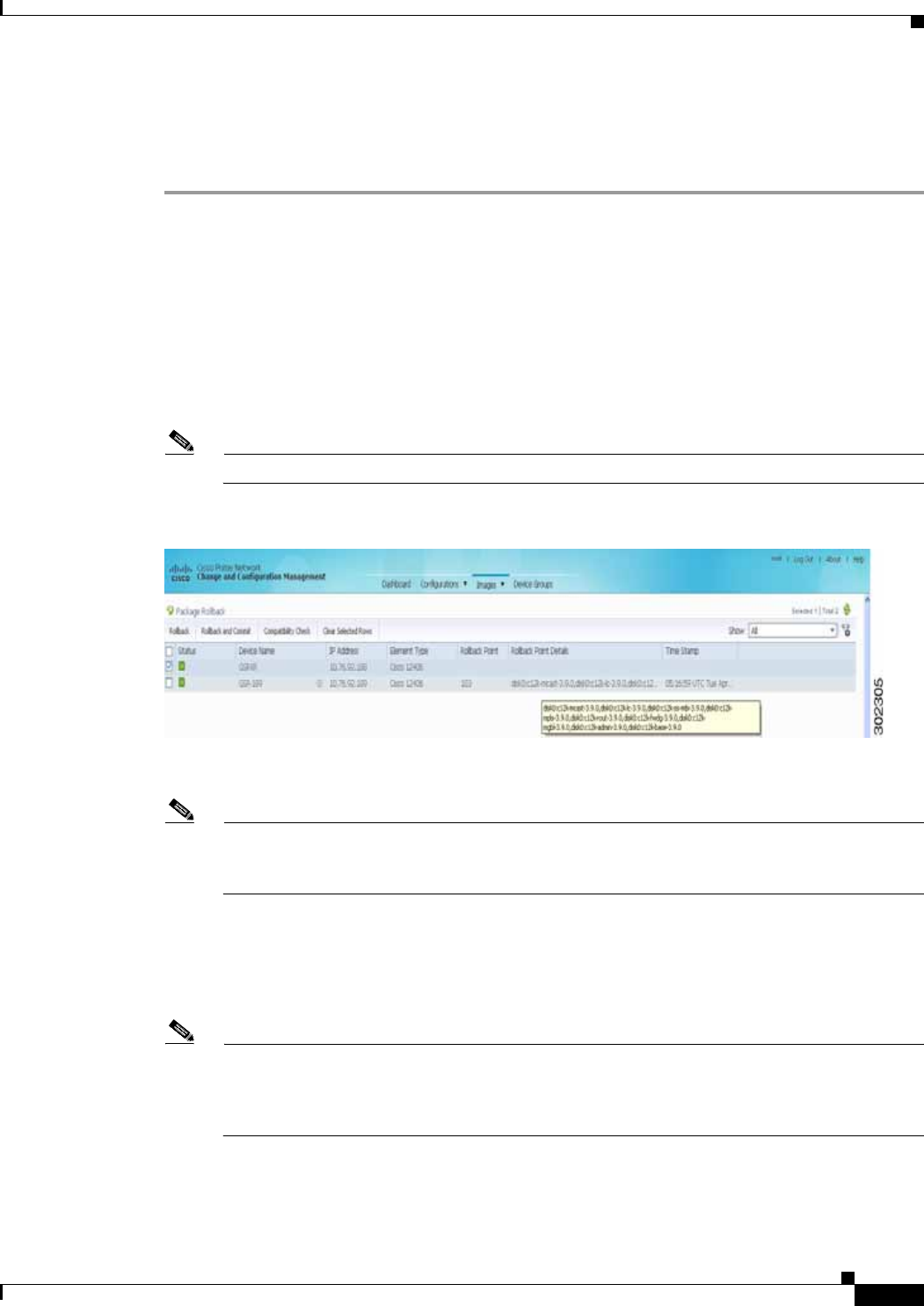
4-43
Cisco Prime Network 4.0 User Guide
OL-29343-01
Chapter 4 Device Configurations and Software Images Software Images
• Make sure you have the permissions to perform the rollback operation. You will not be allowed to
schedule a rollback job, if you do not have permissions.
To roll back a Cisco IOS XR package:
Step 1 Choose Images > Rollback. Prime Network displays all Cisco IOS XR devices. You can filter the
results by using the Quick Filter option.
Step 2 Choose the network elements. Prime Network populates the rollback points for the selected device
package.
Step 3 Choose a rollback ID from the Rollback ID drop-down list. The Rollback Point Details field lists the
packages that were active when that ID was created.
Step 4 To view all of the packages associated with the rollback point, place the mouse cursor on the Rollback
Point Details field; see Figure 4-9 for an example. To view the time stamp associated with the selected
rollback, see the value displayed in the Time Stamp field.
Note The date and time stamps are displayed according to the local time zone settings of the client.
Figure 4-9 Packages Rollback Page with Rollback Point Details
Step 5 Click OK to close the popup window.
Note If a package has been deleted from the repository, the rollback points of the package are still
displayed in the GUI. If you choose a rollback point for a deleted package, the rollback will fail.
The job results popup provides information explaining why it failed.
Step 6 (Optional) Click Compatibility Check in the table header to run a test of the rollback procedure on
the device. This will not change the real device configuration. (This is similar to using the Test Only
option in the activation process.)
Step 7 Click Rollback or Rollback and Commit.
Note We recommend that you do not commit package changes until the device runs with its
configuration for a period of time, until you are sure the change is appropriate. In that way, the
change is not yet persisted across device reloads. See Commit Cisco IOS XR Packages Across
Device Reloads, page 4-41.

4-44
Cisco Prime Network 4.0 User Guide OL-29343-01
Chapter 4 Device Configurations and Software Images
Software Images
Step 8 Enter the scheduling information.
Note The time you specify here to schedule the rollback job is the server time.
Step 9 Enter the e-mail ID(s) to which to send a notification after the scheduled rollback job is complete. For
two or more users, enter a comma-separated list of e-mail IDs. A notification e-mail is sent based on the
e-mail option specified in the Image Management Settings page.
Note Before you enter the e-mail ID(s), ensure that you have set up the SMTP host and SMTP port in
the Image Management Settings page (see Change Image Management Global Settings,
page 4-66). The e-mail ID(s) configured in the Image Management Settings page, if any, will be
displayed by default. You can modify the e-mail ID(s) if required.
Step 10 Click Rollback.
Clean Up the Repository
The repository is purged according to the settings described in NEIM Setup Tasks, page 4-7. When files
are removed from the repository, this does not affect files that are installed on the device. However,
deleting a package could cause a rollback point to become unexecutable. If a package or version of a
package that is associated with a specific rollback point is removed, it will no longer be possible to roll
back to that point. See Roll Back Cisco IOS XR Packages, page 4-42.
To delete images from the Prime Network image repository:
Step 1 Choose Images > Repository.
Step 2 Select the image you want to delete and click the Delete button (with red X) in the table header.
Step 3 To collectively delete all images in the repository, click the Delete All button in the table header. You
will see a prompt asking you to confirm whether or not to proceed with the operation.
Step 4 Click OK to confirm and image(s) available in the repository will be deleted.
These topics provide administrative information on CCM:
• Global Settings and Administration, page 4-61—How to use the Configuration Management
Settings page to specify when configurations should be collected, when they should be purged,
commands to exclude from comparisons, and other global settings.
• Change Image Management Global Settings, page 4-66—How to use the Image Management
Settings page to specify the default transfer protocol, staging and storing locations, and credentials
for accessing a vendor web site.
• Check the Processes, page 4-68—How CCM ensures communication security, authenticates and
authorizes users, where log files for debugging purposes are located, and so forth.
You should also make sure you have properly set up CCM by reading Configuration Management Setup
Tasks, page 4-5.

4-45
Cisco Prime Network 4.0 User Guide
OL-29343-01
Chapter 4 Device Configurations and Software Images Configuration Audit
Note In the Configuration Management and Image Management Settings pages, CCM does not support the
following special characters:
• For Password fields—>, <, ', /, \, !, :, ;, and "
• For all other fields—`, ~, @, #, $, %, ^, &, *, (, ), +, =, |, {, }, [, ], ', ?, >, <, /, \, !, :, ;, and "
Configuration Audit
Note Starting Prime Network 4.0, Configuration Audit is being replaced by Compliance Audit. However, if
you enabled the option to retain Configuration Audit during an upgrade procedure from Prime Network
3.11 (or earlier), the feature will still available from CCM. For more information on Compliance Audit,
see Compliance Audit, page 4-50.
CCM facilitates a configuration compliance mechanism, which enables auditing configurations on a
device against a specified configuration policy file (also called as a baseline or expected configuration).
Prime Network facilitates administering multiple configuration policy files through a Configuration
Audit Policy Manager. Each configuration policy is a set of CLI commands that define a desired baseline
or expected configuration. Configuration policies can also be configured using valid, Java-based regular
expressions. Table 4-4 provides examples of configuration policy CLIs.
Sample Configuration Policy
The following example shows a policy that performs audit for BGP configuration for a Cisco IOS router:
#BGP Configuration Audit
router bgp (.*)
neighbor (.*) remote-as (.*)
address-family ipv4
If you want an audit check for specific BGP AS or neighbor IP address, the above CLI can be changed
accordingly. For example:
router bgp 65000
neighbor (.*) remote-as 65001
address-family ipv4
Table 4-4 Configuration Policy CLI Examples
Policy Name Policy Description Policy CLI
SamplePolicy1 Sample policy for global
configuration auditing
spanning-tree mode rapid-pvst
SamplePolicy2 Sample policy for global regex and
first sub level cli matching audit
interface GigabitEthernet(.*)
port-type nni
SamplePolicy3 Sample policy for global regex,
first sub level cli matching, and
second sub level regex matching
router (.*)
address-family ipv4 unicast
network (.*)
SamplePolicy4 Sample policy for fixed cli
matching
interface GigabitEthernet3/4
address-family ipv4 unicast

4-46
Cisco Prime Network 4.0 User Guide OL-29343-01
Chapter 4 Device Configurations and Software Images
Configuration Audit
You can combine multiple different configurations into one policy. For example:
#BGP Configuration Audit
router bgp (.*)
neighbor (.*) remote-as (.*)
address-family ipv4
# Interface MEP check
interface GigabitEthernet(.*)
ethernet (.*)
mep domain UP (.*)
Configuration audit can be scheduled against multiple configuration files to obtain an audit report that
indicates the existence of configuration sequences stated in the baseline policy and any deviations from
the baseline.
You can define a configuration policy, select the devices that need to be audited against the policy, and
schedule the audit job to run immediately or at a later point in time. The audit job compares the CLI
commands (as part of the configuration policy) against the actual running configuration on the device to
identify the discrepancies.
You can view the status of all the scheduled configuration audit jobs in the Job Manager page. The
configuration audit results are in the form of a report indicating the discrepancies (missing configuration
commands on the device) in red and the matching commands in green.
Manage Configuration Policies
CCM allows you to create, modify, view, and delete configuration policies. Choose Configuration
Audit > Configuration Policies. The Configuration Policies page provides the list of existing policies.
You can search the configuration policies by CLI strings.
Create Configuration Policy
To create a configuration policy:
Step 1 In the Configuration Policies page, click Create.
Step 2 Provide the policy name and description.
Step 3 Enter the CLI commands to set up a baseline configuration for that policy. This can also be a valid,
Java-based regular expression. See Table 4-4 for sample configuration CLIs.
Step 4 Make sure you follow the guidelines while entering the CLI commands. Click Guidelines to view these
guidelines as shown in Figure 4-10.
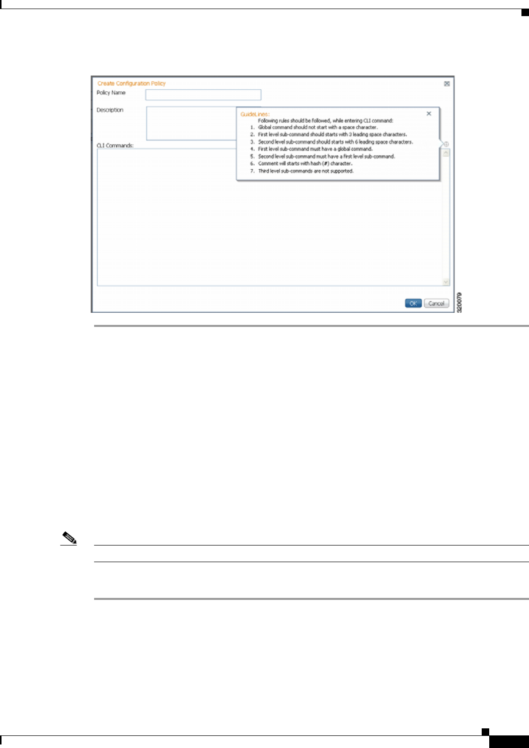
4-47
Cisco Prime Network 4.0 User Guide
OL-29343-01
Chapter 4 Device Configurations and Software Images Configuration Audit
Figure 4-10 Create Configuration Policy-Showing Guidelines
Edit, View, or Delete Configuration Policy
In the Configuration Policies page, you can also do the following:
• Select a policy and click Edit to modify the policy description and CLI commands. You cannot
modify the policy name. Keep in mind the policy guidelines while modifying the CLI commands.
• Select a policy and click View to view the policy name, description, and CLI commands.
• Select a policy or multiple policies and click Delete to delete the configuration policies. You cannot
delete a policy if it is part of a scheduled audit job.
Schedule Configuration Audit
You can schedule configuration audit jobs to run immediately or at a later point in time.
Note Only a maximum of 10 policies and 500 devices can be used for scheduling an audit job.
To schedule a configuration audit job:
Step 1 Choose Configuration Audit > Basic Audit. The Select Configuration Policies page lists the available
configuration policies. You can search the configuration policies by using CLI strings.
Step 2 Select the desired configuration policy from the available list and click Next.
Step 3 In the Select Devices page, select the devices that must be audited against the selected configuration
policy, and then click Next.

4-48
Cisco Prime Network 4.0 User Guide OL-29343-01
Chapter 4 Device Configurations and Software Images
Configuration Audit
Step 4 In the Schedule Audit page, provide a job name and the scheduling information for the configuration
audit job. You can choose to run the audit job immediately or at a later point in time. A popup with the
server time is available to assist you in setting up the time for scheduling the audit job.
Step 5 Click Audit. You will be redirected to the Configuration Audit Jobs page.
Note Once scheduled, you cannot edit the policies or devices that are part of the scheduled job.
View Configuration Audit Jobs and Audit Results
The Configuration Audit Jobs page (Configuration Audit > Configuration Audit Jobs) provides the
following details:
• Jobs—This table lists all configuration audit jobs submitted by the login user. The ‘root’ user can
view jobs submitted by other users, by selecting the username from the table header.
• History—For a selected job in the Jobs table, this table lists all the instances. You can select only
one job at a time to view the history details.
You can select a job and click View to view the associated devices and policies, and the schedule for the
selected audit job.
You can also use this page to suspend, resume, cancel, delete, or reschedule a job.
To view the configuration audit job details and the audit result:
Step 1 Click on the hyperlinked LastRun Result (Success/Partial Success/Failure) against a particular job in
the Jobs table.
The Configuration Audit Job Details dialog box displays the job details and the audit results for a device
and policy combination, as shown in Figure 4-11. The Job Results table includes the device audited,
policy against which the device was audited, audit status, and the running configuration version used for
the audit. A blue tick mark in the Status column indicates ‘Audit Pass’, and a red X indicates ‘Audit Fail’.
Click the hyperlinked policy name to view the configuration policy details, with updates if the policy has
been modified.
Note For Cisco Nexus devices, the VDC name is also displayed in the Device Name column.
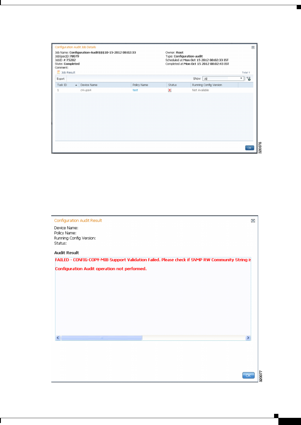
4-49
Cisco Prime Network 4.0 User Guide
OL-29343-01
Chapter 4 Device Configurations and Software Images Configuration Audit
Figure 4-11 Configuration Audit Job Details
Step 2 Click on the hyperlinked Status (Pass/Fail icon) in the Job Results table. Or, click the hyperlinked
Success or Failure hyperlink in the Result field of the History table. The Configuration Audit Result
dialog box displays the audit result with matching commands (for ‘Audit Pass’) and discrepancies or
missing commands (for ‘Audit Fail’) between the policy and the running configuration on the device.
See Figure 4-12 for an example of the Configuration Audit Result dialog box for an ‘Audit Fail’ scenario.
Figure 4-12 Configuration Audit Result - Audit Fail
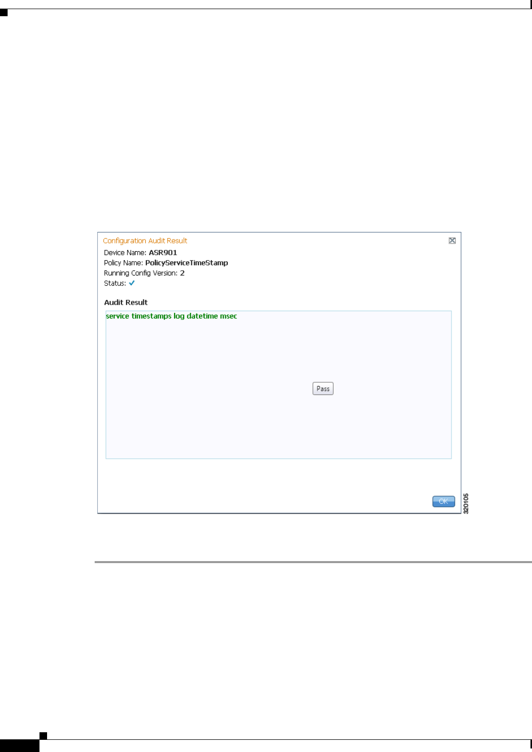
4-50
Cisco Prime Network 4.0 User Guide OL-29343-01
Chapter 4 Device Configurations and Software Images
Compliance Audit
The matching commands are displayed in green (see Figure 4-13), while the discrepancies are displayed
in red (see Figure 4-12). For a failed job, the Audit Result section also displays the reason why the audit
was not successful as shown in Figure 4-12. Some reasons for audit failure are:
• Failed to back up running configuration of the device
• Device not reachable
• Unable to download running configuration
• Device not under the scope of the user
• Policy is not available
• Invalid regular expression in the CLI
Figure 4-13 Configuration Audit Result - Audit Pass
Step 3 Click Export in the Job Results table to export the audit job results to a .csv file. You can view the job
details and audit results in the exported file.
Compliance Audit
The Compliance Audit feature (Cisco Change and Configuration Management > Compliance Audit)
ensures that existing device configurations comply to your deployment’s policies. It replaces the
Configuration Audit features that was provided in previous releases of Prime Network. This feature is
enabled by default.

4-51
Cisco Prime Network 4.0 User Guide
OL-29343-01
Chapter 4 Device Configurations and Software Images Compliance Audit
Using Compliance Audit, you can create policies that can contain multiple rules, and policies can be
grouped together to create a policy profile which can be run on a set of devices, called audit of devices.
There is no limit on the number of policies, profiles, rules, and conditions that you can create using
Compliance Audit. It can scale up to 35,000 devices.
When a device is detected to be not confirming to a determined policy, Compliance Manager calls it a
violation. Subsequently, if available, it also recommends a fix, as configured by the administrator. The
violation details are saved in DB Schema for your reference later.
In some scenarios, the fix is readily available as configured by the adminstrator and can be directly
applied, while in some others, it has to be carefully scrutinized by the administrator before it is run.
Automatic application of some of the fixes can be disabled since it may conflict with other policies and
configurations that may be specific to the device and the setup.
This section contains the following topics:
• User Authentication and Authorization, page 4-51
• Creating Policies and Profiles, and Running a Compliance Audit Job, page 4-52
User Authentication and Authorization
Compliance Audit uses the security methods employed by Prime Network. These are described in the
Cisco Prime Network 4.0 Administrator Guide.
Note If authentication fails, check the status of AVM 77 (XMP runtime DM) and Prime Network using Cisco
Prime Network Administration. Cisco Prime Network Administration displays AVM 77 only when Ciis
installed. For information on how to use Cisco Prime Network Administration, see the Cisco Prime
Network 4.0 Administrator Guide.
The GUI-based functions and required roles are listed in Table 4-5. The scope of your operation depends
on your role and scope.
Note If your role is Viewer, you cannot see Compliance Audit listed in CCM despite enabling it in the Registry
Controller.
The following table lists the permissions:
Table 4-5 Default Permission/Security Level Required to Use Compliance Audit
Task Administrator Configurator OperatorPlus Operator Viewer
Creating policies X X — — —
Creating policy profiles X X X X —
Executing audit job X X X X —
Viewing audit job results X (For all
users’ jobs) X (For jobs that the
specific user has
created)
X (For Operator
Plus jobs only) X (For
Operator
jobs only)
—

4-52
Cisco Prime Network 4.0 User Guide OL-29343-01
Chapter 4 Device Configurations and Software Images
Compliance Audit
Creating Policies and Profiles, and Running a Compliance Audit Job
Running an audit job the first time requires you to follow a specific workflow:
Creating a Policy
The first step in auditing devices is to create a policy (Compliance Audit > Compliance Policy). The
Compliance Policy page (Figure 4-14) appears.
Executing a Fix job
Note To execute a fix job, the
device-level role of the user
must be Configurator or
Administrator. The role of the
user for a device overrides the
role of a user on Prime
Network.
XX — ——
Viewing the fix job results X (For all
users’ jobs) X (For jobs that the
specific user has
created).
———
Table 4-5 Default Permission/Security Level Required to Use Compliance Audit (continued)
Task Administrator Configurator OperatorPlus Operator Viewer
Description See:
Step 1 Create a policy containing multiple rules Creating a Policy, page 4-52
Step 2 Group policies into policy profiles so you can apply them Creating a Policy Profile, page 4-57
Step 3 Run the policy against your specified devices Auditing Devices, page 4-58
Step 4 View the results and fix any violations Viewing the Results of an Audit Job and
Running Fixes for Violations, page 4-59
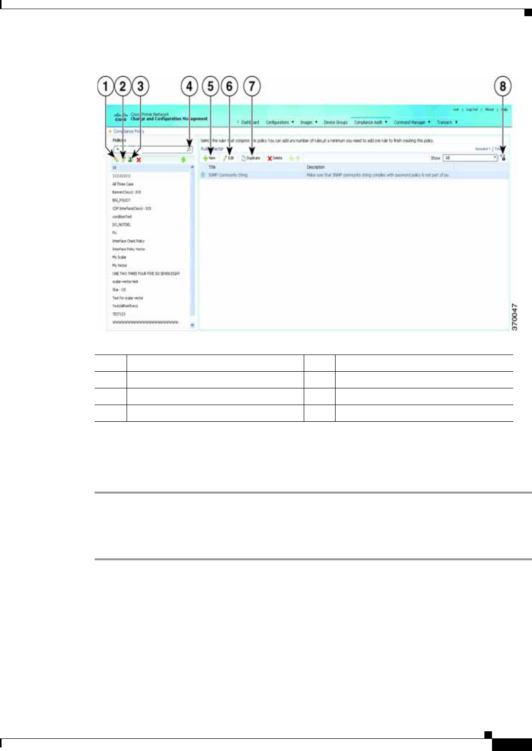
4-53
Cisco Prime Network 4.0 User Guide
OL-29343-01
Chapter 4 Device Configurations and Software Images Compliance Audit
Figure 4-14 Compliance Policy Page
The following steps explain the procedure:
You can either create a new policy or you can import an existing policy by clicking the Import icon. You
can export existing policies as XML files to your local drive.
Step 1 Click Create Compliance Policy icon and enter the policy details. The policy is listed in the left pane.
After you add a new policy, you must associate one or more rules to the policy.
Step 2 From the Rule Selector pane, click New Rule icon. For more information on creating a new rule, see
Creating a Rule.
Creating a Rule
For a policy to run against devices and generate violations, you must specify rules within the policy and
define the conditions and the relevant fixes for violations. Rules are platform-specific. Each policy must
contain at least one rule; however, there is no limitation on the number of rules you can define for a
policy. You can also duplicate an existing rule and add to a policy. Click the Duplicate button to clone
a rule. Follow the procedure below to create a rule and add the rule to a specific policy:
1Create Compliance Policy icon 5New Rule icon
2Edit Policy Description icon 6Edit Rule icon
3Import Policy as XML icon 7Duplicate Rule icon.
4Search field 8Filter icon

4-54
Cisco Prime Network 4.0 User Guide OL-29343-01
Chapter 4 Device Configurations and Software Images
Compliance Audit
Step 1 From the left navigation pane, select the policy to which you want to add rules.
Step 2 From the work area pane, click the Create Rule icon.
Step 3 Enter the following details. For sample rules, see Creating Rules—Samples, page 4-56.
Table 4-6 New Rule - Fields
Field Description
Rule Information
All information entered in this section is for your consumption. This information does not impact the conditions and the
subsequent violations.
Name Enter a name for the rule.
Description Enter a brief description
Impact Enter a brief note on the impact of the violation that the rule will generate.
Suggested Fix Enter a brief description of the fix that will help you decide to choose or to not choose the rule against
a specific policy. This description appears when you check the rule in the Rule Selector pane.
Platform Selection
Available Platforms Check the platforms on which the condition must be run. If you select Cisco Devices, all of Cisco
platforms specified in the list are included. The platforms checked in this section impacts the ignore
count of an audit job. For example, if you run a rule on all the devices within your scope, including
devices not selected in the Available Platforms pane, such devices are not audited and are marked
against Ignore count.
Rule Inputs
New Input Click the New icon to add inputs for the new rule. This field is optional. The input you create in this
pane reflects in the Policy Profile page. You must provide rule inputs for the rule you have selected.
For example, you can create an input to be IP Address. Any user who wants to run this rule can enter
an IP address specific to the rule and add it to a specific profile. Enter the following details:
• Title
• Identifier—Click the Generate button to generate an identifier based on the title. The identifier
is used in Block Start Expression, Conditions Match Criteria (value field), Action Details Tab -
Violation Message, Fix CLI (if action is Raise a Violation, and Violation Message Type is Define
Custom Violation Message for the Condition).
• Data Type—Choose a data type. The type of data you enter in the Parameter Substitution field
depends on your selection here.
• Input Required—Check the option, as required.

4-55
Cisco Prime Network 4.0 User Guide
OL-29343-01
Chapter 4 Device Configurations and Software Images Compliance Audit
Conditions and Actions—Conditions Details tab
Condition Scope
Details • Condition Scope—Choose the scope of the conditions from one of the below:
–
Configuration—Checks the complete running configuration
–
Previously Matched Blocks—Runs the conditions against blocks that have been defined in
previous conditions. To run the condition with this option, you must have checked Parse as
Block option in one of the previous conditions. You cannot select this option for the first
condition of a rule.
–
Device Properties—This checks against the device properties and not the running
configuration.
• Device Property—This option is enabled only if you selected Device Properties option in the
Condition Scope option.
Block Options
Parse as Blocks Checking this option enables you to run conditions on specific blocks (as defined in this section) in
running configuration files. This option is enabled only if you selected Configuration in the
Condition Scope option.
Block Start Expression This field is mandatory if Parse as Blocks option is enabled. This must be a regular expression. Rule
Inputs can be used here.
Block End Expression This field is optional. By default, blocks end when the top-level or a sub-level command begins. If
you prefer to break the block earlier, enter the value as a regular expression.
Rule Pass Criteria Check the option, as required. If you select:
• All Sub Blocks—The rule is marked a success only if all the blocks fulfill the specified
condition.
• Any Sub Block—The rule is marked a success even if one of the sub blocks fulfill the condition.
• Raise One Violation for Each Failing Instance—If you check this option, the violation count
specified in the Job view increases by as many number of violations as the condition encounters
in each block.
Condition Match Criteria
Operator Choose an option based on the value you will enter in the subsequent field.
Value The value must be a regular expression. This variable can be grepped for use in the subsequent
conditions. It follows the convention of condition <number.value number> such as, <2.1> <2.2>...
This numerical identifier can be used from the next condition as input parameter for Operator
selected in the previous field.
Rule Pass Criteria Check the option, as required. If you select:
• All Sub Blocks—The rule is marked a success only if all the blocks fulfill the specified
condition.
• Any Sub Block—The rule is marked a success even if one of the sub blocks fulfill the condition.
• Raise One Violation for Each Failing Instance—If you check this option, the violation count
specified in the Job view increases by as many number of violations as the condition encounters
in each block.
Table 4-6 New Rule - Fields (continued)
Field Description

4-56
Cisco Prime Network 4.0 User Guide OL-29343-01
Chapter 4 Device Configurations and Software Images
Compliance Audit
After you complete adding rules to the policy, a profile must be created. For more information, see
Creating a Policy Profile.
Creating Rules—Samples
This section explains three scenarios in which rules can be created.
Problem This policy checks if at least one of the pre-defined DNS servers are configured on device.
The following condition checks if either IP name-server 1.2.3.4 or IP name-server 2.3.4.5 is
configured on the device, and raises a violation if neither of them are configured.
Solution The following settings have to be made in the appropriate sections.
New Conditions and Actions—Action Details tab (applicable for both Match Action and Does Not Match Action
Select Action Select one of the following actions that Compliance Audit must perform upon detecting a violation:
• Continue—If the condition is met or not met, the rule continues to run based on the condition
number specified in the field. If a condition number is not specified, the rule skips to the next
immediate condition.
• Raise a Violation—Raises a violation and stops further execution of rule.
• Do Not Raise a Violation—Does not raise a violation; stops further execution of rule.
Condition Number Specify the condition number to which the rule must continue with in case the condition is met or is
not met. You cannot specify a condition number that is lesser than or equal to the current condition
number. This field is enabled only if you selected the option Continue from the Select Action field.
Violation Severity Specify a severity that Compliance Audit must flag if a violation is detected. This field is enabled
only if you selected one of the options, Raise a Violation from the Select Action field.
Violation Message
Type Select a message type. If you determine a violation as not fixable (or requiring manual intervention),
select the Generate Default Violation Message During Audit option. To enter a fix for a violation,
select the option Define Custom Violation Message for the Condition.
Violation Message Enter a violation message that is displayed in the Job View window. select the option Define Custom
Violation Message for the Condition.
Fix CLI Enter a relevant CLI fix if the device does not meet the condition specified. select the option Define
Custom Violation Message for the Condition.
Do not enter config t and its exit commands.
Note exit command is allowed at main and sub-level commands.
Table 4-6 New Rule - Fields (continued)
Field Description
Field Value
Configuration Scope Configuration
Operator Matches the expression
Value ip name-server (1.2.3.4|2.3.4.5)$
Match Action Do not raise a violation and exit this rule

4-57
Cisco Prime Network 4.0 User Guide
OL-29343-01
Chapter 4 Device Configurations and Software Images Compliance Audit
Problem This policy checks if at least two NTP servers are configured on the device for NTP server
redundancy.
The following condition checks if the command ntp server appears at least twice.
Solution The following settings have to be made in the appropriate sections.
Problem This policy checks if the device is not configured with any prohibited community strings or
community strings that must be avoided for SNMP.
This condition checks if either snmp-server community public or snmp-server community private is
configured on the device. If configured, Compliance Audit raises a violation. Note that <1> in the
violation text is replaced with the actual community string configured on the device, at the runtime. In
this example, <1> indicates first captured group in the current condition.
Solution The following settings have to be made in the appropriate sections.
Creating a Policy Profile
After you have created policies, create a policy profile that will contain a set of policies. Go to
Compliance Audit > Policy Profile. The Policy Profile page (Figure 4-15) appears.
Does Not Match Action Raise a violation and exit this rule
Violation Text DNS Server must be configured as either 1.2.3.4 or 2.3.4.5.
Field Value
Field Value
Configuration Scope Configuration
Operator Matches the expression
Value (ntp server.*\n){2,}
Match Action Continue
Does Not Match Action Raise a violation and exit this rule
Violation Text At least two NTP servers must be configured.
Field Value
Configuration Scope Configuration
Operator Matches the expression
Value snmp-server community (public|private)
Match Action Raise a violation and exit this rule.
Does Not Match Action Continue
Violation Text Community string <1> configured.
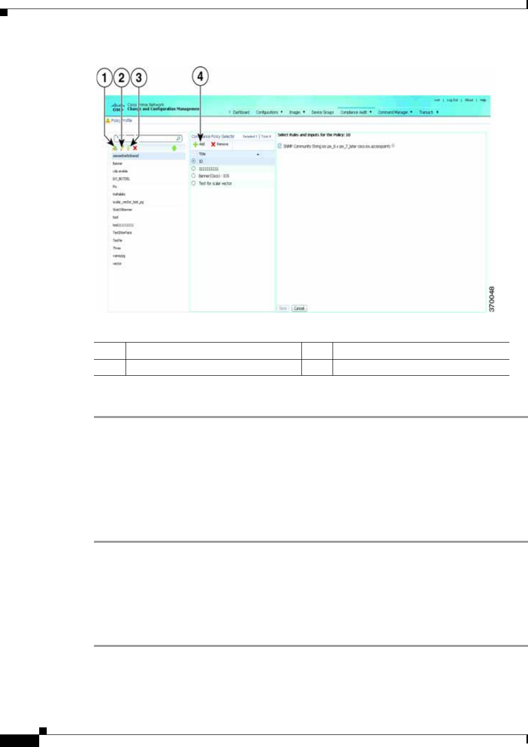
4-58
Cisco Prime Network 4.0 User Guide OL-29343-01
Chapter 4 Device Configurations and Software Images
Compliance Audit
Figure 4-15 Policy Profile Page
Follow the procedure below to create a new policy profile:
Step 1 From the left navigation pane, click the Create New Policy Profile icon. Enter name and description of
the policy profile.
Step 2 Choose a policy profile from the left navigation pane. From the Compliance Policy Selector pane, click
the Add Compliance Policy icon. The list of policies appear. Choose the required policies.
Step 3 After you choose the policies, select the rules within the selected which you want to audit against. Later,
if applicable, enter values for rule inputs. The option to enter rule inputs is available only if you entered
input parameters when you created a new rule.
Policy Profiles are created and an audit job can be run.
Auditing Devices
After you create a policy profile, you must choose the devices on which it has to be run. After you choose
the devices and schedule an audit, a job with the name of the policy profile name is created. This name
defines this job, and can be scheduled periodically. This job name is editable.
Step 1 After you have created the profiles, click the Run Compliance Audit icon.
The Select Devices window appears.
Step 2 Select the devices which you wish to audit. Click Next.
1Create Policy Profile icon 3Run Compliance Audit icon
2Edit Policy Profile Description icon 4Add Compliance Policy icon

4-59
Cisco Prime Network 4.0 User Guide
OL-29343-01
Chapter 4 Device Configurations and Software Images Compliance Audit
Step 3 The Schedule Audit page appears. Enter the schedule details. Against Choose Configuration option,
choose the configuration that you want to be applied:
• Use Latest Archived Configuration—If you choose this option, the latest Backup Configuration
available in NCCM is used. If the backup configuration is not available, the device is not audited
and is marked against non-audited devices.
• Use Current Device Configuration—If you choose this option, Prime Network polls for the latest
configuration from the device and then performs the audit.
Step 4 Click Audit. An audit job is scheduled. You can view the status of an audit job from the Jobs page.
Viewing the Results of an Audit Job and Running Fixes for Violations
The status of scheduled jobs appears on the Jobs page (Compliance Audit > Jobs). All audits are logged
by Prime Network as jobs.
From this page, you can view the violation details and can also apply a fix. After a job is created, you
can set the following preferences for the job:
• Suspend—Can be applied only on jobs that are scheduled for future. You cannot suspend a job that
is running.
• Resume—Can be applied only on jobs that have been suspended.
• Reschedule—Using this option, you can reschedule a job that has been scheduled for a different
time. Choose a job, and click Reschedule. The Compliance Audit Job Rescheduler window opens.
Set your preferences. The following options are available against Choose Configuration option:
–
Use Latest Archived Configuration—If you choose this option, the latest Backup Configuration
available in NCCM is used.
–
Use Current Device Configuration—If you choose this option, Prime Network polls for the
latest configuration from the device and performs the audit.
Note You might be prompted to enter your device access credentials. This option is enabled if, from the Prime
Network Administration > Global Settings > Security Settings > User Account Settings >
Execution of Configuration Operations, you checked the option Ask for user credentials when
running configuration operations. This is an enhanced security measure to restrict access to devices.
• Cancel—Using this option, you can cancel a scheduled job.
• View—This option is enabled only for jobs that in Completed state. Using this option, you can view
the details of a job, the associated policies and devices.
• Delete—This option deletes a job that has been scheduled. This deletes the listing from the GUI.
You cannot delete a job that is running.
All jobs that are completed are listed in the jobs page. The job is flagged a success only if all the devices
audited confirm to the policies specified in the profile. The result, otherwise, is displayed as Failure. The
job is called a partial success if job contains a mix of both audited and non-audited devices, with the
compliance status of audited devices being a success.
You can view the details of the job by clicking the hyperlinked result displayed against each job. When
you click the result, the Compliance Job Audit Details window displays the violation details. The
Compliance Audit Violation Details window displays the following details:

4-60
Cisco Prime Network 4.0 User Guide OL-29343-01
Chapter 4 Device Configurations and Software Images
Compliance Audit
You can view the status of a fix job after the job completes. Click the hyperlinked status to view the
results of the fix job.
Table 4-7 Compliance Audit Violation Details- Fields
Field Description
Job Details and Violations Summary
Audited/Non-Audited
Devices This displays the number of audited and non-audited devices. For more details on devices, click
the hyperlinked count of audited and non-audited devices. Non-audited devices include the count
of the following.
–
The devices that were within the scope of the user while scheduling the job, but has since
changed. At the time job ran, these devices were not within the scope of the user.
–
The devices that were down or were not reachable when the job ran.
–
CPT device not in IOS mode. These devices are not audited because they do not contain
running configuration, which is required for Compliance Manager.
–
Third Party Devices.
–
Device not in sync with with Compliance server—that is, the device element type is not
available in the Compliance server.
–
Devices of which backup running configuration cannot be fetched from CCM.
Selected Rules Number of rules selected in a policy at the time the policy profile was created. This may be subset
of the total number of rules defined for the policy.
Compliance State Displays Pass or Fail. All rules in policy for all devices must confirm for the state to display Pass.
Violation Count This lists the number of distinct violations (for a particular policy, for the number of devices) that
were observed in each job. For example, if a particular policy is violated in 100 devices, the
violation count is only 1.
Instance Count Summation of the violation count for all the device. For example, if a particular policy is violated
in 100 devices, the instance count is 100.
Highest Severity The highest severity of the various rules comprising the policy. The highest (as decided at the time
of creating rules) is shown. This overrides the lower severity items.
Ignore Count This is the count of rules ignored due to devices falling outside the scope of platforms defined
against the rule.
Violations by Device
Violations by Device This window displays the violations at a device level. Select the devices for which require the fix
CLI to be applied. Only the devices for which a fix CLI is available can be selected. Click Next.
Preview Fix Commands
Preview Fix Commands Select a violation to view the respective CLI for the devices. If two or more options are selected,
the CLI is appended. To schedule a fix job, click Next.
Schedule
Schedule Schedule to the fix job. The details of the fix job can be viewed from Compliance Audit > Jobs.
The job type is Compliance-Fix

4-61
Cisco Prime Network 4.0 User Guide
OL-29343-01
Chapter 4 Device Configurations and Software Images Global Settings and Administration
Global Settings and Administration
This topic contains the following sections:
• Change Configuration Managemennt Global Settings, page 4-61
• Change Image Management Global Settings, page 4-66
• Check the Processes, page 4-68
• Manage Jobs, page 4-68
• User Authentication and Authorization, page 4-69
Change Configuration Managemennt Global Settings
To open the Configurations global settings page, choose Configurations > Settings. Table 4-8 lists all
of the global settings you can configure for Configuration Management.
The backup settings you enter here do not affect the manual backups you can perform by choosing
Configurations > Backup. The backups you perform from that page and the backups you configure on
this Settings page are completely independent of each other.
Note Make sure that the configuration change detection schedule does not conflict with purging, since both
processes are database-intensive.
Table 4-8 Configuration Archive Global Settings
Field Description
Export Settings
Server Name DNS-resolvable server name.
Note CCM supports export servers with IPv4 or IPv6 address.
Location The full pathname of the directory to which Prime Network should copy the file on the server
specified in the Server Name field.
Username The login username that Prime Network should use when connecting to the server specified in the
Server Name field.
Password The login password that Prime Network should use when connecting to the server specified in the
Server Name field.
Export Protocol Default export protocol that Prime Network should use when exporting configuration files to another
server. The choices are FTP and SFTP. The default is FTP.
You can override this protocol while scheduling an export job, if required.
Archive Purge Settings
Minimum Versions to
Retain Minimum number of versions of each configuration that should be retained in the archive (default is
2).
Maximum Versions to
Retain Maximum number of versions of each configuration that Prime Network should retain (default is 5).
The oldest configuration is purged when the maximum number is reached. Configurations marked
“do not purge” are not included when calculating this number.

4-62
Cisco Prime Network 4.0 User Guide OL-29343-01
Chapter 4 Device Configurations and Software Images
Global Settings and Administration
Minimum Age
to Purge Age (in days) at which configurations should be purged (between 5-360).
Configuration Change Purge Settings
Purge Change Logs
after The age in days at which configuration change notifications (Change Logs) that are sent by devices
should be purged. The default is 30 days and the range is 5-360.
Global Settings
Transport Protocol Default transport protocol that Prime Network should use when copying configuration files to and
from a device. The options are TFTP, SFTP/SCP, and FTP. The default is TFTP. Note the following:
• The TFTP source interface on the devices must be able to reach the unit. Otherwise, the
configuration management jobs that require TFTP may fail.
• To use SFTP/SCP for config transfers from a device to a unit, you need to ensure that an SSH
server is configured and running on the device, such that the device acts as a server and the unit
as a client during the transfer. For Cisco IOS XR devices, you need to configure the device with
K9 security (k9sec) enabled images such that the SSH server is up and running on the device.
Enable Periodic
Config Backup Detect ongoing configuration changes by performing a periodic collection of device information. Use
this method if configurations change frequently and those changes are not important to you. CM
compares the timestamp for the last configuration change on the archived version with the timestamp
on the newer version. If they are different, CM backs the new file to the archive immediately. By
default, this is not enabled.
You can set up an interval in the range of 1-100 hours. Default value is 72 hours.
Note This CM collection is independent of the Prime Network inventory collection.
Enable Periodic Sync
for Out of Sync
Devices (72 Hours)
(For Cisco IOS only) Enables automatic synchronization of the out-of-sync devices on a periodic
basis. Prime Network adds a device to the list of out-of-sync devices whenever the latest version of
the startup configuration is not in sync with the latest version of the running configuration file on the
device.
Periodic Export Options
Enable Periodic
Config Export Allows CM to export archived configurations periodically to the export server. You can set up an
interval in the range of 1-100 hours to export the archived configurations. The default value for export
interval is 24 hours. You can also specify the start time for the periodic export operation.
If there are no configuration changes i.e. if the archived configuration is available in the export server,
choose one of the following options to indicate how the export job should be performed:
• Export configuration file will all configuration—Overwrite the existing configuration on the
export server.
• Do not export configuration file—Skip configuration export.
• Export configuration file with reference to previous configuration file—Create a configuration
file with only a reference to the file having the actual configuration.
Refer to Configuration Export File Type for Device Families, page 4-66, to know more about the type
of configuration files exported for different devices.
Table 4-8 Configuration Archive Global Settings (continued)
Field Description

4-63
Cisco Prime Network 4.0 User Guide
OL-29343-01
Chapter 4 Device Configurations and Software Images Global Settings and Administration
Enable Initial Config
Syncup Allows CM to fetch the configuration files from the network devices and archive it whenever a new
device is added to Prime Network. If this setting is enabled:
• CM performs the configuration file fetch operation whenever the Prime Network gateway is
restarted.
• The Disable Initial Config Syncup on Restart check box is enabled by default to prevent network
device performance issues on subsequent Prime Network gateway restarts.
To preserve this setting such that CM fetches the configuration files from network devices on Prime
Network gateway restarts, you must uncheck the Disable Initial Config Syncup on Restart check box
after enabling the Enable Initial Config Syncup option.
Note The “sync up” described here pertains to making sure the archive correctly reflects the
network device configurations. This is different from the CM Synchronize operation, where
devices are checked to make sure their running and startup configurations are the same.
This “sync up” is required in order for Prime Network to populate the Configuration Sync Status
dashlet (on the dashboard).
Disable Initial Config
Syncup on Restart Check the check box to set Enable Initial Config Syncup to its default
setting (not enabled) if Prime Network restarts.
Enable
Event-Triggered
Config Archive
Detect ongoing configuration changes by monitoring device configuration change notifications. This
setting also controls whether Prime Network populates the Configuration Changes in the Last Week
and the Most Recent Configuration Changes dashlets (on the dashboard).
Use this method if you consider every configuration file change to be significant. When a notification
is received, CM backs up the new running configuration file to the archive using one of the following
methods.
Note If you are using event-triggered archiving, you should also make sure that exclude commands
are properly configured. Exclude commands are commands that Prime Network ignores
when comparing configurations, and they are controlled from the Settings page. Using this
mechanism eliminates unnecessary file backups to the archive.
Sync archive on each
configuration change Upon receiving a change notification from a device, immediately
backs up the device configuration file to the archive.
Sync archives with changed
configurations every ___
hours and ___ minutes
Upon receiving a change notification from a device, queue the
changes and backs up the device configuration files according to the
specified schedule.
Table 4-8 Configuration Archive Global Settings (continued)
Field Description

4-64
Cisco Prime Network 4.0 User Guide OL-29343-01
Chapter 4 Device Configurations and Software Images
Global Settings and Administration
Device Access
Credentials For enhanced security, and to prevent unauthorized access to devices, you might be asked to enter
device credentials. This option is enabled if, from the Prime Network Administration > Global
Settings > Security Settings > User Account Settings > Execution of Configuration Operations,
you checked the option Ask for user credentials when running configuration operations. By
default, the device credentials field is populated with the default VNE credentials. You must change
the credentials to the device credentials before you save the settings. System jobs will fail, if the
credentials entered are incorrect. If you checked the option Ask for user credentials when running
configuration operations from Prime Network Administration, and did not change the settings from
the Settings page after making the change, all system jobs that are scheduled to run will fail.
If the option Ask for user credentials when running configuration operations (from Prime
Network Administration) is not enabled, the default VNE credentials are used. Also, if device
credentials are entered in the Settings page, and the option Ask for user credentials when running
configuration operations is not enabled from Prime Network Administration GUI, the device
credentials you have entered in the Settings page are ignored and the default VNE credentials are
used.
Restore Mode Settings
Restore Mode Mode for restoring configuration files to a device:
• Overwrite—Prime Network overwrites the existing configuration on the device with the file you
selected from the archive. Check the Use Merge on Failure check box to restore configuration
files in merge mode, if overwrite mode fails.
• Merge—Prime Network merges the existing running or startup configuration on the device with
the configuration present in the version you selected from the archive.
E-mail Settings
SMTP Host SMTP server to use for sending e-mail notifications on the status of configuration management jobs
to users. If an SMTP host is configured in the Image Management Settings page, the same value will
be displayed here by default. You can modify it, if required.
E-mail Id(s) E-mail addresses of users to send a notification to after the scheduled job is complete. For two or
more users, enter a comma-separated list of e-mail IDs. For example:
xyz@cisco.com,abc@cisco.com
The e-mail IDs configured here will appear by default while scheduling the configuration
management jobs. However, you can add/modify the e-mail IDs then.
SMTP Port SMTP port ID to connect to the host server. The default port is 25.
Email Option Choose from the following options to specify when you want to send an e-mail notification for CM
jobs:
• All—To send a notification e-mail irrespective of the job result.
• Failure—To send a notification e-mail only when the job has failed.
• No Mail—Do not send a notification e-mail on the job status.
The selected option will appear by default while scheduling CM jobs. However, you can modify the
option then.
Table 4-8 Configuration Archive Global Settings (continued)
Field Description

4-65
Cisco Prime Network 4.0 User Guide
OL-29343-01
Chapter 4 Device Configurations and Software Images Global Settings and Administration
Notes on Exclude Commands
Exclude commands are inherited; in other words, if three exclude commands are specified for Cisco
routers, all devices is any of the Cisco router families will exclude those three commands when
comparing configuration files.
Caution Exclude commands configured for a device family (such as Cisco 7200 Routers) will be applied to all
device types in that family (Cisco 7201, Cisco 7204, Cisco 7204VXR, and so forth).
When you are working in the Exclude Commands GUI, your current selection will be highlighted in
green. All exclude commands applied to that selection will be listed below the device selector. When
Prime Network compares the router configuration files, it will exclude all of the commands listed in the
Device Commands field. If a series is selected (example, Cisco 7200 Series), the commands listed in the
Series Commands field will be excluded and so on.
The following procedure describes how to configure exclude commands.
Step 1 Choose Configurations > Settings.
Step 2 In the Exclude Commands area, navigate and choose one of the following (your selection is highlighted
in green):
• A device category
• A device series
• A device type
Step 3 Enter a comma-separated list of commands you want to exclude when comparing configuration files for
that device category, series, or type. You can also edit an existing list of commands.
Your entries change to red until they are saved, and all affected device types, series, or categories are
indicated in bold font.
Step 4 If you want a device type to ignore the parent commands (that is, the series and category commands),
check the Ignore Above check box.
Step 5 Click Save to save your changes.
Exclude Commands
(Device Selector) Selected devices to which the exclude commands should be applied (that is, the commands will not
be considered when comparing any type of device configuration files). The current selection is
highlighted in green. All exclude commands applied to that selection will be listed below the device
selector. See Notes on Exclude Commands, page 4-65.
Category Commands Comma-separated list of commands to be excluded when comparing device configurations for any
devices in this category (for example, all Cisco routers)
Series Commands Comma-separated list of commands to be excluded when comparing device configurations for any
devices in this series (for example, all Cisco 7200 series routers)
Device Commands Comma-separated list of commands to be excluded when comparing device configurations for any
devices of this same device type (for example, all Cisco 7201 routers)
Table 4-8 Configuration Archive Global Settings (continued)
Field Description

4-66
Cisco Prime Network 4.0 User Guide OL-29343-01
Chapter 4 Device Configurations and Software Images
Global Settings and Administration
Configuration Export File Type for Device Families
The following table provides the types of configuration files exported for different types of devices.
Change Image Management Global Settings
To open the Image Management global settings page, choose Images > Settings. Table 4-9 lists all of
the global settings you can configure for Image Management.
Device Type Configuration File Exported Condition(s)
Cisco IOS device Only the latest running
configuration If there is no running version, the latest
startup configuration is exported
Cisco IOS XR device Latest running and startup
configuration None
Cisco ASR 5000 series
devices Latest running configuration If there is no running version, boot
configuration is NOT exported
Cisco 7600 device with
ACE card Latest running configuration If there is no running version, the latest
startup configuration is exported
Cisco Nexus device Latest running configuration If there is no running version, the latest
startup configuration is exported
Table 4-9 Image Management Global Settings
Field Description
Transfer Protocol Default transfer protocol to use when copying images to and from a device. This setting can be
overridden when creating a distribution job (for example, if you know a device does not support the
default protocol). FTP and TFTP are unsecured.
• The TFTP source interface on the devices must be able to reach the unit. Otherwise, the image
management jobs that require TFTP may fail.
• To use SFTP/SCP for image transfers from a device to a unit, you need to ensure that an SSH server
is configured and running on the device, such that the device acts as a server and the unit as a client
during the transfer. For Cisco IOS XR devices, you need to configure the device with K9 security
(k9sec) enabled images such that the SSH server is up and running on the device. (Cisco IOS XR
devices use SFTP, and Cisco IOS devices use SCP).
Flash Properties In case of insufficient memory, use the Clear Flash option (under Flash Properties). This deletes any
one file (other than the running image) and recovers the disk space occupied by the file. This procedure
is repeated until adequate space is available in the selected flash.
Warm Upgrade If Warm Upgrade is checked, a Cisco IOS image can read in and decompress another Cisco IOS image
and transfer control to this new image. This functionality reduces the downtime of a device during
planned Cisco IOS software upgrades or downgrades. This can be overridden when creating the job.
Note You can perform a warm upgrade only on Cisco IOS devices 12.3(2)T or later, such as 12.4T,
15.0, 15.1T, and for ISR 800/1800/2800/3800 series and 1900/2900/3900 series.

4-67
Cisco Prime Network 4.0 User Guide
OL-29343-01
Chapter 4 Device Configurations and Software Images Global Settings and Administration
File Locations Full pathname of directories where images are stored when they are being imported into the
Prime Network image repository, or when they are being transferred out of the repository to devices.
New directories must be empty and have the proper permissions (read, write, and execute permissions
for users).
The entries must be full pathnames. In the following default locations, PRIME_NETWORK_HOME
is the Prime Network installation directory, normally /export/home/network-user; where network-user
is the operating system user for the Prime Network application and an example of network-user is
network39.
Staging Directory Location where images from the Prime Network image repository are placed
before transferring them out to devices. The default is
PRIME_NETWORK_HOME/NCCMComponents/NEIM/staging/.
Storing Directory Location where images from an outside source are placed before importing them
into the Prime Network image repository (from Cisco.com, from existing
devices, or from another file system). The default is
PRIME_NETWORK_HOME/NCCMComponents/NEIM/images/.
External Server
Details Details about external server from which images can be imported into repository.
Server Name IP address of the external server (IPv4 or IPv6 addresses supported).
Image Location Path where the image is located on the server.
User Name Username to access the external server.
Password Password to access the external server.
SSH Port SSH port ID to connect to the server.
E-mail Settings Settings for automatic e-mail notifications about the status of jobs.
SMTP Host SMTP server to use for sending e-mail notifications on the status of image
management jobs to users. If an SMTP host is configured in the Configuration
Management Settings page, the same value will be displayed here by default. You
can modify it, if required.
E-mail Id(s) E-mail address of the user to send a notification to after the scheduled job is
complete. For two or more users, enter a comma-separated list of e-mail
addresses. For example:
xyz@cisco.com,abc@cisco.com
The e-mail IDs configured here will appear by default while scheduling the
image management jobs. However, you can add/modify the e-mail IDs then.
SMTP Port SMTP port ID to connect to the host server. The default port is 25.
Email Option Controls when e-mail notifications for NEIM jobs are sent (can be overridden
when creating the job):
• All—Send a notification irrespective of the job result.
• Failure—Send a notification e-mail only when the job has failed.
• No Mail—Do not send a notification e-mail on the job status.
Table 4-9 Image Management Global Settings (continued)
Field Description

4-68
Cisco Prime Network 4.0 User Guide OL-29343-01
Chapter 4 Device Configurations and Software Images
Global Settings and Administration
Check the Processes
CCM runs on AVM 77. To check, start, stop, or restart the process, use the following commands:
dmctl status
dmctl start
dmctl stop
dmctl restart
Manage Jobs
Prime Network redirects you to the Jobs page whenever a CM or image management job is scheduled to
run immediately. When a job is created, Cisco Prime Network assigns it a job specification ID and
attaches a time stamp, indicating when the job was created. Only the job creator and users with
Administrator privileges can change the job settings.
Prime Network also facilitates automatic e-mail notification of the status of the CM and NEIM jobs upon
completion based on the e-mail option you set up in the configuration and image management settings.
The notification is sent to a list of e-mail IDs configured either in the settings page or while scheduling
the job.
Keeps these items in mind when managing jobs:
• All jobs are scheduled based on the server time.
• If you choose two or more jobs and click Reschedule, the option defaults to ‘Start as Soon as
Possible.’ To view the original time and then reschedule, choose only one job and click Reschedule.
• Job properties cannot be edited; you must delete the old job and create a new one.
• Jobs are persisted even if the gateway server is restarted.
• Only the job creators and users with Administrator and Configurator privileges can perform the
actions provided on the Jobs page (suspend, resume, reschedule, cancel, delete, refresh).
• Configuration and image management jobs fail under the following conditions:
–
If the device is not under the scope of the user to perform the config or image operation.
–
If the user is not authorized to perform the config or image operation.
–
For Cisco CPT devices, if the device is not in Cisco IOS mode.
• Running jobs cannot be suspended or cancelled; you must let them complete.
• System-generated jobs cannot be modified. To change the settings, go to Settings > Global Settings
> Period Export Options, and modify the options accordingly.
Proxy Settings Details about proxy server to use when importing images from Cisco.com
HTTP Proxy HTTP proxy server to use for downloading images from Cisco.com.
Port Port address to use for downloading images from Cisco.com.
Vendor Credentials Usernames and passwords that can be used to download images from Cisco.com. (See the procedure
described in Check the Processes, page 4-68)
Table 4-9 Image Management Global Settings (continued)
Field Description

4-69
Cisco Prime Network 4.0 User Guide
OL-29343-01
Chapter 4 Device Configurations and Software Images Global Settings and Administration
• Cancel stops all future instances of a job. To stop a job and resume it later, use Suspend and Resume
• To view the history of a job, choose a job and view the history from the History tab at the bottom of
the page. You cannot view history of multiple jobs at the same time; choose only one job at a time.
Messages that can be used for debugging are saved in
PRIME_NETWORK_HOME/XMP_Platform/logs/JobManager.log.
User Authentication and Authorization
User Authentication and Authorization
CCM uses the security methods employed by Prime Network. These are described in the Cisco Prime
Network 4.0 Administrator Guide
Note If authentication fails, check the status of AVM 77 (XMP runtime DM) and Prime Network using Cisco
Prime Network Administration. Cisco Prime Network Administration displays AVM 77 only when CCM
is installed. For information on how to use Cisco Prime Network Administration, see the Cisco Prime
Network 4.0 Administrator Guide.
The GUI-based functions and required roles are listed in Table 4-10. Note that these functions do not
perform any actions on devices.
Table 4-10 GUI-Based Access Roles Required to Use CCM
Function Viewer Operator OperatorPlus Configurator Administrator
Dashboard
Access top families X X X X X
Configuration Management
Delete files from archive 1XX
Add, change, delete archive file
labels1XX
Add change, delete archive file
comments1XX
Export files from archive1XX
Image Management
View images in repository X X X X X
Add images to repository X X
Delete images from repository X X
Global Tasks
View jobs X X X X X
Administer jobs (suspend,
delete, and so forth) XX
Change settings X X
Compliance Audit
Creating policies X X — — —

4-70
Cisco Prime Network 4.0 User Guide OL-29343-01
Chapter 4 Device Configurations and Software Images
Global Settings and Administration
Table 4-11 lists all of the CCM functions that are that filtered to only show devices in the device scope
of a user, along with the role required to perform any functions on those devices.
Creating policy profiles X X X X —
Executing audit job X X X X —
Viewing audit job results X
(user’s
jobs)
X (user’s
jobs) X
(OperatorPlus
jobs)
X
(Configurator
jobs)
—
Executing a Fix job
Note To execute a fix job, the
device-level role of the
user must be
Configurator or
Administrator. The role
of the user for a device
overrides the role of a
user on Prime Network.
XX — — —
Viewing the fix job results X X — — —
Configuration Audit
Define configuration policies X X
Schedule configuration audit X X
View configuration audit jobs
and audit results XXX
Managing Device Groups
Create device groups X X X X X
Edit device group details X X
Delete device groups X X
1. Configuration files are filtered according to the device scope of a user.
Table 4-10 GUI-Based Access Roles Required to Use CCM (continued)
Function Viewer Operator OperatorPlus Configurator Administrator
Table 4-11 Device Scope-Based Roles Required to Use CCM
Function Viewer Operator Operator Plus Configurator Administrator
Dashboard
Access configuration sync
status1XX X X X
Access configuration changes in
the last week1XX X X X
Access most recent configuration
changes1XX X X X
Configuration Management
View files in archive1XX X X X

4-71
Cisco Prime Network 4.0 User Guide
OL-29343-01
Chapter 4 Device Configurations and Software Images Global Settings and Administration
For information on how Prime Network performs user authentication and authorization, including an
explanation of user access roles and device scopes, see the Cisco Prime Network 4.0 Administrator
Guide.
Compare files in archive X X X X X
Synchronize configurations X X
Back up (copy) files from
devices to archive XXX
Restore files from archive to
devices XX
Edit configuration files before
restoring them to devices XX
View configuration change logs X X X X X
Image Management
Distribute images X X
Activate and deactivate images X X
Commit image changes X X
Rollback images X X
Managing Device Groups
Create device groups X X
Edit device group details X X
Delete device groups X X
Compliance Audit
Creating policies X X — — —
Creating policy profiles X X X X —
Executing audit job X X X X —
Viewing audit job results X X X X —
Executing a Fix job — — — X X
Viewing the fix job results X X — — —
Configuration Audit
Define configuration policies X X
Schedule configuration audit X X
View configuration audit jobs
and audit results XXX
1. Although users can view configuration files for devices in their scopes, the actions they can perform on those configuration
files are controlled by the GUI-based access roles in Table 4-10.
Table 4-11 Device Scope-Based Roles Required to Use CCM (continued)
Function Viewer Operator Operator Plus Configurator Administrator

4-72
Cisco Prime Network 4.0 User Guide OL-29343-01
Chapter 4 Device Configurations and Software Images
Global Settings and Administration

CHAPTER
5-1
Cisco Prime Network 4.0 User Guide
OL-29343-01
5
Working with Prime Network Vision Maps
The topological map is the main tool used by Cisco Prime Network Vision (Prime Network Vision) to
display the links and relationships between the network elements and aggregations. The following topics
describe how to work with the topological maps displayed in the content pane of the Prime Network
Vision window:
• User Roles Required for Working with Prime Network Vision Maps, page 5-2
• Opening and Closing Maps, page 5-5
• Creating and Deleting Maps, page 5-6
• Adding and Removing NEs from Maps, page 5-9
• Managing Maps, page 5-11
• Finding NEs, Services, and Links, and Elements Affected by Tickets, page 5-15
• Working with Aggregations, page 5-16
• Working with Overlays, page 5-21
• Filtering Links in a Map, page 5-25
• Opening the CPU Usage Graph, page 5-27
• Communicating with Devices Using Ping and Telnet, page 5-28
You can also perform the following functions from the map and list views if they are configured for your
client:
• Launch external applications or tools, such as an SSH client.
• Launch available scripts and commands, depending on the NE device type, OS, supported
technologies, and so forth. Those commands are documented throughout this guide (for example,
Setting Up Devices and Validating Device Information, page 1-4). This also includes commands you
create using Command Manager and Command Builder. A list of scripts is provided in Cisco Prime
Network 4.0 Supported VNEs - Addendum.

5-2
Cisco Prime Network 4.0 User Guide OL-29343-01
Chapter 5 Working with Prime Network Vision Maps
User Roles Required for Working with Prime Network Vision Maps
User Roles Required for Working with Prime Network Vision
Maps
This topic identifies the roles that are required to work with Prime Network Vision maps. Prime Network
determines whether you are authorized to perform a task as follows:
• For GUI-based tasks (tasks that do not affect elements), authorization is based on the default
permission that is assigned to your user account.
• For element-based tasks (tasks that do affect elements), authorization is based on the default
permission that is assigned to your account. That is, whether the element is in one of your assigned
scopes and whether you meet the minimum security level for that scope.
For more information on user authorization, see the Cisco Prime Network 4.0 Administrator Guide.
The following tables identify the tasks that you can perform:
• Table 5-1 identifies the tasks that you can perform if a selected element is not in one of your
assigned scopes.
• Table 5-2 identifies the tasks that you can perform if a selected element is in one of your assigned
scopes.
By default, users with the Administrator role have access to all managed elements. To change the
Administrator user scope, see the topic on device scopes in the Cisco Prime Network 4.0 Administrator
Guide.
Table 5-1 Default Permission/Security Level Required for Working with Prime Network Vision
Maps - Element Not in User’s Scope
Task Viewer Operator OperatorPlus Configurator Administrator
Map-Related Tasks
Apply a background
image ——— X X
Create maps——XXX
Define a map layout X X X X X
Delete maps — — X X X
Open mapsXXXXX
Preview and print maps X X X X X
Rename maps——XXX
Save as a new map — — X X X
Save as an image X X X X X
Save map appearance — — X X X
Select viewing options X X X X X
Use Overview window X X X X X
View mapsXXXXX

5-3
Cisco Prime Network 4.0 User Guide
OL-29343-01
Chapter 5 Working with Prime Network Vision Maps User Roles Required for Working with Prime Network Vision Maps
Element-Related Tasks
Add elements to a map — — X X X
Remove elements from
a map ——XXX
Resize elements in a
map XXXXX
Aggregation-Related Tasks
Group and ungroup
aggregations ——XXX
Rename aggregations X X X X X
View aggregation
thumbnails XXXXX
Finding Items in Maps
Find affected elements — — — — X
Find an element or
service XXXXX
Find and select a link in
a map1XXXXX
Link-Related Task
Filter links X X X X X
Overlay-Related Tasks
Apply an overlay X X X X X
Hide or view an overlay X X X X X
Remove an overlay X X X X X
Other Tasks
Open the CPU Usage
Graph ————X
Use Ping and Telnet to
communicate with
elements
————X
1. This applies to links within the selected context, and not links identified as network links.
Table 5-1 Default Permission/Security Level Required for Working with Prime Network Vision
Maps - Element Not in User’s Scope (continued)
Task Viewer Operator OperatorPlus Configurator Administrator

5-4
Cisco Prime Network 4.0 User Guide OL-29343-01
Chapter 5 Working with Prime Network Vision Maps
User Roles Required for Working with Prime Network Vision Maps
Table 5-2 Default Permission/Security Level Required for Working with Prime Network Vision
Maps - Element in User’s Scope
Task Viewer Operator OperatorPlus Configurator Administrator
Map-Related Tasks
Apply a background
image ——— X X
Create maps——XXX
Define a map layout X X X X X
Delete maps — — X X X
Open mapsXXXXX
Preview and print maps X X X X X
Rename maps——XXX
Save as a new map — — X X X
Save as an image X X X X X
Save map appearance — — X X X
Select viewing options X X X X X
Use Overview window X X X X X
View mapsXXXXX
Element-Related Tasks
Add elements to a map — — X X X
Remove elements from
a map ——XXX
Resize elements in a
map XXXXX
Aggregation-Related Tasks
Group and ungroup
aggregations ——XXX
Rename aggregations X X X X X
View aggregation
thumbnails XXXXX
Finding Items in Maps
Find affected elements X X X X X
Find an element or
service XXXXX
Find and select a link in
a map1XXXXX

5-5
Cisco Prime Network 4.0 User Guide
OL-29343-01
Chapter 5 Working with Prime Network Vision Maps Opening and Closing Maps
Opening and Closing Maps
Whenever you open a map, the network information is automatically refreshed. For example, if a device
was up the last time that the map was saved and closed, and then the device is moved to maintenance,
the next time you open the map the management status of the device is updated accordingly and the
device displays a maintenance status.
When you first log in, Prime Network Vision lists the maps you recently viewed but did not close when
you exited the session. You can also open other maps by choosing File > Open, which displays the Open
Map dialog.
By default, you can view and work on a maximum of five maps at any given time (per client instance)
in the Prime Network Vision window. To change this default setting, contact your Cisco account
representative. To create a new map or select a new map, close the required number of maps.
You can save maps as images or print them, if desired.
To close a map, choose File > Close. Prime Network Vision saves basic map information whether or not
you manually save the map. This default information includes device and link additions, device and link
removals, aggregations, and disaggregations. If you made any changes that will not be saved, Prime
Network Vision prompts you to save the map.
Link-Related Task
Filter links X X X X X
Overlay-Related Tasks
Apply an overlay X X X X X
Hide or view an overlay X X X X X
Remove an overlay X X X X X
Other Tasks
Open the CPU Usage
Graph ——XXX
Use Ping and Telnet to
communicate with
devices
——— X X
1. This applies to links within the selected context, and not links identified as network links.
Table 5-2 Default Permission/Security Level Required for Working with Prime Network Vision
Maps - Element in User’s Scope (continued)
Task Viewer Operator OperatorPlus Configurator Administrator
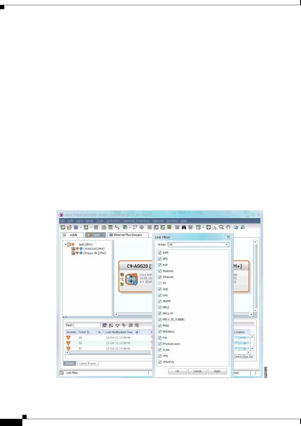
5-6
Cisco Prime Network 4.0 User Guide OL-29343-01
Chapter 5 Working with Prime Network Vision Maps
Creating and Deleting Maps
Creating and Deleting Maps
You can create maps that cover specific network segments, customer networks, or any other mix of
network elements required. Network maps provide a graphic display of active faults and alarms, and
serve as access points for activating services. When you create a map, it is saved in the database and
made available to other users if they have sufficient access and security privileges. When you delete a
map, it is removed from the database. See these topics for more information:
• Creating New Maps, page 5-6
• Deleting Maps from the Database, page 5-8
Creating New Maps
To create a new map, choose File > New Map in the main menu. The following figures give examples
of how you can create and manipulate maps. To add NEs to maps, see Adding and Removing NEs from
Maps, page 5-9.
Link Filters
Link filters let you choose the links in which you are interested, and then build a map that only displays
NEs using those link types. Examples are physical links, data links, MPLS, VLANs, and so forth. When
you open the New Map dialog, click the Advanced button and choose the types you want to display.
Figure 5-1 Map with Link Filter
To create a map with link filters, see Figure 5-13.
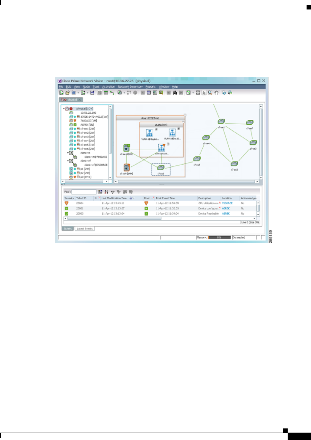
5-7
Cisco Prime Network 4.0 User Guide
OL-29343-01
Chapter 5 Working with Prime Network Vision Maps Creating and Deleting Maps
Aggregations
Aggregations are user-defined groups of elements. An aggregation can contain network elements,
services, other aggregations, and so forth. Figure 5-2 shows an example of an aggregation.
Figure 5-2 Map with Aggregation (Thumbnail View)
When you delete an aggregation, the member devices are not deleted from Prime Network; only the
aggregation definition is deleted. To create an aggregation, see Working with Aggregations, page 5-16.
Overlays
Overlays isolate the parts of a network that are being used by a specific service, such as an ethernet service
or network clock. Figure 5-3 shows an example of an Ethernet Service overlay, where the ethernet link is
using the service.
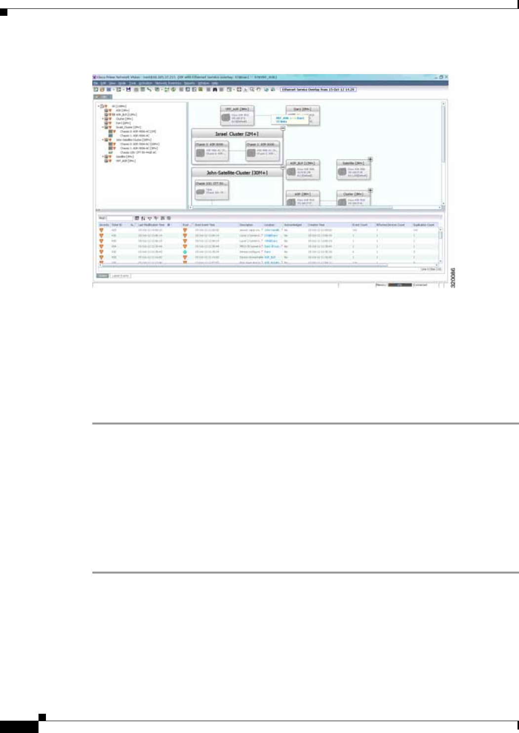
5-8
Cisco Prime Network 4.0 User Guide OL-29343-01
Chapter 5 Working with Prime Network Vision Maps
Creating and Deleting Maps
Figure 5-3 Map with Overlay
To create an overlay, see Working with Overlays, page 5-21.
Deleting Maps from the Database
If another client is using a map that you are deleting, Prime Network Vision displays a message to those
clients advising them that the map is being closed and deleted from the database.
To delete a map from Prime Network Vision and the Prime Network Vision database:
Step 1 Open the Open Map dialog by choosing File > Open.
Step 2 In the Open Map dialog box, complete the following steps:
a. Select the map you want to delete.
b. In the toolbar, click Delete Map. A confirmation message is displayed.
c. Click Yes. The selected map is deleted from the Open Map dialog box, the Prime Network Vision
window, and the database. If the map is open when you click Yes, a message is displayed, stating
that the map will be closed.
d. Click OK to acknowledge that the map can be closed.
e. Click Cancel to close the Open Map dialog box.
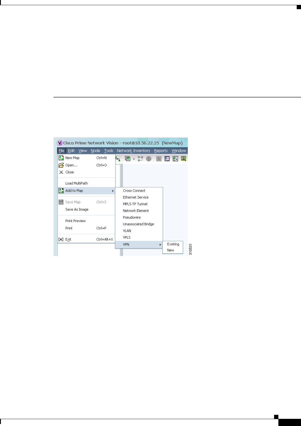
5-9
Cisco Prime Network 4.0 User Guide
OL-29343-01
Chapter 5 Working with Prime Network Vision Maps Adding and Removing NEs from Maps
Adding and Removing NEs from Maps
When you add an element to a map, the map is automatically saved in the Prime Network Vision database
If the element you want to add is outside of your scope, it is not displayed if you enter a search string.
You can display all NEs by selecting Show All in Step 2, but devices outside your scope will be
displayed with a lock icon.
To add an element to a map:
Step 1 Choose File > Add to Map > element.
Figure 5-4 shows the type of elements you can add to maps.
Figure 5-4 Available Elements to Add to Maps
If you choose to add a new VPN, the Create VPN dialog box is displayed. For information on creating
a VPN, see Creating a VPN, page 18-21
In all other instances, the Add element to map dialog box is displayed, as shown in Figure 5-5.
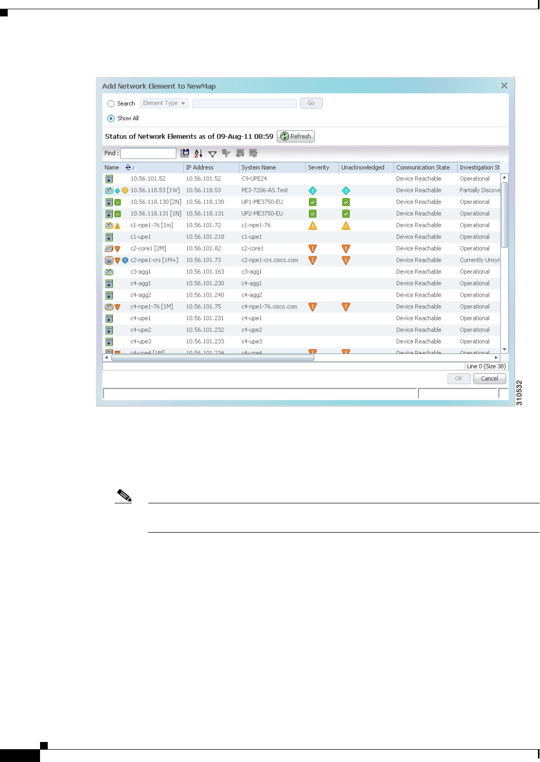
5-10
Cisco Prime Network 4.0 User Guide OL-29343-01
Chapter 5 Working with Prime Network Vision Maps
Adding and Removing NEs from Maps
Figure 5-5 Add Element Dialog Box
Step 2 In the Add element dialog box, do one of the following:
If you are working with a very large number of network elements, keep these items in mind:
• Search for the elements you want to add to the map. For example, you can search Ethernet Services
by the system name, NEs element type, pseudowires by their role, and so forth.
Note If you are working with a large number of NEs, using the search filter Otherwise, it may take
some time for all of the NEs to be listed.
• To view all available elements, choose Show All.
The available elements are displayed in the Add element dialog box in table format. The dialog box also
displays the date and time at which the list was generated. To update the list, click Refresh.
If a network element is not included in your scope, it is displayed with the locked device icon.
Step 3 In the Add element dialog box, select the elements that you want to add. You can select and add multiple
elements by pressing Ctrl while selecting individual network elements or by pressing Ctrl + Shift to
select a group of elements.

5-11
Cisco Prime Network 4.0 User Guide
OL-29343-01
Chapter 5 Working with Prime Network Vision Maps Managing Maps
Step 4 Click OK. If you selected a large number of elements (for example, more than 25 VLANs or VPLS
instances), the action may take a while to complete.
The NEs are added to the map and are displayed in the navigation pane and content area. In addition,
any associated tickets are displayed in the ticket pane.
Removing Elements from a Map
When you delete an element or aggregation from a map, it is removed from the map in the database, but
the elements are still managed by Prime Network Vision.
Note Based on the security level and access permissions assigned, this option might not be available to all
users.
To remove a network element or aggregation from a map:
Step 1 In the navigation pane or map, select the element or aggregation that you want to delete.
Step 2 Right-click to display the right-click menu and choose Remove from Map. The selected element or
aggregation is removed from the map.
The element is removed from the map in the database, but is still managed by Prime Network Vision and
can be added again.
Managing Maps
The following topics describe how to manage maps in Prime Network Vision:
• Selecting Map Viewing Options, page 5-12
• Applying a Background Image, page 5-12
• Using the Overview Window, page 5-14
• Saving Maps, page 5-15

5-12
Cisco Prime Network 4.0 User Guide OL-29343-01
Chapter 5 Working with Prime Network Vision Maps
Managing Maps
Selecting Map Viewing Options
Table 5-3 describes the tools that you can use to view and manipulate maps in the Prime Network Vision
map pane.
Applying a Background Image
Prime Network Vision allows you to apply a background image to the map view. You can also choose
the same background image or different images for other subordinate windows, such as detailed views
of aggregations, VLANs, and VPNs.
The supported file formats are GIF, JPG/JPEG, and PNG.
Note Background images are not supported in thumbnail views.
To apply a background image to a map:
Step 1 Navigate to the required map in Prime Network Vision. The map can reside at the top level or in a
subordinate window.
Step 2 Right-click the map background and choose Set Map Background.
The Manage Map Background dialog box is displayed, as shown in Figure 5-6.
Table 5-3 Prime Network Vision Map Viewing Options
Button Name Function
Layout Map Defines how a topology should be displayed: Circular,
hierarchical, orthogonal, or symmetric. The default is circular.
When you choose a map layout, the elements align accordingly,
using animation by default. Related characteristics, such as the
speed of the animation and whether an expanded node causes
sibling nodes to move aside, are also configured by settings in the
registry.
Fit in Window Fits an entire aggregation or map in the map pane.
Normal Selection
Mode Activates normal selection mode.
Zoom Selection Mode Activates the zoom selection mode, which enables you to select an
area in the map pane to enlarge by clicking and dragging the zoom
mode cursor.
Pan Mode Activates the pan mode, which enables you to move around in the
map pane by clicking and dragging the pan mode cursor.

5-13
Cisco Prime Network 4.0 User Guide
OL-29343-01
Chapter 5 Working with Prime Network Vision Maps Managing Maps
Figure 5-6 Manage Map Background Dialog Box
Step 3 Enter the required information as described in Table 5-4.
Step 4 Click OK. The current map background is updated as specified.
Step 5 To retain the background image for subsequent logins, do one of the following:
• Click Save in the toolbar.
• Choose File > Save.
Table 5-4 Manage Map Background Options
Field Description
Select Image Applies the selected image to the current map background:
1. Choose Select Image.
2. Click Browse.
3. In the Open dialog box, select the desired image and click OK.
The name of the selected image is displayed in the Manage Map
Background dialog box.
4. Click OK. The selected image is displayed as the map
background.
Use Image From Upper Level Indicates whether the selected subordinate map should use the same
image as the parent map or a different image:
• To use the same image that is used by the parent map, choose
Use Image from Upper Level. The name of the image used by
the parent map is displayed by default.
• To use a different image than that used by the parent map,
choose Select Image and complete the steps described for that
option.
Remove Image Removes the current image from the map background.
To remove an image from the current map, click Remove Image.
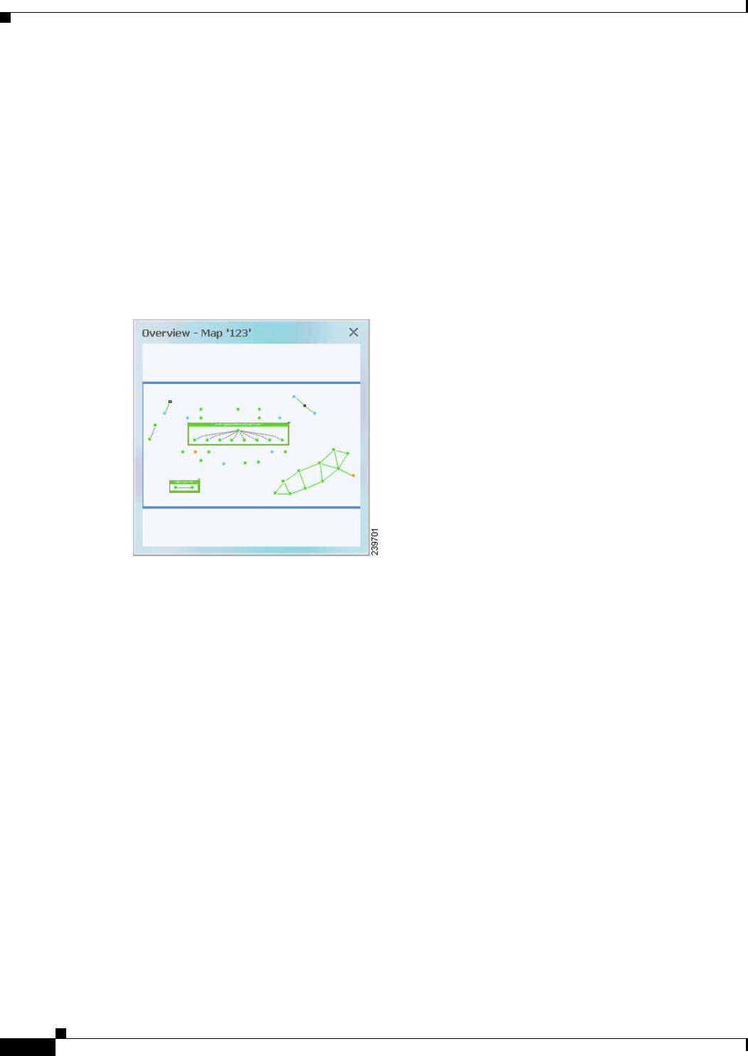
5-14
Cisco Prime Network 4.0 User Guide OL-29343-01
Chapter 5 Working with Prime Network Vision Maps
Managing Maps
Using the Overview Window
The Prime Network Vision Overview window enables you to display the entire network map or any part
of the map that you require in the map pane. The Overview window also enables you to see all the
changes and alarms taking place in the network.
To open the network Overview window do either of the following:
• Click Overview in the main toolbar.
• Choose View > Overview from the main menu.
Figure 5-7 shows an example of the Overview window.
Figure 5-7 Overview Window
The Overview window can contain the following components:
• Dot—Indicates an element. The dot color indicates the severity of an associated alarm.
• Line—Indicates a link. The line color indicates the severity of an associated alarm.
• Blue rectangle—Indicates the selection area. The area within the rectangle is displayed in the map
pane. Handles on the corners enable you to resize the selection area.
• Pan mode cursor—Displayed within the selection area. Use this cursor to move the selection area,
and thereby view different elements in the map pane.
• Zoom mode cursor—Displayed outside the selection area. Use this cursor to define a new selection
area or to zoom in on an existing selection area.
Click the upper right corner to close the Overview window.

5-15
Cisco Prime Network 4.0 User Guide
OL-29343-01
Chapter 5 Working with Prime Network Vision Maps Finding NEs, Services, and Links, and Elements Affected by Tickets
Saving Maps
By default, Prime Network Vision saves basic map information whether or not you manually save the
map. This default information includes element additions and removals, link additions and removals,
aggregations, and disaggregations. However, you must use the Save Map option if you want to retain the
following information in the database:
• Device location on the map
• Thumbnails
• Icon size
To save these changes, click Save Map Appearance in the main toolbar, then click OK. The map is
saved as an image in the directory you specified.
Finding NEs, Services, and Links, and Elements Affected by
Tickets
The following topics describe how to find network elements, services, links, or elements affected by a
ticket in Prime Network Vision maps.
Table 5-5 Aggregation Thumbnail Options
If you want to find... Do this...
An NE or service From the Prime Network Vision main menu, choose Edit > Find in Map.
Enter an element or service (such as a VPN or VLAN) by entering any part of
its name or device IP address. If you want your search to include aggregations,
check the Search all map levels check box.
A link From the Links view, right-click the link and choose Find Link in Map. The
link is highlighted in the map pane. If two or more lines represent the same
link (such as a VRF link), you can choose the appropriate one.
If more than one edge device contains the same link in the same map or
context, all related edge devices are selected in the map.
Which NEs are
affected by a ticket In the ticket pane, right-click the required ticket and choose Find Affected
Elements. If only one element is affected, the affected element is selected in
the navigation pane and the content area; if a link is affected, the affected link
is selected in the links view.
If two or more elements are affected, the affected elements are displayed in
the Affected Elements window.
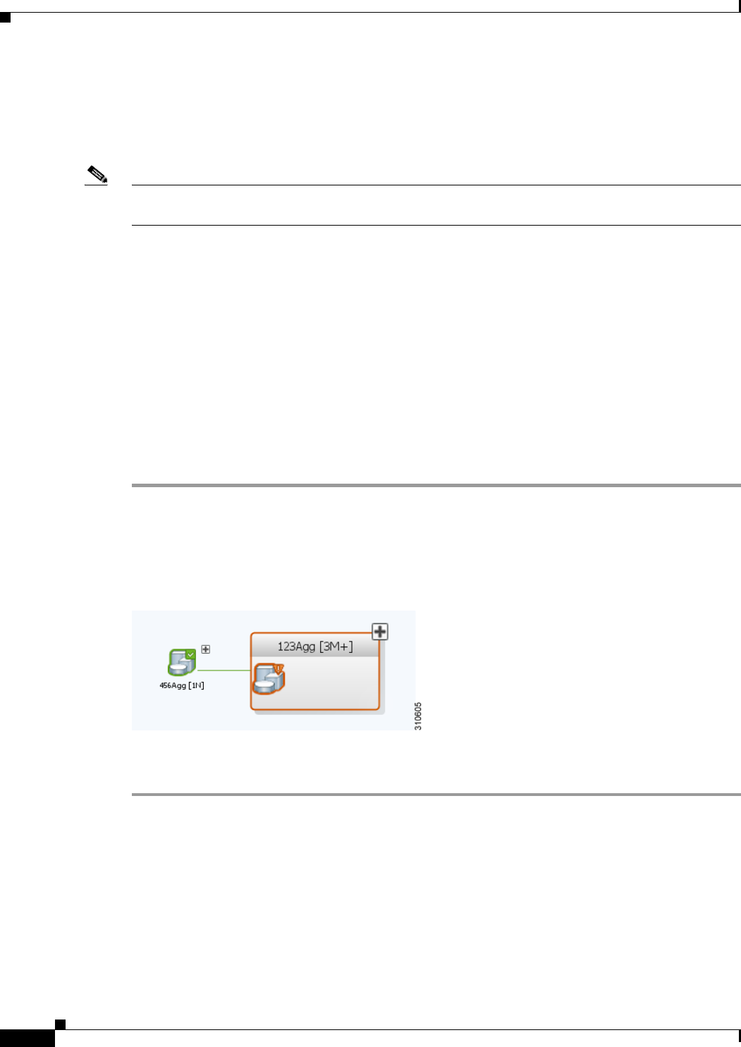
5-16
Cisco Prime Network 4.0 User Guide OL-29343-01
Chapter 5 Working with Prime Network Vision Maps
Working with Aggregations
Working with Aggregations
Prime Network Vision enables you to group network elements and display them as an aggregation.
Aggregations can contain network elements, services, other aggregations, and so forth.
Note You cannot aggregate service entities that exist within a service. For example, you cannot aggregate
VRFs that exist within a VLAN.
For more information on working with aggregations, see the following topics:
• Grouping Network Elements into Aggregations, page 5-16
• Adding Elements to an Existing Aggregation, page 5-18
• Viewing an Aggregation Thumbnail, page 5-16
• Ungrouping Aggregations, page 5-19
• Viewing Multi-Chassis Devices, page 5-19
Grouping Network Elements into Aggregations
To aggregate network elements:
Step 1 Select the network elements. To select multiple items, press Ctrl.
Step 2 Aggregate the network elements by choosing Node > Aggregate.
Step 3 In the Aggregation dialog box, enter a unique name for the aggregation and click OK. The aggregation
is displayed in the navigation pane and the map pane. Aggregations are displayed as a single entity with
the Aggregation icon and a plus sign, as in the following examples:
The aggregation icon changes color according to the alarm severity. For more information about severity
colors, see Alarm Indicators, page 2-12.
Viewing an Aggregation Thumbnail
You can view a thumbnail of a selected aggregation in the map pane, including all aggregated elements
and any nested aggregations.
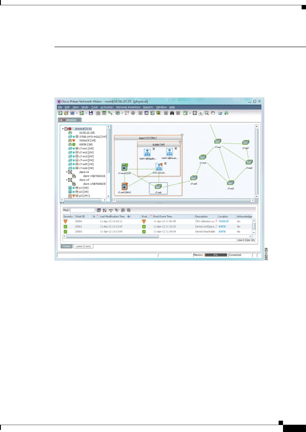
5-17
Cisco Prime Network 4.0 User Guide
OL-29343-01
Chapter 5 Working with Prime Network Vision Maps Working with Aggregations
To display an aggregation thumbnail:
Step 1 Select the existing aggregation in the map pane.
Step 2 Open the thumbnail by right-clicking the aggregation, and choosing Show Thumbnail.
The thumbnail is displayed in the map pane as shown in Figure 5-8.
Figure 5-8 Aggregation Thumbnail
When a thumbnail is opened, neighboring nodes are moved aside by default to allow room for the
thumbnail to expand. Similarly, when a thumbnail is closed, the neighboring nodes usually return to their
original locations. This behavior of the neighboring nodes when a thumbnail is opened and closed is
configured in the registry, and can be disabled, if required.
A dashed gray border around an icon indicates that the element resides within a thumbnail and not at the
current map level.

5-18
Cisco Prime Network 4.0 User Guide OL-29343-01
Chapter 5 Working with Prime Network Vision Maps
Working with Aggregations
Table 5-6 describes the options available when working with aggregation thumbnails.
Step 3 To close the aggregation thumbnail, right-click the thumbnail frame and choose Show As Aggregation.
Adding Elements to an Existing Aggregation
You can add elements to an existing aggregation at any time. When adding elements to an aggregation,
keep in mind that certain restrictions exist. For example, you cannot add an EVC to a VLAN.
To add elements to an existing aggregation:
Step 1 Select the existing aggregation in the map pane.
Step 2 Open the thumbnail by right-clicking the aggregation, and choosing Show Thumbnail.
Step 3 Double-click the thumbnail frame to view the aggregation at the map level.
Step 4 Click Add to Map to add the required element to the aggregation.
Step 5 Return to the map by double-clicking the map background.
Table 5-6 Aggregation Thumbnail Options
If you want to... Do this...
Rearrange the icons in the thumbnail Click and drag the required icons to arrange them as
needed.
Resize an icon Select the icon to be resized, and then either click and
drag the gray border or right-click a selected icon and
choose Resize.
The right-click Resize option allows you to resize
multiple selected icons at the same time.
Resize the thumbnail frame Click and drag one or more icons. If you drag an icon
beyond the thumbnail frame, Prime Network Vision
adjusts the thumbnail size automatically.
View a nested aggregation Click the nested aggregation plus sign.
View only the aggregation in the map pane Double-click the thumbnail frame.
View the next higher level in the map pane Double-click the current map background.
Zoom in or out in the thumbnail Position your mouse cursor in the map and use the mouse
scroll wheel to zoom in or out.

5-19
Cisco Prime Network 4.0 User Guide
OL-29343-01
Chapter 5 Working with Prime Network Vision Maps Working with Aggregations
Ungrouping Aggregations
Aggregations can be ungrouped. If the aggregation that you ungroup contains nested aggregations, the
nested aggregations move up one level, and the original aggregation is removed.
If an element in the aggregation that you ungroup also exists at the parent level, the element is
represented only once after the aggregation is ungrouped. As a result, no elements are represented twice
at the same level.
To ungroup an aggregation:
Step 1 Select the required aggregation in Prime Network Vision.
Step 2 Ungroup the node by selecting the aggregation in the map pane and choosing Node > Disaggregate.
If the aggregation contains elements that already exist at the parent level, a confirmation message is
displayed, stating that any duplicate elements will be removed.
Step 3 Confirm the disaggregation. The node is disaggregated. Any aggregations in the selected node move up
one level, and the original aggregation is removed.
Viewing Multi-Chassis Devices
Using Prime Network Vision, you can view the physical layout and topology among the multi-chassis
devices on the map. The multi chassis devices are grouped as an aggregation and are displayed as a single
entity with a plus sign on the map as show in Figure 5-9. The plus sign can be expanded to display the
devices under the group as shown in Figure 5-10.
You can see the multichassis grouping in the map view for network elements such as Cisco Aggregation
Service Router (ASR) 9000 series network element and Cisco Unified Computing System (UCS). If
satellites are configured for a Cisco ASR 9000 series network element, you can view the satellites
grouped with the other chassis. For more information on how to view satellite properties, see Viewing
Satellite Properties, page 3-22.
The physical ethernet links used for connecting the multi chassis devices are ICL (Inter Chassis Link)
and IRL (Inter Rack Link). For more information on when each of these links are used, see Viewing Inter
Rack Links, page 5-20 and Viewing Inter Chassis Links, page 5-20.
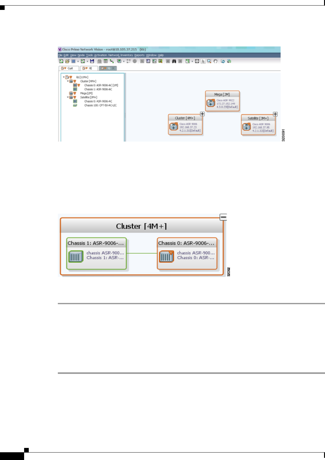
5-20
Cisco Prime Network 4.0 User Guide OL-29343-01
Chapter 5 Working with Prime Network Vision Maps
Working with Aggregations
Figure 5-9 Multichassis Devices in Map View
Viewing Inter Rack Links
Inter Rack Links (IRLs) are used to represent connectivity between the cluster hosts, Cisco ASR 9000
network elements.
Figure 5-10 Multiple Chassis in a Cluster
To view the cluster IRLs:
Step 1 In Prime Network Vision, double-click the cluster device to open the Inventory Window for the device.
Step 2 Choose the Cluster IRL container in the logical inventory of the cluster device. The content pane
displays a list of cluster IRLs with the following details:
• A End Point—Device or site that is the source of the link, hyperlinked to the inventory of the device
or site.
• Z End Point—Device or site that is the destination of the link, hyperlinked to the relevant entry in
the inventory.
Viewing Inter Chassis Links
Inter Chassis Links (ICLs) are used to represent the connectivity between the host Cisco ASR 9000
network element and the satellites. One or more satellites are connected to the host Cisco ASR 9000
series network element by using the ICLs. Figure 5-11 shows an ICL in the map view.
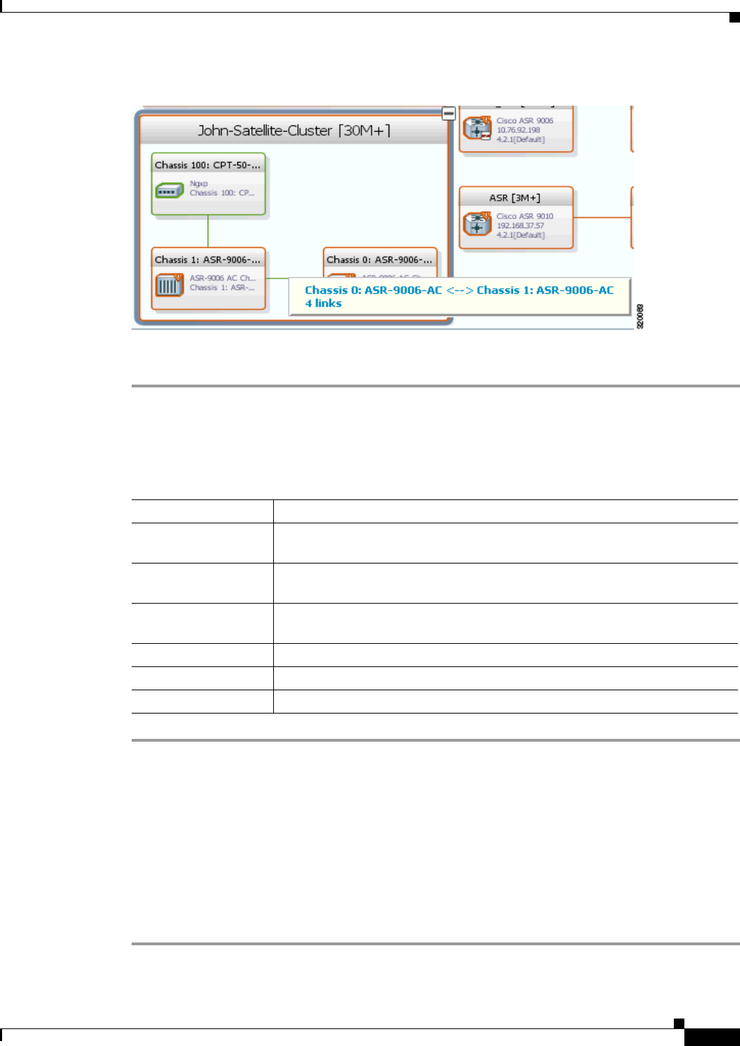
5-21
Cisco Prime Network 4.0 User Guide
OL-29343-01
Chapter 5 Working with Prime Network Vision Maps Working with Overlays
Figure 5-11 ICL Connecting a Satellite with a Chassis
To view the satellite ICLs:
Step 1 In Prime Network Vision, double-click the satellite device to open the Inventory Window for the device.
Step 2 Choose the Satellite ICL container in the logical inventory of the cluster device. The content pane
displays a list of Satellite ICLs with the following details:
Working with Overlays
When you apply an overlay to a map, you can isolate the parts of a network that are being used by a specific
service.
Applying an Overlay
To apply an overlay:
Step 1 In Prime Network Vision, choose the map in which you want to apply an overlay.
Table 5-7 Satellite ICL Properties
Field Description
Host Interface Interface by which satellite is configured on the host network element. Click
the hyperlink to view the interface properties in the physical inventory.
Satellite IC Interface Inter-chassis interface used by the satellite. Click the hyperlink to view the
satellite interface properties in the physical inventory.
Satellite ID Satellite ID. Click the hyperlink to view the satellite properties in the physical
inventory.
Satellite Port Range Port associated with the satellite.
Satellite Status Connection status of the satellite: Connected or Disconnected.
Fabric Link Status Status of the fabric link connected to the satellite.
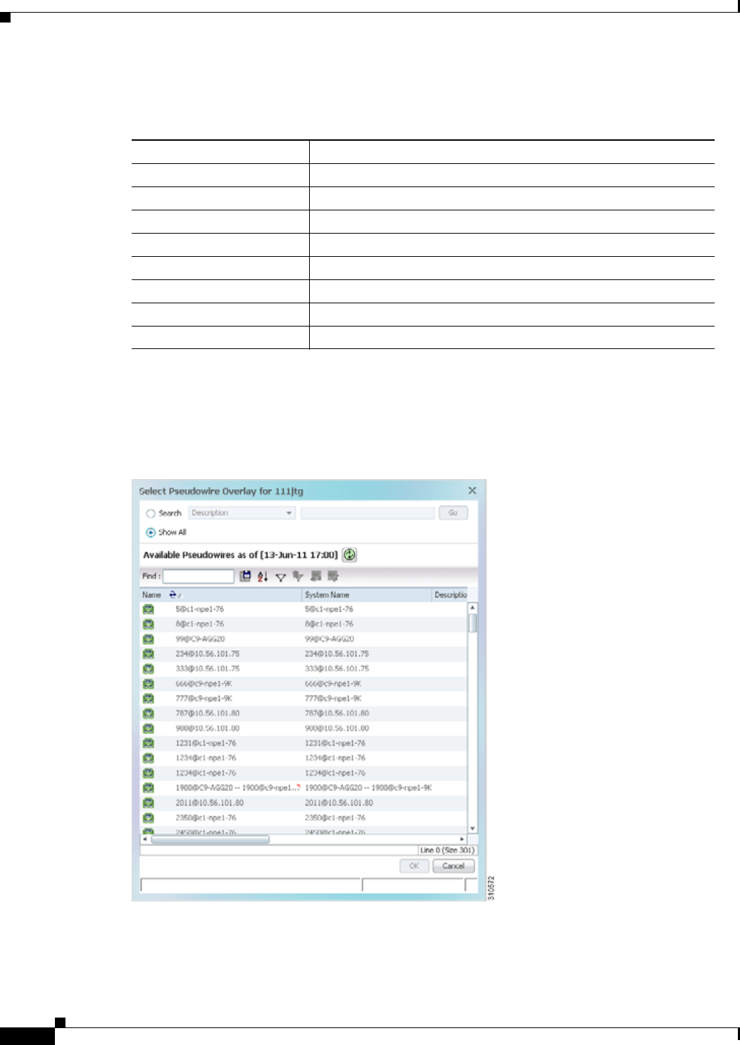
5-22
Cisco Prime Network 4.0 User Guide OL-29343-01
Chapter 5 Working with Prime Network Vision Maps
Working with Overlays
Step 2 From the toolbar, choose Choose Overlay Type > overlay-type where overlay-type is one of the
following options:
With the exception of the None option, a dialog box is displayed that allows you to select the specific
overlay to apply.
Figure 5-12 shows an example of the Select Pseudowire Overlay dialog box.
Figure 5-12 Select Pseudowire Overlay Dialog Box
Each overlay type allows you to search for specific overlays. Table 5-8 identifies the search fields
available for each overlay type.
Overlay Option Description
Ethernet Service Applies an Ethernet service overlay to the map.
MPLS-TP Tunnel Applies and MPLS-TP tunnel overlay to the map.
Network Clock Applies a network clock overlay to the map.
None Removes any existing overlays on the map.
Pseudowire Applies a pseudowire overlay to the map.
VLAN Applies a VLAN overlay to the map.
VPLS Applies a VPLS instance overlay to the map.
VPN Applies a VPN overlay to the map.

5-23
Cisco Prime Network 4.0 User Guide
OL-29343-01
Chapter 5 Working with Prime Network Vision Maps Working with Overlays
Step 3 In the Select Overlay dialog box, do either of the following:
• To search for specific overlays:
a. Choose Search.
b. In the Search field, choose a search category.
c. Enter a search string to narrow the display to a range of overlays or to a specific overlay. Table 5-8
identifies the search categories available for each type of overlay.
d. Click Go.
Search strings are case-insensitive. If you choose Name and enter NET, the overlays that contain
“net” in their names are displayed. If you choose System Name and enter System123, only the
overlay with the system named System123 is displayed.
Table 5-8 Overlay Type Search Fields
Overlay Type Search Fields
Ethernet Service • EVC Terminating EFPs
• Name
• System Name
MPLS-TP Tunnel • Description
• Name
• System Name
Network Clock • Name
Pseudowire • Description
• Is Multisegment Pseudowire
• Name
• Pseudowire Role
• Pseudowire Type
• System Name
VLAN • EFD Name
• EFD System Name
• ID
• Name
• System Name
VPLS • Name
• System Defined Name
• VPN ID
VPN • Description
• Name
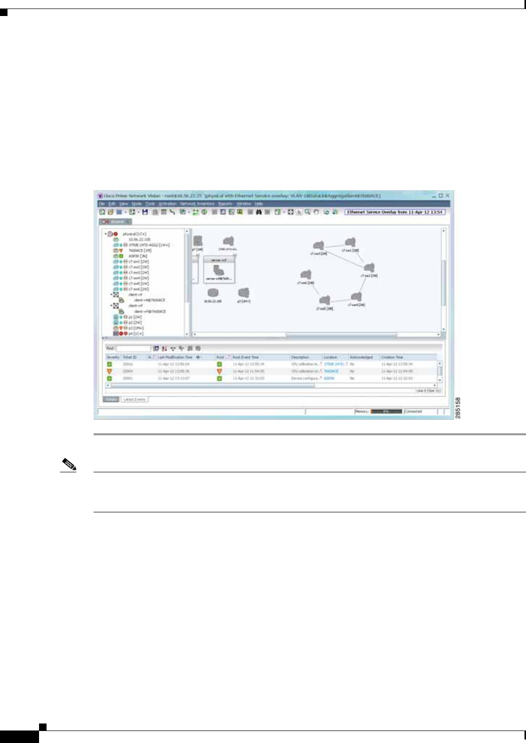
5-24
Cisco Prime Network 4.0 User Guide OL-29343-01
Chapter 5 Working with Prime Network Vision Maps
Working with Overlays
• To view all available overlays, choose Show All.
The available overlays that meet the specified search criteria are displayed in the Select Overlay dialog
box in table format. The dialog box also displays the date and time at which the list was generated. To
update the list, click Refresh.
Step 4 Select the overlay that you want to apply to the map.
The elements and links that are used by the overlay are displayed in the map, and the overlay name and
date are displayed in the toolbar, as shown in Figure 5-13.
Figure 5-13 Overlay Example
Note The overlay is a snapshot taken at a specific point in time and does not reflect changes that occur in the
service. As a result, the information in an overlay can become stale. To update the overlay, click Refresh
Overlay in the toolbar.
Hiding and Viewing Overlays, and Removing Overlays from a Map
When an overlay is applied to a map, the Show Overlay/Hide Overlay button becomes active in the
toolbar. To hide and view the overlay, click Hide Overlay/Show Overlay in the toolbar. The button
toggles depending on whether the overlay is currently displayed or hidden.
To remove an overlay, choose Choose Overlay Type > None. The overlay is removed from the map.

5-25
Cisco Prime Network 4.0 User Guide
OL-29343-01
Chapter 5 Working with Prime Network Vision Maps Filtering Links in a Map
Filtering Links in a Map
The links filter enables you to filter the links displayed in the map view and the links view. You can
quickly select the types of links to be filtered by selecting from a predefined set of link types in the list,
or by manually configuring a customized set of link types.
To filter links, do either of the following:
• Create a new map, select a filter, and then add the devices to the map. This filter is applied to the
new map and only the required link types are visible in the map view and the links view. For more
information, see Filtering Links During Map Creation, page 5-25.
• Create a map and add the devices with all links enabled and visible in the map view and links view.
You can then filter (display or hide) the different types of links as required. For more information,
see Filtering Links in an Existing Map, page 5-27.
The links filter applies to all aspects of Prime Network Vision: the map view, links view, ticket pane,
severity calculation, and other items, such as memory consumption and thresholds. Prime Network
Vision holds only the links that are relevant to the filter and synchronizes the links with the gateway
according to that filter.
For more information about links in Prime Network Vision, see Chapter 6, “Working with Links.”
Filtering Links During Map Creation
To filter links while creating a map:
Step 1 Open the Create Map dialog box by choosing File > New Map from the main menu. The Create Map
dialog box is displayed. For more information, see Creating and Deleting Maps, page 5-6.
Step 2 Click Advanced. The Link Filter dialog box is displayed.
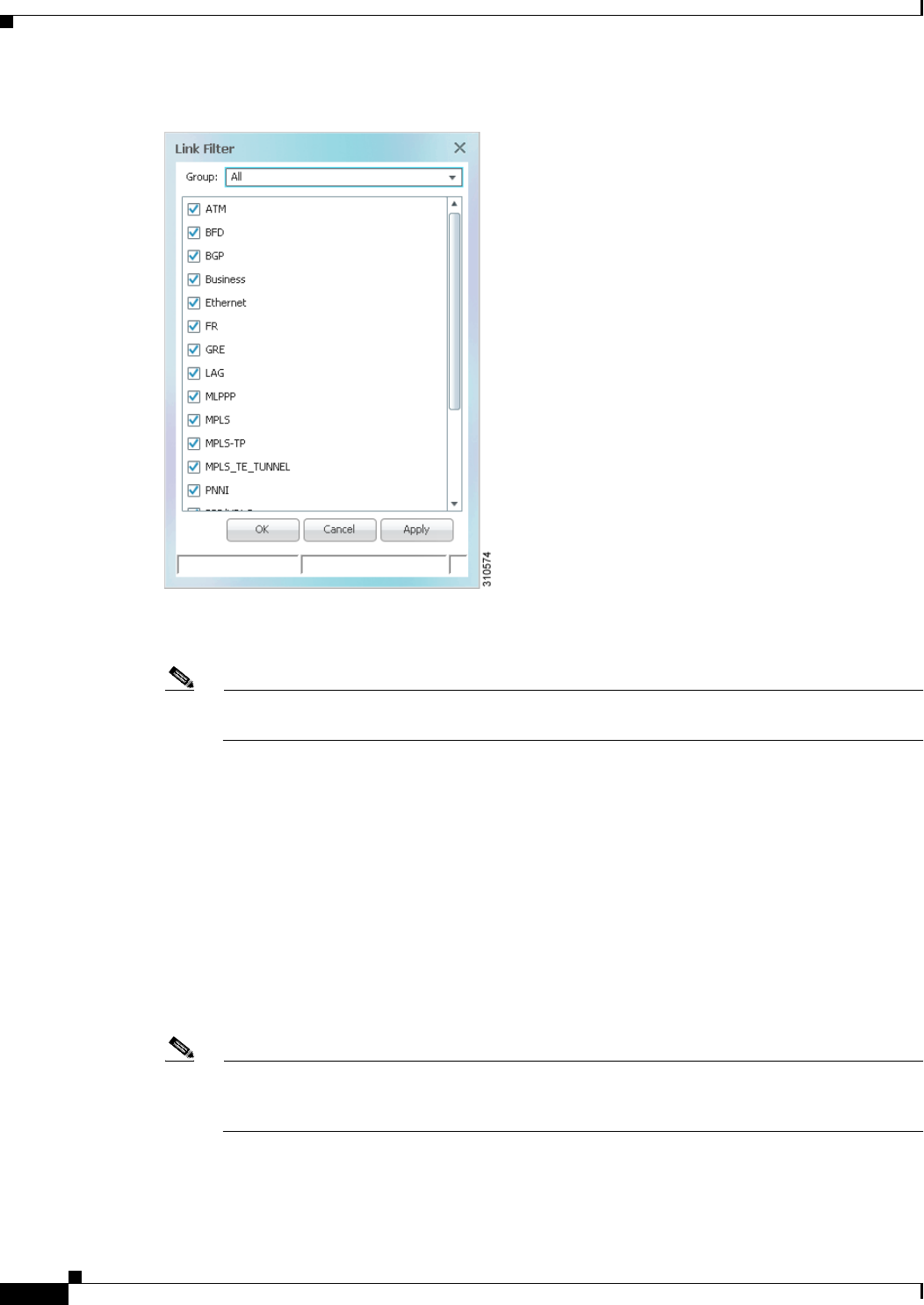
5-26
Cisco Prime Network 4.0 User Guide OL-29343-01
Chapter 5 Working with Prime Network Vision Maps
Filtering Links in a Map
Figure 5-14 Link Filter Dialog Box
The Link Filter dialog box displays a list of all the types of links that you can filter in the map view and
links view.
Note By default all link types are selected in the Link Filter dialog box. That is, all links are displayed
in the map view and links view.
Step 3 Select the required option from the Group drop-down list:
• All—All the links are displayed in the map view and links view.
• Custom—Only the links defined for the customized filter are displayed in the map view and links
view.
• Data Link—The data link layer class of links (ATM and Frame Relay) is displayed in the map view
and links view.
• None—None of the links are displayed in the map view and links view.
• Physical—Only the physical links are displayed in the map view and links view.
• VPN—Only VPN-related links (GRE, Pseudowire, VPN, and VPN IPv6) are displayed in the map
view and links view.
Note You can customize the Group drop-down list options by selecting an option and adding or
removing the required link types. The next time the Link Filter dialog box is opened, the Custom
option is displayed with the specified link types.
Step 4 Click Apply to apply the defined link filter settings and continue with more selections.
Step 5 Click OK when you have completed your selections.

5-27
Cisco Prime Network 4.0 User Guide
OL-29343-01
Chapter 5 Working with Prime Network Vision Maps Opening the CPU Usage Graph
Step 6 In the Create Map dialog box, enter a name for the new map and click OK. An empty new map is
displayed in the navigation pane and content area, and the Link Filter Applied button is displayed in the
to indicate that the links have been filtered.
Step 7 Add the required elements to the map. For more information, see Creating and Deleting Maps, page 5-6.
The links are displayed in the map view and links view according to your selections.
Filtering Links in an Existing Map
You can also create a map, add elements with all links enabled and visible in the map view and links
view, and then filter (display or hide) the different types of links as required.
To filter links in an existing map:
Step 1 Click Link Filter in the main toolbar.
Step 2 In the Link Filter dialog box, uncheck the check boxes for the links that you do not want to display in
the map view and links view.
Step 3 Click Apply to apply the defined link filter settings and continue with more selections.
Step 4 Click OK when you have completed your selections.
The links are displayed in the map view and links view according to the defined filter, and the Link Filter
Applied button is displayed in the to indicate that the links are filtered.
Opening the CPU Usage Graph
Prime Network Vision enables you to display memory and CPU usage information for a device or
network element, including its history.
To open the CPU usage graph:
Step 1 Right-click a network element in the navigation tree and choose Tools > CPU Usage.
The CPU Usage dialog box displays the following information:
• CPU Usage—The CPU usage rate as a percentage.
• CPU Usage History—The CPU usage rate history is graphically displayed.
• Memory Usage—The memory usage rate as a percentage.
• Memory Usage History—The memory usage rate history is graphically displayed.
Step 2 If desired, click Save to CSV File to export the displayed data.
Step 3 Click the upper right corner to close the CPU Usage dialog box.

5-28
Cisco Prime Network 4.0 User Guide OL-29343-01
Chapter 5 Working with Prime Network Vision Maps
Communicating with Devices Using Ping and Telnet
Communicating with Devices Using Ping and Telnet
Prime Network Vision enables you to communicate with devices in the following ways:
• Pinging a Device, page 5-28
• Telneting a Device, page 5-28
Pinging a Device
Prime Network Vision enables you to ping a device to verify that the device is responding.
The ping is performed from the client to the device, and not from the Prime Network Vision unit hosting
the VNE to the device.
To ping a device, right-click a device in the navigation tree or map, and choose Tools > Ping.
The results are displayed in a new window.
Telneting a Device
Prime Network Vision enables you to communicate with a device using the Telnet window.
The Telnet session is performed from the client to the device, and not from the Prime Network Vision
unit hosting the VNE to the device.
Note If you are using a Windows 7 system, you must enable the Windows Telnet Client before you can use
the Prime Network Telnet option.
- For Windows 7 32-bit systems, enable the Windows Telnet Client to use the Prime Network Telnet
option.
- For Windows 7 64-bit systems, a solution is available on the Cisco Developer Network at
http://developer.cisco.com/web/prime-network/forums/-/message_boards/message/2780108.
To telnet a device:
Step 1 Right-click a device in the navigation tree or map, and choose Tools > Telnet. A terminal window opens.
Step 2 Log in and use the Telnet window as needed.

CHAPTER
6-1
Cisco Prime Network 4.0 User Guide
OL-29343-01
6
Working with Links
The following topics describe how to view information about static and dynamic links using the
Cisco Prime Network Vision (Prime Network Vision) user interface:
• User Roles Required to Work with Links, page 6-1
• What Are Dynamic and Static Links?, page 6-3
• Link Discovery and Flickering Ethernet Topology Links, page 6-3
• Viewing Link Properties, page 6-4
• Viewing Link Impact Analysis, page 6-12
• Adding Static Links, page 6-15
• Filtering Links Using the Collection Method, page 6-17
• Selecting a Link, page 6-18
User Roles Required to Work with Links
This topic identifies the GUI default permission or element scope security level that is required to work
with links in Prime Network Vision. Prime Network determines whether you are authorized to perform
a task as follows:
• For GUI-based tasks (tasks that do not affect elements), authorization is based on the default
permission that is assigned to your user account.
• For element-based tasks (tasks that do affect elements), authorization is based on the default
permission that is assigned to your account. That is, whether the element is in one of your assigned
scopes and whether you meet the minimum security level for that scope.
For more information on user authorization, see the Cisco Prime Network 4.0 Administrator Guide.
The following tables identify the tasks that you can perform:
• Table 6-1 identifies the tasks that you can perform if a selected element is not in one of your
assigned scopes.
• Table 6-2 identifies the tasks that you can perform if a selected element is in one of your assigned
scopes.
By default, users with the Administrator role have access to all managed elements. To change the
Administrator user scope, see the topic on device scopes in the Cisco Prime Network 4.0 Administrator
Guide.

6-2
Cisco Prime Network 4.0 User Guide OL-29343-01
Chapter 6 Working with Links
User Roles Required to Work with Links
Table 6-1 Default Permission/Security Level Required for Working with Links - Element Not in
User’s Scope
Task Viewer Operator OperatorPlus Configurator Administrator
View link properties in
Map view X1
1. Link properties are limited in the Map view; not all link information is available.
X1X1X1X
View link properties in
Links view X2
2. Link properties are limited in the Links view; not all link information is available.
X2X2X2X
View link properties in
the Link Properties
window
————X
View link impact
analysis ————X
Add static links — — — — X
Filter links using
collection method XXXXX
Find and select a link in
a map XXXXX
Table 6-2 Default Permission/Security Level Required for Working with Links - Element in
User’s Scope
Task Viewer Operator OperatorPlus Configurator Administrator
View link properties in
Map view XXXXX
View link properties in
Links view X1
1. Link properties are limited in the Links view; not all information is available.
X1X1X1X
View link properties in
the Link Properties
window
XXXXX
View link impact
analysis ————X
Add static links — — — X X
Filter links using
collection method XXXXX
Find and select a link in
a map XXXXX

6-3
Cisco Prime Network 4.0 User Guide
OL-29343-01
Chapter 6 Working with Links What Are Dynamic and Static Links?
What Are Dynamic and Static Links?
Dynamic links are the physical and logical links that exist between elements in the network. These links
are discovered by Prime Network using various protocols (such as STP, CDP, and LLDP). The ongoing
process of autodiscovery maintains this topological information. Property information is provided for
links that are:
• Between two devices.
• Between a device and an aggregation that connects this device to another device inside the
aggregation.
• Between two aggregations that contain devices that cross the aggregations.
If a link is unidirectional, Prime Network Vision displays an arrowhead on the link. If it is bidirectional,
an arrowhead is not displayed.
Static links are links that are created at the VNE level but are not updated. These links do not perform
any configuration or provisioning on a device or in the network. Static links are useful for map
visualization and network correlation; for example, if Prime Network Vision does not discover a link that
you know exists in the network, you can create a static link that is displayed in the map. For correlation
purposes, Prime Network Vision treats the static link as if it were a physical or logical link and allows
correlation flows to go through the static link. For information on creating static links, see Adding Static
Links, page 6-15.
Link Discovery and Flickering Ethernet Topology Links
As mentioned in What Are Dynamic and Static Links?, page 6-3, Prime Network discovers topology
links using various protocols, such as STP, CDP, and LLDP. In some situations, the link configurations
themselves can prevent Prime Network from discovering the correct information. For example, if
Layer 2 protocol tunneling is configured and the discovery protocols are tunneled, Prime Network can
create an incorrect link. This scenario results in a flickering link that is first created incorrectly due to
tunneled discovery information, and then disconnected when the Prime Network counters test discovers
that the counters on the edges of the link do not match. During the next topology cycle, Prime Network
recreates the link, which is disconnected again during the counters test.
A link is considered flickering when it is connected, disconnected, and reconnected when using the same
connection technique because the topology information is conflicting. When this situation occurs, Prime
Network generates a system event with the message “Physical Link discovery inconsistent.”
To prevent an ongoing cycle of link creation and disconnecting, Prime Network detects such case of
flickering links, creates a system event with the message “Inconsistent Physical Link Discovery between
system:interface1 and system:interface2,” and stops the link from flickering by disconnecting it.
To remedy the situation, we recommend that you wait until the link disappears from the map and then
create a static link.
Note This feature applies only to Ethernet links.
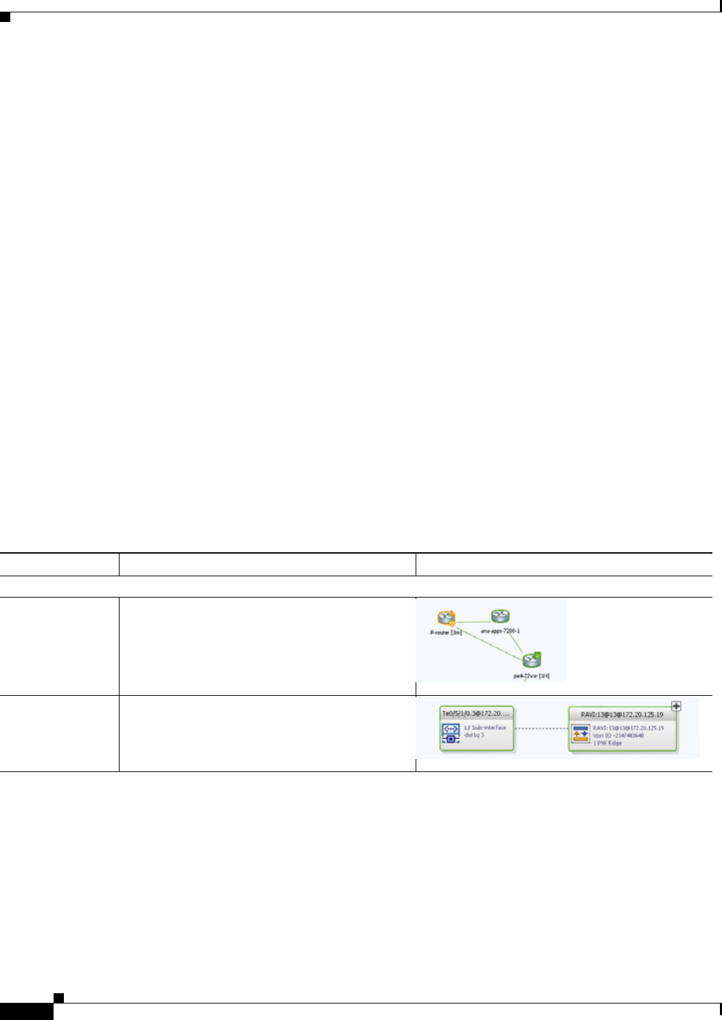
6-4
Cisco Prime Network 4.0 User Guide OL-29343-01
Chapter 6 Working with Links
Viewing Link Properties
Viewing Link Properties
In maps, you can view a link only if both ends of the link are in your scope. However, Prime Network
Vision provides an option that allows users to view links and any associated tickets if only one end of
the link is in your scope. For more information about this option, see the Cisco Prime Network 4.0
Administrator Guide.
Prime Network Vision provides information about links in the following ways:
• Through the physical characteristics of the link in a map, tooltips, and link quick views—See
Viewing Link Properties in Prime Network Vision Maps, page 6-4.
• In the Links view—See Viewing Link Properties in the Links View, page 6-8.
• In the link properties window—See Viewing Link Properties in the Link Properties Window,
page 6-10.
Viewing Link Properties in Prime Network Vision Maps
The representation of a link in a map provides information about that link. The characteristics that
provide information about a link are:
• Whether the link is solid or dashed.
• Whether or not the link displays an arrow at one end.
• Link color.
Table 6-3 describes the link variations that can be displayed in a map and provides examples of each.
Table 6-3 Link Properties in Prime Network Vision Maps
Link Characteristic Description Example
Solid Line vs. Dashed Line
Solid line Physical, topological, or service link, such as a
link between two devices.
Dashed line Association or business link between such
elements as EVCs, VPLS service instances, or
VPN components.
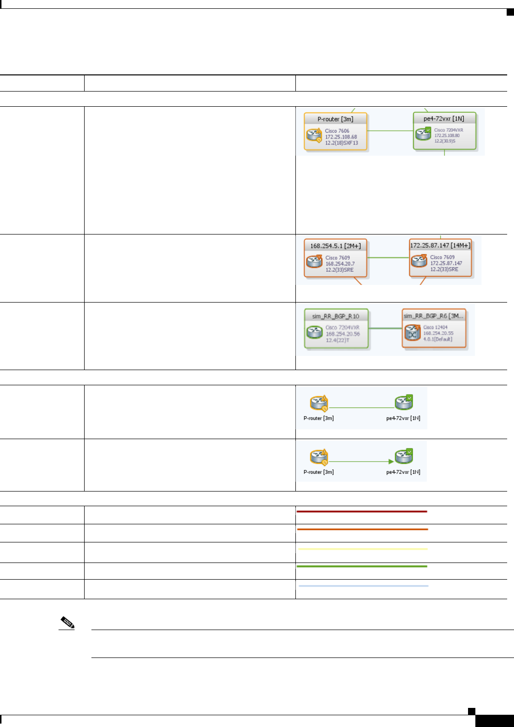
6-5
Cisco Prime Network 4.0 User Guide
OL-29343-01
Chapter 6 Working with Links Viewing Link Properties
Note The color of a selected link is customizable. The default color is blue. For more information on link
colors, see Map View, page 2-8.
Link Widths
Normal Contains links of the same group. Available
groups are:
• Business
• GRE
• MPLS-TP
• Pseudowire
• VLAN
• All others
Wide Aggregated links that contain links of different
groups.
When viewing a map at a low zoom level,
aggregated links cannot be distinguished in the
GUI.
Tunnel A tunnel, with the center color representing the
severity of any alarms on the link.
Arrowhead vs. No Arrowhead
No arrowhead Bidirectional link.
Arrowhead Unidirectional link, with the flow in the direction
of the arrowhead.
Link Color
Red Critical alarm is on the link.
Orange Major alarm is on the link.
Yellow Minor alarm is on the link.
Green Link is operating normally.
Blue Link is selected.
Table 6-3 Link Properties in Prime Network Vision Maps (continued)
Link Characteristic Description Example
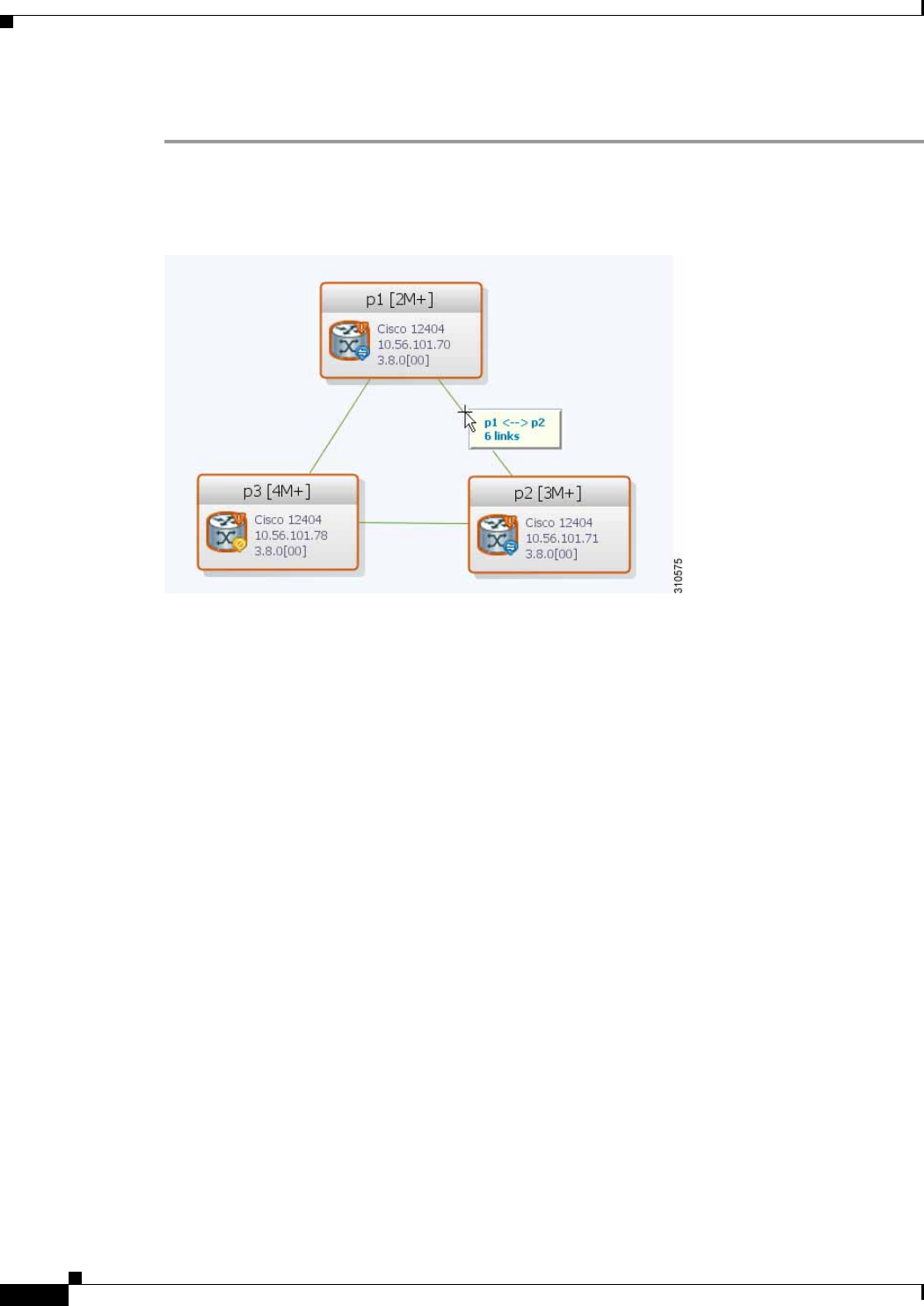
6-6
Cisco Prime Network 4.0 User Guide OL-29343-01
Chapter 6 Working with Links
Viewing Link Properties
To view link properties:
Step 1 Hover your mouse cursor over the required link in a map. A link tooltip is displayed as shown in
Figure 6-1.
Figure 6-1 Link Tooltip in Prime Network Vision
The tooltip contains the following information about the link:
• Link endpoints, identified by the element or service name.
• The number of links represented by the line on the map.
Examples of tooltips are:
• 169.254.12.34 <--> 169.254.56.78 6 links
• 22@169.254.12.34 <--> CEM1/2:1@169.254.56.78 1 link
Step 2 To view additional link information, click the tooltip. The link quick view window is displayed as shown
in Figure 6-2.
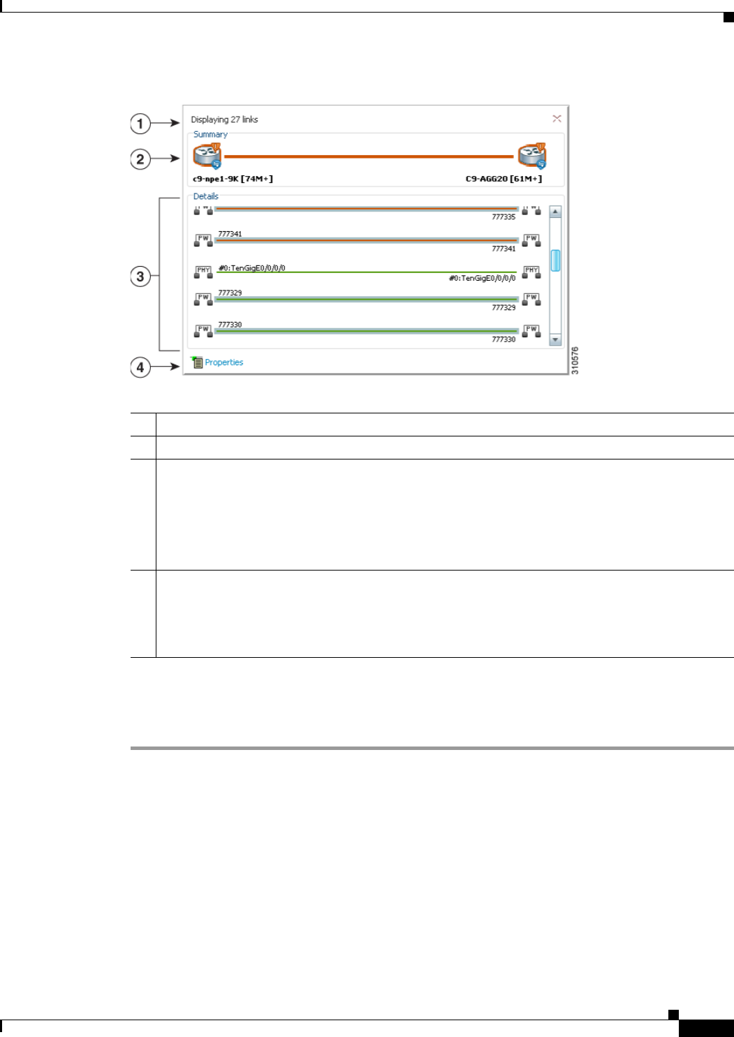
6-7
Cisco Prime Network 4.0 User Guide
OL-29343-01
Chapter 6 Working with Links Viewing Link Properties
Figure 6-2 Link Quick View Example
Step 3 To view more link properties, click Properties in the link quick view.
For more information about the link properties window, see Viewing Link Properties in the Link
Properties Window, page 6-10.
1Number of links represented by the single link in the map. In this example, 29 links.
2Link endpoints.
3List of all links represented by the link in the map with the following information, as appropriate:
• Type of link, such as Physical, MPLS, or Tunnel. For a complete list of the types of links and
their abbreviations, see Link Icons, page A-11.
• Link detail, such as the interface used on each endpoint, service name, or type of service.
• Link alarm status, indicated by the link color.
4Hyperlink to the link properties window.
The Properties button is available for physical, topographical, and service links, but is not
available for business links (dashed links).
For more information, see Viewing Link Properties in the Link Properties Window, page 6-10.
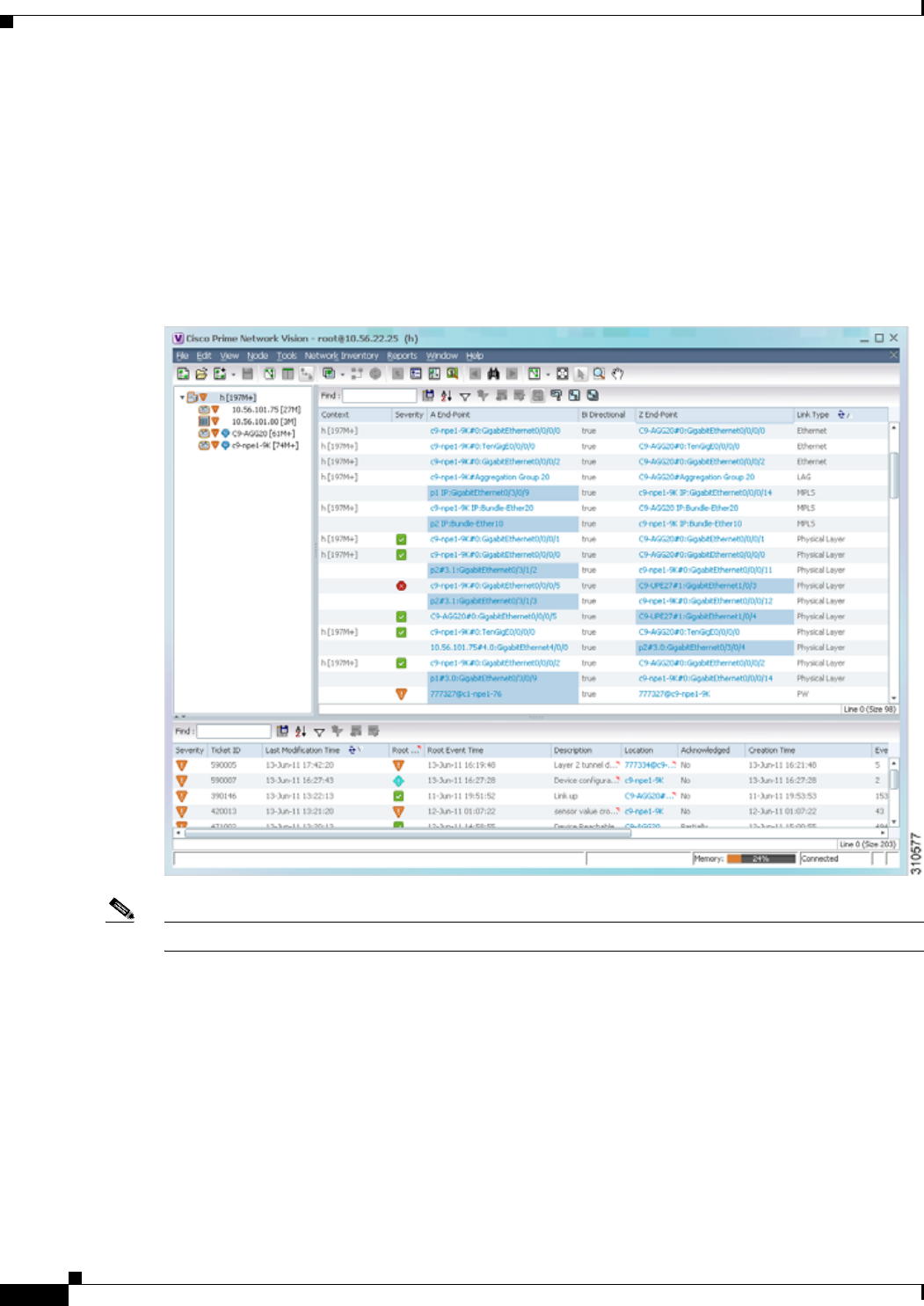
6-8
Cisco Prime Network 4.0 User Guide OL-29343-01
Chapter 6 Working with Links
Viewing Link Properties
Viewing Link Properties in the Links View
The links shown in a map represent many other links as described in Viewing Link Properties in Prime
Network Vision Maps, page 6-4. By using the links view, you can view a list of all links represented in
a map and their status.
To display the links view in the Prime Network Vision window, click Show Links View in the main
toolbar. Figure 6-3 shows an example of the links view.
Figure 6-3 Links View
Note A link external to the network has a blue cell background in the table.
Any links that are added or removed from the map are automatically added or removed from the links
view, provided they have not been filtered out.

6-9
Cisco Prime Network 4.0 User Guide
OL-29343-01
Chapter 6 Working with Links Viewing Link Properties
Table 6-4 describes the information that is displayed in the links view.
By default, the links displayed in the links view are sorted according to link type and the deep collection
method.
The buttons in Table 6-5 are displayed at the top of the links view and enable you to filter the links
according to the collection method.
Note If you load a map with many links (for example, thousands of links), it can take a while for the complete
list of links to load. The filtering options in the table are unavailable until the table has completely
loaded.
Table 6-4 Links View Content
Field Description
Context Name of the map or aggregation containing the link. The links view
can include multiple contexts.
This field can be empty for either of the following reasons:
• One side of the link is not included in the map.
• The link is filtered out of all contexts.
Severity Severity bell icon, colored according to the severity of the alarm on
the link and indicating the impact of the alarm on the network. For
more information, see Prime Network Vision Status Indicators,
page 2-17.
A End Point Device or site that is the source of the link, as a hyperlink to the
inventory of the device or site.
Bidirectional Whether the link is bidirectional or unidirectional: True
(bidirectional) or False (unidirectional).
Z End Point Device or site that is the destination of the link, hyperlinked to the
relevant entry in inventory.
Link Type Type of link, such as Physical Layer, VPN, MLPPP, or MPLS.
Table 6-5 Links View Tools
Icon Name Description
All Links Complete list of links for the selected map or aggregation.
External
Links Links with one side of the link in the selected map or aggregation and the other
side of the link outside the currently selected map or aggregation.
Flat Links Links currently visible in the map pane for the selected map or aggregation,
excluding any thumbnails.
Deep
Links Links for the selected aggregation and any nested aggregations, with both
endpoints within the currently selected map or aggregation.
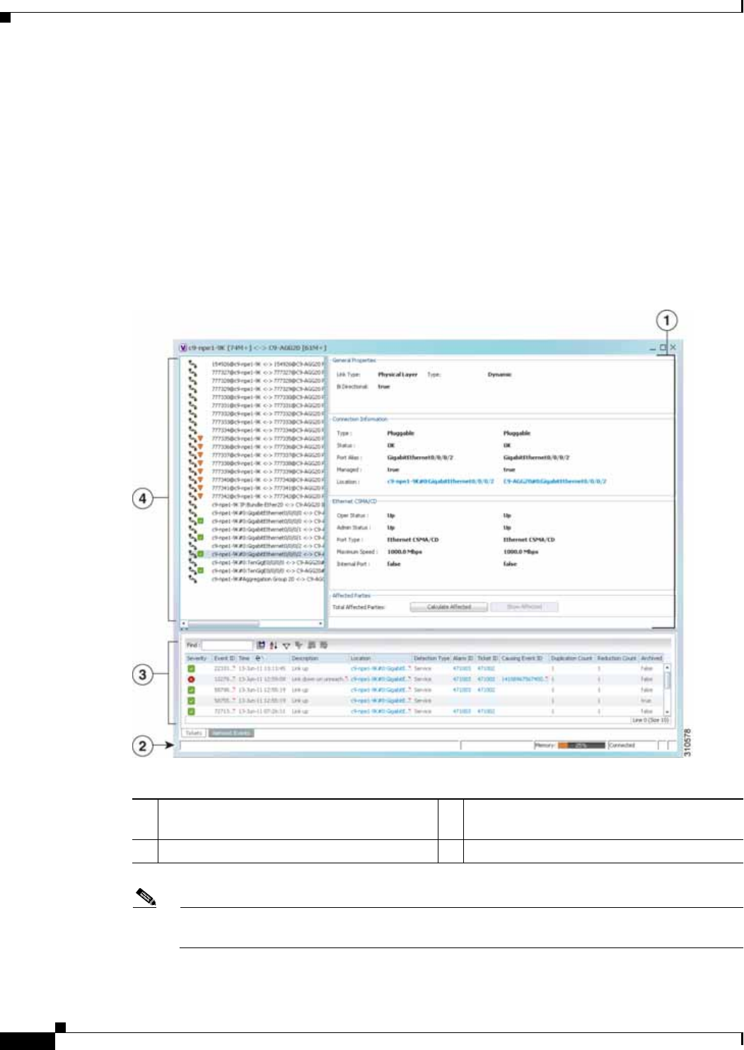
6-10
Cisco Prime Network 4.0 User Guide OL-29343-01
Chapter 6 Working with Links
Viewing Link Properties
For more information about filtering links using the collection method, see Filtering Links Using the
Collection Method, page 6-17.
Viewing Link Properties in the Link Properties Window
The link properties window contains general information about the selected link, details of the link
connection, and technology-specific information appropriate for the link.
In a Prime Network Vision map, open the link properties window by right-clicking a link and choosing
Properties. The link properties window is displayed as shown in Figure 6-4.
Figure 6-4 Link Properties Window
Note If multiple links exist between the elements or aggregations, the link properties window displays
information for all the links.
1Properties pane (see Properties Pane,
page 6-11)3 Ticket and events pane (see Ticket and Events
Pane, page 3-15)
2Status bar 4 Link list pane (see Link List Pane, page 6-11)

6-11
Cisco Prime Network 4.0 User Guide
OL-29343-01
Chapter 6 Working with Links Viewing Link Properties
The information displayed in the link properties window changes according to the ports or subports
selected in the link list pane.
Link List Pane
In the link properties window, the link list pane displays a list of the links that are represented by a single
link on the map. Each link has a single entry in the link list pane.
When an entry is selected in the link list pane, the information displayed in the properties pane is
updated. The color of the icon in the link list pane reflects its severity. For more information about
severity, see Prime Network Vision Status Indicators, page 2-17.
The heading and the link list pane display the left and right link identifiers between the two nodes, the
device alias, and Connection Termination Point (CTP).
Properties Pane
The properties pane enables you to view the following, depending on your selection in the link list pane:
• Properties of a selected link, including port properties information.
• Hyperlinks to relevant entries in logical or physical inventory.
• Status.
The properties pane displays the link type, port alias, and port location, all of which uniquely identify
the port. The port location information is also displayed as a hyperlink to the inventory window.
The properties pane also displays the parameters for each end of the link, aligned under the relevant link
identifier. Any discrepancies between the link’s ports are displayed in red.
The following fields are displayed in the Connection Information area for physical links:
• Type—Type of connector, such as fiber optic.
• Status—Status of the link, such as OK.
• Port Alias—Name used in the device CLI or EMS for the selected port.
• Managed—Whether or not the link is managed: True or False.
• Pluggable Port State—Whether or not a pluggable module is inserted.
• Location—Location of the entity, slot number, and port on the slot, as a hyperlink that opens the
properties of the relevant location.
Depending on the link and its configuration, the following areas containing status and configuration
information are displayed in the properties pane:
• Ethernet CSMA/CD
• Gigabit Ethernet
• LAG
• MLPPP
• MP-BGP
• MPLS Link Information
• PPP
• Pseudowire

6-12
Cisco Prime Network 4.0 User Guide OL-29343-01
Chapter 6 Working with Links
Viewing Link Impact Analysis
• T1
• VRF
IP addresses are displayed in IPv4 or IPv6 format, as appropriate.
Depending on the type of link, the following areas might be displayed:
• Affected Parties—Enables you to view all elements potentially affected by the link. For more
information, see Viewing Link Impact Analysis, page 6-12.
• Labels—Enables you to view all LSPs on an Ethernet link. For more information, see Viewing LSPs
Configured on an Ethernet Link, page 18-11.
• VCs—Enables you to view configured and misconfigured VCs on an ATM link. For more
information, see Viewing ATM VPI and VCI Properties, page 20-10.
Ticket and Events Pane
The ticket and events pane is displayed at the bottom of the link properties window and contains the
following tabs:
• Tickets—Displays the tickets that are collected on the selected element, service, or component in
the navigation pane.
Table 9-3 describes the information that is available in the Tickets tab.
• Network Events—Displays all active network events associated with tickets and alarms, and all
archived events with a timestamp that falls within the specified events history size (see Adjusting
the Prime Network Vision GUI Client Settings, page 2-40).
Table 3-7 on page 3-15 describes the information that is available in the Network Events tab.
When displaying network events, Prime Network Vision monitors the history size value defined in the
Events tab of the Options dialog box (Tools > Options > Events). The default value is six hours and can
be changed in Prime Network Administration. In addition, Prime Network Vision limits the maximum
number of network and provisioning events that are sent from the server to client to 15,000 each. If the
number of network or provisioning events exceeds the limit specified in the Options Events tab or the
15,000 maximum limit, Prime Network Vision purges the oldest events from table. The purging
mechanism runs once per minute.
Tip You can display or hide the ticket and events pane by clicking the arrows displayed below the device
view panel.
Viewing Link Impact Analysis
Prime Network Vision enables you to select a network link and calculate the elements that might be
affected if the link were to go down. This enables you to perform proactive impact analysis when a fault
has not actually occurred.
Note Impact analysis applies only to physical links.
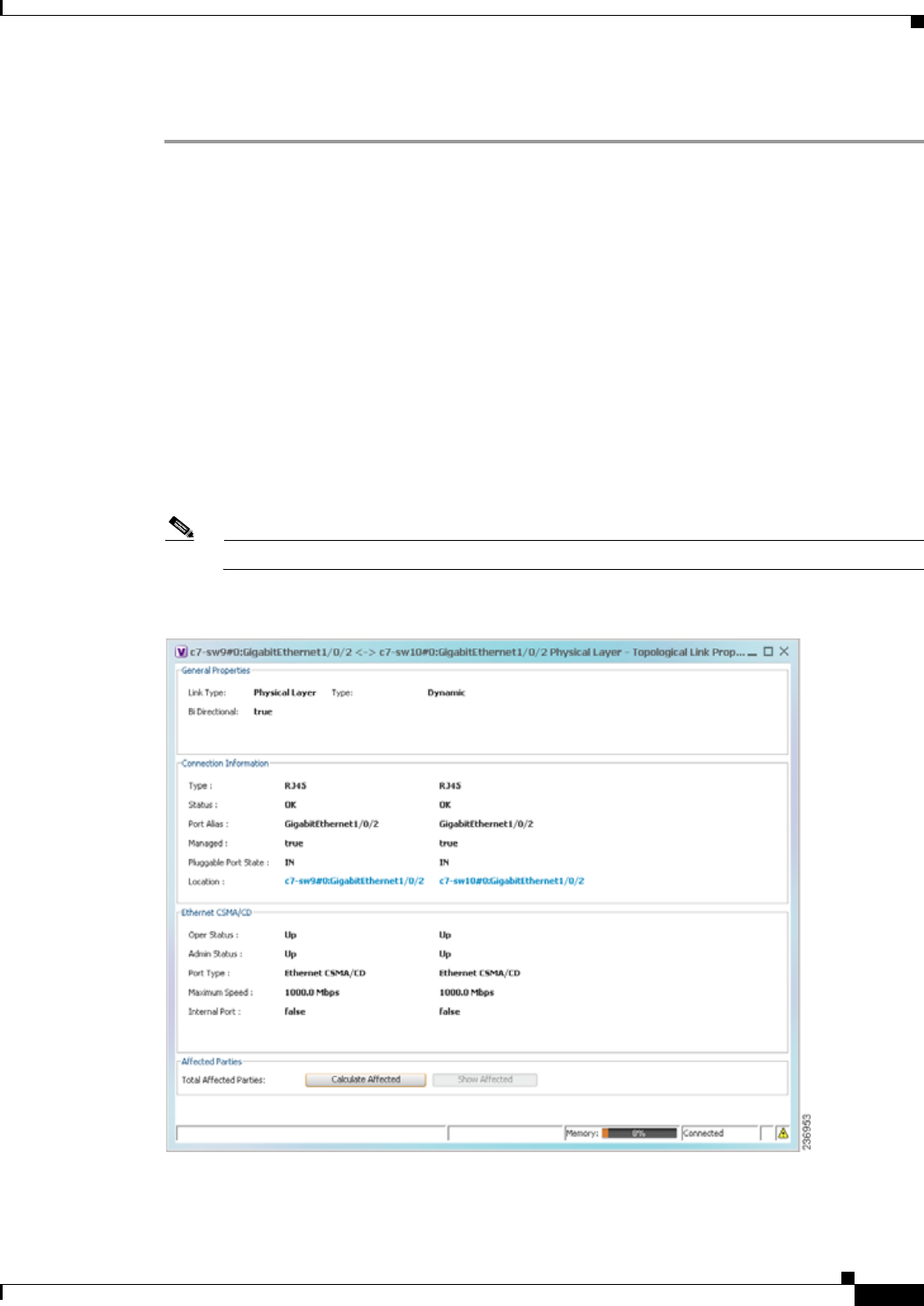
6-13
Cisco Prime Network 4.0 User Guide
OL-29343-01
Chapter 6 Working with Links Viewing Link Impact Analysis
To calculate impact analysis:
Step 1 Select a map or aggregation in the navigation pane, and click Show Links View in the main toolbar. The
links view is displayed in the content pane.
Step 2 In the table toolbar, click Link Filter. The Link Filter dialog box is displayed. For information about the
Link Filter dialog box, see Filtering Links in a Map, page 5-25.
Step 3 In the Filter dialog box:
a. In the Match drop-down list, choose All.
b. In the field drop-down list, choose Link Type.
c. In the operand drop-down list, choose Equals.
d. In the matching criteria drop-down list, choose Physical Layer.
e. Click OK.
Only physical links are displayed in the links view.
Step 4 In the links view, right-click the required link and choose Properties. The Topological Link Properties
window is displayed.
Note Resize the window as needed to view all the information.
Figure 6-5 Topological Link Properties Window
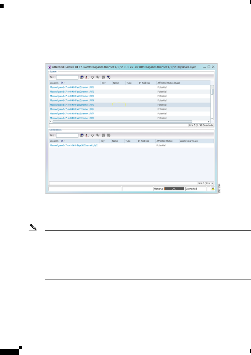
6-14
Cisco Prime Network 4.0 User Guide OL-29343-01
Chapter 6 Working with Links
Viewing Link Impact Analysis
Step 5 Click Calculate Affected. The total number of potentially affected parties is displayed in the Affected
Parties area.
Step 6 Click Show Affected. The Affected Parties window is displayed as shown in Figure 6-6.
Figure 6-6 Affected Parties Window
Step 7 To view the potentially affected destinations if a link were go to down, click an entry in the Source table.
The potentially affected destinations are displayed in the Destination table.
Step 8 To view source or destination properties in inventory, click the required hyperlinked entry.
Note The Affected Parties window occasionally displays entries that start with the word Misconfigured.
Entries that start with Misconfigured indicate that the flow has stopped unexpectedly between the source
and destination points. An unexpected termination point can be a routing entity, bridge, or VC switching
entity. The significant aspects of Misconfigured entries are:
- Because the link does not terminate as expected, the link is not actually impacted.
- An error might exist in the configuration or status of the termination points.
We recommend that you check the configuration and status of the affected termination points.

6-15
Cisco Prime Network 4.0 User Guide
OL-29343-01
Chapter 6 Working with Links Adding Static Links
Adding Static Links
Prime Network Vision enables you to create static links that exist only on the VNE level. Static links are
useful for visualization and network correlation because Prime Network Vision allows correlation flows
to go through the links, as if they were real physical or logical links. Static link properties are not updated
because the links do not really exist in the network.
To create a static link, select a device or port and define it as the A side. Then define a second device or
port as the Z side. Prime Network Vision validates the new link after the two ports are selected.
Validation checks the consistency of the port types (for example, RJ45 on both sides), and Layer 2
technology type (for example, ATM OC-3 on both sides).
You can also create static links between Ethernet Link Aggregation Groups (LAGs) by choosing a LAG
and the desired port channel for the A or Z side as described in the following procedure.
When you add a new link, the color of the link reflects its current state. For example, if the operation
status of a port is down, the link is colored red. You can add links from either the Prime Network Vision
window’s navigation and a map, or from the inventory window navigation pane.
In addition, you can add a new link using Cisco Prime Network Administration. For more information,
see the Cisco Prime Network 4.0 Administrator Guide.
Adding a Link Using a Map and Its Navigation Pane
Step 1 Right-click the required A Side device in the navigation pane or in a map, and choose Topology > Mark
as A Side.
Step 2 Right-click the required Z Side device or LAG in the navigation pane or properties pane to display the
right-click menu and choose Topology > Mark as Z Side. The Create Static Link window is displayed
as shown in Figure 6-7, so that you can select the ports to connect.
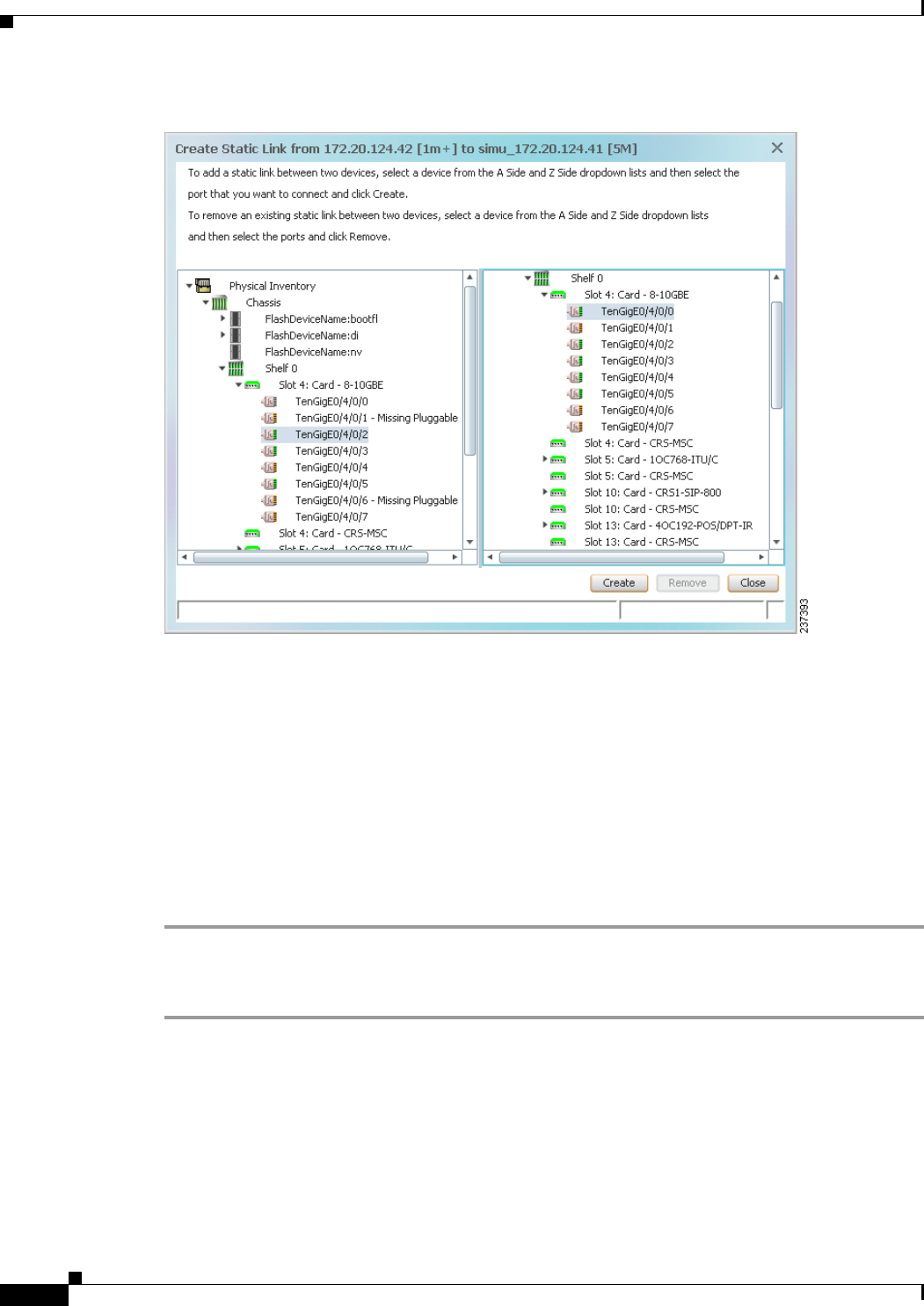
6-16
Cisco Prime Network 4.0 User Guide OL-29343-01
Chapter 6 Working with Links
Adding Static Links
Figure 6-7 Create Static Link Window
Step 3 Select the required port on both the A Side device and the Z Side device.
Step 4 Click Create to validate the connection and create the new link.
A success message is displayed.
A warning message is displayed if any of the following apply:
• A validation check fails.
• The operation status of one port is Up and the other port is Down.
• The selected ports are not of the same type.
• The Layer 2 technology type is not the same.
• One of the ports is part of another link.
Adding a Link Using the Inventory Window
Step 1 Open the inventory window for the required A Side device.
Step 2 In the navigation pane, navigate to the required port or LAG.
Step 3 Right-click the required port or LAG and choose Topology > Mark as A Side.
Step 4 Repeat Step 1 and Step 2 for the Z Side port or LAG.
Step 5 Right-click the required port or LAG and choose Topology > Mark as Z Side. A confirmation message
is displayed.

6-17
Cisco Prime Network 4.0 User Guide
OL-29343-01
Chapter 6 Working with Links Filtering Links Using the Collection Method
Step 6 Click Yes.
The ports are connected, and a link is created between the selected ports.
A warning message is displayed if any of the following conditions exist:
• One of the validation checks fails.
• The operation status of one port is Up and the other port is Down.
• The ports selected are not of the same type.
• The Layer 2 technology type is not the same.
• One of the ports is part of another link.
For information about removing a static link, see the Cisco Prime Network 4.0 Administrator Guide.
Filtering Links Using the Collection Method
The links view table enables you to view links that are not displayed graphically in the Prime Network
Vision window map pane. The links view table is dynamic and automatically refreshes itself so that you
can view up-to-date network links in real time.
The collection method enables you to filter the links displayed in the links view by selecting the
collection method from the toolbar.
Note • The deep collection method is applied by default in the links view.
• The filter applies only to the links view; it has no effect elsewhere in Prime Network Vision.
To filter links according to the collection method:
Step 1 Click Show Links View in the Prime Network Vision main toolbar.
Step 2 Select a map or aggregation in the navigation pane or links view.
Step 3 In the links view toolbar, click one of the following buttons in the toolbar:
• All Links
• External Links
• Flat Links
• Deep Links
The links are displayed in the links view according to the selected collection method.

6-18
Cisco Prime Network 4.0 User Guide OL-29343-01
Chapter 6 Working with Links
Selecting a Link
Selecting a Link
Prime Network Vision enables you to select a link listed in the links view and highlight the link in the
map in the content pane.
To select and highlight a link in a map:
Step 1 In the Links view, right-click the required link and choose Select Link in Map. The link is displayed in
blue in the map.
Step 2 If two or more links are the same (for example, two VRF links), but they are in different contexts or
aggregations, the Select Link Context dialog box is displayed. Select the required context from the
drop-down list, then click OK. The link is displayed in blue in the map.
Step 3 To remove the blue highlight from the selected link, click the map background.

CHAPTER
7-1
Cisco Prime Network 4.0 User Guide
OL-29343-01
7
Labeling NEs Using Business Tags
A business tag is a string that is meaningful to the business, and which can be used to label a component
of a network element for use in Prime Network screens and reports.
Business tags are normally applied to a business element, which is a construction or organization of
certain network elements and their properties into a logical entity. This provides users with the ability to
track them in a way that makes sense from a business perspective. Examples of business elements
include Layer 2 VPNs, Layer 3 VPNs, and virtual routers.
The following topics describe how to manage and view Cisco Prime Network Vision business tags and
business elements:
• User Roles Required to Work with Business Tags and Business Elements, page 7-1
• Using Chinese Characters, page 7-2
• Attaching and Detaching Business Tags, page 7-3
• Searching for Business Tags and Viewing Their Properties, page 7-4
• Renaming a Business Element, page 7-7
• Deleting a Business Element, page 7-7
User Roles Required to Work with Business Tags and Business
Elements
This topic identifies the roles that are required to work with business tags and business elements. Prime
Network determines whether you are authorized to perform a task as follows:
• For GUI-based tasks (tasks that do not affect elements), authorization is based on the default
permission that is assigned to your user account.
• For element-based tasks (tasks that do affect elements), authorization is based on the default
permission that is assigned to your account. That is, whether the element is in one of your assigned
scopes and whether you meet the minimum security level for that scope.
For more information on user authorization, see the Cisco Prime Network 4.0 Administrator Guide.
The following tables identify the tasks that you can perform:
• Table 7-1 identifies the tasks that you can perform if a selected element is not in one of your
assigned scopes.
• Table 7-2 identifies the tasks that you can perform if a selected element is in one of your assigned
scopes.

7-2
Cisco Prime Network 4.0 User Guide OL-29343-01
Chapter 7 Labeling NEs Using Business Tags
Using Chinese Characters
By default, users with the Administrator role have access to all managed elements. To change the
Administrator user scope, see the topic on device scopes in the Cisco Prime Network 4.0 Administrator
Guide.
Using Chinese Characters
Cisco Prime Network Vision supports Chinese characters in business tags, enabling you to perform the
following activities using Chinese characters:
• Create a business tag—Attaching and Detaching Business Tags, page 7-3.
• Search for business tags and view business tag properties—Searching for Business Tags and
Viewing Their Properties, page 7-4.
Table 7-1 Default Permission/Security Level Required for Working with Business Tags and
Business Elements - Element Not in User’s Scope
Task Viewer Operator OperatorPlus Configurator Administrator
Attach a business tag — — — Partial1
1. Configurator user role default permission supports the action for business elements, which do not have scopes. The
Configurator user role default permission supports the action for elements only if the elements are in the user’s scope.
X
Detach a business tag — — — Partial1X
Search for a business
tag ——— Partial
1X
View business tag
properties ——— Partial
1X
Rename a business
element XXXXX
Delete a business
element XXXXX
Table 7-2 Default Permission/Security Level Required for Working with Business Tags and
Business Elements - Element in User’s Scope
Task Viewer Operator OperatorPlus Configurator Administrator
Attach a business tag — — — Partial1
1. Configurator user role default permission supports the action for business elements, which do not have scopes. The
Configurator user role default permission supports the action for elements only if the elements are in the user’s scope.
X
Detach a business tag — — — Partial1X
Search for a business
tag ——— Partial
1X
View business tag
properties ——— Partial
1X
Rename a business
element XXXXX
Delete a business
element XXXXX
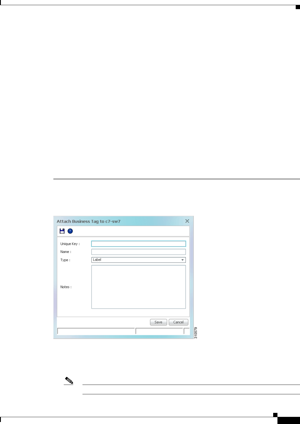
7-3
Cisco Prime Network 4.0 User Guide
OL-29343-01
Chapter 7 Labeling NEs Using Business Tags Attaching and Detaching Business Tags
• Generate a list of business tags.
• Edit the details of a business tag.
• Write business tag notes.
• Remove business tags.
• Create aggregations.
• Export a business tag through a northbound interface.
See the following documents for more information about these features:
• Configuring your system to use Chinese characters— Cisco Prime Network 4.0 Installation Guide.
• Integration over northbound interfaces—Cisco Prime Network 4.0 Integration Developer Guide.
Attaching and Detaching Business Tags
You can attach one business tag for each entity, such as a port or interface. A business tag might identify
a new subscriber to a port, or other information that is relevant in your environment.
To attach a business tag:
Step 1 Right-click the required network object and choose Attach Business Tag. The Attach Business Tag
dialog box is displayed, as shown in Figure 7-1.
Figure 7-1 Attach Business Tag Dialog Box
Step 2 Enter the information for the business tag:
• Unique Key—Enter a unique identifier for the business tag.
• Name—Enter a name for the business tag.
Note Business tag names are case-sensitive.

7-4
Cisco Prime Network 4.0 User Guide OL-29343-01
Chapter 7 Labeling NEs Using Business Tags
Searching for Business Tags and Viewing Their Properties
• Type—Choose the type of business tag: Subscriber, Provider Connection, or Label.
Note If you select Label, the name of the network object changes to display the business tag name
if the Replace name with Business Tag option is selected in the Options dialog box
(Tools > Options). For more information about display options, see Adjusting the Prime
Network Vision GUI Client Settings, page 2-40.
• Notes—(Optional) Enter a free-text message.
Step 3 Click Save. The business tag is attached to the network object and displayed in the Business Tag tab of
the inventory window for the selected network object. The business tag name is also displayed
throughout Cisco Prime Network Vision, such as in the navigation pane, maps, and Cisco PathTracer.
You can search and edit business tag information attached to a network object using tools available from
the appropriate Business Tag dialog box.
To detach a business tag, right-click the network object and choose Detach Business Tag.
Searching for Business Tags and Viewing Their Properties
Cisco Prime Network Vision enables you to find a business tag by entering the full or partial business
tag key, the full or partial business tag, or by specifying a specific type of business tag. In response, the
business tags that meet the search criteria are listed.
If you know the location of the business tag, you can view its properties by opening the Business Tag tab
in the element’s inventory window.
To search for a business tag:
Step 1 Choose Edit > Find Business Tag from the main menu. Figure 7-2 shows an example of the Find
Business Tag dialog box.
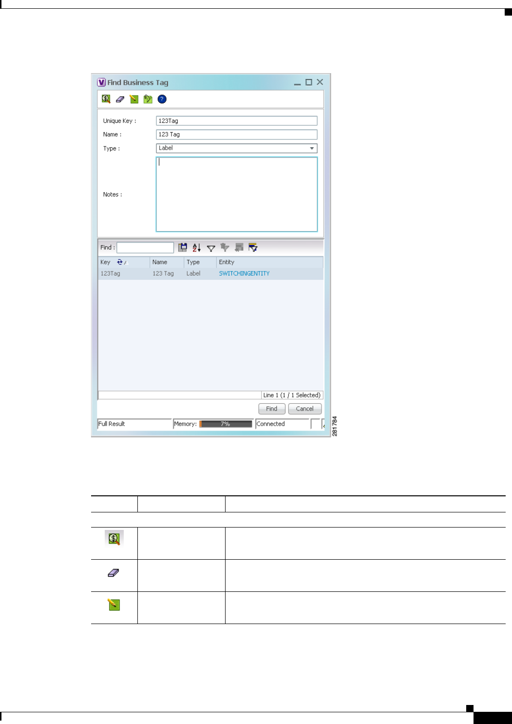
7-5
Cisco Prime Network 4.0 User Guide
OL-29343-01
Chapter 7 Labeling NEs Using Business Tags Searching for Business Tags and Viewing Their Properties
Figure 7-2 Find Business Tag Dialog Box
Table 7-3 describes the fields in the Find Business Tag dialog box.
Table 7-3 Find Business Tag Dialog Box Fields
Icon Name Description
Find Business Tag Finds the business tag according to a name, key, or type entered in
the Find Business Tag dialog box.
Clear Search Clears the search information entered in fields in the Find Business
Tag dialog box.
Edit Business Tag Opens the Edit Business Tag dialog box so you can edit the selected
business tag.

7-6
Cisco Prime Network 4.0 User Guide OL-29343-01
Chapter 7 Labeling NEs Using Business Tags
Searching for Business Tags and Viewing Their Properties
Step 2 Enter the search criteria using the information for the Input Fields in Table 7-3, keeping in mind that the
search function is case-sensitive.
Step 3 Click Find. The search results are displayed in the Results Table at the bottom of the Find Business Tag
dialog box, as shown in Figure 7-2.
Step 4 View additional details as required:
• To view the business tag’s properties, double-click the business tag in the search results table.
• To go to the business tag’s location, click the hyperlink provided in the search results table.
Detach Business
Tag Removes the selected business tag from the element.
Help Displays online help for Cisco Prime Network Vision and
Cisco Prime Network Events.
Input Fields
Unique Key Enter the key you are searching for.
Name Enter a full or partial entry of the name you are searching for.
The search function is case-insensitive, so entering the string
biz tag in the Name field results in business tags with names
containing Biz Tag, Biz tag, and biz tag.
Type From the drop-down list, select the type of business tag you are
searching for: Label, Subscriber, Provider Connection, or All
Types.
Note Enter a full or partial entry of the note for the business tag you are
searching for.
Results Table
Key Business tag key matching the search criteria.
Name Business tag names matching the search criteria.
Type Business tag type matching the search criteria.
Entity Entity to which the business tag is attached, hyperlinked to entity
properties.
Table 7-3 Find Business Tag Dialog Box Fields (continued)
Icon Name Description

7-7
Cisco Prime Network 4.0 User Guide
OL-29343-01
Chapter 7 Labeling NEs Using Business Tags Renaming a Business Element
Renaming a Business Element
The following caveats apply when renaming a business element:
• Except for network VLANs, the original name of the business element is not saved, so you cannot
revert to the original name.
• Renaming a business element affects all users who have the business element loaded in their service
view maps.
To rename business elements in service view maps, right-click the business element and choose
Rename.
Deleting a Business Element
You can delete business elements from the database. However, if you delete a business element from the
database, it can no longer be viewed in Prime Network. We recommend that you delete a business
element only when the physical element no longer exists.
Caution Deleting business elements affects all users who have the business elements loaded in their service view
map.
Table 7-4 lists the requirements that must be met before you can delete a business element.
To delete a business element:
Step 1 Verify that the business element meets all requirements specified in Table 7-4. You cannot delete the
element if all requirements are not met.
Step 2 In the Cisco Prime Network Vision navigation pane or a map, right-click the business element, and
choose Delete.
Step 3 In the confirmation message, click Yes to delete the currently selected element, or click Yes to All to
delete multiple selected elements.
The selected business element is deleted from the business configuration of all users.
Table 7-4 Business Element Deletion Requirements
Business Element Requirements
Layer 2 VPN The Layer 2 VPN has no Logical Circuit Peers (LCPs), or, if it does, the LCPs
display the reconciliation icon.
Layer 3 VPN The VPN has no virtual routers, or, if it does, the virtual routers and sites display
the reconciliation icon.
Site No sites or interfaces are connected or bound to the VRF, or, if they are connected,
they display the reconciliation icon.
Virtual router The virtual router contains no VRFs, sites, or interfaces, or, if it does, the VRFs,
sites, and interfaces display the reconciliation icon.

7-8
Cisco Prime Network 4.0 User Guide OL-29343-01
Chapter 7 Labeling NEs Using Business Tags
Deleting a Business Element

CHAPTER
8-1
Cisco Prime Network 4.0 User Guide
OL-29343-01
8
Tracking Faults Using Prime Network Events
The following topics describe how to use Cisco Prime Network Events (Prime Network Events) to view
and manage faults:
• User Roles Required to Work with Prime Network Events, page 8-1
• Launching Prime Network Events, page 8-1
• Setting Up Your Events View, page 8-2
• Viewing Events and Tickets in Cisco Prime Network Events, page 8-2
• Working with Cisco Prime Network Events, page 8-10
User Roles Required to Work with Prime Network Events
This topic identifies the roles that are required to work with Prime Network Events. Prime Network
determines whether you are authorized to perform a task as follows:
• For GUI-based tasks (tasks that do not affect elements), authorization is based on the default
permission that is assigned to your user account. Only users with the Administrator role can log into
Prime Network Events.
• For element-based tasks (tasks that do affect elements), authorization is based on the default
permission that is assigned to your account. That is, whether the element is in one of your assigned
scopes and whether you meet the minimum security level for that scope.
For more information on user authorization, see the topic on device scopes in the Cisco Prime Network
4.0 Administrator Guide.
Launching Prime Network Events
To launch Prime Network Events, choose Start > Programs > Cisco Prime
Network > gateway IP address > Cisco Prime Network Events, and enter your username and password.
If any client updates are available, Prime Network automatically installs them.
Note If Prime Network is integrated with the suite, launch Prime Network Events from Prime Central. Choose
Assure > Prime Network > Events in the menu bar. The Prime Network Events application is opened
in a separate window.

8-2
Cisco Prime Network 4.0 User Guide OL-29343-01
Chapter 8 Tracking Faults Using Prime Network Events
Setting Up Your Events View
Setting Up Your Events View
The Prime Network Events Options dialog box enables you to change various aspects of the event
display in Prime Network Events. To set up your events view, choose Tools > Options from the main
menu. Table 8-1 lists the available options.
Viewing Events and Tickets in Cisco Prime Network Events
Events are displayed according to event categories, which are represented by tabs in the Cisco Prime
Network Events window. Each tab displays an events list log that provides event information for the
specific event category. Events can be of system type or network type. The Ticket tab displays the tickets
that have been generated for correlated events. Events and tickets are sorted by date, with the latest item
displayed first and the oldest item displayed last.
Table 8-1 Options for Changing Prime Network Events GUI Client
Option Description
Save last filter Saves the filter criteria defined per event type in the Filter Events dialog box. The
filter criteria are available the next time you log into Prime Network Events.
Note Events are not filtered automatically when you next log into Prime
Network Events unless the Open Events with saved filter option is also
selected.
Open
Prime Network
Events with saved
filter
When enabled, applies the previously defined filter to the events as soon as you
log into Prime Network Events. The events are continuously filtered according
to the defined settings, even after you close the application.
Display n records
per page Specifies the number of events to be displayed per page.
Export n records
in total Sets the maximum number of events to be exported to a file.
Run auto refresh
every n secs Automatically refreshes the Prime Network Events display after the specified
number of seconds.
Note This option uses rapid refresh from the database, which can affect the
performance of other vital database options.
Display data for the
last n hours Displays past events from the specified number of hours. Values range from 1 to
336 hours (14 days), with a default of 2 hours.
If you increase the number of hours, it can take longer for the events to be
displayed.
Find mode (No
automatic data
retrieval)
Operates the Prime Network Events window in Find mode. In this mode, no
events will be retrieved from the database when you open the application or
switch between tabs. You can click the Find button in the toolbar to search for
the events you need.
When in Find mode, the status bar in the Prime Network Events window shows
“Find Mode (no automatic data retrieval).”
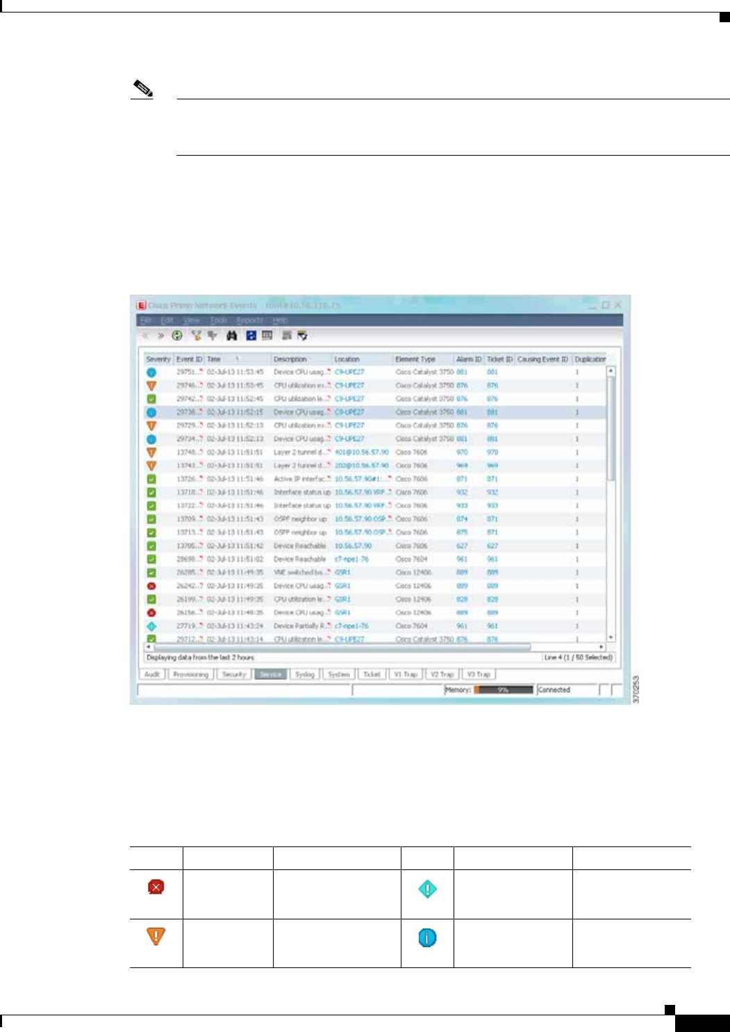
8-3
Cisco Prime Network 4.0 User Guide
OL-29343-01
Chapter 8 Tracking Faults Using Prime Network Events Viewing Events and Tickets in Cisco Prime Network Events
Note Cisco Prime Network Events displays active events only. It does not display events that have
been archived. To see archived events, use Prime Network’s reporting functionality. For more
information, see the Cisco Prime Network Operations Reports User Guide.
Prime Network Events displays events for the last two hours by default. To modify the default number
of hours for which events are displayed, see Setting Up Your Events View, page 8-2. Increasing the
number of hours can affect how long it takes for the events to be displayed.
Figure 8-1 shows an example of the Prime Network Events window.
Figure 8-1 Prime Network Events Window
Event Severity Indicators
The Severity column contains color-coded icons that reflect the severity of the event. An icon appears
for each ticket or event in the Prime Network Events tabs (based on its severity) as shown in Table 8-2.
Table 8-2 Severity Indicators
Icon Color Severity Icon Color Severity
Red Critical Light Blue Warning
Orange Major Medium Blue Information

8-4
Cisco Prime Network 4.0 User Guide OL-29343-01
Chapter 8 Tracking Faults Using Prime Network Events
Viewing Events and Tickets in Cisco Prime Network Events
Event Types and Categories
Events are grouped in tabs according to type. Each tab displays basic information about the events,
including severity, event ID, time, and description. In addition, most event tabs show the Location
parameter, which indicates the entity that triggered the event and is a hyperlink that can be clicked to
access the entity’s properties.
Note Prime Network stores events in the database in Greenwich Mean Time (GMT) format. The Prime
Network client converts events to the time zone that is configured on the client workstation. The
times displayed in the Cisco Prime Network Events GUI reflect the time according to the client
workstation.
The following categories of events can be viewed in Prime Network Events:
• Audit Events, page 8-4
• Provisioning Events, page 8-5
• Security Events, page 8-5
• System Events, page 8-6
• Service Events, page 8-6
• Syslogs, page 8-7
• V1 Traps, page 8-7
• V2 Traps, page 8-8
• V3 Traps, page 8-8
In addition to events, you can also view and manage tickets in Prime Network Events. See Tickets,
page 8-9 for more information.
Audit Events
Events related to all login activity and audit of other activities of the system users. The Audit tab displays
the following parameters that specifically relate to audit events:
Yellow Minor Dark blue Indeterminate
Green Cleared, Normal, or
OK
Table 8-2 Severity Indicators (continued)
Icon Color Severity Icon Color Severity

8-5
Cisco Prime Network 4.0 User Guide
OL-29343-01
Chapter 8 Tracking Faults Using Prime Network Events Viewing Events and Tickets in Cisco Prime Network Events
Provisioning Events
Events displayed in the Provisioning tab are events triggered during the configuration of a device, for
example, execution of a configuration script.
The Provisioning tab displays the following parameters that specifically relate to provisioning events:
Security Events
Security events are related to client login and user activity when managing the system and the
environment.
The Security tab displays the following parameters that specifically relate to security events:
For more information about the system security events displayed in this tab, see Cisco Prime Network
Supported System and Security Events.
Table 8-3 Audit Events
Column Description
Command Name Audit-specific command name, prefaced by, for example, Get, Update,
or Find.
Command Signature Actual command run by Prime Network, such as
GetEventViewerProperties.
Command Parameters Command parameters issued with the command identified in the
Command Name column.
Originating IP IP address of the client that issued the command.
User Name Name of the user who initiated the command.
Table 8-4 Provisioning Events
Column Description
Prime Login Username Username of the logged in user.
VNE Login Username Username that was used to access the device. This field shows “From
VNE Login” except in cases where different device access credentials
were specified when executing a configuration command. ‘From VNE
Login’ means that the username specified when creating the VNE is
being used.
Status Status of the provisioning activity, such as Success or Fail.
Table 8-5 Security Events
Column Description
Username Name of the logged in user.
Originating IP IP address of the client where the event was triggered.

8-6
Cisco Prime Network 4.0 User Guide OL-29343-01
Chapter 8 Tracking Faults Using Prime Network Events
Viewing Events and Tickets in Cisco Prime Network Events
System Events
System events are related to the everyday working of the internal system and its components, such as
alarm thresholds, disk space and AVMs.
The System tab displays the following parameters
For more information about the system error and event messages displayed in this tab, see Cisco Prime
Network 4.0 Supported System and Security Events.
Service Events
Service events are network events such as link down events, adaptive polling events, BGP neighbor loss
events, and so on.
The Service tab displays the following parameters that specifically relate to service events.
For more information about the service alarms that are displayed in this tab, see Cisco Prime Network
4.0 Supported Service Alarms.
Table 8-6 System Tab
Column Description
Severity Icon indicating the severity of the alarm on the event (the color and type
of alarm are displayed in the Properties window Severity field). See
Event Severity Indicators, page 8-3.
Event ID Identifier of the event, assigned sequentially.
Time Date and time when the event happened and was logged and recorded.
Description Description of the event, such as “AVM 77 is shutting down. Unit =
11.22.33.444.”
Location Entity that triggered the event.
Table 8-7 Service Tab
Column Description
Element Type The type of element that triggered the root event, e.g., Cisco 7606.
Alarm ID Hyperlinked identifier of the alarm associated with the event. Click the
link to view the Ticket Properties window.
Ticket ID Hyperlinked identifier of the ticket associated with the event. Click the
link to view the Ticket Properties window.
Causing Event ID Identifier of the causing event.
Duplication Count For network events, the duplication count is calculated by the VNE and
pertains only to flapping events. The duplication count represents the
number of noncleared events aggregated by the flapping event.
Reduction Count For network events, the reduction count is calculated by the VNE and
pertains only to flapping events. The reduction count represents the
number of events that are aggregated by the flapping event.

8-7
Cisco Prime Network 4.0 User Guide
OL-29343-01
Chapter 8 Tracking Faults Using Prime Network Events Viewing Events and Tickets in Cisco Prime Network Events
Syslogs
Syslogs are received from the devices by the VNEs, and syslog events are generated.
The Syslog tab displays the following parameters that specifically relate to syslog events.
V1 Traps
The V1 Trap tab displays the following parameters that relate specifically to V1 traps:
For more information about traps, see Cisco Prime Network Supported Traps.
Table 8-8 Syslog Tab
Column Description
Element Type The type of element that triggered the root event, e.g., Cisco 7606.
Alarm ID Hyperlinked identifier of the alarm associated with the event. Click the
link to view the Ticket Properties window.
Ticket ID Hyperlinked identifier of the ticket associated with the event. Click the
link to view the Ticket Properties window.
Causing Event ID Identifier of the causing event.
Duplication Count For network events, the duplication count is calculated by the VNE and
pertains only to flapping events. The duplication count represents the
number of noncleared events aggregated by the flapping event.
Reduction Count For network events, the reduction count is calculated by the VNE and
pertains only to flapping events. The reduction count represents the
number of events that are aggregated by the flapping event.
Table 8-9 V1 Trap Tab
Column Description
Element Type The type of element that triggered the root event, e.g., Cisco 7606.
Alarm ID Identifier of the alarm associated with the event, hyperlinked to the
Alarm Properties window.
Ticket ID Hyperlinked sequential identifier of the ticket. Click the link to view the
Ticket Properties window.
Causing Event ID Identifier of the causing event, hyperlinked to the Network Event
Properties window.
Duplication Count For network events, the duplication count is calculated by the VNE and
pertains only to flapping events. The duplication count represents the
number of noncleared events aggregated by the flapping event.
Reduction Count For network events, the reduction count is calculated by the VNE and
pertains only to flapping events. The reduction count represents the
number of events that are aggregated by the flapping event.

8-8
Cisco Prime Network 4.0 User Guide OL-29343-01
Chapter 8 Tracking Faults Using Prime Network Events
Viewing Events and Tickets in Cisco Prime Network Events
V2 Traps
The V2 Trap tab displays the following parameters that relate specifically to V2 traps:
For more information about the Cisco IOS and Cisco IOX traps displayed in this tab, see Cisco Prime
Network Supported Traps.
V3 Traps
The V3 Trap tab displays the following parameters that relate specifically to V3 traps:
Table 8-10 V2 Trap Tab
Column Description
Element Type The type of element that triggered the root event, e.g., Cisco 7606.
Alarm ID Identifier of the alarm associated with the event, hyperlinked to the
Alarm Properties window.
Ticket ID Sequential identifier of the ticket, hyperlinked to the Ticket Properties
window.
Causing Event ID Identifier of the causing event, hyperlinked to the Network Event
Properties window.
Duplication Count For network events, the duplication count is calculated by the VNE and
pertains only to flapping events. The duplication count represents the
number of noncleared events aggregated by the flapping event.
Reduction Count For network events, the reduction count is calculated by the VNE and
pertains only to flapping events. The reduction count represents the
number of events that are aggregated by the flapping event.
Table 8-11 V3 Trap Tab
Column Description
Severity Icon indicating the severity of the alarm on the event (the color and type
of alarm are displayed in the Properties window Severity field). See
Event Severity Indicators, page 8-3.
Event ID Calculated correlation identifier.
Time Date and time when the event happened and was logged and recorded.
Description Description of the event, such as “Enterprise generic trap.”
Location Hyperlink to the entity that triggered the trap.
Element Type The type of element that triggered the root event, e.g., Cisco 7606.
Alarm ID Identifier of the alarm associated with the event, hyperlinked to the
Alarm Properties window.
Ticket ID Sequential identifier of the ticket, hyperlinked to the Ticket Properties
window.
Causing Event ID Identifier of the causing event, hyperlinked to the Network Event
Properties window.

8-9
Cisco Prime Network 4.0 User Guide
OL-29343-01
Chapter 8 Tracking Faults Using Prime Network Events Viewing Events and Tickets in Cisco Prime Network Events
For more information about the Cisco IOS and Cisco IOX traps displayed in this tab, see Cisco Prime
Network 4.0 Supported Traps.
Tickets
The Ticket tab displays detailed information specific to tickets. For information about viewing and
managing tickets in Prime Network Vision, see Working with Tickets in Prime Network Vision,
page 9-1.
Table 8-12 describes the information that is displayed in the Ticket tab.
Duplication Count For network events, the duplication count is calculated by the VNE and
pertains only to flapping events. The duplication count represents the
number of noncleared events aggregated by the flapping event.
Reduction Count For network events, the reduction count is calculated by the VNE and
pertains only to flapping events. The reduction count represents the
number of events that are aggregated by the flapping event.
Trap Type OID Trap object identifier.
Translated Enterprise Translation of the OID using the MIB. For example, an enterprise OID
of .1.3.6.1.2.1.88.2 is displayed in this column as
.iso.org.dod.internet.mgmt.mib-2.dismanEventMIB.dismanEventMIB
NotificationPrefix.
Enterprise Enterprise OID for the trap, representing the company or organization
that is associated with the trap.
Table 8-11 V3 Trap Tab (continued)
Column Description
Table 8-12 Ticket Tab
Column Description
Severity Icon indicating the severity of the alarm on the ticket (the color and type
of alarm are displayed in the Ticket Properties window Severity field).
See Event Severity Indicators, page 8-3.
Ticket ID Sequentially assigned identifier of the ticket, hyperlinked to the Ticket
Properties window.
Notes An icon in this column indicates that a note has been added for the ticket.
Click on the icon to read the note and add your own note, if necessary.
Last Modification Time Date and time (per the database) that the ticket was last updated.
Updates can result from either manual or automatic operations.
Root Event Time Date and time that the event that created the root cause alarm of the
ticket was detected.
Description Description of the event, such as “Layer 2 tunnel down.”
Location Hyperlink to the entity that triggered the event.
Element Type The type of element that triggered the root event, e.g., Cisco 7606.

8-10
Cisco Prime Network 4.0 User Guide OL-29343-01
Chapter 8 Tracking Faults Using Prime Network Events
Working with Cisco Prime Network Events
For information about viewing ticket properties, see Viewing Ticket Properties, page 8-14.
Working with Cisco Prime Network Events
The following topics describe how to view, filter, and display the properties of specific events and
tickets, and how to refresh and export events:
• Viewing Event Properties, page 8-10
• Viewing Ticket Properties, page 8-14
• Refreshing Cisco Prime Network Events Information, page 8-17
• Filtering Events, page 8-18
• Exporting Displayed Data, page 8-21
Viewing Event Properties
Cisco Prime Network Events enables you to view the properties of a specific event type. The Event
Properties window displays detailed information about the event; for example, the severity and the
number of affected parties.
Tip Clicking the Details tab on the Event Properties window displays the properties of the selected ticket or
event in the Properties pane.
Acknowledged Whether the ticket is acknowledged or has been modified: Yes, No, or
Modified. If a ticket changes after it has been acknowledged, it is
marked as Modified. If an acknowledged ticket is deacknowledged, the
status changes from Yes to No in this column.
Creation Time Date and time that the ticket was created.
Event Count Number of events associated with the ticket.
Affected Devices Count Number of devices affected by the ticket (the sources of the alarm and
their subsequent alarms).
Duplication Count For tickets, the duplication count is the sum of the duplication counts of
all events that are associated with the root alarm.
Reduction Count Ticket reduction count is the sum of reduction counts of all the events
that are associated to the ticket. The History tab in the Ticket Properties
window displays one reduction count for each event listed. For more
information, see Chapter 9, “Working with Tickets in Prime Network
Vision.”
Alarm Count Total number of alarms associated with the ticket, including the root
alarm.
Table 8-12 Ticket Tab (continued)
Column Description
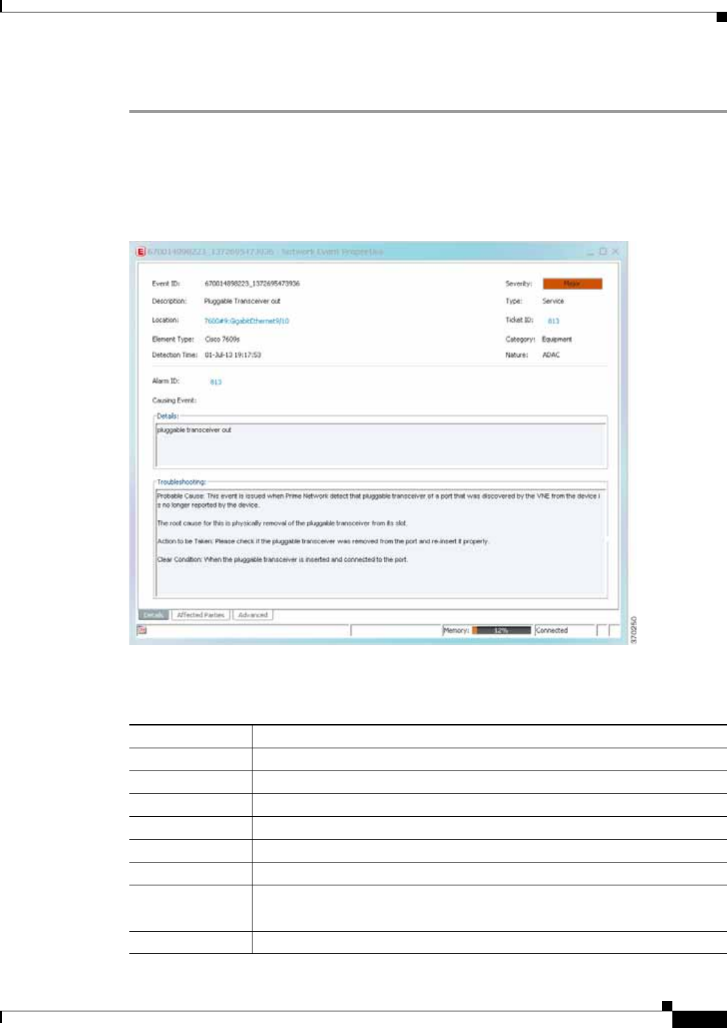
8-11
Cisco Prime Network 4.0 User Guide
OL-29343-01
Chapter 8 Tracking Faults Using Prime Network Events Working with Cisco Prime Network Events
To view event properties:
Step 1 Select the required tab for the specific event type.
Step 2 Select an event and choose View > Properties from the main menu. The event properties are displayed
for the selected event, either in the lower portion of the Cisco Prime Network Events window or in a
separate window as shown in Figure 8-2. The Details tab is displayed by default.
Figure 8-2 Network Event Properties Window - Details Tab
Table 8-13 describes the information that is displayed in the Details tab in the Event Properties window.
Table 8-13 Details Tab for Events
Field Description
Event ID Unique identifier for the selected event.
Severity Severity of the event, indicated by color and text label.
Description Description of the event.
Type Type of event, such as Security or Service.
Location Entity that triggered the event, hyperlinked to its entry in inventory.
Element Type The type of device that triggered the event, e.g., Cisco 7609
Ticket ID This field is displayed only for network events.
Sequential identifier of the ticket, hyperlinked to the Ticket Properties window.
Detection Time Date and time when the event happened and was logged and recorded.

8-12
Cisco Prime Network 4.0 User Guide OL-29343-01
Chapter 8 Tracking Faults Using Prime Network Events
Working with Cisco Prime Network Events
Step 3 You can view additional properties in the following tabs:
• Advanced tab—See Table 8-14.
• Affected Parties tab—See Table 9-7.
• Audit tab—See Table 8-15.
• Provisioning tab—See Table 8-16.
• Security tab—See Table 8-17.
• Trap tab—See Table 8-18.
The tabs that are displayed depend on the type of event, such as a Service event or a Provisioning event.
Device Time The time zone of the device.
Note This information is available only for Cisco ASR5000 devices.
Category The category of the fault, which can be any one of the following:
• Communications—Associated with procedures and/or processes required to
convey information from one point to another.
• Quality of Service—Associated with a degradation in the quality of service.
• Processing error—Associated with a software or processing fault equipment.
• Environmental—Associated with a condition relating to an enclosure in
which the equipment resides.
• Equipment—Associated with an equipment fault.
• Undetermined—Not categorized.
Nature The nature of the fault, which can be one of the following:
• ADAC (Automatically Detected Automatically Cleared)—When the clearing
is automatically detected and cleared by Element Management System
(EMS). For example, Link Down.
• ADMC (Automatically Detected Manually Cleared)—When clearing
requires manual intervention. For example, DWDM Fatal Error syslog.
Alarm ID This field is displayed only for network events.
Alarm identifier, hyperlinked to the Ticket Properties window or the Alarm
Properties window.
Causing Event This field is displayed only for network events.
The identifier of the causing event.
Details Detailed description of the event.
Troubleshooting The probable cause of the event, action to be taken to rectify the problem, and the
clearing condition.
Note This information is available only for service events and Cisco ASR5000
traps.
Table 8-13 Details Tab for Events (continued)
Field Description

8-13
Cisco Prime Network 4.0 User Guide
OL-29343-01
Chapter 8 Tracking Faults Using Prime Network Events Working with Cisco Prime Network Events
Table 8-14 Advanced Tab
Field Description
Duplication Count For network events, the duplication count is calculated by the VNE and
pertains only to flapping events. The duplication count represents the
number of noncleared events aggregated by the flapping event.
Reduction Count For network events, the reduction count is calculated by the VNE and
pertains only to flapping events. The reduction count represents the number
of events that are aggregated by the flapping event.
Affected Devices The number of devices affected by the ticket.
Alarm Count The total number of alarms associated with the ticket, including the root
alarm.
Table 8-15 Audit Tab
Field Description
User Name Name of user who initiated the command.
Result Command result, if available.
Originating IP IP address of the client that issued the command.
Command Signature Actual command run by Prime Network, such as
GetEventViewerProperties.
Command Parameters Parameters applied to the command.
Table 8-16 Provisioning Tab
Field Description
User Name Name of the user who performed the provisioning operation.
Status Status of the operation: Success or Fail.
Table 8-17 Security Tab
Field Description
User Name Name of the user who triggered the event.
Client Type Client that triggered the event: Cisco Prime Network Vision, Cisco Prime
Network Administration, Cisco Prime Network Events, or Unknown.
Originating IP IP address of the client where the event was triggered.

8-14
Cisco Prime Network 4.0 User Guide OL-29343-01
Chapter 8 Tracking Faults Using Prime Network Events
Working with Cisco Prime Network Events
The properties of a selected ticket can be viewed in the Ticket Properties window. For a detailed
description of the Ticket tab properties, see Viewing Ticket Properties, page 8-14.
Viewing Ticket Properties
You can view the properties of a selected ticket in Cisco Prime Network Events by displaying the Ticket
Properties window. To view ticket properties in Cisco Prime Network Events:
Step 1 In the Ticket tab in the Cisco Prime Network Events window, select the required ticket.
Step 2 Choose View > Properties from the main menu. The properties are displayed for the selected ticket,
either in the lower portion of the Cisco Prime Network Events window or in a separate window as shown
in Figure 8-3.
Table 8-18 Trap Tab
Field Description
Version SNMP version: version-1, version-2c, or version-3.
Community String Community that the device sends in the Protocol Data Unit (PDU).
Error Status Error status: No Error, Too Big, No Such Name, Bad Value, Read Only, and
Gen Err.
Values Table
Translated OID String representation of the OID. For example, 1.3.6 is translated into
iso.org.dod where:
• 1 represents iso.
• 3 represents org.
• 6 represents dod.
Translated Value String representation of the OID value. For example, 1.3 is translated to
iso(1).org.10, or a specific value, such as “down” or “4 days, 20 hours, 32
minutes, 11 seconds.”
OID OID that is not translated. It is a dot notation representation of the OID, such
as 1.3.6.1.4.1.9.
Value Value that is not translated.
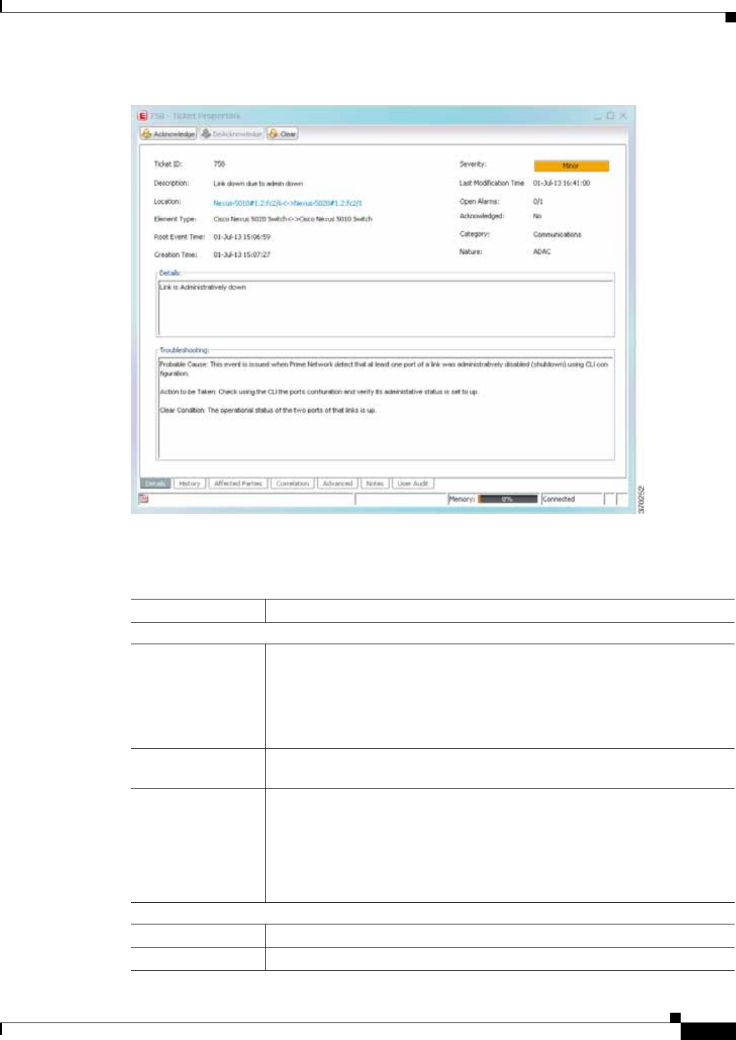
8-15
Cisco Prime Network 4.0 User Guide
OL-29343-01
Chapter 8 Tracking Faults Using Prime Network Events Working with Cisco Prime Network Events
Figure 8-3 Ticket Properties Window - Details Tab
Table 8-19 describes the information that is displayed in the Details tab in the Ticket Properties window.
Table 8-19 Ticket Properties Window - Details Tab
Field Description
Buttons
Acknowledge Acknowledges that the ticket is being handled. For more information, see
Acknowledging/Deacknowledging a Ticket, page 9-15.
If a ticket is acknowledged, and events are correlated to it after correlation, the
ticket is considered to have not been acknowledged.
This button is enabled only if the ticket is not acknowledged.
DeAcknowledge A ticket that has been acknowledged can be deacknowledged, indicating that it
still needs to be handled.
Clear Requests the Prime Network system to remove the faulty network element from
the Prime Network networking inventory. In addition, it sets the ticket to
Cleared severity or status and automatically changes the acknowledged status
of the ticket to Yes. For more information, see Clearing a Ticket, page 9-15.
This button is enabled only if the severity of the alarm is higher than Cleared
or Normal.
Details Tab
Ticket ID Sequentially assigned identifier of the ticket.
Severity Severity of the ticket, indicated by color and text label.

8-16
Cisco Prime Network 4.0 User Guide OL-29343-01
Chapter 8 Tracking Faults Using Prime Network Events
Working with Cisco Prime Network Events
Description Description of the ticket.
Last Modification
Time Date and time (per the database) that the ticket was last updated. Updates can
result from either manual or automatic operations.
Location Hyperlink to the entity that triggered the event.
Note If the entity that triggered the event is outside your scope, a message is
displayed that states you do not have permission to access the selected
item.
Open Alarms Number of open alarms out of all alarms, such as 3/4.
Element Type The type of device that triggered the root event.
Root Event Time Date and time that the event that created the root cause alarm of the ticket was
detected.
Acknowledged Whether or not the ticket has been acknowledged: Yes or No.
Creation Time Date and time when the ticket was created.
Device Time The time zone of the device.
Note This information is available only for Cisco ASR5000 devices.
Category The category of the fault, which can be any one of the following:
• Communications—Associated with procedures and/or processes required
to convey information from one point to another.
• Quality of Service—Associated with a degradation in the quality of
service.
• Processing error—Associated with a software or processing fault
equipment.
• Environmental—Associated with a condition relating to an enclosure in
which the equipment resides.
• Equipment—Associated with an equipment fault.
• Undetermined—Not categorized.
Nature The nature of the fault, which can be one of the following:
• ADAC (Automatically Detected Automatically Cleared)—When the
clearing is automatically detected and cleared by Element Management
System (EMS). For example, Link Down.
• ADMC (Automatically Detected Manually Cleared)—When clearing
requires manual intervention. For example, DWDM Fatal Error syslog.
Details Detailed description of the ticket.
Troubleshooting The probable cause of the last event in the root alarm, the action to be taken to
rectify the problem and the clearing condition.
Note This information is available only for service events and
Cisco ASR5000 traps.
Table 8-19 Ticket Properties Window - Details Tab (continued)
Field Description

8-17
Cisco Prime Network 4.0 User Guide
OL-29343-01
Chapter 8 Tracking Faults Using Prime Network Events Working with Cisco Prime Network Events
Step 3 As required, review additional properties for the ticket. Table 8-20 identifies the additional tabs that are
displayed in the Ticket Properties window and links to the relevant information.
Refreshing Cisco Prime Network Events Information
Cisco Prime Network Events displays current information in lists in each tab. While you view a list, the
information is not updated unless you manually refresh the list or activate autorefresh. The default
autorefresh setting is 60 seconds and can be adjusted (see Adjusting the Prime Network Vision GUI
Client Settings, page 2-40). Your filter settings remain intact.
Table 8-20 Ticket Properties Window - Additional Tabs
Tab Description
History Contains the history of the ticket, including all the events. For more information, see
History Tab, page 9-11.
Affected Parties The services (affected pairs) that are potentially affected (potential impact analysis)
by the ticket. For more information, see Affected Parties Tab, page 9-11.
Correlation Displays all alarms that are correlated to the selected ticket. For more information,
see Correlation Tab, page 9-13.
Advanced The number of affected devices, correlations, duplications, and reductions for the
selected ticket. In addition, it provides any other additional information available
about the ticket. For more information, see Advanced Tab, page 9-13.
Notes Enables you to add and save notes for the selected ticket. The Notes tab is not
available for tickets that have been archived. For more information, see Notes Tab,
page 9-14.
User Audit Enables you to see which ticket-related actions were carried out by which users, and
when the action took place. For more information, see User Audit Tab, page 9-14.

8-18
Cisco Prime Network 4.0 User Guide OL-29343-01
Chapter 8 Tracking Faults Using Prime Network Events
Working with Cisco Prime Network Events
Table 8-21 shows the refresh buttons.
To manually refresh a list, choose View > Refresh from the main menu. To automatically refresh a list,
click Auto Refresh in the toolbar.
Filtering Events
The Filter Events dialog box allows you to filter events according to a number of criteria including
severity, identifier, time stamp, description, location, and category-specific information.
You may also use the filter to search for information in the database.
The Filter icon toggles to indicate that a filter has been applied.
The following settings in the Cisco Prime Network Events Options dialog box also affect your filters:
• If you check the Keep Last Filter check box, the currently defined filter settings are saved in the
registry and are displayed the next time you log in, but are not applied.
• If you check the Open Using Filter check box, the events are continuously filtered according to the
defined settings, even when you log out of and back into the application.
For more information, see Adjusting the Prime Network Vision GUI Client Settings, page 2-40.
See the following topics for more information about filtering events:
• Defining Filters, page 8-19
• Removing Filters, page 8-20
For information about filtering tickets, see Filtering Tickets by Criteria, page 9-7.
Table 8-21 Cisco Prime Network Events Refresh Buttons
Button Name Function
Refresh Now Manually refreshes the events list.
Auto Refresh Automatically refreshes the events list. The Auto Refresh icon toggles to
indicate whether auto refresh is on or off. This icon indicates auto refresh
is on.
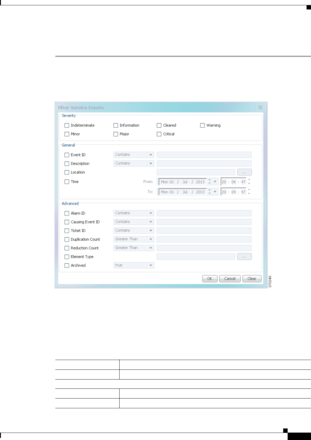
8-19
Cisco Prime Network 4.0 User Guide
OL-29343-01
Chapter 8 Tracking Faults Using Prime Network Events Working with Cisco Prime Network Events
Defining Filters
To define a filter:
Step 1 Choose Edit > Filter from the main menu. The criteria that you can use for filtering differs for events
and tickets. For example, Figure 8-4 shows the Filter Events dialog box for service events. For an
example of the Ticket Filter dialog box, see Figure 9-2.
Figure 8-4 Filter Events Dialog Box - Service Events
Step 2 Specify the filter criteria by using the following steps and the information in Table 8-22:
a. Check the check box for each criterion to use for filtering.
b. As needed, choose the operator for the filter, such as Contains or Does Not Contain.
c. Supply the specific information to apply to the filter, such as the time, a string, or one or more IP
addresses.
Table 8-22 Cisco Prime Network Events Filter Events Options
Field Description
Severity Severities to be included in the filter.
General
Event ID Event identifier to apply to the filter.
Description String to include or exclude.

8-20
Cisco Prime Network 4.0 User Guide OL-29343-01
Chapter 8 Tracking Faults Using Prime Network Events
Working with Cisco Prime Network Events
Step 3 Click OK to save your filter settings and apply the filter. The filtered entries are displayed in the list
according to the defined criteria.
Removing Filters
To remove a filter:
Step 1 Click Filter in the main toolbar.
Step 2 In the Filter Events dialog box, click Clear. The selected options in the Filter Events dialog box are
cleared.
Step 3 Click OK. All events are displayed in the list.
Location Network elements to include.
This field is not displayed for Audit events.
Time Beginning and ending dates and times to apply to the filter.
Network Events Advanced Options
Alarm ID Alarm identifier to apply to the filter.
Causing Event ID Identifier of the causing event to apply to the filter.
Ticket ID Ticket identifier to apply to the filter.
Duplication Count Duplication count value to use for filtering.
Reduction Count Reduction count value to use for filtering.
Element Type Filter by the type of element that triggered the event.
Archived Archive status to use for filtering: True or False.
System Events Advanced Options
Command Name String in the command name to use for filtering.
Command Signature String in the command signature to use for filtering.
Command Parameters String in a command parameter to use for filtering.
Originating IP Originating IP address to include or exclude from filtering.
Status Status to use for filtering: Configuring, Fail, Success, or Unknown.
User Name String in the username to use for filtering.
Table 8-22 Cisco Prime Network Events Filter Events Options (continued)
Field Description

8-21
Cisco Prime Network 4.0 User Guide
OL-29343-01
Chapter 8 Tracking Faults Using Prime Network Events Working with Cisco Prime Network Events
Exporting Displayed Data
Cisco Prime Network Events enables you to export the currently displayed data from the Cisco Prime
Network Events table according to the criteria defined in the Cisco Prime Network Events Options
dialog box. You can then import and view at a later time.
To export a table to a file:
Step 1 Choose File > Export.
Step 2 In the Export Table to File dialog box, browse to the directory where you want to save the list.
Step 3 In the File name field, enter a name for the list.
Step 4 Click Save. The displayed events list or rows are saved in the selected directory.

8-22
Cisco Prime Network 4.0 User Guide OL-29343-01
Chapter 8 Tracking Faults Using Prime Network Events
Working with Cisco Prime Network Events

CHAPTER
9-1
Cisco Prime Network 4.0 User Guide
OL-29343-01
9
Working with Tickets in Prime Network Vision
These topics describe how to work with tickets in Prime Network Vision:
• What are Tickets?, page 9-1
• User Roles Required to Work with Tickets in Prime Network Vision, page 9-2
• Viewing Tickets and Network Events for Elements in a Map, page 9-3
• Viewing Ticket Properties, page 9-9
• Managing Tickets, page 9-15
• Impact Analysis in Prime Network, page 9-17
What are Tickets?
A ticket represents the complete hierarchy of correlated alarms representing a single specific fault
scenario. A ticket points to the root cause alarm that is the top-most alarm in the correlation hierarchy.
Examples of alarms are Link Down, Device Unreachable, or Module Out. Some event types are capable
of creating tickets. When an event is generated, it is correlated to an existing event, which is correlated
to a ticket. If there is no existing ticket, a new ticket is created.
Prime Network identifies the relationship between a root cause alarm and its consequent alarms. It
automatically correlates the consequent alarms as children of the root alarm. The ticket pane displays
the ticket (the root cause alarm), the aggregated severity of the ticket, and the severity of the root cause
alarm. The root cause alarm severity is the top-most severity of its contained alarms. In addition, the
ticket pane displays the time at which the original event was detected, the ticket creation time, and a
description of the event that caused the ticket creation.

9-2
Cisco Prime Network 4.0 User Guide OL-29343-01
Chapter 9 Working with Tickets in Prime Network Vision
User Roles Required to Work with Tickets in Prime Network Vision
User Roles Required to Work with Tickets in Prime Network
Vision
This topic identifies the roles that are required to work with tickets in Prime Network Vision. Prime
Network determines whether you are authorized to perform a task as follows:
• For GUI-based tasks (tasks that do not affect elements), authorization is based on the default
permission that is assigned to your user account.
• For element-based tasks (tasks that do affect elements), authorization is based on the default
permission that is assigned to your account. That is, whether the element is in one of your assigned
scopes and whether you meet the minimum security level for that scope.
For more information on user authorization, see the topic on device scopes in the Cisco Prime Network
4.0 Administrator Guide.
The following conditions apply when working with tickets in Prime Network Vision:
• If an element that is outside of your scope is the root cause of a ticket that affects an element in your
scope, you can view the ticket in Prime Network Vision, but you will not be able to:
–
View inventory by clicking the Location hyperlink.
–
Acknowledge, deacknowledge, clear, add note, or remove the ticket.
• You can acknowledge, deacknowledge, clear, remove, or add notes for a ticket only if you have
OperatorPlus or higher permission for the element that holds the root alarm for that ticket.
• If the source or contained sources of the ticket are not in your scope, you cannot view the ticket in
the ticket table, view ticket properties, or perform actions on the ticket.
• If the ticket contains a source that is in your scope, but the source is not the root cause, you can view
the ticket in the ticket table and view ticket properties, but you cannot perform actions on the ticket.
• If the source of the ticket is in your scope, you can view the ticket in the ticket table, view ticket
properties, filter tickets, and perform actions on the ticket.
• By default, users with the Administrator role have access to all managed elements and can perform
any action on tickets. To change the Administrator user scope, see the topic on device scopes in the
Cisco Prime Network 4.0 Administrator Guide.
Table 9-1 identifies the roles required to perform the high level tasks:
Table 9-1 Default Roles/Permissions Required for Working with Tickets in Prime Network
Vision
Task Viewer Operator OperatorPlus Configurator Administrator
Acknowledge/deackno
wledge tickets ——X
1XX
Add notes to a ticket — — X1XX
Clear and remove
tickets ——X
1XX
Clear tickets — — X1XX
Filter tickets X X X X X
Find affected elements X X X X X
Remove tickets — — X1XX

9-3
Cisco Prime Network 4.0 User Guide
OL-29343-01
Chapter 9 Working with Tickets in Prime Network Vision Viewing Tickets and Network Events for Elements in a Map
Viewing Tickets and Network Events for Elements in a Map
The ticket pane, located below the navigation and content panes in the Prime Network Vision window,
displays tickets and network events specific to the elements in the currently displayed map (see
Figure 9-1). You can view or hide the ticket pane by clicking the arrows displayed below the navigation
pane.
The ticket pane contains two tabs:
• Tickets tab—Lists all the tickets relevant to the elements in the map and allows you to manage them.
See Managing Tickets in the Tickets Tab, page 9-4 for details of the information displayed and the
actions available from the Tickets tab.
• Latest Events tab:
–
Lists network events that were created for the elements in the map from the time the map was
opened.
–
Shows network events that Prime Network recognizes and is able to process (actionable events).
Some of these events might be correlated into tickets.
–
An hourglass in the Status column indicates that processing of the event is in progress. A check
mark indicates that the event has been processed.
–
If an event has been correlated into a ticket, the ticket ID will appear in the table and you can
click the link to access the ticket properties.
–
Events are removed from the Latest Events tab after 6 hours or when a maximum of 15000
events is reached, in which case the oldest events are removed first.
View ticket properties X X X X X
View tickets X X X X X
1. In addition, the security level for the device scope must be OperatorPlus or higher for the device that holds the root alarm for
a ticket.
Table 9-1 Default Roles/Permissions Required for Working with Tickets in Prime Network Vision
(continued)
Task Viewer Operator OperatorPlus Configurator Administrator
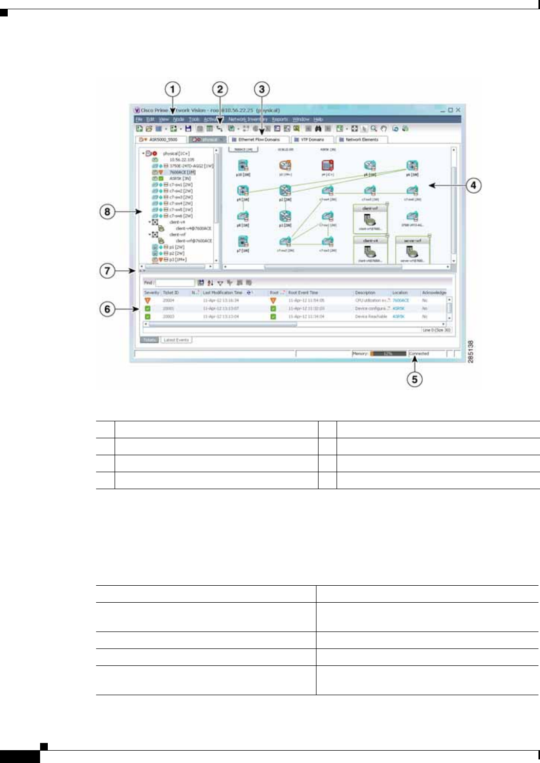
9-4
Cisco Prime Network 4.0 User Guide OL-29343-01
Chapter 9 Working with Tickets in Prime Network Vision
Viewing Tickets and Network Events for Elements in a Map
Figure 9-1 Prime Network Vision Window
Managing Tickets in the Tickets Tab
Table 9-2 describes the functions that are available from the Tickets tab in the ticket pane.
1Menu bar 5Status bar
2Toolbar 6Ticket pane
3Inventory and map tabs 7Hide/Display ticket pane
4Content pane 8Navigation pane
Table 9-2 Ticket Pane Available Functions
Function Related Documentation
Acknowledge a ticket. Acknowledging/Deacknowledging a Ticket,
page 9-15
Clear a ticket. Clearing a Ticket, page 9-15
Clear and remove a ticket. Clearing and Removing Tickets, page 9-16
Filter and view all tickets that meet specific
criteria. Filtering Tickets by Criteria, page 9-7

9-5
Cisco Prime Network 4.0 User Guide
OL-29343-01
Chapter 9 Working with Tickets in Prime Network Vision Viewing Tickets and Network Events for Elements in a Map
Table 9-3 describes the information displayed in the ticket pane.
Locate the elements or links affected by the ticket
in the map or links view. Finding Affected Elements, page 9-15
Remove a ticket. Removing a Ticket, page 9-16
View all tickets or only the filtered tickets of a
selected element. Filtering Tickets by Network Element, page 9-6
View tickets. Viewing Tickets and Network Events for Elements
in a Map, page 9-3
View ticket properties, including the history,
correlated alarms, severity of the root cause
alarm, and affected parties.
Viewing Ticket Properties, page 9-9
Table 9-2 Ticket Pane Available Functions (continued)
Function Related Documentation
Table 9-3 Ticket Information Displayed in the Ticket Pane
Field Name Description
Severity Severity of alarm, represented by an icon. The icon and its color indicate the
alarm severity and thereby the impact of the alarm on the network. For more
information about severity, see Map View, page 2-8.
• Red—Critical
• Orange—Major
• Yellow—Minor
• Light Blue—Warning
• Green—Cleared
• Medium Blue—Informational
• Dark Blue—Indeterminate
Ticket ID Ticket identifier, assigned sequentially. Click the hyperlinked entry to view ticket
properties, and to acknowledge, clear, or refresh the ticket. For more
information, see Chapter 9, “Working with Tickets in Prime Network Vision.”
Notes An icon in this column indicates that a note has been added for the ticket. Click
on the icon to read the note and add your own note, if necessary.
Last Modification
Time Date and time (per the database) that the ticket was last updated. Updates can
result from either manual or automatic operations.
Root Cause Severity of the root cause alarm, represented by a bell icon. The color indicates
the severity of the root cause alarm, as described in the Severity field.
Root Event Time Date and time that the event that created the root cause alarm of the ticket was
detected.
Description Description of the event that caused the ticket creation.
Location Entity that triggered the ticket, as a hyperlink that displays the relevant location
in the inventory.
Element Type The type of element that triggered the root event, e.g., Cisco 7606.

9-6
Cisco Prime Network 4.0 User Guide OL-29343-01
Chapter 9 Working with Tickets in Prime Network Vision
Viewing Tickets and Network Events for Elements in a Map
The ticket details in the ticket pane change automatically as new information arrives. For example, Port
Down is updated to Port Up.
By default, the tickets in the ticket pane are sorted according to the last modification time.
The Find field enables you to search for information in the ticket pane table according to the selected
column. For more information about the buttons displayed in Prime Network Vision tables and table
functionality, see Filtering and Sorting Tabular Content, page 2-42.
Filtering Tickets by Network Element
Prime Network Vision enables you to filter the tickets that are shown in the ticket pane so that you see
only the tickets that have the selected network element as the root cause.
If the selected network element is alarmed due to an operation that occurred on a different VNE, element,
or link, no tickets are displayed.
To view tickets that have a specific network element as the root cause, do either of the following:
• If the network element icon is at the largest size, click the Filter Tickets button.
• Right-click the required network element in the navigation pane or a map and choose Filter Tickets.
In response:
• The ticket pane displays only the tickets that have the selected network element as the root cause.
• The Filter button in the ticket pane toggles to indicate that a filter has been applied.
Click Clear Filter in the ticket pane to view all tickets.
Acknowledged Whether the ticket is acknowledged or has been modified: Yes, No, or Modified.
If the ticket is acknowledged, this field also displays the user who acknowledged
the ticket; for example, Yes(root).
Creation Time Date and time (per the database) that the ticket was created.
Event Count Number of events associated with the ticket.
Affected Devices
Count Number of devices affected by the ticket, including the sources of the alarm and
their subsequent alarms.
Duplication Count For network events, the duplication count is calculated by the VNE and pertains
only to flapping events. The duplication count represents the number of
noncleared events aggregated by the flapping event.
For tickets, the duplication count is the sum of the duplication counts of all
events that are associated with the root alarm.
Reduction Count For network events, the reduction count is calculated by the VNE and pertains
only to flapping events. The reduction count represents the number of events that
are aggregated by the flapping event.
Ticket reduction count is the sum of reduction counts of all the events that are
associated to the ticket. The History tab in the Windows Properties window
displays one reduction count for each event listed.
Alarm Count Total number of alarms associated with the ticket, including the root alarm.
Table 9-3 Ticket Information Displayed in the Ticket Pane (continued)
Field Name Description
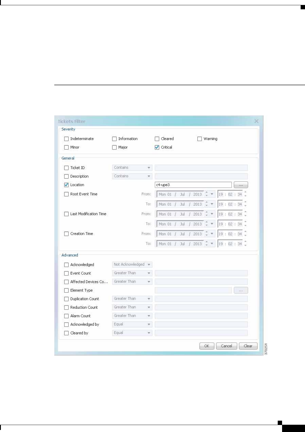
9-7
Cisco Prime Network 4.0 User Guide
OL-29343-01
Chapter 9 Working with Tickets in Prime Network Vision Viewing Tickets and Network Events for Elements in a Map
Filtering Tickets by Criteria
Prime Network Vision enables you to define a filter for the tickets displayed in the ticket pane according
to various criteria. For example, tickets can be filtered according to the number of affected parties or
acknowledged tickets.
To define a ticket filter:
Step 1 Click Ticket Filter in the ticket pane toolbar. The Ticket Filter dialog box is displayed (Figure 9-2).
Figure 9-2 Ticket Filter Dialog Box
Step 2 Specify the filter criteria by using the following steps and the information in Table 9-4:
a. Check the check box for each criterion to use for filtering.
b. As needed, choose the operator for the filter, such as Contains or Does Not Contain.

9-8
Cisco Prime Network 4.0 User Guide OL-29343-01
Chapter 9 Working with Tickets in Prime Network Vision
Viewing Tickets and Network Events for Elements in a Map
c. Supply the specific information to apply to the filter, such as the time, a string, or one or more IP
addresses.
Step 3 Click OK. The tickets are displayed in the ticket pane according to the defined criteria.
Note The Ticket Filter button in the ticket pane toggles to indicate that a filter has been applied.
To remove a ticket filter:
Step 1 Click Ticket Filter in the ticket pane toolbar. The Ticket Filter dialog box is displayed.
Step 2 Click Clear. The selected options in the Ticket Filter dialog box are cleared.
Step 3 Click OK. All the tickets are displayed in the ticket pane.
Table 9-4 Prime Network Ticket Filter Options
Field Description
Severity Severity to be included in the filter.
General
Ticket ID Ticket identifier to be included or excluded when filtering.
Description String in the ticket description to include or exclude.
Location Network elements to include.
Root Event Time Beginning and ending dates and times of the range for the root event time to
apply to the filter.
Last Modification Time Beginning and ending dates and times of the range for the ticket last
modification time to apply to the filter.
Creation Time Beginning and ending dates and times of the range for the ticket creation
time to apply to the filter.
Advanced
Acknowledged Ticket acknowledgement status to include in the filter: Acknowledged, Not
Acknowledged, or Modified.
Event Count Event count value to use for filtering.
Affected Devices Count Number of affected devices to use for filtering.
Element Type Filter by the type of device that triggered the root event.
Duplication Count Duplication count value to use for filtering.
Reduction Count Reduction count value to use for filtering.
Alarm Count Alarm count value to use for filtering.
Archived Archive status to use for filtering: True or False.
Acknowledged By Username of the person who acknowledged the ticket.
Cleared By Username of the person who cleared the ticket.

9-9
Cisco Prime Network 4.0 User Guide
OL-29343-01
Chapter 9 Working with Tickets in Prime Network Vision Viewing Ticket Properties
Viewing Ticket Properties
In Prime Network Vision, open the Ticket Properties window in one of the following ways:
• Open the required map and then double-click the required ticket identifier in the ticket pane.
• Open the required map, right-click a ticket in the ticket pane, and choose Properties.
Figure 9-3 shows the Ticket Properties window.
Figure 9-3 Ticket Properties Window
The information displayed in the Ticket Properties window corresponds with the information displayed
in the Prime Network Vision ticket pane or the Prime Network Vision window. The ID number displayed
in the header corresponds to the ID number of the ticket selected in the ticket pane.
The Ticket Properties window contains the following components:
• Details Tab, page 9-10
• Details Tab, page 9-10
• History Tab, page 9-11
• Affected Parties Tab, page 9-11
• Correlation Tab, page 9-13
• Advanced Tab, page 9-13
• Notes Tab, page 9-14
• User Audit Tab, page 9-14

9-10
Cisco Prime Network 4.0 User Guide OL-29343-01
Chapter 9 Working with Tickets in Prime Network Vision
Viewing Ticket Properties
Details Tab
Table 9-5 describes the information that is displayed in the Details tab about the ticket.
Table 9-5 Event Properties Window - Details Tab
Field Description
Ticket ID Ticket identifier.
Severity Severity propagated from all the correlated alarms.
Description Description of the ticket.
Last Modification Time Date and time (per the database) that the ticket was last updated. Updates can
result from either manual or automatic operations.
Location Entity that triggered the root-cause alarm, as a hyperlink that opens the
relevant location.
Note If the entity that triggered the alarm is outside your scope, a message
is displayed that states you do not have permission to access the
selected item.
Element Type The type of device on which the root event occurred, e.g., Cisco Nexus 5020
Switch
Open Alarms Number of correlated alarms for the ticket that are open, such as 3/4. In this
example, four indicates the total number of correlated alarms for the ticket,
and three indicates the number of alarms that have not been cleared.
Therefore, one alarm has been cleared.
Root Event Time Date and time that the event that created the root cause alarm of the ticket
was detected.
Acknowledged Whether the ticket is acknowledged or has been modified: Yes, No, or
Modified.
If the ticket is acknowledged, this field also displays the user who
acknowledged the alarm; for example, Yes(root).
If a ticket changes after it has been acknowledged, it is marked as Modified.
If an acknowledged ticket is deacknowledged, the status changes from Yes
to No.
Creation Time Date and time the ticket was created.
Details Detailed description of the alarm.
Troubleshooting Provides information about the probable cause of the last event in the root
alarm and the action that should be taken to resolve the problem.
In this release, troubleshooting information is provided for service events
and for traps on ASR 5000 devices only.

9-11
Cisco Prime Network 4.0 User Guide
OL-29343-01
Chapter 9 Working with Tickets in Prime Network Vision Viewing Ticket Properties
History Tab
The History tab enables you to display the history of the ticket, including all the events. Table 9-6
describes the information that is displayed in the History tab.
Affected Parties Tab
The Affected Parties tab displays the service resources (pairs) that are affected by an event, an alarm, or
a ticket. When a fault occurs, Prime Network automatically calculates the affected parties and embeds
this information in the ticket along with all the correlated faults. You can view a list of all the endpoints
that are affected.
The Affected Parties tab displays the service resources (affected pairs) that are affected by the ticket.
The Affected Parties tab contains two tables: Source and Destination. Table 9-7 describes the
information that is displayed in the Affected Properties tab.
Table 9-6 Ticket Properties Window - History Tab
Field Description
Severity Severity bell icon, colored according to the severity of the alarm.
Event ID Event identifier of the specific alarm.
Time Date and time the event was received by the Event Collector.
Description Description of the event.
Location Entity that triggered the alarm, as a hyperlink that opens the relevant
location.
Note If the entity that triggered the alarm is outside your scope, a message
is displayed that states you do not have permission to access the
selected item.
Element Type The type of device on which the root event occurred, e.g., Cisco Nexus 5020
Switch
Alarm ID Alarm identifier.
Ticket ID Ticket identifier.
This field appears in the History tab only in Prime Network Events.
Causing Event ID Identifier of the causing event for the ticket.
Duplication Count For network events, the duplication count is calculated by the VNE and
pertains only to flapping events. The duplication count represents the
number of noncleared events aggregated by the flapping event.
Reduction Count For network events, the reduction count is calculated by the VNE and
pertains only to flapping events. The reduction count represents the number
of events that are aggregated by the flapping event.
Detail panel Long description of the selected event.

9-12
Cisco Prime Network 4.0 User Guide OL-29343-01
Chapter 9 Working with Tickets in Prime Network Vision
Viewing Ticket Properties
When an affected side is selected in the Source table, the Destination table lists all endpoints with
services that have been affected between them and the entry selected in the Source table.
Table 9-7 Ticket Properties Window - Affected Parties Tab
Field Description
Source Table
Location Hyperlinked entry to the port with the affected parties.
Key Unique value taken from the affected element’s business tag key, if it exists.
Name Subinterface (site) name or business tag name of the affected element, if it
exists.
Type Business tag type.
IP Address If the affected element is an IP interface, the IP address of the subinterface
site.
Affected Status (Agg) Status for the affected pair (destination). The same source can be part of
multiple pairs, and therefore each pair can have a different affected status.
The highest affected status reflects the highest among these. The affected
status can be one of the following:
• Potential
• Real
• Recovered
• N/A—From the links view, this indicates Not Applicable.
Destination Table
Location Hyperlinked entry to the port with the affected parties.
Key Unique value taken from the affected element’s business tag key, if it exists.
Name Subinterface name or business tag name of the affected element, if it exists.
Type Business tag type.
IP Address If the affected element is an IP interface, the IP address of the subinterface
site.
Affected Status Status of the affected pair as calculated by the client according to the rules
defined in Status Values for Affected Parties, page 9-17.
Alarm Clear State For each pair, an indication of the clear state of the alarm:
• Cleared—All related alarms for this pair have been cleared.
• Not Cleared—One or more alarms for this pair have not been cleared.

9-13
Cisco Prime Network 4.0 User Guide
OL-29343-01
Chapter 9 Working with Tickets in Prime Network Vision Viewing Ticket Properties
Note The Affected Parties dialog box occasionally displays entries that start with the word Misconfigured.
Entries that start with Misconfigured indicate that the flow has stopped unexpectedly between the source
and destination points. An unexpected termination point can be a routing entity, bridge, or VC switching
entity. The significant aspects of Misconfigured entries are:
• Because the link does not terminate as expected, the link is not actually impacted.
• An error might exist in the configuration or status of the termination points. We recommend that you
check the configuration and status of the affected termination points.
Correlation Tab
The Correlation tab displays all the alarms that are correlated to the selected ticket. Table 9-8 describes
the information that is displayed in the Correlation tab.
Advanced Tab
The Advanced tab displays the following values for the selected ticket:
• Duplication Count:
–
For network events, the duplication count is calculated by the VNE and pertains only to flapping
events. The duplication count represents the number of noncleared events aggregated by the
flapping event.
–
For tickets, the duplication count is the sum of the duplication counts of all events that are
associated with the root alarm.
Table 9-8 Ticket Properties Window - Correlation Tab
Field Description
Alarm Correlation Alarms correlated with the ticket. Expand or collapse the branch to display or
hide information as needed.
The severity displayed is the severity of the root alarm.
Short Description Description of the alarm.
Location Hyperlinked entry that opens an window displaying the selected node along with
the affected parties.
Note If the entity that triggered the alarm is outside your scope, a message is
displayed that states you do not have permission to access the selected
item.
Acknowledged Whether or not the root alarm has been acknowledged: Yes or No.
Last Event Time Date and time the alarm was last modified.
Detail Panel Long description of the selected entry.

9-14
Cisco Prime Network 4.0 User Guide OL-29343-01
Chapter 9 Working with Tickets in Prime Network Vision
Viewing Ticket Properties
• Reduction Count:
–
For network events, the reduction count is calculated by the VNE and pertains only to flapping
events. The reduction count represents the number of events that are aggregated by the flapping
event.
–
For tickets, reduction count is the sum of reduction counts of all the events that are associated
to the ticket. The History tab in the Ticket Properties window displays one reduction count for
each event listed.
• Affected Devices—The number of devices affected by the ticket.
• Alarm Count—The total number of alarms associated with the ticket, including the root alarm.
Notes Tab
The Notes tab enables you to add and save notes for the selected ticket. To add text, enter text in the
Notes field and click Save Notes. The new text is added to any previously existing text.
After you save a note, it appears in the Previous Notes section of the Notes tab, with the name of the user
who added the note and the time it was added. If the user is an external user (for example, a Netcool
user), the username will be displayed in the following format:
“Added by prime-networkUserName (as externalUserName)”
The following restrictions apply to the Notes tab:
• You can add notes for a ticket only if both of the following conditions are true:
–
The default permission for your account is OperatorPlus or higher.
–
The security level for the device scope is OperatorPlus or higher for the device that holds the
root alarm for that ticket.
• The Notes tab is not available for archived tickets.
• The Save Notes button is enabled only when text is entered in the Notes field.
• The text cannot be edited or removed once you have saved the notes.
User Audit Tab
The User Audit tab enables you to see which ticket-related actions were carried out by which users, and
when the action took place.
If the user is an external user (for example, a Netcool user), the username will be displayed in the
following format in the User Name column:
“Added by prime-networkUserName (as externalUserName)”
The following actions are reported in the User Audit tab:
• Acknowledge ticket
• Remove ticket (archive)
• Clear ticket

9-15
Cisco Prime Network 4.0 User Guide
OL-29343-01
Chapter 9 Working with Tickets in Prime Network Vision Managing Tickets
Managing Tickets
The following topics describe how to manage tickets:
• Finding Affected Elements, page 9-15
• Acknowledging/Deacknowledging a Ticket, page 9-15
• Clearing a Ticket, page 9-15
• Removing a Ticket, page 9-16
• Clearing and Removing Tickets, page 9-16
You can acknowledge, clear, remove, or clear and remove a ticket only if both of the following conditions
are true:
• The default permission for your account is OperatorPlus or higher.
• The security level for the device scope is OperatorPlus or higher for the device that holds the root
alarm for that ticket.
Note When Prime Network is in suite mode, the Acknowledge, Deacknowledge, Add Note, Clear, and
Remove functions are disabled.
Finding Affected Elements
To locate elements affected by a ticket in Prime Network Vision, right-click the desired ticket in the
ticket pane and then choose Find Affected Elements.
Depending on the number of affected elements, the results are displayed in one of the following ways:
• If only one element is affected, it is highlighted in the navigation pane and the content area.
• If multiple elements are affected, they are displayed in the Affected Events window.
Acknowledging/Deacknowledging a Ticket
You can acknowledge a ticket to indicate that the ticket is being handled. The change is reported to the
Prime Network gateway and all open Prime Network applications. You can acknowledge multiple tickets
at the same time.
If a new event is correlated to an acknowledged ticket, the ticket status becomes “Modified” and the
ticket must be acknowledged again.
Acknowledged tickets can be manually deacknowledged.
To acknowledge/deacknowledge a ticket, right-click on the ticket and choose
Acknowledge/Deacknowledge.
Clearing a Ticket
You can manually clear tickets when the issues they represent have been addressed. When an open ticket
is cleared, the following operations are performed:
• The ticket is acknowledged.
• All non-cleared alarms associated with the ticket are cleared.
• For tickets relating to physical network elements (e.g., link down, card out), the faulty network
element is removed from the Prime Network inventory.

9-16
Cisco Prime Network 4.0 User Guide OL-29343-01
Chapter 9 Working with Tickets in Prime Network Vision
Managing Tickets
After a ticket is cleared, it remains open for one hour (default) before it is archived. Incoming events can
be correlated to the ticket during this time, effectively re-opening the ticket. An administrator can lock
tickets so that they remain cleared and no new events can be correlated to them. For more information,
see the section, “Changing Oracle Database Fault Settings: Clear, Archive, and Purge Fault Data”, in the
Cisco Prime Network 4.0 Administrator Guide.
To clear one or more tickets, do one of the following:
• Select one or more tickets in the ticket pane, and then right-click and choose Clear.
• Double-click a ticket in the ticket pane and click Clear in the Ticket Properties window.
To clear and remove a ticket at the same time, select Clear and Remove from the right-click menu.
If the system is set to automatically clear tickets, every minute the system scans for tickets that are not
archived, not cleared, and that have not been modified in the last four minutes. If all the ticket’s events
that are not defined as auto-clear are cleared, the system will automatically clear the ticket.
Note If the root cause event is not cleared, the ticket will not be cleared.
Removing a Ticket
Prime Network Vision enables you to completely remove a ticket and all of its active alarms. The ticket
is archived and removed from the ticket pane. The change is reported to the Prime Network gateway and
all instances of Prime Network that are open. Only tickets with a status of Cleared or Information can
be removed.
Note This operation cannot be reversed. A ticket that has been removed can be viewed only by using Prime
Network Events.
When a ticket is removed:
• New alarms that might be related to the ticket, and should therefore be correlated to it, are not
correlated to the original ticket because the ticket has been removed from Prime Network Vision.
• Flagging events that are ticketable open new tickets. The ticket’s events are shown immediately in
the Latest Events tab. The new tickets will be visible in Prime Network Vision two minutes after the
flagging event was created (or up to seven minutes in rare cases).
To remove one or more tickets, select the required tickets in the ticket pane, and then right-click and
choose Remove.
For more information, see Filtering Tickets by Network Element, page 9-6.
Clearing and Removing Tickets
Clearing and removing a ticket:
• Approves the reported faulty ticket.
• Clears the faulty networking entity from Prime Network Vision.
• Archives the ticket.
You can clear and remove multiple tickets at the same time. This operation will attempt to modify any
ticket which is not being used by other processes, such as a ticket that is being updated with new network
events. In order to clear and remove a highly active ticket, you should select only that ticket. That way,
the system will wait until it becomes available for an update before removing it.

9-17
Cisco Prime Network 4.0 User Guide
OL-29343-01
Chapter 9 Working with Tickets in Prime Network Vision Impact Analysis in Prime Network
To clear and remove one or more tickets, select the required tickets in the ticket pane, and then right-click
and choose Clear and Remove.
Note When Prime Network detects a large ticket (with more than 150 associated events), a system event is
generated requesting the administrator to clear and remove the ticket. If this is not done within 15
minutes, the ticket will be automatically archived. A new ticket will be opened for any additional related
incoming events.
Impact Analysis in Prime Network
Impact analysis enables you to identify the network elements and services that are impacted by a network
fault or outage. These topics explain how to manage and interpret impact analysis:
• Status Values for Affected Parties, page 9-17
• Accumulating Affected Parties, page 9-18
• Accumulating the Affected Parties in an Alarm, page 9-18
• Accumulating the Affected Parties in the Correlation Tree, page 9-19
• Updating Affected Severity over Time, page 9-19
Prime Network offers two modes of impact analysis:
• Automatic impact analysis—When a fault occurs that has been identified as potentially service
affecting, Prime Network automatically generates the list of potential and actual service resources
that were affected by the fault, and embeds this information in the ticket along with all the correlated
faults.
Note This applies only to specific alarms. Not every alarm initiates automatic impact analysis.
• Proactive impact analysis—Prime Network provides what-if scenarios for determining the possible
effect of network failures. This enables on-demand calculation of affected service resources for
every link in the network, thus enabling an immediate service availability check and analysis for
potential impact and identification of critical network links. Upon execution of the what-if scenario,
Prime Network initiates an end-to-end flow that determines all the potentially affected edges.
Note Each fault that has been identified as potentially service affecting triggers an impact analysis calculation,
even if the fault recurs in the network.
Status Values for Affected Parties
In automatic mode, the affected parties can be marked with one of the following status values:
• Potential—The service might be affected but its actual state is not yet known.
• Real—The service is affected.
• Recovered—The service has recovered. This state applies only to entries that were marked
previously as potentially affected. It indicates only the fact that there is an alternate route to the
service, regardless of the service quality level.

9-18
Cisco Prime Network 4.0 User Guide OL-29343-01
Chapter 9 Working with Tickets in Prime Network Vision
Impact Analysis in Prime Network
Initially, Prime Network might identify the services as either potentially or real affected. As time
progresses and more information is accumulated from the network, Prime Network updates the
information to indicate which of the potentially affected parties are real or recovered.
The indications for these states are available through both the API and in the GUI.
Note There is no clear state for the affected services when the alarm is cleared.
Accumulating Affected Parties
During automatic impact analysis, Prime Network automatically calculates the accumulation of affected
parties. This information is embedded in the ticket along with all of the correlated faults.
In the following example, these alarm types exist in the correlation tree:
• Ticket root-cause alarm (Card Out).
• An alarm which is correlated to the root cause and has other alarms correlated to it (Link A Down).
• An alarm with no other alarms correlated to it (Link B Down and BGP Neighbor Loss).
An event sequence is correlated to each of these alarms.
Figure 9-4 Correlation Tree Example
Prime Network identifies the affected parties for each type of alarm and accumulates the following
information:
• The affected parties reported on all the events in the alarm event sequence, including flapping
alarms.
• The affected parties reported on the alarms that are correlated to it.
The gathered information includes the accumulation of the affected report of all the events in its own
correlation tree.
For example, in Figure 9-4:
• BGP neighbor loss includes the affected parties of all events in its own event sequence.
• Link A Down includes the affected parties of its own event sequence and the accumulated
information of the BGP Neighbor Loss event.
Accumulating the Affected Parties in an Alarm
If two events form part of the same event sequence in a specific alarm, the recurring affected pairs are
displayed only once in the Affected Parties tab. If different affected severities are reported for the same
pair, the pair is marked with the severity that was reported by the latest event, according to the time
stamp.
Card out
|
----- Link A down
| |
| ------BGP neighbor loss
|----- Link B down
Card out
|
----- Link A down
| |
| ------BGP neighbor loss
|----- Link B down
180110

9-19
Cisco Prime Network 4.0 User Guide
OL-29343-01
Chapter 9 Working with Tickets in Prime Network Vision Impact Analysis in Prime Network
Accumulating the Affected Parties in the Correlation Tree
If two or more alarms that are part of the same correlation tree report on the same affected pair of
edgepoints and have different affected severities, the recurring affected pairs are displayed only once in
the Affected Parties tab. If different affected severities are reported for the same pair, the pair is marked
with the highest severity.
For example, assume that X and Y are the OIDs of edgepoints in the network, and a service is running
between them. Both alarms, Link B Down and BGP Neighbor Loss, report on the pair X < > Y as
affected:
• Link B Down reports on X < > Y as potentially affected.
• BGP Neighbor Loss reports on X < > Y as real affected.
The affected severity priorities are:
• Real—Priority 1
• Recovered—Priority 2
• Potential—Priority 3
Card Out reports on X < > Y as real, affected only once.
Updating Affected Severity over Time
In some cases, Prime Network updates the affected severity of the same alarm over time because the
effect of the fault on the network cannot be determined until the network has converged.
For example, a Link Down alarm creates a series of affected severity updates over time. These updates
are added to the previous updates in the system database. In this case, the system provides the following
reports:
• The first report of a link down reports on X < > Y as potentially affected.
• Over time, the VNE identifies that this service is real affected or recovered, and generates an
updated report.
• The Affected Parties tab of the Ticket Properties dialog box displays the latest severity as real
affected.
• The Affected Parties Destination Properties dialog box displays both reported severities.
This functionality is available only in the link-down scenario in MPLS networks.

9-20
Cisco Prime Network 4.0 User Guide OL-29343-01
Chapter 9 Working with Tickets in Prime Network Vision
Impact Analysis in Prime Network

CHAPTER
10-1
Cisco Prime Network 4.0 User Guide
OL-29343-01
10
Working with Reports
Cisco Prime Network (Prime Network) provides a Report Manager that enables you to schedule,
generate, view, and export reports of the information managed by Prime Network. You can save the
generated reports in any of the following formats: PDF, CSV, HTML, XLS, and XML.
In addition to a variety of standard reports for events and inventory, you can define reports as required
for your environment. The following topics discuss the Report Manager and reports in more detail:
• User Roles Required to Manage Reports, page 10-1
• Using the Report Manager, page 10-4
• Report Categories, page 10-11
• Generating Reports, page 10-22
• Scheduling Reports, page 10-38
• Managing Reports, page 10-39
• Defining Report Types, page 10-45
• Managing Report Folders, page 10-45
Note Besides using the Standard Reports tool, you could also generate reports using the new Prime Network
Operations Reports tool. For more information on Operations Reports, see Prime Network Operations
Reports User Guide.
User Roles Required to Manage Reports
This topic identifies the roles that are required to manage reports. Prime Network determines whether
you are authorized to perform a task as follows:
• For GUI-based tasks (tasks that do not affect elements), authorization is based on the default
permission that is assigned to your user account.
• For element-based tasks (tasks that do affect elements), authorization is based on the default
permission that is assigned to your account. That is, whether the element is in one of your assigned
scopes and whether you meet the minimum security level for that scope.
For more information on user authorization, see the Cisco Prime Network 4.0 Administrator Guide.

10-2
Cisco Prime Network 4.0 User Guide OL-29343-01
Chapter 10 Working with Reports
User Roles Required to Manage Reports
The following tables identify the tasks that you can perform:
• Table 10-1 identifies whether you can generate a report if a selected element is not in one of your
assigned scopes.
• Table 10-2 identifies whether you can generate a report if a selected element is in one of your
assigned scopes.
• Table 10-3 identifies the tasks you can perform on the reports that you generate.
• Table 10-4 identifies the tasks you can perform on the reports that someone else generates.
• Table 10-5 identifies the tasks you can perform on report folders.
By default, users with the Administrator role have access to all managed elements. To change the
Administrator user scope, see the topic on device scopes in the Cisco Prime Network 4.0 Administrator
Guide.
Table 10-1 Default Permission/Security Level Required for Generating Reports - Element Not in User’s Scope
Task Viewer Operator OperatorPlus Configurator Administrator
Generate Events Reports
• Detailed Network Events Reports — — — — X
• Detailed Non-Network Events Reports — — — Partial1
1. A user with the Configurator role can generate Detailed Provisioning Events reports for elements that are in and outside their scope.
X
• All other events reports — — — — X
Generate Inventory Reports — — — — X
Generate Network Service Reports — — — — X
Table 10-2 Default Permission/Security Level Required for Generating Reports - Element in User’s Scope
Task Viewer Operator OperatorPlus Configurator Administrator
Generate Events Reports
• Detailed Network Events Reports1
1. Detailed Ticket reports include only those tickets that have a root cause alarm associated with an element in the user’s scope.
XXXXX
• Detailed Non-Network Events Reports — — — Partial2
2. A user with the Configurator role can generate Detailed Provisioning Events reports for elements that are in and outside their scope.
X
• All other events reports X X X X X
Generate Inventory Reports X X X X X
Generate Network Service Reports X X X X X

10-3
Cisco Prime Network 4.0 User Guide
OL-29343-01
Chapter 10 Working with Reports User Roles Required to Manage Reports
Table 10-3 Default Permission/Security Level Required for Working with Reports You Generate
Task Viewer Operator OperatorPlus Configurator Administrator
Report Tasks
Schedule reports X X X X X
Cancel reports X X X X X
Delete reports X X X X X
Export reports X X X X X
Rename reports X X X X X
Save reports X X X X X
Set report preferences for purging and sharing — — — — X
Share/unshare reports X1
1. You can share or unshare reports only if sharing is enabled in Prime Network Administration.
X1X1X1X
View report properties X X X X X
View reports X X X X X
Table 10-4 Default Permission/Security Level Required for Working with Reports Another User Generates
Task Viewer Operator OperatorPlus Configurator Administrator
Report Tasks
Schedule reports — — — — X
Cancel reports — — — — X
Delete reports — — — — X
Export reports — — — — X
Rename reports — — — — X
Save reports — — — — X
Set report preferences for purging and sharing — — — — X
Share/unshare reports — — — — X
View report properties — — — — X
View reports — — — — X
Table 10-5 Default Permission/Security Level Required for Working with Report Folders
Task Viewer Operator OperatorPlus Configurator Administrator
Report Folder Tasks
Create folders X X X X X
Delete folders1XXXXX
Move folders1XXXXX
Rename folders1XXXXX
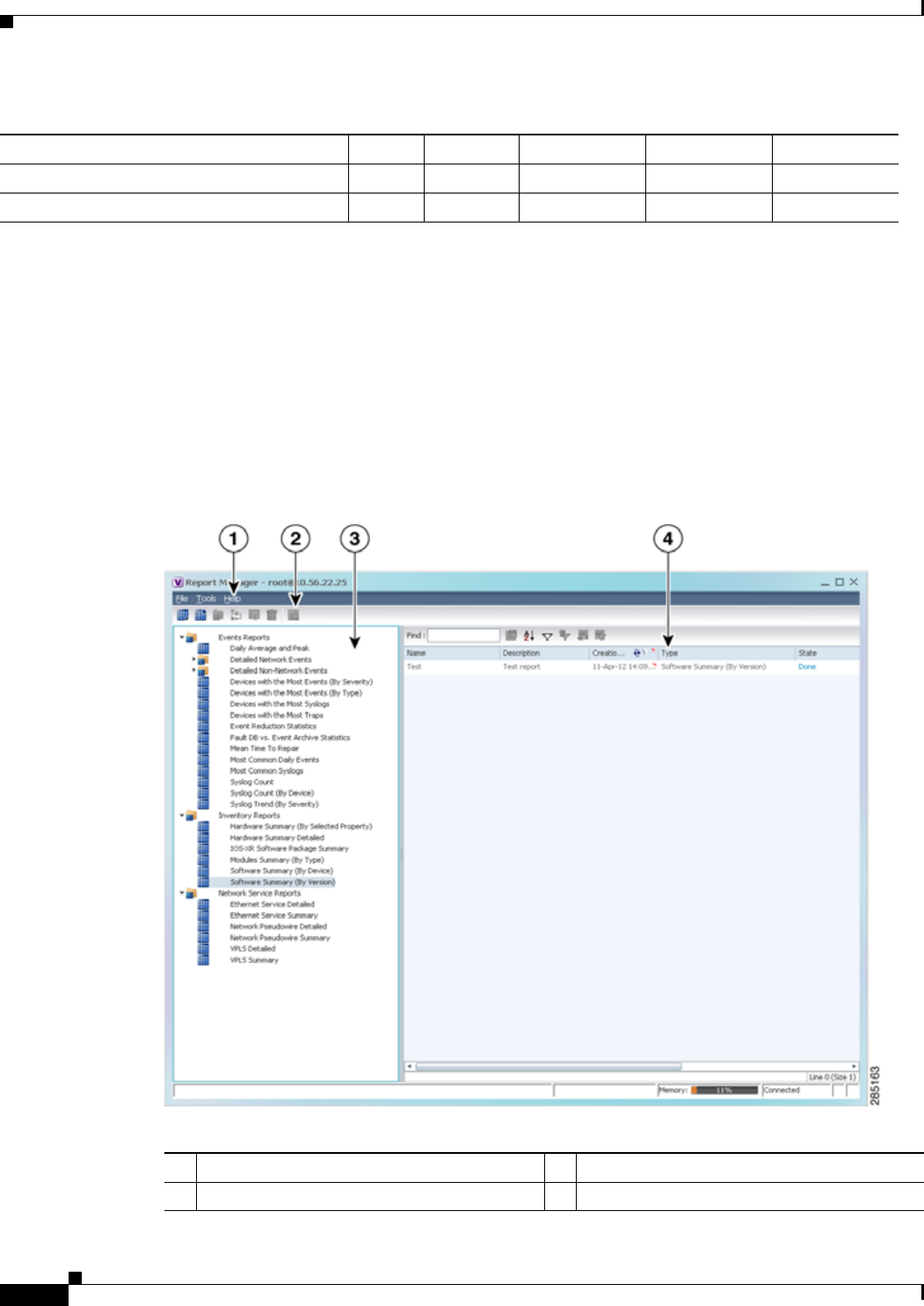
10-4
Cisco Prime Network 4.0 User Guide OL-29343-01
Chapter 10 Working with Reports
Using the Report Manager
Using the Report Manager
The Report Manager is available from Prime Network Vision, Prime Network Events, and Prime
Network Administration by choosing Reports > Report Manager. The Report Manager (shown in
Figure 10-1) enables you to run standard reports, such as the number of syslogs by device.
The Report Manager also enables you to create reports and folders, view previously generated reports,
define report types for your use, and organize reports in a manner suited to your environment and needs.
Figure 10-1 Report Manager Window
View report folder properties X X X X X
View report type properties X X X X X
1. You cannot perform this action on system-generated folders, such as the Events Reports folder.
Table 10-5 Default Permission/Security Level Required for Working with Report Folders (continued)
Task Viewer Operator OperatorPlus Configurator Administrator
1Menu bar 3Navigation tree with report types and folders
2Toolbar 4Content pane
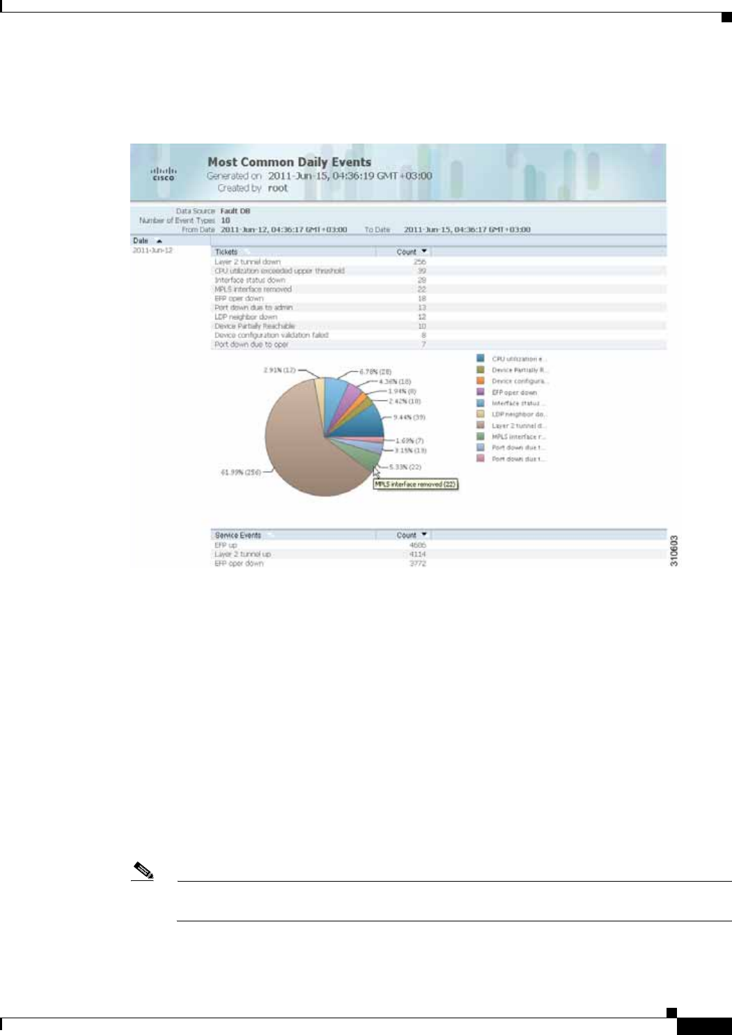
10-5
Cisco Prime Network 4.0 User Guide
OL-29343-01
Chapter 10 Working with Reports Using the Report Manager
Figure 10-2 shows an example of a generated report with a pie chart.
Figure 10-2 Sample Report
Generated reports contain the following information in the report heading:
• Report name
• Date, time, and time zone in which the report was generated
• Name of user who generated the report
Depending on the type of report, the following additional information can appear in the report heading:
• Source of the data, such as the fault or alarm database
• Time period covered by the report
• Number of items included in the report
• Any filters or maps applied to the report
A report might also include a pie chart. If you hover your mouse cursor over a section in the pie chart, a
tooltip displays the information associated with that section, such as IP address, number of events, type
of event, or percentage of total events.
Note Not all reports include pie charts. In addition, reports that normally include a pie chart do not
display a pie chart if the chart exceeds 25 slices.
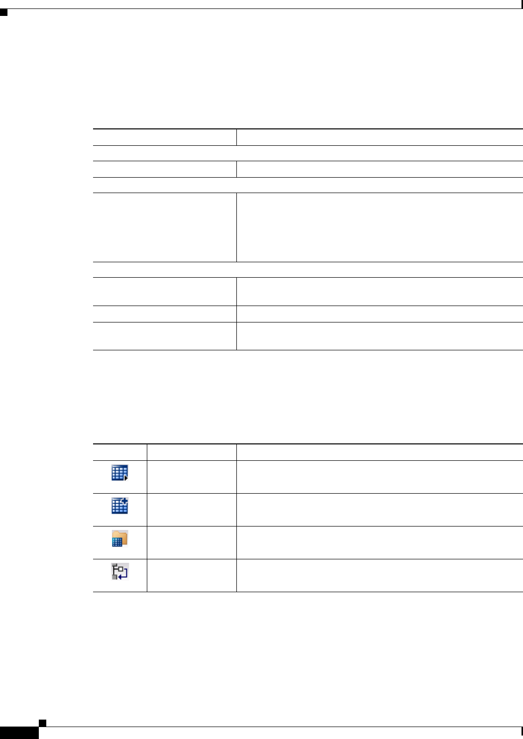
10-6
Cisco Prime Network 4.0 User Guide OL-29343-01
Chapter 10 Working with Reports
Using the Report Manager
Menu Options
Table 10-6 describes the menu options available in the Report Manager window.
Report Manager Toolbar
Table 10-7 identifies the buttons that appear in the Report Manager toolbar.
Table 10-6 Report Manager Menu Options
Option Description
File Menu
Exit Exits the Report Manager window.
Tools Menu
Change User Password Enables you to change the password used when logging into the
Prime Network client application suite. The change takes effect the
next time you log into the application.
Note The administrator can also change a user password in Prime
Network Administration.
Help Menu
Cisco Prime Network Report
Manager Help Opens the online help for Prime Network Vision and Prime Network
Events.
Cisco.com Unavailable.
About Cisco Report Manager Displays application information about Prime Network Vision and
Prime Network Events.
Table 10-7 Report Manager Toolbar Buttons
Icon Name Description
Run Generates the selected report.
Define Report of
This Type Enables you to define a report of this type that is suited specifically
to your environment.
New Folder Creates a new folder.
Move Moves one or more folders or reports that you created.

10-7
Cisco Prime Network 4.0 User Guide
OL-29343-01
Chapter 10 Working with Reports Using the Report Manager
Navigation Tree
The navigation pane displays a tree-and-branch representation of report folders and types of reports. The
highest level in the tree displays report folders. The following standard report folders are provided in
Report Manager:
• Events Reports
• Inventory Reports
• Network Service Reports
Each folder contains the types of reports that are provided with Prime Network and any user-defined
reports. For more information on the standard report types, see Table 10-12.
When you select an item in the tree, the content pane displays the generated reports as follows:
• If you select a folder, the content pane lists all reports that have been generated using any of the
report types in that folder.
• If you select a report type, the content pane lists all reports that have been generated of that report
type.
Content Pane
The content pane lists all reports generated for the folder or report type selected in the navigation tree.
You can double-click a report to view the report in HTML format.
Figure 10-3 shows an example of the content pane.
Rename Renames a folder that you created.
Delete Deletes one or more folders that you created.
Delete Report Deletes one or more selected reports.
View Displays the selected report in HTML format.
Table 10-7 Report Manager Toolbar Buttons (continued)
Icon Name Description
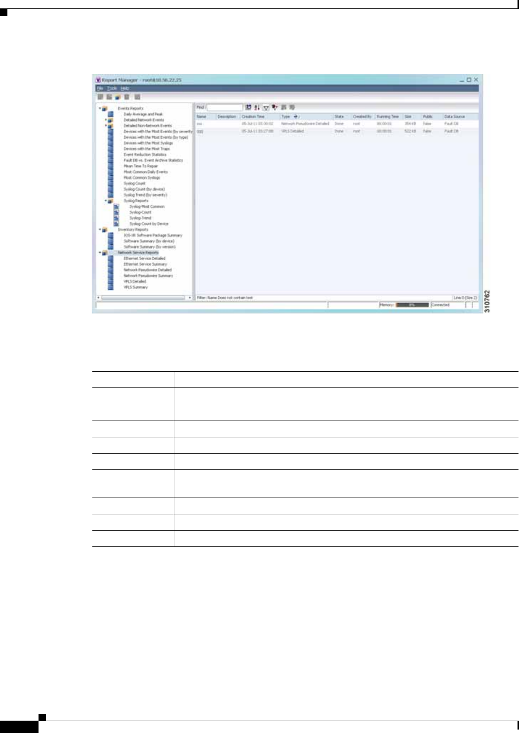
10-8
Cisco Prime Network 4.0 User Guide OL-29343-01
Chapter 10 Working with Reports
Using the Report Manager
Figure 10-3 Reports Manager Content Pane
Table 10-8 describes the information displayed in the content pane for each report.
Table 10-8 Reports Manager Content Pane Information
Attribute Description
Name Name of the report.
Double-click the report to view the report in HTML format.
Description Brief description of the report.
Creation Time Date and time when the report was generated.
Type Report type.
State State of the report: Running, Done, Canceled, or Failed. For more information
about the Failed state, see Generating Reports, page 10-22.
Created By User who created the report.
Running Time Amount of time it takes for the report to be complete.
Size Report size.

10-9
Cisco Prime Network 4.0 User Guide
OL-29343-01
Chapter 10 Working with Reports Using the Report Manager
Note Reports are purged from Prime Network after 90 days by default. This setting can be modified by
changing the setting in Prime Network Administration. For more information, see the Cisco Prime
Network 4.0 Administrator Guide.
Reports Right-Click Options
Right-click options are available for:
• Navigation Pane Folders, page 10-9
• Navigation Pane Reports, page 10-10
• Content Pane Reports, page 10-10
Navigation Pane Folders
Table 10-9 describes the options available when you right-click a folder in the navigation pane.
Public Availability of the report to other users:
• True—The report is available to all users.
• False—The report is available to only the user who generated the report and
the administrator.
Data Source Source of the report data.
• Fault Database—Contains active network events (network events, alarms, and
tickets) and non-network events (system, audit, security, provisioning, and so
forth). As active network events age, they are moved to an archive partition in
the database. Eventually network and non-network events are purged
according to their age.
• Event Archive—Contains all raw events that are sent from devices to Prime
Network. By default, saving raw events to the Event Archive is enabled.
• Network element—Information is retrieved from the NE.
For more information on the Fault Database and Event Archive, see the see the
Cisco Prime Network 4.0 Administrator Guide.
Table 10-8 Reports Manager Content Pane Information (continued)
Attribute Description
Table 10-9 Report Manager Navigation Pane Folder Right-Click Options
Option Description
New Folder Creates a new folder.
Delete Deletes a user-defined folder.
Rename Renames a user-defined folder.
Move Moves a user-defined folder.
Properties Lists the folder contents. For more information on this ndow, see Viewing
Folder and Report Type Properties, page 10-47.

10-10
Cisco Prime Network 4.0 User Guide OL-29343-01
Chapter 10 Working with Reports
Using the Report Manager
Navigation Pane Reports
Table 10-10 describes the options available when you right-click a report in the navigation pane.
Content Pane Reports
Table 10-11 describes the options available when you right-click a report in the content pane.
Table 10-10 Report Manager Navigation Pane Report Right-Click Options
Option Description
Run Displays the Run Report dialog box so you can run a report of this type
specifically for your environment and adds the generated report to the table
in the content pane.
Define Report of This
Type This option is available only for Cisco-supplied report types.
Displays the Define Report dialog box so you can create a report of this type
specifically for your environment, and adds the newly defined report to the
navigation tree.
Delete Deletes a user-defined report.
Move Moves a user-defined report.
Properties For a standard report type, displays the Reports Type Properties window
which includes a brief description of the report and enables you to generate
the report. For more information on the Reports Type Properties window, see
Viewing Report Properties, page 10-44.
For a user-defined report, displays the Edit report dialog box so that you can
modify the currently defined settings and generate the report.
Table 10-11 Report Manager Content Pane Report Right-Click Options
Option Description
View As Displays the report in the selected format:
• HTML
• PDF
• CSV
• XLS
• XML
The default option, HTML, is displayed in bold font. For more information on
viewing reports, see Viewing and Saving Reports, page 10-40.
Rename Renames the selected report.
Share or Unshare Shares the selected reports or limits them to your viewing only. The option toggles
between Share and Unshare, as appropriate for the selected reports.
By default, the Share and Unshare options are available only to users with
administrator access. These options are available to other users only if an
administrator has enabled sharing in Prime Network Administration. For more
information, see the Cisco Prime Network 4.0 Administrator Guide.
Delete Report Deletes the selected reports.

10-11
Cisco Prime Network 4.0 User Guide
OL-29343-01
Chapter 10 Working with Reports Report Categories
Report Categories
Prime Network Vision provides reports related to:
• Events—See Events Reports, page 10-11.
• Inventory—See Inventory Reports, page 10-18.
• Network services—See Network Service Reports, page 10-20.
Events Reports
Prime Network Vision provides the following standard event report types:
• General report types, as described in Table 10-12.
• Detailed network event reports, as described in Table 10-13.
• Detailed non-network event reports, as described in Table 10-14.
Cancel This option is displayed only while the selected report is being generated or
queued.
Cancels the report that is being generated or is queued.
Show Only
Selected Rows Displays only the rows that you select.
Show All Rows Displays all table rows that meet the current filtering criteria.
Properties Displays the Reports Type Properties window, which includes a brief description
of the report and enables you to edit its name and description.
Table 10-11 Report Manager Content Pane Report Right-Click Options (continued)
Option Description
Table 10-12 Standard Events Report Types
Report Name Description Data Source
Daily
Average and
Peak
For each day of the specified time period, the peak number and average rate of syslogs and
traps for each of the following time periods:
• Second
• Ten seconds
• Minute
• Hour
• Day
Fault Database

10-12
Cisco Prime Network 4.0 User Guide OL-29343-01
Chapter 10 Working with Reports
Report Categories
Database
Monitoring For regular time intervals:
• Number of active tickets
• Number of active alarms
• Number of active events
• Number of unconnected events
• Number of auto-archive candidates
• Number of notifications
• Biggest Ticket ID
• Number of event count in the biggest ticket
• Actionable Event rate per second
• Number of dangling events handled by the integrity process
• Number of tickets created by the integrity process
Fault Database
Devices with
the Most
Events (By
Severity)
For the specified number of devices with the most events, the following information for each
device for the specified time period:
• Severity of the events associated with the device, sorted by severity
• Number of events for each severity
A pie chart presents the information by device and percentage in a graphical format.
Fault Database
Devices with
the Most
Events (By
Type)
For the specified number of devices with the most events, the following information for each
device for the specified time period:
• Type of events associated with the device
• Number of events received for each event type
A pie chart presents the information by device and percentage in a graphical format.
Fault Database
Devices with
the Most
Syslogs
For the specified number of devices with the most syslogs, the number of syslog messages for
each device for the specified time period.
You can run this report on the Prime Network Fault Database or the Event Archive.
A pie chart presents the information by device and percentage in a graphical format.
User choice:
• Fault
Database
• Event
Archive
Devices with
the Most
Traps
For the specified number of devices with the most traps, the number of traps associated with
each device for the specified time period.
You can run this report on the Fault Database or the Event Archive.
A pie chart presents the information by device and percentage in a graphical format.
User choice:
• Fault
Database
• Event
Archive
Table 10-12 Standard Events Report Types (continued)
Report Name Description Data Source

10-13
Cisco Prime Network 4.0 User Guide
OL-29343-01
Chapter 10 Working with Reports Report Categories
Event
Reduction
Statistics
For the specified devices and time period:
• Names of those tickets with:
–
The root cause in the device list
–
The ticket creation time within the specified period
• For each ticket type identified:
–
Number of tickets of that type
–
Fewest number of correlated events
–
Highest number of correlated events
–
Average number of correlated events
Fault Database
Events
Troubleshoo
ting Info
Provides the following information:
• State—The event condition.
• Troubleshooting—The probable cause, action to be taken, and the clearing condition.
Fault Database
Fault DB vs.
Event
Archive
Statistics
For each day in the specified time period, the number of each of the following items in the
Fault Database and the Event Archive:
• Syslogs
• Traps
• Tickets
• Correlated events
• Uncorrelated events
• Nonnetwork events
• Network-originated events
• Network-originated and service events
Fault Database
and Event
Archive
Mean Time
to Repair For the specified devices and time period:
• Names of those tickets with:
–
The root cause in the device list
–
The ticket creation time within the specified period
• For each ticket type identified:
–
Whether the tickets were cleared by the user or network
–
Number of tickets
–
Minimum time (in seconds) to repair
–
Maximum time (in seconds) to repair
–
Average time (in seconds) to repair
Note The time to repair is based on the ticket creation time and the time the ticket was last
modified. For example, if you acknowledge a ticket after it has been cleared. the
acknowledgement time affects the time to repair for that ticket.
Fault Database
Table 10-12 Standard Events Report Types (continued)
Report Name Description Data Source

10-14
Cisco Prime Network 4.0 User Guide OL-29343-01
Chapter 10 Working with Reports
Report Categories
Most
Common
Daily Events
For each day in the specified time period:
• Specified number of most common tickets, service events, syslogs, and traps
• Number of each type of ticket, service event, syslog, and trap
• If selected, a pie chart presenting the events by percentage in a graphical format
Fault Database
Most
Common
Syslogs
Most common syslog messages and the number of each for the specified time period and
devices.
A pie chart presents the information by syslog message and percentage in a graphical format.
Fault Database
Syslog
Count Number of syslog messages by type for the specified time period with the times of the first
and last occurrences.
A pie chart presents the information by syslog message and percentage in a graphical format.
Fault Database
Syslog
Count (By
Device)
For each device, the type and number of each syslog message and the times of the first and
last occurrences for each type.
A pie chart presents the information by device and percentage in a graphical format.
Fault Database
Syslog
Trend (By
Severity)
For the specified devices, the trend of specified syslog messages in graph format:
• By priority
• For the specified time period
• At the specified intervals
Fault Database
Table 10-12 Standard Events Report Types (continued)
Report Name Description Data Source

10-15
Cisco Prime Network 4.0 User Guide
OL-29343-01
Chapter 10 Working with Reports Report Categories
Table 10-13 Detailed Network Events Report Types
Report Name Description Data Source
Detailed Event
Count (By Device) For each device, the following information for the specified time period:
• For syslogs:
–
Syslog severities
–
Number of syslogs per severity
–
Syslog type
–
Number of each syslog type
• For traps:
–
Trap severities
–
Number of traps per severity
–
Trap type
–
Number of each trap type
• For tickets:
–
Ticket severities
–
Number of tickets per severity
–
Ticket type
–
Number of each ticket type
–
You can select a maximum of 1000 devices for this report.
Fault Database
Detailed Service
Events For each service event of the specified severities, time period, and devices:
• Event severity
• Event identifier
• Timestamp
• Brief and detailed descriptions
• Device on which the event occurred
• Alarm identifier
• Ticket identifier
• Causing event identifier
• Duplication count
• Reduction count
Fault Database
Detailed Syslogs For each device that is selected, the following information from the Event Archive for
the specified time period:
• IP address
• Date and time of each syslog, in ascending order
• Syslog raw data or description, depending on the data source
The maximum number of syslogs retrieved for this report is 250,000.
User selection:
Event Archive
or Fault
Database

10-16
Cisco Prime Network 4.0 User Guide OL-29343-01
Chapter 10 Working with Reports
Report Categories
Detailed Tickets For each ticket of the specified severities, time period, and device:
• Ticket severity
• Ticket identifier
• Last modification time
• Root event time
• Description
• Entity that caused the alarm
• Whether or not the ticket is acknowledged
• Ticket creation time
• Event count
• Affected devices count
• Duplication count
• Reduction count
• Alarm count
Fault Database
Detailed Traps For each managed device that is selected, the following information for the specified
time period:
• IP address
• Time of trap
• SNMP version
• Trap description
• Generic or device-specific trap OID, if the source is the Event Archive
• Long description, if the data source is the Fault Database
The maximum number of traps retrieved for this report depends on whether the Long
Description check box is selected. When checked, a maximum of 30,000 traps are
retrieved. When this check box is not checked, a maximum of 100,000 traps are
retrieved for this report.
User Selection:
Event Archive
or Fault
Database
Table 10-13 Detailed Network Events Report Types (continued)
Report Name Description Data Source

10-17
Cisco Prime Network 4.0 User Guide
OL-29343-01
Chapter 10 Working with Reports Report Categories
Table 10-14 Detailed Non-Network Events Report Types
Report Name Description Data Source
Detailed Audit
Events For each audit event included in the report for the specified time period, severities,
and search criteria:
• Event severity
• Event identifier
• Timestamp
• Description
• Command name
• Command signature
• Command parameters
• Originating IP address
• Username
Fault Database
Detailed
Provisioning Events For each provisioning event included in the report for the specified time period,
severities, and search criteria:
• Event severity
• Event identifier
• Timestamp
• Description
• Location
• Username
• Device username
• Status
Fault Database
Detailed Security
Events For each security event included in the report for the specified time period,
severities, and search criteria:
• Event severity
• Event identifier
• Timestamp
• Description
• Location
• Username
• Originating IP address
Fault Database

10-18
Cisco Prime Network 4.0 User Guide OL-29343-01
Chapter 10 Working with Reports
Report Categories
Inventory Reports
Table 10-15 describes the standard inventory report types provided by Prime Network Vision and the
data source.
Detailed System
Events For each system event included in the report for the specified time period, severities,
and search criteria:
• Event severity
• Event identifier
• Timestamp
• Description
• Location
Fault Database
Table 10-14 Detailed Non-Network Events Report Types (continued)
Report Name Description Data Source
Table 10-15 Standard Inventory Report Types
Report Name Description Data Source
Hardware
Detailed For each device included in the report:
• IP address
• Device series
• Element type
You can view other hardware information for each device by selecting the required
items from the available list as given below:
• Chassis—chassis description, chassis serial number, shelf description, shelf serial
number, and shelf status
• Module—module name, sub module name, module status, hardware type, and
hardware version
• Port—port location, port type, porting sending alarm, port alias, port status, port
managed, PID, and pluggable type serial number.
Network
elements
Hardware
Summary For each device included in the report:
• IP address
• System name
• Serial number
• Element type
• Device series
• Vendor
• Product
• Chassis
You can group the report contents by vendor, product, device series, element type,
system name, or chassis and specify part or whole of the selected entity, if required.
Network
elements

10-19
Cisco Prime Network 4.0 User Guide
OL-29343-01
Chapter 10 Working with Reports Report Categories
IOS-XR Software
Package
Summary
For each device included in the report:
• Device name
• Element type
• IP address
• Serial number
• Cisco IOS XR software version
• For each software package installed on the device:
–
Storage location
–
Software package name
–
Module name
–
Software package state: Active or Inactive
Network
elements
Modules
Summary (By
Type)
For each device filtered by module type:
• IP address
• Module serial number
• Module hardware version
• Module software version
You can filter the report contents by specifying part or whole of the module type.
Network
elements
Software
Summary (By
Device)
For each device included in the report:
• Device name
• Element type
• IP address
• Serial number
• Software version on the device
• Name of image file
Network
elements
Software
Summary (By
Version)
For each software version included in the report:
• Number of devices running the version
• Device names
• Element types
• Device IP address
• Device serial number
• Name of image file
Network
elements
Table 10-15 Standard Inventory Report Types (continued)
Report Name Description Data Source

10-20
Cisco Prime Network 4.0 User Guide OL-29343-01
Chapter 10 Working with Reports
Report Categories
Network Service Reports
Table 10-16 describes the standard network service report types provided by Prime Network Vision and
the data source.
Table 10-16 Standard Network Service Report Types
Report Name Description Data Source
Ethernet Service
Detailed For each Ethernet service in the report:
• Ethernet service or Layer 2 VPN name
• Business tag assigned to the Ethernet service or Layer 2 VPN instance
• EVC name
• Business tag assigned to the EVC
• Maps containing the Ethernet service or Layer 2 VPN
• Edge EFPs associated with the EVC or Layer 2 VPN
• EFD fragment names
• EFD fragment type
You can filter report content by specifying part or all of the:
• Ethernet service name
• EVC name
• Ethernet service business tag
• EVC business tag
• Map name
Fault
Database
Ethernet Service
Summary For each Ethernet service in the report:
• Ethernet service or Layer 2 VPN name
• Business tag assigned to the Ethernet service or Layer 2 VPN instance
• EVC name
• Business tag assigned to the EVC
• Maps containing the Ethernet service or Layer 2 VPN
You can filter report content by specifying part or all of the:
• Ethernet service name
• EVC name
• Ethernet service business tag
• EVC business tag
• Map name
Fault
Database

10-21
Cisco Prime Network 4.0 User Guide
OL-29343-01
Chapter 10 Working with Reports Report Categories
Network
Pseudowire
Detailed
For each network pseudowire in the report:
• Pseudowire name
• Pseudowire type
• Business tag assigned to the pseudowire
• Maps containing the pseudowire
• Pseudowire details
• Type of pseudowire, such as pseudowire edge, Ethernet flow point, or switching
entity
You can filter report content by specifying part or all of the:
• Pseudowire name
• Pseudowire type
• Business tag
• Map name
Fault
Database
Network
Pseudowire
Summary
For each network pseudowire in the report:
• Pseudowire name
• Pseudowire type
• Business tag assigned to the pseudowire
• Maps containing the pseudowire
You can filter the report content by specifying part or all of the:
• Pseudowire name
• Pseudowire type
• Business tag
• Map name
Fault
Database
VPLS Detailed For each VPLS or H-VPLS instance in the report:
• VPLS or H-VPLS name
• Business tag associated with the VPLS or H-VPLS instance
• Maps containing the VPLS or H-VPLS instance
• VPLS details
• Type of VPLS service, such as VPLS forward, access EFP, or core pseudowire
You can filter report content by specifying part or all of the:
• VPLS or H-VPLS name
• Business tag
• Map name
Fault
Database
Table 10-16 Standard Network Service Report Types (continued)
Report Name Description Data Source

10-22
Cisco Prime Network 4.0 User Guide OL-29343-01
Chapter 10 Working with Reports
Generating Reports
Generating Reports
You can generate reports in any of the following ways:
• Generating Reports from Report Manager, page 10-23
• Generating Reports from the Reports Menu, page 10-37
• Generating Reports from Prime Network Vision, page 10-38
You can generate reports only for devices that are within your scope.
Note Report Manager generates reports up to 150 MB in size. If you generate a report that exceeds this limit:
• Report Manager window displays Failed in the State column.
• An error message is entered in the log stating that the report failed because the resulting output is
too large.
To run the report successfully, enter more specific report criteria or limit the time period covered by the
report.
Database Load and Report Generation
If you generate reports while Prime Network Vision is working under a database load, the reports move
to a Load mode which is indicated by a system event. While Prime Network Vision is in Load mode, the
reports currently running are cancelled and new reports are queued.
After Prime Network Vision returns to normal operation and is no longer operating under a load, a new
system event is generated and the queued reports start running.
Report Generation Failure
If a report fails to generate successfully, the State column contains the word Failed. Click Failed to view
the reason for the failure. A window is displayed with the cause of the failure, such as The disk space
allocated for report storage is full or AVM 84 was restarted while the report was running.
VPLS Summary For each VPLS or H-VPLS instance in the report:
• VPLS or H-VPLS name
• Business tag assigned to the VPLS or H-VPLS instance
• Maps containing the VPLS or H-VPLS instance
You can filter report content by specifying part or all of the:
• VPLS or H-VPLS name
• Business tag
• Map name
Fault
Database
Table 10-16 Standard Network Service Report Types (continued)
Report Name Description Data Source

10-23
Cisco Prime Network 4.0 User Guide
OL-29343-01
Chapter 10 Working with Reports Generating Reports
Report Generation Canceled
If a report is canceled before it completes, the State column contains the word Canceled. Click Canceled
to view the reason for the cancellation. A window is displayed with the cause of the cancellation, such
as The report was canceled by user <user-name> or The report was canceled by the system to prevent
system overload.
Generating Reports from Report Manager
Prime Network Vision provides three report categories as described in Report Categories, page 10-11.
The information that you need to provide when generating a report depends on the report type. The
following topics describe the information required to generate each report type:
• Generating Events Reports, page 10-23
• Generating Inventory Reports, page 10-31
• Generating Network Service Reports, page 10-34
Note You can generate reports only for devices that are within your scope.
Generating Events Reports
To generate an events report using Report Manager:
Step 1 In Prime Network Vision, Prime Network Events, or Prime Network Administration, choose
Reports > Report Manager.
Step 2 In the Report Manager window, choose Events Reports > report-type.
For information on the reports available for events, see Table 10-12.
Step 3 Generate the report by right-clicking the report type, then choosing Run.
The Run Report dialog box is displayed. An example is shown in Figure 10-4. The fields displayed in
the Run Report dialog box vary depending on the type of report.

10-24
Cisco Prime Network 4.0 User Guide OL-29343-01
Chapter 10 Working with Reports
Generating Reports
Figure 10-4 Events Report - Run Report Dialog Box
Step 4 In the Run Report dialog box, specify the report settings as follows:
• For standard events reports, use the information in Table 10-17.
• For detailed network reports, use the information in Table 10-18.
• For detailed non-network reports, use the information in Table 10-19.

10-25
Cisco Prime Network 4.0 User Guide
OL-29343-01
Chapter 10 Working with Reports Generating Reports
Table 10-17 Events Report - Run Report Dialog Box Fields
Option Description
Report Settings
Report Name Enter a unique name for the report, from 1 to 150 characters in length.
Report names cannot include the following characters: ;?<>/:\"#*|.
Description Enter a brief description of the report.
Report Security This field is displayed only if report sharing is enabled in Prime Network
Administration.
Indicate the level of security for the report by clicking the appropriate
option:
• Private—The report can be viewed and used only by the report creator
and the administrator.
• Public—The report can be viewed and used by all other users, regardless
of whether the devices are listed in the report are in the user’s scope.
Note You can share reports with others only if sharing is enabled in Prime
Network Administration. For more information, see the Cisco Prime
Network 4.0 Administrator Guide.
Display n This field does not appear for all reports.
Enter the number of items to be displayed in the generated report.
Data Source This field does not appear for all reports.
Select the source of information to use for the report: Fault Database or
Event Archive.
Include pie charts in
report output This field does not appear for all reports.
Check the check box to view pie charts in the report with the standard
numerical output.
Date Selection
Last Specify the length of time before the current date and time, and the unit of
measure: seconds, minutes, hours, days, weeks, or months.
From Date
To Date
Specify the date range for the report:
1. Click From Date.
2. In the From date field, enter the start date for the time period, or click
the drop-down arrow to select the start date from a calendar.
3. Enter a time for the start date, using the format HH MM SS.
4. In the To Date field, enter the end date for the time period, or click the
drop-down arrow to select the end date from a calendar.
5. Enter a time for the end date, using the format HH MM SS.

10-26
Cisco Prime Network 4.0 User Guide OL-29343-01
Chapter 10 Working with Reports
Generating Reports
Device Selection
Select Devices Note
• You can add only those devices that are within your scope.
• A user with the Administrator role can select unmanaged devices (by IP
address) for reports that run on the Event Archive.
Select devices to include in the report:
1. Click Select Devices.
2. Click Add.
3. In the Add Network Element dialog box, select devices using either of
the following methods:
–
To select devices that meet specific criteria, click Search and enter
the required criteria.
–
To select from all network elements, click Show All.
4. In the list of displayed elements, select the network elements that you
want to include in the report. You can select multiple network elements
at a time.
5. Click OK.
All Devices This field does not appear for all reports.
Click All Devices to include all devices in your scope in the report.
Syslog Trend (by Severity) Report—Additional Report Specifications
Intervals In the Grouped by drop-down list, choose the unit of time to use for tracking
the trend: Seconds, Minutes, Hours, or Days.
Severity Check the check boxes of the syslog message severities to be included in the
report: All, Critical, Major, Minor, Warning, Cleared, Information, and
Indeterminate.
Syslog Messages Specify the syslog messages to be included in the report:
• To include selected syslog messages in the report, in the list of syslog
messages on the left, select the required syslog messages, and then click
Add Selected to move them to the list of syslog messages on the right.
• To include all syslog messages in the report, click Add All.
To find syslog messages that match a string, enter the string in the Find field.
The list of syslog messages is automatically updated to include only those
messages that contain the string you enter.
Click the Sort Order button to sort the syslog messages in alphabetic or
reverse alphabetic order.
Table 10-17 Events Report - Run Report Dialog Box Fields (continued)
Option Description

10-27
Cisco Prime Network 4.0 User Guide
OL-29343-01
Chapter 10 Working with Reports Generating Reports
Table 10-18 Detailed Network Events Reports - Run Report Dialog Box Fields
Option Description
Report Settings
Report Name Enter a unique name for the report, from 1 to 150 characters in length.
Report names cannot include the following characters: ;?<>/:\"#*|.
Description Enter a brief description of the report.
Report Security This field is displayed only if report sharing is enabled in Prime Network
Administration.
Indicate the level of security for the report by clicking the appropriate
option:
• Private—The report can be viewed and used only by the report creator
and the administrator.
• Public—The report can be viewed and used by all other users, regardless
of whether the devices are listed in the report are in the user’s scope.
Note You can share reports with others only if sharing is enabled in Prime
Network Administration. For more information, see the Cisco Prime
Network 4.0 Administrator Guide.
Data Source This field does not appear for all reports.
Select the source of information to use for the report: Fault Database or
Event Archive.
Date Selection
Last Specify the length of time before the current date and time, and the unit of
measure: seconds, minutes, hours, days, weeks, or months.
From Date
To Date
Specify the date range for the report:
1. Click From Date.
2. In the From date field, enter the start date for the time period, or click
the drop-down arrow to select the start date from a calendar.
3. Enter a time for the start date, using the format HH MM SS.
4. In the To Date field, enter the end date for the time period, or click the
drop-down arrow to select the end date from a calendar.
5. Enter a time for the end date, using the format HH MM SS.

10-28
Cisco Prime Network 4.0 User Guide OL-29343-01
Chapter 10 Working with Reports
Generating Reports
Device Selection
Select Devices Note
• You can add only those devices that are within your scope.
• A user with the Administrator role can select unmanaged devices (by IP
address) for reports that run on the Event Archive.
• The Detailed Event Count (by device) report accepts a maximum of
1000 devices.
Select devices to include in the report:
1. Click Select Devices.
2. Click Add.
3. In the Add Network Element dialog box, select devices using either of
the following methods:
–
To select devices that meet specific criteria, click Search and enter
the required criteria.
–
To select from all network elements, click Show All.
4. In the list of displayed elements, select the network elements that you
want to include in the report. You can select multiple network elements
at a time.
5. Click OK.
All Devices This field does not appear for all reports.
Click All Devices to include all devices in your scope in the report.
Severity
Severity This field does not appear for all reports.
Check the check boxes of the syslog message severities to be included in the
report: All, Critical, Major, Minor, Warning, Cleared, Information, and
Indeterminate.
Detailed Service Events Report—Additional Report Specifications
Description Contains Enter the string that the service event must contain to be included in the
report.
Detailed Syslogs Report—Additional Report Specifications
Syslogs Description This field is displayed if you choose Fault DB for the data source.
In the Description Contains field, enter the string that the syslog must
contain to be included in the report.
Syslogs Raw Data This field is displayed if you choose Event Archive for the data source.
In the Raw Data Contains field, enter the string that the syslog raw data must
contain to be included in the report.
Table 10-18 Detailed Network Events Reports - Run Report Dialog Box Fields (continued)
Option Description

10-29
Cisco Prime Network 4.0 User Guide
OL-29343-01
Chapter 10 Working with Reports Generating Reports
Detailed Traps Report—Additional Report Specifications
Traps Detailed
Description In the Description Contains field, enter the string that the trap must contain
to be included in the report.
Long Description This option is enabled if you choose Fault DB for the data source.
1. Check the Show Long Description check box to include the long
description in the report.
2. In the Long Description Contains field, enter the string that the long
description must contain to be included in the report.
SNMP Version Specify the SNMP versions to include in the report: All, 1, 2, or 3.
Generic This option is enabled if you choose Event Archive for the data source.
Specify the generic traps to include in the report:
1. Select the generic traps to include in the report:
–
All—Include all generic traps
–
0—coldStart
–
1—warmStart
–
2—linkDown
–
3—linkUp
–
4—authenticationFailure
–
5—egpNeighborLoss
–
6—enterpriseSpecific
2. If you select generic type 6, enter the OIDs (comma separated) in the
Vendor Specific field.
The Vendor Specific field accepts a maximum of 125 digits.
Table 10-18 Detailed Network Events Reports - Run Report Dialog Box Fields (continued)
Option Description

10-30
Cisco Prime Network 4.0 User Guide OL-29343-01
Chapter 10 Working with Reports
Generating Reports
Table 10-19 Detailed Non-Network Events Reports - Run Report Dialog Box Fields
Option Description
Report Settings
Report Name Enter a unique name for the report, from 1 to 150 characters in length.
Report names cannot include the following characters: ;?<>/:\"#*|.
Description Enter a brief description of the report.
Report Security This field is displayed only if report sharing is enabled in Prime Network
Administration.
Indicate the level of security for the report by clicking the appropriate
option:
• Private—The report can be viewed and used only by the report creator
and the administrator.
• Public—The report can be viewed and used by all other users, regardless
of whether the devices are listed in the report are in the user’s scope.
Note You can share reports with others only if sharing is enabled in Prime
Network Administration. For more information, see the Cisco Prime
Network 4.0 Administrator Guide.
Date Selection
Last Specify the length of time before the current date and time, and the unit of
measure: seconds, minutes, hours, days, weeks, or months.
From Date
To Date
Specify the date range for the report:
1. Click From Date.
2. In the From date field, enter the start date for the time period, or click
the drop-down arrow to select the start date from a calendar.
3. Enter a time for the start date, using the format HH MM SS.
4. In the To Date field, enter the end date for the time period, or click the
drop-down arrow to select the end date from a calendar.
5. Enter a time for the end date, using the format HH MM SS.
Severity
Severity Check the check boxes of the syslog message severities to be included in the
report: All, Critical, Major, Minor, Warning, Cleared, Information, and
Indeterminate.
Detailed Audit Events Report—Additional Report Specifications
Description Contains Enter the string that the event must contain to be included in the report.
Command Name
Contains Enter the string that the command name must contain to be included in the
report.
Originator IP Contains Enter the string that the originating IP address must contain to be included
in the report.
User Name Contains Enter the string that the username must contain to be included in the report.

10-31
Cisco Prime Network 4.0 User Guide
OL-29343-01
Chapter 10 Working with Reports Generating Reports
Step 5 To schedule a report to run immediately or at a later point in time, click the Scheduling tab. For more
information, see Scheduling Reports, page 10-38.
Step 6 Click OK.
The report appears in the table in the content pane with a state of Running, if the report is scheduled to
run immediately, or Scheduled, if the report is scheduled to run at a later point in time. When the report
is complete, the state changes to Done.
You can view the reports when the state is Done. Occasionally, some report formats require additional
time for generation. If so, a progress bar is displayed, indicating that the report is being created and will
be available soon.
If the report exceeds 150 MB, the state changes to Failed and an error message is written to the log. We
recommend running the report with more specific criteria or a shorter time period to avoid this situation.
If no data is found for the report, the report states that no results were found.
Generating Inventory Reports
To generate an inventory report using Report Manager:
Step 1 In Prime Network Vision, Prime Network Events, or Prime Network Administration, choose
Reports > Report Manager.
Step 2 In the Report Manager window, choose Inventory Reports > report-type.
For information on the standard reports available for inventory, see Table 10-15.
Step 3 Right-click the report type, then choose Run.
The Run Report dialog box is displayed as shown in Figure 10-5.
Detailed Provisioning Events Report—Additional Report Specifications
Description Contains Enter the string that the trap must contain to be included in the report.
User Name Contains Enter the string that the username must contain to be included in the report.
Status Choose the statuses to be included in the report: All, Unknown, Configuring,
Success, and Fail.
Detailed Security Events Report—Additional Report Specifications
Description Contains Enter the string that the event must contain to be included in the report.
Originator IP Contains Enter the string that the originating IP address must contain to be included
in the report.
User Name Contains Enter the string that the username must contain to be included in the report.
Detailed System Events Report—Additional Report Specifications
Description Contains Enter the string that the event must contain to be included in the report.
Table 10-19 Detailed Non-Network Events Reports - Run Report Dialog Box Fields (continued)
Option Description

10-32
Cisco Prime Network 4.0 User Guide OL-29343-01
Chapter 10 Working with Reports
Generating Reports
Figure 10-5 Inventory Report - Run Report Dialog Box
Step 4 Enter the required information in the Run Report dialog box as described in Table 10-20.
Table 10-20 Inventory Report - Run Report Dialog Box Fields
Field Description
Report Settings
Report Name Enter a unique name for the report, from 1 to 150 characters in length.
Report names cannot include the following characters: ;?<>/:\"#*|.
Description Enter a brief description of the report.

10-33
Cisco Prime Network 4.0 User Guide
OL-29343-01
Chapter 10 Working with Reports Generating Reports
Step 5 To schedule a report to run immediately or at a later point in time, click the Scheduling tab. For more
information, see Scheduling Reports, page 10-38.
Step 6 Click OK.
The report appears in the table in the content pane with a state of Running, if the report is scheduled to
run immediately, or Scheduled, if the report is scheduled to run at a later point in time. When the report
is complete, the state changes to Done.
You can view the reports when the state is Done. Occasionally, some report formats require additional
time for generation. If so, a progress bar is displayed, indicating that the report is being created and will
be available soon.
If the report exceeds 150 MB, the state changes to Failed and an error message is written to the log. We
recommend running the report with more specific criteria or a shorter time period to avoid this situation.
If no data is found for the report, the report states that no results were found.
Report Security This field is displayed only if report sharing is enabled in Prime Network
Administration.
Indicate the level of security for the report by clicking the appropriate
option:
• Private—The report can be viewed and used only by the report creator
and the administrator.
• Public—The report can be viewed and used by all other users, regardless
of whether the devices are listed in the report are in the user’s scope.
Note You can share reports with others only if sharing is enabled in Prime
Network Administration. For more information, see the Cisco Prime
Network 4.0 Administrator Guide.
Device Selection
Select Devices Note You can add only those devices that are within your scope.
Select devices to include in the report:
1. Click Select Devices.
2. Click Add.
3. In the Add Network Element dialog box, select devices using either of
the following methods:
–
To select devices that meet specific criteria, click Search and enter
the required criteria.
–
To select from all network elements, click Show All.
4. In the list of displayed elements, select the network elements that you
want to include in the report. You can select multiple network elements
at a time.
5. Click OK.
All devices Click All Devices to include all devices in your scope in the report.
Table 10-20 Inventory Report - Run Report Dialog Box Fields (continued)
Field Description
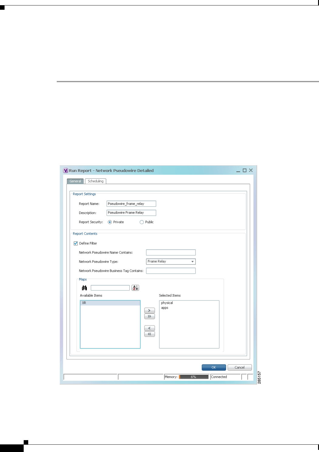
10-34
Cisco Prime Network 4.0 User Guide OL-29343-01
Chapter 10 Working with Reports
Generating Reports
Generating Network Service Reports
If you generate a detailed network service report on a large-scale setup, a message is displayed in the
Run Report dialog box recommending that you apply a filter to limit the size of the report.
To generate a network service report using Report Manager:
Step 1 In Prime Network Vision, Prime Network Events, or Prime Network Administration, choose
Reports > Report Manager.
Step 2 In the Report Manager window, choose Network Service Reports > report-type.
For information on the standard reports available for network services, see Table 10-16.
Step 3 Right-click the report type, then choose Run.
The Run Report dialog box is displayed as shown in Figure 10-6.
Figure 10-6 Network Service Report - Run Report Dialog Box

10-35
Cisco Prime Network 4.0 User Guide
OL-29343-01
Chapter 10 Working with Reports Generating Reports
Step 4 Enter the required information the Run Report dialog box as described in Table 10-21.
Table 10-21 Network Service Report - Run Report Dialog Box Fields
Field Description
Report Settings
Report Name Enter a unique name for the report, from 1 to 150 characters in length.
Report names cannot include the following characters: ;?<>/:\"#*|.
Description Enter a brief description of the report.
Report Security This field is displayed only if report sharing is enabled in Prime Network
Administration.
Indicate the level of security for the report by clicking the appropriate
option:
• Private—The report can be viewed and used only by the report
creator and the administrator.
• Public—The report can be viewed and used by all other users,
regardless of whether the devices are listed in the report are in the
user’s scope.
Note You can share reports with others only if sharing is enabled in
Prime Network Administration. For more information, see the
Cisco Prime Network 4.0 Administrator Guide.
Ethernet Service Reports—Report Contents
Define Filter Check the Define Filter check box to enter criteria that must be matched
for inclusion in the report.
You can specify match criteria in any or all of the following fields.
Ethernet Service Name
Contains Enter a string that must appear in the Ethernet service name for the
Ethernet service to be included in the report.
EVC Name Contains Enter a string that must appear in the EVC name for the EVC to be
included in the report.
Ethernet Service Business
Tag Contains Enter a string that must appear in the Ethernet service business tag for
the Ethernet service to be included in the report.
EVC Business Tag Contains Enter a string that must appear in the EVC business tag for the EVC to
be included in the report.
Maps Specify the maps to include in the report:
• To include specific maps in the report, in the list of maps on the left,
select the required maps, and then click Add Selected to move them
to the list of maps on the right.
• To include all maps in the report, click Add All.
To find maps that match a string, enter the string in the Find field. The
list of maps is automatically updated to include only those maps that
contain the string you enter.
Click the Sort Order button to sort the maps alphabetically or in reverse
alphabetic order.

10-36
Cisco Prime Network 4.0 User Guide OL-29343-01
Chapter 10 Working with Reports
Generating Reports
Step 5 To schedule a report to run immediately or at a later point in time, click the Scheduling tab. For more
information, see Scheduling Reports, page 10-38.
Network Pseudowire Reports—Report Contents
Define Filter Check the Define Filter check box to enter criteria that must be matched
for inclusion in the report.
You can specify match criteria in any or all of the following fields.
Network Pseudowire Name
Contains Enter a string that must appear in the network pseudowire name for the
pseudowire to be included in the report.
Network Pseudowire Type In the drop-down list, choose the type of network pseudowire to be
included in the report.
Network Pseudowire
Business Tag Contains Enter a string that must appear in the network pseudowire business tag
for the pseudowire to be included in the report.
Maps Specify the maps to include in the report:
• To include specific maps in the report, in the list of maps on the left,
select the required maps, and then click Add Selected to move them
to the list of maps on the right.
• To include all maps in the report, click Add All.
To find maps that match a string, enter the string in the Find field. The
list of maps is automatically updated to include only those maps that
contain the string you enter.
Click the Sort Order button to sort the maps alphabetically or in reverse
alphabetic order.
VPLS Reports—Report Contents
Define Filter Check the Define Filter check box to enter criteria that must be matched
for inclusion in the report.
You can specify match criteria in any or all of the following fields.
VPLS Name Contains Enter a string that must appear in the VPLS name for the VPLS or
H-VPLS to be included in the report.
VPLS Business Tag
Contains Enter a string that must appear in the VPLS business tag for the VPLS
or H-VPLS to be included in the report.
Maps Specify the maps to be included in the report:
• To include specific maps in the report, in the list of maps on the left,
select the required maps, and then click Add Selected to move them
to the list of maps on the right.
• To include all maps in the report, click Add All.
To find maps that match a string, enter the string in the Find field. The
list of maps is automatically updated to include only those maps that
contain the string you enter.
Click the Sort Order button to sort the maps alphabetically or in reverse
alphabetic order.
Table 10-21 Network Service Report - Run Report Dialog Box Fields (continued)
Field Description

10-37
Cisco Prime Network 4.0 User Guide
OL-29343-01
Chapter 10 Working with Reports Generating Reports
Step 6 Click OK.
The report appears in the table in the content pane with a state of Running, if the report is scheduled to
run immediately, or Scheduled, if the report is scheduled to run at a later point in time. When the report
is complete, the state changes to Done.
You can view the reports when the state is Done. Occasionally, some report formats require additional
time for generation. If so, a progress bar is displayed, indicating that the report is being created and will
be available soon.
If the report exceeds 150 MB, the state changes to Failed and an error message is written to the log. We
recommend running the report with more specific criteria or a shorter time period to avoid this situation.
If no data is found for the report, the report states that no results were found.
Generating Reports from the Reports Menu
To generate reports quickly and without opening the Reports Manager window, choose
Reports > Run Report > folder > report-type. The menus include all standard folders and reports, and
any folders or reports that you have created. After entering the required information, you can view the
report as soon as it is generated or at a later time.
Note You can generate reports only for devices that are within your scope.
To generate a report from the Reports menu:
Step 1 Choose Reports > Run Report > folder > report-type where:
• folder is the required folder.
• report-type is the required type of report.
Step 2 In the Run Report dialog box, enter the required information. For more information on the options in the
Run Report dialog box, see Generating Reports, page 10-22.
Step 3 To schedule a report to run immediately or at a later point in time, click the Scheduling tab. For more
information, see Scheduling Reports, page 10-38.
Step 4 Click OK.
Step 5 In the Running Report dialog box, select the required viewing options:
a. Check the Open Report Manager to monitor status check box to open the Report Manager
window so that you can view the report generation process. Uncheck the check box to proceed
without opening the Report Manager window.
b. Check the View report immediately upon completion check box to view the report as soon as it is
generated. If you enable this option, the report is displayed in HTML format as soon as it is
complete. Uncheck the check box to view the report at a later time by using Report Manager.
Step 6 Click OK.
Depending on your selections in Step 5, the Report Manager window is displayed, the report is
displayed, or the report is available for viewing at a later time.

10-38
Cisco Prime Network 4.0 User Guide OL-29343-01
Chapter 10 Working with Reports
Scheduling Reports
Generating Reports from Prime Network Vision
Prime Network Vision enables you to run reports on selected devices from the map and list views.
Note You can generate reports only for devices that are within your scope.
To generate a report from Prime Network Vision:
Step 1 In Prime Network Vision, select the required devices in the map or list view.
Step 2 In the navigation tree or content pane, right-click the selected devices, then choose Run
Report > folder > report-type.
Step 3 In the Run Report dialog box, enter the required information as described in Generating Reports,
page 10-22.
The devices that you select in the navigation pane or content pane are automatically included in the
report.
Step 4 To schedule a report to run immediately or at a later point in time, click the Scheduling tab. For more
information, see Scheduling Reports, page 10-38.
Step 5 Click OK.
Step 6 In the Running Report dialog box, specify the desired viewing options:
a. Check the Open Report Manager to monitor status check box to open the Report Manager
window so that you can view the report generation process. Uncheck the check box to proceed
without opening the Report Manager window.
b. Check the View report immediately upon completion check box to view the report as soon as it is
generated. If you enable this option, the report is displayed in HTML format as soon as it is
complete. Uncheck the check box to view the report at a later time by using Report Manager.
Depending on your selections in Step 6, the Report Manager window is displayed, the report is
displayed, or the report is available for viewing at a later time.
Scheduling Reports
Prime Network allows you to schedule a report to run immediately or at a later point in time.
To schedule a report:
Step 1 In Prime Network Vision, Prime Network Events, or Prime Network Administration, choose
Reports > Report Manager.
Step 2 In the Report Manager window, choose report-category > report-type.
For information on the various report categories and report types, see Report Categories, page 10-11.
Step 3 Right-click the report type, then choose Run.
The Run Report dialog box is displayed.
Step 4 In the Settings tab, specify the required report criteria. For more information on the options in the Run
Report dialog box, see Generating Reports, page 10-22.

10-39
Cisco Prime Network 4.0 User Guide
OL-29343-01
Chapter 10 Working with Reports Managing Reports
Step 5 Click the Scheduling tab. By default, the Run Now option is selected and the report is scheduled to run
immediately.
Step 6 To schedule the report for a later date/time:
a. Select the Schedule Job radio button. The scheduling options Once and Recurring are enabled.
b. To generate the report once, select the Once radio button and specify the date and time when you
want the report to be generated.
c. To generate the report on a recurring basis, select the Recurring radio button and specify the
following:
–
The date and time range for the recurrence.
–
How often you want to generate the report within that time range - every X minutes, daily,
weekly, or monthly.
Step 7 Specify comments, if required and click Schedule. Prime Network creates a report job and executes it
according to your scheduling specifications. Go to the Scheduled Jobs page (Tools > Scheduled Jobs),
to check that your report job has been created. You can use the Scheduled Jobs page to monitor the job
status and to reschedule a job if necessary. You can also clone a scheduled job and edit the report criteria,
if required.
Managing Reports
Prime Network provides the following options for working with reports:
• Managing the Maximum Number of Concurrent Reports, page 10-39
• Viewing and Saving Reports, page 10-40
• Renaming Reports, page 10-41
• Sharing Reports, page 10-42
• Moving Reports Between Folders, page 10-43
• Deleting Reports, page 10-43
• Viewing Report Properties, page 10-44
Managing the Maximum Number of Concurrent Reports
Prime Network enables you to run multiple reports at the same time. When the maximum number of
concurrent reports is running, new report requests are queued for generation and have the status Queued
(n) where n is the number in the report queue. When a running report moves to a Completed, Failed, or
Cancelled state, the first report in the queue starts running.
The maximum number of concurrent reports is set at 5 by default. As the event rate approaches the
maximum committed event rate, we recommend that you decrease the maximum number of concurrent
reports. The maximum number of concurrent reports is defined in the registry, in reports.xml, under
site/reports/reports-setting/reports-running-settings/maxRunningReports.
Note Changes to the registry should only be carried out with the support of Cisco. For details, contact your
Cisco account representative.

10-40
Cisco Prime Network 4.0 User Guide OL-29343-01
Chapter 10 Working with Reports
Managing Reports
To change the maximum number of concurrent reports, use the runRegTool command (located in
ANAHOME/Main) as follows:
./runRegTool.sh -gs 127.0.0.1 set 0.0.0.0
site/reports/reports-setting/reports-running-settings/maxRunningReports
value
where
value
is the new maximum number of concurrent reports.
You do not need to restart any AVMs after entering this command.
For more information on the runRegTool command, see the Cisco Prime Network 4.0 Administrator
Guide.
Viewing and Saving Reports
You can view any reports that appear in the Report Manager content pane with the state Done. After
viewing a report, you can save it in any of the available formats.
Note Reports are purged from Prime Network after 90 days by default. This setting can be modified by
changing the setting in Prime Network Administration. For more information, see the Cisco Prime
Network 4.0 Administrator Guide.
To view and save a report:
Step 1 Choose Reports > Report Manager.
Step 2 In the navigation pane, locate the required report.
Step 3 In the content pane, right-click the report, then choose View As > format where format is one of the
following:
• HTML—Displays the report in a browser window. Clicking a column heading in the report sorts the
report by that value; clicking the column heading again sorts the data in the reverse order. HTML is
the default format.
• PDF—Displays a PDF version of the report.
• CSV—Creates a CSV version of the report that you can either save to a specific location or view
using another application. The CSV version contains only the report data; it does not contain the
header information, layout, or formatting information that is available in other formats.
• XLS—Creates an XLS version of the report that you can either save to a specific location or view
using another application, such as Microsoft Excel.
• XML—Creates an XML version of the report that you can either save to a specific location or view
using an XML editor or viewer.
Figure 10-7 is an example of the Most Common Daily Events report in HTML format. The data is sorted
by the Count column, in descending order.

10-41
Cisco Prime Network 4.0 User Guide
OL-29343-01
Chapter 10 Working with Reports Managing Reports
Figure 10-7 Most Common Daily Events Report Example
Step 4 Save the report as required.
Renaming Reports
You can rename:
• Any report type that you defined.
• Any generated report that you have access to.
You cannot rename any of the Prime Network standard report types.
Renaming a User-Defined Report Type
Note When you rename a report type, the new name applies to only those reports that you run after changing
the name; it does not change the names of reports that were run prior to changing the name.
To rename a user-defined report type:
Step 1 In the navigation tree, select the user-defined report type.
Step 2 Right-click the report type, then choose Properties.

10-42
Cisco Prime Network 4.0 User Guide OL-29343-01
Chapter 10 Working with Reports
Managing Reports
Step 3 In the Edit dialog box, enter a new name for the report type in the Report Name field, using the following
conventions:
• The name can contain 1 to 150 characters.
• The name cannot include the following characters: ;?<>/:\"#*|.
Step 4 Click OK.
The navigation pane is refreshed and the report type is displayed with the new name.
Renaming a Generated Report
To rename a report:
Step 1 Choose Reports > Report Manager.
Step 2 In the content pane, right-click the report that you want to rename, then choose Rename or Properties.
Step 3 In the Name field, enter the new name for the report, using the following conventions:
• The name can contain 1 to 150 characters.
• The name cannot include the following characters: ;?<>/:\"#*|.
Step 4 Click OK.
The content pane is refreshed and the report is displayed with the new name.
Sharing Reports
Prime Network enables you to share reports that you generate with other users, or limit access to a report
to only you and the administrator.
Note You can share reports with others only if sharing is enabled in Prime Network Administration. For more
information, see the Cisco Prime Network 4.0 Administrator Guide.
Sharing a Report
To share access to a report that you generated:
Step 1 Choose Reports > Report Manager.
Step 2 Locate the required report.
Step 3 In the content pane, right-click the report that you want to share, then choose Share.
The report is available to all system users for viewing and using.

10-43
Cisco Prime Network 4.0 User Guide
OL-29343-01
Chapter 10 Working with Reports Managing Reports
Limiting Access to a Report
To limit access to a report that you generated and subsequently shared:
Step 1 Choose Reports > Report Manager.
Step 2 Locate the required report.
Step 3 In the content pane, right-click the report that you want to limit access to, then choose Unshare.
The report can be viewed and used by only you and the administrator.
Moving Reports Between Folders
You can move a report type that you have defined from the current folder to another folder in the
navigation tree.
Note You cannot move a standard report type from one folder to another.
To move a report type to a new folder:
Step 1 Choose Reports > Report Manager.
Step 2 In the navigation tree, select the required report that you have defined.
Step 3 Right-click the report, then choose Move.
Step 4 In the Move To dialog box, select the folder to which you want to move the report.
Step 5 Click OK.
The Report Manager window is refreshed and the report appears in the specified folder.
Deleting Reports
You can delete reports to which you have access.
To delete a report:
Step 1 Choose Reports > Report Manager.
Step 2 Locate the required report.
Step 3 In the content pane, select the required report.
Step 4 Right-click the report, then choose Delete Report.
Step 5 In the Delete Report confirmation window, click Yes to confirm deletion.
The Report Manager window is refreshed and the deleted report no longer appears.
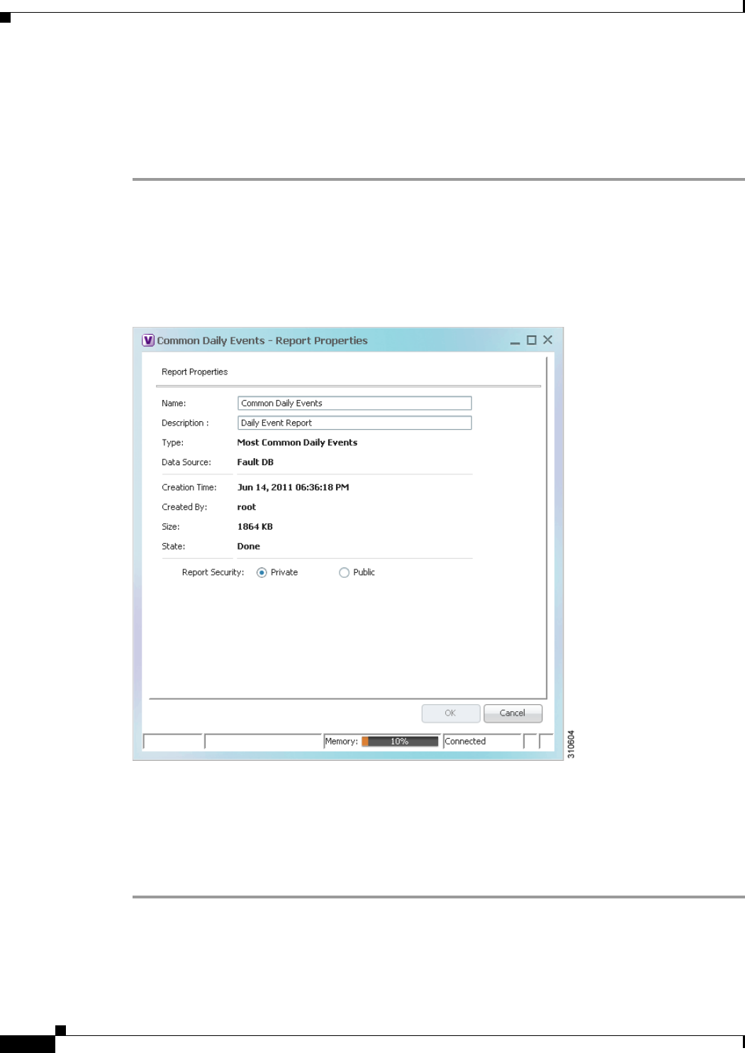
10-44
Cisco Prime Network 4.0 User Guide OL-29343-01
Chapter 10 Working with Reports
Managing Reports
Viewing Report Properties
The Report Properties dialog box enables you to view the report settings and to modify some of them.
To view report properties, and optionally change the name, description, or access:
Step 1 Choose Reports > Report Manager.
Step 2 Locate the required report.
Step 3 In the content pane, right-click the selected report, then choose Properties.
The Report Properties dialog box is displayed, as shown in Figure 10-8.
Figure 10-8 Report Properties Dialog Box
Step 4 Change the information in the following fields as required:
• Name
• Description
• Report Security
Step 5 Click OK.

10-45
Cisco Prime Network 4.0 User Guide
OL-29343-01
Chapter 10 Working with Reports Defining Report Types
Defining Report Types
You can modify any of the report types provided by Prime Network so that it better suits your needs and
environment. This is extremely beneficial if you generate a particular type of report for specific devices
or events on a regular basis.
To define a report type:
Step 1 Choose Reports > Report Manager.
Step 2 In the navigation pane, right-click the existing report type, then choose Define Report of This Type.
Step 3 In the Define report of type dialog box, specify the options using the information in Generating Reports,
page 10-22.
Step 4 In the Location field, use the specified reports folder or click Browse to select a different folder.
Step 5 Click OK.
The newly defined report type appears in the navigation tree in the specified folder.
Managing Report Folders
Prime Network provides the following options for working with report folders:
• Creating Folders, page 10-45
• Moving Folders, page 10-46
• Renaming Folders, page 10-46
• Deleting Folders, page 10-47
• Viewing Folder and Report Type Properties, page 10-47
Creating Folders
Prime Network enables you to create additional report folders in Report Manager.
To create a report folder:
Step 1 Choose Reports > Report Manager.
Step 2 Select a folder in which to place the new folder.
Step 3 Right-click the folder, then choose New Folder.
Step 4 In the New Folder dialog box, enter a name for the folder.
Step 5 Click OK.
The navigation pane is refreshed and the new folder is displayed.

10-46
Cisco Prime Network 4.0 User Guide OL-29343-01
Chapter 10 Working with Reports
Managing Report Folders
Step 6 To move the new folder to another folder, or to the top level in the folder hierarchy:
a. Right-click the folder, then choose Move.
b. In the Move To dialog box, select the location where you want the folder to reside.
c. Click OK.
The folder is displayed in the new location.
Moving Folders
Prime Network enables you to move folders that you have created in Report Manager. You cannot move
the Events Reports, Inventory Reports, or Network Service Reports folder.
To move a report folder:
Step 1 Choose Reports > Report Manager.
Step 2 Right-click the folder, then choose Move.
Step 3 In the Move To dialog box, select the location where you want the folder to reside.
Step 4 Click OK.
The navigation pane is refreshed and the folder is displayed in the new location.
Renaming Folders
Prime Network enables you to rename folders that you have created in Report Manager. You cannot:
• Rename a folder that resides at the highest level in the hierarchy, such as the Events Reports,
Inventory Reports, or Network Service Reports folder.
• Use the same name for different folders that reside at the same level in the hierarchy.
To rename a report folder:
Step 1 Choose Reports > Report Manager.
Step 2 Right-click the folder, then choose Rename.
Step 3 In the Rename Folder dialog box, enter the new name for the folder.
Step 4 Click OK.
The navigation pane is refreshed and the folder is displayed with the new name.

10-47
Cisco Prime Network 4.0 User Guide
OL-29343-01
Chapter 10 Working with Reports Managing Report Folders
Deleting Folders
You can delete folders that you have created in Report Manager if they are empty. You cannot delete the
following folders:
• Events Reports
• Detailed Network Events
• Detailed Non-Network Events
• Inventory Reports
• Network Service Reports
• User-created folders that contain other folders or report types
To delete a report folder:
Step 1 Choose Reports > Report Manager.
Step 2 Right-click the folder, then choose Delete.
Step 3 In the Confirm Folder Delete dialog box, click Yes to confirm the deletion.
The navigation pane is refreshed and the folder no longer appears.
Viewing Folder and Report Type Properties
Viewing Report Folder Properties
The Report Properties window enables you to view report properties and to add folders.
To view report properties:
Step 1 Choose Reports > Report Manager.
Step 2 In the navigation pane, right-click the required folder, then choose Properties.
The Folder Properties window is displayed, as shown in Figure 10-9.
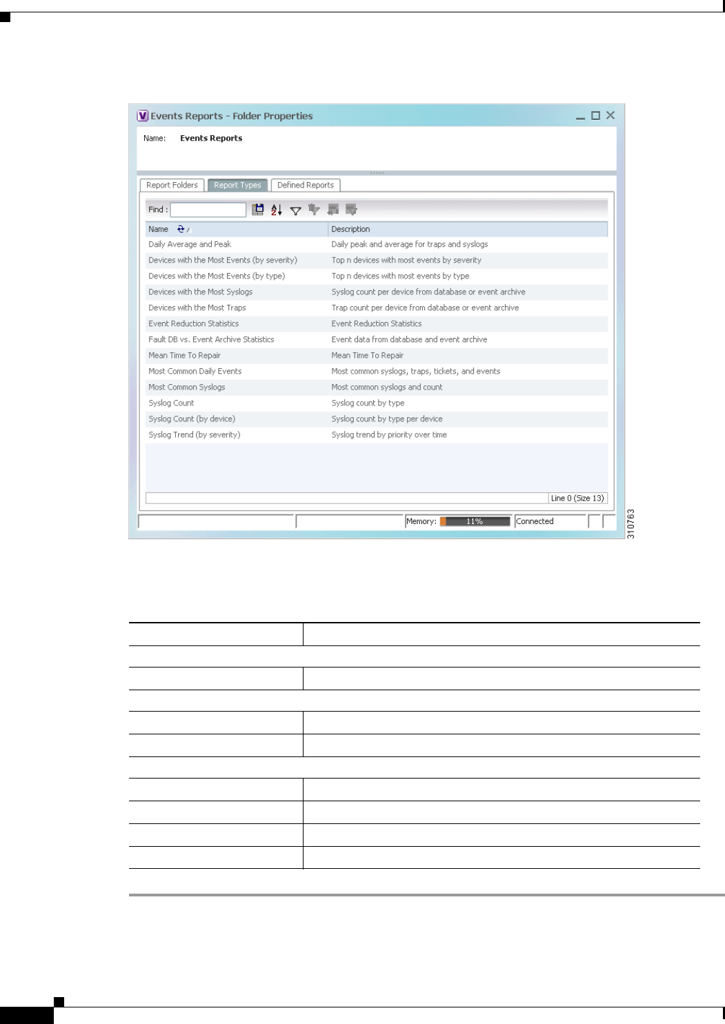
10-48
Cisco Prime Network 4.0 User Guide OL-29343-01
Chapter 10 Working with Reports
Managing Report Folders
Figure 10-9 Folder Properties
Table 10-22 describes the information that is displayed in each tab, depending on the folder’s contents.
Table 10-22 Folder Properties Window
Field Description
Report Folders Tab
Name Name of the folder included in the selected folder.
Report Types Tab
Name Name of the report type included in the selected folder.
Description Description of the report type included in the selected folder.
Defined Reports Tab
Name Name of the user-defined report in the selected folder.
Description Description of the user-defined report in the selected folder.
Type Report type on which the user-defined report is based.
Public Status of public access to the report: True or False.

10-49
Cisco Prime Network 4.0 User Guide
OL-29343-01
Chapter 10 Working with Reports Managing Report Folders
Viewing Report Type Properties
To view report type properties:
Step 1 In the navigation pane, right-click the required report type, then choose Properties.
The information that is displayed depends on whether the report type is one that you defined or one
provided by Prime Network:
• Prime Network-provided report type—The Report Type Properties window is displayed with the
report name and description. Click Run to generate the report.
• User-defined report type—The Edit dialog box is displayed with all settings specified for the report
type. You can modify the settings or leave them as they are.
Step 2 Click Close or the upper right corner to close the window.

10-50
Cisco Prime Network 4.0 User Guide OL-29343-01
Chapter 10 Working with Reports
Managing Report Folders

CHAPTER
11-1
Cisco Prime Network 4.0 User Guide
OL-29343-01
11
Using Cisco PathTracer to Diagnose Problems
Cisco PathTracer enables you to view a network path between two network objects. The following topics
describe Cisco PathTracer and how to use it:
• User Roles Required to Work with Cisco PathTracer, page 11-1
• Cisco PathTracer Overview, page 11-2
• Launching Path Tracer, page 11-3
• Viewing Path Traces in Cisco PathTracer, page 11-14
• Viewing Path Trace Details, page 11-20
• Saving and Opening Cisco PathTracer Map Files, page 11-26
• Saving Cisco PathTracer Counter Values, page 11-26
• Rerunning a Path and Comparing Results, page 11-27
• Viewing Q-in-Q Path Information, page 11-27
• Viewing L2TP Path Information, page 11-28
• Using Cisco PathTracer in MPLS Networks, page 11-29
User Roles Required to Work with Cisco PathTracer
This topic identifies the roles that are required to work with Cisco PathTracer. Cisco Prime Network
(Prime Network) determines whether you are authorized to perform a task as follows:
• For GUI-based tasks (tasks that do not affect elements), authorization is based on the default
permission that is assigned to your user account.
• For element-based tasks (tasks that do affect elements), authorization is based on the default
permission that is assigned to your account. That is, whether the element is in one of your assigned
scopes and whether you meet the minimum security level for that scope.
For more information on user authorization, see the Cisco Prime Network 4.0 Administrator Guide.
The following tables identify the tasks that you can perform:
• Table 11-1 identifies the tasks that you can perform if a selected element is not in one of your
assigned scopes.
• Table 11-2 identifies the tasks that you can perform if a selected element is in one of your assigned
scopes.

11-2
Cisco Prime Network 4.0 User Guide OL-29343-01
Chapter 11 Using Cisco PathTracer to Diagnose Problems
Cisco PathTracer Overview
By default, users with the Administrator role have access to all managed elements. To change the
Administrator user scope, see the topic on device scopes in the Cisco Prime Network 4.0 Administrator
Guide.
Cisco PathTracer Overview
Cisco PathTracer enables you to launch end-to-end route traces and view related performance
information for Layer 1, Layer 2, and Layer 3 traffic. Upon receiving a path's start and endpoint,
Cisco PathTracer visually traces the route through the network. For example, in an ATM network
environment, Cisco PathTracer identifies all information regarding the connection of a subscriber to a
provider, including all ATM PVCs, ATM switching tables, ATM class of service (CoS) definitions,
IP-related information, and so on.
You can also use Cisco PathTracer to:
• Trace paths using IPv4, IPv6, or both IPv4 and IPv6 addresses for the source and destination.
• Trace a hypothetical Ethernet frame from a VLAN interface to a specified MAC address.
• Trace a hypothetical Ethernet frame from an Ethernet interface to a specified MAC address within
a specific VLAN identifier.
Table 11-1 Default Permission/Security Level Required for Working with Cisco PathTracer -
Element Not in User’s Scope
Task Viewer Operator OperatorPlus Configurator Administrator
Launch a path trace — — — — X
View path information — — — — X
Save Cisco PathTracer
map files ————X
Save Cisco PathTracer
counter values ————X
Rerun a path and
compare results ————X
Table 11-2 Default Permission/Security Level Required for Working with Cisco PathTracer -
Element in User’s Scope
Task Viewer Operator OperatorPlus Configurator Administrator
Launch a path trace — X X X X
View path information — X X X X
Save Cisco PathTracer
map files —XXXX
Save Cisco PathTracer
counter values —XXXX
Rerun a path and
compare results —XXXX

11-3
Cisco Prime Network 4.0 User Guide
OL-29343-01
Chapter 11 Using Cisco PathTracer to Diagnose Problems Launching Path Tracer
In MPLS and Carrier Ethernet environments, Cisco PathTracer can trace paths across:
• Carrier Supporting Carrier (CSC) configurations—A path trace along a CSC flow follows the path
from the customer CE through the customer carrier VPN, across the customer backbone carrier
VPN, back to the customer carrier VPN, and to the destination CE.
• VLANs—A path trace across VLANs follows the path based on the forwarding table, which means
that the trace follows ports in the Forwarding STP state.
• Q-in-Q—A path trace across Q-in-Q creates a single path trace (if the MAC address is learned) or a
multiple-path (multipath) trace if the MAC address is not in the forwarding table. If the VLAN
bridge has not learned a given MAC address, the bridge floods the Ethernet frame to the confines of
a given VLAN or switching entity and across those ports that allow the given VLAN identifier. A
MAC/VLAN path trace can be conducted from a customer edge (CE) VLAN interface across a
service provider (SP) VLAN; that is, across Q-in-Q configurations with the CE-VLAN identifier as
the inner VLAN identifier and Cisco PathTracer detecting the outer SP-VLAN identifier that
encapsulates the CE-VLAN.
• Pseudowires (also known as EoMPLS)—A MAC/VLAN path trace can be conducted from a VLAN
interface across a VLAN attachment to a pseudowire.
• VLAN-VPLS-VLAN configurations—A multiple-point MAC/VLAN path trace can be conducted
on CE-VLANs across a service provider VPLS transport from a VLAN interface that attaches to the
VPLS.
In addition, Cisco PathTracer can trace a path:
• If the destination MAC address is not reachable—If Cisco PathTracer cannot complete a
MAC/VLAN path trace to a specified destination MAC address across an MPLS core, VPLS, or
H-VPLS, then Cisco PathTracer displays the portion of the path that Cisco PathTracer can trace
toward the destination MAC address.
• That contains a simulated Ethernet frame—Cisco PathTracer can trace a simulated Ethernet frame
from a VLAN port, across a VLAN (VLAN-based flow domain fragment), VPLS (VPLS-based flow
domain fragment), and VLAN, for an end-to-end MAC address trace.
Prime Network derives the various paths on the network from its up-to-date knowledge of the network.
After a user selects a source and destination, Cisco PathTracer finds and retrieves the path of a specified
service, and displays the path in the Cisco PathTracer window. The retrieved information contains
network elements in the path, including all properties at Layer 1, Layer 2, and Layer 3, plus alarm
information, counters, and more, all of which is available via Cisco PathTracer.
Launching Path Tracer
Cisco PathTracer can be launched from a bridge, switching entity, Ethernet interface, Ethernet flow
point, VLAN interface, ATM VC, DLCI, or IP interface entry point. Ethernet flow points can be starting
points whether they are associated with an interface, bridge, or LAG.
The virtual route is found according to the cross connect table of each ATM switch or Frame Relay
device. The IP routing and path-finding process is enabled according to the VRF tables of each router,
and the Ethernet-simulated path is found according to the various Layer 2 forwarding tables, such as
bridges or VSIs.

11-4
Cisco Prime Network 4.0 User Guide OL-29343-01
Chapter 11 Using Cisco PathTracer to Diagnose Problems
Launching Path Tracer
To view a specific path, you must specify an initial point and a destination, such as an IP or MAC
address. If you specify VC or DLCI information, which ends in a router, Cisco PathTracer finds the next
hop according to the destination IP address. If you do not specify a destination IP or MAC address,
Cisco PathTracer uses the default gateway in the router. Any business tags that are associated with the
physical or logical entities are also displayed.
Note A path can also be launched if a business tag attached to an endpoint that can be used as the starting
point.
Path Traces and Blocked Ports
The following conditions apply for blocked ports:
• You can launch a path trace from a blocked port. This action is equivalent to launching a path trace
from a bridge.
• You can specify a blocked port as a destination.
• If Cisco PathTracer encounters a blocked port in its path to the destination, the path trace stops. Path
traces do not traverse blocked ports.
Table 11-3 identifies the available path trace launching points and their locations within Cisco Prime
Network Vision. Cisco PathTracer is available in each location as a right-click menu option.
Cisco PathTracer Right-Click Menu Options
Cisco PathTracer is launched by using right-click menu options. Table 11-3 identifies the launching
points for the different types of elements.
Table 11-3 Cisco PathTracer Right-Click Menu Options
Element Location
Affected Parties • Inventory window
• Ticket Properties window (Affected Parties tab)
Bridge Inventory window
Business tag The path can be found using a business tag, which is attached to the
VPI/VCI, or using an IP interface by entering its key. The path can
then be opened from the Find Business Tag dialog box.
Ethernet flow point • Map view or navigation pane
• Inventory window
IP interface • Inventory window
• Affected entry
Layer 2 MPLS tunnel Inventory window
MPLS-TE tunnel Inventory window
MPLS-TP tunnel endpoint • Map view or navigation pane
• Inventory window
Port Inventory window

11-5
Cisco Prime Network 4.0 User Guide
OL-29343-01
Chapter 11 Using Cisco PathTracer to Diagnose Problems Launching Path Tracer
Starting a Path Trace
You can start a path trace in the following ways:
• From the Map View, page 11-5
• From Logical or Physical Inventory, page 11-7
From the Map View
To start a path trace from the map view:
Step 1 In a Cisco Prime Network Vision map, start the path trace in one of the following ways:
• For a VLAN:
a. In the navigation pane or map pane, select the required network VLAN.
b. Double-click the VLAN to view the VLAN entities.
c. Right-click the required item and choose PathTracer > From Here to Destination or
PathTracer > Start Here.
• For a VPN:
a. In the navigation pane or map pane, select the required network VPN.
b. Double-click the VPN to view the VPN entities.
c. Right-click the site and choose PathTracer > From Here to Destination or PathTracer > Start
Here.
• For an Ethernet flow point:
a. Choose Network Inventory > Ethernet Flow Domains.
b. In the Ethernet Flow Domain List Properties window, double-click the required domain.
c. In the Ethernet Flow Domain Properties window, right-click the required element and choose
PathTracer > From Here to Destination or PathTracer > Start Here.
Pseudowire endpoint • Map view or navigation pane
• Inventory window
Site Map view
Switching entity Map view
Virtual connection Inventory window:
• Cross Connect window
• VC Table window
VLAN • Navigation pane
• Map view
Table 11-3 Cisco PathTracer Right-Click Menu Options (continued)
Element Location
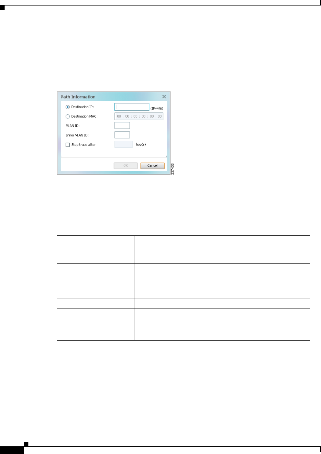
11-6
Cisco Prime Network 4.0 User Guide OL-29343-01
Chapter 11 Using Cisco PathTracer to Diagnose Problems
Launching Path Tracer
The next step depends on your choice in Step 1:
• If you choose PathTracer > From Here to Destination, the Path Information dialog box is
displayed (Figure 11-1). Continue with Step 2.
• If you choose PathTracer > Start Here, continue with Step 3.
Figure 11-1 Path Information Dialog Box
Step 2 To specify a destination:
a. In the Path Information dialog box, enter the required information, as described in Table 11-4.
Depending on the launch point, the Path Information dialog box might not contain all of the fields
in Table 11-4.
b. Click OK.
Step 3 If you choose Start Here, navigate to the destination interface, port, or bridge, right-click it, and choose
End Here.
The Cisco PathTracer window is displayed showing the path or paths that were found.
Step 4 To view additional details regarding the path traces, select one or more paths in the paths pane.
Table 11-4 Cisco PathTracer Path Information Dialog Box
Field Description
Destination IP Select this option to specify an IP address as the destination. Enter
either an IPv4 or IPv6 address.
Destination MAC Select this option to specify a MAC address as the destination. Enter
the MAC address.
VLAN ID Enter the required VLAN identifier. You must enter an IP address or
a MAC address to use this option.
Inner VLAN ID Enter the required inner VLAN identifier.
Stop trace after Check this check box to limit the number of hops that
Cisco PathTracer makes in its attempt to reach the destination.
Enter the maximum number of hops that you want to allow in the
hops field.

11-7
Cisco Prime Network 4.0 User Guide
OL-29343-01
Chapter 11 Using Cisco PathTracer to Diagnose Problems Launching Path Tracer
Step 5 In the toolbar, click Cisco PathTracer.
• If you select one or more paths in the paths pane, each selected path is displayed in its own window
with the Layer 1, Layer 2, Layer 3, and Business Tag tabs.
• If you select nothing in the Paths pane, each path found is displayed in its own window with the
Layer 1, Layer 2, Layer 3, and Business Tag tabs.
For more information about the end-to-end path and networking layer details, see Viewing Path Trace
Details, page 11-20.
From Logical or Physical Inventory
To start a path trace from logical or physical inventory:
Step 1 Open the inventory window for the required device.
Step 2 Select one of the following launch points in logical or physical inventory:
• IP interface
• MPLS-TP tunnel endpoint
• Port
• Pseudowire endpoint
• VLAN bridge
Step 3 Right-click the selected item and choose one of the following:
• PathTracer > From Here to Destination—If you choose this option, continue with Step 2 in From
the Map View, page 11-5.
Note If you select an IP interface as the launch point, the right-click menu displays IPv4 and IPv6
options. These options are enabled or dimmed, depending on whether the IP interface has an
IPv4 IP address, an IPv6 address, or both IPv4 and IPv6 addresses. For an example, see
Figure 11-3.
• PathTracer > Start Here—If you choose this option, continue with Step 3 in From the Map View,
page 11-5.
Examples of Launching Cisco PathTracer
The following topics provide examples for launching Cisco PathTracer from different locations in
Cisco Prime Network Vision:
• Using an Ethernet Flow Point, page 11-8
• Using an IP Interface, page 11-9
• Using a VLAN Bridge, page 11-10
• Using an Ethernet Port, page 11-12
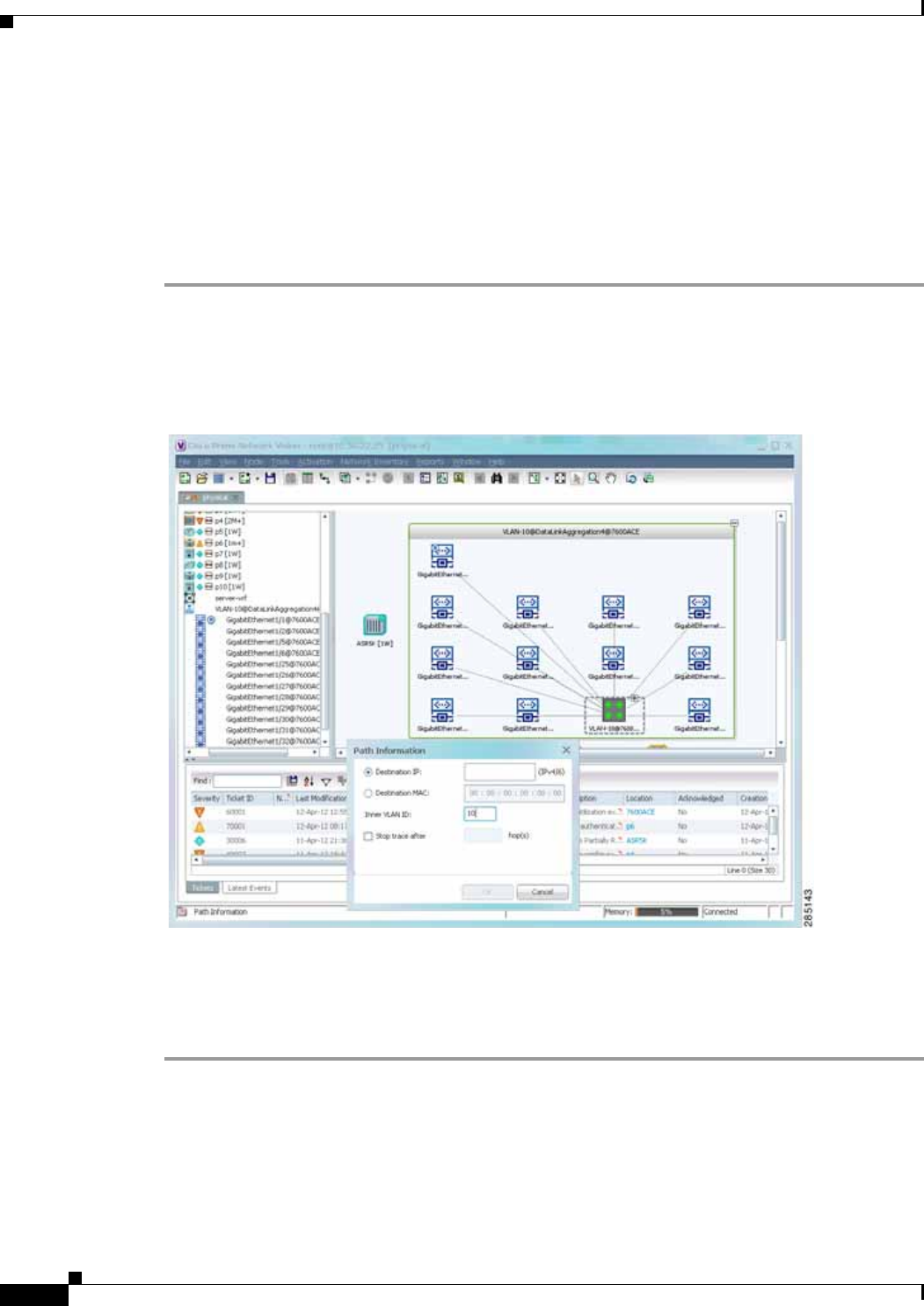
11-8
Cisco Prime Network 4.0 User Guide OL-29343-01
Chapter 11 Using Cisco PathTracer to Diagnose Problems
Launching Path Tracer
• Using a Pseudowire, page 11-12
• Using an MPLS-TP Tunnel Endpoint, page 11-13
Using an Ethernet Flow Point
A network VLAN is required for you to start a path trace using an Ethernet flow point.
To launch a path trace from an Ethernet flow point:
Step 1 In the Cisco Prime Network Vision navigation pane or map pane, expand the required network VLAN.
Step 2 In the VLAN, right-click the required Ethernet flow point and choose PathTracer > From Here to
Destination. The Path Information dialog box is displayed as shown in Figure 11-2.
Figure 11-2 Ethernet Flow Point Path Trace Launch Point
Step 3 Specify the destination using the information in Table 11-4.
Step 4 To limit the number of hops for the path trace, check the Stop trace after check box, and enter the
maximum number of hops for the path trace.
Step 5 Click OK. The Cisco PathTracer window is displayed with the resulting path trace.
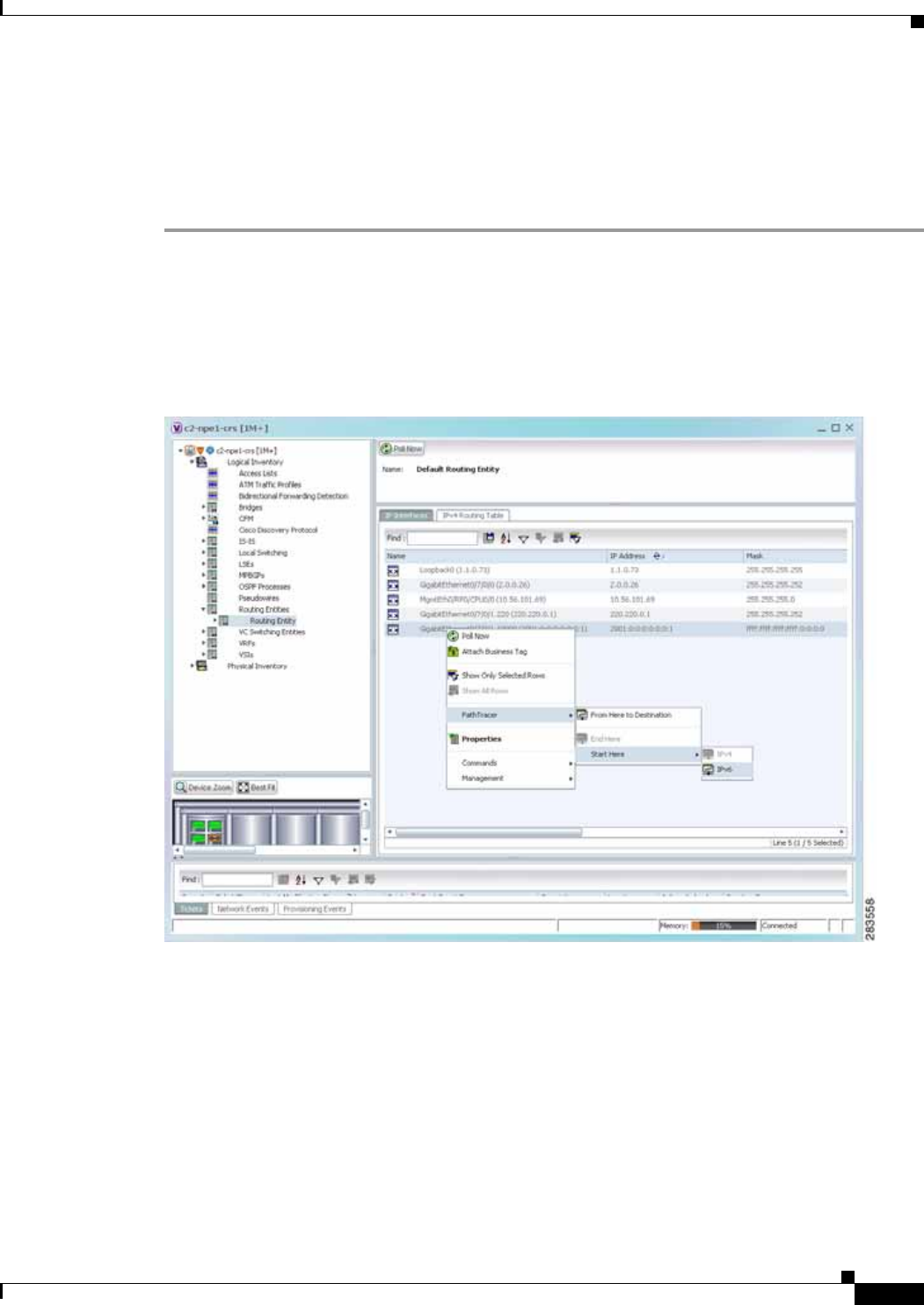
11-9
Cisco Prime Network 4.0 User Guide
OL-29343-01
Chapter 11 Using Cisco PathTracer to Diagnose Problems Launching Path Tracer
Using an IP Interface
Both IPv4 and IPv6 addresses are supported as valid path trace sources and destinations as illustrated in
the following procedure.
To launch a path trace from an IP interface:
Step 1 In logical inventory, right-click the required IP interface (Logical Inventory > Routing
Entities > Routing Entity > ip-interface).
The right-click menu displays IPv4 and IPv6 options. These options are enabled or dimmed, depending
on whether the IP interface has an IPv4 address, an IPv6 address, or both IPv4 and IPv6 addresses. See
Figure 11-3.
Figure 11-3 IP Interface Path Trace Launch Point - Right-Click Menu
Step 2 Choose PathTracer > From Here to Destination.
The Path Information dialog box is displayed as shown in Figure 11-4.
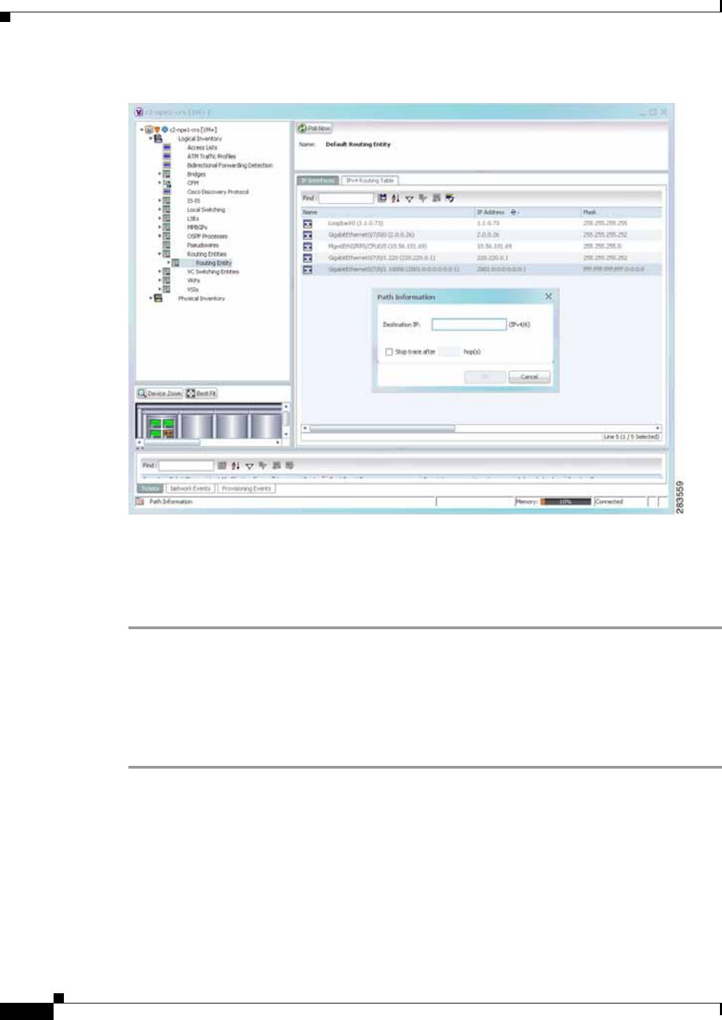
11-10
Cisco Prime Network 4.0 User Guide OL-29343-01
Chapter 11 Using Cisco PathTracer to Diagnose Problems
Launching Path Tracer
Figure 11-4 IP Interface Path Trace Launch Point - Path Information Dialog Box
Step 3 In the Destination IP field, enter the IPv4 or IPv6 address.
Step 4 To limit the number of hops for the path trace, check the Stop trace after check box, and enter the
maximum number of hops for the path trace.
Step 5 Click OK. The Cisco PathTracer window appears, displaying the resulting path trace.
Using a VLAN Bridge
You can launch path traces from VLAN bridges. Additionally, MAC addresses in the VLAN bridge
forwarding table can be path trace destinations.
To launch a path trace from a VLAN bridge:
Step 1 In logical inventory, right-click the required bridge (Logical Inventory > Bridges > bridge) and choose
one of the following options as shown in Figure 11-5:
• PathTracer > From Here to Destination
• PathTracer > Start Here
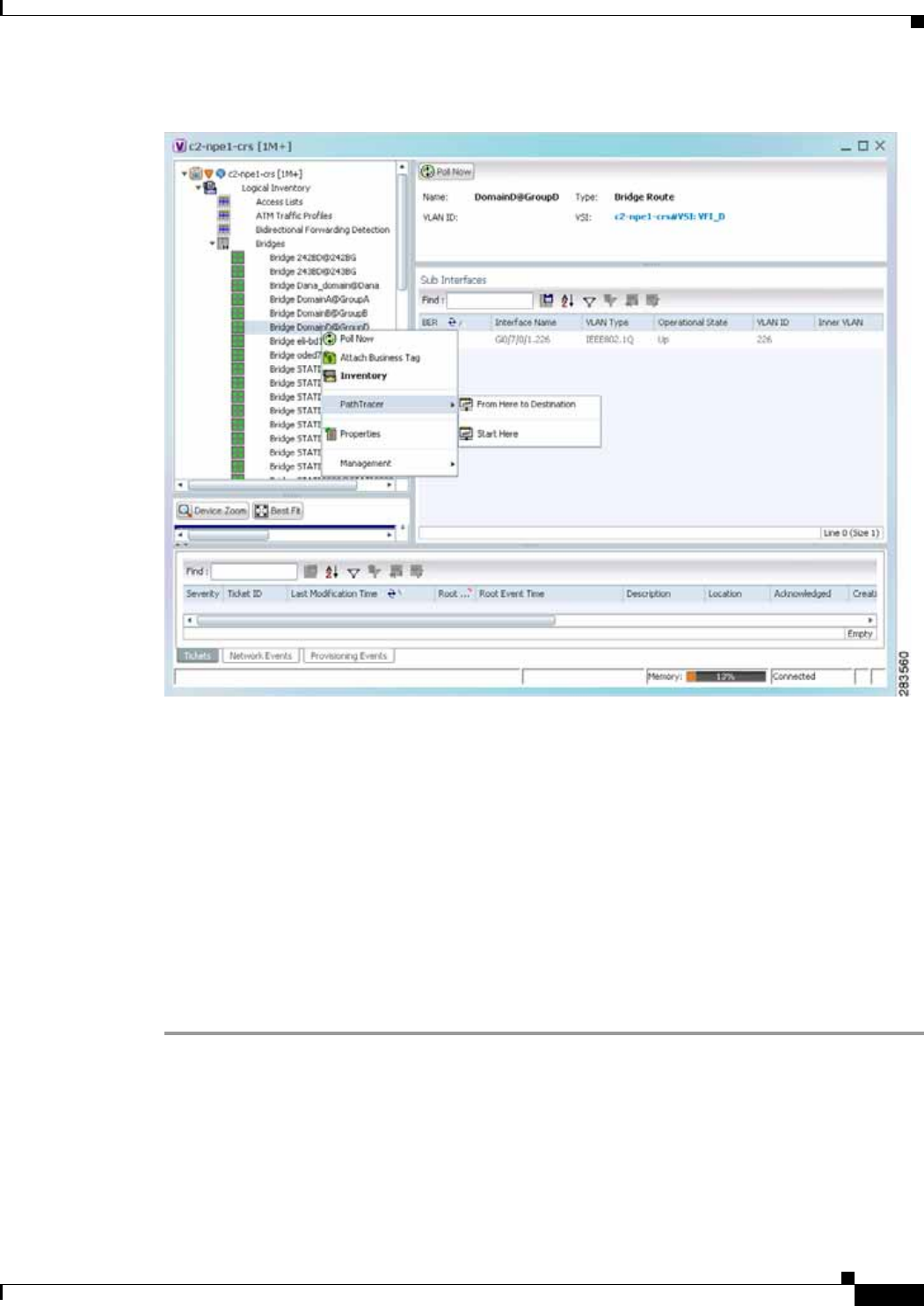
11-11
Cisco Prime Network 4.0 User Guide
OL-29343-01
Chapter 11 Using Cisco PathTracer to Diagnose Problems Launching Path Tracer
Figure 11-5 VLAN Bridge Path Trace Launch Point
Step 2 If you choose From Here to Destination in Step 1, the Path Information dialog box is displayed.
Specify the required destination using the information in Table 11-4.
Step 3 If you choose Start Here, navigate to the destination, right-click it, and choose End Here. Destination
options include:
• IP interface—Logical Inventory > Routing Entities > Routing Entity > IP-interface
• Bridge—Logical Inventory > Bridges > bridge
• MAC address—Logical Inventory > Bridges > bridge > Bridge Table > MAC-address
• Ethernet port—Physical Inventory > chassis > slot > port
When a destination is selected, the system extracts the relevant IP address from this point and uses it as
the destination.
The Cisco PathTracer window is displayed with the resulting path trace.
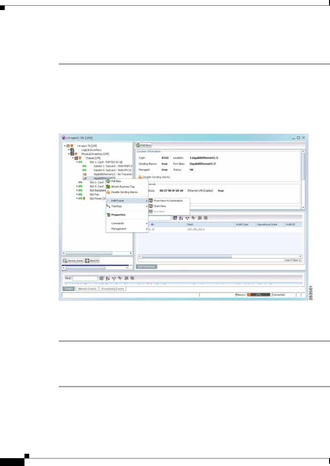
11-12
Cisco Prime Network 4.0 User Guide OL-29343-01
Chapter 11 Using Cisco PathTracer to Diagnose Problems
Launching Path Tracer
Using an Ethernet Port
To launch a path trace from an Ethernet port:
Step 1 In physical inventory, right-click the required port (Physical
Inventory > Chassis > slot > subslot > port) and choose one of the following options as shown in
Figure 11-6:
• PathTracer > From Here to Destination
• PathTracer > Start Here
Figure 11-6 Ethernet Port Path Trace Launch Point
Step 2 Depending on your choice in Step 1, specify the required destination information or select the path trace
endpoint.
The Cisco PathTracer window appears, displaying the resulting path trace.
Using a Pseudowire
To launch a path trace from a network pseudowire endpoint:
Step 1 In the navigation pane or map pane, expand the required network pseudowire.
Step 2 Right-click the required pseudowire endpoint and choose PathTracer > From Here to Destination.
The Path Information dialog box is displayed as shown in Figure 11-7.
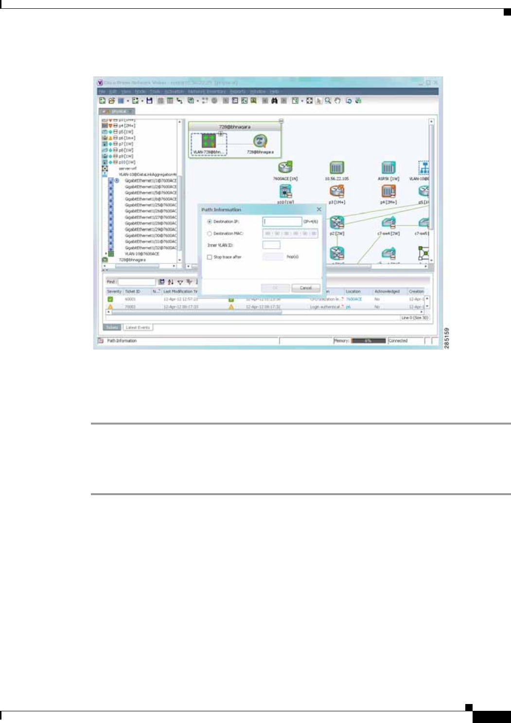
11-13
Cisco Prime Network 4.0 User Guide
OL-29343-01
Chapter 11 Using Cisco PathTracer to Diagnose Problems Launching Path Tracer
Figure 11-7 Path Information Dialog Box for a Network Pseudowire
Step 3 Specify the destination using the information in Table 11-4.
Step 4 To limit the number of hops for the path trace, check the Stop trace after check box, and enter the
maximum number of hops for the path trace.
The Cisco PathTracer window appears, displaying the resulting path trace.
Using an MPLS-TP Tunnel Endpoint
To launch a path trace from an MPLS-TP tunnel endpoint:
Step 1 In the navigation pane or map pane, expand the required MPLS-TP tunnel.
Step 2 Right-click the required MPLS-TP tunnel endpoint and choose PathTracer > From Here to
Destination.
The Path Information dialog box is displayed as shown in Figure 11-8.
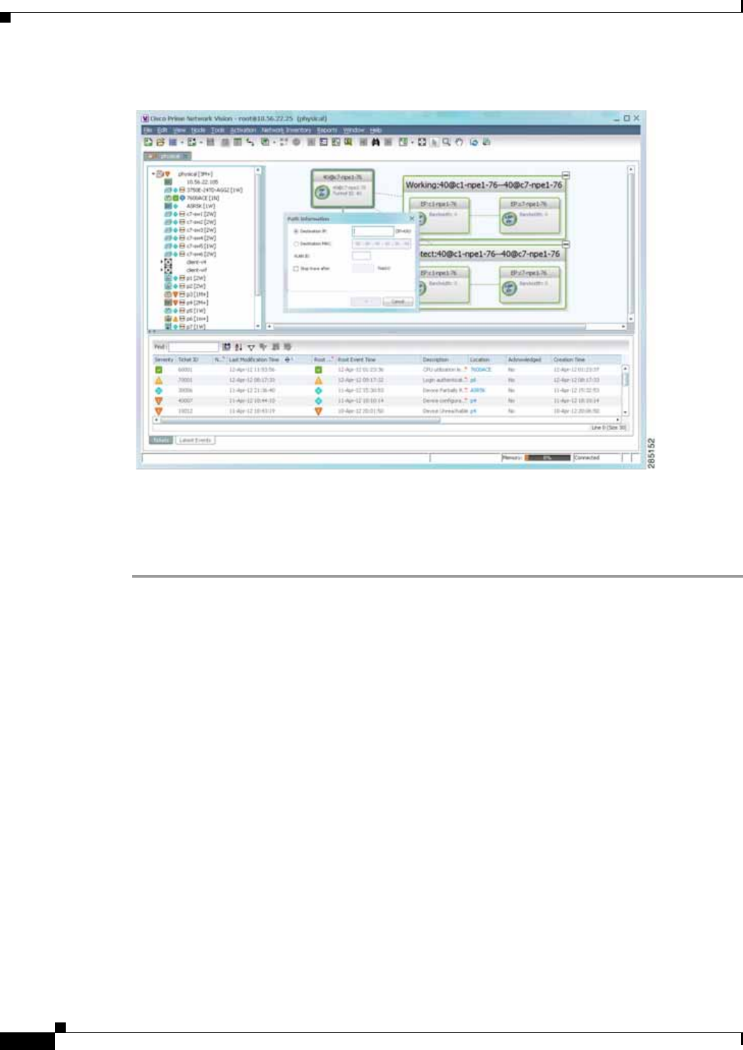
11-14
Cisco Prime Network 4.0 User Guide OL-29343-01
Chapter 11 Using Cisco PathTracer to Diagnose Problems
Viewing Path Traces in Cisco PathTracer
Figure 11-8 MPLS-TP Tunnel Endpoint Path Trace Launch
Step 3 Specify the destination using the information in Table 11-4.
Step 4 To limit the number of hops for the path trace, check the Stop trace after check box, and enter the
maximum number of hops for the path trace.
The Cisco PathTracer window appears, displaying the resulting path trace.
Viewing Path Traces in Cisco PathTracer
The Cisco PathTracer window displays all discovered paths for the specified source and destination of
the path trace, including the devices and physical links.
In addition, the Cisco PathTracer window enables you to:
• Zoom in and out on path traces by using your mouse scroll wheel.
• Apply one of four icon sizes to icons.
• View more or less information about the element by resizing the icon.
• Access common functions from the icons, such as attaching business tags or viewing properties.
You can also right-click elements in the Cisco PathTracer window and choose options from a right-click
menu. The right-click menu is context sensitive depending on the view and the item selected. For more
information about the right-click menu and the available options, see Right-Click Menu Options,
page 11-19.
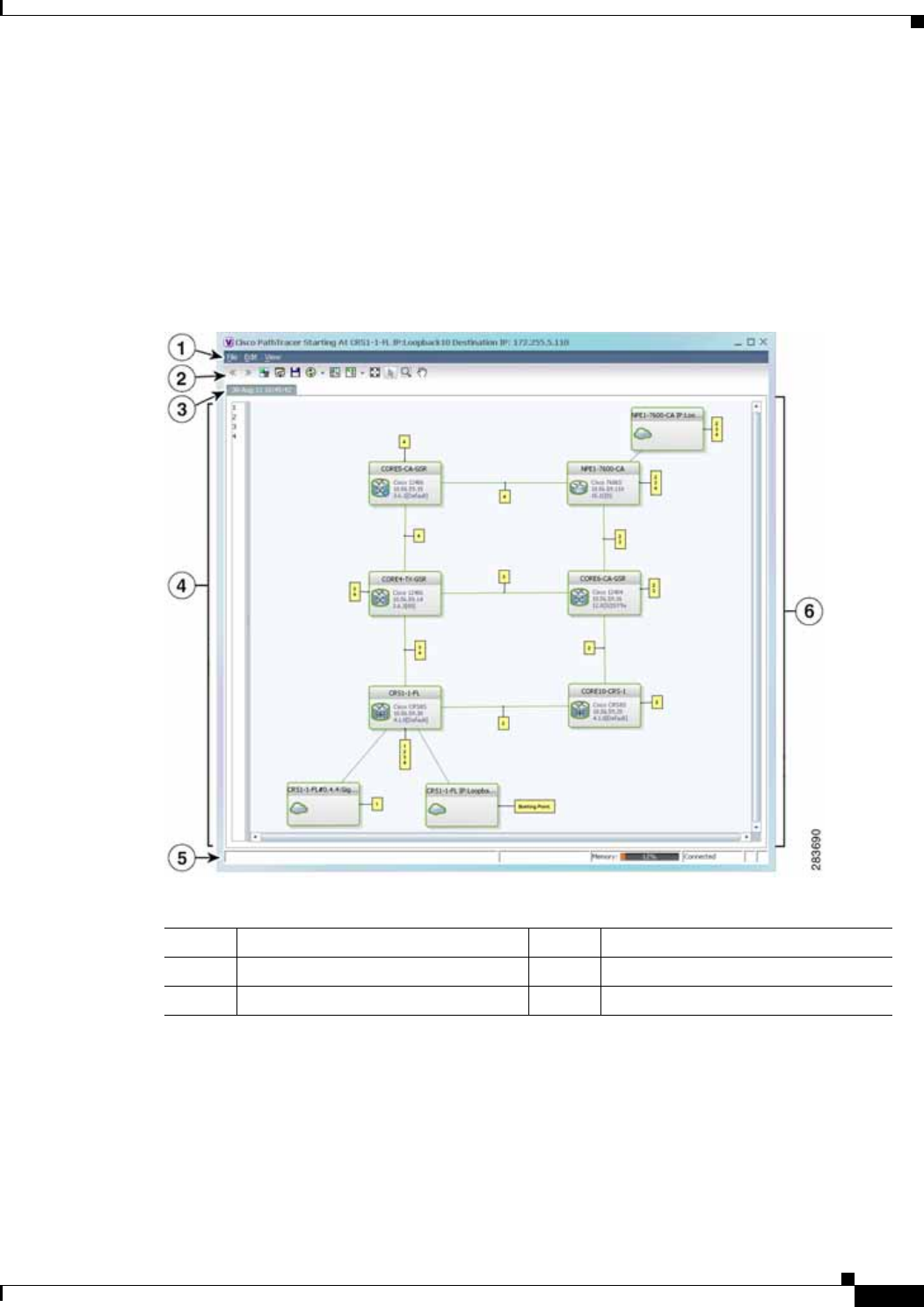
11-15
Cisco Prime Network 4.0 User Guide
OL-29343-01
Chapter 11 Using Cisco PathTracer to Diagnose Problems Viewing Path Traces in Cisco PathTracer
The Cisco PathTracer window enables you to:
• View multiple paths for a selected source and destination either sequentially or simultaneously.
• View individual paths with networking layer details.
• Save a map with multiple paths to a file.
• Run Cisco PathTracer again, using the same trace or with a different limit number of hops.
Figure 11-9 shows an example of the Cisco PathTracer window with a multiple-path trace.
Figure 11-9 Cisco PathTracer Window - Multiple-Path Trace
The Cisco PathTracer window contains the following components and options:
• Menus, page 11-16
• Toolbar, page 11-17
• Trace Tabs, page 11-18
• Paths Pane, page 11-18
1Menu bar 4Paths pane
2Toolbar 5Status bar
3Trace tabs 6Path trace pane

11-16
Cisco Prime Network 4.0 User Guide OL-29343-01
Chapter 11 Using Cisco PathTracer to Diagnose Problems
Viewing Path Traces in Cisco PathTracer
• Path Trace Pane, page 11-18
• Right-Click Menu Options, page 11-19
Menus
Table 11-5 describes the options available in the Cisco PathTracer menus.
Table 11-5 Cisco PathTracer Window Menu Options
Option Description
File Menu
Run Again Offers the following options for running Cisco PathTracer again for the same
source and destination:
• Change Hop Count—Enables you to enter a new hop count.
• Repeat Last Trace—Runs the previous trace with the same settings.
• Run Full Path Trace—Runs the previous trace without a hop count limit.
Save Opens the Save dialog box so that you can save the current path trace to your
local system in XML format.
Close Closes the Cisco PathTracer window.
Edit Menu
Select All Selects all paths in the selected path trace pane.
View Menu
Layout Specifies how the elements are arranged in the path trace pane: circular,
hierarchical, orthogonal, or symmetric.
Overview Opens a window displaying an overview of the path trace.
Zoom In Zooms in on the current path trace.
Zoom Out Zooms out on the current path trace.
Fit in Window Fits the entire path trace in the path trace pane.
Normal Select Activates the normal selection mode.
Pan Activates the pan mode, which enables you to move around in the path trace by
clicking and dragging.
Zoom Selection Enables you to zoom in on a specific area in the path trace.
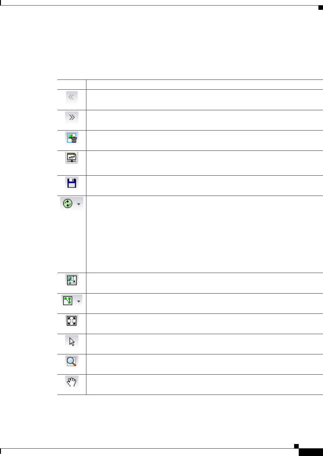
11-17
Cisco Prime Network 4.0 User Guide
OL-29343-01
Chapter 11 Using Cisco PathTracer to Diagnose Problems Viewing Path Traces in Cisco PathTracer
Toolbar
Table 11-6 describes the options available in the Cisco PathTracer toolbar.
Table 11-6 Cisco PathTracer Toolbar Options
Button Function
Displays the previous path in the path trace pane.
Displays the next path in the path trace pane.
Clears the path selection made in the path trace pane.
Opens the Cisco PathTracer details window. A map is displayed for the selected path,
including network element details, links, and property information. For more information,
see Viewing Path Trace Details, page 11-20.
Saves the current multiple-path trace to an XML file on your local system. For more
information, see Saving and Opening Cisco PathTracer Map Files, page 11-26.
Offers the following options for running Cisco PathTracer again for the same source and
destination:
• Change Hop Count—Enables you to enter a new hop count.
• Repeat Last Trace—Runs the previous trace with the same settings.
• Run Full Path Trace—Runs the previous trace without a hop count limit.
The new path trace map is displayed in the path trace pane.
A new tab with the up-to-date (or refreshed) path map is created for each run, with each tab
representing a run and the tab label indicating the snapshot time.
Opens a window displaying a high level view of the path trace currently displayed in the
path trace pane.
Specifies how the elements are arranged in the path trace pane: circular, hierarchical,
orthogonal, or symmetric.
Fits the entire path trace in the path trace pane.
Activates the normal selection mode. The button toggles when selected or deselected.
Activates the zoom selection mode, which enables you to select a specific area in the path
to zoom in on by clicking and dragging. The button toggles when selected or deselected.
Activates the pan mode, which enables you to move around in the path trace by clicking and
dragging. The button toggles when selected or deselected.

11-18
Cisco Prime Network 4.0 User Guide OL-29343-01
Chapter 11 Using Cisco PathTracer to Diagnose Problems
Viewing Path Traces in Cisco PathTracer
Trace Tabs
The discovered path trace is initially displayed in the path trace pane with a tab that displays the date
and time when Prime Network started the path tracing process (snapshot time).
If you load a saved path from a file or run the displayed path trace again, the opened or refreshed path
is displayed in a new tab with a refreshed path map for each run or file. When using a saved path from
a file, the source and destination must be the same as the current display for it to appear in the same path
trace window. Each tab represents a run or file, and its header displays the snapshot time.
Paths Pane
The paths pane lists all the paths discovered in the current path trace. A new path is created for each
source and destination pair. The paths are identified by number, such as 1, 2, and 3.
If you launch a path trace with a specific hop count, the paths pane displays First n Hops where n is the
number of hops specified.
Selecting a path in the paths pane highlights the selected path in the path trace pane. The paths that are
not selected are dimmed in the map.
To view a different path, do either of the following:
• Choose a different path in the paths pane.
• Click Select Previous Path or Select Next Path in the toolbar.
To remove a path selection, click Clear Path Selection in the toolbar.
Path Trace Pane
The path trace pane displays the devices, links, and topological paths that are part of the path trace. All
links and nodes in the path trace pane are labeled with their relevant path numbers, corresponding to the
numbers in the paths pane. The starting point is labeled with a Starting Point callout. All other edge
points are displayed as clouds.
The same coloring conventions that are used for links in the Prime Network content pane are used to
display links in the Cisco PathTracer path trace pane.
Cisco PathTracer uses icons to display the network objects and their status. The status of a network
object can be indicated on the topological map in the following ways:
• Severity
• Management state
• New alarms
For more information, see:
• Prime Network Vision Status Indicators, page 2-17
• Chapter 2, “Working with the Prime Network Vision Client”
• Map View, page 2-8

11-19
Cisco Prime Network 4.0 User Guide
OL-29343-01
Chapter 11 Using Cisco PathTracer to Diagnose Problems Viewing Path Traces in Cisco PathTracer
Right-Click Menu Options
You can right-click network elements in the path trace window and choose items from a right-click
menu. The right-click menu is context sensitive depending on the view and the element selected.
Table 11-7 describes the right-click menu options that are available for elements selected in the
Cisco PathTracer window.
Table 11-7 Cisco PathTracer Element Right-Click Menu Options
Option Description
Inventory Opens the inventory window for the selected element.
Aggregate Groups the selected devices into an aggregation.
Disaggregate Ungroups the devices in the selected aggregation.
Note This option is available only when an aggregation is selected.
Poll Now Polls the selected element.
Attach Business Tag Attaches a business tag to the selected network element
Config Mgmnt Displays the Configuration Management page for the selected device in
Prime Network Change and Configuration Management. For more
information, see Chapter 4, “Device Configurations and Software Images.”
Image Mgmnt Displays the Configuration Management page for the selected device in
Prime Network Change and Configuration Management. For more
information, see Chapter 4, “Device Configurations and Software Images.”
Resize Enables you to resize an object on the map by percentage or size.
Open Relevant Maps Displays the Open Map dialog box so that you can view and open maps that
contain the selected element.
Run Report Enables you to run standard or user-defined events, inventory, and network
service reports on demand.
Show Callouts/
Hide Callouts Displays or hides callouts associated with the selected element.
Tools Contains the following choices:
• CPU Usage—Displays memory and CPU usage information for a device
or network element.
• Ping—Pings the device from the client station.
• Telnet—Communicates with the device using the Telnet window from
the client station.
Note If you use a Windows 7 system, you must enable the Windows Telnet
Client before you can use the Prime Network Vision Telnet option.
- For Windows 7 32-bit systems, enable the Windows Telnet Client
to use the Prime Network Vision Telnet option.
- For Windows 7 64-bit systems, a solution is available on the
Cisco Developer Network at
http://developer.cisco.com/web/prime-network/
forums/-/message_boards/message/2780108.

11-20
Cisco Prime Network 4.0 User Guide OL-29343-01
Chapter 11 Using Cisco PathTracer to Diagnose Problems
Viewing Path Trace Details
Viewing Path Trace Details
In addition to the information displayed in the Cisco PathTracer window, you can:
• View the following information for each network element:
–
The relevant parameters for each interface on all layers along the path.
–
For each layer, an indication of a mismatch between the parameters of the interfaces on both
sides of a link.
–
Traffic statistics along the path.
• Monitor the status and traffic of all links along the path.
• View In and Out port properties.
To view this information, select the required path in the Cisco PathTracer window, and then click
PathTracer in the toolbar. If you select multiple paths, a separate window is opened for each path.
Figure 11-10 shows an example of the Cisco PathTracer details window.
Topology Enables you to add:
• A static link between two devices.
• A static topology between a device and an unmanaged network.
• A tunnel to a VPN.
Launch external
applications Starts an external application or tool that has been configured for access via
the right-click menu. For more information, see the Cisco Prime Network 4.0
Customization Guide.
Properties Displays the properties of the selected item, such as the IP address and
system name.
Commands Launches available activation and configuration scripts. This can include the
commands documented in Setting Up Devices and Validating Device
Information, page 1-4, and those you create using Command Builder. For
more information, see the Cisco Prime Network 4.0 Customization Guide.
Management Contains the following submenu options:
• Command Builder—Defines commands and scripts using the Prime
Network Command Builder tool (Configurator security level required).
• Soft Properties Management—Extends VNEs by adding SNMP MIB or
Telnet/SHH/TL-1 properties to the device’s collected information model
using the Prime Network Soft Properties Manager (Administrator
security level required).
VNE Tools Contains the following submenu options:
• Poll Now—Updates the VNE information.
• Stop VNE—Stops the VNE.
• Start VNE—Starts the VNE.
Table 11-7 Cisco PathTracer Element Right-Click Menu Options (continued)
Option Description
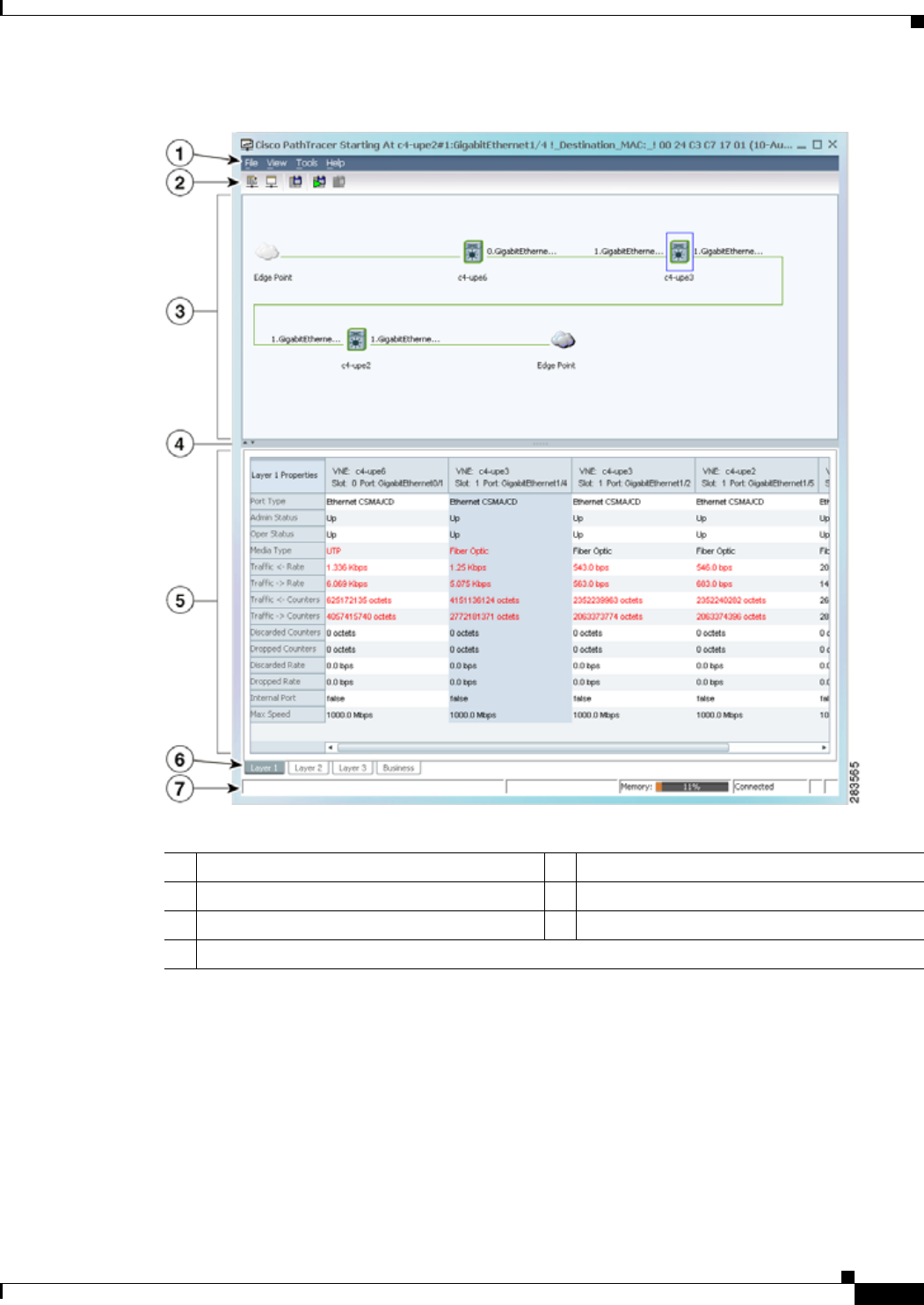
11-21
Cisco Prime Network 4.0 User Guide
OL-29343-01
Chapter 11 Using Cisco PathTracer to Diagnose Problems Viewing Path Trace Details
Figure 11-10 Cisco PathTracer Details Window
The Cisco PathTracer details window contains the following components:
• Menus, page 11-22
• Cisco PathTracer Details Window Toolbar, page 11-22
• Path Trace Pane, page 11-23
• Details Pane, page 11-25
1Menu bar 5Details pane
2Toolbar 6Layer and Business tabs
3Path trace pane 7Status bar
4Hide/display path trace pane

11-22
Cisco Prime Network 4.0 User Guide OL-29343-01
Chapter 11 Using Cisco PathTracer to Diagnose Problems
Viewing Path Trace Details
Menus
Table 11-8 describes the Cisco PathTracer details window menu options.
Cisco PathTracer Details Window Toolbar
Table 11-9 describes the tools that are available in the Cisco PathTracer details window toolbar.
Table 11-8 Cisco PathTracer Details Window Menus
Option Description
File Menu
Close Closes the Cisco PathTracer window.
View Menu
Show All Displays all the information in the tabs.
Hide All Hides all the information in the tabs.
Tools Menu
Export to File Exports the currently displayed data to a CSV file.
Start Saving to File Starts exporting the counter values of the path displayed in the
Cisco PathTracer window to a CSV file.
Stop Saving to File Stops exporting the counter values of the path displayed in the
Cisco PathTracer window to a CSV file.
Help Menu
Help Contents Opens the online help for Cisco Prime Network Vision and
Cisco Prime Network Events.
Help About Displays the Cisco Prime Network Vision version and any
additionally installed applications.
Table 11-9 Cisco PathTracer Details Window Toolbar Options
Button Name Function
Show All Displays all the information in the tabs.
Hide All Hides all the information in the tabs.
Export to File Exports the currently displayed data to a CSV file.
Start Saving to File Starts exporting the counter values of the path displayed in the
Cisco PathTracer window to a CSV file.
Stop Saving to File Stops exporting the counter values of the path displayed in the
Cisco PathTracer window to a CSV file.

11-23
Cisco Prime Network 4.0 User Guide
OL-29343-01
Chapter 11 Using Cisco PathTracer to Diagnose Problems Viewing Path Trace Details
Path Trace Pane
The path trace pane in the Cisco PathTracer details window displays information related to the tab
selected in the details pane. For example, if you choose the Layer 2 tab in the details pane, Layer 2
information is displayed in the path trace pane. Similarly, if you choose an element or link in the path
trace pane, the related parameters are highlighted in the details pane.
By default, the path trace pane includes:
• Edge points
• Elements included in the path trace, including badges
• Links included in the path trace
Hovering your mouse over an element displays a tooltip that contains the element name, device type, and
IP address. Hovering your mouse over the link to the right or left of the element displays the associated
incoming or outgoing interface for that element and link.
Table 11-10 describes the right-click menu options that are available for elements in the path trace pane.
Table 11-10 Cisco PathTracer Element Right-Click Menu Options
Option Description
Inventory Opens the inventory window for the selected element.
Attach Business Tag Attaches a business tag to the selected network element
Poll Now Polls the selected element.
Config Mgmnt Displays the Configuration Management page for the selected
device in Prime Network Change and Configuration Management.
For more information, see Chapter 4, “Device Configurations and
Software Images.”
Image Mgmnt Displays the Configuration Management page for the selected
device in Prime Network Change and Configuration Management.
For more information, see Chapter 4, “Device Configurations and
Software Images.”
Run Report Enables you to run standard or user-defined events, inventory, and
network service reports on demand.

11-24
Cisco Prime Network 4.0 User Guide OL-29343-01
Chapter 11 Using Cisco PathTracer to Diagnose Problems
Viewing Path Trace Details
Tools Contains the following choices:
• CPU Usage—Displays memory and CPU usage information for
a device or network element.
• Ping—Pings the device from the client station.
• Telnet—Communicates with the device using the Telnet
window from the client station.
Note If you use a Windows 7 system, you must enable the
Windows Telnet Client before you can use the Prime
Network Vision Telnet option.
- For Windows 7 32-bit systems, enable the Windows Telnet
Client to use the Prime Network Vision Telnet option.
- For Windows 7 64-bit systems, a solution is available on
the Cisco Developer Network at
http://developer.cisco.com/web/prime-network/forums/-/m
essage_boards/message/2780108.
Topology Enables you to add:
• A static link between two devices.
• A static topology between a device and an unmanaged network.
• A tunnel to a VPN.
Launch external
applications Starts an external application or tool that has been configured for
access via the right-click menu. For more information, see the
Cisco Prime Network 4.0 Customization Guide.
Properties Displays the properties of the selected item, such as the IP address
and system name.
Commands Launches available activation and configuration scripts. This can
include the commands documented in Configure Basic Device
Settings: Name, DNS, NTP, RADIUS, TACACs, ACLs, page 1-5,
and those you create using Command Builder. For more
information, see the Cisco Prime Network 4.0 Customization
Guide.
Table 11-10 Cisco PathTracer Element Right-Click Menu Options (continued)
Option Description

11-25
Cisco Prime Network 4.0 User Guide
OL-29343-01
Chapter 11 Using Cisco PathTracer to Diagnose Problems Viewing Path Trace Details
Details Pane
Selecting a device or link in the path trace pane automatically highlights the related parameters in the
details pane.
The details pane, with its Layer and Business tabs, displays the supported parameters of the selected
element in a table, with the ingress and egress ports along the top and the parameters on the left.
Any inconsistencies between the two connected ports are colored to emphasize a discrepancy, such as
different admin statuses.
The information parameters are arranged as follows:
• Layer n tabs—These tabs provide information about each network element, including ingress and
egress port information. The information is either plain data that is extracted from the element or
calculated data, such as rates or statistics. This information is displayed in the Layer 1, Layer 2, and
Layer 3 tabs, as follows:
–
Layer 1—Displays the Layer 1 information in the selected path and enables you to view the link
parameters. The name of each device is displayed, as well as the subslot, slot, and port details.
–
Layer 2—Displays the Layer 2 information in the selected path and enables you to view the link
and connection parameters. For each device, the name and MAC address are displayed, as well
as the VPI/VCI in an ATM link or the DLCI in a Frame Relay link. By default, the
Cisco PathTracer details window is displayed with the Layer 2 tab active.
–
Layer 3—Displays the Layer 3 information in the selected path and enables you to view the link
parameters. The name of each device is displayed.
If a field has no value on any of the interfaces, the field is not displayed in the table. For example,
if none of the interfaces is configured for MTU, the MTU row is not displayed in the table. If at least
one of the interfaces is configured for MTU, the MTU row is displayed.
• Business tab—This tab provides the name and key of business tags that are attached to the network
entities displayed, including ports, devices (physical entities), VCIs, VPIs, DLCIs, contexts (logical
entities), or MPLS. This information is displayed in the Business Tag area.
Management Contains the following submenu options:
• Command Builder—Defines commands and scripts using the
Prime Network Command Builder tool (Configurator security
level required).
• Soft Properties Management—Extends VNEs by adding SNMP
MIB or Telnet/SHH/TL-1 properties to the device's collected
information model using the Prime Network Soft Properties
Manager (Administrator security level required).
VNE Tools Contains the following submenu options:
• Poll Now—Updates the VNE information.
• Stop VNE—Stops the VNE.
• Start VNE—Starts the VNE.
Table 11-10 Cisco PathTracer Element Right-Click Menu Options (continued)
Option Description

11-26
Cisco Prime Network 4.0 User Guide OL-29343-01
Chapter 11 Using Cisco PathTracer to Diagnose Problems
Saving and Opening Cisco PathTracer Map Files
Saving and Opening Cisco PathTracer Map Files
Prime Network enables you to export multiple-path trace maps that are displayed in the Cisco PathTracer
window to an XML file. You can view the data later to assess whether anything has changed.
Saving Cisco PathTracer Map Files
To save Cisco PathTracer map files:
Step 1 Open the Cisco PathTracer window as described in Launching Path Tracer, page 11-3.
Step 2 Click Save MultiPath in the toolbar.
Step 3 In the Save dialog box, navigate to the directory where you want to save the file and enter a name for the
map file.
Step 4 Click Save. The map file is saved in the selected directory.
Opening Cisco PathTracer Map Files
Prime Network enables you to open saved XML-formatted path-tracing maps.
The following conditions apply when working with multiple-path trace files:
• When you load a multiple-path trace file, Prime Network queries the file (not the network), and
loads the persisted information.
• If you load a multiple-path trace file that does not contain the same start and end points, the map is
automatically opened in a new Cisco PathTracer window.
To open Cisco PathTracer map files:
Step 1 In Cisco Prime Network Vision, choose File > Load MultiPath from the main menu. The Open dialog
box is displayed.
Step 2 Navigate to the directory of the saved file and select the file.
Step 3 Click Open. The previously saved map is displayed in the Cisco PathTracer window.
Saving Cisco PathTracer Counter Values
Prime Network enables you to export, over a period of time, the counter values of the path displayed in
the Cisco PathTracer window to a CSV file. The data can then be viewed later, as required.
Note This topic applies to the Cisco PathTracer details window only.
To save Cisco PathTracer counter values that are generated over a period of time:
Step 1 Open the Cisco PathTracer details window as described in Viewing Path Trace Details, page 11-20.
Step 2 Click Start Saving to File in the toolbar.

11-27
Cisco Prime Network 4.0 User Guide
OL-29343-01
Chapter 11 Using Cisco PathTracer to Diagnose Problems Rerunning a Path and Comparing Results
Step 3 In the Export Table to File dialog box, navigate to the directory where you want to save the
Cisco PathTracer counter values.
Step 4 In the File name field, enter a name for the file in which to save the counter values.
Step 5 Click Save. Cisco PathTracer starts saving the counter values to the specified file.
Step 6 To stop exporting counter values to the file, click Stop Saving to File in the toolbar.
Cisco PathTracer stops exporting the counter values to the file.
Rerunning a Path and Comparing Results
If you save a path to a file (see Saving and Opening Cisco PathTracer Map Files, page 11-26), you can
use the file to rerun the same path automatically with the same source and destination. You can also
compare the saved path to a newly run path to determine if the path has changed or to assess a problem.
To rerun a saved path:
Step 1 Load the required map file as described in Saving and Opening Cisco PathTracer Map Files, page 11-26.
The Cisco PathTracer window is displayed with the previously saved map file.
Step 2 Click Run Again in the toolbar.
The path trace runs automatically using the same source and destination as the loaded map file, and a
new tab is displayed in the Cisco PathTracer window with the updated map. The tab displays the date
and time when the path was rerun.
Step 3 Compare the previous map to the updated one by switching between the tabs in the Cisco PathTracer
window.
Note • If you load a Cisco PathTracer map file that does not contain the same source and destination
information as the map that is currently displayed in the window, the map is automatically opened
in a new Cisco PathTracer window.
• If you load a Cisco PathTracer map file that contains the same source and destination information
as a map that is currently displayed in the window, the map is loaded in a new tab in the same
window.
Viewing Q-in-Q Path Information
The Q-in-Q (IEEE 802.1) tagging technology (also known as Dot1q tunneling) allows the nesting of
another VLAN tag in a packet, in addition to an existing one. Either VLAN tag is considered an 802.1Q
header.

11-28
Cisco Prime Network 4.0 User Guide OL-29343-01
Chapter 11 Using Cisco PathTracer to Diagnose Problems
Viewing L2TP Path Information
Cisco PathTracer uses the VLAN tags of the Ethernet header and the port configuration to trace the path
from one interface to another over the network. Among other things, you can:
• View a Layer 2 path across a LAN domain with all the VLAN tag information.
• For each network element, view the relevant parameters for each interface on all layers along the
path.
Q-in-Q and Dot1q information is displayed in the Cisco PathTracer window when a path is traced over
Ethernet ports with Dot1q and a Q-in-Q configuration.
As described in Launching Path Tracer, page 11-3, to view a specific path, you must specify an initial
start point, such as an IP interface, and then an endpoint, such as a destination IP address.
To trace a Q-in-Q path, you start the path from any:
• Router or switch that is part of the Ethernet domain with Dot1q and Q-in-Q configurations.
• IP destination that can be reached from that point of the network.
After you select the endpoint, the Cisco PathTracer window is displayed. From this window, you can
open the Cisco PathTracer details window, with the appropriate Q-in-Q information displayed in the
Layer 2 tab.
The Layer 2 tab can display the following information specific to Q-in-Q and VLAN port configurations:
• VLAN Mode—The work mode for the interface: Unknown, Access, Trunk, or Dot1Q Tunnel. Trunk
mode also refers to multiple tagging.
• Native VLAN ID—The VLAN identifier that is used to tag untagged traffic received on a trunked
interface:
–
If VLAN tagging is enabled, the default native VLAN identifier is 1.
–
If VLAN tagging is disabled, the native VLAN identifier is 0 (zero) or “no VLAN ID.”
• CE VLAN ID—The customer edge device VLAN identifier.
• SP VLAN ID—The service provider VLAN identifier.
Viewing L2TP Path Information
Cisco PathTracer uses VC ID encapsulation information to trace the path from one tunnel interface to
another over the network. The Cisco PathTracer tool enables you to:
• View a path for the defined Layer 2 Tunneling Protocol (L2TP) session across the network.
• For each network element, view the relevant parameters for each interface on all layers along the
path.
The Layer 3 tab displays the peer name for L2TP tunnels.
Table 11-11 describes the information that is displayed in the Layer 2 tab for L2TP tunnels.
Table 11-11 Layer 2 Tab Information for L2TP Tunnels
Field Description
Encapsulation Type Encapsulation type, such as Point-to-Point Protocol over ATM (PPPoA).
Binding Information Name of the subscriber.
Binding Status Binding status: bound or unbound.
Tunnel Session Count Number of current sessions.

11-29
Cisco Prime Network 4.0 User Guide
OL-29343-01
Chapter 11 Using Cisco PathTracer to Diagnose Problems Using Cisco PathTracer in MPLS Networks
Using Cisco PathTracer in MPLS Networks
You can open and view Cisco PathTracer information between service endpoints, such as an IP interface
that is attached to the VRF over an MPLS network. The LSP in the MPLS network is found according
to the cross-connect table of each router.
Note An LSP can be traced and displayed by Cisco PathTracer as part of an end-to-end tracing of a service;
for example, when viewing a path between one CE device and another. Cisco PathTracer traces the path
that goes over circuits or VLANs in the access networks. It also traces the LSPs between the VRFs going
through all intermediate devices such as CE devices, aggregation switches, PE routers, and core routers.
To view a specific path, you must specify an initial starting point, such as an IP interface; specifying a
destination IP address is optional. If the traced path (for example, a VC or VLAN) ends in a router,
Cisco PathTracer finds the next hop according to the destination IP address. If you select an endpoint,
Cisco PathTracer extracts the relevant IP address from this point and uses it as the destination.
The following topics provide more information on using Cisco PathTracer in MPLS networks:
• Cisco PathTracer MPLS Start and Endpoints, page 11-30
• Using Cisco PathTracer for CSC Configurations, page 11-31
• Using Cisco PathTracer for Layer 3 VPNs, page 11-32
• Using Cisco PathTracer for Layer 2 VPNs, page 11-32
• Using Cisco PathTracer for MPLS TE Tunnels, page 11-33
Tunnel Remote ID Remote tunnel identifier.
Tunnel ID Local tunnel identifier.
Tunnel Name Name of the subscriber and the tunnel identifier.
Session ID Session identifier.
Traffic > L2TPSession
Counters Number of traffic packets passing through the L2TP tunnel.
Traffic <
L2TPSessionCounters Number of traffic packets passing through the L2TP tunnel.
Tunnel Ctl Errors Number of control errors.
Tunnel State Tunnel state: unknown, idle, connecting, established, or disconnecting.
Session Type Session type: unknown, LAC, or LNS.
Peer Name Peer name.
Tunnel Remote IP Remote IP address of the tunnel.
Last Error Code Value of the last error code that caused the tunnel disconnection.
Session State Session state: unknown, idle, connecting, established, or disconnecting.
Remote Session ID Remote session identifier.
Table 11-11 Layer 2 Tab Information for L2TP Tunnels (continued)
Field Description

11-30
Cisco Prime Network 4.0 User Guide OL-29343-01
Chapter 11 Using Cisco PathTracer to Diagnose Problems
Using Cisco PathTracer in MPLS Networks
Cisco PathTracer MPLS Start and Endpoints
You can open Cisco PathTracer by right-clicking a starting point and entering the required destination
IP address. Table 11-12 lists the Cisco PathTracer starting points.
If you choose the Start Here option, Table 11-13 lists the endpoints that can be selected as path
destinations.
The Cisco PathTracer window is displayed. From this window you can open the Cisco PathTracer details
window with the VPN information displayed in the Layer 2 and Layer 3 tabs.
Note If multiple paths are selected in the paths pane, or if nothing is selected in the paths pane, all available
paths are opened automatically, and each is displayed in a separate Cisco PathTracer window.
Table 11-12 Cisco PathTracer MPLS Starting Points
Element Location Start Options
IP interface • Inventory window
• Affected entity (enabled only if the
affected entity has an IP interface)
• From Here to Destination
• Start Here
MPLS-TP tunnel
endpoint • Navigation or map pane
• Inventory window
• From Here to Destination
• Start Here
Site Service view map • From Here to Destination
• To Subnet Destination
• Start Here
Business tag
attached to the
VPI/VCI or IP
interface
The path can be found using a business tag,
which is attached to the VPI/VCI or IP
interface by entering its key. It can then be
opened from the Find Business Tag window.
From Here to Destination
Layer 2 MPLS
Tunnel Inventory window From Here to Destination
Table 11-13 Cisco PathTracer MPLS Endpoints
Element Location End Options
IP interface • Inventory window
• Affected entity (enabled only if the
affected entity has an IP interface)
End Here
MPLS-TP tunnel
endpoint Inventory window End Here
Site Service view map End Here

11-31
Cisco Prime Network 4.0 User Guide
OL-29343-01
Chapter 11 Using Cisco PathTracer to Diagnose Problems Using Cisco PathTracer in MPLS Networks
Using Cisco PathTracer for CSC Configurations
Cisco PathTracer traces a CSC flow from the customer CE through the customer carrier VPN, across the
customer backbone carrier VPN, back to the customer carrier VPN, and to the destination CE.
To launch a path trace for a CSC configuration:
Step 1 In a map, double-click the required CE device.
Step 2 In the inventory window, choose Logical Inventory > Routing Entities > Routing Entity.
Step 3 In the IP Interfaces table, right-click the required interface and choose PathTracer > Start Here > IPvn
where IPvn represents IPv4 or IPv6.
Step 4 Navigate to the destination CE device and double-click it.
Step 5 In the inventory window, choose Logical Inventory > Routing Entities > Routing Entity.
Step 6 In the IP Interfaces table, right-click the required interface and choose PathTracer > End Here.
The path trace is displayed in the Cisco PathTracer window.
Step 7 To view the detailed pane, click Cisco PathTracer in the toolbar.
The Layer 2 tab displays a single outer label and two inner labels for each interface, reflecting the CSC
configuration. (See Figure 11-11.)
Figure 11-11 CSC Configuration Path Trace

11-32
Cisco Prime Network 4.0 User Guide OL-29343-01
Chapter 11 Using Cisco PathTracer to Diagnose Problems
Using Cisco PathTracer in MPLS Networks
Using Cisco PathTracer for Layer 3 VPNs
Cisco PathTracer uses VRF routing and label switching information to trace the path from one VRF
interface to another. If you choose a launch point and destination from the right-click menu, you can
open the Cisco PathTracer for Layer 3 VPNs. The Cisco PathTracer window shows the VPN topology
map. From this window, you can open the Cisco PathTracer details window with the appropriate VPN
information displayed in the Layer 2 and Layer 3 tabs.
For Layer 3 path information, Prime Network uses VRF routing and label switching information to trace
the path from one VRF interface to another. Layer 3 path trace information is displayed in the
Cisco PathTracer window when the path goes over connections and ends in VRFs.
If a VRF table includes more than one path toward a destination, Cisco PathTracer shows all paths.
To view Layer 3 path information, choose the Layer 3 tab and choose Show All from the View menu.
The path information is displayed in the active tab.
The table displays the Layer 3 VPN information on the device that has a VRF. The following Layer 3
properties displayed in the Layer 3 tab relate specifically to VPNs:
• Name—The name of the site. For example, ATM4/0.100(10.0.0.1) is a combination of the interface
name and IP address used to reach the site. Each site belongs to a particular VPN, so the address
must be unique within the VPN.
• IP Address—The IP address of the interface.
• Mask—The mask of the specific network.
• State—The state of the interface (up or down).
• VRF Name—The name of the VRF.
Cisco PathTracer does not display or trace EXP bits for Layer 3 VPNs that use policy-based tunnel
selection (PBTS).
Using Cisco PathTracer for Layer 2 VPNs
Cisco PathTracer uses VC ID and label switching information to trace the path from one tunnel interface
to another over the MPLS network.
Cisco PathTracer also covers end-to-end Layer 2 VPN service paths from one CE router to another. The
path goes over circuits (such as a VC) or VLANs in access networks and over LSP between the Layer 2
tunnel edge.
The Cisco PathTracer window shows the VPN topology map for the relevant devices and links. From this
window, you can open the Cisco PathTracer details window with the appropriate VPN information
displayed in the Layer 2 and Layer 3 tabs.
For Layer 2 path information, Cisco PathTracer uses VC ID and label switching information to trace the
path from one tunnel interface to another. Layer 2 path trace information is displayed in the
Cisco PathTracer window when the path goes over pseudowire tunnels.
To view Layer 2 path information, choose the Layer 2 tab and then View > Show All. The path
information is displayed in the active tab.

11-33
Cisco Prime Network 4.0 User Guide
OL-29343-01
Chapter 11 Using Cisco PathTracer to Diagnose Problems Using Cisco PathTracer in MPLS Networks
Table 11-14 describes the Layer 2 properties that can be displayed in the Layer 2 tab specifically for
VPNs.
Using Cisco PathTracer for MPLS TE Tunnels
Cisco PathTracer uses label switching information to trace the end-to-end path of a TE tunnel path from
one PE router to another.
Using MPLS TE technology, Cisco PathTracer enables you to:
• View a path or list of devices.
• View the following information for each network element:
–
The relevant parameters for each interface on all layers along the path.
–
The path for the defined MPLS TE-LSP across the network.
The Cisco PathTracer window is displayed showing the MPLS TE tunnel topology map. From this
window, you can open the Cisco PathTracer details window with the appropriate MPLS TE tunnel
information displayed in the Layer 2 tab.
Note Cisco PathTracer does not display or trace EXP bits for Layer 3 VPNs that use PBTS.
Table 11-14 Cisco PathTracer Layer 2 Properties for VPNs
Field Description
Top Label Details of the outer MPLS label.
Label Stack Details of the inner MPLS label.
MAC Address MAC address.
Tunnel ID Tunnel identifier. The identifier and the router IP address of the two
tunnel edges identify the pseudowire tunnel.
Tunnel Type Tunnel type:
• 0—Unknown
• 1—PWE3
• 2—TE
Tunnel Status Operational state of the tunnel: Up or Down.
Tunnel Local VC Label MPLS label that is used by the router to identify or access the tunnel. It
is inserted in the MPLS label stack by the local router.
Tunnel Peer VC Label MPLS label that is used by the router to identify or access the tunnel. It
is inserted in the MPLS label stack by the peer router.
Tunnel Local Router IP IP address of the tunnel edge, which is used as the MPLS router
identifier.
Tunnel Peer Router IP IP address of the peer tunnel edge, which is used as the MPLS router
identifier.
Distribution Protocol
Type Protocol used by MPLS to build the tunnel, such as LDP or TDP.
Peer OID Tunnel identifier and device name.

11-34
Cisco Prime Network 4.0 User Guide OL-29343-01
Chapter 11 Using Cisco PathTracer to Diagnose Problems
Using Cisco PathTracer in MPLS Networks
Layer 2 and Layer 3 path trace information is displayed in the Cisco PathTracer details window when a
path is traced over MPLS TE tunnels. To view Layer 2 path information, choose the Layer 2 tab and then
View > Show All. The path information is displayed in the active tab.
Table 11-15 describes the Layer 2 properties that can be displayed in the Layer 2 tab specifically for
MPLS TE tunnels.
Table 11-15 Cisco PathTracer Layer 2 Properties for MPLS TE Tunnels
Field Description
MPLS TE Properties MPLS TE data set in an MPLS interface, primarily bandwidth allocation
levels and signaling protocol.
Tunnel Oper Status Operational status of the tunnel: Up or Down.
If this value is Up, the Tunnel Admin Status must also be Up. See Tunnel
Admin Status properties for additional information.
Tunnel Bandwidth Kbps Configured bandwidth (in Kb/s) for the tunnel.
Tunnel Description Description of the tunnel.
Tunnel Name Interface name.
Tunnel Admin Status Administrative status of the tunnel (Up or Down) with the following
caveats:
• If the Tunnel Oper Status value is Up, the Tunnel Admin Status
value must also be Up.
• If the Tunnel Admin Status value is Down, the Tunnel Oper Status
value must also be Down.
Tunnel Lockdown Whether or not the tunnel can be rerouted:
• Enabled—The tunnel cannot be rerouted.
• Disabled—The tunnel can be rerouted.
Tunnel LSP ID LSP identifier.
Tunnel Auto Route Whether or not destinations behind the tunnel are routed through the
tunnel: Enabled or disabled.
Tunnel Hold Priority Tunnel priority after path setup.
Tunnel Setup Priority Tunnel priority upon path setup.
Tunnel Path Option Tunnel path option:
• Dynamic—The tunnel is routed along the ordinary routing
decisions after taking into account the tunnel constraints such as
attributes, priority, and bandwidth.
• Explicit—The route is explicitly mapped with the included and
excluded links.
Tunnel Out Label TE tunnel MPLS label distinguishing the LSP selection in the adjacent
device.
Tunnel Affinity Tunnel’s preferential bits for specific links.
Tunnel Destination Address IP address of the device in which the tunnel ends.
Tunnel Peak Rate Kbps Peak flow specification (in Kb/s) for this tunnel.
Tunnel Out Interface Interface through which the tunnel exits the device.

11-35
Cisco Prime Network 4.0 User Guide
OL-29343-01
Chapter 11 Using Cisco PathTracer to Diagnose Problems Using Cisco PathTracer in MPLS Networks
Tunnel Burst Kbps Burst flow specification (in Kb/s) for this tunnel.
Tunnel Average Rate Kbps Tunnel average rate in Kb/s.
Tunnel Affinity Mask Tunnel affinity bits that should be compared to the link attribute bits.
Table 11-15 Cisco PathTracer Layer 2 Properties for MPLS TE Tunnels (continued)
Field Description

11-36
Cisco Prime Network 4.0 User Guide OL-29343-01
Chapter 11 Using Cisco PathTracer to Diagnose Problems
Using Cisco PathTracer in MPLS Networks

CHAPTER
12-1
Cisco Prime Network 4.0 User Guide
OL-29343-01
12
Monitoring Carrier Ethernet Services
The following topics describe how you can use Cisco Prime Network Vision (Prime Network Vision) to
monitor Carrier Ethernet services:
• User Roles Required to Work with Carrier Ethernet Services, page 12-2
• Viewing CDP Properties, page 12-6
• Viewing Link Layer Discovery Protocol Properties, page 12-8
• Viewing Spanning Tree Protocol Properties, page 12-10
• Viewing Resilient Ethernet Protocol Properties (REP), page 12-14
• Viewing HSRP Properties, page 12-18
• Viewing Access Gateway Properties, page 12-19
• Working with Ethernet Link Aggregation Groups, page 12-23
• Viewing mLACP Properties, page 12-29
• Viewing Provider Backbone Bridge Properties, page 12-32
• Viewing EFP Properties, page 12-33
• Connecting a Network Element to an EFP, page 12-38
• Understanding EFP Severity and Ticket Badges, page 12-38
• Viewing EVC Service Properties, page 12-40
• Viewing and Renaming Ethernet Flow Domains, page 12-42
• Working with VLANs, page 12-45
• Understanding Unassociated Bridges, page 12-73
• Working with Ethernet Flow Point Cross-Connects, page 12-75
• Working with VPLS and H-VPLS Instances, page 12-78
• Working with Pseudowires, page 12-90
• Working with Ethernet Services, page 12-106
• Viewing IP SLA Responder Service Properties, page 12-112
• Viewing IS-IS Properties, page 12-114
• Viewing OSPF Properties, page 12-117
• Configuring REP and mLACP, page 12-119
• Using Pseudowire Ping and Show Commands, page 12-120

12-2
Cisco Prime Network 4.0 User Guide OL-29343-01
Chapter 12 Monitoring Carrier Ethernet Services
User Roles Required to Work with Carrier Ethernet Services
• Configuring IS-IS, page 12-121
User Roles Required to Work with Carrier Ethernet Services
This topic identifies the roles that are required to work with to Carrier Ethernet services in Prime
Network Vision. Prime Network determines whether you are authorized to perform a task as follows:
• For GUI-based tasks (tasks that do not affect elements), authorization is based on the default
permission that is assigned to your user account.
• For element-based tasks (tasks that do affect elements), authorization is based on the default
permission that is assigned to your account. That is, whether the element is in one of your assigned
scopes and whether you meet the minimum security level for that scope.
For more information on user authorization, see the Cisco Prime Network 4.0 Administrator Guide.
The following tables identify the tasks that you can perform:
• Table 12-1 identifies the tasks that you can perform if a selected element is not in one of your
assigned scopes.
• Table 12-2 identifies the tasks that you can perform if a selected element is in one of your assigned
scopes.
By default, users with the Administrator role have access to all managed elements. To change the
Administrator user scope, see the topic on device scopes in the Cisco Prime Network 4.0 Administrator
Guide.
Table 12-1 Default Permission/Security Level Required for Working with Carrier Ethernet
Services - Element Not in User’s Scope
Task Viewer Operator OperatorPlus Configurator Administrator
Adding Elements to Maps
Add associated VLANs to a map — — X X X
Add EFP cross-connects — — X X X
Add Ethernet services to a map — — X X X
Add pseudowires to a map — — X X X
Add unassociated bridges — — X X X
Add VLANs to a map — — X X X
Add VPLS instances to a map — — X X X
Viewing Element Properties
View access gateway properties — — — — X
View associated network VLAN
service links and VLAN mapping
properties
—— — — X
View CDP properties — — — — X
View EFD properties — — — — X
View EFP cross-connect properties Partial1Partial1Partial1Partial1X
View EFP properties Partial1Partial1Partial1Partial1X

12-3
Cisco Prime Network 4.0 User Guide
OL-29343-01
Chapter 12 Monitoring Carrier Ethernet Services User Roles Required to Work with Carrier Ethernet Services
View Ethernet flow domains X X X X X
View Ethernet LAG properties — — — — X
View Ethernet service properties X X X X X
View EVC service properties — — — — X
View IP SLA responder service
properties —— — — X
View IS-IS properties — — — — X
View Link Layer Discovery Protocol
(LLDP) properties —— — — X
View mLACP properties — — — — X
View OSPF properties — — — — X
View Provider Backbone Bridge
(PBB) properties —— — — X
View pseudowire properties Partial1Partial1Partial1Partial1X
View pseudowire redundancy service
properties Partial2Partial2Partial2Partial2
Viewing the PW-HE configuration — — — — X
View REP properties — — — — X
View REP properties for VLAN
service links —— — — X
View STP properties — — — — X
View STP properties for VLAN
service links —— — — X
View HSRP properties — — — — X
View virtual service instance
properties —— — — X
View VLAN bridge properties — — — — X
View VLAN links between VLAN
elements and devices Partial3Partial3Partial3Partial3X
View VLAN mappings — — — — X
View VLAN service link properties — — — — X
View VLAN trunk group properties — — — — X
View VPLS access EFP properties — — — — X
View VPLS core or access pseudowire
endpoint properties —— — — X
View VPLS instance properties X X X X X
Table 12-1 Default Permission/Security Level Required for Working with Carrier Ethernet
Services - Element Not in User’s Scope (continued)
Task Viewer Operator OperatorPlus Configurator Administrator

12-4
Cisco Prime Network 4.0 User Guide OL-29343-01
Chapter 12 Monitoring Carrier Ethernet Services
User Roles Required to Work with Carrier Ethernet Services
Working with Overlays
Apply overlays X X X X X
Display or hide overlays X X X X X
Remove overlays X X X X X
View pseudowire tunnel links in
VPLS overlays —— — — X
View REP information in VLAN
domain views and VLAN overlays
—— — — X
View STP information in VLAN
domain views and VLAN overlays —— — — X
Other Tasks
Display pseudowire information — — — — X
Ping a pseudowire — — — — X
Remove VLANs from a map — — X X X
Rename Ethernet flow domains X X X X X
Using REP and mLACP Show
Commands —— — X X
Using Pseudowire Ping and Show
Commands —— — X X
1. The user can view properties available via Node > Properties but not those available via the right-click Properties option or
in logical inventory.
2. The user can view the pseudowire redundancy icon in the navigation and map panes, but not the inventory or properties
window.
3. The user can view links, but the links are dimmed and do not indicate their status.
Table 12-2 Default Permission/Security Level Required for Working with Carrier Ethernet
Services - Element in User’s Scope
Task Viewer Operator OperatorPlus Configurator Administrator
Adding Elements to a Map
Add associated VLANs to a map — — X X X
Add EFP cross-connects — — X X X
Add Ethernet services to a map — — X X X
Add pseudowires to a map — — X X X
Add unassociated bridges — — X X X
Add VLANs to a map — — X X X
Add VPLS instances to a map — — X X X
Viewing Element Properties
View access gateway properties X X X X X
Table 12-1 Default Permission/Security Level Required for Working with Carrier Ethernet
Services - Element Not in User’s Scope (continued)
Task Viewer Operator OperatorPlus Configurator Administrator

12-5
Cisco Prime Network 4.0 User Guide
OL-29343-01
Chapter 12 Monitoring Carrier Ethernet Services User Roles Required to Work with Carrier Ethernet Services
View associated network VLAN
service links and VLAN mapping
properties
XX X X X
View CDP properties X X X X X
View EFD properties X X X X X
View EFP cross-connect properties X X X X X
View EFP properties X X X X X
View Ethernet flow domains X X X X X
View Ethernet LAG properties X X X X X
View Ethernet service properties X X X X X
View EVC service properties X X X X X
View IP SLA responder service
properties XX X X X
View IS-IS properties X X X X X
View Link Layer Discovery Protocol
(LLDP) properties XX X X X
View mLACP properties X X X X X
View OSPF properties X X X X X
View Provider Backbone Bridge
(PBB) properties XX X X X
View pseudowire properties X X X X X
View pseudowire redundancy service
properties XX X X X
Viewing the PW-HE configuration X X X X X
View REP properties X X X X X
View REP properties for VLAN
service links XX X X X
View HSRP properties X X X X X
View STP properties X X X X X
View STP properties for VLAN
service links XX X X X
View VLAN bridge properties X X X X X
View VLAN links between VLAN
elements and devices XX X X X
View VLAN mappings X X X X X
View VLAN service link properties X X X X X
View VLAN trunk group properties X X X X X
View VPLS access EFP properties X X X X X
Table 12-2 Default Permission/Security Level Required for Working with Carrier Ethernet
Services - Element in User’s Scope (continued)
Task Viewer Operator OperatorPlus Configurator Administrator

12-6
Cisco Prime Network 4.0 User Guide OL-29343-01
Chapter 12 Monitoring Carrier Ethernet Services
Viewing CDP Properties
Viewing CDP Properties
Cisco Discovery Protocol (CDP) is primarily used to obtain protocol addresses of neighboring devices
and discover the platform of those devices.
In Logical Inventory
To view CDP properties:
Step 1 In Prime Network Vision, double-click the device whose CDP properties you want to view.
Step 2 In the inventory window, click Logical Inventory > Cisco Discovery Protocol.
The CDP properties are displayed in logical inventory as shown in Figure 12-1.
View VPLS core or access pseudowire
endpoint properties XX X X X
View VPLS instance properties X X X X X
View VSI properties X X X X X
Working with Overlays
Apply overlays X X X X X
Display or hide overlays X X X X X
Remove overlays X X X X X
View pseudowire tunnel links in
VPLS overlays XX X X X
View REP information in VLAN
domain views and VLAN overlays XX X X X
View STP information in VLAN
domain views and VLAN overlays XX X X X
Other Tasks
Display pseudowire information — — — X X
Ping a pseudowire — — — X X
Remove VLANs from a map — — X X X
Rename Ethernet flow domains X X X X X
Using REP and mLACP Show
Commands —— — X X
Using Pseudowire Ping and Show
Commands —— — X X
Table 12-2 Default Permission/Security Level Required for Working with Carrier Ethernet
Services - Element in User’s Scope (continued)
Task Viewer Operator OperatorPlus Configurator Administrator
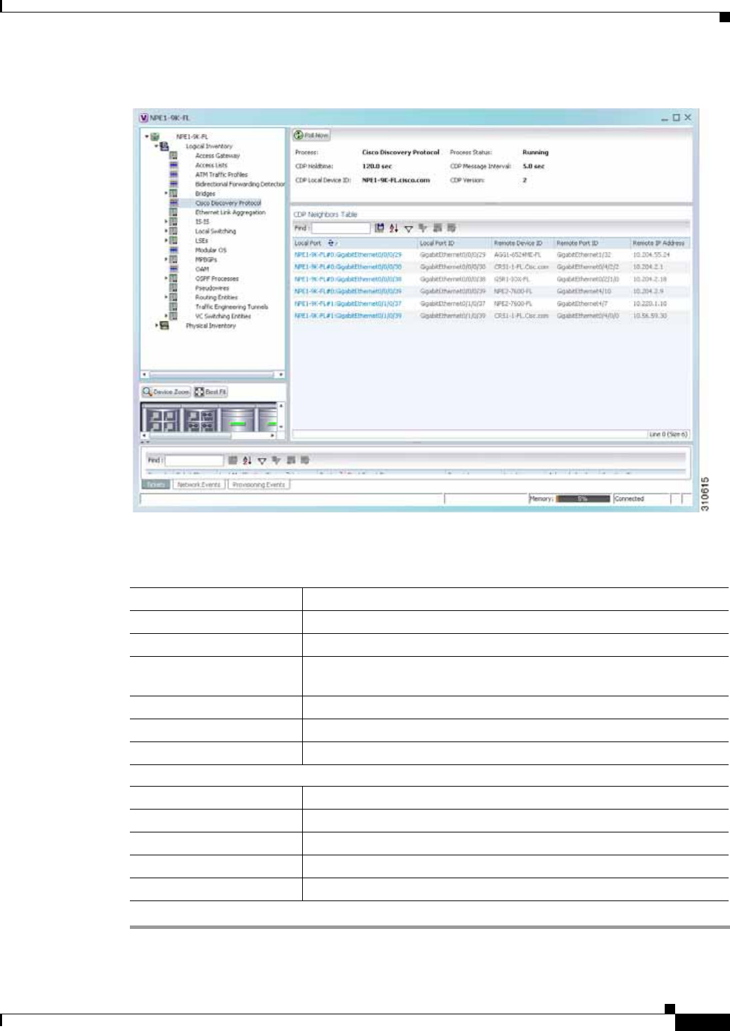
12-7
Cisco Prime Network 4.0 User Guide
OL-29343-01
Chapter 12 Monitoring Carrier Ethernet Services Viewing CDP Properties
Figure 12-1 CDP in Logical Inventory
Table 12-3 describes the CDP instance properties that are displayed.
Table 12-3 CDP Properties in Logical Inventory
Field Description
Process Process name; in this case, Cisco Discovery Protocol
Process Status Process status: Running or Disabled.
CDP Holdtime Specifies the amount of time a receiving device should hold the
information sent by a device before discarding it.
CDP Message Interval Interval between CDP advertisement transmissions.
CDP Local Device ID Local device identifier.
CDP Version CDP version: 1 or 2.
CDP Neighbors Table
Local Port Local port name.
Local Port ID Local port identifier.
Remote Device ID Remote device identifier.
Remote Port ID Remote port identifier.
Remote IP Address Remote IP address.

12-8
Cisco Prime Network 4.0 User Guide OL-29343-01
Chapter 12 Monitoring Carrier Ethernet Services
Viewing Link Layer Discovery Protocol Properties
In Physical Inventory
To view CDP on a Layer 2 port:
Step 1 In Prime Network Vision, double-click the device with the Layer 2 port with the CDP information you
want to view.
Step 2 In the inventory window, select the required port under Physical Inventory.
The CDP information is displayed in the Discovery Protocols area in the Prime Network Vision content
pane:
• Discovery Protocol Type—CDP
• Info—Up or Down
Viewing Link Layer Discovery Protocol Properties
Link Layer Discovery Protocol (LLDP) stores and maintains the local device information, including a
list of devices directly connected to the device.
In Logical Inventory
To view LLDP properties:
Step 1 In Prime Network Vision, double-click the device with the LLDP information you want to view.
Step 2 In the inventory window, choose Logical Inventory > Link Layer Discovery Protocol.
The LLDP properties are displayed in logical inventory as shown in Figure 12-2.
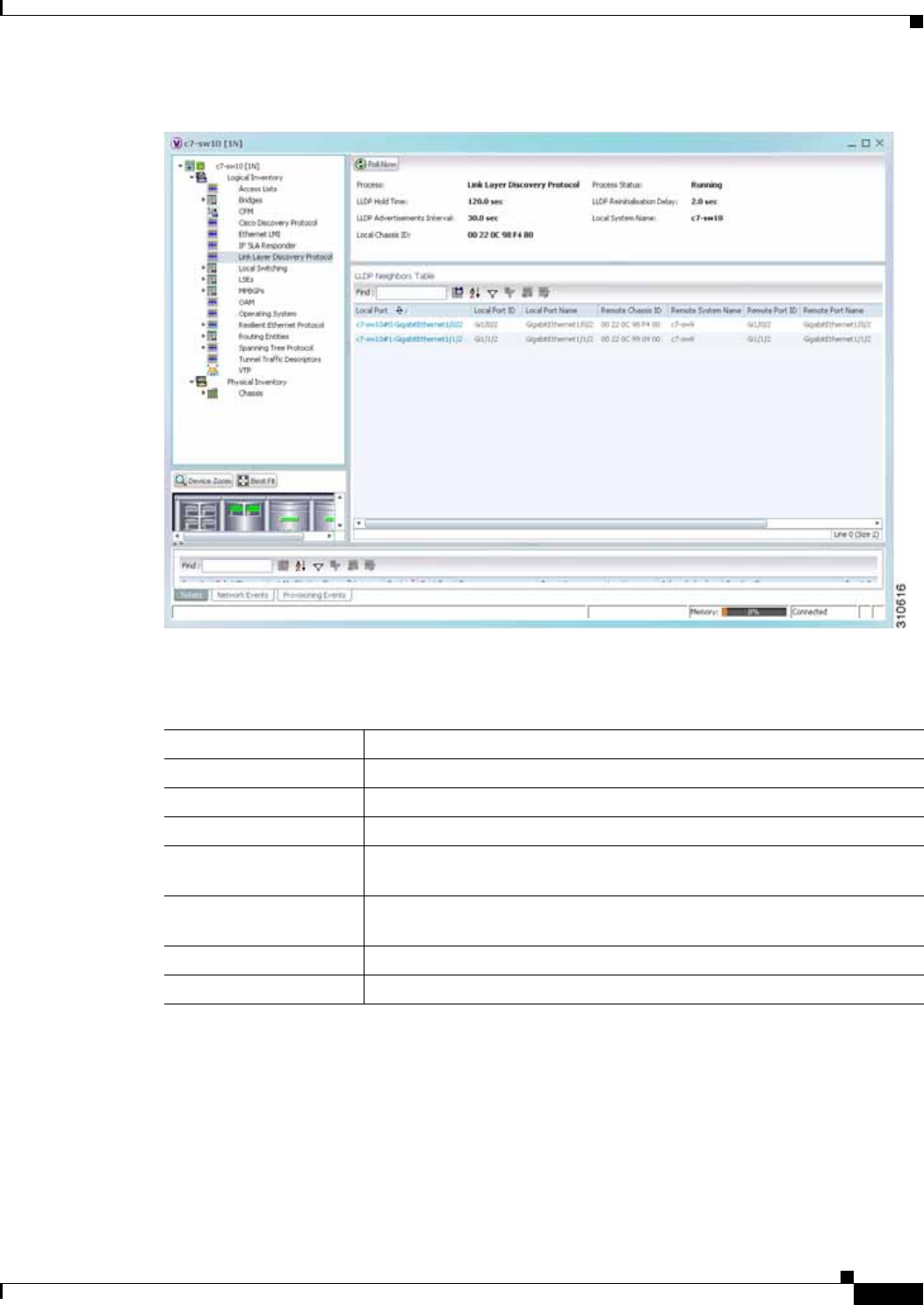
12-9
Cisco Prime Network 4.0 User Guide
OL-29343-01
Chapter 12 Monitoring Carrier Ethernet Services Viewing Link Layer Discovery Protocol Properties
Figure 12-2 LLDP in Logical Inventory
Table 12-4 describes the properties that are displayed for LLDP.
Table 12-4 Link Layer Discovery Protocol Properties
Field Description
Process Process; in this case, Link Layer Discovery Protocol
Process Status Process status: Running or Disabled.
LLDP Hold Time LLDP advertised hold time in seconds.
LLDP Reinitialization
Delay LLDP interface reinitialization delay in seconds
LLDP Advertisements
Interval LLDP advertisements interval in seconds.
Local System Name Local system name.
Local Chassis ID Local chassis identifier.

12-10
Cisco Prime Network 4.0 User Guide OL-29343-01
Chapter 12 Monitoring Carrier Ethernet Services
Viewing Spanning Tree Protocol Properties
In Physical Inventory
To view LLDP on a Layer 2 port:
Step 1 In Prime Network Vision, double-click the device with the Layer 2 port with LLDP information you want
to view.
Step 2 In the inventory window, select the required port under Physical Inventory.
The LLDP information is displayed in the Discovery Protocols area in the Prime Network Vision content
pane:
• Discovery Protocol Type—LLDP
• Info—Tx (Enabled or Disabled), Rx (Enabled or Disabled).
Viewing Spanning Tree Protocol Properties
Spanning Tree Protocol (STP) is a link management protocol that provides path redundancy while
preventing undesirable loops in the network.
To view Spanning Tree properties:
Step 1 In Prime Network Vision, double-click the element whose STP properties you want to view.
Step 2 In the inventory window, choose Logical Inventory > Spanning Tree Protocol.
Step 3 STP properties are displayed in logical inventory as shown in Figure 12-3.
LLDP Neighbors Table
Local Port Local port.
Local Port ID Local port identifier.
Local Port Name Local port name.
Remote System Name Remote system name.
Remote Chassis ID Remote chassis identifier.
Remote Port ID Remote port identifier.
Remote Port Name Remote port name.
Remote Management IP Remote management IP address.
Table 12-4 Link Layer Discovery Protocol Properties (continued)
Field Description
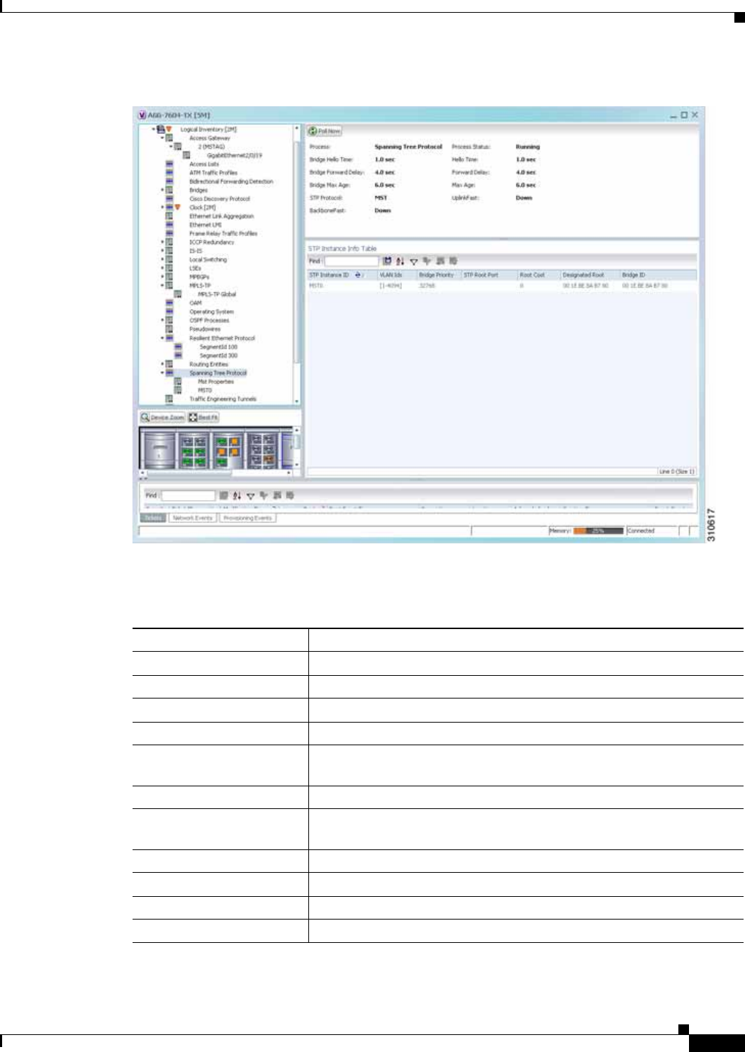
12-11
Cisco Prime Network 4.0 User Guide
OL-29343-01
Chapter 12 Monitoring Carrier Ethernet Services Viewing Spanning Tree Protocol Properties
Figure 12-3 STP in Logical Inventory
Table 12-5 describes the properties that are displayed for STP.
Table 12-5 STP Properties
Field Description
Process Process; in this case, Spanning Tree Protocol.
Process Status Process status: Running or Disabled.
Bridge Hello Time Hello message keepalive interval (in seconds) when the port is the root.
Hello Time Current hello time (in seconds).
Bridge Forward Delay When the port is the root and in listening or learning state, amount of
time to wait (in seconds) before proceeding to the forwarding state.
Forward Delay Current bridge forward delay (in seconds).
Bridge Max Age When the port is the root, maximum age of learned Spanning Tree
Protocol port information (in seconds).
Max Age Current maximum age (in seconds).
STP Protocol STP version: MST, RSTP, PVSTP, MSTP, or RPVST.
UplinkFast PVSTP Uplink Fast function status: Up or Down.
BackboneFast PVSTP BackboneFast function status: Up or Down.

12-12
Cisco Prime Network 4.0 User Guide OL-29343-01
Chapter 12 Monitoring Carrier Ethernet Services
Viewing Spanning Tree Protocol Properties
Step 4 To view the properties of an STP instance, do one of the following:
• Double-click the required instance.
• Click the required entry in logical inventory under the Spanning Tree Protocol branch.
Table 12-6 describes the information that is displayed in the STP Instance Information Properties
window.
STP Instance Info Table
STP Instance ID STP instance name.
VLAN IDs VLAN identifiers.
Bridge Priority Bridge priority.
STP Root Port Hyperlinked entry to the STP port in logical or physical inventory.
Root Cost Root cost value for this bridge.
Designated Root MAC address of the designated root.
Bridge ID Bridge identifier (MAC address).
Bridge Hello Time Hello message keepalive interval (in seconds) when the port is the root.
Hello Time Current hello time (in seconds).
Bridge Forward Delay When the port is the root and in the listening or learning state, amount
of time to wait (in seconds) before proceeding to the forwarding state.
Forward Delay Current bridge forward delay (in seconds).
Bridge Max Age When the port is the root, maximum age of learned Spanning Tree
Protocol port information (in seconds).
Max Age Current maximum age (in seconds).
Table 12-5 STP Properties (continued)
Field Description
Table 12-6 STP Instance Information Properties
Field Description
STP Instance ID STP instance identifier.
VLAN ID VLAN identifier.
Bridge Priority Bridge priority.
Bridge ID Bridge identifier (MAC address).
Root Cost Root cost value for this bridge.
Designated Root MAC address of the designated root.
Bridge Hello Time Hello message keepalive interval (in seconds) when the port is the root.
Hello Time Current hello time (in seconds).
Bridge Forward Delay When the port is the root and in listening or learning state, amount of
time to wait (in seconds) before proceeding to the forwarding state.
Forward Delay Current bridge forward delay (in seconds).
Bridge Max Age When the port is the root, the maximum age of learned Spanning Tree
Protocol port information (in seconds).

12-13
Cisco Prime Network 4.0 User Guide
OL-29343-01
Chapter 12 Monitoring Carrier Ethernet Services Viewing Spanning Tree Protocol Properties
Step 5 To view MSTP properties, choose the required MSTP entry in logical inventory under Spanning Tree
Protocol.
Table 12-7 describes the information that is displayed for MSTP.
Max Age Current maximum age (in seconds).
STP Protocol Specification Specific STP protocol type or variant used for this instance, such as
Rapid PvSTP.
Is Root Whether or not the port is the root: True or False.
Ports Info Table
STP Port Hyperlinked entry to the STP port in physical inventory.
Port State STP port state: Disabled, Blocking, Listening, Learning, or Forwarding,
Port Role Port role: Unknown, Backup, Alternative, Designated, Root, or
Boundary.
Port Priority Default 802.1p priority assigned to untagged packets arriving at the port.
Port Path Cost Port path cost, which represents the media speed for this port.
Point To Point Port Whether or not the port is linked to a point-to-point link: True or False.
Edge Port Whether or not the port is an edge port; that is, whether it is connected
to a nonbridging device: True or False.
MST Port Hello Time This field is displayed in the Ports Info Table only for MST.
In seconds, the interval between hello BPDUs sent by root switch
configuration messages. The range is 1 to 10 seconds.
Port Identifier STP port identifier.
Portfast Whether or not STP PortFast is enabled on the port: Up or Down.
Designated Port Identifier Designated STP port identifier.
Designated Bridge STP designated bridge.
BPDU Filter BPDU Filter status: Up or Down.
BPDU Guard BPDU Guard status: Up or Down.
Table 12-6 STP Instance Information Properties (continued)
Field Description

12-14
Cisco Prime Network 4.0 User Guide OL-29343-01
Chapter 12 Monitoring Carrier Ethernet Services
Viewing Resilient Ethernet Protocol Properties (REP)
The following topics describe how to view STP properties related to:
• VLAN domain views and overlays—See Viewing STP Information in VLAN Domain Views and
VLAN Overlays, page 12-66.
• VLAN service link properties—See Viewing STP Properties for VLAN Service Links, page 12-67.
Viewing Resilient Ethernet Protocol Properties (REP)
Cisco Resilient Ethernet Protocol (REP) technology is implemented on Cisco Carrier Ethernet switches
and intelligent service edge routers. REP is a segment protocol, and a REP segment is a chain of ports
connected to each other and configured with the same segment identifier. Each end of a segment
terminates on an edge switch. The port where the segment terminates is called the edge port.
Cisco Prime Network discovers and displays REP Segments (identified by a REP segment identifier that
is locally configured on the network element) along with Global REP configuration details.
You can also view the REP port roles (open, alternate, and failed) in the Cisco Prime Network Vision
map. The REP port role is displayed as a tool-tip between the REP enabled trunk ports in the Ethernet
links. Using the Cisco Prime Network Vision map, you can identify if the segment is open or closed.
The map displays the forwarding direction (REP port roles) along the Physical links within VLAN
overlays. It also displays the forwarding direction along the VLAN links among the switching elements
within the VLAN logical domain topology.
REP implementation supports the following faults:
• A REP Port Role change to Failed service event will be generated when a REP port role is change
from Alternate or Open to Failed.
• A REP Port Role change to OK clearing service event will be generated when a REP port role is
change from Failed to Alternate or Open.
Correlation to these service events to physical layer events (for example Link down or Port down) is also
performed.
You can view REP properties in logical inventory.
Step 1 In Prime Network Vision, double-click the device configured for REP.
Table 12-7 MSTP Properties in Logical Inventory
Field Description
MST Force Version Force version used: MST, PVSTP, RSTP, STP, or Unknown.
MST Cfg ID Rev Level Revision level used by the selected device and negotiated with other
devices.
MST Cfg ID Name MSTP instance name.
MST Max Instances Maximum number of MSTP instances.
MST Cfg ID Fmt Sel Configuration format used by this device and negotiated with other
devices.
MST External Root Cost External root cost of the MSTP instance.
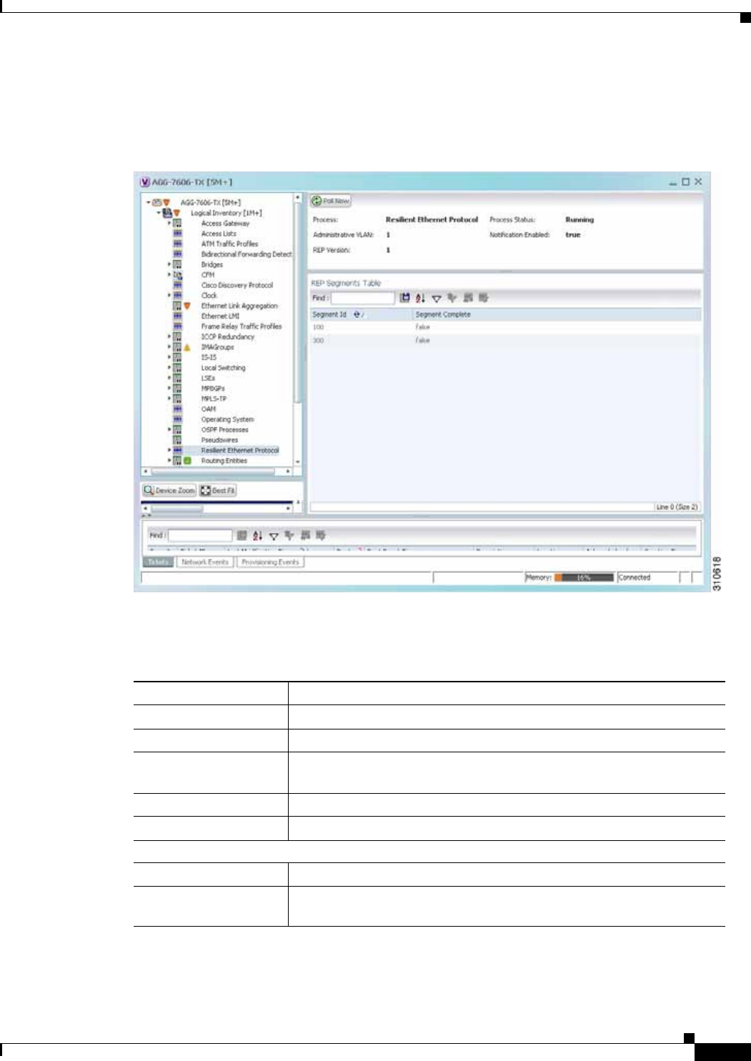
12-15
Cisco Prime Network 4.0 User Guide
OL-29343-01
Chapter 12 Monitoring Carrier Ethernet Services Viewing Resilient Ethernet Protocol Properties (REP)
Step 2 In the inventory window, choose Logical Inventory > Resilient Ethernet Protocol.
Figure 12-4 shows an example of REP in logical inventory.
Figure 12-4 REP in Logical Inventory
Table 12-8 describes the information that is displayed for REP.
Step 3 To view REP segment properties, double-click the required entry in the REP Segments table.
Figure 12-5 shows an example of REP segment properties in logical inventory.
Table 12-8 REP Properties
Field Description
Process Process name; in this case, Resilient Ethernet Protocol.
Process Status State of the REP process, such as Running or Down.
Administrative VLAN Administrative VLAN used by REP to transmit its hardware flooding
layer messages. Values range from 1 to 4094.
Notification Enabled Whether or not notification is enabled: True or False.
REP Version Version of REP being used.
REP Segments Table
Segment ID Segment identifier.
Segment Complete Whether the segment is complete; that is, that no port in the segment is
in a failed state: True or False.
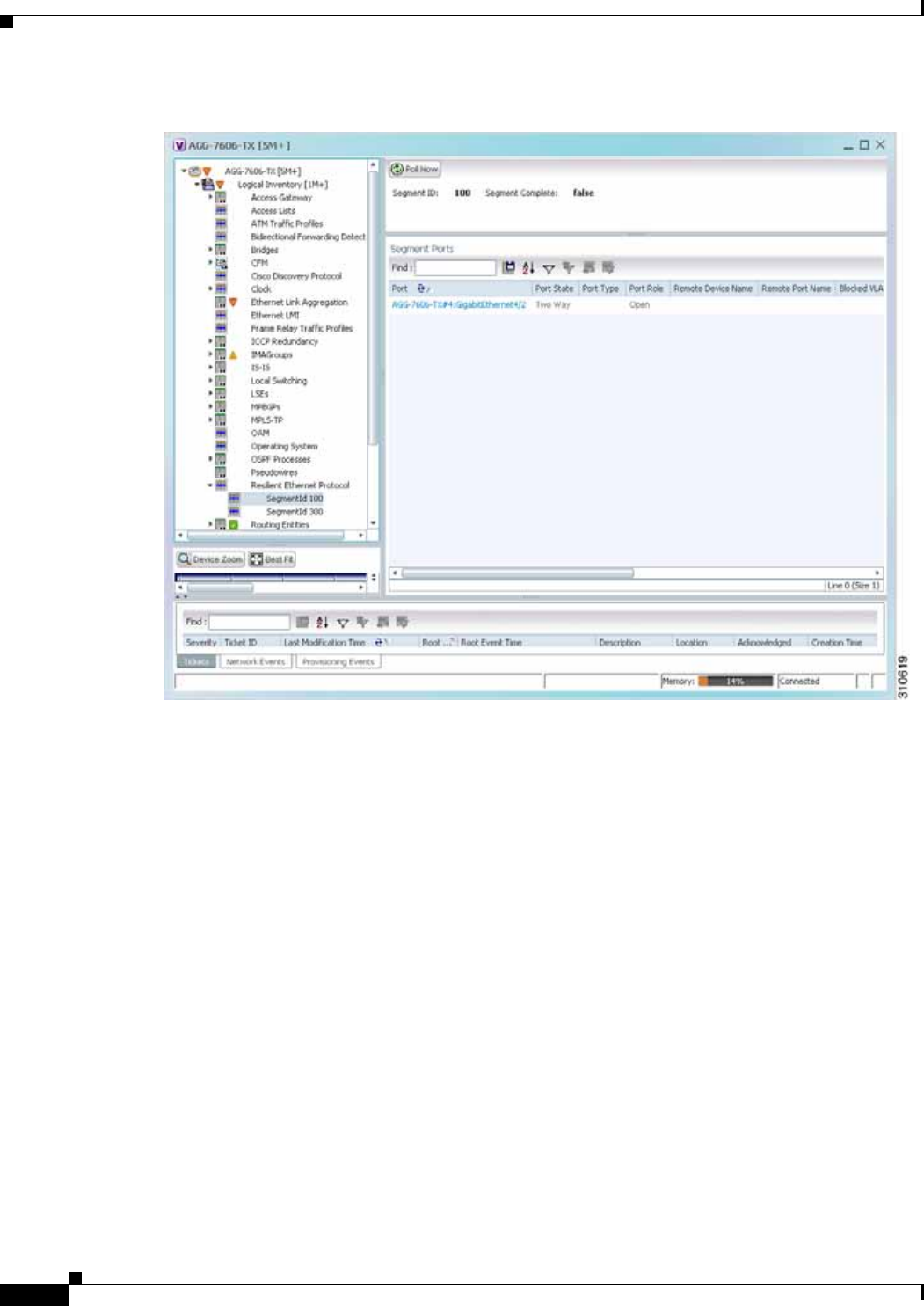

12-17
Cisco Prime Network 4.0 User Guide
OL-29343-01
Chapter 12 Monitoring Carrier Ethernet Services Viewing Resilient Ethernet Protocol Properties (REP)
The following topics describe how to view REP properties related to VLANs:
• VLAN domain views and overlays—See Viewing REP Information in VLAN Domain Views and
VLAN Overlays, page 12-63.
• VLAN service link properties—See Viewing REP Properties for VLAN Service Links, page 12-64.
Table 12-9 REP Segment Properties
Field Description
Segment ID Segment identifier.
Segment Complete Whether the segment is complete; that is, that no port in the segment is
in a failed state: True or False.
Segment Ports Table
Port Hyperlinked entry to the port in physical inventory.
Port State Current operational link state of the REP port: None, Init Down, No
Neighbor, One Way, Two Way, Flapping, Wait, or Unknown.
Port Type Port type: Primary Edge, Secondary Edge, or Intermediate.
Port Role Role or state of the REP port depending on its link status and whether it
is forwarding or blocking traffic: Failed, Alternate, or Open.
Remote Device Name Name of the neighbor device that this port is connected to on this
segment. This value can be null.
Remote Port Name Name of the neighbor port on the neighbor bridge that this port is
connected to on this segment. This value can be null.
Blocked VLANs VLANs that are blocked on this port.
Configured Load
Balancing Blocked
VLANs
List of VLANs configured to be blocked at this port for REP VLAN load
balancing.
Preemptive Timer Amount of time, in seconds, that REP waits before triggering
preemption after the segment is complete. The entry can range from 0 to
300, or be Disabled.
The value Disabled indicates that no time delay is configured, and that
the preemption occurs manually.
This property applies only to REP primary edge ports.
LSL Ageout Timer Using the Link Status Layer (LSL) age-out timer, the amount of time, in
milliseconds, that the REP interface remains up without receiving a
hello from a neighbor.
Remote Device MAC MAC address of the neighbor bridge that this port is connected to on this
segment. This value can be null.
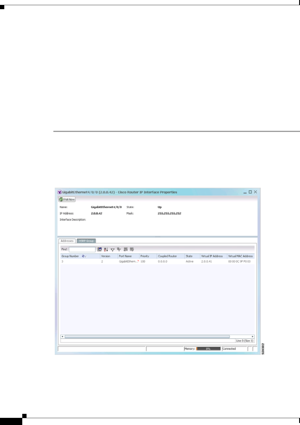
12-18
Cisco Prime Network 4.0 User Guide OL-29343-01
Chapter 12 Monitoring Carrier Ethernet Services
Viewing HSRP Properties
Viewing HSRP Properties
Hot Standby Router Protocol (HSRP) is a protocol that provides backup to a router in case of failure.
Using HSRP, several routers are connected to the same Ethernet network segment and work together to
present the appearance of a single virtual router. The routers share the same IP and MAC addresses;
therefore in the event of failure of one router, the hosts on the LAN will be able to continue forwarding
packets to a consistent IP and MAC address.
HSRP groups are configured on IP interfaces. An IP interface is modeled by the VNE through the
IPInterface DC. The IPInterface DC maintains the HSRP related information by the use of HSRP group
entries. Ethernet DCs, which are used to model Ethernet ports, maintain MAC addresses of the HSRP
groups.
To view HSRP properties:
Step 1 Double-click the required element in Prime Network Vision.
Step 2 In logical inventory, choose Logical Inventory > Routing Entities > Routing Entity.
Step 3 In the IP Interfaces tab, double-click the required interface to view the IP interface properties. If HSRP
is configured on the IP interface, the HSRP Group tab is displayed as shown in Figure 12-6.
Figure 12-6 HSRP Group Information
Table 12-10 describes the information in the HSRP Group tab.

12-19
Cisco Prime Network 4.0 User Guide
OL-29343-01
Chapter 12 Monitoring Carrier Ethernet Services Viewing Access Gateway Properties
Viewing Access Gateway Properties
In an access network, an access gateway configuration ensures loop-free connectivity in the event of
various failures by sending statically configured bridge protocol data units (BPDUs) toward the access
network. Using statically configured BPDUs enables the gateway device to act appropriately when
notified of the following topology changes:
• Failure of a link in the access network.
• Failure of a link between the access network and the gateway device.
• Failure of an access device.
• Failure of a gateway device.
To view access gateway properties:
Step 1 Double-click the element configured for access gateway.
Step 2 In the inventory window, choose Logical Inventory > Access Gateway > access-gateway. The group
name is appended by either MSTAG or REPAG, indicating the group type Multiple Spanning Tree
Access Gateway or Resilient Ethernet Protocol Access Gateway.
Figure 12-7 shows an example of an access gateway entry in logical inventory.
Table 12-10 HSRP Group Properties
Field Description
Group Number Number of the HSRP group associated with the interface.
Version Version of the HSRP group.
Port Name Port on which the HSRP is configured.
Priority Value that determines the role each HSRP router plays.
Values are 1 through 254, with higher numbers having priority over
lower numbers.
Coupled Router The partnet router.
State State of the HSRP group: Active or Standby.
Virtual IP Address Virtual IP address assigned to the active router.
Virtual MAC Address Virtual MAC address assigned to the active router.
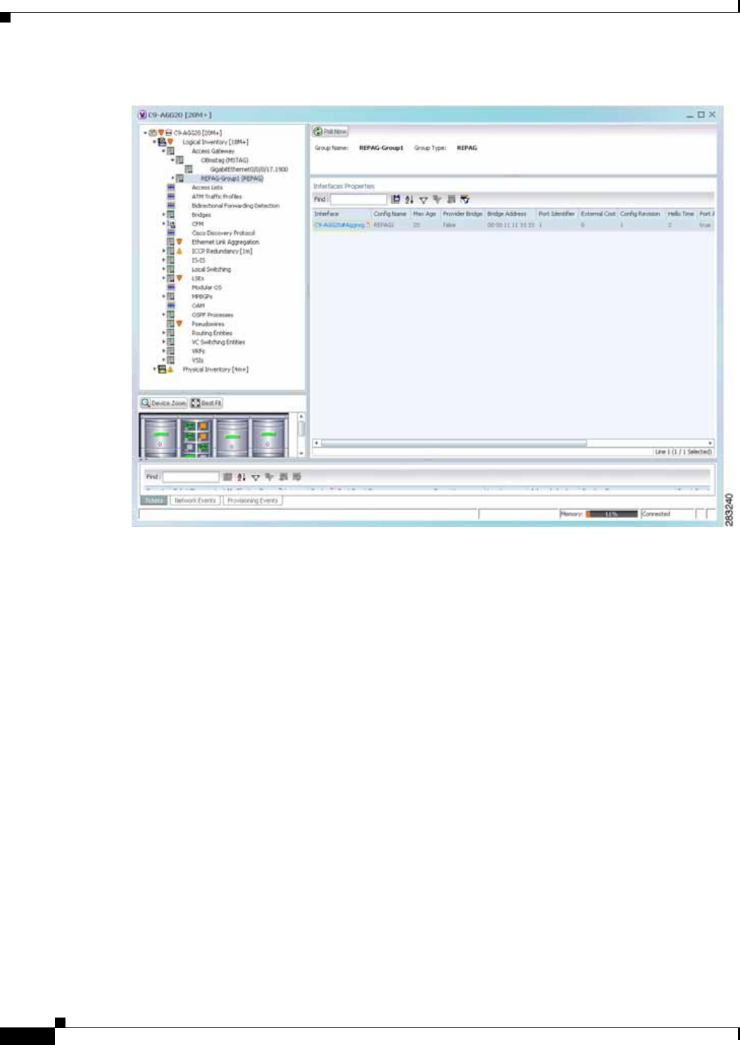
12-20
Cisco Prime Network 4.0 User Guide OL-29343-01
Chapter 12 Monitoring Carrier Ethernet Services
Viewing Access Gateway Properties
Figure 12-7 Access Gateway in Logical Inventory

12-21
Cisco Prime Network 4.0 User Guide
OL-29343-01
Chapter 12 Monitoring Carrier Ethernet Services Viewing Access Gateway Properties
Table 12-11 describes the information that is displayed for an access gateway.
Step 3 Choose an access gateway instance to view instance properties.
Figure 12-8 shows an example of the information displayed for an access gateway instance.
Table 12-11 Access Gateway Properties in Logical Inventory
Field Description
Group Name Access gateway group name.
Group Type Group type: MSTAG or REPAG.
Interface Properties
Interface Hyperlink to the interface in physical inventory on which access
gateway is configured.
Config Name Name of the MSTP region.
The default value is the MAC address of the switch, formatted as a
text string using the hexadecimal representation specified in IEEE
Standard 802.
Max Age In seconds, the maximum age for the bridge.
Values range from 6 to 40 seconds.
Provider Bridge Whether the current instance of the protocol is in 802.1ad mode:
True or False.
Bridge Address Bridge identifier for the interface.
Port Identifier Port identifier for the interface.
External Cost External path cost on the current port.
Values range from 1 to 200000000.
Config Revision Number of the configuration revision.
Hello Time Current hello time (in seconds)
Port Active Whether or not the port is active: True or False.
BPDUs Sent Number of BPDUs sent.
Reversion Control Enabled Whether reversion control is enabled: True or False.
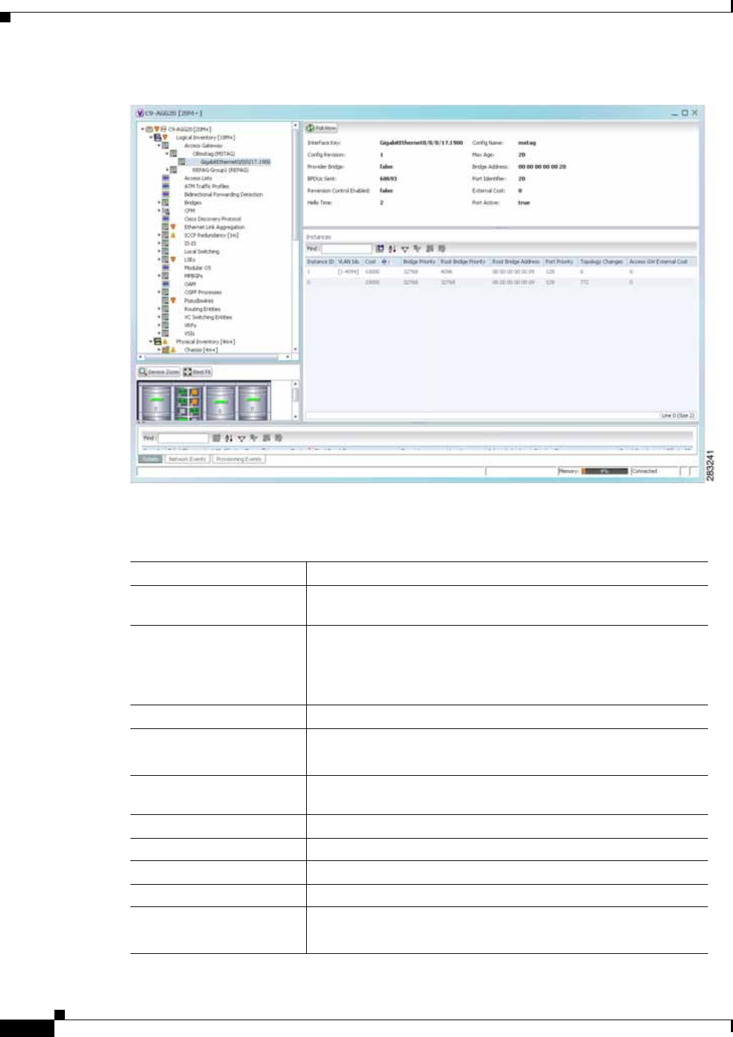
12-22
Cisco Prime Network 4.0 User Guide OL-29343-01
Chapter 12 Monitoring Carrier Ethernet Services
Viewing Access Gateway Properties
Figure 12-8 Access Gateway Instance in Logical Inventory
Table 12-12 describes the information that is displayed for an access gateway instance.
Table 12-12 Access Gateway Instance Properties
Field Description
Interface Key Hyperlink to the interface in physical inventory on which access
gateway is configured.
Config Name Name of the MSTP region.
The default value is the MAC address of the switch, formatted as a
text string using the hexadecimal representation specified in IEEE
Standard 802.
Config Revision Number of the configuration revision.
Max Age In seconds, the maximum age for the bridge.
Values range from 6 to 40 seconds.
Provider Bridge Whether the current instance of the protocol is in 802.1ad mode:
True or False.
Bridge Address Bridge identifier for the current switch.
BPDUs Sent Number of BPDUs sent.
Port Identifier Port identifier for the interface.
Reversion Control Enabled Whether reversion control is enabled: True or False.
External Cost External path cost on the current port.
Values range from 1 to 200000000.

12-23
Cisco Prime Network 4.0 User Guide
OL-29343-01
Chapter 12 Monitoring Carrier Ethernet Services Working with Ethernet Link Aggregation Groups
Working with Ethernet Link Aggregation Groups
Ethernet link aggregation groups (LAGs) provide the ability to treat multiple switch ports as one switch
port. The port groups act as a single logical port for high-bandwidth connections between two network
elements. A single link aggregation group balances the traffic load across the links in the channel.
LAG links are discovered automatically for devices that support LAG technology and use VNEs that
model Link Aggregation Control Protocol (LACP) attributes.
You can create static links between Ethernet LAGs by choosing a LAG and the desired port channel for
the A or Z side as described in Adding Static Links, page 6-15.
If a physical link within the link aggregation group fails, the following actions occur:
• Traffic that was previously carried over the failed link is moved to the remaining links.
Most protocols operate over single ports or aggregated switch ports and do not recognize the
physical ports within the port group.
• An aggregation service alarm is generated.
The aggregation service alarm indicates the percentage of links within the aggregation that have
failed. For example, if an Ethernet link aggregation group contains four Ethernet links and one fails,
the aggregation service alarm indicates that 25% of the links are down.
Viewing Ethernet LAG Properties
Note Cisco CRS devices must be configured to receive SNMP traps in order to view Ethernet LAG properties.
For more information on required SNMP settings, see the Cisco Prime Network4.0 Administrator Guide.
Hello Time Current hello time (in seconds)
Port Active Whether or not the port is active: True or False.
Instances Table
Instance ID Access gateway instance identifier.
VLAN IDs VLAN identifiers.
Cost Path cost for this instance.
Bridge Priority Priority associated with current bridge.
Root Bridge Priority Priority associated with the root bridge.
Root Bridge Address Address of the root bridge.
Port Priority Priority of the interface for this instance.
Topology Changes Number of times the topology has changed for this instance.
Access GW External Cost External root cost of this instance.
Table 12-12 Access Gateway Instance Properties (continued)
Field Description
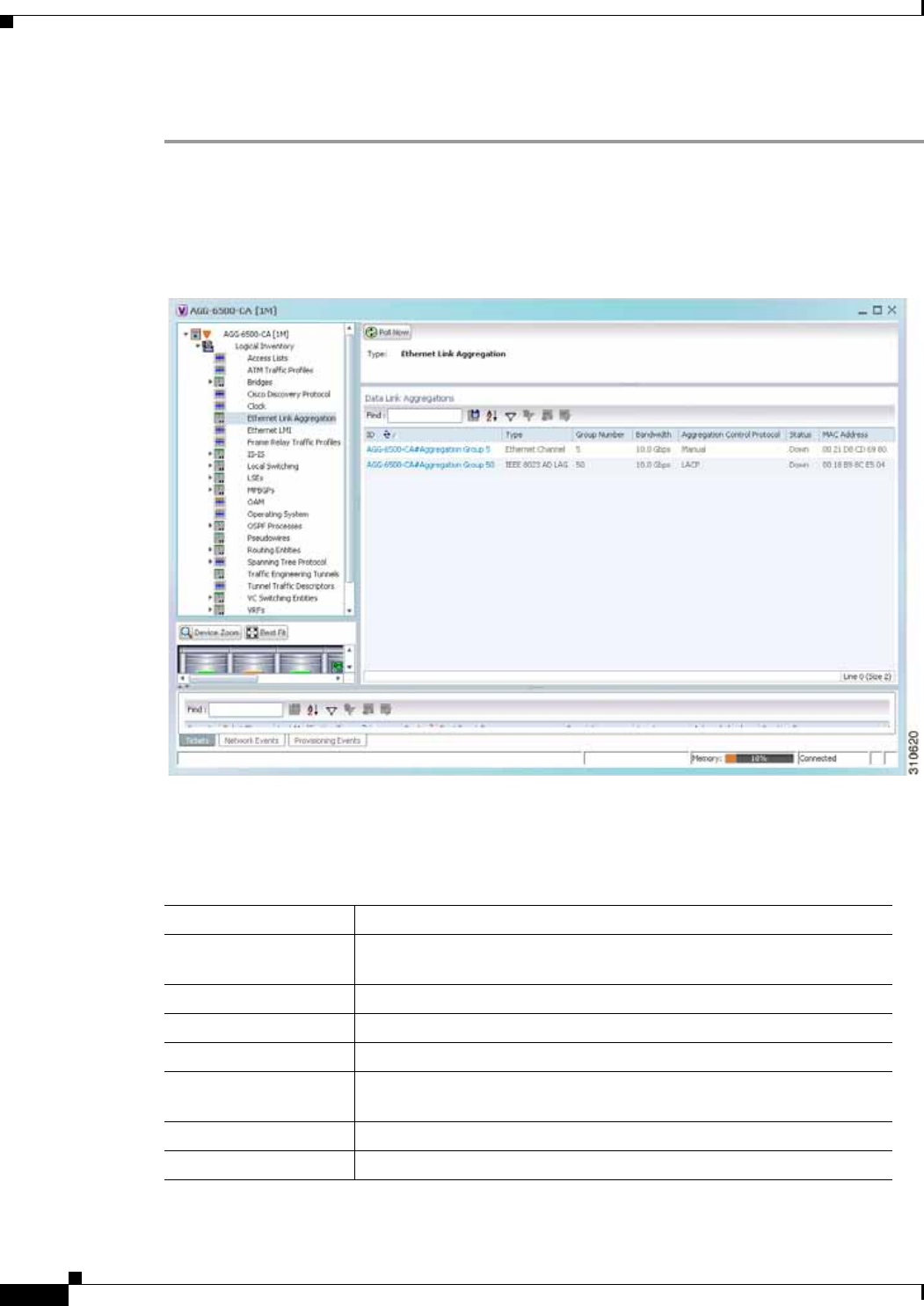
12-24
Cisco Prime Network 4.0 User Guide OL-29343-01
Chapter 12 Monitoring Carrier Ethernet Services
Working with Ethernet Link Aggregation Groups
To view properties for Ethernet link aggregation groups:
Step 1 In Prime Network Vision, double-click the device with the link aggregation group you want to view.
Step 2 In the inventory window, choose Logical Inventory > Ethernet Link Aggregation.
The link aggregation properties are displayed as shown in Figure 12-9.
Figure 12-9 Ethernet Link Aggregation in Logical Inventory
Table 12-13 describes the aggregation group properties that are displayed in the Data Link Aggregations
table.
Table 12-13 Data Link Aggregations Table
Field Description
ID Aggregation identifier. Double-click the entry to view the properties for
that aggregation.
Type Aggregation group type: Ethernet Channel or IEEE 8023 AD LAG.
Group Number Aggregation group number.
Bandwidth Aggregation bandwidth.
Aggregation Control
Protocol Aggregation control protocol: Manual, Link Aggregation Control
Protocol (LACP), or Port Aggregation Protocol (PagP).
Status Aggregation status: Up or Down.
MAC Address Aggregation MAC address.

12-25
Cisco Prime Network 4.0 User Guide
OL-29343-01
Chapter 12 Monitoring Carrier Ethernet Services Working with Ethernet Link Aggregation Groups
Step 3 To view properties for a specific aggregation, double-click the group identifier.
The information that is displayed depends on the type of aggregation:
• For Ethernet Channel aggregations, see Table 12-14.
• For IEEE 802.3 AD aggregations, see Table 12-15.
Table 12-14 LAG Ethernet Channel Properties
Field Description
Group Number Aggregation group number.
Bandwidth Aggregation bandwidth in b/s.
Control Protocol Aggregation control protocol: Manual, Link Aggregation Control Protocol (LACP), or Port
Aggregation Protocol (PagP).
MAC Address Aggregation MAC address.
Administrative State Aggregation administrative status: Up or Down.
Operational State Aggregation operational status: Up or Down.
Adjacent Adjacent group, hyperlinked to the group in logical inventory.
mLACP Properties mLACP properties are displayed if the aggregation group is associated with an ICCP redundancy
group.
ICCP Redundancy
Group ICCP redundancy group associated with this aggregation group, hyperlinked to the relevant entry
in logical inventory.
mLACP Role Role of the LAG in the redundancy group: Active or Standby.
mLACP Operational
System MAC MAC address used in a dual-homed environment that is selected by ICCP from one of the
configured system MAC addresses for one of the points of attachment (PoAs).
mLACP Operational
System Priority Priority used in a dual-homed environment that is selected by ICCP from the configured system
priority on one of the PoAs.
mLACP Failover
Option Configured mLACP failover mode: Revertive or Nonrevertive.
mLACP Max Bundle Maximum number of links allowed per bundle.
Aggregated Ports Table
ID Aggregated port identifier, hyperlinked to the interface in physical inventory.
Type Aggregation type, such as Layer 2 VLAN.
Mode VLAN mode, such as Trunk.
Native VLAN ID VLAN identifier (VID) associated with this VLAN. The range of VLANs is 1 to 4067.
VLAN Encapsulation
Type Type of encapsulation configured on the VLAN, such as IEEE 802.1Q.
Allowed VLANs List of VLANs allowed on this interface.
VLAN Encapsulation
Admin Type VLAN administration encapsulation type, such as IEEE 802.1Q.
Subinterfaces Table
Address IP address of the subinterface.
Mask Subnet mask applied to the IP address.
VLAN Type Type of VLAN, such as Bridge or IEEE 802.1Q.

12-26
Cisco Prime Network 4.0 User Guide OL-29343-01
Chapter 12 Monitoring Carrier Ethernet Services
Working with Ethernet Link Aggregation Groups
Operational State Operational state of the subinterface: Up or Down.
VLAN ID VLAN identifier.
Inner VLAN CE-VLAN identifier.
IP Interface IP interface configured as part of the subinterface, hyperlinked to the routing entity or VRF in
logical inventory.
VRF Name VRF associated with the subinterface.
Is MPLS Whether the subinterface is enabled for MPLS: True or False.
This column is displayed when at least one interface is MPLS-enabled.
Tunnel Edge Whether this is a tunnel edge: True or False.
VC Virtual circuit identifier, hyperlinked to the VC Table when the subinterface is configured for ATM
VC.
Binding Hyperlinked entry to the specific bridge in logical inventory.
EFPs Table
EFP ID EFP identifier.
Operational State EFP operational state: Up or Down.
VLAN VLAN associated with this EFP.
Inner VLAN CE-VLAN identifier.
Translated VLAN Translated, or mapped, VLAN identifier.
Translated Inner VLAN Translated, or mapped, inner VLAN identifier.
Binding Hyperlinked entry to the specific bridge in logical inventory.
Description Description for the EFP.
Table 12-14 LAG Ethernet Channel Properties (continued)
Field Description

12-27
Cisco Prime Network 4.0 User Guide
OL-29343-01
Chapter 12 Monitoring Carrier Ethernet Services Working with Ethernet Link Aggregation Groups
Table 12-15 LAG IEEE 802.3 AD Properties
Field Description
Group Number Aggregation group number.
Bandwidth Aggregation bandwidth.
Control Protocol Aggregation control protocol: Manual, Link Aggregation Control
Protocol (LACP), or Port Aggregation Protocol (PagP).
MAC Address Aggregation MAC address.
Administrative State Aggregation administrative status: Up or Down.
Operational State Aggregation operational status: Up or Down.
Dot3ad Agg Partner System Priority Priority of the partner system.
Dot3ad Agg MAC Address Aggregation MAC address.
Dot3ad Agg Actor Admin Key Actor administrative key.
Dot3ad Agg Actor System Priority Actor system priority.
Dot3ad Agg Partner Oper Key Partner operational key.
Dot3ad Agg Actor Oper Key Actor operational key.
Dot3ad Agg Collector Max Delay Maximum delay (in microseconds) for either delivering or discarding a
received frame by the frame collector.
Dot3ad Agg Actor System ID Actor system identifier, in the form of a MAC address.
Dot3ad Agg Partner System ID Partner system identifier, in the form of a MAC address.
mLACP Properties mLACP properties are displayed if the aggregation group is associated
with an ICCP redundancy group.
ICCP Redundancy Group ICCP redundancy group associated with this aggregation group,
hyperlinked to the relevant entry in logical inventory.
mLACP Role Role of the LAG in the redundancy group: Active or Standby.
mLACP Operational System MAC MAC address used in a dual-homed environment that is selected by
ICCP from one of the configured system MAC addresses for one of the
points of attachment (PoAs).
mLACP Operational System Priority Priority used in a dual-homed environment that is selected by ICCP from
the configured system priority on one of the PoAs.
mLACP Failover Option Configured mLACP failover mode: Revertive or Nonrevertive.
mLACP Max Bundle Maximum number of links allowed per bundle.
Aggregated Ports Table
ID Port identifier, hyperlinked to the interface in physical inventory.
Type Type of VLAN, such as Layer 2 VLAN.
Discovery Protocols Discovery protocols used on this port.

12-28
Cisco Prime Network 4.0 User Guide OL-29343-01
Chapter 12 Monitoring Carrier Ethernet Services
Working with Ethernet Link Aggregation Groups
Subinterfaces Table
Address IP address of the subinterface.
Mask Subnet mask applied to the IP address.
VLAN Type Type of VLAN, such as Bridge or IEEE 802.1Q.
Operational State Operational state of the subinterface: Up or Down.
VLAN ID VLAN identifier.
Inner VLAN CE-VLAN identifier.
IP Interface IP interface configured as part of the subinterface, hyperlinked to the
routing entity or VRF in logical inventory.
VRF Name VRF associated with the subinterface.
VC Virtual circuit identifier, hyperlinked to the VC Table when the
subinterface is configured for ATM VC.
Binding Hyperlinked entry to the specific bridge in logical inventory.
EFPs Table
EFP ID EFP identifier.
Operational State EFP operational state: Up or Down.
VLAN VLAN associated with this EFP.
Inner VLAN CE-VLAN identifier.
Translated VLAN Translated, or mapped, VLAN identifier.
Translated Inner VLAN Translated, or mapped, inner VLAN identifier.
Binding Hyperlinked entry to the specific bridge in logical inventory.
Description Description for the EFP.
LACP Port Entries
Aggregated Port Port on which the aggregation is configured, hyperlinked to the entry in
physical inventory.
Dot3ad Agg Port Partner Admin Port Priority Administrative port priority for the partner.
Dot3ad Agg Port Partner Admin Key Administrative key for the partner port.
Dot3ad Agg Port Partner Oper Port Priority Priority assigned to the aggregation port by the partner.
Dot3ad Agg Port Actor Oper State Local operational state for the port.
Dot3ad Agg Port Actor Admin State Local administrative state as transmitted by the local system in LACP
data units (LACPDUs).
Dot3ad Agg Port Selected Agg ID Selected identifier for the aggregation port.
Dot3ad Agg Port Partner Oper Key Operational key for the partner port.
Dot3ad Agg Port Partner Admin State Partner administrative state.
Dot3ad Agg Port Actor Port Priority Priority assigned to the local aggregation port.
Dot3ad Agg Port Partner Oper State Partner administrative state as transmitted by the partner in the most
recently transmitted LAPCDU.
Dot3ad Agg Port Attached Agg ID Identifier of the aggregator that the port is attached to.
Table 12-15 LAG IEEE 802.3 AD Properties (continued)
Field Description
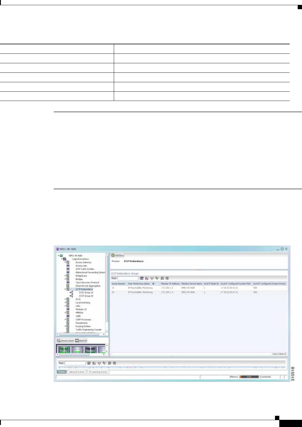
12-29
Cisco Prime Network 4.0 User Guide
OL-29343-01
Chapter 12 Monitoring Carrier Ethernet Services Viewing mLACP Properties
Viewing mLACP Properties
Prime Network Vision supports the discovery of Multichassis LACP (mLACP) configurations on devices
configured for them, and displays mLACP configuration information, such as redundancy groups and
properties, in inventory.
To view mLACP properties:
Step 1 In Prime Network Vision, double-click the element configured for mLACP.
Step 2 In the inventory window, choose Logical Inventory > ICCP Redundancy.
In response, Prime Network Vision lists the Inter-Chassis Communication Protocol (ICCP) redundancy
groups configured on the device as shown in Figure 12-10.
Figure 12-10 ICCP Redundancy in Logical Inventory
Dot3ad Agg Port Actor Admin Key Administrative key for the local port.
Dot3ad Agg Port Actor Port Number assigned to the local aggregation port.
Dot3ad Agg Port Partner Oper Port Number assigned to the aggregation port by the partner.
Dot3ad Agg Port Actor Oper Key Operational for the local port.
Dot3ad Agg Port Partner Admin Port Administrative value of the port for the partner.
Table 12-15 LAG IEEE 802.3 AD Properties (continued)
Field Description

12-30
Cisco Prime Network 4.0 User Guide OL-29343-01
Chapter 12 Monitoring Carrier Ethernet Services
Viewing mLACP Properties
Table 12-16 describes the information displayed in the ICCP Redundancy Groups table.
Step 3 To view additional information about an ICCP redundancy group, do either of the following:
• In the logical inventory window navigation pane, choose Logical Inventory ICCP
Redundancy > ICCP-group.
• In the logical inventory content pane, right-click the required group in the ICCP Redundancy Groups
table and choose Properties.
The ICCP Redundancy Group Properties window is displayed with the Backbone Interfaces and Data
Link Aggregations tabs as shown in Figure 12-11.
Figure 12-11 ICCP Redundancy Group Properties Window
Table 12-16 ICCP Redundancy Groups in Logical Inventory
Field Description
Group Number ICCP group identifier.
Peer Monitoring Option Method used to monitor the peer: BFD or IP Reachability
Monitoring.
Member IP Address IP address of the neighbor PoA device.
Member Device Name Name of the neighbor PoA device.
mLACP Node ID Identifier used by this member of the mLACP redundancy group.
mLACP Configured System
MAC System MAC address of the redundancy group advertised to other
members of the mLACP redundancy group and used for arbitration.
mLACP Configured System
Priority System priority advertised to other mLACP members of the
redundancy group.

12-31
Cisco Prime Network 4.0 User Guide
OL-29343-01
Chapter 12 Monitoring Carrier Ethernet Services Viewing mLACP Properties
Table 12-17 describes the information available in the ICCP Redundancy Group Properties window.
Step 4 To view additional mLACP properties, double-click the entry for the required link aggregation group in
the Data Link Aggregations tab.
mLACP information is displayed in the Link Aggregation Group Properties window, as described in the
following tables:
• Table 12-14—LAG Ethernet Channel Properties
• Table 12-15—LAG IEEE 802.3 AD Properties
Table 12-17 ICCP Redundancy Group Properties Window
Field Description
Group Number ICCP group identifier.
Peer Monitoring Option Method used to monitor the peer: BFD or IP Reachability
Monitoring.
Member IP Address IP address of the neighbor PoA device.
Member device name Name of the neighbor PoA device.
mLACP Node ID Identifier used by this member of the mLACP redundancy group.
mLACP Configured System
MAC System MAC address of the redundancy group advertised to other
members of the mLACP redundancy group and used for arbitration.
mLACP Configured System
Priority System priority advertised to other mLACP members of the
redundancy group.
Backbone Interfaces Tab
ID Backbone interface defined for the redundancy group, hyperlinked
to the relevant entry in logical inventory.
Status Status of the backbone interface: Up, Down, or Unknown.
Data Link Aggregations Tab
ID Link aggregation group associated with the redundancy group,
hyperlinked to the relevant entry in logical inventory.
Type Aggregation group type: Ethernet Channel or IEEE 8023 AD LAG.
Group Number Aggregation group number.
Bandwidth Aggregation bandwidth.
Aggregation Control
Protocol Aggregation control protocol: Manual, LACP, or PAgP.
Status Aggregation status: Up or Down.
MAC Address Aggregation MAC address.
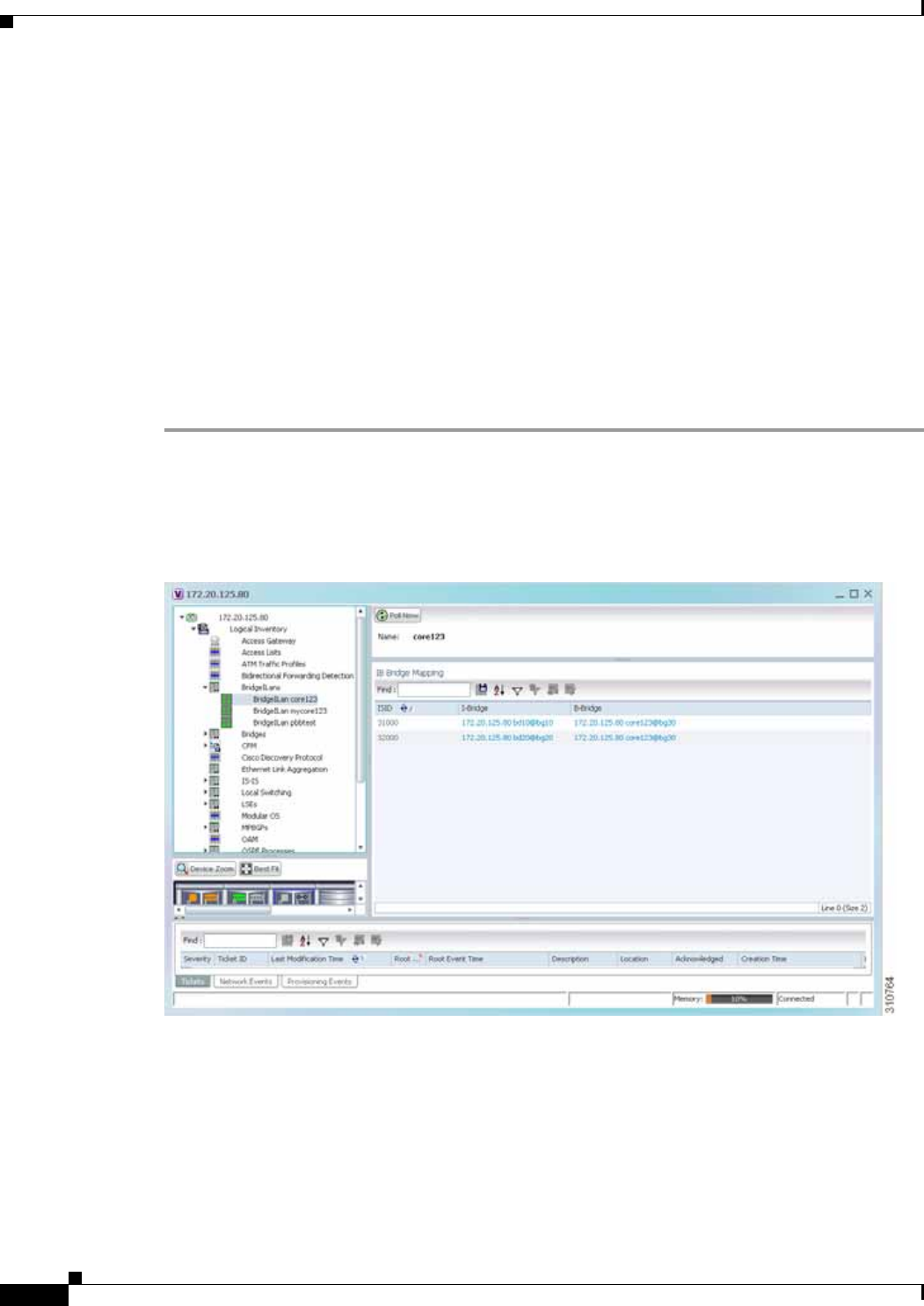
12-32
Cisco Prime Network 4.0 User Guide OL-29343-01
Chapter 12 Monitoring Carrier Ethernet Services
Viewing Provider Backbone Bridge Properties
Viewing Provider Backbone Bridge Properties
Provider backbone bridges (PBBs), specified by IEEE 802.1ah-2008, provide a way to increase the
number of service provider supported Layer 2 service instances beyond the number supported by QinQ
and VPLS. PBB adds a backbone VLAN tag and backbone destination and source MAC addresses to
encapsulate customer Ethernet frames and create a MAC tunnel across core switches.
Prime Network supports PBB inventory discovery and modeling for the following devices:
• Cisco 7600-series devices running Cisco IOS version 12.2(33)SRE1
• Cisco ASR 9000-series devices running Cisco IOS XR version 3.9.1
Prime Network models the IB type of Backbone edge bridges which includes both I-type and B-type
components.
To view PBB properties:
Step 1 In Prime Network Vision, double-click the element configured for PBB.
Step 2 In the inventory window, choose Logical Inventory > BridgeILans > PBB-bridge.
Figure 12-12 shows an example of PBB properties in logical inventory.
Figure 12-12 PBB Properties in Logical Inventory

12-33
Cisco Prime Network 4.0 User Guide
OL-29343-01
Chapter 12 Monitoring Carrier Ethernet Services Viewing EFP Properties
Table 12-18 describes the information displayed for PBB.
Viewing EFP Properties
Prime Network Vision provides information about EFPs in a number of ways. For example:
• EFP names displayed in Prime Network Vision maps add EFP and the managed element name to the
interface name, such as GigabitEthernet4/0/1 EFP: 123@c4-npe5-67.
• If you select an EFP in the navigation pane in Prime Network Vision and then click Show List View,
an Ethernet Flow Points table lists the network element, port, and network VLAN associated with
the EFP.
To view additional EFP properties:
Step 1 In the Prime Network Vision map view, select the required EFP in the navigation pane or in the map pane
and then do either of the following:
• Right-click the EFP and choose Properties.
• Choose Node > Properties.
Table 12-18 PBB Properties in Logical Inventory
Field Description
Name Identifier of the bridge as follows:
• For Cisco 7600 devices, the identifier of the MAC tunnel
created.
• For Cisco ASR 9000-series devices, the identifier is a
combination of the bridge group and the bridge domain on the
B-Bridge component.
IB Bridge Mapping Table
ISID 24-bit entry representing the Backbone service instance.
I-Bridge XID of the I-Bridge component, hyperlinked to the relevant bridge
in logical inventory.
B-Bridge XID of the B-Bridge component, hyperlinked to the relevant bridge
in logical inventory.
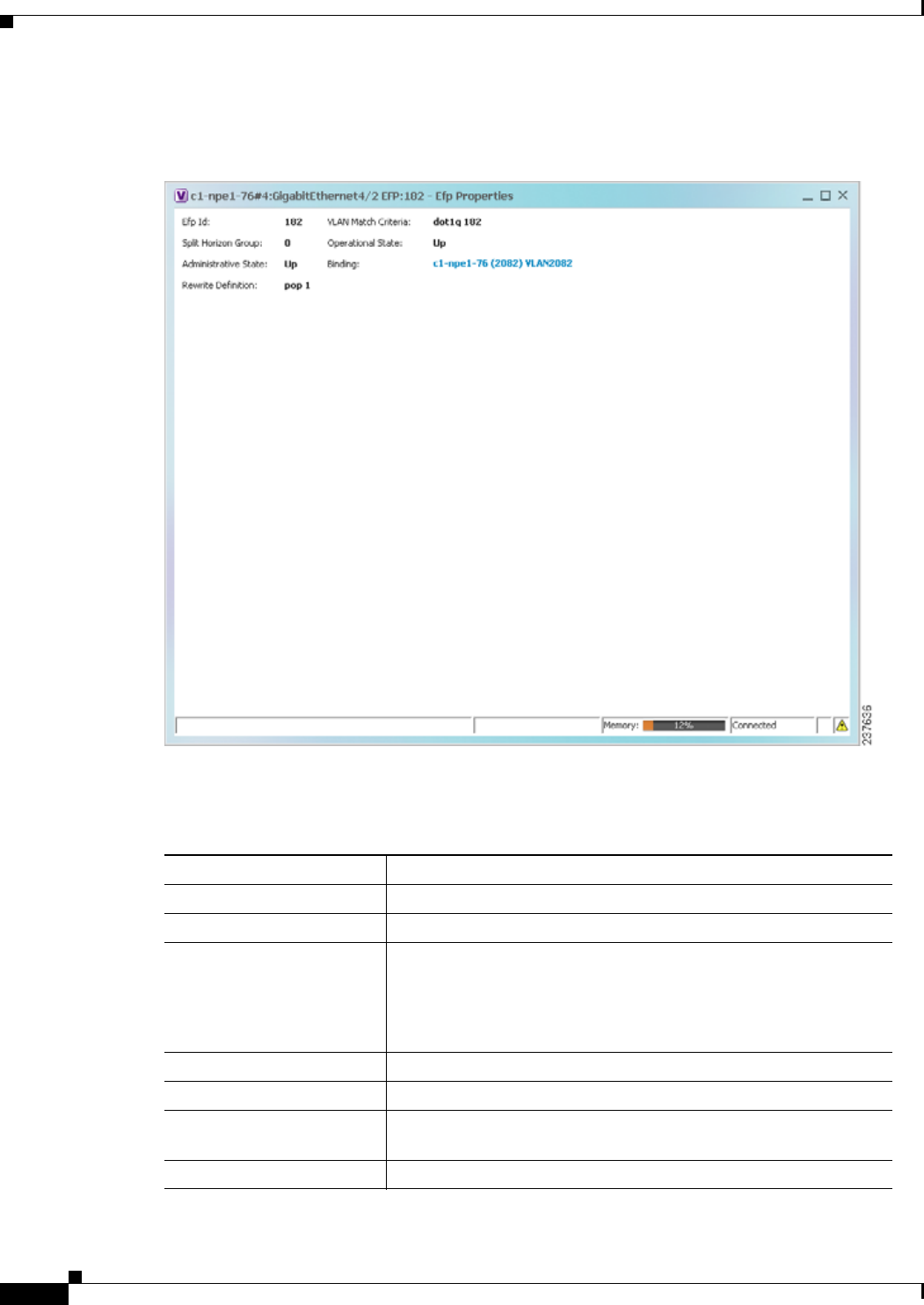
12-34
Cisco Prime Network 4.0 User Guide OL-29343-01
Chapter 12 Monitoring Carrier Ethernet Services
Viewing EFP Properties
Figure 12-13 shows an example of the EFP Properties window.
Figure 12-13 EFP Properties Window
Table 12-19 describes the information displayed in the EFP Properties window.
Table 12-19 EFP Properties Window
Field Description
EFP ID Identifier for the EFP.
VLAN Match Criteria Match criteria configured on the EFP for forwarding decisions.
Split Horizon Group Split horizon group to which the EFP is associated.
If no split horizon group is defined, the value is null.
If only one split horizon group exists and it is enabled for the EFP, the
value is the default group 0.
Operational State Operational status of the EFP: Up or Down.
Administrative State Administrative status of the EFP: Up or Down.
Binding Hyperlinked entry to the relevant item in logical inventory, such as
a pseudowire or bridge.
Rewrite Definition Rewrite command configured on the EFP: pop, push, or translate.
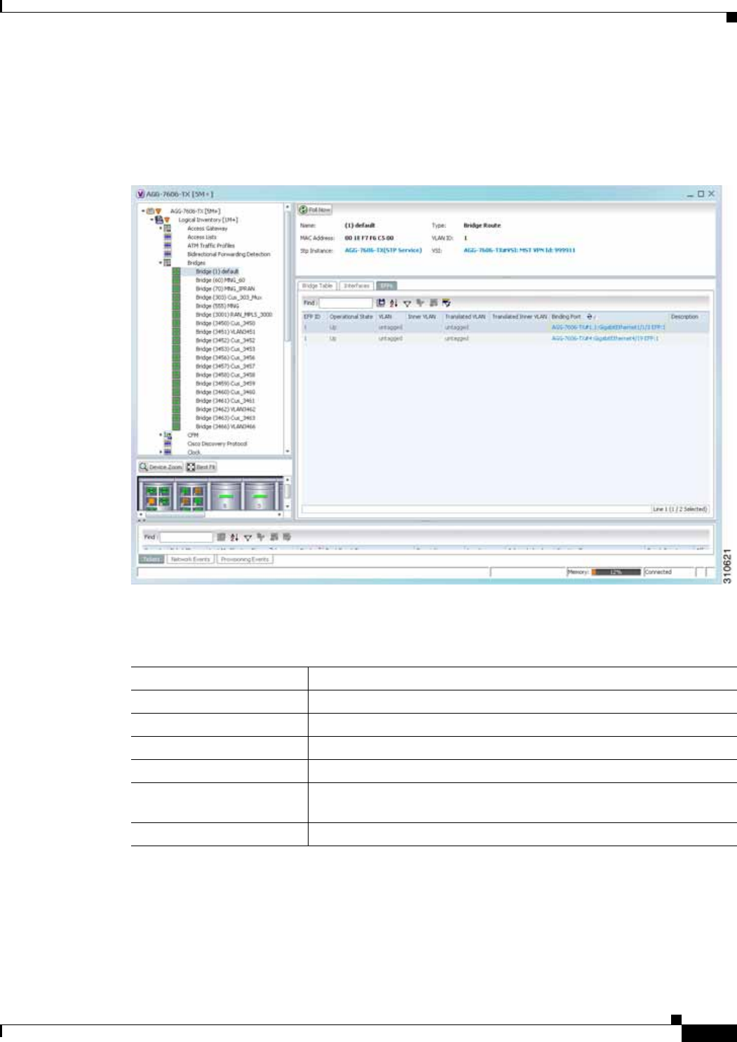
12-35
Cisco Prime Network 4.0 User Guide
OL-29343-01
Chapter 12 Monitoring Carrier Ethernet Services Viewing EFP Properties
Step 2 Click the hyperlink entry in the Binding field to view the related properties in logical inventory.
In this example, clicking the hyperlink displays the relevant bridge in logical inventory, as shown in
Figure 12-14.
Figure 12-14 Bridge Associated with EFP in Logical Inventory
Table 12-20 describes the information displayed for an EFP associated with a bridge.
Table 12-20 EFP Associated with a Bridge in Logical Inventory
Field Description
Name VLAN bridge name.
Type VLAN bridge type.
MAC Address VLAN bridge MAC address.
VLAN ID VLAN bridge VLAN identifier.
STP Instance STP instance information, hyperlinked to the STP entry in logical
inventory.
VSI VSI information, hyperlinked to the VSI entry in logical inventory.

12-36
Cisco Prime Network 4.0 User Guide OL-29343-01
Chapter 12 Monitoring Carrier Ethernet Services
Viewing EFP Properties
Step 3 To view EFP properties in physical inventory, navigate to the required interface in one of the following
ways:
• In the bridge entry in logical inventory, click the hyperlinked entry in the Binding field.
• Use the procedure described in Viewing and Renaming Ethernet Flow Domains, page 12-42 to
navigate to the individual interface.
• In physical inventory, navigate to and then select the required interface.
The EFPs tab is displayed in the content pane next to the Subinterfaces tab as shown in Figure 12-15.
EFPs Table
EFP ID EFP identifier.
Operational State EFP operational state: Up or Down.
VLAN VLAN associated with this EFP.
Inner VLAN CE-VLAN identifier.
Translated VLAN Translated, or mapped, VLAN identifier.
Translated Inner VLAN Translated, or mapped, inner VLAN identifier.
Binding Hyperlinked entry to the specific interface and EFP entry in physical
inventory.
Description Description for the EFP.
Table 12-20 EFP Associated with a Bridge in Logical Inventory (continued)
Field Description
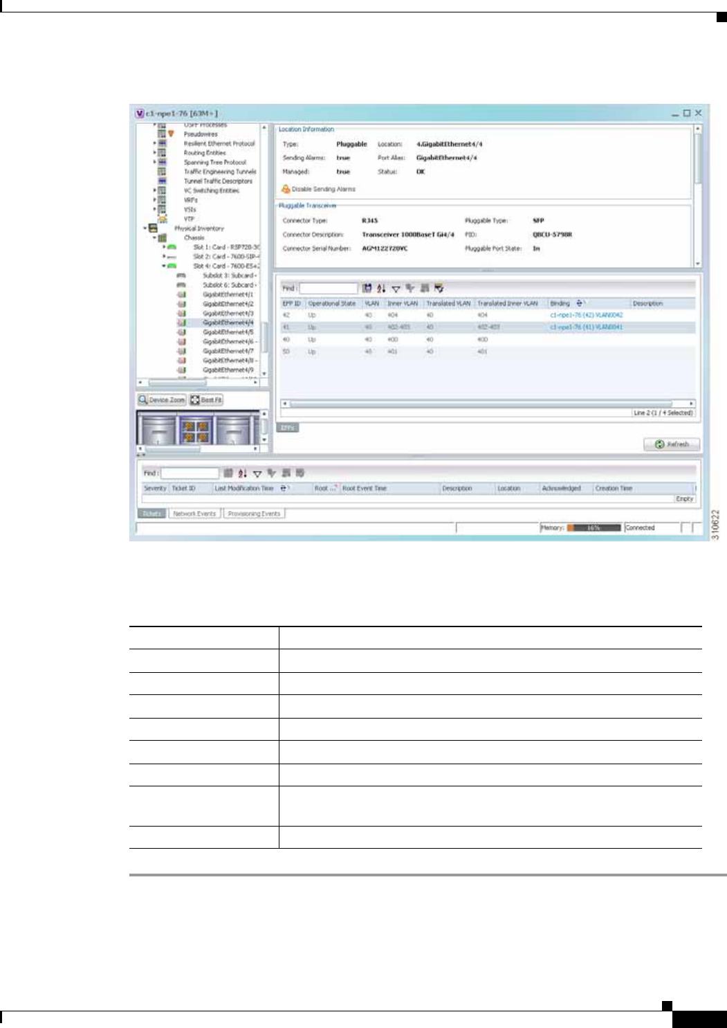
12-37
Cisco Prime Network 4.0 User Guide
OL-29343-01
Chapter 12 Monitoring Carrier Ethernet Services Viewing EFP Properties
Figure 12-15 EFPs Tab in Physical Inventory
Table 12-21 describes the information displayed in the EFPs tab.
Table 12-21 EFPs Tab
Field Description
EFP ID EFP identifier.
Operational State EFP operational state.
VLAN VLAN identifier.
Inner VLAN CE-VLAN identifier.
Translated VLAN Translated VLAN identifier.
Translated Inner VLAN Translated CE-VLAN identifier.
Binding Hyperlinked entry to the specific bridge or pseudowire in logical
inventory.
Description Configured description for the EFP.

12-38
Cisco Prime Network 4.0 User Guide OL-29343-01
Chapter 12 Monitoring Carrier Ethernet Services
Connecting a Network Element to an EFP
Connecting a Network Element to an EFP
You can add and connect network elements to an EFP under an existing aggregation for VLAN, VPLS,
Pseudowire, and Ethernet Service.
To connect network elements to an EFP:
Step 1 Select an EFP node under the VLAN/VPLS/Pseudowire/Ethernet Service aggregation node and choose
File > Add to Map > Network Element.
Step 2 In the Add Network Element dialog box, search for the desired network elements and choose the network
element that you want to add.
The selected network element appears under the aggregation node in the navigation pane.
Step 3 Right-click the EFP node and choose Topology > Connect CE Device.
Step 4 Right-click the network element that you added and choose Topology > Connect to EFP.
The map view displays a link between the EFP and the added network element. If required, you can
remove the link, by right-clicking the link and choosing Remove Link.
Step 5 To hide or show the connected network elements, right-click the EFP node and choose Hide Connected
Devices or Show CE device.
Understanding EFP Severity and Ticket Badges
Severity and ticket badges are displayed on EFP icons as follows:
• If the VLAN EFP element represents a configuration, such as a service instance on a Cisco 7600
device or an enhanced port on a Cisco ASR 9000 device, and is associated directly with a network
VLAN or a bridge domain switching entity, the severity and ticket badges are based on the
underlying service instance or enhanced port configuration.
Figure 12-16 shows an example of a ticket badge based on a service instance.

12-39
Cisco Prime Network 4.0 User Guide
OL-29343-01
Chapter 12 Monitoring Carrier Ethernet Services Understanding EFP Severity and Ticket Badges
Figure 12-16 EFP Severity and Ticket Badges Based on Underlying Service Instance
• If the Ethernet flow point element represents a VLAN interface for a regular switch port, the severity
and ticket badges are based on the corresponding port, as shown in Figure 12-17.
Figure 12-17 EFP Severity and Ticket Badges Based on Corresponding Port

12-40
Cisco Prime Network 4.0 User Guide OL-29343-01
Chapter 12 Monitoring Carrier Ethernet Services
Viewing EVC Service Properties
Viewing EVC Service Properties
Certain EVC service properties are configured as port attributes. These attributes determine the degree
of service transparency and protect the service provider’s network from protocol control traffic. Prime
Network Vision discovers these key EVC service properties and displays this information in physical
inventory for the following devices:
• Cisco ME3400- and Cisco ME3400E-series devices running Cisco IOS versions 12.2(52)SE to
12.2(54)SE.
• Cisco 3750 Metro devices running Cisco IOS versions 12.2(52)SE to 12.2(54)SE.
Shared Switching Entities and EVC Service View
Some switching entities that Prime Network Vision discovers are concurrently part of a network VLAN
and VPLS/EoMPLS instance. These switching entities are referred to as shared switching entities.
Prime Network Vision displays the switching entity information for shared switching entities only under
the VPLS instances in the EVC service view.
To view EVC port-related properties for the supported devices and software versions:
Step 1 In Prime Network Vision, double-click the required device.
Step 2 In the inventory window, choose Physical Inventory > Chassis > module > port.
Figure 12-18 shows an example of a port in physical inventory configured with these EVC properties.
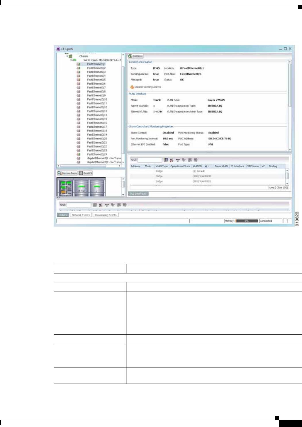
12-41
Cisco Prime Network 4.0 User Guide
OL-29343-01
Chapter 12 Monitoring Carrier Ethernet Services Viewing EVC Service Properties
Figure 12-18 EVC Port Properties in Physical Inventory
Table 12-22 describes the information displayed for these properties.
Table 12-22 EVC Port Properties in Physical Inventory
Field Description
Storm Control and Monitoring Properties Area
Storm Control Status of storm control on the port: Enabled or Disabled.
Port Monitoring Status Status of port monitoring:
• Enabled—The switch sends keepalive messages on user network
interfaces (UNIs) and enhanced network interfaces (ENIs) and does
not send keep alive messages on network node interfaces (NNIs).
• Disabled—The switch does not send keepalive messages.
Port Monitoring Interval Keepalive interval in seconds. The default value is ten seconds.
Storm Control Level Representing a percentage of the total available bandwidth of the port,
the threshold at which additional traffic of the specified type is
suppressed until the incoming traffic falls below the threshold.
Storm Control Type Type of storm the port is configured for protection from: Broadcast,
Multicast, or Unicast.

12-42
Cisco Prime Network 4.0 User Guide OL-29343-01
Chapter 12 Monitoring Carrier Ethernet Services
Viewing and Renaming Ethernet Flow Domains
Viewing and Renaming Ethernet Flow Domains
An Ethernet flow domain represents an Ethernet access domain. The Ethernet flow domain holds all
network elements between the CE (inclusive, if managed by the SP), up to the SP core (exclusive). This
includes CE, access, aggregation, and distribution network elements.
An Ethernet flow domain can have no N-PEs (flat VLAN) or one or more N-PEs (N-PE redundancy
configuration). The Ethernet flow domain is defined using physical connectivity at the port level, and
not at the network element level. STP is used to mark the root bridge, root or blocked ports, and blocked
VLAN links.
Security Properties Areas
Port Security Status of security on the port: Enabled or Disabled.
MAC Address Limit Maximum number of MAC addresses allowed on the interface.
Aging Type Type of aging used for automatically learned addresses on a secure port:
• Absolute—Times out the MAC address after the specified age-time
has been exceeded, regardless of the traffic pattern. This is the
default for any secured port, and the age-time value is set to 0.
• Inactivity—Times out the MAC address only after the specified
age-time of inactivity from the corresponding host has been
exceeded.
Aging Time Length of time, in minutes, that a MAC address can remain on the port
security table.
Violation Mode Action that occurs when a new device connects to a port or when a new
device connects to a port after the maximum number of devices are
connected:
• Protect—Drops packets with unknown source addresses until a
sufficient number of secure MAC addresses are removed to drop
below the maximum value
• Restrict—Drops packets with unknown source addresses until a
sufficient number of secure MAC addresses are removed to drop
below the maximum value and causes the Security Violation counter
to increment.
• Shutdown—Puts the interface into the error-disabled state
immediately and sends an SNMP trap notification.
Table 12-22 EVC Port Properties in Physical Inventory (continued)
Field Description
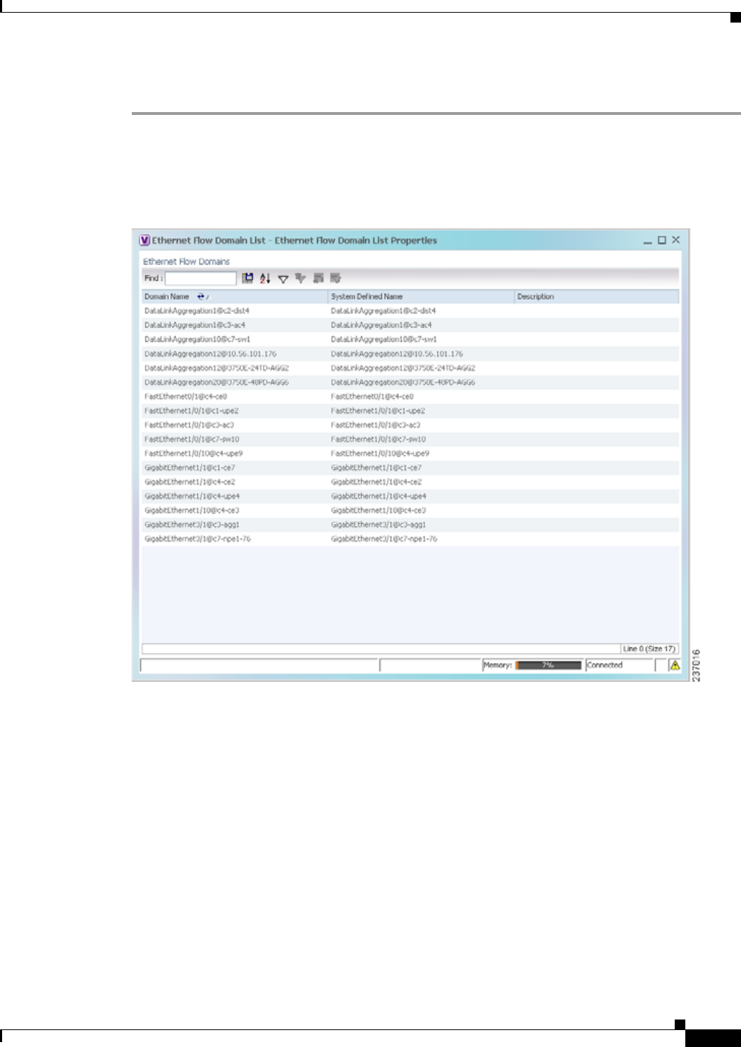
12-43
Cisco Prime Network 4.0 User Guide
OL-29343-01
Chapter 12 Monitoring Carrier Ethernet Services Viewing and Renaming Ethernet Flow Domains
To view Ethernet flow domains:
Step 1 In Prime Network Vision, choose Network Inventory > Ethernet Flow Domains.
The Ethernet Flow Domain List window is displayed with the domain name, the system-defined domain
name, and a brief description for each Ethernet flow domain as shown in Figure 12-19.
Figure 12-19 Ethernet Flow Domain List Properties Window
Step 2 To rename an Ethernet flow domain:
a. Right-click the required domain, then choose Rename.
b. In the Rename Node dialog box, enter a new name for the domain.
c. Click OK.
The window is refreshed, and the new name is displayed.
Step 3 To view Ethernet flow domain properties, do either of the following:
• Right-click the required domain, then choose Properties.
• Double-click the required domain.
The Ethernet Flow Domain Properties window is displayed as shown in Figure 12-20.
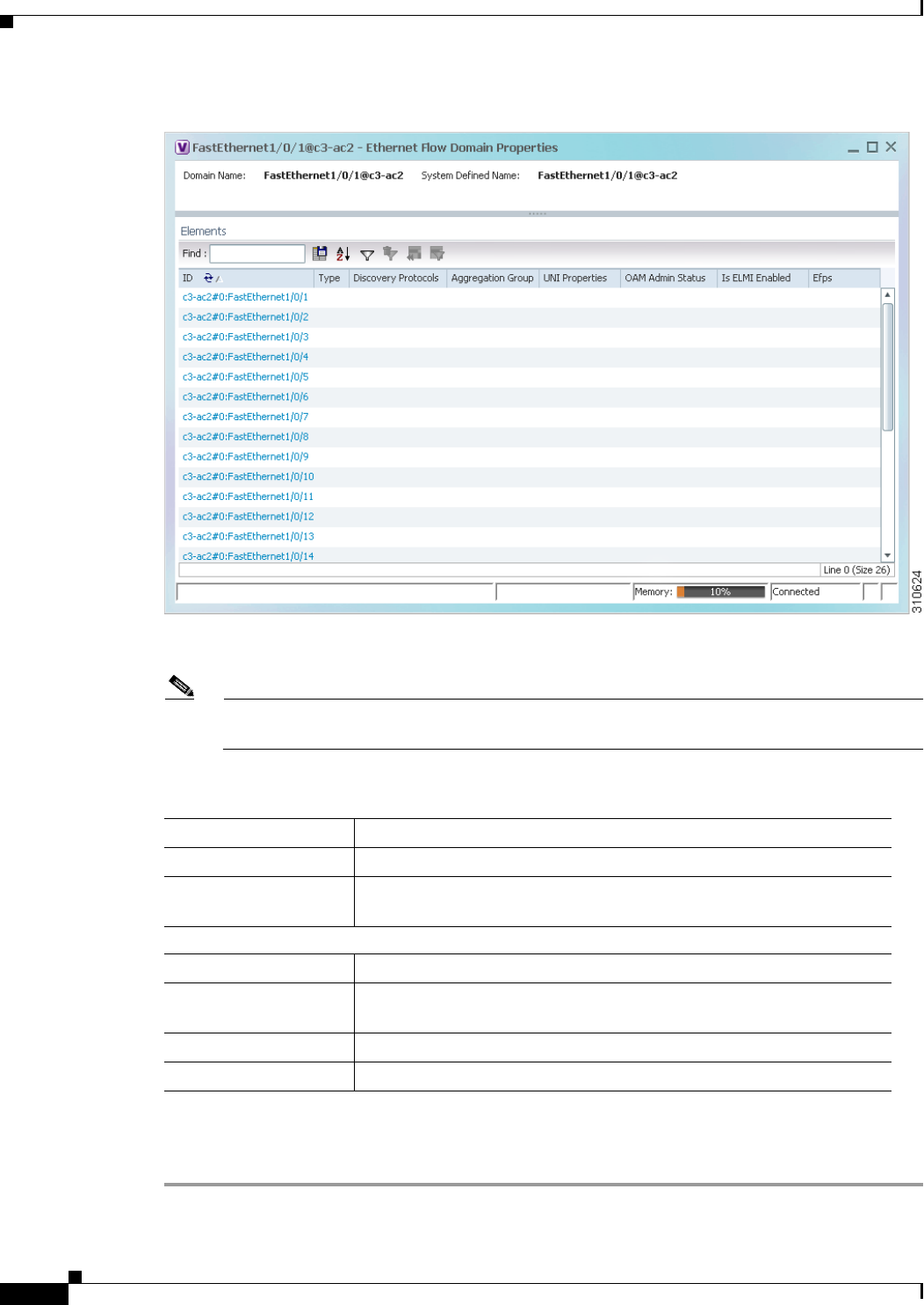
12-44
Cisco Prime Network 4.0 User Guide OL-29343-01
Chapter 12 Monitoring Carrier Ethernet Services
Viewing and Renaming Ethernet Flow Domains
Figure 12-20 Ethernet Flow Domain Properties Window
Table 12-23 describes the information displayed in the Ethernet Flow Domain Properties window.
Note Not all fields are available in all tables. The table contents depend on the domain type, such as
FastEthernet.
Step 4 To navigate to the individual interface or link aggregation group, click an interface identifier or group.
The interface or link aggregation group properties are displayed in the inventory window.
Table 12-23 Ethernet Flow Domain Properties Window
Field Description
Domain Name Name of the selected domain.
System Defined Name Domain name as identified by the most dominant device and its lowest
port name lexicographically.
Elements Table
ID Interface identifier, hyperlinked to the interface in physical inventory.
Type Aggregation group type: Ethernet Channel (EtherChannel), or IEEE
8023 AD LAG (IEEE 802.3 link aggregation group).
Discovery Protocols Discovery protocols used on the interface.
Is ELMI Enabled Whether or not Ethernet LMI is enabled on the interface: True or False.

12-45
Cisco Prime Network 4.0 User Guide
OL-29343-01
Chapter 12 Monitoring Carrier Ethernet Services Working with VLANs
Working with VLANs
The following topics provide information and procedures for working with VLANs. The Vision GUI
client supports a VLAN overlay which, when applied, highlights the network elements and links that a
VLAN (and its associated VLANs) traverse. The overlay displays STP and REP link and port
information. Using overlays is described in Displaying VLANs By Applying VLAN Overlays to a
Map45, page 12-61.
• Understanding VLAN and EFD Discovery, page 12-45
• Understanding VLAN Elements, page 12-46
• Switching Entities Containing Termination Points, page 12-50
• Adding and Removing VLANs from a Map, page 12-50
• Viewing VLAN Mappings, page 12-53
• Working with Associated VLANs, page 12-55
• Viewing VLAN Links Between VLAN Elements and Devices, page 12-58
• Displaying VLANs By Applying VLAN Overlays to a Map45, page 12-61
• Viewing VLAN Service Link Properties, page 12-63
• Viewing REP Information in VLAN Domain Views and VLAN Overlays, page 12-63
• Viewing REP Properties for VLAN Service Links, page 12-64
• Viewing STP Information in VLAN Domain Views and VLAN Overlays, page 12-66
• Viewing STP Properties for VLAN Service Links, page 12-67
• Viewing VLAN Trunk Group Properties, page 12-68
• Viewing VLAN Bridge Properties, page 12-70
• Using Commands to Work With VLANs, page 12-72
Understanding VLAN and EFD Discovery
When you start the Prime Network gateway the first time, Prime Network Vision waits for two topology
cycles to complete before discovering new VLANs, VLAN associations, and EFDs. The default
configured time for two topology cycles to complete is one hour, but might be configured for longer
periods of time on large setups. This delay allows the system to stabilize, and provides the time needed
to model devices and discover links.
During this delay, Prime Network Vision does not add VNEs or apply updates to existing VLANs or
EFDs.
After the initial delay has passed, Prime Network Vision discovers new VLANs, VLAN associations,
and EFDs, applies updates to existing VLANs, VLAN associations, and EFDs, and updates the database
accordingly.
When you restart the gateway, Prime Network Vision uses the persisted topology information instead of
waiting two topology cycles, thus improving the discovery time for new VLANs, VLAN associations,
and EFDs.

12-46
Cisco Prime Network 4.0 User Guide OL-29343-01
Chapter 12 Monitoring Carrier Ethernet Services
Working with VLANs
Understanding VLAN Elements
The following concepts are important to understand when working with the representation of edge EFPs
inside VLANs:
• VLAN Elements in Prime Network Vision, page 12-46
• VLANs, page 12-46
• Switching Entities, page 12-46
• Ethernet Flow Points, page 12-47
VLAN Elements in Prime Network Vision
Table 12-24 describes the icons that Prime Network Vision uses to represent VLAN elements.
VLANs
Prime Network Vision discovers and allows you to display maps with a network-level view of VLANs.
In Prime Network, a VLAN entity consists of one or more switching entities and the corresponding EFP
elements.
A network VLAN represents the virtual LAN. The network VLAN holds its contained switching entities
and can be associated to a customer. The network VLAN also holds the Ethernet flow points that are part
of the network VLAN but not part of any switching entity. For example, a port that tags ingress flows
after which the flow moves to a different VLAN.
Switching Entities
A switching entity represents a device-level Layer 2 forwarding entity (such as a VLAN or bridge
domain) that participates in a network VLAN. A switching entity is associated to a network VLAN
according to its relationship to the same Ethernet Flow Domain (EFD) and the VLAN identifier.
If you right-click a switching entity in Prime Network Vision and then choose Inventory, the inventory
window is displayed with the corresponding bridge selected in Logical Inventory.
A switching entity typically contains EFP elements.
Table 12-24 VLAN Elements and Icons in Prime Network Vision
Element Associated Network Element Icon
Network VLAN None
Switching entity Bridge
Ethernet Flow Point (EFP) Ethernet port
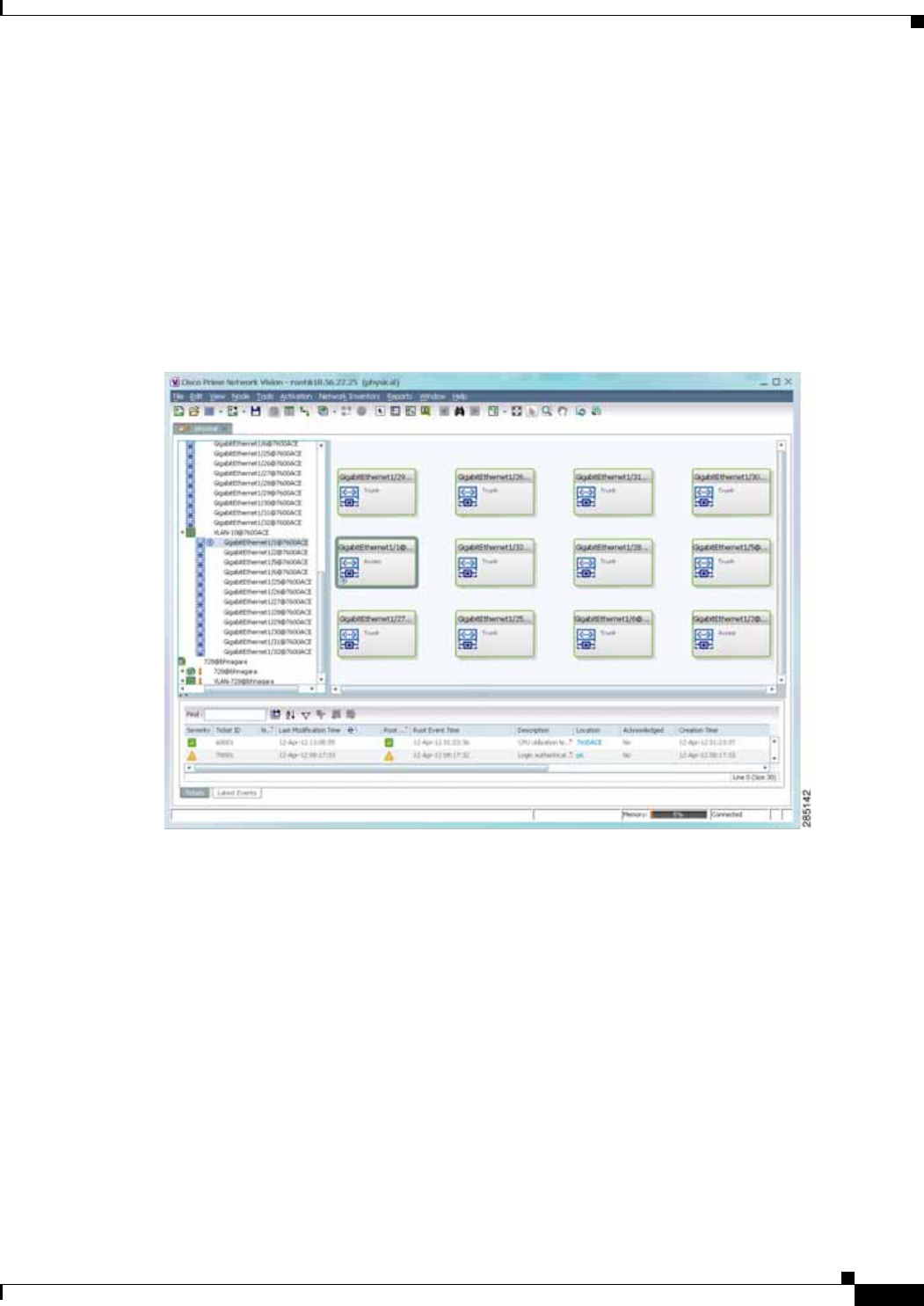
12-47
Cisco Prime Network 4.0 User Guide
OL-29343-01
Chapter 12 Monitoring Carrier Ethernet Services Working with VLANs
Ethernet Flow Points
An Ethernet flow point (EFP) can represent a port that is configured for participation in a specific
VLAN.
If you right-click an EFP in Prime Network Vision and then choose Inventory, the inventory window is
displayed with the corresponding port selected in Physical Inventory.
EFPs that are located in a switching entity represent Ethernet ports that are configured as switch ports
(in either Access, Trunk, or Dot1Q tunnel mode).
Figure 12-21 shows an example of EFPs configured as switch ports in Prime Network Vision.
Figure 12-21 EFPs Configured as Switch Ports
EFPs that are located directly inside a VLAN represent one of the following:
• Termination point EFPs—Ethernet ports that are at the edge of a Layer 2 domain flow, such as a
VLAN, on which traffic enters a Layer 3 domain or a different Layer 2 domain, such as EoMPLS.
These ports are found on such devices as the Cisco 7600 series, Cisco GSR, and Cisco ASR 9000
series devices.
These EFPs are typically connected to a switching entity inside the VLAN by a VLAN link, as
shown in Figure 12-22.
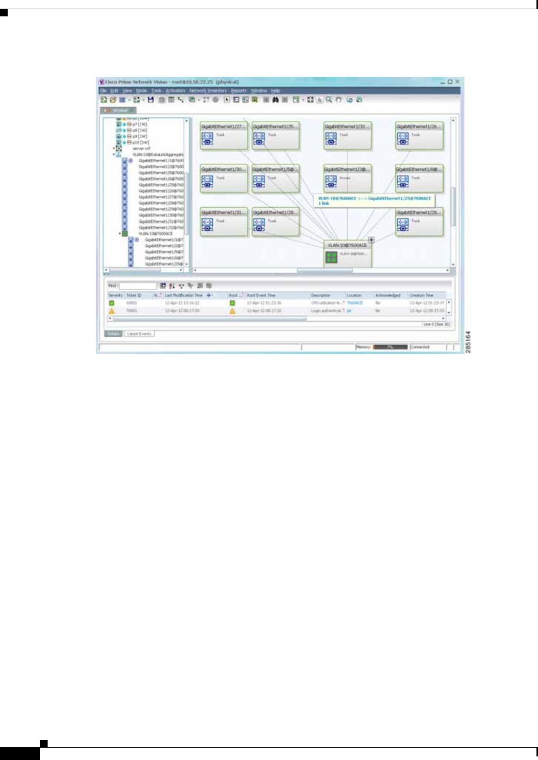
12-48
Cisco Prime Network 4.0 User Guide OL-29343-01
Chapter 12 Monitoring Carrier Ethernet Services
Working with VLANs
Figure 12-22 Termination Point EFP Inside a VLAN
• Edge EFPs—A subset of EFPs that exist inside a switching entity but that are not connected to other
EFPs and that represent edge EFPs in the context of the VLAN.
In Prime Network Vision, edge EFPs are displayed directly under the VLAN at the same level as their
switching entities and are connected to their corresponding switching entities by a dotted link, as shown
in Figure 12-23.
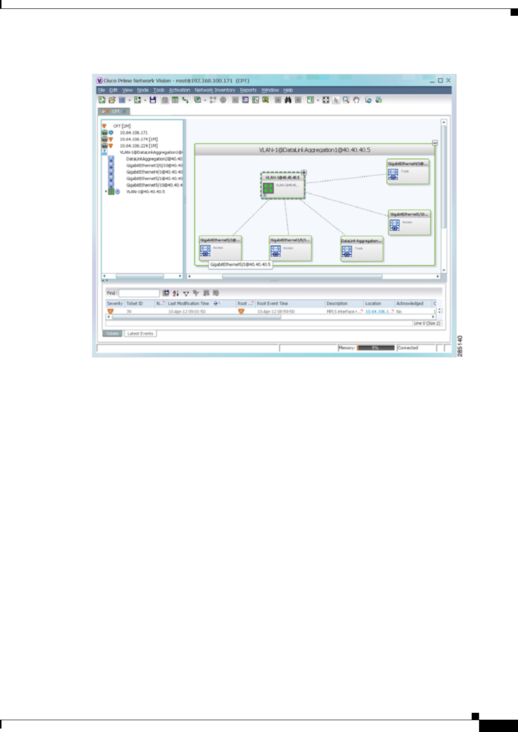
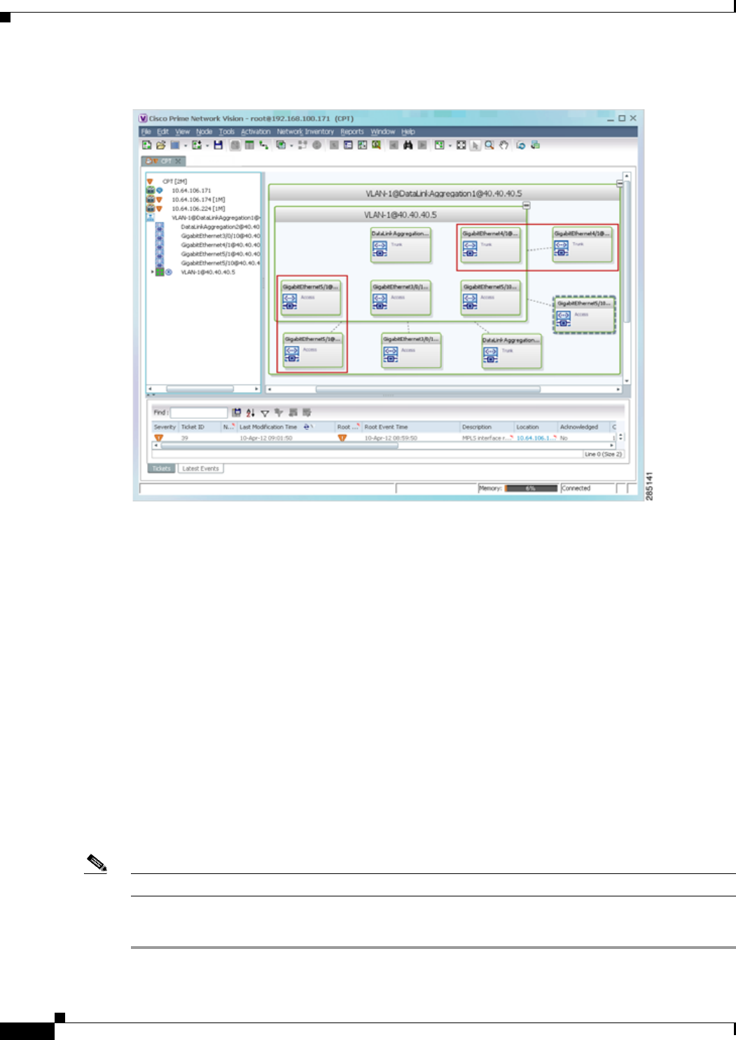
12-50
Cisco Prime Network 4.0 User Guide OL-29343-01
Chapter 12 Monitoring Carrier Ethernet Services
Working with VLANs
Figure 12-24 Edge EFPs Displayed Inside and Outside of Switching Entities
You can delete EFPs and switching entities that have a reconciliation icon by right-clicking them and
choosing Delete. After all switching entities and EFPs are deleted from a network VLAN, the empty
network VLAN is automatically deleted from Prime Network Vision after a few minutes.
Switching Entities Containing Termination Points
For some devices, such as Cisco 7600 series, Cisco GSR, and Cisco ASR 9000 series devices, the related
switching entities can contain Ethernet flow point elements that serve as termination points on different
network VLANs. If a single map contains both the switching entities and the network VLANs, a link is
displayed between them.
Adding and Removing VLANs from a Map
Adding VLANs to a Map
You can add VLANs to a map if the VLANs were previously discovered by Prime Network Vision and
are not currently displayed in the map.
Note Adding VLANs affects other users if they are working with the same map.
To add VLANs to a map:
Step 1 In Prime Network Vision, display the map to which you want to add the VLANs.
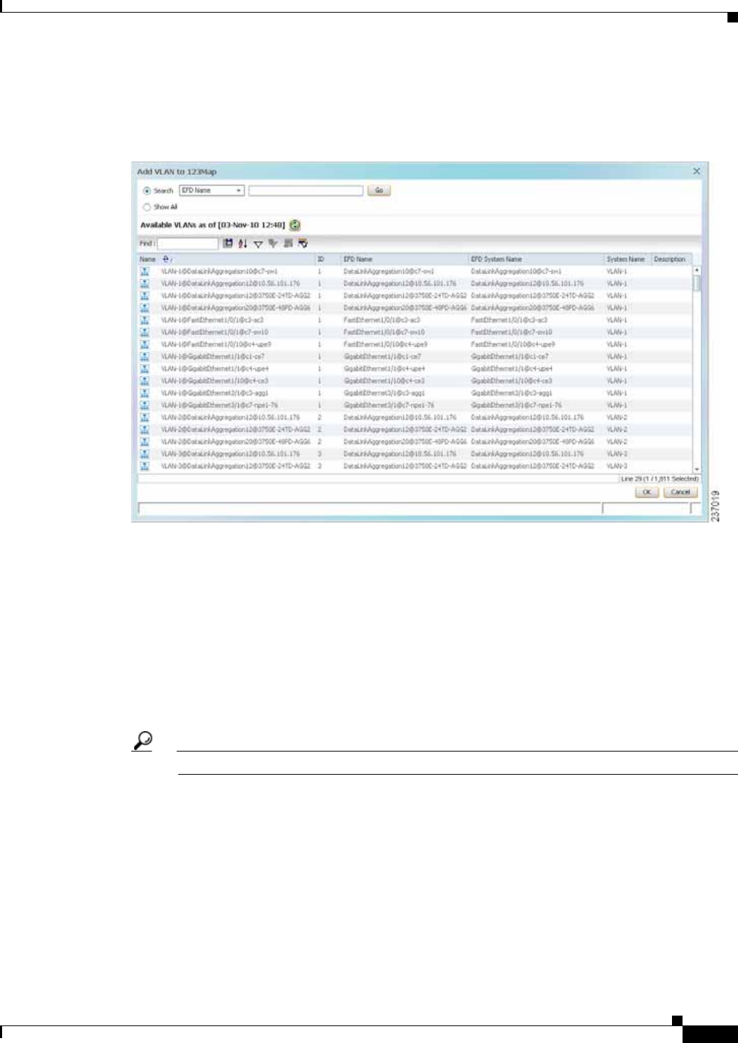
12-51
Cisco Prime Network 4.0 User Guide
OL-29343-01
Chapter 12 Monitoring Carrier Ethernet Services Working with VLANs
Step 2 Choose File > Add to Map > VLAN. The Add VLAN to map dialog box is displayed as shown in
Figure 12-25.
Figure 12-25 Add VLAN Dialog Box
Step 3 In the Add VLAN dialog box, do either of the following:
• Choose a search category, enter a search string, then click Go to narrow the VLAN display to a range
of VLANs or a specific VLAN.
The search condition is “contains.” Search strings are case-insensitive. For example, if you choose
the Name category and enter “net,” Prime Network Vision displays VLANs that have “net”
anywhere in their names. The string “net” can be at the beginning, the middle, or end of the name,
such as Ethernet.
• Choose Show All to display all the VLANs.
Step 4 Select the VLANs that you want to add to the map.
Tip Press Shift or Ctrl to choose multiple adjoining or nonconsecutive VLANs.
Step 5 Click OK.
The VLANs are displayed in the Prime Network Vision content pane as shown in Figure 12-26.
Any tickets that apply to the VLANs are displayed in the ticket pane.
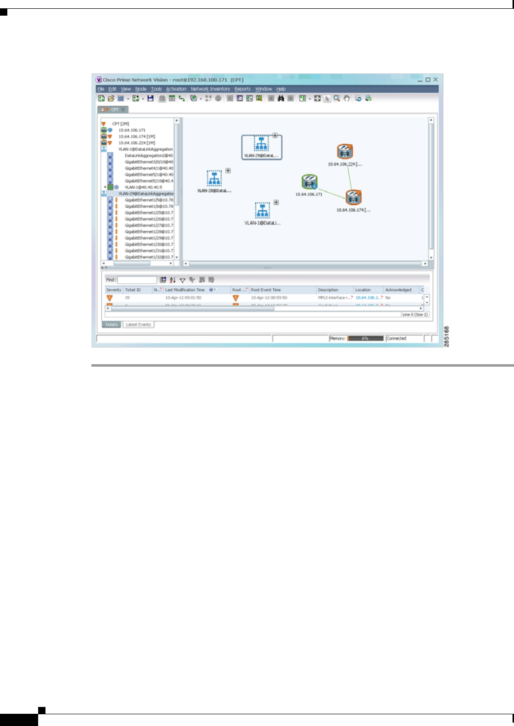
12-52
Cisco Prime Network 4.0 User Guide OL-29343-01
Chapter 12 Monitoring Carrier Ethernet Services
Working with VLANs
Figure 12-26 VLANs in Map View
After you add a VLAN to a map, you can use Prime Network Vision to view its switching entities and
Ethernet flow points. For more information, see:
• Viewing and Renaming Ethernet Flow Domains, page 12-42
• Viewing EFP Properties, page 12-33
You can view additional information about REP and STP in logical inventory, VLAN domain views, and
VLAN overlays.
For REP, see:
• Viewing Resilient Ethernet Protocol Properties (REP), page 12-14
• Viewing REP Information in VLAN Domain Views and VLAN Overlays, page 12-63
• Viewing REP Properties for VLAN Service Links, page 12-64
For STP, see:
• Viewing Spanning Tree Protocol Properties, page 12-10
• Viewing STP Information in VLAN Domain Views and VLAN Overlays, page 12-66
• Viewing STP Properties for VLAN Service Links, page 12-67
Removing VLANs From a Map
You can remove one or more VLANs from the current map. This change does not affect other maps.
Removing a VLAN from a map does not remove it from the Prime Network database. You can add the
VLAN to the map at any time.

12-53
Cisco Prime Network 4.0 User Guide
OL-29343-01
Chapter 12 Monitoring Carrier Ethernet Services Working with VLANs
When removing VLANs from maps, keep the following in mind:
• Removing a VLAN affects other users who are working with the same map view.
• This option does not change the business configuration or database.
• You cannot remove virtual routers or sites from the map without removing the VLAN.
To remove a VLAN, in the Prime Network Vision navigation pane or map view, right-click the VLAN
and choose Remove from Map.
The VLAN is removed from the navigation pane and map view along with all VLAN elements such as
connected CE devices. Remote VLANs (extranets) are not removed.
Viewing VLAN Mappings
VLAN mapping, or VLAN ID translation, is used to map customer VLANs to service provider VLANs.
VLAN mapping is configured on the ports that are connected to the service provider network. VLAN
mapping acts as a filter on these ports without affecting the internal operation of the switch or the
customer VLANs.
If a customer wants to use a VLAN number in a reserved range, VLAN mapping can be used to overlap
customer VLANs by encapsulating the customer traffic in IEEE 802.1Q tunnels.
To view VLAN mappings:
Step 1 In Prime Network Vision, double-click the device with VLAN mappings configured.
Step 2 In the inventory window, choose Physical Inventory > Chassis > slot > port.
Step 3 Click VLAN Mappings next to the Subinterfaces tab in the lower portion of the content pane.
The VLAN Mappings tab is displayed as shown in Figure 12-27.
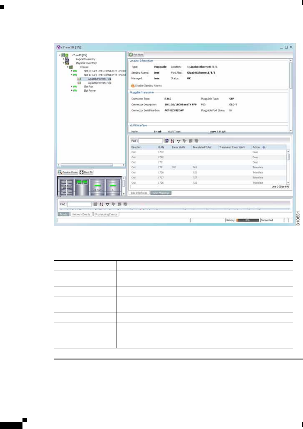
12-54
Cisco Prime Network 4.0 User Guide OL-29343-01
Chapter 12 Monitoring Carrier Ethernet Services
Working with VLANs
Figure 12-27 VLAN Mappings Tab in Physical Inventory
Table 12-25 describes the information that is displayed in the VLAN Mappings table.
Table 12-25 VLAN Mappings Table
Field Description
Direction Whether the VLAN mapping is defined in the incoming or outgoing
direction: In or Out.
VLAN Customer-side VLAN identifier.
Inner VLAN Used for two-to-one mappings, the customer-side inner VLAN
identifier.
Translated VLAN Translated, or mapped, service-provider side VLAN identifier.
Translated Inner VLAN Translated, or mapped, service-provider side inner VLAN identifier.
Action Action taken if the VLAN traffic meets the specified mapping: Translate
or Drop.

12-55
Cisco Prime Network 4.0 User Guide
OL-29343-01
Chapter 12 Monitoring Carrier Ethernet Services Working with VLANs
Working with Associated VLANs
Prime Network Vision discovers associations between network VLANs and displays the information in
Prime Network Vision. Network VLAN associations are represented by VLAN service links, and can be
any of the tag manipulation types described in Table 12-26.
When working with VLANs, you can:
• Add an associated VLAN—See Adding an Associated VLAN, page 12-55.
• View properties for associated VLANs—See Viewing Associated Network VLAN Service Links
and VLAN Mapping Properties, page 12-57.
Adding an Associated VLAN
To add an associated VLAN to an existing VLAN in a map:
Step 1 In Prime Network Vision, select the required VLAN in the map view.
Step 2 Right-click the VLAN and choose Add Associated VLAN.
The Add Associated VLAN table is displayed as shown in Figure 12-28.
Table 12-26 Types of Tag Manipulations in VLAN Associations
VLAN Tag Manipulation Description Example
One-to-one One VLAN tag is translated to
another VLAN tag. VLAN tag 100 > VLAN tag 200
Two-to-two • Two VLAN tags exist and both
are translated to other tags.
• Two VLAN tags exist, but tag
manipulation is applied only to
the outer tag.
• Inner tag 100, Outer tag 101 >
Inner tag 200, Outer tag 201
• Inner tag 100, Outer tag 101 >
Inner tag 100, Outer tag 201
One-to-two One VLAN tag exists and an
additional tag is inserted into the
packet.
VLAN tag 100 > Inner tag 100,
Outer tag 101
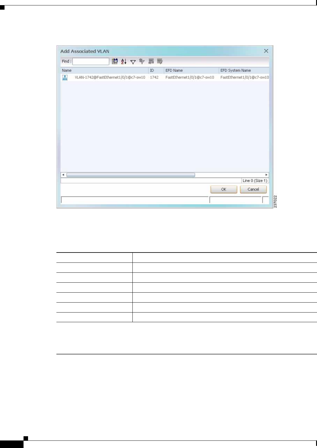
12-56
Cisco Prime Network 4.0 User Guide OL-29343-01
Chapter 12 Monitoring Carrier Ethernet Services
Working with VLANs
Figure 12-28 Add Associated VLAN Window
In this example, the selected network VLAN has one associated VLAN: VLAN-1742.
Table 12-27 describes the information displayed in the Add Associated VLAN table.
Step 3 Select the required VLAN in the Add Associated VLAN table, then click OK.
The associated network VLAN is added to the map in Prime Network Vision.
Table 12-27 Add Associated VLAN Table
Field Description
Name Name of the VLAN.
ID VLAN identifier.
EFD Name Name of the Ethernet flow domain.
EFD System Name Name that Prime Network assigns to the EFD.
System Name Name that Prime Network assigns to the VLAN.
Description Brief description of the VLAN.
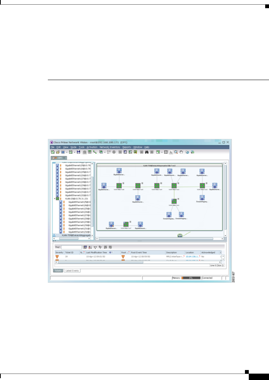
12-57
Cisco Prime Network 4.0 User Guide
OL-29343-01
Chapter 12 Monitoring Carrier Ethernet Services Working with VLANs
Viewing Associated Network VLAN Service Links and VLAN Mapping Properties
After you add an associated network VLAN, you can:
• View the associated network VLAN service links in Prime Network Vision in the thumbnail view.
• View VLAN mapping properties in the Link Properties window.
To view associated network VLAN service links and VLAN mapping properties:
Step 1 Select the required network VLAN in the map view.
Step 2 Right-click the VLAN, then choose Show Thumbnail.
Figure 12-29 shows an example of a network VLAN in a thumbnail.
The VLAN service links are displayed as lines between the associated network VLANs. The links
represent the connections between the Ethernet flow points that are part of each network VLAN.
Figure 12-29 VLAN Service Links Between Associated Network VLANs
Step 3 To view additional information, right-click a link, and choose Properties.
The Link Properties window is displayed as shown in Figure 12-30.

12-58
Cisco Prime Network 4.0 User Guide OL-29343-01
Chapter 12 Monitoring Carrier Ethernet Services
Working with VLANs
If VLAN tag manipulation is configured on the link, the VLAN Mapping Properties area in the Link
Properties window displays the relevant information. For example, in Figure 12-30, the VLAN Mapping
Properties area shows that a one-to-one VLAN mapping for VLAN tag 1709 to VLAN tag 709 is
configured on GigabitEthernet1/1/1 on c7-sw8 on the egress direction.
Figure 12-30 VLAN Mapping Properties in Link Properties Window
For additional information about viewing network VLAN service link properties, see:
• Viewing REP Properties for VLAN Service Links, page 12-64
• Viewing STP Properties for VLAN Service Links, page 12-67
Viewing VLAN Links Between VLAN Elements and Devices
If a Prime Network Vision map contains a VLAN and the network element on which the VLAN is
configured, along with EFPs, switching entities, or network VLANs, you might see what appear to be
multiple associations between the logical and physical entities. Actually, however, you are seeing other
views of the original VLAN link.
For example, assume that you have the following situation, as shown in Figure 12-31 and described in
the following paragraphs.
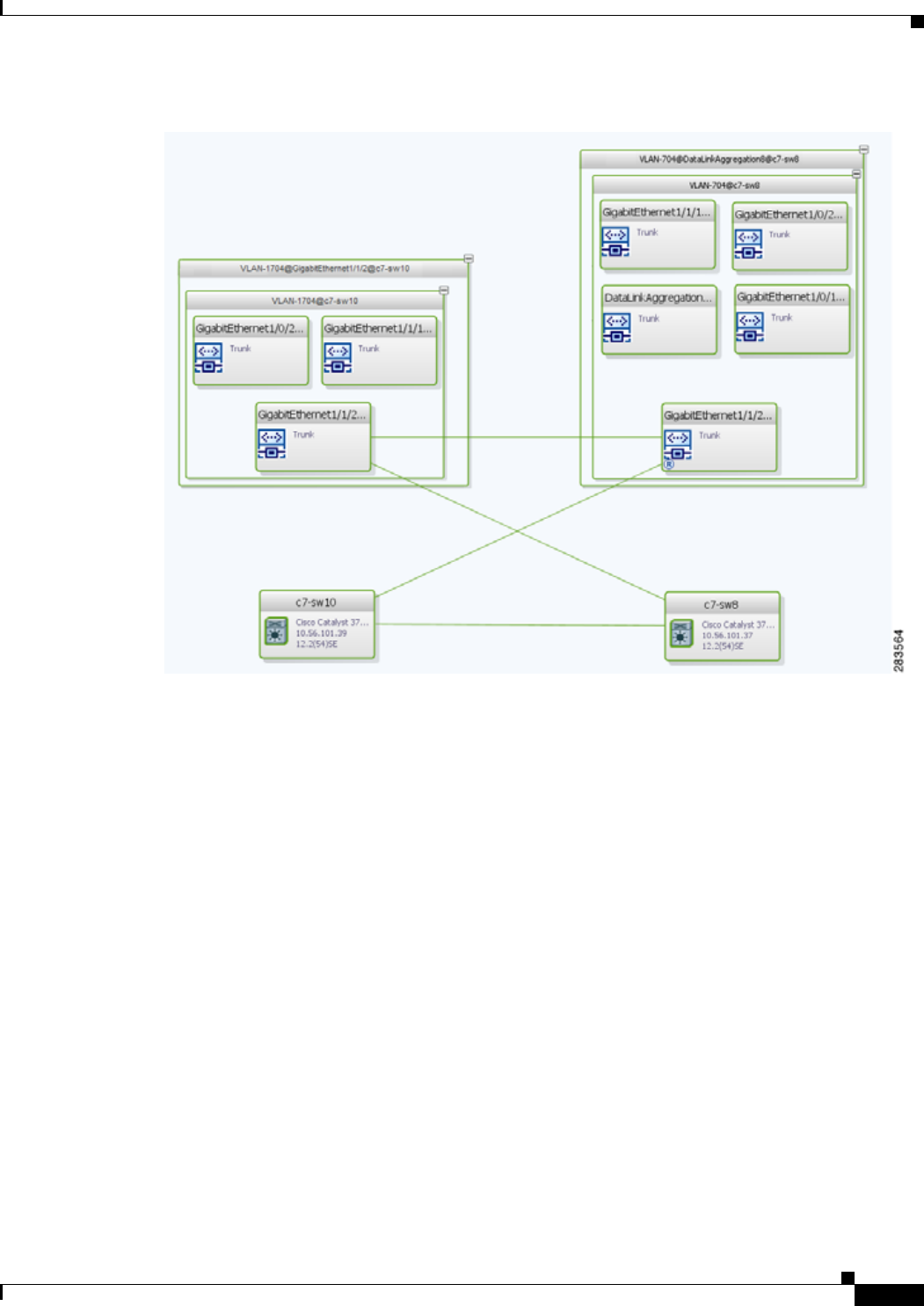
12-59
Cisco Prime Network 4.0 User Guide
OL-29343-01
Chapter 12 Monitoring Carrier Ethernet Services Working with VLANs
Figure 12-31 VLAN Elements and Devices in Prime Network Vision
The elements are configured as follows:
• Port GigabitEthernet1/1/2 on element c7-sw10 is connected to port GigabitEthernet1/1/2 on element
c7-sw8 by an Ethernet topology link.
• Port GigabitEthernet1/1/2 on element c7-sw10 is a trunk port associated with VLAN-1704 which is
configured on element c7-sw10.
• Port GigabitEthernet1/1/2 on element c7-sw8 is a trunk port associated with VLAN-704 which is
configured on element c7-sw8.
• Port GigabitEthernet1/1/2 on element c7-sw8 has a VLAN mapping to tunnel VLAN-1704
(C-VLAN) in VLAN-704 (SP-VLAN).
In this example, VLAN discovery identified two network VLANs: VLAN-1704 and VLAN-704. Each
of these network VLANs contains a switching entity and an EFP that represent the connected ports,
GigabitEthernet1/1/2@c7-sw10 and GigabitEthernet1/1/2@c7-sw8, respectively.
The four links in the map are identified in Figure 12-32 and described in the following table.
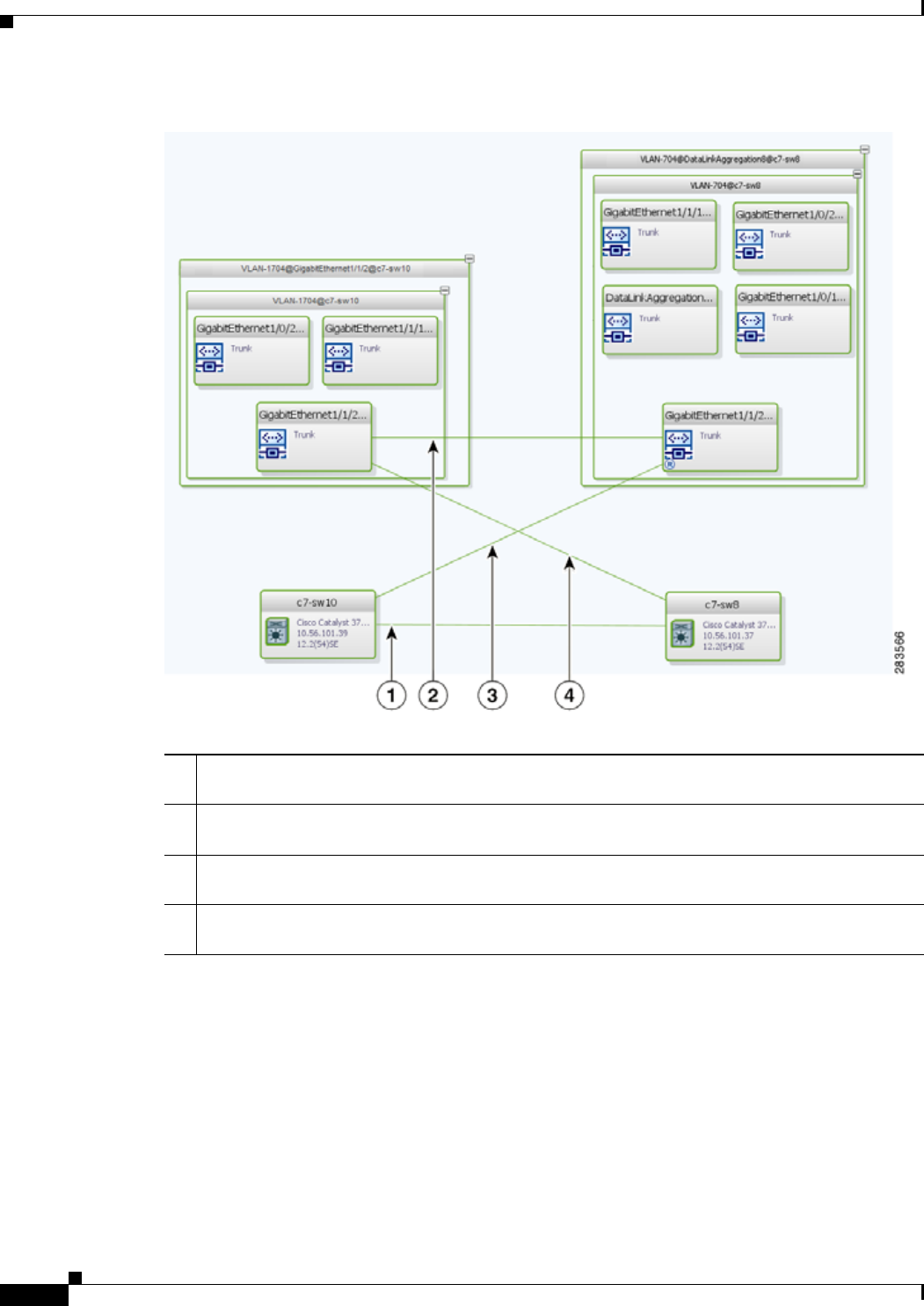
12-60
Cisco Prime Network 4.0 User Guide OL-29343-01
Chapter 12 Monitoring Carrier Ethernet Services
Working with VLANs
Figure 12-32 Links Between VLAN Elements and Devices
The key point is that a link between a VNE and EFP, switching entity, or network VLAN does not
represent an association between the VNE and the logical element. Such a link is simply another view
of the VLAN link.
If the thumbnail view is closed, instead of a link between the VNE and EFP, you will see a link between
the VNE and the switching entity or network VLAN.
1The Ethernet topological link between port GigabitEthernet1/1/2 on VNE c7-sw10 and
GigabitEthernet1/1/2 on VNE c7-sw8.
2The VLAN link between GigabitEthernet1/1/2@c7-sw10 EFP and GigabitEthernet1/1/2@c7-sw8
EFP.
3Another view of the VLAN link (link 2), shown as a link between GigabitEthernet1/1/2@c7-sw10
EFP and GigabitEthernet1/1/2@c7-sw8 EFP.
4Another view of the VLAN link (link 2), shown as a link between GigabitEthernet1/1/2@c7-sw10
EFP and GigabitEthernet1/1/2@c7-sw8 EFP.

12-61
Cisco Prime Network 4.0 User Guide
OL-29343-01
Chapter 12 Monitoring Carrier Ethernet Services Working with VLANs
Displaying VLANs By Applying VLAN Overlays to a Map45
You can create an overlay of a specific VLAN on top of the physical network elements displayed in a
map view. The overlay highlights the network elements and links that the selected VLAN and its
associated VLANs traverse. Network elements and links that are not part of the VLAN are dimmed in
the map view.
The VLAN overlay is a snapshot of the network to help you visualize the network elements and links
connected to a VLAN. The overlay displays STP and REP link and port information.
If you select a network VLAN that is associated with other VLANs, the associated VLANs are included
in the overlay.
The VLAN service overlay allows you to isolate the parts of a network that are being used by a particular
service. This information can then be used for troubleshooting. For example, the overlay can highlight
configuration or design problems when bottlenecks occur and all site interconnections use the same link.
Adding a VLAN Overlay
To add a VLAN overlay:
Step 1 Display the network map for which you want to create an overlay in Prime Network Vision.
Step 2 In the toolbar, choose Choose Overlay Type > VLAN.
Step 3 In the Select VLAN Overlay dialog box, do either of the following:
• Choose a search category, enter a search string, then click Go to narrow the selection to a set of
overlays or a specific overlay.
The search condition is “contains.” Search strings are case-insensitive. For example, if you choose
the Name category and enter “net,” Prime Network Vision displays overlays that have “net” in their
names. The string “net” can be at the beginning, middle, or end of the name, such as Ethernet.
• Choose Show All to view all overlays.
Step 4 Select an overlay, then click OK.
The network elements and physical links used by the selected VLAN overlay are highlighted in the
network map. All other network elements and links are dimmed. The VLAN name is displayed in the
title of the window. See Figure 12-33.
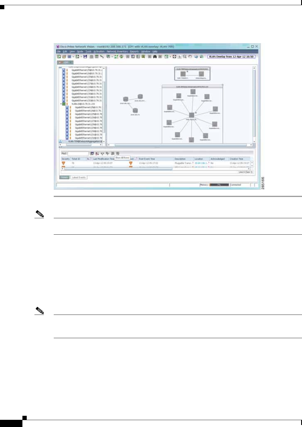
12-62
Cisco Prime Network 4.0 User Guide OL-29343-01
Chapter 12 Monitoring Carrier Ethernet Services
Working with VLANs
Figure 12-33 VLAN Overlay Example
Note The overlay is a snapshot taken at a specific point in time. As a result, the information in the overlay
might become stale. To update the overlay, click Refresh the Last Selected Overlay in the toolbar.
The VLAN overlay service also supports multi-chassis devices. If a network element in the overlay is
dimmed, then all the hosts of the network element along with the Inter Rack Links (IRL) and the Inter
Chassis Links (ICL) used for transportation will also be dimmed. Apart from these, the chassis that holds
the configured port will also be dimmed.
Displaying or Hiding VLAN Overlays
After you create a VLAN overlay, you can hide it by clicking Hide Overlay in the toolbar. All previously
dimmed network elements and links are displayed. To display the overlay, click Show Overlay.
Note The Overlay icon toggles between Show Overlay and Hide Overlay. When selected, the VLAN overlay
is displayed and the Hide Overlay tool is active. When deselected, the VLAN overlay is hidden and the
Show Overlay tool is active.
Removing a VLAN Overlay
To remove a VLAN overlay from a map, choose Choose Overlay Type > None in the toolbar. The
overlay is removed from the map, and the Show Overlay/Hide Overlay icon is dimmed.
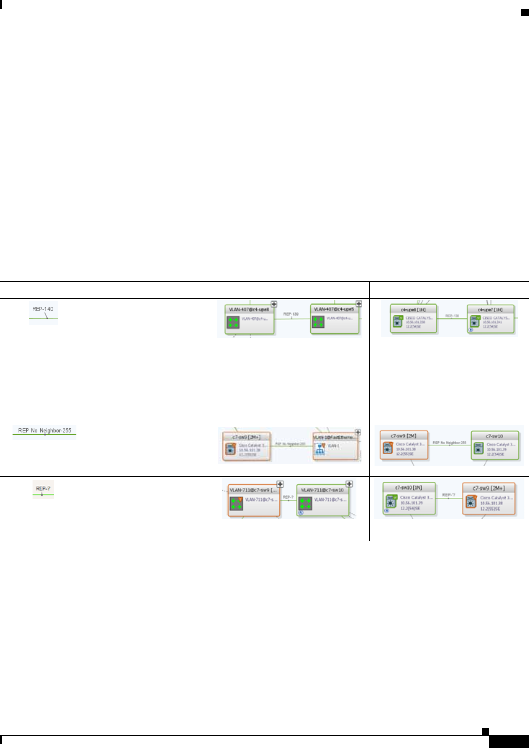
12-63
Cisco Prime Network 4.0 User Guide
OL-29343-01
Chapter 12 Monitoring Carrier Ethernet Services Working with VLANs
Viewing VLAN Service Link Properties
See the following topics for information on viewing VLAN service link properties:
• Viewing REP Properties for VLAN Service Links, page 12-64
• Viewing STP Properties for VLAN Service Links, page 12-67
• Viewing Associated Network VLAN Service Links and VLAN Mapping Properties, page 12-57
Viewing REP Information in VLAN Domain Views and VLAN Overlays
You can view REP segment and port information in Prime Network Vision in the map view. The icons
displayed depend on whether you view the REP information in the VLAN domain view or in a VLAN
overlay. Table 12-28 describes the icons and badges used to represent REP segment and port
information.
Table 12-28 REP Icons and Badges in VLAN Domain Views and Overlays
Item Description VLAN Domain View VLAN Overlay
REP identifier—Uses the
format REP-id where id
represents the REP segment
identifier. The REP identifier is displayed in
the domain view if the visual link
represents only one link.
f the visual link represents more
than one link, no REP identifier is
displayed.
The REP identifier is displayed in a
VLAN overlay view if all the links
represented by the visual link are
from the same source to the same
destination.
REP No Neighbor
segment— Indicates that
the specified segment has
no neighbor.
REP identifier for incorrect
configuration—Indicates
that the two sides of the link
are configured differently
or incorrectly.
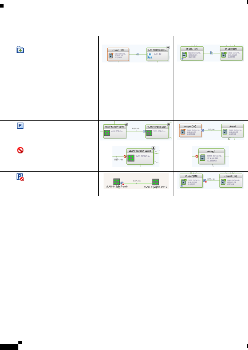
12-64
Cisco Prime Network 4.0 User Guide OL-29343-01
Chapter 12 Monitoring Carrier Ethernet Services
Working with VLANs
Viewing REP Properties for VLAN Service Links
To view REP properties for a VLAN service link, open the Link Properties window in either of the
following ways:
• Double-click the VLAN service link.
• Right-click the VLAN service link, and choose Properties.
Figure 12-34 shows an example of the Link Properties window with REP information.
Multiple links with badges
icon—Indicates that one or
more link is represented by
the visual link and at least
one of the links contains a
badge.
The multiple links icon is displayed
in the domain view if more than one
link is represented by the visual link
and at least one of the links contains
a badge.
The multiple links icon is displayed
in a VLAN overlay view if either of
the following is true:
• More than one link is
represented by the visual link
and the links have different
sources or destinations.
• A badge or REP identifier exists
on a sublink.
REP primary
badge—Indicates a REP
primary port.
Blocking badge—Indicates
a REP alternate port.
Primary and blocking
badge—Indicates a REP
primary port that is also
blocking.
Table 12-28 REP Icons and Badges in VLAN Domain Views and Overlays (continued)
Item Description VLAN Domain View VLAN Overlay
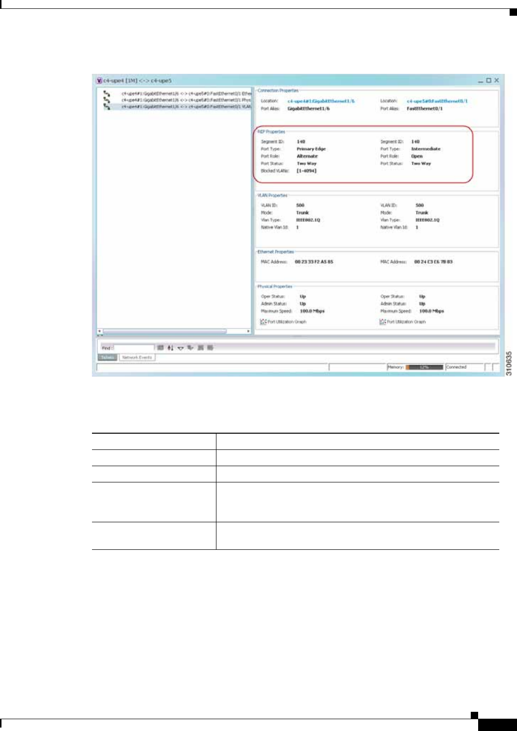
12-65
Cisco Prime Network 4.0 User Guide
OL-29343-01
Chapter 12 Monitoring Carrier Ethernet Services Working with VLANs
Figure 12-34 VLAN Service Link Properties Window with REP Information
Table 12-29 describes the information that is displayed for REP for each end of the link.
Table 12-29 REP Properties in VLAN Service Link Properties Window
Field Description
Segment ID REP segment identifier.
Port Type Port type: Primary Edge, Secondary Edge, or Intermediate.
Port Role Role or state of the REP port depending on its link status and
whether it is forwarding or blocking traffic: Failed, Alternate, or
Open.
Port Status Operational link state of the REP port: None, Init Down, No
Neighbor, One Way, Two Way, Flapping, Wait, or Unknown.
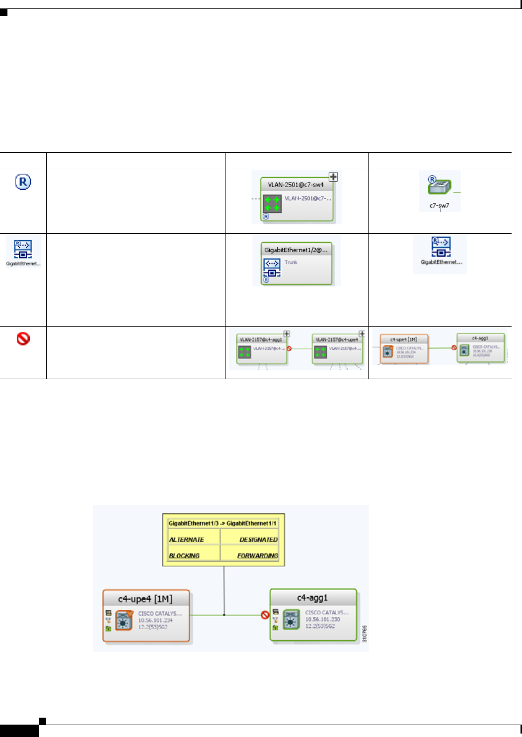
12-66
Cisco Prime Network 4.0 User Guide OL-29343-01
Chapter 12 Monitoring Carrier Ethernet Services
Working with VLANs
Viewing STP Information in VLAN Domain Views and VLAN Overlays
You can view STP segment and port information in Prime Network Vision in the map view. The icons
displayed depend on whether you view the STP information in the VLAN domain view or in a VLAN
overlay. Table 12-30 describes the icons and badges used to represent STP link and port information.
To view additional STP information in a VLAN overlay, right-click an STP link and choose Show
Callouts. The following STP port information is displayed as shown in Figure 12-35:
• Port name
• Port role
• Port state
Figure 12-35 STP Link Information in a VLAN Overlay
Table 12-30 STP Information in VLAN Domain Views and Overlays
Item Description VLAN Domain View VLAN Overlay
The STP root bridge, or root of the STP
tree, is indicated by an uppercase R.
An STP root port is the port at the root of
the STP tree. Each switching entity in the
network VLAN should have a port
designated as the root port.
The STP root port is indicated by an
uppercase R on the Ethernet flow point
that is designated the root port.
STP blocks some VLAN ports to ensure a
loop-free topology. The blocked port is
marked with a red deny badge on the side
on which traffic is denied.
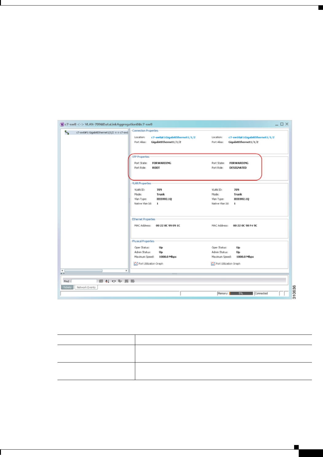
12-67
Cisco Prime Network 4.0 User Guide
OL-29343-01
Chapter 12 Monitoring Carrier Ethernet Services Working with VLANs
Viewing STP Properties for VLAN Service Links
To view STP properties for a VLAN service link, open the Link Properties window in one of the
following ways:
• Double-click the VLAN service link.
• Right-click the VLAN service link, and choose Properties.
Figure 12-36 shows an example of the Link Properties window with STP information.
Figure 12-36 STP Properties in VLAN Service Link Properties Window
Table 12-31 describes the information that is displayed for STP for the VLAN service link.
Table 12-31 STP Properties in VLAN Service Link Properties Window
Field Description
Port State STP port state: Disabled, Blocking, Listening, Learning, or
Forwarding,
Port Role STP port role: Unknown, Backup, Alternative, Designated, Root, or
Boundary.
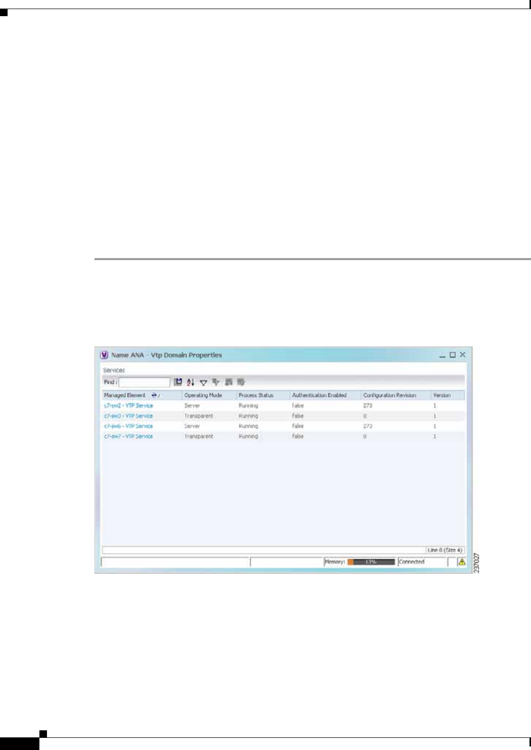
12-68
Cisco Prime Network 4.0 User Guide OL-29343-01
Chapter 12 Monitoring Carrier Ethernet Services
Working with VLANs
Viewing VLAN Trunk Group Properties
VTP is a Layer 2 multicast messaging protocol that manages the addition, deletion, and renaming of
VLANs on a switched network-wide basis.
Prime Network Vision displays VTP information in the logical inventory. VTP information is shown
only for Cisco devices that support VTP, and support is provided only for VTP Version 1 and 2. Support
for Version 3 is limited to the additional attributes that are supported by the version, such as primary and
secondary server. No support is provided for the display of VTP information at the port (trunk) level.
Prime Network Vision shows all VTP modes: Server, Client, Transparent, and Off. For each mode, Prime
Network Vision displays the relevant mode information such as VTP domain, VTP mode, VTP version,
VLAN trunks, and the trunk encapsulation. Prime Network Vision also displays VTP domain
information in a view that includes a list of all switches that are related to these domains, their roles
(server, client, and so on), and their VTP properties.
To view VTP properties:
Step 1 In Prime Network Vision, choose Network Inventory > VTP Domains.
Step 2 Double-click the VTP domain you want to view.
The VTP Domain Properties window is displayed as shown in Figure 12-37.
Figure 12-37 VTP Domain Properties Window in Logical Inventory

12-69
Cisco Prime Network 4.0 User Guide
OL-29343-01
Chapter 12 Monitoring Carrier Ethernet Services Working with VLANs
Table 12-32 describes the information that is displayed in the VTP Domain Properties window.
Step 3 To view the VTP properties at the device, double-click the VTP domain.
Table 12-33 describes the VTP information that is displayed in the inventory window content pane.
Table 12-32 VTP Domain Properties Window
Field Description
Managed Element Managed element name, hyperlinked to VTP in logical inventory.
Operating Mode VTP operating mode:
• Server—Allows VLAN creation, modification, and deletion, and
specification of other configuration parameters for the entire VTP
domain. Server is the default mode.
• Client—Same behavior as VTP server, except VLANs cannot be
created, changed, or deleted.
• Transparent—The device does not participate in the VTP. The
device does not advertise its VLAN configuration and does not
synchronize its VLAN configuration based on received
advertisements.
However, the device forwards received VTP advertisements out of
their trunk ports in VTP Version 2.
• Off—The device does not participate in VTP and does not forward
VTP advertisements.
Process Status Status of the VTP process: Running or Disabled.
Authentication Enabled Whether or not VTP authentication is enabled: True or False.
Authentication ensures authentication and integrity of switch-to-switch
VTP messages. VTP Version 3 introduces an additional mechanism to
authenticate the primary VTP server as the only device allowed to
change the VLAN configuration on a network-wide basis.
Configuration Revision 32-bit number that indicates the level of revision for a VTP packet.
Each VTP device tracks the VTP configuration revision number that is
assigned to it. Most VTP packets contain the VTP configuration revision
number of the sender.
Version VTP version: 1, 2, or 3.
Table 12-33 VTP Properties in Inventory
Field Description
Operating Mode VTP operating mode: Server, Client, Transparent, or Off.
Domain Name VTP domain name.
Version VTP version: 1, 2, or 3.
Pruning Whether or not VTP pruning is enabled: True or False.
VTP pruning increases available bandwidth by restricting flooded traffic
to those trunk links that the traffic must use to access the appropriate
network devices.
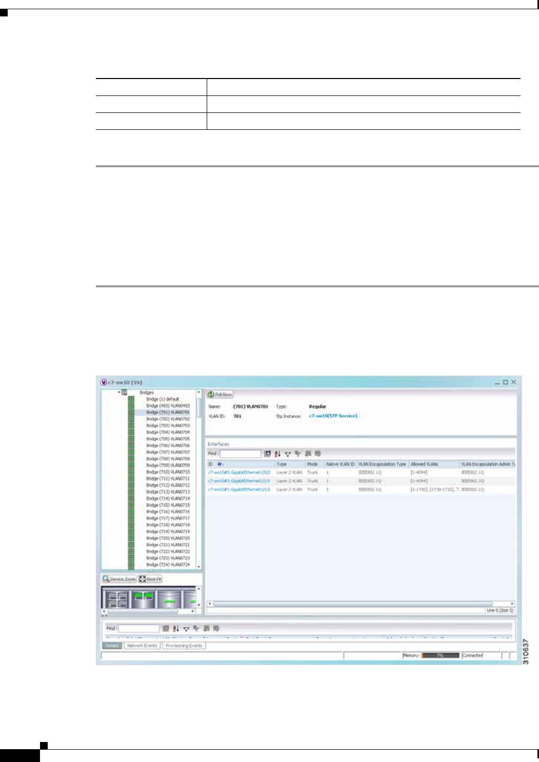
12-70
Cisco Prime Network 4.0 User Guide OL-29343-01
Chapter 12 Monitoring Carrier Ethernet Services
Working with VLANs
Step 4 When finished, press Ctrl + F4 to close each VTP properties window.
Viewing VLAN Bridge Properties
You can view VLAN bridges provisioned on a device by displaying the device in the Prime Network
Vision inventory window and choosing Bridges in logical inventory.
To view VLAN bridge properties:
Step 1 In Prime Network Vision, double-click the device containing the VLAN bridges you want to view.
Step 2 In the inventory window, choose Logical Inventory > Bridges > bridge.
VLAN bridge properties are displayed as shown in Figure 12-38.
Figure 12-38 VLAN Bridge Properties in Logical Inventory
Configuration Revision 32-bit number that indicates the level of revision for a VTP packet.
Authentication Whether or not VTP authentication is enabled: True or False.
Table 12-33 VTP Properties in Inventory (continued)
Field Description

12-71
Cisco Prime Network 4.0 User Guide
OL-29343-01
Chapter 12 Monitoring Carrier Ethernet Services Working with VLANs
Table 12-34 describes the information that is displayed. Depending on the bridge configuration, any of
the tabs might be displayed for the selected bridge.
Table 12-34 VLAN Bridge Properties
Field Description
Name VLAN bridge name.
Type VLAN bridge type.
MAC Address VLAN bridge MAC address.
VLAN ID VLAN bridge VLAN identifier.
STP Instance STP instance information, hyperlinked to the STP entry in logical
inventory.
Bridge Table Tab
MAC Address Bridge MAC address.
Port Port associated with the bridge, hyperlinked to the interface in physical
inventory.
Interfaces Tab
ID VLAN interface identifier, hyperlinked to the interface in physical
inventory.
Type VLAN interface type, such as Layer 2 VLAN.
Mode VLAN interface configuration mode:
• Unknown—The interface is not VLAN aware.
• Access—Puts the interface into permanent nontrunking mode and
negotiates to convert the link into a nontrunk link. The interface
becomes nontrunking.
• Dynamic Auto—The interface can convert the link to a trunk link. The
interface becomes a trunk if the neighbor interface is set to Trunk or
Dynamic Desirable mode.
• Dynamic Desirable—The interface actively attempts to convert the
link to a trunk link. The interface becomes a trunk if the neighboring
interface is set to Trunk, Dynamic Desirable, or Dynamic Auto mode.
Dynamic Desirable is the default mode for all Ethernet interfaces.
• Trunk—Puts the interface into permanent trunking mode and
negotiates to convert the link into a trunk link. The interface becomes
a trunk interface even if the neighbor interface is not a trunk interface.
• Dot1Q Tunnel—Configures the interface as a tunnel (nontrunking)
port to be connected in an asymmetric link with an 802.1Q trunk port.
802.1Q tunneling is used to maintain customer VLAN integrity across
a service provider network.
Native VLAN ID VLAN Identifier (VID) associated with this VLAN. The range of the
VLAN ID is 1 to 4067.
VLAN Encapsulation
Type Type of encapsulation configured on the VLAN, such as IEEE 802.1Q.

12-72
Cisco Prime Network 4.0 User Guide OL-29343-01
Chapter 12 Monitoring Carrier Ethernet Services
Working with VLANs
Step 3 When finished, press Ctrl + F4 to close each VLAN Bridge properties window.
Using Commands to Work With VLANs
The following commands can be launched from the physical inventory by right-clicking an Ethernet slot
and choosing Commands > Configuration. Before executing any commands, you can preview them
and view the results. If desired, you can also schedule the commands. To find out if a device supports
these commands, see the Cisco Prime Network 4.0 Supported Cisco VNEs.
Allowed VLANs List of the VLANs allowed on this VLAN interface.
VLAN Encapsulation
Admin Type VLAN administration encapsulation type, such as IEEE 802.1Q.
EFPs Tab
EFP ID EFP identifier.
Operational State EFP operational state.
VLAN VLAN identifier.
Inner VLAN CE-VLAN identifier.
Translated VLAN Translated VLAN identifier.
Translated Inner VLAN Translated CE-VLAN identifier.
Binding Port Hyperlinked entry to the port in physical inventory.
Description Brief description of the EFP.
Pseudowires Tab
ID Pseudowire identifier, hyperlinked to the VLAN entry in Bridges in logical
inventory.
Peer Identifier of the pseudowire peer, hyperlinked to the entry in the
Pseudowire Tunnel Edges table in logical inventory.
Tunnel ID Tunnel identifier.
Tunnel Status Status of the tunnel: Up or Down.
Peer Router IP IP address of the peer router for this pseudowire.
Sub Interfaces Tab
BER VLAN bit error rate.
Interface Name Interface on which the VLAN is configured.
VLAN Type Type of VLAN, such as Bridge or IEEE 802.1Q.
Operational State Subinterface operational state.
VLAN ID VLAN identifier.
Inner VLAN CE-VLAN identifier.
Table 12-34 VLAN Bridge Properties (continued)
Field Description

12-73
Cisco Prime Network 4.0 User Guide
OL-29343-01
Chapter 12 Monitoring Carrier Ethernet Services Understanding Unassociated Bridges
These commands are applicable only for Cisco ASR 5000 series network elements.
Note You might be prompted to enter your device access credentials while executing a command. Once you
have entered them, these credentials will be used for every subsequent execution of a command in the
same GUI client session. If you want to change the credentials, click Edit Credentials. The Edit
Credentials button will not be available for SNMP commands or if the command is scheduled for a later
time.
Understanding Unassociated Bridges
Some switching entities might not belong to a flow domain, such as a network VLAN, a VPLS instance,
or a network pseudowire. These switching entities are referred to as unassociated bridges.
In addition, a switching entity that belongs to a network VLAN is considered an unassociated bridge if
it meets both of the following criteria:
• The network VLAN contains a null Ethernet flow domain (EFD).
• The switching entity contains no switch ports.
Unassociated bridge switching entities can hold Ethernet flow points that serve as termination points on
different network VLANs. If these switching entities are added to a map with the relevant VLANs, the
links are displayed in the Prime Network Vision map.
Adding Unassociated Bridges
Prime Network Vision enables you to add unassociated bridges to maps and to view their properties.
To add an unassociated bridge to a map:
Step 1 In Prime Network Vision, select the required map or domain.
Step 2 Open the Add Unassociated Bridge dialog box in one of the following ways:
• Choose File Add to Map > Unassociated Bridge.
• In the toolbar, click Add to Map and choose Unassociated Bridge.
Figure 12-39 shows an example of the Add Unassociated Bridge dialog box.
Table 12-35 VLAN Commands
Command Inputs Required and Notes
Create VLAN VLAN ID, VLAN Context Name, Bind Interface Name, Status
Modify VLAN VLAN ID, Delete Bind Interface, Context Name, Bind Interface
Name, Status
Delete VLAN VLAN ID
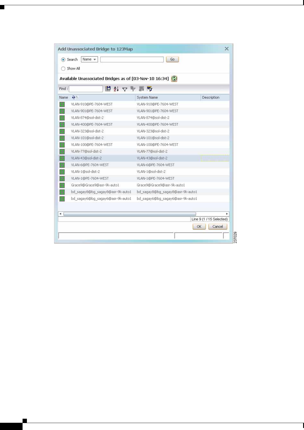
12-74
Cisco Prime Network 4.0 User Guide OL-29343-01
Chapter 12 Monitoring Carrier Ethernet Services
Understanding Unassociated Bridges
Figure 12-39 Add Unassociated Bridge Dialog Box
Step 3 In the Add Unassigned Bridge to domain dialog box, select the required bridge and click OK.
The map is refreshed and displays the newly added bridge as shown in Figure 12-40.
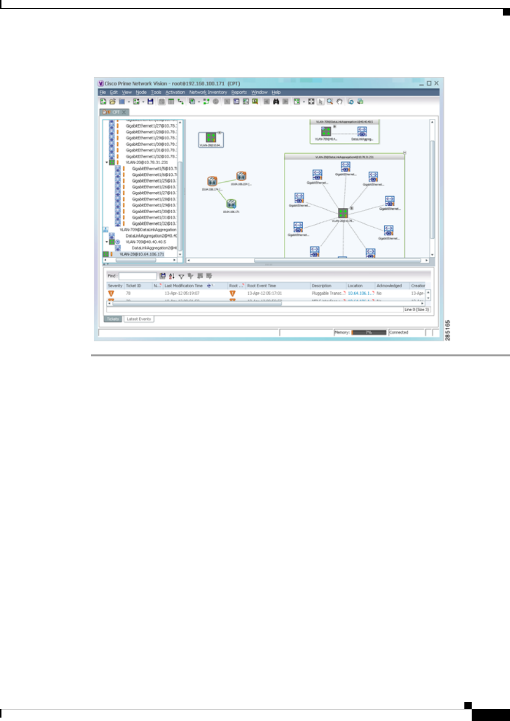
12-75
Cisco Prime Network 4.0 User Guide
OL-29343-01
Chapter 12 Monitoring Carrier Ethernet Services Working with Ethernet Flow Point Cross-Connects
Figure 12-40 Unassociated Bridge in Prime Network Vision
Working with Ethernet Flow Point Cross-Connects
Prime Network Vision automatically discovers Ethernet flow point (EFP) cross-connects, also known as
locally switched EFPs. Prime Network Vision also identifies changes in already identified EFP
cross-connects, such as cross-connect deletions or changes. Cross-connect changes can occur when one
side of the cross-connect is removed or replaced.
Prime Network Vision also associates the VLANs that contain the EFPs that are part of the
cross-connects. If the cross-connect contains a range EFP, which represents a range of VLANs, and you
add the related VLANs to a map, Prime Network Vision displays the links between them and the
cross-connect as well.
Prime Network Vision enables you to add EFP cross-connects to maps and to view their properties in
inventory, as described in the following topics:
• Adding EFP Cross-Connects, page 12-76
• Viewing EFP Cross-Connect Properties, page 12-76

12-76
Cisco Prime Network 4.0 User Guide OL-29343-01
Chapter 12 Monitoring Carrier Ethernet Services
Working with Ethernet Flow Point Cross-Connects
Adding EFP Cross-Connects
To add an EFP cross-connect to a map:
Step 1 In Prime Network Vision, select the map to which you wish to add the cross-connect.
Step 2 Open the Add EFP Cross-Connect dialog box in one of the following ways:
• Choose File Add to Map > Cross Connect.
• In the toolbar, click Add to Map and choose Cross Connect.
Step 3 In the Add EFP Cross Connect to domain dialog box, select the required EFP cross-connect and click
OK.
The map is refreshed and displays the newly added EFP cross-connect.
Viewing EFP Cross-Connect Properties
To view EFP cross-connect properties in Prime Network Vision, do either of the following:
• Select the EFP cross-connect with the properties you want to view, and choose Node > Properties.
• Double-click the device configured with an EFP cross-connect and, in the inventory window, choose
Logical Inventory > Local Switching > Local Switching Entity.
The information that is displayed for EFP cross-connects is the same in both the Local Switching Entry
Properties window and in the Local Switching Table in logical inventory (as shown in Figure 12-41).
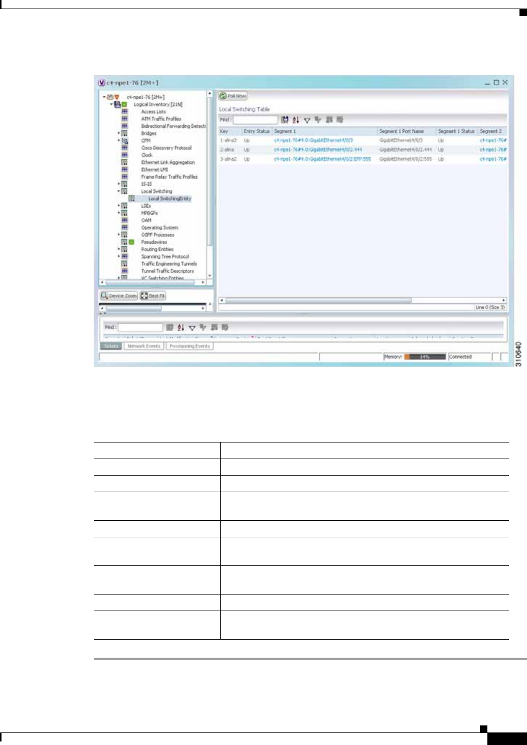
12-77
Cisco Prime Network 4.0 User Guide
OL-29343-01
Chapter 12 Monitoring Carrier Ethernet Services Working with Ethernet Flow Point Cross-Connects
Figure 12-41 Local Switching Table in Logical Inventory
Table 12-36 describes the information displayed for the EFP cross-connects in the Local Switching
Table.
Table 12-36 EFP Cross-Connect Properties in Local Switching Table
Field Description
Key Entry key for the cross-connect group.
Entry Status Status of the cross-connect: Down, Unresolved, or Up.
Segment 1 Identifier of the first cross-connect segment, hyperlinked to the
relevant entry in physical inventory.
Segment 1 Port Name Identifier of the first cross-connect segment port.
Segment 1 Status Status of the first cross-connect segment, such as Admin Up, Admin
Down, Oper Down, or Up.
Segment 2 Identifier of the second cross-connect segment, hyperlinked to the
relevant entry in physical inventory.
Segment 2 Port Name Identifier of the second cross-connect segment port.
Segment 2 Status Status of the second cross-connect segment, such as Admin Up,
Admin Down, Oper Down, or Up.

12-78
Cisco Prime Network 4.0 User Guide OL-29343-01
Chapter 12 Monitoring Carrier Ethernet Services
Working with VPLS and H-VPLS Instances
Working with VPLS and H-VPLS Instances
Virtual Private LAN Service (VPLS) is a Layer 2 VPN technology that provides Ethernet-based
multipoint-to-multipoint communication over MPLS networks. VPLS allows geographically dispersed
sites to share an Ethernet broadcast domain by connecting sites through pseudowires. The network
emulates a LAN switch or bridge by connecting customer LAN segments to create a single bridged
Ethernet LAN.
Hierarchical VPLS (H-VPLS) partitions the network into several edge domains that are interconnected
using an MPLS core. The edge devices learn only of their local N-PE devices and therefore do not need
large routing table support. The H-VPLS architecture provides a flexible architectural model that enables
Ethernet multipoint and point-to-point Layer 2 VPN services, as well as Ethernet access to Layer 3 VPN
services, enabling service providers to offer multiple services across a single high-speed architecture.
Prime Network Vision discovers the following VPLS-related information from the network and
constructs VPLS instances:
• VSIs
• Pseudowires
• EFPs
• Switching entities
Prime Network Vision enables you to:
• Add VPLS instances to a map—See Adding VPLS Instances to a Map, page 12-79.
• Apply VPLS overlays—See Applying VPLS Instance Overlays, page 12-80.
• View link details in VPLS overlays—See Viewing Pseudowire Tunnel Links in VPLS Overlays,
page 12-82.
• View VPLS-related properties—See the following topics:
–
Viewing VPLS Instance Properties, page 12-84
–
Viewing Virtual Switching Instance Properties, page 12-85
–
Viewing VPLS Core or Access Pseudowire Endpoint Properties, page 12-87
–
Viewing VPLS Access Ethernet Flow Point Properties, page 12-89
You can delete a VPLS forward from Prime Network Vision if it is displayed with the reconciliation icon.

12-79
Cisco Prime Network 4.0 User Guide
OL-29343-01
Chapter 12 Monitoring Carrier Ethernet Services Working with VPLS and H-VPLS Instances
Adding VPLS Instances to a Map
You can add the VPLS instances that Prime Network Vision discovers to maps as required.
To add a VPLS instance to a map:
Step 1 In Prime Network Vision, select the required map or domain.
Step 2 Open the Add VPLS Instance to map dialog box in either of the following ways:
• In the toolbar, choose Add to Map > VPLS.
• In the menu bar, choose File > Add to Map > VPLS.
Step 3 In the Add VPLS Instance dialog box, do either of the following:
• To search for specific elements:
a. Choose Search.
b. To narrow the display to a range of VPLS instances or a group of VPLS instances, enter a search
string in the search field.
c. Click Go.
For example, if you enter VPLS1, the VPLS instances that have names containing the string VPLS1
are displayed.
• To view all available VPLS instances, choose Show All and click Go.
The VPLS instances that meet the specified search criteria are displayed in the Add VPLS Instance
dialog box in table format. The dialog box also displays the date and time at which the list was generated.
To update the list, click Refresh.
Note If an element is not included in your scope, it is displayed with the locked device icon.
For information about sorting and filtering the table contents, see Filtering and Sorting Tabular Content,
page 2-42.
Step 4 In the Add VPLS Instance dialog box, select the instances that you want to add. You can select and add
multiple instances by pressing Ctrl while selecting individual instances or by pressing Ctrl +Shift to
select a group of instances.
Step 5 Click OK.
The VPLS instance is displayed in the navigation pane and in the content area. In addition, any
associated tickets are displayed in the ticket pane. See Figure 12-42.
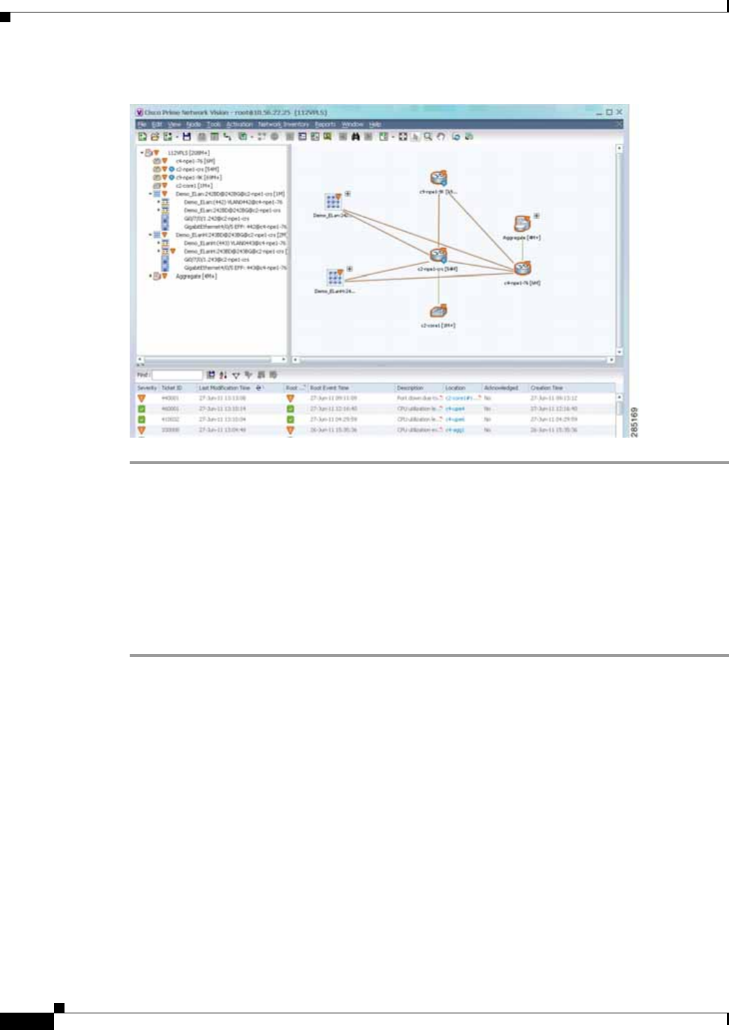
12-80
Cisco Prime Network 4.0 User Guide OL-29343-01
Chapter 12 Monitoring Carrier Ethernet Services
Working with VPLS and H-VPLS Instances
Figure 12-42 VPLS Instance in Prime Network Vision Map
The VPLS instance information is saved with the map in the Prime Network database.
Applying VPLS Instance Overlays
An VPLS instance overlay allows you to isolate the parts of a network that are being used by a specific VPLS
instance.
To apply a VPLS instance overlay:
Step 1 In Prime Network Vision, choose the map in which you want to apply an overlay.
Step 2 From the toolbar, choose Choose Overlay Type > VPLS.
Figure 12-43 shows an example of the Select VPLS Instance Overlay for map dialog box.
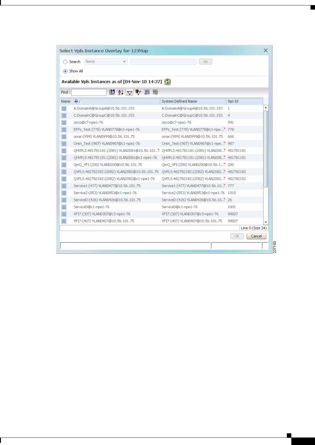
12-81
Cisco Prime Network 4.0 User Guide
OL-29343-01
Chapter 12 Monitoring Carrier Ethernet Services Working with VPLS and H-VPLS Instances
Figure 12-43 Select VPLS Instance Overlay Dialog Box
Step 3 Select the required VPLS instance for the overlay.
Step 4 Click OK.
The elements being used by the selected VPLS instance are highlighted in the map while the other
elements are dimmed, as shown in Figure 12-44.
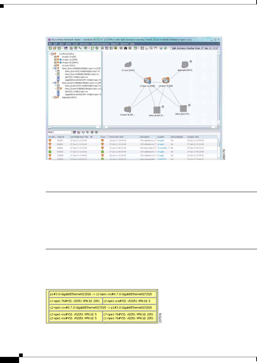
12-82
Cisco Prime Network 4.0 User Guide OL-29343-01
Chapter 12 Monitoring Carrier Ethernet Services
Working with VPLS and H-VPLS Instances
Figure 12-44 VPLS Instance Overlay in Prime Network Vision
Step 5 To hide and view the overlay, click Hide Overlay/Show Overlay in the toolbar. The button toggles
depending on whether the overlay is currently displayed or hidden.
Step 6 To remove the overlay, choose Choose Overlay Type > None.
Viewing Pseudowire Tunnel Links in VPLS Overlays
When a VPLS overlay is applied to a map in Prime Network Vision, you can view the details of the
pseudowires that are interconnected through selected links.
To view unidirectional or bidirectional pseudowire traffic links when a VPLS overlay is applied to a map:
Step 1 Right-click the required link in the overlay, and choose Show Callouts. The link must be visible (not
dimmed) in the map.
Link information is displayed as shown in Figure 12-45.
Figure 12-45 Link Callout Window for a VPLS Overlay
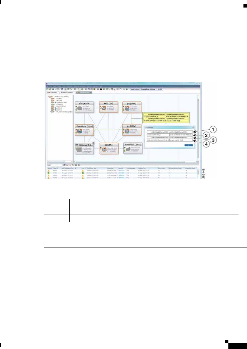
12-83
Cisco Prime Network 4.0 User Guide
OL-29343-01
Chapter 12 Monitoring Carrier Ethernet Services Working with VPLS and H-VPLS Instances
The callout window displays the following information for each link represented by the selected link:
• Link details and direction.
• Details of the sites using the link and the interlinks.
Step 2 To view the pseudowire link details, double-click the yellow callout window.
The details about the link are displayed in the Link Details window as shown in Figure 12-46.
Figure 12-46 Link Details Window for a VPLS Overlay
The Link Details window provides the following information:
Step 3 Click OK to close the Link Details window.
Step 4 To close the link callout window, right-click the selected link, then choose Hide Callouts.
Viewing VPLS-Related Properties
Prime Network Vision enables you to view the properties of the following VPLS-related elements:
• VPLS instances—See Viewing VPLS Instance Properties, page 12-84.
• Virtual Switching Instances—Viewing Virtual Switching Instance Properties, page 12-85
• Tunnels—See Viewing VPLS Core or Access Pseudowire Endpoint Properties, page 12-87.
• Port connectors—See Viewing VPLS Access Ethernet Flow Point Properties, page 12-89.
1Link details and direction. In this example, the link is from p1 to p2.
3Link details and direction. In this example, the link is from p2 to p1.
2 and 4 Details of the pseudowire tunnel traversing this link.
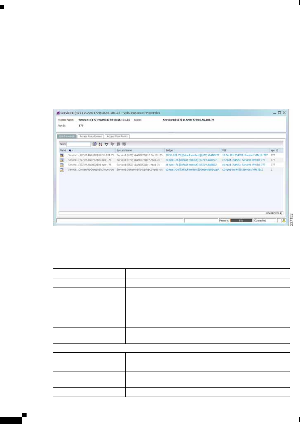
12-84
Cisco Prime Network 4.0 User Guide OL-29343-01
Chapter 12 Monitoring Carrier Ethernet Services
Working with VPLS and H-VPLS Instances
Viewing VPLS Instance Properties
To view the properties of a VPLS instance in Prime Network Vision, open the VPLS Instance Properties
window in either of the following ways:
• In the navigation pane or the map pane, right-click the VPLS instance and choose Properties.
• In the navigation pane or the map pane, select the VPLS instance and choose Node > Properties.
Figure 12-47 shows an example of the VPLS Instance Properties window.
Figure 12-47 VPLS Instance Properties Window
Table 12-37 describes the information that is displayed for VPLS instance properties.
The tabs that appear in the window depend on the VPLS instance and its configuration.
Table 12-37 VPLS Instance Properties
Field Description
System Name Name that Prime Network Vision assigns to the VPLS instance.
Name User-defined name of the VPLS instance.
When the VPLS instance is created, the system name and this name
are the same. If you change the name of the VPLS instance
(right-click, then choose Rename), the changed name appears in
this field whereas the system name retains the original name.
VPN ID VPN identifier used in an MPLS network to distinguish between
different VPLS traffic.
VPLS Forwards Tab
Name User-defined name of the VPLS forward.
System Name Name that Prime Network Vision assigns to the VPLS forward.
Bridge Bridge that the VSI is configured to use, hyperlinked to the bridge
table in logical inventory.
VSI VSI hyperlinked to the relevant entry in logical inventory.

12-85
Cisco Prime Network 4.0 User Guide
OL-29343-01
Chapter 12 Monitoring Carrier Ethernet Services Working with VPLS and H-VPLS Instances
Viewing Virtual Switching Instance Properties
To view VSI properties in Prime Network Vision, open the VSI properties window in either of the
following ways:
• Double-click the required device and, in the inventory window, choose Logical
Inventory > VSIs > vsi.
• In the navigation pane, expand the VPLS instance, right-click the required VPLS forward, and
choose Inventory or Properties. (See Figure 12-48.)
VPN ID VPN identifier for the VSI.
Access Pseudowires Tab
Name Pseudowire name.
Port VSI on which the pseudowire is configured, hyperlinked to the entry
in logical inventory.
Local Router IP Local router IP address on which the pseudowire is configured.
Tunnel ID Virtual circuit identifier of the pseudowire.
PTP Tunnel Hyperlinked entry to the pseudowire properties in logical inventory.
Peer Router IP Peer router IP address on which the pseudowire is configured.
Peer OID Hyperlinked entry to the pseudowire properties of the peer.
Pseudowire Type Type of pseudowire, such as Ethernet, Ethernet Tagged, CESoPSN
Basic, PPP, or SAToP.
Pseudowire Edge Binding
Type Pseudowire endpoint association:
• 0—Unknown
• 1—Connection termination point
• 2—Ethernet flow point
• 3—Switching entity
• 4—Pseudowire switching entity
• 5—VPLS forward
Access Flow Points Tab
Name Access flow point name. Double-click to view port connector
properties.
Port Interface configured as a flow point, hyperlinked to the interface in
physical inventory.
Table 12-37 VPLS Instance Properties (continued)
Field Description
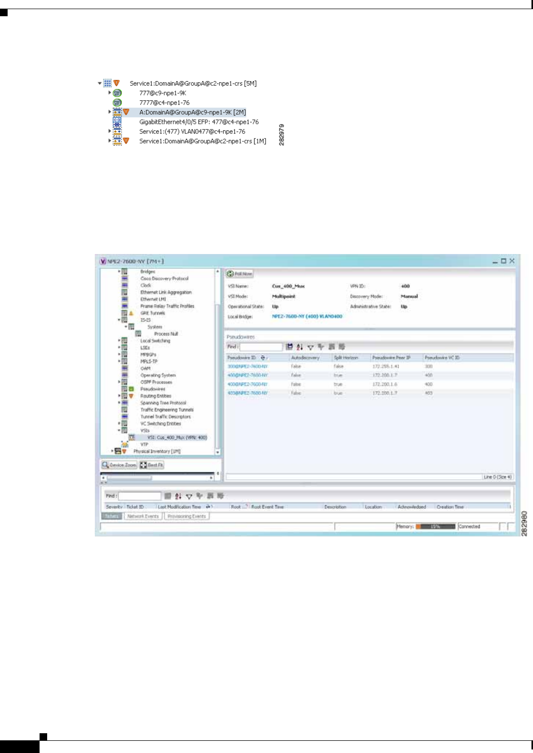
12-86
Cisco Prime Network 4.0 User Guide OL-29343-01
Chapter 12 Monitoring Carrier Ethernet Services
Working with VPLS and H-VPLS Instances
Figure 12-48 VPLS Forward in Prime Network Vision Navigation Pane
If you right-click the VPLS forward and choose Inventory, the inventory window is displayed. If you
right-click the VPLS forward and choose Properties, the VSI Properties window is displayed. The
information displayed is the same for both options.
VSI properties are displayed as shown in Figure 12-49.
Figure 12-49 VSI Properties in Logical Inventory

12-87
Cisco Prime Network 4.0 User Guide
OL-29343-01
Chapter 12 Monitoring Carrier Ethernet Services Working with VPLS and H-VPLS Instances
Table 12-38 describes the information that is displayed for the selected VSI.
Viewing VPLS Core or Access Pseudowire Endpoint Properties
Pseudowire endpoints are displayed under VPLS Instance (Access) or VPLS Forward (Core) in the
Prime Network Vision navigation pane.
To view pseudowire endpoint properties for a VPLS instance, right-click the required pseudowire
endpoint in the navigation pane, and choose Properties. (See Figure 12-50.)
Figure 12-50 VPLS Pseudowire in Prime Network Vision Navigation Pane
Figure 12-51 shows an example of the Tunnel Properties window that is displayed.
Table 12-38 VSI Properties in Logical Inventory
Field Description
VSI Name VSI name.
VPN ID VPN identifier used in an MPLS network to distinguish between different
VPLS traffic.
VSI Mode VSI mode: Point-to-Point (default) or Multipoint.
Discovery Mode VSI discovery mode: Manual, BGP, LDP, RADIUS, DNS, MSS/OSS, or
Unknown.
Operational State VSI operational status: Up or Down.
Administrative State VSI administrative status: Up or Down.
Local Bridge Local bridge, hyperlinked to the bridge in logical inventory.
Pseudowires Table
Pseudowire ID Pseudowire identifier, hyperlinked to the Tunnel Edges table under
Pseudowires in logical inventory.
Autodiscovery Whether the pseudowire was automatically discovered: True or False.
Split Horizon SSH pseudowire policy that indicates whether or not packets are forwarded
to the MPLS core: True or False.
Pseudowire Peer IP IP address of the pseudowire peer.
Pseudowire VC ID Pseudowire virtual circuit identifier.
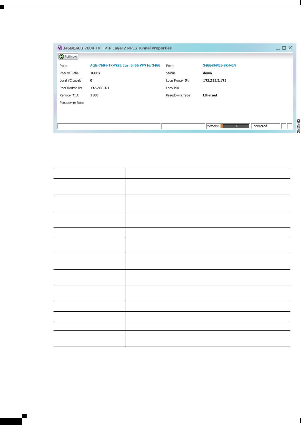
12-88
Cisco Prime Network 4.0 User Guide OL-29343-01
Chapter 12 Monitoring Carrier Ethernet Services
Working with VPLS and H-VPLS Instances
Figure 12-51 VPLS Tunnel Properties Window
Table 12-39 describes the information that is displayed for pseudowire endpoint properties.
Table 12-39 Tunnel Properties Window
Field Description
Port VSI on which the pseudowire is configured, hyperlinked to the VSI
in logical inventory.
Peer Hyperlinked entry to the pseudowire endpoint peer pseudowires in
logical inventory.
Peer VC Label MPLS label that is used by this router to identify or access the tunnel.
It is inserted into the MPLS label stack by the peer router.
Tunnel Status Operational state of the tunnel: Up or Down.
Local VC Label MPLS label that is used to identify or access the tunnel. It is inserted
into the MPLS label stack by the local router.
Local Router IP IP address of this tunnel edge, which is used as the MPLS router
identifier.
Tunnel ID Identifier that, along with the router IP addresses of the two pseudowire
endpoints, identifies the PWE3 tunnel.
Peer Router IP IP address of the peer tunnel edge, which is used as the MPLS router
identifier.
Local MTU Size, in bytes, of the MTU on the local interface.
Remote MTU Size, in bytes, of the MTU on the remote interface.
Signaling Protocol Protocol used by MPLS to build the tunnel, such as LDP or TDP.
Pseudowire Type Type of pseudowire, such as Ethernet, Ethernet Tagged, CESoPSN
Basic, PPP, or SAToP.
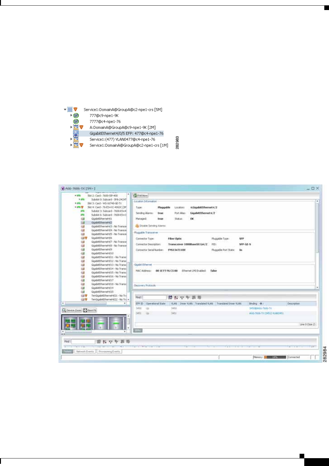
12-89
Cisco Prime Network 4.0 User Guide
OL-29343-01
Chapter 12 Monitoring Carrier Ethernet Services Working with VPLS and H-VPLS Instances
Viewing VPLS Access Ethernet Flow Point Properties
The ports that represent the attachment circuits to VPLS instances are displayed under VPLS instances
in the Prime Network Vision navigation pane.
To view the properties for the Access Ethernet Flow Points configured for a VPLS instance, right-click
the required interface in the navigation pane, and choose Inventory. (See Figure 12-52.)
Figure 12-52 VPLS Interface in Prime Network Vision Navigation Pane
Figure 12-53 shows an example of the information displayed for the interface in physical inventory.
Figure 12-53 EFP Properties in Physical Inventory
The information displayed in this window is the same as that displayed when the interface is selected in
physical inventory.
The following information is displayed, depending on the interface and its configuration:
• Location and interface details.
• Technology-related information, such as Ethernet CSMA/CD or ATM IMA properties.
• VLAN configuration details.

12-90
Cisco Prime Network 4.0 User Guide OL-29343-01
Chapter 12 Monitoring Carrier Ethernet Services
Working with Pseudowires
• List of the configured subinterfaces on the port. For more information on the Subinterfaces table,
see Viewing a Port Configuration, page 3-25.
• List of the configured EFPs on the port. For more information on the EFPs table, see Viewing EFP
Properties, page 12-33.
• List of VLAN mappings configured on the port. For more information about the VLAN Mappings
table, see Viewing VLAN Mappings, page 12-53.
Working with Pseudowires
Prime Network supports the discovery and modeling of Any Transport over MPLS (AToM) and Ethernet
over MPLS (EoMPLS) domains that span multisegment pseudowires. After discovery is complete, you
can add any of the pseudowires to a map, view their properties in logical inventory, or view their
redundancy status.
You can run the psuedowire commands on all Cisco IOS and Cisco IOS XR devices that support
pseudowire technology, such as
• Cisco 7200 series routers
• Cisco 7600 series routers
• Cisco ASR 9000 series aggregation services routers
• Cisco XR 12000 series routers
• Cisco ME 3600X and Cisco ME 3800X Carrier Ethernet Switches
• Cisco Carrier Packet Transport (CPT) System
For details on the software versions Prime Network supports for these network elements, see the Cisco
Prime Network 4.0 Supported Cisco VNEs. To run the pseudowire commands, the software on the
network element must support the pseudowire technology.
The following topics describe the options available to you for working with pseudowires in Prime
Network:
• Adding Pseudowires to a Map, page 12-90
• Viewing Pseudowire Properties, page 12-93
• Displaying Pseudowire Information, page 12-95
• Viewing Pseudowire Redundancy Service Properties, page 12-96
• Applying Pseudowire Overlays, page 12-98
• Monitoring the Pseudowire Headend, page 12-100
Adding Pseudowires to a Map
You can add a pseudowire that Prime Network discovers to maps as required.
To add a pseudowire to a map:
Step 1 In Prime Network Vision, select the required map or domain.
Step 2 Open the Add Pseudowire to map dialog box in either of the following ways:
• In the toolbar, choose Add to Map > Pseudowire.

12-91
Cisco Prime Network 4.0 User Guide
OL-29343-01
Chapter 12 Monitoring Carrier Ethernet Services Working with Pseudowires
• In the menu bar, choose File > Add to Map > Pseudowire.
Figure 12-54 shows an example of the Add Pseudowire dialog box.
Figure 12-54 Add Pseudowire Dialog Box
Step 3 In the Add Pseudowire dialog box, do either of the following:
• To search for specific elements:
a. Choose Search.
b. To narrow the display to a range of pseudowire or a group of pseudowires, enter a search string
in the search field.
c. Click Go.
For example, if you enter pseudo1, the pseudowires that have names containing the string “pseudo1”
are displayed.
• To view all available pseudowires, choose Show All and click Go.
The pseudowires that meet the specified search criteria are displayed in the Add Pseudowire dialog box
in table format. The dialog box also displays the date and time at which the list was generated. To update
the list, click Refresh.
Note If an element is not included in your scope, it is displayed with the locked device icon.
For information about sorting and filtering the table contents, see Filtering and Sorting Tabular Content,
page 2-42.
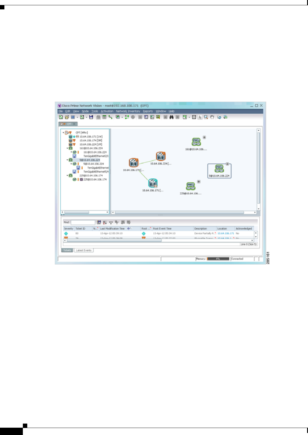
12-92
Cisco Prime Network 4.0 User Guide OL-29343-01
Chapter 12 Monitoring Carrier Ethernet Services
Working with Pseudowires
Step 4 In the Add Pseudowire dialog box, select the pseudowires that you want to add. You can select and add
multiple pseudowires by pressing Ctrl while selecting individual pseudowires or by pressing
Ctrl +Shift to select a group of pseudowires.
Step 5 Click OK.
The pseudowire is displayed in the navigation pane and in the content area. In addition, any associated
tickets are displayed in the ticket pane. See Figure 12-55.
Figure 12-55 Pseudowire in Prime Network Vision Map
Step 6 Click the pseudowire in the navigation pane or double-click the pseudowire in the map pane to view the
pseudowire components, such as pseudowire endpoints, pseudowire switching entities, and terminating
interfaces.
Figure 12-56 shows an example of an expanded pseudowire in Prime Network Vision.

12-93
Cisco Prime Network 4.0 User Guide
OL-29343-01
Chapter 12 Monitoring Carrier Ethernet Services Working with Pseudowires
Figure 12-56 Pseudowire Components in Prime Network Vision Maps
The pseudowire information is saved with the map in the Prime Network database.
Viewing Pseudowire Properties
To view pseudowire properties:
Step 1 In Prime Network Vision, select the required map or domain.
Step 2 To view pseudowire endpoint properties configured on an element:
a. In the navigation or map pane, right-click the required element and then choose Inventory.
b. In the inventory window, choose Logical Inventory > Pseudowires.
The Tunnel Edges table is displayed, listing the pseudowire endpoints configured on the selected
element. For a description of the information contained in the Pseudowires Tunnel Edges table, see
Table 18-27.
Step 3 To view the properties of a pseudowire that you added to a map, do either of the following:
• If the pseudowire icon is of the largest size, click the Properties button.
• Right-click the element, and then choose Properties.
The Pseudowire Properties window is displayed as shown in Figure 12-57.

12-94
Cisco Prime Network 4.0 User Guide OL-29343-01
Chapter 12 Monitoring Carrier Ethernet Services
Working with Pseudowires
Figure 12-57 Pseudowire Properties Window
Table 12-40 describes the information presented in the Pseudowire Properties window.
Step 4 To view the properties of a pseudowire endpoint associated with a pseudowire, right-click the required
pseudowire endpoint, and then choose Properties.
The Tunnel Properties window containing the pseudowire endpoint properties is displayed as shown in
Figure 12-51 and described in Table 12-39.
Step 5 To view the properties of a pseudowire switching entity associated with the pseudowire, select the
switching entity, and then choose Node > Inventory.
The Local Switching table is displayed as shown in Figure 12-41.
Table 12-36 describes the information displayed in the Local Switching table.
Step 6 To view the properties of the pseudowire endpoint that terminates on the subinterface, right-click the
required interface, and then choose Properties.
Note The selected port must be an Ethernet subinterface for the Contained Current CTPs table to be
displayed.
Table 12-41 describes the information displayed in the Contained Current CTPs table.
Table 12-40 Pseudowire Properties Window
Field Description
Name Name of the pseudowire.
Multisegment Pseudowire Whether or not the pseudowire is multisegment: True or False.
System Name Internal or system-generated name of the pseudowire.
Pseudowire Type Type of pseudowire, such as Ethernet, Ethernet Tagged, CESoPSN
Basic, PPP, or SAToP.

12-95
Cisco Prime Network 4.0 User Guide
OL-29343-01
Chapter 12 Monitoring Carrier Ethernet Services Working with Pseudowires
Step 7 To view the properties of an Ethernet flow point associated with the pseudowire, right-click the EFP and
then choose Properties.
See Viewing EFP Properties, page 12-33 for the information that is displayed for EFPs.
Displaying Pseudowire Information
Note You might be prompted to enter your device access credentials while exectuing the command. Once you
have entered them, these credentials will be used for every subsequent execution of a command in the
same GUI client session. If you want to change the credentials, click Edit Credentials. The Edit
Credentials button will not be available for SNMP commands or if the command is scheduled for a later
time.
To To view Virtual Circuit Connectivity Verification (VCCV) and Control Channel (CC) information for
a pseudowire endpoint:
Table 12-41 Contained Current CTPs Table
Field Description
Local Interface The name of the subinterface or port, hyperlinked to the interface in
physical inventory.
ID The tunnel identifier, hyperlinked to Pseudowires Tunnel Edges
table in logical inventory.
Peer The peer tunnel identifier, hyperlinked to the peer pseudowire
tunnel in logical inventory.
Tunnel ID The identifier that, along with the router IP addresses of the two
tunnel edges, identifies the tunnel.
Tunnel Status The operational state of the tunnel: Up or Down.
Local Router IP The IP address of this tunnel edge, which is used as the router
identifier.
Peer Router IP The IP address of the peer tunnel edge, which is used as the router
identifier.
Pseudowire Type Type of pseudowire, such as Ethernet, Ethernet Tagged, CESoPSN
Basic, PPP, or SAToP.
Local MTU The size, in bytes, of the MTU on the local interface.
Remote MTU The size, in bytes, of the MTU on the remote interface.
Local VC Label The MPLS label that is used by this router to identify or access the
tunnel. It is inserted in the MPLS label stack by the local router.
Peer VC Label The MPLS label that is used by this router to identify or access the
tunnel. It is inserted in the MPLS label stack by the peer router.
Signaling Protocol The protocol used to build the tunnel, such as LDP or TDP.
Preferred Path Tunnel The path to be used for pseudowire traffic.

12-96
Cisco Prime Network 4.0 User Guide OL-29343-01
Chapter 12 Monitoring Carrier Ethernet Services
Working with Pseudowires
Step 1 In the require map, double-click the required device configured for pseudowire.
Step 2 In the inventory window, choose Logical Inventory > Pseudowire.
Step 3 In the Tunnel Edges table, right-click the required interface and choose Commands > Show > Display
Pseudowire.
Step 4 In the Display Pseudowire dialog box, do either of the following:
• To view the command before running it, click Preview.
• To run the command, click Execute.
When you click Execute, the results are displayed in the dialog box.
Step 5 The following information is displayed:
• The element name.
• The command issued.
• The results, including:
–
VCCV: CC Type—The types of CC processing that are supported. The number indicates the
position of the bit that was set in the received octet. The available values are:
- CW [1]—Control Word
- RA [2]—Router Alert
- TTL [3]—Time to Live
- Unkn [x]—Unknown
–
Elapsed time—The elapsed time, in seconds.
Step 6 Click Close to close the Display Pseudowire dialog box.
Viewing Pseudowire Redundancy Service Properties
If a pseudowire is configured for redundancy service, a redundancy service badge is applied to the
secondary (backup) pseudowire in the navigation and map panes in the Prime Network Vision window.
Additional redundancy service details are provided in the inventory window for the device on which the
pseudowire is configured.
To view redundancy service properties for pseudowires:
Step 1 To determine if a pseudowire is configured for redundancy service, expand the required pseudowire in
the navigation or map pane.
If the pseudowire is configured for redundancy service, the redundancy service badge appears in the
navigation and map panes as shown in Figure 12-58.
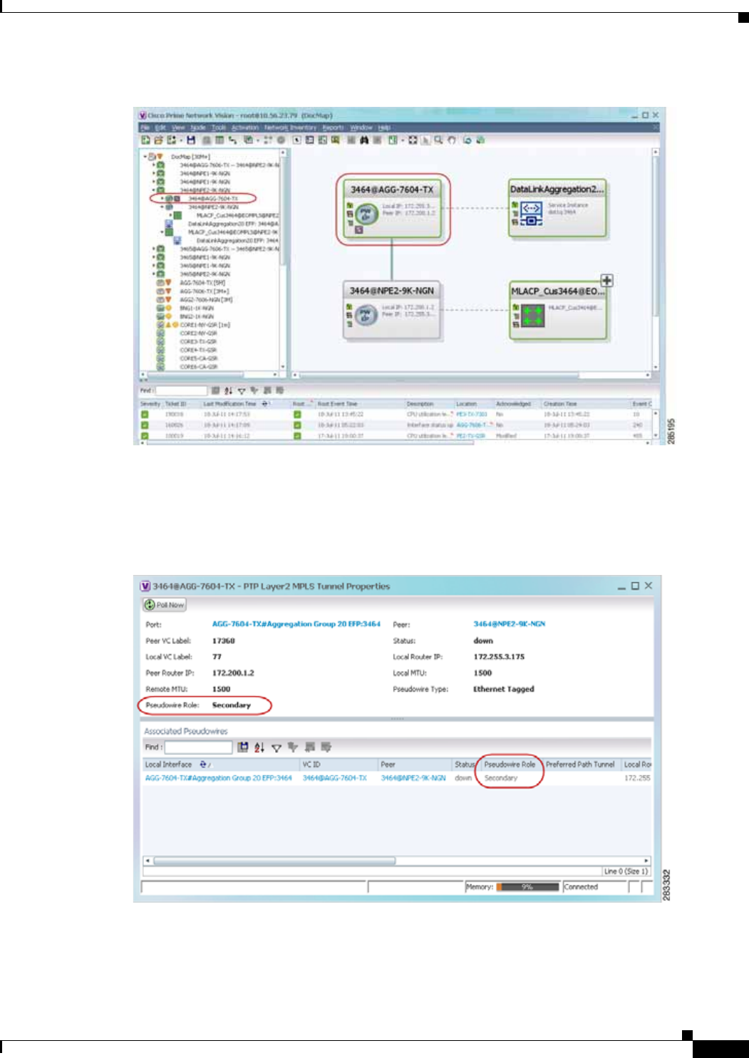
12-97
Cisco Prime Network 4.0 User Guide
OL-29343-01
Chapter 12 Monitoring Carrier Ethernet Services Working with Pseudowires
Figure 12-58 Pseudowire Redundancy Service Badge in a Map
Step 2 To view additional details, in the map, double-click the element with the redundancy service badge.
The PTP Layer 2 MPLS Tunnel Properties window is displayed as shown in Figure 12-59 and shows that
the selected pseudowire has a Secondary role in a redundancy service.
Figure 12-59 Layer 2 MPLS Tunnel Properties for Pseudowire Redundancy Service
Step 3 In the PTP Layer 2 MPLS Tunnel Properties window, click the VC ID hyperlink.
The Tunnel Edges table in logical inventory is displayed, with the local interface selected in the table.
(See Figure 12-60.)
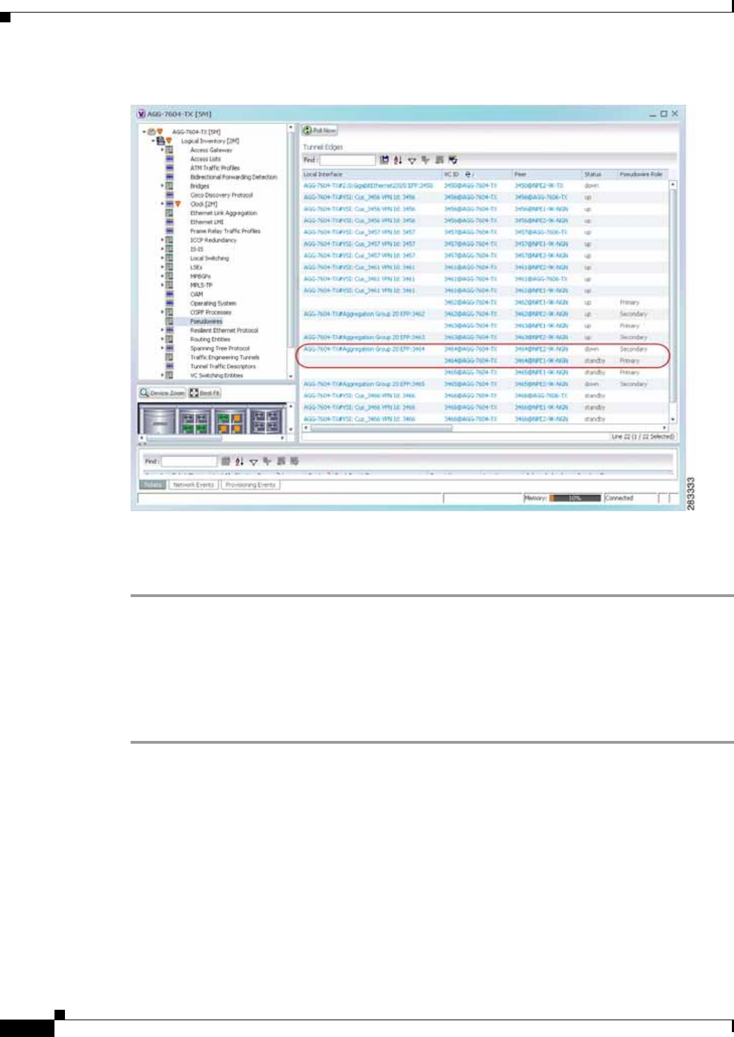
12-98
Cisco Prime Network 4.0 User Guide OL-29343-01
Chapter 12 Monitoring Carrier Ethernet Services
Working with Pseudowires
Figure 12-60 Pseudowire Redundancy Service in Logical Inventory
The entries indicate that the selected tunnel edge has a Secondary role in the first VC and a Primary role
in the second VC.
For more information about the Pseudowires Tunnel Edges table, see Table 18-27.
Applying Pseudowire Overlays
A pseudowire overlay allows you to isolate the parts of a network that are used by a specific pseudowire.
To apply a pseudowire overlay:
Step 1 In Prime Network Vision, choose the map in which you want to apply an overlay.
Step 2 From the toolbar, choose Choose Overlay Type > Pseudowire.
Figure 12-61 shows an example of the Select Pseudowire Overlay for map dialog box.
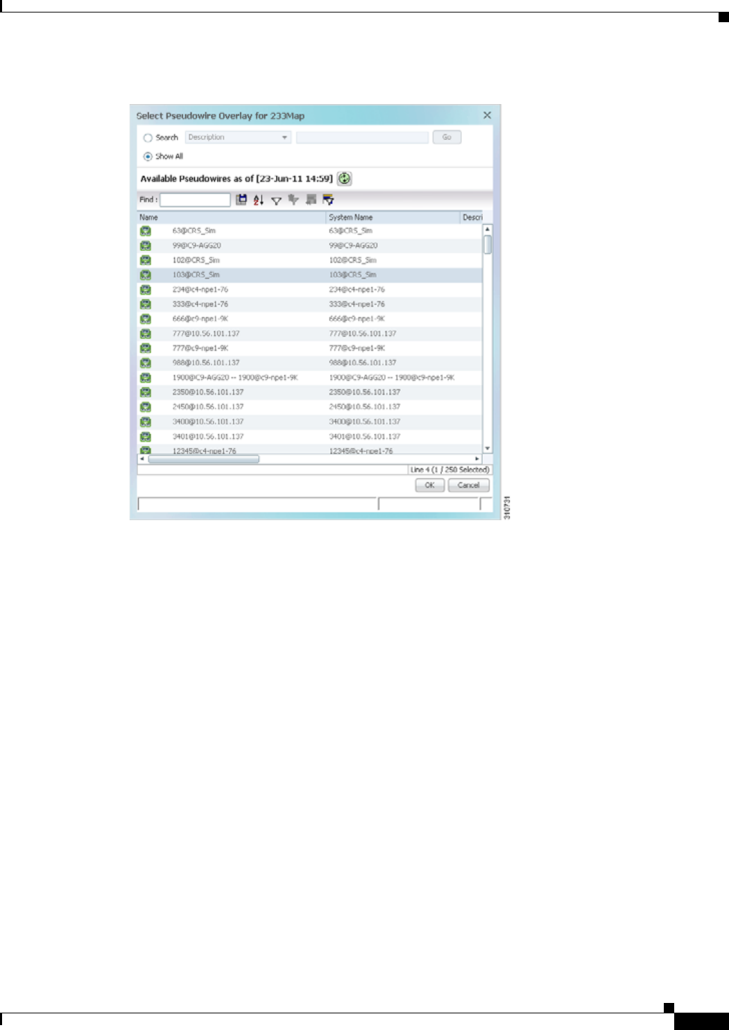
12-99
Cisco Prime Network 4.0 User Guide
OL-29343-01
Chapter 12 Monitoring Carrier Ethernet Services Working with Pseudowires
Figure 12-61 Select Pseudowire Overlay Dialog Box
Step 3 Select the required pseudowire for the overlay.
Step 4 Click OK.
The elements being used by the selected pseudowire are highlighted in the map while the other elements
are dimmed, as shown in Figure 12-62.
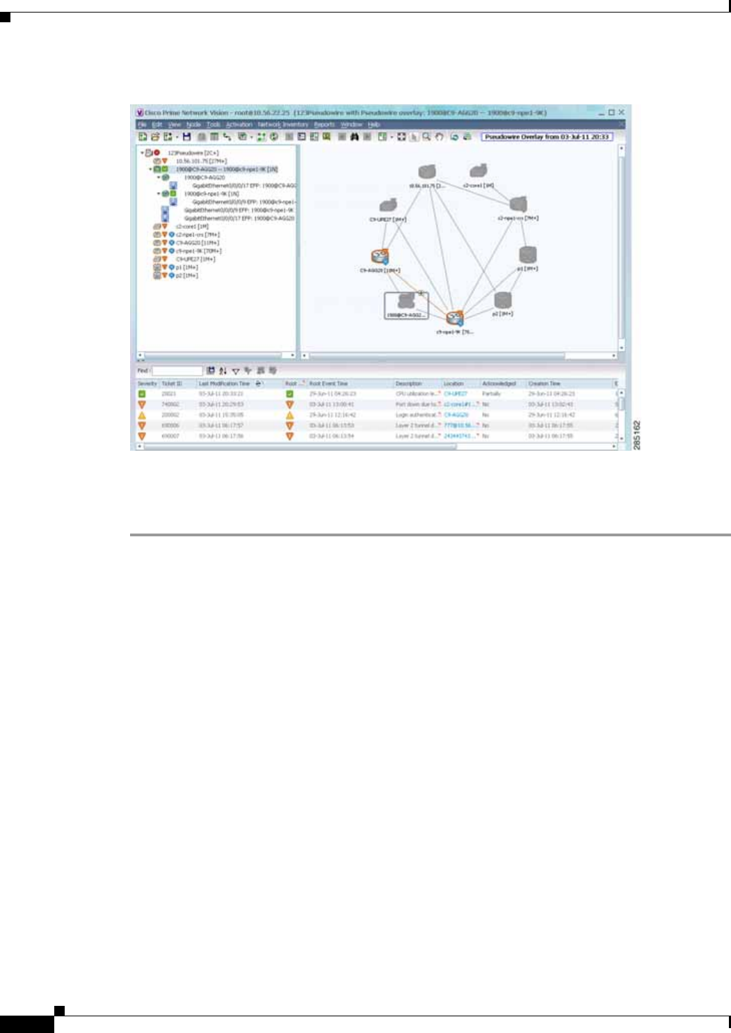
12-100
Cisco Prime Network 4.0 User Guide OL-29343-01
Chapter 12 Monitoring Carrier Ethernet Services
Working with Pseudowires
Figure 12-62 Pseudowire Overlay in Prime Network Vision
Step 5 To hide and view the overlay, click Hide Overlay/Show Overlay in the toolbar. The button toggles
depending on whether the overlay is currently displayed or hidden.
Step 6 To remove the overlay, choose Choose Overlay Type > None.
Monitoring the Pseudowire Headend
A pseudowire (PW) is an emulation of a point-to-point connection over a packet-switching network
(PSN). It operates over a uniform packet-based access/aggregation network. The composite L2 AC and
the PW segment together form a point-to-point virtual CE-PE link that functions like a traditional CE-PE
link technology.
Figure 12-63 displays a typical pseudowrie deployment over core network and Figure 12-64 displays a
pseduowire deployment over access network.
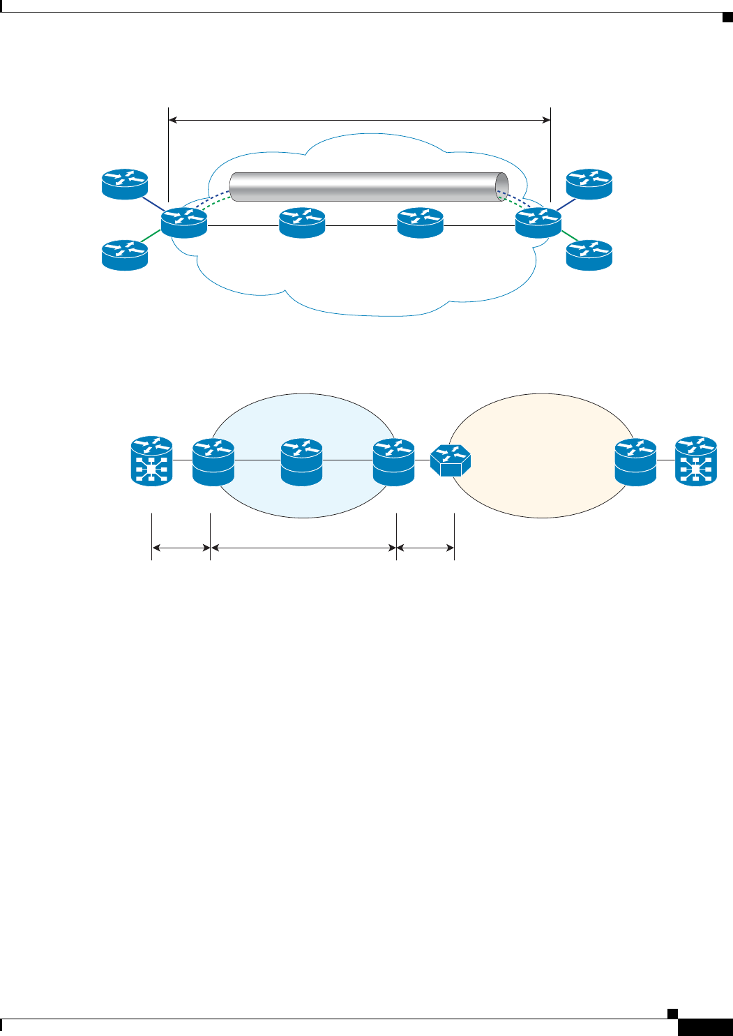
12-101
Cisco Prime Network 4.0 User Guide
OL-29343-01
Chapter 12 Monitoring Carrier Ethernet Services Working with Pseudowires
Figure 12-63 Pseudowire Deployment Over Core Network
Figure 12-64 Pseudowire Deployment Over Access Network
A pseudowire headend (PW-HE) virtual interface originates as a PW on an access node and terminates
on a Layer 3 service instance on the service provider router. For example, a PWHE can originate on the
Layer 2 PW feeder node and terminate on a VRF instance on the Cisco CRS Router. You can configure
all ingress and egress QoS function on the PW-HE interface, including policing, shaping, queuing, and
hierarchical policies.
In other words, the PW-HE is a technology that allows termination of access or aggregation pseduowires
into an L2 or L3 domain. It allows us to replace a 2-node solution with a 1-node solution. Without a
PW-HE, a L2 PE node must terminate a PW and then handoff the data to a S-PE via an Access Circuit.
The following figure displays the PW-HE interface:
243510
PW
CE1
PE2
PE2PE1
PE1
CE2
CE1
CE2
320494
CE L2 PE L2 PE S-PE PEP1
Access Network
Global IP/MPLS
Cor Network
PWAC AC
CE-2
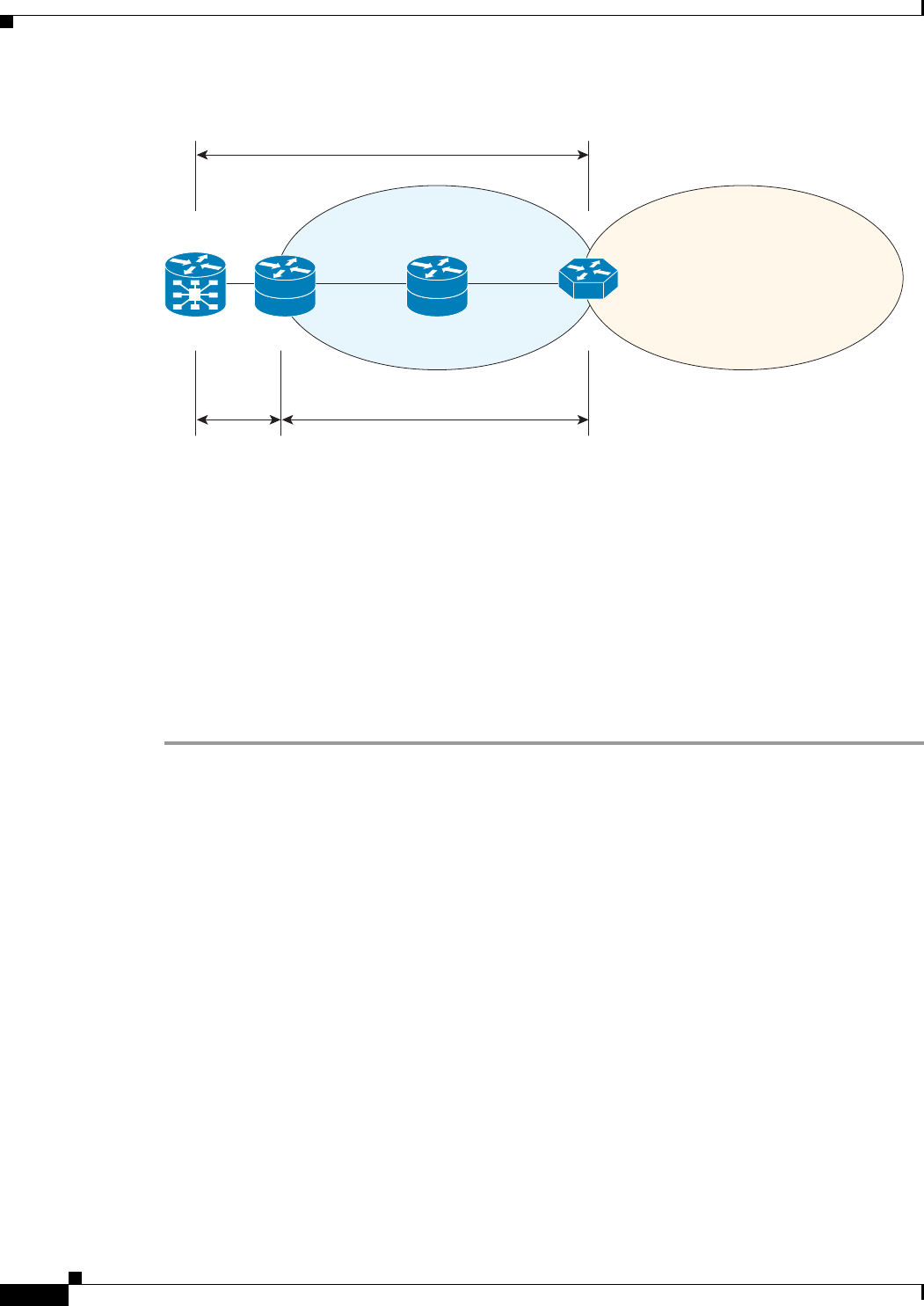
12-102
Cisco Prime Network 4.0 User Guide OL-29343-01
Chapter 12 Monitoring Carrier Ethernet Services
Working with Pseudowires
Figure 12-65 PW-HE Interface
The PW-HE interface is treated like any existing L3 interface and operates on one of the following nodes:
• Bridged interworking (VC type 5 or 4) node—PW will carry customer Ethernet frames with IP
payload. The S-PE device must perform ARP resolution for customer IP addresses learnt over
PW-HE, which acts as a broadcast interface.
• IP interworking node (VC type 11)—The PW-HE acts as a point-to-point interface. Hence, there will
be two types of PW-HE interface-PW-Ether and PW-IW. These PW’s can terminate into a VRF or
the IP global table on SP-E.
Viewing the PW-HE configuration
To view the PW-HE configuration:
Step 1 Right-click the required device in Prime Network Vision and choose Inventory.
Step 2 In the logical inventory window, choose Logical Inventory > PW-HE. The list of PW-HE interfaces
configured in Prime Network are displayed in the content pane.
Step 3 From the PW-HE node, choose a PW-HE interface. The PW-HE interface details are displayed in the
content pane as shown in Figure 12-66.
Layer3 Peering
320493
CE L2
A-PE S-PE
P1
MPLS Access
Network
Global IP/MPLS
Cor Network
PWAC
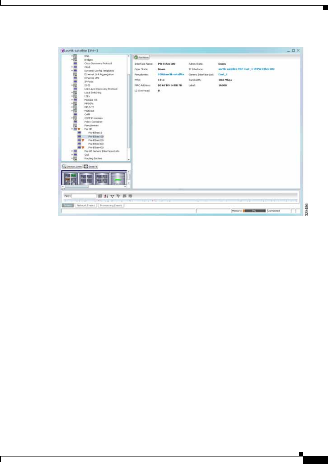

12-104
Cisco Prime Network 4.0 User Guide OL-29343-01
Chapter 12 Monitoring Carrier Ethernet Services
Working with Pseudowires
You can also view the following configuration details for a PW-HE interface:
• Viewing PW-HE Configured as a Local Interface under Pseudowire, page 12-104
• Viewing PW-HE Generic Interface List, page 12-105
• Viewing PW-HE as an Associated Entity for a Routing Entity, page 12-105
• Viewing PW-HE as an Associated Entity for a VRF, page 12-105
Viewing PW-HE Configured as a Local Interface under Pseudowire
To view the local interface details:
Step 1 Right-click the required device in Prime Network Vision and choose Inventory.
Step 2 In the logical inventory window, choose Logical Inventory > Pseudowire. The list of Pseudowire
interfaces configured in Prime Network are displayed in the content pane. For more information on
Pseudowire properties, see Viewing Pseudowire Properties, page 12-93.
Table 12-42 PW-HE Interface Details
Field Description
Interface Name The unique name to identify the PW-HE interface.
Admin State The administrative state of the PW-HE, which can be any one of the
following:
• Up
• Down
Oper State The operational state of the PW-HE, which can be any one of the following:
• Up
• Down
IP Interface The IP interface for the PW-HE, which when clicked will take you either to
the associated VRF interface site under the VRF node or the associated IP
Interface under the Routing Entity node.
Pseudowire The pseudowire to which the PW-HE is associated with, which when clicked
will take you to the Pseudowire node.
Generic Interface List The generic interface list linked to the PW-HE, which when clicked will take
you to the relevant node under the PW-HE Generic Interfaces Lists node.
MTU The maximum number of transmission units (in bytes) for the PW-HE
interface.
Bandwidth The bandwidth (in kbits) for the PW-HE interface.
MAC Address The MAC address specified for the PW-HE interface, which is generally in
the xxx.xxx.xxx format.
Label The MPLS label for the PW-HE interface.
L2 Overhead The layer 2 overhead (in bytes) configured on the PW-HE interface, which
can be any value between 0 and 64. This field defaults to 0.

12-105
Cisco Prime Network 4.0 User Guide
OL-29343-01
Chapter 12 Monitoring Carrier Ethernet Services Working with Pseudowires
Viewing PW-HE Generic Interface List
To view the PW-HE generic interface list:
Step 1 Right-click the required device in Prime Network Vision and choose Inventory.
Step 2 In the logical inventory window, choose Logical Inventory > PW-HE Generic Interface List. The list
of generic interfaces configured in Prime Network are displayed in the content pane.
Step 3 From the PW-HE Generic Interface List node, choose a generic interface list. The interface details are
displayed in the content pane.
Table 12-43 displays the PW-HE Generic Interface List details.
Viewing PW-HE as an Associated Entity for a Routing Entity
To view the routing entity details for a PW-HE:
Step 1 Right-click the required device in Prime Network Vision and choose Inventory.
Step 2 In the logical inventory window, choose Logical Inventory > Routing Entities > Routing Entity. The
routing entity details for the PW-HE is displayed in the content pane. For more information on Routing
entity details, see Viewing Routing Entities, page 18-31.
Viewing PW-HE as an Associated Entity for a VRF
To view the VRF details for a PW-HE:
Step 1 Right-click the required device in Prime Network Vision and choose Inventory.
Step 2 In the logical inventory window, choose Logical Inventory > VRF > PW-HE node. The VRF details for
the PW-HE is displayed in the content pane. For more information on VRF details, see Viewing VRF
Properties, page 18-27.
Table 12-43 PW-HE Generic Interface List Details
Field Description
Generic Interface The name of the generic interface list.
Interfaces tab
Interface The Ethernet Link Aggregation Group (LAG) for the PW-HE service, which
when clicked will take you to the LAG node.

12-106
Cisco Prime Network 4.0 User Guide OL-29343-01
Chapter 12 Monitoring Carrier Ethernet Services
Working with Ethernet Services
Working with Ethernet Services
Ethernet services are created when the following business elements are linked to one another:
• Network VLAN and bridge domain are linked through a shared EFP.
• Network VLAN and VPLS instance are linked through either of the following:
–
A shared, standalone EFP.
–
A shared switching entity.
• Network VLAN and network pseudowire (single or multi-segment) are linked through either of the
following:
–
A shared, standalone EFP.
–
A shared switching entity.
• VPLS-EoMPLS connected via a shared access pseudowire endpoint.
• Network VLAN and cross-connect are connected by a shared EFP.
• Network VLAN and service link are connected by a shared EFP.
If a VPLS, network pseudowire, cross-connect, or network VLAN object is not connected to another
business element, it resides alone in an Ethernet service.
In releases prior to Prime Network Vision 3.8, EVC multiplex was discovered by means of Ethernet flow
point associations. Beginning with Prime Network Vision 3.8, multiplex capabilities were enhanced to
distinguish multiplexed services based on the Customer VLAN ID; that is, Prime Network Vision 3.9 is
Inner Tag-aware.
As a result, in environments in which service providers have customers with multiplexed services, an
EVC can distinguish each service and create its own EVC representation.
Prime Network Vision discovers Ethernet services and enables you to add them to maps, apply overlays,
and view their properties. See the following topics for more information:
• Adding Ethernet Services to a Map, page 12-106
• Applying Ethernet Service Overlays, page 12-108
• Viewing Ethernet Service Properties, page 12-109
Adding Ethernet Services to a Map
You can add the Ethernet services that Prime Network Vision discovers to maps as required.
To add an Ethernet service to a map:
Step 1 In Prime Network Vision, select the required map or domain.
Step 2 Open the Add Ethernet Service to map dialog box in either of the following ways:
• In the toolbar, choose Add to Map > Ethernet Service.
• In the menu bar, choose File > Add to Map > Ethernet Service.
Step 3 In the Add Ethernet Service dialog box, do either of the following:
• To search for specific elements:
a. Choose Search, and then choose a search category: EVC Terminating EFPs, Name, or System
Name.
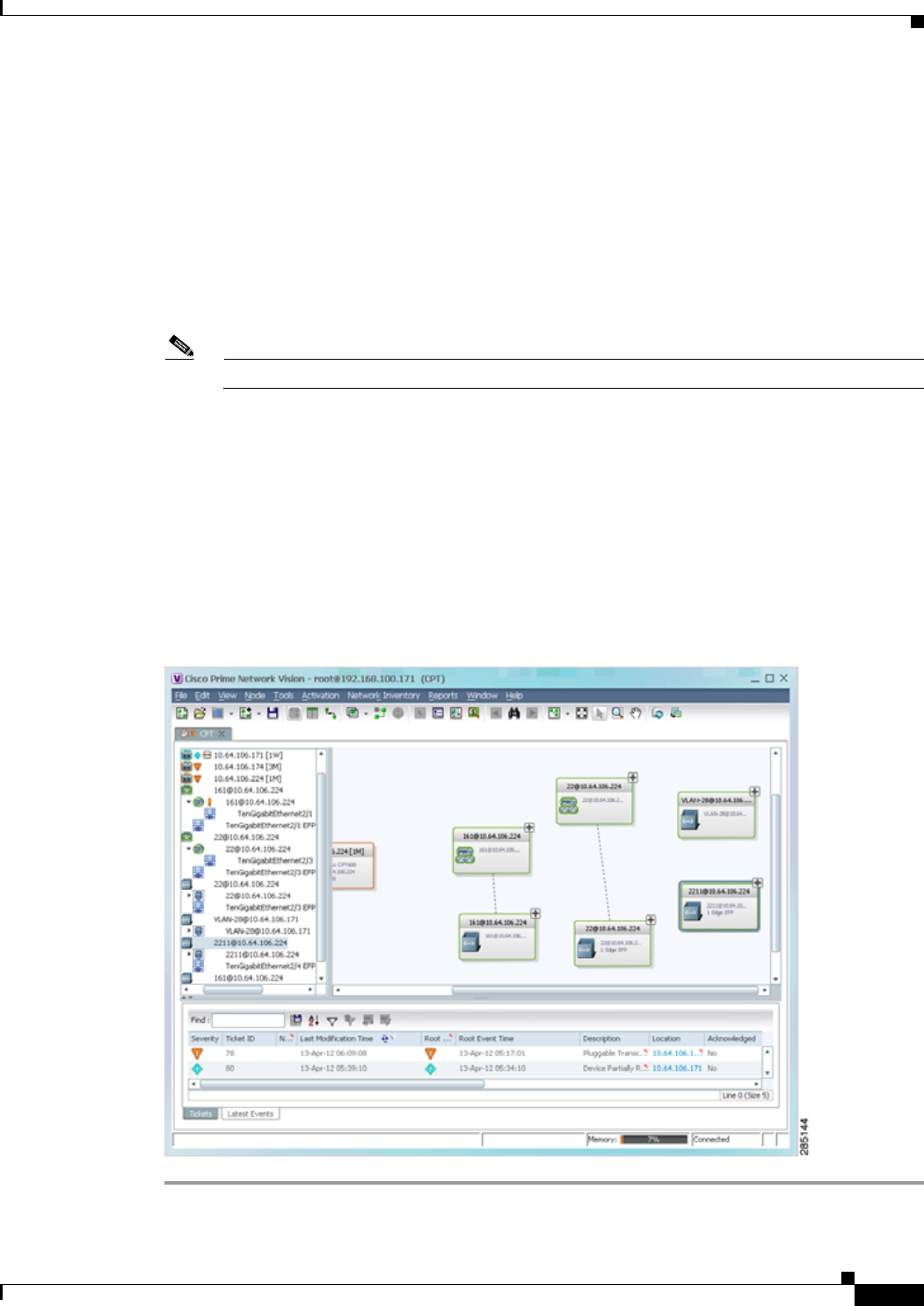
12-107
Cisco Prime Network 4.0 User Guide
OL-29343-01
Chapter 12 Monitoring Carrier Ethernet Services Working with Ethernet Services
b. To narrow the display to a range of Ethernet services or a group of Ethernet services, enter a
search string in the search field.
c. Click Go.
For example, if you choose Name and enter EFP1, the network elements that have names beginning
with EFP1 are displayed.
• To view all available Ethernet services, choose Show All and click Go.
The available elements that meet the specified search criteria are displayed in the Add Ethernet Service
dialog box in table format. The dialog box also displays the date and time at which the list was generated.
To update the list, click Refresh.
Note If an element is not included in your scope, it is displayed with the locked device icon.
For information about sorting and filtering the table contents, see Filtering and Sorting Tabular Content,
page 2-42.
Step 4 In the Add Ethernet Service dialog box, select the elements that you want to add. You can select and add
multiple elements by pressing Ctrl while selecting individual elements or by pressing Ctrl +Shift to
select a group of elements.
Step 5 Click OK.
The Ethernet service is displayed in the navigation pane and in the content area. In addition, any
associated tickets are displayed in the ticket pane. See Figure 12-67.
Figure 12-67 Ethernet Service in Prime Network Vision
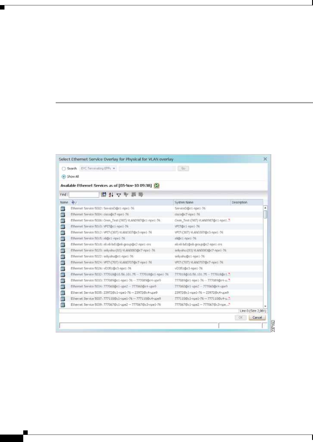
12-108
Cisco Prime Network 4.0 User Guide OL-29343-01
Chapter 12 Monitoring Carrier Ethernet Services
Working with Ethernet Services
The Ethernet service information is saved with the map in the Prime Network database.
Applying Ethernet Service Overlays
An Ethernet service overlay allows you to isolate the parts of a network that are being used by a specific
Ethernet service.
To apply an Ethernet service overlay:
Step 1 In Prime Network Vision, choose the map in which you want to apply an overlay.
Step 2 From the toolbar, choose Choose Overlay Type > Ethernet Service.
Figure 12-68 shows an example of the Select Ethernet Service Overlay for map dialog box.
Figure 12-68 Select Ethernet Service Overlay Dialog Box
Step 3 Select the required Ethernet Service for the overlay.
Step 4 Click OK.
The elements being used by the selected Ethernet service are highlighted in the map while the other
elements are dimmed, as shown in Figure 12-69.
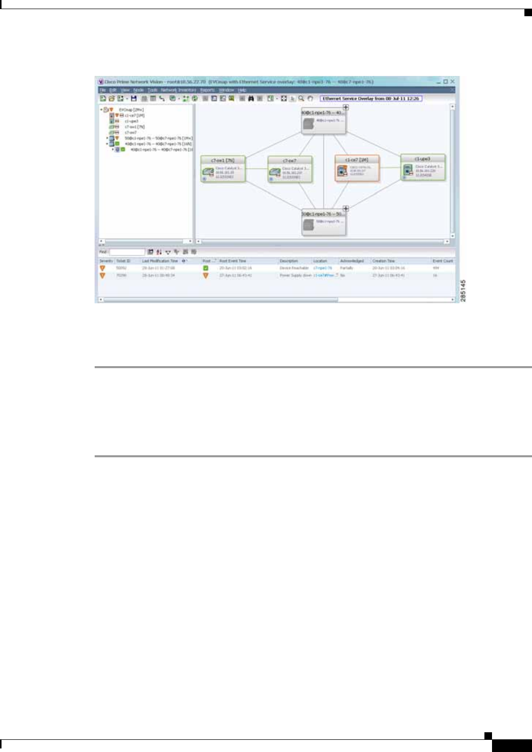
12-109
Cisco Prime Network 4.0 User Guide
OL-29343-01
Chapter 12 Monitoring Carrier Ethernet Services Working with Ethernet Services
Figure 12-69 Ethernet Service Overlay in Prime Network Vision
Step 5 To hide and view the overlay, click Hide Overlay/Show Overlay in the toolbar. The button toggles
depending on whether the overlay is currently displayed or hidden.
Step 6 To remove the overlay, choose Choose Overlay Type > None.
Viewing Ethernet Service Properties
To view Ethernet service properties:
Step 1 In Prime Network Vision, select the map containing the required Ethernet service.
Step 2 In the navigation or map pane, right-click the Ethernet service and choose Properties.
Figure 12-70 shows an example of an Ethernet Service Properties window with the EVC Terminating
table. Depending on the types of service in the EVC, tabs might be displayed. For example, if the EVC
contains two network VLANs and a VPLS, tabs are displayed for the following:
• EVC Terminating table
• Network VLANs
• VPLS
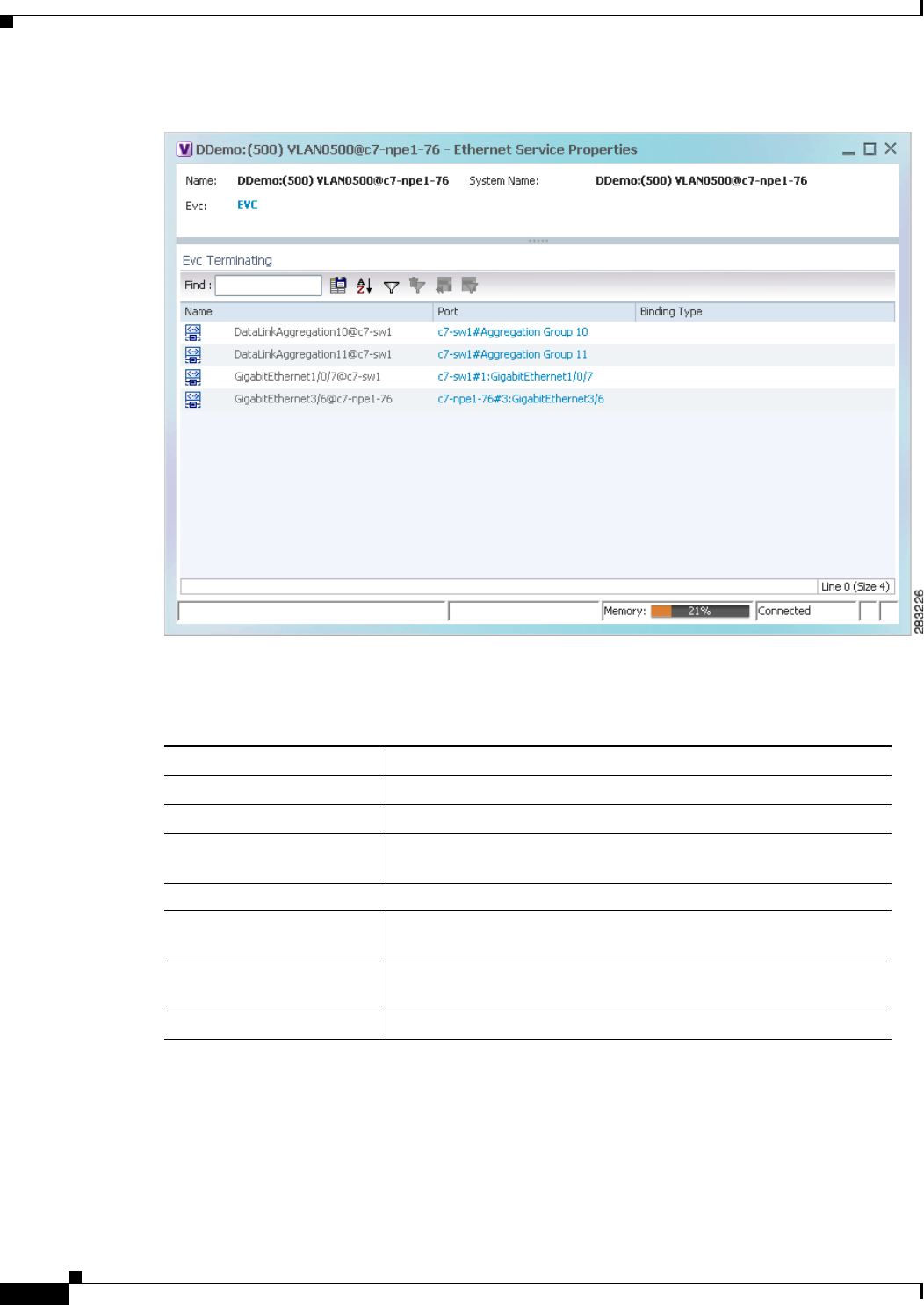
12-110
Cisco Prime Network 4.0 User Guide OL-29343-01
Chapter 12 Monitoring Carrier Ethernet Services
Working with Ethernet Services
Figure 12-70 Ethernet Service Properties Window
Table 12-44 describes the information that is displayed for an Ethernet service.
Step 3 To view the EVC Properties window, click the hyperlink in the EVC field.
Figure 12-71 shows an example of the EVC Properties window.
Table 12-44 Ethernet Service Properties Window
Field Description
Name Ethernet service name.
System Name Name that Prime Network Vision assigns to the Ethernet service.
EVC Name of the EVC associated with the Ethernet service, hyperlinked
to the EVC Properties window.
EVC Terminating Table
Name EVC name, represented by the interface name, EFP, and the EFP
name.
Network Element Hyperlinked entry to the specific interface and EFP in physical
inventory.
Port Hyperlinked entry to the specific interface in physical inventory.
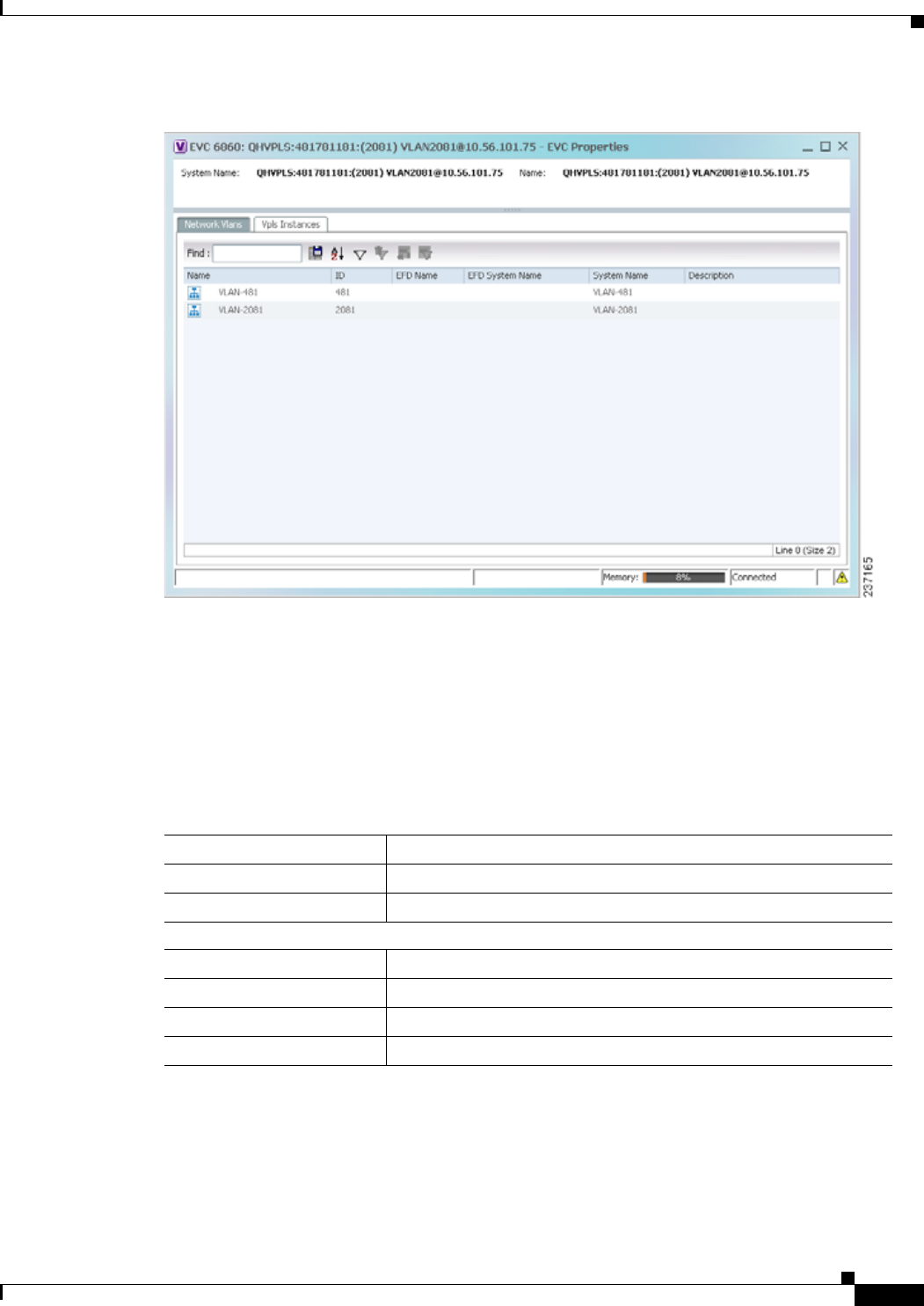
12-111
Cisco Prime Network 4.0 User Guide
OL-29343-01
Chapter 12 Monitoring Carrier Ethernet Services Working with Ethernet Services
Figure 12-71 EVC Properties Window
Table 12-45 describes the information that is displayed in the EVC Properties window. The tabs that are
displayed depend on the services included in the EVC. For example, if the EVC contains two network
VLANs and a VPLS, tabs are displayed for the following:
• EVC Terminating table
• Network VLANs
• VPLS
Table 12-45 EVC Properties Window
Field Description
System Name Name of the system on which the EVC is configured.
Name EVC name.
Cross-Connects Table
Name Cross-connect name.
Segment 1 Identifier of the first cross-connect endpoint.
Segment 2 Identifier of the second cross-connect endpoint.
System Name Cross-connect system name.

12-112
Cisco Prime Network 4.0 User Guide OL-29343-01
Chapter 12 Monitoring Carrier Ethernet Services
Viewing IP SLA Responder Service Properties
Viewing IP SLA Responder Service Properties
Cisco IOS Service Level Agreements (SLAs) software allows you to analyze IP service levels for IP
applications and services by using active traffic monitoring to measure network performance.
The IP SLA responder is a component embedded in the destination Cisco device that allows the system
to anticipate and respond to IP SLAs request packets. The responder provides accurate measurements
without requiring dedicated probes. The responder uses the Cisco IOS IP SLAs Control Protocol to
provide a mechanism through which it can be notified on which port it should listen and respond.
Two-Way Active Measurement Protocol (TWAMP) defines a standard for measuring round-trip network
performance between any two devices that support the protocol.
Prime Network Vision supports IP SLA Responder service on the following devices:
• Cisco 3400ME and 3750ME devices running Cisco IOS 12.2(52)SE.
• Cisco MWR2941 devices running Cisco CSR 3.2.
To view IP SLA Responder service properties:
Step 1 In Prime Network Vision, double-click the device configured for IP SLA Responder service.
Step 2 In the inventory window, choose Logical Inventory > IP SLA Responder.
IP SLA Responder properties are displayed as shown in Figure 12-72.
Network VLANs Tab
Name VLAN name.
ID VLAN identifier.
EFD Name Name of the Ethernet flow domain.
EFD System Name Name that Prime Network Vision assigns to the EFD.
System Name VLAN system name.
Description Brief description of the VLAN.
Network Pseudowires Tab
Name Pseudowire name.
System Name System on which the pseudowire is configured.
Description Brief description of the pseudowire.
Pseudowire Type Type of pseudowire.
Is Multisegment Pseudowire Whether or not the pseudowire is multisegment: True or False.
VPLS Instances Tab
Name VPLS instance name.
System Defined Name Name that Prime Network Vision assigns to the VPLS instance.
VPN ID Identifier of associated VPN.
Table 12-45 EVC Properties Window (continued)
Field Description
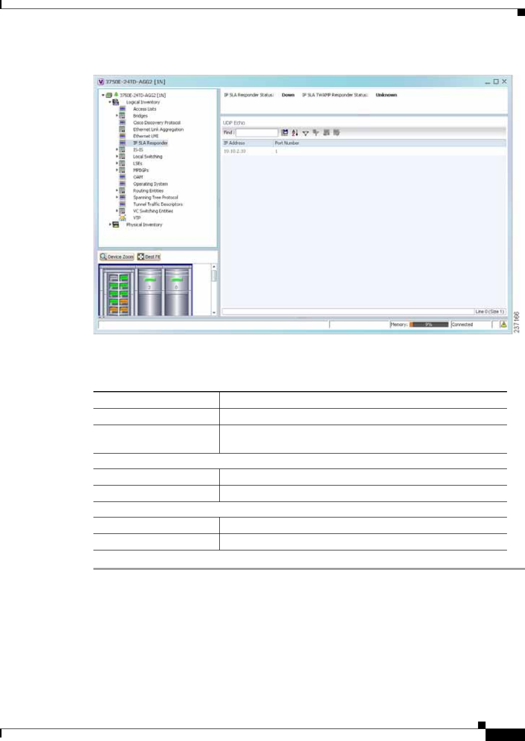
12-113
Cisco Prime Network 4.0 User Guide
OL-29343-01
Chapter 12 Monitoring Carrier Ethernet Services Viewing IP SLA Responder Service Properties
Figure 12-72 IP SLA Responder in Logical Inventory
Table 12-46 describes the properties displayed for IP SLA Responder service.
Table 12-46 IP SLA Responder Properties in Logical Inventory
Field Description
IP SLA Responder Status Status of the IP SLA Responder: Up or Down.
IP SLA TWAMP Responder
Status Status of the IP SLA TWAMP responder: Up or Down.
UDP Echo Tab
IP Address Destination IP address used for the UDP echo operation.
Port Number Destination port number used for the UDP echo operation.
TCP Connect Tab
IP Address Destination IP address used for the TCP connect operation.
Port Number Destination port number used for the TCP connect operation.
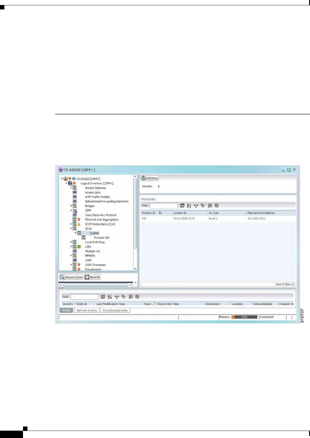
12-114
Cisco Prime Network 4.0 User Guide OL-29343-01
Chapter 12 Monitoring Carrier Ethernet Services
Viewing IS-IS Properties
Viewing IS-IS Properties
Intermediate System-to-Intermediate System (IS-IS) protocol is a routing protocol developed by the
ISO. It is a link-state protocol where IS routers exchange routing information based on a single metric
to determine network topology. It behaves in a manner similar to OSPF in the TCP/IP network.
IS-IS networks contain end systems, intermediate systems, areas, and domains. End systems are user
devices. Intermediate systems are routers. Routers are organized into local groups called areas, and areas
are grouped into a domain. For configuring IS-IS, see Configuring IS-IS, page 12-121.
To view IS-IS properties:
Step 1 In Prime Network Vision, double-click the device configured for IS-IS.
Step 2 In the inventory window, choose Logical Inventory > IS-IS > System.
Figure 12-73 shows an example of the IS-IS window with the Process table in logical inventory.
Figure 12-73 IS-IS Window in Logical Inventory
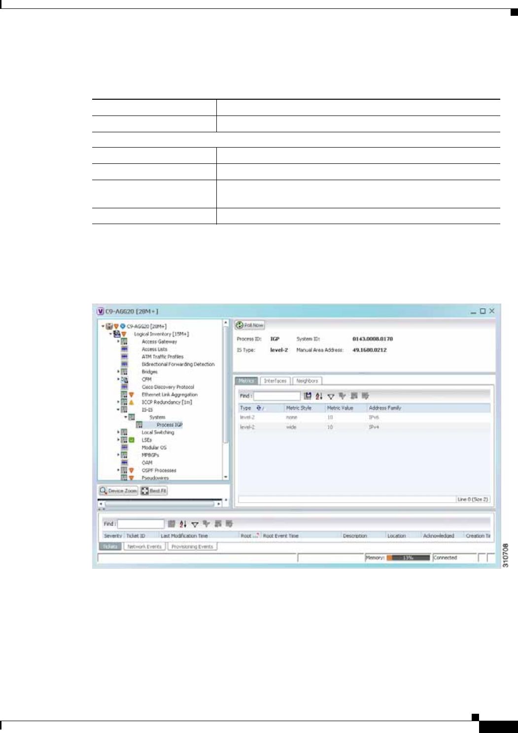
12-115
Cisco Prime Network 4.0 User Guide
OL-29343-01
Chapter 12 Monitoring Carrier Ethernet Services Viewing IS-IS Properties
Table 12-47 describes the information that is displayed in this window and the Processes table.
Step 3 To view IS-IS process information, choose Logical Inventory > IS-IS > Process nnn.
Figure 12-74 shows an example of the information that is displayed for the IS-IS process.
Figure 12-74 IS-IS Process Properties in Logical Inventory
Table 12-47 IS-IS Properties in Logical Inventory - Processes Table
Field Description
Version Version of IS-IS that is implemented.
Processes Table
Process ID Identifier for the IS-IS process.
System ID Identifier for this Intermediate System.
IS Type Level at which the Intermediate System is running: Level 1, Level
2, or Level 1-2.
Manual Area Address Address assigned to the area.

12-116
Cisco Prime Network 4.0 User Guide OL-29343-01
Chapter 12 Monitoring Carrier Ethernet Services
Viewing IS-IS Properties
Table 12-48 describes the information that is displayed for the selected IS-IS process.
Table 12-48 IS-IS Process Properties in Logical Inventory
Field Description
Process Unique identifier for the IS-IS process.
System ID Identifier for this Intermediate System.
IS Type Level at which the Intermediate System process is running: Level 1,
Level 2, or Level 1-2.
Manual Area Address Address assigned to the area.
Metrics Tab
IS Type Level at which the Intermediate System is running: Level 1, Level
2, or Level 1-2.
Metric Style Metric style used: Narrow, Transient, or Wide.
Metric Value Metric value assigned to the link. This value is used to calculate the
path cost via the links to destinations. This value is available for
Level 1 or Level 2 routing only.
If the metric style is Wide, the value can range from 1 to 16777214.
If the metric style is Narrow, the value can range from 1 to 63.
The default value for active IS-IS interfaces is 10, and the default
value for inactive IS-IS interfaces is 0.
Address Family IP address type used: IPv4 or IPv6.
Interfaces Tab
Interface Name Interface name.
Neighbors Tab
System ID Identifier for the neighbor system.
Interface Neighbor interface name.
IP Address Neighbor IP address.
Type IS type for the neighbor: Level 1, Level 2, or Level 1-2.
SNPA Subnetwork point of attachment (SNPA) for the neighbor.
Hold Time Holding time, in seconds, for this adjacency. The value is based on
received IS-to-IS Hello (IIH) PDUs and the elapsed time since
receipt.
State Administrative status of the neighbor system: Up or Down.
Address Family IP address type used by the neighbor: IPv4 or IPv6.
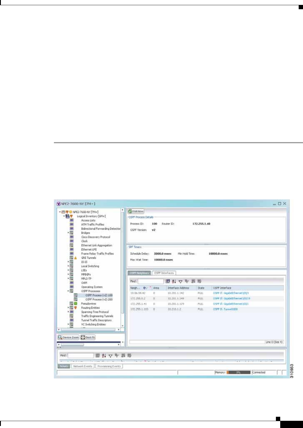
12-117
Cisco Prime Network 4.0 User Guide
OL-29343-01
Chapter 12 Monitoring Carrier Ethernet Services Viewing OSPF Properties
Viewing OSPF Properties
Prime Network Vision supports the following versions of OSPF:
• OSPFv1
• OSPFv2
• OSPFv3
Using Prime Network Vision you can view OSPF properties for:
• OSPF processes, including the process identifier and OSPF version.
• OSPF network interfaces, such as the area identifier, network type, and status.
• OSPF neighbors, including the neighbor identifier, neighbor interface address, and status.
To view OSPF properties:
Step 1 In Prime Network Vision, double-click the device configured for OSPF.
Step 2 To view OSPF processes, choose Logical Inventory > OSPF Processes > OSPF Process (vn) ID where
vn represents the OSPF version and ID is the OSPF process identifier.
For example, in Figure 12-75, the entry in the navigation tree is OSPF Process (v2) 10.
Figure 12-75 OSPF Processes in Logical Inventory
Table 12-49 describes the information that is displayed for OSPF processes.

12-118
Cisco Prime Network 4.0 User Guide OL-29343-01
Chapter 12 Monitoring Carrier Ethernet Services
Viewing OSPF Properties
Table 12-49 OSPF Processes in Logical Inventory
Field Description
OSPF Process Details
Process ID Unique process identifier.
Router ID Router IP address.
OSPF Version OSPF version: v1, v2, or v3.
SPF Timers
Schedule Delay Number of milliseconds to wait after a change before calculating the shortest path first (SPF).
Min Hold Time Minimum number of milliseconds to wait between two consecutive SPF calculations.
Max Wait Time Maximum number of milliseconds to wait between two consecutive SPF calculations.
OSPF Neighbors Table
Neighbor ID OSPF neighbor IP address.
Area OSPF area identifier.
Interface Address IP address of the interface on the neighbor configured for OSPF.
State State of the communication with the neighbor: Down, Attempt, Init, 2-Way, Exstart, Exchange,
Loading, and Full.
OSPF Interface Hyperlinked entry to the OSPF Interface Properties window.
The OSPF Interfaces window displays the same information as the OSPF Interfaces Table below.
OSPF Interfaces Table
IP Interface OSPF interface, hyperlinked to the relevant entry in the routing entity IP Interfaces table in logical
inventory.
For more information about the IP Interfaces table, see Table 18-12.
Internet Address OSPF interface IP address.
Area ID OSPF area identifier.
Priority Eight-bit unsigned integer that specifies the priority of the interface. Values range from 0 to 255. Of
two routers, the one with the higher priority takes precedence.
Cost Specified cost of sending a packet on the interface, expressed as a metric. Values range from 1 to
65535.
Status State of the interface: Up or Down.
State OSPF state: BDR, DR, DR-Other, Waiting, Point-to-Point, or Point-to-Multipoint.
Network Type Type of OSPF network: Broadcast, Nonbroadcast Multiple Access (NBMA), Point-to-Multipoint,
Point-to-Point, or Loopback.
DR Address Designated router IP address.
BDR Address Backup designated router IP address.

12-119
Cisco Prime Network 4.0 User Guide
OL-29343-01
Chapter 12 Monitoring Carrier Ethernet Services Configuring REP and mLACP
Configuring REP and mLACP
The following commands can be launched from the inventory by right-clicking the appropriate node and
selecting Commands. Before executing any commands, you can preview them and view the results. If
desired, you can also schedule the commands. For details on the software versions Prime Network
supports for these network elements, see the Cisco Prime Network 4.0 Supported Cisco VNEs. To run
the REP and mLACP commands, the software on the network element must support these technology.
Additional commands may be available for your devices. New commands are often provided in Prime
Network Device Packages, which can be downloaded from the Prime Network software download site.
For more information on how to download and install DPs and enable new commands, see the
information on “Adding Additional Device (VNE) support” in the Cisco Prime Network 4.0
Administrator Guide.
Note You might be prompted to enter your device access credentials while executing a command. Once you
have entered them, these credentials will be used for every subsequent execution of a command in the
same GUI client session. If you want to change the credentials, click Edit Credentials. The Edit
Credentials button will not be available for SNMP commands or if the command is scheduled for a later
time.
Command Navigation Description
REP Command
Show REP Segment
Information Commands > Show This action performed at the command
the launch point.
mLACP Commands
Show Group
Show MPLS LDP
Show Channel
Show LACP Internal
Commands > Show These actions are performed at the
command the launch point.

12-120
Cisco Prime Network 4.0 User Guide OL-29343-01
Chapter 12 Monitoring Carrier Ethernet Services
Using Pseudowire Ping and Show Commands
Using Pseudowire Ping and Show Commands
The Ping Pseudowire and Display Pseudowire commands can be launched from the inventory by
right-clicking the appropriate node and selecting Commands. Before executing any commands, you can
preview them and view the results. If desired, you can also schedule the commands.
Additional commands may be available for your devices. New commands are often provided in Prime
Network Device Packages, which can be downloaded from the Prime Network software download site.
For more information on how to download and install DPs and enable new commands, see the
information on “Adding Additional Device (VNE) support” in the Cisco Prime Network 4.0
Administrator Guide.
Note You might be prompted to enter your device access credentials while executing a command. Once you
have entered them, these credentials will be used for every subsequent execution of a command in the
same GUI client session. If you want to change the credentials, click Edit Credentials. The Edit
Credentials button will not be available for SNMP commands or if the command is scheduled for a later
time.
Command Navigation Description
Ping Pseudowire Logical Inventory >
Pseudowires > right-click the
interface > Commands >
Configure >
Use the Ping Pseudowire command to ping the
peer router with a tunnel ID from a single or
multisegment pseudowire. This command can
be used to verify connectivity between any set
of PE routers in the pseudowire path. For a
multisegment pseudowire this command can be
used to verify that all the segments of the
multisegment pseudowire are operating. You
can use this command to verify connectivity at
the following pseudowire points:
• From one end of the pseudowire to the
other
• From one of the pseudowires to a specific
segment
• The segment between two adjacent PE
routers
You can choose to ping the peer router by
default or provide the IP of the required
destination router to ping.
Display
Pseudowire Logical
Inventory > Pseudowire >
right-click the required
interface > Commands >
Show > Display Pseudowire
Use the Display Pseudowire command to show
the MPLS Layer 2 (L2) transport binding using
tunnel identifier. MPLS L2 transport binding
allows you to identify the VC label binding
information. This command can be used to
display information about the pseudowire
switching point.

12-121
Cisco Prime Network 4.0 User Guide
OL-29343-01
Chapter 12 Monitoring Carrier Ethernet Services Configuring IS-IS
Configuring IS-IS
In order to enable IS-IS for IP on a Cisco router and have it exchange routing information with other
IS-IS enabled routers, you must perform these two tasks:
• Enable the IS-IS process and assign area
• Enable IS-IS for IP routing on an interface
You can configure the router to act as a Level 1 (intra-area) router, as Level 1-2 (both a Level 1 router
and a Level 2 router), or as Level 2 (an inter-area router only).
The IS-IS commands helps you to configure the IS-IS on a Cisco router. These commands can be
launched from the logical inventory. Before executing any commands, you can preview them and view
the results. If desired, you can also schedule the commands.
The table below lists the IS-IS configuration commands. To run the ISIS commands, the software on the
network element must support ISIS technology. For details on the software versions Prime Network
supports for the ISIS supported network elements, see the Cisco Prime Network 4.0 Supported Cisco
VNEs.
Additional commands may be available for your devices. New commands are often provided in Prime
Network Device Packages, which can be downloaded from the Prime Network software download site.
For more information on how to download and install DPs and enable new commands, see the
information on “Adding Additional Device (VNE) support” in the Cisco Prime Network 4.0
Administrator Guide.
Note You might be prompted to enter your device access credentials while executing a command. Once you
have entered them, these credentials will be used for every subsequent execution of a command in the
same GUI client session. If you want to change the credentials, click Edit Credentials. The Edit
Credentials button will not be available for SNMP commands or if the command is scheduled for a later
time.
Command Navigation Description
Create ISIS Router ISIS > right-click System >
Commands > Configuration Use this command to create an IS-IS
routing process and specify the area
for each instance of the IS-IS routing
process. An appropriate Network
Entity Title (NET) must be
configured to specify the area address
for the IS-IS area and system ID of
the router.
Multiple IS-IS processes can be
configured. Up to eight processes are
configurable. A maximum of five
IS-IS instances on a system are
supported.
Modify ISIS Router
Delete ISIS Router
ISIS > System > right-click Process
ID in content pane > Commands >
Configuration >
Use this command to modify or delete
an exisiting IS-IS routing
configuration for the specified
routing process.

12-122
Cisco Prime Network 4.0 User Guide OL-29343-01
Chapter 12 Monitoring Carrier Ethernet Services
Configuring IS-IS
Command Navigation Description
Create ISIS
Interface ISIS > System > right-click
Process ID in content pane >
Commands > Configuration >
Use these command to create or modify an
IS-IS routing process and assign it to a
specific interface, rather than to a
network.
Modify ISIS
Interface
Delete ISIS
Interface
ISIS > expand System > select a
Process > select Interfaces tab>
right-click on a Interface Name >
Commands > Configuration >
Create ISIS Address
Family
Modify ISIS
Address Family
Delete ISIS Address
Family
ISIS > System > right-click
Process ID in content pane >
Commands > Configuration
Configure or modify IS-IS routing to use
standard IP Version 4 (IPv4) and IP
Version 6 (IPv6) address prefixes.
Create ISIS
Interface Address
Family
Modify ISIS
Interface Address
Family
Delete ISIS
Interface Address
Family
ISIS > expand System > select a
Process > select Interfaces tab>
right-click on a Interface Name >
Commands > Configuration >
Configure IS-IS routing to use standard IP
Version 4 (IPv4) and IP Version 6 (IPv6)
address prefixes on an interface.
Show ISIS
Configuration ISIS > right-click System >
Commands > Show The show isis command displays general
information about an IS-IS instance and
protocol operation.

CHAPTER
13-1
Cisco Prime Network 4.0 User Guide
OL-29343-01
13
Monitoring Carrier Grade NAT Properties
Carrier Grade NAT is a large-scale Network Address Translation (NAT) that provides translation of
millions of private IPv4 addresses to public IPv4 addresses. These translations support subscribers and
content providers with a bandwidth throughput of at least 10 Gbps full-duplex.
Carrier Grade NAT addresses the IPv4 address completion problem. It employs Network Address and
Port Translation (NAPT) to aggregate many private IPv4 addresses into fewer public IPv4 addresses. For
example, a single public IPv4 address with a pool of 32,000 port numbers supports 320 individual private
IP subscribers, assuming that each subscriber requires 100 ports. Carrier Grade NAT also offers a way
to implement a graceful transition to IPv6 addresses.
Carrier Grade NAT attributes and instances are configured as a CRS-ADVSVC-PLIM card on
Cisco CRS-1 routers. To route internal public addresses to external public addresses, a VPN Routing and
Forwarding (VRF) instance is created. Interfaces are created for the VRF at the subscriber-side (private)
and the Internet-side (public). The VRF enables static or dynamic routing of protocols on the interfaces.
Cisco Prime Network supports the following instances for Carrier Grade NAT:
• Stateful Address Translation- NAT44 Stateful
• Stateless Address Translation- NAT 64 Stateless (X-LAT)
• IPv6 rapid deployment (6rd)
Each Carrier Grade NAT instance has several attributes listed under them, such as preferred location,
address pools, associated interfaces, and statistics. The attributes are grouped under related categories.
The categories and attributes are listed below:
Note IPv4 Network Address Translation (NAT44) is not supported for devices running Cisco IOS XR
software version 4.0.
The following topics describe how to use Prime Network Vision to view Carrier Grade NAT properties:
• User Roles Required to View Carrier Grade NAT Properties, page 13-2
• Viewing Carrier Grade NAT Properties in Logical Inventory, page 13-2
• Viewing Carrier Grade NAT Properties in Physical Inventory, page 13-5
• Configuring CG NAT Service, page 13-6

13-2
Cisco Prime Network 4.0 User Guide OL-29343-01
Chapter 13 Monitoring Carrier Grade NAT Properties
User Roles Required to View Carrier Grade NAT Properties
User Roles Required to View Carrier Grade NAT Properties
This topic identifies the roles that are required to view Carrier Grade NAT properties in Prime Network
Vision. Prime Network determines whether you are authorized to perform a task as follows:
• For GUI-based tasks (tasks that do not affect elements), authorization is based on the default
permission that is assigned to your user account.
• For element-based tasks (tasks that do affect elements), authorization is based on the default
permission that is assigned to your account. That is, whether the element is in one of your assigned
scopes and whether you meet the minimum security level for that scope.
For more information on user authorization, see the Cisco Prime Network 4.0 Administrator Guide.
The following tables identify the tasks that you can perform:
• Table 13-1 identifies the tasks that you can perform if a selected element is not in one of your
assigned scopes.
• Table 13-2 identifies the tasks that you can perform if a selected element is in one of your assigned
scopes.
By default, users with the Administrator role have access to all managed elements. To change the
Administrator user scope, see the topic on device scopes in the Cisco Prime Network 4.0 Administrator
Guide.
Viewing Carrier Grade NAT Properties in Logical Inventory
To view Carrier Grade NAT properties in logical inventory:
Step 1 In Prime Network Vision, double-click the Cisco CRS device configured for Carrier Grade NAT.
Step 2 In the inventory window, click Logical Inventory > Carrier Grade NAT.
Table 13-1 Default Permission/Security Level Required for Viewing Carrier Grade NAT Properties
- Element Not in User’s Scope
Task Viewer Operator OperatorPlus Configurator Administrator
View Carrier Grade
NAT properties ————X
Using CG NAT
Configure, Delete, and
Show Commands
——— X X
Table 13-2 Default Permission/Security Level Required for Viewing Carrier Grade NAT Properties
- Element in User’s Scope
Task Viewer Operator OperatorPlus Configurator Administrator
View Carrier Grade
NAT properties XXXXX
Using CG NAT
Configure, Delete, and
Show Commands
——— X X
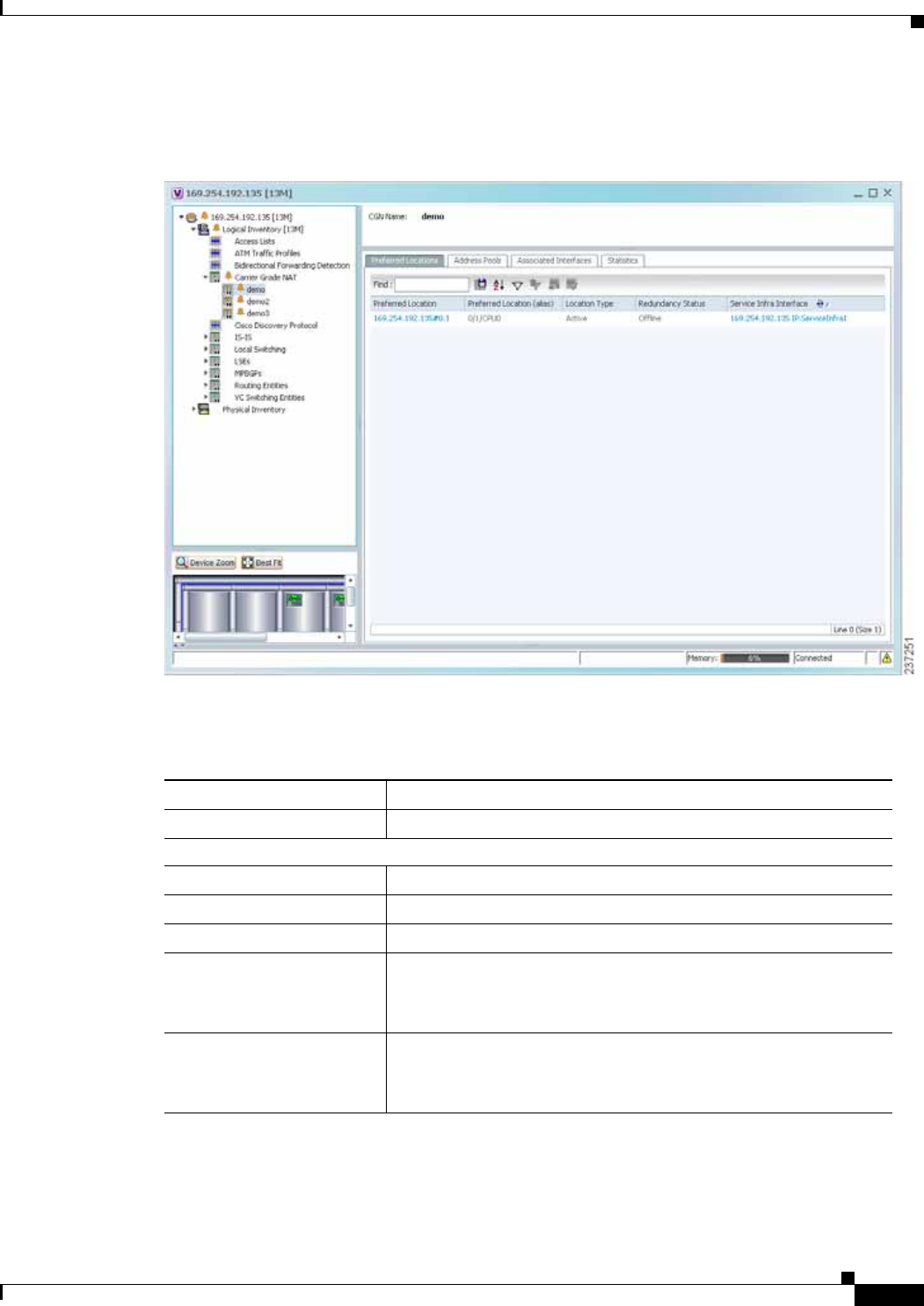
13-3
Cisco Prime Network 4.0 User Guide
OL-29343-01
Chapter 13 Monitoring Carrier Grade NAT Properties Viewing Carrier Grade NAT Properties in Logical Inventory
The Carrier Grade NAT properties are displayed in logical inventory as shown in Figure 13-1.
Figure 13-1 Carrier Grade NAT in Logical Inventory
Table 13-3 describes the Carrier Grade NAT properties that are displayed.
Table 13-3 Carrier Grade NAT Properties in Logical Inventory
Field Description
CGN Name Name of the Carrier Grade NAT service.
Preferred Location Tab
Preferred Location Hyperlinked entry to the card in physical inventory.
Preferred Location (alias) Location of module in clear text.
Location Type Configured type of location: Active or Standby.
Redundancy Status Redundancy state: Online or Offline.
If the field is empty, it means the data was not collected from the
device.
Service Infra Interface Hyperlinked entry to the routing entity in logical inventory.
For more information about routing entities in logical inventory, see
Viewing Routing Entities, page 18-31.

13-4
Cisco Prime Network 4.0 User Guide OL-29343-01
Chapter 13 Monitoring Carrier Grade NAT Properties
Viewing Carrier Grade NAT Properties in Logical Inventory
Address Pools Tab
Inside VRF Hyperlinked entry to the inside VRF in logical inventory.
For more information about VRF properties in logical inventory, see
Viewing VRF Properties, page 18-27.
Address Family Type of IP address in this pool: IPv4 or IPv6.
Outside VRF Hyperlinked entry to the outside VRF in logical inventory.
For more information about VRF properties in logical inventory, see
Viewing VRF Properties, page 18-27.
Address Pool Range of IP addresses that can be used for the service instance. If
an end address is not specified, the entire range of 255 addresses is
used for the address pool.
Associated Interfaces Tab
Interface Hyperlinked entry to the associated entry in logical inventory:
• For SVI service interfaces, hyperlinked entry to the routing
entity in logical inventory.
• For SVI service applications, hyperlinked entry to the VRF
entity in logical inventory.
Service Types Tab
Service Type Name Name of the Carrier Grade NAT service.
Service Type Type of Carrier Grade NAT service: 6RD, XLAT, or NAT44.
Statistics Tab
Statistics Name Name of the statistic.
For statistic names and descriptions, see Table 13-4.
Statistics Value Value of the statistic.
Table 13-3 Carrier Grade NAT Properties in Logical Inventory (continued)
Field Description

13-5
Cisco Prime Network 4.0 User Guide
OL-29343-01
Chapter 13 Monitoring Carrier Grade NAT Properties Viewing Carrier Grade NAT Properties in Physical Inventory
You can also display pool utilization by right-clicking a VNE and choosing Commands > Show > Pool
Utilization.
Viewing Carrier Grade NAT Properties in Physical Inventory
To view Carrier Grade NAT properties in physical inventory:
Step 1 In Prime Network Vision, double-click the Cisco CRS device configured for Carrier Grade NAT.
Step 2 To view Carrier Grade NAT properties configured on a specific interface, click Physical
Inventory > chassis > shelf > slot > card > interface. See Table 3-11 for a description of the
information displayed in the Subinterfaces table.
Step 3 To view Carrier Grade NAT properties configured on a Cisco CRS-CGSE-PLIM card, click Physical
Inventory > chassis > shelf > slot > PLIM-card.
Figure 13-2 shows an example of Carrier Grade NAT properties in physical inventory.
Table 13-4 Carrier Grade NAT Statistics in Logical Inventory
Statistic Name Description
Inside to outside drops port limit
exceeded Number of packets dropped because the port limit has been
exceeded. The value is calculated from the time Carrier Grade NAT
was configured and running on the card.
Inside to outside drops resource
depletion Number of packets that are dropped because no ports are available.
The value is calculated from the time Carrier Grade NAT was
configured and running on the card.
Inside to outside drops limit
system reached Number of packets that are dropped because the system limit has
been exceeded. The value is calculated from the time Carrier Grade
NAT was configured and running on the card.
Inside to outside forward rate Number of packets forwarded from the inside to the outside in the
last one second.
Outside to inside forward rate Number of packets forwarded from the outside to the inside in the
last one second.
Translations create rate Number of translation entries created in the last one second.
Translations delete rate Number of translation entries deleted in the last one second.
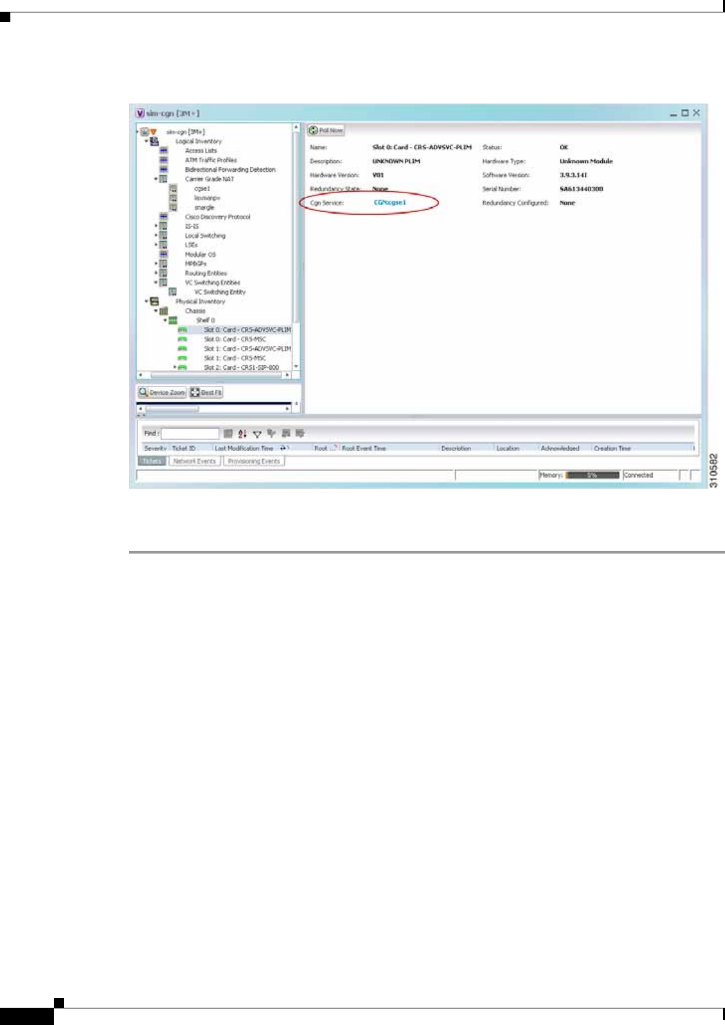
13-6
Cisco Prime Network 4.0 User Guide OL-29343-01
Chapter 13 Monitoring Carrier Grade NAT Properties
Configuring CG NAT Service
Figure 13-2 Carrier Grade NAT Properties in Physical Inventory
The field CGN Service is displayed, and the entry is hyperlinked to the associated Carrier Grade NAT
service in logical inventory.
Configuring CG NAT Service
The following commands can be launched from the inventory by right-clicking the appropriate node and
selecting Commands.
The table below lists the configuration commands and the supported network elements. Before executing
any commands, you can preview them and view the results. If desired, you can also schedule the
commands.
For details on the software versions Prime Network supports for thes supported network elements, see
the Cisco Prime Network 4.0 Supported Cisco VNEs. To run the Carrier Grade NAT commands, the
software on the network element must support the Carrier Grade NAT technology.
Additional commands may be available for your devices. New commands are often provided in Prime
Network Device Packages, which can be downloaded from the Prime Network software download site.
For more information on how to download and install DPs and enable new commands, see the
information on “Adding Additional Device (VNE) support” in the Cisco Prime Network 4.0
Administrator Guide.

13-7
Cisco Prime Network 4.0 User Guide
OL-29343-01
Chapter 13 Monitoring Carrier Grade NAT Properties Configuring CG NAT Service
Note You might be prompted to enter your device access credentials while executing a command. Once you
have entered them, these credentials will be used for every subsequent execution of a command in the
same GUI client session. If you want to change the credentials, click Edit Credentials. The Edit
Credentials button will not be available for SNMP commands or if the command is scheduled for a later
time.
Command Navigation Description
Add Static Port
Forwarding Configure > To configure CG NAT service instance for
static port forwarding.
Add NAT 64
Forwarding Configure > To configure CG NAT service instance for
NAT 64.
Add 6rd Forwarding Configure > To configure CG NAT service instance for
6rd.
Static Port Forwarding Delete > Click Execute Now to remove CG NAT
instance.
Pool Utilization Show > Display the CGN instance name, inside
VRF name, start and end address

13-8
Cisco Prime Network 4.0 User Guide OL-29343-01
Chapter 13 Monitoring Carrier Grade NAT Properties
Configuring CG NAT Service

CHAPTER
14-1
Cisco Prime Network 4.0 User Guide
OL-29343-01
14
Monitoring DWDM Properties
The Cisco IP over dense wavelength division multiplexing (IPoDWDM) solution enables the
convergence of the IP and DWDM core networks of the service providers. It increases service flexibility,
operational efficiency and reliability while lowering operating expenses (OpEx) and capital expenditures
(CapEx).
Cisco Prime Network discovers and displays the following DWDM attributes in the Physical Inventory
tree of the Cisco Prime Network Vision:
• DWDM controllers. The controller location is same as the DWDM interface.
• Loopback information for the DWDM controller.
• DWDM controller status.
• DWDM port properties—Wavelength, Laser Status, Tx Power, and Rx Power.
• DWDM controller card status (G.709 status).
Prime Network also provides commands that support DWDM and Synchronous Optical Network
(SONET) controllers. These commands help in configuring the device and in displaying device details.
The commands are described in Configuring and Viewing DWDM, page 14-15. (For information on the
SONET commands, see Configuring Clock, page 20-55.)
The following topics describe how you can view and monitor IP over dense wavelength division
multiplexing (DWDM) properties configured on network elements by using Cisco Prime Network
Vision (Prime Network Vision):
• User Roles Required to View DWDM Properties, page 14-1
• Viewing DWDM in Physical Inventory, page 14-3
• Viewing G.709 Properties, page 14-5
• Viewing Performance Monitoring Configuration, page 14-11
• Configuring and Viewing DWDM, page 14-15
User Roles Required to View DWDM Properties
This topic identifies the roles that are required to view DWDM properties using Prime Network Vision.
Prime Network determines whether you are authorized to perform a task as follows:
• For GUI-based tasks (tasks that do not affect elements), authorization is based on the default
permission that is assigned to your user account.

14-2
Cisco Prime Network 4.0 User Guide OL-29343-01
Chapter 14 Monitoring DWDM Properties
User Roles Required to View DWDM Properties
• For element-based tasks (tasks that do affect elements), authorization is based on the default
permission that is assigned to your account. That is, whether the element is in one of your assigned
scopes and whether you meet the minimum security level for that scope.
For more information on user authorization, see the Cisco Prime Network 4.0 Administrator Guide.
The following tables identify the tasks that you can perform:
• Table 14-1 identifies the tasks that you can perform if a selected element is not in one of your
assigned scopes.
• Table 14-2 identifies the tasks that you can perform if a selected element is in one of your assigned
scopes.
By default, users with the Administrator role have access to all managed elements. To change the
Administrator user scope, see the topic on device scopes in the Cisco Prime Network 4.0 Administrator
Guide.
Table 14-1 Default Permission/Security Level Required for Viewing DWDM Properties - Element
Not in User’s Scope
Task Viewer Operator OperatorPlus Configurator Administrator
View DWDM properties — — — — X
View G.709 properties — — — — X
View performance
monitoring
configuration
information
————X
Using IPoDWDM
Configuration and Show
Commands
——— X X
Table 14-2 Default Permission/Security Level Required for Viewing DWDM Properties - Element
in User’s Scope
Task Viewer Operator OperatorPlus Configurator Administrator
View DWDM properties X X X X X
View G.709 properties X X X X X
View performance
monitoring
configuration
information
XXXXX
Using IPoDWDM
Configuration and Show
Commands
——— X X
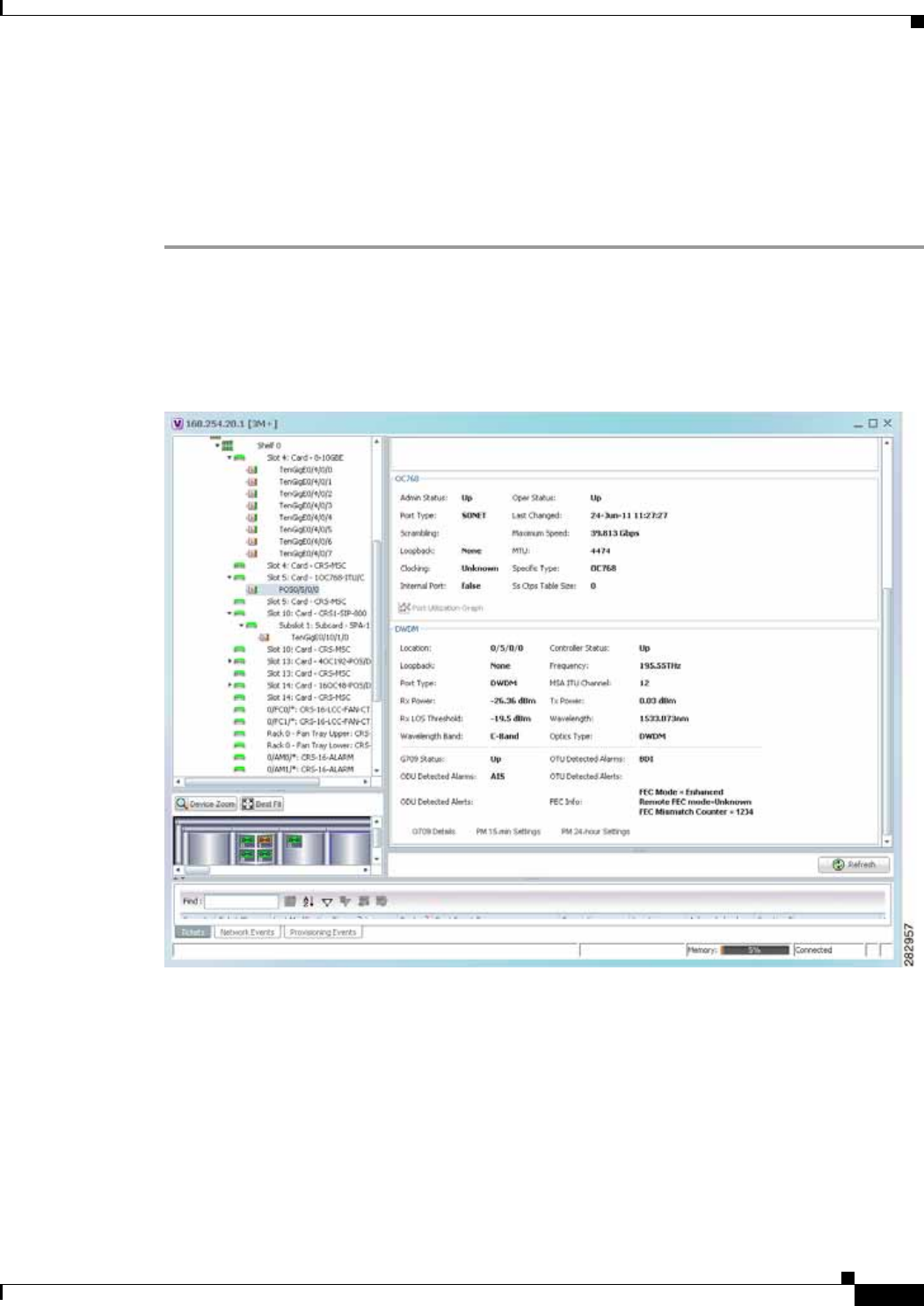
14-3
Cisco Prime Network 4.0 User Guide
OL-29343-01
Chapter 14 Monitoring DWDM Properties Viewing DWDM in Physical Inventory
Viewing DWDM in Physical Inventory
Prime Network Vision enables you to monitor a variety of DWDM properties in physical inventory,
including forward error correction (FEC), G.709 status, and performance monitoring parameters.
To view DWDM properties in physical inventory:
Step 1 In a Prime Network Vision map, double-click the device on which DWDM is configured.
Step 2 In the inventory window, choose Physical Inventory > Chassis and navigate to the interface configured
for DWDM. DWDM details are displayed in the DWDM area in the content pane as shown in
Figure 14-1.
Figure 14-1 DWDM Properties in Physical Inventory

14-4
Cisco Prime Network 4.0 User Guide OL-29343-01
Chapter 14 Monitoring DWDM Properties
Viewing DWDM in Physical Inventory
Table 14-3 describes the information displayed for DWDM.
Table 14-3 DWDM Properties in Physical Inventory
Field Description
Location Physical interface using the format rack/slot/module/port where:
• rack is the chassis number of the rack.
• slot is the physical slot number of the line card.
• module is the module number. A physical layer interface module
(PLIM) is always 0. Shared port adapters (SPAs) are referenced by
their subslot number.
• port is the physical port number of the interface.
Controller Status Status of the controller: Up or Down.
Loopback Whether or not the DWDM controller is configured for loopback mode.
Frequency Frequency of the channel in terahertz.
Port Type The port type. In this case, DWDM.
MSA ITU Channel Multi Source Agreement (MSA) ITU channel number.
Rx Power Actual optical power at the receiving port.
Tx Power Value of the transmit power level.
Rx LOS Threshold Number of optical channel transport unit (OTU) loss of signal (LOS)
alarms. If the receive optical power is less than or equal to this defined
threshold, the optical LOS alarm is raised.
Wavelength Wavelength corresponding to the channel number in nanometers.
Wavelength Band Indicates the wavelength band: C-band or L-band.
Optics Type Indicates the optics type: GE or DWDM.
G709 Properties
G709 Status Whether the G.709 wrapper is enabled or disabled: Up or Down.
OTU Detected Alarms OTU overhead alarms.
ODU Detected Alarms Optical channel data unit (ODU) alarms.
OTU Detected Alerts OTU alerts.
ODU Detected Alerts ODU alerts.
FEC Info Indicates the:
• FEC mode of the controller: Disabled, Enhanced, Standard, or
Unknown.
• FEC mode on the remote device: Disabled, Enhanced, Standard, or
Unknown.
• Number of sync word mismatches found during the tracking phase.
G709 Details Click to view G709 properties. For more information, see Viewing
G.709 Properties, page 14-5.

14-5
Cisco Prime Network 4.0 User Guide
OL-29343-01
Chapter 14 Monitoring DWDM Properties Viewing G.709 Properties
Viewing G.709 Properties
The Telecommunication Standardization Sector (ITU-T) Recommendation G.709 provides a
standardized method for transparently transporting services over optical wavelengths end to end. A
significant component of G.709 is the FEC code that improves performance and extends the distance that
optical signals can span.
To view G.709 properties:
Step 1 In Prime Network Vision, double-click the device on which DWDM is configured.
Step 2 In the inventory window, choose Physical Inventory > Chassis and navigate to the interface configured
for DWDM.
Step 3 In the content pane, click G709 Details.
The G709 Info Properties window is displayed as shown in Figure 14-2 for all Cisco devices except the
Cisco 7600 series devices.
PM 15-min Settings Click to view 15-minute performance monitoring properties. For more
information, see Viewing Performance Monitoring Configuration,
page 14-11.
PM 24-hour Settings Click to view 24-hour performance monitoring properties. For more
information, see Viewing Performance Monitoring Configuration,
page 14-11.
Table 14-3 DWDM Properties in Physical Inventory (continued)
Field Description
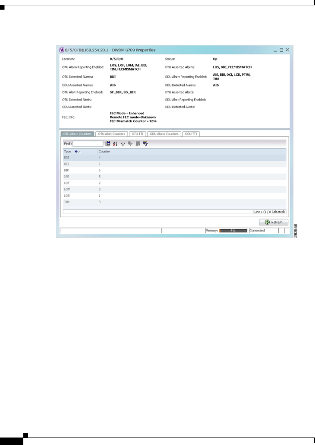
14-6
Cisco Prime Network 4.0 User Guide OL-29343-01
Chapter 14 Monitoring DWDM Properties
Viewing G.709 Properties
Figure 14-2 DWDM G709 Properties Window
Figure 14-3 shows the tabs that are displayed in the G709 Info Properties window for Cisco 7600 series
devices. For Cisco 7600 series devices:
• The ODU Alert Counters tab is displayed.
• The ODU TTI and OTU TTI tabs are not displayed.
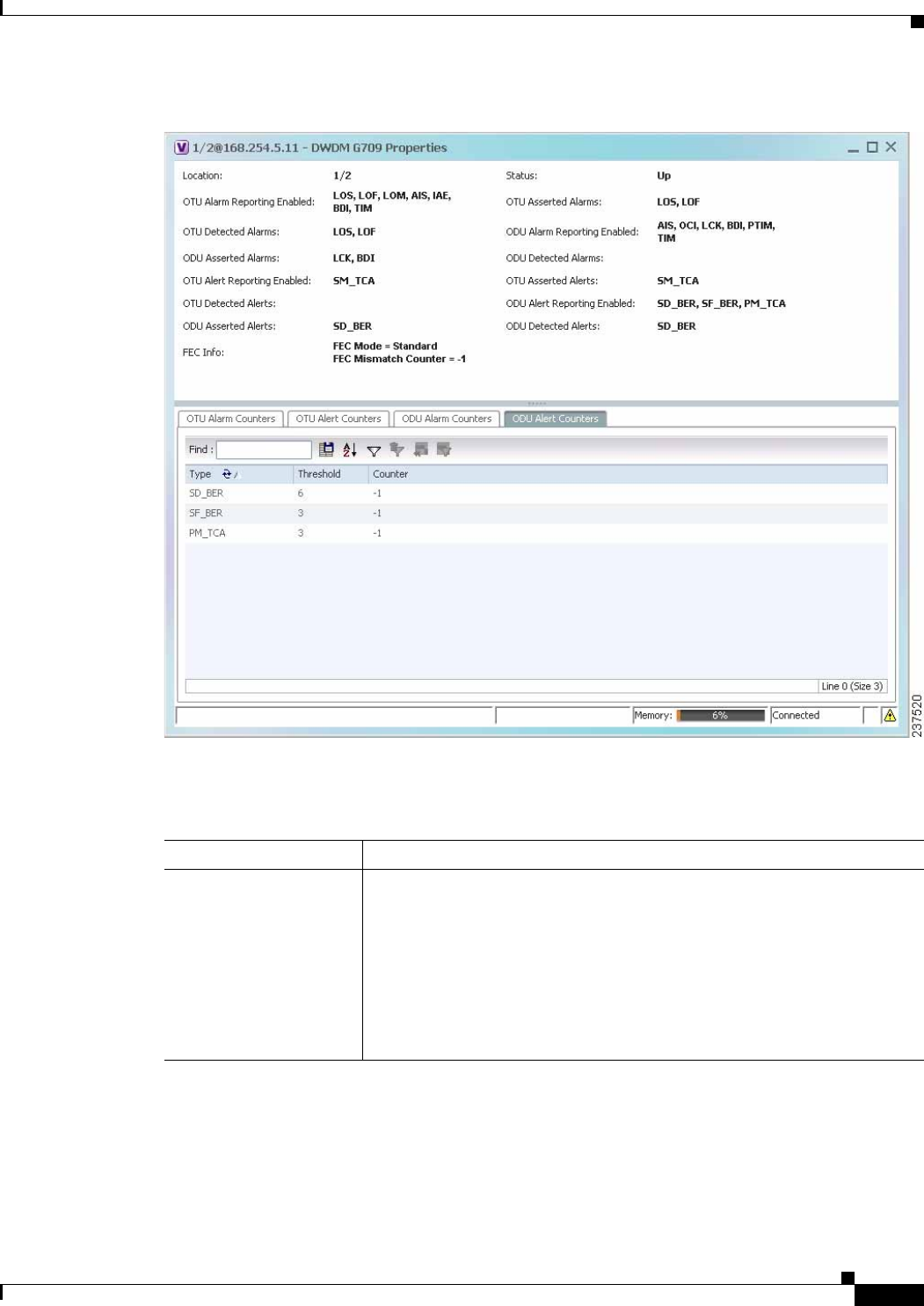
14-7
Cisco Prime Network 4.0 User Guide
OL-29343-01
Chapter 14 Monitoring DWDM Properties Viewing G.709 Properties
Figure 14-3 DWDM G709 Properties Window for Cisco 7600 Series Devices
Table 14-4 describes the fields that are displayed above the tabs in the G709 Info Properties window.
Table 14-4 DWDM G709 Properties Window
Field Description
Location Physical interface using the format rack/slot/module/port where:
• rack is the chassis number of the rack.
• slot is the physical slot number of the line card.
• module is the module number. A physical layer interface module
(PLIM) is always 0. Shared port adapters (SPAs) are referenced by their
subslot number.
• port is the physical port number of the interface.

14-8
Cisco Prime Network 4.0 User Guide OL-29343-01
Chapter 14 Monitoring DWDM Properties
Viewing G.709 Properties
OTU Alarms
OTU Alarm Reporting
Enabled for The types of alarms enabled for reporting:
• AIS—Alarm indication signal (AIS) alarms.
• BDI—Backward defect indication (BDI) alarms.
• BEI—Backward error indication (BEI) alarms.
• BIP—Bit interleaved parity (BIP) alarms.
• FECMISMATCH—FEC mismatch alarms.
• IAE—Incoming alignment error (IAE) alarms.
• LOF—Loss of frame (LOF) alarms.
• LOM—Loss of multiple frames (LOM) alarms.
• LOS—Loss of signal (LOS) alarms.
• TIM—Type identifier mismatch (TIM) alarms.
OTU Asserted Alarms OTU alarms indicated to be reported by the user.
OTU Detected Alarms OTU alarms detected by the hardware.
ODU Alarms
ODU Alarm Reporting
Enabled for The types of ODU alarms enabled for reporting:
• AIS—Incoming SONET AIS error status.
• BDI—Path termination BDI error status.
• BEI—Backward error indication (BEI) error status.
• BIP—Bit interleaved parity (BIP) error status.
• LCK—Upstream connection locked (LCK) error status.
• OCI—Open connection indication (OCI) error status.
• PTIM—Payload TIM error status.
• TIM—Data stream TIM error status.
ODU Asserted Alarms ODU alarms indicated to be reported by the user.
ODU Detected Alarms ODU alarms detected by the hardware.
Table 14-4 DWDM G709 Properties Window (continued)
Field Description

14-9
Cisco Prime Network 4.0 User Guide
OL-29343-01
Chapter 14 Monitoring DWDM Properties Viewing G.709 Properties
Step 4 To view additional G.709 properties, click the required tab. Table 14-5 describes the information
displayed in each tab. The information that is displayed depends on the selected network element.
OTU Alerts
OTU Alert Reporting
Enabled for The types of alerts enabled for reporting:
• SD-BER—Section Monitoring (SM) bit error rate (BER) is in excess
of the signal degradation (SD) BER threshold.
• SF-BER—SM BER is in excess of the signal failure (SF) BER
threshold.
• PM-TCA—Performance monitoring (PM) threshold crossing alert
(TCA).
• SM-TCA—SM threshold crossing alert.
OTU Asserted Alerts OTU alerts indicated to be reported by the user.
OTU Detected Alerts OTU alerts detected by the hardware.
ODU Alerts
ODU Alert Reporting
Enabled for The types of ODU alerts enabled for reporting:
• SD-BER—SM BER is in excess of the SD BER threshold.
• SF-BER—SM BER is in excess of the SF BER threshold.
• PM-TCA—PM threshold crossing alert.
• SM-TCA—SM threshold crossing alert.
ODU Asserted Alerts ODU alerts indicated to be reported by the user.
ODU Detected Alerts ODU alerts detected by the hardware.
Other
FEC Info FEC properties:
• FEC mode for the controller—Disable, Enhanced, Standard, or
Unknown.
• Remote FEC mode—FEC mode on the remote device: Disabled,
Enhanced, Standard, or Unknown.
• FEC mismatch counter—Number of sync word mismatches found
during the tracking phase.
Status G.709 wrapper administrative status: Up or Down.
Table 14-5 G709 Properties Window Tabs
Field Description
OTU Alarm Counters Tab
Type Type of OTU alarm, such as BDI or BEI.
Counter Number of alarms reported for each alarm type.
Table 14-4 DWDM G709 Properties Window (continued)
Field Description

14-10
Cisco Prime Network 4.0 User Guide OL-29343-01
Chapter 14 Monitoring DWDM Properties
Viewing G.709 Properties
OTU Alert Counters Tab
Type Type of OTU alert, such as SD-BER or SF-BER.
Threshold Threshold set for the type of alert.
Counter Number of alerts reported for each alert type. A value of -1 indicates that
no value has been set up.
ODU Alarm Counters Tab
Type Type of ODU alarm, such as AIS or BDI.
Counter Number of alarms reported for each alarm type.
OTU TTI Tab
This tab is not displayed for Cisco 7600 series devices.
Type Type of OTU Trail Trace Identifier (TTI) configured:
• Expected
• Received
• Sent
String Type For each TTI type, the type of string:
• ASCII
• Hexadecimal
TTI String For each TTI type, the specific TTI string configured.
ODU TTI Tab
This tab is not displayed for Cisco 7600 series devices.
Type Type of ODU TTI configured:
• Expected
• Received
• Sent
String Type For each TTI type, the type of string:
• ASCII
• Hexadecimal
TTI String For each TTI type, the specific TTI string configured.
Table 14-5 G709 Properties Window Tabs (continued)
Field Description

14-11
Cisco Prime Network 4.0 User Guide
OL-29343-01
Chapter 14 Monitoring DWDM Properties Viewing Performance Monitoring Configuration
Step 5 To close the G709 Info Properties window, click the upper right corner.
Viewing Performance Monitoring Configuration
Performance monitoring parameters are used to gather, store, set thresholds for, and report performance
data for early detection of problems. Thresholds are used to set error levels for each performance
monitoring parameter. During the accumulation cycle, if the current value of a performance monitoring
parameter reaches or exceeds its corresponding threshold value, a threshold crossing alert (TCA) can be
generated. The TCAs provide early detection of performance degradation.
Prime Network Vision enables you to view the configuration settings for performance monitoring.
Performance monitoring statistics are accumulated on a 15-minute basis, synchronized to the start of
each quarter-hour. They are also accumulated on a daily basis starting at midnight. Historical counts are
maintained for thirty-three 15-minute intervals and two daily intervals.
To view performance monitoring configuration settings:
Step 1 In Prime Network Vision, double-click the device on which DWDM is configured.
Step 2 In the inventory window, choose Physical Inventory > Chassis and navigate to the interface configured
for DWDM.
Step 3 In the content pane, select the performance monitoring configuration settings you want to view:
• To view the performance monitoring 15-minute configuration settings, click PM 15-min Settings.
• To view the performance monitoring 24-hour configuration settings, click PM 24-hour Settings.
The Client DWDM PM Settings Properties window is displayed as shown in Figure 14-4.
ODU Alert Counters Tab
This tab is displayed only for Cisco 7600 series devices.
Type Type of OTU alert, such as SD-BER or SF-BER.
Threshold Threshold set for the type of alert.
Counter Number of alerts reported for each alert type. A value of -1 indicates that
no value has been set up.
Table 14-5 G709 Properties Window Tabs (continued)
Field Description
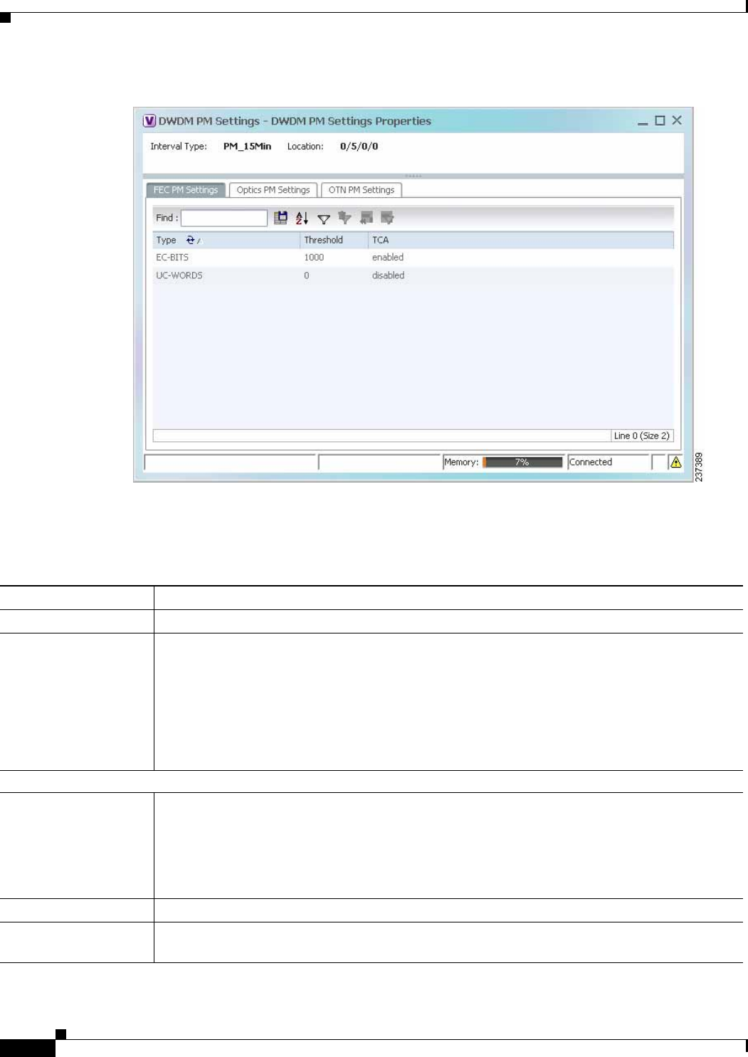
14-12
Cisco Prime Network 4.0 User Guide OL-29343-01
Chapter 14 Monitoring DWDM Properties
Viewing Performance Monitoring Configuration
Figure 14-4 Client DWDM PM Settings Properties Window
Table 14-6 describes the information displayed above the tabs in the Client DWDM PM Settings
Properties window and in each of the tabs.
Table 14-6 Client DWDM PM Settings Properties Window and Tabs
Field Description
Interval Type The performance monitoring interval, either 15 minutes or 24 hours.
Location Physical interface using the format rack/slot/module/port where:
• rack is the chassis number of the rack.
• slot is the physical slot number of the line card.
• module is the module number. A physical layer interface module (PLIM) is always 0. Shared
port adapters (SPAs) are referenced by their subslot number.
• port is the physical port number of the interface.
FEC PM Settings Tab
Type FEC performance monitoring parameter being tracked:
• EC-BITS—The number of bit errors corrected (EC-BITS) in the DWDM trunk line during the
performance monitoring time interval.
• UC-WORDS—The number of uncorrectable words (UC-WORDS) detected in the DWDM
trunk line during the performance monitoring time interval.
Threshold Threshold for the performance monitoring parameter.
TCA Whether TCA generation for the specified parameter on the DWDM controller is enabled or
disabled.

14-13
Cisco Prime Network 4.0 User Guide
OL-29343-01
Chapter 14 Monitoring DWDM Properties Viewing Performance Monitoring Configuration
Optics PM Settings Tab
Type Optics performance monitoring parameter being tracked:
• LBC—Laser bias current.
• OPR—Optical power on the unidirectional port.
• OPT—Transmit optical power in dBm.
Max Threshold Maximum threshold configured for the parameter.
Max TCA If enabled, indicates a TCA is generated if the value of the parameter exceeds the maximum
threshold during the performance monitoring period. If disabled, TCAs are not generated if the
maximum threshold is exceeded.
Min Threshold Minimum threshold configured for the parameter.
Min TCA If enabled, indicates a TCA is generated if the value of the parameter drops below the minimum
threshold during the performance monitoring period. If disabled, TCAs are not generated if the
value drops below the minimum threshold.
Table 14-6 Client DWDM PM Settings Properties Window and Tabs (continued)
Field Description

14-14
Cisco Prime Network 4.0 User Guide OL-29343-01
Chapter 14 Monitoring DWDM Properties
Viewing Performance Monitoring Configuration
OTN PM Settings Tab
Type OTN performance monitoring parameter being tracked:
• bbe-pm-fe—Far-end path monitoring background block errors (BBE-PM). Indicates the
number of background block errors recorded in the optical transport network (OTN) path
during the performance monitoring time interval.
• bbe-pm-ne—Near-end path monitoring background block errors (BBE-PM).
• bbe-sm-fe—Far-end section monitoring background block errors (BBE-SM). Indicates the
number of background block errors recorded in the OTN section during the performance
monitoring time interval.
• bbe-sm-ne—Near-end section monitoring background block errors (BBE-SM).
• bber-pm-fe—Far-end path monitoring background block errors ratio (BBER-PM). Indicates
the background block errors ratio recorded in the OTN path during the performance
monitoring time interval.
• bber-pm-ne—Near-end path monitoring background block errors ratio (BBER-PM).
• bber-sm-fe—Far-end section monitoring background block errors ratio (BBER-SM).
Indicates the background block errors ratio recorded in the OTN section during the
performance monitoring time interval.
• bber-sm-ne—Near-end section monitoring background block errors ratio (BBER-SM)
• es-pm-fe—Far-end path monitoring errored seconds (ES-PM). Indicates the errored seconds
recorded in the OTN path during the performance monitoring time interval.
• es-pm-ne—Near-end path monitoring errored seconds (ES-PM).
• es-sm-fe—Far-end section monitoring errored seconds (ES-SM). Indicates the errored
seconds recorded in the OTN section during the performance monitoring time interval.
• es-sm-ne—Near-end section monitoring errored seconds (ES-SM).
• esr-pm-fe—Far-end path monitoring errored seconds ratio (ESR-PM). Indicates the errored
seconds ratio recorded in the OTN path during the performance monitoring time interval.
• esr-pm-ne—Near-end path monitoring errored seconds ratio (ESR-PM).
• esr-sm-fe—Far-end section monitoring errored seconds ratio (ESR-SM). Indicates the errored
seconds ratio recorded in the OTN section during the performance monitoring time interval.
• esr-sm-ne—Near-end section monitoring errored seconds ratio (ESR-SM).
• fc-pm-fe—Far-end path monitoring failure counts (FC-PM). Indicates the failure counts
recorded in the OTN path during the performance monitoring time interval.
• fc-pm-ne—Near-end path monitoring failure counts (FC-PM).
• fc-sm-fe—Far-end section monitoring failure counts (FC-SM). Indicates the failure counts
recorded in the OTN section during the performance monitoring time interval.
• fc-sm-ne—Near-end section monitoring failure counts (FC-SM).
Table 14-6 Client DWDM PM Settings Properties Window and Tabs (continued)
Field Description

14-15
Cisco Prime Network 4.0 User Guide
OL-29343-01
Chapter 14 Monitoring DWDM Properties Configuring and Viewing DWDM
Configuring and Viewing DWDM
The following commands can be launched from the inventory by right-clicking the appropriate node and
selecting Commands. Before executing any commands, you can preview them and view the results. If
desired, you can also schedule the commands.
The table below lists the configuration commands and the supported network elements. Before executing
any commands, you can preview them and view the results. If desired, you can also schedule the
commands.
For details on the software versions Prime Network supports for thes supported network elements, see
the Cisco Prime Network 4.0 Supported Cisco VNEs. To run the Carrier Grade NAT commands, the
software on the network element must support the Carrier Grade NAT technology.
Type (cont.) • ses-pm-fe—Far-end path monitoring severely errored seconds (SES-PM). Indicates the
severely errored seconds recorded in the OTN path during the performance monitoring time
interval.
• ses-pm-ne—Far-end path monitoring severely errored seconds (SES-PM).
• ses-sm-fe—Far-end section monitoring severely errored seconds (SES-SM). Indicates the
severely errored seconds recorded in the OTN section during the performance monitoring time
interval.
• ses-sm-ne—Near-end section monitoring severely errored seconds (SES-SM).
• sesr-pm-fe—Far-end path monitoring severely errored seconds ratio (SESR-PM). Indicates
the severely errored seconds ratio recorded in the OTN path during the performance
monitoring time interval.
• sesr-pm-ne—Near-end path monitoring severely errored seconds ratio (SESR-PM).
• sesr-sm-fe—Far-end section monitoring severely errored seconds ratio (SESR-SM). Indicates
the severely errored seconds ratio recorded in the OTN section during the performance
monitoring time interval.
• sesr-sm-ne—Near-end section monitoring severely errored seconds ratio (SESR-SM).
• uas-pm-fe—Far-end path monitoring unavailable seconds (UAS-PM). Indicates the
unavailable seconds recorded in the OTN path during the performance monitoring time
interval.
• uas-pm-ne—Near-end path monitoring unavailable seconds (UAS-PM).
• uas-sm-fe—Far-end section monitoring unavailable seconds (UAS-SM). Indicates the
unavailable seconds recorded in the OTN section during the performance monitoring time
interval.
• uas-sm-ne—Near-end section monitoring unavailable seconds (UAS-SM).
Threshold Threshold configured for the parameter.
TCA If enabled, indicates a TCA is generated if the value of the parameter crosses the threshold during
the performance monitoring period. If disabled, TCAs are not generated if the value crosses the
threshold.
Table 14-6 Client DWDM PM Settings Properties Window and Tabs (continued)
Field Description

14-16
Cisco Prime Network 4.0 User Guide OL-29343-01
Chapter 14 Monitoring DWDM Properties
Configuring and Viewing DWDM
Additional commands may be available for your devices. New commands are often provided in Prime
Network Device Packages, which can be downloaded from the Prime Network software download site.
For more information on how to download and install DPs and enable new commands, see the
information on “Adding Additional Device (VNE) support” in the Cisco Prime Network 4.0
Administrator Guide.
Note You might be prompted to enter your device access credentials while executing a command. Once you
have entered them, these credentials will be used for every subsequent execution of a command in the
same GUI client session. If you want to change the credentials, click Edit Credentials. The Edit
Credentials button will not be available for SNMP commands or if the command is scheduled for a later
time.
Command Navigation Input Required and Notes
Controller Data Show > N/A; performed from command launch point
PM History Data PM interval type: 15-min or 24-hour
Interval number
RTPM Counters PM interval type: 15-min or 24-hour
RTPM Threshold PM interval type: 15-min or 24-hour
Wavelength Map N/A; performed from command launch point
IM Trace Details Card location (for example, 0/5/CPU0)
Device Log N/A; performed from command launch point
Counters Clear > N/A; performed from command launch point
Channel Configure > Channel number
Option: Set or reset channel
FEC Mode G.709 FEC mode: Disabled, enhanced, or
standard
G.709 ODU ODU alarm type: ais, bdi, lck, oci, ptim, or tim
Option: Enable or disable alarm type
G.709 OTU OTU alarm type: bdi, fecmismatch, iae, lof,
lom, los, sd-ber, sf-ber, or tim
Option: Enable or disable alarm type

14-17
Cisco Prime Network 4.0 User Guide
OL-29343-01
Chapter 14 Monitoring DWDM Properties Configuring and Viewing DWDM
G.709 TTI Configure > Optical channel unit type: ODU or OTU
TTI type: Expected or sent
TTI string type: ASCII or hex
TTI string
Option: Set or reset TTI string
G.709 Wrapper Option: Disable or enable G.709 wrapper
Laser State Laser state: Switch off or on
Loopback Loopback value: Internal or line
Option: Set or remove
PM FEC Data PM interval type
FEC alarm type:
• Ec-bits—Bit errors corrected (BIEC); the
number of bit errors corrected in the
DWDM trunk line during the performance
monitoring time interval
• Uc-words—Uncorrectable words; the
number of uncorrectable words detected in
the DWDM trunk line during the
performance monitoring time interval
TCA options: Enable or disable TCA generation
Threshold option. Set configures the value on
the device; reset is the default. If you select
blank, the threshold value is not used.
Threshold value
Command Navigation Input Required and Notes

14-18
Cisco Prime Network 4.0 User Guide OL-29343-01
Chapter 14 Monitoring DWDM Properties
Configuring and Viewing DWDM
PM Optics Data Configure > PM interval: 15-min or 24-hour
Optics alarm type:
• lbc—Laser bias current
• opr—Optical power on the unidirectional
port
• opt—Transmit optical power in dBm
Maximum TCA option: Enable or disable
Maximum threshold option: Choosing Set
configures the value on the device; Reset is the
default. If you select blank, the threshold value
is not used.
Maximum threshold
Minimum TCA option: enable or disable
Minimum threshold option: Choosing Set
configures the value on the device; Reset is the
default. If you select blank, the threshold value
is not used.
Minimum threshold
PM OTN Data PM interval: 15-min or 24-hour
OTN alarm type. For a list of types and their
descriptions, see the OTN PN Settings Tab
information in Table 14-6 on page 14-12.
TCA option: Enable or disable
Threshold option: Choosing Set configures the
value on the device; Reset is the default. If you
select blank, the threshold value is not used.
Threshold value
Transmit Power Transmit power in dBm
Option: Set or reset transponder Tx threshold
Rx LOS Threshold Rx LOS threshold value
Option: Set or reset transponder Rx threshold
Command Navigation Input Required and Notes

CHAPTER
15-1
Cisco Prime Network 4.0 User Guide
OL-29343-01
15
Monitoring Ethernet Operations, Administration,
and Maintenance Tool Properties
The following topics describe how you can use Cisco Prime Network Vision (Prime Network Vision) to
monitor Ethernet operations, administration, and maintenance (OAM) tools:
• User Roles Required to View Ethernet OAM Tool Properties, page 15-1
• Ethernet OAM Overview, page 15-2
• Viewing Connectivity Fault Management Properties, page 15-3
• Viewing Ethernet LMI Properties, page 15-10
• Viewing Link OAM Properties, page 15-14
• Configuring CFM, page 15-18
• Configuring E-LMI, page 15-20
• Configuring L-OAM, page 15-21
User Roles Required to View Ethernet OAM Tool Properties
This topic identifies the roles that are required to view Ethernet OAM tool properties. Prime Network
determines whether you are authorized to perform a task as follows:
• For GUI-based tasks (tasks that do not affect elements), authorization is based on the default
permission that is assigned to your user account.
• For element-based tasks (tasks that do affect elements), authorization is based on the default
permission that is assigned to your account. That is, whether the element is in one of your assigned
scopes and whether you meet the minimum security level for that scope.
For more information on user authorization, see the Cisco Prime Network 4.0 Administrator Guide.
The following tables identify the tasks that you can perform:
• Table 15-1 identifies the tasks that you can perform if a selected element is not in one of your
assigned scopes.
• Table 15-2 identifies the tasks that you can perform if a selected element is in one of your assigned
scopes.
By default, users with the Administrator role have access to all managed elements. To change the
Administrator user scope, see the topic on device scopes in the Cisco Prime Network 4.0 Administrator
Guide.

15-2
Cisco Prime Network 4.0 User Guide OL-29343-01
Chapter 15 Monitoring Ethernet Operations, Administration, and Maintenance Tool Properties
Ethernet OAM Overview
Ethernet OAM Overview
Prime Network Vision supports three, interrelated OAM components, including:
• Connectivity Fault Management—Connectivity Fault Management (CFM) is an end-to-end
per-service-instance (per VLAN) Ethernet layer OAM protocol that includes connectivity
monitoring, fault verification, and fault isolation. CFM allows you to manage individual customer
service instances. Ethernet Virtual Connections (EVCs) are the services that are sold to customers
and are designated by service VLAN tags. CFM operates on a per-service-VLAN (or per-EVC)
basis. It lets you know when an EVC fails and provides tools to isolate the failure. See Viewing
Connectivity Fault Management Properties, page 15-3 and Configuring CFM, page 15-18.
Table 15-1 Default Permission/Security Level Required for Viewing Ethernet OAM Tool
Properties - Element Not in User’s Scope
Task Viewer Operator OperatorPlus Configurator Administrator
View CFM properties————X
View Ethernet LMI
properties ————X
View Link OAM
properties ————X
Using CFM Configure
and Enable Commands ——— X X
Using E-LMI Configure
and Enable Commands ——— X X
Using L-OAM
Configuration, Assign,
Enable, and Show
Commands
——— X X
Table 15-2 Default Permission/Security Level Required for Viewing Ethernet OAM Tool
Properties - Element in User’s Scope
Task Viewer Operator OperatorPlus Configurator Administrator
View CFM propertiesXXXXX
View Ethernet LMI
properties XXXXX
Using CFM Configure
and Enable Commands ——— X X
Using E-LMI Configure
and Enable Commands ——— X X
Using L-OAM
Configuration, Assign,
Enable, and Show
Commands
——— X X

15-3
Cisco Prime Network 4.0 User Guide
OL-29343-01
Chapter 15 Monitoring Ethernet Operations, Administration, and Maintenance Tool Properties Viewing Connectivity Fault Management Properties
• Ethernet Local Management Interface—Ethernet Local Management Interface (Ethernet LMI)
operates between the customer edge (CE) and the user-facing provider edge (U-PE) devices.
Ethernet LMI allows you to automatically provision CEs based on EVCs and bandwidth profiles.
See Viewing Ethernet LMI Properties, page 15-10 and Configuring E-LMI, page 15-20.
• Link OAM—Link OAM allows you to monitor and troubleshoot a single Ethernet link. It is an
optional sublayer implemented in the Data Link Layer between the Logical Link Control (LLC) and
MAC sublayers of the Open Systems Interconnect (OSI) model. You can monitor a link for critical
events and, if needed, put a remote device into loopback mode for link testing. Link OAM also
discovers unidirectional links, which are created when one transmission direction fails. See Viewing
Link OAM Properties, page 15-14 and Configuring L-OAM, page 15-21.
Viewing Connectivity Fault Management Properties
CFM allows you to discover and verify end-to-end, Carrier Ethernet PE-to-PE or CE-to-CE paths
through bridges and LANs.
CFM consists of maintenance domains. Maintenance domains are administrative regions used to manage
and administer specific network segments. Maintenance domains are organized in a hierarchy. The
administrator assigns a maintenance level to the domain from 0 (lowest level) to 7 (highest level); the
maintenance level determines the domain’s position within the CFM hierarchy.
CFM maintenance domain boundaries are indicated by maintenance points. A maintenance point is an
interface point that participates within a CFM maintenance domain. Maintenance point types include:
• Maintenance Endpoints—Maintenance endpoints (MEPs) are active CFM elements residing at the
edge of a domain. MEPs can be inward or outward facing. They periodically transmit continuity
check messages and expect to periodically receive similar messages from other MEPs within a
domain. If requested, MEPs can also transmit traceroute and loopback messages. MEPs are
responsible for keeping CFM messages within the boundaries of a maintenance domain.
• Maintenance Intermediate Points—Maintenance intermediate points (MIPs) are passive elements
that catalog information received from MEPs and other MIPs. MIPs only respond to specific CFM
messages such as traceroute and loopback, and they forward those messages within the maintenance
domain.
Note Prime Network Vision does not display information for CFM maintenance endpoints or maintenance
intermediate points for Cisco Viking devices if errors exist in their configurations. An error in the
configuration is indicated by an exclamation point (!) in the CLI output.
For example, if you enter the command show ethernet cfm local maintenance-points, a
configuration error is indicated as follows:
cfm_d100/2 cfm_s100 Te0/2/0/3.110 Up MEP 2100 eb:7a:53!
CFM uses standard Ethernet frames. CFM frames are distinguishable by EtherType and for multicast
messages, by MAC address. CFM frames are sourced, terminated, processed, and relayed by bridges.
Routers support only limited CFM functions.
Bridges that cannot interpret CFM messages forward them as normal data frames. All CFM messages
are confined to a maintenance domain and to an S-VLAN (PE-VLAN or Provider-VLAN). CFM
supports three types of messages:

15-4
Cisco Prime Network 4.0 User Guide OL-29343-01
Chapter 15 Monitoring Ethernet Operations, Administration, and Maintenance Tool Properties
Viewing Connectivity Fault Management Properties
• Continuity check—Multicast heartbeat messages exchanged periodically among MEPs. They allow
MEPs to discover other MEPs within a domain and allow maintenance intermediate points (MIPs)
to discover MEPs. Continuity check messages (CCMs) are confined to a domain and S-VLAN.
• Loopback—Unicast frames that a MEP transmits, at the request of an administrator, to verify
connectivity to a particular maintenance point. A reply to a loopback message indicates whether a
destination is reachable but does not allow hop-by-hop discovery of the path. A loopback message
is similar in concept to an Internet Control Message Protocol (ICMP) Echo (ping) message.
• Traceroute—Multicast frames that a MEP transmits, at the request of an administrator, to track the
path (hop-by-hop) to a destination MEP. They allow the transmitting node to discover vital
connectivity data about the path, and allow the discovery of all MIPs along the path that belong to
the same maintenance domain. For each visible MIP, traceroute messages indicate ingress action,
relay action, and egress action. Traceroute messages are similar in concept to User Datagram
Protocol (UDP) traceroute messages.
From the Logical Inventory tree, you can troubleshoot MEPs using CFM ping, traceroute, MEP status,
and MEP cross-check status. These commands, and all CFM commands, are described in Configuring
CFM, page 15-18.
Prime Network associates alarms with the corresponding MEP or global CFM logical inventory objects.
Prime Network correlates MEP down, MEP up, MEP missing, ETH-AIS, and ETH-RDI events with root
cause alarms and corresponding tickets that exist along the path between the MEP on the reporting
network element and the network element hosting the remote MEP.
To view CFM properties:
Step 1 In Prime Network Vision, double-click the required device for CFM.
Step 2 In the inventory window, choose Logical Inventory > CFM.
Figure 15-1 shows an example of CFM in logical inventory.
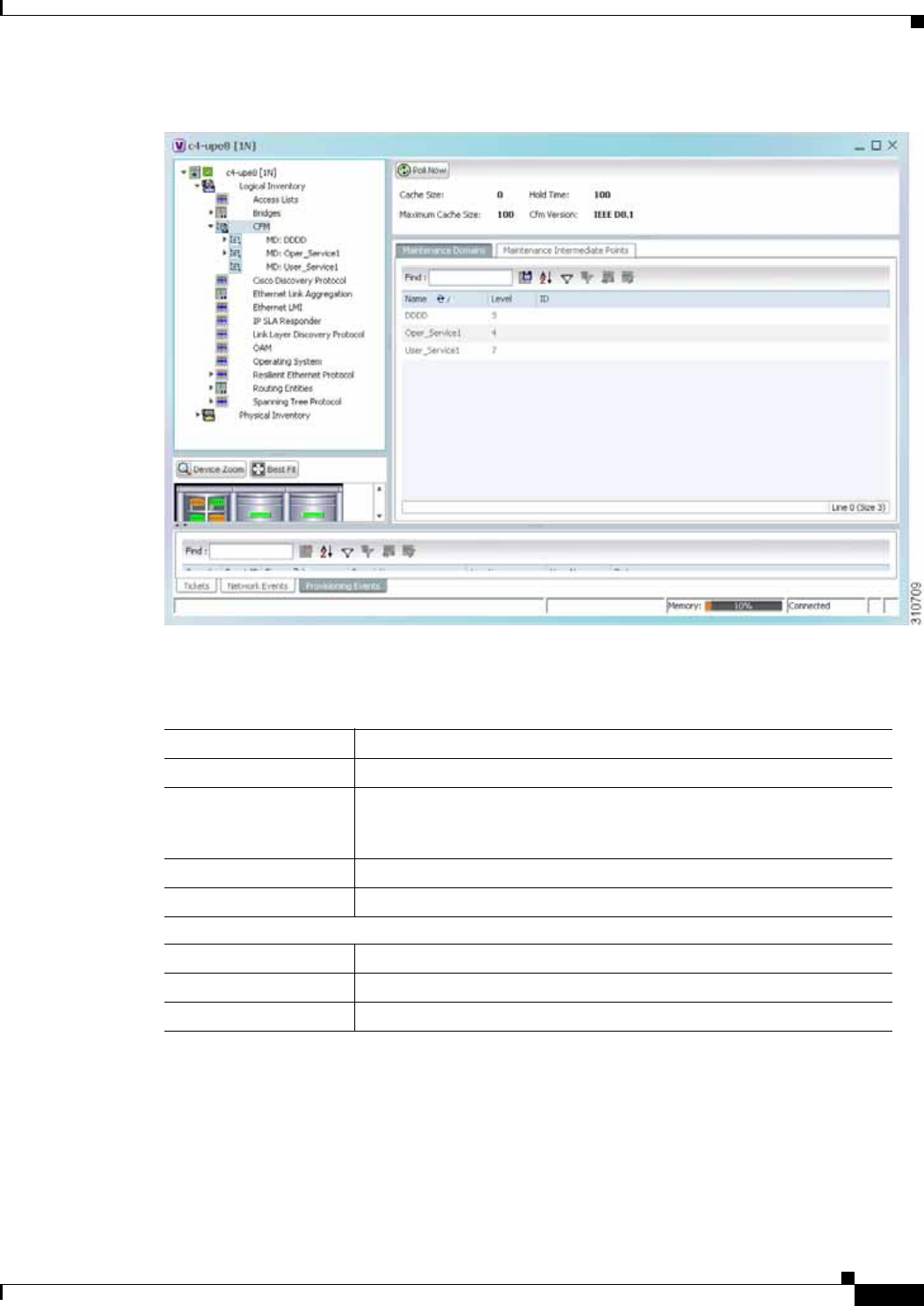
15-5
Cisco Prime Network 4.0 User Guide
OL-29343-01
Chapter 15 Monitoring Ethernet Operations, Administration, and Maintenance Tool Properties Viewing Connectivity Fault Management Properties
Figure 15-1 CFM in Logical Inventory
Table 15-3 describes the information displayed for CFM.
Step 3 Click the Maintenance Intermediate Points tab to view MIP information. See Figure 15-2.
Table 15-3 CFM Properties
Field Description
Cache Size CFM traceroute cache size in number of lines.
Hold Time Configured hold time (in minutes) that is used to indicate to the receiver
the validity of traceroute and loopback messages transmitted by the
device. The default value is 2.5 times the transmit interval.
Maximum Cache Size Maximum CFM traceroute cache size in number of lines.
CFM Version CFM version, such as IEEE D8.1.
Maintenance Domains Table
Name Domain name.
Level Unique level the domain is managed on. Values range from 0 to 7.
ID Optional domain identifier.
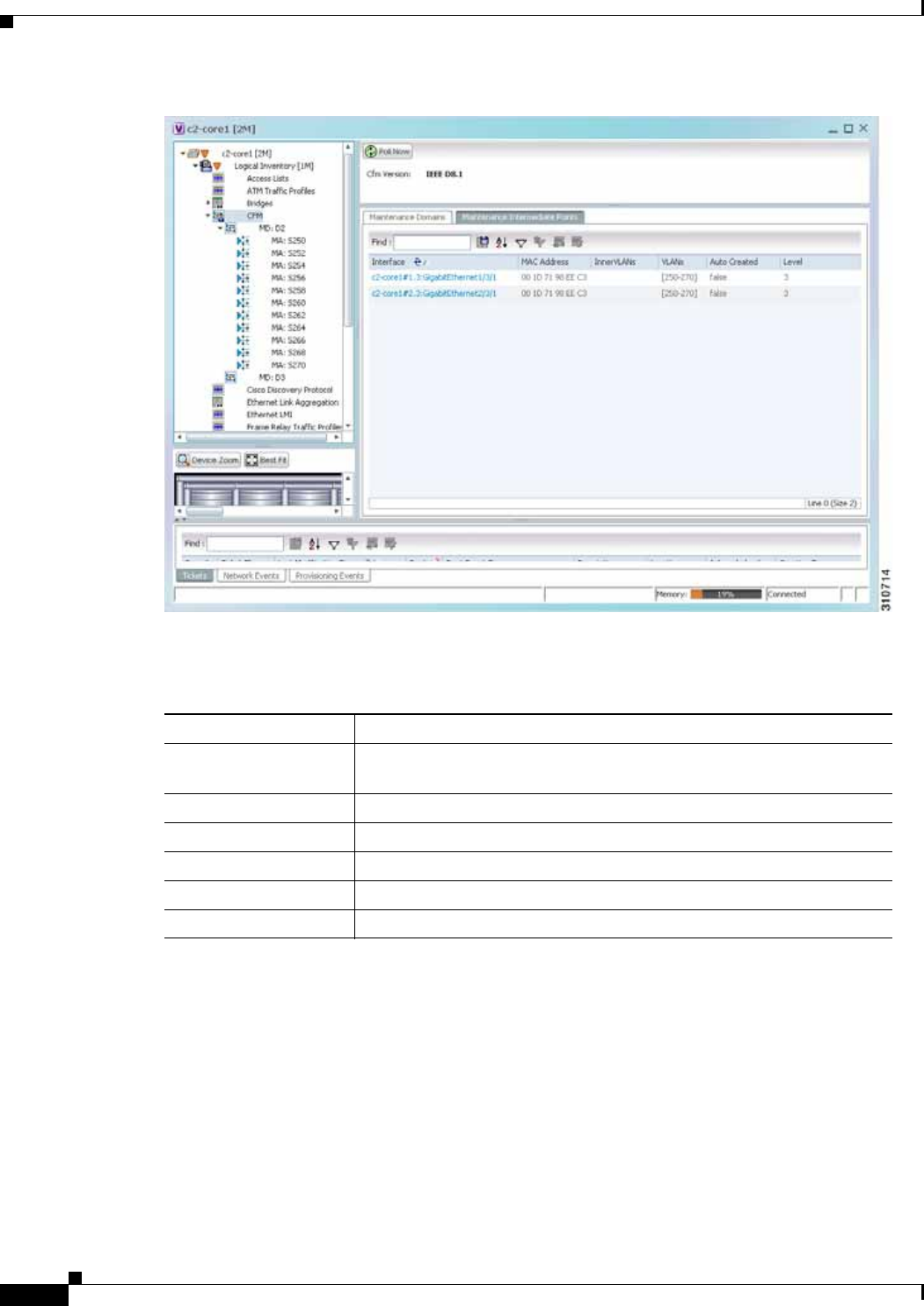
15-6
Cisco Prime Network 4.0 User Guide OL-29343-01
Chapter 15 Monitoring Ethernet Operations, Administration, and Maintenance Tool Properties
Viewing Connectivity Fault Management Properties
Figure 15-2 CFM Maintenance Intermediate Points Tab
Table 15-4 describes the information that is displayed in the Maintenance Intermediate Points table.
Step 4 To view the details of a specific maintenance domain, do one of the following:
• Choose Logical Inventory > CFM > domain.
• Double-click the required entry in the Maintenance Domains table.
Figure 15-3 shows an example of the information displayed for the maintenance domain.
Table 15-4 CFM Maintenance Intermediate Point Properties
Field Description
Interface Interface configured as a MIP, hyperlinked to its entry in physical
inventory.
MAC Address MAC address of the interface.
Inner VLANs Inner VLAN identifiers.
VLANs VLANs associated with the interface.
Auto Created Whether or not the MIP was automatically created: True or False.
Level Unique level the domain is managed on. Values range from 0 to 7.
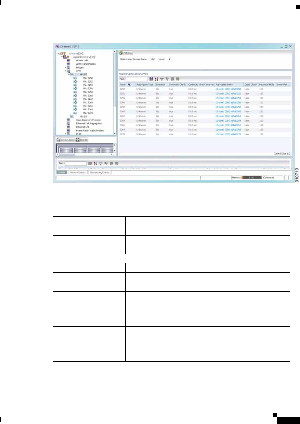
15-7
Cisco Prime Network 4.0 User Guide
OL-29343-01
Chapter 15 Monitoring Ethernet Operations, Administration, and Maintenance Tool Properties Viewing Connectivity Fault Management Properties
Figure 15-3 CFM Maintenance Domain Properties
Table 15-5 describes the information that is displayed for CFM maintenance domains.
Step 5 To view the properties for a maintenance association’s endpoints, do one of the following:
• Choose Logical Inventory > CFM > domain > association.
• In the Maintenance Associations table, double-click the required association.
Table 15-5 CFM Maintenance Domain Properties
Field Description
Maintenance Domain Name Name of the domain.
Level Level at which the domain is managed: 0-7.
ID Optional maintenance domain identifier.
Maintenance Associations Table
Name Name of the maintenance association.
Association Type Maintenance association type.
Direction Direction of the maintenance association: Up or Down.
Continuity Check Whether or not the continuity check is enabled: True or False.
Continuity Check Interval Interval (in seconds) for checking continuity.
Associated Entity Bridge, port, or pseudowire that the maintenance association uses
for CFM. Click the hyperlinked entry to view the item in inventory.
Cross Check Whether or not cross checking is enabled: True or False.
Maximum MEPs Maximum number of maintenance endpoints (MEPs) that can be
configured on the maintenance association.
Inner VLAN Inner VLAN identifier.
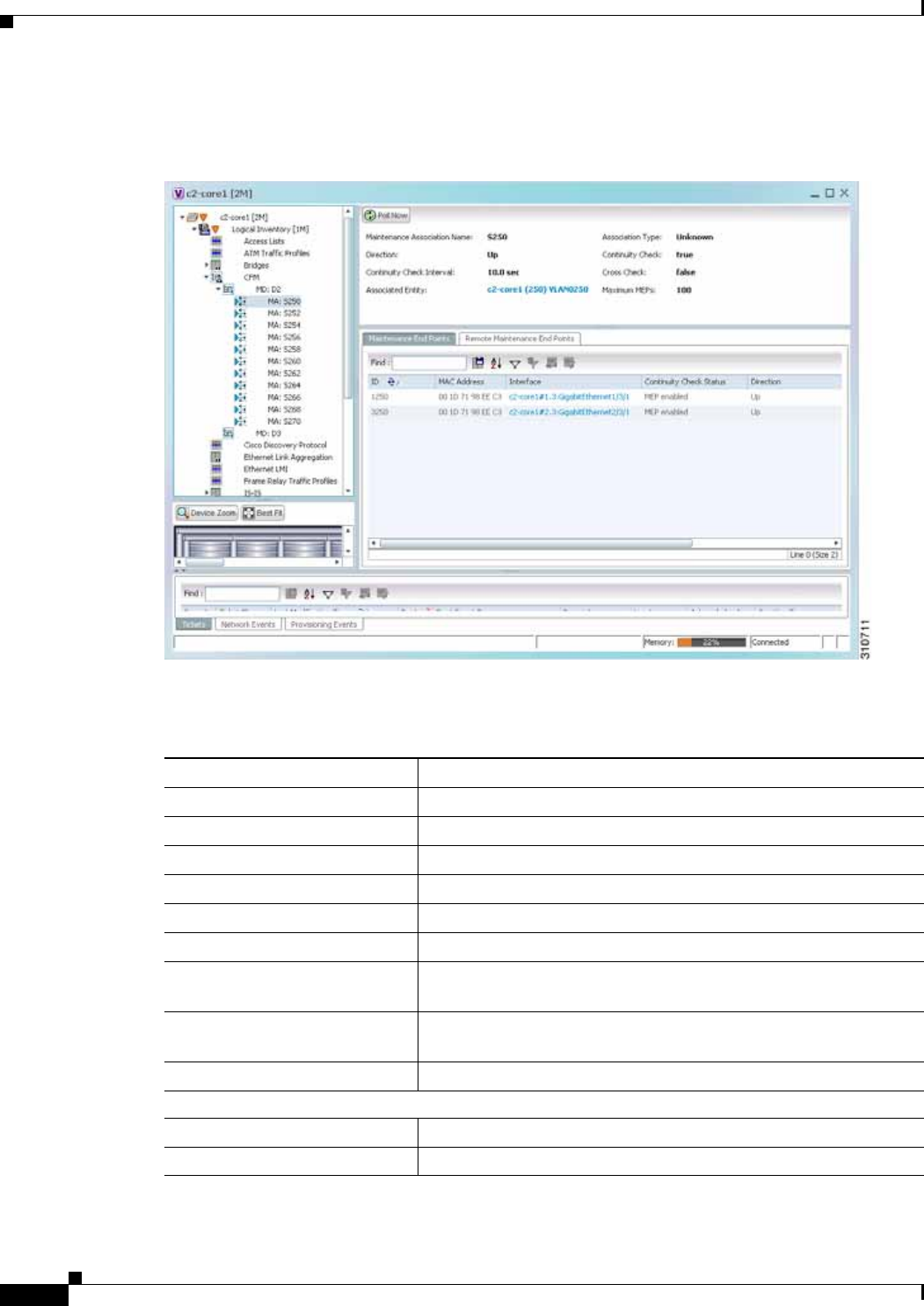
15-8
Cisco Prime Network 4.0 User Guide OL-29343-01
Chapter 15 Monitoring Ethernet Operations, Administration, and Maintenance Tool Properties
Viewing Connectivity Fault Management Properties
Figure 15-4 shows the information displayed for the maintenance association endpoints.
Figure 15-4 CFM Maintenance Association - Endpoint Properties
Table 15-6 describes the information that is displayed for CFM maintenance associations and MIPs.
Table 15-6 CFM Maintenance Association Properties
Field Description
Maintenance Association Name Name of the maintenance association.
Association Type Maintenance association type, such as Bridge Domain.
Direction Direction of the maintenance association: Up or Down.
Continuity Check Whether or not the continuity check is enabled: True or False.
Continuity Check Interval Interval (in seconds) for checking continuity.
Cross Check Whether or not cross checking is enabled: True or False.
Associated Entity Bridge that the maintenance association uses for CFM. Click the
hyperlinked entry to view the bridge in logical inventory.
Maximum MEPs Maximum number of MEPs that can be configured on the
maintenance association.
Inner VLANs Inner VLAN identifiers.
Maintenance End Points Table
ID Local identifier for the MEP.
MAC Address MAC address that identifies the MEP.
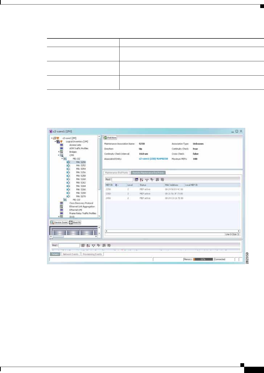
15-9
Cisco Prime Network 4.0 User Guide
OL-29343-01
Chapter 15 Monitoring Ethernet Operations, Administration, and Maintenance Tool Properties Viewing Connectivity Fault Management Properties
Step 6 Click the Remote Maintenance End Points tab to view the information displayed for remote MEPs.
See Figure 15-5.
Figure 15-5 Remote Maintenance End Points Table
Interface Interface on which the MEP is configured, hyperlinked to the
respective EFP, VSI or interface in inventory.
Continuity Check Status CFM continuity check status: MEP Active, MEP Inactive, MEP
Enabled, MEP Disabled, or Unknown.
Direction Direction of traffic on which the MEP is defined: Up, Down, or
Unknown.
Table 15-6 CFM Maintenance Association Properties (continued)
Field Description

15-10
Cisco Prime Network 4.0 User Guide OL-29343-01
Chapter 15 Monitoring Ethernet Operations, Administration, and Maintenance Tool Properties
Viewing Ethernet LMI Properties
Table 15-7 describes the information presented for remote MEPs.
Viewing Ethernet LMI Properties
Ethernet Local Management Interface (E-LMI) is a protocol that operates between the customer edge
(CE) network element and the provider edge (PE) network element. Ethernet LMI is a protocol between
the CE network element and the provider edge (PE) network element. It runs only on the PE-CE UNI
link and notifies the CE of connectivity status and configuration parameters of Ethernet services
available on the CE port. Ethernet LMI interoperates with an OAM protocol, such as CFM, that runs
within the provider network to collect OAM status. CFM runs at the provider maintenance level.
Ethernet LMI relies on the OAM Ethernet Infrastructure (EI) to work with CFM for end-to-end status of
EVCs across CFM domains. E-LMI commands are described in Configuring E-LMI, page 15-20.
The IOS OAM manager streamlines interaction between OAM protocols, and handles the interaction
between CFM and E-LMI. Ethernet LMI interaction with the OAM manager is unidirectional, running
only from the OAM manager to E-LMI on the U-PE side of the switch. Information is exchanged either
as a result of a request from E- LMI or triggered by the OAM manager when it receives notification of
a change from the OAM protocol. Information that is relayed includes the EVC name and availability
status, remote UNI name and status, and remote UNI counts.
To view Ethernet LMI properties:
Step 1 In Prime Network Vision, double-click the device configured for Ethernet LMI.
Step 2 In the inventory window, choose Logical Inventory > Ethernet LMI.
Figure 15-6 shows an example of Ethernet LMI properties in logical inventory.
Table 15-7 CFM Remote Maintenance End Points Table
Field Description
MEP ID Remote MEP identifier.
Level Level at which the remote MEP is managed: 0-7.
Status Status of the remote MEP, such as MEP Active.
MAC Address MAC address of the remote MEP.
Local MEP ID Numeric identifier assigned to the local MEP. Values range from 1 to
8191.
Note If the remote MEP is in Up mode, the remote MEP is not
associated to the local MEP. As a result, the Local MEP ID
column is empty.
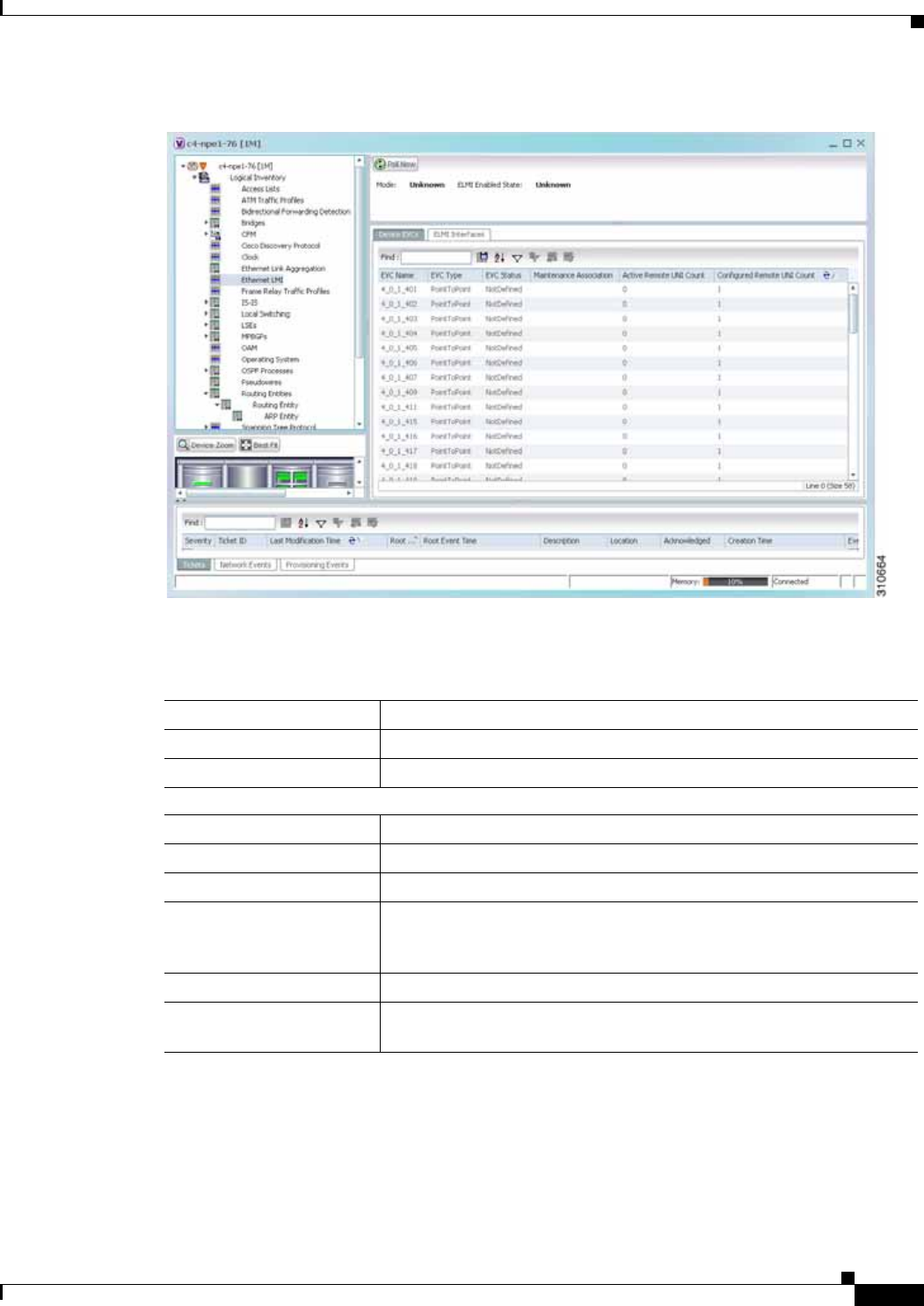
15-11
Cisco Prime Network 4.0 User Guide
OL-29343-01
Chapter 15 Monitoring Ethernet Operations, Administration, and Maintenance Tool Properties Viewing Ethernet LMI Properties
Figure 15-6 Ethernet LMI in Logical Inventory
Table 15-8 describes the information displayed for Ethernet LMI.
Table 15-8 Ethernet LMI Properties in Logical Inventory
Field Description
Globally Enabled Whether or not Ethernet LMI is enabled globally: True or False.
Mode Ethernet LMI mode: CE or PE.
Device EVCs Tab
EVC Name Name of the EVC.
EVC Type Type of EVC: Point-to-point or Multipoint.
EVC Status EVC status: Active, Inactive, Not Defined, or Partially Active.
Maintenance Association Hyperlinked entry to the maintenance association in CFM in logical
inventory. For more information about maintenance associations, see
Table 15-6.
Active Remote UNI Count Number of active remote UNIs.
Configured Remote UNI
Count Number of configured remote UNIs.
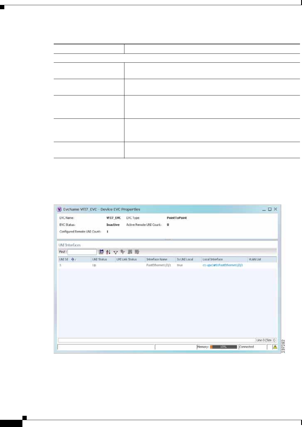
15-12
Cisco Prime Network 4.0 User Guide OL-29343-01
Chapter 15 Monitoring Ethernet Operations, Administration, and Maintenance Tool Properties
Viewing Ethernet LMI Properties
Step 3 To view device EVC properties, double-click an EVC name in the Device EVCs tab.
The Device EVC Properties window is displayed as shown in Figure 15-7.
Figure 15-7 Device EVC Properties Window
Table 15-9 describes the information displayed in the Device EVC Properties window.
ELMI Interfaces Tab
Interface Name Hyperlinked entry to the interface in physical inventory. For more
information, see Step 4 in this procedure.
T391 Frequency at which the customer equipment sends status inquiries. The
range is 5-30 seconds, with a default of 10 seconds.
T392 Frequency at which the metro Ethernet network verifies that status
enquiries have been received. The range is 5-30 seconds, with a default
of 15 seconds. A value of 0 (zero) indicates the timer is disabled.
N391 Frequency at which the customer equipment polls the status of the UNI
and all EVCs. The range is 1-65000 seconds, with a default of 360
seconds.
N393 Error count for the metro Ethernet network. The range is 1-10, with a
default of 4.
Table 15-8 Ethernet LMI Properties in Logical Inventory (continued)
Field Description

15-13
Cisco Prime Network 4.0 User Guide
OL-29343-01
Chapter 15 Monitoring Ethernet Operations, Administration, and Maintenance Tool Properties Viewing Ethernet LMI Properties
Step 4 To view properties for an Ethernet LMI interface in physical interface, click the required interface name
in the ELMI Interfaces table.
Table 15-10 describes the information displayed in the UNI Properties area in physical inventory.
Table 15-9 Device EVC Properties in Logical Inventory
Field Description
EVC Name Name of the EVC.
EVC Type Type of EVC: Point-to-point or Multipoint.
EVC Status EVC status: Active, Inactive, Not Defined, or Partially Active.
Maintenance Association Hyperlinked entry to the maintenance association in CFM in logical
inventory. For more information about maintenance associations, see
Table 15-6.
Active Remote UNI Count Number of active remote UNIs.
Configured Remote UNI
Count
Number of configured remote UNIs.
UNI Interfaces Table
UNI Id UNI identifier.
UNI Status Status of the UNI: Up or Down.
LMI Link Status Status of the LMI link: Up or Down.
Interface Name Interface on which UNI is configured.
Is UNI Local Whether or not UNI is local: True or False.
Local Interface Hyperlinked entry to the interface in physical inventory.
VLAN List Name of the VLAN associated with the UNI interface.
Table 15-10 Ethernet LMI UNI Properties in Physical Inventory
Field Description
Service Multiplexing Enabled Whether or not the interface is configured for UNI
multiplexing: True or False.
Bundling Enabled Whether or not the interface is configured for UNI bundling:
True or False.
UNI Id UNI identifier.
Bundling Type Type of bundling applied: All-to-One or None.
This field appears only when a bundling type is set.

15-14
Cisco Prime Network 4.0 User Guide OL-29343-01
Chapter 15 Monitoring Ethernet Operations, Administration, and Maintenance Tool Properties
Viewing Link OAM Properties
Viewing Link OAM Properties
Link OAM is an optional sublayer implemented in the OSI Data Link Layer between the Logical Link
Control and MAC sublayers. Link (802.3AH) OAM (L-OAM) can be implemented on any full-duplex
point-to-point or emulated point-to-point Ethernet link.
The frames (OAM Protocol Data Units [OAMPDUs]) cannot propagate beyond a single hop within an
Ethernet network and have modest bandwidth requirements (frame transmission rate is limited to a
maximum of 10 frames per second).
Link OAM processes include:
• Discovery—Discovery is the first Link OAM process. During discovery, Link OAM identifies the
devices at each end of the link and learns their OAM capabilities.
• Link monitoring—Link OAM link monitoring includes:
–
Monitoring links and issuing notifications when error thresholds are exceeded or faults occur.
–
Collecting statistics on the number of frame errors (or percent of frames that have errors) and
the number of coding symbol errors.
• Remote MIB Variable Retrieval—Provides 802.3ah MIB polling and response (but not writing).
• Remote Failure indication—Informs peers when a received path goes down. Because link
connectivity faults caused by slowly deteriorating quality are difficult to detect, Link OAM
communicates such failure conditions to its peer using OAMPDU flags. The failure conditions that
can be communicated are a loss of signal in one direction on the link, an unrecoverable error (such
as a power failure), or some other critical event.
• Remote Loopback—Puts the peer device in (near-end) intrusive loopback mode using the OAMPDU
loopback control. Statistics can be collected during the link testing. In loopback mode, every frame
received is transmitted back unchanged on the same port (except for OAMPDUs, which are needed
to maintain the OAM session). Loopback mode helps ensure the quality of links during installation
or troubleshooting. Loopback mode can be configured so that the service provider device can put
the customer device into loopback mode, but the customer device cannot put the service provider
device in loopback mode.
Prime Network Vision supports topology discovery based on Link OAM information and enables you to
view Link OAM properties. You can also configure L-OAM using the commands described in
Configuring L-OAM, page 15-21.
For information on CFM and Ethernet LMI, see Viewing Connectivity Fault Management Properties,
page 15-3 and Viewing Ethernet LMI Properties, page 15-10.
To view Link OAM properties:
Step 1 In Prime Network Vision, double-click the device configured for Link OAM.
Step 2 In the inventory window, choose Logical Inventory > OAM.
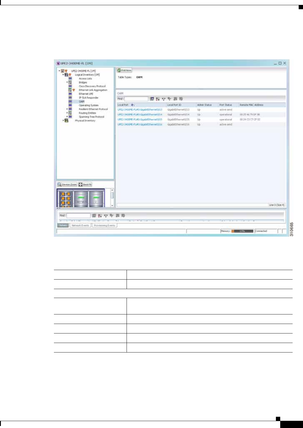
15-15
Cisco Prime Network 4.0 User Guide
OL-29343-01
Chapter 15 Monitoring Ethernet Operations, Administration, and Maintenance Tool Properties Viewing Link OAM Properties
Figure 15-8 shows an example of Link OAM properties in logical inventory.
Figure 15-8 Link OAM Properties in Logical Inventory
Table 15-11 describes the information displayed for Link OAM.
Table 15-11 Link OAM Properties in Logical Inventory
Field Description
Table Types Type of table. In this case, it is OAM.
OAM Table
Local Port Name of the OAM-supported interface, hyperlinked to the location
in physical inventory.
Local Port ID Local port identifier, such as FastEthernet1/0/9.
Admin Status Administrative status of the interface.
Port Status Status of the port.
Remote MAC Address Remote client MAC address.

15-16
Cisco Prime Network 4.0 User Guide OL-29343-01
Chapter 15 Monitoring Ethernet Operations, Administration, and Maintenance Tool Properties
Viewing Link OAM Properties
Step 3 To view detailed information about an entry in the table, double-click the required entry.
The Link OAM Data Properties window is displayed as shown in Figure 15-9.
Figure 15-9 Link OAM Data Properties Window
Table 15-12 describes the information that is displayed in the Link OAM Data Properties window.
Table 15-12 Link OAM Data Properties Window
Field Description
Local Interface
Local Port Name of the OAM-supported interface, hyperlinked to the location
in physical inventory.
Local Port ID Local port identifier.
Admin Status Administrative status of the interface: Up or Down.
Port Status Status of the port, such as Operational.
PDU Max Rate (Frames/sec) Maximum transmission rate measured by the number of OAM
PDUs per second; for example, 10 packets per second.
PDU Min Rate
(Seconds/frame) Minimum transmission rated measured by the number of seconds
required for one OAM PDU; for example, 1 packet per 2 seconds.
Link Timeout Number of seconds of inactivity on a link before the link is dropped.
High Threshold Action Action that occurs when the high threshold for an error is exceeded.
Link Fault Action Action that occurs when the signal is lost.

15-17
Cisco Prime Network 4.0 User Guide
OL-29343-01
Chapter 15 Monitoring Ethernet Operations, Administration, and Maintenance Tool Properties Viewing Link OAM Properties
Step 4 To view Link OAM status in physical inventory, choose Physical Inventory > chassis > slot > interface.
The Link OAM administrative status is displayed as shown in Figure 15-10.
Dying Gasp Action Action that occurs when an unrecoverable condition is encountered.
Critical Event Action Action that occurs when an unspecified vendor-specific critical
event occurs.
Mode Mode of the interface: Active or Passive.
Unidirection Status of unidirectional Ethernet on the local interface: Supported
or Not supported.
Link Monitor Status of link monitoring on the local interface: Supported or Not
supported.
Remote Loopback Status of remote loopback on the local interface: Supported or Not
supported.
Loopback Status Status of loopback on the local interface: Supported or No
loopback.
Remote Client
MAC Address MAC address for the remote client.
Vendor Vendor of the remote client.
Mode Mode of the remote client: Active or Passive.
Unidirection Status of unidirectional Ethernet on the remote client interface:
Supported or Not supported.
Link Monitor Status of link monitoring on the remote client interface: Supported
or Not supported.
Remote Loopback Status of loopback on the remote client interface: Supported or Not
supported.
Table 15-12 Link OAM Data Properties Window (continued)
Field Description
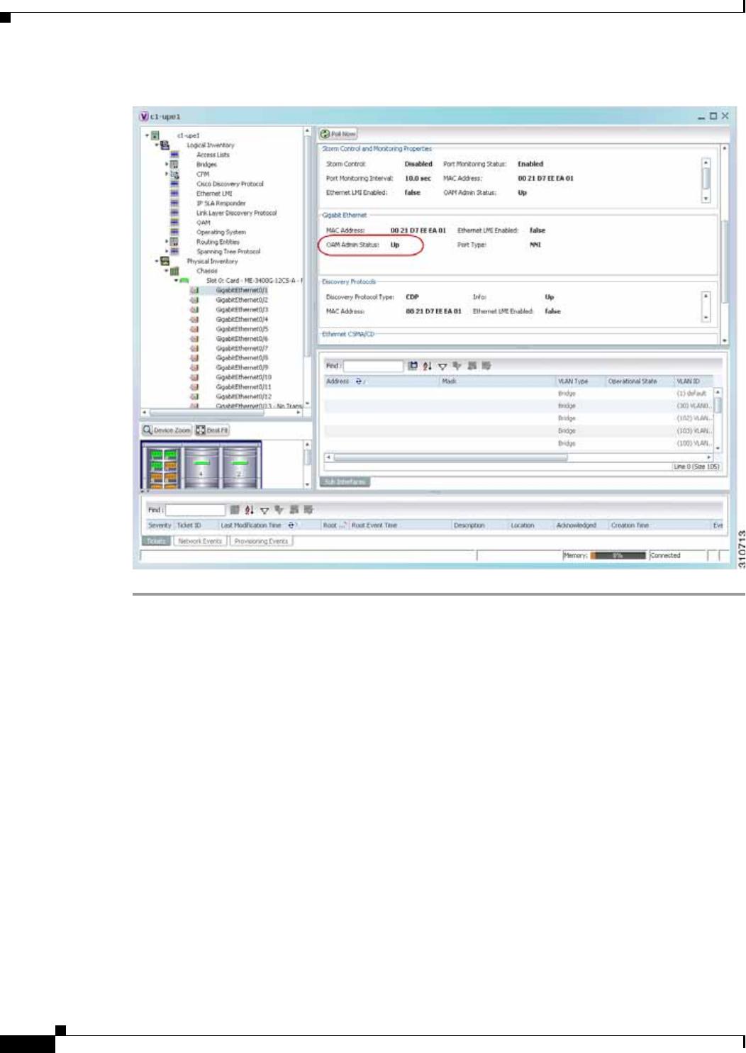
15-18
Cisco Prime Network 4.0 User Guide OL-29343-01
Chapter 15 Monitoring Ethernet Operations, Administration, and Maintenance Tool Properties
Configuring CFM
Figure 15-10 Link OAM Administrative Status in Physical Inventory
Configuring CFM
CFM provides capabilities for detecting, verifying, and isolating connectivity failures in networks with
bridges operated by multiple independent organizations, each with restricted management access to each
other's equipment.
The CFM commands can be launched from the inventory by right-clicking a CFM node and selecting
Commands. Unless otherwise noted, all of the following commands are launched by right-clicking the
device and choosing Commands > Configure > Cisco. You can navigate from the MEP logical
inventory to the interface or port channel on which the MEP is configured.
To run the these commands, the software on the network element must support the technology. Before
executing any commands, you can preview them and view the results. If desired, you can also schedule
the commands. For details on the software versions Prime Network supports for the listed supported
network elements, see Cisco Prime Network 4.0 Supported Cisco VNEs.
Additional commands may be available for your devices. New commands are often provided in Prime
Network Device Packages, which can be downloaded from the Prime Network software download site.
For more information on how to download and install DPs and enable new commands, see the
information on “Adding Additional Device (VNE) support” in the Cisco Prime Network 4.0
Administrator Guide.

15-19
Cisco Prime Network 4.0 User Guide
OL-29343-01
Chapter 15 Monitoring Ethernet Operations, Administration, and Maintenance Tool Properties Configuring CFM
Note You might be prompted to enter your device access credentials while executing a command. Once you
have entered them, these credentials will be used for every subsequent execution of a command in the
same GUI client session. If you want to change the credentials, click Edit Credentials. The Edit
Credentials button will not be available for SNMP commands or if the command is scheduled for a later
time.
Command Description
Maintenance
Domain > Configure CFM
Maintenance Domain
A maintenance domain is a management space for the purpose of
managing and administering a network. A single entity owns and
operates a domain and is defined by the set of ports internal to it and
at its boundary. Each maintenance domain can contain any number
of maintenance associations. Each maintenance association
identifies a service that can be uniquely identified within the
maintenance domain. The CFM protocol runs within a particular
maintenance association.
Using this command, assign a unique maintenance level to each
domain and a maintenance endpoint archived hold time. Maintenace
level defines the hierarchical relationship among domains and MEP
Archive Hold time acts as a demarcation point on an interface that
participates in CFM.
Global
Parameters > Configure CFM
Global Parameters
Enable CFM globally for a network element. Using this command
you can configure the device to transmit traceroute and loopback
messages with a hold-time value that indicates the validity of the
messages.
Enable > Cisco >Continuity
Check > Configure CFM
Continuity Check
Enable > Cisco >Continuity
Check > Enable CFM
Continuity Check
Enable continuity check parameters on the specified domain,
service1, bridge group, and bridge domain names.
MIP > Configure CFM MIP The Configure CFM MIP command configures an operator-level
maintenance intermediate point (MIP) for the domain-level ID.
If the port on which a MIP is configured is blocked by
Spanning-Tree Protocol (STP), the MIP cannot receive CFM
messages or relay them toward the relay function side. The MIP can,
however, receive and respond to CFM messages from the wire.
A MIP has only one level associated with it, and the command-line
interface (CLI) does not allow you to configure a MIP for a domain
that does not exist.
Note This command is not supported on the Cisco Carrier Packet
Transport (CPT) System.
Service ID > Configure CFM
Service ID Use the Configure CFM Service ID command to configure the CFM
service ID.

15-20
Cisco Prime Network 4.0 User Guide OL-29343-01
Chapter 15 Monitoring Ethernet Operations, Administration, and Maintenance Tool Properties
Configuring E-LMI
Configuring E-LMI
E-LMI notifies the CE of connectivity status and configuration parameters of Ethernet services available
on the CE port.
The following commands can be launched from the inventory by right-clicking an E-LMI node and
selecting Commands. Before executing any commands, you can preview them and view the results. If
desired, you can also schedule the commands. The table below lists the Ethernet LMI commands and the
supported network elements.
Additional commands may be available for your devices. New commands are often provided in Prime
Network Device Packages, which can be downloaded from the Prime Network software download site.
For more information on how to download and install DPs and enable new commands, see the
information on “Adding Additional Device (VNE) support” in the Cisco Prime Network 4.0
Administrator Guide.
To run the these commands, the software on the network element must support the technology. Before
executing any commands, you can preview them and view the results. If desired, you can also schedule
the commands. For details on the software versions Prime Network supports for the listed supported
network elements, see Cisco Prime Network 4.0 Supported Cisco VNEs.
Note You might be prompted to enter your device access credentials while executing a command. Once you
have entered them, these credentials will be used for every subsequent execution of a command in the
same GUI client session. If you want to change the credentials, click Edit Credentials. The Edit
Credentials button will not be available for SNMP commands or if the command is scheduled for a later
time.
MEP > Configure CFM MEP Use this command to configure maintenance endpoints (MEPs),
which have the following characteristics:
• Per-maintenance domain (level) and service (S-VLAN or EVC)
• At the edge of a domain, define the boundary
• Within the bounds of a maintenance domain, confine CFM
messages
• When configured to do so, proactively transmit CFM continuity
check messages (CCMs)
• At the request of an administrator, transmit traceroute and
loopback messages
Note This command is not supported on the Cisco Carrier Packet
Transport (CPT) System.
Enable > Cisco > SNMP
Server Traps > Enable CFM
SNMP Server Traps
Enables Ethernet CFM continuity check traps and Ethernet CFM
cross-check traps
1. Applicable for Cisco ASR 9000 series that run on Cisco IOS XR software.
Command Description

15-21
Cisco Prime Network 4.0 User Guide
OL-29343-01
Chapter 15 Monitoring Ethernet Operations, Administration, and Maintenance Tool Properties Configuring L-OAM
Configuring L-OAM
L-OAM commands monitors and troubleshoots a single Ethernet link. The following commands can be
launched from the inventory by right-clicking a L-OAM node and selecting Commands. Before
executing any commands, you can preview them and view the results. If desired, you can also schedule
the commands. The table below lists the L-OAM commands.
To run the these commands, the software on the network element must support the technology. Before
executing any commands, you can preview them and view the results. If desired, you can also schedule
the commands. For details on the software versions Prime Network supports for the listed supported
network elements, see Cisco Prime Network 4.0 Supported Cisco VNEs.
Additional commands may be available for your devices. New commands are often provided in Prime
Network Device Packages, which can be downloaded from the Prime Network software download site.
For more information on how to download and install DPs and enable new commands, see the
information on “Adding Additional Device (VNE) support” in the Cisco Prime Network 4.0
Administrator Guide.
Note You might be prompted to enter your device access credentials while executing a command. Once you
have entered them, these credentials will be used for every subsequent execution of a command in the
same GUI client session. If you want to change the credentials, click Edit Credentials. The Edit
Credentials button will not be available for SNMP commands or if the command is scheduled for a later
time.
Command Description
Enable > Global E-LMI Enable Ethernet LMI globally.
Note Not supported on Cisco IOS XR.
Enable On Interface If E-LMI is disabled globally, you can use this
command to enable E-LMI on specific interfaces.
Configure MultiPoint To MultiPoint or
Point To Point EVC UNI count indicates the range of the Unified network
interface(UNI) is 2 to 1024; the default is 2. If you
enter a value of 2, you have the option to select
point-to-multipoint service. If you configure a value of
3 or greater, the service is point-to-multipoint.
Configure UNI in an Interface
Configure Service Instance Vlan Id on
Interface Specify the service interface ID (Per-interface Ethernet
service instance identifier that does not map to a
VLAN).
Command Description
Assign Template on Interface Assign template name
Configure MultiPoint To MultiPoint
or Point To Point EVC Configure OAM (L-OAM) on any full-duplex
point-to-point or emulated point-to-point Ethernet link.
Enable OAM on Interface
Disable OAM on Interface
Enable or disable OAM on the specified interface.

15-22
Cisco Prime Network 4.0 User Guide OL-29343-01
Chapter 15 Monitoring Ethernet Operations, Administration, and Maintenance Tool Properties
Configuring L-OAM
Enable E-LMI On Interface Interface name (if E-LMI is disabled globally, you can use
this command to enable E-LMI on specific interfaces)
Configure OAM Parameter on
Interface Configure OAM parameters, like maximum and minimum
transmission rate of OAM PDU , OAM client mode and
remote loopback ability on an interface.
Start Remote Loopback
Stop Remote Loopback
Specify the local interface name on which the remote
loopback should be started and stopped.
Command Description

CHAPTER
16-1
Cisco Prime Network 4.0 User Guide
OL-29343-01
16
Monitoring Y.1731 IPSLA Configuration
The following topics provide an overview of the Y.1731 technology and describe how to view and
monitor Y.1731 configurations in Prime Network Vision:
• Y.1731 Technology: Overview, page 16-1
• User Roles Required to Work with Y.1731 Probes, page 16-2
• Working with Y.1731 IPSLA Configurations, page 16-2
Y.1731 Technology: Overview
Y.1731 is an ITU-T recommendation that provides mechanisms for service-level Operation,
Administration, and Maintenance (OAM) functionality in Ethernet networks. It covers mechanisms for
Fault and Performance Management. Performance Management is the most sought-after functionality in
this standard.
In Prime Network, devices that are configured using Y.1731 are detected, scanned for configurations,
and monitored. A device configured using Y.1731 has probes, which are root objects or containers that
hold single or multiple instances of Service Level Agreement (SLA) probes configured by the user.
In Prime Network, the Y.1731 technology is supported on the Cisco Aggregation Service Router (ASR)
9000 and Cisco Carrier Packet Transport (CPT) network elements.
Y.1731 Performance Management Mechanisms
The OAM functions for performance monitoring according to Y.1731 allow measurement of the
following performance parameters.
• Frame Loss Ratio—Expressed as a percentage. This ratio is defined as the number of frames not
delivered divided by the total number of frames during a time interval.
• Frame Delay—A one-way delay for a frame, where one-way frame delay is defined as the time
elapsed since the start of transmission of the first bit of the frame by a source node until the reception
of the last bit of the same frame by the destination node.
• Frame Delay Variation—The measure of the variations in the frame delay between a pair of service
frames. The service frames belong to the same CoS (Class of Service) instance on a point-to-point
Ethernet (ETH) connection or multipoint ETH connectivity.
• Throughput—The average rate of successful traffic delivery over a communication channel.
Typically used under test conditions, such as out-of service tests, when there is no traffic for the
tested Ethernet connection.

16-2
Cisco Prime Network 4.0 User Guide OL-29343-01
Chapter 16 Monitoring Y.1731 IPSLA Configuration
User Roles Required to Work with Y.1731 Probes
User Roles Required to Work with Y.1731 Probes
This topic identifies the roles that are required to work with Y.1731 probes. Prime Network determines
whether you are authorized to perform a task as follows:
• For GUI-based tasks (tasks that do not affect elements), authorization is based on the default
permission that is assigned to your user account.
• For element-based tasks (tasks that do affect elements), authorization is based on the default
permission that is assigned to your account. That is, whether the element is in one of your assigned
scopes and whether you meet the minimum security level for that scope.
For more information on user authorization, see the topic on device scopes in the Cisco Prime Network
4.0 Administrator Guide.
Working with Y.1731 IPSLA Configurations
This topic contains the following sections:
• Viewing Y.1731 Probe Properties, page 16-2
• Configuring Y.1731 Probes, page 16-4
Viewing Y.1731 Probe Properties
To view Y.1731 probes and their properties for a device:
Step 1 Right-click on the device and choose Inventory.
Step 2 In the Inventory window, choose Logical Inventory > Probes > Y1731 Probes. A list of Y.1731 probes
is displayed in the Y.1731 Probes content pane as shown in Figure 16-1.
Table 16-1 Default Permission/Security Level Required for Y.1731 Probes
Task Viewer Operator OperatorPlus Configurator Administrator
View the Y.1731 probe properties XX X X X
Configure Y.1731 probes — — — XX
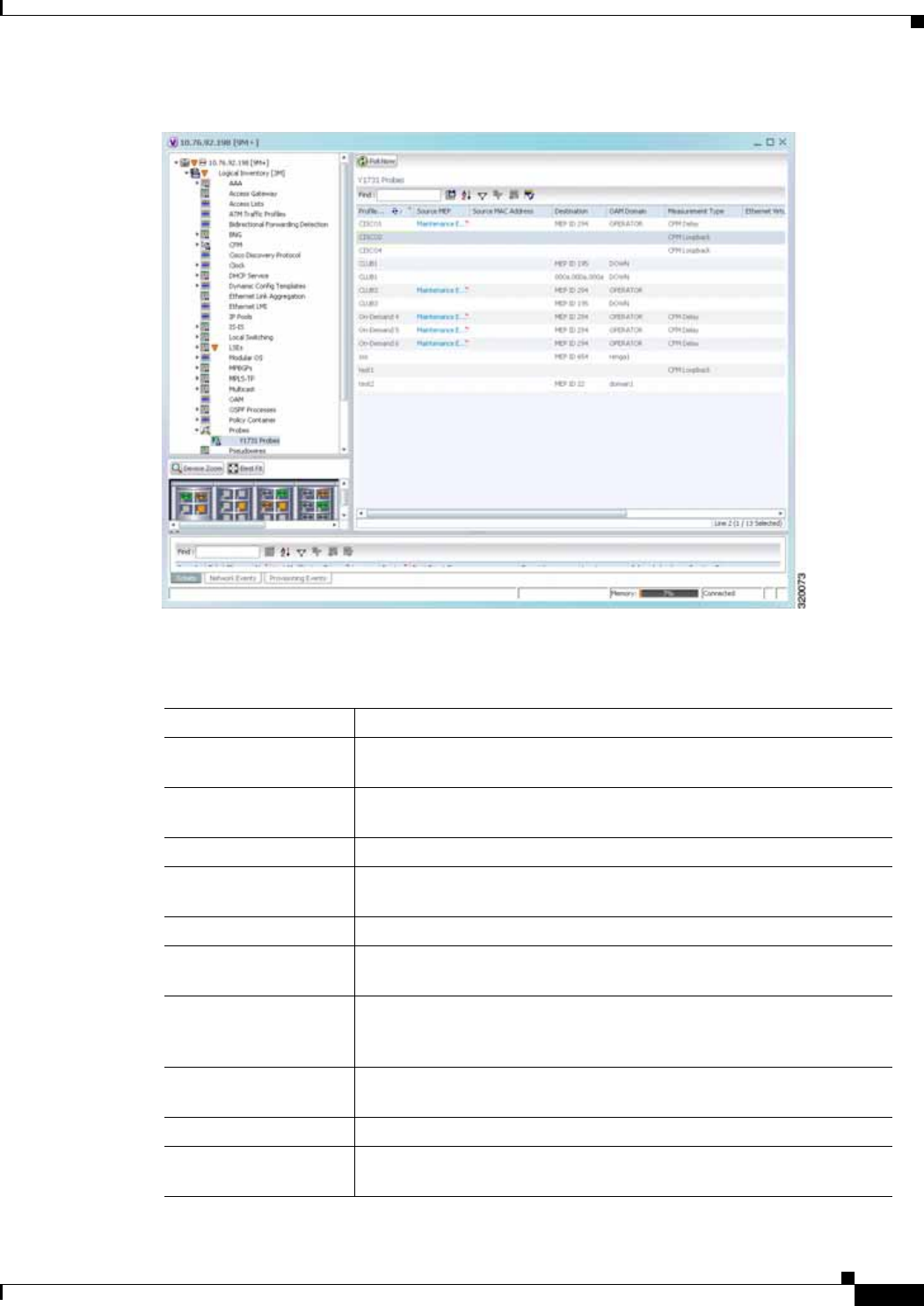
16-3
Cisco Prime Network 4.0 User Guide
OL-29343-01
Chapter 16 Monitoring Y.1731 IPSLA Configuration Working with Y.1731 IPSLA Configurations
Figure 16-1 Y.1731 Probes Content Pane
Table 16-2 describes the fields that are displayed in the content pane.
Table 16-2 Y.1731 Content Pane
Field Name Description
Profile Name The name of the profile created for performance monitoring of the SLA
configuration.
Source MEP The maintenance endpoint (MEP) interface ID where the probe is
getting initiated.
Source MAC Address The source interface MAC address where the probe is getting initiated.
Destination The interface ID or MAC address, which will help the probe to reach its
destination.
OAM Domain The name of the OAM domain.
Measurement Type The type of performance operation, which could be
cfm-delay-measurement or cfm-loopback.
Ethernet Virtual
Connection The name or identifier of the ethernet virtual connection, which
connects two User-Network Interfaces (UNI). This is applicable only for
the Cisco CPT devices.
Packet Size The size of the service packet. This includes padding size when
required.
Packets Per Burst The number of packets transmitted per burst.
Burst Period The time taken to send the packets from the source to their destination.
This period is usually specified in terms of seconds or milliseconds.

16-4
Cisco Prime Network 4.0 User Guide OL-29343-01
Chapter 16 Monitoring Y.1731 IPSLA Configuration
Working with Y.1731 IPSLA Configurations
Step 3 Right-click on a probe and choose Properties to view its properties. Additionally, the following
information is displayed in the Probe Properties window for a Cisco CPT device.
Table 16-3 describes the additional fields that are displayed for a Cisco CPT device in the Probe
Properties window.
Configuring Y.1731 Probes
You can configure Y.1731 probes using a certain set of commands. The following commands can be
launched from the inventory by right-clicking the appropriate node and selecting Commands. Before
executing any commands, you can preview them and view the results. If desired, you can also schedule
the commands. To find out if a device supports these commands, see the Cisco Prime Network 4.0
Supported Cisco VNEs.
Additional commands may be available for your devices. New commands are often provided in Prime
Network Device Packages, which can be downloaded from the Prime Network software download site.
For more information on how to download and install DPs and enable new commands, see the
information on “Adding Additional Device (VNE) support” in the Cisco Prime Network 4.0
Administrator Guide.
Table 16-3 Probe Properties Window
Field Name Description
Measurements
Statistics Type The statistics type, which is Round Trip Delay or Round Trip Jitter.
Aggregate Bin Count The aggregate count of bins to store the counter values of the result of
each performance parameter.
Note The counter value refers to the counter of number of results that
fall within a particular range specified for each performance
attribute.
Aggregate Bin
Boundaries The bin boundary for the bins. For Cisco CPT devices, bin boundary is
specified as comma separated intervals; whereas for ASR9K devices, it
is an integer. Bin boundaries are specified in terms of milliseconds.
Bucket Size The number of buckets required to store the performance attribute
results gathered during a specified period. By default, a separate bucket
is created for each probe, which will contain the results relating to
measurements made by the probe.

16-5
Cisco Prime Network 4.0 User Guide
OL-29343-01
Chapter 16 Monitoring Y.1731 IPSLA Configuration Working with Y.1731 IPSLA Configurations
Command Navigation Description
Configure Probe
EndPoint
Association
Right-click Y1731 Probes
node > Commands > Confi
guration
Use this command to configure endpoint
association for a probe.
Configure Profile Use this command to configure a new profile for the
probe.
Create On
Demand Probe
Configuration
Use this command to create an on demand probe
configuration.
Deassociate
Profile Use this command to deassociate a profile from a
probe.
Delete Profile Right-click Y1731 Probes
node > Commands > Confi
guration
Use this command to delete a profile.
Show SLA
Operations detail Right-click Y1731 Probes
node > Commands > Diag
nostics
When service providers sell connectivity services to
a subscriber, a Service Level Agreement (SLA) is
reached between the buyer and seller of the service.
The SLA defines the attributes offered by a provider
and serves as a legal obligation on the service
provider. As the level of performance required by
subscribers increases, service providers need to
monitor the performance parameters being offered.
Use this command to view the SLA operation
details.
Show SLA
Profiles Use this command to view a list of the SLA profiles.
Configure IP SLA
parameters Right-click Y1731 Probes
node > Commands > Confi
guration
Use this command to configure an IP SLA
parameter for the probe.
Delete IP SLA
parameters Use this command to delete the IP SLA parameters
for a probe.
Show IP SLA Right-click Y1731 Probes
node > Commands > Diag
nostics
Use this command to view the IP SLA schedule
details.

16-6
Cisco Prime Network 4.0 User Guide OL-29343-01
Chapter 16 Monitoring Y.1731 IPSLA Configuration
Working with Y.1731 IPSLA Configurations

CHAPTER
17-1
Cisco Prime Network 4.0 User Guide
OL-29343-01
17
IPv6 and IPv6 VPN over MPLS
Cisco Prime Network (Prime Network) supports IPv6 for:
• Gateways, clients, and units using IPv6.
• Communications between VNEs and devices in IPv6 environments, whether the device management
IP address is IPv4 or IPv6.
• Polling and notification using the following protocols over IPv6:
–
SNMP v1, SNMPv2c, and SNMPv3
–
Telnet
–
SSHv2
–
ICMP
–
XML (for Cisco IOS XR devices)
–
HTTP (for Cisco UCS and VMware vCenter devices)
• All reports with devices that use IPv6 addresses.
• Fault management, including event processing and service alarm generation.
Prime Network supports correlation and path tracing for:
• 6PE and native IPv6 networks.
• IPv6 BGP address families.
• IPv6 GRE tunnels.
IPv6 VPN over MPLS, also known as 6VPE, uses the existing MPLS IPv4 core infrastructure for IPv6
transport to enable IPv6 sites to communicate over an MPLS IPv4 core network using MPLS label switch
paths (LSPs). 6VPE relies on MP-BGP extensions in the IPv4 network configuration on the PE router to
exchange IPv6 reachability information. Edge routers are configured to be dual-stacks running both IPv4
and IPv6, and use the IPv4-mapped IPv6 address for IPv6 prefix reachability exchange.
In 6VPE environments, Prime Network supports:
• Modeling of OSPFv3 routes between PE and CE devices.
• IPv6 addresses for BGP neighbors for MP-BGP.
• Correlation and path tracing.
This chapter contains the following topics:
• User Roles Required to Work with IPv6 and 6VPE, page 17-2
• Viewing IPv6 Information, page 17-2

17-2
Cisco Prime Network 4.0 User Guide OL-29343-01
Chapter 17 IPv6 and IPv6 VPN over MPLS
User Roles Required to Work with IPv6 and 6VPE
User Roles Required to Work with IPv6 and 6VPE
This topic identifies the roles that are required to work with IPv6 and 6VPE in Prime Network Vision.
Prime Network determines whether you are authorized to perform a task as follows:
• For GUI-based tasks (tasks that do not affect elements), authorization is based on the default
permission that is assigned to your user account.
• For element-based tasks (tasks that do affect elements), authorization is based on the default
permission that is assigned to your account. That is, whether the element is in one of your assigned
scopes and whether you meet the minimum security level for that scope.
For more information on user authorization, see the Cisco Prime Network 4.0 Administrator Guide.
The following tables identify the tasks that you can perform:
• Table 17-1 identifies the tasks that you can perform if a selected element is not in one of your
assigned scopes.
• Table 17-2 identifies the tasks that you can perform if a selected element is in one of your assigned
scopes.
By default, users with the Administrator role have access to all managed elements. To change the
Administrator user scope, see the topic on device scopes in the Cisco Prime Network 4.0 Administrator
Guide.
Viewing IPv6 Information
Prime Network Vision displays IPv6 addresses when they are configured on PE and CE routers in the IP
interface table. IPv6 addresses are:
• Displayed in the Prime Network Vision map pane for IPv6 links.
• Displayed in logical and physical inventory for routing and interface information, including IP, PPP,
and High-Level Data Link Control (HDLC).
• Used in Cisco PathTracer to trace paths and present path trace results.
Table 17-1 Default Permission/Security Level Required for Viewing IPv6 Properties - Element Not
in User’s Scope
Task Viewer Operator OperatorPlus Configurator Administrator
View IPv6 properties — — — — X
Table 17-2 Default Permission/Security Level Required for Viewing IPv6 Properties - Element in
User’s Scope
Task Viewer Operator OperatorPlus Configurator Administrator
View IPv6 properties X X X X X

17-3
Cisco Prime Network 4.0 User Guide
OL-29343-01
Chapter 17 IPv6 and IPv6 VPN over MPLS Viewing IPv6 Information
Table 17-3 describes where IPv6 information appears in logical and physical inventory.
Table 17-3 IPv6 Information in Inventory
Inventory Location Description
Logical Inventory
6rd Tunnels The Tunnel Edges table displays IPv6 addresses and the IPv6
prefixes that are used to translate IPv4 addresses to IPv6 addresses.
For more information, see Viewing 6rd Tunnel Properties,
page 18-46.
Access Lists • The Type field displays IPv6 for IPv6 access lists.
• If an IPv6 access list is configured, the Access List Properties
window displays IPv6 addresses in the Source, Destination,
Source Wildcard, and Destination Wildcard fields.
Carrier Grade NAT Carrier Grade NAT service types include 6rd and XLAT.
For more information, see Viewing Carrier Grade NAT Properties in
Logical Inventory, page 13-2.
GRE Tunnels The IP Address field supports IPv6 addresses.
For more information, see Viewing MPLS Pseudowire over GRE
Properties, page 20-31.
IS-IS IS-IS properties support:
• IPv6 address families in the Metrics tab.
• IPv6 addresses in the Neighbors tab and the IS-IS Neighbor
Properties window.
For more information, see Viewing IS-IS Properties, page 12-114.
MPBGPs • IP address family identifiers indicate the BGP peer address
family: IPv4, IPv6, Layer 2 VPN, VPNv4, or VPNv6.
• MP-BGP BGP neighbor entries display IPv6 addresses.
For information, see Viewing MP-BGP Information, page 18-45.
OSPFv3 IPv6 addresses are displayed for OSPF neighbor interface
addresses, OSPF interface internet addresses, OSPF neighbor
properties window, and OSPF interface properties window.
For more information, see Viewing OSPF Properties, page 12-117.
Routing Entities • IPv6 addresses appear in the IP Interfaces tab, the IPv6 Routing
tab, and the interface properties window.
• IPv6 addresses are displayed in the NDP Table tab and the ARP
Entry Properties window.
• VRRP groups using IPv6 display IPv6 addresses in the IP
Interfaces Properties window in the VRRP group tab.
For more information, see Viewing Routing Entities, page 18-31.
VRFs IPv6 addresses appear in the IPv6 tab, Sites tab, VRF Properties
window, and IP Interface Properties window.
For more information, see Viewing VRF Properties, page 18-27.

17-4
Cisco Prime Network 4.0 User Guide OL-29343-01
Chapter 17 IPv6 and IPv6 VPN over MPLS
Viewing IPv6 Information
The IP addresses that appear depend on whether the interface has only IPv4 addresses, only IPv6
addresses, or both IPv4 and IPv6 addresses, as shown in Table 17-4.
Note the following when working with IPv6 addresses:
• MPLS label switching entries and Label Switching Entities (LSEs) do not display IPv6 addresses.
However, the Neighbor Discovery Protocol (NDP) table does display IPv6 addresses.
• Prime Network supports all the textual presentations of address prefixes. However, Prime Network
Vision displays both the IP address and the subnet prefix, for example:
12AB::CD30:123:4567:89AB:CDEF, 12AB:0:0:CD30::/60
Note Interfaces or subinterfaces that do not have IP addresses are not discovered and therefore are not shown
in Prime Network Vision.
Figure 17-1 shows a port inventory view of a port with IPv4 and IPv6 addresses. In this example, one
IPv4 address and multiple IPv6 addresses are provisioned on the interface.
• The primary IPv4 address appears in the interface table and properties window. If secondary IPv4
addresses were provisioned on the interface, they would appear in the properties window.
• IPv6 addresses provisioned on the interface appear in the properties window and Sub Interfaces tab.
Physical Inventory
Port IPv6 addresses appear in the Subinterfaces tab and interface
properties popup window.
Table 17-3 IPv6 Information in Inventory (continued)
Inventory Location Description
Table 17-4 IP Addresses Displayed in the Interface Table and Properties Window
Addresses Interface Table Properties Window
IPv4 only Primary IPv4 address The primary IPv4 address and any secondary IPv4
addresses.
IPv6 only Lowest IPv6 address All IPv6 addresses.
IPv6 and IPv4 Primary IPv4 address All IPv4 and IPv6 addresses.
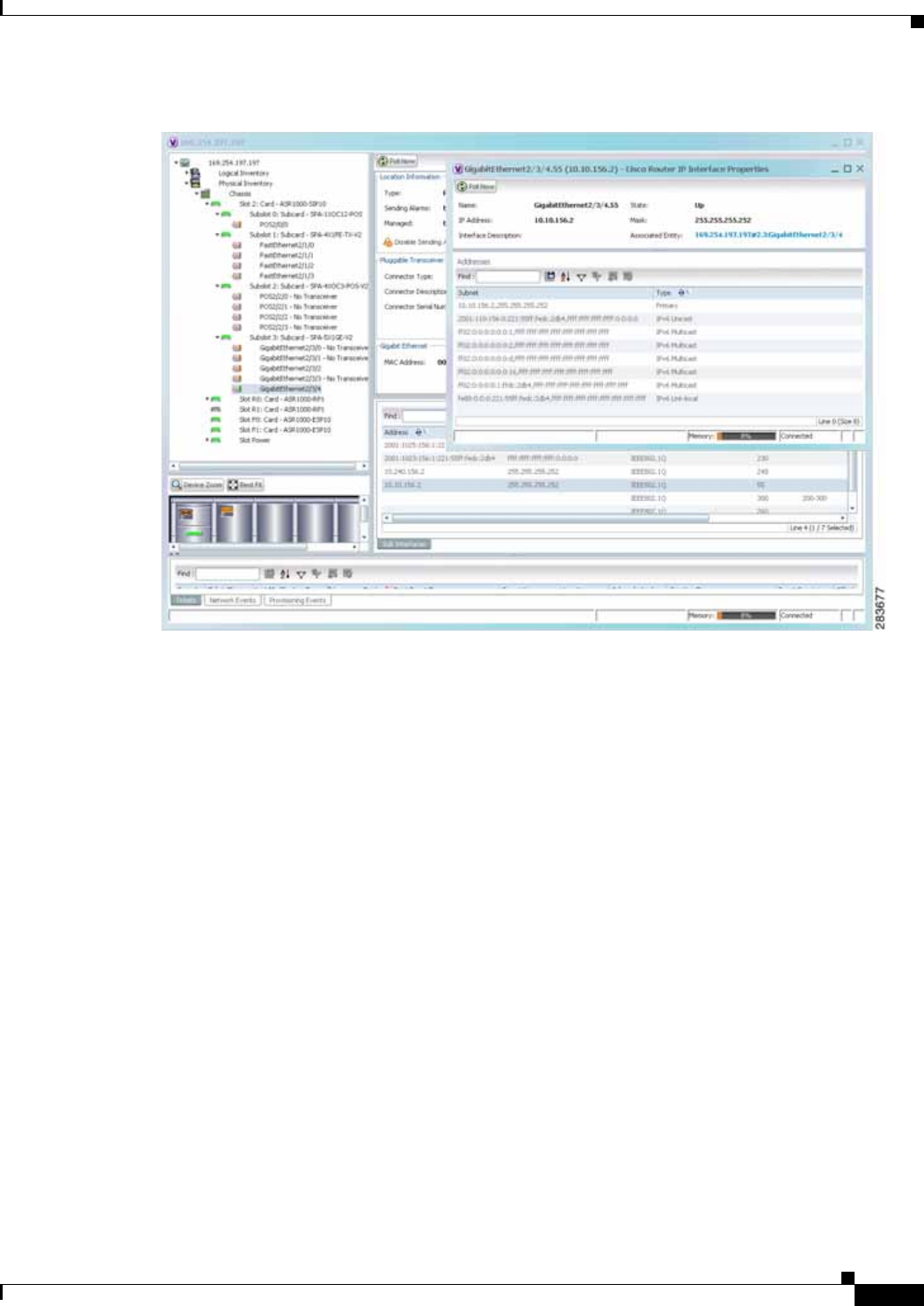
17-5
Cisco Prime Network 4.0 User Guide
OL-29343-01
Chapter 17 IPv6 and IPv6 VPN over MPLS Viewing IPv6 Information
Figure 17-1 Port with IPv4 and IPv6 Addresses
Figure 17-2 shows a port with only IPv6 addresses provisioned. In this example, the lowest IPv6 address
is shown in the subinterface table, and all IPv6 addresses are shown in the interface properties window.
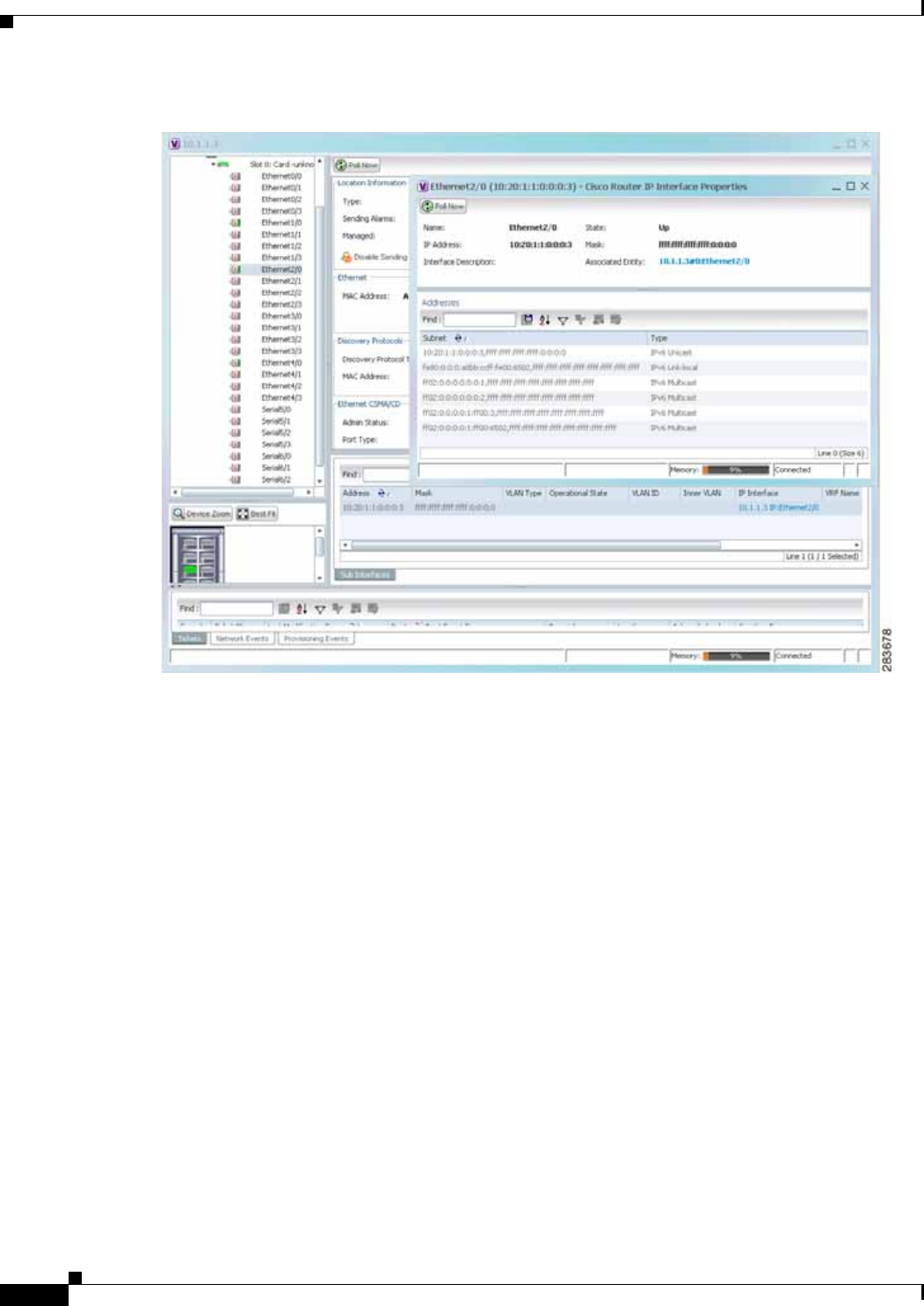
17-6
Cisco Prime Network 4.0 User Guide OL-29343-01
Chapter 17 IPv6 and IPv6 VPN over MPLS
Viewing IPv6 Information
Figure 17-2 Port with IPv6 Addresses

CHAPTER
18-1
Cisco Prime Network 4.0 User Guide
OL-29343-01
18
Monitoring MPLS Services
The following topics describe how to view and manage aspects of Multiprotocol Label Switching
(MPLS) services using Cisco Prime Network Vision (Prime Network Vision), including the MPLS
service view, business configuration, and maps. The topics also describe the device inventory specific to
MPLS VPNs, including routing entities, label switched entities (LSEs), BGP neighbors, Multiprotocol
BGP (MP-BGP), VRF instances, pseudowires, and TE tunnels. Topics include:
• User Roles Required to Work with MPLS Networks, page 18-1
• Working with MPLS-TP Tunnels, page 18-4
• Viewing VPNs, page 18-18
• Managing VPNs, page 18-21
• Working with VPN Overlays, page 18-24
• Monitoring MPLS Services, page 18-26
• Configuring VRF, page 18-53
• Configuring IP Interface, page 18-54
• Configuring MPLS-TP, page 18-54
• Configuring MPLS-TE, page 18-57
• Configuring MPLS, page 18-57
• Configuring RSVP, page 18-58
• Configuring BGP, page 18-59
• Configuring VRRP, page 18-60
• Configuring Bundle Ethernet, page 18-61
User Roles Required to Work with MPLS Networks
This topic identifies the roles that are required to work with MPLS networks. Prime Network determines
whether you are authorized to perform a task as follows:
• For GUI-based tasks (tasks that do not affect elements), authorization is based on the default
permission that is assigned to your user account.
• For element-based tasks (tasks that do affect elements), authorization is based on the default
permission that is assigned to your account. That is, whether the element is in one of your assigned
scopes and whether you meet the minimum security level for that scope.

18-2
Cisco Prime Network 4.0 User Guide OL-29343-01
Chapter 18 Monitoring MPLS Services
User Roles Required to Work with MPLS Networks
For more information on user authorization, see the Cisco Prime Network 4.0 Administrator Guide.
The following tables identify the tasks that you can perform:
• Table 18-1 identifies the tasks that you can perform if a selected element is not in one of your
assigned scopes.
• Table 18-2 identifies the tasks that you can perform if a selected element is in one of your assigned
scopes.
By default, users with the Administrator role have access to all managed elements. To change the
Administrator user scope, see the topic on device scopes in the Cisco Prime Network 4.0 Administrator
Guide.
Table 18-1 Default Permission/Security Level Required for Working with MPLS Networks -
Element Not in User’s Scope
Task Viewer Operator OperatorPlus Configurator Administrator
Working with Elements
Add tunnels to VPNs — X X X X
Add VPNs to a map — — X X X
Create VPNs — — X X X
Move virtual routers between VPNs — X X X X
Remove tunnels from VPNs X X X X X
Remove VPNs from a map — — X X X
Viewing Element Properties
View 6RD properties — — — — X
View BFD properties — — — — X
View cross-VRF routing entries — — — — X
View LSE properties — — — — X
View MP-BGP information — — — — X
View MPLS TE tunnel information — — — — X
View MPLS-TP information — — — — X
View port configurations — — — — X
View pseudowire end-to-end
emulation tunnels —— — — X
View rate limit information — — — — X
View the ARP table — — — — X
View the NDP table — — — — X
View VPN properties X X X X X
View VPNs X X X X X
View VRF egress and ingress
adjacents —— — — X
View VRF properties — — — — X
Working with Overlays
Add VPN overlays X X X X X

18-3
Cisco Prime Network 4.0 User Guide
OL-29343-01
Chapter 18 Monitoring MPLS Services User Roles Required to Work with MPLS Networks
Display or hide VPN overlays X X X X X
Remove VPN overlays X X X X X
Table 18-2 Default Permission/Security Level Required for Working with MPLS Networks -
Element in User’s Scope
Task Viewer Operator OperatorPlus Configurator Administrator
VPNs and VRFs
Add tunnels to VPNs — X X X X
Add VPNs to a map — — X X X
Create VPNs — — X X X
Display VRF egress and ingress
adjacents —— — — X
Move virtual routers between VPNs — X X X X
Remove tunnels from VPNs X X X X X
Remove VPNs from a map — — X X X
View VPN properties X X X X X
View VPNs X X X X X
View VRF properties — — — — X
VPN Overlays
Add VPN overlays X X X X X
Display or hide VPN overlays X X X X X
Remove VPN overlays X X X X X
Routing Entities
View the ARP table X X X X X
View the NDP table X X X X X
View rate limit information X X X X X
Other
View 6RD properties X X X X X
View BFD properties X X X X X
View cross-VRF routing entries X X X X X
View LSE properties X X X X X
View MP-BGP information X X X X X
View MPLS TE tunnel information X X X X X
View MPLS-TP information X X X X X
Table 18-1 Default Permission/Security Level Required for Working with MPLS Networks -
Element Not in User’s Scope (continued)
Task Viewer Operator OperatorPlus Configurator Administrator

18-4
Cisco Prime Network 4.0 User Guide OL-29343-01
Chapter 18 Monitoring MPLS Services
Working with MPLS-TP Tunnels
Working with MPLS-TP Tunnels
MPLS-Transport Profile (MPLS-TP) is considered to be the next generation transport for those using
SONET/SDH TDM technologies as they migrate to packet-switching technology. Although still under
definition by the IETF, MPLS-TP provides:
• Predetermined and long-lived connections.
• Emphasis on manageability and deterministic behavior.
• Fast fault detection and recovery.
• Inband OAM.
MPLS-TP features include:
• Manually provisioned MPLS-TP LSPs.
• Reserved bandwidth for static MPLS-TP LSPs.
• One-to-one path protection for MPLS-TP LSPs.
• Working/Protected LSP switchover.
• Continuity Check (CC), Proactive Continuity Verification (CV), and Remote Defect Indication
(RDI) based on BFD.
• New fault OAM functions resulting from the MPLS-TP standardization effort.
Prime Network automatically discovers network MPLS-TP tunnels from end to end, including LSPs,
tunnel endpoints, and bandwidth. Network LSPs contain LSP endpoints and midpoints and are identified
as working or protected.
Prime Network links the MPLS-TP tunnel components appropriately, provides a visual representation in
Prime Network Vision maps, and displays the properties in logical inventory.
Prime Network employs warm start technology when rebooting. That is, when rebooting, Prime Network
compares existing MPLS-TP tunnel information to topology changes that occur while Prime Network is
down and updates MPLS-TP tunnel accordingly when Prime Network returns to operation.
The following options are available for working with MPLS-TP tunnels in Prime Network Vision:
• Adding an MPLS-TP Tunnel, page 18-5
• Viewing MPLS-TP Tunnel Properties, page 18-7
• Viewing LSPs Configured on an Ethernet Link, page 18-11
• Viewing LSP Endpoint Redundancy Service Properties, page 18-14
• Applying an MPLS-TP Tunnel Overlay, page 18-16
• Viewing MPLS-TP BFD session properties—See Viewing BFD Session Properties, page 18-47.
View port configurations X X X X X
View pseudowire end-to-end
emulation tunnels XX X X X
Table 18-2 Default Permission/Security Level Required for Working with MPLS Networks -
Element in User’s Scope (continued)
Task Viewer Operator OperatorPlus Configurator Administrator

18-5
Cisco Prime Network 4.0 User Guide
OL-29343-01
Chapter 18 Monitoring MPLS Services Working with MPLS-TP Tunnels
Adding an MPLS-TP Tunnel
Prime Network Vision automatically discovers MPLS-TP tunnels, endpoints, and midpoints and enables
you to add MPLP-TP tunnels to maps.
To add an MPLS-TP tunnel to a map:
Step 1 In Prime Network Vision, display the map to which you want to add the MPLS-TP tunnel.
Step 2 Do either of the following:
• From the File menu, choose Add to Map > MPLS-TP Tunnel.
• In the main toolbar, click Add to Map, then choose Add to Map > MPLS-TP Tunnel.
The Add MPLS-TP Tunnel dialog box is displayed.
Step 3 Do either of the following:
• Choose a search category, enter a search string, then click Go to narrow search results to a range of
MPLS-TP tunnels or a specific MPLS-TP tunnel. Search categories include:
–
Description
–
Name
–
System Name
• Choose Show All to display all the MPLS-TP tunnels.
Step 4 Select the MPLS-TP tunnel that you want to add to the map.
Step 5 Click OK.
The MPLS-TP tunnel is added to the map and to the navigation pane.
In Figure 18-1:
• The devices are on the left side of the map, and the MPLS-TP tunnel is displayed in a thumbnail on
the right.
• The devices are connected to each other and to the MPLS-TP tunnel via tunnels.
• Physical links connect the devices to the Working and Protected LSPs.
• A redundancy service badge is displayed next to the Protected LSP in the navigation and map panes.
• In the thumbnail:
–
The tunnel endpoints are connected to each other via a tunnel.
–
A physical link connects the Working and Protected LSPs.
–
Business links connect the Working and Protected LSPs to each endpoint.
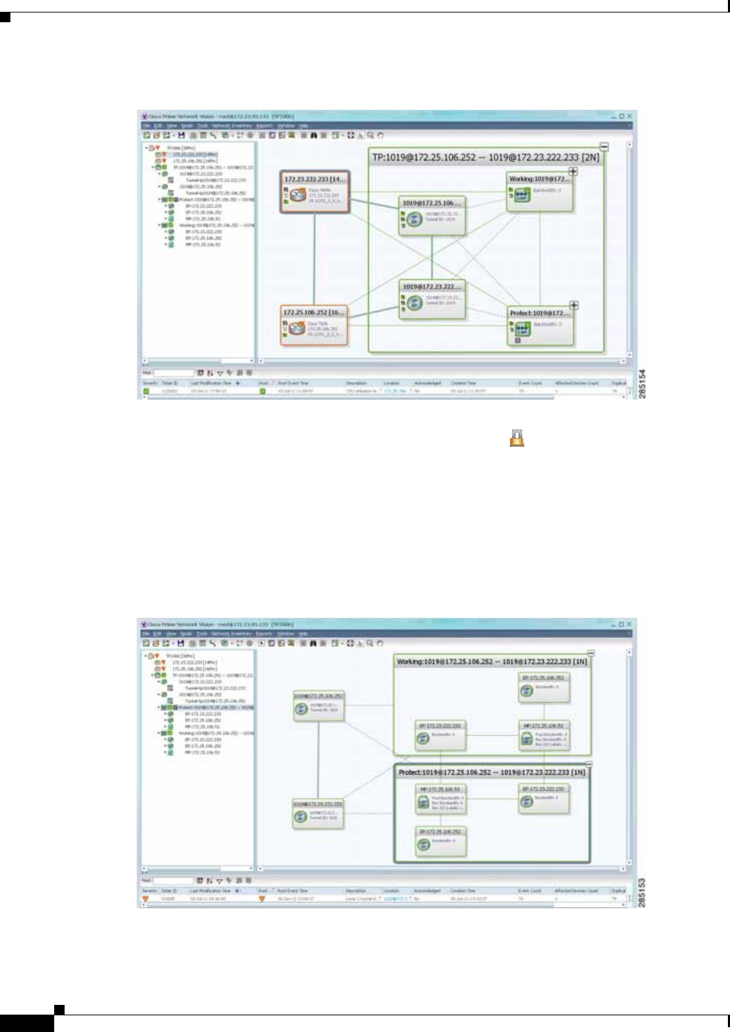
18-6
Cisco Prime Network 4.0 User Guide OL-29343-01
Chapter 18 Monitoring MPLS Services
Working with MPLS-TP Tunnels
Figure 18-1 MPLS-TP Tunnel in Prime Network Vision Map
If an LSP is in lockout state, it is displayed with the lock badge ( ).
By expanding all aggregations in the MPLS-TP tunnel (see Figure 18-2), you can see components and
links in the MPLS-TP tunnel, including:
• MPLS-TP tunnel endpoints
• LSP endpoints
• LSP midpoints
Figure 18-2 MPLS-TP Tunnel Expanded
If an LSP is configured for redundancy service, a redundancy service badge is applied to the secondary
(backup) LSP in the navigation and map panes in the navigation and map panes.
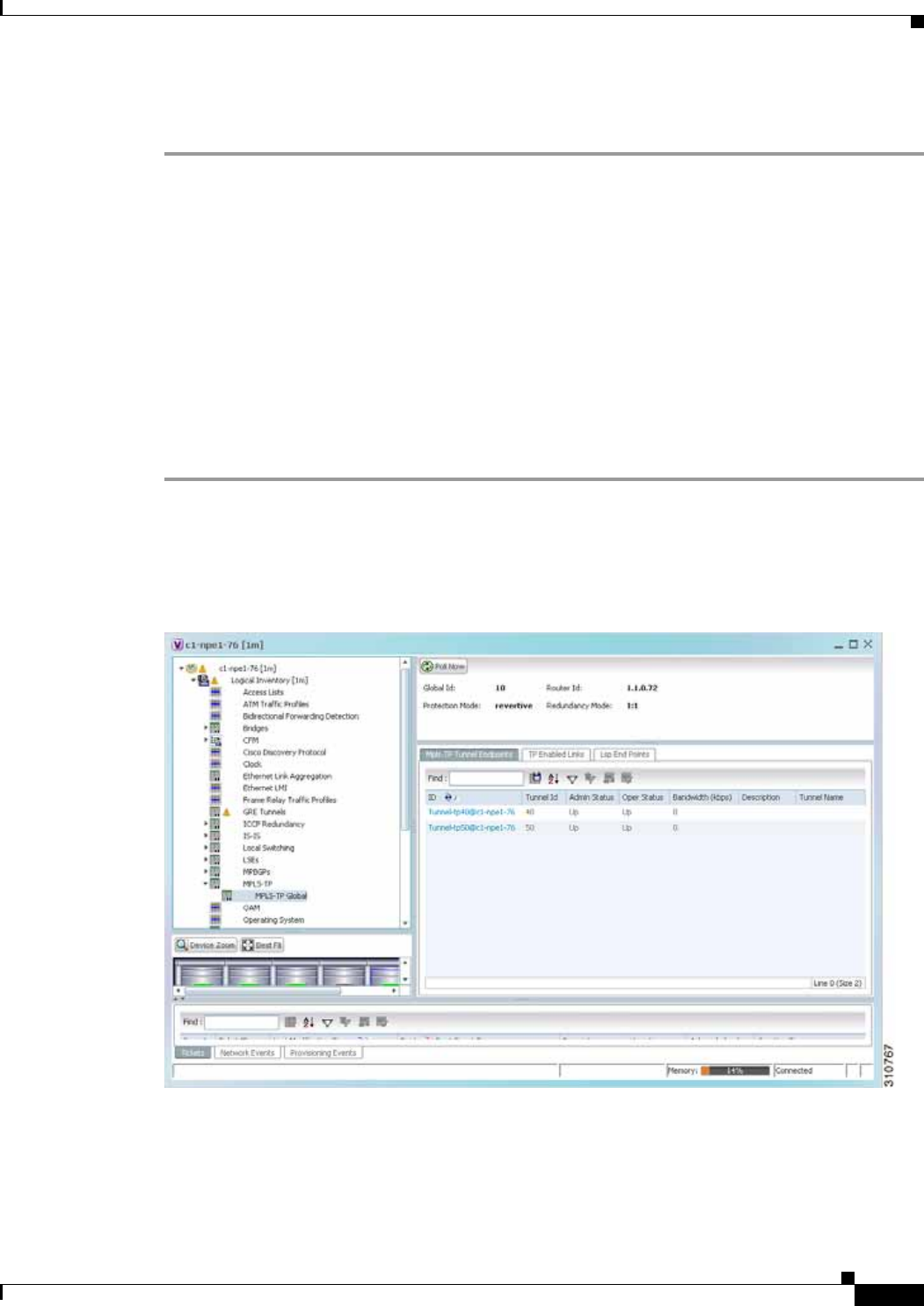
18-7
Cisco Prime Network 4.0 User Guide
OL-29343-01
Chapter 18 Monitoring MPLS Services Working with MPLS-TP Tunnels
For more information about LSP redundancy service, see Viewing LSP Endpoint Redundancy Service
Properties, page 18-14.
Viewing MPLS-TP Tunnel Properties
Prime Network Vision discovers and displays MPLS-TP attributes in the MPLS-TP branch in logical
inventory as described in this topic.
Additional information about MPLS-TP tunnel properties are available in the following branches:
• Routing Entities—See Viewing Routing Entities, page 18-31.
• LSEs—See Viewing Label Switched Entity Properties, page 18-39.
• Pseudowires— See Viewing Pseudowire End-to-End Emulation Tunnels, page 18-50.
To view MPLS-TP tunnel properties:
Step 1 Right-click the required device in Prime Network Vision and choose Inventory.
Step 2 In the logical inventory window, choose Logical Inventory > MPLS-TP > MPLS-TP Global.
The routing information is displayed as shown in Figure 18-3.
Figure 18-3 MPLS-TP Tunnel Properties in Logical Inventory
Table 18-3 describes the information that is available for MPLS-TP tunnels. The information that is
displayed depends on the configuration.

18-8
Cisco Prime Network 4.0 User Guide OL-29343-01
Chapter 18 Monitoring MPLS Services
Working with MPLS-TP Tunnels
Table 18-3 MPLS-TP Tunnel Properties in Logical Inventory
Field Description
Global ID Globally unique Attachment Interface Identifier (AII) for MPLS-TP derived
from the Autonomous System Number (ASN) of the system hosting the PEs.
Router ID MPLS-TP source node identifier for this element in the form of an IPv4
address.
Protection Mode Whether the transmitting endpoint is in revertive or nonrevertive mode:
• Revertive—If the protection mode is revertive and a failed path is
restored, the traffic automatically returns, or reverts, to the original path.
• Nonrevertive—If the protection mode is nonrevertive and a failed path
is restored, the traffic does not return to the original path. That is, the
traffic does not revert to the original path.
Redundancy Mode Level of redundancy for the MPLS-TP tunnel: 1:1, 1+1, or 1:N.
MPLS-TP Tunnel Endpoints Tab
ID Tunnel endpoint identifier as a Tunnel-tp interface on the selected network
element.
Tunnel ID Unique tunnel identifier.
Admin Status Administrative status of the tunnel: Up or Down.
Oper Status Operational status of the tunnel: Up or Down.
Bandwidth (kbps) Configured bandwidth (in Kb/s) for the tunnel.
Description Tunnel description.
TP Enabled Links Tab
Link ID Identifier assigned to the MPLS-TP interface.
Interface Hyperlink to the interface in physical inventory.
Next Hop IP address of the next hop in the path.
LSP End Points Tab
LSP ID LSP identifier, derived from both endpoint identifiers and using the format
src-node-ID::src-tunnel-number::dest-node-ID::dest-tunnel-number where:
• src-node-ID represents the identifier of the node originating the signal
exchange.
• src-tunnel-number represents source tunnel identifier.
• dest-node-ID represents the identifier of the target node.
• dest-tunnel-number represents the destination tunnel identifier.
LSP Type Indicates whether the LSP is active (Working) or backup (Protect).
In Label Incoming label identifier.
Out Label Outgoing label identifier.
Out Interface Outgoing interface hyperlinked to the relevant entry in physical inventory.
Bandwidth (kbps) Bandwidth specification in Kb/s.
Role (Oper Status) Role of the LSP endpoint (Active or Standby) with the operational status (UP
or DOWN).

18-9
Cisco Prime Network 4.0 User Guide
OL-29343-01
Chapter 18 Monitoring MPLS Services Working with MPLS-TP Tunnels
Step 3 To view additional MPLS-TP tunnel endpoint properties, double-click the required entry in the
MPLS-TP Tunnel Endpoints table.
The MPLS-TP Tunnel Properties window is displayed as shown in Figure 18-4.
LSP Mid Points Tab
LSP ID LSP identifier, derived from both endpoint identifiers and using the format
src-node-ID::src-tunnel-number::dest-node-ID::dest-tunnel-number where:
• src-node-ID represents the identifier of the node originating the signal
exchange.
• src-tunnel-number represents source tunnel identifier.
• dest-node-ID represents the identifier of the target node.
• dest-tunnel-number represents the destination tunnel identifier.
LSP Type Indicates whether the LSP is active (Working) or backup (Protect).
Forward In Label Incoming label identifier in the forward direction (source to destination).
Forward Out Label Label selected by the next hop device in the forward direction.
Reverse In Label Incoming label identifier in the reverse direction (destination to source).
Reverse Out Label Label selected by the next hop device in the reverse direction.
Forward Out Interface Outgoing interface in the forward direction, hyperlinked to its entry in
physical inventory.
Forward Bandwidth
(kbps) Bandwidth specification in Kb/s for the forward direction.
Reverse Out Link ID Link identifier assigned to the outgoing interface in the reverse direction.
Reverse Out Interface Outgoing interface in the reverse direction, hyperlinked to its entry in
physical inventory.
Reverse Bandwidth Bandwidth specification in Kb/s for the reverse direction.
Internal ID Identifier associated with the parent entity of the link. Using an internal
identifier ensures that individual LSP links do not participate in multiple
network LSPs.
Table 18-3 MPLS-TP Tunnel Properties in Logical Inventory (continued)
Field Description

18-10
Cisco Prime Network 4.0 User Guide OL-29343-01
Chapter 18 Monitoring MPLS Services
Working with MPLS-TP Tunnels
Figure 18-4 MPLS-TP Tunnel Properties Window
Table 18-4 describes the information available in the top portion of the MPLS-TP Tunnel Properties
window. For information about the tabs that are displayed, see Table 18-3.
Table 18-4 MPLS-TP Tunnel Properties Window
Field Description
Tunnel ID Unique tunnel identifier.
Peer Tunnel ID Unique identifier of peer tunnel.
Bandwidth (kbps) Configured bandwidth (in Kb/s) for the tunnel.
Admin Status Administrative status of the tunnel: Up or Down.
Oper Status Operational status of the tunnel: Up or Down.
Local Info MPLS-TP source node identifier for this element in the form of an
IPv4 address.
Peer Info MPLS-TP peer node identifier in the form of an IPv4 address.
Global ID Globally unique Attachment Interface Identifier (AII) for MPLS-TP
derived from the Autonomous System Number (ASN) of the system
hosting the PEs.
Peer Global ID Globally unique AII for the peer.
Working LSP Number Number assigned to the working LSP. By default, the working LSP
number is 0 and the protected LSP number is 1.

18-11
Cisco Prime Network 4.0 User Guide
OL-29343-01
Chapter 18 Monitoring MPLS Services Working with MPLS-TP Tunnels
Viewing LSPs Configured on an Ethernet Link
A single Ethernet link can support a number of LSPs. Prime Network Vision enables you to view all
LSPs on a single Ethernet link and to identify the source and destination labels.
To view LSPs configured on an Ethernet link:
Step 1 In the map view, right-click the required link and choose Properties.
Step 2 In the link properties window, choose the required Ethernet link.
The link properties window refreshes and displays the Labels button as shown in Figure 18-5.
Protect LSP Number Number assigned to the protected LSP. By default, the working LSP
number is 0 and the protected LSP number is 1.
BFD Template BFD template associated with this MPLS-TP tunnel.
Working LSP BFD State Configured state of the working LSP BFD template: Up or Down.
Protect LSP BFD State Configured state of the protected LSP BFD template: Up or Down.
Working LSP Fault OAM Indicates that a fault has been detected on the working LSP.
Protect LSP Fault OAM Indicates that a fault has been detected on the protected LSP.
Tunnel Name Tunnel name.
Adjacent Hyperlink to the adjacent endpoint in logical inventory.
Table 18-4 MPLS-TP Tunnel Properties Window (continued)
Field Description
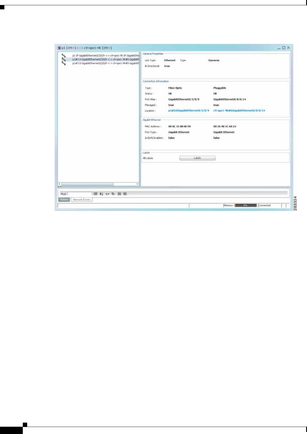
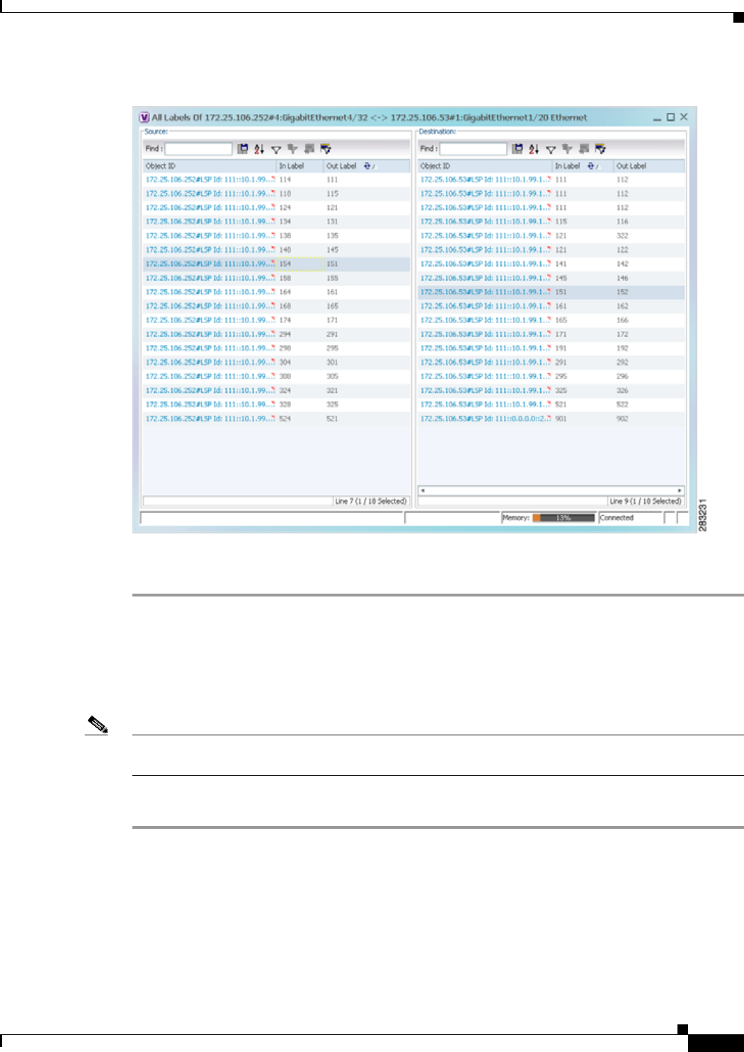
18-13
Cisco Prime Network 4.0 User Guide
OL-29343-01
Chapter 18 Monitoring MPLS Services Working with MPLS-TP Tunnels
Figure 18-6 All Labels Table
Step 4 To identify a specific path, click an outgoing label in the Source table. The corresponding in label is
selected in the Destination table.
Viewing MPLS-TE and P2MP-MPLS-TE links in a map
Using the link filter available in Prime Network, you can view only the MPLS-TE and P2MP-MPLS-TE
links in a map.
Note The MPLS Point-to-Multipoint Traffic Engineering (P2MP TE) feature enables you to forward
Multiprotocol Label Switching (MPLS) traffic from one source to multiple destinations.
To view the MPLS-TE and P2MP-MPLS-TE links in a map:
Step 1 Open the required map.
Step 2 Click the Link filter icon in the navigation menu.
Step 3 In the Link Filter window, select the MPLS-TE and P2MP MPLS-TE check boxes.
Step 4 Click OK. The map refreshes and displays only the MPLS-TE and P2MP MPLS-TE links.
Step 5 Right-click on the link and choose the Properties option.
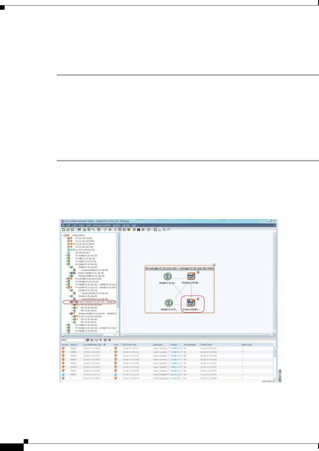
18-14
Cisco Prime Network 4.0 User Guide OL-29343-01
Chapter 18 Monitoring MPLS Services
Working with MPLS-TP Tunnels
Step 6 In the Link Properties window, the type of link is displayed in the Link Type field, which can be either
MPLS-TE and P2MP MPLS-TE based on the link that you have selected. Additional details about the
link such as the MPLS TE tunnel, operational status of the tunnel, TE tunnel type are displayed in the
Label Switching section. For more information about the Link Properties window, see Viewing LSPs
Configured on an Ethernet Link, page 18-11.
Viewing LSP Endpoint Redundancy Service Properties
If an LSP endpoint in an MPLS-TP tunnel is configured for redundancy service, a redundancy service
badge is applied to the secondary (backup) LSP endpoint in the navigation and map panes in Prime
Network Vision. Additional redundancy service details are provided in the LSP endpoint properties
window and the inventory window for the element on which the MPLS-TP tunnel is configured.
To view LSP endpoint redundancy service properties:
Step 1 To determine if an LSP endpoint on an MPLS-TP tunnel is configured for redundancy service, expand
the required MPLS-TP tunnel in the navigation or map pane.
If the LSP endpoint is configured for redundancy service, the redundancy service badge is displayed in
the navigation and map panes as shown in Figure 18-7.
Figure 18-7 LSP Endpoint with Redundancy Service Badge
Step 2 To view properties for the LSP endpoint, navigate to and right-click the required endpoint in the map or
navigation pane, and choose Properties.
The LSP endpoint properties window is displayed as shown in Figure 18-8.
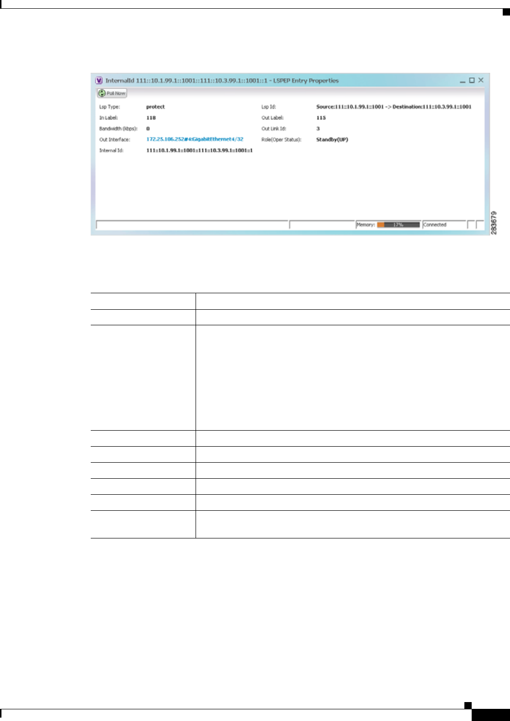
18-15
Cisco Prime Network 4.0 User Guide
OL-29343-01
Chapter 18 Monitoring MPLS Services Working with MPLS-TP Tunnels
Figure 18-8 LSP Endpoint Properties Window
Table 18-5 describes the information displayed in the LSP Endpoint Properties window.
Step 3 To view LSP endpoint redundancy status in inventory, double-click the element on which the MPLS-TP
tunnel is configured.
Step 4 Choose Logical Inventory > MPLS-TP > MPLS-TP Global > LSP End Points.
Step 5 The LSP End Points tab contains the following information related to LSP redundancy service (see
Figure 18-9):
• Whether the LSP endpoint is Working or Protected.
• The LSP endpoint role, either Active or Standby.
• The operational status of the LSP endpoint, either Up or Down.
Table 18-5 LSP Endpoint Properties Window
Field Description
LSP Type Indicates whether the LSP is active (Working) or backup (Protected).
LSP ID LSP identifier, derived from both endpoint identifiers and using the format
src-node-ID::src-tunnel-number::dest-node-ID::dest-tunnel-number where:
• src-node-ID represents the identifier of the node originating the signal
exchange.
• src-tunnel-number represents source tunnel identifier.
• dest-node-ID represents the identifier of the target node.
• dest-tunnel-number represents the destination tunnel identifier.
In Label Incoming label identifier.
Out Label Outgoing label identifier.
Bandwidth (kbps) Bandwidth specification in Kb/s.
Out Link ID Link identifier assigned to the outgoing interface.
Out Interface Outgoing interface hyperlinked to the relevant entry in physical inventory.
Role (Oper Status) Role of the LSP endpoint (Active or Standby) with the operational status (UP
or DOWN)
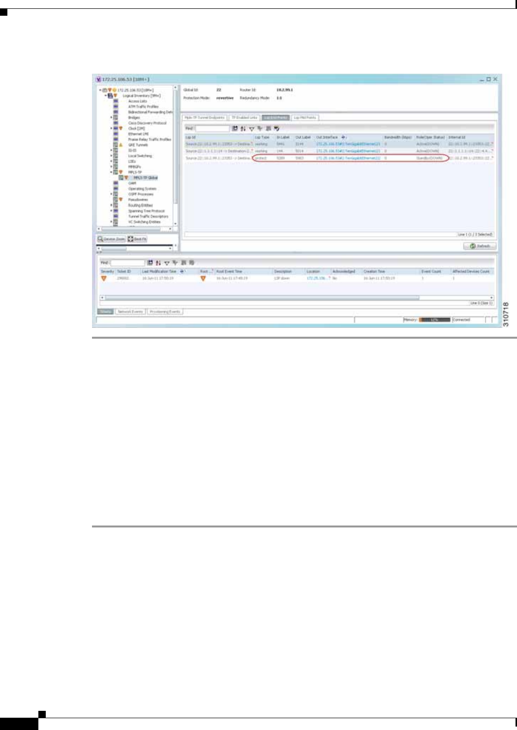
18-16
Cisco Prime Network 4.0 User Guide OL-29343-01
Chapter 18 Monitoring MPLS Services
Working with MPLS-TP Tunnels
Figure 18-9 LSP End Points Tab in Logical Inventory
Applying an MPLS-TP Tunnel Overlay
You can select and display an overlay of a specific MPLS-TP tunnel on top of the devices displayed in
a map view. The overlay is a snapshot of the network that visualizes the flows between the sites and
tunnel peers. When an MPLS-TP tunnel is selected in the map, the following elements are highlighted
in the map:
• Elements on which TP endpoints and LSPs are configured.
• Links that carry TP traffic.
All elements and links that are not part of the MPLS-TP tunnel are dimmed.
To apply an MPLS-TP tunnel overlay:
Step 1 In Prime Network Vision, display the network map on which you want to apply an overlay.
Step 2 From the main toolbar, click Choose Overlay Type and choose MPLS-TP tunnel.
The Select MPLS-TP tunnel Overlay dialog box is displayed.
Step 3 Do one of the following:
• Choose a search category, enter a search string, then click Go to narrow the search results to a range
of MPLS-TP tunnels or a specific MPLS-TP tunnel. Search categories include:
–
Description
–
Name
–
System Name
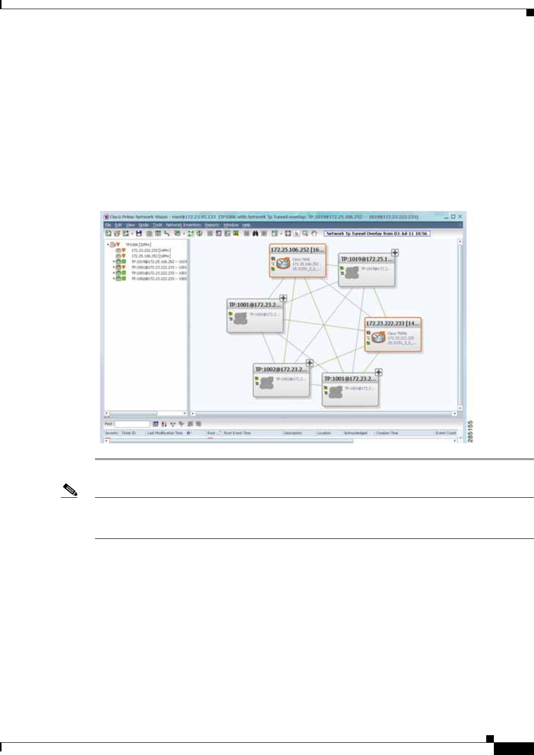
18-17
Cisco Prime Network 4.0 User Guide
OL-29343-01
Chapter 18 Monitoring MPLS Services Working with MPLS-TP Tunnels
The search condition is “contains.” Search strings are case-insensitive. For example, if you choose
the Name category and enter “net,” Prime Network Vision displays MPLS-TP tunnels that have
“net” in their names whether net appears at the beginning of the name, the middle, or at the end: for
example, Ethernet.
• Choose Show All to display all MPLS-TP tunnels.
Step 4 Select the MPLS-TP tunnel overlay you want to apply to the map.
The elements and links used by the selected MPLS-TP tunnel are highlighted in the network map, and
the MPLS-TP tunnel name is displayed in the window title bar as shown in Figure 18-10.
Figure 18-10 MPLS-TP Tunnel Overlay
Note An overlay is a snapshot taken at a specific point in time and does not reflect changes that occur in the
service. As a result, the information in an overlay can become stale. To update the overlay, click Refresh
Overlay in the main toolbar.
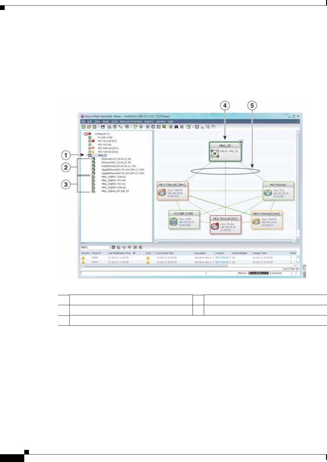
18-18
Cisco Prime Network 4.0 User Guide OL-29343-01
Chapter 18 Monitoring MPLS Services
Viewing VPNs
Viewing VPNs
Figure 18-11 shows a VPN displayed in the Prime Network Vision map view. In this example, the VPN
is selected in the navigation pane, so the VPN details, such as virtual routers and IP interfaces, are not
shown in the map view.
Figure 18-11 VPN in Prime Network Vision Map View
1VPN in the navigation tree 4VPN in the map view
2Sites 5VPN links
3Virtual routers

18-19
Cisco Prime Network 4.0 User Guide
OL-29343-01
Chapter 18 Monitoring MPLS Services Viewing VPNs
Figure 18-12 shows a VPN with details, including virtual routers and sites, in the Prime Network Vision
map view.
Figure 18-12 VPN in Prime Network Vision Map View with VRFs and Sites
The Prime Network Vision navigation pane displays the VPN business elements in a tree-and-branch
representation. Each business element is represented by an icon in a color that reflects the highest alarm
severity. The icon might also have a management state badge or alarm. For more information about icon
severity colors and badges, see Prime Network Vision Status Indicators, page 2-17.
1Virtual routers
2Sites

18-20
Cisco Prime Network 4.0 User Guide OL-29343-01
Chapter 18 Monitoring MPLS Services
Viewing VPNs
Table 18-6 shows the VPN icons in the Prime Network Vision map view.
The highest level of the navigation pane displays the root or map name. The branches display the VPN
and aggregated business elements as well as their names. The Layer 3 VPN sub-branch displays the
virtual routers and sites contained in the VPN along with the names of the business elements. In addition,
CE devices can be displayed in the Layer 2 and Layer 3 VPN sub-branches. If you select an aggregated
business element in the navigation pane, the map view displays the business elements contained within
the aggregated business element.
The Prime Network Vision map view displays the VPN business elements and aggregated business
elements loaded in the map view, along with the names of the business elements. In addition, the map
view displays the VPN topology (between the virtual routers in the VPNs) and the topology and
associations between other business elements. After you select the root in the navigation pane, the map
view displays all the VPNs.
Prime Network Vision presents tickets related to the map in the ticket area, which allows you to view
and manage the VPN tickets.
Viewing Additional VPN Properties
Prime Network Vision allows you to select any element in the navigation pane or map view and view
additional underlying properties. To view additional properties for an object, either double-click it or
right-click it and choose Properties. Table 18-7 shows the additional properties available for VPN
entities.
Table 18-6 VPN Icons in Prime Network Vision Map View
Icon Description
Root (map name) or aggregation
VPN
Virtual router
Site
Table 18-7 Displaying Additional VPN Properties
Object Option For Additional Information
VPN • Double-click a VPN to view the
participating VRFs, sites, and network
elements in the navigation pane and map
view.
• Right-click a VPN and choose Properties to
view the VPN Properties window.
Viewing VPN Properties, page 18-26
VRF Double-click a VRF to view the VRF properties
window. Viewing VRF Properties, page 18-27

18-21
Cisco Prime Network 4.0 User Guide
OL-29343-01
Chapter 18 Monitoring MPLS Services Managing VPNs
Managing VPNs
The following topics describe:
• Creating a VPN, page 18-21
• Adding a VPN to a Map, page 18-22
• Removing a VPN from a Map, page 18-23
• Moving a Virtual Router Between VPNs, page 18-23
Creating a VPN
You can change business configurations by manually creating VPNs. The VPNs that are manually
created do not contain virtual routers and sites.
To create a VPN:
Step 1 In the Prime Network Vision navigation pane, select the map root.
Step 2 From the File menu, choose Add to Map > VPN > New.
Step 3 In the Create VPN dialog box, enter the following:
• Name—A unique name for the new VPN.
Note VPN business element names are case sensitive.
• Icon—To use a custom icon for the VPN, click the button next to the Icon field and navigate to the
icon file.
Note If a path is not specified to an icon, the default VPN icon is used (for more information about
icons, see Table 18-6 on page 18-20).
• Description—(Optional) An additional VPN description.
Step 4 Click OK.
The new VPN is added to the VPN list in the Add VPN dialog box.
Site Double-click a site to view the IP Interface
Properties window Viewing Site Properties, page 18-27
Link Double-click a link to view the link properties
window. The properties that are depend on the
link type.
Chapter 6, “Working with Links”
Table 18-7 Displaying Additional VPN Properties (continued)
Object Option For Additional Information

18-22
Cisco Prime Network 4.0 User Guide OL-29343-01
Chapter 18 Monitoring MPLS Services
Managing VPNs
For more information about loading the newly created VPN in the service view map, see Adding a VPN
to a Map, page 18-22.
Adding a VPN to a Map
You can add a VPN to a map view if the VPN was previously created by a user or discovered by Prime
Network Vision and are not currently displayed in the map.
Note Adding a VPN affects other users if they are working with the same map.
To add an existing VPN to a map:
Step 1 In Prime Network Vision, display the map to which you want to add the VPN.
Step 2 Do either of the following:
• From the File menu, choose Add to Map > VPN > Existing.
• In the main toolbar, click Add to Map, then choose Add to Map > VPN > Existing.
The Add VPN dialog box is displayed.
Step 3 Do either of the following:
• Choose a search category, enter a search string, then click Go to narrow search results to a range of
VPNs or a specific VPN. Search categories include:
–
Description
–
Name
The search condition is “contains.” Search strings are case-insensitive. For example, if you choose
the Name category and enter “net,” Prime Network Vision displays VPNs that have “net” in their
names whether at the beginning of the name, the middle, or the end.
• Choose Show All to display all the VPNs.
Step 4 Select the VPN that you want to add to the map.
Tip Press Shift or Ctrl to choose multiple adjoining or nonadjoining VPNs.
Step 5 Click OK.
The VPN is displayed in the navigation pane and the selected map or subnetwork in the Prime Network
Vision window content pane. In addition, any tickets are displayed in the ticket area.

18-23
Cisco Prime Network 4.0 User Guide
OL-29343-01
Chapter 18 Monitoring MPLS Services Managing VPNs
Removing a VPN from a Map
You can remove one or more VPNs from the current active map. This change does not affect other maps.
Removing a VPN from a map does not remove it from the Prime Network Vision database. The VPN
will appear in the Add VPN dialog box, so you can add it back to the map at any time.
When removing VPNs from maps, keep the following in mind:
• Removing a VPN affects other users if they are working with the same map view.
• This option does not change the business configuration or database.
• You cannot remove virtual routers or sites from the map without removing the VPN.
To remove a VPN, in the Prime Network Vision pane or map view, right-click the VPN and choose
Remove from Map.
The VPN is removed from the map view along with all VPN elements, such as connected CE devices.
Remote VPNs (extranets) are not removed.
Note If the routing information changes after an overlay is applied, the changes do not appear in the current
overlay. Click Refresh Overlay to update the routing information.
Moving a Virtual Router Between VPNs
You can move a virtual router (including its sites) from one VPN to another after you create a VPN and
add it to the service view map.
Note Moving a virtual router moves all of its sites as well.
To move a virtual router:
Step 1 In the Prime Network Vision navigation pane or map, right-click the virtual router and choose
Edit > Move selected.
Step 2 Right-click the required VPN in the navigation pane or map to where you want to move the virtual router
and choose Edit > Move here.
Caution Moving a virtual router from one VPN to another affects all users who have the virtual router loaded in
their service view map.
The virtual router and its sites are displayed under the selected VPN in the navigation pane and in the
map.

18-24
Cisco Prime Network 4.0 User Guide OL-29343-01
Chapter 18 Monitoring MPLS Services
Working with VPN Overlays
Working with VPN Overlays
The following topics describe:
• Applying VPN Overlays, page 18-24
• Managing a VPN Overlay Display in the Map View, page 18-25
• Displaying VPN Callouts in a VPN Overlay, page 18-25
Applying VPN Overlays
You can select and display an overlay of a specific VPN on top of the devices displayed in a map view.
The overlay is a snapshot of the network that visualizes the flows between the sites and tunnel peers.
When one network VPN is selected in the network map, the PE routers, MPLS routers, and physical links
that carry the LSP used by the VPN are highlighted in the network map. All the devices and links that
are not part of the VPN are dimmed.
The VPN service overlay allows you to isolate the parts of a network that are being used by a particular
service. This information can then be used for troubleshooting. For example, the overlay can highlight
configuration or design problems when bottlenecks occur and all the site interlinks use the same link.
To apply a VPN overlay:
Step 1 In Prime Network Vision, display the network map on which you want to apply an overlay.
Step 2 From the main toolbar, click Choose Overlay Type and choose VPN.
The Select VPN Overlay dialog box is displayed.
Step 3 Do one of the following:
• Choose a search category, enter a search string, then click Go to narrow the search results to a range
of VPNs or a specific VPN. Search categories include:
–
Description
–
Name
The search condition is “contains.” Search strings are case-insensitive. For example, if you choose
the Name category and enter “net,” Prime Network Vision displays VPNs that have “net” in their
names whether net appears at the beginning of the name, the middle, or at the end: for example,
Ethernet.
• Choose Show All to display all the VPNs.
Step 4 Select the VPN overlay that you want to apply to the map.
The PE routers, MPLS routers, and physical links used by the selected VPN are highlighted in the
network map. The VPN name is displayed in the title of the window.
Note An overlay is a snapshot taken at a specific point in time and does not reflect changes that occur in the
service. As a result, the information in an overlay can become stale. To update the overlay, click Refresh
Overlay in the main toolbar.
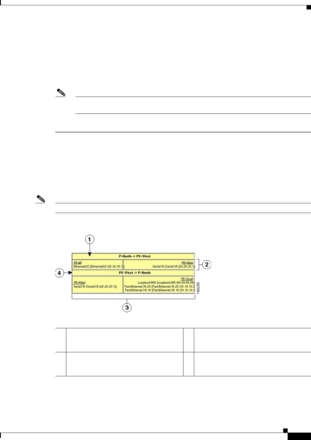
18-25
Cisco Prime Network 4.0 User Guide
OL-29343-01
Chapter 18 Monitoring MPLS Services Working with VPN Overlays
Managing a VPN Overlay Display in the Map View
After a VPN overlay is applied to a map, you can manage its display by using the overlay tools in the
main toolbar:
• To display the overlay, click Show Overlay on the main toolbar.
• To hide an active overlay, click Hide Overlay on the main toolbar.
Note The Show Overlay button is a toggle. When clicked, the overlay is displayed. When clicked
again, the overlay is hidden.
• To remove the VPN overlay, choose Show Overlay Type > None.
Displaying VPN Callouts in a VPN Overlay
You can display or hide the callouts for VPN links displayed in a VPN overlay to show the details of the
sites that are interlinked through the selected links. The callouts (see Figure 18-13) enable you to view
the VPN traffic links for a specific link (either bidirectional or unidirectional).
Note The link must be displayed in the VPN overlay and not dimmed for you to display the link callouts.
Figure 18-13 Callouts Window
1Link details and direction. In this example, the
link is from P-North to PE-West. 3Details of sites using the link and interlinks.
In this example, the site PE-West is linked to
all sites on PE-South.
2Details of the sites using the link and
interlinks. In this example, the site PE-88 is
linked to site PE-West.
4Link details and the direction. In this example,
the link is from PE-West to P-North.

18-26
Cisco Prime Network 4.0 User Guide OL-29343-01
Chapter 18 Monitoring MPLS Services
Monitoring MPLS Services
To display or hide the callouts:
Step 1 In the Prime Network Vision window, display the map view with the VPN overlay.
Step 2 Right-click the required link in the map view and choose Show Callouts.
Step 3 To hide the callouts, right-click the link in the map view that is displaying the callouts and choose Hide
Callouts.
Monitoring MPLS Services
The following topics provide details for viewing MPLS services and technologies:
• Viewing VPN Properties, page 18-26
• Viewing Site Properties, page 18-27
• Viewing VRF Properties, page 18-27
• Viewing VRF Egress and Ingress Adjacents, page 18-31
• Viewing Routing Entities, page 18-31
• Viewing Label Switched Entity Properties, page 18-39
• Viewing MP-BGP Information, page 18-45
• Viewing BFD Session Properties, page 18-47
• Viewing Cross-VRF Routing Entries, page 18-49
• Viewing Pseudowire End-to-End Emulation Tunnels, page 18-50
• Viewing MPLS TE Tunnel Information, page 18-52
Viewing VPN Properties
To view the properties of a VPN:
Step 1 In the Prime Network Vision navigation pane or map view, do either of the following:
• If the VPN icon is of the largest size, click the Properties button.
• Right-click the VPN and choose Properties.
The VPN Properties window displays the following information:
• Name—Name of the VPN.
• ID—Unique identifier assigned to the VPN.
Step 2 Click Close to close the VPN Properties dialog box.

18-27
Cisco Prime Network 4.0 User Guide
OL-29343-01
Chapter 18 Monitoring MPLS Services Monitoring MPLS Services
Viewing Site Properties
Prime Network Vision enables you to view site properties, including the interfaces that are configured
on the PE device. The displayed properties reflect the configuration that Prime Network Vision
automatically discovered for the device.
To view site properties, in the Prime Network Vision navigation pane or map view, right-click the
required site and choose Properties.
Table 18-8 describes the information that is displayed in the Router IP Interface Properties window:
Viewing VRF Properties
Prime Network Vision enables you to view VRF properties, including the VRF route distinguisher,
import and export route targets, and any provisioned sites and VRF routes.
To view VRF properties, do either of the following in map view:
• Double-click the element configured for VRFs.
• Expand the required VPN and double-click the virtual router.
Table 18-8 Router IP Interface Properties Window for Sites
Field Description
Name Name of the site, such as FastEthernet4/1.252.
State Interface state, either Up or Down.
IP Address IP address of the interface.
Mask Network mask.
Interface Description Description applied to the interface.
Associated Entity Element and interface associated with the site, hyperlinked to its
entry in physical inventory.
Addresses Table
Subnet IP address and subnet mask.
Note If the site is an IPv6 VPN over MPLS with IPv6 addresses
provisioned, the IPv6 addresses are displayed. For more
information, see Viewing IPv6 Information, page 17-2.
Type Address type, such as Primary, Secondary, or IPv6 Unicast.
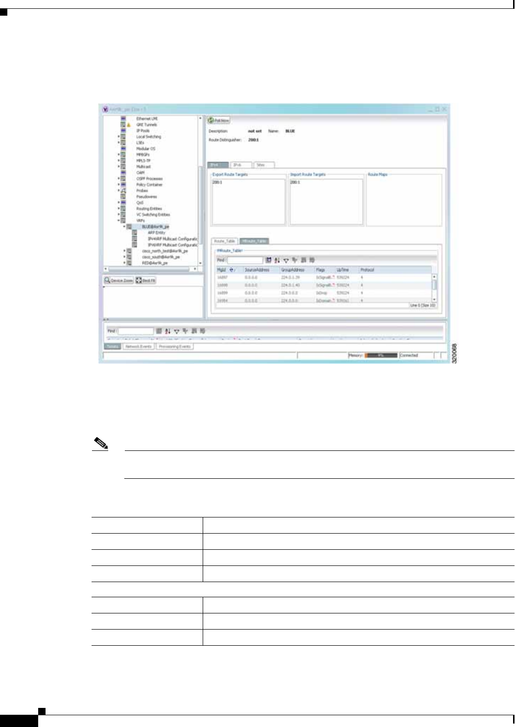
18-28
Cisco Prime Network 4.0 User Guide OL-29343-01
Chapter 18 Monitoring MPLS Services
Monitoring MPLS Services
The VRF properties window is displayed as shown in Figure 18-14.
Figure 18-14 VRF Properties
The VRF Properties window contains the VRF routing table for the device. The table is a collection of
routes that are available or reachable to all the destinations or networks in the VRF. The forwarding table
also contains MPLS encapsulation information.
Table 18-9 describes the information displayed in the VRF Properties window.
Note The VRF Properties window only displays properties and attributes that are provisioned in the
VRF. You might not see all the fields and tabs described in Table 18-9.
Table 18-9 VRF Properties
Field Description
Route Distinguisher Route distinguisher configured in the VRF.
Name VRF name.
Description Description of the VRF.
IPv4 Tab
Export Route Targets IPv4 export route targets contained by the VRF.
Import Route Targets IPv4 import route targets contained by the VRF.
Route Maps Route maps for the VRF.

18-29
Cisco Prime Network 4.0 User Guide
OL-29343-01
Chapter 18 Monitoring MPLS Services Monitoring MPLS Services
IPv6 Tab
Export Route Targets IPv6 export route targets contained by the VRF.
Import Route Targets IPv6 import route targets contained by the VRF.
Route Maps Route maps for the VRF.
Routing Tables
Destination Destination of the specific network.
Prefix Length Length of the network prefix in bits.
Next Hop Next routing hop.
Outgoing Interface Name of the outgoing interface; displayed if the Routing Protocol type is
local.
Type Route type: Direct (local), Indirect, or Static.
Routing Protocol Routing protocol used to communicate with the other sites and VRFs: BGP
or local.
BGP Next Hop Border Gateway Protocol (BGP) next hop. This is the PE address from
which to continue to get to a specific address. This field is empty when the
routing entry goes to the CE.
Bottom In Label Innermost label that is expected when MPLS traffic is received.
Bottom Out Label Innermost label sent with MPLS traffic.
Outer Label Outermost or top label in the stack used for MPLS traffic.
MRoute_Table
Source Address The source IP address from where the multicast information is sent.
Group Address The group IP address of the multicast.
Flags The flag information pertaining to the multicast.
Up Time The amount of time the interface has been active.
Protocol The protocol information, which can be 4 or 6.
Sites Tab
Name Site name.
IP Address IP address of the interface.
Mask Subnet mask.
State State of the subinterface: Up or Down.
Associated Entity Element and interface associated with the site, hyperlinked to its entry in
physical inventory.
Description Interface description.
Input Access List Access list applied to the inbound traffic.
Output Access List Access list applied to the outbound traffic.
Table 18-9 VRF Properties (continued)
Field Description

18-30
Cisco Prime Network 4.0 User Guide OL-29343-01
Chapter 18 Monitoring MPLS Services
Monitoring MPLS Services
Viewing VRF Multicast Configuration details
To view global multicast configuration details for a VRF:
Step 1 Right-click on the required device and select Inventory.
Step 2 In the Inventory window, choose Logical Inventory > VRFs > vrf (where vrf is the required
VRF) > IPV4VRF Multicast Configuration or IPV6VRF Multicast Configuration. The route
policies configured on the device are displayed in the content pane.
Table 18-10 describes the information that is displayed in the Router IP Interface Properties window:
Rate Limits If a rate limit is configured on an IP interface, the limit is shown as an IP
interface property. This option is checked when a rate limit is defined on
the IP interface, meaning the access list is a rate limit access list. IP
interface traffic is measured and includes the average rate, normal burst
size, excess burst size, conform action, and exceed action.
Note Double-clicking a row displays the properties of the IP interface.
When a rate limit is configured on the IP interface, the Rate Limits
tab is displayed. For more information about rate limits, see
Viewing Rate Limit Information, page 18-36.
Note The Input Access, Output Access, and Rate Limits parameters
apply only to Cisco IOS devices.
IP Sec Map Name IP Security (IPsec) map name.
Site Name Name of the business element to which the interface is attached.
Table 18-9 VRF Properties (continued)
Field Description
Table 18-10 Global Multicast Configuration Details
Field Description
VPN ID The VPN ID configured for the VRF.
RoutePolicy The name of the multicast route policy.
BgpAD The BgpAd enabled on the device.
MdtSourceif The Multicast Distribution Tree (MDT) source interface.
MdtPartioned The MDT partitioned permission.
NSF The non-stop forwarding (NSF) information configured for the
VRF.
MdtAddress The MDT address.
MdtData The MDT data that can be handled.
Address Family The address family, which can be IPV4 or IPV6.
RP Address The rendezvous point (RP) address configured for the VRF.

18-31
Cisco Prime Network 4.0 User Guide
OL-29343-01
Chapter 18 Monitoring MPLS Services Monitoring MPLS Services
Viewing VRF Egress and Ingress Adjacents
Prime Network Vision enables you to view the exporting and importing neighbors by displaying the VRF
egress and ingress adjacents. In addition, you can view the connectivity between the VRFs for the route
targets and view their properties. For example, if VRF A retrieved route target import X, you can view
all VRFs that export X as a route target whether it is in the same or another VPN.
To display the VRF egress and ingress adjacents, you can use either an element configured for VRFs or
a virtual router:
• To use an element configured for VRFs:
a. Double-click the element configured for VRFs.
b. In the inventory window, choose Logical Inventory > VRFs > vrf where vrf is the required
VRF.
c. Right-click the required VRF and choose Show VRF Egress Adjacents or Show VRF Ingress
Adjacents.
• To use a virtual router, right-click the required VRF in the navigation pane, and choose Show VRF
Egress Adjacents or Show VRF Ingress Adjacents.
Table 18-11 describes the information displayed in the Adjacents window.
Viewing Routing Entities
To view routing entities:
Step 1 Right-click the required device in Prime Network Vision and choose Inventory.
Step 2 In the logical inventory window, choose Logical Inventory > Routing Entities > Routing Entity.
The routing information is displayed as shown in Figure 18-15.
Table 18-11 VRF Adjacents Properties Window
Field Description
Name VRF name.
Route Distinguisher Route distinguisher configured in the VRF.
VRF V6 Table IPv6 route distinguisher if IPv6 is configured.
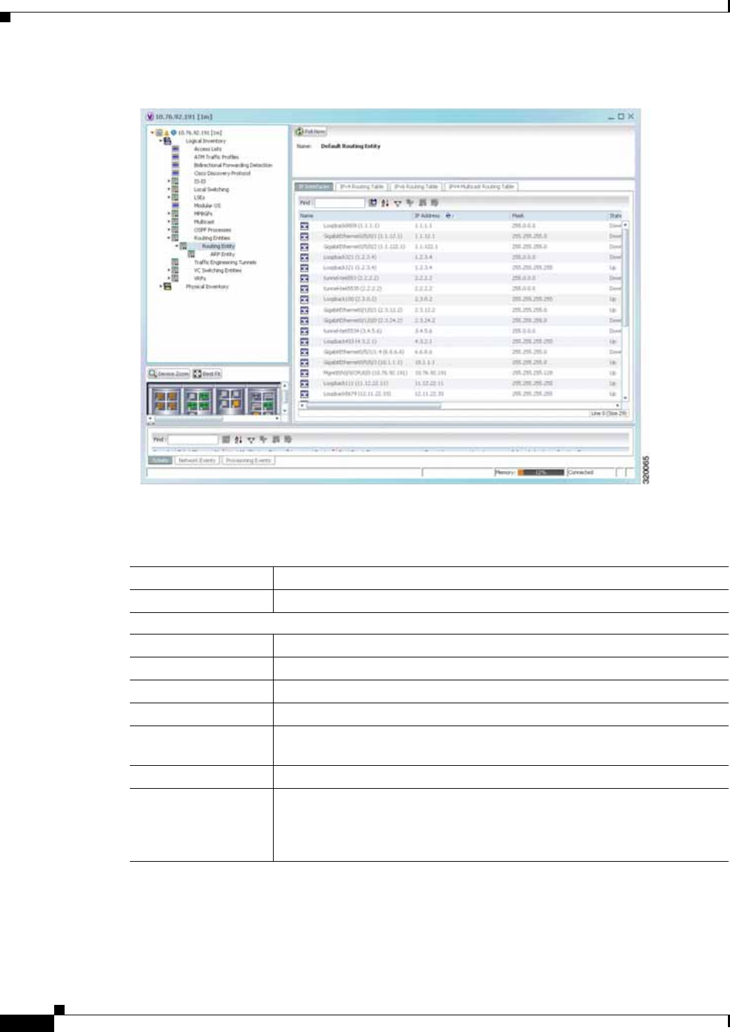
18-32
Cisco Prime Network 4.0 User Guide OL-29343-01
Chapter 18 Monitoring MPLS Services
Monitoring MPLS Services
Figure 18-15 Routing Entity Table
Table 18-12 describes the information that is displayed in the Routing Entity table.
Table 18-12 Routing Entity Table
Field Description
Name Name of the routing entity.
IP Interfaces Tab
Name Site name.
IP Address IP address of the interface.
Mask Network mask.
State State of the subinterface: Up or Down.
Associated Entity Interface associated with the routing entity, hyperlinked to its location in
physical inventory.
Description Description of the interface.
Input Access List If an input access list is assigned to an IP interface, the list is shown as an IP
interface property, and a hyperlink highlights the related access list in the
Access List table. When an access list is assigned to the inbound traffic on an
IP interface, the actions assigned to the packet are performed.

18-33
Cisco Prime Network 4.0 User Guide
OL-29343-01
Chapter 18 Monitoring MPLS Services Monitoring MPLS Services
VRRP Group If a VRRP group is configured on an IP interface, the information is shown
as an IP interface property. This option is checked when a rate limit is defined
on the IP interface.
Note Double-clicking a row displays the properties of the IP interface.
When a VRRP group is configured on an IP interface, the VRRP
Groups tab is displayed in the IP Interface Properties window. For
more information, see Viewing VRRP Information, page 18-37.
Output Access List If an output access list is assigned to an IP interface, the list is shown as an
IP interface property, and a hyperlink highlights the related access list in the
Access List table. When an access list is assigned to the outbound traffic on
an IP interface, the actions assigned to the packet are performed.
Rate Limits If a rate limit is configured on an IP interface, the limit is shown as an IP
interface property. This option is checked when a rate limit is defined on the
IP interface, meaning the access list is a rate limit access list. IP interface
traffic is measured and includes the average rate, normal burst size, excess
burst size, conform action, and exceed action.
Note Double-clicking a row displays the properties of the IP interface.
When a rate limit is configured on the IP interface, the Rate Limits
tab is displayed. For more information, see Viewing Rate Limit
Information, page 18-36.
Note The Input Access, Output Access, and Rate Limits parameters apply
only to Cisco IOS devices.
IP Sec Map Name IP Security (IPsec) crypto map name.
Site Name Name of the business element to which the interface is attached.
IPv4 and IPv6 Routing Table Tabs
Destination Destination of the specific network.
Outgoing If Name Name of the outgoing interface.
Type Routing type: Direct, Indirect, Static, Other, Invalid, or Unknown.
Next Hop IP address from which to continue to get to a specific address. This field is
empty when the routing entry goes to a PE router.
Prefix Length Length of the network prefix in bits.
Route Protocol Type Routing protocol used to communicate with other routers.
IPv4 and IPv6 Multicast Routing Tabs
Source Address The source IP address from where the multicast information is sent.
Group Address The group IP address of the multicast.
Flags The flag information pertaining to the multicast.
Up Time The amount of time the interface has been active.
Protocol The protocol information, which can be 4 or 6.
Table 18-12 Routing Entity Table (continued)
Field Description

18-34
Cisco Prime Network 4.0 User Guide OL-29343-01
Chapter 18 Monitoring MPLS Services
Monitoring MPLS Services
Viewing the ARP Table
To view the ARP table:
Step 1 Right-click the required device in Prime Network Vision and choose Inventory.
Step 2 In the logical inventory window, choose Logical Inventory > Routing Entities > Routing
Entity > ARP.
Table 18-13 describes the information that is displayed in the ARP table.
Viewing the NDP Table
Neighbor Discovery Protocol (NDP) is used with IPv6 to discover other nodes, determine the link layer
addresses of other nodes, find available routers, and maintain reachability information about the paths
to other active neighbor nodes.
NDP functionality includes:
• Router discovery
• Autoconfiguration of addresses (stateless address autoconfiguration [SLAAC])
• IPv6 address resolution (replaces Address Resolution Protocol [ARP])
• Neighbor reachability (neighbor unreachability detection [NUD])
• Duplicate address detection (DAD)
• Redirection
Table 18-13 ARP Table
Field Description
MAC Interface MAC address.
Interface Interface name.
IP Address Interface IP address.
State Interface state:
• Dynamic—The entry was learned by the device according to
network traffic.
• Static—The entry was learned by a local interface or from a user
configuring a static route.
• Other—The entry was learned by another method not explicitly
defined.
• Invalid—In SNMP, this type is used to remove an ARP entry from
the table.
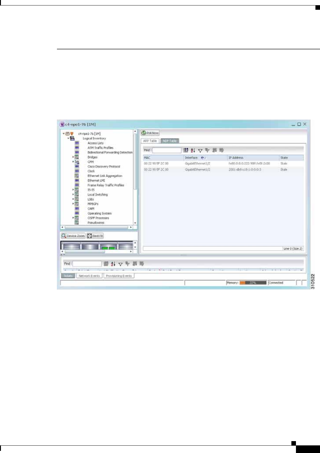
18-35
Cisco Prime Network 4.0 User Guide
OL-29343-01
Chapter 18 Monitoring MPLS Services Monitoring MPLS Services
To view the NDP table:
Step 1 Right-click the required device in Prime Network Vision and choose Inventory.
Step 2 In the logical inventory window, choose Logical Inventory > Routing Entities > Routing
Entity > ARP Entity.
Step 3 Click the NDP Table tab.
Figure 18-16 shows an example of the NDP Table tab.
Figure 18-16 NDP Table in Logical Inventory
Table 18-14 describes the information displayed for NDP.

18-36
Cisco Prime Network 4.0 User Guide OL-29343-01
Chapter 18 Monitoring MPLS Services
Monitoring MPLS Services
Viewing Rate Limit Information
To view rate limit information:
Step 1 Right-click the required element in Prime Network Vision and choose Inventory.
Step 2 In the logical inventory window, choose Logical Inventory > Routing Entities > Routing Entity.
Step 3 In the IP Interfaces tab, double-click the required interface to view the IP interface properties. If a rate
limit is configured on the IP interface, the Rate Limits tab is displayed.
Note Rate limit information is relevant only for Cisco IOS devices.
Table 18-14 NDP Table
Field Description
MAC Interface MAC address.
Interface Interface name.
IP Address Interface IPv6 address.
Type Entry type:
• ICMP (Incomplete)—Address resolution is being performed on the
entry. A neighbor solicitation (NS) message has been sent to the
solicited-node multicast address of the target, but the corresponding
neighbor advertisement (NA) message has not yet been received.
• REACH (Reachable)—Positive confirmation was received via an
NA that the forward path to the neighbor was functioning properly.
While in REACH state, the device takes no special action as packets
are sent.
• STALE—Too much time has elapsed since the last positive
confirmation was received that the forward path was functioning
properly. While in STALE state, the device takes no action until a
packet is sent.
• DELAY—Too much time has elapsed since the last positive
confirmation was received that the forward path was functioning
properly. If no reachability confirmation is received within a
specified amount of time, the device sends an NS message and
changes the state to PROBE.
• PROBE—A reachability confirmation is actively sought by
resending neighbor solicitation messages until a reachability
confirmation is received.

18-37
Cisco Prime Network 4.0 User Guide
OL-29343-01
Chapter 18 Monitoring MPLS Services Monitoring MPLS Services
Table 18-15 describes the information that is displayed in the Rate Limits tab of the IP Interface
Properties dialog box.
Viewing VRRP Information
Virtual Router Redundancy Protocol (VRRP) is a non-proprietary redundancy protocol that is designed
to increase the availability of the static default gateway servicing hosts on the same subnet. This
increased reliability is achieved by advertising a virtual router (a representation of master and backup
routers acting as a group) as a default gateway to the hosts instead of one physical router. Two or more
physical routers are then configured to stand for the virtual router, with only one doing the actual routing
at any given time. If the current physical router that is routing the data on behalf of the virtual router
fails, another physical router automatically replaces it. The physical router that forwards data on behalf
of the virtual router is called the master router; physical routers standing by to take over for the master
router if needed are called backup routers.
To view VRRP information:
Step 1 Double-click the required element in Prime Network Vision.
Step 2 In logical inventory, choose Logical Inventory > Routing Entities > Routing Entity.
Step 3 In the IP Interfaces tab, double-click the required interface to view the IP interface properties. If VRRP
is configured on the IP interface, the VRRP Groups tab is displayed.
Table 18-15 Rate Limits Information
Field Description
Type Rate limit direction, either Input or Output.
Max Burst Excess burst size in bytes.
Normal Burst Normal burst size in bytes.
Bit Per Second Average rate in bits per second.
Conform Action Action that can be performed on the packet if it conforms to the specified
rate limit (rule), for example, continue, drop, change a bit, or transmit.
Exceed Action Action that can be performed on the packet if it exceeds the specified rate
limit (rule), for example, continue, drop, change a bit, or transmit.
Access List Hyperlink that highlights the related access list in the Access List table.
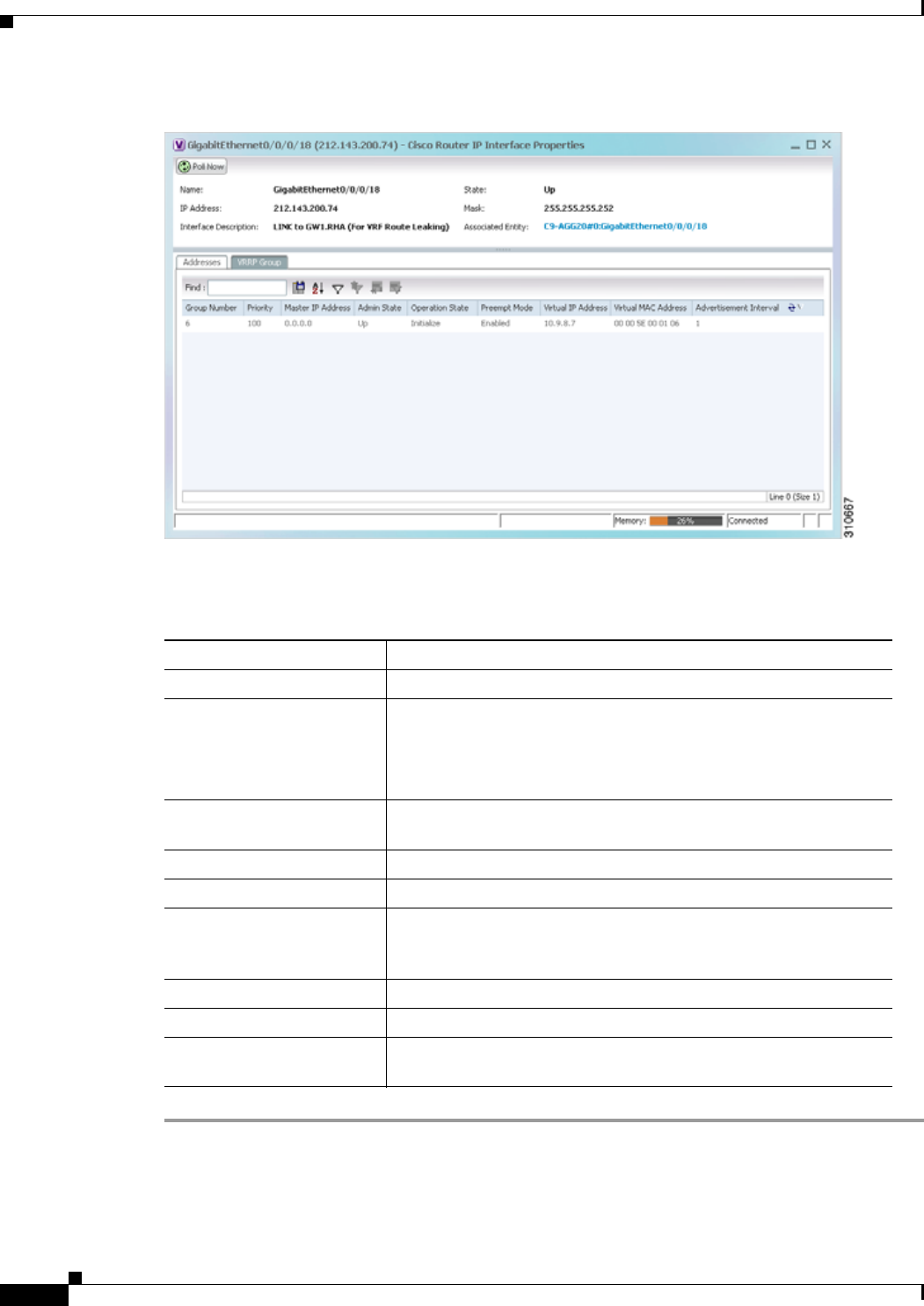
18-38
Cisco Prime Network 4.0 User Guide OL-29343-01
Chapter 18 Monitoring MPLS Services
Monitoring MPLS Services
Figure 18-17 VRRP Properties in IP Interface Properties Window
Table 18-16 describes the information in the VRRP Groups tab.
Table 18-16 VRRP Group Properties
Field Description
Group Number Number of the VRRP group associated with the interface.
Priority Value that determines the role each VRRP router plays and what
happens if the master virtual router fails.
Values are 1 through 254, with lower numbers having priority over
higher numbers.
Master IP Address IP address of the VRRP group, taken from the physical Ethernet
address of the master virtual router.
Admin State Administrative status of the VRRP group: Up or Down.
Operation State State of the VRRP group: Master or Backup.
Preempt Mode Whether or not the router is to take over as the master virtual router
for a VRRP group if it has a higher priority than the current master
virtual router: Enabled or Disabled.
Virtual IP Address IP address of the virtual router.
Virtual MAC Address MAC address of the virtual router.
Advertisement Interval Amount of time (in seconds) between successive advertisements by
the master virtual router.

18-39
Cisco Prime Network 4.0 User Guide
OL-29343-01
Chapter 18 Monitoring MPLS Services Monitoring MPLS Services
Viewing Label Switched Entity Properties
Logical inventory can display any or all of the following tabs for label switched entities, depending on
the configuration:
• Label Switching Table—Describes the MPLS label switching entries used for traversing MPLS core
networks.
• LDP Neighbors—Details all MPLS interface peers that use the Label Distribution Protocol (LDP).
LDP enables neighboring provider (P) or PE routers acting as label switch routers (LSRs) in an
MPLS-aware network to exchange label prefix binding information, which is required to forwarding
traffic. The LSRs discover potential peers in the network with which they can establish LDP sessions
in order to negotiate and exchange the labels (addresses) to be used for forwarding packets.
Two LDP peer discovery types are supported:
–
Basic discovery—Used to discover directly connected LDP LSRs. An LSR sends hello
messages to the all-routers-on-this-subnet multicast address, on interfaces for which LDP has
been configured.
–
Extended discovery—Used between indirectly connected LDP LSRs. An LSR sends targeted
hello messages to specific IP addresses. Targeted sessions are configured because the routers
are not physically connected, and broadcasting would not reach the peers. The IP addresses of
both peers are required for extended discovery.
If two LSRs are connected with two separate interfaces, two LDP discoveries are performed.
• MPLS Interfaces—Contains information on MPLS interfaces and whether traffic engineering
tunnels are configured on an interface.
• MPLS Label Range—Identifies whether MPLS uses static or dynamic routing, and the label range.
• Traffic Engineering LSPs—Describes the MPLS traffic engineering Label Switched Paths (LSPs)
provisioned on the switch entity. MPLS traffic engineering LSP, an extension to MPLS TE, provides
flexibility when configuring LSP attributes for MPLS TE tunnels.
• VRF Table—Describes MPLS paths that terminate locally at a VRF.
To view information for label switched entities:
Step 1 Double-click the required device in Prime Network Vision.
Step 2 In the logical inventory window, choose Logical Inventory > LSEs > Label Switching.
Table 18-17 describes the information that is displayed for label switched entities.
Table 18-17 Label Switching Properties in Logical Inventory
Field Description
Local LDP ID Local Label Distribution Protocol (LDP) identifier.
LDP Process State State of the LDP process, such as Running, Down, or Unknown.
MPLS Interfaces
ID Identifier for MPLS interface, as a combination of IP address and
interface name.
Distribution Protocol Type Distribution protocol used: Null, LDP, TDP (Tag Distribution
Protocol), RSVP, or TDP and LDP.

18-40
Cisco Prime Network 4.0 User Guide OL-29343-01
Chapter 18 Monitoring MPLS Services
Monitoring MPLS Services
MPLS TE Properties Whether or not traffic engineering (TE) properties are configured on
the interface:
• Checked—MPLS TE properties are configured on the interface.
• Unchecked—MPLS TE properties are not configured on the
interface.
Discovery Protocols Discovery protocols used on the interface.
Label Switching Table
Incoming Label Incoming MPLS label identifier.
Action Type of switching action: Null, Pop, Swap, Aggregate, Untagged, or
Act. If an action is defined as Pop, an outgoing label is not required.
If an action is defined as Untagged, an outgoing label is not present.
Outgoing Label Outgoing label.
Out Interface Name of the outgoing interface, displayed as a hyperlink to the port
subinterface in physical inventory.
IP Destination Destination IP address.
Destination Mask Subnet mask of the destination.
Next Hop IP address of the next hop in the path. The IP address is used for
resolving the MAC address of the next MPLS interface that you
want to reach.
VRF Table
Incoming Label Incoming VRF label identifier.
Action Type of switching action: Null, Pop, Swap, Aggregate, Untagged, or
Act.
VRF VRF name, hyperlinked to its location in logical inventory.
IP Destination Destination IP address.
Destination Mask Subnet mask of the destination.
Next Hop IP address of the next hop in the path. The IP address is used for
resolving the MAC address of the next MPLS interface that you
want to reach.
Out Interface Name of the outgoing interface, displayed as a hyperlink to the port
subinterface in physical inventory.
Traffic Engineering LSPs
LSP Name Label switched path (LSP) name.
LSP Type Segment type: Head, Midpoint, or Tail.
Source Address Source IP address.
Destination Address Destination IP address.
In Label Incoming label, if not a head segment.
In Interface Incoming interface, if not a head segment.
Out Interface Outgoing interface, if not a tail segment.
Table 18-17 Label Switching Properties in Logical Inventory (continued)
Field Description

18-41
Cisco Prime Network 4.0 User Guide
OL-29343-01
Chapter 18 Monitoring MPLS Services Monitoring MPLS Services
Out Label Outgoing label, if not a tail segment.
Average Bandwidth (Kbps) Current bandwidth (in Kb/s) used to automatically allocate the
tunnel’s bandwidth.
LSP ID LSP identifier.
Burst (Kbps) Tunnel bandwidth burst rate, in Kb/s.
Peak (Kbps) Tunnel bandwidth peak rate, in Kb/s.
FRR TE Tunnel Fast Reroute (FRR) TE tunnel name, hyperlinked to the routing
entity in logical inventory.
FRR TE Tunnel State State of the FRR TE tunnel:
• Active—A failure exists in the primary tunnel and the backup
is in use.
• Not Configured—The primary tunnel has no designated backup
tunnel.
• Ready—The primary tunnel is in working condition.
MPLS Label Range
MPLS Label Type Type of MPLS label: Dynamic or Static.
Minimum Label Value Lowest acceptable MPLS label in the range.
Maximum Label Value Highest acceptable MPLS label in the range.
LDP Neighbors
LDP ID Identifier of the LDP peer.
Transport IP Address IP address advertised by the peer in the hello message or the hello
source address.
Session State Current state of the session: Transient, Initialized, Open Rec, Open
Sent, or Operational.
Protocol Type Protocol used by the peer to establish the session: LDP, TDP, or
Unknown.
Label Distribution Method Method of label distribution: Downstream, Downstream On
Demand, Downstream Unsolicited, or Unknown.
Session Keepalive Interval Length of time (in milliseconds) between keepalive messages.
Session Hold Time The amount of time (in milliseconds) that an LDP session can be
maintained with an LDP peer, without receiving LDP traffic or an
LDP keepalive message from the peer.
Discovery Sources Whether the peer has one or more discovery sources:
• Checked—Has one or more discovery sources.
• Unchecked—Has no discovery sources.
Note To see the discovery sources in the LDP Neighbor
Properties window, double-click the row of the peer in the
table.
Table 18-17 Label Switching Properties in Logical Inventory (continued)
Field Description

18-42
Cisco Prime Network 4.0 User Guide OL-29343-01
Chapter 18 Monitoring MPLS Services
Monitoring MPLS Services
Step 3 Double-click an entry in any of the tables to view additional properties for that entry.
Multicast Label Switching (mLADP)
Multicast Label Distribution protocol (mLDP) provides extensions to the Label Distribution Protocol
(LDP) for the setup of point-to-multipoint (P2MP) and multipoint-to-multipoint (MP2MP) Label
Switched Paths (LSPs) in MultiProtocol Label Switching (MPLS) networks. A P2MP LSP allows traffic
from a single root (or ingress) node to be delivered to a number of leaf (or egress) nodes.
A MP2MP LSP allows traffic from multiple ingress nodes to be delivered to multiple egress nodes. Only
a single copy of the packet will be sent on any link traversed by a multipoint LSP. Container is the holder
of MPLS MLDP databases and neighbors instances for Multicast.
Viewing MLDP Database Information
To view the MLDP database information:
Step 1 Double-click the required device in Prime Network Vision.
Step 2 In the logical inventory window, choose Logical Inventory > LSEs > Label Switching > Multicast
Label Switching > Databases. The database information is displayed in the MLDP Databases content
pane.
Step 3 Select a database from the content pane, right-click and choose the Properties option. The MLDP
Database Properties dialog box is displayed. You can click on the tabs to view more details.
Table 18-19 describes the information that is displayed for MLDP Database Properties dialog box.
Table 18-18 Additional Properties Available from Label Switching in Logical Inventory
Double-click an entry in this tab... To display this window...
Label Switching Table Label Switching Properties
LDP Neighbors LDP Peer Properties
MPLS Interfaces MPLS Link Information - MPLS Properties
MPLS Label Range MPLS Label Range Properties
Traffic Engineering LSPs Tunnel Properties
VRF Table MPLS Aggregate Entry Properties

18-43
Cisco Prime Network 4.0 User Guide
OL-29343-01
Chapter 18 Monitoring MPLS Services Monitoring MPLS Services
Viewing the MLDP Neighbors Information
To view information of MLDP neighbors:
Step 1 Double-click the required device in Prime Network Vision.
Step 2 In the logical inventory window, choose Logical Inventory > LSEs > Label Switching > Multicast
Label Switching > MLDP Neighbors. The MLDP peer information is displayed in the MLDP Peers
content pane.
Step 3 Select a peer id from the content pane, right-click and choose the Properties option. The Peer ID
Properties dialog box is displayed.
Table 18-20 describes the information that is displayed for Peer ID Properties dialog box.
Table 18-19 MLDP Database Properties Dialog Box
Field Description
LSM ID The unique ID assigned to a LSP.
Tunnel Type The tunnel type.
FEC Root The root IP address of the MDT.
Opaque Value The stream information that uniquely identifies the tree to the root.
To receive label switched multicast packets, the Egress Provider
Edge (PE) indicates to the upstream router (the next hop closest to
the root) which label it uses for the multicast source by applying the
label mapping message.
Is Root Indicates whether Forwarding Equivalence Class (FEC) is the root.
Downstream Clients Tab
Egress Interface Name The egress interface name.
Associated Entity The entity associated with the LSP. Click this link to view the
associated entity details.
Uptime The amount of time from when the interface is active.
Table ID The unique Table ID of the label through which the packet was
received.
Ingress State The status of the ingress interface, which can be Enabled or
Disabled.
PPMP State The status of the Point-to-Point Multipoint, which can be Enabled
or Disabled.
Local Label The label used to identify the label stack of the route within the local
VPN network.

18-44
Cisco Prime Network 4.0 User Guide OL-29343-01
Chapter 18 Monitoring MPLS Services
Monitoring MPLS Services
Table 18-20 Peer ID Properties Dialog Box
Field Description
Peer ID The IP address of the MLDP peer.
Capabilities The capabilities supported by the LDP LSR.
MLDP GR Indicates whether graceful restart is enabled for the LDP.
Note LDP graceful restart provides a control plane mechanism to
ensure high availability and allows detection and recovery
from failure conditions while preserving Non Stop
Forwarding (NSF) services.
Path Count The number of LSP’s configured.
Uptime The amount of time from when the peer id is working.
Peer Paths tab
IP Address The IP address of the MLDP peer.
Interface Name The interface name.
Associated Entity The link to the associated entity, which when clicked will highlight
the associated Default routing entity record under the Routing
Entity node.
Protocol The protocol type used for communication.
Peer Adjacent List
IP Address The IP address of the MLDP peer.
Interface Name The interface name.
Associated Entity The link to the associated entity, which when clicked will highlight
the associated Default routing entity record under the Routing
Entity node.

18-45
Cisco Prime Network 4.0 User Guide
OL-29343-01
Chapter 18 Monitoring MPLS Services Monitoring MPLS Services
Viewing MP-BGP Information
The MP-BGP branch displays information about a router’s BGP neighbors and cross-connect VRFs.
Note If there are multiple MP-BGP links between two devices, Prime Network displays each link in the content
pane map view.
To view MP-BGP information:
Step 1 Right-click the required device in Prime Network Vision and choose Inventory.
Step 2 In the logical inventory window, choose Logical Inventory > MPBGPs > MPBGP.
Table 18-21 describes the information that is displayed for MP-BGP.
Table 18-21 MP-BGP Information in Logical Inventory
Field Description
Local AS Identifier of the autonomous system (AS) to which the router
belongs.
BGP Identifier BGP identifier, represented as an IP address.
Cross VRFs Tab
VRF Name Name of the VRF.
Cross VRF Routing Entries Group of cross VRFs that share a single destination.
BGP Neighbors Tab
Peer AS Identifier of the AS to which the remote peer belongs.
Peer State State of the remote peer: Active, Connect, Established, Open
Confirm, Open Sent, or Null.
Peer Address Remote peer IP address.
AFI Address family identifier: IPv4, IPv6, L2VPN, VPNv4, or VPNv6.
AF Peer State Address family peer state: Established or Idle.
Peer BGP ID Identifier of the remote peer, represented as an IP address.
Local BGP ID Local peer IP address.
VRF Name Remote peer VRF name.
BGP Neighbor Type Neighbor type: Null, Client, or Non Client.
Hold Time (secs) Established hold time in seconds.
Keepalive (secs) Established keepalive time in seconds.
BGP Neighbor Entry BGP neighbor IP address.
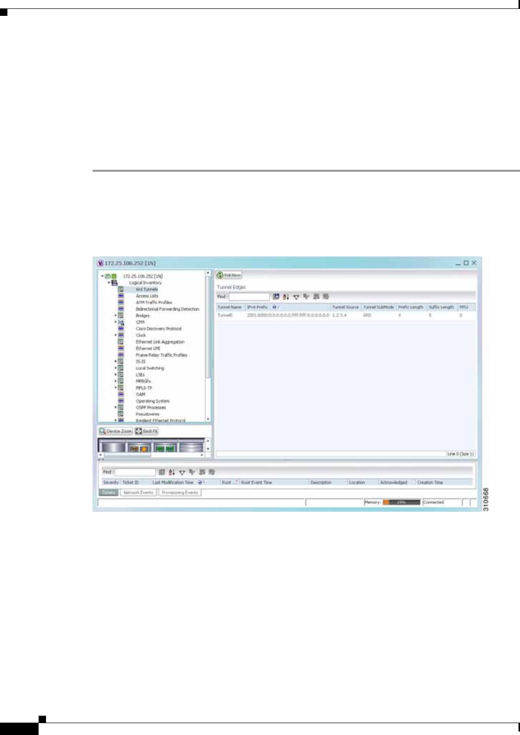
18-46
Cisco Prime Network 4.0 User Guide OL-29343-01
Chapter 18 Monitoring MPLS Services
Monitoring MPLS Services
Viewing 6rd Tunnel Properties
IPv6 rapid deployment (6rd) is a mechanism that allows stateless tunneling of IPv6 over IPv4. From
Prime Network Vision 3.8, 6rd is supported on the following devices:
• Cisco 7600 series devices
• Cisco ASR 1000 series devices
To view 6rd tunnel properties:
Step 1 In Prime Network Vision, double-click the required device.
Step 2 In the inventory window, choose Logical Inventory > 6rd Tunnels.
The 6rd tunnel properties are displayed as shown in Figure 18-18.
Figure 18-18 6rd Tunnel Properties in Logical Inventory
Table 18-22 describes the information displayed for 6rd tunnels.

18-47
Cisco Prime Network 4.0 User Guide
OL-29343-01
Chapter 18 Monitoring MPLS Services Monitoring MPLS Services
Viewing BFD Session Properties
Bidirectional Forwarding Detection (BFD) is used to detect communication failures between two
elements, or endpoints, that are connected by a link, such as a virtual circuit, tunnel, or LSP. BFD
establishes sessions between the two endpoints over the link. If more than one link exists, BFD
establishes a session for each link.
Prime Network Vision supports BFD with the following protocols: BGP, IPv4 (static), IPv6 (static),
IS-IS, LAG (Ether channel), MPLS TE, MPLS-TP, and OSPF.
To view BFD session properties that are configured on an element:
Step 1 In Prime Network Vision, double-click the required device.
Step 2 In the inventory window, choose Logical Inventory > Bidirectional Forwarding Detection.
The properties for BFD sessions are displayed as shown in Figure 18-19.
Table 18-22 6rd Tunnel Properties in Logical Inventory
Field Description
Tunnel Name 6rd tunnel name.
IPv6 Prefix IPv6 prefix used to translate the IPv4 address to an IPv6 address.
Source Address Tunnel IPv4 source IP address.
Tunnel SubMode Tunnel type:
• 6rd—Static IPv6 interface.
• 6to4—IPv6 address with the prefix embedding the tunnel
source IPv4 address.
• Auto-tunnel—IPv4-compatible IPv6 tunnel.
• ISATAP—Overlay tunnel using an Intra-Site Automatic Tunnel
Addressing Protocol (ISATAP) address.
Prefix Length IPv4 prefix length used to derive the delegated IPv6 prefix.
Suffix Length IPv4 suffix length used to derive the delegated IPv6 prefix.
MTU Maximum transmission unit (MTU) configured on the 6rd IPv4
tunnel.
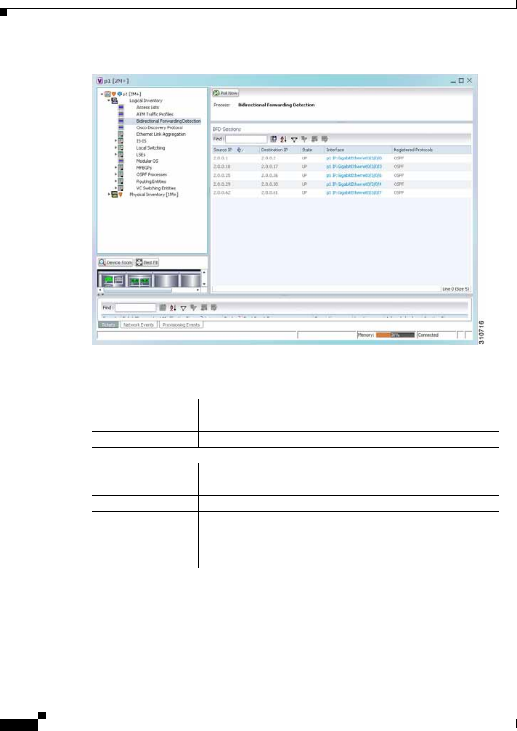
18-48
Cisco Prime Network 4.0 User Guide OL-29343-01
Chapter 18 Monitoring MPLS Services
Monitoring MPLS Services
Figure 18-19 BFD Session Properties
Table 18-23 describes the information displayed for BFD sessions.
Table 18-23 BFD Session Properties
Field Description
Process Process name, such as Bidirectional Forwarding Detection.
Process State Process state, such as Running.
BFD Sessions Table
Source IP Source IP address of the session.
Destination IP Destination IP address of the session.
State Session state, such as Up or Down.
Interface Interface used for BFD communications, hyperlinked to the routing
entity in logical inventory.
Registered Protocols Routing protocol being monitored for communication failures, such as
BGP or OSPF.

18-49
Cisco Prime Network 4.0 User Guide
OL-29343-01
Chapter 18 Monitoring MPLS Services Monitoring MPLS Services
For MPLS-TP BFD sessions, the information in Table 18-24 is displayed.
Step 3 To view additional properties, double-click the required entry in the Sessions table.
Table 18-25 describes the information that is displayed in the Session Properties window.
Viewing Cross-VRF Routing Entries
Cross-VRF routing entries display routing information learned from the BGP neighbors (BGP
knowledge base).
To view properties for cross-VRF routing entries:
Step 1 Right-click the required device in Prime Network Vision and choose Inventory.
Table 18-24 MPLS-TP BFD Session Properties in Logical Inventory
Field Description
Process Process name: Bidirectional Forwarding Detection.
Process State Process state, such as Running.
MPLS-TP BFD Sessions Table
Interface Interface used for BFD communications, hyperlinked to the routing
entity in logical inventory.
LSP Type Type of LSP: Working or Protected.
State Session state: Up or Down.
Registered Protocols Routing protocol being monitored for communication failures:
MPLS-TP.
Interface Name
Table 18-25 Session Properties Window
Field Description
Source IP Source IP address of the session.
Destination IP Destination IP address of the session.
State Session state: Up or Down.
Interface Hyperlink to the routing entity in logical inventory.
Registered Protocols Routing protocol being monitored for communication failures.
Protocols Table
Protocol Protocol used for this session.
Interval Length of time (in milliseconds) to wait between packets that are
sent to the neighbor.
Multiplier Number of times a packet is missed before the neighbor is declared
down.

18-50
Cisco Prime Network 4.0 User Guide OL-29343-01
Chapter 18 Monitoring MPLS Services
Monitoring MPLS Services
Step 2 In the logical inventory window, choose Logical Inventory > MPBGPs > MPBGP.
Step 3 Click the Cross VRFs tab.
Step 4 Double-click the required entry in the list of cross-VRFs.
The Cross VRF Properties window is displayed, containing the information described in Table 18-26.
Viewing Pseudowire End-to-End Emulation Tunnels
The Pseudowires branch in logical inventory displays a list of the Layer 2 tunnel edge properties (per
edge), including tunnel status and VC labels.
To view pseudowire properties:
Step 1 Right-click the required device in Prime Network Vision and choose Inventory.
Step 2 In the logical inventory window, choose Logical Inventory > Pseudowires.
The Tunnel Edges table is displayed and contains the information described in Table 18-27.
Table 18-26 Cross-VRF Properties Window
Field Description
Name Cross-VRF name.
Cross VRF Routing Entries Table
Destination IP address of the destination network.
Prefix Length of the network prefix in bits.
Next Hop IP address of the next hop in the path.
Out Going VRF Outgoing VRF identifier, hyperlinked to its entry in logical inventory.
Out Tag Outgoing virtual router tag, such as 50 or no tag.
In Tag Incoming virtual router tag, such as 97 or no tag.

18-51
Cisco Prime Network 4.0 User Guide
OL-29343-01
Chapter 18 Monitoring MPLS Services Monitoring MPLS Services
Table 18-27 Pseudowires Branch Tunnel Edges Table
Field Description
Local Interface Name of the subinterface or port.
Strings, such as Aggregation Group, EFP, VLAN, and VSI, are included in the interface name, and
the entry is hyperlinked to the relevant entry in logical or physical inventory:
• Aggregation groups are linked to Ethernet Link Aggregation in logical inventory.
• ATM interfaces are linked to the port in physical inventory and the ATM interface.
• ATM VCs are linked to the port in physical inventory and the Port IP Properties table.
• CEM groups are linked to the port in physical inventory and the CEM Group table.
• EFPs are linked to the port in physical inventory and the EFPs table.
• IMA groups are linked to IMA Groups in logical inventory.
• Local switching entities are linked to Local Switching Entity in logical inventory.
• VLANs are linked to Bridges in logical inventory.
• VSIs are linked to the VSI entry in logical inventory.
VC ID Tunnel identifier, hyperlinked to the PTP Layer 2 MPLS Tunnel Properties window.
Peer Details of the selected peer, hyperlinked to the peer pseudowire tunnel in logical inventory.
Status Operational state of the tunnel: Up or Down.
Pseudowire Role If the pseudowire is in a redundancy configuration, indicates whether its role is as the primary or
secondary pseudowire in the configuration.
If the pseudowire is not configured for redundancy, this field is blank.
Preferred Path
Tunnel Path to be used for MPLS pseudowire traffic.
Local Router IP IP address of this tunnel edge, which is used as the MPLS router identifier.
Peer Router IP IP address of the peer tunnel edge, which is used as the MPLS router identifier.
Pseudowire Type Type of pseudowire, such as Ethernet, Ethernet Tagged, CESoPSN Basic, PPP, or SAToP.
Local MTU Size, in bytes, of the MTU on the local interface.
Remote MTU Size, in bytes, of the MTU on the remote interface.
Local VC Label MPLS label that is used by this router to identify or access the tunnel. It is inserted into the MPLS
label stack by the local router.
Peer VC Label MPLS label that is used by this router to identify or access the tunnel. It is inserted into the MPLS
label stack by the peer router.
Signaling Protocol Protocol used by MPLS to build the tunnel, for example, LDP or TDP.

18-52
Cisco Prime Network 4.0 User Guide OL-29343-01
Chapter 18 Monitoring MPLS Services
Monitoring MPLS Services
Viewing MPLS TE Tunnel Information
Prime Network Vision automatically discovers MPLS TE tunnels and enables you to view MPLS TE
tunnel information in inventory.
To view MPLS TE tunnel information:
Step 1 Right-click the required device in Prime Network Vision and choose Inventory.
Step 2 In the logical inventory window, choose Logical Inventory > Traffic Engineering Tunnels.
Table 18-28 describes the information that is displayed in the Tunnel Edges table.
Table 18-28 Tunnel Edges Table
Field Description
Name Name of the TE tunnel; for Cisco devices it is the interface name.
Tunnel Type Whether the tunnel is Point-to-Point or Point-to-Multipoint.
Tunnel Destination IP address of the device in which the tunnel ends.
Administrative Status Administrative state of the tunnel: Up or Down.
Operational Status Operational state of the tunnel: Up or Down.
Outgoing Label TE tunnel’s MPLS label distinguishing the LSP selection in the next device.
Description Description of the tunnel.
Outgoing Interface Interface through which the tunnel exits the device.
Bandwidth (KBps) Bandwidth specification for this tunnel in Kb/s.
Setup Priority Tunnel priority upon path setup.
Hold Priority Tunnel priority after path setup.
Affinity Tunnel preferential bits for specific links.
Affinity Mask Tunnel affinity bits that should be compared to the link attribute bits.
Auto Route Whether or not destinations behind the tunnel are routed through the tunnel:
Enabled or disabled.
Lockdown Whether or not the tunnel can be rerouted:
• Enabled—The tunnel cannot be rerouted.
• Disabled—The tunnel can be rerouted.
Path Option Tunnel path option:
• Dynamic—The tunnel is routed along the ordinary routing decisions after
taking into account the tunnel constraints such as attributes, priority, and
bandwidth.
• Explicit—The route is explicitly mapped with the included and excluded
links.
Average Rate (Kbps) Average bandwidth for this tunnel (in Kb/s).

18-53
Cisco Prime Network 4.0 User Guide
OL-29343-01
Chapter 18 Monitoring MPLS Services Configuring VRF
The Traffic Engineering LSPs tab in the LSEs branch in logical inventory displays TE tunnel LSP
information.
For details about the information displayed for TE tunnel LSPs, see Traffic Engineering LSPs,
page 18-40.
Configuring VRF
VRF commands configures routes that are available or reachable to all the destinations or networks in
the VRF.
Unless otherwise noted, all of the following commands are launched by right-clicking the VRF node and
choosing Commands > Configuration.
The table below lists the VRF commands. Additional commands may be available for your devices. New
commands are often provided in Prime Network Device Packages, which can be downloaded from the
Prime Network software download site. For more information on how to download and install DPs and
enable new commands, see the information on “Adding Additional Device (VNE) support” in the Cisco
Prime Network 4.0 Administrator Guide.
To run the these commands, the software on the network element must support the technology. Before
executing any commands, you can preview them and view the results. For details on the software
versions Prime Network supports for the listed supported network elements, see Cisco Prime Network
4.0 Supported Cisco VNEs.
Note You might be prompted to enter your device access credentials while executing a command. Once you
have entered them, these credentials will be used for every subsequent execution of a command in the
same GUI client session. If you want to change the credentials, click Edit Credentials. The Edit
Credentials button will not be available for SNMP commands or if the command is scheduled for a later
time.
Burst (Kbps) Burst flow specification (in Kb/s) for this tunnel.
Peak Rate (Kbps) Peak flow specification (in Kb/s) for this tunnel.
LSP ID LSP identifier.
Policy Class Value of Policy Based Tunnel Selection (PBTS) configured. Values range
from 1-7.
FRR TE Fast Reroute (FRR) status: Enabled or Disabled.
Type
Table 18-28 Tunnel Edges Table (continued)
Field Description
Command Description
Modify VRF
Delete VRF
Configures VRF properties, including the VRF route
distinguisher, import and export route targets, and any
provisioned sites and VRF routes.

18-54
Cisco Prime Network 4.0 User Guide OL-29343-01
Chapter 18 Monitoring MPLS Services
Configuring IP Interface
Configuring IP Interface
Unless otherwise noted, all of the following commands are launched by right-clicking the Routing
Entities and choosing Commands > Configuration. The table below lists the IP Interface commands.
Additional commands may be available for your devices. New commands are often provided in Prime
Network Device Packages, which can be downloaded from the Prime Network software download site.
For more information on how to download and install DPs and enable new commands, see the
information on “Adding Additional Device (VNE) support” in the Cisco Prime Network 4.0
Administrator Guide.
To run the these commands, the software on the network element must support the technology. Before
executing any commands, you can preview them and view the results. For details on the software
versions Prime Network supports for the listed supported network elements, see Cisco Prime Network
4.0 Supported Cisco VNEs.
Note You might be prompted to enter your device access credentials while executing a command. Once you
have entered them, these credentials will be used for every subsequent execution of a command in the
same GUI client session. If you want to change the credentials, click Edit Credentials. The Edit
Credentials button will not be available for SNMP commands or if the command is scheduled for a later
time.
Configuring MPLS-TP
Use these commands to configures MPLS transport profile (MPLS-TP) on the router.
Unless otherwise noted, all of the following commands are launched by right-clicking the appropriate
node and selecting MPLS-TP Global > Commands > Configuration.
The table below lists the MPLS-TP configuration commands and the MPLS-TP supported network
elements. Additional commands may be available for your devices. New commands are often provided
in Prime Network Device Packages, which can be downloaded from the Prime Network software
download site. For more information on how to download and install DPs and enable new commands,
see the information on “Adding Additional Device (VNE) support” in the Cisco Prime Network 4.0
Administrator Guide.
To run the these commands, the software on the network element must support the technology. Before
executing any commands, you can preview them and view the results. For details on the software
versions Prime Network supports for the listed supported network elements, see Cisco Prime Network
4.0 Supported Cisco VNEs.
Command Description
Create Interface
Modify Interface
Delete Interface
Configure Secondary IP Address
Delete Secondary IP Address
Configure IP interface as part of the routing entity.

18-55
Cisco Prime Network 4.0 User Guide
OL-29343-01
Chapter 18 Monitoring MPLS Services Configuring MPLS-TP
Note You might be prompted to enter your device access credentials while executing a command. Once you
have entered them, these credentials will be used for every subsequent execution of a command in the
same GUI client session. If you want to change the credentials, click Edit Credentials. The Edit
Credentials button will not be available for SNMP commands or if the command is scheduled for a later
time.
Keep the following in mind:
• LSP Path Lockout can be accessed at both the tunnel level and endpoint level. If you run the
command at the tunnel level, you must indicate whether the Lsp is protected or working.
• To run the Global Configuration, BFD Configuration, and Link Configuration commands on the
Cisco Carrier Packet Transport (CPT) System, right-click the device in the Prime Network Vision
List or Map View, and click Logical Inventory > CPT Context Container.
Command Description
Tunnel Ping
Tunnel Trace
LSP Ping
LSP Trace
LSP Lockout
LSP Path Lockout
LSP Path No Lockout
These actions are performed at the command the launch
point.
Add Global Configuration
Update Global Configuration
Remove Global Configuration
Configure Global configuration with Router-id, Global-id,
Fault OAM refresh timer value, Wait before restoring timer
value.
The remove operation is performed at the command the
launch point.
BFD Global Configuration BFD minimum interval and multiplier.
Note Only supported on Cisco ASR 9000.
Add Link Configuration Remove Link
Configuration MPLS-TP link number, Next hop router address. Only the
link number is require for the remove operation.
Add BFD Template Configuration
Remove BFD Template Configuration
Template type and name, interval type and value, For
compute hold down Check/UnCheck Multiplier, multiplier
value.
The remove operation requires a template type and name.
Show BFD Template
Show BFD Template at Tunnel
Show BFD Template requires a template name. The Show
BFD Template at Tunnel is performed at the command
launch point.
Add Label Range Configuration
Remove Label Range Configuration
Minimum and maximum values for dynamic and static
labels. The remove operation is performed at the command
the launch point.
Note Not supported on Cisco IOS.

18-56
Cisco Prime Network 4.0 User Guide OL-29343-01
Chapter 18 Monitoring MPLS Services
Configuring MPLS-TP
Locking/Unlocking MPLS-TP Tunnels in Bulk
An MPLS-TP network has one or multiple LSPs running between endpoint devices. If you want to
shutdown one of the interfaces in the network, the MPLS-TP packet must be diverted through an
alternative LSP. This can be achieved by locking the interface.
The MPLS-TP bulk lockout/unlock option in Prime Network allows you to lock or unlock multiple
MPLS-TP tunnels on different VNEs at the same time.
Before attempting to lock or unlock a tunnel, ensure that MPLS-TP tunnels have been configured for the
link. Also, ensure that you have the appropriate rights (Configurator and above) to lock or unlock a
tunnel.
Locking MPLS-TP Tunnels
To lock MPLS-TP tunnels in bulk:
Step 1 In the map view, right-click the required link and choose Properties.
Step 2 In the link properties window, right-click on the required physical link and choose the Show MPLS-TP
tunnels option. The MPLS-TP tunnels’ commands dialog box is displayed, which lists all the tunnels in
the selected link.
Step 3 In the MPLS-TP tunnels’ commands dialog box, choose the tunnels that you want to lock and select the
Lock Out option in the Commands field.
Step 4 Click Execute Now. You are prompted to confirm the lockout operation.
Step 5 Click Yes to confirm. A message is displayed confirming that the selected tunnels have been locked. The
status of the tunnel is automatically updated as Lockout(UP) after this operation.
Unlocking MPLS-TP Tunnels
To unlock MPLS-TP tunnels in bulk:
Step 1 In the map view, right-click the required link and choose Properties.
Step 2 In the link properties window, right-click on the required physical link and choose the Show MPLS-TP
tunnels option. The MPLS-TP tunnels’ commands dialog box is displayed, which lists all the tunnels in
the selected link.
Step 3 In the MPLS-TP tunnels’ commands dialog box, select the locked tunnels that you want to unlock and
select the Unlock option in the Commands field.
Step 4 Click Execute Now. You are prompted to confirm the unlock operation.
Step 5 Click Yes to confirm. A message is displayed confirming that the selected tunnels have been unlocked.
The status of the tunnels is automatically updated as Active(UP) after this operation.
Note If you attempt to unlock a tunnel that is not locked, a message is displayed indicating that there are no
valid tunnels to perform the unlock operation.

18-57
Cisco Prime Network 4.0 User Guide
OL-29343-01
Chapter 18 Monitoring MPLS Services Configuring MPLS-TE
Configuring MPLS-TE
Use these commands to configures MPLS-TE on the router. The table below lists the MPLS-TE
configuration commands and the MPLS-TE supported network elements. Additional commands may be
available for your devices. New commands are often provided in Prime Network Device Packages,
which can be downloaded from the Prime Network software download site. For more information on
how to download and install DPs and enable new commands, see the information on “Adding Additional
Device (VNE) support” in the Cisco Prime Network 4.0 Administrator Guide.
To run the these commands, the software on the network element must support the technology. Before
executing any commands, you can preview them and view the results. For details on the software
versions Prime Network supports for the listed supported network elements, see Cisco Prime Network
4.0 Supported Cisco VNEs.
You might be prompted to enter your device access credentials while executing a command. Once you
have entered them, these credentials will be used for every subsequent execution of a command in the
same GUI client session. If you want to change the credentials, click Edit Credentials. The Edit
Credentials button will not be available for SNMP commands or if the command is scheduled for a later
time.
Configuring MPLS
Multiprotocol label switching (MPLS) is a high-performance packet forwarding technology that
integrates the performance and traffic management capabilities of data link layer (Layer 2) switching
with the scalability, flexibility, and performance of network layer (Layer 3) routing. Use these
commands to enable MPLS protocol on Cisco routers.
The table below lists the MPLS configuration commands. Additional commands may be available for
your devices. New commands are often provided in Prime Network Device Packages, which can be
downloaded from the Prime Network software download site. For more information on how to download
and install DPs and enable new commands, see the information on “Adding Additional Device (VNE)
support” in the Cisco Prime Network 4.0 Administrator Guide.
To run the these commands, the software on the network element must support the technology. Before
executing any commands, you can preview them and view the results. For details on the software
versions Prime Network supports for the listed supported network elements, see Cisco Prime Network
4.0 Supported Cisco VNEs.
Command Navigation Description1
Configure MPLS-TE
Global LSEs > right-click Label
Switching > Commands >
Configuration >
Configures MPLS at the device level
or an interface level. Contains
information on MPLS interfaces and
whether traffic engineering tunnels are
configured.
Configure MPLS-TE
Interface Routing Entities > Routing
Entity> IP Interfaces tab,
right-click the required
interface > Commands >
Configuration >
1. Modify commands can be used to delete specific attributes, whereas the delete commands deletes the complete configuration.

18-58
Cisco Prime Network 4.0 User Guide OL-29343-01
Chapter 18 Monitoring MPLS Services
Configuring RSVP
Note You might be prompted to enter your device access credentials while executing a command. Once you
have entered them, these credentials will be used for every subsequent execution of a command in the
same GUI client session. If you want to change the credentials, click Edit Credentials. The Edit
Credentials button will not be available for SNMP commands or if the command is scheduled for a later
time.
Configuring RSVP
Use RSVP commands to establish a reserved-bandwidth path between hosts or the end systems to
predetermine and ensure Quality of Service (QoS) for their data transmission.
The table below lists the RSVP configuration commands. Additional commands may be available for
your devices. New commands are often provided in Prime Network Device Packages, which can be
downloaded from the Prime Network software download site. For more information on how to download
and install DPs and enable new commands, see the information on “Adding Additional Device (VNE)
support” in the Cisco Prime Network 4.0 Administrator Guide.
To run the these commands, the software on the network element must support the technology. Before
executing any commands, you can preview them and view the results. For details on the software
versions Prime Network supports for the listed supported network elements, see Cisco Prime Network
4.0 Supported Cisco VNEs.
Note You might be prompted to enter your device access credentials while executing a command. Once you
have entered them, these credentials will be used for every subsequent execution of a command in the
same GUI client session. If you want to change the credentials, click Edit Credentials. The Edit
Credentials button will not be available for SNMP commands or if the command is scheduled for a later
time.
Command Navigation Description1
1. Modify commands can be used to delete specific attributes, whereas the delete commands deletes the complete configuration.
Configure MPLS
Discovery LSEs > right-click Label
Switching > Commands >
Configuration
Configure MPLS LDP discovery
parameters to discover core MPLS
networks. This also includes
specifying the discovery method.
Configure MPLS Label
Range Configures MPLS static and dynamic
label range.
Enable MPLS on Interface LSEs > Label Switching >
right-click on a selected ID in
the MPLS Interface tab
Commands > Configuration
Enables/disables MPLS protocol on
an interface.
Contains information on MPLS
interfaces and whether traffic
engineering tunnels are configured on
an interface.
Disable MPLS on Interface

18-59
Cisco Prime Network 4.0 User Guide
OL-29343-01
Chapter 18 Monitoring MPLS Services Configuring BGP
Configuring BGP
Multiprotocol BGP is an enhanced BGP that carries routing information for multiple network layer
protocols and IP multicast routes. BGP commands configure the routing protocol to communicate with
the other sites and VRFs.
Note BGP neighbors should be configured as part of BGP routing. At least one neighbor and at least one
address family must be configured to enable BGP routing.
The table below lists the commands that will be used to configure BGP Routing Protocol on Cisco
Routers. Additional commands may be available for your devices. New commands are often provided
in Prime Network Device Packages, which can be downloaded from the Prime Network software
download site. For more information on how to download and install DPs and enable new commands,
see the information on “Adding Additional Device (VNE) support” in the Cisco Prime Network 4.0
Administrator Guide.
To run the these commands, the software on the network element must support the technology. Before
executing any commands, you can preview them and view the results. For details on the software
versions Prime Network supports for the listed supported network elements, see Cisco Prime Network
4.0 Supported Cisco VNEs.
Note You might be prompted to enter your device access credentials while executing a command. Once you
have entered them, these credentials will be used for every subsequent execution of a command in the
same GUI client session. If you want to change the credentials, click Edit Credentials. The Edit
Credentials button will not be available for SNMP commands or if the command is scheduled for a later
time.
Command Navigation Description1
1. Modify commands can be used to delete specific attributes, whereas the delete commands deletes the complete configuration.
Configure RSVP LSEs > right-click Label Switching >
Commands > Configuration > Configure RSVP on a device
or an interface.
Delete RSVP
Enable RSVP On
Interface
Disable RSVP On
Interface
Routing Entities > Routing Entity> IP
Interfaces tab, right-click the required
interface > Commands > Configuration

18-60
Cisco Prime Network 4.0 User Guide OL-29343-01
Chapter 18 Monitoring MPLS Services
Configuring VRRP
Configuring VRRP
The Virtual Router Redundancy Protocol (VRRP) feature allows for transparent failover at the first-hop
IP router, enabling a group of routers to form a single virtual router. VRRP Command will be used to
configure VRRP protocol on Cisco router. These commands configures transparent failover at the
first-hop IP router, enabling a group of routers to form a single virtual router.
The table below lists the VRRP configuration commands. Additional commands may be available for
your devices. New commands are often provided in Prime Network Device Packages, which can be
downloaded from the Prime Network software download site. For more information on how to download
and install DPs and enable new commands, see the information on “Adding Additional Device (VNE)
support” in the Cisco Prime Network 4.0 Administrator Guide.
To run the these commands, the software on the network element must support the technology. Before
executing any commands, you can preview them and view the results. For details on the software
versions Prime Network supports for the listed supported network elements, see Cisco Prime Network
4.0 Supported Cisco VNEs.
Note You might be prompted to enter your device access credentials while executing a command. Once you
have entered them, these credentials will be used for every subsequent execution of a command in the
same GUI client session. If you want to change the credentials, click Edit Credentials. The Edit
Credentials button will not be available for SNMP commands or if the command is scheduled for a later
time.
Command Navigation Description1
1. Modify commands can be used to delete specific attributes, whereas the delete commands deletes the complete configuration.
Create BGP Router
Modify BGP Router
Delete BGP Router
MPBGPs > right-click
MPBGP > Commands >
Configuration >
Configures BGP routing and establish
a BGP routing process with AS
number and Router ID
Create BGP Address
Family
Modify BGP Address
Family
Delete BGP Address
Family
Enter various address family
configuration modes that uses IPv4,
IPv6, L2VPN, VPNV4 or VPNV6
address prefixes.
Create BGP Neighbor Places the router in neighbor
configuration mode for BGP routing
and configures the neighbor IP address
as a BGP peer.
Modify BGP Neighbor
Delete BGP Neighbor
MPBGP > MPBGP >
right-click on the BGP
neighbour in the content pane
> Commands >
Configuration >

18-61
Cisco Prime Network 4.0 User Guide
OL-29343-01
Chapter 18 Monitoring MPLS Services Configuring Bundle Ethernet
Configuring Bundle Ethernet
Configure a bundle of one or more ports to form a single link using bundle ethernet commands.
The table below lists the Bundle Ethernet configuration commands. Additional commands may be
available for your devices. New commands are often provided in Prime Network Device Packages,
which can be downloaded from the Prime Network software download site. For more information on
how to download and install DPs and enable new commands, see the information on “Adding Additional
Device (VNE) support” in the Cisco Prime Network 4.0 Administrator Guide.
To run the these commands, the software on the network element must support the technology. Before
executing any commands, you can preview them and view the results. For details on the software
versions Prime Network supports for the listed supported network elements, see Cisco Prime Network
4.0 Supported Cisco VNEs.
Note You might be prompted to enter your device access credentials while executing a command. Once you
have entered them, these credentials will be used for every subsequent execution of a command in the
same GUI client session. If you want to change the credentials, click Edit Credentials. The Edit
Credentials button will not be available for SNMP commands or if the command is scheduled for a later
time.
Command Navigation Description1
1. Modify commands can be used to delete specific attributes, whereas the delete commands deletes the complete configuration.
Create VRRP Group
Delete VRRP Interface
Routing Entities > Routing
Entity> IP Interfaces tab,
right-click the required
interface > Commands >
Configuration
Configure a group of routers to form a
single virtual router.
Example is using VRRP group as default
router on the client. The LAN clients can
be configured with the virtual router as
their default gateway thus avoiding single
point of failure, which was the case in
dynamic discovery protocol.
Modify VRRP Group
Delete VRRP
Show VRRP
Routing Entities > Routing
Entity> IP Interfaces tab,
double-click on the VRRP
configured interface > select
VRRP Group tab >
right-click on required group.
Command Navigation Description1
1. Modify commands can be used to delete specific attributes, whereas the delete commands deletes the complete configuration.
Configure Bundle
Ethernet Physical Inventory > Chassis
> Slot > Ethernet Port
> Commands >
Configuration >
Configuring an Ethernet link bundle
involves creating a bundle and adding
member interfaces to that bundle.

18-62
Cisco Prime Network 4.0 User Guide OL-29343-01
Chapter 18 Monitoring MPLS Services
Configuring Bundle Ethernet

CHAPTER
19-1
Cisco Prime Network 4.0 User Guide
OL-29343-01
19
Viewing IP and MPLS Multicast Configurations
These topics provide an overview of the IP Multicast technology and describe how to view IP and
multicast configurations in Prime Network Vision:
• IP and MPLS Multicast Configuration: Overview, page 19-1
• User Roles Required to View IP and Multicast Configurations, page 19-2
• Viewing the Multicast Configurations, page 19-2
IP and MPLS Multicast Configuration: Overview
IP Multicast is a bandwidth-conserving technology that reduces traffic by simultaneously delivering a
single stream of information to thousands of corporate recipients and homes. Applications that take
advantage of multicast include video conferences, corporate communications, distance learning, and
distribution of software, stock quotes, and news.
IP Multicast delivers source traffic to multiple receivers without adding any additional burden on the
source or the receivers while using the least network bandwidth of any competing technology. Multicast
packets are replicated in the network by Cisco routers enabled with Protocol Independent Multicast
(PIM), Multicast Label Distribution Protocol (MLDP) and other supporting multicast protocols resulting
in the most efficient delivery of data to multiple receivers possible.
Multicast is based on the concept of a group. An arbitrary group of receivers expresses an interest in
receiving a particular data stream. This group does not have any physical or geographical
boundaries—the hosts can be located anywhere on the Internet. Hosts that are interested in receiving data
flowing to a particular group must join the group using Internet Group Management Protocol (IGMP).
Hosts must be a member of the group to receive the data stream.
In Prime Network, IP and multicast support is available for the following network elements:
• Cisco Aggregation Service Router (ASR) 9000 series network elements
• Cisco Carrier Routing System (CRS) network elements
• Cisco Gigabit Switch Router (GSR) network elements

19-2
Cisco Prime Network 4.0 User Guide OL-29343-01
Chapter 19 Viewing IP and MPLS Multicast Configurations
User Roles Required to View IP and Multicast Configurations
User Roles Required to View IP and Multicast Configurations
This topic identifies the roles that are required to work with IP and Multicast Support. Prime Network
determines whether you are authorized to perform a task as follows:
• For GUI-based tasks (tasks that do not affect elements), authorization is based on the default
permission that is assigned to your user account.
• For element-based tasks (tasks that do affect elements), authorization is based on the default
permission that is assigned to your account. That is, whether the element is in one of your assigned
scopes and whether you meet the minimum security level for that scope.
For more information on user authorization, see the topic on device scopes in the Cisco Prime Network
4.0 Administrator Guide.
Viewing the Multicast Configurations
This topic contains the following sections:
• Viewing Multicast Node, page 19-2
• Viewing Multicast Protocols, page 19-4
• Multicast Label Switching, page 19-10
• Multicast Routing Entities, page 19-10
Viewing Multicast Node
To view the Multicast node:
Step 1 Right-click on the required device and choose the Inventory option.
Step 2 In the Inventory window, choose Logical Inventory > Multicast. The Route Policies and Multicast
Global Interfaces tabs are displayed in the content pane as show in Figure 19-1. You can click on the tabs
to view more details.
Table 19-1 Default Permission/Security Level Required for IP and Multicast Support
Task Viewer Operator OperatorPlus Configurator Administrator
View multicast configuration details X X X X X
View Multicast Label Switch details X X X X X
View Routing entities X X X X X
View VRF Properties X X X X X

19-3
Cisco Prime Network 4.0 User Guide
OL-29343-01
Chapter 19 Viewing IP and MPLS Multicast Configurations Viewing the Multicast Configurations
Figure 19-1 Multicast Content Pane
Table 19-2 describes the fields that are displayed in the Route Policies tab.
Table 19-2 Route Policies Tab
Field Name Description
Name The name of the multicast route policy.
Core Tree Type The type of the Multicast Distribution Tree (MDT) core tree configured
in the route policy. Values are:
• MLDP-Default
• MLDP-Inband
• MLDP-Partitioned-MP2MP
• MLDP-Partitioned-P2MP
• PIM-Default
• RSVP-TE-Partitioned-P2MP
Multicast Global Interfaces Tab
Interface Name The name of the multicast enabled logical or physical interface.
Associated Entity The link to the associated routing entity, which when clicked will
highlight the associated Default routing entity record under the
Routing Entity node.

19-4
Cisco Prime Network 4.0 User Guide OL-29343-01
Chapter 19 Viewing IP and MPLS Multicast Configurations
Viewing the Multicast Configurations
Viewing Multicast Protocols
The following Multicast protocols are available in Prime Network:
• Address Family (IPv4)—See Viewing the Address Family (IPv4) Profile, page 19-4.
• Address Family (IPv6)—See Viewing the Address Family (IPv6) Profile, page 19-5.
• IGMP—Viewing the IGMP profile, page 19-5.
• PIM—Viewing the PIM Profile, page 19-7.
Viewing the Address Family (IPv4) Profile
To view the Address Family (IPv4) profile:
Step 1 Right-click on the required device and choose the Inventory option.
Step 2 In the Inventory window, choose Logical Inventory > Multicast > Address Family (IPV4). The profile
details are displayed in the content pane.
Table 19-3 describes the fields that are displayed in the Address Family (IPV4) profile.
Table 19-3 Address Family (IPV4) Profile
Field Name Description
MDT Source Interface The source interface to set the multicast VPN data.
Note This interface can identify the root of the MDT in the service
provider network. This interface and its corresponding address
is used to update all Multicast VPN (MVPN) peers through
multiprotocol Border Gateway Protocol (BGP).
MDT Static The interface used for transporting MDT data.
Interface All Indicates whether the multicast routing and protocols are enabled on the
interfaces.
Note You must enable the interfaces using the Interface command in
the multicast-routing configuration mode.
NSF Status Indicates whether the non-stop forwarding capability is enabled for all
the relevant components.
Note If this feature is enabled, then multicast forwarding will not stop
on failure of the control plane multicast routing components.
Address Family The address family, which in this instance is IPV4.
MDT MLDP Indicates whether the Multicast Distribution Tree (MDT) Multipoint
Extensions to Label Distribution Protocol (MLDP) in-band signalling is
enabled.

19-5
Cisco Prime Network 4.0 User Guide
OL-29343-01
Chapter 19 Viewing IP and MPLS Multicast Configurations Viewing the Multicast Configurations
Viewing the Address Family (IPv6) Profile
To view the Address Family (IPv6) profile:
Step 1 Right-click on the required device and choose the Inventory option.
Step 2 In the Inventory window, choose Logical Inventory > Multicast > Address Family (IPV6). The profile
details are displayed in the content pane.
Table 19-4 describes the fields that are displayed in the Address Family (IPV6) profile.
Viewing the IGMP profile
The IGMP runs between hosts and their immediately neighboring multicast routers. The mechanisms of
the protocol allow a host to inform its local router that it wishes to receive transmissions addressed to a
specific multicast group. Also, routers periodically query the LAN to determine if known group
members are still active. If there is more than one router on the LAN performing IP multicasting, one of
the routers is elected querier and assumes the responsibility of querying the LAN for group members.
Based on the group membership information learned from the IGMP, a router is able to determine which
(if any) multicast traffic needs to be forwarded to each of its leaf sub networks. Multicast routers use this
information, in conjunction with a multicast routing protocol, to support IP multicasting across the
Internet.
Table 19-4 Address Family (IPV6) profile
Field Name Description
Interface All Indicates whether the multicast routing and protocols are enabled on the
interface.
Note You must enable the interfaces using the Interface command in
the multicast-routing configuration mode.
NSF Status Indicates whether the non-stop forwarding capability is enabled for all
the relevant components.
Note If this feature is enabled, then multicast forwarding will not stop
if the control plane multicast routing components fail.
Address Family The address family, which in this instance is IPV6.
MDT MLDP Indicates whether the Multicast Distribution Tree (MDT) Multipoint
Extensions to Label Distribution Protocol (MLDP) in-band signalling is
enabled.
MDT Static The interface used for transporting MDT data.
MDT Source Interface The source interface to set the multicast VPN data.
Note This interface can identify the root of the MDT in the service
provider network. This interface and its corresponding address
is used to update all Multicast VPN (MVPN) peers through
multiprotocol Border Gateway Protocol (BGP).

19-6
Cisco Prime Network 4.0 User Guide OL-29343-01
Chapter 19 Viewing IP and MPLS Multicast Configurations
Viewing the Multicast Configurations
There are three versions of IGMP:
• IGMP Version 1
• IGMP Version 2
• IGMP Version 3
To view the IGMP profile:
Step 1 Right-click on the required device and choose the Inventory option.
Step 2 In the Inventory window, choose Logical Inventory > Multicast > IGMP. The IGMP details are
displayed in the content pane. You can click on the tabs to view more details.
Table 19-5 describes the fields that are displayed in the IGMP profile.
Table 19-5 IGMP Profile Details
Field Name Description
NSF Status The non-stop forwarding status, which can be Normal or Non-Stop
Forwarding Activated.
Note The Non-Stop Forwarding Activated status implies that recovery
of an IGMP failure is in progress.
Interfaces Tab
Interface Name The name of the interface.
Associated Entity The link to the associated entity, which when clicked will highlight the
associated Default routing entity record under the Routing Entity
node.
Interface Address The internet address of the interface.
VRF The VRF to which the interface belongs. This is a link, which when
clicked will take you to the relevant record under the VRF node.
IGMP Status Indicates whether IGMP is enabled or disabled on the interface.
IGMP Version The IGMP version installed on the interface.
Groups Tab
Group Address The address of the multicast group.
Interface Name The name of the interface used to reach the group.
Associated Entity The associated entity for the IGMP profile. Click this link to view the
related record under the Subscriber Access Point node.
VRF The VPN Routing and Forwarding (VRF) to which the interface
belongs. This is a link, which when clicked will take you to the relevant
record under the VRF node.
Up Time The period from when the multicast group is available. This information
is displayed in terms of hours, minutes, and seconds.
Expires The duration after which the multicast group will be removed from the
IGMP groups table. This information is displayed in terms of hours,
minutes, and seconds.
Last Reporter The most recent host that has reported being a member of the multicast
group.

19-7
Cisco Prime Network 4.0 User Guide
OL-29343-01
Chapter 19 Viewing IP and MPLS Multicast Configurations Viewing the Multicast Configurations
Viewing the PIM Profile
PIM is a family of multicast routing protocols for Internet Protocol (IP) networks that provide
one-to-many and many-to-many distribution of data over a LAN, WAN or the Internet. It is termed
protocol-independent because PIM does not include its own topology discovery mechanism, but instead
uses routing information supplied by other traditional routing protocols such as the Routing Information
Protocol, Open Shortest Path First, Border Gateway Protocol and Multicast Source Discovery Protocol.
There are four variants of PIM:
• PIM Sparse Mode (PIM-SM)
• PIM Dense Mode (PIM-DM)
• Bidirectional PIM
• PIM source-specific multicast (PIM-SSM)
Although PIM is called a multicast routing protocol, it actually uses the unicast routing table to perform
the Reverse Path Forwarding (RPF) check function instead of building up a completely unrelated
multicast routing table. PIM does not send and receive multicast routing updates between routers like
other routing protocols.
To view the PIM profile:
Step 1 Right-click on the required device and choose the Inventory option.
Step 2 In the Inventory window, choose Logical Inventory > Multicast > PIM. The profile details are
displayed in the content pane. You can click on the tabs to view more details.
Table 19-6 describes the fields that are displayed in the PIM profile.
Group Ranges Tab
Group Range The multicast group range in CDIR format, which is basically the
Multicast Group IP address followed by the CDIR prefix.
Protocol The PIM protocol that is used by the IGMP group range.
Table 19-5 IGMP Profile Details (continued)
Field Name Description
Table 19-6 PIM Profile Details
Field Name Description
NSF Status The non-stop forwarding status, which can be Normal or Non-Stop
Forwarding Activated.
Note The Non-Stop Forwarding Activated status implies that recovery
of an IGMP failure is in progress.
Interfaces Tab
Interface Name The name or ID of the interface on which PIM is enabled.
Associated Entity The link to the associated entity, which when clicked will highlight the
associated Default routing entity record under the Routing Entity
node.

19-8
Cisco Prime Network 4.0 User Guide OL-29343-01
Chapter 19 Viewing IP and MPLS Multicast Configurations
Viewing the Multicast Configurations
IP Address The IP address of the interface.
VRF The name of the VRF associated to the interface. This is a link, which
when clicked will take you to the relevant record under the VRF node.
PIM Status Indicates whether the PIM is enabled (ON) or disabled (OFF) on the
interface.
Hello Interval The frequency at which PIM hello messages are sent over the PIM
enabled interfaces.
These messages are sent at regular intervals by routers on all the PIM
enabled interfaces. The router sends these messages to advertise their
existence as a PIM router on the subnet.
Designated Router The IP address of the designated router on the LAN.
Note Serial lines do not have a designated router. Hence, the IP
address is displayed as 0.0.0.0. If the interface on the router is
the designated router, then the words “This system” is displayed.
If not, then the IP address of the external neighbor is displayed.
Designated Router
Priority The priority of the designated router, which is advertised by the
neighbor in the hello messages. This value in this field will range from
0 to 4294967295
Rendezvous Points Tab
RP Address The address of the interface serving as a rendezvous point for the group
range or list.
A Rendezvous Point (RP) is a router in a multicast network domain that
acts as a shared root for a multicast shared tree. Any number of routers
can be configured to work as RPs and they can be configured to cover
different group ranges. For correct operation, every multicast router
within a Protocol Independent Multicast (PIM) domain must be able to
map a particular multicast group address to the same RP.
Mode The PIM protocol mode for which the router is advertised as a
rendezvous point. The mode can be PIM-SM or bidirectional PIM.
Scope The number of candidate announcement messages sent out from the
rendezvous point.
Priority The value of the candidate rendezvous point priority.
Uptime The amount of time from when the rendezvous point is available.
Group List The IP access list number or name of the group prefixes that are
advertised in association with the rendezvous point address.
RP Type The type of rendezvous point, which can be BSR or Auto RP.
Note The Bootstrap Router (BSR) is a mechanism for a router to
learn RP information. It ensures that all routers in the PIM
domain have the same RP cache as the BSR. Auto-RP is a
mechanism to automate distribution of RP information in a
multicast network. The Auto-RP mechanism operates using two
basic components, the candidate RPs and the RP mapping
agents.
Table 19-6 PIM Profile Details (continued)
Field Name Description

19-9
Cisco Prime Network 4.0 User Guide
OL-29343-01
Chapter 19 Viewing IP and MPLS Multicast Configurations Viewing the Multicast Configurations
Topology Tab
Source Address The IP address of the source of the multicast entry. In case the IP address
is not available, a “*” or 0.0.0.0 is displayed here.
Group Address The multicast group address or prefix for which the entry is associated
with.
PIM Mode The PIM mode of the topology entry, which can be Sparse, Source
Specific, Dense, or Bidirectional.
Tree Type The MDT tree type for the route entry, which can be Shortest Path Tree
or Rendezvous Point Tree.
Uptime The amount of time from which the topology is available. This value is
displayed in terms of seconds.
RP Address The Rendezvous Point address. This value is displayed only if the PIM
Mode is SM or Bidirectional.
Join Prune Status Indicates whether a join or prune message is sent to the RPF neighbor
for the route.
RPF The IP address and interface ID, along with the MoFFR information, of
the Reverse Path Forwarding for the topology.
Flags The comma separated flag information for this topology.
Neighbors Tab
Neighbor IP Address The IP address of the neighbor.
Interface Name The interface name on which the neighbor can be reached.
Associated Entity The link to the associated entity, which when clicked will highlight the
associated Default routing entity record under the Routing Entity
node.
VRF The name of the VRF.
Flags The flags that provide information about various states of the neighbor.
Designated Router
Priority The priority of the PIM interface for DR election. The default value is 1.
UpTime The amount of time from which the interface is available.
Table 19-6 PIM Profile Details (continued)
Field Name Description

19-10
Cisco Prime Network 4.0 User Guide OL-29343-01
Chapter 19 Viewing IP and MPLS Multicast Configurations
Viewing the Multicast Configurations
Multicast Label Switching
Prime Network provides multicast support for MPLS services. For more information on multicast label
switching, see Multicast Label Switching (mLADP), page 18-42.
Multicast Routing Entities
Prime Network provides multicast support for routing entities. If you have configured multicast route
information for a VRF, Prime Network displays a separate tab for the related VRF wherein you can view
the multicast routing information.
For details on multicast routing entities, see Viewing Routing Entities, page 18-31 and Viewing VRF
Properties, page 18-27.

CHAPTER
20-1
Cisco Prime Network 4.0 User Guide
OL-29343-01
20
Monitoring MToP Services
The following topics describe Mobile Transport over Packet (MToP) services and the properties
available in Cisco Prime Network Vision (Prime Network Vision):
• User Roles Required to Work with MToP, page 20-1
• Viewing SAToP Pseudowire Type in Logical Inventory, page 20-2
• Viewing CESoPSN Pseudowire Type in Logical Inventory, page 20-3
• Viewing Virtual Connection Properties, page 20-5
• Viewing IMA Group Properties, page 20-13
• Viewing TDM Properties, page 20-16
• Viewing Channelization Properties, page 20-17
• Viewing MLPPP Properties, page 20-26
• Viewing MLPPP Link Properties, page 20-29
• Viewing MPLS Pseudowire over GRE Properties, page 20-31
• Network Clock Service Overview, page 20-34
• Viewing CEM and Virtual CEM Properties, page 20-49
• Configuring SONET, page 20-53
• Configuring Clock, page 20-55
• Configuring TDM and Channelization, page 20-57
• Configuring Automatic Protection Switching (APS ), page 20-59
User Roles Required to Work with MToP
This topic identifies the roles that are required to work with MToP in Prime Network Vision. Prime
Network determines whether you are authorized to perform a task as follows:
• For GUI-based tasks (tasks that do not affect elements), authorization is based on the default
permission that is assigned to your user account.
• For element-based tasks (tasks that do affect elements), authorization is based on the default
permission that is assigned to your account. That is, whether the element is in one of your assigned
scopes and whether you meet the minimum security level for that scope.
For more information on user authorization, see the Cisco Prime Network 4.0 Administrator Guide.

20-2
Cisco Prime Network 4.0 User Guide OL-29343-01
Chapter 20 Monitoring MToP Services
Viewing SAToP Pseudowire Type in Logical Inventory
The following tables identify the tasks that you can perform:
• Table 20-1 identifies the tasks that you can perform if a selected element is not in one of your
assigned scopes.
• Table 20-2 identifies the tasks that you can perform if a selected element is in one of your assigned
scopes.
By default, users with the Administrator role have access to all managed elements. To change the
Administrator user scope, see the topic on device scopes in the Cisco Prime Network 4.0 Administrator
Guide.
Viewing SAToP Pseudowire Type in Logical Inventory
Structure-Agnostic Time Division Multiplexing (TDM) over Packet (SAToP) enables the encapsulation
of TDM bit-streams (T1, E1, T3, or E3) as pseudowires over PSNs. As a structure-agnostic protocol,
SAToP disregards any structure that might be imposed on the signals and TDM framing is not allowed.
To view the SAToP pseudowire type in logical inventory:
Step 1 In Prime Network Vision, right-click the device on which SAToP is configured, then choose Inventory.
Step 2 In the inventory window, choose Logical Inventory > Pseudowires.
Step 3 In the Tunnel Edges table, select the required entry and scroll horizontally until you see the Pseudowire
Type column. See Figure 20-1.
Note You can also view this information by right-clicking the entry in the table and choosing
Properties.
Table 20-1 Default Permission/Security Level Required for Viewing MToP Properties - Element
Not in User’s Scope
Task Viewer Operator OperatorPlus Configurator Administrator
View MToP properties — — — — X
Using SONET
Configure, Clear, and
Show Commands
——— X X
Table 20-2 Default Permission/Security Level Required for Viewing MToP Properties - Element in
User’s Scope
Task Viewer Operator OperatorPlus Configurator Administrator
View MToP properties X X X X X
Using SONET
Configure, Clear, and
Show Commands
——— X X
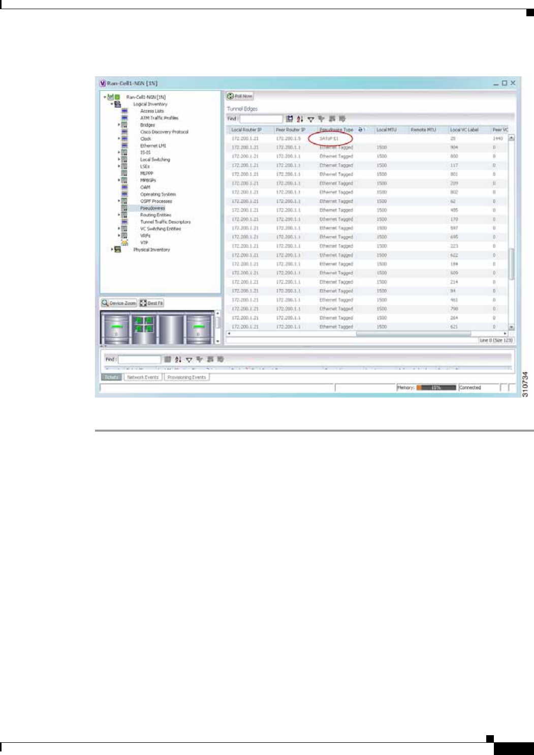
20-3
Cisco Prime Network 4.0 User Guide
OL-29343-01
Chapter 20 Monitoring MToP Services Viewing CESoPSN Pseudowire Type in Logical Inventory
Figure 20-1 SAToP Pseudowire Type in Logical Inventory
Step 4 To view the physical inventory for the port, click the hypertext port link.
Viewing CESoPSN Pseudowire Type in Logical Inventory
Circuit Emulation Services over PSN (CESoPSN) is a method for encapsulating structured (NxDS0)
TDM signals as pseudowires over packet-switching networks, complementary to SAToP. By emulating
NxDS0 circuits, CESoPSN:
• Saves PSN bandwidth.
• Supports DS0-level grooming and distributed cross-connect applications.
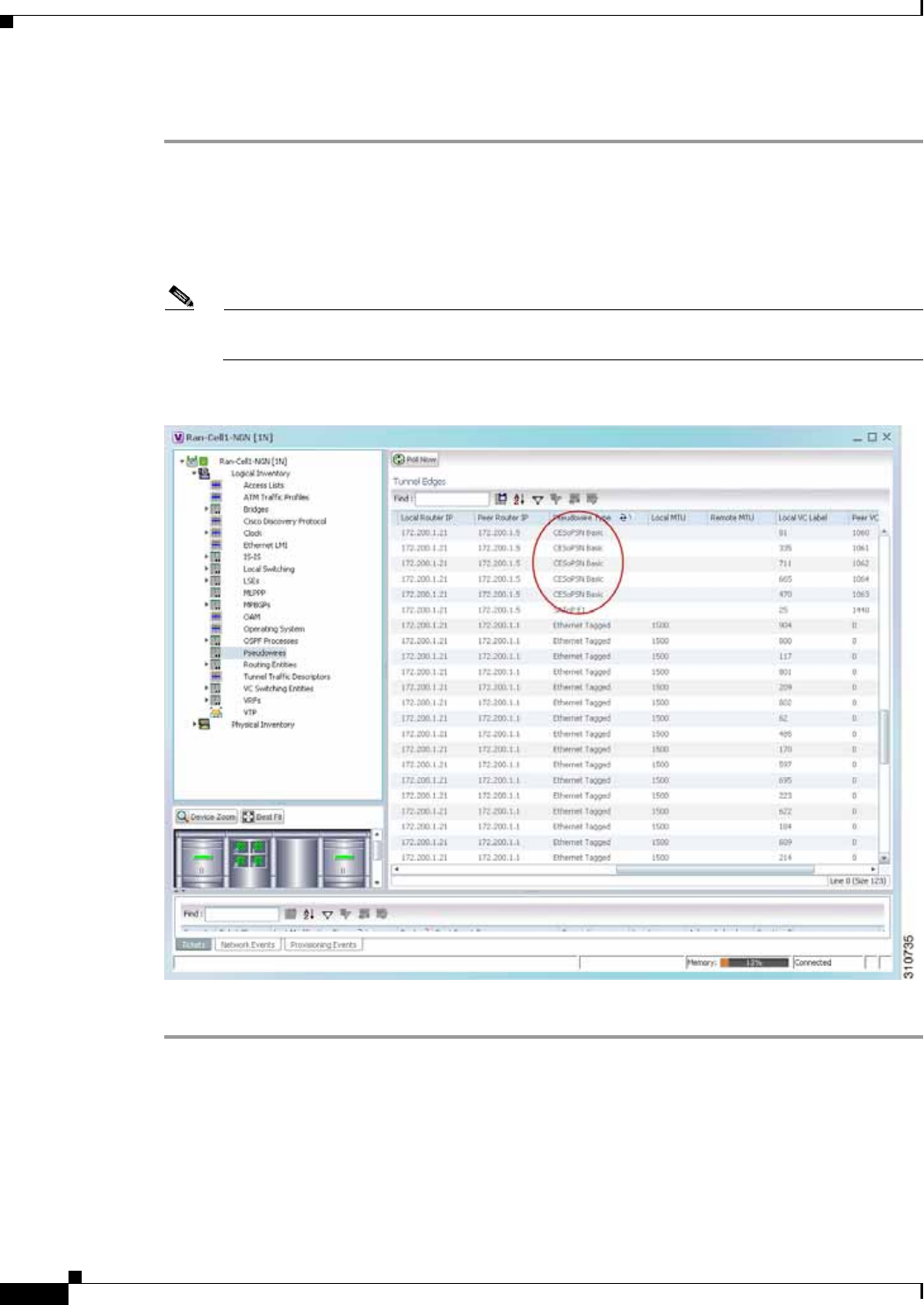
20-4
Cisco Prime Network 4.0 User Guide OL-29343-01
Chapter 20 Monitoring MToP Services
Viewing CESoPSN Pseudowire Type in Logical Inventory
To view TDM properties for Circuit Emulation (CEM) groups in Prime Network Vision:
Step 1 In Prime Network Vision, right-click the device on which CESoPSN is configured, then choose
Inventory.
Step 2 In the inventory window, choose Logical Inventory > Pseudowires.
Step 3 In the Tunnel Edges table, select the required entry and scroll horizontally until you see the Pseudowire
Type column. See Figure 20-2.
Note You can also view this information by right-clicking the entry in the table and choosing
Properties.
Figure 20-2 CESoPSN Pseudowire Type in Logical Inventory
Step 4 To view the physical inventory for the port, click the hypertext port link.
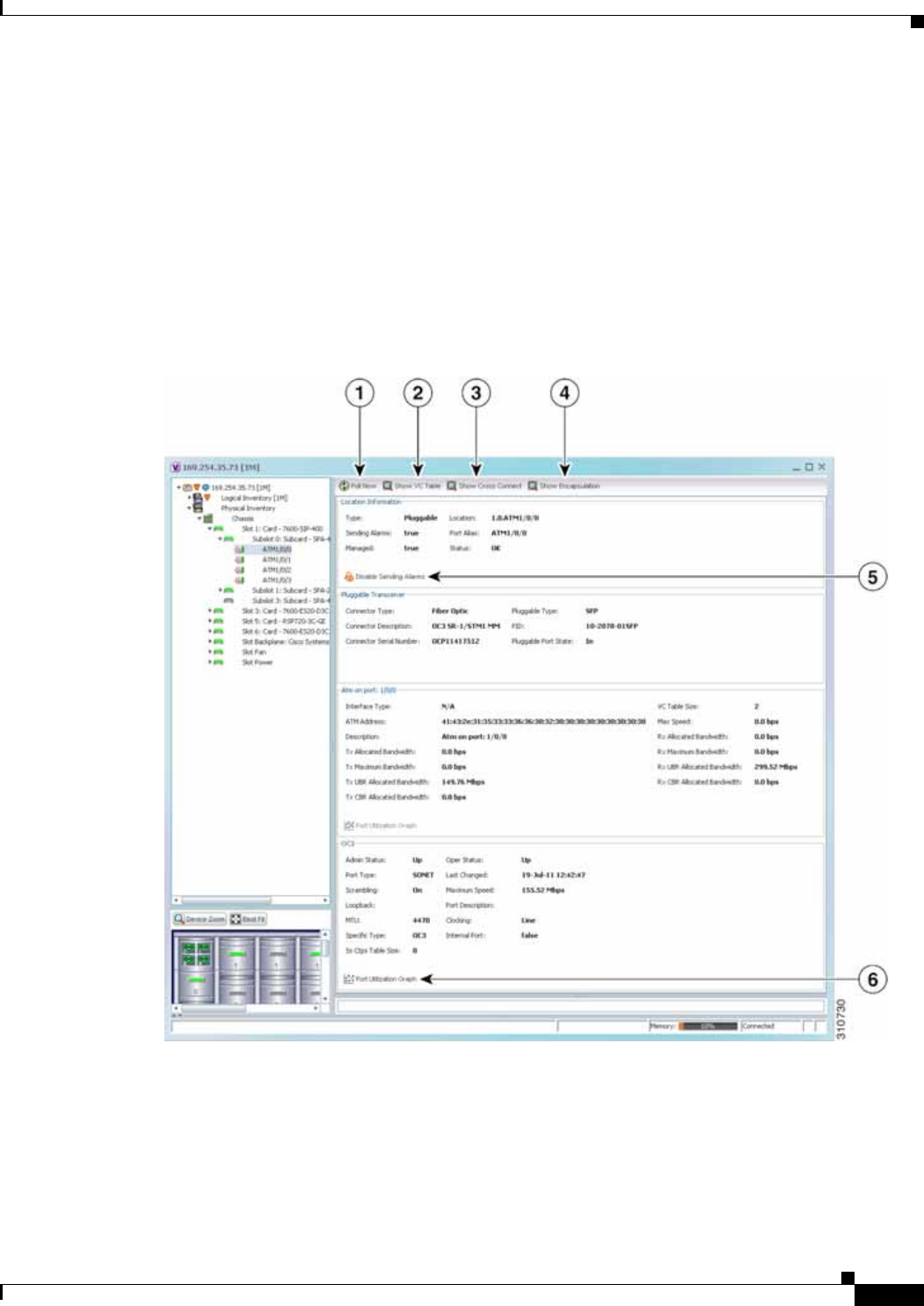
20-5
Cisco Prime Network 4.0 User Guide
OL-29343-01
Chapter 20 Monitoring MToP Services Viewing Virtual Connection Properties
Viewing Virtual Connection Properties
The following topics describe how to view properties related to virtual connections:
• Viewing ATM Virtual Connection Cross-Connects, page 20-6
• Viewing ATM VPI and VCI Properties, page 20-10
• Viewing Encapsulation Information, page 20-11
Buttons for viewing these properties are available at the top of the physical inventory window for the
selected interface, as shown in Figure 20-3.
Figure 20-3 ATM-Related Properties Available in Physical Inventory

20-6
Cisco Prime Network 4.0 User Guide OL-29343-01
Chapter 20 Monitoring MToP Services
Viewing Virtual Connection Properties
Viewing ATM Virtual Connection Cross-Connects
ATM networks are based on virtual connections over a high-bandwidth medium. By using
cross-connects to interconnect virtual path or virtual channel links, it is possible to build an end-to-end
virtual connection.
An ATM cross-connect can be mapped at either of the following levels:
• Virtual path—Cross-connecting two virtual paths maps one Virtual Path Identifier (VPI) on one port
to another VPI on the same port or a different port.
• Virtual channel—Cross-connecting at the virtual channel level maps a Virtual Channel Identifier
(VCI) of one virtual channel to another VCI on the same virtual path or a different virtual path.
Cross-connect tables translate the VPI and VCI connection identifiers in incoming ATM cells to the VPI
and VCI combinations in outgoing ATM cells. For information about viewing VPI and VCI properties,
see Viewing ATM VPI and VCI Properties, page 20-10.
1Poll Now button Polls the VNE for updated status.
2Show VC Table button Displays virtual circuit (VC) information for the selected port.. For more
information, see Viewing ATM VPI and VCI Properties, page 20-10.
3Show Cross Connect
button Displays cross-connect information for incoming and outgoing ports. For
more information, see Viewing ATM Virtual Connection
Cross-Connects, page 20-6.
4Show Encapsulation
button Displays encapsulation information for incoming and outgoing traffic for
the selected item. For more information, see Viewing Encapsulation
Information, page 20-11.
5Disable/Enable
Sending Alarms button Enables you to manage the alarms on a port. For more information, see
Working with Ports, page 3-23..
6Port Utilization Graph
button Displays the selected port traffic statistics: Rx/Tx Rate and Rx/Tx Rate
History. For more information, see Generating a Port Utilization Graph,
page 3-27.
—Show DLCI Table
button
(not displayed)
Displays data-link connection identifier (DCLI) information for the
selected port.

20-7
Cisco Prime Network 4.0 User Guide
OL-29343-01
Chapter 20 Monitoring MToP Services Viewing Virtual Connection Properties
To view ATM virtual connection cross-connects:
Step 1 In Prime Network Vision, right-click the required device, then choose Inventory.
Step 2 Open the VC Cross Connect table in either of the following ways:
• In the inventory window, choose Logical Inventory > VC Switching Entities > VC Switching
Entity. The Cross-Connect Table is displayed in the content pane as shown in Figure 20-4.
• In the inventory window:
a. Choose Physical Inventory > Chassis > Slot > Subslot > Port.
b. Click the Show Cross Connect button.
The VC Cross Connections window is displayed and contains the same information as the
Cross-Connect Table in logical inventory.
Step 3 Select an entry and scroll horizontally until you see the required information.
Figure 20-4 ATM Virtual Connection Cross-Connect Properties
Table 20-3 identifies the properties that are displayed for ATM VC cross-connects.

20-8
Cisco Prime Network 4.0 User Guide OL-29343-01
Chapter 20 Monitoring MToP Services
Viewing Virtual Connection Properties
Table 20-3 ATM Virtual Connection Cross-Connect Properties
Field Description
In Port Incoming port for the cross-connect.
In VC Incoming virtual connection for the cross-connect.
You can view additional details about the virtual connection in the following
ways:
• Click the hyperlinked entry to view the VC table.
• Right-click the entry, then choose Properties to view information about the
incoming and outgoing VCIs, VPI, service category, and traffic descriptors.
Out Port Outgoing port for the cross-connect.
Out VC Outgoing virtual connection for the cross-connect.
You can view additional details about the virtual connection in the following
ways:
• Click the hyperlinked entry to view the VC table.
• Right-click the entry, then choose Properties to view information about the
incoming and outgoing VCIs, VPI, service category, and traffic descriptors.
In VC Ingress
Traffic Descriptor ATM traffic parameters and service categories for the incoming traffic on the
incoming VC cross-connect.
For information on VC traffic descriptors, see Table 20-4.
In VC Egress
Traffic Descriptor ATM traffic parameters and service categories for the outgoing traffic on the
incoming VC cross-connect.
For information on VC traffic descriptors, see Table 20-4.
Out VC Egress
Traffic Descriptor ATM traffic parameters and service categories for the outgoing traffic on the
outgoing VC cross-connect.
For information on VC traffic descriptors, see Table 20-4.
Out VC Ingress
Traffic Descriptor ATM traffic parameters and service categories for the incoming traffic on the
outgoing VC cross-connect.
For information on VC traffic descriptors, see Table 20-4.

20-9
Cisco Prime Network 4.0 User Guide
OL-29343-01
Chapter 20 Monitoring MToP Services Viewing Virtual Connection Properties
Table 20-4 Virtual Connection Traffic Descriptors
Value Description
ABR Available bit rate (ABR) supports nonreal-time applications that tolerate high
cell delay, and can adapt cell rates according to changing network resource
availability to prevent cell loss.
CBR Constant bit rate (CBR) supports real-time applications that request a static
amount of bandwidth that is continuously available for the duration of the
connection.
CDVT Cell Delay Variation Tolerance (CDVT) specifies an acceptable deviation in
cell times for a PVC that is transmitting above the PCR. For a given cell
interarrival time expected by the ATM switch, CDVT allows for some variance
in the transmission rate.
CLP Cell loss priority (CLP) indicates the likelihood of a cell being dropped to ease
network congestion.
MBS Maximum Burst Size (MBS) specifies the number of cells that the edge device
can transmit up to the PCR for a limited period of time without penalty for
violation of the traffic contract.
MCR Minimum Cell Rate (MCR) specifies the cell rate (cells per second) at which
the edge device is always allowed to transmit.
PCR Peak Cell Rate (PCR) specifies the cell rate (cells per second) that the edge
device cannot exceed.
PDR CLP0+1: 1536 Packet delivery ratio (PDR) for all cells (both CLP1 and CLP0 cells) on the
circuit.
SCR Sustainable Cell Rate (SCR) specifies the upper boundary for the average rate
at which the edge device can transmit cells without loss.
UBR Unspecified Bit Rate (UBR) supports nonreal-time applications that tolerate
both high cell delay and cell loss on the network.
UBR+ Unspecified bit rate plus (UBR+) supports nonreal-time applications that
tolerate both high cell delay and cell loss on the network, but request a
minimum guaranteed cell rate.
nrt-VBR Nonreal-time variable bit rate (nrt-VBR) supports nonreal-time applications
with bursty transmission characteristics that tolerate high cell delay, but require
low cell loss.
rt-VBR rt-VBR—Real-time variable bit rate (rt-VBR) supports real-time applications
that have bursty transmission characteristics.
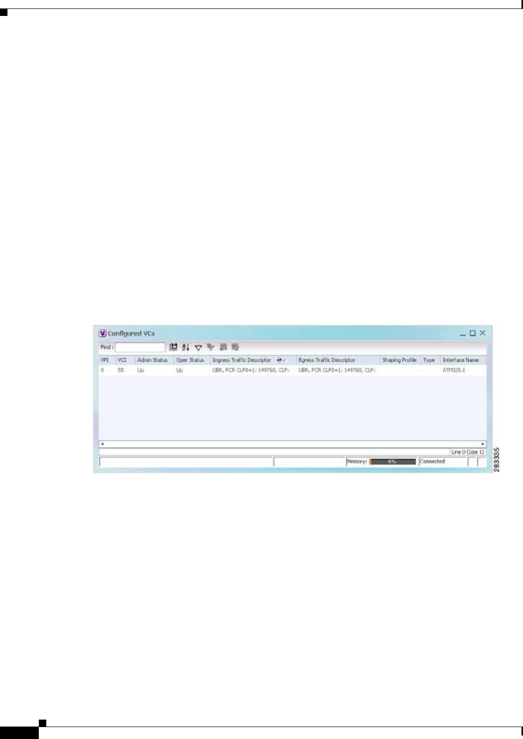
20-10
Cisco Prime Network 4.0 User Guide OL-29343-01
Chapter 20 Monitoring MToP Services
Viewing Virtual Connection Properties
Viewing ATM VPI and VCI Properties
If you know the interface or link configured for virtual connection cross-connects, you can view ATM
VPI and VCI properties from the physical inventory window or from the link properties window.
To view ATM VPI and VCI properties, open the VC Table window in either of the following ways:
• To open the VC Table window from physical inventory:
a. In the map view, double-click the element configured for virtual connection cross-connects.
b. In the inventory window, choose Physical Inventory > Chassis > Slot > Subslot > Port.
c. Click Show VC Table.
• To view the VC Table window from the link properties window:
a. In the map or links view, right-click the required ATM link and choose Properties.
b. In the link properties window, click Calculate VCs.
c. After the screen refreshes, click either Show Configured or Show Misconfigured to view the
virtual connection cross-connects.
The VC Table window is displayed, as shown in Figure 20-5.
Figure 20-5 VC Table
Table 20-5 describes the information displayed in the VC Table window.

20-11
Cisco Prime Network 4.0 User Guide
OL-29343-01
Chapter 20 Monitoring MToP Services Viewing Virtual Connection Properties
Viewing Encapsulation Information
To view virtual connection encapsulation information:
Step 1 In Prime Network Vision, double-click the element configured for virtual connection encapsulation.
Step 2 In the inventory window, choose Physical Inventory > Chassis > Slot > Subslot > Port.
Step 3 Click the Show Encapsulation button.
The VC Encapsulation window is displayed as shown in Figure 20-6.
Table 20-5 VC Table Properties
Field Description
VPI Virtual Path Identifier for the selected port.
VCI Virtual Channel Identifier for the selected port.
Admin Status Administrative state of the connection: Up, Down, or Unknown.
Oper Status Operational state of the connection: Up, Down, or Unknown.
Ingress Traffic Descriptor Traffic parameters and service categories for the incoming traffic. For
information on VC traffic descriptors, see Table 20-4.
Egress Traffic Descriptor Traffic parameters and service categories for the outgoing traffic. For
information on VC traffic descriptors, see Table 20-4.
Shaping Profile Traffic shape profile used for the virtual connection.
Type ATM traffic descriptor type for the virtual connection.
Interface Name Interface name, such as ATM1/1/16.
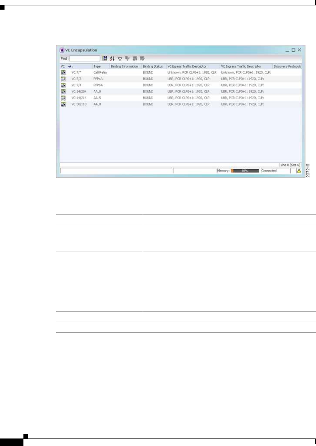
20-12
Cisco Prime Network 4.0 User Guide OL-29343-01
Chapter 20 Monitoring MToP Services
Viewing Virtual Connection Properties
Figure 20-6 VC Encapsulation Properties
Table 20-6 describes the information displayed in the VC Encapsulation window.
Table 20-6 VC Encapsulation Properties
Field Description
VC Virtual connection identifier, such as VC:7/4.
Type Type of encapsulation, such as Point-to-Point Protocol (PPP) over
ATM (PPPoA) or ATM adaption layer Type 5 (AAL5).
Binding Information Information tied to the virtual connection, such as a username.
Binding Status Binding state: Bound or Unbound.
VC Egress Traffic Descriptor Traffic parameters and service categories for the outgoing traffic.
For information on VC traffic descriptors, see Table 20-4.
VC Ingress Traffic Descriptor Traffic parameters and service categories for the incoming traffic.
For information on VC traffic descriptors, see Table 20-4.
Discovery Protocols Discovery protocol used for the VC.
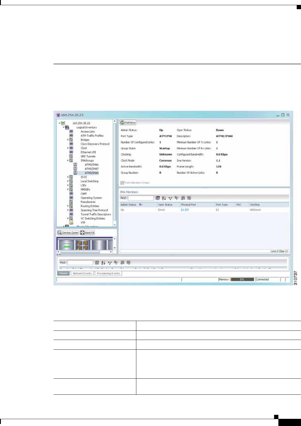
20-13
Cisco Prime Network 4.0 User Guide
OL-29343-01
Chapter 20 Monitoring MToP Services Viewing IMA Group Properties
Viewing IMA Group Properties
To view IMA group properties:
Step 1 In Prime Network Vision, double-click the required device.
Step 2 In the inventory window, choose Logical Inventory > IMA Groups > group. IMA group properties and
the IMA Members table are displayed in the content pane as shown in Figure 20-7.
Figure 20-7 IMA Group Properties
Table 20-7 describes the information displayed for the IMA group.
Table 20-7 IMA Group Properties
Field Description
Active Bandwidth Active bandwidth of the IMA group.
Admin Status Administrative status of the IMA group.
Clock Mode Clock mode the IMA group is using:
• Common—Common transmit clocking (CTC).
• Independent—Independent transmit clocking (ITC).
Configured Bandwidth Total bandwidth of the IMA group, which is the sum of all
individual links in the group.

20-14
Cisco Prime Network 4.0 User Guide OL-29343-01
Chapter 20 Monitoring MToP Services
Viewing IMA Group Properties
Description IMA group interface name.
Frame Length Length of the IMA group transmit frames, in the number of cells:
32, 64, 128, or 256.
A small frame length causes more overhead but loses less data if a
problem occurs. We recommend a frame length of 128 cells.
Group Number IMA group number.
Group State IMA group status, in the order of usual appearance:
• Startup—The near end is waiting to receive indication that the
far end is in Startup. The IMA group moves to the Startup-Ack
state when it can communicate with the far end and has
recorded IMA identifier, group symmetry, and other IMA group
parameters.
• Startup ACK—Both sides of the link are enabled.
• Config Aborted—The far end has unacceptable configuration
parameters, such as an unsupported IMA frame size, an
incompatible group symmetry, or an unsupported IMA version.
• Insufficient Links—The near end has accepted the far end
group parameters, but the far end does not have sufficient links
to move into the Operational state.
• Operational—The group is not inhibited and has sufficient links
in both directions. The IMA interface can receive ATM layer
cells and pass them from the IMA sublayer to the ATM layer.
• Blocked—The group is blocked, even though sufficient links
are active in both directions.
IMA Version IMA version configured, either 1.0 or 1.1.
Minimum Number of Rx Links Minimum number of Rx links needed for the IMA group to be
operational.
Minimum Number of Tx Links Minimum number of Tx links needed for the IMA group to be
operational.
Number of Active Links Number of DS1 (E1 or T1) links that are active in the group.
Number of Configured Links Number of DS1 (E1 or T1) links that are configured in the IMA
group.
Oper Status Operational state of the IMA group interface:
• Dormant—The interface is dormant.
• Down—The interface is down.
• Not Present—An interface component is missing.
• Testing—The interface is in test mode.
• Unknown—The interface has an unknown operational status.
• Up—The interface is up.
Port Type Type of port, such as ATM IMA.
Table 20-7 IMA Group Properties (continued)
Field Description

20-15
Cisco Prime Network 4.0 User Guide
OL-29343-01
Chapter 20 Monitoring MToP Services Viewing IMA Group Properties
Table 20-8 describes the information displayed in the IMA Members table.
Step 3 In the IMA Members table, click a hyperlinked port entry to view the port properties in physical
inventory. See Figure 20-8.
The information that is displayed for the port in physical inventory depends on the type of connection,
such as SONET or ATM.
Table 20-8 IMA Members Table
Column Description
Admin Status Administrative status of the IMA member.
Channelization Channelization that occurs through the path, such as STS1-> VTG-> VT15.
Information is displayed in this field only if the T1 or E1 path was
channelized. If the line was not channelized, this field is not displayed. For
example, if the IMA group is configured on a T1 or E1 card, this field is not
displayed.
Clocking Source of the clocking mechanism: Internal or Line.
Description Type of channelization, such as Synchronous Transport Signal 1 (STS-1) or
Synchronous Transport Module level 1 (STM-1).
Oper Status Operational state of the IMA member:
Physical Port Hyperlinked entry to the port in physical inventory.
Port Type Type of port, such as E1 or T1.
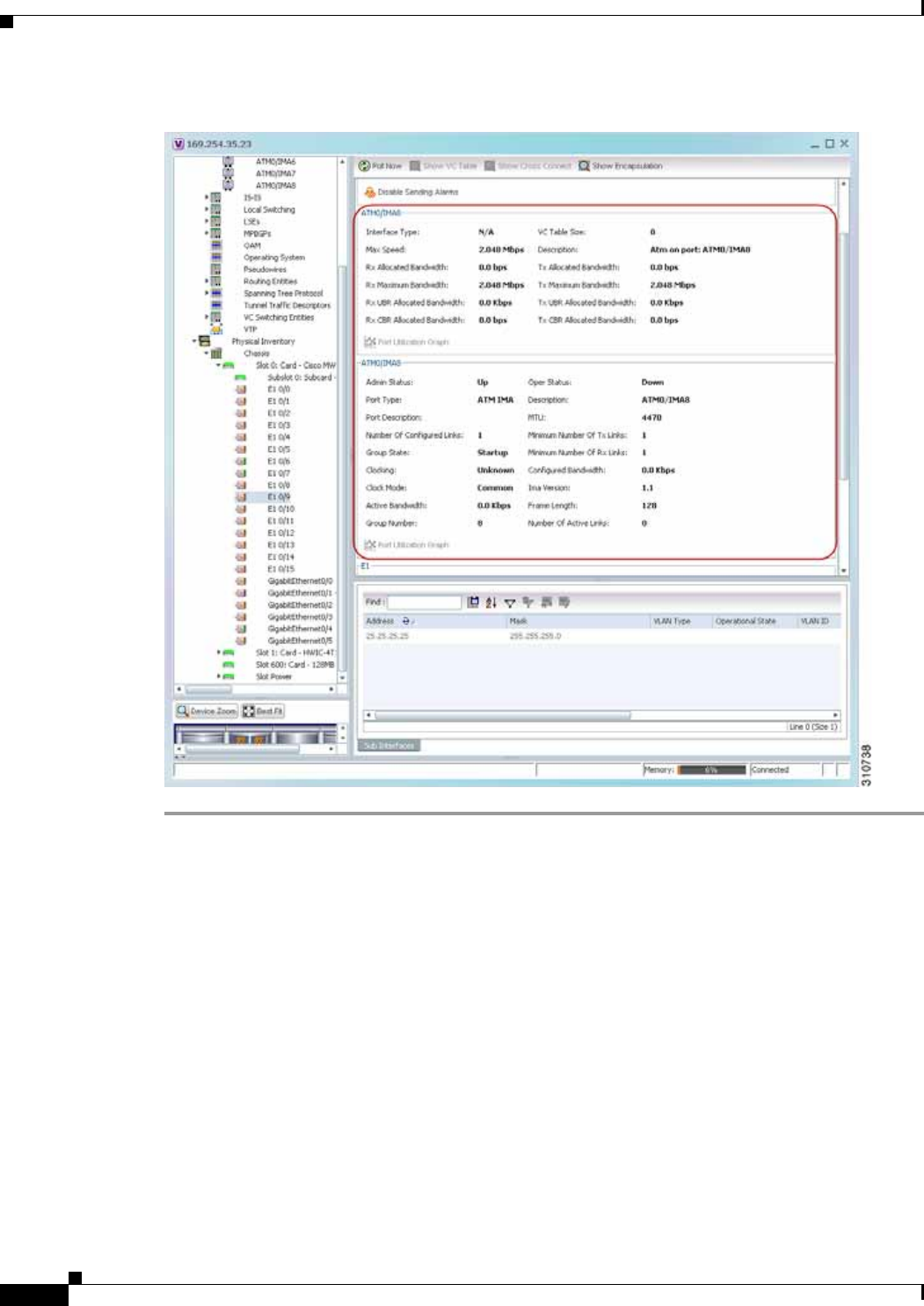
20-16
Cisco Prime Network 4.0 User Guide OL-29343-01
Chapter 20 Monitoring MToP Services
Viewing TDM Properties
Figure 20-8 ATM IMA Port in Physical Inventory
Viewing TDM Properties
TDM is a mechanism for combining two or more slower-speed data streams into a single high-speed
communication channel. In this model, data from multiple sources is divided into segments that are
transmitted in a defined sequence. Each incoming data stream is allocated a timeslot of a fixed length,
and the data from each stream is transmitted in turn. For example, data from data stream 1 is transmitted
during timeslot 1, data from data stream 2 is transmitted during timeslot 2, and so on. After each
incoming stream has transmitted data, the cycle begins again with data stream 1. The transmission order
is maintained so that the input streams can be reassembled at the destination.

20-17
Cisco Prime Network 4.0 User Guide
OL-29343-01
Chapter 20 Monitoring MToP Services Viewing Channelization Properties
MToP encapsulates TDM streams for delivery over packet-switching networks (PSNs) using the
following methods:
• SAToP—A method for encapsulating TDM bit-streams (T1, E1, T3, or E3) as pseudowires over
PSNs.
• CESoPSN—A method for encapsulating structured (NxDS0) TDM signals as pseudowires over
PSNs.
For T1 or E1 entries, the TDM properties presented in Table 20-9 are displayed in physical inventory in
addition to the existing T1 or E1 properties.
Viewing Channelization Properties
Prime Network Vision supports the channelization of SONET/SDH and T3 lines. When a line is
channelized, it is logically divided into smaller bandwidth channels called paths. These paths (referred
to as high order paths or HOPs) can, in turn, contain low order paths, or LOPs. The sum of the bandwidth
on all paths cannot exceed the line bandwidth.
For SONET show and configuration commands, see Configuring SONET, page 20-53.
The following topics describe how to view channelization properties for SONET/SDH and T3 lines:
• Viewing SONET/SDH Channelization Properties, page 20-18
• Viewing T3 DS1 and DS3 Channelization Properties, page 20-21
Table 20-9 TDM-Specific Properties for DS1 (T1 or E1) in Physical Interfaces
Field Description
International Bit Whether or not the international bit is used by the controller:
• 0—The international bit is not used.
• 1—The international bit is used.
This property applies only to E1.
National Bits Whether or not the national reserve bits (sa4, sa5, sa6, sa7, and sa8) are used
by the controller:
• 0—The national reserve bits are not used.
• 1—The national reserve bits are used.
This property applies only to E1.
Line Code Line encoding method for the DS1 link:
• For E1, the options are Alternate Mark Inversion (AMI) and
high-density bipolar of order 3 (HDB3).
• For T1, the options are AMI and bipolar with 8 zero substitution (B8ZS).
Cable Length For T1 ports in short-haul mode, the length of the cable in feet.
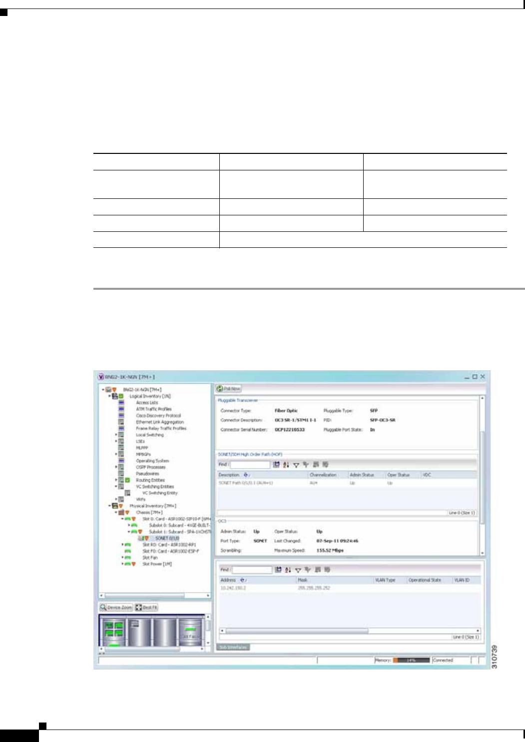
20-18
Cisco Prime Network 4.0 User Guide OL-29343-01
Chapter 20 Monitoring MToP Services
Viewing Channelization Properties
Viewing SONET/SDH Channelization Properties
SONET and SDH use the same concepts for channelization, but the terminology differs. Table 20-10
describes the equivalent terms for SONET and SDH channelization. The information displayed in Prime
Network Vision reflects whether SONET or SDH is configured on the interface.
To view SONET/SDH channelization properties:
Step 1 In Prime Network Vision, right-click the required device, then choose Inventory.
Step 2 Choose Physical Inventory > Chassis > slot > subslot > SONET/SDH-interface. The properties for
SONET/SDH and OC-3 are displayed in the content pane. See Figure 20-9.
Figure 20-9 SONET/SDH Interface in Physical Inventory
Table 20-10 SONET and SDH Channelization Terminology
Concept SONET Term SDH Term
Frame Synchronous Transport Signal
level N (STS-N) Synchronous Transport Module
level N (STM-N)
HOP channel STS-1 Administrative Unit (AU-n)
Lower-order channels Virtual Tributary (VT) Tributary Unit Group (TUG)
LOP payloads DS1, DS3, or E1

20-19
Cisco Prime Network 4.0 User Guide
OL-29343-01
Chapter 20 Monitoring MToP Services Viewing Channelization Properties
Table 20-11 describes the information that is displayed for SONET/SDH and OC3 in the content pane.
Step 3 To view additional information about a channelized path, double-click the required entry in the
Description column. The SONET/SDH High Order Path Properties window is displayed as shown in
Figure 20-10.
Table 20-11 SONET/SDH and OC3 Properties
Field Description
SONET/SDH High Order Path (HOP) Area
Description SONET/SDH path description including the interface and high order
path. Double-click an entry to view additional details about the path.
Channelization Type of channelization, such as STS-1 or STM-1.
Admin Status Administrative status of the HOP.
Oper Status Operational status of the HOP.
OC3 Area
Admin Status Administrative status of the OC-3 line.
Oper Status Operational status of the OC-3 line.
Port Type Type of port.
Last Changed Date and time of the last status change of the line.
Scrambling Any scrambling that has been applied to the SONET payload.
Maximum Speed Maximum bandwidth for the line.
Loopback Loopback setting configured on the line.
Port Description Description of the port defined by the user.
Clocking Clocking configured on the line.
Specific Type Specific type of line; in this case, OC3.
Internal Port Whether or not the line includes an internal port: True or False.
Ss Ctps Table Size Size of the SONET/SDH Connection Termination Point (CTP) table.
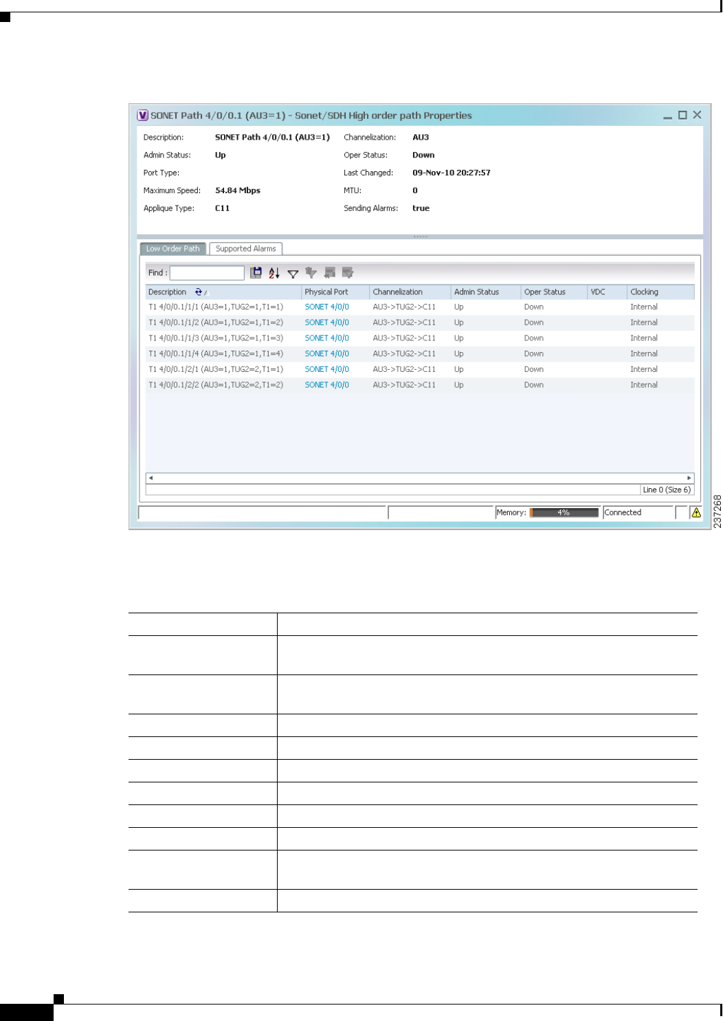
20-20
Cisco Prime Network 4.0 User Guide OL-29343-01
Chapter 20 Monitoring MToP Services
Viewing Channelization Properties
Figure 20-10 SONET/SDH High Order Path Properties Window
Table 20-12 describes the information displayed in SONET/SDH High Order Path Properties window.
Table 20-12 SONET/SDH High Order Path Properties
Field Description
Description SONET/SDH path description including the interface and high order
path. Double-click an entry to view additional details about the path.
Channelization Type of channelization, such as Synchronous Transport Signal 1
(STS-1) or Synchronous Transport Module level 1 (STM-1).
Admin Status Administrative status of the HOP.
Oper Status Operational status of the HOP.
Port Type Type of port.
Last Changed Date and time of the last status change of the path.
Maximum Speed Maximum bandwidth for the line.
MTU MTU for the path.
Applique Type Sub-STS-1 facility applied to this path. In this example, the facility
applied is Virtual Tributary 1.5 (VT1.5).
Sending Alarms Whether or not the path is sending alarms: True or False.

20-21
Cisco Prime Network 4.0 User Guide
OL-29343-01
Chapter 20 Monitoring MToP Services Viewing Channelization Properties
Viewing T3 DS1 and DS3 Channelization Properties
To view T3 DS1 and DS3 channelization properties:
Step 1 In Prime Network Vision, right-click the required device, then choose Inventory.
Step 2 Choose Physical Inventory > Chassis > slot > subslot > T3-interface.
Figure 20-11 shows DS1 channelization properties for T3 in physical inventory.
Low Order Path Tab
Description Description of the low order path down to the T1 level, including the
channel types (such as STS-1, VTG, or VT) and channel allocated.
Physical Port Hyperlinked entry to the port in physical inventory.
Channelization Channelization that occurs through the path, such as
STS1-> VTG-> VT15.
Admin Status Administrative status of the path.
Oper Status Operational status of the path.
Clocking Source of the clocking mechanism: Internal or Line.
Supported Alarms Tab
Name Supported alarm.
Enable Whether the alarm is enabled or disabled.
Table 20-12 SONET/SDH High Order Path Properties (continued)
Field Description
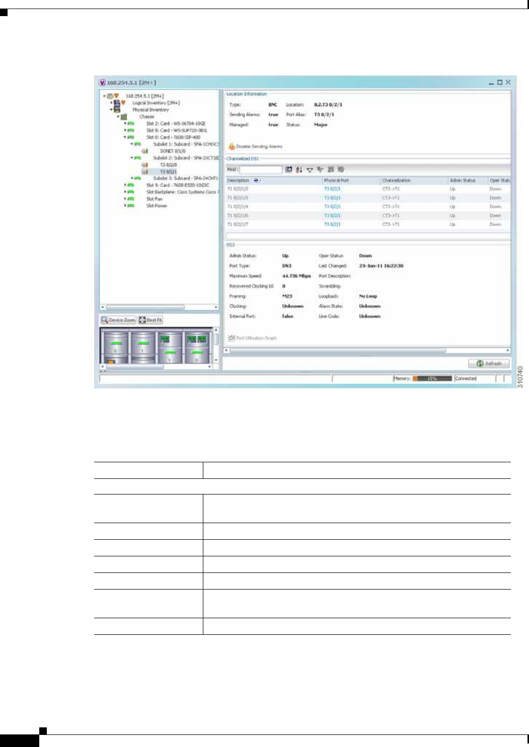
20-22
Cisco Prime Network 4.0 User Guide OL-29343-01
Chapter 20 Monitoring MToP Services
Viewing Channelization Properties
Figure 20-11 T3 DS1 Channelization Properties in Physical Inventory
Table 20-13 describes the information that is displayed for Channelized DS1 and DS3 in the content
pane.
Table 20-13 Channelized DS1 and DS3 Properties
Field Description
Channelized DS1 Table
Description Path description including the physical interface and the channel
number. Double-click an entry to view additional details about the path.
Physical Port Physical port for the channelized line.
Channelization Type of channelization, such as channelized T3 (CT3) to T1.
Admin Status Administrative status of the channelized line.
Oper Status Operational status of the channelized line.
VDC For devices with multiple virtual contexts, the context associated with
the channelized line.
Clocking Clocking configured on the line: Internal or Line.

20-23
Cisco Prime Network 4.0 User Guide
OL-29343-01
Chapter 20 Monitoring MToP Services Viewing Channelization Properties
Step 3 To view additional information about a DS1channelized path, double-click the required entry in the
Channelized DS1 table. Figure 20-12 shows the information that is displayed in the Channelized DS1
PDH Properties window.
DS3 Area
Admin Status Administrative status of the DS3 line.
Oper Status Operational status of the DS3 line.
Port Type Type of port.
Last Changed Date and time of the last status change of the line.
Maximum Speed Maximum bandwidth for the line.
Port Description Description of the port configured on the interface.
Recovered Clocking ID Recovered clock identifier, if known.
Scrambling Any scrambling that has been applied to the SONET payload.
Framing Type of framing applied to the line.
Loopback Loopback setting configured on the line.
Clocking Clocking configured on the line: Internal or Line.
Alarm State Alarm state of the DS3 line:
• Clear—The alarm state is clear.
• AIS—Alarm Indication Signal (AIS).
• LOS—Loss of signal (LOS) alarm.
• AIS_LOS—AIS loss of signal alarm.
• LOF—Loss of frame (LOF) alarm.
• AIS_LOF—AIS loss of frame alarm.
• LOS_LOF—Loss of signal and loss of frame alarm.
• AIS_LOS_LOF—AIS loss of signal and loss of frame alarm.
• Unknown—Unknown alarm.
Internal Port Whether or not the line includes an internal port: True or False.
Line Code Line coding applied to the line.
Table 20-13 Channelized DS1 and DS3 Properties (continued)
Field Description
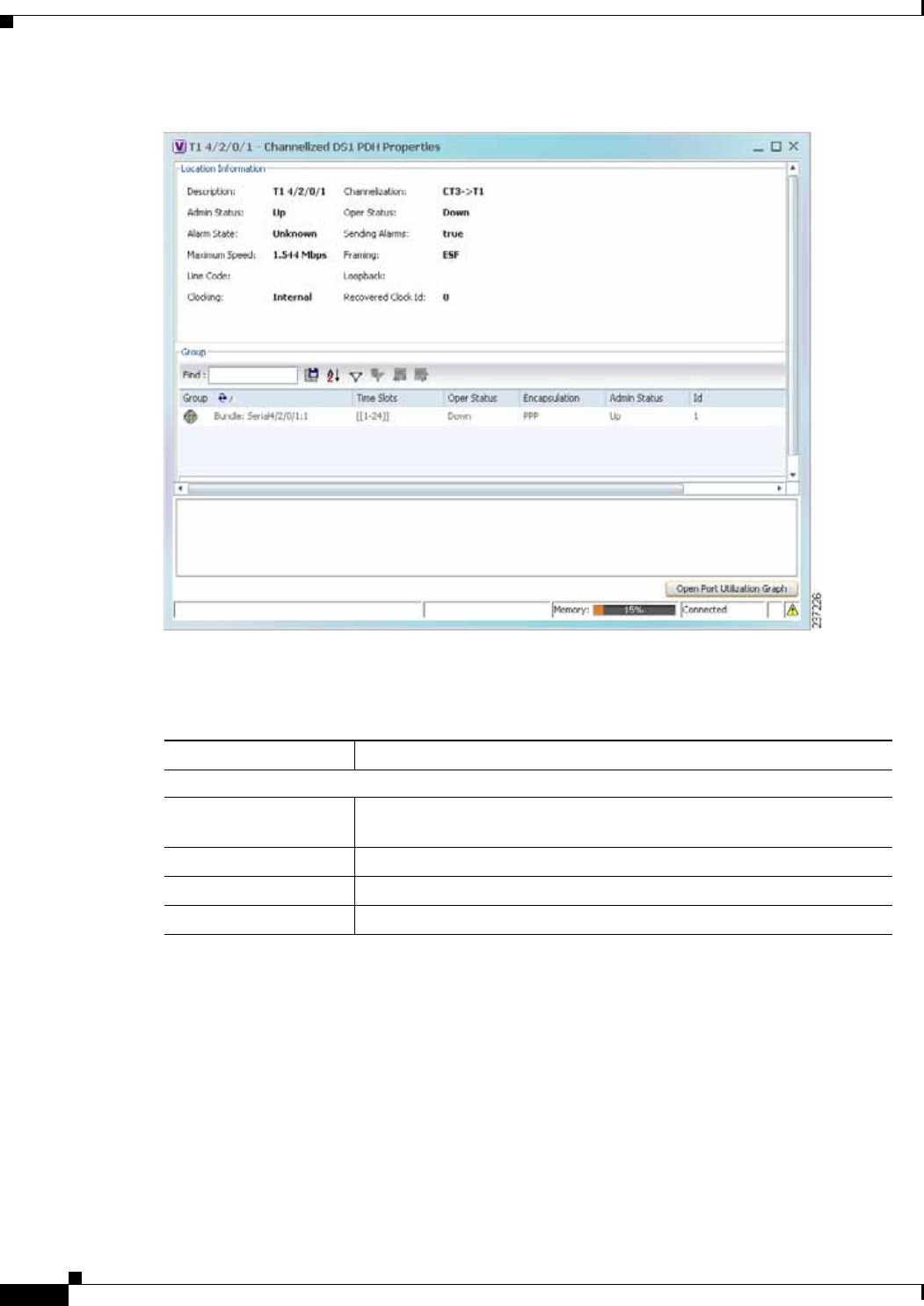
20-24
Cisco Prime Network 4.0 User Guide OL-29343-01
Chapter 20 Monitoring MToP Services
Viewing Channelization Properties
Figure 20-12 Channelized DS1 PDH Properties Window
Table 20-14 describes the information that is displayed in the Channelized DS1 PDH Properties window.
Table 20-14 Channelized DS1 PDH Properties Window
Field Description
Location Area
Description Path description including the physical interface and the channel
number.
Channelization Type of channelization used on the line, such as CT3-> T1.
Admin Status Administrative status of the channelized line.
Oper Status Operational status of the channelized line.

20-25
Cisco Prime Network 4.0 User Guide
OL-29343-01
Chapter 20 Monitoring MToP Services Viewing Channelization Properties
Alarm State Alarm state of the DS1 line:
• Clear—The alarm state is clear.
• AIS—Alarm Indication Signal (AIS).
• LOS—Loss of signal (LOS) alarm.
• AIS_LOS—AIS loss of signal alarm.
• LOF—Loss of frame (LOF) alarm.
• AIS_LOF—AIS loss of frame alarm.
• LOS_LOF—Loss of signal and loss of frame alarm.
• AIS_LOS_LOF—AIS loss of signal and loss of frame alarm.
• Unknown—Unknown alarm.
Sending Alarms Whether or not the line is sending alarms: True or False.
Maximum Speed Maximum bandwidth for the line.
Framing Type of framing applied to the line.
Line Code Line coding applied to the line.
Loopback Loopback setting configured on the line.
Clocking Clocking configured on the line: Internal or Line.
Recovered Clock ID Recovered clock identifier, if known.
Group Table
This table appears only if a DS0 bundle is configured on a channelized DS1 line. The properties
that are displayed pertain to the DS0 bundle.
Group Name of the DS0 bundle.
Time Slots Range of timeslots (DS0 channels) allotted to the group.
Oper Status Operational status of the group.
Encapsulation Type of encapsulation used, such as High-Level Data Link Control
(HDLC).
Admin Status Administrative status of the group.
ID DS0 bundle identifier.
Table 20-14 Channelized DS1 PDH Properties Window (continued)
Field Description
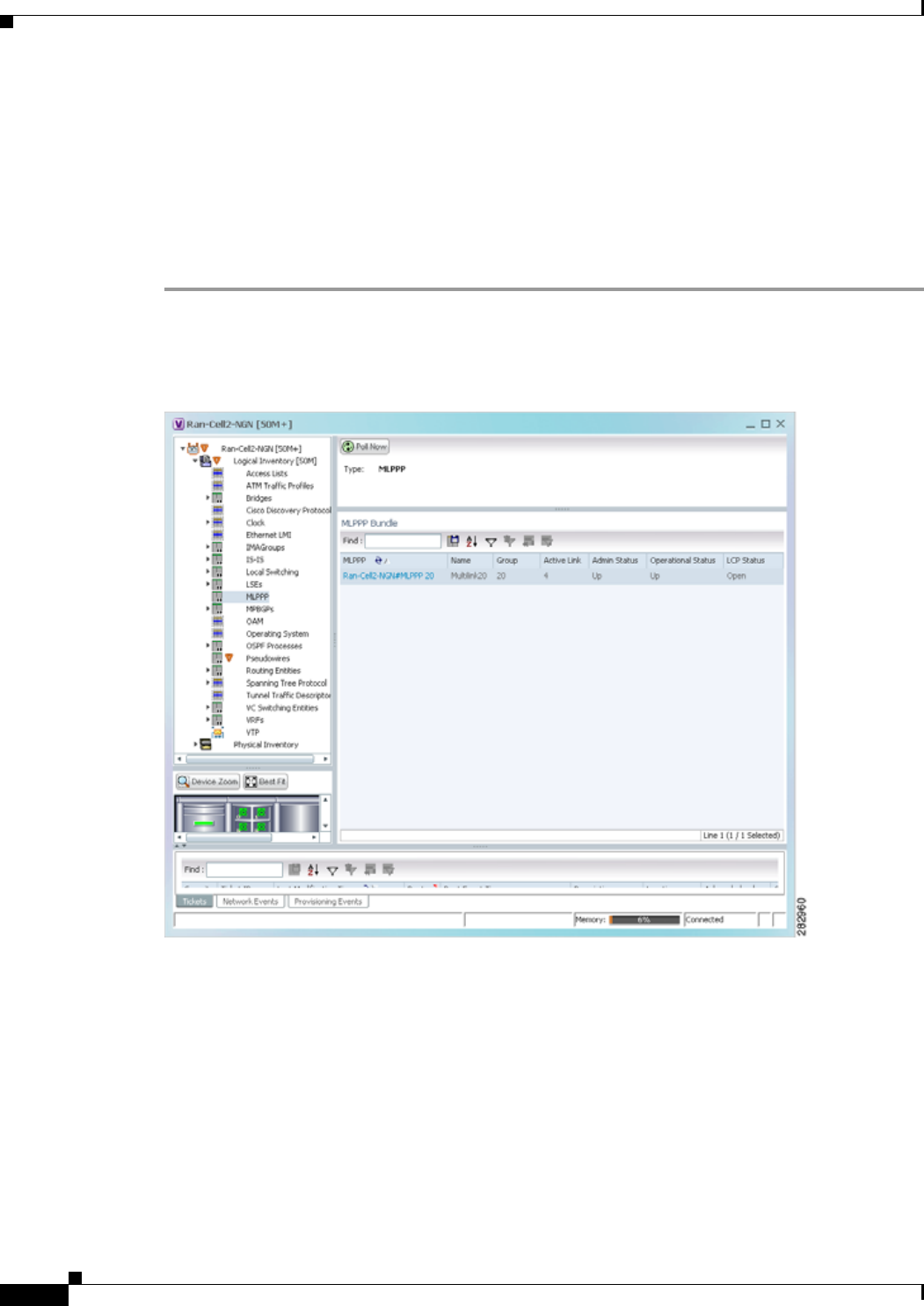
20-26
Cisco Prime Network 4.0 User Guide OL-29343-01
Chapter 20 Monitoring MToP Services
Viewing MLPPP Properties
Viewing MLPPP Properties
Multilink PPP (MLPPP) is a protocol that connects multiple links between two systems as needed to
provide bandwidth when needed. MLPPP packets are fragmented, and the fragments are sent at the same
time over multiple point-to-point links to the same remote address. MLPPP provides bandwidth on
demand and reduces transmission latency across WAN links.
To view MLPPP properties:
Step 1 In Prime Network Vision, right-click the required device, then choose Inventory.
Step 2 In the inventory window, choose Logical Inventory > MLPPP. See Figure 20-13.
Figure 20-13 MLPPP Properties in Logical Inventory
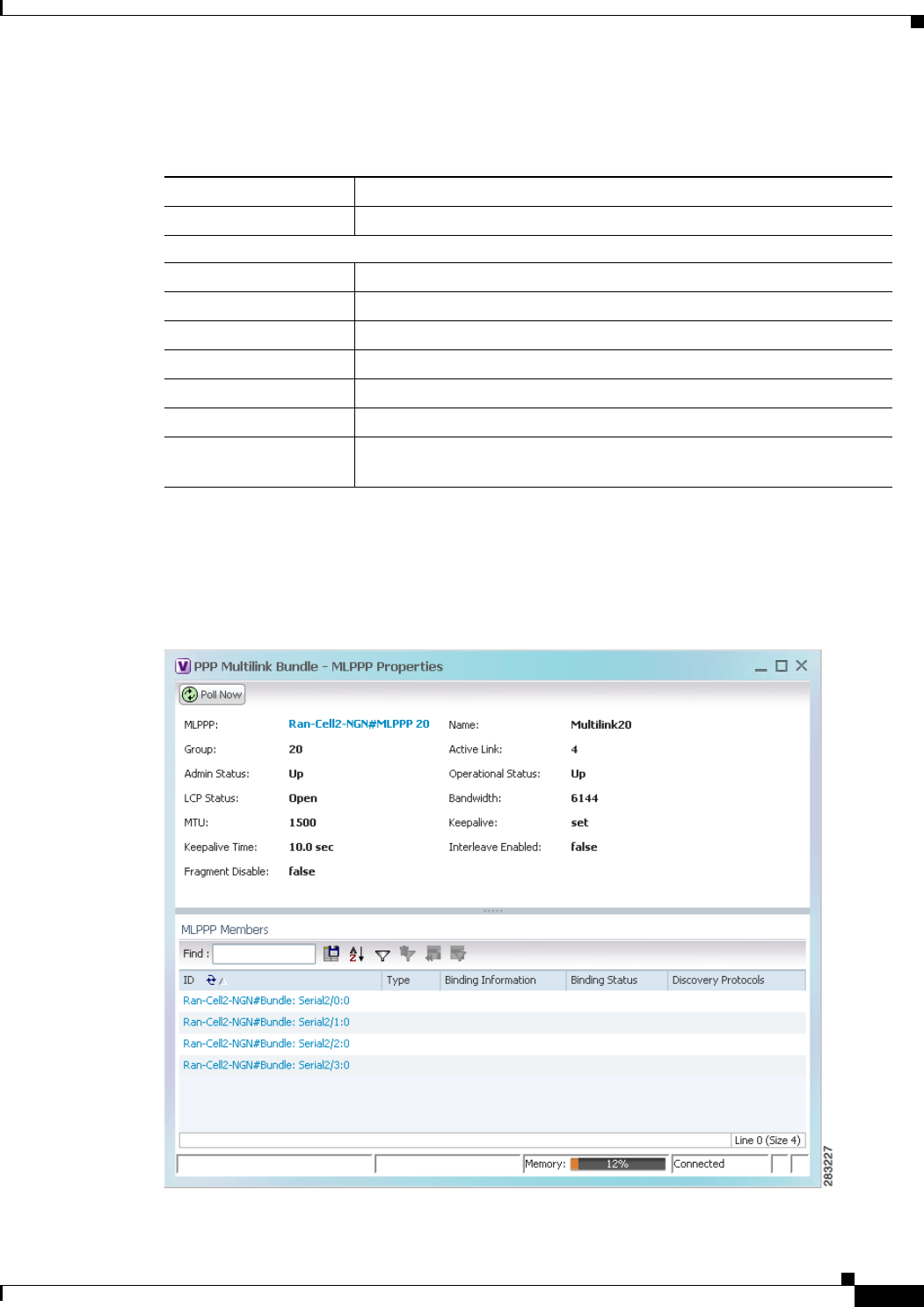
20-27
Cisco Prime Network 4.0 User Guide
OL-29343-01
Chapter 20 Monitoring MToP Services Viewing MLPPP Properties
Table 20-15 describes the information that is displayed for MLPPP.
Step 3 To view properties for individual MLPPP bundles, double-click the hyperlinked entry in the MLPPP
Bundle table.
The MLPPP Properties window is displayed as shown in Figure 20-14.
Figure 20-14 MLPPP Bundle Properties Window
Table 20-15 MLPPP Properties
Field Description
Type Type of properties; in this case, MLPPP.
MLPPP Bundle Table
MLPPP MLPPP bundle name, hyperlinked to the MLPPP Properties window.
Name MLPPP interface name.
Group MLPPP group to which the bundle belongs.
Active Link Number of active interfaces participating in MLPPP.
Admin Status Administrative status of the MLPPP bundle: Up or Down.
Operational Status Administrative status of the MLPPP bundle: Up or Down.
LCP Status Link Control Protocol (LCP) status of the MLPPP bundle: Closed,
Open, Started, or Unknown.

20-28
Cisco Prime Network 4.0 User Guide OL-29343-01
Chapter 20 Monitoring MToP Services
Viewing MLPPP Properties
Table 20-16 describes the information that is displayed in the MLPPP Properties window.
Table 20-16 MLPPP Bundle and Member Properties
Field Description
MLPPP MLPPP bundle name, hyperlinked to MLPPP in logical inventory.
Name MLPPP interface name.
Group Group to which the MLPPP bundle belongs.
Active Link Number of active interfaces participating in MLPPP.
Admin Status Administrative status of the MLPPP bundle: Up or Down.
Operational Status Operational status of the MLPPP bundle: Up or Down.
LCP Status Link Control Protocol (LCP) status of the MLPPP bundle: Closed,
Open, Started, or Unknown.
Minimum Configured
Link Minimum number of configured links for an MLPPP bundle.
Maximum Configured
Link Maximum number of configured links for an MLPPP bundle.
Bandwidth Bandwidth allocated to the MLPPP bundle.
MTU Size of the Maximum Transmission Unit (MTU), from 1 to 2147483647
bytes.
Keepalive Status of the keepalive function: Set, Not Set, or Unknown.
Keepalive Time If keepalive is enabled, the amount of time, in seconds, to wait before
sending a keepalive message.
Interleave Enabled Whether or not interleaving of small fragments is enabled.
Fragment Disable Whether fragmentation is enabled or disabled: True or False.
Fragment Delay Maximum size, in units of time, for packet fragments on an MLPPP
bundle. Values range from 1 to 999.
Fragment Maximum Maximum number of MLPPP bundle fragments.
Keepalive Retry Number of times that the device sends keepalive packets without
response before closing the MLPPP bundle protocol. Values range from
2 to 254.
Load Threshold Minimum load threshold for the MLPPP bundle. If the traffic load falls
below the threshold, the link is removed.

20-29
Cisco Prime Network 4.0 User Guide
OL-29343-01
Chapter 20 Monitoring MToP Services Viewing MLPPP Link Properties
Step 4 To view the interface properties in physical inventory, double-click the required entry in the ID column.
Viewing MLPPP Link Properties
An MLPPP link is a link that connects two MLPPP devices.
To view MLPPP link properties:
Step 1 In the Prime Network Vision map view, select a link connected to two MLPPP devices and open the link
quick view window as shown in Figure 20-15.
Figure 20-15 MLPPP Link in Link Quick View
Step 2 In the link quick view window, click Properties.
MLPPP Members Table
ID MLPPP bundle member identifier, hyperlinked to the interface in
physical inventory.
Type No value is displayed in this field.
Binding Information Binding information to which the interface is associated. The value is
null.
Binding Status No value is displayed in this field.
Discovery Protocols Discovery protocol used on the interface.
Table 20-16 MLPPP Bundle and Member Properties (continued)
Field Description
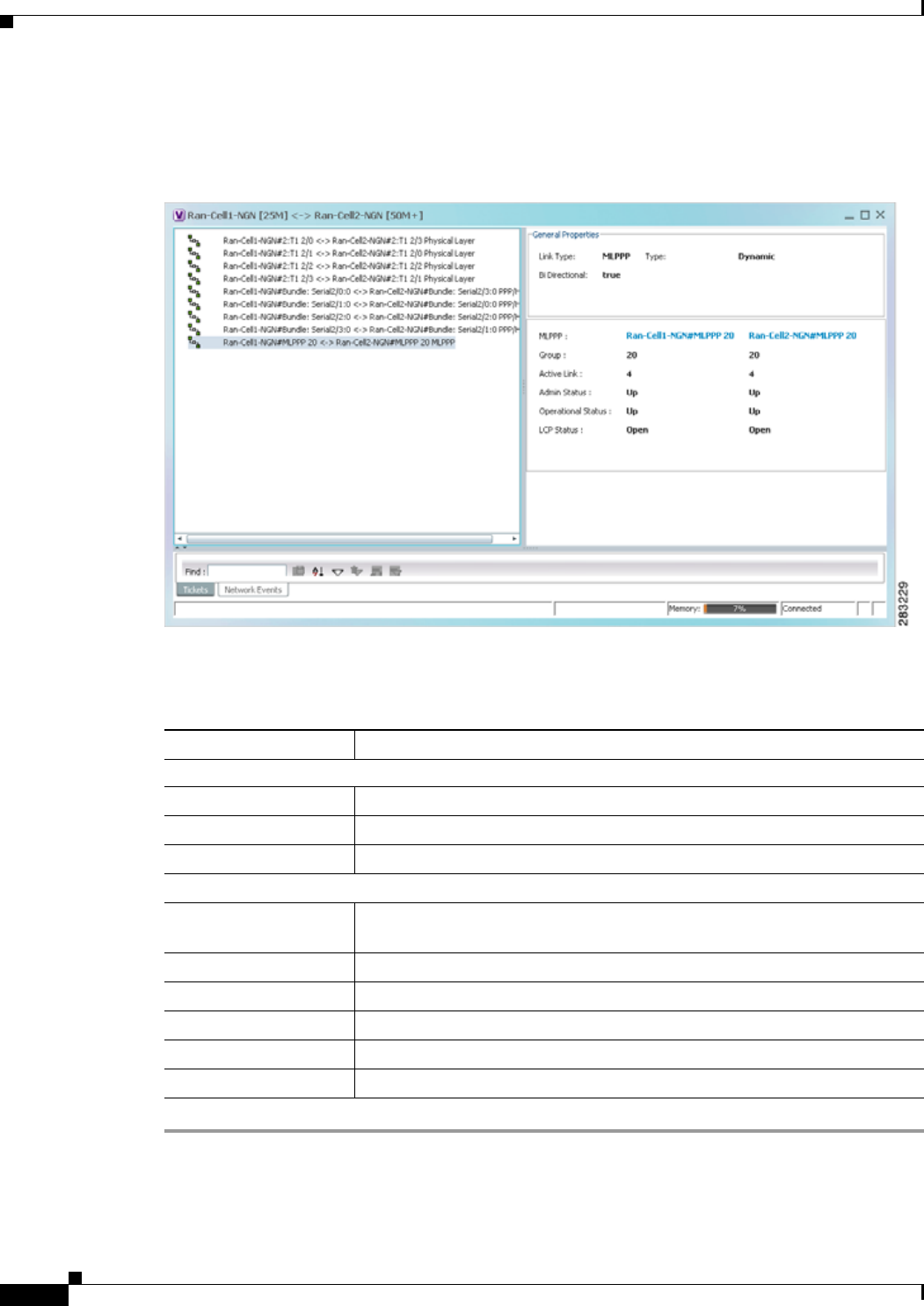
20-30
Cisco Prime Network 4.0 User Guide OL-29343-01
Chapter 20 Monitoring MToP Services
Viewing MLPPP Link Properties
Step 3 In the link properties window, select the MLPPP link. The link properties are displayed as shown in
Figure 20-16.
Figure 20-16 MLPPP Link Properties
Table 20-17 describes the information that is displayed for the MLPPP link.
Table 20-17 MLPPP Link Properties
Field Description
General Properties
Link Type Link protocol. In this case, MLPPP.
Type Type of link: Dynamic or Static.
Bi Directional Whether the link is bidirectional: True or False.
MLPPP Properties Properties are displayed for both ends of the MLPPP link.
MLPPP Interface configured for MLPPP, hyperlinked to the entry in physical
inventory.
Group MLPPP group to which the interface belongs.
Active Link Number of active interfaces participating in the MLPPP link for each device.
Admin Status Administrative status of the interface: Up or Down.
Operational Status Operational status of the interface: Up or Down.
LCP Status LCP status of the MLPPP interface: Closed, Open, Started, or Unknown.
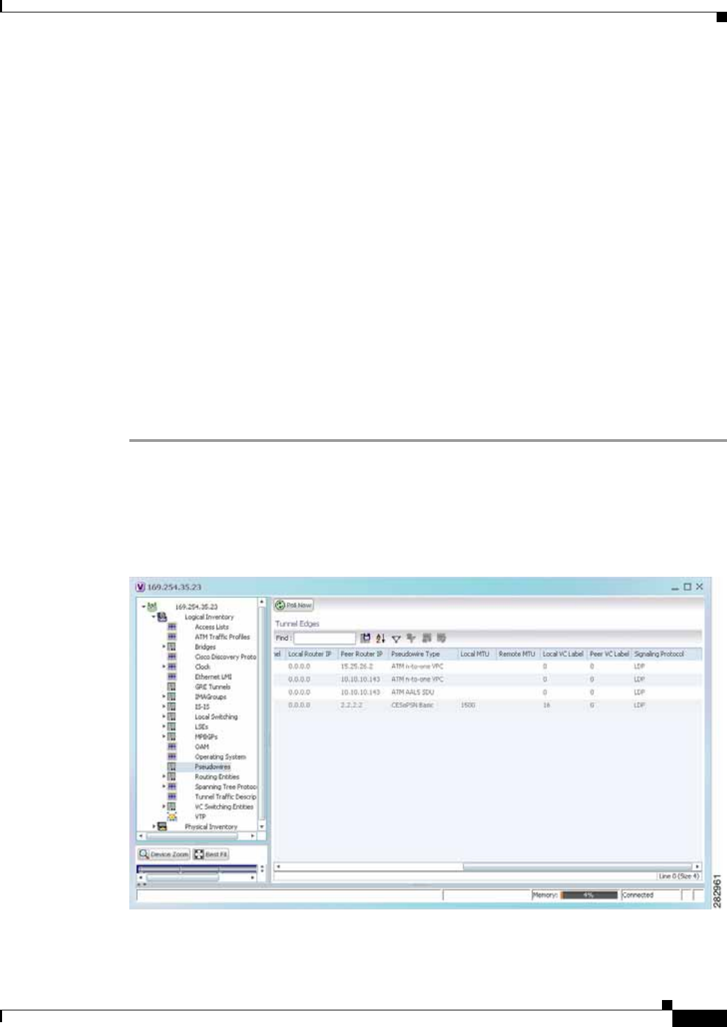
20-31
Cisco Prime Network 4.0 User Guide
OL-29343-01
Chapter 20 Monitoring MToP Services Viewing MPLS Pseudowire over GRE Properties
Viewing MPLS Pseudowire over GRE Properties
Generic routing encapsulation (GRE) is a tunneling protocol, originated by Cisco Systems and
standardized in RFC 2784. GRE encapsulates a variety of network layer packets inside IP tunneling
packets, creating a virtual point-to-point link to devices at remote points over an IP network. GRE
encapsulates the entire original packet with a standard IP header and GRE header before the IPsec
process. GRE can carry multicast and broadcast traffic, making it possible to configure a routing
protocol for virtual GRE tunnels.
In RAN backhaul networks, GRE is used to transport cell site traffic across IP networks (nonMPLS). In
addition, GRE tunnels can be used to transport TDM traffic (TDMoMPLSoGRE) as part of the
connectivity among cell site-facing Cisco 7600 routers and base station controller (BSC) site-facing
Cisco 7600 routers, or between a Cisco Mobile Wireless Router (MWR) device and a BSC site-facing
Cisco 7600 router.
Using GRE tunnels to transport Any Traffic over MPLS (AToM) enables mobile service providers to
deploy AToM pseudowires in a network where MPLS availability is discontinuous; for example, in
networks where the pseudowire endpoints are located in MPLS edge routers with a plain IP core
network, or where two separate MPLS networks are connected by a transit network with plain IP
forwarding.
To view the properties for MPLS pseudowire over GRE:
Step 1 In Prime Network Vision, right-click the required device, then choose Inventory.
Step 2 In the inventory window, choose Logical Inventory > Pseudowires. The Tunnel Edges table is
displayed in the content pane as shown in Figure 20-17.
Step 3 Select the required entry and scroll horizontally until you see the required information.
Figure 20-17 MPLS Pseudowire Tunnels over GRE Properties

20-32
Cisco Prime Network 4.0 User Guide OL-29343-01
Chapter 20 Monitoring MToP Services
Viewing MPLS Pseudowire over GRE Properties
Table 20-18 describes the information included in the Tunnel Edges table specifically for MPLS
pseudowire tunnels over GRE.
Step 4 To view GRE Tunnel properties, choose Logical Inventory > GRE Tunnels.
Figure 20-18 shows the Tunnel Edges table that is displayed for GRE tunnels.
Table 20-18 MPLS Pseudowire over GRE Properties
Field Description
Pseudowire Type Type of pseudowire relevant to MToP:
• ATM AAL5 SDU—ATM with ATM Adaptation Layer 5
(AAL5) service data units.
• ATM n-to-one VCC—ATM with n-to-one virtual channel
connection (VCC).
• ATM n-to-one VPC—ATM with n-to-one virtual path
connection (VPC).
• CESoPSN Basic—CESoPSN basic services with CAS.
• SAToP E1—SAToP on an E1 interface.
Local MTU Size, in bytes, of the MTU on the local interface.
Remote MTU Size, in bytes, of the MTU on the remote interface.
Preferred Path Tunnel Path to be used for MPLS pseudowire traffic.
Click the hyperlinked entry to view the tunnel details in logical
inventory.
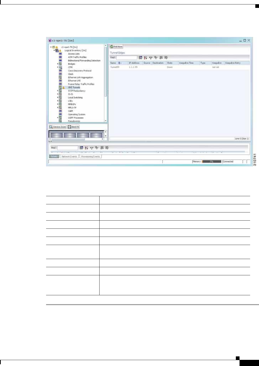
20-33
Cisco Prime Network 4.0 User Guide
OL-29343-01
Chapter 20 Monitoring MToP Services Viewing MPLS Pseudowire over GRE Properties
Figure 20-18 GRE Tunnel Properties in Logical Inventory
Table 20-19 describes the information that is displayed for GRE tunnels in logical inventory.
Table 20-19 GRE Tunnel Properties in Logical Inventory
Field Description
Name Tunnel name.
IP Address Tunnel IP address.
Source IP address local to the device.
Destination IP address of the remote router.
State State of the tunnel: Up or Down.
Keepalive Time If keepalive is enabled, the amount of time, in seconds, to wait before
sending a keepalive message.
Type Tunnel type.
Keepalive Status of the keepalive function: Set, Not Set, or Unknown.
Keepalive Retry Number times that the device continues to send keepalive packets
without response before bringing the tunnel interface protocol down.
Values range from 2 to 254, with a default of 3.

20-34
Cisco Prime Network 4.0 User Guide OL-29343-01
Chapter 20 Monitoring MToP Services
Network Clock Service Overview
Network Clock Service Overview
Network clock service refers to the means by which a clock signal is generated or derived and distributed
through a network and its individual nodes for the purpose of ensuring synchronized network operation.
Network clocking is particularly important for mobile service providers to ensure proper transport of
cellular traffic from cell sites to Base Station Control (BSC) sites.
Note In Prime Network Vision, clock service refers to network clock service.
The following topics describe how to use Prime Network Vision to monitor clock service:
• Monitoring Clock Service, page 20-34
• Monitoring PTP Service, page 20-36
• Viewing Pseudowire Clock Recovery Properties, page 20-41
• Viewing SyncE Properties, page 20-45
• Applying a Network Clock Service Overlay, page 20-48
• Viewing CEM and Virtual CEM Properties, page 20-49
Monitoring Clock Service
To monitor clock service:
Step 1 In Prime Network Vision, right-click the required device, then choose Inventory.
Step 2 In the inventory window, choose Logical Inventory > Clock. Clock service information is displayed in
the content pane as shown in Figure 20-19.
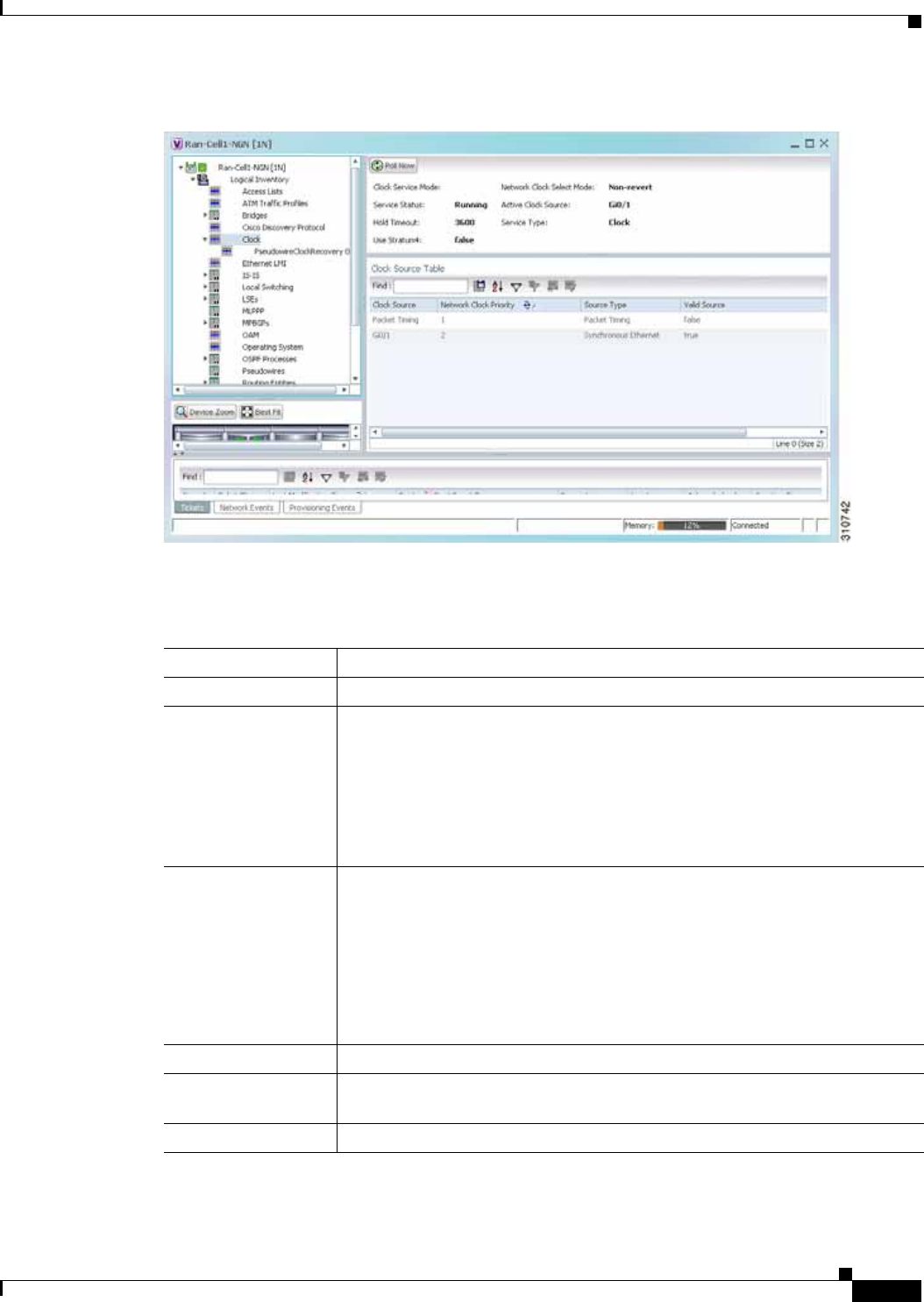
20-35
Cisco Prime Network 4.0 User Guide
OL-29343-01
Chapter 20 Monitoring MToP Services Network Clock Service Overview
Figure 20-19 Clock Service Properties
Table 20-20 describes the information displayed for clocking service.
Table 20-20 Clock Service Properties
Field Description
Clock Service Mode This field is not populated.
Network Clock Select
Mode Action to take if the master device fails:
• Non-revert—Do not use the master device again after it recovers from the
failure.
• Revert—Use the master device again after it recovers and functions
correctly for a specified amount of time.
• Unknown—The network clock selection mode is unknown.
Service Status Status of the system service:
• Initializing—The service is starting up.
• Down—The service is down.
• Reset—The service has been reset.
• Running—The service is running.
• Other—A status other than those listed.
Active Clock Source Current active clock source used by the device.
Hold Timeout How long the device waits before reevaluating the network clock entry. Values
can be from 0-86400 seconds, Not Set, or infinite.
Service Type Type of system service, such as Clock or Cisco Discovery Protocol.

20-36
Cisco Prime Network 4.0 User Guide OL-29343-01
Chapter 20 Monitoring MToP Services
Network Clock Service Overview
Monitoring PTP Service
In networks that employ TDM, periodic synchronization of device clocks is required to ensure that the
receiving device knows which channel is which for accurate reassembly of the data stream. The
Precision Time Protocol (PTP) standard:
• Specifies a clock synchronization protocol that enables this synchronization.
• Applies to distributed systems that consist of one or more nodes communicating over a network.
Defined by IEEE 1588-2008, PTP Version 2 (PTPv2) allows device synchronization at the nanosecond
level.
PTP uses the concept of master and slave devices to achieve precise clock synchronization. Using PTP,
the master device periodically starts a message exchange with the slave devices. After noting the times
at which the messages are sent and received, each slave device calculates the difference between its
system time and the system time of the master device. The slave device then adjusts its clock so that it
is synchronized with the master device. When the master device initiates the next message exchange, the
slave device again calculates the difference and adjusts its clock. This repetitive synchronization ensures
that device clocks are coordinated and that data stream reassembly is accurate. For configuring PTP, see
Configuring SONET, page 20-53.
Use Stratum4 Quality of the clock source:
• True—Use Stratum 4, the lowest level of clocking quality.
• False—(Default) Use Stratum 3, a higher level of clocking quality than
Stratum 4.
Clock Source Table This table is displayed only if there are active clock sources.
Clock Source Current active clock source used by the device.
Network Clock
Priority Priority of the clock source with 1 being the highest priority.
Source Type Method by which clocking information is provided:
• BITS—Timing is supplied by a Building Integrated Timing Supply (BITS)
port clock.
• E1/T1—Clocking is provided via an E1 or T1 interface.
• Packet-Timing—Clocking is provided over a packet-based network.
• Synchronous Ethernet—Clocking is provided by Synchronous Ethernet.
• Others—Clocking is provided by a source other than the above.
Valid Source Validity of the clock source:
• True—The clock source is valid and operational.
• False—The clock source is not valid or is not operational.
Table 20-20 Clock Service Properties (continued)
Field Description
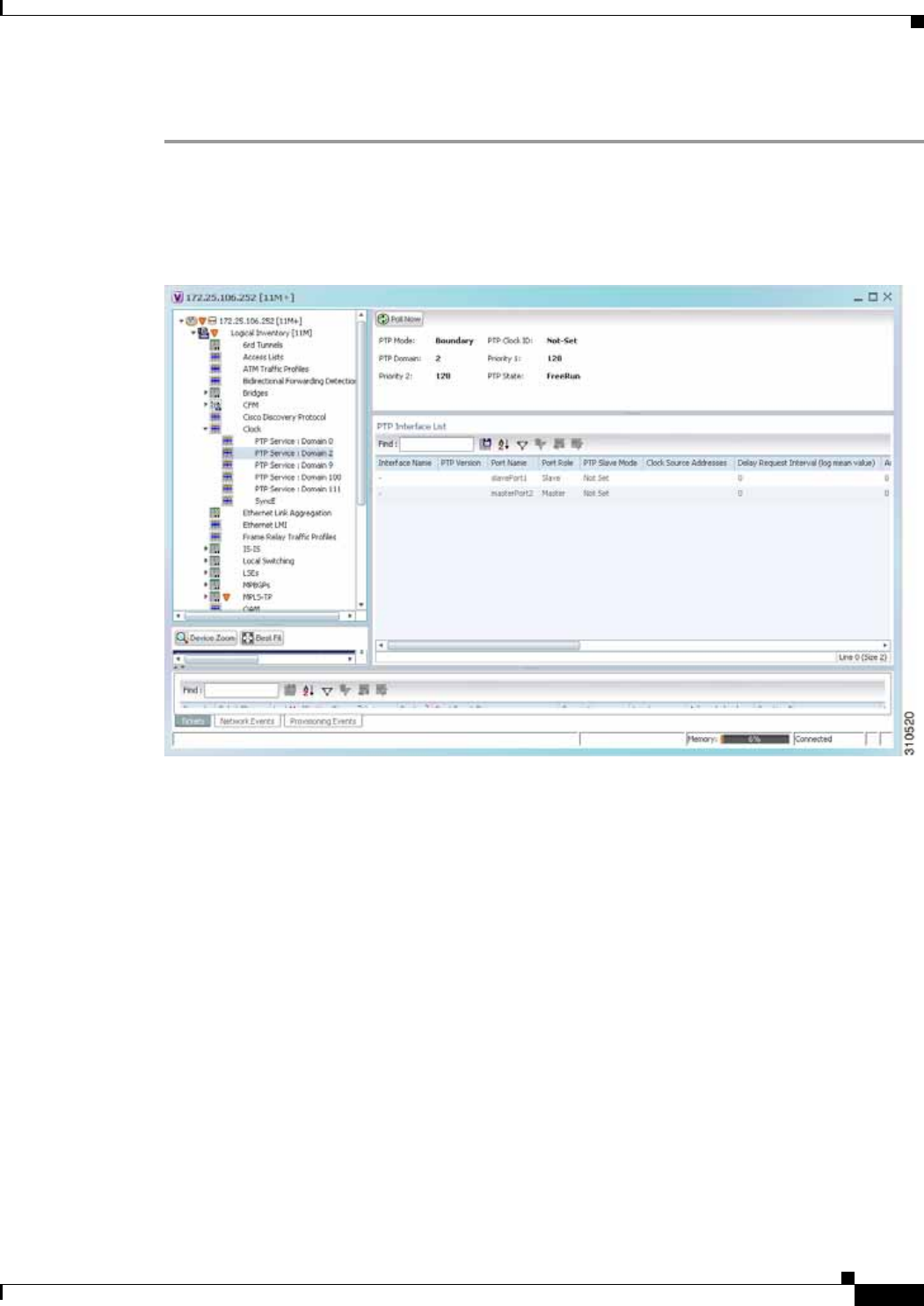
20-37
Cisco Prime Network 4.0 User Guide
OL-29343-01
Chapter 20 Monitoring MToP Services Network Clock Service Overview
To monitor PTP service:
Step 1 In Prime Network Vision, right-click the required device, then choose Inventory.
Step 2 In the inventory window, choose Logical Inventory > Clock > PTP Service. The PTP service
properties are displayed in the content pane as shown in Figure 20-20.
Figure 20-20 PTP Service Properties
Table 20-21 describes the properties that are displayed for PTP service.

20-38
Cisco Prime Network 4.0 User Guide OL-29343-01
Chapter 20 Monitoring MToP Services
Network Clock Service Overview
Table 20-21 PTP Service Properties
Field Description
PTP Mode Mode of PTP operation:
• Boundary—Boundary clock mode.
• E2E Transparent—End-to-end transparent clock mode.
• Ordinary—Ordinary clock mode.
• P2P Transparent—Peer-to-peer transparent clock mode.
• Unknown—The clock mode is unknown.
Note Cisco MWR-2941 routers support Ordinary mode only.
PTP Clock ID Clock identifier derived from the device interface.
PTP Domain Number of the domain used for PTP traffic. A single network can contain
multiple separate domains.
Priority 1 First value checked for clock selection. The clock with the lowest priority takes
precedence.
Priority 2 If two or more clocks have the same value in the Priority 1 field, the value in this
field is used for clock selection.
Port State Clock state according to the PTP engine:
• Freerun—The slave clock is not locked to a master clock.
• Holdover—The slave device is locked to a master device, but communication
with the master is lost or the timestamps in the PTP packet are incorrect.
• Acquiring—The slave device is receiving packets from a master and is trying
to acquire a clock.
• Freq locked—The slave device is locked to the master device with respect to
frequency, but is not aligned with respect to phase.
• Phase aligned—The slave device is locked to the master device with respect
to both frequency and phase.
PTP Interface List Table
Interface Name Interface identifier.
PTP Version Version of PTP used. The default value is 2, indicating PTPv2.
Port Name Name of the PTP port clock.
Port Role PTP role of the clock: Master or Slave.
PTP Slave Mode For an interface defined as a slave device, the mode used for PTP clocking:
• Not Set—The slave mode is not used.
• Multicast—The interface uses multicast mode for PTP clocking.
• Unicast—The interface uses unicast mode for PTP clocking.
• Unicast with Negotiation—The interface uses unicast mode with negotiation
for PTP clocking.
Clock Source
Addresses IP addresses of the clock source.

20-39
Cisco Prime Network 4.0 User Guide
OL-29343-01
Chapter 20 Monitoring MToP Services Network Clock Service Overview
Delay Request
Interval (log mean
value)
When the interface is in PTP master mode, the interval specified to member
devices for delay request messages. The intervals use base 2 values, as follows:
• 4—1 packet every 16 seconds.
• 3—1 packet every 8 seconds.
• 2—1 packet every 4 seconds.
• 1—1 packet every 2 seconds.
• 0—1 packet every second.
• -1—1 packet every 1/2 second, or 2 packets per second.
• -2—1 packet every 1/4 second, or 4 packets per second.
• -3—1 packet every 1/8 second, or 8 packets per second.
• -4—1 packet every 1/16 seconds, or 16 packets per second.
• -5—1 packet every 1/32 seconds, or 32 packets per second.
• -6—1 packet every 1/64 seconds, or 64 packets per second.
Announce Interval
(log mean value) Interval value for PTP announcement packets:
• 4—1 packet every 16 seconds.
• 3—1 packet every 8 seconds.
• 2—1 packet every 4 seconds.
• 1—1 packet every 2 seconds.
• 0—1 packet every second.
• -1—1 packet every 1/2 second, or 2 packets per second.
• -2—1 packet every 1/4 second, or 4 packets per second.
• -3—1 packet every 1/8 second, or 8 packets per second.
• -4—1 packet every 1/16 seconds, or 16 packets per second.
• -5—1 packet every 1/32 seconds, or 32 packets per second.
• -6—1 packet every 1/64 seconds, or 64 packets per second.
Announce Timeout Number of PTP announcement intervals before the session times out. Values are
2-10.
Table 20-21 PTP Service Properties (continued)
Field Description

20-40
Cisco Prime Network 4.0 User Guide OL-29343-01
Chapter 20 Monitoring MToP Services
Network Clock Service Overview
Sync Interval (log
mean value) Interval for sending PTP synchronization messages:
• 4—1 packet every 16 seconds.
• 3—1 packet every 8 seconds.
• 2—1 packet every 4 seconds.
• 1—1 packet every 2 seconds.
• 0—1 packet every second.
• -1—1 packet every 1/2 second, or 2 packets per second.
• -2—1 packet every 1/4 second, or 4 packets per second.
• -3—1 packet every 1/8 second, or 8 packets per second.
• -4—1 packet every 1/16 seconds, or 16 packets per second.
• -5—1 packet every 1/32 seconds, or 32 packets per second.
• -6—1 packet every 1/64 seconds, or 64 packets per second.
Sync Limit
(nanoseconds) Maximum clock offset value, in nanoseconds, before PTP attempts to
resynchronize.
Interface Physical interface identifier, hyperlinked to the routing information for the
interface.
PTP Master Mode For an interface defined as a master device, the mode used for PTP clocking:
• Not Set—The master mode is not used.
• Multicast—The interface uses multicast mode for PTP clocking.
• Unicast—The interface uses unicast mode for PTP clocking. This mode
allows a single destination.
• Unicast with Negotiation—The interface uses unicast mode with negotiation
for PTP clocking. This mode allows up to 128 destinations.
Clock Destination
Addresses IP addresses of the clock destinations. This field contains IP addresses only when
Master mode is enabled.
Domain Clocking domain.
Table 20-21 PTP Service Properties (continued)
Field Description
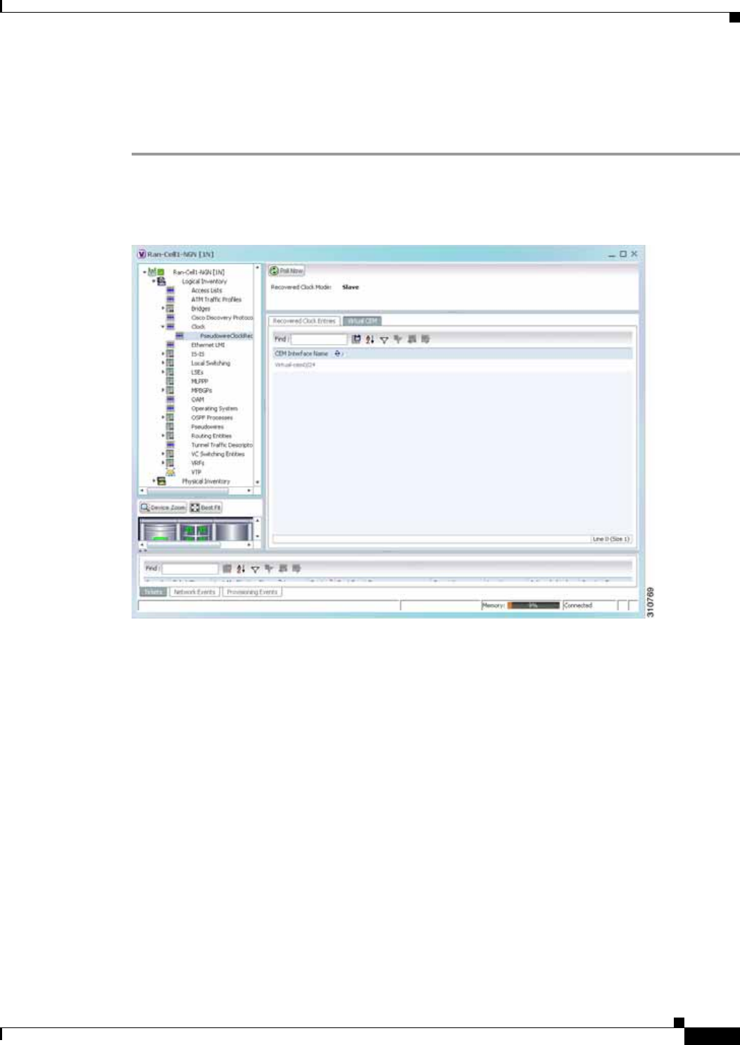
20-41
Cisco Prime Network 4.0 User Guide
OL-29343-01
Chapter 20 Monitoring MToP Services Network Clock Service Overview
Viewing Pseudowire Clock Recovery Properties
To view pseudowire clock recovery properties:
Step 1 Choose Logical Inventory > Clock > Pseudowire Clock Recovery. Prime Network Vision displays the
Virtual CEM information by default. See Figure 20-21.
Figure 20-21 Pseudowire Clock Recovery - Virtual CEM Tab
Step 2 To view more information about a virtual CEM, right-click the virtual CEM, then choose Properties.
The Virtual CEM Properties window is displayed.
The information that is displayed in the Virtual CEM Properties window depends on whether or not the
virtual CEM belongs to a group:
• If a CEM group is not configured on the virtual CEM, the Virtual CEM Properties window contains
only the CEM interface name.
• If a CEM group is configured on the virtual CEM, the Virtual CEM Properties window contains the
information described in Table 20-22.

20-42
Cisco Prime Network 4.0 User Guide OL-29343-01
Chapter 20 Monitoring MToP Services
Network Clock Service Overview
Step 3 To view additional CEM group properties, double-click the required CEM group.
Table 20-23 describes the information displayed in the CEM Group Properties window.
Table 20-22 Virtual CEM Group Properties
Field Description
CEM Interface Name CEM interface name.
CEM Group Table
CEM Group Name of the virtual CEM group.
Framing Framing mode used for the CEM channel:
• Framed—Specifies the channels used for the controller, such as
Channels: (1-8), (10-14). The channels that are available
depend on the type of controller: T1, E1, T3, or E3.
• Unframed—Indicates that a single CEM channel is used for all
T1/E1 timeslots. SAToP uses the unframed mode.
Pseudowire Name of the pseudowire configured on the CEM interface,
hyperlinked to the pseudowire properties in logical inventory.
Oper Status Operational status of the CEM interface:
• Dormant—The interface is dormant.
• Down—The interface is down.
• Not Present—An interface component is missing.
• Testing—The interface is in test mode.
• Unknown—The interface has an unknown operational status.
• Up—The interface is up.
Admin Status Administrative status of the CEM interface:
• Down—The CEM interface is administratively down.
• Testing—The administrator is testing the CEM interface.
• Unknown—The administrative status is unknown.
• Up—The CEM interface is administratively up.

20-43
Cisco Prime Network 4.0 User Guide
OL-29343-01
Chapter 20 Monitoring MToP Services Network Clock Service Overview
Step 4 To view recovered clock entries, click the Recovered Clock Entries tab. See Figure 20-22.
If no recovered clock entries exist, this tab is not displayed.
Table 20-23 CEM Group Properties
Field Description
Oper Status Operational status of the CEM interface:
• Dormant—The interface is dormant.
• Down—The interface is down.
• Not Present—An interface component is missing.
• Testing—The interface is in test mode.
• Unknown—The interface has an unknown operational status.
• Up—The interface is up.
Idle Pattern Eight-bit hexadecimal number that is transmitted on a T1 or E1 line
when missing packets are detected on the pseudowire (PW) circuit.
Type Type of CEM group. This is always DS0 Bundle.
Idle CAS Pattern When CAS is used, the 8-bit hexadecimal signal that is sent when
the CEM interface is identified as idle.
Bundle Location Associated card and slot for the virtual CEM, using the virtual CEM
port 24; for example virtual-cem/8/3/24:0.
Dejitter Size of the dejitter buffer in milliseconds (ms). The range is 4 to 500
ms with a default of 4 ms.
RTP Hdr Compression Whether RTP header compression is enabled or disabled.
RTP Enabled Whether RTP compression is enabled or disabled.
Admin Status Administrative status of the CEM interface:
• Down—The CEM interface is administratively down.
• Testing—The administrator is testing the CEM interface.
• Unknown—The administrative status is unknown.
• Up—The CEM interface is administratively up.
ID DS0 bundle CEM group identifier.
Payload Size Size of the payload for packets on the CEM interface. The range is
32 to 1312 bytes.
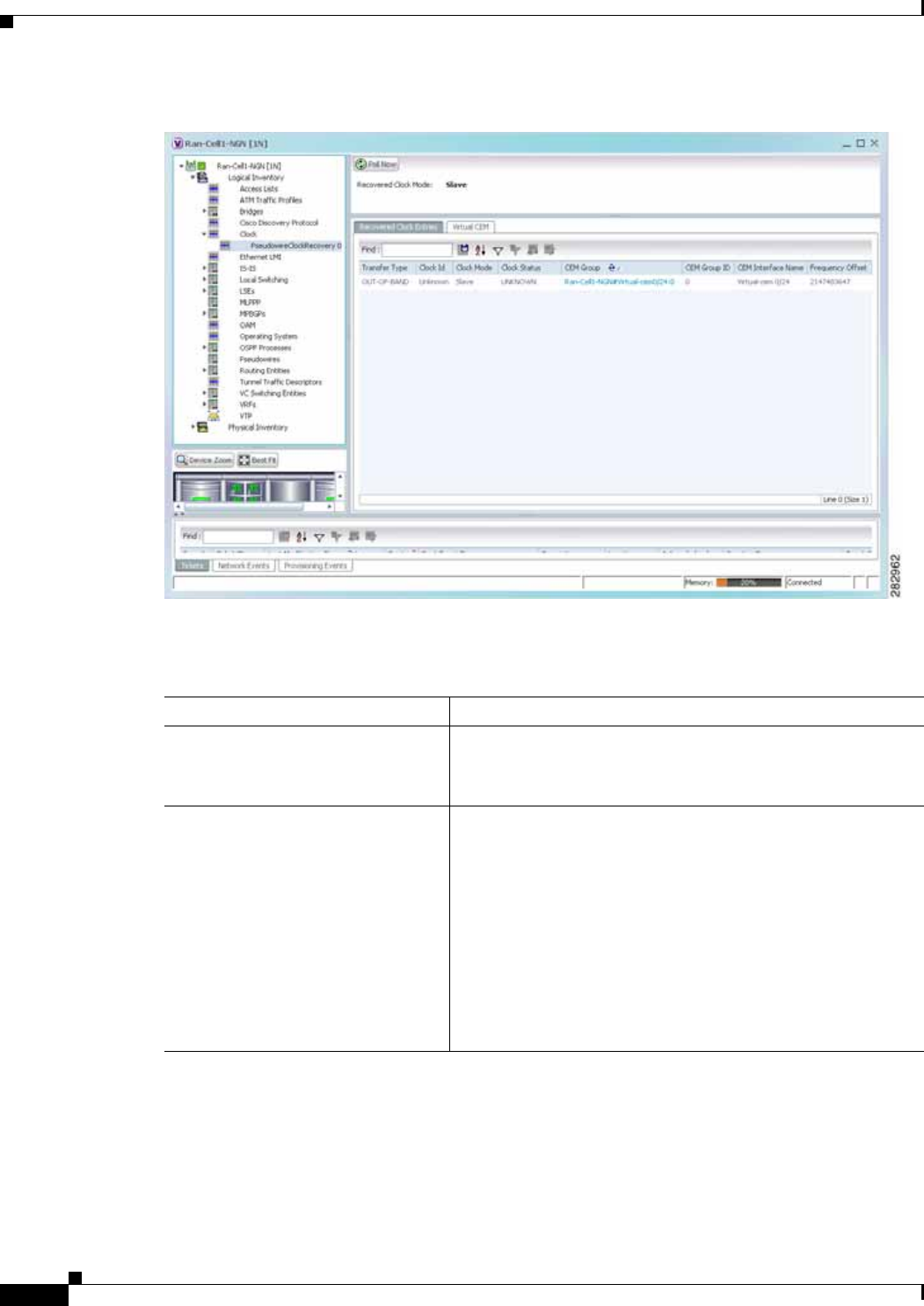
20-44
Cisco Prime Network 4.0 User Guide OL-29343-01
Chapter 20 Monitoring MToP Services
Network Clock Service Overview
Figure 20-22 Pseudowire Clock Recovery - Recovered Clock Entries Tab
Table 20-24 describes the information displayed for pseudowire clock recovery.
Table 20-24 Pseudowire Clock Recovery Properties
Field Description
Recovered Clock Source Interface (slot/subslot) in which clock recovery occurred.
Click the hyperlinked entry to view its properties in physical
inventory.
Recovered Clock Mode Recovered clock mode:
• Adaptive—The devices do not have a common clock
source. The recovered clock is derived from packet arrival.
• Differential—The edge devices have a common clock
source, and the recovered clock is derived from timing
information in packets and the related difference from the
common clock.
• Synchronous—A GPS or BITS clock source externally
synchronizes both end devices. This method is extremely
accurate, but is rarely available for all network devices.

20-45
Cisco Prime Network 4.0 User Guide
OL-29343-01
Chapter 20 Monitoring MToP Services Network Clock Service Overview
Viewing SyncE Properties
With Ethernet equipment gradually replacing SONET and SDH equipment in service-provider networks,
frequency synchronization is required to provide high-quality clock synchronization over Ethernet ports.
Synchronous Ethernet (SyncE), a recently adopted standard, provides the required synchronization at the
physical level.
In SyncE, Ethernet links are synchronized by timing their bit clocks from high-quality,
stratum-1-traceable clock signals in the same manner as SONET/SDH. Operations messages maintain
SyncE links, and ensure a node always derives timing from the most reliable source.
For configuring SyncE, see Configuring Clock, page 20-55. To view SyncE properties, choose Logical
Inventory > Clock > SyncE. (See Figure 20-23.)
Virtual CEM Tab
CEM Interface Name Virtual CEM interface associated with the clock.
Recovered Clock Entries Tab This tab appears if recovered entries exist.
Transfer Type • In-band—The clocking information is sent over the same
pseudowire as the bearer traffic.
• Out-of-band—The clocking information is sent over a
dedicated pseudowire between the sending and receiving
SPAs.
Clock ID Clock identifier, if known.
Clock Mode Clock mode of the recovered clock:
• Adaptive—The recovered clock was obtained using ACR.
• Primary—The recovered clock was obtained from a clock
with the highest priority.
• Secondary—The recovered clock was obtained from a
clock with a lower priority than the primary clock.
Clock Status Status of the clock:
• Acquiring—The clock is obtaining clocking information.
• Acquired—The clock has obtained the required clocking
information.
• Holdover—The current primary clock is invalid and a
holdover timer has started to check whether or not the clock
becomes valid within the specified holdover time.
CEM Group CEM group associated with the clock.
CEM Group ID Identifier of the CEM group associated with the clock.
CEM Interface Name Virtual CEM interface associated with the clock.
Frequency Offset Offset to the clock frequency, in Hz.
Table 20-24 Pseudowire Clock Recovery Properties (continued)
Field Description
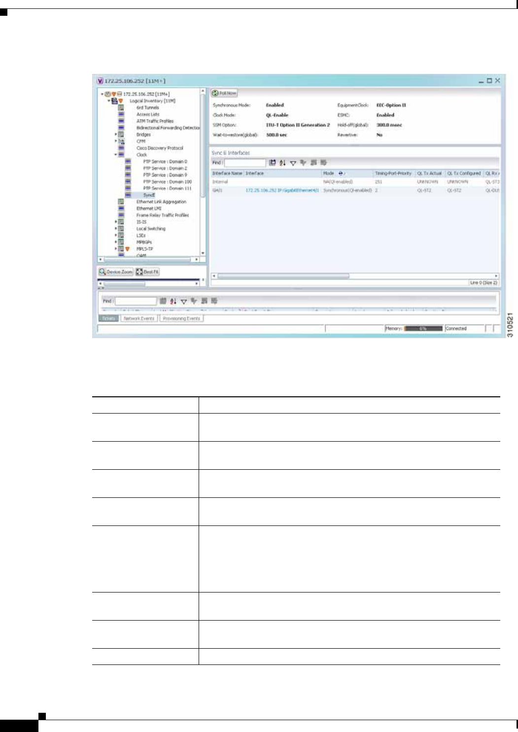
20-46
Cisco Prime Network 4.0 User Guide OL-29343-01
Chapter 20 Monitoring MToP Services
Network Clock Service Overview
Figure 20-23 SyncE Properties in Logical Inventory
Table 20-25 describes the information that is displayed for SyncE.
Table 20-25 SyncE Properties
Field Description
Synchronous Mode Status of the automatic synchronization selection process: Enabled or
Disable.
Equipment Clock Ethernet Equipment Clock (EEC) options: EEC-Option I or
EEC-Option II.
Clock Mode Whether the clock is enabled or disabled for the Quality Level (QL)
function: QL-Enabled or QL-Disabled.
ESMC Ethernet Synchronization Message Channel (ESMC) status: Enabled or
Disabled.
SSM Option Synchronization Status Message (SSM) option being used:
• ITU-T Option I
• ITU-T Option II Generation 1
• ITU-T Option II Generation 2
Hold-off (global) Length of time (in milliseconds) to wait before issuing a protection
response to a failure event.
Wait-to-restore (global) Length of time (in seconds) to wait after a failure is fixed before the span
returns to its original state.
Revertive Whether the network clock is to use revertive mode: Yes or No.

20-47
Cisco Prime Network 4.0 User Guide
OL-29343-01
Chapter 20 Monitoring MToP Services Network Clock Service Overview
SyncE Interfaces Table
Interface Name Name of the Gigabit or 10 Gigabit interface associated with SyncE.
If SyncE is not associated with a Gigabit or 10 Gigabit interface, this
field contains Internal.
Interface Hyperlinked entry to the interface routing information in the Routing
Entity Controller window. For more information, see Viewing Routing
Entities, page 18-31.
This field does not apply for Internal interfaces.
Mode Whether the interface is enabled or disabled for the QL function:
QL-Enabled or QL-Disabled.
Timing Port Priority Value used for selecting a SyncE interface for clocking if more than one
interface is configured. Values are from 1 to 250, with 1 being the
highest priority.
QL Tx Actual Actual type of outgoing quality level information, depending on the
globally configured SSM option:
• ITU-T Option I—Available values are QL-PRC, QL-SSU-A,
QL-SSU-B, QL-SEC, and QL-DNU.
• ITU-T Option II Generation 1—Available values are QL-PRS,
QL-STU, QL-ST2, QL-SMC, QL-ST4, and QL-DUS.
• ITU-T Option II Generation 2—Available values are QL-PRS,
QL-STU, QL-ST2, QL-TNC, QL-ST3, QL-SMC, QL-ST4, and
QL-DUS.
QL Tx Configured Configured type of outgoing quality level information, depending on the
globally configured SSM option.
See QL Tx Actual for the available values.
QL Rx Actual Actual type of incoming quality level information, depending on the
globally configured SSM option.
See QL Tx Actual for the available values.
QL Rx Configured Configured type of incoming quality level information, depending on
the globally configured SSM option.
See QL Tx Actual for the available values.
Hold-Off Timer (msecs) Length of time (in milliseconds) to wait after a clock source goes down
before removing the source.
Wait-to-Restore (secs) Length of time (in seconds) to wait after a failure is fixed before the
interface returns to its original state.
Table 20-25 SyncE Properties (continued)
Field Description

20-48
Cisco Prime Network 4.0 User Guide OL-29343-01
Chapter 20 Monitoring MToP Services
Network Clock Service Overview
Applying a Network Clock Service Overlay
A service overlay allows you to isolate the parts of a network that are being used by a particular service.
This information can then be used for troubleshooting. For example, the overlay can highlight
configuration or design problems when bottlenecks occur and all the site interlinks use the same link.
To apply a network clock overlay:
Step 1 In Prime Network Vision, display the network map on which you want to apply an overlay.
Step 2 From the main toolbar, click Choose Overlay Type and choose Network Clock.
The Select Network Clock Service Overlay dialog box is displayed.
Step 3 Do one of the following:
• Choose a search category, enter a search string, then click Go to narrow the search results to a range
of network clock services or a specific network clock service. Search categories include:
–
Description
–
Name
The search condition is “contains.” Search strings are case-insensitive. For example, if you choose
the Name category and enter “net,” Prime Network Vision displays network clock services that have
“net” in their names whether net appears at the beginning of the name, the middle, or at the end: for
example, Ethernet.
• Choose Show All to display all network clock services.
Step 4 Select the network clock service overlay that you want to apply to the map.
The elements and links used by the selected network clock are highlighted in the map, and the overlay
name is displayed in the title of the window. (See Figure 20-24.)
ESMC Tx Whether ESMC is enabled for outgoing QL information on the interface:
Enabled, Disabled, or NA (Not Available).
ESMC Rx Whether ESMC is enabled for incoming QL information on the
interface: Enabled, Disabled, or NA (Not Available).
SSM Tx Whether SSM is enabled for outgoing QL information on the interface:
Enabled, Disabled, or NA (Not Available).
SSM Rx Whether SSM is enabled for incoming QL information on the interface:
Enabled, Disabled, or NA (Not Available).
Table 20-25 SyncE Properties (continued)
Field Description
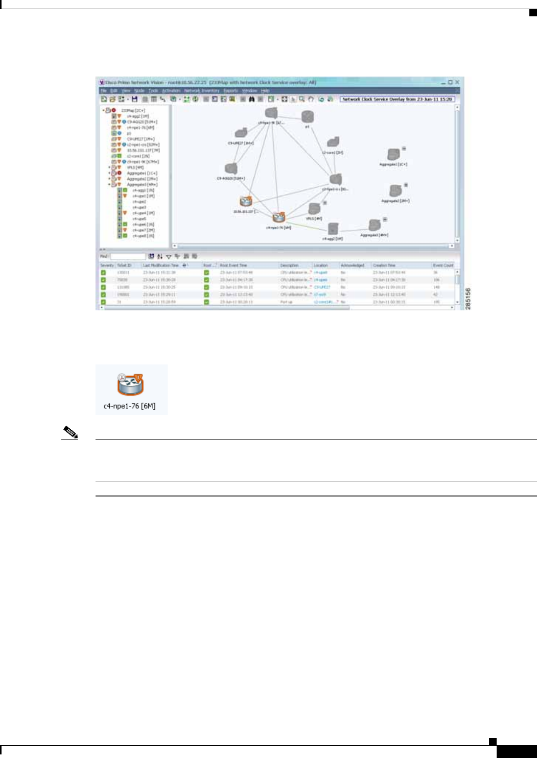
20-49
Cisco Prime Network 4.0 User Guide
OL-29343-01
Chapter 20 Monitoring MToP Services Viewing CEM and Virtual CEM Properties
Figure 20-24 Network Clock Service Overlay Example
In addition, the elements configured for clocking service display a clock service icon as in the following
example:
Note An overlay is a snapshot taken at a specific point in time and does not reflect changes that occur in the
service. As a result, the information in an overlay can become stale. To update the overlay, click Refresh
Overlay in the main toolbar.
Viewing CEM and Virtual CEM Properties
The following topics describe how to view CEM and virtual CEM properties and interfaces:
• Viewing CEM Interfaces, page 20-50
• Viewing Virtual CEMs, page 20-50
• Viewing CEM Groups, page 20-50
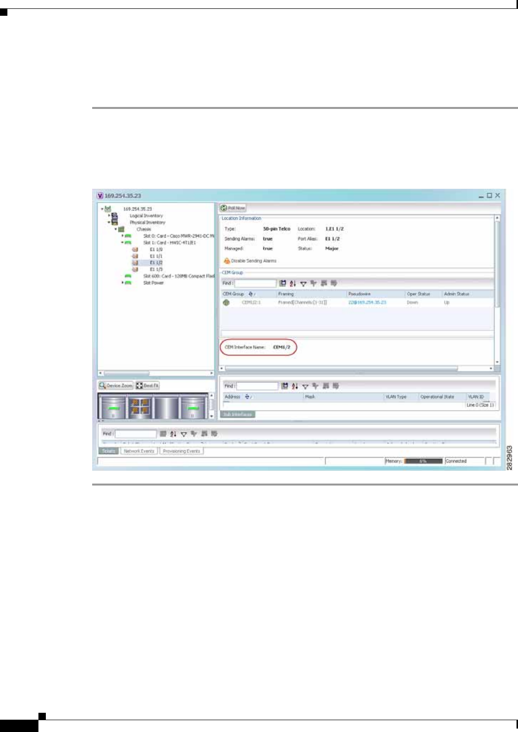
20-50
Cisco Prime Network 4.0 User Guide OL-29343-01
Chapter 20 Monitoring MToP Services
Viewing CEM and Virtual CEM Properties
Viewing CEM Interfaces
To view CEM interfaces:
Step 1 In Prime Network Vision, double-click the required device.
Step 2 In the inventory window, choose Physical Inventory > Chassis > slot > subslot > interface. The CEM
interface name is displayed in the content pane as shown in Figure 20-25.
Figure 20-25 CEM Interface
Viewing Virtual CEMs
To view virtual CEMs, choose Logical Inventory > Clock > Pseudowire Clock Recovery.
The virtual CEM interfaces are listed in the Virtual CEM tab.
Viewing CEM Groups
CEM groups can be configured on physical or virtual CEM interfaces. The underlying interface
determines where you view CEM group properties in Prime Network Vision:
• Viewing CEM Groups on Physical Interfaces, page 20-51
• Viewing CEM Groups on Virtual CEM Interfaces, page 20-52
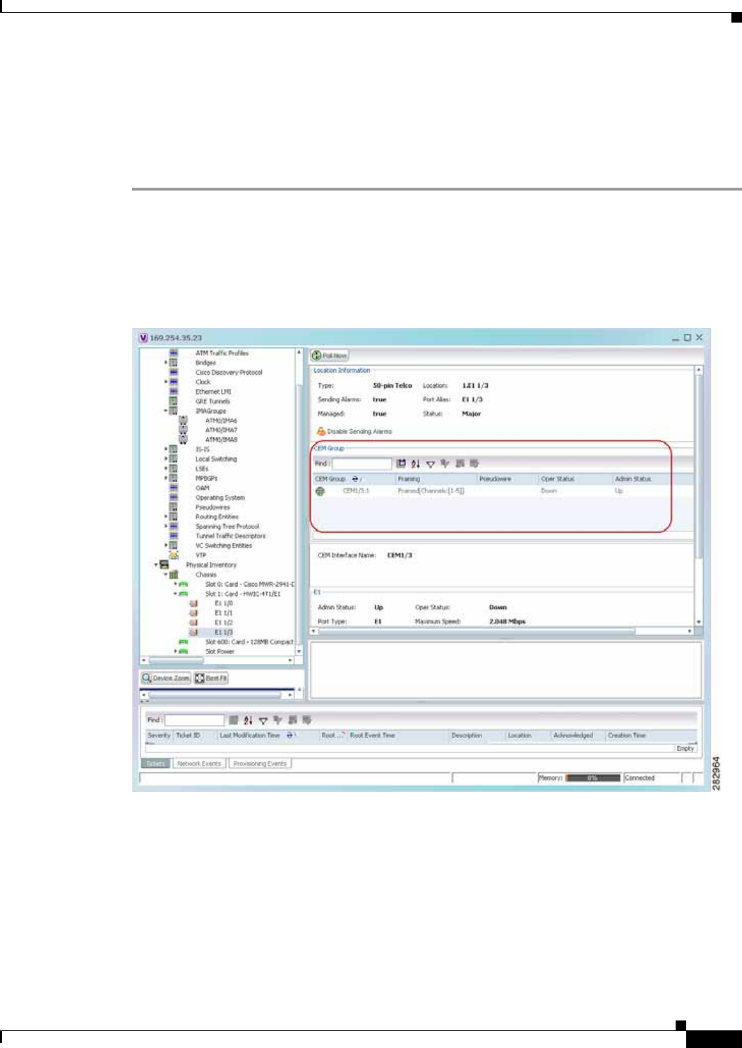
20-51
Cisco Prime Network 4.0 User Guide
OL-29343-01
Chapter 20 Monitoring MToP Services Viewing CEM and Virtual CEM Properties
Viewing CEM Groups on Physical Interfaces
When you configure a CEM group on a physical interface, the CEM group properties are displayed in
physical inventory for that interface.
To view CEM groups configured on physical interfaces:
Step 1 In Prime Network Vision, double-click the required device.
Step 2 In the inventory window, choose Physical Inventory > Chassis > slot > subslot > interface.
The CEM group information is displayed in the content pane with other interface properties
(Figure 20-26).
Figure 20-26 CEM Group Information
See Table 20-22 for a description of the properties displayed for CEM groups in the content pane.
Step 3 To view additional information, double-click the required group.
The CEM Group Properties window is displayed as shown in Figure 20-27.
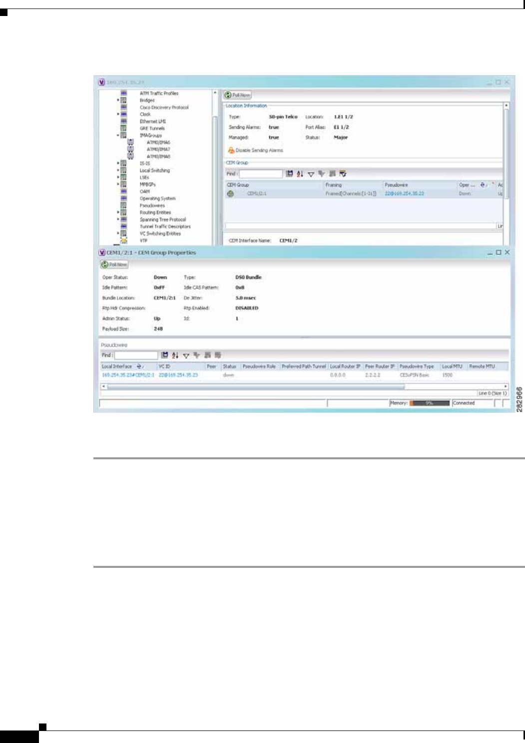
20-52
Cisco Prime Network 4.0 User Guide OL-29343-01
Chapter 20 Monitoring MToP Services
Viewing CEM and Virtual CEM Properties
Figure 20-27 CEM Group Properties Window
See Table 18-27 on page 18-51 for the properties displayed in the Pseudowire table in the CEM Group
Properties window.
Viewing CEM Groups on Virtual CEM Interfaces
When you configure a CEM group on a virtual CEM, the CEM group information is displayed below the
virtual CEM in logical inventory.
To view CEM groups on virtual CEM interfaces:
Step 1 In Prime Network Vision, right-click the required device, then choose Inventory.
Step 2 In the inventory window, choose Logical Inventory > Clock > Pseudowire Clock Recovery.
Step 3 In the Virtual CEM tab, right-click the CEM interface name and choose Properties. The CEM group
properties are displayed in a separate window (Figure 20-28). If a pseudowire is configured on the CEM
group for out-of-band clocking, the pseudowire VCID is also shown.
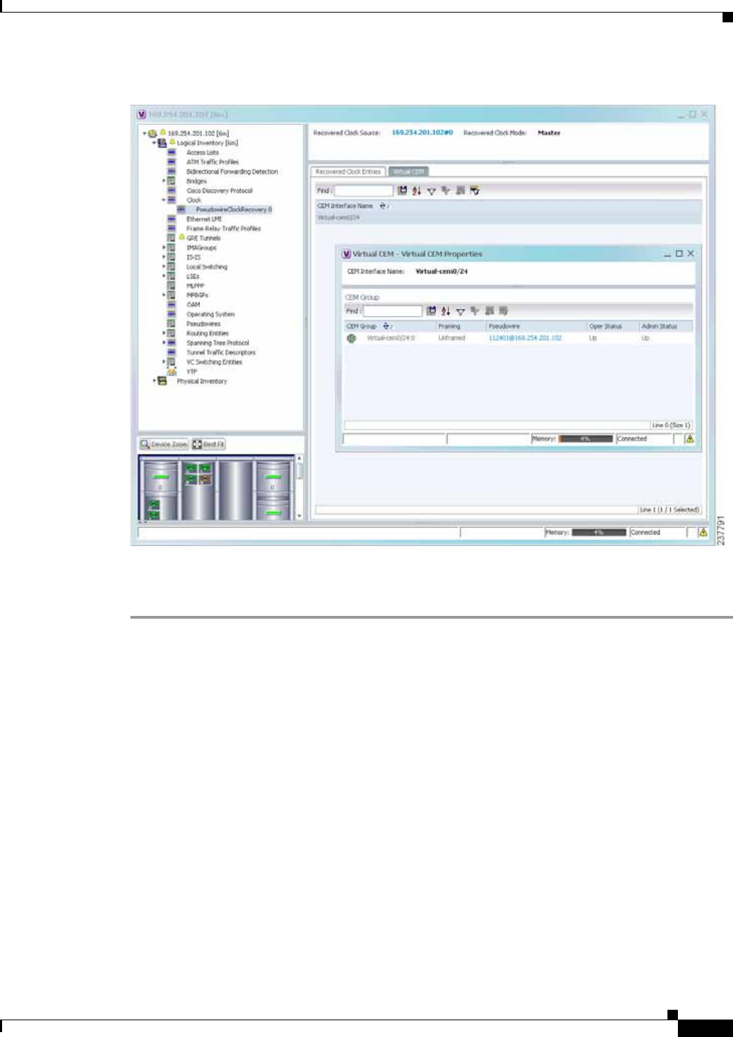
20-53
Cisco Prime Network 4.0 User Guide
OL-29343-01
Chapter 20 Monitoring MToP Services Configuring SONET
Figure 20-28 CEM Group Properties
Step 4 To view additional CEM group properties, double-click the required CEM group.
Table 20-23 describes the information displayed in the CEM Group Properties window.
Configuring SONET
These commands help in configuring the SONET device and in viewing device details.
The table below lists the SONET commands can be launched from the inventory by right-clicking a
SONET port and selecting Commands > SONET. Additional commands may be available for your
devices. New commands are often provided in Prime Network Device Packages, which can be
downloaded from the Prime Network software download site. For more information on how to download
and install DPs and enable new commands, see the information on “Adding Additional Device (VNE)
support” in the Cisco Prime Network 4.0 Administrator Guide.
To run the these commands, the software on the network element must support the technology. Before
executing any commands, you can preview them and view the results. For details on the software
versions Prime Network supports for the listed supported network elements, see Cisco Prime Network
4.0 Supported Cisco VNEs.

20-54
Cisco Prime Network 4.0 User Guide OL-29343-01
Chapter 20 Monitoring MToP Services
Configuring SONET
Note You might be prompted to enter your device access credentials while executing a command. Once you
have entered them, these credentials will be used for every subsequent execution of a command in the
same GUI client session. If you want to change the credentials, click Edit Credentials. The Edit
Credentials button will not be available for SNMP commands or if the command is scheduled for a later
time.
Command Navigation Description
BER Threshold Right-click on SONET port and
select Commands > SONET >
Show >
Performed from command launch point
Controller Data
TCA Threshold
SDH Counters Clear > SONET > N/A; performed from command launch
point
BER Threshold Right-click on SONET port and
select Commands > SONET >
Configure >
BER threshold:
• sf-ber—Sets the signal failure BER
threshold. Value in the range from
3 to 9. The default value is 6
• sd-ber—Sets the signal degrade
BER threshold. Value in the range
from 3 through 9. The default value
is 3
Bit error rate: 3-9, or default. The
default for sf-ber is 3, and the default
for sd-ber is 9.
Line Counters Right-click on SONET port and
select Commands > SONET >
Show > PM
Line type: farendline,
farendline-history, line, or line-history
History interval: 1-96; to view all, enter
0
Medium Counters N/A; performed from command launch
point
Path type: farendpath,
farendpath-history, path, path-history
Path Counters Channelized path index: 1-48 (for a
particular channel) or 0 (for all
channels)
History interval: 1-96; to view all, enter
0
Section Counters Right-click on SONET port and
select Commands > SONET >
Show > PM
Section type: section or section-history
History interval: 1-96; to view all, enter
0
Trace Details Card location (for example, 0/5/CPU0)
Note The device must be managed by
Prime Network with device
admin privileges.

20-55
Cisco Prime Network 4.0 User Guide
OL-29343-01
Chapter 20 Monitoring MToP Services Configuring Clock
Configuring Clock
With Ethernet equipment gradually replacing SONET and SDH equipment in service-provider networks,
frequency synchronization is required to provide high-quality clock synchronization over Ethernet ports.
SyncE and PTP are two widely used clock synchronization protocol used in ethernet based networks.
Clocking configuration commands allows you to configure SyncE and PTP clock configuration on Cisco
router. SyncE and PTP clocking configuration is predominantly used in RAN Backhaul (or MToP)
network where TDM traffic carried from cell site router to central office via packet switched network.
These commands can be launched from the logical inventory by right-clicking on Clock node. Before
executing any commands, you can preview them and view the results.
To run the these commands, the software on the network element must support the technology. Before
executing any commands, you can preview them and view the results. For details on the software
versions Prime Network supports for the listed supported network elements, see Cisco Prime Network
4.0 Supported Cisco VNEs.
Note You might be prompted to enter your device access credentials while executing a command. Once you
have entered them, these credentials will be used for every subsequent execution of a command in the
same GUI client session. If you want to change the credentials, click Edit Credentials. The Edit
Credentials button will not be available for SNMP commands or if the command is scheduled for a later
time.
The table below lists the PTP and SyncE configuration commands. Additional commands may be
available for your devices. New commands are often provided in Prime Network Device Packages,
which can be downloaded from the Prime Network software download site. For more information on
how to download and install DPs and enable new commands, see the information on “Adding Additional
Device (VNE) support” in the Cisco Prime Network 4.0 Administrator Guide.
Clock Source Right-click on SONET port and
select Commands > SONET >
Configure >
Clock source of sent signal on SONET
ports:
• internal—Controller will clock its
sent data using internal clock.
• line—Controller will clock its sent
data using the clock recovered
from the line’s receive data stream.
• default—Cancels any clock source
setting.
TCA Threshold TCA threshold:
• b1-tca—Threshold for B1 BER
TCA, between 3-9 (default is 6).
• b2-tca—Threshold for B2 BER
TCA, between 3-9 (default is 6).
Bit error rate: Value from 3-9 (10 to the
negative x), or default.
Command Navigation Description

20-56
Cisco Prime Network 4.0 User Guide OL-29343-01
Chapter 20 Monitoring MToP Services
Configuring Clock
Command Navigation Description
Create PTP
Clock Global (For ASR 901/903)
Right-click Clock node >
Commands > Configuration >
(For ASR 9000)
Right-click Clock node >
Commands > Configuration >
PTP >
Identify the clock in the network with the
highest priority. The clock with the highest
priority is referred to as the master clock. All
the other devices on the network synchronize
their clocks with the master and are referred to
as members. Constantly exchanged timing
messages between master and members ensure
continued synchronization.
The PTP clock port commands are used to
modify PTP on individual interfaces.
Modify PTP
Clock Global (For ASR 901/903)
Expand Clock node > right-click
PTP Service> Commands >
Configuration >
(For ASR 9000)
Right-click Clock node >
Commands > Configuration >
PTP >
Delete PTP
Clock Global Expand Clock node > right-click
PTP Service> Commands >
Configuration >
Create PTP
Clock Port Expand Clock node > right-click
PTP Service> Commands >
Configuration >
Show PTP
Clock Global Expand Clock node > right-click
PTP Service> Commands >
Show >
Modify PTP
Clock Port
Delete PTP
Clock Port
Expand Clock node > select PTP
node > right-click on the selected
PTP interface > Commands >
Configuration >
Create PTP
Interface
Modify PTP
Interface
Physical
inventory > Chassis > Slot > Sel
ect an interface > Commands >
Configuration > PTP

20-57
Cisco Prime Network 4.0 User Guide
OL-29343-01
Chapter 20 Monitoring MToP Services Configuring TDM and Channelization
Configuring TDM and Channelization
The table below lists the TDM and SONET/SDH channelization configuration commands and navigation
for the commands. These commands can be launched from the physical inventory. Additional commands
may be available for your devices. New commands are often provided in Prime Network Device
Packages, which can be downloaded from the Prime Network software download site. For more
information on how to download and install DPs and enable new commands, see the information on
“Adding Additional Device (VNE) support” in the Cisco Prime Network 4.0 Administrator Guide.
To run the these commands, the software on the network element must support the technology. Before
executing any commands, you can preview them and view the results. For details on the software
versions Prime Network supports for the listed supported network elements, see Cisco Prime Network
4.0 Supported Cisco VNEs.
Create SyncE
Global Right-click Clock node >
Commands > Configuration > Configure clock properties at the global level
such as hold-off time, wait to restore, force
switch, and so on, that helps routers to
synchronize to the best available clock source.
Configure SyncE at the interface level using the
SyncE interface commands.
Modify SyncE
Global (For ASR901, ASR903):
Expand Clock node > right-click
SyncE> Commands >
Configuration >
(For ASR9000):
Right-click Clock node >
Commands > Configuration >
Create SyncE
Interface
Modify SyncE
Interface
(For ASR901, ASR903):
Expand Clock node > right-click
SyncE> Commands >
Configuration >
(For ASR9000):
Physical
inventory > Chassis > Slot > Sel
ect an interface > Commands >
Configuration > SyncE
Create ESMC
Global
Modify ESMC
Global
Expand Clock node > right-click
SyncE> Commands >
Configuration >
Configure ESMC for synchronous Ethernet
(SyncE) clock synchronization.
Only ASR 9003 series router supports the
Synchronization Status Message (SSM) and the
Ethernet Synchronization Message Channel
(ESMC) for synchronous Ethernet (SyncE)
clock synchronization.
Configure ESMC for synchronous Ethernet
(SyncE) clock synchronization on an interface
using the ESMC interface commands.
Create ESMC
Interface
Disable ESMC
Interface
Expand Clock node > select
SyncE > right-click on a SyncE
Interface from the content pane >
Commands > Configuration >
Modify ESMC
Interface
Command Navigation Description

20-58
Cisco Prime Network 4.0 User Guide OL-29343-01
Chapter 20 Monitoring MToP Services
Configuring TDM and Channelization
Note You might be prompted to enter your device access credentials while executing a command. Once you
have entered them, these credentials will be used for every subsequent execution of a command in the
same GUI client session. If you want to change the credentials, click Edit Credentials. The Edit
Credentials button will not be available for SNMP commands or if the command is scheduled for a later
time.
Command Navigation Description
TDM Commands
Configure Card Type Right-click the device >
Commands > Configuration > • For ASR9000, configure the card
type as SONET/SDH an specify the
chassis, slot or the subslot number.
• For ASR 903 and 901, configure
the card type as E1, T1, and specify
the location using slot and bay
number.
Modify E1 Controller
Modify T1 Controller
(For ASR901, ASR903):
Physical Inventory > Chassis
> Slot > right-click on E1 or T1 >
Commands > Configuration >
E1T1 >
or
(For ASR9000, ASR903):
Physical Inventory > Chassis >
Slot > click on SONET >
double-click on a SONET/SDH
High Order Path (HOP) >
right-click LOP > Commands >
Configuration > E1T1 >
• In ASR 9000, E1 and T1 controller
is configured as part of the
channelization, when configuring
the low order path (LOP) for the
SONET controller.
• For ASR 903, you can configure E1
or T1 controller in either of the
following ways:
–
While configuring the card
type
or
–
During the channelization
when configuring the low order
path (LOP) for the SONET.
• For ASR 901, configure the card
type to configure E1 or T1
controller.
Channelization Commands for SONET/SDH
Note Channelization commands also include the TDM commands discussed above. Read the
description to understand the scenario applicable to your device.
Configure Framing
Configure AUG
Mapping
Physical Inventory > Chassis >
Slot > Subslot > right-click on
SONET/SDH-interface >
Commands > Configuration >
SONET >
Configure SDH/SONET framing type
using this command.
Configuring framing as SDH,
configures AU4 by default, but if you
want to change the mode of operation as
AU3, use the AUG Mapping command.

20-59
Cisco Prime Network 4.0 User Guide
OL-29343-01
Chapter 20 Monitoring MToP Services Configuring Automatic Protection Switching (APS )
Configuring Automatic Protection Switching (APS )
APS refers to the mechanism of using a protect interface in the SONET network as the backup for
working interface. When the working interface fails, the protect interface quickly assumes its traffic
load. The working interfaces and their protect interfaces make up an APS group. SONET APS offers
recovery from fiber (external) or equipment (interface and internal) failures at the SONET line layer.
The table below lists the APS configuration commands and navigation for the commands. Additional
commands may be available for your devices. New commands are often provided in Prime Network
Device Packages, which can be downloaded from the Prime Network software download site. For more
information on how to download and install DPs and enable new commands, see the information on
“Adding Additional Device (VNE) support” in the Cisco Prime Network 4.0 Administrator Guide.
To run the these commands, the software on the network element must support the technology. Before
executing any commands, you can preview them and view the results. For details on the software
versions Prime Network supports for the listed supported network elements, see Cisco Prime Network
4.0 Supported Cisco VNEs.
Configure Controller Physical Inventory > Chassis >
Slot > Subslot > right-click on
SONET interface > Commands >
Configuration > SONET >
After configuring SONET/SDH type,
configure the controller using
additional parameters, like specifying
the clock source.
Configure AU3 Physical Inventory > Chassis >
Slot > Subslot > click on SONET-
interface > right-click on a
SONET/SDH HOP > Commands >
Configuration >
Using these commands, you can
configure the parameters for the SDH
channelization.
When you are configuring the
channelized E1/T1 line card for SDH
framing, configure AU-3 or AU-4 as the
mode of operation.
For SDH, both AU-3 and AU-4 AUG
mappings are supported.
Delete AU3
Configure AU4
Delete AU4 If the AUG mapping is configured to be
AU-4, then the following mapping will
be used:
TUG-3 <--> AU-4 <--> AUG
If the mapping is configured to be
AU-3, then the following mapping will
be used:
AU-3 <--> AUG
Configure TUG3
Delete TUG3
Physical Inventory > Chassis >
Slot > Subslot > click on SONET-
interface > double-click on a
SONET/SDH High Order Path
(HOP) > right-click LOP >
Commands > Configuration >
Delete STS
Configure STS
Physical Inventory > Chassis >
Slot > Subslot > click on SONET-
interface > right-click on a
SONET/SDH HOP > Commands >
Configuration >
Using these commands, you can
configure the STS path attributes for the
SONET channelization mode.
Command Navigation Description

20-60
Cisco Prime Network 4.0 User Guide OL-29343-01
Chapter 20 Monitoring MToP Services
Configuring Automatic Protection Switching (APS )
You might be prompted to enter your device access credentials while executing a command. Once you
have entered them, these credentials will be used for every subsequent execution of a command in the
same GUI client session. If you want to change the credentials, click Edit Credentials. The Edit
Credentials button will not be available for SNMP commands or if the command is scheduled for a later
time.
Command Navigation Description
Create APS (For ASR9000):
Right-click on the
device > Commands >
Configuration > APS >
(For ASR903):
Physical Inventory > Chassis >
slot > subslot > SONET interface >
Commands > Configuration >
APS >
Adds an APS group with a specified
number and assign a channel for the
APS group. 0 designates a protect
channel, and 1 designates a working
channel.
Modify APS

CHAPTER
21-1
Cisco Prime Network 4.0 User Guide
OL-29343-01
21
Viewing and Managing SBCs
This chapter identifies and describes the properties for Session Border Controllers (SBCs) that appear
in Cisco Prime Network Vision (Prime Network Vision) logical inventory. It also describes commands
you can run to manage SBCs.
Session Border Controllers (SBCs) control and manage real-time multimedia traffic flows between IP
network borders, handling signaling, and media. SBCs perform native IP interconnection functions
required for real-time communications such as admission control, firewall traversal, accounting,
signaling interworking, and quality-of-service (QoS) management. This includes:
• Protocol and media interworking
• Session routing
• Hosted Network Address Translation (NAT) and firewall traversal
• Security and AAA
• Intra- and inter-VPN interconnections and optimization
• Media transcoding with an external media server
The Cisco Prime Network platform provides fault management, configuration, and performance
monitoring for SBC services. Prime Network SBC commands allow you to configure SBC components.
An SBC consists of combined DBE and SBE functionality:
• Data Border Element (DBE)—Responsible for media-related functions.
• Signaling Border Element (SBE)—Responsible for call signaling-related functions.
In addition, the SBC can operate in the following deployment models:
• Distributed Model (DM)—Contains only the SBE or DBE, resulting in a distributed SBC.
• Unified Model (UM)—Contains both the SBE and DBE, thereby implementing the SBE and DBE
as a single device.
Note The existing Cisco SBC platforms support only DBE.
The following topics describe the SBC properties that are displayed in Prime Network Vision logical
inventory:
• User Roles Required to View SBC Properties, page 21-2
• Viewing SBC Properties in Logical Inventory, page 21-3
• Viewing SBC DBE Properties, page 21-4
• Viewing SBC SBE Properties, page 21-5

21-2
Cisco Prime Network 4.0 User Guide OL-29343-01
Chapter 21 Viewing and Managing SBCs
User Roles Required to View SBC Properties
• Viewing SBC Statistics, page 21-13
• Configuring SBC Components, page 21-14
User Roles Required to View SBC Properties
This topic identifies the GUI default permission or scope security level that is required to view SBC
properties in Prime Network Vision. Prime Network determines whether you are authorized to perform
a task as follows:
• For GUI-based tasks (tasks that do not affect elements), authorization is based on the default
permission that is assigned to your user account.
• For element-based tasks (tasks that do affect elements), authorization is based on the default
permission that is assigned to your account. That is, whether the element is in one of your assigned
scopes and whether you meet the minimum security level for that scope.
For more information on user authorization, see the Cisco Prime Network 4.0 Administrator Guide.
The following tables identify the tasks that you can perform:
• Table 21-1 identifies the tasks that you can perform if a selected element is not in one of your
assigned scopes.
• Table 21-2 identifies the tasks that you can perform if a selected element is in one of your assigned
scopes.
By default, users with the Administrator role have access to all managed elements. To change the
Administrator user scope, see the topic on device scopes in the Cisco Prime Network 4.0 Administrator
Guide.
Table 21-1 Default Permission/Security Level Required for Viewing SBC Properties - Element Not
in User’s Scope
Task Viewer Operator OperatorPlus Configurator Administrator
Viewing SBC properties — — — — X
Using SBC
Configuration and
Monitoring Commands
——— X X
Using SBC Show
Commands ——— X X
Table 21-2 Default Permission/Security Level Required for Viewing SBC Properties - Element in
User’s Scope
Task Viewer Operator OperatorPlus Configurator Administrator
Viewing SBC properties X X X X X
Using SBC
Configuration and
Monitoring Commands
——— X X
Using SBC Show
Commands ——— X X

21-3
Cisco Prime Network 4.0 User Guide
OL-29343-01
Chapter 21 Viewing and Managing SBCs Viewing SBC Properties in Logical Inventory
Viewing SBC Properties in Logical Inventory
To view SBC properties in Prime Network Vision logical inventory, right-click the element configured
for SBC, then choose Inventory > Logical Inventory > Session Border Controller.
The SBC properties are displayed as shown in Figure 21-1.
Figure 21-1 SBC Properties in Logical Inventory
Table 21-3 describes the general SBC properties displayed in logical inventory.
Table 21-3 SBC Properties
Field Description
Process Process name, such as Session Border Controller.
Process Status Status of the process, such as Running.

21-4
Cisco Prime Network 4.0 User Guide OL-29343-01
Chapter 21 Viewing and Managing SBCs
Viewing SBC DBE Properties
Viewing SBC DBE Properties
The DBE controls media packet access to the network, provides differentiated services and QoS for
different media streams, and prevents service theft.
To view SBC DBE properties, choose Logical Inventory > Session Border Controller > DBE.
Table 21-4 describes the DBE properties that appear in logical inventory.
Viewing Media Address Properties
A DBE uses a pool of sequential IPv4 media addresses as local media addresses.
To view SBC media address properties, choose Logical Inventory > Session Border
Controller > DBE > Media Address.
Table 21-5 describes the SBC media address properties that are displayed in logical inventory.
Application Version SBC version number.
Mode Mode in which the SBC is operating:
• Unified
• Distributed DBE
SBC Service Name Name of the service.
Table 21-3 SBC Properties (continued)
Field Description
Table 21-4 SBC DBE Properties
Field Description
Process Process name, such as DBE.
Process Status Status of the process, such as Running.
Name Name assigned to the DBE.
Type Type of DBE, either DBE or virtual DBE (vDBE).
DBE Location Id Unique identifier configured on each vDBE within a UM DBE.
Table 21-5 Media Address Properties
Field Description
Address Range IP addresses defined for the pool.
Port Range Lower Lower end of the port range for the interface. If no range is specified, all possible
Voice over IP (VoIP) port numbers are valid.
Port Range Upper Upper end of the port range for the interface.
VRF Name VRF that the interface is assigned to.
Service Class Class of service (CoS) for each port range, such as fax, signaling, voice, or any.

21-5
Cisco Prime Network 4.0 User Guide
OL-29343-01
Chapter 21 Viewing and Managing SBCs Viewing SBC SBE Properties
Viewing VDBE H.248 Properties
To view VDBE H.248 properties, choose Logical Inventory > Session Border
Controller > DBE > VDBE.
Table 21-6 describes the VDBE H.248 properties that are displayed in logical inventory.
Viewing SBC SBE Properties
The SBE controls the access of VoIP signaling messages to the network core and manipulates the
contents of these messages. It does this by acting as a SIP B2BUA or H.323 gateway.
To view SBC SBE properties, choose Logical Inventory > Session Border Controller > SBE.
Table 21-7 describes the information displayed in logical inventory for an SBE.
Table 21-6 VDBE H.248 Properties
Branch Description
H248 Controller H.248 controller used by the DBE.
The Media Gateway Configuration (MGC) table displays the following
information:
• Index—The number of the H.248 controller. The profile is used to
interoperate with the SBE.
• Remote IP—The remote IP address for the H.248 controller.
• Remote Port—The remote port for the H.248 controller.
• Transport—The transport for communications with the remote device.
H248 Interface The SBC H248 Control Interface table displays the following information:
• IP Address:
–
In DM mode, the local IP address of the DBE used to connect to the
SBE.
–
In UM mode, the local IP address used to connect to the media gateway.
• Port—The port for the H.248 controller interface.
• Transport—The transport the H.248 controller interface uses.
• Association—The relationship between the SBE and the media gateway.
Table 21-7 SBC SBE Properties
Field Description
Process Name of the process, such as SBE.
Process Status Status of the process, such as Running or Idle.
Name Name assigned to this SBE.

21-6
Cisco Prime Network 4.0 User Guide OL-29343-01
Chapter 21 Viewing and Managing SBCs
Viewing SBC SBE Properties
Viewing AAA Properties
For devices that support local and remote billing, the SBC can send billing records to a AAA server using
the RADIUS protocol.
To view AAA properties, choose Logical Inventory > Session Border Controller > SBE > AAA.
Table 21-8 describes the AAA properties that appear in logical inventory for the SBC SBE.
Call Redirect Limit Maximum number of times a call is redirected before the call is declared failed.
The range is 0 to 100 with a default of 2.
On Hold Timeout Amount of time, in milliseconds, that the SBE waits after receiving a media
timeout notification from the DBE for an on-hold call before tearing down the
call.
Table 21-7 SBC SBE Properties (continued)
Field Description
Table 21-8 AAA Properties
Branch Description
AAA Interface The SBE AAA Interface table displays the following information:
• AAA Address—The local AAA interface address.
• Network ID—A unique identifier for the SBE.
Accounting The Accounting Radius Client table displays the following information:
• Name—The name of the accounting client.
• Client Type—The type of client, either Accounting or Authentication.
Authentication The Authentication Radius Client table displays the following information:
• Name—The name of the authentication client.
• Client Type—The type of client, either Accounting or Authentication.
Billing The SBE Billing table displays the following information related to billing:
• LDR Check Time—The time of day (local time) to run the long duration
record check.
• Local Billing Address—The local IP address for SBE billing. This IP
address can be different from the local AAA IP address and is the IP address
written in the bill records.
• Admin Status—The configuration status, available with the running-config
command.
• Operational Status—The running status, available from the CLI. This entry
indicates whether or not the billing interface is up. The status is derived from
the interworking of the SBC and the AAA server.

21-7
Cisco Prime Network 4.0 User Guide
OL-29343-01
Chapter 21 Viewing and Managing SBCs Viewing SBC SBE Properties
Viewing H.248 Properties
The H.248 interface is used for signaling between an SBE and a DBE in distributed mode and between
an SBE and a transcoding media gateway. The SBE or SBC acts as an H.248 MGC, and the transcoding
device acts as an H.248 media gateway. The connection between the MGC and the media gateway is an
H.248 link.
To view H.248 properties, choose Logical Inventory > Session Border Controller > H248.
Table 21-9 describes the H.248 properties that appear in logical inventory for the SBC SBE.
Viewing Policy Properties
An SBC policy is a set of rules that define how the SBC treats different kinds of VoIP events. An SBC
policy allows control of the VoIP signaling and media that pass through the SBC at an application level.
A policy set is a group of policies that can be active on the SBC at any one time. If a policy set is active,
the SBC uses the rules defined within it to apply policy to events. Multiple policies can be set on a single
SBC.
To view policy properties, choose Logical Inventory > Session Border Controller > Policy.
Table 21-10 describes the policy properties that appear in logical inventory for the SBC SBE.
Table 21-9 H.248 Properties
Branch Description
H248 Interface The SBC H248 Control Interface table displays the following information:
• IP Address:
–
In DM mode, the IP address used to connect the DBE and the MGC.
–
In UM mode, the IP address used to connect the SBC and the media
gateway.
• Port—The port for the H.248 controller interface.
• Transport—The transport the H.248 controller interface uses.
• Association—The relationship between the SBE and the media gateway.
Media Gateway The Media Gateway table displays the following information:
• IP Address—The IP address of the media gateway.
• Codec List—A comma-separated list of the codecs supported.

21-8
Cisco Prime Network 4.0 User Guide OL-29343-01
Chapter 21 Viewing and Managing SBCs
Viewing SBC SBE Properties
Table 21-10 Policy Properties
Branch Description
Blacklist The Blacklists table contains the following information:
• Name—The blacklist name.
• Type—The type of source that this blacklist applies to, such as critical or
normal.
CAC Policy A Call Admission Control (CAC) policy is used to define admission control.
The SBE CAC Policy Set table contains the following information:
• Policy Set Number—An identifying number the SBE has assigned to the
policy set.
• First Table—A CAC policy table.
• Status—Whether the policy is active or inactive. If the policy is active, the
SBC applies the defined rules to events.
• First CAC Scope—The scale that the CAC applies for, such as source
adjacency or destination adjacency. This is the first CAC table used for CAC
policy match.
• Description—A brief description of the policy set.
Call Policy A call policy set is used for number analysis and routing.
The SBE Call Policy Set table contains the following information:
• Policy Set Number—An identifying number the SBE has assigned to the
policy set.
• Status—Whether the policy is active or inactive. If the policy is active, the
SBC applies the defined rules to events.
• First Call Table—The first call table used for call policy match.
• Description—A brief description of the policy set.
Codec List The SBE Codec List table contains the following information:
• Name—The name of the codec list.
• Codecs—The codecs contained in each list.

21-9
Cisco Prime Network 4.0 User Guide
OL-29343-01
Chapter 21 Viewing and Managing SBCs Viewing SBC SBE Properties
Current
Blacklisting The Current Blacklistings table contains the following information:
• Type—The type of source this blacklist applies to. Blacklists are used to
block certain VoIP services that meet specified conditions.
• Event Type—The type of event this blacklist applies to, such as
CORRUPT_MESSAGE.
• Is All Source Addresses—Whether the blacklist applies to all source IP
addresses:
–
True—Ignore any IP address in the Source Address field.
–
False—Use the IP address in the Source Address field.
• Source Address—The IP address that this blacklist applies to.
• Source Port Number—The port number that this blacklist applies to.
• Source Port Type—The type of port this blacklist applies to. All is a valid
entry.
• Time Remaining—The amount of time, in hours, minutes, or seconds, before
the blacklist is removed.
Hunting Trigger The hunting trigger enables the SBC to search for other routes or destination
adjacencies if an existing route fails.
The Global Hunting Trigger List table contains the following information:
• Hunting Mode—Indicates the protocol to use to search for routes, such as
Session Initiation Protocol (SIP).
• Hunting Triggers—The SIP responses, such as 468 or 503, that indicate the
SBC is to search for an alternate route or destination adjacency. SIP
responses are defined in RFC3261.
Table 21-10 Policy Properties (continued)
Branch Description

21-10
Cisco Prime Network 4.0 User Guide OL-29343-01
Chapter 21 Viewing and Managing SBCs
Viewing SBC SBE Properties
Viewing SIP Properties
To view SIP properties, choose Logical Inventory > Session Border Controller > SIP.
Table 21-11 describes the SIP entries that appear in logical inventory for the SBC SBE.
QoS Profile QoS profiles can be used by CAC policies and are used exclusively for marking
IP packets.
The QoS Profile table contains the following information:
• Name—The name of the QoS profile.
• Class of Service—The type of call this profile applies to, such as voice,
video, signaling, or fax.
• Marking Type—The type of marking to be applied to the IP packet. Options
include Passthrough, Differentiated Service Code Point (DSCP), and IP
Precedence/ToS.
• IP Precedence—If the marking type is IP Precedence, the specified
precedence, either 0 or 1.
• ToS—If the marking type is ToS, the ToS value.
• DSCP—If the marking type is DSCP, the DSCP value.
SDP The Session Description Protocol (SDP) content pane contains the following
tabs, each with their respective table:
• SBE SDP Policy Table:
–
Instance Name—The name of the policy table.
–
SBE SDP Match Table—The name of the SDP match table.
• SBE SDP Match Table:
–
Instance Name—The name of the SDP match table.
–
Match Strings—The match criteria.
–
Table Type—The type of table, either Blacklist or Whitelist.
Table 21-10 Policy Properties (continued)
Branch Description

21-11
Cisco Prime Network 4.0 User Guide
OL-29343-01
Chapter 21 Viewing and Managing SBCs Viewing SBC SBE Properties
Table 21-11 SIP Properties
Branch Description
SIP Account The SBE Account table contains the following information:
• Name—The name of the account associated with the adjacencies.
• Adjacencies—The identified adjacencies.
SIP Adjacency An adjacency represents a signaling relationship with a remote call agent.
One adjacency is defined per external call agent. Each adjacency belongs
within an account. Each incoming call is matched to an adjacency, and each
outgoing call is routed out over a second adjacency.
The SBC SIP Adjacencies table contains the following information:
• Name—The adjacency name.
• Status—The status of the adjacency, either Attached or Detached.
• Signaling Address—The local IP address and port (optional) for
communications.
• Signaling Peer—The remote IP address and port (optional) for
communications.
• Description—A brief description of the adjacency.
SIP Adjacency Group The Adjacencies Groups table contains the following information:
• Name—The name of the SIP adjacency group.
• Adjacencies—The adjacencies that belong to the group.
SIP Profile The SBC can be configured with whitelist and blacklists profiles on SIP
messages. The following types of SIP profiles are available:
• Header profile—A profile based on SIP header information.
• Method profile—A profile based on SIP method strings.
• Option profile—A profile based on SIP option strings.
• Parameter profile—A profile based on SIP parameters.
SIP Profile >
Header Profile The SIP Header Profiles table contains the following information:
• Name—The name of the SIP header profile.
• Status—Whether or not the profile is in use.
• Profile Type—The type of profile:
–
Whitelist—Accepts SIP requests that match the profile.
–
Blacklist—Rejects SIP requests that match the profile.
• Description—A brief description of the profile.

21-12
Cisco Prime Network 4.0 User Guide OL-29343-01
Chapter 21 Viewing and Managing SBCs
Viewing SBC SBE Properties
SIP Profile >
Method Profile The SIP Method Profiles table contains the following information:
• Name—The name of the SIP method profile.
• Status—Whether or not the profile is in use.
• Profile Type—The type of profile:
–
Whitelist—Accepts SIP requests that match the profile.
–
Blacklist—Rejects SIP requests that match the profile.
• Description—A brief description of the profile.
• Is Passthrough—Whether or not passthrough is enabled:
–
True—Permits message bodies to be passed through for nonvital
methods that match this profile.
–
False—Strips the message body out of any nonvital SIP messages
that match this profile.
SIP Profile >
Option Profile The SIP Option Profiles table contains the following information:
• Name—The name of the SIP option profile.
• Status—Whether or not the profile is in use.
• Profile Type—The type of profile:
–
Whitelist—Accepts SIP requests that match the profile.
–
Blacklist—Rejects SIP requests that match the profile.
• Description—A brief description of the profile.
• Options—The SIP option strings that define this profile, such as host
user-agent, refer redirect, or replaces.
Table 21-11 SIP Properties (continued)
Branch Description

21-13
Cisco Prime Network 4.0 User Guide
OL-29343-01
Chapter 21 Viewing and Managing SBCs Viewing SBC Statistics
Viewing SBC Statistics
The following commands can be launched from the inventory by right-clicking an SBC node and
selecting Commands. The table below lists the SBC configuration commands. Additional commands
may be available for your devices. New commands are often provided in Prime Network Device
Packages, which can be downloaded from the Prime Network software download site. For more
information on how to download and install DPs and enable new commands, see the information on
“Adding Additional Device (VNE) support” in the Cisco Prime Network 4.0 Administrator Guide.
SIP Profile >
Parameter Profile The SIP Parameter Profiles table contains the following information:
• Name—The name of the SIP parameter profile.
• Status—Whether or not the profile is in use.
• Description—A brief description of the profile.
SIP Timer The SBE SIP Timer table contains the following information:
• TCP Connect Timeout—The time, in milliseconds, that the SBC waits
for a SIP TCP connection to a remote peer to complete before failing
that connection. The default is 1000 milliseconds.
• TCP Idle Timeout—The minimum time, in milliseconds, that a TCP
socket does not process any traffic before it closes the connection. The
default is 120000 milliseconds (2 minutes).
• TLS Idle Timeout—The minimum time, in milliseconds, that a
Transport Layer Security (TLS) socket does not process traffic before it
closes the connection.
• Invite Timeout—The time, in seconds, that the SBC waits for a final
response to an outbound SIP invite request. The default is 180 seconds.
If no response is received during that time, an internal request timeout
response is generated and returned to the caller.
• UDP First Retransmit Interval—The time, in milliseconds, that the SBC
waits for a UDP response or ACK before sending the first retransmission
of a signal. The default value is 500 milliseconds.
• UDP Max Retransmit Interval—The maximum time interval, in
milliseconds, for an SBC to retransmit a signal. The maximum
retransmission interval is 4000 milliseconds (4 seconds).
• UDP Response Linger Period—The time, in milliseconds, for which the
SBC retains negative UDP responses to invite requests. The default
value is 32000 milliseconds (32 seconds).
Table 21-11 SIP Properties (continued)
Branch Description

21-14
Cisco Prime Network 4.0 User Guide OL-29343-01
Chapter 21 Viewing and Managing SBCs
Configuring SBC Components
Configuring SBC Components
The following commands can be launched from the logical inventory by right-clicking the Session
Border Controller node. Before executing any commands, you can preview them and view the results. If
desired, you can also schedule the commands.
The table below lists the SBC components configuration commands. Additional commands may be
available for your devices. New commands are often provided in Prime Network Device Packages,
which can be downloaded from the Prime Network software download site. For more information on
how to download and install DPs and enable new commands, see the information on “Adding Additional
Device (VNE) support” in the Cisco Prime Network 4.0 Administrator Guide.
For details on the software versions Prime Network supports for the listed supported network elements,
see Cisco Prime Network 4.0 Supported Cisco VNEs.
Note You might be prompted to enter your device access credentials while executing a command. Once you
have entered them, these credentials will be used for every subsequent execution of a command in the
same GUI client session. If you want to change the credentials, click Edit Credentials. The Edit
Credentials button will not be available for SNMP commands or if the command is scheduled for a later
time.
You can configure the following SBC components using the commands described in this section.
Command Navigation Description
Current 15 Min Statistics Show > PM > Based on the command selected, the
device’s statistics are displayed.
Current 5 Min Statistics
Current Day Statistics
Current Hour Statistics
H.248 Statistics
Previous 15 Minutes Statistics
Previous 5 Minutes Statistics
Previous Day Statistics
Previous Hour Statistics
CPS Data
Media Statistics Show >
Components
Command Navigation Description
SIP Adjancencies

21-15
Cisco Prime Network 4.0 User Guide
OL-29343-01
Chapter 21 Viewing and Managing SBCs Configuring SBC Components
Add SIP Adjacency Right-click the SBC
node > Commands > Add > SIP
Adjacency
Add an SIP adjacency or update an
existing SIP adjacency.
Update SIP Adjacency
Delete SIP Adjacency
In the SIP Adjacencies window,
right-click the adjacency
instance > Commands > Update
/Delete > SIP Adjacency.
Add SIP Adjacency
Outbound AuthRealm
Update SIP Adjacency
Outbound AuthRealm
Delete SIP Adjacency
Outbound AuthRealm
In the SIP Adjacencies window,
right-click the SIP adjacency
instance > Commands > Add /U
pdate/Delete > SIP Adjacency
Outbound AuthRealm.
Use this command to add a SIP
adjacency outbound authentication
realm.
SIP Header Profiles
Add SIP Header Profile Right-click the SBE
node > Commands > Add > SIP
Header Profile
Use the Add SIP Header Profile
command to add a SIP header
profile.
Note When you add a new SIP
header profile, you can add
three headers to it. You can
add more headers to the new
SIP header profile after it is
discovered.
Update SIP Header Profile
Delete SIP Header Profile
In the SIP Header Profiles
window, right-click the
profile > Commands > Update/D
elete > SIP Header Profile
Add SIP Header Profile
Header In the SIP Header Profiles
window, right-click the SIP header
profile
instance > Commands > Add
> SIP Header Profile Header
Use the Add Header command to
add a header to an existing header
profile
Delete SIP Header Profile
Header In the header profile properties
window, right-click the header you
want to remove and
choose > Commands > Delete >
SIP Header Profile Header
Delete a header from a header
profile.
Add SIP Header Profile
Entry Right-click the SBE
node > Commands > Add > SIP
Header Profile Entry
Use this command to add an entry to
an existing SIP header profile
header.
Update SIP Header Profile
Entry
Delete SIP Header Profile
Entry
Right-click an entry in the SIP
Header Profile Header Properties
window > Commands
> Update/Delete > SIP Header
Profile Entry
Update or deletean existing SIP
Header Profile entry in the SIP
Header Profile Header Properties
window.
Command Navigation Description

21-16
Cisco Prime Network 4.0 User Guide OL-29343-01
Chapter 21 Viewing and Managing SBCs
Configuring SBC Components
Add SIP Header Profile
Condition Expand the SBE node, SIP node,
and SIP Profile node, and click the
Header Profile
node > double-click a header
profile to open the SIP Header
Profile Properties window
> Double-click a header
> Right-click an
entry > Commands > Add > SIP
Header Profile Condition
Use this command to add a
condition to a SIP header profile
header.
SIP Option Profiles
Add SIP Option Profile Right-click the SBE
node > Commands > Add > SIP
Option Profile
Configure SIP option profile
paramters such as option profile
type (whitelist or blacklist), profile
options, and so on.
Update SIP Option Profile
Delete SIP Option Profile
Right-click a profile in the SIP
Option Profile
window > Commands
> Update/Delete > SIP Option
Profile
Add SIP Parameter
Profile Right-click the SBE
node > Commands > Add > SIP
Parameter Profile
Configure SIP parameter profile.
Delete SIP Parameter
Profile Click the Parameter Profile node,
right-click the
profile > Commands > Delete >
SIP Parameter Profile
Add SIP Parameter
Profile Parameter Expand the SBE node, SIP node,
SIP Profile node > click the
Parameter Profile > right-click
the profile instance > Commands
> Add > SIP Parameter Profile
Parameter
Add, update, or delete parameter in
SIP parameter profiles.
Specify the parameter name to be
updated and the name of the profile
in which you want to add or update
the parameter.
Update SIP Parameter
Profile Parameter
Delete SIP Parameter
Profile Parameter
Double-click the profile that
contains the
parameter > right-click the
parameter > Commands >
Update/Delete > SIP Parameter
Profile Parameter
Blacklists
Add Blacklist Right-click
the SBE node > Commands > Ad
d > Blacklist
Add or delete blacklist in the SBC
node. Specify the IP address, port
type, and the port number to be
blacklisted.
Delete Blacklist In the Configured Blacklist
Properties window, right-click
the blacklist > Commands > Del
ete > Blacklist
Command Navigation Description

21-17
Cisco Prime Network 4.0 User Guide
OL-29343-01
Chapter 21 Viewing and Managing SBCs Configuring SBC Components
Add Blacklist Reason Right-click the blacklist
instance > Commands > Add
> Blacklist Reason
Add, modify, or delete a blacklist
reason for the blacklisted node in
SBC.
Update Blacklist Reason
Delete Blacklist Reason
In the Configured Blacklist
Properties window, right-click a
blacklist
reason > Commands > Update/
Delete > Blacklist Reason
Call Admission Control (CAC) Policies
Add CAC Policy Set Right-click the SBE
node > Commands > Add > CA
C Policy Set
Add, modify, or delete a CAC
Policy Set
Update CAC Policy Set
Delete CAC Policy Set
In the CAC Policy Set window,
right-click the policy set
instance > Commands
> Update/Delete > CAC Policy
Set
Add CAC Policy Table In the CAC Policy Set window,
right-click the CAC policy
instance > Commands > Add >
CAC Policy Table
Add or modify a CAC policy table
in an existing CAC policy set.
Update CAC Policy Table
Delete CAC Policy Table
Right-click a policy table in the
CAC Policy Set Properties
window > Commands > Update/
Delete > CAC Policy Table
Add CAC Rule Entry Right-click a policy
table > Commands > Add > CA
C Rule Entry
Add or modify a CAC rule entry in
an existing CAC policy table.
Update CAC Rule Entry
Delete CAC Rule Entry
Right-click an entry in the CAC
Rule Entry
tab > Commands > Update/Dele
te > CAC Rule Entry
Add Call Policy Set Right-click the SBE
node > Commands > Add > Call
Policy Set
Add, modify, or delete a Call Policy
Set.
Note When you add a new call
policy set, you can add three
call policy tables. You can
add more tables after the
call policy set you created is
discovered.
Update Call Policy Set
Delete Call Policy Set
Right-click a policy set in the Call
Policy Set
window > Commands > Update
> Call Policy Set
Command Navigation Description

21-18
Cisco Prime Network 4.0 User Guide OL-29343-01
Chapter 21 Viewing and Managing SBCs
Configuring SBC Components
Add Call Policy Table In the Call Policy Set window,
right-click the policy
set > Commands > Add > Call
Policy Table
Add, modify, or delete call policy
tables
Update Call Policy Table
Delete Call Policy Table
Double-click a policy set, then
right-click a policy
table > Commands > Update
> Call Policy Table
Add Call Rule Entry Right-click a policy
table > Commands > Add >
Call Rule Entry
Add, modify, or delete an entry from
an existing call policy table.
Update Call Rule Entry
Delete Call Rule Entry
Double-click a policy table, then
right-click an
entry > Commands > Update/De
lete > Call Rule Entry
Codec Lists
Add Codec List Right-click the SBE
node > Commands > Add > Cod
ec List
Add, or delete a Codec List
Delete Codec List In the Codec List window,
right-click a list
instance > Commands > Delete
> Codec List
Add Codec List Entry In the Codec List window,
right-click the codec list
instance > Commands > Add >
Codec List Entry
Add, modify, or delete an entry in a
codec list.
Update Codec List Entry
Delete Codec List Entry
Double-click the codec list, then
right-click the
codec > Commands > Update /D
elete> Codec List Entry
Media Addresses
Add Media Address Right-click the SBE
node > Commands > Add > Med
ia Address
Add a media address or media
Address DBE with parameters
indicating that media address is
managed by the Data Border
Element (DBE) or Media Gateway
Configuration (MGC).
Add Media Address Dbe Right-click the DBE
node > Commands > Add > Med
ia Address Dbe
Delete Media Address Expand the DBE node and click
the Media Address
node > right-click the media
address > Commands > Delete >
Media Address
Delete an existing media address
from the DBE node.
QoS Profiles
Command Navigation Description

21-19
Cisco Prime Network 4.0 User Guide
OL-29343-01
Chapter 21 Viewing and Managing SBCs Configuring SBC Components
Add QoS Profile Right-click the SBE
node > Commands > Add > QoS
Profile
Configure QoS profile on a SBE
node
Update QoS Profile
Delete QoS Profile
Right-click the profile in the QoS
Profile window
> Commands > Update > QoS
Profile
Command Navigation Description

21-20
Cisco Prime Network 4.0 User Guide OL-29343-01
Chapter 21 Viewing and Managing SBCs
Configuring SBC Components

CHAPTER
22-1
Cisco Prime Network 4.0 User Guide
OL-29343-01
22
Monitoring AAA Configurations
AAA refers to Authentication, Authorization, and Accounting, which is a security architecture for
distributed systems that determines the access given to users for specific services and the amount of
resources they have used.
• Authentication—This method identifies users, including their login and password, challenge and
response, messaging support, and encryption. Authentication is the way to identify a subscriber
before providing access to the network and network services.
• Authorization—This method provides access control, including authorization for a subscriber or
domain profile. AAA authorization sends a set of attributes to the service describing the services
that the user can access. These attributes determine the user’s actual capabilities and restrictions.
• Accounting—This method collects and sends subscriber usage and access information used for
billing, auditing, and reporting. For example, user identities, start and stop times, performed actions,
number of packets, and number of bytes. Accounting enables an operator to analyze the services that
the users access as well as the amount of network resources they consume. Accounting records
comprise accounting Attribute Value Pairs (AVPs) and are stored on the accounting server. This
accounting information can then be analyzed for network management, client billing, and/or
auditing.
This chapter contains the following topics:
• Supported Network Protocols, page 22-1
• Viewing AAA Configurations in Prime Network Vision, page 22-2
• Configuring AAA Groups, page 22-12
Supported Network Protocols
AAA supports the following protocols:
• Diameter—This is a networking protocol that provides centralized AAA management for devices to
connect and use a network service, and an alternative to RADIUS. Diameter Applications can extend
the base protocol, by adding new commands and/or attributes.
• Remote Authentication Dial In User Service (RADIUS)—This is a networking protocol that
provides centralized AAA management for devices to connect and use a network service. RADIUS
is a client/server protocol that runs in the application layer, using UDP as transport. The Remote
Access Server (RAS), the Virtual Private Network (VPN) server, the network switch with port-based
authentication, and the Network Access Server (NAS), are all gateways that control access to the
network, and all have a RADIUS client component that communicates with the RADIUS server.

22-2
Cisco Prime Network 4.0 User Guide OL-29343-01
Chapter 22 Monitoring AAA Configurations
Viewing AAA Configurations in Prime Network Vision
Viewing AAA Configurations in Prime Network Vision
Prime Network allows you to view the AAA configurations for Cisco ASR9000 and Cisco ASR5000
series network elements.
This topic contains the following sections:
• Viewing AAA Group Profile, page 22-2
• Viewing Dynamic Authorization Profile, page 22-3
• Viewing Radius Global Configuration Details, page 22-4
• Viewing AAA Group Configuration Details, page 22-5
Viewing AAA Group Profile
To view the AAA group profile:
Step 1 Right-click on the required device and choose the Inventory option.
Step 2 In the Inventory window, choose Logical Inventory > AAA. The AAA attribute details are displayed in
the content pane.
Note These attributes are available only for Cisco ASR 9000 series network elements.
Table 22-1 describes the fields that are displayed in the content pane.
Step 3 In the Inventory window, choose AAA group node under the AAA node.
Step 4 Under the AAA group node, select and expand the required group and choose the Radius
Configuration option. The group details are displayed in the content pane.
Table 22-2 describes the fields that are displayed in the Radius Configuration dialog box.
Table 22-1 AAA Attributes
Field Name Description
Type Customization applied to the attribute.
Key Unique format name applied to the attribute.
Value Formatting applied to the attribute.

22-3
Cisco Prime Network 4.0 User Guide
OL-29343-01
Chapter 22 Monitoring AAA Configurations Viewing AAA Configurations in Prime Network Vision
Viewing Dynamic Authorization Profile
To view the dynamic authorization profile:
Step 1 Right-click on the required device and choose the Inventory option.
Step 2 In the Inventory window, choose Logical Inventory > AAA > Dynamic Authorization. The
authorization details are displayed in the content pane. You can click on the tabs to view more details.
Note These attributes are available only for Cisco ASR 9000 series network elements.
Table 22-3 describes the fields that are displayed in the Dynamic authorization content pane.
Table 22-2 Radius Configuration Details
Field Name Description
Load Balancing Method The load balancing method.
Ignore Preferred Server Indicates if a transaction associated with a single AAA session should
attempt to use the same server or not.
VRF Virtual routing and forwarding (VRF) associated with the AAA group.
Click the hyperlink to view the relevant node under the VRF node in the
logical inventory.
Dead Time The deadtime for the profile.
Table 22-3 Dynamic Authorization Details
Field Name Description
Protocol The name of the protocol.
Server Listen Port The port number that receives service requests.
Ignore Server Key Indicates whether the server key must be ignored. Values are:
• true
• false
CoA Clients Tab
IP Address The IP address of the Change of Authorization (CoA) client.
VRF The associated VRF to which the CoA client belongs. Click the
hyperlink to view the relevant node under the VRF node.

22-4
Cisco Prime Network 4.0 User Guide OL-29343-01
Chapter 22 Monitoring AAA Configurations
Viewing AAA Configurations in Prime Network Vision
Viewing Radius Global Configuration Details
To view the radius global configuration details:
Step 1 Right-click on the required device and choose the Inventory option.
Step 2 In the Inventory window, choose Logical Inventory > AAA > Radius Global Configuration. The
authorization details are displayed in the content pane.
Note These attributes are available only for Cisco ASR 9000 series network elements.
Table 22-4 describes the fields that are displayed in the Radius global configuration content pane.
Table 22-4 Radius Global Configuration Details
Field Name Description
Load Balancing Method The load balancing method using which the next host is selected. The
server with the least transactions outstanding is generally picked as the
next host.
Ignored Preferred
Server Indicates if a transaction associated with a single AAA session should
attempt to use the same server or not.
Request Timeout The request timeout value for the device.
Dead Time The amount of time (in minutes) after which the dead RADIUS server
will be treated as active.
Retransmit Indicates whether retransmission of data is allowed.
Retransmit Count The retransmission count.
Dead Criteria Time The time interval after which the device is considered unavailable.
Dead Criteria
Retransmit Count The retransmission count after the dead criteria time.
Accounting Servers/ Authentication Servers
Server IP The IP address of the server.
Server Port The server port.
Preference The preferred server.
Operational State The current operational state of the interface.
Administrative Status The administrative status of the interface.
Retain Administrative
Status After Reboot Indicates whether the administrative status must be retained after the
system reboots.
Keepalive
Representative Group The keepalive representative group.
Request Timeout The request timeout value for the device.
Retransmit Count The retransmission count.
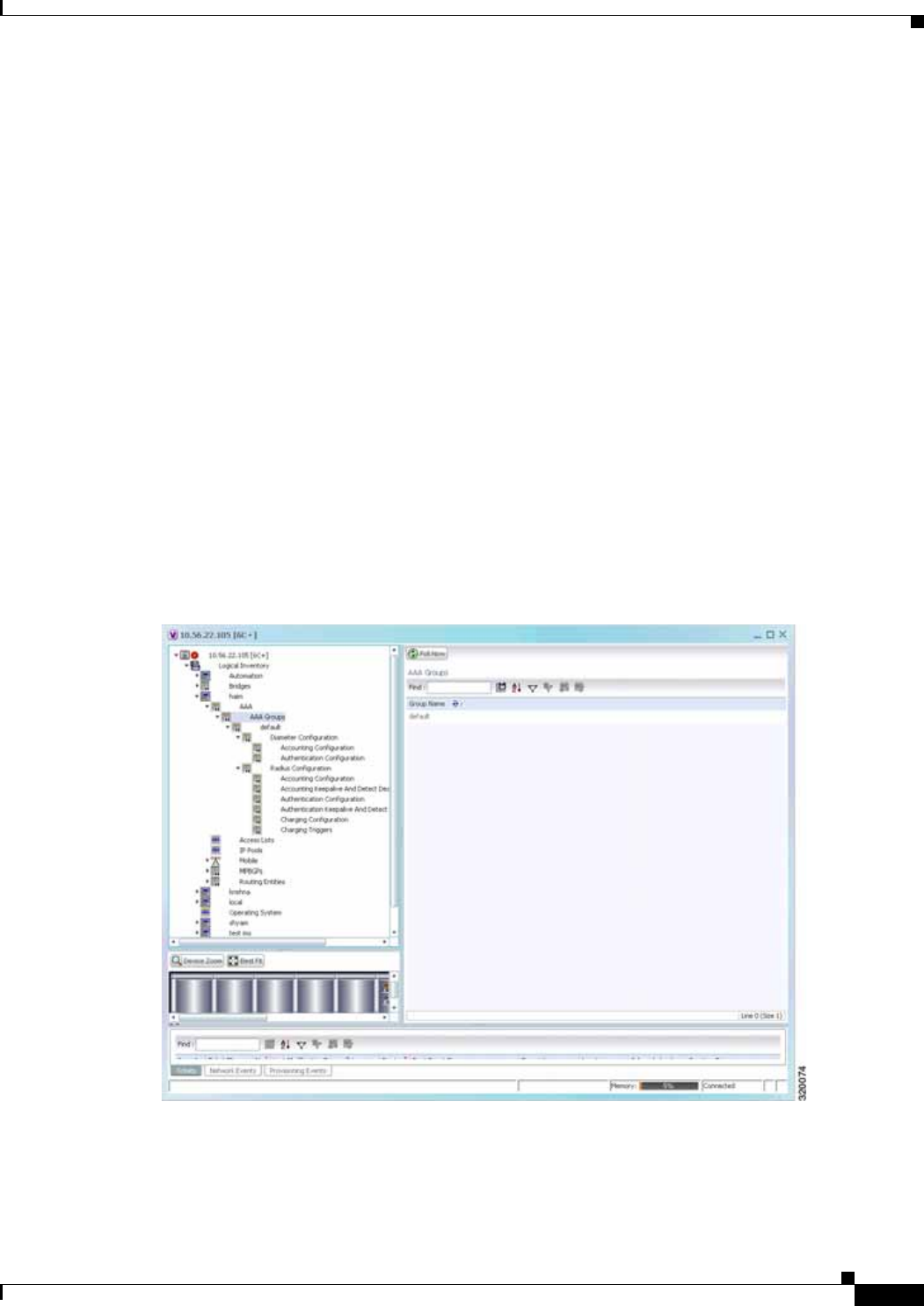
22-5
Cisco Prime Network 4.0 User Guide
OL-29343-01
Chapter 22 Monitoring AAA Configurations Viewing AAA Configurations in Prime Network Vision
Viewing AAA Group Configuration Details
For a Cisco ASR5000 device, Prime Network Vision allows you to view the following configurations for
an AAA group:
• Diameter Configuration
–
Accounting Configuration
–
Authentication Configuration
• Radius Configuration
–
Accounting Configuration
–
Accounting Keepalive and Detect Dead Server Configuration
–
Authentication Configuration
–
Authentication Keepalive and Detect Dead Server Configuration
–
Charging Configuration
–
Charging Triggers
Prime Network Vision displays the AAA configuration details under the AAA container as shown in
Figure 22-1. You can view the individual AAA group details by choosing Logical
Inventory > Context > AAA > AAA Groups.
Figure 22-1 AAA Groups in Logical Inventory

22-6
Cisco Prime Network 4.0 User Guide OL-29343-01
Chapter 22 Monitoring AAA Configurations
Viewing AAA Configurations in Prime Network Vision
Viewing Diameter Configuration Details for an AAA Group
To view the diameter configuration details for a AAA group:
Step 1 Right-click on the required device and choose the Inventory option.
Step 2 In the Inventory window, choose Logical Inventory > Context > AAA > AAA Groups.
You can view the AAA groups on the content pane.
Step 3 Choose Diameter Configuration under a specific AAA group node. The diameter configurations made
for accounting servers and authentication servers are displayed in the respective tabs on the content pane.
Click on the tabs to view more details.
Table 22-5 describes the diameter configuration details for accounting and authentication servers.
Step 4 In the Inventory window, choose Accounting Configuration or Authentication Configuration under
the Diameter Configuration node. The configuration details are displayed on the content pane.
Table 22-6 describes the accounting/authentication diameter configuration details.
Table 22-5 Diameter Configuration
Field Name Description
Accounting Servers/Authentication Servers
Server Host Host name of the diameter authentication/accounting server.
Priority Relative priority of the diameter authentication/accounting server.
Number of Instances in
Up State Number of instances between the diameter authentication/accounting
server and the AAA manager that are in UP status.
Number of Instances in
Down State Number of instances between the diameter authentication/accounting
server and the AAA manager that are in DOWN status.
Table 22-6 Accounting/Authentication Diameter Configuration
Field Name Description
Dictionary Diameter dictionary used for accounting/authentication.
Endpoint Name Diameter endpoint used for accounting/authentication.
Maximum
Transmissions Maximum number of transmission attempts for diameter
accounting/authentication.
Maximum Retries Number of retry attempts for diameter accounting/authentication
requests.
Request Timeout Diameter accounting/authentication request timeout period.
Redirect Host AVP Indicates whether to use:
• one returned AVP
• the first returned AVP as the primary host and the second returned
AVP as the secondary host.
This field is applicable only for Authentication configuration.

22-7
Cisco Prime Network 4.0 User Guide
OL-29343-01
Chapter 22 Monitoring AAA Configurations Viewing AAA Configurations in Prime Network Vision
Viewing Radius Configuration Details for an AAA Group
To view the radius configuration details for an AAA group:
Step 1 Right-click on the required device and choose the Inventory option.
Step 2 In the Inventory window, choose Logical Inventory > Context > AAA > AAA Groups > AAA
Group > Radius Configuration. The configurations made for accounting, authentication, charging, and
charging accounting servers are displayed in the respective tabs on the content pane. Click on the tabs
to view more details.
Table 22-7 describes the radius configuration details for accounting, authentication, charging, and
charging accounting servers.
Viewing Radius Accounting Configuration Details for an AAA Group
To view the radius accounting configuration details for an AAA group:
Step 1 Right-click on the required device and choose the Inventory option.
Step 2 In the Inventory window, choose Logical Inventory > Context > AAA > AAA Groups > AAA
Group > Radius Configuration > Accounting Configuration. The accounting configuration details
are displayed in the content pane.
Table 22-7 Radius Configuration
Field Name Description
Dictionary The radius dictionary.
Strip Domain Indicates whether the domain must be stripped from the user name prior
to authentication or accounting.
Authenticator
Validation Indicates whether the MD5 authentication of the user is enabled or
disabled.
Allow Server Down
Authentication Indicates whether subscriber sessions are allowed when RADIUS
authentication is unavailable.
Allow Server Down
Accounting Indicates whether subscriber sessions are allowed when RADIUS
accounting is unavailable.
Accounting Servers/Authentication Servers/Charging Servers/Charging Accounting Servers
Server Name IP address of the RADIUS server.
Server Port Port used to communicate with the RADIUS server.
Preference Preference of the RADIUS server.
Operational State Status of the RADIUS server.
Administrative Status Administrative status of the RADIUS server.
Retain Administrative
Status after Reboot Indicates whether the administrative status must be retained when the
system reboots.
Keepalive
Representative Group Name of the Keepalive representative group.

22-8
Cisco Prime Network 4.0 User Guide OL-29343-01
Chapter 22 Monitoring AAA Configurations
Viewing AAA Configurations in Prime Network Vision
Table 22-8 describes the radius accounting configuration details.
Table 22-8 Radius Accounting Configuration
Field Name Description
Server Selection
Algorithm The algorithm to select the RADIUS accounting server(s) to which
accounting data must be sent. Values are:
• first-n n Default
• first-server
• round-robin
Billing Version The billing system version of RADIUS accounting servers.
Server Deadtime The number of minutes after which communication must be attempted
with a server that is not reachable.
Maximum Outstanding
Messages The maximum number of outstanding messages that can be queued with
the AAA manager.
Fire and Forget Indicates whether RADIUS Fire-and-Forget accounting is enabled for
the AAA group.
Maximum
Transmissions The maximum number of transmissions attempted for a RADIUS
accounting message, before it is declared FAILED.
Maximum Retries The maximum number of attempts with the AAA server, before it is
declared Not Responding and the detect dead server’s consecutive
failures count is incremented.
Maximum PDU Size
(Bytes) The maximum packed data unit size, in bytes, that can be accepted or
generated.
Response Timeout The time period, in seconds, to wait for a response from the RADIUS
server, before resending the message.
Remote Address Indicates whether the remote IP address lists are configured and the
collection of accounting data for the addresses in these lists are enabled.
Archive Messages Indicates whether archiving of the RADIUS accounting messages in the
system (after retries to all available RADIUS accounting servers) is
enabled.
APN To Be Included The Access Point Name (APN) associated with the RADIUS
accounting.
Interim Interval The time interval (in seconds) between sending interim accounting
records.
GTP Trigger Policy The downlink volume that triggers interim RADIUS accounting.

22-9
Cisco Prime Network 4.0 User Guide
OL-29343-01
Chapter 22 Monitoring AAA Configurations Viewing AAA Configurations in Prime Network Vision
Viewing the Radius Keepalive and Detect Dead Server Configuration Details for an AAA Group
To view the radius accounting/authentication Keepalive and Detect Dead Server Configuration details:
Step 1 Right-click on the required device and choose the Inventory option.
Step 2 In the Inventory window, choose Logical Inventory > Context > AAA > AAA Groups > AAA
Group > Radius Configuration > Accounting Keepalive and Detect Dead Server Configuration or
Authentication Keepalive and Detect Dead Server Configuration. The configuration details are
displayed in the content pane.
Table 22-9 describes the radius accounting keepalive and detect dead server configuration details.
Viewing the Radius Authentication Configuration Details for an AAA Group
To view the radius authentication configuration details for an AAA group:
Step 1 Right-click on the required device and choose the Inventory option.
Step 2 In the Inventory window, choose Logical Inventory > Context > AAA > AAA Groups > AAA
Group > Radius Configuration > Authentication Configuration. The authentication configuration
details are displayed in the content pane.
Table 22-10 describes the radius authentication configuration details.
Table 22-9 Radius Accounting Keepalive and Detect Dead Server Configuration details
Field Name Description
Keepalive Interval The time interval (in seconds) between two keepalive access requests.
Keepalive Timeout The time period to wait for a response from the RADIUS server, before
resending the message. This value is displayed in seconds.
KeepAlive Maximum
Retries The maximum number of keepalive access requests to be sent, before the
server is declared as not reachable.
Keepalive Consecutive
Response The number of consecutive accounting responses after which the server
is declared as reachable.
Username The accounting user name.
Calling Station ID The calling station ID to be used for keepalive accounting.
Keepalive Password The password to be used for authentication. This field is available only
for authentication configuration.
Keepalive Allow Access
Reject Indicates the valid response for authentication request. This field is
available only for authentication configuration.
Detect Dead Server
Consecutive Failures The number of consecutive failures for an AAA manager, before the
status of an accounting server is changed from Active to Down.
Detect Dead Server
KeepAlive The number of seconds to wait for a response to any message, before the
status of an accounting server is changed from Active to Down.

22-10
Cisco Prime Network 4.0 User Guide OL-29343-01
Chapter 22 Monitoring AAA Configurations
Viewing AAA Configurations in Prime Network Vision
Viewing the Charging Configuration Details for an AAA Group
To view the radius charging configuration details for an AAA group:
Step 1 Right-click on the required device and choose the Inventory option.
Step 2 In the Inventory window, choose Logical Inventory > AAA > AAA Groups > AAA Group > Radius
Configuration > Charging Configuration. The charging configuration details are displayed in the
content pane.
Table 22-11 describes the charging configuration details.
Table 22-10 Radius Authentication Configuration
Field Name Description
Server Selection
Algorithm The algorithm to select the RADIUS accounting server(s) to which
accounting data must be sent. Values are:
• first-server
• round-robin
Server Deadtime The time period after which the status of the authentication server must
be changed from Down to Active.
Maximum Outstanding
Messages The maximum number of outstanding messages that can be queued with
the AAA manager.
Authentication
Maximum Retries The maximum number of attempts with the AAA server, before it is
declared Not Responding and the detect dead server’s consecutive
failures count is incremented.
Authentication
Maximum
Transmissions
The maximum number of transmissions attempted for a RADIUS
authentication message, before it is declared FAILED.
Authentication
Response Timeout The time period to wait for a response from the RADIUS server, before
resending the message. This value is displayed in seconds.
APN To Be Included The APN associated with the RADIUS authentication.
Authenticate Null User
Name Indicates whether the authentication of user names that are blank or
empty is enabled.
Modify NAS IP Indicates whether the RADIUS authentication is attempted after NAS IP
is modified.
Probe Interval The time interval (in seconds) before sending another probe
authentication request to a RADIUS server.
Probe Timeout The time period (in seconds) to wait for a response from a RADIUS
server before resending the authentication probe.
Probe Maximum
Retries The number of retries for RADIUS authentication probe response before
the authentication is declared as failed.

22-11
Cisco Prime Network 4.0 User Guide
OL-29343-01
Chapter 22 Monitoring AAA Configurations Viewing AAA Configurations in Prime Network Vision
Viewing the Charging Trigger Configuration Details for an AAA Group
To view the radius charging trigger configuration details for an AAA group:
Step 1 Right-click on the required device and choose the Inventory option.
Step 2 In the Inventory window, choose Logical Inventory > Context > AAA > AAA Groups > AAA
Group > Radius Configuration > Charging Trigger. The charging configuration details are displayed
in the content pane.
Table 22-12 describes the charging trigger configuration details.
Table 22-11 Radius Charging Configuration
Field Name Description
Authentication Server
Selection Algorithm The algorithm to select the RADIUS server(s) for active charging
service to ensure proper load distribution amongst the available servers
used for authentication requests. Value could be one of the following:
• first-server
• round-robin
Accounting Server
Selection Algorithm The algorithm to select the RADIUS server(s) for active charging
service to ensure proper load distribution amongst the available servers
for accounting requests. Value could be one of the following:
• first-n n Default
• first-server
• round-robin
Server Deadtime The time period after which the status of the RADIUS server must be
changed from Down to Active.
Maximum Outstanding
Messages The maximum number of outstanding messages that can be queued with
the AAA manager.
Maximum Retries The maximum number of attempts with the AAA server, before it is
declared Not Responding and the detect dead server’s consecutive
failures count is incremented.
Response Timeout The maximum number of retransmissions for RADIUS authentication
requests.
Detect Dead Server
Consecutive Retries The number of consecutive failures for an AAA manager, before the
status of an charging server is changed from Active to Down.

22-12
Cisco Prime Network 4.0 User Guide OL-29343-01
Chapter 22 Monitoring AAA Configurations
Configuring AAA Groups
Configuring AAA Groups
The following commands can be launched from the inventory by choosing AAA
Group > Commands > Configuration.
The table below lists AAA Group configuration commands. Additional commands may be available for
your devices. New commands are often provided in Prime Network Device Packages, which can be
downloaded from the Prime Network software download site. For more information on how to download
and install DPs and enable new commands, see the information on “Adding Additional Device (VNE)
support” in the Cisco Prime Network 4.0 Administrator Guide.
Before executing any commands, you can preview them and view the results. If desired, you can also
schedule the commands. To find out if a device supports these commands, see the Cisco Prime Network
4.0 Supported Cisco VNEs.
Note You might be prompted to enter your device access credentials while executing a command. Once you
have entered them, these credentials will be used for every subsequent execution of a command in the
same GUI client session. If you want to change the credentials, click Edit Credentials. The Edit
Credentials button will not be available for SNMP commands or if the command is scheduled for a later
time.
Table 22-12 Radius Charging Triggers Configuration
Field Name Description
Serving Node Change Indicates whether RADIUS trigger for serving node is enabled.
Radio Access
Technology Change Indicates whether RADIUS trigger for radio access technology change
is enabled.
User Location
Information Change Indicates whether RADIUS trigger for user location information change
is enabled.
Routing Area
Information Change Indicates whether RADIUS trigger for routing area information change
is enabled.
Quality of Service
Change Indicates whether RADIUS trigger for quality of service change is
enabled.
Mobile Station
Timezone Change Indicates whether RADIUS trigger for mobile station time zone change
is enabled.

22-13
Cisco Prime Network 4.0 User Guide
OL-29343-01
Chapter 22 Monitoring AAA Configurations Configuring AAA Groups
Command Navigation Description
Create Diameter
Accounting Server Right-click on AAA
group > Commands >
Configuration
Use this command to create a new diameter
accounting server.
Create Diameter
Authentication Server Use this command to create a new diameter
authentication server.
Delete AAA Group Use this command to delete an AAA group.
Modify AAA Group Use this command to modify the attributes of
an AAA group.

22-14
Cisco Prime Network 4.0 User Guide OL-29343-01
Chapter 22 Monitoring AAA Configurations
Configuring AAA Groups

CHAPTER
23-1
Cisco Prime Network 4.0 User Guide
OL-29343-01
23
Monitoring IP Pools
An IP pool is a sequential range of IP addresses within a certain network. We can have multiple pool
configurations. Each pool can have a priority and can be assigned to a group.
IP addresses can be assigned dynamically from a single pool or from a group of pools. The Least
Recently Used (LRU) method is used to assign IP addresses. In each pool, the addresses are placed in a
queue. At the time of assigning, the address at the head of the queue is assigned, and when released is
placed at the end of the queue.
When a group of pools have the same priority, an algorithm is used to determine a probability for each
pool based on the number of available addresses. A pool is selected based on the probability determined.
This method allocates addresses evenly from the group of pools.
IP pool supports both IPv4 and IPv6 addresses. With the IP Pool feature, Prime Network provides the
flexibility of assigning IP addresses dynamically for services running on a network element. A service
running on a network element can refer to an appropriate IP pool and an IP address gets assigned to the
service from the IP pool.
This chapter contains the following topics:
• Viewing the IP Pool Properties, page 23-1
• Modifying and Deleting IP Pools, page 23-3
Viewing the IP Pool Properties
To view the IP pool properties for a device:
Step 1 In Prime Network Vision, right-click the required device, and choose Inventory.
Step 2 In the Inventory window, choose Logical Inventory > Context > IP Pools. A list of IP pools are
displayed in the content pane.
Table 23-1 describes the fields that are displayed in the content pane.
Table 23-1 IP Pool Properties
Field Name Description
Table Types Displays the type of table, which is IP Pools.
IP Pools
Name Name of the IP pool.
IP Pool Entries Indicates whether entries exist for this pool.
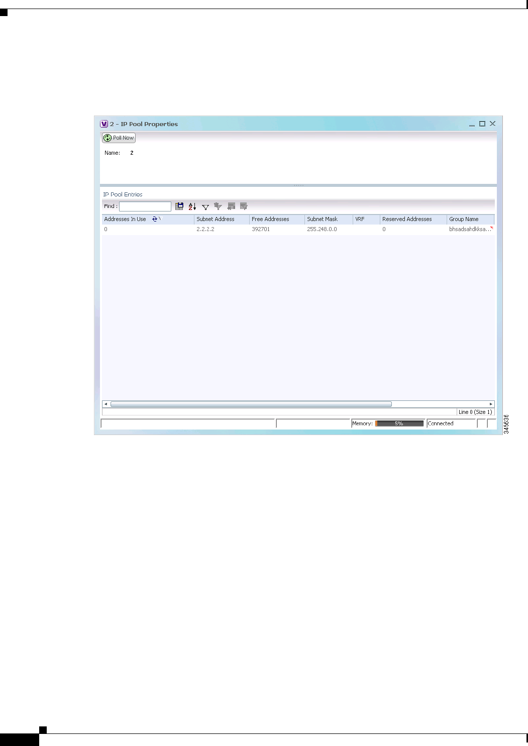
23-2
Cisco Prime Network 4.0 User Guide OL-29343-01
Chapter 23 Monitoring IP Pools
Step 3 Right-click on an IP pool name and choose Properties. The IP Pool Properties dialog box is displayed
as shown in Figure 23-1.
Figure 23-1 IP Pool Properties
Table 23-2 describes the fields that are displayed in the IP Pool Properties dialog box.

23-3
Cisco Prime Network 4.0 User Guide
OL-29343-01
Chapter 23 Monitoring IP Pools
Modifying and Deleting IP Pools
The following commands can be launched from the inventory by right-clicking on an IP pool name and
choosing Commands > Configuration.
The table below lists the IP Pool configuration commands. Additional commands may be available for
your devices. New commands are often provided in Prime Network Device Packages, which can be
downloaded from the Prime Network software download site. For more information on how to download
and install DPs and enable new commands, see the information on “Adding Additional Device (VNE)
support” in the Cisco Prime Network 4.0 Administrator Guide.
Before executing any commands, you can preview them and view the results. If desired, you can also
schedule the commands. To find out if a device supports these commands, see the Cisco Prime Network
4.0 Supported Cisco VNEs.
Table 23-2 IP Pool Properties
Field Name Description
Name Name of the IP pool.
IP Pool Entries
Addresses In Use Number of IP addresses assigned from the pool.
Start Address/Subnet
Address Could be one of the following:
• Starting IP address in the pool, if the pool is configured with a
range.
• Subnet address, if the pool is configured with a subnet mask.
Free Addresses Number of free addresses available in the pool.
End Address/Subnet
Mask Could be one of the following:
• Ending IP address in the pool, if the pool is configured with a range.
• Subnet mask, if the pool is configured with a subnet mask.
VRF Virtual Routing and Forwarding (VRF) name, if the pool belongs to a
VRF.
Reserved Addresses Number of reserved addresses in the pool.
Group Name Name of the group to which the pool belongs.
Pool Status Status of the pool.
Pool Type Type of the pool, which could be Public, Private, Static, Resource, or
NAT.
Pool Priority Priority of the pool, which is used when multiple pools are available.

23-4
Cisco Prime Network 4.0 User Guide OL-29343-01
Chapter 23 Monitoring IP Pools
Note You might be prompted to enter your device access credentials while executing a command. Once you
have entered them, these credentials will be used for every subsequent execution of a command in the
same GUI client session. If you want to change the credentials, click Edit Credentials. The Edit
Credentials button will not be available for SNMP commands or if the command is scheduled for a later
time.
Command Navigation Description
Delete IP Pool Right-click on IP Pool
name > Commands
> Configuration
Use this command to delete an IP Pool
Modify IP Pool Use this command to modify IP Pool details.

CHAPTER
24-1
Cisco Prime Network 4.0 User Guide
OL-29343-01
24
Monitoring BNG Configurations
These topics provide an overview of the Broadband Network Gateway (BNG) technology and describe
how to monitor and view BNG configurations in Prime Network Vision:
• Broadband Network Gateway (BNG): Overview, page 24-1
• User Roles Required to Work With BNG, page 24-2
• Working with BNG Configurations, page 24-3
• Viewing Policy Container, page 24-13
• Viewing QoS Profile, page 24-16
Broadband Network Gateway (BNG): Overview
Broadband Network Gateway (BNG) provides capabilities that help to improve the service provider's
ability to manage the subscriber's services, and simplify overall network operations. BNG is a
functionality that comprises subscriber management at a logical aggregation point in the network, which
manages the subscriber’s user experience through identification, address assignment, authentication,
authorization, accounting, and various other features such as security, Quality of Service (QoS), and
subscriber forwarding.
BNG represents the subscriber as a session, which is a logical point to enable services for a given
subscriber. A subscriber is usually identified with the protocol that provides the IP address of the
subscriber for address assignment. For example, a subscriber that uses the Point-to-Point Protocol (PPP)
to connect to the network, receives its IP address through the PPP IP Control Protocol (IPCP)
negotiation, and is represented as a PPP session. A subscriber that uses Ethernet to connect to the
network receives its IP address through Dynamic Host Control Protocol (DHCP) and is represented as
an IP session.
The purpose of deploying BNG at the provider edge is to better manage and enrich the subscriber
experience.
BNG separates subscriber access functions from provider services and yields these benefits:
• Comprehensive session management and billing functions are supported by means of
communication with an authentication, authorization, and accounting (AAA) server that is separate
from the BNG.
• Subscribers can obtain services based on their subscriber ID or a combination of their subscriber ID
and access line.
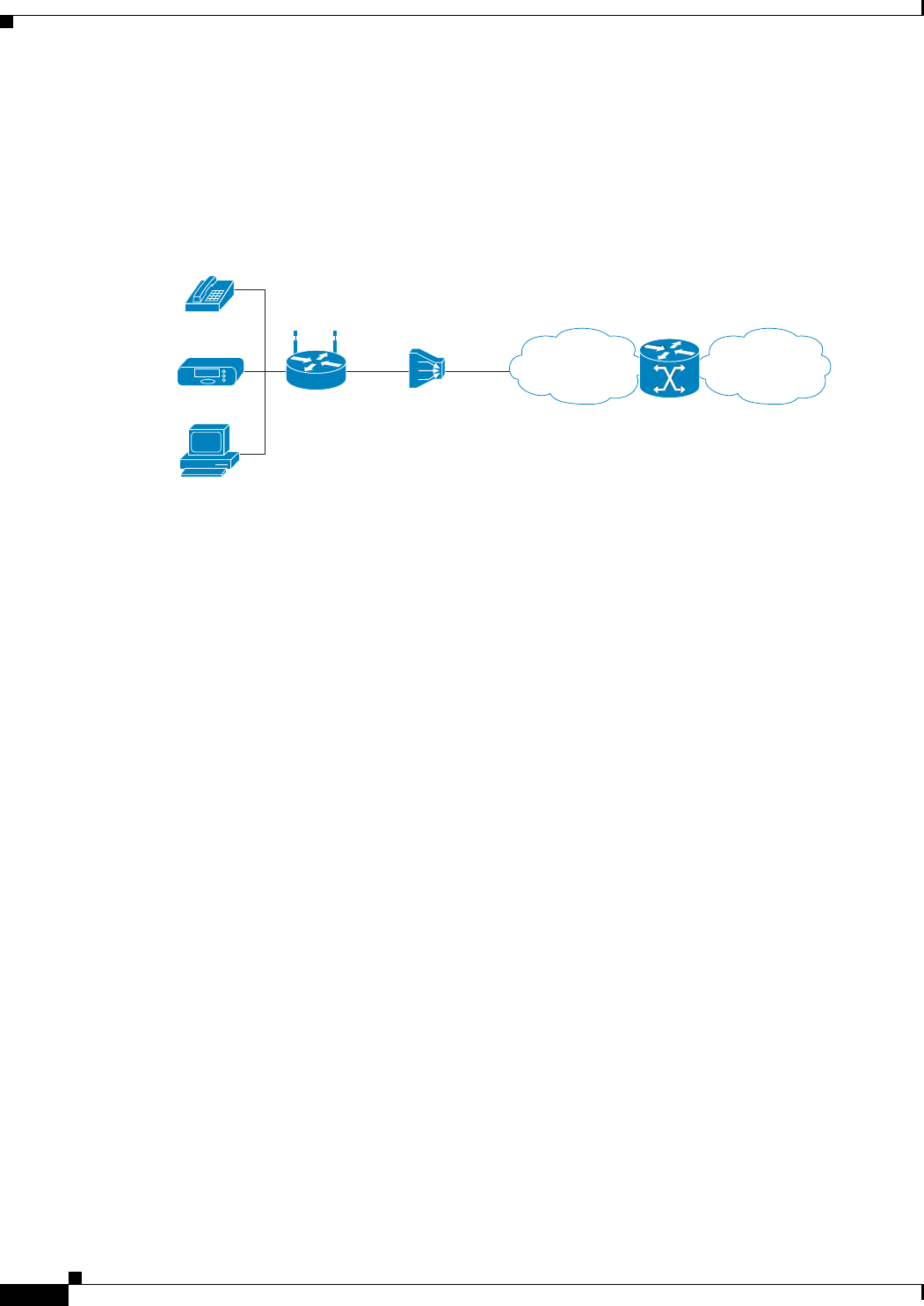
24-2
Cisco Prime Network 4.0 User Guide OL-29343-01
Chapter 24 Monitoring BNG Configurations
User Roles Required to Work With BNG
The network topology for BNG can be explained using the following models:
• BNG Retail Model—The subscriber connects to the network over a digital subscriber line (DSL)
circuit into a DSL access multiplexor (DSLAM), which aggregates a number of subscribers. The
DSLAMs are connected to an aggregation network, which grooms the subscriber traffic and
switches it to BNG. A sample of the retail model is shown in Figure 24-1.
Figure 24-1 BNG Retail Model
• BNG Wholesale Model—The subscriber’s traffic is handed off by the carrier (who still owns the
infrastructure) toone of the several Internet Service Providers (ISP). There are different ways to
make this handoff, Layer 2 Tunneling Protocol (L2TP) or Layer 3 virtual private networking (VPN)
being two such methods.
The BNG Retail model is used for deployment in Prime Network.
Prime Network provides BNG support for Cisco Aggregation Service Router (ASR) 9000 series network
elements.
The following topics describe more about the BNG configuration details:
• User Roles Required to Work With BNG, page 24-2
• Working with BNG Configurations, page 24-3
User Roles Required to Work With BNG
This topic identifies the roles that are required to work with BNG. Prime Network determines whether
you are authorized to perform a task as follows:
• For GUI-based tasks (tasks that do not affect elements), authorization is based on the default
permission that is assigned to your user account.
• For element-based tasks (tasks that do affect elements), authorization is based on the default
permission that is assigned to your account. That is, whether the element is in one of your assigned
scopes and whether you meet the minimum security level for that scope.
For more information on user authorization, see the topic on device scopes in the Cisco Prime Network
4.0 Administrator Guide.
COREAGG
Phone
PC
STB/TV HG DSLAM BNG
283650

24-3
Cisco Prime Network 4.0 User Guide
OL-29343-01
Chapter 24 Monitoring BNG Configurations Working with BNG Configurations
Working with BNG Configurations
This topic contains the following sections:
• View Broadband Access (BBA) Groups, page 24-3
• View Subscriber Access Points, page 24-5
• Diagnose Subscriber Access Points, page 24-6
• View Dynamic Host Configuration Protocol (DHCP) Service Profile, page 24-7
• View Dynamic Config Templates, page 24-9
• Viewing Policy Container, page 24-13
• Viewing QoS Profile, page 24-16
• Viewing AAA Configurations in Prime Network Vision, page 22-2
View Broadband Access (BBA) Groups
BBA groups refer to the configuration settings applicable to a subscriber session that are accessing the
network through an access interface. The same group can be applied to multiple access interfaces. For
example, the maximum session limit for an access interface.
To view the BBA group profile:
Step 1 Right-click on the device and choose the Inventory option.
Step 2 In the Inventory window, choose Logical Inventory > BNG > BBA Groups. A list of BBA groups is
displayed in the content pane as shown in Figure 24-2.
Table 24-1 Default Permission/Security Level Required for BNG
Task Viewer Operator OperatorPlus Configurator Administrator
View BBA profiles X X X X X
View Subscriber Access Points X X X X X
Diagnose Subscriber Access Points — — — X X
View DHCP Service Profile X X X X X
View IP Subscriber Template X X X X X
View PPP Templates X X X X X
View Service Templates X X X X X
View policy details X X X X X
View QoS profile X X X X X
View AAA Group profile X X X X X
View Dynamic Authorization profile X X X X X
View Radius Global Configuration
details XX X X X
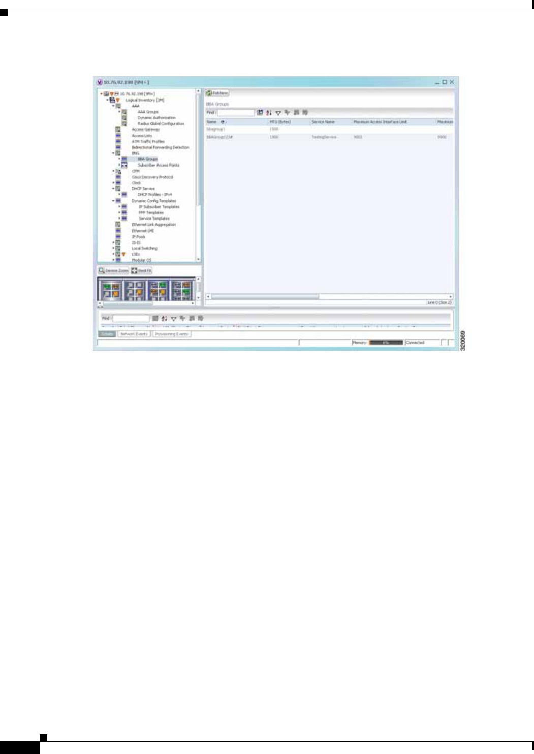
24-4
Cisco Prime Network 4.0 User Guide OL-29343-01
Chapter 24 Monitoring BNG Configurations
Working with BNG Configurations
Figure 24-2 BBA Groups Content Pane
Step 3 Right-click on a group from the list and choose Properties. The BBA Group Properties dialog box is
displayed.
Table 24-2 describes the fields that are displayed in the BBA Group Properties dialog box.

24-5
Cisco Prime Network 4.0 User Guide
OL-29343-01
Chapter 24 Monitoring BNG Configurations Working with BNG Configurations
View Subscriber Access Points
Subscriber access points refer to the access interfaces that are named based on the parent interface. For
example, bundle-ether 2.100.pppoe312. The subscribers on bundles (or bundle-VLANs) interfaces allow
redundancy and are managed on the route processor (RP). However, the subscribers over physical
interfaces are created and managed on the line card (LC) and are not redundant.
To view the subscriber access points profile:
Step 1 Right-click on the device and choose the Inventory option.
Step 2 In the Inventory window, choose Logical Inventory > BNG > Subscriber Access Points. A list of
access points is displayed in the content pane.
Step 3 Right-click on an access point from the list and choose Properties. The Subscriber Access Point
Properties dialog box is displayed.
Table 24-3 describes the fields that are displayed in the Subscriber Access Point Properties dialog box.
Table 24-2 BBA Group Properties
Field Name Description
Name The name of the BBA Group.
MTU (Bytes) The default maximum payload, which can be any value between 500 and
2000.
Service Name The name of the service configured under the specified BBA group.
Maximum Access
Interface Limit The maximum limit of PPP over Ethernet (PPPoE) sessions on the
access interface.
Maximum Circuit ID
Limit The maximum limit of PPPoE sessions for the circuit ID.
Maximum Session
Limit The maximum session limit per card. A warning is displayed if the
session exceeds the limit specified here.
Maximum MAC
Address Access Limit The maximum limit for MAC address access. A warning is displayed if
the access exceeds the limit specified here.
Maximum Payload
Limit The maximum payload limit.
Service Selection Indicates the status of advertising of unrequested services names. By
default, this service is enabled.
Applied Interfaces
Interface Name The name of the interface applied to the BBA Group.
Entity Association The link to the applied interface. Click this hyperlink to view the
relevant node under the Subscriber Access Point node.

24-6
Cisco Prime Network 4.0 User Guide OL-29343-01
Chapter 24 Monitoring BNG Configurations
Working with BNG Configurations
Diagnose Subscriber Access Points
The following commands can be launched from the inventory by right-clicking the BNG > Subscriber
Access Points node and selecting the Commands > Diagnose option. Before executing any commands,
you can preview them and view the results. If desired, you can also schedule the commands. To find out
if a device supports these commands, see the Cisco Prime Network 4.0 Supported Cisco VNEs.
Table 24-3 Subscriber Access Point Properties
Field Name Description
Access Point The name of the access point.
Associated Entity The link to the associated entity. Click this hyperlink to view the
associated Data Link Aggregation record under the Ethernet Link
Aggregation node.
Access Type The access type for the subscriber access point, which can be any one of
the following:
• PPPOE_AND_IP
• PPPOE
• IP
Ingress Service Policy The service policy for the access point, which when clicked will display
the relevant policy under the Policy Container node.
Ingress QoS Policy The Quality of Service policy for the inbound traffic, which when
clicked will display the relevant policy under the Policy Container node.
Egress QoS Policy The Quality of Service policy for the outbound traffic of the access
point, which when clicked will display the relevant policy under the
Policy Container node.
BBA Group The BBA group to which the access point is associated. Click this
hyperlink to view the relevant group under the BBA group node.
DHCP Profile The DHCP profile to which the access point is associated. Click this
hyperlink to view the relevant profile under the DHCP node.
IP Address The destination address for User Datagram Protocol (UDP) broadcasts.
VRF The Virtual Routing and Forwarding (VRF) in which the access points
operates.
Table 24-4 Diagnose Subscriber Access Points
Diagnose Command Input parameters
Show DHCP Binding Binding Type
Show IP Subscriber Management Trace • Trace Event Type
• Trace Count

24-7
Cisco Prime Network 4.0 User Guide
OL-29343-01
Chapter 24 Monitoring BNG Configurations Working with BNG Configurations
View Dynamic Host Configuration Protocol (DHCP) Service Profile
DHCP is used to automate host configuration by assigning IP addresses, delegating prefixes (in IPv6),
and providing extensive configuration information to network computers.
DHCP has the capability to allocate IP addresses only for a specified period of time, which is known as
the lease period. If a client device wants to retain the IP addresses for a period longer than the lease
period, then the client must renew the lease before it expires. A client can renew the lease depending on
the configuration time sent from the server. A REQUEST message is unicast by the client using the
server's IP address. On receiving the REQUEST message, the server responds with an acknowledgment,
and the client's lease is extended by the lease time configured in the acknowledgment message.
To view the DHCP service profile:
Step 1 Right-click on the required device and choose the Inventory option.
Step 2 In the Inventory window, choose Logical Inventory > DHCP Service > DHCP Profiles - IPv4. A list
of DHCP profiles are displayed in the content pane as shown in Figure 24-3.
Show PPoE Trace • Trace Filter Type
• Trace Count
Show Subscriber Dynamic Template Trace All • Trace Filter Type
• Trace Event Type
• Trace Count
Show Subscriber Manager Disconnect History Disconnect History Filter Type
Show Subscriber Manager Session History • Session Type
• ID Value
Show Subscriber Manager Trace • Trace Filter Type
• Trace Event Type
• Trace Count
Show Subscriber Session Details by Filter • Session Filter Type
• Filter Value
• Filter State
Table 24-4 Diagnose Subscriber Access Points (continued)
Diagnose Command Input parameters

24-8
Cisco Prime Network 4.0 User Guide OL-29343-01
Chapter 24 Monitoring BNG Configurations
Working with BNG Configurations
Figure 24-3 DHCP Profiles
Step 3 Right-click on a service from the list and choose Properties. The DHCP Profile Properties dialog box
is displayed.
Table 24-5 describes the fields that are displayed in the DHCP Profile Properties dialog box.

24-9
Cisco Prime Network 4.0 User Guide
OL-29343-01
Chapter 24 Monitoring BNG Configurations Working with BNG Configurations
View Dynamic Config Templates
A dynamic template is used to group configuration items, which are later applied to a group of
subscribers. This template is globally configured through the command line interface (CLI). However,
the template does not get applied to a subscriber interface as soon as it is configured. It must be activated
using a control policy. Similarly, you must deactivate the template using a control policy to remove its
association with the subscriber interface.
Ideally, you can activate more than one dynamic template on the same subscriber interface, for the same
event or different events. The same dynamic-template can be activated on multiple subscriber interfaces
through the same control policy.
Table 24-5 DHCP Profile Properties
Field Name Description
Profile Name The name of the DHCP profile.
Profile Type The network protocol that the profile belongs to. The profile type can be
IPV4 or IPV6.
Agent Mode The DHCP agent mode, which can be Relay, Snoop or Proxy.
Lease Limit The lease limit for the profile.
Lease Limit Type The lease limit type.
Relay Information
Check Indicates whether the relay information check is enabled or disabled.
Relay Information
Policy The relay information policy.
DHCP Agent Information Options
Option The relay agent information options key parameter.
Value The value of the relay agent information options.
Applied Interfaces
Interface Name The name of the interface applied to the DHCP Group.
Entity Association The link to the applied interface. Click this hyperlink to view the
relevant node under the Subscriber Access Point node.
DHCP Servers
Profile Class The profile class.
Server Address The IP address of the profile, which is used to relay packets.
VRF The VRF of the DHCP profile. Click this hyperlink to view the relevant
node under the VRFs node.
Gateway Address The IP address of the gateway.
Match Option The match option of the DHCP profile.
Match Option Value The value of the match option.
Match Option Mask The match option mask.

24-10
Cisco Prime Network 4.0 User Guide OL-29343-01
Chapter 24 Monitoring BNG Configurations
Working with BNG Configurations
Prime Network supports the following types of dynamic templates:
• IP subscriber templates
• PPP templates
• Service templates
To view the configuration templates:
Step 1 Right-click on the device and choose the Inventory option.
Step 2 In the Inventory window, choose Logical Inventory > Dynamic Config Templates > IP Subscriber
Templates or PPP template or Service template. A list of templates is displayed in the content pane.
Step 3 Select a template from the list, right-click and choose Properties to view its details.
Table 24-6 describes the fields that are displayed in the corresponding dialog box.

24-11
Cisco Prime Network 4.0 User Guide
OL-29343-01
Chapter 24 Monitoring BNG Configurations Working with BNG Configurations
Table 24-6 Template Properties
Field Name Description
Name The name of the subscriber template.
Template Type The template type, which can be IP Subscriber, PPP or Service based
on the selected template.
Ingress Policy The name of the ingress service policy associated with the subscriber
template. This field is applicable only for IP Subscriber and Service
templates.
Associated Ingress
Policy The associated ingress policy. Click this hyperlink to view the relevant
node under the Policy Container node. This field is applicable only for
IP subscriber templates.
Egress Policy The name of the egress service policy associated with the subscriber
template. This field is applicable only for IP Subscriber and Service
templates.
Associated Egress
Policy The associated egress policy. Click this hyperlink to view the relevant
node under the Policy Container node. This field is applicable only for
IP Subscriber and Service templates.
Ingress Access-List The name of the ingress access-list associated with the subscriber
template. This field is applicable only for IP subscriber templates.
Associated
Ingress-ACL Entity The associated ingress access list. Click this hyperlink to view the
related list in the Access List node. This field is applicable only for IP
subscriber templates.
Egress Access-List The name of the egress access-list associated with the subscriber
template. This field is applicable only for IP subscriber templates.
Associated Egress-ACL
Entity The associated egress access list. Click this hyperlink to view the related
list in the Access List node. This field is applicable only for IP
subscriber templates.
Mtu The maximum transmission unit for IPv4.
Idle Timeout The idle timeout for the subscriber template in seconds. This field is
applicable only for IP Subscriber and Service templates.
Keep Alive Enabled Indicates whether the Keep alive feature is enabled. This field is
applicable only for PPP templates.
Keep Alive Interval The keep alive interval time in terms of seconds. This field is applicable
only for PPP templates.
Maximum Bad
Authentication Request The maximum number of authentication failures, which can be any
value between 0 and 10. This field is applicable only for PPP templates.
Maximum
Unacknowledged
Request
The maximum number of unacknowledged configured requests, which
can be any value between 4 and 20. This field is applicable only for PPP
templates.
Maximum Negative
Acknowledgement The maximum number of consecutive configuration negative
acknowledgements, which can be any value between 2 and 10. This field
is applicable only for PPP templates.

24-12
Cisco Prime Network 4.0 User Guide OL-29343-01
Chapter 24 Monitoring BNG Configurations
Working with BNG Configurations
Viewing the Settings for a PPP Template
In addition to the above details, you can also view the following settings for a PPP template:
• IPCP Settings
• LCP Settings
• Authentication Settings
• PPP Timeout Settings
To view the settings:
Step 1 Right-click on the device and choose the Inventory option.
Step 2 In the Inventory window, choose Logical Inventory > Dynamic Config Templates > PPP template.
A list of templates is displayed in the content pane.
Step 3 Select a template from the list, right-click and choose Properties to view its details. You can click on
the tab to view more details. The IPCP tab is displayed by default.
Table 24-7 describes the fields that are displayed in the corresponding dialog box.
Table 24-7 PPP Template Settings
Field Name Description
DNS Server The IPCP negotiation primary and secondary DNS IP address.
WINS Server The IPCP negotiation primary and secondary WINS IP address.
IPAddress PoolName The IPCP negotiation name of the peer-address pool.
Associated IP Pool
Entity The associated IP pool entity for the template.
ReNegotiation Enabled Indicates whether the attempts by the peer to renegotiate IPCP is
enabled.
LCP Settings tab
Delay The time period (in seconds or milliseconds) to delay before starting
active LCP negotiations.
ReNegotiation Enabled Indicates whether the attempts by the peer to renegotiate LCP is enabled.
Authentication Settings tab
Authentication Type The PPP link authentication method, which can be any one of the
following:
• chap
• ms-chap
• pap
Chap Host Name The Challenge Handshake Authentication Protocol (CHAP) host name.
MS Chap Host Name The mobile station CHAP host name.
PPP Timeout Settings
Absolute Session
Timeout The absolute timeout for a PPP session.
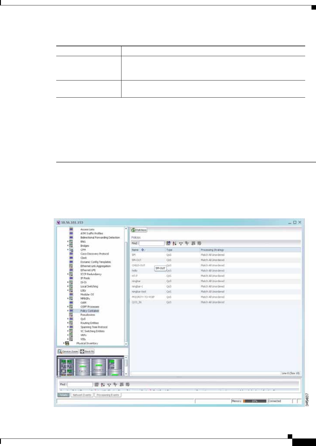
24-13
Cisco Prime Network 4.0 User Guide
OL-29343-01
Chapter 24 Monitoring BNG Configurations Viewing Policy Container
Viewing Policy Container
The Policy Container node in the logical inventory lists all the available service groups and service
policies that are associated with service templates, BBA groups, and subscriber access points.
To view the service group and service policy profiles:
Step 1 Right-click on the required device and choose the Inventory option.
Step 2 In the Inventory window, choose Logical Inventory > Policy Container. The Policies and Policy Group
tabs are displayed in the content pane. In the Policies tab, a list of existing policies are displayed as
shown in Figure 24-4.
Figure 24-4 Policy Container
Maximum
Authentication
Response WaitTime
The maximum time (in seconds) to wait for an authentication response
during a PPP negotiation.
Maximum
Authentication Retry The maximum time (in seconds) to wait for a response during a PPP
negotiation.
Table 24-7 PPP Template Settings (continued)
Field Name Description

24-14
Cisco Prime Network 4.0 User Guide OL-29343-01
Chapter 24 Monitoring BNG Configurations
Viewing Policy Container
Step 3 Click the Policy Group tab. A list of existing groups are displayed.
Step 4 Right-click on a group from the list and choose Properties. The Policy Group Properties dialog box is
displayed.
Table 24-8 describes the fields that are displayed in the Policy Group Properties dialog box.
Table 24-8 Policy Group Properties
Field Name Description
Name The name of the policy group.
Type The type of policy group, which can be any one of the following:
• Accounting
• Control
• PBR
• Performance Traffic
• QoS
• Traffic
• Redirect
Processing Strategy The strategy in applying the policy group, which can be any one of the
following:
• Match First
• Match All Unordered
• Match All Ordered
Policies
Name The name of the service policy map.
Type The type of policy map, which can be any one of the following:
• Accounting
• Control
• PBR
• Performance Traffic
• QoS
• Traffic
• Redirect
Processing Strategy The strategy in applying the policies on the incoming traffic, which can
be any one of the following:
• Match First
• Match All Unordered
• Match All Ordered

24-15
Cisco Prime Network 4.0 User Guide
OL-29343-01
Chapter 24 Monitoring BNG Configurations Viewing Policy Container
Step 5 Right-click on a policy from the Policies list and choose Properties. The Service Policy Properties
dialog box is displayed. Table 24-9 describes the fields that are displayed in the Service Policy Properties
dialog box.
Table 24-9 Service Policy Properties
Field Name Description
Name The name of the service policy map.
Type The type of policy map, which can be any one of the following:
• Accounting
• Control
• PBR
• Performance Traffic
• QoS
• Traffic
• Redirect
Processing Strategy The strategy in applying the policies on the incoming traffic, which can be
any one of the following:
• Match First
• Match All Unordered
• Match All Ordered
Policy Rules
Match Condition The class map associated with the policy rule.
Type The type of class map associated with the policy, which can be any one of
the following:
• Control Subscriber
• QoS
• Traffic
Action Execution
Strategy The policy execution strategy, which can be any of the following:
• Execute All
• Execute Until Success
• Execute Until Failure

24-16
Cisco Prime Network 4.0 User Guide OL-29343-01
Chapter 24 Monitoring BNG Configurations
Viewing QoS Profile
Viewing QoS Profile
QoS or Quality of services is the technique of prioritizing traffic flows and specifying preferences for
forwarding packets with higher priority. The QoS node in the logical inventory lists all the services
configured for the selected network element.
To view the QoS profile:
Step 1 Right-click on the device and choose the Inventory option.
Step 2 In the Inventory window, choose Logical Inventory > QoS > Class of Services. A list of existing
policies are displayed in the content pane.
Step 3 Right-click on a service in the list and choose Properties. The Class of Services Properties dialog box
is displayed. You can click on the tabs to view more details.
Table 24-10 describes the fields that are displayed in the Class of Services Properties dialog box.
Action Lists
Sequence Number The sequence number of the policy action.
Action Type The type of policy action, which can be any one of the following:
• Active
• Deactivate
• Apply
• Authenticate
• Authorize
• Set Timer
• Stop Timer
• Drop
• Accounting
• Conform Action
• Conform Color
• Exceed Action
• Exceed Color
• Child Conform Action
• Violation Action
Entity Type The type of entity affected by the policy rule, which can be Dynamic
template or Authorization list.
Entity Value The value of the dynamic template or authorization list.
Entity Association The associated entity. Click this hyperlink to view the relevant dynamic
template or authorization list.
Table 24-9 Service Policy Properties (continued)
Field Name Description

24-17
Cisco Prime Network 4.0 User Guide
OL-29343-01
Chapter 24 Monitoring BNG Configurations Viewing QoS Profile
Table 24-10 Class of Services Properties
Field Name Description
Name The name of the class of service.
Type The type of the class of service. Values are:
• Control Subscriber
• QoS
• Traffic
Matching Condition The matching condition for the service, which can be Match All or
Match Any.
Match Criteria Lists
Match Type The match type, which can be any one of the following:
• Access group
• ATM
• Auth status
• COS
• DEI
• Destination-address
• Discard-class
• Domain
• DSCP
• Ethertype
• FR-DE
• Frame-relay
• MPLS
• Precedence
• Protocol
• Qos-group
• Source-address
• Timer
• Username
• VLAN
• VPLS
Match Value The value associated with the match type.
Associated Entity The entity associated to the selected access group. Click this hyperlink
to view the related record in the Access List content pane.

24-18
Cisco Prime Network 4.0 User Guide OL-29343-01
Chapter 24 Monitoring BNG Configurations
Viewing QoS Profile

CHAPTER
25-1
Cisco Prime Network 4.0 User Guide
OL-29343-01
25
Monitoring Mobile Technologies
The following topics provide an overview of mobile technologies and describe how to work with mobile
technologies in Prime Network Vision:
• User Roles Required to Work with Mobile Technologies, page 25-1
• GPRS/UMTS Networks, page 25-4
• LTE Networks, page 25-40
• Scheduling 3GPP Inventory Retrieval Requests, page 25-109
• Viewing Operator Policies, APN Remaps, and APN Profiles, page 25-111
• Working with Active Charging Service, page 25-121
• Mobile Technologies Commands: Summary, page 25-138
User Roles Required to Work with Mobile Technologies
This topic identifies the GUI default permission or scope security level that is required to work with the
mobile technologies in Prime Network Vision. Prime Network determines whether you are authorized
to perform a task as follows:
• For GUI-based tasks (tasks that do not affect elements), authorization is based on the default
permission that is assigned to your user account.
• For element-based tasks (tasks that do affect elements), authorization is based on the default
permission that is assigned to your account. That is, whether the element is in one of your assigned
scopes and whether you meet the minimum security level for that scope.
For more information on user authorization, see the Cisco Prime Network 4.0 Administrator Guide.
The following tables identify the tasks that you can perform:
• Table 25-1 identifies the tasks that you can perform if a selected element is not in one of your
assigned scopes.
• Table 25-2 identifies the tasks that you can perform if a selected element is in one of your assigned
scopes.
By default, users with the Administrator role have access to all managed elements. To change the
Administrator user scope, see the topic on device scopes in the Cisco Prime Network 4.0 Administrator
Guide.

25-2
Cisco Prime Network 4.0 User Guide OL-29343-01
Chapter 25 Monitoring Mobile Technologies
User Roles Required to Work with Mobile Technologies
Table 25-1 Default Permission/Security Level Required for Viewing GGSN, GTPU, and APN
Properties - Element Not in User’s Scope
Task Viewer Operator OperatorPlus Configurator Administrator
Viewing GGSN properties — — — — X
Viewing additional characteristics of a
GGSN —— — — X
Working with GGSN commands — — — — X
Viewing GTPU properties — — — — X
Working with GTPU commands — — — — X
Viewing APN properties — — — — X
Viewing additional characteristics of
an APN —— — — X
Working with APN commands — — — — X
Viewing SAE-GW properties — — — — X
Viewing P-GW properties — — — — X
Working with P-GW commands — — — — X
Viewing S-GW properties — — — — X
Working with S-GW commands — — — — X
Viewing GTPP properties — — — — X
Viewing additional characteristics of a
GTPP —— — — X
Working with GTPP commands — — — — X
Viewing EGTP properties — — — — X
Working with EGTP commands — — — — X
Viewing operator policies — — — — X
Viewing APN remaps — — — — X
Viewing APN profiles — — — — X
Viewing additional characteristics of
an APN profiles —— — — X
Viewing active charging services
(ACS) —— — — X
Working with ACS commands — — — — X
Viewing QCI-QoS mapping — — — — X
Viewing the Layer 2 Tunnel Access
Concentrator Configurations —— — — X
Viewing the HSGW configuration — — — — X
Viewing the Home Agent
configuration —— — — X
Viewing the Foreign Agent
configuration details —— — — X

25-3
Cisco Prime Network 4.0 User Guide
OL-29343-01
Chapter 25 Monitoring Mobile Technologies User Roles Required to Work with Mobile Technologies
Viewing the ePDG configuration
details —— — — X
Viewing the PDSN configuration
details —— — — X
Viewing the Local Mobility Anchor
configuration —— — — X
Table 25-2 Default Permission/Security Level Required for Viewing GGSN, GTPU, and APN
Properties - Element in User’s Scope
Task Viewer Operator OperatorPlus Configurator Administrator
Viewing GGSN properties X X X X X
Viewing additional characteristics of a
GGSN XX X X X
Working with GGSN commands — — — X X
Viewing GTPU properties X X X X X
Working with GTPU commands — — — X X
Viewing APN properties X X X X X
Viewing additional characteristics of
an APN XX X X X
Working with APN commands — — — X X
Viewing SAE-GW properties X X X X X
Viewing P-GW properties X X X X X
Working with P-GW commands — — — X X
Viewing S-GW properties X X X X X
Working with S-GW commands — — — X X
Viewing GTPP properties X X X X X
Viewing additional characteristics of a
GTPP XX X X X
Working with GTPP commands — — — X X
Viewing EGTP properties X X X X X
Working with EGTP commands — — — X X
Viewing operator policies X X X X X
Viewing APN remaps X X X X X
Viewing APN profiles X X X X X
Viewing additional characteristics of
an APN profiles XX X X X
Table 25-1 Default Permission/Security Level Required for Viewing GGSN, GTPU, and APN
Properties - Element Not in User’s Scope (continued)
Task Viewer Operator OperatorPlus Configurator Administrator

25-4
Cisco Prime Network 4.0 User Guide OL-29343-01
Chapter 25 Monitoring Mobile Technologies
GPRS/UMTS Networks
GPRS/UMTS Networks
These topics describe how to use Prime Network to manage GPRS/UMTS networks:
• Overview of GPRS/UMTS Networks, page 25-4
• Working With GPRS/UMTS Network Technologies, page 25-6
Overview of GPRS/UMTS Networks
General Packet Radio Service (GPRS) and Universal Mobile Telecommunication System (UMTS) are
evolutions of Global System for Mobile Communication (GSM) networks.
GPRS is a 2.5G mobile communications technology that enables mobile wireless service providers to
offer their mobile subscribers packet-based data services over GSM networks. UMTS is a 3G mobile
communications technology that provides wideband code division multiple access (CDMA) radio
technology. Figure 25-1 shows a basic GPRS/UMTS network topology.
Viewing active charging services
(ACS) XX X X X
Working with ACS commands — — — X X
Viewing QCI-QoS mapping X X X X X
Viewing the Layer 2 Tunnel Access
Concentrator Configurations XX X X X
Viewing the HSGW configuration X X X X X
Viewing the Home Agent
configuration XX X X X
Viewing the Foreign Agent
configuration details XX X X X
Viewing the ePDG configuration
details XX X X X
Viewing the PDSN configuration
details XX X X X
Viewing the Local Mobility Anchor
configuration XX X X X
Table 25-2 Default Permission/Security Level Required for Viewing GGSN, GTPU, and APN
Properties - Element in User’s Scope (continued)
Task Viewer Operator OperatorPlus Configurator Administrator
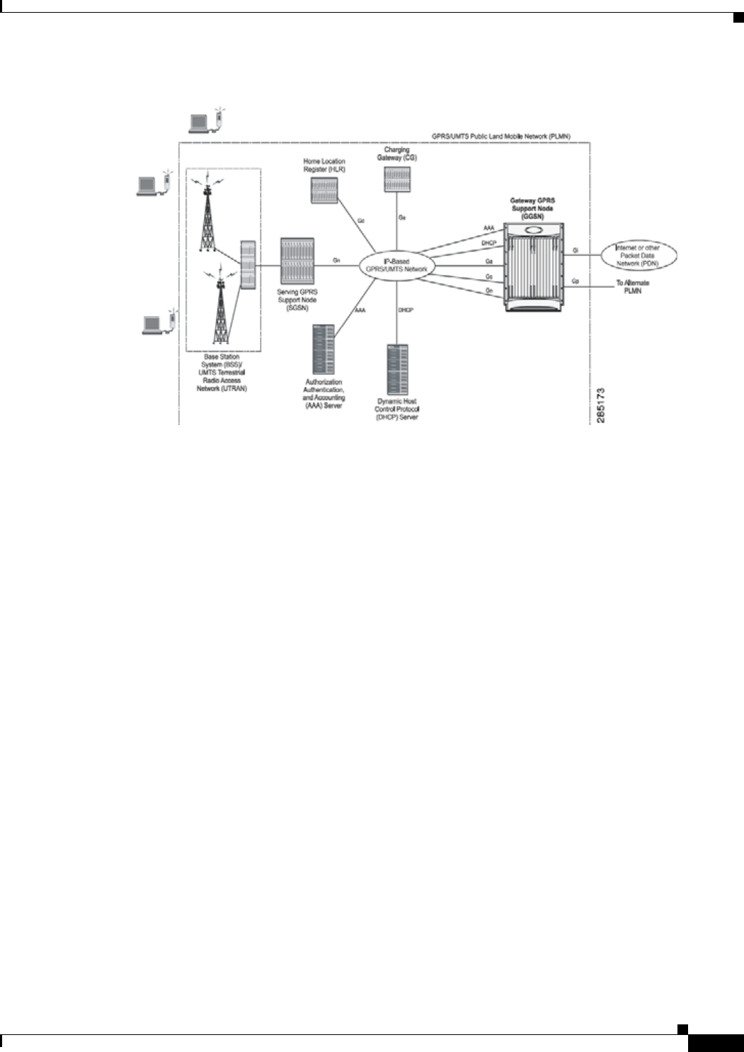
25-5
Cisco Prime Network 4.0 User Guide
OL-29343-01
Chapter 25 Monitoring Mobile Technologies GPRS/UMTS Networks
Figure 25-1 Basic GPRS/UMTS Network Topology
The GPRS/UMTS packet core comprises two major network elements:
• Gateway GPRS support node (GGSN)—A gateway that provides mobile cell phone users access to
a Packet Data Network (PDN) or specified private Internet Protocol (IP) networks.
• Serving GPRS support node (SGSN)—Connects the radio access network (RAN) to the
GPRS/UMTS core and tunnels user sessions to the GGSN. The SGSN sends data to and receives
data from mobile stations, and maintains information about the location of a mobile station (MS).
The SGSN communicates directly with the MS and the GGSN.
PDNs are associated with Access Point Names (APNs) configured on the system. Each APN consists of
a set of parameters that dictate how subscriber authentication and IP address assignment is to be handled
for that APN.
Prime Network Vision allows you to configure the mobile technologies by using commands and also
view the properties configured for the mobile technologies. Figure 25-2 shows an example of the
Inventory window with the mobile technology nodes/containers under the Mobile context.
From Prime Network 3.9, the mobile technologies are supported on Cisco Aggregation Service
Router (ASR) 5000 series mobile gateways.
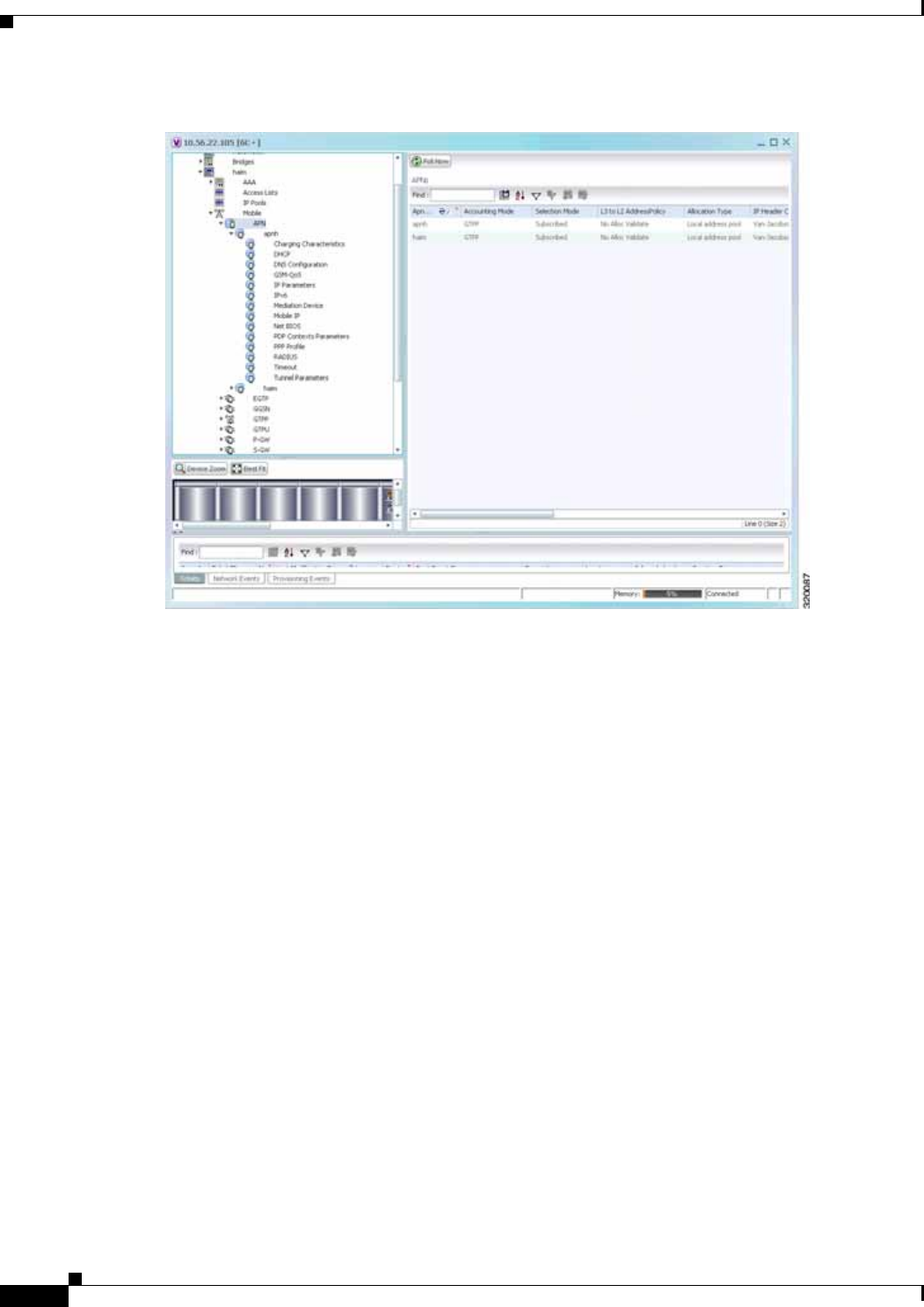
25-6
Cisco Prime Network 4.0 User Guide OL-29343-01
Chapter 25 Monitoring Mobile Technologies
GPRS/UMTS Networks
Figure 25-2 Mobile Technology Nodes in Logical Inventory
Working With GPRS/UMTS Network Technologies
The following topics explain how to work with GPRS/UMTS network technologies in Prime Network
Vision:
• Working with the Gateway GPRS Support Node(GGSN), page 25-6
• Working with the GPRS Tunneling Protocol User Plane (GTPU), page 25-11
• Working with Access Point Names (APNs), page 25-13
• Working with GPRS Tunneling Protocol Prime (GTPP), page 25-23
• Working with the Evolved GPS Tunneling Protocol (eGTP), page 25-30
• Monitoring the Serving GPRS Support Node (SGSN), page 25-32
Working with the Gateway GPRS Support Node(GGSN)
The GGSN works in conjunction with SGSNs within the network to perform the following functions:
• Establish and maintain subscriber Internet Protocol (IP) or Point-to-Point Protocol (PPP) type
Packet Data Protocol (PDP) contexts originated by either the mobile or the network.
• Provide charging detail records (CDRs) to the charging gateway ((CG), also known as the Charging
Gateway Function (CGF)).
• Route data traffic between the subscriber’s Mobile Station (MS) and a PDN such as the Internet or
an intranet.

25-7
Cisco Prime Network 4.0 User Guide
OL-29343-01
Chapter 25 Monitoring Mobile Technologies GPRS/UMTS Networks
In addition, to providing basic GGSN functionality as described above, the system can be configured to
support Mobile IP and/or Proxy Mobile IP data applications in order to provide mobility for subscriber
IP PDP contexts. When supporting these services, the system can be configured to function as a GGSN
and Foreign Agent (FA), a stand-alone Home Agent (HA), or a GGSN, FA, and HA simultaneously
within the carrier's network.
The following topics explain how to work with GGSN in Prime Network Vision:
• Viewing GGSN Properties, page 25-7
• Viewing Additional Characteristics of a GGSN, page 25-8
• GGSN Commands, page 25-10
Viewing GGSN Properties
Prime Network Vision displays the GGSNs in a GGSN container under the Mobile node in the logical
inventory. The icon used for representing GGSNs in the logical inventory is explained in Logical
Inventory Icons, page A-7.
To view GGSN properties:
Step 1 Right-click the required device in Prime Network Vision and choose Inventory.
Step 2 In the logical inventory window, choose Logical Inventory > Context > Mobile > GGSN Container.
Prime Network Vision displays the list of GGSNs configured under the container. You can view the
individual GGSN details from the table on the right pane or by choosing Logical
Inventory > Context > Mobile > GGSN Container > GGSN.
Table 25-3 describes the details available for each GGSN.
Table 25-3 GGSN Properties in Logical Inventory
Field Description
Service Name The name of the GGSN service.
Status The status of the GGSN service. Value could be Unknown, Running, or
Down.
PLMN Policy The PLMN policy for handling communications from SGSNs that are not
configured to communicate with.
Newcall Policy Specifies whether to accept or reject a new incoming call.
Authentication Server
Timeout The code used by the GGSN as a response message if communication with
an authentication server times out. Value could be System Failure or User
Authentication Failed.
Accounting Server
Timeout The code used by the GGSN as a response message if communication with
an accounting server times out. Value could be System Failure or No
Resouces.
GTPU The GTPU that is associated with the GGSN and manages the GTP messages
between GGSN and a radio access network equipment (RNC).
Accounting Context The context that processes accounting for PDP contexts handled by the
GGSN service.
Local IP Address The local IP address bounded with the GGSN service.

25-8
Cisco Prime Network 4.0 User Guide OL-29343-01
Chapter 25 Monitoring Mobile Technologies
GPRS/UMTS Networks
If the GGSN is associated with SGSNs and Public Land Mobile Networks (PLMNs), you can view the
details from the respective tabs for that GGSN.
Table 25-4 describes the SGSN and PLMN information associated with the GGSN.
Viewing Additional Characteristics of a GGSN
To view additional characteristics of a GGSN:
Step 1 Right-click the required device in Prime Network Vision and choose Inventory.
Step 2 In the logical inventory window, choose Logical Inventory > Mobile > GGSN Container >GGSN.
Step 3 Expand the GGSN node. The following list of characteristics configured for the GGSN are displayed:
• Charging Characteristics
• Timers And QoS
Step 4 Choose Charging Characteristics to view the properties on the right pane. See Table 25-5 for more
details on the charging characteristics configured for the GGSN.
Table 25-4 SGSN and PLMN information for a GGSN
Field Description
SGSNs
IP Address The IP address of the SGSN.
Subnet Mask The subnet mask of the SGSN.
PLMN ID The PLMN ID associated with the SGSN.
MCC The mobile country code (MCC) portion of the PLMN.
MNC The mobile network code (MNC) portion of the PLMN.
PLMN Foreign Indicates whether the SGSN belongs to a home or foreign PLMN. This field
is available only if MCC and MNC are not available.
Reject Foreign
Subscriber Specifies whether to accept or reject foreign subscriber. Value could be True
or False.
RAT Type The type of radio access technology (RAT) that is used for communication.
Description The description of the SGSN entry in the GGSN service.
PLMNs
PLMN ID The ID of the PLMN associated with the GGSN.
Primary Indicates whether the PLMN ID is the primary PLMN ID for the GGSN.
Value could be True or False. When multiple PLMN IDs are configured, the
one configured as primary is used for the Authentication, Authorization, and
Accounting (AAA) attribute.

25-9
Cisco Prime Network 4.0 User Guide
OL-29343-01
Chapter 25 Monitoring Mobile Technologies GPRS/UMTS Networks
Step 5 Under the GGSN node, choose Timers and QoS to view the properties on the right pane. See Table 25-6
for more details on the Timers and QoS parameters configured for the GGSN.
Table 25-5 GGSN Charging Characteristics
Field Description
Profiles
Profile No Type of billing. For example:
• 1—Hot billing
• 2—Flat billing
• 4—Prepaid billing
• 8—Normal billing
All other profiles from 0 - 15 are customized billing types.
Buckets Denotes container changes in the GGSN Call Detail Record (GCDR).
Prepaid Prepaid type, which could be Prohibited or Use-rulebase-configuration.
Down Link Octets Downlink traffic volume of the bucket.
Uplink Octets Uplink traffic volume of the bucket.
Total Octets Total traffic volume of the bucket.
Tariff Time Triggers
Profile No Type of billing.
Time1, Time2, and so
on First time-of-day time values, and so on, to close the current statistics
container.
Intervals
Profile No Type of billing.
No. of SGSNs Number of SGSN changes (inter-SGSN switchovers) resulting in a new
Routing Area Identity (RAI) that can occur before closing an accounting
record.
Interval Normal time duration that must elapse before closing an accounting record.
Down Link Octets Downlink traffic volume reached within the time interval.
Up Link Octets Uplink traffic volume reached within the time interval.
Total Octets Total traffic volume reached within the time interval.
Table 25-6 GGSN Timers and QoS
Field Description
Retransmission
Timeout Timeout, in seconds, for retransmission of GTP control packets.
Max Retransmissions Maximum retries for transmitting GTP control packets.
Setup Timeout Maximum time, in seconds, allowed for session setup.
Echo Interval Echo interval, in seconds, for GTP.

25-10
Cisco Prime Network 4.0 User Guide OL-29343-01
Chapter 25 Monitoring Mobile Technologies
GPRS/UMTS Networks
GGSN Commands
The following commands can be launched from the inventory by right-clicking a GGSN and choosing
GGSN > Commands > Configuration.
The table below lists the GGSN configuration commands. Additional commands may be available for
your devices. New commands are often provided in Prime Network Device Packages, which can be
downloaded from the Prime Network software download site. For more information on how to download
and install DPs and enable new commands, see the information on “Adding Additional Device (VNE)
support” in the Cisco Prime Network 4.0 Administrator Guide.
Before executing any commands, you can preview them and view the results. If desired, you can also
schedule the commands. To find out if a device supports these commands, see the Cisco Prime Network
4.0 Supported Cisco VNEs.
Note You might be prompted to enter your device access credentials while executing a command. Once you
have entered them, these credentials will be used for every subsequent execution of a command in the
same GUI client session. If you want to change the credentials, click Edit Credentials. The Edit
Credentials button will not be available for SNMP commands or if the command is scheduled for a later
time.
Guard Interval Interval, in seconds, for which the GGSN maintains responses sent to SGSN.
This optimizes the handling of retransmitted messages.
QCI to DSCP Mapping
QoS class index A set of transport characteristics used to differentiate various packet flows.
DSCP Differentiated Services Code Point (DSCP), a mechanism for classifying and
managing network traffic and providing QoS.
QCI & ARP DSCP Mapping
QoS class index A set of transport characteristics used to differentiate various packet flows.
Allocation retention
priority The priority of allocation and retention of the service data flow. This
parameter allows prioritizing allocation of resources during bearer
establishment and modification. During network traffic congestions, a lower
ARP flow is dropped to free up the capacity.
DSCP A mechanism for classifying and managing network traffic and providing
QoS.
Table 25-6 GGSN Timers and QoS (continued) (continued)
Field Description

25-11
Cisco Prime Network 4.0 User Guide
OL-29343-01
Chapter 25 Monitoring Mobile Technologies GPRS/UMTS Networks
Working with the GPRS Tunneling Protocol User Plane (GTPU)
The GGSN communicates with SGSNs on a Public Land Mobile Network (PLMN) using the GPRS
Tunneling Protocol (GTP). The signaling or control aspect of this protocol is referred to as the GTP
Control Plane (GTPC) while the encapsulated user data traffic is referred to as the GTP User Plane
(GTPU). GTPU is used for transferring user data in separated tunnels for each PDP context.
You can configure various parameters for a GTPU using the configuration commands in Prime Network
Vision. You can view the configured parameters for a GTPU in the logical inventory.
The following topics explain how to work with GTPU in Prime Network Vision:
• Viewing GTPU Properties, page 25-11
• GTPU Commands, page 25-12
Viewing GTPU Properties
Prime Network Vision displays the GTPUs in a GTPU container under the Mobile node in the logical
inventory. The icon used for representing GTPUs in the logical inventory is explained in Logical
Inventory Icons, page A-7.
To view GTPU properties:
Step 1 Right-click the required device in Prime Network Vision and choose Inventory.
Step 2 In the logical inventory window, choose Logical Inventory > Context > Mobile > GTPU Container.
Prime Network Vision displays the list of GTPUs configured under the container. You can view the
individual GTPU details from the table on the right pane or by choosing Logical
Inventory >Context > Mobile > GTPU Container > GTPU.
Table 25-8 describes the details available for each GTPU.
Table 25-7 GGSN Commands
Command Navigation Description
Create PLMN Identifier Right-click on a
GGSN group >
Commands >
Configuration
Use this command to create a PLMN
Identifier.
Create SGSN Use this command to create an SGSN.
Delete GGSN Use this command to delete a GGSN
profile.
Modify GGSN Use this command to modify a GGSN
profile details.

25-12
Cisco Prime Network 4.0 User Guide OL-29343-01
Chapter 25 Monitoring Mobile Technologies
GPRS/UMTS Networks
GTPU Commands
The following commands can be launched from the inventory by right-clicking a GTPU and choosing
Commands > Configuration.
The table below lists the GTPU configuration commands. Additional commands may be available for
your devices. New commands are often provided in Prime Network Device Packages, which can be
downloaded from the Prime Network software download site. For more information on how to download
and install DPs and enable new commands, see the information on “Adding Additional Device (VNE)
support” in the Cisco Prime Network 4.0 Administrator Guide.
Before executing any commands, you can preview them and view the results. If desired, you can also
schedule the commands. To find out if a device supports these commands, see the Cisco Prime Network
4.0 Supported Cisco VNEs.
Note You might be prompted to enter your device access credentials while executing a command. Once you
have entered them, these credentials will be used for every subsequent execution of a command in the
same GUI client session. If you want to change the credentials, click Edit Credentials. The Edit
Credentials button will not be available for SNMP commands or if the command is scheduled for a later
time.
Table 25-8 GTPU Properties in Logical Inventory
Field Description
Service Name The name of the GTPU service.
State The status of the GTPU service. Status could be Unknown, Running, or
Down.
Max Retransmissions The maximum limit for GTPU echo retransmissions. Default value is 4.
Retransmission
Timeout The timeout in seconds for GTPU echo retransmissions. Default value is 5
Secs.
Echo Interval The rate at which the GTPU echo packets are sent.
IPSEC Tunnel Idle
Timeout
The IPSec tunnel idle timeout after which IPSec tunnel deletion is triggered.
Default value is 60 Secs.
Allow Error Indication Specifies whether error indication is dropped or sent without IPSec tunnel.
Default value is Disabled.
Include UDP Port Ext
Hdr Specifies whether to include an extension header in the GTPU packet for
error indication messages. Default value is False.
IP Address The list of IP addresses configured on the GTPU. The IP addresses are
available only when configured for the GTPU.

25-13
Cisco Prime Network 4.0 User Guide
OL-29343-01
Chapter 25 Monitoring Mobile Technologies GPRS/UMTS Networks
Working with Access Point Names (APNs)
APN is the access point name that is configured in the GGSN configurations. The GGSN’s APN support
offers the following benefits:
• Extensive parameter configuration flexibility for the APN.
• Extensive QoS support.
• Virtual APNs to allow differentiated services within a single APN. The APN that is supplied by the
mobile station is evaluated by the GGSN in conjunction with multiple configurable parameters.
Then the GGSN selects an APN configuration based on the supplied APN and those configurable
parameters.
• Traffic policing that governs the subscriber traffic flow if it violates or exceeds configured peak or
committed data rates. The traffic policing attributes represent a QoS data rate limit configuration for
both uplink and downlink directions.
Up to 1024 APNs can be configured in the GGSN. An APN may be configured for any type of PDP
context, i.e., PPP, IPv4, IPv6 or both IPv4 and IPv6.
Many parameters can be configured independently for each APN on the device. They are categorized as
given below:
• Accounting—Various parameters regarding accounting possibilities, such as, charging
characteristics, accounting mode (RADIUS server-based accounting, GTPP-based accounting, and
so on.)
• Authentication—Various parameters regarding authentication, such as, protocols used, like,
Challenge Handshake Authentication Protocol (CHAP), Password Authentication Protocol (PAP),
or none, default username/password, server group to use, and limit for number of PDP contexts.
• Enhanced Charging—Name of rulebase to use, which holds the enhanced charging configuration
(for example, eG-CDR variations, charging rules, prepaid/postpaid options, etc.).
Table 25-9 GTPU Commands
Command Navigation Description
Create GTPU Bind IP Address Right-click on a
GTPU
defined > Comm
ands > Configur
ation
Use this command to create a bind IP
address for GTPU.
Modify GTPU Bind IP Address Select the GTPU
node > right-click
on an IP address
in the content
pane
> Commands >
Configuration
Use this command to modify the Bind IP
address for GTPU.
Delete GTPU Bind IP Address Use this command to delete the Bind IP
address for GTPU.
Delete GTPU Right-click on a
GTPU
defined > Comm
ands > Configur
ation
Use this command to delete a GTPU
group.
Modify GTPU Use this command to modify a GTPU
group.

25-14
Cisco Prime Network 4.0 User Guide OL-29343-01
Chapter 25 Monitoring Mobile Technologies
GPRS/UMTS Networks
• IP: Method for IP address allocation (e.g., local allocation by GGSN, Mobile IP, Dynamic Host
Control Protocol (DHCP), DHCP relay, etc.). IP address ranges, with or without overlapping ranges
across APNs.
• Tunneling: PPP may be tunneled with L2TP. IPv4 may be tunneled with GRE, IP-in-IP or L2TP.
Load-balancing across multiple tunnels. IPv6 is tunneled in IPv4. Additional tunneling techniques,
such as, IPsec and VLAN tagging may be selected by the APN, but are configured in the GGSN
independently from the APN.
• QoS: IPv4 header ToS handling. Traffic rate limits for different 3GPP traffic classes. Mapping of
R98 QoS attributes to work around particular handset defections. Dynamic QoS renegotiation
(described elsewhere).
You can configure the APN parameters using Prime Network Vision. You can view the configured
parameters for an APN in the logical inventory. After an APN is determined by the GGSN, the subscriber
may be authenticated/authorized with an AAA server. The GGSN allows the AAA server to return
Vendor Specific Attributes (VSAs) that override any or all of the APN configuration. This allows
different subscriber tier profiles to be configured in the AAA server, and passed to the GGSN during
subscriber authentication/authorization.
The following topics explain how to work with APN in Prime Network Vision:
• Viewing APN Properties, page 25-14
• Viewing Additional Characteristics of an APN, page 25-18
• APN Commands, page 25-22
Viewing APN Properties
Prime Network Vision displays the APNs in an APN container under the Mobile node in the logical
inventory. You can also view additional characteristics configured on the APN as explained in Viewing
Additional Characteristics of an APN, page 25-18. The icon used for representing APNs in the logical
inventory is explained in Logical Inventory Icons, page A-7.
To view APN properties:
Step 1 Right-click the required device in Prime Network Vision and choose Inventory.
Step 2 In the logical inventory window, choose Logical Inventory >Context > Mobile > APN
Container >APN.
Table 25-10 describes the information that is available for the APN. The information that is displayed
depends on the configuration of the APN.
Table 25-10 APN Properties in Logical Inventory
Field Description
APN Name The APN name.
Accounting Mode The accounting protocol in use in the APN. Values are GTPP (GPRS
Tunneling Protocol Prime), RADIUS (Remote Authentication Dial In User
Service), or None.
Selection Mode The selection mode in use in the APN. Selection mode indicates the origin
of the requested APN and whether or not the Home Location Register (HLR)
has verified the user subscription.
L3 to L2 Address Policy The layer 2 to layer 3 IP address allocation or validation policy.

25-15
Cisco Prime Network 4.0 User Guide
OL-29343-01
Chapter 25 Monitoring Mobile Technologies GPRS/UMTS Networks
Step 3 To view additional details configured for the APN, use the following tabs:
• Virtual APNs—A virtual APN is a non-physical entity that represents an access point that does not
itself provide direct access to a real target network. A virtual APN can be used to consolidate access
to multiple, physical target networks through a single access point.
• QCI to DSCP Mapping—Shows the mapping between QoS Class Indices (QCI) to Differentiated
Services Code Point (DSCP).
• QCI & ARP DSCP Mapping—Shows the mapping between QCI and Allocation/Retention Priority
(ARP) to DSCP.
• QoS Downlink Traffic Policing—Shows the attributes that represent QoS data rate limit
configuration for downlink direction within the APN profile.
• QoS Uplink Traffic Policing—Shows the attributes that represent QoS data rate limit configuration
for uplink direction within the APN profile.
Allocation Type The method by which the APN obtains IP addresses for PDP contexts.
IP Header Compression IP packet header compression parameters for the APN.
New Call Policy Specifies whether to accept or reject a new incoming call in case of duplicate
session calls with a request for same IP address.
Table 25-10 APN Properties in Logical Inventory (continued)
Field Description
Table 25-11 Additional Configuration Details for APN
Field Description
Virtual APNs
Preference Specifies the order in which the referenced APNs are compared by the
system. Can be configured to any integer value from 1 (highest priority) to
1000 (lowest priority).
APN Specifies the name of an alternative APN configured on the system that is to
be used for PDP contexts with matching properties. Value can be from 1 to
62, alpha and/or numeric characters, and is not case-sensitive. It may also
contain dots ( . ) and/or dashes (- ).

25-16
Cisco Prime Network 4.0 User Guide OL-29343-01
Chapter 25 Monitoring Mobile Technologies
GPRS/UMTS Networks
Rule Definition The virtual APN rule definition can be one of the following:
• access-gw-address—Specifies the access gateway (SGSN/SGW/Others)
address for the virtual APN. The IP address can be an IPv4 or IPv6
address in decimal notation. IPv6 also supports :: notation for the IP
address.
• bearer-access-service—Specifies the bearer access service name for the
virtual APN.
• service name—Specifies the service name. Service name is unique
across all the contexts. Value is a string of size 1 to 63.
• cc-profile—Specifies the APN for charging characteristics (CC) profile
index. Value is an integer from 1 to 15.
• Domain name—Specifies the subscriber’s domain name (realm).
Domain name can be from 1 to 79 alpha and/or numeric characters.
• MCC—Specifies the MCC portion of the PLMN identifier. Value is an
integer between 100 to 999.
• MNC—Specifies the MNC portion of the PLMN identifier. Value is an
integer between 100 to 999.
• msisdn-range—Specifies the APN for this MSISDN range. The starting
and ending values of the range is a string of size 2 to 15 with values
between 00 and 999999999999999.
• Rat-Type—Specifies the rat-type option, which could be gan, geran,
hspa, utran, or wlan.
• Roaming mode—Specifies the roaming mode, which could be Home,
Visiting, or Roaming.
QCI to DSCP Mapping
QoS class index Denotes a set of transport characteristics used to differentiate various packet
flows.
DSCP Denotes a mechanism for classifying and managing network traffic and
providing QoS.
QCI & ARP DSCP Mapping
QoS class index Denotes a set of transport characteristics used to differentiate various packet
flows.
Allocation retention
priority Indicates the priority of allocation and retention of the service data flow. This
parameter allows prioritizing allocation of resources during bearer
establishment and modification. During network traffic congestions, a lower
ARP flow is dropped to free up the capacity.
DSCP Denotes a mechanism for classifying and managing network traffic and
providing QoS.
QoS Downlink Traffic Policing
QCI A scalar that denotes a set of transport characteristics and used to infer nodes
specific parameters that control packet forwarding treatment.
Peak Data Rate The peak data rate allowed, in bytes, for the downlink direction and QoS
traffic class.
Table 25-11 Additional Configuration Details for APN (continued)
Field Description

25-17
Cisco Prime Network 4.0 User Guide
OL-29343-01
Chapter 25 Monitoring Mobile Technologies GPRS/UMTS Networks
Committed Data Rate The committed data rate allowed, in bytes, for the downlink direction and
QoS traffic class.
Negotiate Limit Indicates whether negotiation limit is enabled or disabled for the downlink
direction and Qos traffic class.
Rate Limit Indicates whether the rate limit is enabled or disabled for the downlink
direction and Qos traffic class.
Burst Size Auto
Readjust Indicates whether the auto readjustment of burst size is enabled or disabled.
This parameter is used in dynamic burst size calculation, for traffic policing,
at the time of PDP activation of modification.
Burst Size Auto
Readjust Duration The burst size readjustment duration in seconds. This parameter indicates the
number of seconds that the dynamic burst size calculation will last for. This
allows the traffic to be throttled at the negotiated rates.
Peak Burst Size (bytes) The peak burst size allowed, in bytes, for the downlink direction and QoS
class.
Guaranteed Burst Size
(bytes) The guaranteed burst size allowed, in bytes, for the downlink direction and
QoS class.
Exceed Action The action to be taken on packets that exceed the committed data rate, but do
not violate the peak data rate. The action could be one of the following:
• Drop
• Lower IP Precedence
• Transmit
Violate Action The action to be taken on packets that exceed both committed and peak data
rates. The action could be one of the following:
• Drop
• Lower IP Precedence
• Shape
• Transmit
QoS Uplink Traffic Policing
QCI A scalar that denotes a set of transport characteristics and used to infer nodes
specific parameters that control packet forwarding treatment.
Peak Data Rate The peak data rate allowed, in bytes, for the uplink direction and QoS traffic
class.
Committed Data Rate The committed data rate allowed, in bytes, for the uplink direction and QoS
traffic class.
Negotiate Limit Indicates whether negotiation limit is enabled or disabled for the uplink
direction and Qos traffic class.
Rate Limit Indicates whether the rate limit is enabled or disabled for the uplink direction
and Qos traffic class.
Burst Size Auto
Readjust Indicates whether the auto readjustment of burst size is enabled or disabled.
This parameter is used in dynamic burst size calculation, for traffic policing,
at the time PDP.
Table 25-11 Additional Configuration Details for APN (continued)
Field Description

25-18
Cisco Prime Network 4.0 User Guide OL-29343-01
Chapter 25 Monitoring Mobile Technologies
GPRS/UMTS Networks
Viewing Additional Characteristics of an APN
To view additional characteristics of an APN:
Step 1 Right-click the required device in Prime Network Vision and choose Inventory.
Step 2 In the logical inventory window, choose Logical Inventory > Context > Mobile > APN
Container >APN.
Step 3 Expand the APN node. The following list of characteristics configured for the APN are displayed:
• Charging Characteristics—Charging characteristics configured on the APN for different
subscribers.
• DHCP—Dynamic Host Control Protocol (DHCP) parameter configured, if the APN supports
dynamic address assignment for PDP contexts.
• GSM-QoS—Represents the negotiated QoS attribute reliability class based on the configuration
provided for service data unit (SDU) error ratio and residual bit error rate (BER) attributes in the
APN.
• IP Parameters—Represents the APN parameters related to IP.
• IPv6—Represents IPv6 configurations and related services for the APN.
• Mediation Device—Represents the mediation device used by the APN for communication with the
subscriber.
• Mobile IP—Represents mobile IP configuration of the APN.
Burst Size Auto
Readjust Duration The burst size readjustment duration in seconds. This parameter indicates the
number of seconds that the dynamic burst size calculation will last for. This
allows the traffic to be throttled at the negotiated rates.
Peak Burst Size (bytes) The peak burst size allowed, in bytes, for the uplink direction and QoS class.
Guaranteed Burst Size
(bytes) The guaranteed burst size allowed, in bytes, for the uplink direction and QoS
class.
Exceed Action The action to be taken on packets that exceed the committed data rate, but do
not violate the peak data rate. The action could be one of the following:
• Drop
• Lower IP Precedence
• Transmit
Violate Action The action to be taken on packets that exceed both committed and peak data
rates. The action could be one of the following:
• Drop
• Lower IP Precedence
• Shape
• Transmit
Table 25-11 Additional Configuration Details for APN (continued)
Field Description

25-19
Cisco Prime Network 4.0 User Guide
OL-29343-01
Chapter 25 Monitoring Mobile Technologies GPRS/UMTS Networks
• Net BIOS—Represents the NetBIOS server configuration used by the APN.
• PDP Contexts Parameters—Represents the PDP contexts supported by the APN.
• PPP Profile—Represents the PPP profile used by the APN.
• RADIUS—Represents the APN parameters related to communication with the RADIUS server.
• Timeout—Represents the timeout parameters of the APN.
• Tunnel Parameters—Represents the parameters configured for tunneling between the GGSN and an
external gateway for the APN.
• DNS Configuration—Represents the Domain Name System (DNS) settings configured on the APN.
Step 4 Click each of one of these characteristics to view its properties on the right pane. See Table 25-12 for
more details on the properties of each characteristics configured for the APN.
Table 25-12 APN Characteristics
Field Description
Charging Characteristics
Home Bit Behavior The behavior bit for charging a home subscriber.
Home Profile The profile index for a home subscriber.
Roaming Bit Behavior The behavior bit for charging a roaming subscriber.
Roaming Profile The profile index for a roaming subscriber.
Visiting Bit Behavior The behavior bit for charging a visiting subscriber.
Visiting Profile The profile index for a visiting subscriber.
All Bit Behavior The behavior bit for charging all subscribers. This value is used only if all
subscribers are configured to use the same charging characteristics. This
value is overridden by the behavior bit set for a subscriber type.
All Profile The profile index for all subscribers.
Use GGSN The type of the subscriber using the charging characteristics configured on
the APN. Value could be Home, Roaming, Visitor, or None. None indicates
that the subscriber is using the charging characteristics from the SGSN.
Use RADIUS Returned Specifies whether the GGSN accepts charging characteristics returned from
the RADIUS server for all subscribers for the APN. Value could be True or
False.
DHCP
Lease Expiration Policy The action taken when leases for IP addresses assigned to PDP contexts that
are facilitated by the APN, are about to expire. For example, auto renew.
GSM-QoS
SDU Error Ratio Code The SDU error ratio code based on which the negotiation of QoS attribute
reliability class needs to be configured on the APN. Value is an integer
between the range 1 and 7. Each code has an assigned value.
Residual BER Code The residual bit error rate (BER) based on which the negotiation of QoS
attribute reliability class needs to be configured on the APN. This value is
specified if the SDU error ratio code is 1, 2, 3, or 7.
Residual BER code is an integer in the range 1 and 9. Each code has an
assigned value.

25-20
Cisco Prime Network 4.0 User Guide OL-29343-01
Chapter 25 Monitoring Mobile Technologies
GPRS/UMTS Networks
IP Parameters
In Access Group The name of the IPv4/IPv6 access group for the APN when configured for
inbound traffic.
Out Access Group The name of the IPv4/IPv6 access group for the APN when configured for
outbound traffic.
Local Address The static local IP address assigned to the APN.
Next Hop Gateway
Address The IP address of the next hop gateway for the APN. This parameter is
available only if it is configured on the APN.
Is Discard Enabled Specifies whether multicast discard is enabled or disabled. Value could be
True or False.
IPv6
Inbound Access Group
Name The name of the IPv6 access group for the APN when configured for inbound
traffic.
Outbound Access
Group Name The name of the IPv6 access group for the APN when configured for
outbound traffic.
Router Advertisement
Interval The time interval (in milliseconds) the initial IPv6 router advertisement is
sent to the mobile node. Value is an integer in the range 100 and 16,000.
Smaller the advertisement interval greater is the chance of the router being
discovered quickly.
Router Advertisement
Number The number of initial IPv6 router advertisements sent to the mobile node.
Value is an integer in the range of 1 and 16.
Prefix Pool Name The name of the IPv6 address prefix pool configured for the subscriber. You
can configure upto a maximum of four pools per subscriber.
Egress Address
Filtering Specifies whether filtering of packets not meant for the mobile interface, is
enabled or disabled.
Mediation Device
Mediation Accounting
Enabled Indicates whether mediation accounting is enabled or disabled.
No Early PDUs Indicates whether protocol data units (PDUs) must be delayed or not until a
response to the GGSN's accounting start request is received from the
mediation device. If No Early PDUs is ‘true’, the chassis does not send any
uplink or downlink data from or to a MS, until it receives a command from
the mediation device.
No Interims Indicates whether radius interim updates are sent to the mediation device or
not for the APN for radius accounting.
Delay GTP Response Indicates whether the GTP response must be delayed or not. If this value is
‘true’, the GTP response is delayed and is sent to the SGSN only if the AAA
server is up. If the value is ‘false’, the subscriber will be connected to the
SGSN even if the AAA server is down.
Mobile IP
Home Agent The IP address of the home agent (HA) used by the current APN to facilitate
subscriber mobile IP sessions.
Table 25-12 APN Characteristics (continued)
Field Description

25-21
Cisco Prime Network 4.0 User Guide
OL-29343-01
Chapter 25 Monitoring Mobile Technologies GPRS/UMTS Networks
Mobile Node Home
Agent SPI The mobile node Security Parameter Index (SPI) configured for the APN.
Value is an integer between 256 and 4294967295.
Mobile Node Home
Agent Hash Algorithm The encryption algorithm used (if any) by the APN for security.
Mobile Node AAA
Removal Indication Specifies whether the system is configured to remove various information
elements when relaying registration request (RRQ) messages to HA. Value
could be Enabled or Disabled.
Net BIOS
Primary NBNS Address Primary service address of the NetBIOS server.
Secondary NBNS
Address Secondary service address of the NetBIOS server.
PDP Contexts Parameters
Total Contexts The total number of primary and secondary PDP contexts that can be
supported by the APN. Value is an integer between 1 and 4,000,000.
PDP Type The type of the PDP contexts supported by the APN.
Primary Contexts The status of the primary contexts of the APN.
PPP Profile
Data Compression
Protocols The compression protocol used by the APN for compression of data packets.
Keep Alive The frequency (in seconds) of sending the Link Control Protocol (LCP) keep
alive messages. A value zero denotes that the keep alive messages are
disabled completely.
Data Compression
Mode The compression mode used by the compression protocol which could be:
• Normal—Packets are compressed using the packet history.
• Stateless—Each packet is compressed individually.
MTU (bytes) The maximum transmission unit (MTU) for packets accessing the APN.
Min. Compression Size
(bytes) The smallest packet to which compression may be applied.
RADIUS
RADIUS Group The Authentication, Authorization, and Accounting (AAA) group name for
the subscriber. If no group is set, the value is displayed as Default.
RADIUS Secondary
Group The secondary AAA group for the APN. If no group is set, the value is
displayed as None.
Returned Framed IP
Address Policy The policy which indicates whether to accept or reject a call when the
RADIUS server supplies 255.255.255.255 as the framed IP address and
when the MS does not supply an IP address.
Timeout
Absolute Absolute timeout of a session, in seconds, for the APN.
Idle Maximum duration, in seconds, after which the system considers the session
as dormant or idle and invokes the long duration timer action.
Table 25-12 APN Characteristics (continued)
Field Description

25-22
Cisco Prime Network 4.0 User Guide OL-29343-01
Chapter 25 Monitoring Mobile Technologies
GPRS/UMTS Networks
APN Commands
The following commands can be launched from the inventory by right-clicking an APN and choosing
Commands > Configuration.
Long Duration Maximum duration, in seconds, before the system automatically reports or
terminates the session. This is the maximum duration before the specified
timeout action is activated for the session.
Long Duration
Inactivity Maximum duration, in seconds, before the session is marked as dormant.
Emergency Inactivity Timeout duration, in seconds, to check inactivity on the emergency session.
Idle Activity Downlink
State Indicates whether the system must ignore the downlink traffic to consider as
activity for idle-timeout. Only uplink packets will be able to reset the
idle-timeout.
MBMS Bearer Absolute Maximum time a Multimedia Broadcast and Multicast Server (MBMS)
bearer can exist in active or idle state.
MBMS Bearer Idle Maximum time an MBMS bearer context can be idle.
MBMS UE Absolute Session timeout value for the MBMS user equipment.
IPv6 Init Solicit Wait IPv6 initial router solicit wait timeout.
Long Duration Action
Type The action taken on long duration sessions. For example, the system
performs any of the following actions:
• Detects a long duration session and sends an SNMP trap and CORBA
notification.
• Disconnects the session after sending an SNMP trap and CORBA
notification.
• Suppresses the SNMP trap and CORBA notification after detecting and
disconnecting long duration session.
Tunnel Parameters
Address Policy The address allocation / validation policy for all tunneled calls except Layer
2 Tunneling Protocol (L2TP) calls.
Peer Load Balancing The algorithm that defines how the tunnel peers are selected by the APN
when multiple peers are configured in the APN.
DNS Configuration
Primary DNS Address The primary DNS server for the APN.
Secondary DNS
Address The secondary DNS server for the APN.
Table 25-12 APN Characteristics (continued)
Field Description

25-23
Cisco Prime Network 4.0 User Guide
OL-29343-01
Chapter 25 Monitoring Mobile Technologies GPRS/UMTS Networks
The table below lists the APN commands. Additional commands may be available for your devices. New
commands are often provided in Prime Network Device Packages, which can be downloaded from the
Prime Network software download site. For more information on how to download and install DPs and
enable new commands, see the information on “Adding Additional Device (VNE) support” in the Cisco
Prime Network 4.0 Administrator Guide.
Before executing any commands, you can preview them and view the results. If desired, you can also
schedule the commands. To find out if a device supports these commands, see the Cisco Prime Network
4.0 Supported Cisco VNEs.
Note You might be prompted to enter your device access credentials while executing a command. Once you
have entered them, these credentials will be used for every subsequent execution of a command in the
same GUI client session. If you want to change the credentials, click Edit Credentials. The Edit
Credentials button will not be available for SNMP commands or if the command is scheduled for a later
time.
Working with GPRS Tunneling Protocol Prime (GTPP)
GPRS Tunneling Protocol Prime (GTPP) is used for communicating accounting messages to CGs.
Enhanced Charging Service (ECS) supports different accounting and charging interfaces for prepaid and
postpaid charging and record generation. GTPP accounting in ECS allows the collection of counters for
different types of data traffic including the data in a GGSN CDR (G-CDR) that is sent to the CGF.
GTPP performs the following functions:
• Transfers CDRs between the Charging Data Function (CDF) and CGF.
• Redirects CDRs to another CGF.
• Advertises to peers about its CDR transfer capability; for example, after a period of service down
time.
• Prevents duplicate CDRs that might arise during redundancy operations. The CDR duplication
prevention function is carried out by marking potentially duplicated CDR packets, and delegating
the final duplicate deletion task to a CGF or the billing domain, instead of handling the possible
duplicates solely by GTPP messaging.
Table 25-13 APN Commands
Command Navigation Description
Create QoS to DSCP Mapping Right-click on an
APN
node > Comman
ds > Configurati
on
Use this command to create the mapping
between QoS and DSCP.
Create Virtual APN Use this command to create a virtual APN.
Delete APN Use this command to delete an APN
profile.
Modify APN Use this command to delete an APN
profile.

25-24
Cisco Prime Network 4.0 User Guide OL-29343-01
Chapter 25 Monitoring Mobile Technologies
GPRS/UMTS Networks
Prime Network provides support on gathering the GTPP accounting setup details that are configured in
the mobile gateway for transferring the different types of CDRs from charging agent to a GTPP server
or accounting server.
GTPP is configured within the accounting context of an APN and is also used by GGSN, P-GW, and
S-GW to transmit CDRs to CGF.
The following topics provide details on how to work with GTPP in Prime Network Vision:
• Viewing GTPP Properties, page 25-24
• Viewing Additional Characteristics of a GTPP, page 25-25
• GTPP Commands, page 25-29
Viewing GTPP Properties
Prime Network Vision displays the GTPPs in a GTPP container under the Mobile node in the logical
inventory. The icon used for representing GTPPs in the logical inventory is explained in Logical
Inventory Icons, page A-7.
To view GTPP properties:
Step 1 Right-click the required device in Prime Network Vision and choose Inventory.
Step 2 In the logical inventory window, choose Logical Inventory > Context > Mobile > GTPP Container.
Prime Network Vision displays the list of GTPP groups configured under the container. You can view
the individual GTPP group details from the table on the right pane or by choosing Logical
Inventory >Context > Mobile > GTPP Container > GTPP Group.
Table 25-14 describes the details available for each GTPP group.
Table 25-14 GTPP Properties in Logical Inventory
Field Description
Group Name Name of the GTPP group.
CDR Storage Mode Storage mode for CDRs, which could be Local or Remote.
CDR Timeout Maximum amount of time the system waits for a response from the CGF
before assuming the packet is lost.
CDR Max Retries Number of times the system attempts to a CGF that is not responding.
Max CDR Size (bytes) Maximum payload size of the GTPP packet.
Max CDR Wait Time Maximum payload size of the GTPP packet. The payload includes the CDR
and the GTPP header.
Max CDRs in Message Maximum number of CDRs allowed in a single packet.
Recover Files Sequence
Number Indicates whether recovery of file sequence number is enabled or not. If
enabled, everytime the machine is rebooted, the file sequence number
continues from the last sequence number.
Data Request Start
Sequence Number The starting sequence number to be used in the GTPP data record transfer
(DRT) record.
Start File Sequence
Number Starting value of the file sequence number.

25-25
Cisco Prime Network 4.0 User Guide
OL-29343-01
Chapter 25 Monitoring Mobile Technologies GPRS/UMTS Networks
Viewing Additional Characteristics of a GTPP
To view additional characteristics of a GTPP:
Step 1 Right-click the required device in Prime Network Vision and choose Inventory.
Step 2 In the logical inventory window, choose Logical Inventory > Context > Mobile > GTPP
Container >GTPP.
Step 3 Expand the GTPP node. The following list of characteristics configured for the GGSN are displayed:
• Accounting Server Failure Detection—Attributes of the CGF accounting server within the GTPP
server group.
• CDR Attributes Indicator—Indicates whether associated attributes are enabled or disabled for CDR
generation.
• CDR Triggers—Attributes that trigger CDR generation.
• Charging Agent— IP address and port of the system interface within the current context used to
communicate with the CGF or the GTPP Storage Server (GSS).
• EGCDR Data Generation Configuration—Attributes that represent the GTPP eG-CDR data
generation configuration.
• Local Storage—Storage server information, if CDR storage mode is Local.
• MBMS CDR Triggers—Attributes that trigger the MBMS CDR generation.
• Storage Server—Configuration information for the GTPP backup storage server.
Step 4 Click each of one of these characteristics to view its properties on the right pane. See Table 25-15 for
more details on the properties of each characteristics configured for the GTPP.
Source Port Validation Indicates whether port checking is enabled or disabled for node
alive/echo/redirection requests from the CGF.
Dictionary Dictionary supported by the GTPP group.
Accounting Server
Group GTPP group, in which the accounting server is configured.
Context Name Name of the context, in which the CGF is configured.
Primary Accounting
Server Address IPv4 or IPv6 address of the CGF.
Port UDP port over which the GGSN communicates with the CGF.
State Status of the CGF, which could be Active or Inactive.
Priority Relative priority of the CGF. This priority determines which CGF server to
send the accounting data to.
Table 25-14 GTPP Properties in Logical Inventory (continued)
Field Description

25-26
Cisco Prime Network 4.0 User Guide OL-29343-01
Chapter 25 Monitoring Mobile Technologies
GPRS/UMTS Networks
Table 25-15 GTPP Characteristics
Field Description
Accounting Server Failure Detection
Detect Dead Server
Consecutive Failures Number of failures that could occur before marking a CGF as dead (down).
Dead Server Suppress
CDRs Indicates whether suppression of CDRs is enabled or disabled when the
GTPP server is detected as dead or unreachable.
Dead Time Maximum duration, in seconds, before marking a CGF as dead on
consecutive failures.
Echo Timeout The amount of time that must elapse before the system attempts to
communicate with a CGF that was previously unreachable.
Echo Max Retries Number of times the system attempts to communicate with a GTPP backup
storage server that is not responding.
Redirection Allowed Indicates whether redirection of CDRs is allowed or not, when the primary
CGF is unavailable.
Duplicate Hold Time
Minutes Number of minutes to hold on to CDRs that may be duplicates, when the
primary CGF is down.
CDR Attributes Indicator

25-27
Cisco Prime Network 4.0 User Guide
OL-29343-01
Chapter 25 Monitoring Mobile Technologies GPRS/UMTS Networks
Indicators Indicates whether the following CDR attributes are enabled or not:
• PDP Type
• PDP Address
• Dynamic Flag
• Diagnostics
• Node ID
• Charging Characteristic Selection Mode
• Local Record Sequence Number
• MSISDN
• PLMN ID
• PGW PLMN ID
• IMEI
• RAT
• User Location Information
• List of Service Data
• Served MNAI
• Start Time
• Stop Time
• PDN Connection ID
• Served PDP PDN Address Extension
• Duration
CDR Triggers
Triggers Indicates whether the following CDR triggers are enabled or not:
• Volume Limit
• Time Limit
• Tariff Time Change
• Serving Node Change Limit
• Intra SGSN Group Change
• Inter PLMN SGSN Change
• EGCDR Max LOSDV Limit
• QOS Change
• RAT Change
• MS Timezone Change
• Direct Tunnel
Charging Agent
Table 25-15 GTPP Characteristics (continued)
Field Description

25-28
Cisco Prime Network 4.0 User Guide OL-29343-01
Chapter 25 Monitoring Mobile Technologies
GPRS/UMTS Networks
IP Address IP address of the charging agent.
Port Port of the charging agent.
EGCDR Data Generation Configuration
Service Interval The volume octet counts for the generation of the interim eG-CDRs to
service data flow container in flow-based charging (FBC).
Service Idle Timeout Time interval, in seconds, to close the eG-CDR, if the minimum time
duration thresholds for service data flow containers are satisfied in FBC.
Delete Service
Thresholds Configured threshold in eG-CDR to be deleted in the service.
Include All LOSDVs Indicates whether all content IDs are included in the final eG-CDR or not.
LOSDV Max
Containers Maximum number of List of Service Data Volume (LoSDV) containers in
one eG-CDR.
LOTDV Max
Containers Maximum number of List of Service Data Volume (LoSDV) containers in
one eG-CDR.
Closing Cause Unique Indicates whether the same closing cause needs to be included for multiple
final eG-CDRs or not.
Local Storage
File Format File format to store CDRs.
File Compression Type of compression used on CDR files stored locally. None indicates that
file compression is disabled.
File Rotation Time
Interval Time duration, in seconds, after which CDR file rotation happens.
File Rotation Volume
Limit (MB) Volume of CDR file, in MB, after which CDR file rotation happens.
File Rotation CDR
Count Number of CDRs to include in a CDR file after which CDR file rotation
happens.
Force File Rotation by
Time Interval Indicates whether file rotation is forced or not. If this is enabled, the system
is forced to do a file rotation at specified interval, even if there are no CDRs
generated.
Purge Processed Files Indicates whether processed files must be processed or not.
MBMS CDR Triggers
Interval Specifies the normal time duration that must elapse before closing an
accounting record provided that any or all of the following conditions are
satisfied:
• Down link traffic volume is reached within the time interval
• Tariff time based trigger occurred within the time interval
• Data volume (uplink and downlink) bucket trigger occurred within the
time interval
Buckets Total number of data buckets configured for MBMS CDR trigger service.
Storage Server
Table 25-15 GTPP Characteristics (continued)
Field Description

25-29
Cisco Prime Network 4.0 User Guide
OL-29343-01
Chapter 25 Monitoring Mobile Technologies GPRS/UMTS Networks
GTPP Commands
The following commands can be launched from the inventory by right-clicking a GTPP and choosing
Commands > Configuration or Commands > Show.
The table below lists the GTPP commands. Additional commands may be available for your devices.
New commands are often provided in Prime Network Device Packages, which can be downloaded from
the Prime Network software download site. For more information on how to download and install DPs
and enable new commands, see the information on “Adding Additional Device (VNE) support” in the
Cisco Prime Network 4.0 Administrator Guide.
Before executing any commands, you can preview them and view the results. If desired, you can also
schedule the commands. To find out if a device supports these commands, see the Cisco Prime Network
4.0 Supported Cisco VNEs.
Note You might be prompted to enter your device access credentials while executing a command. Once you
have entered them, these credentials will be used for every subsequent execution of a command in the
same GUI client session. If you want to change the credentials, click Edit Credentials. The Edit
Credentials button will not be available for SNMP commands or if the command is scheduled for a later
time.
IP Address IP address of the backup storage server.
Port UDP port number over which the GGSN communicates with the backup
storage server.
Timeout Maximum amount of time, in seconds, the system waits for a response from
the GTPP backup storage server before assuming the packet is lost.
Max Retries Number of times the system attempts to communicate with a GTPP backup
storage server that is not responding.
Table 25-15 GTPP Characteristics (continued)
Field Description

25-30
Cisco Prime Network 4.0 User Guide OL-29343-01
Chapter 25 Monitoring Mobile Technologies
GPRS/UMTS Networks
Working with the Evolved GPS Tunneling Protocol (eGTP)
Evolved GPRS Tunneling Protocol (EGTP) formulates the primary bearer plane protocol within an
LTE/EPC architecture. It provides support for tunnel management including handover procedures within
and across LTE networks.
This topic contains the following sections:
• Viewing eGTP Properties, page 25-31
• eGTP Commands, page 25-31
Table 25-16 GTPP Commands
Command Navigation Description
Create CGF Right-click on a GTPP
group > Commands >
Configuration
The Charging Gateway Function (CGF)
listens to GTP' messages sent from the GSNs
on TCP/UDP port 3386. The core network
sends charging information to the CGF,
typically including PDP context activation
times and the quantity of data which the end
user has transferred. However, this
communication which occurs within one
network is less standardized and may,
depending on the vendor and configuration
options, use proprietary encoding or even an
entirely proprietary system.
Use this command to create a new CGF.
Create Storage Server The GTPP Storage Server (GSS) provides an
external management solution for the bulk
storage of Charging Data Records (CDRs)
coming from a GPRS Support Node (GSN)
in a GPRS/UMTS network.
Use this command to create a storage server.
Modify Storage Server Right-click on a GTPP
group > Storage Server Use this command to modify storage server
configuration details.
Delete Storage Server Use this command to delete a storage server.
Delete CGF Right-click on a GTPP
group > Commands >
Configuration
Use this command to delete a CGF.
Delete GTPP Use this command to delete a GTPP.
Modify CGF Use this command to modify CGF
configuration details.
Modify GTPP Use this command to modify GTPP
configuration details.
Show CGF Right-click on a GTPP
group > Commands > Show Use this command to view and confirm CGF
configuration details.

25-31
Cisco Prime Network 4.0 User Guide
OL-29343-01
Chapter 25 Monitoring Mobile Technologies GPRS/UMTS Networks
Viewing eGTP Properties
Prime Network Vision displays the EGTPs in an EGTP container under the Mobile node in the logical
inventory. The icon used for representing EGTPs in the logical inventory is explained in Logical
Inventory Icons, page A-7.
To view EGTP properties:
Step 1 Right-click the required device in Prime Network Vision and choose Inventory.
Step 2 In the logical inventory window, choose Logical Inventory > Context > Mobile > EGTP Container.
Prime Network Vision displays the list of EGTPs configured under the container. You can view the
individual EGTP details from the table on the right pane or by choosing Logical
Inventory >Context > Mobile > EGTP Container > EGTP.
Table 25-17 describes the details available for each EGTP.
eGTP Commands
The following commands can be launched from the inventory by right-clicking an EGTP and choosing
Commands > Configuration.
The table below lists the EGTP commands. Additional commands may be available for your devices.
New commands are often provided in Prime Network Device Packages, which can be downloaded from
the Prime Network software download site. For more information on how to download and install DPs
and enable new commands, see the information on “Adding Additional Device (VNE) support” in the
Cisco Prime Network 4.0 Administrator Guide.
Table 25-17 EGTP Properties in Logical Inventory
Field Description
Service Name Name of the EGTP service.
Status Status of the EGTP service.
Message Validation
Mode Mode of message validation for the EGTP service.
Interface Type Interface type for the EGTP service.
Restart Counter Restart counter value for the EGTP service.
GTPC Retransmission
Timeout Control packet retransmission timeout for the EGTP service.
GTPC Max Request
Retransmissions Maximum number of request retransmissions for the EGTP service.
GTPC IP QoS DSCP
Value The IP QoS DSCP value for the EGTP service.
GTPC Echo Indicates whether GTPC echo is configured for the EGTP service or not.
GTPC Echo Interval GTPC echo interval for the EGTP service.
GTPC Echo Mode GTPC echo mode, which could be Dynamic or Default.
GTPC Smooth Factor Smooth factor used in the dynamic echo timer for the EGTP service.

25-32
Cisco Prime Network 4.0 User Guide OL-29343-01
Chapter 25 Monitoring Mobile Technologies
GPRS/UMTS Networks
Before executing any commands, you can preview them and view the results. If desired, you can also
schedule the commands. To find out if a device supports these commands, see the Cisco Prime Network
4.0 Supported Cisco VNEs.
Note You might be prompted to enter your device access credentials while executing a command. Once you
have entered them, these credentials will be used for every subsequent execution of a command in the
same GUI client session. If you want to change the credentials, click Edit Credentials. The Edit
Credentials button will not be available for SNMP commands or if the command is scheduled for a later
time.
Monitoring the Serving GPRS Support Node (SGSN)
The Serving GPRS Support Node (SGSN) is a very important component of the GPRS network. It is
responsible for handling the delivery of data from and to the mobile nodes within its geographical service
area, such as packet routing and transfer, mobility management, and authentication of users.
Along with the Radio Access Network (RAN) and Gateway GPRS Support Node (GGSN), the SGSN:
• Communicates with the Home Location Registers (HLR) via a Gr interface and with the mobile
Visitor Location Registers (VLR) via a Gs interface to register a subscriber’s equipment or
authenticate, retrieve and update the subscriber’s profile information.
• Supports Gd interface to provide short message service (SMS) and other text-based network services
to subscribers.
• Activates and manages IPv4, IPv6 or point-to-point (PPP) type packet data protocol (PDP) contexts
for a subscriber session.
• Manages the data plane between the RAN and GGSN providing high speed data transfer with
configurable GEA0-3 ciphering.
• Provides mobility management, location management, and session management for the duration of
call to ensure smooth handover.
• Provides different types of charging data records (CDR) to attached accounting or billing storage
mechanisms
• Provides Communications Assistance for Law Enforcement Act (CALEA) support for lawful
intercepts.
Viewing the SGSN Configuration Details
To view the SGSN configuration details:
Step 1 Right-click the required device in Prime Network Vision and choose Inventory.
Table 25-18 EGTP Commands
Command Navigation Description
Modify EGTP Right-click on a
EGTP
group > Comma
nds > Configura
tion
Use this command to modify EGTP
configuration details.
Delete EGTP Use this command to delete the EGTP.
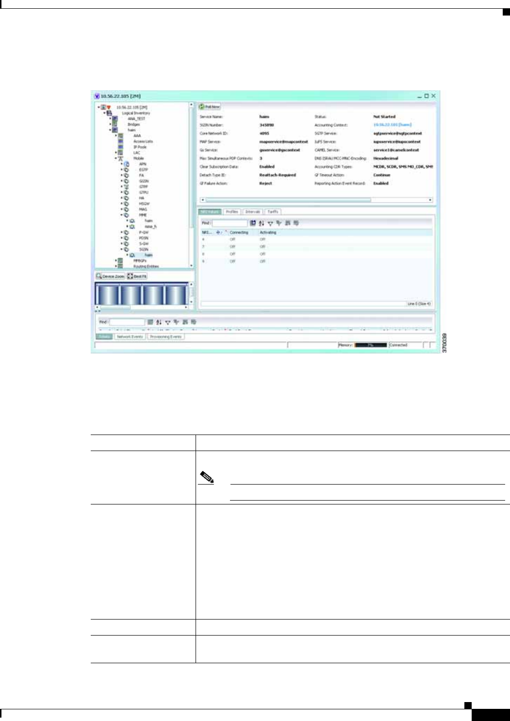
25-33
Cisco Prime Network 4.0 User Guide
OL-29343-01
Chapter 25 Monitoring Mobile Technologies GPRS/UMTS Networks
Step 2 In the logical inventory window, choose Logical Inventory > Context > Mobile > SGSN. The SGSN
services configured in Prime Network are displayed in the content pane as shown in the following figure.
Step 3 Under the SGSN node, choose an SGSN service. The SGSN service details are displayed in the content
pane.
Table 25-19 describes the SGSN service details.
Table 25-19 SGSN Service Details
Field Description
Service Name The unique name of the SGSN service.
Note You can configure only one SGSN service for a chassis.
Status The status of the SGSN service, which can be any of the following:
• Unknown
• Initiated
• Running
• Down
• Started
• Not Started
SGSN Number The phone number that is associated with the SGSN service.
Core Network ID The network code that identifies the core network tp connect the SGSN
service.

25-34
Cisco Prime Network 4.0 User Guide OL-29343-01
Chapter 25 Monitoring Mobile Technologies
GPRS/UMTS Networks
Associated SGTP
Service The name of the STGP service and its context associated to the SGSN
service. This service is represented in the following format:
<SGTP Service Name>@<SGTP Service Context>
Associated MAP
Service The name of the Mobile Application Part (MAP) service and its context that
is associated to the SGSN service. This service is represented in the
following format:
<MAP Service Name>@<MAP Service Context>
Note MAP is an SS7 protocol that provides an application layer for the
various nodes in GSM and UMTS mobile core networks and GPRS
core networks to communicate with each other in order to provide
services to mobile phone users. It is an application-layer protocol
used to access SGSN service.
Associated HSS Service The name of the Home Subscriber Server (HSS) service and its context that
is associated to the SGSN service. This service is represented in the
following format:
<HSS Service Name>@<HSS Service Context>
Associated IuPS
Service The name of the IuPS service and its context that is associated to the SGSN
service. This service is represented in the following format:
<IuPS Service Name>@<IuPS Service Context>
Note The interface between the RNC and the Circuit Switched Core
Network (CS-CN) is called Iu-CS and between the RNC and the
Packet Switched Core Network is called Iu-PS
Associated Gs Service The name of Gs service and its context that is associated to the SGSN
service. This service is represented in the following format:
<Gs Service Name>@<Service Context>
Associated CAMEL
Service The name of the Customized Application for Mobile Network Enhanced
Logic (CAMEL) service and its context. This service is represented in the
following format:
<CAMEL Service Name>@<CAMEL Context>
Max Simultaneous PDP
Contexts The maximum number of simultaneous Packet Data Protocl (PDP) contexts
per mobile station. This number can be any value between 2 and 11.
Offload T3312 Timeout The amount of time (in seconds) for sending period RAUs to the mobile
station. This time can be any value between 2 and 60.
Override LAC for LI The Location Area Code (LAC) that is associated with the SGSN service at
the time of record opening.
Override RAC for LI The Routing Area Code (RAC) that is associated with the SGSN service at
the time of record opening.
Table 25-19 SGSN Service Details (continued)
Field Description

25-35
Cisco Prime Network 4.0 User Guide
OL-29343-01
Chapter 25 Monitoring Mobile Technologies GPRS/UMTS Networks
Dns Israu
MCC-MNC-Encoding The format of the MCC and MNC values in the DNS query sent during the
Inter-SGSN RAU (ISRAU), which can be any one of the following:
• decimal
• hexadecimal
Accounting CDR Types The type of accounting Call Detail Record (CDR) configured for the SGSN
service, which can be any one of the following:
• MCDR
• SCDR
• SMS MO_CDR
• SMS MT_CDR
• SMBMSCDR
• LCS MT_CDR
• no accounting cdr-types
• Unknown
Multiple CDR types may be configured for a SGSN service. In such cases,
the types are separated by a comma and displayed here.
Clear Subscritpion Data Indicates whether the SGSN service will clear subscriber contexts and the
subscription database for the attached subscribers whenever the clear
subscribers all command is issued.
Detach Type IE The instruction that is included in the Detach-Request message during the
Admin-Disconnect procedure, which can be any one of the following:
• Reattach-Required
• Reattach-Not-Required
• Unknown
Gf Timeout Action The action to be taken by the SGSN service when a response is not received
from the Equipment Identify Register (EIR) even though a valid EIR
configuration exists under the MAP service and the route to the EIR is
available. Any one of the following actions is applicable:
• Continue
• Reject
Gf Failure Action The action to be taken by the SGSN service when the EIR is temporarily
inaccessible even though a valid EIR configuration exists under the MAP
service, which can be any one of the following:
• Continue
• Reject
Reporting Action Event
Record Indicates whether the SGSN service is allowed to enable GGM/SM event
logging for 3G services.
Table 25-19 SGSN Service Details (continued)
Field Description

25-36
Cisco Prime Network 4.0 User Guide OL-29343-01
Chapter 25 Monitoring Mobile Technologies
GPRS/UMTS Networks
Network Global MME
ID Management DB Indicates whether the SGSN service is associated to the Network Global
MMEID Management Database, which in turn is configured on the LTE
policy.
Tai Management DB Indicates whether the SGSN service is associated to the Tai Management
Database, which in turn is configured on the LTE policy.
NRI Values tab
NRI Value The MS assigned value of the Network Resource Identifier (NRI) to retrieve
from the P-TSMI, which is used to identify a SGSN service in a pool.
Note This value is unique across all pools.
Connecting Indicates whether the SGSN service will offload subscribers by sending
either a “Attach Request” or “RAU Request” message for the corresponding
NRI value.
Activating Indicates whether the SGSN service will offload subscribers by sending an
“Activate Request” message for the corresponding NRI value.
Profiles tab
Profile No. The type of billing,which can be any one of the following:
• 1—Hot billing
• 2—Flat billing
• 4—Prepaid billing
• 8—Normal billing
• All other profiles from 0-15 are customized billing types.
Buckets Denotes container changes in the Call Detail Record (CDR).
Down Link Octets The downlink traffic volume of the bucket.
Up Link Octets The uplink traffic volume of the bucket.
Total Octets The total traffic volume of the bucket.
Intervals tab
Prolfile No. The type of billing.
No. of SGSNs The number of changes to the SGSN (inter-SGSN switchovers) resulting in
a new Routing Area Identity (RAI) that can occur before closing an
accounting record.
Interval The amount of time (in seconds) that must elapse before closing an
accounting record.
Down Link Octets The downlink traffic volume reached within the time interval.
Up Link Octets The uplink traffic volume reached within the time interval.
Total Octets The total traffic volume reached within the time interval.
Tarrifs tab
Table 25-19 SGSN Service Details (continued)
Field Description

25-37
Cisco Prime Network 4.0 User Guide
OL-29343-01
Chapter 25 Monitoring Mobile Technologies GPRS/UMTS Networks
Viewing SGSN Service Properties
You can also view the following configuration details for SGSN service:
• GPRS Mobility Management—GPRS Mobility Management (GMM) is a GPRS signaling protocol
that handles mobility issues such as roaming, authentication, and selection of encryption algorithms.
GPRS Mobility Management, together with Session Management (GMM/SM) protocol support the
mobility of user terminal so that the SGSN can know the location of a mobile station (MS) at any
time and to activate, modify and deactivate the PDP sessions required by the MS for the user data
transfer. See GPRS Mobility Management Properties, page 25-37.
• NRI Properties—The Network Resource Identifier (NRI) identifies the specific CN node of the pool.
The UE derives the NRI from TMSI, P-TMSI, IMSI or IMEI. See NRI Properties, page 25-38.
• Session Management Properties—The SGSN service performs comprehensive session management,
including context activation, modification, deactivation, and preservation. It also provides support
for IPv4, IPv6, and PPP PDP context types. In addition, the SGSN's intelligent PDP context
preservation feature facilitates efficient radio resource utilization. See Session Management
Properties, page 25-39.
GPRS Mobility Management Properties
To view the GPRS Mobility Management details:
Step 1 Right-click the required device in Prime Network Vision and choose Inventory.
Step 2 In the logical inventory window, choose Logical Inventory > Context > Mobile > SGSN > GPRS
Mobility Management. The GPRS mobility details are displayed in the content pane.
Table 25-20 describes the SGSN service details.
Profile No. The type of billing.
Time (1 - 6) The time-of-day values at different times in a day, which is required to close
the current statistics container.
Table 25-19 SGSN Service Details (continued)
Field Description
Table 25-20 GPRS Mobility Management Details
Field Description
Max Identity Retries The maximum number of retransmissions allowed for identity requests. In
other words, it relates to the number of retransmissions allowed before
failure of the request. This number can be any value between 1 and 10.
Max Page Retries The maximum number of retransmissions allowed for page requests. In other
words, it relates to the number of retransmissions allowed before failure of
the request. This number can be any value between 1 and 5.
Max PTMSI Reloc
Retries The maximum number of retransmissions allowed for P-TMSI relocation
procedure. In other words, it relates to the number of retransmissions
allowed before failure of the P-TMSI relocation procedure. This number can
be any value between 1 and 10.

25-38
Cisco Prime Network 4.0 User Guide OL-29343-01
Chapter 25 Monitoring Mobile Technologies
GPRS/UMTS Networks
NRI Properties
To view the NRI Properties for an SGSN service:
Step 1 Right-click the required device in Prime Network Vision and choose Inventory.
Perform Identity After
Auth Indicates whether the SGSN service is allowed to perform an identity check
to ascertain the IMSI after an authentication failure on a P-TMSI message.
TRAU Timeout The amount of time (in seconds) that the SGSN service must wait to purge
the mobile stations’s data.This timer is started by the SGSN service after
completion of the inter-SGSN RAU.
T3302 Timeout The amount of time (in minutes) the SGSN service must wait to attach the
GPRS or RAU procedure on the mobile station node before retransmitting
the message again. This time can be any value between 1 and 186.
T3312 Timeout The amount of time (in minutes) the SGSN service must wait to initiate the
RAU procedure on the network network before retransmitting the message
again. This time can be any value between 1 and 186.
T3313 Timeout The amount of time (in seconds) the SGSN service must wait to initiate the
GPRS on the network before retransmitting the message again. This time can
be any value between 1 and 60.
T3322 Timeout The amount of time (in seconds) the SGSN service must wait to detach the
GPRS on the network before retransmitting the message again. This time can
be any value between 1 and 20.
T3350 Timeout The amount of time (in seconds) the SGSN service must wait to accept the
GPRS attach request, RAU attach request, or reallocation request sent with
the P-TSMI/TSMI on the network. This time can be any value between 1 and
20.
T3360 Timeout The amount of time (in seconds) the SGSN service must wait to guard the
authentication or cipher request on the network before retransmitting the
message again. This time can be any value between 1 and 20.
T3370 Timeout The amount of time (in seconds) the SGSN service must wait for the identity
request before retransmitting the message again. This time can be any value
between 1 and 20.
Mobile Reachable
Timeout The amount of time (in minutes) the SGSN service must wait to reach a
mobile station on the network before retransmitting the message again. This
time can be any value between 4 and 4400.
Implicit Detach
Timeout The amount of time (in seconds) the SGSN service must wait for the implicit
detach procedure on the network before retransmitting the message again.
This time can be any value between 1 and 3600.
Purge Timeout The amount of time (in minutes) the SGSN service must wait to detach the
mobility management context on the network before retransmitting the
message again. This time can be any value between 1 and 20160.
Table 25-20 GPRS Mobility Management Details (continued)
Field Description

25-39
Cisco Prime Network 4.0 User Guide
OL-29343-01
Chapter 25 Monitoring Mobile Technologies GPRS/UMTS Networks
Step 2 In the logical inventory window, choose Logical Inventory > Context > Mobile > SGSN > NRI
Properties. The NRI properties are displayed in the content pane.
Table 25-21 describes the NRI Properties details.
Session Management Properties
To view the Session Management properties for an SGSN service:
Step 1 Right-click the required device in Prime Network Vision and choose Inventory.
Step 2 In the logical inventory window, choose Logical Inventory > Context > Mobile > SGSN > Session
Management Properties. The Session Management properties are displayed in the content pane.
Table 25-22 describes the Session Management Properties details.
Table 25-21 NRI Properties Details
Field Description
NRI Length The number of bits to be used in P-TMSI to define the NRI, which can be
any number between 1 and 6. This length also determines the maximum size
of the pool. If you do not configure a length for the NRI, then the default
value of zero is considered to be the NRI’s length.
NRI Null Value The value of the null NRI, which is unique across all pool areas. If the NRI
null value is 0, it indicates that the keyword is not used. Any value between
1 and 63 is used to identify the SGSN service that is to be used for offloading
procedure for SGSN pooling.
Non Broadcast MCC The country code of the mobile, whic is basically the first part of the PLMN
ID. This code can be any value between 100 and 999.
Non Broadcast MNC The network code portion of the PLMN ID. This code must be a 2 or 3 digit
value between 1 and 999.
Non Broadcast LAC The location area code associated with an RNC. This code must be any value
between 1 and 65535.
Non Broadcast RAC The remote area code associated with an RNC. This code can be any value
between 1 and 255.
Table 25-22 Session Management Properties Details
Field Description
Max Activate Retries The maximum number of retries to activate PDP context, which can be any
value between 1 and 10.
Max Modify Retries The masimum number of retries to modify the PDP context, which can be
any value between 1 and 10.
Max Deactivate Retries The maximum number of retries to deactivate PDP context, which can be any
value between 1 and 10.

25-40
Cisco Prime Network 4.0 User Guide OL-29343-01
Chapter 25 Monitoring Mobile Technologies
LTE Networks
LTE Networks
These topics describe how to use Prime Network to monitor LTE networks and technologies:
• Overview of LTE Networks, page 25-40
• Working with LTE Network Technologies, page 25-41
Overview of LTE Networks
Long Term Evolution (LTE) is the latest step in moving forward from the cellular 3G services, such as
GSM to UMTS to HSPA to LTE or CDMA to LTE. LTE is based on standards developed by the Third
Generation Partnership Project (3GPP). LTE may also be referred more formally as Evolved UMTS
Terrestrial Radio Access Network (E-UTRAN). Following are the main objectives of an LTE network.
• Increased downlink and uplink peak data rates
• Scalable bandwidth
• Improved spectral efficiency
• All IP network
Figure 25-3 provides the topology of a basic LTE network.
T3385 Timeout The amount of time (in seconds) to wait for a network initiated activate
request before it is retransmitted again. This time can be any value between
1 and 60.
T3386 Timeout The amount of time (in seconds) to wait for a network initiated modify
request before it is retransmitted again. This time can be any value between
1 and 60.
T3395 Timeout The amount of time (in seconds) to wait for a network initiated deactivate
request before it is retransmitted again. This time can be any value between
1 and 60.
Guard Timeout The amount of time (in seconds) for retransmission of a GUARD request,
which can be any value between 1 and 60..
Table 25-22 Session Management Properties Details (continued)
Field Description
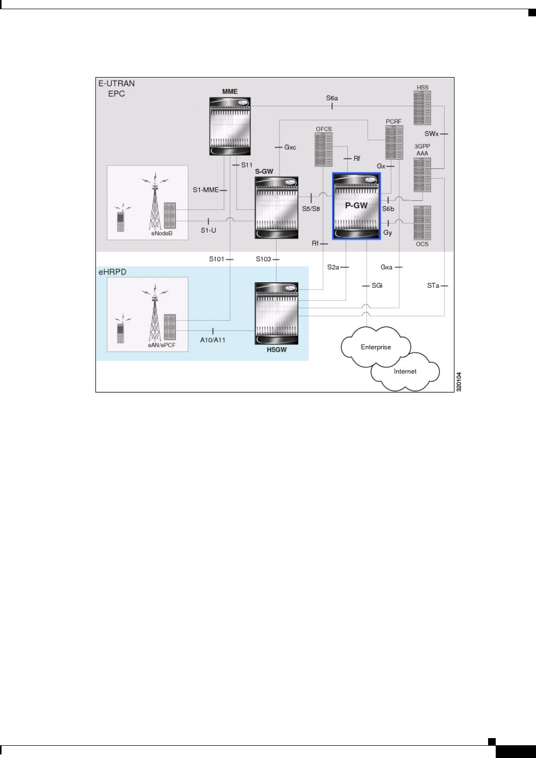
25-41
Cisco Prime Network 4.0 User Guide
OL-29343-01
Chapter 25 Monitoring Mobile Technologies LTE Networks
Figure 25-3 Basic LTE Network Topology
Working with LTE Network Technologies
The E-UTRAN uses a simplified single node architecture consisting of the eNodeBs (E-UTRAN
Node B). The eNB communicates with the Evolved Packet Core (EPC) using the S1 interface,
specifically with the Mobility Management Entity (MME) and Serving Gateway (S-GW) using S1-U
interface. The PDN Gateway (P-GW0 provides connectivity to the external packet data networks.
Following sections provide more details on these services and their support in Prime Network:
• Monitoring System Architecture Evolution Networks (SAE-GW), page 25-42
• Working with PDN-Gateways (P-GW), page 25-44
• Working with Serving Gateway (S-GW), page 25-46
• Viewing QoS Class Index to QoS (QCI-QoS) Mapping, page 25-48
• Viewing Layer 2 Tunnel Access Concentrator Configurations (LAC), page 25-49
• Monitoring the HRPD Serving Gateway (HSGW), page 25-53
• Monitoring Home Agent (HA), page 25-65
• Monitoring the Foreign Agent (FA), page 25-72
• Monitoring Evolved Packet Data Gateway (ePDG), page 25-83
• Monitoring Packet Data Serving Node (PDSN), page 25-92

25-42
Cisco Prime Network 4.0 User Guide OL-29343-01
Chapter 25 Monitoring Mobile Technologies
LTE Networks
• Viewing the Local Mobility Anchor Configuration (LMA), page 25-106
Monitoring System Architecture Evolution Networks (SAE-GW)
Systems Architecture Evolution (SAE) has a flat all-IP architecture with separation of control plane and
user plane traffic. The main component of SAE architecture is the Evolved Packet Core (EPC), also
known as SAE Core. The EPC serves as an equivalent to GPRS networks by using its subcomponents
Mobility Management Entities (MMEs), Serving Gateway (S-GW), and PDN Gateway (P-GW).
Mobility Management Entity (MME)
MME is the key control node for a Long Term Evolution (LTE) access network. It is responsible for idle
mode User Equipment (UE) tracking and paging procedure including retransmissions. It is involved in
the bearer activation/deactivation process and is also responsible for choosing the S-GW for a UE at the
initial attach and at time of intra-LTE handover involving Core Network (CN) node relocation. The
MME also provides the control plane function for mobility between LTE and 2G/3G access networks
with the S3 interface terminating at the MME from the SGSN. See
Serving Gateway (S-GW)
The S-GW routes and forwards user data packets, while also acting as the mobility anchor for the user
plane during inter-eNodeB handovers and as the anchor for mobility between LTE and other 3GPP
technologies. For idle state UEs, the S-GW terminates the downlink data path and triggers paging when
downlink data arrives for the UE. It manages and stores UE contexts, such as parameters of the IP bearer
service, network internal routing information, and so on. It also performs replication of the user traffic
in case of lawful interception. For more information, see Working with Serving Gateway (S-GW),
page 25-46.
PDN Gateway (P-GW)
The P-GW provides connectivity from the UE to external packet data networks by being the point of exit
and entry of traffic for the UE. A UE may have simultaneous connectivity with more than one P-GW for
accessing multiple PDNs. The P-GW performs policy enforcement, packet filtering for each user,
charging support, lawful interception, and packet screening. Another key role of the P-GW is to act as
the anchor for mobility between 3GPP and non-3GPP technologies such as WiMAX and 3GPP2. For
more information, see Working with PDN-Gateways (P-GW), page 25-44.
Running S-GW and P-GW services together as a SAE-GW provides the following benefits:
• Higher capacity—For a UE with one PDN connection that is passing through standalone S-GW and
P-GW services consumes 2 license units because both S-GW and P-GW services account for it
separately. SAE-GW as a single node consumes only one license unit for the same, thus increasing
the capacity.
• Cohesive configuration—Configuration and management of SAE-GW as a node is simpler to follow
and logical to explain.
See Viewing SAE-GW Properties, page 25-42 for details on how to view SAE-GW properties in Prime
Network Vision.
Viewing SAE-GW Properties
Prime Network Vision displays the SAE-GWs in a SAE-GW container under the Mobile node in the
logical inventory. The icon used for representing SAE-GW in the logical inventory is explained in
Logical Inventory Icons, page A-7.
To view SAE-GW properties:

25-43
Cisco Prime Network 4.0 User Guide
OL-29343-01
Chapter 25 Monitoring Mobile Technologies LTE Networks
Step 1 Right-click the required device in Prime Network Vision and choose Inventory.
Step 2 In the logical inventory window, choose Logical Inventory > Context > Mobile > SAE-GW Container.
Prime Network Vision displays the list of SAE-GW services configured under the container. You can
view the individual SAE-GW service details from the table on the right pane or by choosing Logical
Inventory > Context > Mobile > SAE-GW Container > SAE-GW.
Table 25-23 describes the details available for each SAE-GW.
SAE-GW Commands
The following commands can be launched from the inventory by right-clicking a SAE-GW and choosing
Commands > Configuration.
The table below lists the SAE-GW commands. Additional commands may be available for your devices.
New commands are often provided in Prime Network Device Packages, which can be downloaded from
the Prime Network software download site. For more information on how to download and install DPs
and enable new commands, see the information on “Adding Additional Device (VNE) support” in the
Cisco Prime Network 4.0 Administrator Guide.
Before executing any commands, you can preview them and view the results. If desired, you can also
schedule the commands. To find out if a device supports these commands, see the Cisco Prime Network
4.0 Supported Cisco VNEs.
Note You might be prompted to enter your device access credentials while executing a command. Once you
have entered them, these credentials will be used for every subsequent execution of a command in the
same GUI client session. If you want to change the credentials, click Edit Credentials. The Edit
Credentials button will not be available for SNMP commands or if the command is scheduled for a later
time.
Table 25-23 SAE-GW Properties in Logical Inventory
Field Description
Service Name Name of the SAE-GW service.
Service ID ID of the SAE-GW service.
Status Status of the SAE-GW service.
P-GW Service The P-GW service associated with the SAE-GW.
S-GW Service The S-GW service associated with the SAE-GW.
New Call Policy Specifies if the new call related behavior of SAE-GW service is enabled or
disabled, when duplicate sessions with same IP address request is received.

25-44
Cisco Prime Network 4.0 User Guide OL-29343-01
Chapter 25 Monitoring Mobile Technologies
LTE Networks
Working with PDN-Gateways (P-GW)
A PDN Gateway (P-GW) is the node that terminates the SGi interface towards the PDN. If a user
equipment (UE) is accessing multiple PDNs, there may be more than one P-GW for that UE. The P-GW
provides connectivity to the UE to external packet data networks by being the point of exit and entry of
traffic for the UE. A UE may have simultaneous connectivity with more than one P-GW for accessing
multiple PDNs.
The P-GW facilitates policy enforcement, packet filtering for each user, charging support, lawful
interception, and packet screening. The features of P-GW include:
• Integration of multiple core network functions in a single node
• Multiple instances of P-GW can enable call localization and local breakout
• High performance across all parameters like, signaling, throughput, density, and latency
• Integrated in-line services
• Support for enhanced content charging, content filtering with blacklisting, dynamic network-based
traffic optimization, application detection and optimization, stateful firewall, NAT translation, and
lawful intercept
• High-availability helps to ensure subscriber satisfaction
The following topics explain how to work with P-GW in Prime Network Vision:
• Viewing P-GW Properties, page 25-44
• P-GW Commands, page 25-45
Viewing P-GW Properties
Prime Network Vision displays the P-GWs in a P-GW container under the Mobile node in the logical
inventory. The icon used for representing P-GW in the logical inventory is explained in Logical
Inventory Icons, page A-7.
To view P-GW properties:
Step 1 Right-click the required device in Prime Network Vision and choose Inventory.
Step 2 In the logical inventory window, choose Logical Inventory > Context > Mobile > P-GW Container.
Prime Network Vision displays the list of P-GW services configured under the container. You can view
the individual P-GW service details from the table on the right pane or by choosing Logical
Inventory >Context > Mobile > P-GW Container > P-GW.
Table 25-25 describes the details available for each P-GW.
Table 25-24 SAE-GW Commands
Command Navigation Description
Create SAE GW Logical Inventory > Right-click on a
context > Commands > Configuration Use this command to create SAE
GW.
Delete SAE GW Right-click on a SAE
GW > Commands > Configuration Use this command to delete or
modify the configuration details for
a SAE GW.
Modify SAE GW

25-45
Cisco Prime Network 4.0 User Guide
OL-29343-01
Chapter 25 Monitoring Mobile Technologies LTE Networks
Step 3 If the P-GW is associated with PLMNs, you can view the details of the PLMNs on clicking the specified
P-GW.
P-GW Commands
The following commands can be launched from the inventory by right-clicking a P-GW and choosing
Commands > Configuration.
The table below lists the P-GW commands. Additional commands may be available for your devices.
New commands are often provided in Prime Network Device Packages, which can be downloaded from
the Prime Network software download site. For more information on how to download and install DPs
and enable new commands, see the information on “Adding Additional Device (VNE) support” in the
Cisco Prime Network 4.0 Administrator Guide.
Before executing any commands, you can preview them and view the results. If desired, you can also
schedule the commands. To find out if a device supports these commands, see the Cisco Prime Network
4.0 Supported Cisco VNEs.
Note You might be prompted to enter your device access credentials while executing a command. Once you
have entered them, these credentials will be used for every subsequent execution of a command in the
same GUI client session. If you want to change the credentials, click Edit Credentials. The Edit
Credentials button will not be available for SNMP commands or if the command is scheduled for a later
time.
Table 25-25 P-GW Properties in Logical Inventory
Field Description
Service Name Name of the P-GW service.
Service Status Status of the P-GW service.
EGTP Service Evolved GPRS Tunneling Protocol (EGTP) service associated with the
P-GW. EGTP provides tunneling support for the P-GW.
GGSN Service GGSN service associated with the P-GW.
LMA Service Local Mobility Anchor (LMA) that facilitates proxy mobile IP on the P-GW.
QCI QoS Mapping
Table Name Table name of QoS class indices that enfore QoS parameters.
New Call Policy Specifies if the new call related behavior of P-GW service is enabled or
disabled, when duplicate sessions with same IP address request is received.
Session Delete Delay
Timeout Duration, in seconds, to retain a session before terminating it.
SAE-GW Service Systems Architecture Evolution (SAE) gateway service associated with the
P-GW.

25-46
Cisco Prime Network 4.0 User Guide OL-29343-01
Chapter 25 Monitoring Mobile Technologies
LTE Networks
Working with Serving Gateway (S-GW)
In a Long Term Evolution (LTE) / Systems Architecture Evolution (SAE) network, a Serving Gateway
(S-GW) acts as a demarcation point between the Radio Access Network (RAN) and core network, and
manages user plane mobility. It serves as the mobility anchor when terminals move across areas served
by different eNode-B elements in Evolved UMTS Terrestrial Radio Access Network (E-UTRAN), as
well as across other 3GPP radio networks such as GSM EDGE Radio Access Network(GERAN) and
UTRAN. S-GW buffers downlink packets and initiates network-triggered service request procedures.
Other functions include lawful interception, packet routing and forwarding, transport level packet
marking in the uplink and the downlink, accounting support for per user, and inter-operator charging.
The S-GW routes and forwards user data packets, while also acting as the mobility anchor for the user
plane during inter-eNode-B handovers and as the anchor for mobility between LTE and other 3GPP
technologies.
For idle state user equipment (UE), the S-GW terminates the downlink data path and triggers paging
when downlink data arrives for the UE. It manages and stores UE contexts, such as parameters of the IP
bearer service, network internal routing information, and so on. It also performs replication of the user
traffic in case of lawful interception.
The following topics provide details on how to work with S-GWs in Prime Network Vision:
• Viewing S-GW Properties, page 25-46
• S-GW Commands, page 25-47
Viewing S-GW Properties
Prime Network Vision displays the S-GWs in a S-GW container under the Mobile node in the logical
inventory. The icon used for representing S-GW in the logical inventory is explained in Logical
Inventory Icons, page A-7.
To view S-GW properties:
Step 1 Right-click the required device in Prime Network Vision and choose Inventory.
Step 2 In the logical inventory window, choose Logical Inventory > Context > Mobile > S-GW Container.
Prime Network Vision displays the list of S-GW services configured under the container. You can view
the individual S-GW service details from the table on the right pane or by choosing Logical
Inventory >Context > Mobile > S-GW Container > S-GW.
Table 25-27 describes the details available for each S-GW.
Table 25-26 P-GW Commands
Command Navigation Description
Create P-GW PLMN Right-click on a
P-GW
service > Comm
ands > Configur
ation
Use this command to create a PLMN for
P-GW.
Delete P-GW Use this command to delete a P-GW.
Modify P-GW Use this command to modify the
configuration details for a P-GW.

25-47
Cisco Prime Network 4.0 User Guide
OL-29343-01
Chapter 25 Monitoring Mobile Technologies LTE Networks
Step 3 If the S-GW is associated with PLMNs, you can view the PLMN entries on clicking the specified S-GW.
S-GW Commands
The following commands can be launched from the inventory by right-clicking an S-W and choosing
Commands > Configuration.
The table below lists the S-GW commands. Additional commands may be available for your devices.
New commands are often provided in Prime Network Device Packages, which can be downloaded from
the Prime Network software download site. For more information on how to download and install DPs
and enable new commands, see the information on “Adding Additional Device (VNE) support” in the
Cisco Prime Network 4.0 Administrator Guide.
Before executing any commands, you can preview them and view the results. If desired, you can also
schedule the commands. To find out if a device supports these commands, see the Cisco Prime Network
4.0 Supported Cisco VNEs.
Table 25-27 S-GW Properties in Logical Inventory
Field Description
Service Name Name of the S-GW service.
Service Status Status of the S-GW service.
Accounting Context Name of the context configured on the system that processes accounting for
service requests handled by the S-GW service.
Accounting GTPP
Group Name of the accounting GTPP group associated with the S-GW service. This
will hold the configured GTPP server group (for GTPP servers redundancy)
on a S-GW service for CGF accounting functionality.
Accounting Mode Accounting protocol, which could be GTPP or Radius-Diameter.
Egress Protocol Egress protocol used for the S-GW service, which could be GTP, GTP-PMIP,
or PMIP.
Ingress EGTP Service Ingress EGTP service associated with the S-GW. EGTP provides tunneling
support for the S-GW.
Egress Context Context used for S-GW service egress.
Egress ETGP Service Ingress EGTP service associated with the S-GW. EGTP provides tunneling
support for the S-GW.
Egress Mag Service Mobile Access Gateway (MAG) egress service through calls are routed to
the S-GW.
IMS Authorization
Service IMS authorization service associated with the S-GW.
Accounting Policy Accounting policy configured for the S-GW.
New Call Policy Specifies if the new call related behavior of S-GW service is enabled or
disabled, when duplicate sessions with same IP address request is received.
QCI QoS Mapping
Table Table name of QoS class indices that enfore QoS parameters.
SAE GW Service Systems Architecture Evolution (SAE) gateway service associated with the
S-GW.

25-48
Cisco Prime Network 4.0 User Guide OL-29343-01
Chapter 25 Monitoring Mobile Technologies
LTE Networks
Note You might be prompted to enter your device access credentials while executing a command. Once you
have entered them, these credentials will be used for every subsequent execution of a command in the
same GUI client session. If you want to change the credentials, click Edit Credentials. The Edit
Credentials button will not be available for SNMP commands or if the command is scheduled for a later
time.
Viewing QoS Class Index to QoS (QCI-QoS) Mapping
The QoS Class Index (QCI) to QoS mapping configuration mode is used to map Dices to enforceable
QoS parameters. Mapping can occur between the RAN and the S-GW, the MME, and/or the P-GW in an
LTE network or between the RAN and the harped Serving Gateway (HSGW) in an eHRPD network. This
is a global configuration. These maps can be imported by P-gateway and S-gateway to enforce these
parameters on upstream/downstream traffic.
Prime Network Vision displays the QCI-QoS mapping information under the Mobile node in the logical
inventory. See Figure 25-18.
Note QCI-QoS mapping is applicable only for the ‘local’ context in the logical inventory.
To view QCI-QoS mapping:
Step 1 Right-click the required device in Prime Network Vision and choose Inventory.
Step 2 In the logical inventory window, choose Logical Inventory > local > Mobile > QCI-QoS Mapping.
Prime Network Vision displays the list of QCI-QoS mapping records configured under the container.
You can view the individual record from the table on the right pane or by choosing Logical
Inventory >Context > Mobile > QCI-QoS Mapping > Mapping Name.
Table 25-29 describes the QCI-QoS mapping details.
Table 25-28 S-GW Commands
Command Navigation Description
Create S-GW PLMN Right-click on a
S-GW service >
Commands >
Configuration
Use this command to create a PLMN for
S-GW.
Delete S-GW Use this command to delete a S-GW.
Modify S-GW Use this command to modify the
configuration details for a S-GW.
Table 25-29 QCI-QoS Mapping
Field Description
Mapping Name Name of the QCI-QoS mapping record.
QCI-QoS Mapping Table
QCI Number QCI number.
QCI Type QCI type.
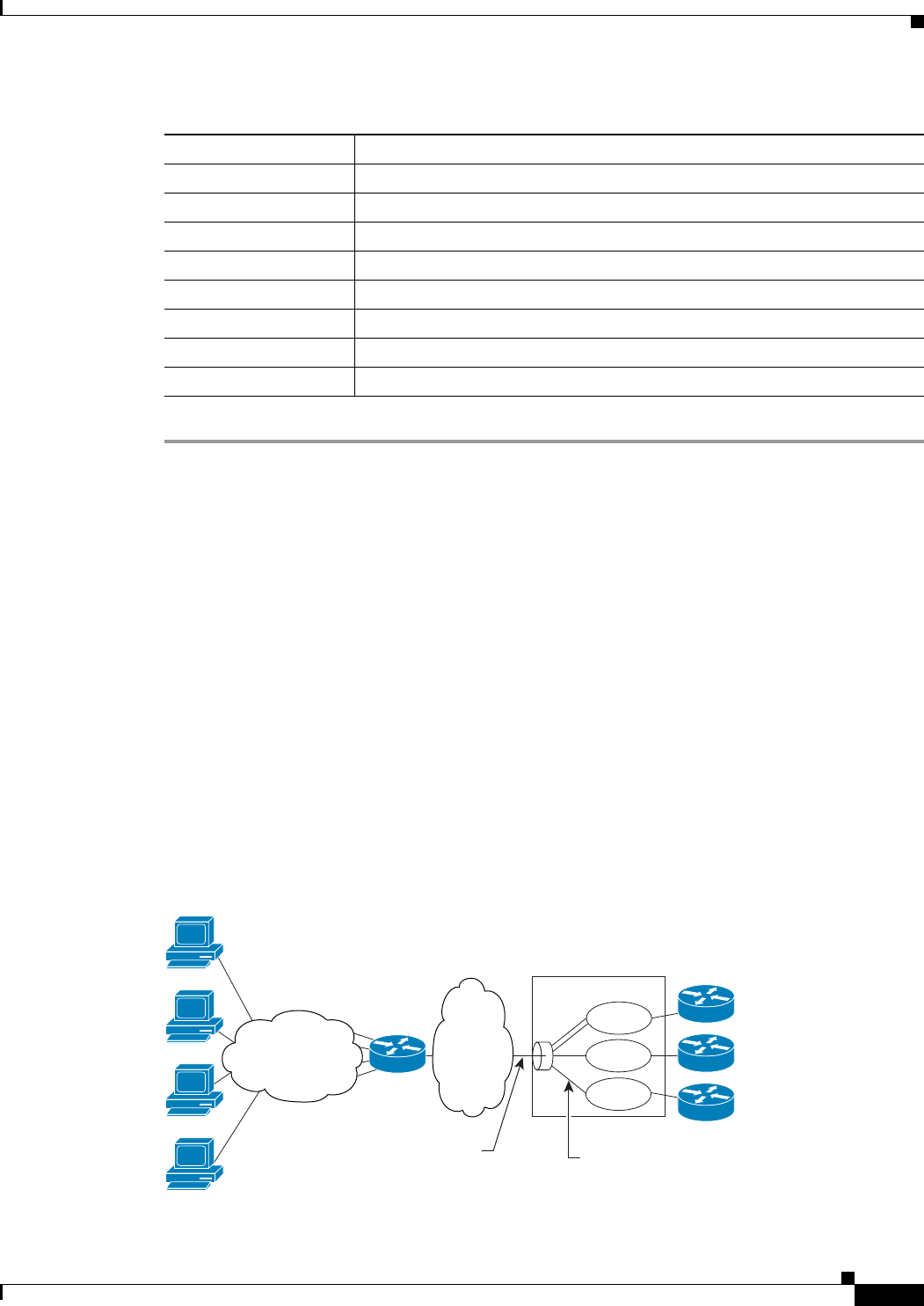
25-49
Cisco Prime Network 4.0 User Guide
OL-29343-01
Chapter 25 Monitoring Mobile Technologies LTE Networks
Viewing Layer 2 Tunnel Access Concentrator Configurations (LAC)
In computer networking, Layer 2 Tunneling Protocol (L2TP) is a tunneling protocol used to support
virtual private networks (VPNs) or as part of the delivery of services by ISPs. It does not provide any
encryption or confidentiality by itself; it relies on an encryption protocol that it passes within the tunnel
to provide privacy. The entire L2TP packet, including payload and L2TP header, is sent within a User
Datagram Protocol (UDP) datagram. It is common to carry Point-to-Point Protocol (PPP) sessions within
an L2TP tunnel.
The two endpoints of an L2TP tunnel are called the LAC (L2TP Access Concentrator) and the LNS
(L2TP Network Server). The LAC is the initiator of the tunnel while the LNS is the server, which waits
for new tunnels. Once a tunnel is established, the network traffic between the peers is bidirectional.
LAC allows users and telecommuters to connect to their corporate intranets or extranets using L2TP. In
other words, it forwards packets to and from the LNS and a remote system. It connects to the LNS using
a local area network or wide area network and directs subscriber sessions into L2TP tunnels based on
the domain of each session. Figure 25-4 denotes the LAC architecture.
Figure 25-4 LAC Architecture
Uplink DSCP marking to be used for encapsulation and UDP for uplink traffic
Downlink DSCP marking to be used for encapsulation and UDP for downlink traffic
Max Packet Delay Maximum packet delay, in milliseconds, that can be applied to the data.
Max Error Rate Maximum error loss rate of non congestion related packet loss.
Delay Class Packet delay.
Precedence Class Indicates packet precedence.
Reliability Class Indicates packet reliability.
Traffic Policing Interval Traffic policing interval.
Table 25-29 QCI-QoS Mapping (continued)
Field Description
CPE
PPP in L2TP
sessions
Retail LNS
provider
Provider 1
Provider 2
Provider n
320487
L2TP sessions
are terminated
and placed in a VRF
Wholesale LNS
provider
Cisco 10000 ESR
VRF 1
VRF n
VRF 2
LAC IP
transport
network
Access network
(ATM or Ethernet)
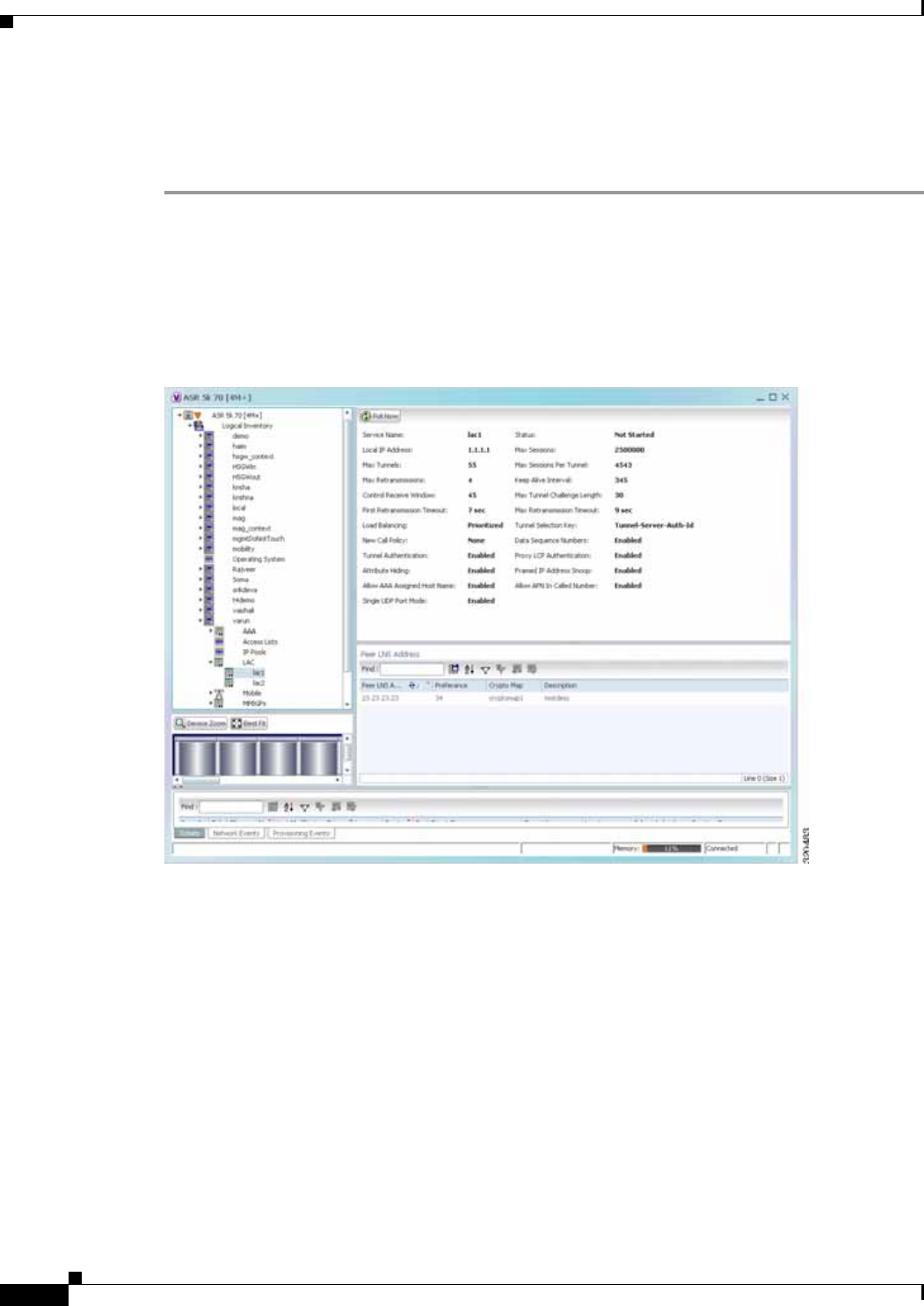
25-50
Cisco Prime Network 4.0 User Guide OL-29343-01
Chapter 25 Monitoring Mobile Technologies
LTE Networks
The packets that are exchanged within an L2TP tunnel can be categorized as control packets and data
packets.
To view the LAC configuration details:
Step 1 Right-click the required device in Prime Network Vision and choose Inventory.
Step 2 In the logical inventory window, choose Logical Inventory > Context > LAC. The list of LAC services
configured in Prime Network is displayed in the content pane.
Step 3 From the LAC node, choose an LAC service. The LAC service details are displayed in the content pane
as shown in Figure 25-5.
Figure 25-5 LAC Service Details
Table 25-30 displays the LAC configuration details.

25-51
Cisco Prime Network 4.0 User Guide
OL-29343-01
Chapter 25 Monitoring Mobile Technologies LTE Networks
Table 25-30 LAC Configuration Details
Field Description
Service Name The unique identification string for the LAC service.
Status The status of the LAC service, which can be any one of the following:
• Initiated
• Running
• Down
• Started
• Nonstarted
• Unknown
Local IP Address The local IP address bound with the LAC service.
Max Sessions The maximum number of subscribers connected to this service at any time,
which can be any value between 1 and 2500000. This field defaults to
2500000.
Max Tunnels The maximum length (in bytes) of the tunnel challenge.
Note The tunnel challenge is basically used to authenticate tunnels at the
time of creation.
Max Sessions Per
Tunnel The maximum number of sessions that can be handled by a single tunnel at
one point of time, which can be any value between 1 and 65535. This field
defaults to 512.
Max Retransmissions The maximum number of times a control message is retransmitted to a peer,
before clearing the tunnel and its sessions.
Keep Alive Interval The amount of time after which a keep alive message is sent.
Control Receive
Window The number of control messages the remote peer LNS can send before an
acknowledgement is received.
Max Tunnel Challenge
Length The maximum length (in bytes) of the tunnel challenge.
First Retransmission
Timeout The initial timeout before retransmitting a control message.
Note Each tunnel maintains a queue of control messages that must be
transmitted to its peer. If an acknowledgement is not received after
the specified period, then the control message is retransmitted.
Max Retransmission
Timeout The maximum amount of time between two retransmitted messages.
Load Balancing The type of load balancing to select LNS for the LAC service, which can be
any one of the following:
• Balanced
• Prioritized
• Random

25-52
Cisco Prime Network 4.0 User Guide OL-29343-01
Chapter 25 Monitoring Mobile Technologies
LTE Networks
Tunnel Selection Key The selection key to create tunnels between the L2TP service and the LNS
server, based on the value of the \u2015Tunnel-Server-Auth-ID\u2016
attribute received from the AAA server.
New Call Policy The new call policy for busy-out conditions, which can be any one of the
following:
• None
• Accept
• Reject
Data Sequence
Numbers Indicates whether data sequence numbering for sessions that use the current
LAC service is enabled. This option is enabled by default.
Tunnel Authentication Indicates whether tunnel authentication is enabled.
Note If this option is enabled, a configured shared secret is used to ensure
that the LAC service is communicating with an authorized peer LNS.
The shared secret is configured by the command in the LAC service
configuration mode, the command in the subscriber configuration
mode, or the Tunnel-Password attribute in the subscribers RADIUS
profile.
Proxy LCP
Authentication Indicates whether the option to send proxy LCP authentication parameters to
the LNS is enabled.
Attribute Hiding Indicates whether certain attributes in control messages sent from the LAC
to the LNS is hidden.
Note The LAC hides these attributes only if the tunnel authentication
option is enabled between the LAC and LNS.
Framed IP Address
Snoop Indicates whether the LAC can detect IPCP packets exchanged between the
mobile node and the LNS and extract the framed-I-address assigned to the
mobile node.
Note The address that is extracted is reported in the accounting start/stop
messages and will be displayed for each subscriber session.
Allow AAA Assigned
Host Name Indicates whether the Tunnel-Client-Auth ID assigned by AAA is used as the
Host name AVP in the L2TP tunnel setup message.
Note If the tunnel parameters are not received from the RADIUS server,
then the parameters configured in APN are considered for LNS peer
selection. When the parameters in APN are considered, the
local-hostname configured with the APN command for the LNS peer
is used as the LAC Host name.
Table 25-30 LAC Configuration Details
Field Description

25-53
Cisco Prime Network 4.0 User Guide
OL-29343-01
Chapter 25 Monitoring Mobile Technologies LTE Networks
Monitoring the HRPD Serving Gateway (HSGW)
The HRPD Serving Gateway (HSGW) is a component in the evolved High Rate Packet Data (eHRPD)
mobile network. It is an evolution option for CDMA operators that helps ensure converged mobility and
management between HRPD and LTE networks.
The HSGW terminates the eHRPD access network interface from the Evolved Access Network (eAN)
or Evolved Packet Core Function (ePCF) and routes UE-originated or terminated packet data traffic. It
provides interworking with the eAN/ePCF and the PDN Gateway (P-GW) within the Evolved Packet
Core (EPC) or LTE/SAE core network.
HSGW performs the following functions:
• Mobility anchoring for inter-eAN handoffs
• Transport level packet marking in the uplink and the downlink. For example, setting the DiffServ
Code Point, based on the QCI of the associated EPS bearer
• Uplink and downlink charging per UE, PDN, and QCI
• Downlink bearer binding based on policy information
• Uplink bearer binding verification with packet dropping of UL traffic that does not comply with
established uplink policy
• MAG functions for S2a mobility (i.e., Network-based mobility based on PMIPv6)
• Support for IPv4 and IPv6 address assignment
• EAP Authenticator function
• Policy enforcement functions defined for the Gxa interface
• Robust Header Compression (RoHC)
• Support for VSNCP and VSNP with UE
• Support for packet-based or HDLC-like framing on auxiliary connections
Allow APN in Called
Number Indicates whether the APN name in Called number AVP is sent as part of the
Incoming-Call Request (ICRQ) message sent to the LNS. If this keyword is
not configured, then the Called number AVP will not be included in the
ICRQ message sent to the LNS>
Single UDP Port Mode Indicates whether the standard L2TP port 1701 is used as a source port for
all L2TP control and data packets that originate from the LAC node.
Peer LNS Address
Peer LNS Address The IP address of the peer LNS for the current LAC service, which is usually
in standard IPv4 dotted decimal notation.
Preference The priority of the peer LNS, which can be any number between 1 and 128.
This priority is used when multiple peer LNS are configured.
Crypto Map The name of crypto map that is configured for the selected context.
Description The description of the specified peer LNS.
Table 25-30 LAC Configuration Details
Field Description
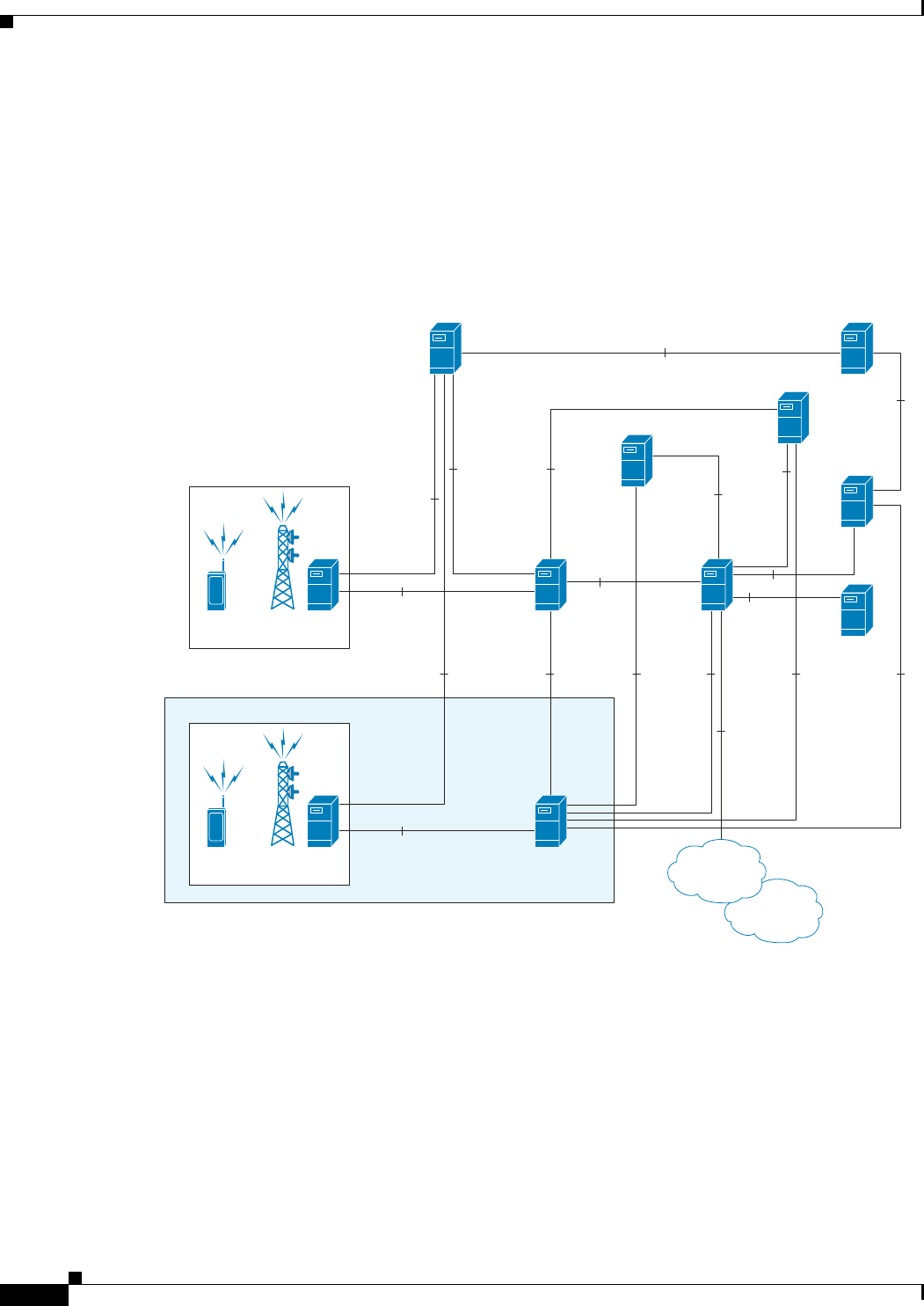
25-54
Cisco Prime Network 4.0 User Guide OL-29343-01
Chapter 25 Monitoring Mobile Technologies
LTE Networks
• IPv6 SLACC, generating RAs responding to RSs
An HSGW also establishes, maintains and terminates link layer sessions to UEs. The HSGW
functionality provides interworking of the UE with the 3GPP EPS architecture and protocols. This
includes support for mobility, policy control and charging (PCC), access authentication, and roaming.
The HSGW also manages inter-HSGW handoffs.
The topology of the HSGW network is shown in the following figure:
Figure 25-6 HSGW Topology
Basic Features of HSGW
The basic features supported by HSGW can be categorized as follows:
• Authentication
• IP Address Allocation
• Quality of Service
• AAA, Policy and Charging
eNodeB
S1-U
S-GW
S1-MME
S11
MME
MN
320490
PCRF
eANePCF
MN
eHRPD
S5/S8Gy
S6a
S6a
A10/A11
HSGW
S101 S103S2aSTa
SWx
SGi
Gxa
Gx
Rf
Rf
Gxc
3GPP
AAA
HSS
OCS
OFCS
P-GW
Internet
Enterprise

25-55
Cisco Prime Network 4.0 User Guide
OL-29343-01
Chapter 25 Monitoring Mobile Technologies LTE Networks
The Authentication features supported by HSGW are:
• EAP over PPP
• UE and HSGW negotiates EAP as the authentication protocol during LCP
• HSGW is the EAP authenticator
• EAP-AKA’ (trusted non-3GPP access procedure) as specified in TS 33.402
• EAP is performed between UE and 3GPP AAA over PPP/STa
The IP Address Allocation features supported by HSGW are:
• Support for IPv4 and IPv6 addressing
• Types of PDNs - IPv4, IPv6 or IPv4v6
• IPv6 addressing
–
Interface Identifier assigned during initial attach and used by UE to generate it’s link local
address
–
HSGW sends the assigned /64 bit prefix in RA to the UE
–
Configure the 128-bits IPv6 address using IPv6 SLAAC (RFC 4862)
–
Optional IPv6 parameter configuration via stateless DHCPv6(Not supported)
• IPv4 address
–
IPv4 address allocation during attach
–
Deferred address allocation using DHCPv4(Not supported)
–
Option IPv4 parameter configuration via stateless DHCPv4(Not supported)
The Quality of Service features supported by HSGW include:
• HRPD Profile ID to QCI Mapping
• DSCP Marking
• UE Initiated Dedicated Bearer Resource Establishment
• QCI to DSCP Mapping
The AAA, Policy and Charging features supported by HSGW include:
• EAP Authentication (STa)
• Rf Diameter Accounting
• AAA Server Groups
• Dynamic Policy and Charging: Gxa Reference Interface
• Intelligent Traffic Control
Viewing the HSGW Configuration
To view the HSGW configuration:
Step 1 Right-click the required device in Prime Network Vision and choose Inventory.
Step 2 In the logical inventory window, choose Logical Inventory > Context > Mobile > HSGW. The list of
HSGW services configured in Prime Network are displayed in the content pane.
Step 3 From the HSGW node, choose a HSGW service. The HSGW service details are displayed in the content
pane as shown in Figure 25-7.
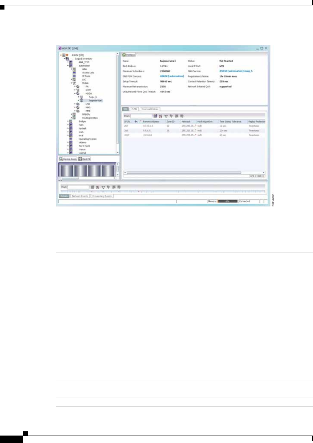
25-56
Cisco Prime Network 4.0 User Guide OL-29343-01
Chapter 25 Monitoring Mobile Technologies
LTE Networks
Figure 25-7 HSGW Service Details
Table 25-31 displays the HSGW service details.
Table 25-31 HSGW Service details
Field Description
Name The name of the HSGW service.
Status The status of the service, which can be any one of the following:
• Started
• Not Started
This field defaults to Not Started.
Bind Address The IPv4 address to which the service is bound to. This field defaults to Null
if binding is not done.
Local IP Port The User Datagram Protocol (UDG) port for the R-P interface of the IP
socket.
Maximum Subscribers The maximum number of subscriber sessions that the service can support.
MAG Service The Mobile Access Gateway (MAG) service associated with the HSGW
service. Clicking this link will take you to the relevant MAG service under
the MAG node.
DNS PGW Context The location of the Domain Name System (DNS) client, which is used to
identify the Fully Qualified Domain Name (FQDN) for the peer P-GW.
Registration Lifetime The registration lifetime that is configured for all the subscribers.

25-57
Cisco Prime Network 4.0 User Guide
OL-29343-01
Chapter 25 Monitoring Mobile Technologies LTE Networks
You can also view the following configuration details for a HSGW service:
Setup Timeout The maximum amount of time (in seconds) allowed for session setup.
Context Retention
Timeout The maximum number of time (in seconds) that the UE session context is
maintained by the HSGW service before it is torn down.
Note The UE session context includes the Link Control Protocol (LCP),
authentication and the A10 session context for a given UE.
Maximum
Retransmission The maximum number of times the HSGW service will try to communicate
with the eAN or PCF before it declares it as unreachable.
Network Initiated QoS Indicates whether the Network Initiated QoS feature is supported by the
HSGW service.
Unauthorized Flow QoS
Timeout The amount of time (in seconds) the service must wait before a QoS update
is triggered to downgrade an unauthorized flow.
SPI tab
SPI Number The unique Security Parameter Index (SPI) number, which indicates a
security context between the services.
Remote Address The IP address of the source service, which can be an IPv4 dotted decimal
notation or IPv6 colon separated notation.
Zone ID The PCF zone id that must be configured for the HSGW service.
Netmask The subnet mask of the service.
Hash Algorithm The hash algorithm used between the source and destination services.
Time Stamp Tolerance The difference (tolerance) in timestamps that is acceptable. If the actual
difference in the timestamps exceeds this difference, then the session is
rejected.
Replay Protection The replay-protection scheme that must be implemented by the service.
Description The description of the SPI.
PLMN tab
PLMN ID The unique id of the Public Land Mobile Network (PLMN), which is used to
determine if a mobile station is visiting, roaming, or belongs to the network.
Primary Indicates whether the PLMN Id must be used as the default and primary ID.
Overload Policies tab
IP Address The IP address of an alternate PDSN, which is in the IPv4 dotted decimal
notation.
Weight The weightage of the IP address, which determines the order in which the IP
address is used in case of multiple IP addresses.
Table 25-31 HSGW Service details (continued)
Field Description

25-58
Cisco Prime Network 4.0 User Guide OL-29343-01
Chapter 25 Monitoring Mobile Technologies
LTE Networks
• A10/A11 Properties—The A10/A11 interface (also known as R-P interface for RAN-to-PDSN)
supports the A10 protocol for user data transport between the PCF and PDSN, and the A11 protocol
for the associated signaling. A11 signaling messages are also used for passing accounting related
and other information from the PCF to the PDSN. The A10/A11 interfaces support mobility between
PCFs under the same PDSN. See Viewing the A10/A11 Configuration Details, page 25-58.
• GRE Parameters—Generic Routing Encapsulation (GRE) is a tunneling protocol developed by
Cisco Systems that can encapsulate a wide variety of network layer protocols inside virtual
point-to-point links over an Internet Protocol internetwork. See Viewing the GRE Parameters,
page 25-59.
• IP Source Violation—IP source violations occur when the PDSN receives packets from a subscriber
where the source address is not the same as the address given to the subscriber, and hence get
discarded. See Viewing the IP Source Violation Details, page 25-60.
Viewing the A10/A11 Configuration Details
To view the A10/A11 configuration details:
Step 1 Right-click the required device in Prime Network Vision and choose Inventory.
Step 2 In the logical inventory window, choose Logical Inventory > Context > Mobile > HSGW > HSGW
service > A10/A11 Properties. The configuration details are displayed in the content pane.
Table 25-32 displays the A10/A11 configuration details.
Table 25-32 A10 A11 Configuration Details
Field Description
Overload Policy The method used by the HSGW service to handle overload conditions, which
can be any one of the following:
• Reject
• Redirect
New Call Policy The new call policy configured for the HSGW service, which can be any one
of the following:
• None
• Reject
• Accept
This field defaults to None.
Data Available
Indicator Enabled Indicates whether the data available indicator in A10/A11 registration reply
messages is enabled.
Data Over Signalling Indicates whether the data over signaling marking feature for A10 packets is
enabled.
Airlink Bad Sequence The behavior for airlink related parameters configured for the HSGW
service, which can be any one of the following:
• Accept
• Deny

25-59
Cisco Prime Network 4.0 User Guide
OL-29343-01
Chapter 25 Monitoring Mobile Technologies LTE Networks
Viewing the GRE Parameters
To view the GRE Parameters for the HSGW service:
Step 1 Right-click the required device in Prime Network Vision and choose Inventory.
Step 2 In the logical inventory window, choose Logical Inventory > Context > Mobile > HSGW > HSGW
service > GRE Parameters. The relevant details are displayed in the content pane.
Table 25-33 displays the GRE parameter details.
Airlink Bad Sequence
Deny Code The reason for denying airlink bad sequence, which can be any one of the
following:
• Unsupported vendor ID
• Poorly formed request
Handoff With No
Connection Setup Indicates whether the HSGW service must accept or deny handoff R-P
sessions that do not have an Airlink Connection setup record in the A11
registration request.
RSVP Retransmission
Timeout The maximum amount of time (in seconds) in which RP control packets must
be retransmitted.
RSVP Maximum
Retransmission Count The maximum number of times the RP control packets can be retransmitted.
Table 25-32 A10 A11 Configuration Details (continued)
Field Description
Table 25-33 GRE Parameter Details
Field Description
Checksum Indicates whether insertion of GRE checksum in outgoing GRE data packets
is enabled.
Checksum Verify Indicates whether verification of GRE checksum in incoming GRE packets
is enabled.
Reorder Timeout The maximum amount of time (in milliseconds) to wait before reordered
out-of-sequence GRE packets are processed.
Sequence Mode The method to handle incoming out-of-sequence GRE packets, which can be
any one of the following:
• Reorder
• None
Sequence Numbers Indicates whether the option to insert or remove GRE sequence numbers in
GRE packets is enabled.
Flow Control Indicates whether flow control is supported by the selected HSGW service.
By default, this option is disabled.

25-60
Cisco Prime Network 4.0 User Guide OL-29343-01
Chapter 25 Monitoring Mobile Technologies
LTE Networks
Viewing the IP Source Violation Details
To view the IP source Violation configuration details:
Step 1 Right-click the required device in Prime Network Vision and choose Inventory.
Step 2 In the logical inventory window, choose Logical Inventory > Context > Mobile > HSGW > HSGW
service > IP Source Violation. The configuration details are displayed in the content pane.
Table 25-34 displays the IP Source Violation configuration details.
Flow Control Timeout The amount of time (in milliseconds) to wait for an Transmitter On (XON)
indicator from the RAN. This time can be any value between 1 and 1000000,
and defaults to 10000 milliseconds.
Flow Control Action The action that must be taken when the timeout limit is reached, which can
be any one of the following:
• disconnect-session
• resume-session.
Protocol Type The tunnel type for the GRE routing. This field defaults to Any.
Is 3GPP Extension
Header QoS Marking Indicates whether the 3GG Extension Header QoS Marking is enabled for
the selected HSGW feature.
Note If this feature is enabled and the PCF negotiation feature is enabled
in A11 RRQ, then the HSGW will include QoS optional data
attribute in the GRE 3GPP2 Extension Header.
MTU The maximum transmission unit (MTU) for packets accessing the APN.
IP Header DSCP The Differential Service Code Point (DSCP) value in the IP header that
marks the GRE IP Header encapsulation. This can be any value between
0x0F and 0X3F, and defaults to 0X0F.
IP Header DSCP Packet
Type Indicates whether the IP Header DSCP Value packet type is specified for the
packets, which can be any one of the following:
• all-control-packets—Indicates that DSCP marking for GRE IP header
encapsulation will be applied for all control packets for the session.
• setup-packets-only—Indicates that DSCP marking for GRE IP header
encapsulation willbe applied only for session setup packets.
GRE Segmentation Indicates whether segmentation of GRE packets is enabled. By default, this
option is disabled.
Table 25-33 GRE Parameter Details (continued)
Field Description

25-61
Cisco Prime Network 4.0 User Guide
OL-29343-01
Chapter 25 Monitoring Mobile Technologies LTE Networks
Configuration Commands for HSGW
The HSGW commands allow you to configure HSGW services in your network. Please note that these
commands are available only for Cisco ASR 5000 Mobile devices.
These commands can be launched from the logical inventory by choosing the
Context > Commands > Configuration or Context > Commands > Show.
Before executing any commands, you can preview them and view the results. If desired, you can also
schedule the commands.
The table below lists the HSGW commands. Additional commands may be available for your devices.
New commands are often provided in Prime Network Device Packages, which can be downloaded from
the Prime Network software download site. For more information on how to download and install DPs
and enable new commands, see the information on “Adding Additional Device (VNE) support” in the
Cisco Prime Network 4.0 Administrator Guide.
Note You might be prompted to enter your device access credentials while executing a command. Once you
have entered them, these credentials will be used for every subsequent execution of a command in the
same GUI client session. If you want to change the credentials, click Edit Credentials. The Edit
Credentials button will not be available for SNMP commands or if the command is scheduled for a later
time.
Table 25-35 lists the HSGW configuration commands.
Table 25-34 IP Source Violation Configuration Details
Field Description
Renegotiation Limit The number of source violations that are allowed within a specified detection
period, after which a PPP renegotiation is forced.
Drop Limit The number of source violations that are allowed within a specified detection
period, after which a call disconnect is forced.
Clear On Valid PDU Indicates whether the service must reset the renegotiation limit and drop
limit counters if a properly addressed packet is received.
Period The amount of time (in seconds) for the source violation detection period.
Once this value is reached, the drop limit and renegotiation limit counters are
decremented.
Table 25-35 HSGW Configuration Commands
Command Navigation Description
Create HSGW Right-click context > Commands >
Configuration Use this command to create a new
HSGW service.
Modify HSGW
Delete HSGW
Expand HSGW node > right-click HSGW
service > Commands > Configuration Use this command to modify/delete
the configuration details of an HSGW
service.
Show HSGW Expand HSGW node > right-click HSGW
service > Commands > Show Use this command to view and confirm
the configuration details of an HSGW
service.

25-62
Cisco Prime Network 4.0 User Guide OL-29343-01
Chapter 25 Monitoring Mobile Technologies
LTE Networks
Viewing the MAG Configuration for HSGW
A Mobile Access Gateway (MAG) performs mobility-related signaling on behalf of the mobile nodes
(MN) attached to its access links. MAG is the access router for the MN; that is, the MAG is the first-hop
router in the localized mobility management infrastructure
A MAG performs the following functions:
• Obtains an IP address from a Local Mobility Anchor (LMA) and assigns it to an MN
• Retains the IP address of an MN when the MN roams across MAGs
• Tunnels traffic from an MN to LMA
To view the MAG configuration details:
Create SPI Expand HSGW node > right-click HSGW
service > Commands > Configuration Use this command to create a new
Security Parameter Index (SPI) for the
HSGW service.
Modify SPI
Delete SPI
Expand HSGW node > HSGW service >
In content pane, click SPI tab >
right-click on SPI No. field > Commands
> Configuration
Use this command to modify/delete
the SPI configuration details for the
HSGW service.
Create PLMN
entries Expand HSGW node > right-click HSGW
service > Commands > Configuration Use this command to create a new
Public Land Mobile Network (PLMN)
for the HSGW service.
Modify PLMN
entries
Delete PLMN
entries
Expand HSGW node > HSGW service >
In content pane, click PLMN tab >
right-click on PLMN ID field >
Commands > Configuration
Use this command to modify/delete
the PLMN configuration details for the
HSGW service.
Create Overload
Policy Expand HSGW node > right-click HSGW
service > Commands > Configuration Use this command to create a new
overload policy for the HSGW service.
Modify Overload
Policy
Delete Overload
Policy
Expand HSGW node > HSGW service >
In content pane, click Overload Policies
tab > right-click on IP address field >
Commands > Configuration
Use this command to modify/delete
the overload policy details for the
HSGW service.
Modify A10 A11
Interface Expand HSGW node > HSGW service >
Right-click A10/A11 Properties >
Commands > Configuration
Use this command to modify the
A10/A11 configuration details for the
HSGW service.
Modify GRE Expand HSGW node > HSGW service >
right-click GRE > Commands >
Configuration
Use this command to modify the GRE
configuration details for the HSGW
service.
Modify IP Source
Violation Expand HSGW node > HSGW service >
right-click IP Source Violation >
Commands > Configuration
Use this command to modify the IP
source violation details for the HSGW
service.
Table 25-35 HSGW Configuration Commands (continued)
Command Navigation Description

25-63
Cisco Prime Network 4.0 User Guide
OL-29343-01
Chapter 25 Monitoring Mobile Technologies LTE Networks
Step 1 Right-click the required device in Prime Network Vision and choose Inventory.
Step 2 In the logical inventory window, choose Logical Inventory > Context > Mobile > MAG > MAG
service. The configuration details are displayed in the content pane.
Table 25-36 displays the configuration details for a MAG service.
Table 25-36 MAG Service Configuration Details
Field Description
Name The unique name of the MAG service.
Status The status of the MAG service, which can be any one of the following:
• Started
• Not Started
This field defaults to Not Started.
Bind Address The IP address to which the MAG service is bound to.
Maximum Subscribers The maximum number of subscribers supported by the service.
PMIP Maximum
Retransmission The maximum number of times the MAG service will communicate with the
LMA, before it is declared unreachable.
Registration Lifetime The registration lifetime configured for all the subscribers who have
subscribed to this service.
PMIP Retransmission
Timeout The maximum amount of time (in milliseconds) the MAG service must wait
for a response from the LMA.
PMIP Renewal Time Indicates the percentage of the registration lifetime when the registration
renewal is sent to the LMA for subscribers using this service.
PMIP Retransmission
Policy The retransmission policy for PMIP control messages, which can be any one
of the following:
• Normal
• Exponential backoff
New Call Policy The method for handling new calls, which can be any one of the following:
• Accept
• Reject
This field defaults to None.
PMIPv6 Tunnel
Encapsulation The encapsulation type used for PMIPv6 tunnel data between the MAG and
the LMA.
Information Set The mobility options to be used in Proxy Binding Update (PBU) messages,
for those messages sent between MAG and LMA.
Mobility Option Type The mobility option type used in the mobility messages.
Signalling Packets IP
Header DSCP The Differential Services Code Point (DSCP) value in the IP Header of the
signalling packets.

25-64
Cisco Prime Network 4.0 User Guide OL-29343-01
Chapter 25 Monitoring Mobile Technologies
LTE Networks
Viewing the Profile-QCI Mapping Details
You can view the configured mapping entries between a Rendezvous Point (RP) QoS Profile and the LTE
QoS Class Index (QCI).
A QCI is a scalar that is used as a reference to access node-specific parameters that control bearer level
packet forwarding treatment (e.g. scheduling weights, admission thresholds, queue management
thresholds, link layer protocol configuration, etc.), and that have been pre-configured by the operator
owning the access node.
To view the Profile-QCI mapping entries:
Step 1 Right-click the required device in Prime Network Vision and choose Inventory.
Step 2 In the logical inventory window, choose Logical Inventory > local > Mobile > Profile > Profile-QCI
Mapping > Profile-QCI Mapping. The mapping details are displayed in the content pane.
Table 25-37 displays the Profile-QCI Mapping details.
Configuration Commands for MAG
The MAG commands allow you to configure MAG services in your network. Please note that these
commands are available only for Cisco ASR 5000 Mobile devices.
These commands can be launched from the logical inventory by choosing the
Context > Commands > Configuration or Context > Commands > Show.
Before executing any commands, you can preview them and view the results. If desired, you can also
schedule the commands.
Table 25-37 Profile-QCI Mapping Details
Field Description
Profile Name The name of the Profile-QCI Mapping profile that is associated with the
HSGW.
Profile-QCI Mapping Table
QCI ID The QCI ID to which the profile is mapped.
Profile ID The profile ID to which the QCI ID is mapped.
Uplink GBR The Guaranteed Bit Rate (GBR) for the uplink data flow, which can be any
value between 0 and 4294967295.
Downlink GBR The GBR for the downlink data flow, which can be any value between 0 and
4294967295.
Uplink MBR The Maximum Bit Rate (MBR) for the uplink data flow, which can be any
value between 0 and 4294967295.
Downlink MBR The MBR for the downlink data flow, which can be any value between 0 and
4294967295.
Priority Level The priority level of the profile for the QCI, which can be any value between
1 and 15.
Preemption Capability The preemption capability of the profile.

25-65
Cisco Prime Network 4.0 User Guide
OL-29343-01
Chapter 25 Monitoring Mobile Technologies LTE Networks
The table below lists the MAG commands. Additional commands may be available for your devices.
New commands are often provided in Prime Network Device Packages, which can be downloaded from
the Prime Network software download site. For more information on how to download and install DPs
and enable new commands, see the information on “Adding Additional Device (VNE) support” in the
Cisco Prime Network 4.0 Administrator Guide.
Note You might be prompted to enter your device access credentials while executing a command. Once you
have entered them, these credentials will be used for every subsequent execution of a command in the
same GUI client session. If you want to change the credentials, click Edit Credentials. The Edit
Credentials button will not be available for SNMP commands or if the command is scheduled for a later
time.
Table 25-38 lists the MAG configuration commands.
Monitoring Home Agent (HA)
A Home Agent (HA) stores information about the mobile nodes whose permanent home address is in the
home agent’s network. When a node wants to communicate with the mobile node, it sends packets to the
permanent address. Because the home address logically belongs to the network associated with the HA,
normal IP routing mechanisms forward these packets to the home agent.
Table 25-38 MAG Configuration Commands
Command Navigation Description
Create MAG Right-click context > Commands >
Configuration Use this command to create a new
Mobile Access Gateway (MAG)
service for the selected context.
Modify MAG
Delete MAG
Expand MAG Node > right-click MAG
service > Commands > Configuration Use this command to modify the MAG
configuration details/delete the MAG
profile for the selected context.
Show MAG Expand MAG Node > right-click MAG
service > Commands > Show Use this command to view and confirm
the configuration details for the
selected MAG service.
Create Profile ID
QCI Mapping Right-click on context > Commands >
Configuration Use this command to create a QCI
profile.
Delete Profile ID
QCI Mapping Expand Profile node > right-click profile
name > Commands > Configuration Use this command to delete QCI
profile.
Create Profile Expand Profile node > right-click profile
name > Commands > Configuration Use this command to create an entry
for the QCI mapping profile.
Modify Profile
Delete Profile
Expand Profile node > profile >
right-click on profile entry >
Commands > Configuration
Use these commands to modify/delete
the entry for the QCI mapping profile.

25-66
Cisco Prime Network 4.0 User Guide OL-29343-01
Chapter 25 Monitoring Mobile Technologies
LTE Networks
When a mobile node moves out of the home network, the HA still manages to deliver the packets to the
mobile node. This is done by interacting with the Foreign Agent (FA) that the mobile node is
communicating with using the Mobile IP (MIP) Standard. Such transactions are performed through the
use of virtual private networks that create MIP tunnels between the HA and FA. The following figure
displays the configuration between the FA and HA network deployment.
Figure 25-8 Home Agent Topology
When functioning as a HA, the system can either be located within the carrier’s 3G network or in an
external enterprise or ISP network. The FA terminates the mobile subscriber’s PPP session, and then
routes data to and from the appropriate HA on behalf of the subscriber.
In accordance with Request for Comments (RFC) 2002, the FA is responsible for mobile node
registration with, and tunneling of data traffic from/to the subscriber’s home network. The HA is also
responsible for tunneling traffic, but it maintains subscriber location information separately in the
Mobility Binding Records (MBR).
Viewing the Home Agent Configuration
To view the Home Agent configuration:
Step 1 Right-click the required device in Prime Network Vision and choose Inventory.
Step 2 In the logical inventory window, choose Logical Inventory > Context > Mobile > Home Agent. The
list of home agent services configured in Prime Network are displayed in the content pane.
Step 3 From the Home Agent node, choose a home agent service. The home agent service details are displayed
in the content pane as shown in Figure 25-9.
Radio
Tower BSC/PCFMN
320490
PDSN/FA
Foreign AAA
AAA AAA
R-P P1 P1 PDN
HA CN
Home AAA
IP Network Internet
or PDN
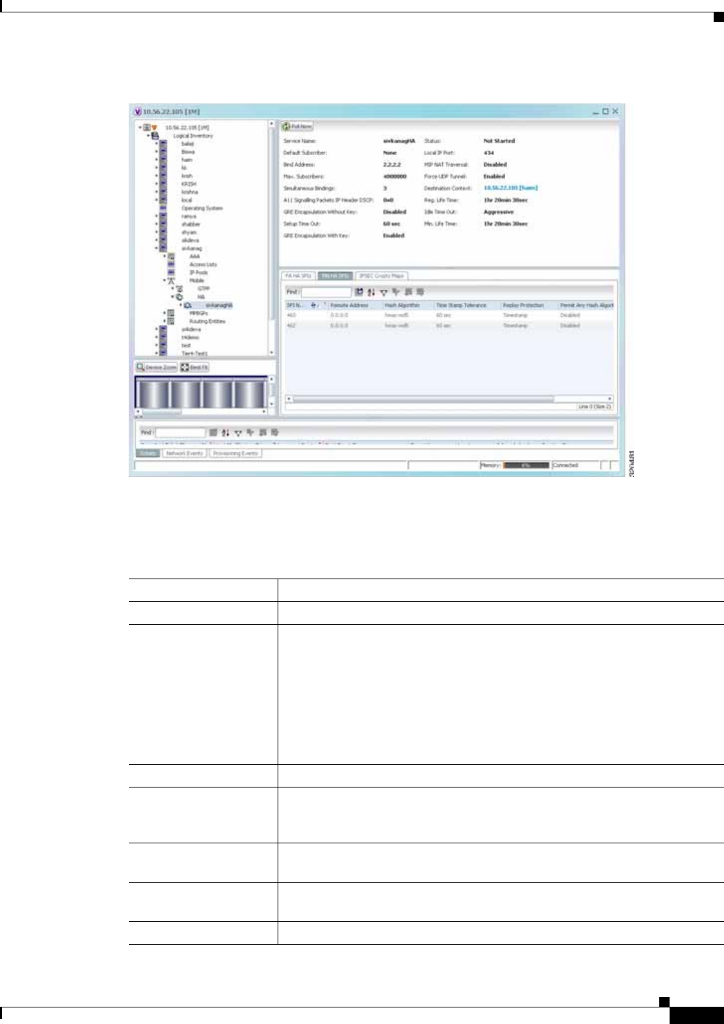
25-67
Cisco Prime Network 4.0 User Guide
OL-29343-01
Chapter 25 Monitoring Mobile Technologies LTE Networks
Figure 25-9 Home Agent Service Details
Table 25-39 displays the Home Agent service details.
Table 25-39 Home Agent Service Details
Field Description
Service Name The name of the home agent service.
Status The status of the home agent service, which can be any one of the following:
• Down
• Running
• Initiated
• Unknown
This field defaults to Down.
Default Subscriber The name of the subscriber template that is applied to the subscribers.
Local IP Port The User Datagram Protocol (UDP) port for the R-P interface of the IP
socket. This IP port can be any value between 1 and 65535 and defaults to
699.
Bind Address The IP address to which the service is bound to. This can be any address in
the IPV4/IPv6 range.
MIP NAT Traversal Indicates whether the acceptance of UDP tunnels for NAT traversal is
enabled.
Max. Subscribers The maximum subscriber sessions that could be supported.

25-68
Cisco Prime Network 4.0 User Guide OL-29343-01
Chapter 25 Monitoring Mobile Technologies
LTE Networks
Force UDP Tunnel Indicates whether HA would accept requests when Network Address
Translation (NAT) is not detected but the Force bit is set in the Registration
Request (RRQ) with the UDP Tunnel Request.
Simultaneous Bindings The maximum number of care of addresses that can be simultaneously bound
for the same user identified by Network Access Identifier (NAI) and Home
address.
Destination Context The name of the context to assign to the subscriber, after authentication.
A11 Signalling Packets
IP Header DSCP The Differential Services Code Point (DSCP) value in the IP header.
Registration Life Time The registration lifetime configured for all the subscribers to the service.
GRE Encapsulation
Without Key Indicates whether Generic Routing Encapsulation (GRE) without
encapsulation key is used during Mobile IP sessions with FA.
Idle Time Out The method the HA service uses to determine the time to reset a session idle
timer, which can be any one of the following:
• Aggressive
• Handoff
• Normal
SPI List The Security Parameter Index (SPI) between the HA service and the FA.
Optimize Tunnel
Reassembly Indicates whether the option to optimize tunnel reassembly is enabled.
Wi-Max 3GPP Indicates whether the Worldwide Interoperability for Microwave Acces
(Wi-Max)-3GPP option is enabled for the Home agent service.
Setup Time Out The maximum time (in seconds) allowed for session setup.
Reverse Tunnel Indicates whether reverse tunnel feature is enabled for the home agent
feature.
Note A reverse tunnel is a tunnel that starts at the care-of address of the
mobile node and terminates at the home agent. A mobile node can
request a reverse tunnel between the foreign agent and the home
agent when the mobile node registers.
Min. Life Time The minimum registration life time for a mobile IP session.
GRE Encapsulation
With Key Indicates whether GRE is used during mobile IP sessions with an FA.
FA HA SPIs / MN HA SPIs tab
SPI Number The number to indicate the security context between services.
Remote Address The IP address of the source service.
Hash Algorithm The hash algorithm used between the source and destination services.
Time Stamp Tolerance The acceptable allowable difference in time stamps. If this difference is
exceeded, then the session is rejected.
Replay Protection The replay protection scheme that should be implemented by the service.
Table 25-39 Home Agent Service Details (continued)
Field Description

25-69
Cisco Prime Network 4.0 User Guide
OL-29343-01
Chapter 25 Monitoring Mobile Technologies LTE Networks
Viewing the AAA Configuration for Home Agent Service
In order to support Packet Data Serving Node (PDSN), FA, and HA functionality, the system must be
configured with at least one source context and at least two destination contexts as shown in the
following figure.
The source context will facilitate the PDSN service(s), and the R-P interfaces. The AAA context will be
configured to provide foreign/home AAA functionality for subscriber sessions and facilitate the AAA
interfaces.
To view the AAA configuration:
Step 1 In the logical inventory window, choose Logical Inventory > Context > Mobile > Home Agent >
Home agent service > AAA. The AAA configuration details are displayed in the content pane.
Table 25-40 displays the AAA configuration for a home agent service.
Permit Any Hash
Algorithm Indicates whether verification of MN-HA authenticator using other hash
algorithms is allowed, on failure of the configured hash algorithm.
Note This field is available only in the MN HA SPIs tab.
Description The description of the SPI.
IPSEC Crypto Maps
Map Name The name of the crypto map that is configured in the same context that
defines the IPSec tunnel properties.
Peer FA Address The IP address of the Peer FA to which the IPSEC SA will be established.
Skey Expiry The expiry information of the secret key.
Table 25-39 Home Agent Service Details (continued)
Field Description
Table 25-40 AAA Configuration for Home Agent Service
Field Description
AAA Context The AAA context for the home agent service. Click this link to view the
relevant AAA context.
AAA Accounting Indicates whether the Home Agent can send AAA accounting information
for subscriber sessions.
AAA Accounting
Group The AAA Accounting group for the Home agent service.
AAA Distributed MIP
Keys Indicates the usage of AAA distributed MIP keys for authenticating RRQ for
WiMax HA calls.
DMU Refresh Key Indicates whether the Home Agent is allowed to retrieve the MN-HA key
again from the AAA during the call and use this freshly retrieved key value
to recheck authentication.
IMSI Authentication Indicates whether MN-AAA or MN-FAC extensions are present in the RRQ.

25-70
Cisco Prime Network 4.0 User Guide OL-29343-01
Chapter 25 Monitoring Mobile Technologies
LTE Networks
Viewing the GRE Configuration for Home Agent Service
To view the GRE configuration:
Step 1 In the logical inventory window, choose Logical Inventory > Context > Mobile > Home Agent >
Home agent service > GRE. The GRE configuration details are displayed in the content pane.
Table 25-41 displays the GRE configuration for a home agent service.
Viewing the Policy Configuration for Home Agent Service
To view the Policy configuration:
Step 1 In the logical inventory window, choose Logical Inventory > Context > Mobile > Home Agent >
Home agent service > Policy. The Policy configuration details are displayed in the content pane.
MN HA Authentication
Type Indicates whether the HA service looks for an MN-HA authentication in the
RRQ.
MN AAA
Authentication Type The method used to send authentication request to AAA for each
re-registration attempt.
Note The initial registration request and de-registrations are handled
normally.
PMIP Authentication Indicates whether the HA service looks for an PMIP authentication in the
RRQ.
Stale Key Disconnect Indicates whether the call must be disconnected immediately on failure of
MN-HA authentication.
Skew Lifetime The IKE pre-shared key\u2018s time skew.
Table 25-40 AAA Configuration for Home Agent Service (continued)
Field Description
Table 25-41 GRE Configuration for Home Agent Service
Field Description
Checksum Indicates whether insertion of GRE checksum in outgoing GRE data packets
is enabled.
Checksum Verify Indicates whether verification of GRE checksum in incoming GRE packets
is enabled.
Reorder Timeout The maximum amount of time (in milliseconds) to wait before reordered
out-of-sequence GRE packets are processed.
Sequence Mode The method to handle incoming out-of-sequence GRE packets, which can be
any one of the following:
• Reorder
• None
Sequence Numbers Indicates whether the option to insert or remove GRE sequence numbers in
GRE packets is enabled.

25-71
Cisco Prime Network 4.0 User Guide
OL-29343-01
Chapter 25 Monitoring Mobile Technologies LTE Networks
Table 25-42 displays the Policy configuration for a home agent service.
Viewing the Registration Revocation Details for a Home Agent Service
To view the Registration revocation configuration details:
Step 1 In the logical inventory window, choose Logical Inventory > Context > Mobile > Home Agent >
Home agent service > Registration Revocation. The configuration details are displayed in the content
pane.
Table 25-43 displays the Registration Revocation configuration for a home agent service.
Table 25-42 Policy Configuration for Home Agent Service
Field Description
BC Response Code The response code for a binding cache (BC) query result in response to a
network failure or error.
NW-Reachability
Policy The action to be taken on detection of an upstream network-reachability
failure.
Over Load Policy The overload policy within the HA service.
New Call Policy The new call policy within the HA service.
Over Load Redirect / NW-Reachability Redirect
IP Address The IP address associated with the policy.
Weight The weightage of the IP address associated with the policy.
Table 25-43 Registration Revocation configuration for Home Agent Service
Field Description
Registration Revocation
State Indicates whether the Registration Revocation Status is enabled.
Revocation IBit Indicates whether the Revocation Ibit feature is enabled.
Send NAI Extension Indicates whether the option to send NAI extension in the revocation
message is enabled.
Handoff Old FA Indicates whether the option to send a revocation message from the HA to
the FA is enabled.
Note The revocation message is sent from the HA to the FA when an
inter-access gateway or FA handoff of the MIP session occurs.
Idle Timeout Indicates whether the HA must send a revocation message to the FA when
the session times out.
Revocation Max Retries The number of times the revocation message can be retransmitted.
Revocation Timeout The maximum amount of time (in seconds) to wait for the receipt of an
acknowledgement from the FA before the revocation message is transmitted
again.

25-72
Cisco Prime Network 4.0 User Guide OL-29343-01
Chapter 25 Monitoring Mobile Technologies
LTE Networks
Monitoring the Foreign Agent (FA)
A Foreign Agent (FA) is basically a router on a mobile node’s visited network that provides routing
services to the mobile node. The FA acts as a mediator between the mobile node and it’s home agent
(HA). When the mobile node moves out of its home network, the FA registers the mobile node with a
Care of Address (CoA). It also facilitates routing information to the mobile node’s home agent, which
contains the permanent address of the node.
When a node tries to communicate with a mobile node that is roaming, it sends packets to the permanent
address. The HA interacts with the FA and delivers the packets to the mobile node using the COA.
Figure 25-10 depicts the function of a foreign agent in a network and the different components that it
interacts with.
Figure 25-10 Foreign Agent Architecture
Viewing the Foreign Agent Configuration Details
To view the Foreign Agent configuration details:
Step 1 Right-click the required device in Prime Network Vision and choose Inventory.
Step 2 In the logical inventory window, choose Logical Inventory > Context > Mobile > FA. The list of
Foreign agents configured in Prime Network are displayed in the content pane.
Step 3 From the FA node, choose a FA service. The FA service details are displayed in the content pane as
shown in Figure 25-11.
Radio
Tower
Radio Access Network (RAN)
BSC/PCFMN
320489
PDSN/FA
PPP
Foreign AAA
R-P Interface
HA CN
Home AAA
Internet
or PDN
IP in IP or GRE Tunnel
IP
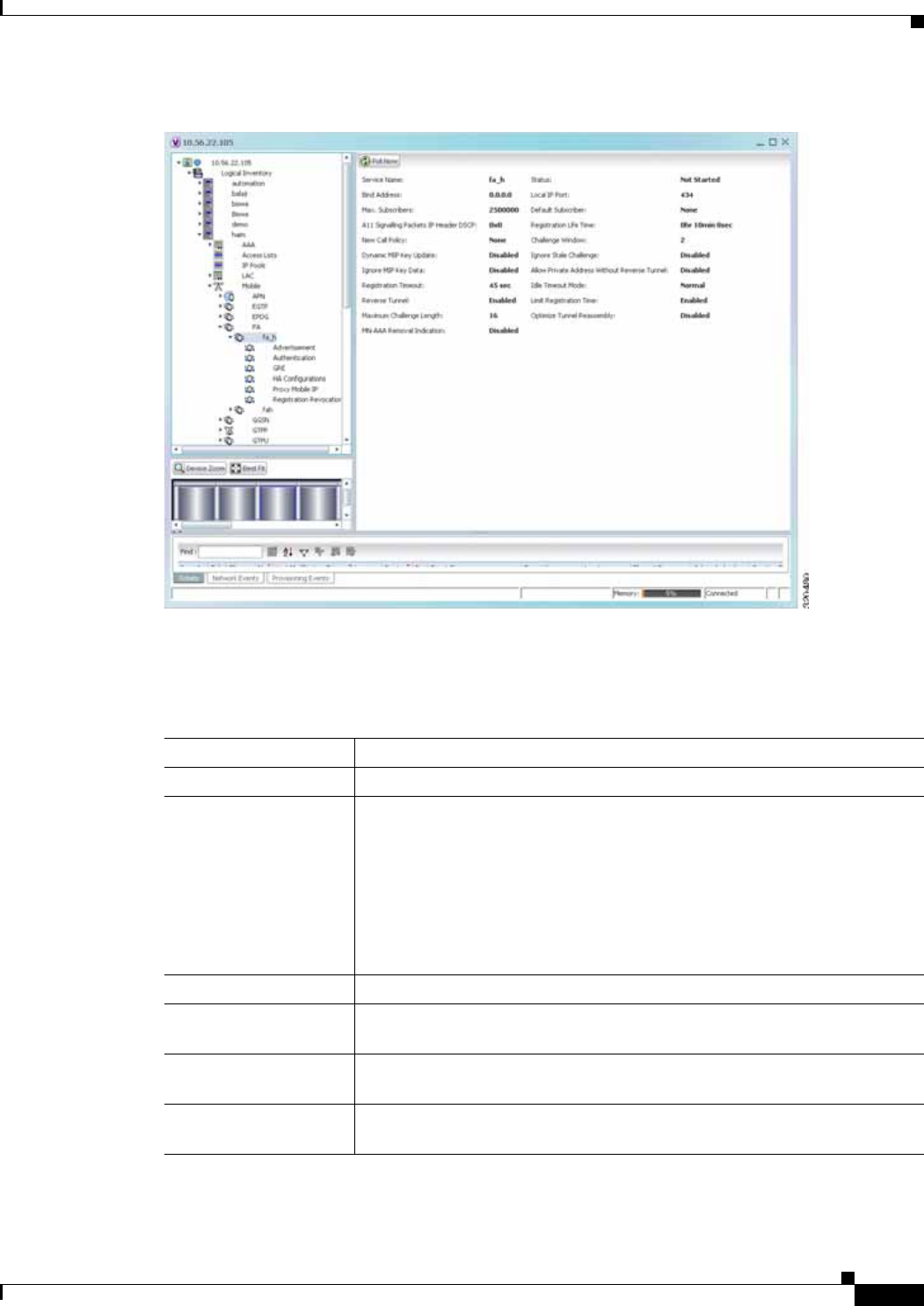
25-73
Cisco Prime Network 4.0 User Guide
OL-29343-01
Chapter 25 Monitoring Mobile Technologies LTE Networks
Figure 25-11 Foreign Agent Service Details
Table 25-44 displays the Foreign Agent configuration details.
Table 25-44 FA Configuration Details
Field Description
Service Name The unique name to identify the FA service.
Status The status of the FA service, which can be any one of the following:
• Down
• Running
• Initiated
• Unknown
This field defaults to Down.
Bind Address The IPv4 address to which the service is bound.
Local IP Port The UDP port for the R-P Interface of the IP socket. This port can be any
value between 1 and 65535, and defaults to 434.
Max. Subscribers The maximum subscriber sessions that is supported by the service. This can
be any value between 0 and 2500000, and defaults to 2500000.
Default Subscriber The name of the subscriber template that is applicable to the subscribers
using this domain alias.

25-74
Cisco Prime Network 4.0 User Guide OL-29343-01
Chapter 25 Monitoring Mobile Technologies
LTE Networks
A11 Signalling Packets
IP Header DSCP The Differential Service Code Point (DSCP) value in the IP header. This
value can range between 0x0 and 0x3F, and defaults to 0x0F.
Note The Differentiated Services (DS) field of a packet contains 6 bits that
represents the DSCP value. Out of these 6 bits, five of them represent
the DSCP. Hence, you can assign upto 32 DSCPs for various
priorities.
Registration Life Time The amount of time (in seconds) that an A10 connection can exist before its
registration expires. This time can be any value between 1 and 65534, and
defaults to 1800 seconds.
New Call Policy The call policy for one or all the services, which can be any one of the
following:
• Reject
• None
This field defaults to None.
Challenge Window The number of challenges that can be handled by the FA.
Dynamic MIP Key
Update The status of the Dynamic Mobile IP Key update feature. This option is
disabled by default.
Ignore Stale Challenge The status of the Ignore Stale Challenge in MIP RRQ. This option is disabled
by default.
Ignore MIP Key Data The status of the Ignore MIP Key data. This option is disabled by default.
Allow Private Address
Without Reverse Tunnel Indicates whether the mobile node can use reverse tunnel for a private
address. This option is disabled by default.
Registration Timeout The amount of time (in seconds) for the registration reply timeout.
Idle Timeout Mode The idle timeout method, which can be any one of the following:
• Normal
• Aggressive
Reverse Tunnel Indicates whether reverse tunneling is applicable for client mobile IP
sessions. This option is enabled by default.
Limit Registration Time Indicates whether MIP registration lifetime is shorter than session idle,
absolute, and long-duration timeouts. By default, this option is enabled.
Maximum Challenge
Length The maximum length of the FA challenge.
Optimize Tunnel
Reassembly Indicates whether tunnel reassembly is optimized for fragmented large
packets passed between HA and FA. By default, this option is disabled.
MN-AAA Removal
Indication Indicates whether the FA can remove MN-FAC and MN-AAA extensions
from RRQs. By default, this option is disabled.
Table 25-44 FA Configuration Details (continued)
Field Description

25-75
Cisco Prime Network 4.0 User Guide
OL-29343-01
Chapter 25 Monitoring Mobile Technologies LTE Networks
You can also view the following configuration details for a Foreign Agent service:
• Advertisement—Foreign agents advertise their presence on their attached links by periodically
multicasting or broadcasting messages called agent advertisements. Mobile nodes listen to these
advertisements and determine if they are connected to their home link or foreign link. Rather than
waiting for agent advertisements, an MN can also send an agent solicitation. This solicitation forces
any agents on the link to immediately send an agent advertisement.
• Authentication—Authentication verifies users before they are allowed access to the network and
network services.
• GRE—Generic routing encapsulation (GRE) is a tunneling protocol used by Mobile IP. The GRE
tunnel interface creates a virtual point-to-point link between two routers at remote points over an IP
internetwork. If the GRE for Cisco Mobile Networks feature is enabled, the mobile router will
request GRE encapsulation in the registration request only if the FA advertises that it is capable of
GRE encapsulation (the G bit is set in the advertisement). If the registration request is successful,
packets will be tunneled using GRE encapsulation. If the GRE for Cisco Mobile Networks feature
is enabled and the mobile router is using collocated care-of address (CCoA), the mobile router will
attempt to register with the HA using GRE encapsulation. If the registration request is successful,
packets will be tunneled using GRE encapsulation.
• HA Configurations—Once the mobile node roams to a new network, it must register with the home
agent as being away from home. Its registration is sent by way of the Foreign Agent (FA), the router
providing service on the foreign network. A security association between the home agent (HA) and
the foreign agent (FA) is mandatory.
• Proxy Mobile IP—Proxy Mobile IP supports Mobile IP for wireless nodes without requiring
specialized software for those devices. The wireless access point acts as a proxy on behalf of
wireless clients that are not aware of the fact that they have roamed onto a different Layer 3 network.
The access point handles the IRDP communications to the foreign agent and handles registrations
to the home agent.
• Registration Revocation—Registration Revocation is a method by which a mobility agent (one that
provides Mobile IP services to a mobile node) can notify the other mobility agent of the termination
of a registration due to administrative reasons or MIP handoff. When a mobile changes its point of
attachment (FA), or needs to terminate the session administratively, the HA sends a registration
revocation message to the old FA. The old FA tears down the session and sends a registration
revocation acknowledgement message to the HA. Additionally, if the PDSN/FA needs to terminate
the session administratively, the FA sends a registration revocation message to the HA. The HA
deletes the binding for the mobile, and sends a registration revocation acknowledgement to FA.
Viewing the Advertisement Configuration Details
To view the Advertisement configuration details for a foreign agent:
Step 1 Right-click the required device in Prime Network Vision and choose Inventory.
Step 2 In the logical inventory window, choose Logical Inventory > Context > Mobile > FA > FA
service > Advertisement. The details are displayed in the content pane.
Table 25-45 displays the Advertisement configuration details.

25-76
Cisco Prime Network 4.0 User Guide OL-29343-01
Chapter 25 Monitoring Mobile Technologies
LTE Networks
Viewing the Authentication Configuration Details
To view the Authentication configuration details for a foreign agent:
Step 1 Right-click the required device in Prime Network Vision and choose Inventory.
Step 2 In the logical inventory window, choose Logical Inventory > Context > Mobile > FA > FA
service > Authentication. The details are displayed in the content pane.
Table 25-46 displays the Authentication configuration details.
Table 25-45 Advertisement Configuration Details
Field Description
Advertisement Delay The time delay (in milliseconds) for the first advertisement for a WiMax call.
This time can be any value between 10 and 5000, and defaults to 1000.
Advertisement Interval The advertisement interval time (in milliseconds). This time can be any value
between 100 and 1800000, and defaults to 5000 milliseconds.
Advertisement Life
Time The maximum registration life time (in seconds) of the advertisement. This
time can be any value between 1 and 65535, and defaults to 600 seconds.
Number of
Advertisements Sent The number of initial agent advertisements sent. This number can be any
value between 1 and 65535, and defaults to 5.
Prefix Length Extension Indicates whether the service address of the FA must be included in the
Router Address field of the agent advertisement. If this field is set to Yes,
then a prefix-length extension is appended to the router address field. By
default, this option is set to No.
Table 25-46 Authentication Configuration Details
Field Description
MN AAA
Authentication Policy The MN AAA Authentication policy, which can be any one of the following:
• Ignore-after-handoff
• Init-reg
• Init-reg-except-handoff
• Always
• Renew-reg-noauth
• Renew-and-dereg-noauth
This field defaults to Always.
MN HA Authentication
Policy The policy to authenticate Mobile Node HA in the RRP, which can be any
one of the following:
• Always
• Allow-noauth
This field defaults to Allow-noauth.

25-77
Cisco Prime Network 4.0 User Guide
OL-29343-01
Chapter 25 Monitoring Mobile Technologies LTE Networks
Viewing the GRE Configuration Details
To view the Generic Routing Encapsulation (GRE) configuration details for a foreign agent:
Step 1 Right-click the required device in Prime Network Vision and choose Inventory.
Step 2 In the logical inventory window, choose Logical Inventory > Context > Mobile > FA > FA
service > GRE. The details are displayed in the content pane.
Table 25-47 displays the GRE configuration details.
AAA Distributed MIP
Keys Override Indicates whether the AAA distributed MIP Keys Override option is enabled.
In other words, if this feature is enabled, then the authentication parameters
for the FA service will override the dynamic keys from AAA with static keys.
Note This feature supports those MIP registrations with an HA that does
not support dynamic keys.
MN AAA Optimized
Retries Indicates whether the authentication request must be sent to the AA for each
re-registration.
Table 25-46 Authentication Configuration Details (continued)
Field Description
Table 25-47 GRE Configuration Details
Field Description
Checksum Indicates whether the Checksum feature is enabled in outgoing GRE packets.
By default, this option is disabled.
GRE Encapsulation Indicates whether GRE is used when establishing a Mobile IP session.
If this option is enabled, the FA requests HA to use GRE when establishing
a MIP session. If this option is disabled, the FA will not set the GRE bit in
agent advertisements to the mobile node.
Checksum Verify Indicates whether the checksum field must be verified in the incoming GRE
packets. By default, this option is disabled.
Reorder Timeout The maximum time (in milliseconds) to wait before processing the GRE
packets that are out of sequence. This time can be any value between 0 and
5000, and defaults to 100 milliseconds.

25-78
Cisco Prime Network 4.0 User Guide OL-29343-01
Chapter 25 Monitoring Mobile Technologies
LTE Networks
Viewing the HA Configuration Details
To view the HA configuration details for a foreign agent:
Step 1 Right-click the required device in Prime Network Vision and choose Inventory.
Step 2 In the logical inventory window, choose Logical Inventory > Context > Mobile > FA > FA
service > HA. The details are displayed in the content pane.
Table 25-48 displays the HA configuration details.
Sequence Mode The mode used to handle the incoming out-of-sequence packets, which can
be any one of the following:
• Reorder
• None
This field defaults to None.
Sequence Numbers Indicates whether GRE sequence numbers must be inserted into the data that
is about to be transmitted over the A10 interface. This option is disabled by
default.
Table 25-47 GRE Configuration Details (continued)
Field Description
Table 25-48 HA Configuration Details
Field Description
HA Monitoring The HA monitoring status of the FA. This option is disabled by default.
AAA-HA Override Indicates whether AAA HA can override Mobile Node during call
establishment for HA assignment.
Dynamic HAFailover Indicates whether failover during call establishment for Home Agent
assignment is allowed.
HA Monitor Interval The time interval (in seconds) to send HA monitoring requests. This time can
be any value between 1 and 36000, and defaults to 30 seconds.
HA Monitor Maximum
Inactivity Time The maximum amount of time (in seconds) when there is no MIP traffic
between FA and HA, which triggers the HA monitoring feature. This time
can be any value between 30 and 600, and defaults to 60 seconds.
HA Monitor Retry
Count The number of times HA monitoring requests are sent before deciding that
the HA is not reachable. This count can be any value between 0 and 10, and
defaults to 5.
FA SPI List Name The name of the SPI list linked with the FA service and configured for the
selected context. Clicking on this link will take you to the relevant list under
the SPI node.
IKE
Peer HA Address The IP address of the peer home agent.

25-79
Cisco Prime Network 4.0 User Guide
OL-29343-01
Chapter 25 Monitoring Mobile Technologies LTE Networks
Viewing the Proxy Mobile IP Configuration Details
To view the Proxy Mobile IP configuration details for a foreign agent:
Step 1 Right-click the required device in Prime Network Vision and choose Inventory.
Step 2 In the logical inventory window, choose Logical Inventory > Context > Mobile > FA > FA
service > Proxy Mobile IP. The details are displayed in the content pane.
Table 25-49 displays the Proxy Mobile IP configuration details.
Crypto Map Name The IKE crypto map for the peer home agent.
SPI
SPI Number The unique SPI number that indicates a security context between the
services. This number can be any value between 256 and 4294967295.
Remote Address The IP address of the source service, which is expressed either in the IPv4
dotted decimal notation or IPv6 colon separated notation.
Hash Algorithm The hash algorithm used between the source and destination services.
Time Stamp Tolerance The acceptable time difference (in seconds) in timestamps, which can be any
value between 0 and 65535.
Note If the actual timestamp difference exceeds the value here, then the
session is rejected. If this value is 0, then the timestamp tolerance
checking is disabled at the receiving end.
Replay Protection The replay protection scheme that is implemented by the service.
Description The description of the SPI.
Net Mask The net mask for the IP address of the SPI. This field defaults to
255.255.255.255.
HA Monitor Indicates whether HA monitoring is enabled.
Table 25-48 HA Configuration Details (continued)
Field Description
Table 25-49 Proxy Mobile IP Configuration Details
Field Description
Proxy MIP Indicates the status of the Proxy Mobile IP.
Encapsulation Type The data encapsulation type to be used in PMIP call for specific FA services,
which can be any one of the following:
• IPIP
• GRE
This field defaults to IPIP.

25-80
Cisco Prime Network 4.0 User Guide OL-29343-01
Chapter 25 Monitoring Mobile Technologies
LTE Networks
Viewing the Registration Revocation Configuration Details
To view the Registration Revocation configuration details for a foreign agent:
Step 1 Right-click the required device in Prime Network Vision and choose Inventory.
Step 2 In the logical inventory window, choose Logical Inventory > Context > Mobile > FA > FA
service > Registration Revocation. The details are displayed in the content pane.
Table 25-50 displays the Registration Revocation configuration details.
HA Failover The failover status of the FA. This option is disabled by default.
HA Failover Max
Attempts The maximum number of times for HA Failover. This can be any value
between 1 and 10, and defaults to 4.
HA Failover Timeout The timeout (in seconds) for the HA failover. This time can be any value
between 1 and 50, and defaults to 2.
HA Failover Attempts
Before Switching The number of times HA Failover was attempted, before switching over to
an alternate HA. This can be any value between 1 and 5, and defaults to 2.
HA Failover Reply
Code Trigger The action to be taken on receipt of the configured reject code.
Max Retransmissions The maximum number of times the FA is allowed to retransmit Proxy Mobile
IP registration requests to the HA. This number can be any value between 1
and 4294967295, and defaults to 5.
Retransmission
Timeout The retransmission timeout (in seconds) for Proxy Mobile IP messages on
event of failover. This time can be any value between 1 and 100, and defaults
to 3.
Renew Time The percentage of lifetime at which point the renewal is sent. This percent
can be between 0 and 100, and defaults to 75.
Table 25-49 Proxy Mobile IP Configuration Details (continued)
Field Description
Table 25-50 Registration Revocation Configuration Details
Field Description
Registration Revocation
State Indicates the status of the registration revocation. If this feature is enabled,
then the FA can send a revocation message to the HA when revocation is
negotiated with the HA and MIP binding is terminated. This feature is
disabled by default.
Revocation IBit The status of the Ibit on the registration revocation. If this feature is enabled,
the FA can negotiate the Ibit via PRQ/RRP messages and process the Ibit
revocation messages. This feature is disabled by default.
Internal Failure Indicates whether a revocation message must be sent to the HA for those
sessions that are affected by internal task failure.

25-81
Cisco Prime Network 4.0 User Guide
OL-29343-01
Chapter 25 Monitoring Mobile Technologies LTE Networks
Configuration Commands for Foreign Agent
To enable Mobile IP services on your network, you must determine which home agents will facilitate the
tunneling for selected IP address, and where these devices or router will be allowed to roam. The areas,
or subnets, into which the hosts are allowed to roam determine where foreign agent services need to be
set up.
The foreign agent commands allow you to configure foreign agents in your network. Please note that
these commands are available only for Cisco ASR 5000 Mobile devices.
These commands can be launched from the logical inventory by choosing the
Context > Commands > Configuration or Context > Commands > Show.
Before executing any commands, you can preview them and view the results. If desired, you can also
schedule the commands.
The table below lists the FA commands. Additional commands may be available for your devices. New
commands are often provided in Prime Network Device Packages, which can be downloaded from the
Prime Network software download site. For more information on how to download and install DPs and
enable new commands, see the information on “Adding Additional Device (VNE) support” in the Cisco
Prime Network 4.0 Administrator Guide.
Note You might be prompted to enter your device access credentials while executing a command. Once you
have entered them, these credentials will be used for every subsequent execution of a command in the
same GUI client session. If you want to change the credentials, click Edit Credentials. The Edit
Credentials button will not be available for SNMP commands or if the command is scheduled for a later
time.
Table 25-51 lists the Foreign Agent configuration commands.
Revocation Maximum
Retries The maximum number times a revocation message must be retransmitted
before failure. This value can be any value between 0 and 10, and defaults to
3.
Revocation Timeout The time period (in seconds) to wait for an acknowledgement from the HA
before the revocation message is retransmitted. This time can be any value
between 1 and 10, and defaults to 3.
Table 25-50 Registration Revocation Configuration Details (continued)
Field Description
Table 25-51 Foreign Agent Configuration Commands
Command Navigation Description
Create FA Right-click on a context >
Commands > Configuration Use this command to create a new foreign
agent service for the selected context.
Modify FA
Delete FA
Expand FA node > right-click FA
service > Commands >
Configuration
Use these commands to modify/delete an
existing foreign agent service configured for
the selected context.
Show FA Expand FA node > right-click FA
service > Commands > Show Use this command to view and confirm the
foreign agent configuration details.

25-82
Cisco Prime Network 4.0 User Guide OL-29343-01
Chapter 25 Monitoring Mobile Technologies
LTE Networks
Create SPI Expand FA node > right-click FA
service > Commands >
Configuration
Use this command to configure Security
Parameter Index (SPI) for a foreign agent
service.
Modify SPI
Delete SPI
Expand FA node > expand FA
service node > HA Configuration
> right-click on SPI Number in
content pane > Commands >
Configuration
Use these commands to modify and delete an
existing SPI configured for a foreign agent
service.
Create IKE Expand FA node > right-click FA
service > Commands >
Configuration
Use this command to configure Internet Key
Exchange (IKE) for a foreign agent service. If
foreign agent reverse tunneling creates a
tunnel that transverses a firewall, any mobile
node that knows the addresses of the tunnel
endpoints can insert packets into the tunnel
from anywhere in the network. It is
recommended to configure Internet Key
Exchange (IKE) or IP Security (IPSec) to
prevent this.
Modify IKE
Delete IKE
Expand FA node > expand FA
service node > HA Configuration
> right-click on IKE Number in
content pane > Commands >
Configuration
Use these commands to modify and delete an
existing IKE configured for a foreign agent
service.
Modify
Advertisement Expand FA node > FA service >
right-click Advertisement >
Commands > Configuration
Use this command to modify the
advertisement configuration settings specified
for a foreign agent.
Modify
Authentication Expand FA node > FA service >
right-click Authentication >
Commands > Configuration
Use this command to modify the
authentication configuration settings specified
for a foreign agent.
Modify GRE Expand FA node > FA service >
right-click GRE > Commands >
Configuration
Use this command to modify the Generic
Routing Encapsulation (GRE) configuration
settings specified for a foreign agent.
Modify HA
Configuration Expand FA node > FA service >
right-click HA Configuration >
Commands > Configuration
Use this command to modify the Home Agent
configuration settings specified for a foreign
agent.
Modify Proxy
Mobile IP Expand FA node > FA service >
right-click Proxy Mobile IP >
Commands > Configuration
Use this command to modify the Proxy
Mobile IP configuration settings specified for
a foreign agent.
Modify
Registration
Revocation
Expand FA node > FA service >
right-click Registration
Revocation > Commands >
Configuration
Use this command to modify the Registration
revocation configuration settings specified for
a foreign agent.
Table 25-51 Foreign Agent Configuration Commands (continued)
Command Navigation Description

25-83
Cisco Prime Network 4.0 User Guide
OL-29343-01
Chapter 25 Monitoring Mobile Technologies LTE Networks
Monitoring Evolved Packet Data Gateway (ePDG)
In today’s market, there are multiple access networks for mobile technologies. For example, the
following access networks are available for 3rd Generation Partnership Project (3GPP) network:
• General Packet Radio Service (GPRS). See GPRS/UMTS Networks, page 25-4.
• Global System for Mobile communication (GSM)
• Universal Mobile Telecommunication System (UMTS). See GPRS/UMTS Networks, page 25-4.
The following access network are available for Non-3GPP network:
• Worldwide Interoperability for Microwave Access (WiMAX)
• CDMA2000
• Wireless local area network (WLAN)
• Fixed networks
The Non-3GPP networks can be categorized into two—Trusted and Untrusted. While the trusted
non-3GPP networks can interact directly with the Evolved Packet Core (EPC), the untrusted networks
are required to pass through a security gateway to gain access to the EPC. This security gateway is called
the Evolved Packet Data Gateway or ePDG.
When a user transmits data to the EPC using an untrusted non-3GPP network access, the ePDG must act
as a termination node of IPSec tunnels established with the user equipment and secure the data being
sent. Figure 25-12 shows the ePDG architecture.
Figure 25-12 ePDG Architecture
eNodeB
Signaling Interface
Bearer Interface
S1-U S5
S2b
SGi
S1-MME S11
MME
320496
S6a
Gx
S2a
Gxc
HSS
OFCS
SWx
SWm
SWu
AAA
E-UTRAN Operator’s
IP Services
Untrusted non-3GPP
IP Access
wPDG
S-GW P-GW
PCRF
Trusted non-3GPP
IP Access

25-84
Cisco Prime Network 4.0 User Guide OL-29343-01
Chapter 25 Monitoring Mobile Technologies
LTE Networks
IP Security (IPSec)
Internet Protocol Security or IPSec is a protocol suite that interacts with one another to provide secure
private communications across IP networks. These protocols allow the system to establish and maintain
secure tunnels with peer security gateways. In accordance with the following standards, IPSec provides
a mechanism for establishing secure channels from mobile subscribers to pre-defined end points (such
as enterprise or home networks):
• RFC 2401, Security Architecture for the Internet Protocol
• RFC 2402, IP Authentication Header (AH)
• RFC 2406, IP Encapsulating Security Payload (ESP)
• RFC 2409, The Internet Key Exchange (IKE)
• RFC-3193, Securing L2TP using IPSEC, November 2001
IPSec can be implemented for the following applications:
• PDN Access: Subscriber IP traffic is routed over an IPSec tunnel from the system to a secure
gateway on the packet data network (PDN) as determined by access control list (ACL) criteria.
• Mobile IP: Mobile IP control signals and subscriber data is encapsulated in IPSec tunnels that are
established between foreign agents (FAs) and home agents (HAs) over the Pi interfaces.
IKEv2 and IPSec Encryption
ePDG supports Internet Key Exchange Version 2 (IKEv2) and IP Security Encapsulating Security
Payload (IPSec ESP) encryption over IPv4 transport. The IKEv2 and IPSec encryption takes care of
network domain security for all IP packet switched networks. It uses cryptographic techniques to ensure
ensures confidentiality, integrity, authentication, and anti-replay protection.
ePDG Security
In Prime Network, the following security services are available for ePDG:
• Crypto template—Used to define the IKEv2 and IPSec policies. In other words, it includes IKEv2
and IPSec parameters for keepalive, lifetime, NAT-T and cryptographic and authentication
algorithms.
• EAP Profile—Defines the EAP authentication method and associated parameters.
• Transform Set—Define the negotiable algorithms for IKE SAs (Security Associations) and Child
SAs to enable calls to connect to the ePDG.
Viewing the Crypto Template Service Details
To view the Crypto template details:
Step 1 Right-click the required device in Prime Network Vision and choose Inventory.
Step 2 In the logical inventory window, choose Logical
Inventory > Context > Security Association > Crypto Template. The list of crypto templates are
displayed in the content pane.
Step 3 In the Crypto Template node, choose the crypto template. The template details are displayed in the
content pane. Figure 25-13 displays the crytpo template details.
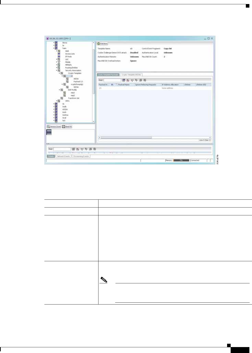
25-85
Cisco Prime Network 4.0 User Guide
OL-29343-01
Chapter 25 Monitoring Mobile Technologies LTE Networks
Figure 25-13 Crypto Template Details
Table 25-52 displays the Crypto template details.
Table 25-52 Crypto Template Details
Field Description
Template Name The unique name of the template.
Control Don’t Fragment The Don’t Fragment (DF) bit in the IPSec tunnel data packet, which is
encapsulated in the IPSec headers at both ends. The values for this field are:
• clear-bit—Clear DF Bit
• copy-bit—Copy DF bit from inner header
• set-bit—Set DF Bit
This field defaults to copy-bit.
Cookie Challenge-Detect
DOS Attack The cookie challenge parameters for the crypto template, which is used to
prevent malicious Denial of Service (DOS) attacks against the server.
Note This feature prevents DOS attacks by sending a challenge cookie. If
the response from the sender does not incorporate the expected
cookie data, the packets are dropped.

25-86
Cisco Prime Network 4.0 User Guide OL-29343-01
Chapter 25 Monitoring Mobile Technologies
LTE Networks
Notify Payload - Half
Open Session Start The initial count of the number of half-open sessions per IPSec manager.
Transmission of information will start only when the number of half-open
sessions currently open exceed the starting count.
Note A session is considered half open if a Packet Data Interworking
Function (PDIF) has responded to an IKEv2 INIT request with an
IKEv2 INIT response, but no further messages were received on the
particular IKE SA.
Notify Payload - Half
Open Session End The maximum count of half open sessions per IPSec manager. Transmission
of information will stop when the number of half-open sessions currently
open is less than this count.
Authentication Local The local gateway key used for authentication.
Authentication Remote The remote gateway key used for authentication.
Keepalive Interval The period of time (in seconds) that must elapse before the next keepalive
request is sent.
Keepalive Retries The period of time (in seconds) that must elapse before the keepalive request
is resent.
Keepalive Timeout The keepalive time (in terms of seconds) for dead peer detection.
Maxchild SA Count The maximum number of child SA per IKEv2 policy, which can be any value
between 1 and 4.
Maxchild SA Overload
Action The action to be taken when the specified soft limit for the maximum number
of SA is reached, which can be any one of the following:
Ignore—The IKEv2 stack ignores the specified soft limit for the SA and
allows new SA to be created.
Terminate—The IKEv2 stack does not allow new child SA to be created
when the specified soft limit is reached.
NAI CustomIDr The unique user specified identification number to be used in the crypto
template for Network Access Identifier (NAI).
Crypto Template Payloads
Payload Instance The payload instance configured for the crypto template.
Payload Name The unique name of the crypto template payload.
Ignore Rekeying
Requests Indicates whether IKESA rekeying requests must be ignored.
IP Address Allocation The IP Address Allocation scheme configured for the crypto template
payload.
Lifetime The lifetime (in seconds) for the IPSec Child Security Associations derived
from the crypto template.
Lifetime (KB) The lifetime (in kilo bytes) for the IPSec Child Security Associations derived
from the crypto template.
Maximum Child SA The maximum number of IPSec Child Security Associations (SA) that may
be derived from a single IKEv2 IKE SA.
Table 25-52 Crypto Template Details (continued)
Field Description

25-87
Cisco Prime Network 4.0 User Guide
OL-29343-01
Chapter 25 Monitoring Mobile Technologies LTE Networks
Viewing the EAP Profile Details
To view the EAP Profile details:
Rekey Indicates whether IPSec Child Security Association rekeying must be
enabled, after approximately 90% of the child SA lifetime has expired.
Rekey Keepalive Indicates whether rekeying must be allowed if data is not received on the
security association since the last rekey.
TSI Start Address The IKEv2 Initiator Traffic Selector payload start address configured for the
crypto template.
TSI End Address The IKEv2 Initiator Traffic Selector payload end address configured for the
crypto template.
TSR Start Address The IKEv2 Responder Traffic Selector payload start address.
TSR End Address The IKEv2 Responder Traffic Selector payload end address.
Crypto Template IKESAs
IKESA Instance The IKESA instance configured for the crypto template.
Allow Empty IKESA Indicates whether empty IKESA is allowed. By default, empty IKESA is not
allowed.
Certificate Sign The certificate sign to be used. This field defaults to pkcs1.5.
Ignore Notify Protocol
ID Indicates whether the IKEv2 Exchange Notify Payload Protocol-ID values
must be ignored for strict RFCA 4306 compliance.
Ignore Rekeying
Requests Indicates whether IKESA rekeying requests must be ignored.
Keepalive User Activity Indicates whether the user inactivity timer must be reset when keepalive
messages are received from the peer.
Max Retransmission The maximum number of retransmissions of an IKEv2 IKE exchange request
that is allowed if a response is not received.
Policy Congestion
Rejection Notify Status Indicates whether an error notification message must be sent in response to
an IKE_SA INIT exchange, when IKESA sessions cannot be established
anymore.
Policy Error Notification Indicates whether an error notification message must be sent for invalid
IKEv2 exchange message ID and syntax.
Rekey Indicates whether IKESA rekeying must occur before the configured
lifetime expires (which is approximately at 90% of the lifetime interval). By
default, rekeying is not allowed.
Retransmission Timeout The time period (in milliseconds) that must elapse before a retransmission of
an IKEv2 IKE exchange request is sent when a corresponding response is not
received.
Setup Timer The number of seconds before a IKEv2 security association, which is not
fully established, is terminated.
Table 25-52 Crypto Template Details (continued)
Field Description

25-88
Cisco Prime Network 4.0 User Guide OL-29343-01
Chapter 25 Monitoring Mobile Technologies
LTE Networks
Step 1 Right-click the required device in Prime Network Vision and choose Inventory.
Step 2 In the logical inventory window, choose Logical
Inventory > Context > Security Association > EAP Profile. The list of profiles are displayed in the
content pane.
Step 3 In the EAP Profile node, choose the profile. The profile details are displayed in the content pane.
Table 25-53 displays the EAP Profile details.
Viewing the Transform Set Details
To view the Transform Set details for IKEv2 IPSec/IKEv2:
Step 1 Right-click the required device in Prime Network Vision and choose Inventory.
Step 2 In the logical inventory window, choose Logical
Inventory > Context > Security Association > Transform Set > IKEv2 IPSec Transform Set or
IKEv2 Transform set. The list of profiles are displayed in the content pane.
Step 3 In the IKEv2 IPSec Transform Set or IKEv2 Transform set node, choose the transform set. The
relevant details are displayed in the content pane.
Table 25-54 displays the IKEv2 IPSec Transform set or IKEv2 Transform set details.
Table 25-53 EAP Profile Details
Field Description
Name The unique name of the EAP Profile.
Mode The operative mode of the EAP profile, which can be any one of the
following:
• Authenticator Pass Through—Indicates that the EAP Authentication
Requests must be passed to an external EAP Server.
• Authenticator Terminate—Indicates that the EAP must act as an EAP
Authentication Server.
Authentication Method The EAP Authentication method to be used for the profile, which can be any
one of the following:
• If the Mode is Authenticator Pass Through:
–
eap-aka
–
eap-gtc
–
eap-md5
–
eap-sim
–
eap-tls
• If the Mode is Authenticator Terminate:
–
eap-gtc
–
eap-md5

25-89
Cisco Prime Network 4.0 User Guide
OL-29343-01
Chapter 25 Monitoring Mobile Technologies LTE Networks
Table 25-54 IKEv2 IPSec Transform Set/IKEv2 Transform set Details
Field Description
Name The name of the transform set.
DH Group The Diffie-Hellman (DH) group for the transform set, which can be any one
of the following:
• 1—Configure Diffie-Hellman Group 1:768-bit MODP Group
• 14—Configure Diffie-Hellman Group 14:2048-bit MODP Group
• 2—Configure Diffie-Hellman Group 2:1024-bit MODP Group
• 5—Configure Diffie-Hellman Group 5:1536-bit MODP Group
This field defaults to 2—Configure Diffie-Hellman Group 2:1024-bit
MODP Group.
Note The DH group is used to determine the length of the base Prime
numbers used during the key exchange process in IKEv2. The
cryptographic strength of any key derived, depends in part, on the
strength of the DH group upon which the prime numbers are based.
Cipher The appropriate encryption algorithm and encryption key length for the
IKEv2 IKE security association, which can be any one of the following:
• 3des-cbc
• aes-cbc-128
• aes-cbc-256
• des-cbc
• Null
This field defaults to AESCBC-128.
HMAC The Hash Message Authentication Code (HMAC) for the IKEv2 IPSec
transform set,which can be any one of the following:
• aes-xcbc-96
• md5-96
• sha1-96
• sha2-256-128
• sha2-384-192
• sha2-512-256
This field defaults to sha1-96.
Note HMAC is a type of message authentication code calculated using a
cryptographic hash function in combination with a secret key to
verify both data integrity and message authenticity. A hash takes a
message of any size and transforms it into a message of fixed size
(the authenticator value), which is truncated and transmitted.

25-90
Cisco Prime Network 4.0 User Guide OL-29343-01
Chapter 25 Monitoring Mobile Technologies
LTE Networks
Viewing the ePDG Configuration Details
To view the ePDG configuration details:
Step 1 Right-click the required device in Prime Network Vision and choose Inventory.
Step 2 In the logical inventory window, choose Logical Inventory > Context > Mobile > EPDG. The list of
EPDG services configured in Prime Network are displayed in the content pane.
Step 3 From the EPDG node, choose an EPDG service. The EPDG service details are displayed in the content
pane.
Table 25-55 displays the EPDG service details.
Mode The encapsulation mode for the transform set, which can be any one of the
following:
• transport
• tunnel
PRF The Pseudo-random Function (PRF) for the transform set, which can be any
one of the following:
• aes-xcbc-128
• md5
• sha1
• sha2-256
• sha2-384
• sha2-512
This field defaults to SHA1. This field is applicable only for IKEv2
transform sets.
Note This function is used to generate keying material for all
cryptographic algorithms. It produces a string of bits that cannot be
distinguished from random bit strings without the secret key.
Life Time The time period for which the secret keys used for various aspects of a
configuration is valid (before it times out). This field is applicable only for
IKEv2 transform sets.
Table 25-54 IKEv2 IPSec Transform Set/IKEv2 Transform set Details
Field Description

25-91
Cisco Prime Network 4.0 User Guide
OL-29343-01
Chapter 25 Monitoring Mobile Technologies LTE Networks
Table 25-55 EPDG Service Details
Field Description
Service Name The unique name of the ePDG service.
Status The status of the ePDG service, which can be any one of the following:
• Initiated
• Running
• Down
• Started
• Nonstarted
IP Address The IPV4 address of the ePDG service.
UDP Port The User Datagram Protocol (UDP) port of the ePDG service.
Crypto Template The name of the IKEv2 crypto template to be used by the ePDG service. This
template is used to define the cryptographic policy for the ePDG service.
Max Sessions The maximum number of sessions allowed for the ePDG service.
PLMN ID The unique identification code of the Public Land Mobile Network (PLMN)
for the ePDG service. This id is made up of the Mobile Country Code (MCC)
and the Mobile Network Code (MNC).
MAG Service Context The name of the context where the Mobile Access Gateway (MAG) services
are configured. If a MAG service is not configured for the ePDG service,
then one of the MAG services defined in the context is selected.
MAG Service The name of the MAG service that handles the mobile IPv6 sessions.
Setup Timeout The maximum time (in seconds) allowed for the session setup.
DNS PGWClient
Context The name of the context where the Domain Name System (DNS) client is
configured for the Packet Data Network Gateway (PWG) selection.
DNS PGW Selection The criteria to select a PGW service from the DNS. This criteria is based on
the topology and/or weight from the DNS.
FQDN The Fully Qualified Domain Name (FQDN), which is used for longest suffix
match during dynamic allocation.
PGW Selection Agent
Info Error Action The action to be taken when the expected MIP6 agent information is not
received from Authentication, Authorization, and Accounting (AAA) or
Hosting Solution Software (HSS).
User Name MAC
Address Stripping Indicates whether the MAC address in the username obtained from the user
equipment must be stripped.
User Name MAC
Address Validation Indicates whether the MAC address in the username obtained from the user
equipment must be validated.
User Name MAC
Address Validation
Failure Action
Indicates the action that must be taken on failure of the validation of the
MAC address in the user name obtained from the user equipment.
New Call Policy Indicates the busy-out policy that must be followed to reject the incoming
calls from individual users.

25-92
Cisco Prime Network 4.0 User Guide OL-29343-01
Chapter 25 Monitoring Mobile Technologies
LTE Networks
Configuration Commands for ePDG
The ePDG commands allow you to configure ePDG services in your network. Please note that these
commands are available only for Cisco ASR 5000 Mobile devices.
These commands can be launched from the logical inventory by choosing the
Context > Commands > Configuration or Context > Commands > Show.
Before executing any commands, you can preview them and view the results. If desired, you can also
schedule the commands.
The table below lists the ePDG commands. Additional commands may be available for your devices.
New commands are often provided in Prime Network Device Packages, which can be downloaded from
the Prime Network software download site. For more information on how to download and install DPs
and enable new commands, see the information on “Adding Additional Device (VNE) support” in the
Cisco Prime Network 4.0 Administrator Guide.
Note You might be prompted to enter your device access credentials while executing a command. Once you
have entered them, these credentials will be used for every subsequent execution of a command in the
same GUI client session. If you want to change the credentials, click Edit Credentials. The Edit
Credentials button will not be available for SNMP commands or if the command is scheduled for a later
time.
Table 25-56 lists the ePDG configuration commands.
Monitoring Packet Data Serving Node (PDSN)
Packet Data Serving Node, or PDSN, is a component of the Code Division Multiple Access (CDMA)
2000 mobile network. It acts as a connection point between the Radio Access Network (RAN) and IP
Network. PDSN also manages PPP sessions between the mobile provider’s core IP network and the
mobile node.
In other words, it provides access to the Internet, intranets, and applications servers for mobile stations
that utilize a CDMA2000 RAN. Acting as an access gateway, PDSN provides simple IP and mobile IP
access, foreign agent support, and packet transport for virtual private networking. It acts as a client for
Authentication, Authorization, and Accounting (AAA) servers and provides mobile stations with a
gateway to the IP network.
Table 25-56 ePDG Configuration Commands
Command Navigation Description
Create ePDG
Service Right-click context > Commands >
Configuration > Use this command to create a new ePDG
service.
Modify ePDG
Service Expand EPDG Node > right-click EPDG
service > Commands > Configuration Use this command to modify the
configuration details for an ePDG service.
Delete ePDG
Service Expand EPDG Node > right-click EPDG
service > Commands > Configuration Use this command to delete an ePDG
service.
Show ePDG
Service Expand EPDG Node > right-click EPDG
service > Commands > Show Use this command to view and confirm the
configuration details of an ePDG Service.
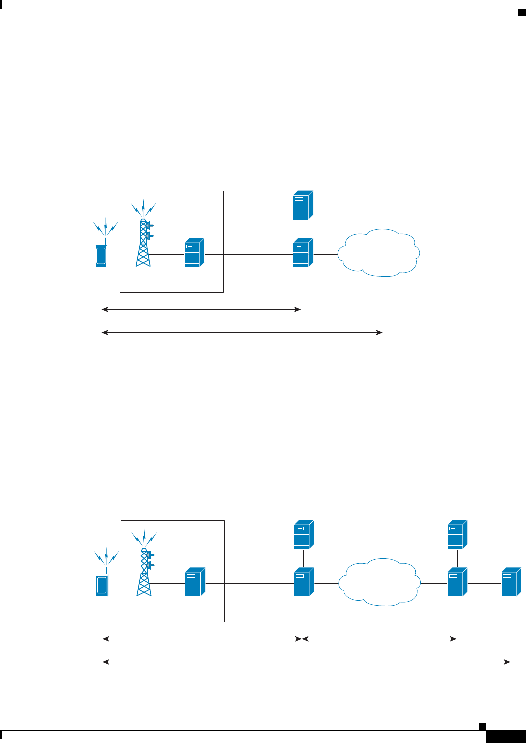
25-93
Cisco Prime Network 4.0 User Guide
OL-29343-01
Chapter 25 Monitoring Mobile Technologies LTE Networks
PDSN Configurations
The following paragraphs list the different configurations for PDSN:
• Simple IP—In this protocol, the mobile user is assigned an IP address dynamically. The user can use
this IP address within a defined geographical area, which is lost when the user moves out of the area.
If the user moves out of the designated area, they must register with the service provider again to
obtain a new IP address. Figure 25-14 depicts the working of this protocol.
Figure 25-14 Simple IP configuration for PDSN
• Mobile IP—In this protocol, the mobile user is assigned a static or dynamic IP address, which is
basically the “home address” assigned by the user’s Home Agent (HA). Even if the user moves out
of the home network, the IP address does not change or is not lost. This enables the user to use
applications that require seamless mobility such as transferring files. How does this work? The
Mobile IP protocol provides a network-layer solution that allows mobile nodes to receive IP packets
from their home network even when they are connected to a visitor network. The PDSN in the
visitor’s network performs as a Foreign Agent (FA), which assigns a Care-of-Address (CoA) to the
mobile node and establishes a virtual session with the mobile node’s HA. IP packets are
encapsulated into IP tunnels and transported between the FA, HA and mobile node. Figure 25-15
depicts the working of this protocol.
Figure 25-15 Mobile IP Configuration for PDSN
Radio
Tower
Radio Access Network (RAN)
BSC/PCFMN
320495
PDSN
PPP
Foreign AAA
R-P Interface Internet
or PDN
IP
Radio
Tower
Radio Access Network (RAN)
BSC/PCFMN
320492
PDSN/FA
PPP
Foreign AAA
R-P Interface
HA CN
Home AAA
Internet
or PDN
IP in IP or GRE Tunnel
IP
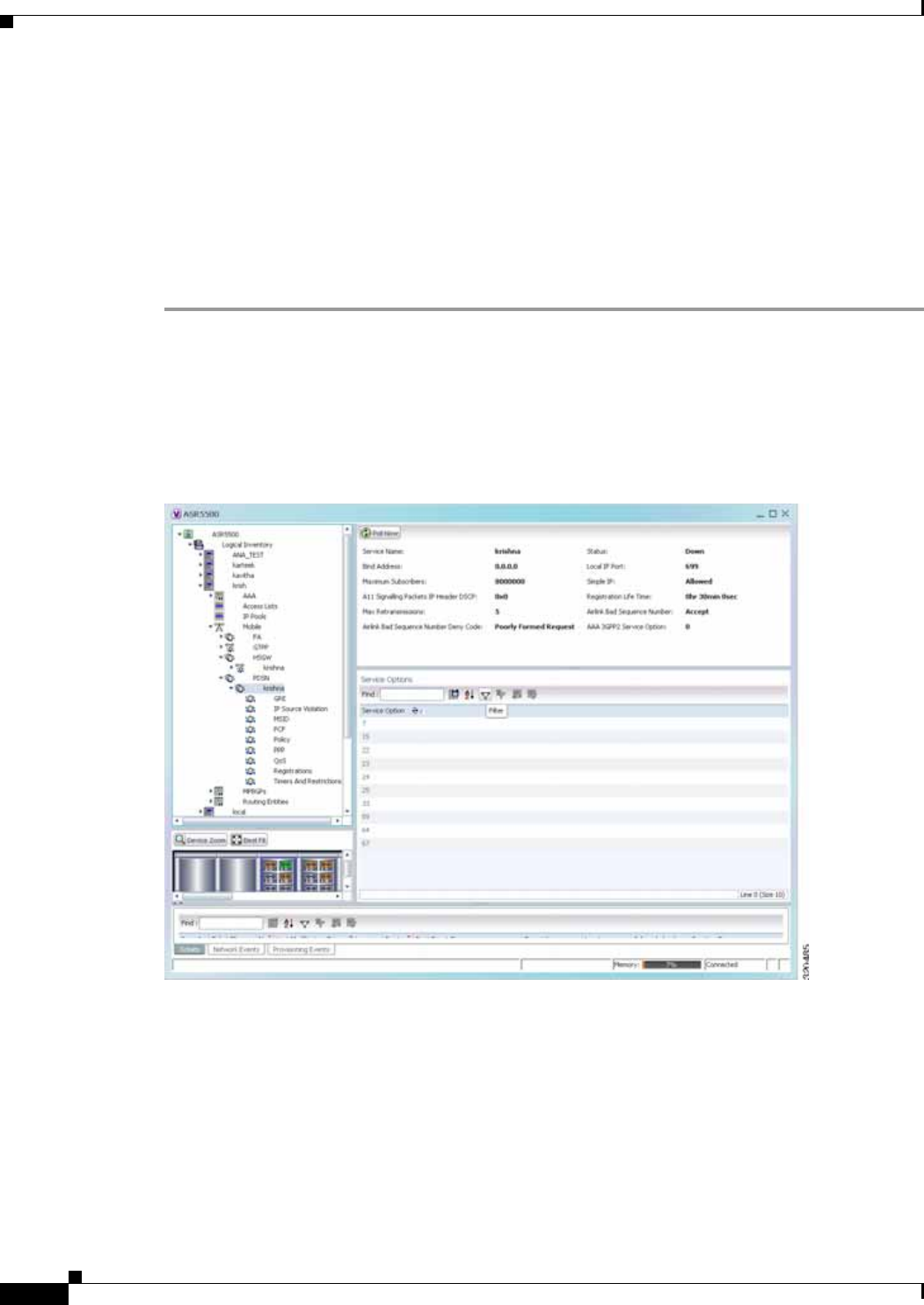
25-94
Cisco Prime Network 4.0 User Guide OL-29343-01
Chapter 25 Monitoring Mobile Technologies
LTE Networks
• Proxy Mobile IP—This protocol provides a mobility solution for subscribers whose mobile nodes
do not support the Mobile IP protocol. On behalf of the mobile node, PDSN proxies the Mobile IP
tunnel with the HA. In turn, the service provider or the home agent assigns an IP address to the
subscriber. This IP address does not change or is not lost even if the user moves out of the home
network.
Viewing the PDSN Configuration Details
To view the PDSN configuration details:
Step 1 Right-click the required device in Prime Network Vision and choose Inventory.
Step 2 In the logical inventory window, choose Logical Inventory > Context > Mobile > PDSN. The list of
PDSN services configured in Prime Network are displayed in the content pane.
Step 3 From the PDSN node, choose a PDSN service. The PDSN service details are displayed in the content
pane as shown in Figure 25-16.
Figure 25-16 PDSN Service Details
Table 25-57 displays the PDSN service details.

25-95
Cisco Prime Network 4.0 User Guide
OL-29343-01
Chapter 25 Monitoring Mobile Technologies LTE Networks
Table 25-57 PDSN Service Details
Field Description
Service Name The unique name of the PDSN service.
Status The status of the PDSN service, which can be any one of the following:
• Initiated
• Running
• Down
• Started
• Nonstarted
• Unknown
Bind Address The IP address to which the service is bound. This can be a IPv4 or IPv6
address.
Note Multiple IP addresses belonging to the same IP interface can be
bound to different PDSN services, but one address can be bound to
only one service.
Local IP Port The User Datagram Protocol (UDP) port for the R-P interface of the IP
socket. This IP port can be any value between 1 and 65535 and defaults to
699.
Mobile IP The IP address of the Foreign agent that is configured for the PDSN service.
Simple IP Indicates whether the Simple IP configuration is available for the PDSN
service, which can be any one of the following:
• Allowed
• Not Allowed (default value)
Max Subscribers The maximum number of subscribers that the PDSN service can support.
Registration Life Time The registration lifetime configured for all the subscribers to the service.
Max Retransmissions Maximum retries for transmitting RP control packets. This count can be any
value between 1 and 1000000 and defaults to 5.
A11 Signalling Packets
IP Header DSCP The Differential Services Code Point (DSCP) value in the IP header.
NAI Construction
Domain The Network Access Identifier for the PDSN service. This field is made up
of the Mobile Station Identifier (MSID) of the subscriber, a separator
character and a domain name.
Note The domain name used here can be either the name supplied as part
of the subscriber’s name or the domain alias.

25-96
Cisco Prime Network 4.0 User Guide OL-29343-01
Chapter 25 Monitoring Mobile Technologies
LTE Networks
You can also view the following configuration details for a PDSN service:
• GRE
• IP Source Violation
• MSID
• PCF
• Policy
• PPP
• QoS
• Registrations
• Timers and Restrictions
Viewing the GRE Configuration Details
To view the Generic Routing Encapsulation (GRE) configuration details for a PDSN service:
Step 1 Right-click the required device in Prime Network Vision and choose Inventory.
Step 2 In the logical inventory window, choose Logical Inventory > Context > Mobile > PDSN > PDSN
service > GRE. The GRE details are displayed in the content pane.
Table 25-58 displays the GRE configuration details.
Airlink Bad Sequence
Number The action to be taken when the PDSN receives an airlink record with a bad
sequence number, which can be any one of the following:
• Accept (default value)
• Reject
Note At the time of the R-PA10 connection setup, an airlink record is
assigned a unique sequence number.
Airlink Bad Sequence
Number Deny Code The reason for rejecting the airlink record with a bad sequence number,
which can be any one of the following:
• Poorly Formed Request
• Unsupported Vendor ID
AAA 3GPP2 Service
Option The service options for which AAA 3GPP2 authentication is applicable.
Service Option Entries
Service Option Number The service option numbers applicable for the PDSN service.
Note Each service option relates to a standard data service. Hence, these
numbers determine the data services that are supported by the PDSN
service.
Table 25-57 PDSN Service Details (continued)
Field Description

25-97
Cisco Prime Network 4.0 User Guide
OL-29343-01
Chapter 25 Monitoring Mobile Technologies LTE Networks
Table 25-58 GRE Configuration Details
Field Description
Checksum Indicates whether the Checksum field is applicable for outgoing GRE
packets.By default, this option is disabled.
Checksum Verify Indicates whether the verification of the Checksum field is enabled for
incoming GRE packets.
Reorder Time Out The maximum time (in milliseconds) for processing the GRE packets that
are coming out of order. This time can be any value between 0 and 5000, and
defaults to 100 milliseconds.
Sequence Mode The mode in which incoming out-of-sequence GRE packets are handled,
which can be any one of the following:
• Reorder
• None
This field defaults to None.
Sequence Numbers Indicates whether GRE sequence numbers are inserted in data that is about
to be transmitted over the A10 interface. By default, this option is disabled.
Flow Control Indicates whether flow control is supported by the selected PDSN service. If
this option is enabled, PDSN sends flow control enabled Normal Vendor
Specific Extensions (NSVE) in A11 RRPs. By default, this option is
disabled.
Flow Control Time Out The amount of time (in milliseconds) to wait for an Transmitter On (XON)
indicator from the RAN. This time can be any value between 1 and 1000000,
and defaults to 1000 milliseconds.
Flow Control Action The action that must be taken when the timeout limit is reached, which can
be any one of the following:
• disconnect-session
• resume-session.
Protocol Type The tunnel type for the GRE routing. This field defaults to Any.
Is 3GPP Ext Header
QoS Marking Indicates whether the 3GPP Extension Header QoS Marking is enabled for
the selected PDSN feature.
Note If this feature is enabled and the PCF negotiation feature is enabled
in A11 RRQ, then the PDSN will include QoS optional data attribute
in the GRE 3GPP2 Extension Header.
IP Header DSCP Value The Differential Service Code Point (DSCP) value in the IP header that
marks the GRE IP Header encapsulation. This can be any value between
0x0F and 0X3F, and defaults to 0X0F.
IP Header DSCP Value
Packet Type Indicates whether the IP Header DSCP Value packet type is specified for the
packets. By default, this option is disabled.
GRE Segmentation Indicates whether segmentation of GRE packets is enabled. By default, this
option is disabled.

25-98
Cisco Prime Network 4.0 User Guide OL-29343-01
Chapter 25 Monitoring Mobile Technologies
LTE Networks
Viewing the IP Source Violation Details
A Source violation occurs when a mobile device sources packets to the PDSN with a IP address that is
different from the one specified during setup. Using this feature, the packets that need not be sent over
the network are dropped when it tries to pass through PDSN.
To view the IP Source Violation configuration details for a PDSN service:
Step 1 Right-click the required device in Prime Network Vision and choose Inventory.
Step 2 In the logical inventory window, choose Logical Inventory > Context > Mobile > PDSN > PDSN
service > IP Source Violation. The details are displayed in the content pane.
Table 25-59 displays the IP Source Violation configuration details.
Viewing the MSID Configuration Details
To view the Mobile Station ID (MSID) configuration details for a PDSN service:
Step 1 Right-click the required device in Prime Network Vision and choose Inventory.
Step 2 In the logical inventory window, choose Logical Inventory > Context > Mobile > PDSN > PDSN
service > MSID. The details are displayed in the content pane.
Table 25-60 displays the MSID configuration details.
Table 25-59 IP Source Violation Configuration Details
Field Description
Clear on Valid Packet Indicates whether the service to reset the negotiation and drop limit counters
upon receipt of properly addressed packet is enabled. By default, this feature
is disabled.
Drop Limit The maximum number of IP source violations within the detection period,
before the call is dropped. This number can be any value between 0 and
1000000, and defaults to 10.
Period The detection period (in seconds) for the IP source violation. This field can
be any value between 1 and 1000000, and defaults to 120.
Renegotiation Limit The maximum number of IP source violations within the detection period
before renegotiating PPP for the call. This field can be any value between 1
and 1000000, and defaults to 5.
Table 25-60 MSID Configuration Details
Field Description
MSID Length Max The maximum length of the MSID configured for the PDSN service. This
length can be any value between 10 and 15, and defaults to 15.
MSID Length Min The minimum length of the MSID configured for the PDSN service. This
length can be any value between 10 and 15, and defaults to 10.

25-99
Cisco Prime Network 4.0 User Guide
OL-29343-01
Chapter 25 Monitoring Mobile Technologies LTE Networks
Viewing the PCF Configuration Details
To view the Packet Control Function (PCF) configuration details for a PDSN service:
Step 1 Right-click the required device in Prime Network Vision and choose Inventory.
Step 2 In the logical inventory window, choose Logical Inventory > Context > Mobile > PDSN > PDSN
service > PCF. The details are displayed in the content pane.
Table 25-61 displays the PCF configuration details.
MSID Authentication Indicates whether the MSID authentication feature is enabled.
MSID Length Check Indicates whether MSID length is enabled for the PDSN service. By default,
this option is disabled.
Note This configuration is required to reject the A11-RRQs with illegal
International Mobile Station Identification (IMSI).
Table 25-60 MSID Configuration Details
Field Description
Table 25-61 PCF Configuration Details
Field Description
PCF Monitor Num
Retries The maximum number of retries before deciding that the PCF service is
down.
PCF Session ID Change
Restart PPP Indicates whether the PPP must be restarted if there is a change in the session
ID of an existing session.
New Call Conflict
Terminate Old Session Indicates whether the session with a PCF must be terminated when a new call
request for an existing session is received from another PCF.
PDSN Security Entries
SPI Number The unique Security Parameters Index number that indicates a security
context between the services.
Remote Address The IP address of the source service.
Netmask The subnet mask of the source service.
Zone ID The ID of the zone to which the IP address belongs to.
Hash Algorithm The hash algorithm used to encrypt the data.
Time Stamp Tolerance The acceptable difference (in seconds) in the timestamps.
Note If the actual difference exceeds the difference specified here, then
the session is rejected. If this difference is 0, the timestamp tolerance
checking is disabled at the receiving end.
Replay Protection The replay protection schemes that is implemented by the service.
Description The description of the security profile.

25-100
Cisco Prime Network 4.0 User Guide OL-29343-01
Chapter 25 Monitoring Mobile Technologies
LTE Networks
Viewing the Policy Configuration Details
To view the Policy configuration details for a PDSN service:
Step 1 Right-click the required device in Prime Network Vision and choose Inventory.
Step 2 In the logical inventory window, choose Logical Inventory > Context > Mobile > PDSN > PDSN
service > Policy. The details are displayed in the content pane.
Table 25-62 displays the Policy configuration details.
Viewing the PPP Configuration Det4
To view the Point-to-Point Protocol details for a PDSN service:
Step 1 Right-click the required device in Prime Network Vision and choose Inventory.
Step 2 In the logical inventory window, choose Logical Inventory > Context > Mobile > PDSN > PDSN
service > PPP. The details are displayed in the content pane.
Table 25-63 displays the PPP configuration details.
Table 25-62 Policy Configuration Details
Field Description
Unknown CVSE Policy Indicates whether the unknown Critical Vendor Specific Extension (CVSE)
policy is enforced.
RRQ MEI From Current
PCF Indicates whether PPP must be restarted after getting MEI in RRQ.
New Call Policy The call policy for one or all the services, which can be any one of the
following:
• Accept
• Reject
• Redirect
• Reject on MSID
• Redirect on MSID
• None
This field defaults to None.
Overload Policy The action to be taken by the PDSN service in case of an overload condition.
Overload Policy Reject
Code The reject code for the overload policy.
Service Option Policy The policy followed by PDSN for configuring services.
Reject MSID The Mobile Station Identifier (MSID) for which new calls are rejected.
Note If the New Call Policy field is set to Reject MSID, then this field
will display the relevant MSID.

25-101
Cisco Prime Network 4.0 User Guide
OL-29343-01
Chapter 25 Monitoring Mobile Technologies LTE Networks
Viewing the QoS Configuration Details
To view the Quality of Service configuration details for a PDSN service:
Step 1 Right-click the required device in Prime Network Vision and choose Inventory.
Step 2 In the logical inventory window, choose Logical Inventory > Context > Mobile > PDSN > PDSN
service > QoS. The details are displayed in the content pane.
Table 25-64 displays the QoS configuration details.
Table 25-63 PPP Configuration Details
Field Description
Context Name The destination context where the Layer 2 Tunneling protocol Access
Concentrator (LAC) service is configured.
Note This context is the same as the PPP tunneling context.
Tunnel Type The type of the PPP tunnel established between the PDSN and the PFC,
which can be any one of the following values:
• L2TP
• None
This field defaults to None.
Fragment State Indicates whether the PPP fragmentation is enabled. By default, this is
option is disabled.
Alt PPP Indicates whether the Alternate Point-to-Point (PPP) protocol sessions are
enabled for the PDSN service. By default, this option is disabled.
Allow No
Authentication Indicates whether subscribers can gain network access even if they have not
been authenticated.
Authentication The authentication mode and priority when multiple modes are selected,
which can be any one of the following:
• chap—Uses the Challenge Handshake Authentication Protocol (CHAP)
for authentication. Must be followed by a priority value, which can be
any value between 0 and 1000 with a lower number indicating higher
preference. This protocol is enabled by default and commands the
highest priority.
• mschap—Uses the Microsoft Challenge Handshake Authentication
Protocol (MS-CHAP) for authentication. Must be followed by a priority
value, which can be any value between 0 and 1000 with a lower number
indicating higher preference. This protocol is disabled by default.
• pap—Uses Password Authentication Protocol (PAP) for authentication.
Must be followed by a priority value, which can be any value between 0
and 1000 with a lower number indicating higher preference. This
protocol seconds CHAP in terms of priority. This protocol is enabled by
default.

25-102
Cisco Prime Network 4.0 User Guide OL-29343-01
Chapter 25 Monitoring Mobile Technologies
LTE Networks
Viewing the Registration Details
To view the Registration details for a PDSN service:
Step 1 Right-click the required device in Prime Network Vision and choose Inventory.
Step 2 In the logical inventory window, choose Logical Inventory > Context > Mobile > PDSN > PDSN
service > Registrations. The details are displayed in the content pane.
Table 25-65 displays the Registration details.
Table 25-64 QoS Configuration Details
Field Description
Policy Mismatch Indicates whether the PDSN must raise a Traffic FLow Template (TFT)
violation if there is a policy mismatch of QoS.
Qos Wait Indicates whether parameters related to QoS are enabled.
Note While configuring parameters for QoS, the minimum and maximum
waiting time for transmission are also specified. Also, the action to
be performed when the minimum time elapses is also specified.
Associate The unique identification number of the associated QoS Profile that is
configured for the selected context.
QoS Profile tab
ID The unique code of the QoS profile.
Description The description of the QoS profile.
Uplink Bandwidth The uplink bandwidth (in kbps) of your profile.
Downlink Bandwidth The downlink bandwidth (in kbps) of your profile.
Latency The latency (in milliseconds) of the profile.
Drop Rate The maximum drop rate percent of the packet.
QoS Class The type of QoS class associated with the profile.
Table 25-65 Registration Details
Field Description
Accept Session
Disconnect In Progress Indicates whether A11 registration request messages must be accepted from
the PCF when a session disconnection is in progress.
Ask Deny Terminate
Session on Error Indicates whether A11 sessions must be terminated when a registration
acknowledgement is received from PCF with an error status.
Max Deny Reply Limit Maximum number of retries for an erroneous registration request message
from PCF, before PDSN terminates the session.
Deny Mismatched COA
Address Indicates whether RP Requests must be denied, when the Care of Address
field does not match the source address of the requests.

25-103
Cisco Prime Network 4.0 User Guide
OL-29343-01
Chapter 25 Monitoring Mobile Technologies LTE Networks
Viewing the Timers and Restrictions Details
To view the Timers and Restrictions details for a PDSN service:
Step 1 Right-click the required device in Prime Network Vision and choose Inventory.
Step 2 In the logical inventory window, choose Logical Inventory > Context > Mobile > PDSN > PDSN
service > Timers and Restrictions. The details are displayed in the content pane.
Deny New Call
Connection Setup
Record Absent
Indicates whether new calls that do not have airlink connection setup record
in the RRQ must be denied.
Deny New Call
Connection Setup
Record Absent Deny
Code
The reason for denying new calls that do not have airlink connection setup
record in RRQ.
Deny New Call
Connection Reverse
Tunnel Unavailable
Indicates whether new calls whose GRE key is the same as that of another
user must be denied.
Deny Session Already
Active Indicates whether renew requests that have Airlink Start record for already
active R-P sessions must be denied.
Deny Session Already
Closed Indicates whether renew and de registration requests for closed R-P sessions
must be denied.
Deny Session Already
Dormant Indicates whether renew requests that have Airlink Start record for already
dormant R-P sessions must be renewed.
Deny Terminate Session
On Error Indicates whether termination of session on receipt of erroneous registration
request message must be denied.
Deny Use Zero GRE
Key Indicates whether the GRE key must be initialized to 0 when denying a new
R-P session.
Discard Bad Extension Indicates whether A11 registration request messages containing bad
extensions must be discarded.
Discard GRE Key
Change Indicates whether A11 registration request messages for an existing A11
session that contain a different GRE key must be discarded.
Update Wait Timeout The time taken (in seconds) by A11 RRQ for QoS changes.
Table 25-65 Registration Details (continued)
Field Description

25-104
Cisco Prime Network 4.0 User Guide OL-29343-01
Chapter 25 Monitoring Mobile Technologies
LTE Networks
Table 25-66 Timers and Restrictions Details
Field Description
Inter PDSN Handoff Indicates whether the Inter-PDSN handoff feature off is enabled.
Inter-PDSN handoff relates to the handoff between two PCFs with
connectivity to different PDSNs.
Note Inter-PDSN handoff can be of two types: Fast Handoff and Dormant
Handoff. Fast Handoff uses a GRE tunnel between two PDSNs to
transport user data for a single service instance. Dormant Handoff
occurs when a mobile station with a dormant packet session
determines that it has crossed a packet zone boundary.
Inter PDSN Handover
Use CANIDPANID Indicates whether usage of Current Access Network ID (CANID) or
Previous Access Network ID (PAN) is supported during an Inter-PDSN
handover.
Data Available
Indicator Indicates whether data transfer is available.
PMA Capability
Indicator The Proxy Mobile Agent capability (PMA) indicator, which determines
whether PMIP is supported by Prime Network.
Note PDSN sends the capability indicator through RADIUS to the AAA
server as an access-request packet to indicate to the AAA server that
PDSN supports PMIP. If the capability indicator attribute is missing,
then PMIP is not supported by PDSN.
Direct LTE Indicator Indicates whether PDSN can send Direct LTE indicator in the Access
Request.
Data Over Signalling Indicates whether data transfer over a10 signalling channel instead of bearer
or subscriber channels from PCF or PDSN is allowed. By default, this
feature is not allowed.
Dormant Transition Indicates whether dormant transition of the RP link during the initial setup
of the subscriber session is allowed. If this option is disabled, then the
subscriber session will be disconnected if the RP link becomes dormant
during the initial setup.
ROHC IP Header
Compression Indicates whether the Robust Header Compression (ROHC) is enabled for
headers in the IP packets that are being sent by or sent to the PDSN. By
default, this option is disabled.
Always On Indication Indicates whether the Always On feature is enabled for a subscriber.
Note When the idle-time out limit runs out for a subscriber, the IP/PPP
session remains connected as long as the subscriber is reachable. By
default, this feature is disabled.
Setup TimeOut The maximum time (in seconds) allowed for a session to be setup between
PCF and PDSN. This time can be any value between 1 and 1000000, and
defaults to 60 seconds.

25-105
Cisco Prime Network 4.0 User Guide
OL-29343-01
Chapter 25 Monitoring Mobile Technologies LTE Networks
Configuration Commands for PDSN
The PDSN commands allow you to configure PDSNs in your network. Please note that these commands
are available only for Cisco ASR 5000 Mobile devices.
These commands can be launched from the logical inventory by choosing the
Context > Commands > Configuration or Context > Commands > Show.
Before executing any commands, you can preview them and view the results. If desired, you can also
schedule the commands.
The table below lists the PDSN commands. Additional commands may be available for your devices.
New commands are often provided in Prime Network Device Packages, which can be downloaded from
the Prime Network software download site. For more information on how to download and install DPs
and enable new commands, see the information on “Adding Additional Device (VNE) support” in the
Cisco Prime Network 4.0 Administrator Guide.
Note You might be prompted to enter your device access credentials while executing a command. Once you
have entered them, these credentials will be used for every subsequent execution of a command in the
same GUI client session. If you want to change the credentials, click Edit Credentials. The Edit
Credentials button will not be available for SNMP commands or if the command is scheduled for a later
time.
Table 25-67 lists the PDSN configuration commands.
Retransmission
TimeOut The timeout period (in seconds) for retransmission of RP control packets.
This time can be any value between 1 and 1000000 and defaults to 3 seconds.
Pdsn Type0 Tft Indicates whether Traffic Flow Template (TFT) of the PDSN is changed
from type 0 TFT to type 1 TFT.
Tft Validation TimeOut The TFT validation timeout (in seconds) for QoS changes. This time can be
any value between 1 and 100000, and defaults to 0.
Access Flow Traffic
Violations The number of violations that are permitted in the access flow traffic.
Access Flow Traffic
Violations Interval The time interval between two subsequent access flow traffic violations.
Table 25-66 Timers and Restrictions Details (continued)
Field Description
Table 25-67 PDSN Configuration Commands
Command Navigation Description
Create PDSN Right-click on a context > Commands
> Configuration Use this command to create a new PDSN
service for the selected context.
Modify
PDSN
Delete PDSN
Expand PDSN node > right-click
PDSN service > Commands >
Configuration
Use these commands to modify/delete an
existing PDSN service configured for the
selected context.

25-106
Cisco Prime Network 4.0 User Guide OL-29343-01
Chapter 25 Monitoring Mobile Technologies
LTE Networks
Viewing the Local Mobility Anchor Configuration (LMA)
Proxy Mobile IPv6 (or PMIPv6, or PMIP) is a network-based mobility management protocol for
building a common access technology independent of mobile core networks, accommodating various
access technologies such as WiMAX, 3GPP, 3GPP2 and WLAN based access architectures.
The PMIPv6 provides network-based IP Mobility management to a mobile node, without requiring the
participation of the MN in any IP mobility-related signaling. The mobility entities in the network track
the movements of the MN, initiate the mobility signaling, and set up the required routing state.
Show PDSN Expand PDSN node > right-click
PDSN service > Commands > Show Use this command to view and confirm the
PDSN service configuration details.
Modify GRE Expand PDSN node > PDSN service >
right-click GRE > Commands >
Configuration
Use this command to modify the Generic
Routing Encapsulation (GRE) configuration
settings for a specified PDSN service.
Modify IP
Source
Violation
Expand PDSN node > PDSN service >
right-click IP Source Violation >
Commands > Configuration
Use this command to modify the IP Source
Violation configuration details for the
specified PDSN service.
Modify
MSID Expand PDSN node > PDSN service >
right-click MSID > Commands >
Configuration
Use this command to modify the mobile
station ID (MSID) configuration details for
the specified PDSN service.
Modify PCF
Parameters Expand PDSN node > PDSN service >
right-click PCF > Commands >
Configuration
Use this command to modify the Packet
Control Function (PCF) configuration details
for the specified PDSN service.
Create PCF
Security
Entry
Expand the PDSN node > right-click
PDSN service > Commands >
Configuration
Use this command to create a new PCF
security entry.
Modify PCF
Security
Entry
Delete PCF
Security
Entry
Expand PDSN node > PDSN service >
PCF > Under Security Profiles tab n
the content pane, right-click SPI
Number > Commands >
Configuration
Use these commands to modify/delete the
PCF security entry details.
Modify
Policy Expand PDSN node > PDSN service >
right-click Policy > Commands >
Configuration
Use this command to modify the policy
configuration details for the PDSN service.
Modify PPP Expand PDSN node > PDSN service >
right-click PPP> Commands >
Configuration
Use this command to modify the
Point-to-Point Protocol configuration details
for the selected PDSN service.
Modify
Registrations Expand PDSN node > PDSN service >
right-click Registrations >
Commands > Configuration
Use this command to modify the registration
details for the selected PDSN service.
Modify
Timers and
Registrations
Expand PDSN node > PDSN service >
right-click Timers and Registrations
> Commands > Configuration
Use this command to modify the timers and
registration details for the selected PDSN
service.
Table 25-67 PDSN Configuration Commands (continued)
Command Navigation Description
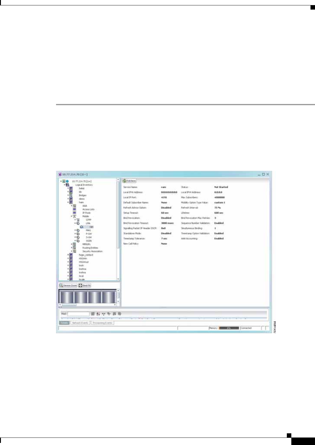
25-107
Cisco Prime Network 4.0 User Guide
OL-29343-01
Chapter 25 Monitoring Mobile Technologies LTE Networks
The major functional entities of PMIPv6 are Mobile Access Gateways (MAGs), Local Mobility Anchors
(LMAs), and Mobile Nodes (MNs).
The Local Mobility Anchor (LMA) is the home agent for a mobile node in a Proxy Mobile IPv6
(PMIPv6) domain. It is the topological anchor point for mobile node home network prefixes and
manages the binding state of an mobile node. An LMA has the functional capabilities of a home agent
as defined in the Mobile IPv6 base specification (RFC 3775) along with the capabilities required for
supporting the PMIPv6 protocol.
To view the LMA configuration details:
Step 1 Right-click the required device in Prime Network Vision and choose Inventory.
Step 2 In the logical inventory window, choose Logical Inventory > Context > Mobile > LMA. The list of
LMA services configured in Prime Network is displayed in the content pane.
Step 3 From the LMA node, choose an LMA service. The LMA service details are displayed in the content pane
as shown in Figure 25-17.
Figure 25-17 LMA Service Details
Table 25-68 displays the LMA service details.

25-108
Cisco Prime Network 4.0 User Guide OL-29343-01
Chapter 25 Monitoring Mobile Technologies
LTE Networks
Table 25-68 LMA Service Details
Field Description
Service Name The unique service name of the LMA.
Status The status of the LMA service, which can be any one of the following:
• Down
• Running
• Initiated
• Unknown.
This field defaults to Down.
Local IPv6 Address The IP address of the interface serving as S2a (that is connected to HSGW)
or S5/S8 (that is connected to S-GW) interface.
Local IPv4 Address The IP address of the interface connected to HA/P-GW.
Local IP Port The User Datagram Protocol (UDP) port for the LMA service.
Max Subscribers The maximum number of subscribers that the LMA service can support. This
number can be any value between 0 and 3000000.
Default Subscriber
Name The name of the subscriber template to be used for subscribers who are using
this domain alias.
Mobility Option Type
Value The mobility option type used in mobility messages, which can be any one
of the following:
• Custom 1
• Custom 2
• Standard
Refresh Advice Option Indicates whether refresh advice option must be included in the Binding
Acknowledgement sent by the LMA service. By default, this option is
disabled.
Refresh Interval The percent of granted lifetime to be used in the Refresh Interval Mobility
option pertaining to the Binding Acknowledgement sent by the LMA
service. This percentage can be any value between 1 and 99 and defaults to
75.
Setup Timeout The maximum time (in seconds) allowed for the session to setup. This field
defaults to 60.
Lifetime The registration lifetime (in seconds) of the mobile IPv6 session. This
number can be any value between 1 and 262140.
Bind Revocation Indicates whether the binding revocation support is available for the LMA
service. By default, this option is disabled.
Bind Revocation Max
Retries The maximum number of retries for the binding revocation, which can be
any value between 1 and 10. This field defaults to 3.
Bind Revocation
Timeout The time interval (in milliseconds) of the retransmission of the binding
revocation, which can be any value between 500 and 10000. This field
defaults to 3000.
Sequence Number
Validation Indicates whether the sequence number of the MIPv6 control packet received
by the LMA service must be validated. This option is enabled by default.

25-109
Cisco Prime Network 4.0 User Guide
OL-29343-01
Chapter 25 Monitoring Mobile Technologies Scheduling 3GPP Inventory Retrieval Requests
Scheduling 3GPP Inventory Retrieval Requests
The 3GPP Inventory Management Web Services for Prime Network Integration Layer (PN-IL) retrieves
the physical and logical inventory data from the Prime Network managed devices. For details on
supported network elements, see Cisco Prime Network 4.0 Supported Cisco VNEs. For more details on
the 3GPP inventory management and the web services, refer to the Cisco Prime OSS Integration Guide,
2.0.
Prime Network allows you to schedule a web service operations for Prime Network Integration Layer to
run immediately or at a later point in time. Using Prime Network - Web Service Scheduler option, you
can do the following:
• Select the inventory request type based on which the inventory data will be retrieved from either all
the supported devices or from the specified devices under Prime Network.
• Schedule the 3GPP inventory management web service operations to initiate the inventory request
and executes it according to the specified schedule.
To schedule web services:
Step 1 In Prime Network Vision, Prime Network Events, or Prime Network Administration, choose
Tools > Web Service Scheduler.
Step 2 In the Web Service Scheduler window, select General tab and select the inventory request type.
Table 25-69 describes the details of the Web Service Scheduler - General tab.
Signalling Packet IP
Header DSCP The Differentiated Services Code Point (DSCP) marking that is applicable
to the IP header that is carrying outgoing signalling packets.
Simultaneous Binding The maximum number of Care of addresses that can be bound for the same
user as identified by their Network Access Identifier (NAI) and home
address. This can be any value ranging from 1 to 3. This field defaults to 1.
Standalone Mode Indicates whether the LMA service can be started in the standalone mode.
This option is disabled by default.
Timestamp Option
Validation Indicates whether the Timestamp option in the Binding Acknowledgement
must be validated. This option is disabled by default.
Timestamp Tolerance The time (in seconds) to validate Timestamp reply protection, which can be
any value between 0 and 65535. This field defaults to 7 seconds.
AAA Accounting Indicates whether the AAA Accounting information for subscriber sessions
must be sent. This option is enabled by default.
New Call Policy Indicates whether the new call policy must be accepted or rejected. By
default, this field is set to None.
Table 25-68 LMA Service Details (continued)
Field Description

25-110
Cisco Prime Network 4.0 User Guide OL-29343-01
Chapter 25 Monitoring Mobile Technologies
Scheduling 3GPP Inventory Retrieval Requests
Step 3 Click Execute to initiate the inventory request and check the output files as specified in the Response
message.
Step 4 Click the Scheduling tab to schedule the web services to run later or click on Run Now option to run
web services immediately.
Step 5 To schedule the web services for a later date/time:
a. Select the Schedule Job radio button. The scheduling options Once and Recurring are enabled.
b. To execute the webservice operation once, select the Once radio button and specify the date and
time.
c. To schedule the web services operation execution on a recurring basis, select the Recurring radio
button and specify the following:
–
The date and time range for the recurrence.
–
How often you want to initiate the inventory request within that time range - every X minutes,
daily, weekly, or monthly.
Step 6 Specify comments, if required and click Schedule. Prime Network initiates the inventory request and
executes it according to your scheduling specifications. Go to the Scheduled Jobs page
(Tools > Scheduled Jobs), to check that your inventory request job has been created. You can use the
Scheduled Jobs page to monitor the job status and to reschedule a job if necessary. You can also clone a
scheduled job and edit the criteria, if required.
Table 25-69 General Tab in Web Service Scheduler
Field Description
Operation Select from the following inventory request:
• getAllInventory - This inventory request is used to retrieve Inventory
data for all supported devices under Prime Network. One notification
will be issued by Prime Network Integration Layer upon completion of
file creation for all supported network elements
• getManagedElement - This inventory request is used to retrieve the
inventory data for a specific managed element. One notification will be
sent by the Prime Network Integration Layer for the specific managed
element.
Note For information on how to subscribe to a notification, see the Cisco
Prime OSS Integration Guide, 2.0.
Managed Element This options appears only if the inventory request type selected is of
getManagedElement type. This option allows you to select a specific
managed element, i.e, ASR5000 or ASR5500 for which inventory data will
be retrieved.

25-111
Cisco Prime Network 4.0 User Guide
OL-29343-01
Chapter 25 Monitoring Mobile Technologies Viewing Operator Policies, APN Remaps, and APN Profiles
Viewing Operator Policies, APN Remaps, and APN Profiles
Operator policy provides mechanisms to fine tune the behavior of subsets of subscribers above and
beyond the behaviors described in the user profile. It can also be used to control the behavior of visiting
subscribers in roaming scenarios, enforcing roaming agreements, and providing a measure of local
protection against foreign subscribers.
An operator policy associates APNs, APN profiles, an APN remap table, and a call-control profile to
ranges of International Mobile Subscriber Identities (IMSIs). These profiles and tables are created and
defined within their own configuration modes to generate sets of rules and instructions that can be reused
and assigned to multiple policies. In this manner, an operator policy manages the application of rules
governing the services, facilities, and privileges available to subscribers. These policies can override
standard behaviors and provide mechanisms for an operator to get around the limitations of other
infrastructure elements, such as DNS servers and HSSs.
Note Operator policies and APN profiles are applicable only for the ‘local’ context in the logical inventory.
The following topics explain how to view operator policies, APN remaps, and APN profiles in Prime
Network Vision:
• Viewing Operator Policies, page 25-111
• Viewing APN Remaps, page 25-113
• Viewing APN Profiles, page 25-115
Viewing Operator Policies
Operator policies provide an operator with a range of control to manage the services, facilities, and
privileges available to subscribers. By configuring the various components of an operator policy, the
operator fine tunes any desired restrictions or limitations needed to control call handling and this can be
done for a group of callers within a defined IMSI range or per subscriber.
Besides enhancing operator control through configuration, the operator policy feature minimizes
configuration by drastically reducing the number of configuration lines needed. Operator policy
maximizes configurations by breaking them into the following reusable components that can be shared
across IMSI ranges or subscribers:
• Call-control profiles
• IMEI profiles (SGSN only)
• APN profiles
• APN remap tables
• Operator policies
• IMSI ranges
To view operator policies in logical inventory:
Step 1 Right-click the required device in Prime Network Vision and choose Inventory.
Step 2 In the logical inventory window, choose Logical Inventory > local > Mobile > Policy > Operator
Policies

25-112
Cisco Prime Network 4.0 User Guide OL-29343-01
Chapter 25 Monitoring Mobile Technologies
Viewing Operator Policies, APN Remaps, and APN Profiles
Prime Network Vision displays the list of operator policies configured under the container. You can view
the individual policy details from the table on the right pane or by choosing Logical
Inventory > local > Mobile > Policy > Operator Policies > Policy.
Table 25-70 describes the details available for each operator policy.
If an operator policy is configured with IMEI ranges and APN entries, the details are displayed in the
respective tabs IMEI Ranges and APN Entries on the content pane.
Table 25-70 Operator Policies in Logical Inventory
Field Description
Name Name of the operator policy.
Description Description of the operator policy.
Call Control Profile
Name Name of the call control profile associated with the operator policy.
Call Control Validity Indicates whether the call control profile name associated with the operator
policy is valid or is not created yet (invalid).
APN Remap Table
Name Name of the APN remap table associated with the operator policy.
APN Remap Table
Validity Indicates whether the APN remap table name associated with the operator
policy is valid or is not created yet (invalid).
Default APN Profile
Name Name of the default APN profile associated with the operator policy.
Default APN Profile
Validity Indicates whether the default APN profile name associated with the operator
policy is valid or is not created yet (invalid).
IMEI Ranges
Start Range The starting number in the range of IMEI profiles.
To Range The ending number in the range of IMEI profiles.
Software Version Software version to fine tune the IMEI definition.
Profile Name Name of the IMEI profile associated with the IMEI range. Displays ‘None’,
if no profile is associated with the range.
Validity Validity of the IMEI profile.
APN Entries
NI APN network identifier.
NI APN Profile Name of the APN profile associated with the network identifier. An APN
profile groups a set of APN-specific parameters that may be applicable to
one or more APNs. When a subscriber requests an APN that has been
identified in a selected operator policy, the parameter values configured in
the associated APN profile are applied.
NI APN Profile Validity Indicates whether the NI APN profile associated with the operator policy is
valid or is not created yet (invalid).
OI APN operator identifier.

25-113
Cisco Prime Network 4.0 User Guide
OL-29343-01
Chapter 25 Monitoring Mobile Technologies Viewing Operator Policies, APN Remaps, and APN Profiles
Viewing APN Remaps
An APN remap tables allow an operator to override an APN specified by a user, or the APN selected
during the normal APN selection procedure, as specified by 3GPP TS 23.060. This level of control
enables operators to deal with situations such as:
• An APN is provided in the activation request that does not match with any of the subscribed APNs;
either a different APN was entered or the APN could have been misspelled. In such situations, the
SGSN rejects the activation request. It is possible to correct the APN, creating a valid name so that
the activation request is not rejected.
• In some cases, an operator might want to force certain devices or users to use a specific APN. For
example, a set of mobile users may need to be directed to a specific APN. In such situations, the
operator needs to override the selected APN.
An APN remap table group is a set of APN-handling configurations that may be applicable to one or
more subscribers. When a subscriber requests an APN that has been identified in a selected operator
policy, the parameter values configured in the associated APN remap table are applied. For example, an
APN remap table allows configuration of the following:
• APN aliasing—Maps incoming APN to a different APN, based on partial string match (MME and
SGSN) or matching charging characteristic (SGSN only).
• Wildcard APN—Allows APN to be provided by the SGSN, when wildcard subscription is present
and the user has not requested an APN.
• Default APN—Allows a configured default APN to be used, when the requested APN cannot be
used.
APN remap tables are configured with commands in the APN Remap Table configuration mode. A single
APN remap table can be associated with multiple operator policies, but an operator policy can only be
associated with a single APN remap table.
To view APN remap properties in logical inventory:
Step 1 Right-click the required device in Prime Network Vision and choose Inventory.
Step 2 In the logical inventory window, choose Logical Inventory > local > Mobile > > Profile > APN
Remaps
OI APN Profile Name of the APN profile associated with the operator identifier. An APN
profile groups a set of APN-specific parameters that may be applicable to
one or more APNs. When a subscriber requests an APN that has been
identified in a selected operator policy, the parameter values configured in
the associated APN profile are applied.
OI APN Profile Indicates whether the OI APN profile associated with the operator policy is
valid or is not created yet (invalid).
Table 25-70 Operator Policies in Logical Inventory (continued)
Field Description

25-114
Cisco Prime Network 4.0 User Guide OL-29343-01
Chapter 25 Monitoring Mobile Technologies
Viewing Operator Policies, APN Remaps, and APN Profiles
Prime Network Vision displays the list of APN remaps configured under the container. You can view the
individual APN remap details from the table on the right pane or by choosing Logical
Inventory > local > Mobile > Profile > APN Remaps > APN Remap.
Table 25-71 describes the details available for each APN remap.
If an APN remap is configured with charging characteristics and NI and OI entries, the details are
displayed in the respective tabs Charging Characteristics and Network And Operator Identifier Entries
on the content pane.
Step 3 If a default APN is configured for the remap, click the Default APN node under the APN remap. You
can view the following details on the content pane.
Table 25-71 APN Remap Properties in Logical Inventory
Field Description
Name Name of the APN remap.
Description Description of the APN remap.
APN When No APN
Requested APN network identifier that will be used when no APN is requested.
Wildcard APN for IPv4 Wildcard APN included in the subscriber record, with PDP type as IPv4
context.
Wildcard APN for IPv6 Wildcard APN included in the subscriber record, with PDP type as IPv6
context.
Wildcard APN for
IPv4v6 Wildcard APN included in the subscriber record, with PDP type as both IPv4
and IPv6 contexts.
Wildcard APN for PPP Wildcard APN included in the subscriber record, with PDP type as PPP
context.
Charging Characteristics
Profile Index Profile index in charging characteristics.
Behavior Bit Value Behavior bit in charging characteristics.
APN For Overriding Name of the APN profile that the charging characteristic attributes must be
applied to, to generate CDRs.
Network And Operator Identifier Entries
Requested NI The old network identifier that is being mapped for replacement.
Mapped to NI The new network identifier.
NI Wildcard Replace
String When a wildcard character is included in the old APN network identifier, this
parameter identifies the information to replace the wildcard in the new APN
network identifier.
Requested OI The old operator identifier that is being mapped for replacement.
Mapped to OI The new operator identifier.
OI MNC Replace String When a wildcard character is included in the MNC portion of the old APN
operator identifier, this parameter identifies the information to replace the
wildcard in the new APN operator identifier.
OI MCC Replace String When a wildcard character is included in the MCC portion of the old APN
operator identifier, this parameter identifies the information to replace the
wildcard in the new APN operator identifier.

25-115
Cisco Prime Network 4.0 User Guide
OL-29343-01
Chapter 25 Monitoring Mobile Technologies Viewing Operator Policies, APN Remaps, and APN Profiles
Viewing APN Profiles
APN Profile defines a set of parameters controlling the SGSN or MME behavior, when a specific APN
is received or no APN is received in a request. An APN profile is a key element in the Operator Policy
feature. An APN profile is not used or valid unless it is associated with an APN and this association is
specified in an operator policy.
Essentially, an APN profile is a template which groups a set of APN-specific commands that may be
applicable to one or more APNs. When a subscriber requests an APN that has been identified in a
selected operator policy, then the set of commands in the associated APN profile will be applied. The
same APN profile can be associated with multiple APNs and multiple operator policies.
An APN profile groups a set of APN-specific parameters that may be applicable to one or more APNs.
When a subscriber requests an APN that has been identified in a selected operator policy, the parameter
values configured in the associated APN profile are applied. For example:
• Enable or disable a direct tunnel (DT) per APN (SGSN).
• Define charging characters for calls associated with a specific APN.
• Identify a specific GGSN to be used for calls associated with a specific APN (SGSN).
• Define various quality of service (QoS) parameters to be applied to calls associated with a specific
APN.
• Restrict or allow PDP context activation on the basis of access type for calls associated with a
specific APN.
A single APN profile can be associated with multiple operator policies.
To view APN profile properties in logical inventory:
Step 1 Right-click the required device in Prime Network Vision and choose Inventory.
Step 2 In the logical inventory window, choose Logical Inventory > local > Mobile > Profile > APN Profiles.
Table 25-72 Default APN Properties in Logical Inventory
Field Description
Default APN Name Name of the default APN.
Use Default APN When
No APN is Requested Indicates whether the configured default APN can be used or not, if there is
no APN in the request.
Use Default APN When
DNS Query Fails Indicates whether the configured default APN can be used or not, if DNS
query fails.
Fallback APN to Use A fallback APN to be used when the configured default APN is not present
in the subscription, so that activation does not fail.
Fallback APN in First
Subscription Indicates whether APN from the first subscription record must be used, when
the configured default APN is not available.
Use APN From Single
Subscription Record Indicates whether APN from the subscription record must be used, if it is the
only record available and the normal APN selection fails.

25-116
Cisco Prime Network 4.0 User Guide OL-29343-01
Chapter 25 Monitoring Mobile Technologies
Viewing Operator Policies, APN Remaps, and APN Profiles
Prime Network Vision displays the list of APN profiles configured under the container. You can view
the individual APN profile details from the table on the right pane or by choosing Logical
Inventory > local > Mobile > Profile > APN Profiles > APN Profile.
Table 25-73 describes the details available for each APN remap.
If additional properties are configured for the APN profile, you can click the respective tabs on the
content pane to view the details:
–
Gateway Entries
–
RANAP ARP Entries
–
QoS Class Entries
–
Uplink Traffic Policing Entries/Downlink Traffic Policing Entries
Table 25-73 APN Profile Properties in Logical Inventory
Field Description
Name Name of the APN profile.
Description Description of the APN profile.
QoS Service Capping
Prefer Type Operational preferences for QoS parameters, specifically QoS bit rates.
Value could be one of the following:
• both-hlr-and-local—Instructs the SGSN to use the locally configured
QoS or HLR subscription.
• hlr-subscription—Instructs the SGSN to use QoS bit rate from HLR
configuration and use the same for session establishment.
• local—Instructs the SGSN to use the locally configured QoS bit rate and
use the same for session establishment.
Address Resolution
Mode Address resolution mode of the APN profile, which could be one of the
following:
• fallback-for-dns—Uses DNS query for address resolution.
• local—Uses locally configured address.
CC Preferred Source Charging characteristic settings to be used for S-CDRs, which could be one
of the following:
• hlr-value-for-scdrs—Instructs the system to use charging characteristic
settings received from the HLR for S-CDRs.
• local-value-for-scdrs—Instructs the profile preference to use only
locally configured/stored charging characteristic settings for S-CDRs.
CC Local SCDR
Behavior Bit Value of the behavior bit for the charging characteristics for S-CDRs.
CC Local SCDR
Behavior Profile Index Value of the profile index for the charging characteristics for S-CDRs.
GGSN Algorithm
Applicable Selection algorithm for GGSNs. This parameter allows the operator to
configure multiple GGSN pools by assigning the GGSN to a secondary pool
of GGSNs.

25-117
Cisco Prime Network 4.0 User Guide
OL-29343-01
Chapter 25 Monitoring Mobile Technologies Viewing Operator Policies, APN Remaps, and APN Profiles
IP Source Validation Configures settings related to IP source violation detection with one of the
following criteria:
• deactivate—Deactivates the PDP context with one of the following
conditions:
–
Deactivates all PDP contexts of the MS/UE. Default is to deactivate
errant PDP contexts.
–
Excludes packets having an invalid source IP address from the
statistics used in the accounting records.
–
Deactivates all assosiated PDP contexts (primary/secondary).
Default is to deactivate errant PDP contexts.
–
Configures maximum number of allowed IP source violations
before the session is deactivated.
• discard—Discards errant packets and excludes packets having an invalid
source IP address from the statistics used in the accounting records.
• ignore—Ignores checking of packets for MS/UE IP source violation.
IP Source Validation
Tolerance Limit Maximum number of allowed IP source violations before the session is
deactivated.
Direct Tunnel Permission for direct tunnel establishment by GGSNs, which could be
not-permitted-by-ggsn or remove.
Private Extension
LORC IE to GGSN Indicates whether GTPC private extension is enabled or not for the over
charging protection feature of the GGSN.
Private Extension
LORC IE to SGSN Indicates whether GTPC private extension is enabled or not for the over
charging protection feature of the SGSN.
Idle Mode Access
Control List IPV4 Group of IPv4 Access Control Lists (ACLs) that define rules to apply to
downlink data destined for UEs in an idle mode.
Idle Mode Access
Control List IPV6 Group of IPv6 ACLs that define rules to apply to downlink data destined for
UEs in an idle mode.
DNS Query with
MSISDN Start Offset
Position
The position of the first digit in the MSISDN to start an offset and create a
new APN DNS query string that is intended to assist roaming subscribers to
use the local GGSN.
DNS Query with
MSISDN End Offset
Position
The position of the last digit in the MSISDN to be part of the offset.
DNS Query with LAC
or RAC Indicates whether geographical information must be appended to the APN
string that is sent to the DNS query or not. This information is used during
the DNS query process to select the geographically closest GGSN.
DNS Query with RNC
ID Indicates whether the SGSN must include the ID of the calling RNC in the
APN DNS query string or not.
DNS Query with
Charging
Characteristics
Indicates whether charging characteristic configuration is enabled for the
APN profile or not.
Table 25-73 APN Profile Properties in Logical Inventory (continued)
Field Description

25-118
Cisco Prime Network 4.0 User Guide OL-29343-01
Chapter 25 Monitoring Mobile Technologies
Viewing Operator Policies, APN Remaps, and APN Profiles
DNS Query Charging
Characteristics ID
Format
Format of the charging characteristic information to be included.
Gateway Entries
Gateway Entry Gateway entry configured for the APN profile.
IP Address IPv4 or IPv6 addresses of the gateway configured.
Priority Priority of the gateway to consider during address selection.
Weight Weightage or importance assigned to the gateway for load balancing.
Pool Gateway pool assigned.
Gateway Type Type of gateway configured, which could be GGSN or P-GW.
RANAP ARP Entries
Traffic Class Traffic class of the Radio Access Network Application Part (RANAP)
configuration.
Subscription Priority Subscription priority of the traffic class; the lowest number denoting the
highest priority.
Priority Level Priority level for the subscription priority.
Preemption Capability Preemption capability value of the traffic class.
Preemption
Vulnerability Preemption vulnerability value of the traffic class.
Queuing Allowed Indicates whether queuing is allowed for the traffic class or not.
QoS Class Entries
Class Name Traffing class of the QoS configuration.
Service Delivery Unit
Delivery Order Indicates whether bearer should provide in-sequence delivery of service data
units (SDUs) or not.
Delivery of Erroneous
Service Delivery Units Indicates whether SDUs detected as erroneous should be delivered or
discarded.
Max Bit Rate Uplink Maximum bit rate, in kbps, allowed for uplink between MS and the core
network.
Max Bit Rate Downlink Maximum bit rate, in kbps, allowed for downlink between MS and the core
network.
Allocation Retention
Priority Relative importance compared to other Radio Access Bearers (RABs) for
allocation and retention of the RAB.
Traffic Handling
Priority Relative importance for traffic handling when compared to other RABs.
SDU Max Size Maximum allowed SDU size, in bytes.
SDU Error Ratio Fraction of SDUs lost or detected as erroneous.
Guaranteed Bit Rate
Uplink Uplink bit rate, in kbps, that is assured for a given RAB between MS and the
core network.
Guaranteed Bit Rate
Downlink Downlink bit rate, in kbps, that is assured for a given RAB between MS and
the core network.
Table 25-73 APN Profile Properties in Logical Inventory (continued)
Field Description

25-119
Cisco Prime Network 4.0 User Guide
OL-29343-01
Chapter 25 Monitoring Mobile Technologies Viewing Operator Policies, APN Remaps, and APN Profiles
Viewing Additional Characteristics of an APN Profile
To view additional characteristics of an APN profile:
Step 1 Right-click the required device in Prime Network Vision and choose Inventory.
Step 2 In the logical inventory window, choose Logical Inventory > local > Mobile > Profile > APN
Profiles > APN Profile.
Minimum Transfer
Delay Minimum transfer delay, in milliseconds.
Residual BER Undetected bit error ratio (BER) in the delivered SDUs.
MBR Map Down Attribute that maps or converts the received HLR maximum bit rate (MBR)
(from value) to a locally configured downlink MBR value (to value).
MBR Map Up Attribute that maps or converts the received HLR MBR (from value) to a
locally configured uplink MBR value (to value).
Uplink Traffic Policing Entries/Downlink Traffic Policing Entries
Traffic Class Traffic class of the QoS configuration.
Burst Size Auto
Readjust Indicates whether the auto readjustment of burst size is enabled or disabled.
This parameter is used in dynamic burst size calculation, for traffic policing,
at the time of PDP activation or modification.
Burst Size Auto
Readjust Duration The burst size readjustment duration in seconds. This parameter indicates the
number of seconds that the dynamic burst size calculation will last for. This
allows the traffic to be throttled at the negotiated rates.
Peak Burst Size (bytes) The peak burst size allowed, in bytes, for the uplink/downlink direction and
QoS class.
Guaranteed Burst Size
(bytes) The guaranteed burst size allowed, in bytes, for the uplink/downlink
direction and QoS class.
Exceed Action The action to be taken on packets that exceed the committed data rate, but do
not violate the peak data rate. The action could be one of the following:
• Drop
• Lower IP Precedence
• Transmit
Violate Action The action to be taken on packets that exceed both committed and peak data
rates. The action could be one of the following:
• Drop
• Lower IP Precedence
• Shape
• Transmit
Table 25-73 APN Profile Properties in Logical Inventory (continued)
Field Description

25-120
Cisco Prime Network 4.0 User Guide OL-29343-01
Chapter 25 Monitoring Mobile Technologies
Viewing Operator Policies, APN Remaps, and APN Profiles
Step 3 Expand the APN Profile node. The following list of characteristics configured for the APN profile are
displayed:
–
PDP Inactivity Actions—Attributes related to PDP data inactivity. Once a data communication
is in progress there are cases where this data communication can be inactive after some time,
for example, when the user has locked the phone after browsing the internet or when the battery
suddenly drains out. In such a case, the SGSN can take a configured action based on this
inactivity. The inactivity timeout and the actions that can be taken based on certain conditions
are modeled in this configuration.
–
QoS to DSCP Mapping (Downlink) / Qos to DSCP Mapping (Uplink)—Mapping of QoS
parameters to DSCP. Configuration of the local values for the traffic class (TC) parameters for
QoS configured for the APN.
–
PDP Restrictions (UMTS) / PDP Restrictions (GPRS)—Activation restrictions on PDP.
Step 4 Click each of one of these characteristics to view its properties on the right pane. See Table 25-74 for
more details on the properties of each characteristics configured for the APN profile.
.
Table 25-74 APN Profile Additional Characteristics
Field Description
PDP Inactivity Actions
PDP Inactivity Idle
Timeout Timeout duration for PDP inactivity. PDP context is deactivated, if it is
inactive for the given duration.
PDP Inactivity Idle
Timeout Action Action to be taken when the PDP data communication is inactive for the
timeout duration.
PDP Inactivity Idle
Timeout Action
Condition
Condition when the GPRS detach procedure should be executed on the
PDP context, when the timeout is reached or exceeded.
PDP IPV4 IPV6
Override PDP type to use, per APN, if dual PDP type addressing is not supported by
the network.
QoS to DSCP Mapping (Downlink) / Qos to DSCP Mapping (Uplink)
Conversational Real time conversational traffic class of service, which is reserved for voice
traffic.
Streaming Streaming traffic class of service, which handes one-way, real-time data
transmission, such as streaming video or audio.
Interactive Threshold
Priority 1/2/3 Interactive traffic class of service with threshold priorities 1, 2, and 3.
Background Background traffic class of service. This best-effort class manages traffic
that is handled as a background function, such as e-mail, where time to
delivery is not a key factor.
Interactive TP1 Alloc
P1/P2/P3 Interactive traffic class of service, with threshold priority 1 and allocation
priorities 1, 2, and 3.
Interactive TP2 Alloc
P1/P2/P3 Interactive traffic class of service, with threshold priority 2 and allocation
priorities 1, 2, and 3.
Interactive TP3 Alloc
P1/P2/P3 Interactive traffic class of service, with threshold priority 3 and allocation
priorities 1, 2, and 3.
PDP Restrictions (UMTS) / PDP Restrictions (GPRS)

25-121
Cisco Prime Network 4.0 User Guide
OL-29343-01
Chapter 25 Monitoring Mobile Technologies Working with Active Charging Service
Working with Active Charging Service
Enhanced Charging Service (ECS), also known as Active Charging Service (ACS), is an in-line service,
which is integrated within the platform and provides mobile operators the ability to offer tiered, detailed,
and itemized billing to subscribers. Data packets flow through the ECS subsystem and relevant actions
are performed based on the configured rules. Charging records (xCDRs) will be generated and forwarded
to ESS or billing systems for prepaid and post paid billing.
The major components and functions of an ECS solution are given below.
Content Service Steering
Content Service Steering (CSS) enables directing selective subscriber traffic into the ECS subsystem.
CSS uses Access Control Lists (ACLs) to redirect selective subscriber traffic flows. ACLs control the
flow of packets into and out of the system. ACLs consist of rules (ACL rules) or filters that control the
action taken on packets matching the filter criteria.
ACLs are configurable on a per-context basis and apply to a subscriber through either a subscriber profile
(for PDSN) or an APN profile (for GGSN) in the destination context.
Protocol Analyzer
Protocol analyzer stack is responsible for analyzing the individual protocol fields during packet
inspection. The analyzer supports the following types of packet inspection:
• Shallow Packet Inspection—Inspection of the Layer 3 (IP header) and Layer 4 (for example, UDP
or TCP header) information.
• Deep Packet Inspection—Inspection of Layer 7 and above information. This functionality includes:
–
Detection of Uniform Resource Identifier (URI) information at level 7 (example, HTTP)
–
Identification of true destination in the case of terminating proxies, where shallow packet
inspection only reveals the destination IP address/port number of a terminating proxy
Rule Definitions
Rule definitions (ruledefs) are user-defined expressions, based on protocol fields and protocol states,
which define what actions to take when specific field values are true.
Most important rule definitions are related to Routing and Charging as explained below:
QoS Class Background Indicates whether background traffic class of service is enabled or not.
QoS Class Interactive Indicates whether interactive traffic class of service is enabled or not.
QoS Class Streaming Indicates whether streaming traffic class of service is enabled or not.
QoS Class
Conversational Indicates whether conversational traffic class of service is enabled or not.
Table 25-74 APN Profile Additional Characteristics (continued)
Field Description

25-122
Cisco Prime Network 4.0 User Guide OL-29343-01
Chapter 25 Monitoring Mobile Technologies
Working with Active Charging Service
• Routing Ruledefs—Routing ruledefs are used to route packets to content analyzers. Routing
ruledefs determine which content analyzer to route the packet to, when the protocol fields and/or
protocol states in ruledef expression are true.
• Charging Ruledefs—Charging ruledefs are used to specify what action to take based on the analysis
done by the content analyzers. Actions can include redirection, charge value, and billing record
emission.
Rule Base
A rule base is a collection of rule definitions and their associated billing policy. The rule base determines
the action to be taken when a rule is matched. Rule bases can also be used to apply the same rule
definitions for several subscribers, which eliminate the need to have unique rule definition for each
subscriber. We can set priority, default bandwidth policy, type of billing for subscriber sessions, for a
rule definition or group of rule definitions in the rule base.
Content Filtering
ACS also offers a content filtering mechanism. Content filtering is an in-line service available for 3GPP
and 3GPP2 networks to filter HTTP and WAP requests from mobile subscribers, based on the URLs in
the requests. Content filtering uses the DPI feature of ECS to discern HTTP and WAP requests. This
enables operators to filter and control the content that an individual subscriber can access, so that
subscribers are inadvertently not exposed to universally unacceptable content and/or content
inappropriate as per the subscribers’ preferences.
The content filtering service offers the following solutions:
• URL Blacklisting—With this solution, all HTTP/WAP URLs in subscriber requests are matched
against a database of blacklisted URLs. If there is a match, the flow is discarded, redirected, or
terminated as configured. If there is no match, subscribers view the content as they would normally.
• Category-based Content Filtering
–
Category-based Static Content Filtering—In this method, all HTTP/WAP URLs in subscriber
requests are matched against a static URL categorization database. Action is taken based on a
URL’s category, and the action configured for that category in the subscriber’s content filtering
policy. Possible actions include permitting, blocking, redirecting, and inserting content.
–
Category-based Static-and-Dynamic Content Filtering—In this method, each URL first
undergoes static rating. If the URL cannot be rated by the static database or if the URL static
rating categorizes a URL as either Dynamic or Unknown, the requested content is sent for
dynamic rating; wherein the requested content is analyzed and categorized. Action is taken
based on the category determined by dynamic rating, and the action configured for that category
in the subscriber’s content filtering policy. Possible actions include permitting, blocking,
redirecting, and inserting content.
Note ACS is applicable only for the ‘local’ context in the logical inventory.
The following topics explain how to work with ACS in Prime Network Vision:
• Viewing Active Charging Services, page 25-123
• ACS Commands, page 25-136
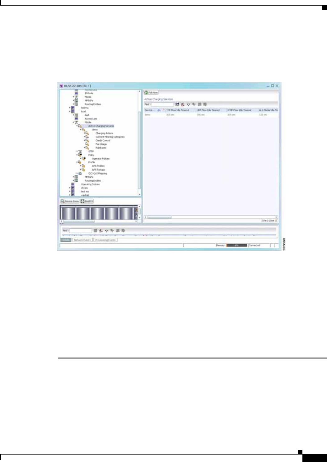
25-123
Cisco Prime Network 4.0 User Guide
OL-29343-01
Chapter 25 Monitoring Mobile Technologies Working with Active Charging Service
Viewing Active Charging Services
You can view the active charging services in logical inventory as shown in Figure 25-18.
Figure 25-18 Mobile Technology Setup Nodes
Additionally, you can also perform the following for each ACS:
• Viewing Content Filtering Categories, page 25-125
• Viewing Credit Control Properties, page 25-125
• Viewing Charging Action Properties
• Viewing Rule Definitions
• Viewing Rule Base for the Charging Action
• Viewing Bandwidth Policies
• Viewing Fair Usage Properties
To view ACS details in logical inventory:
Step 1 Right-click the required device in Prime Network Vision and choose Inventory.
Step 2 In the logical inventory window, choose Logical Inventory > local > Mobile > Active Charging
Services.
Prime Network Vision displays the list of active charging services configured under the container. You
can view the individual ACS details from the table on the right pane or by choosing Logical
Inventory > local > Mobile > Active Charging Services > ACS.
Table 25-75 describes the details available for each ACS.

25-124
Cisco Prime Network 4.0 User Guide OL-29343-01
Chapter 25 Monitoring Mobile Technologies
Working with Active Charging Service
Table 25-75 Active Charging Services in Logical Inventory
Field Description
Service Name Name of the active charging service.
TCP Flow Idle Timeout Maximum duration, in seconds, a TCP flow can remain idle.
UDP Flow Idle Timeout Maximum duration, in seconds, a UDP flow can remain idle.
ICMP Flow Idle
Timeout Maximum duration, in seconds, an Internet Control Message Protocol
(ICMP) flow can remain idle.
ALG Media Idle
Timeout Maximum duration, in seconds, an application level gateway (ALG) media
flow can remain idle.
TCP Flow Mapping Idle
Timeout
The time for which the TCP flow mapping timer holds the resources.
UDP Flow Mapping
Idle Timeout The time for which the UDP flow mapping timer holds the resources.
Deep Packet Inspection Indicates whether configuration of DPI is enabled or disabled in the mobile
video gateway.
Passive Mode Indicates whether the ACS is in or out of passive mode operation.
CDR Flow Control Indicates whether flow control is enabled or disabled between the ACS
Manager (ACSMGR) and Charging Data Record Module (CDRMOD).
CDR Flow Control
Unsent Queue Size Flow control unsent queue size at ACSMGR level.
Unsent Queue High
Watermark Highest flow control unsent queue size at ACSMGR level.
Unsent Queue Low
Watermark Lowest flow control unsent queue size at ACSMGR level.
Content Filtering Indicates whether content filtering is enabled or disabled for the ACS.
Dynamic Content
Filtering Indicates whether dynamic content filtering is enabled or disabled for the
ACS.
URL Blacklisting Indicates whether URL blacklisting is enabled or disabled for the ACS.
URL Blacklisting
Match Method Method to look up the URLs in the URL blacklisting database.
Content Filtering Match
Method Method to look up the URLs in the category-based content filtering database.
Interpretation of
Charging Rulebase
Name
Charging rulebase configured for the ACS.
Selected Charging
Rulebase Name for AVP Charging rulebase name for attribute value pair (AVP) configured for the
ACS.

25-125
Cisco Prime Network 4.0 User Guide
OL-29343-01
Chapter 25 Monitoring Mobile Technologies Working with Active Charging Service
Viewing Content Filtering Categories
To view content filtering categories in logical inventory:
Step 1 Right-click the required device in Prime Network Vision and choose Inventory.
Step 2 In the logical inventory window, choose Logical Inventory > local > Mobile > Active Charging
Services >ACS >Content Filtering Categories.
Prime Network Vision displays the list of content filtering categories configured under the container.
You can view the individual content filtering category details from the table on the right pane or by
choosing Logical Inventory > local > Mobile > Active Charging Services > ACS >Content Filtering
Categories > Content Filtering Category.
Table 25-76 describes the details available for each content filtering category.
Viewing Credit Control Properties
In a prepaid environment, the subscribers pay for a service prior to using it. While the subscriber is using
the service, credit is deducted from subscriber’s account until it is exhausted or the call ends. In prepaid
charging, ECS performs the metering function. Credits are deducted in real time from an account balance
or quota. A fixed quota is reserved from the account balance and given to the system by a prepaid rating
and charging server, which interfaces with an external billing system platform. The system deducts
Table 25-76 Content Filtering Categories in Logical Inventory
Field Description
Policy ID ID of the content filtering policy.
Failure Action Action to take for the content filtering analysis result.
EDR File The EDR file name.
Content Category Name of the content filtering category.
Content Insert Content string to insert in place of the message returned from prohibited or
restricted site or content server.
Content Priority Precedence of the category in the content filtering policy.
Content Failure Action Action to take for the indicated result of the content filtering analysis, which
could be one of the following:
• allow
• content-insert
• discard
• redirect URL
• terminate flow
• www-reply-code-and-terminate-flow
Content Redirect Content string to redirect the subscriber to a specified URL.
Content Reply Code Reply code to terminate flow.
EDR File Format Predefined EDR file format.

25-126
Cisco Prime Network 4.0 User Guide OL-29343-01
Chapter 25 Monitoring Mobile Technologies
Working with Active Charging Service
volume from the quota according to the traffic analysis rules. When the subscriber’s quota gets to the
threshold level specified by the prepaid rating and charging server, system sends a new access request
message to the server and server updates the subscriber's quota. The charging server is also updated at
the end of the call.
ECS supports the following credit control applications for prepaid charging:
• RADIUS Credit Control Application—RADIUS is used as the interface between ECS and the
prepaid charging server.
• Diameter Credit Control Application—The Diameter Credit Control Application (DCCA) is used to
implement real-time credit control for a variety of services, such as networks access, messaging
services, and download services.
To view credit control properties in logical inventory:
Step 1 Right-click the required device in Prime Network Vision and choose Inventory.
Step 2 In the logical inventory window, choose Logical Inventory > local > Mobile > Active Charging
Services >ACS > Credit Control.
Prime Network Vision displays the list of credit control groups configured under the container. You can
view the individual credit control group details from the table on the right pane or by choosing Logical
Inventory > local > Mobile > Active Charging Services > ACS > Credit Control > Credit Control
Group.
You can also view the following details by clicking the respective node under the credit control group:
• Diameter
• Failure Handling
• Pending Traffic Treatment
• Quota
• Server Unreachable Failure Handling
Table 25-77 describes the details available for each credit control group.
Table 25-77 Credit Control Properties in Logical Inventory
Field Description
Group Name of the credit control group for the subscriber.
Mode Prepaid charging application mode, which could be Diameter or Radius.
APN Name to be
Included Type of APN name sent in the credit control application (CCA) message.
Trigger Type Condition based on which credit reauthorization is triggered from the server.
Diameter MSCC Final
Unit Action Terminate Indicates whether to terminate a PDP session immediately when the
Final-Unit-Action (FUA) in a particular multi service credit control (MSCC)
is set as Terminate and the quota is exhausted for that service, or to terminate
the session after all MSCCs (categories) have used their available quota.
Diameter Peer Select table
Peer Primary hostname.
Realm Realm for the primary host.

25-127
Cisco Prime Network 4.0 User Guide
OL-29343-01
Chapter 25 Monitoring Mobile Technologies Working with Active Charging Service
Secondary Peer Secondary hostname.
Secondary Realm Realm for the secondary host.
IMSI Range Mode Mode of peer selection based on IMSI prefix or suffix.
IMSI Start Value Starting value of the IMSI range for peer selection.
IMSI End Value Ending value of the IMSI range for peer selection.
Diameter
End Point Name Name of the diameter endpoint.
End Point Realm Realm of the diameter endpoint.
Pending Timeout Maximum time to wait for response from a diameter peer.
Session Failover Indicates whether diameter session failover is enabled or not.
Dictionary Diameter credit control dictionary for the ACS.
Failure Handling
Initial Request Failure handling behavior, if failure takes place during initial session
establishment. Value could be continue, retry-and-terminate, and terminate.
Update Request Failure handling behavior, if failure takes place during update request. Value
could be continue, retry-and-terminate, and terminate.
Terminate Request Failure handling behavior, if failure takes place during terminate request.
Value could be continue, retry-and-terminate, and terminate.
Pending Traffic Treatment
Trigger Indicates whether to allow or drop a trigger while waiting for the credit
information from the server. Value could be pass or drop.
Forced Reauth Indicates whether to allow or drop reauthorization while waiting for the
credit information from the server. Value could be pass or drop.
NoQuota Indicates whether to allow or drop traffic, if there is no quota present. Value
could be pass, drop, or buffer.
Quota Exhausted Indicates whether to allow or drop traffic, if quota is exhausted. Value could
be pass, drop, or buffer.
Validity Expired Indicates whether to allow or drop traffic, if quota validity is expired. Value
could be pass or drop.
Quota
Request Trigger Action taken on the packet that triggers the credit control application to
request quota. Value could be exclude-packet-causing-trigger or
include-packet-causing-trigger.
Holding Time Duration for which ECS can hold the quota before returning to the credit
control server.
Validity Time Lifetime for which subscriber quota retrieved from the billing server is valid.
Time Threshold Time threshold limit for subscriber quota in the prepaid credit control
service.
Units Threshold Unit threshold limit for subscriber quota in the prepaid credit control service.
Table 25-77 Credit Control Properties in Logical Inventory (continued)
Field Description

25-128
Cisco Prime Network 4.0 User Guide OL-29343-01
Chapter 25 Monitoring Mobile Technologies
Working with Active Charging Service
Viewing Charging Action Properties
Charging Action is an action taken on the incoming data packets once the data packets are treated by the
routing and charging rule components. User can configure independent actions such as allow, forward,
and block traffic, and bind these actions with other routing and charging rule components.
To view charging action properties in logical inventory:
Step 1 Right-click the required device in Prime Network Vision and choose Inventory.
Step 2 In the logical inventory window, choose Logical Inventory > local > Mobile > Active Charging
Services >ACS > Charging Action.
Prime Network Vision displays the list of charging actions configured under the container as shown. You
can view the individual charging action details from the table on the right pane or by choosing Logical
Inventory > local > Mobile > Active Charging Services > ACS > Charging Action > Charging
Action.
You can also view the following details by clicking the respective node under the Charging Action node:
• Allocation Retention Priority
• Bandwidth
• Flow Action
• QoS
• Video
• Billing Action
Table 25-78 describes the details available for each charging action record.
Volume Threshold Volume threshold limit for subscriber quota in the prepaid credit control
service.
Server Unreachable Failure Handling
Initial Request Failure handling behavior if server is unreachable during initial session
establishment. Value could be continue or terminate.
Update Request Failure handling behavior if server is unreachable during update request.
Value could be continue or terminate.
Table 25-77 Credit Control Properties in Logical Inventory (continued)
Field Description
Table 25-78 Charging Action Properties in Logical Inventory
Field Description
Name Name of the charging action.
Content ID Content ID to use in the generated billing records as well the AVP used by
the credit control application.

25-129
Cisco Prime Network 4.0 User Guide
OL-29343-01
Chapter 25 Monitoring Mobile Technologies Working with Active Charging Service
Service ID Configured service ID used to associate the charging action in rule
definitions configuration.
Charging EDR Name Name of the EDR format for the billing action in the ACS.
EGCDRs Indicates whether eG-CDRs must be generated when the subscriber session
ends or an interim trigger condition occurs.
Rf Indicates whether Rf accounting is enabled or not.
UDRs Indicates whether UDRs must be generated based on the UDR format
declared in the rule base.
Flow Idle Timeout Maximum duration a flow can remain idle after which the system
automatically terminates the flow.
Limit for Flow Type
State Indicates whether the limit for flow type is configured or not.
Limit for Flow Type
Value Maximum number of flows of a particular type.
Limit for Flow Type
Action Action to be taken, if the number of flows exceeds the maximum limit.
IP Type of Service IP Type of Service (ToS) octets used in the charging action.
Retransmission Count Indicates whether to count the number of packet retransmissions when the
charging action is applied on the incoming data packets.
Content Filtering Indicates whether content filtering must be applied on the incoming packets
or not.
Credit Control Indicates whether to apply credit control or not.
Credit Rating Group Coupon ID used in prepaid charging as rating group.
Charge Volume Method used for charge volume calculation based on the protocol and
packet.
Next Hop Forwarding
Address Next hop forwarding address for a charging action.
VLAN ID VLAN ID configured for the subscriber
Flow Mapping Idle
Timeout Maximum duration, in seconds, a flow can remain idle after which the
system automatically terminates the flow.
Allocation Retention Priority
Priority Level Priority value that indicates whether to accept or reject a request for
establishment or modification of a bearer in a limited resource condition.
Priority Vulnerability
Indicator Defines whether an active bearer can be preempted by a preemption-capable
high priority bearer.
Priority Capability
Indicator Defines whether the bearer request can preempt the resources from the Low
Priority Pre-empatable Active Bearers.
Bandwidth
Bandwidth ID The bandwidth policy ID for the ACS.
Uplink Indicates whether uplink flow limit is configured for the subscriber or not.
Table 25-78 Charging Action Properties in Logical Inventory (continued)
Field Description

25-130
Cisco Prime Network 4.0 User Guide OL-29343-01
Chapter 25 Monitoring Mobile Technologies
Working with Active Charging Service
Downlink Indicates whether downlink flow limit is configured for the subscriber or not.
Charging Action Bandwidth Direction
Direction Direction of the packet flow: Uplink or Downlink
Peak Data Rate Peak data rate configured for the uplink or downlink packet flow.
Peak Burst Size Peak burst size allowed for the uplink or downlink packets.
Committed Data Rate Committed data rate for the uplink or downlink packet flow.
Committed Burst Size Committed burst size allowed for the uplink or downlink packets.
Exceed Action Action to take on packets that exceed committed data rate but do not violate
the peak data rate.
Violate Action Action to take on packets that exceed both committed and peak data rates.
Bandwidth Limiting ID Identifier for bandwidth limiting.
Flow Action
Redirect URL Indicates whether packets matched to the rule definition must be redirected
to a specified URL or not.
Clear Quota Retry
Timer Indicates whether to reset the CCA quota retry timer for a specific subscriber
upon redirection of data packets.
Conditional Redirect Indicates whether packets matching to a configured user agent must be
conditionally redirected to a specified URL.
Discard Discards packets associated with the charging action.
Random Drop Indicates whether to degrade voice quality and specify the time interval in
seconds at which the voice packets will be dropped.
Readdress Redirects unknown gateway traffic based on the destination IP address of the
packets to known or trusted gateways.
Terminate Flow Indicates whether to terminate the flow by terminating the TCP connection
gracefully between the subscriber and external server.
Terminate Session Indicates whether to terminate the session.
QoS
Traffic Class QoS traffic class for the charging action, which could be background,
conversational, interactive, or streaming.
Class Identifier The QCI value.
Video
Bit Rate Bits per second, at which the TCP video flow must be paced during video
pacing.
CAE Readdressing Indicates whether Content Adaptation Engine (CAE) readdressing is
enabled, allowing video traffic to be fetched from the CAEs in the CAE
group.
Transrating Indicates whether transrating is enabled or not. Transrating is a mobile video
feature that reduces the encoded bit rates by adjusting video encoding.
Target Rate Reduction Percentage of the input bit rate of a video flow.
Billing Action
Table 25-78 Charging Action Properties in Logical Inventory (continued)
Field Description

25-131
Cisco Prime Network 4.0 User Guide
OL-29343-01
Chapter 25 Monitoring Mobile Technologies Working with Active Charging Service
Viewing Rule Definitions
Rule definitions are user-defined expressions, based on protocol fields and protocol states, which define
what actions to take when specific field values are true. Each rule definition configuration consists of
multiple expressions applicable to any of the fields or states supported by the respective analyzers.
Rule definitions are of the following types:
• Routing—Used to route packets to content analyzers. Routing rule definitions determine which
content analyzer to route the packet to when the protocol fields and/or protocol states in the rule
definition expression are true. Up to 256 rule definitions can be configured for routing.
• Charging—Used to specify what action to take based on the analysis done by the content analyzers.
Actions can include redirection, charge value, and billing record emission. Up to 2048 charging rule
definitions can be configured in the system.
• Post-processing—Used for post-processing purposes. Enables processing of packets even if the rule
matching for them has been disabled.
• TPO—Used for Traffic Performance Optimization (TPO) in-line service match-rule and match
advertisement features.
To view rule definitions in logical inventory:
Step 1 Right-click the required device in Prime Network Vision and choose Inventory.
Step 2 In the logical inventory window, choose Logical Inventory > local > Mobile > Active Charging
Services > ACS > Rule Definitions.
Prime Network Vision displays the list of rule definitions configured under the container. You can view
the individual rule definition details from the table on the right pane or by choosing Logical
Inventory > local > Mobile > Active Charging Services >ACS > Rule Definitions > Rule Definition.
Table 25-79 describes the details available for each rule definition.
EDR Name of the EDR format for the billing action in the ACS.
EGCDR Indicates whether eG-CDRs must be generated when the subscriber session
ends or an interim trigger condition occurs.
Rf Indicates whether Rf accounting is enabled or not.
UDRs Indicates whether UDRs must be generated based on the UDR format
declared in the rule base.
Radius Accounting
Record Indicates whether radius accounting is enabled or not.
Table 25-78 Charging Action Properties in Logical Inventory (continued)
Field Description

25-132
Cisco Prime Network 4.0 User Guide OL-29343-01
Chapter 25 Monitoring Mobile Technologies
Working with Active Charging Service
Viewing Rule Definition Groups
A rule definition group enables grouping the rule definitions into categories. A rule definition group may
contain optimizable rule definitions. Whether a group is optimized or not is decided on whether all the
rule definitions in the group can be optimized. When a new rule definition is added, it is checked if it is
included in any rule definition group and whether it needs to be optimized or not.
To view rule definition groups in logical inventory:
Step 1 Right-click the required device in Prime Network Vision and choose Inventory.
Step 2 In the logical inventory window, choose Logical Inventory > local > Mobile > Active Charging
Services > ACS > Group of Rule Definitions.
Prime Network Vision displays the list of rule definition groups configured under the container. You can
view the individual rule definition group details from the table on the right pane or by choosing Logical
Inventory > local > Mobile > Active Charging Services >ACS > Group of Rule Definitions > Rule
Definition Group.
Table 25-79 Rule Definition Group Properties in Logical Inventory
Field Description
Name Name of the rule definition group.
Application Type Purpose of the rule definition, which could be charging, routing,
post-processing, or Traffic Performance Optimization (TPO).
Copy Packet To Log Indicates whether to copy every packet that matches the rule to a log file.
Tethered Flow Check Indicates whether tethered flow check if enabled or not. Tethering detection
flow check feature enables detection of subscriber data traffic flow
originating from PC devices tethered to mobile smart phones, and also
provides effective reporting to enable service providers take business
decisions on how to manage such usage and to bill subscribers accordingly.
Multiline OR Indicates whether to apply the OR operator to all lines in a rule definition.
This allows a single rule definition to specify multiple URL expressions.
Protocol Configuration
Protocol The protocol that this rule definition is applied on.
Fields Particular protocol field, which is applied on the data packets for inspection.
Value could be, host, payload, or domain.
Operator Logical operator that indicates how to logically match the value in the field
analyzed based on the data type.
Value Value of a particular protocol in a rule definition which has to be applied on
the incoming data packets for inspection.

25-133
Cisco Prime Network 4.0 User Guide
OL-29343-01
Chapter 25 Monitoring Mobile Technologies Working with Active Charging Service
Table 25-80 describes the details available for each rule definition group.
Rule Definition Group Commands
The following commands can be launched from the inventory by right-clicking a rule definition group
and choosing Commands > Configuration or Commands > Show. Before executing any commands,
you can preview them and view the results. If desired, you can also schedule the commands. To find out
if a device supports these commands, see the Cisco Prime Network 4.0 Supported Cisco VNEs.
Note You might be prompted to enter your device access credentials while executing a command. Once you
have entered them, these credentials will be used for every subsequent execution of a command in the
same GUI client session. If you want to change the credentials, click Edit Credentials. The Edit
Credentials button will not be available for SNMP commands or if the command is scheduled for a later
time.
Viewing Rule Base for the Charging Action
A rule base is a collection of rule definitions and their associated billing policy. The rule base determines
the action to be taken when a rule is matched. A maximum of 512 rule bases can be specified in the ECS
service. It is possible to define a rule definition with different actions.
Rule bases can also be used to apply the same rule definitions for several subscribers, which eliminate
the need to have unique rule definition for each subscriber. We can set priority, default bandwidth policy,
type of billing for subscriber sessions, for a rule definition/ group of rule definitions in the rule base.
Additionally we can configure content based billing and firewall/NAT constituent to rule base.
Table 25-80 Rule Definition Group Properties in Logical Inventory
Field Description
Name Name of the rule definition group.
Application Type Purpose of the rule definition group, which could be charging, routing,
content filtering, post-processing, or Traffic Performance Optimization
(TPO).
Dynamic Command
Content Filtering Policy
ID
Content filtering policy ID to add or remove dynamic commands from the
rule definition group.
Table 25-81 Rule Definition Group Commands
Command Type Command Inputs Required and Notes
Configuration Delete Group of RuleDefs Click Execute Now to delete the rule
definition group.
Show Show Group of RuleDefs Click Execute Now to display the group of
rule definitions.

25-134
Cisco Prime Network 4.0 User Guide OL-29343-01
Chapter 25 Monitoring Mobile Technologies
Working with Active Charging Service
To view a rule base in logical inventory:
Step 1 Right-click the required device in Prime Network Vision and choose Inventory.
Step 2 In the logical inventory window, choose Logical Inventory > local > Mobile > Active Charging
Services > ACS > Rulebase Container.
Prime Network Vision displays the list of rule bases configured under the container. You can view the
individual rule base details from the table on the right pane or by choosing Logical
Inventory > local > Mobile > Active Charging Services >ACS > Rulebase Container > Rule
Base.Table 25-82 describes the details available for each rule base record.
Table 25-82 Rule Base Properties in Logical Inventory
Field Description
Rulebase Name Name of the rule base.
Flow Any Error
Charging Action Charging action to be used for packets dropped due to any error conditions
after data session is created.
Limit for Total Flows Maximum number of simultaneous uplink and downlink packet flows.
Limit for TCP Flows Maximum number simultaneous TCP packet flows per subscriber or APN
allowed for a rulebase.
Limit for Non TCP
Flows Maximum number simultaneous non-TCP packet flows per subscriber or
APN allowed for a rulebase.
Charging Rule
Optimization Internal optimization level to use, for improved performance, when
evaluating each instance of the action.
QoS Renegotiation
Timeout Timeout value after which QoS renegotiation is performed.
RTP Dynamic Routing Indicates whether the Real Time Streaming Protocol (RTSP) and SDP
analyzers are enabled to detect the start/stop of RTP (a Transport Protocol
for Real-Time Applications) and RTP Control Protocol (RCP) flows.
Ignore Port Number In
Application Header Indicates whether to consider or ignore the port number embedded in the
application.
Delayed Charging Indicates how to charge for the control traffic associated with an application.
XHeader Certificate
Name Name of the encryption certificate to be used for x-header encryption.
XHeader Reencryption
Period Indicates how often to regenerate the encryption key for x-header
encryption.
Default Bandwidth
Policy Name of the default bandwidth policy per subscriber.
P2P Dynamic Routing Indicates whether P2P analyzer is enabled to detect the P2P applications
flow configured in ACS.
Fair Usage Waiver
Percentage Waiver percent on top of the average available memory credits per session
for the Fair Usage feature of active charging.
URL Blacklisting
Action Configured URL blacklisting action to take when the URL matches ones of
the blacklisted URLs.
URL Blacklisting
Content ID Specific content ID for which URL blacklisting is enabled in the rulebase.

25-135
Cisco Prime Network 4.0 User Guide
OL-29343-01
Chapter 25 Monitoring Mobile Technologies Working with Active Charging Service
Viewing Bandwidth Policies
Bandwidth policies are helpful in applying rate limit to potentially bandwidth intensive and service
disruptive applications. Using this policy, the operator can police and prioritize subscribers’ traffic to
ensure that no single or group of subscribers’ traffic negatively impacts another subscribers’ traffic. Each
policy will be identified by a unique ID, which will be associated to a particular group. Bandwidth
policies are used to control the direction (uplink/downlink) of bandwidth, peak data rate, and peak burst
size, and the actions that need to be taken on violation, if the bandwidth exceeds the burst size and data
rate.
To view bandwidth policy in logical inventory:
Step 1 Right-click the required device in Prime Network Vision and choose Inventory.
Step 2 In the logical inventory window, choose Logical Inventory > local > Mobile > Active Charging
Services > ACS > Bandwidth Policy Container.
Prime Network Vision displays the list of bandwidth policies configured under the container. You can
view the individual bandwidth policy details from the table on the right pane or by choosing Logical
Inventory > local > Mobile > Active Charging Services > ACS > Bandwidth Policy
Container > Bandwidth Policy.
Table 25-83 describes the details available for each bandwidth policy.
Charging Action
Priorities tab Charging rule definitions and their priorities in the rulebase.
Routing Action
Priorities tab Routing actions and their priorities in the rulebase.
Post Processing Action
Priorities Post-processing actions and their priorities in the rulebase.
Table 25-82 Rule Base Properties in Logical Inventory (continued)
Field Description
Table 25-83 Bandwidth Policy Properties in Logical Inventory
Field Description
Name Name of the bandwidth policy configured.
Total Bandwidth ID
Configured Total number of bandwidth IDs configured.
Total Group Limit
Configured Total number of bandwidth group limits configured.
Flow Limit for
Bandwidth ID and
Group ID Associations
and Group ID tables
Holds all bandwidth IDs and group IDs of the bandwidth policy.

25-136
Cisco Prime Network 4.0 User Guide OL-29343-01
Chapter 25 Monitoring Mobile Technologies
Working with Active Charging Service
Viewing Fair Usage Properties
To view fair usage properties configured for the ACS:
Step 1 Right-click the required device in Prime Network Vision and choose Inventory.
Step 2 In the logical inventory window, choose Logical Inventory > local > Mobile > Active Charging
Services > ACS > Fair Usage.
Prime Network Vision displays the details on the content pane.
Table 25-84 describes the fair usage properties.
ACS Commands
The following commands can be launched from the inventory by right-clicking an ACS and choosing
Commands > Configuration or Commands > Show. Before executing any commands, you can
preview them and view the results. If desired, you can also schedule the commands. To find out if a
device supports these commands, see the Cisco Prime Network 4.0 Supported Cisco VNEs.
The table below lists the ACS commands. Additional commands may be available for your devices. New
commands are often provided in Prime Network Device Packages, which can be downloaded from the
Prime Network software download site. For more information on how to download and install DPs and
enable new commands, see the information on “Adding Additional Device (VNE) support” in the Cisco
Prime Network 4.0 Administrator Guide.
Note You might be prompted to enter your device access credentials while executing a command. Once you
have entered them, these credentials will be used for every subsequent execution of a command in the
same GUI client session. If you want to change the credentials, click Edit Credentials. The Edit
Credentials button will not be available for SNMP commands or if the command is scheduled for a later
time.
Table 25-85 lists the Active Charging Services configuration commands.
Table 25-84 Fair Usage Properties in Logical Inventory
Field Description
CPU Threshold Percent Percentage of system CPU resources that the dynamic inline transrating
feature is allowed to use.
Threshold Percent Percentage of system resources that the dynamic inline transrating feature is
allowed to use.
Deactivate Margin
Percent Fair usage deactivate margin, below which monitor action is disabled.

25-137
Cisco Prime Network 4.0 User Guide
OL-29343-01
Chapter 25 Monitoring Mobile Technologies Working with Active Charging Service
Table 25-85 Active Charging Services Configuration Commands
Command Navigation Description
Create
Ruledef Expand Active Charging
Services node >
right-click ACS service >
Commands >
Configuration
Rule definitions (Ruledefs) are user-defined expressions,
based on protocol fields and/or protocol-states, which
define what actions to take when specific field values are
true.
Use this command to create a new rule definition for the
selected ACS service.
Create group
of Ruledefs Expand Active Charging
Services node >
right-click ACS service >
Commands >
Configuration
Group-of-Ruledefs enable grouping ruledefs into
categories. When a group-of-ruledefs is configured in a
rulebase, if any of the ruledefs within the group matches,
the specified charging-action is performed, any more
action instances are not.
Use this command to create a new group of rule
definitions for the selected ACS service.
Create
Rulebase Expand Active Charging
Services node >
right-click ACS service >
Commands >
Configuration
A rulebase is a collection of ruledefs and their associated
billing policy. The rulebase determines the action to be
taken when a rule is matched.
Use this command to create a new rule base for the
selected ACS service.
Modify
Active
Charging
Service
Delete Active
Charging
Service
Expand Active Charging
Services node >
right-click ACS service >
Commands >
Configuration
Use these commands to modify/delete an Active Charging
service created for the selected context.
Create
Access
Ruledef
Delete Access
Ruledef
Expand Active Charging
Services node >
right-click ACS service >
Commands >
Configuration > Access
Ruledef
Use these commands to create/delete an access rule
definition for the selected ACS service.
Show Access
Ruledef Expand Active Charging
Services node >
right-click ACS service >
Commands > Show
Use this command to view and confirm the access rule
definitions configured for the service.
Create Host
Pool
Modify Host
Pool
Delete Host
Pool
Expand Active Charging
Services node >
right-click ACS service >
Commands >
Configuration > Host
Pool
Host pools allow operators to group a set of host or IP
addresses that share similar characteristics together.
Access rule definitions (ruledefs) can be configured with
host pools. Up to ten sets of IP addresses can be
configured in each host pool.
Use these commands to create/modify/delete a host pool
for the selected ACS service.

25-138
Cisco Prime Network 4.0 User Guide OL-29343-01
Chapter 25 Monitoring Mobile Technologies
Mobile Technologies Commands: Summary
Mobile Technologies Commands: Summary
The following commands can be used to configure and view mobile technologies under a particular
context in the Prime Network Vision. These commands can be launched from the logical inventory by
choosing the Context > Commands > Configuration or Context > Commands > Show. Before
executing any command, you can preview them and view the results. If desired, you can also schedule
the commands. To find out if a device supports these commands, see the Cisco Prime Network 4.0
Supported Cisco VNEs.
The table below lists the commands to configure mobile technologies. Additional commands may be
available for your devices. New commands are often provided in Prime Network Device Packages,
which can be downloaded from the Prime Network software download site. For more information on
how to download and install DPs and enable new commands, see the information on “Adding Additional
Device (VNE) support” in the Cisco Prime Network 4.0 Administrator Guide.
Note You might be prompted to enter your device access credentials while executing a command. Once you
have entered them, these credentials will be used for every subsequent execution of a command in the
same GUI client session. If you want to change the credentials, click Edit Credentials. The Edit
Credentials button will not be available for SNMP commands or if the command is scheduled for a later
time.
Create
Charging
Action
Expand Active Charging
Services node >
right-click ACS service >
Commands >
Configuration
Charging Action is an action taken on the incoming data
packets once the data packets are treated by the routing
and charging rule components. You can configure
independent actions such as allow, forward, and block
traffic, and bind these actions with other routing and
charging rule components.
Use this command to configure a charging action for a
service.
Modify
charging
Action
Delete
Charging
Action
Expand Active Charging
Services node > ACS
service > Charging
Actions > right-click an
charging action >
Commands >
Configuration
Use these commands to modify/delete a charging action
for a service.
Show
Charging
Action
Expand Active Charging
Services node >
right-click ACS service >
Commands > Show
Use this command to view and confirm the charging
action configuration details.
Table 25-85 Active Charging Services Configuration Commands (continued)
Command Navigation Description

25-139
Cisco Prime Network 4.0 User Guide
OL-29343-01
Chapter 25 Monitoring Mobile Technologies Mobile Technologies Commands: Summary
Command Navigation Description
Create AAA
Group Context >
Commands >
Configuration
AAA refers to Authentication, Authorization, and Accounting,
which is a security architecture for distributed systems that
determines the access given to users for specific services and the
amount of resources they have used.
Use this command to create a new AAA group.
Create APN APN is the access point name that is configured in the GGSN
configurations.
Use this command to create a new APN service.
Create Active
Charging
Service
Enhanced Charging Service (ECS), also known as Active
Charging Service (ACS), is an in-line service, which is integrated
within the platform and provides mobile operators the ability to
offer tiered, detailed, and itemized billing to subscribers.
Use this command to create a new ACS service.
Create EGTP Evolved GPRS Tunneling Protocol (EGTP) formulates the
primary bearer plane protocol within an LTE / EPC architecture.
It provides support for tunnel management including handover
procedures within and across LTE networks.
Use this command to create an EGTP service.

25-140
Cisco Prime Network 4.0 User Guide OL-29343-01
Chapter 25 Monitoring Mobile Technologies
Mobile Technologies Commands: Summary
Create GGSN Context >
Commands >
Configuration
Gateway GPRS Support Node (GGSM) is the gateway between
the GPRS wireless data network and other external packet data
networks such as radio networks, IP networks, or private
networks. GGSN provides network access to external hosts
wishing to communicate with mobile subscribers (MS).
Use this command to create a GGSN service.
Create GTPP GPRS Tunneling Protocol Prime (GTPP) is used for
communicating accounting messages to CGs.
Use this command to create a GTPP service.
Create GTPU GTPU carries user data within the GPRS core network and
between the radio access network and the core network. The user
data transported can be packets in any of IPv4, IPv6, or PPP
formats.
Use this command to create a GTPU service.
Create IP Pool An IP pool is a sequential range of IP addresses within a certain
network.
Use this command to create an IP Pool.
Create P-GW PDN Gateway (P-GW) is the node that terminates the SGi
interface towards the PDN. If a UE is accessing multiple PDNs,
there may be more than one P-GW for that UE.
Use this command to create a P-GW.
Create
QCI-QOS
Mapping
The QoS Class Index (QCI) to QoS mapping configuration mode
is used to map QCIs to enforceable QoS parameters.
Use this command to create a QCI-QOS Mapping.
Create S-GW A Serving Gateway (S-GW) acts as a demarcation point between
the Radio Access Network (RAN) and core network, and
manages user plane mobility.
Use this command to create a S-GW.
Create VRF Virtual routing and forwarding (VRF) is a technology included in
IP (Internet Protocol) network routers that allows multiple
instances of a routing table to exist in a router and work
simultaneously.
Use this command to create a VRF.
Delete Context Use this command to delete a context under the Logical Inventory
node.
Modify
License Use this command to modify the license information.
Command Navigation Description

25-141
Cisco Prime Network 4.0 User Guide
OL-29343-01
Chapter 25 Monitoring Mobile Technologies Mobile Technologies Commands: Summary
Create DHCP Context >
Commands >
Configuration >
DHCP
DHCP is used to automate host configuration by assigning IP
addresses, delegating prefixes (in IPv6), and providing extensive
configuration information to network computers.
Use this command to create a DHCP service.
Delete DHCP Use this command to delete a DHCP service.
Modify DHCP Use this command to modify the configuration details of a DHCP
service.
Create HA SPI
List Context >
Commands >
Configuration >
HA SPI List
Use this command to create the Security Parameter Index (SPI)
between the HA service and the FA.
Delete HA SPI
List Use this command to delete the HA SPI List.
Modify HA
SPI List Use this command to modify the HA SPI List configuration
details.
Create HA
Service Context >
Commands >
Configuration >
HA Service
Use this command to create a new Home Agent service.
Delete HA
Service Use this command to delete a HA Service.
Modify HA
Service Use this command to modify the configuration details of a HA
service.
Create
Network
Requested
PDP Context
Context >
Commands >
Configuration >
PDP Context
Packet Data Protocol (PDP) context is the connection or link
between a mobile device and a network server that allows them
to communicate with each other. A PDP context lasts only for the
duration of a specific connection.
Use this command to create a network requested PDP context.
Delete
Network
Requested
PDP Context
Use this command to delete a network requested PDP context.
Create Proxy
DNS Context >
Commands >
Configuration >
Proxy DNS
The proxy DNS listens for incoming DNS requests on the local
interface and resolves remote hosts using an external PHP script,
through http proxy requests.
Use this command to create a proxy DNS.
Delete Proxy
DNS Use this command to delete a proxy DNS.
Modify Proxy
DNS Use this command to modify the proxy DNS configuration
details.
Command Navigation Description

25-142
Cisco Prime Network 4.0 User Guide OL-29343-01
Chapter 25 Monitoring Mobile Technologies
Mobile Technologies Commands: Summary
Create Route
Access List Context >
Commands >
Configuration >
Route Map and
Route Access
List
Access lists are a set of rules, organized in a rule table and are
used to filter and identify traffic.
Use this command to create a new access list.
Create Route
Map Route maps are similar to access lists; they both have criteria for
matching the details of certain packets and an action of
permitting or denying those packets. Unlike access lists, though,
route maps can add to each "match" criterion a "set" criterion that
actually changes the packet in a specified manner, or changes
route information in a specified manner.
Use this command to create a route map.
Delete Route
Access List Use this command to delete a route access list.
Delete Route
Map Use this command to delete a route map.
Modify Route
Access List Use this command to modify a route access list.
Modify Route
Map Use this command to modify a route map.
Create
Subscribers Context >
Commands >
Configuration >
Subscriber
Use this command to create a new subscriber.
Delete
Subscriber Use this command to delete a subscriber.
Modify
Subscriber Use this command to modify subscriber details.
Show APN Context >
Commands >
Show
Use this command to view and confirm the APN configuration
details.
Show DHCP Use this command to view and confirm the DHCP configuration
details.
Show EGTP Use this command to view and confirm the EGTP configuration
details.
Show HA SPI
List Use this command to view and confirm the HA SPI List details.
Show HA
Service Use this command to view and confirm the home agent service
details.
Show IP Pool Use this command to view and confirm the IP Pool configuration
details.
Show License Use this command to view and confirm the License details.
Show Route
Access List Use this command to view and confirm the Access list details.
Show Route
Map Use this command to view and confirm the Route Map details.
Show
Subscriber Use this command to view and confirm the Subscriber details.
Command Navigation Description

25-143
Cisco Prime Network 4.0 User Guide
OL-29343-01
Chapter 25 Monitoring Mobile Technologies Monitoring the Mobility Management Entity
Monitoring the Mobility Management Entity
Mobility Management Entity (MME) is the key control-node for an LTE access network, which works
in conjunction with NodeB(eNodeB), Serving Gateway, or the LTE/SAW core network. It is responsible
for initiating paging and authentication of mobile devices. It keeps location information at the Tracking
Area Level for each user and chooses the right gateway during the initial registration process.
The MME uses the SSI-MME interface to connect to an eNode and uses the S11interface to connect to
a S-GW. In case there is an increase in the signalling load in the network, you can group multiple MMEs
in a pool to meet this load. It ia also the termination point in the network for ciphering/integrity
protection for NAS signaling.
MME supports lawful interception of signaling and provides the control plane function for mobility
between LTE and 2G/3G access networks with the S3 interface terminating at the MME from the SGSN.
It also terminates the S6a interface towards the home HSS for roaming UEs.
Create Policy
Accounting Right-click on
context >
Commands >
Configuration >
Policy
Accounting
Use this command to create a new accounting policy.
Modify Policy
Accounting
Delete Policy
Accounting
Right-click on
context >
Commands >
Configuration >
Policy
Accounting
Use these commands to modify/delete an accounting policy.
Command Navigation Description
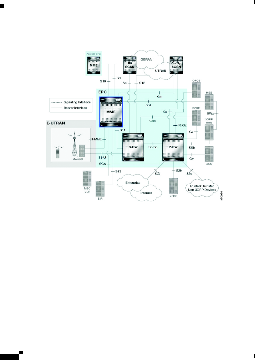
25-144
Cisco Prime Network 4.0 User Guide OL-29343-01
Chapter 25 Monitoring Mobile Technologies
Monitoring the Mobility Management Entity
Figure 25-19 depicts the topology of the LTE network along with MME:
Figure 25-19 MME Topology
The different features of the MME are listed below:
• Involved in bearer activation/deactivation
• Provides P-GW selection to the subscriber to connect to PDN
• Tracks the UE for idle mode and paging procedures, including transmissions
• Chooses the S-GW for a UE during initial attach and also at the time of intra-LTE handover
involving Core Network node relocation
• Authenticates the user (by interacting with the HSS)
• Works as a termination point for Non-Access Stratum (NAS) signaling
• Generates and allocates temporary identities to the UEs
• Checks whether the UE is authorized to camp on the service provider’s Public Land Mobile Network
(PLMN)
• Enforces UE roaming restrictions
• Handles security key management
• Communicates with other MMEs in the same or different PLMN
There are many different MME interfaces, which are listed below:

25-145
Cisco Prime Network 4.0 User Guide
OL-29343-01
Chapter 25 Monitoring Mobile Technologies Monitoring the Mobility Management Entity
• S1-MME Interface—The interface used by MME to communicate with eNodeBs on the same
PLMN. This interface is the reference point for the control plane protocol between eNodeB and
MME, this interface uses the S1 Application Protocol (SI-AP) instead of the Stream Control
Transmission Protocol (SCTP) as the transport layer protocol for guaranteed delivery of signaling
messages between MME and eNodeB. It serves as a path for establishing and maintaining subscriber
UE contexts and supports IPv4, IPv6, IPSec, and multi-homing.
• S3 Interface—The interface used by MME to communicate with S4-SGSNs on the same PLMN for
interworking between GPRS/UMTS and LTE network technologies. This interface serves as a
signaling path for establishing and maintaining subscriber UE contexts. The MME communicates
with SGSNs on the PLMN using the GPRS Tunneling Protocol (GTP). The signaling or control
aspect of this protocol is referred to as the GTP Control Plane (GTPC) while the encapsulated user
data traffic is referred to as the GTP User Plane (GTPU). One or more S3 interfaces can be
configured per system context.
• S6a Interface—The interface used by MME to communicate with Home Subscriber Server (HSS)
on PLMN using the diameter protocol. This interface is responsible for transfer of subscription and
authenticating or authorizing user access and UE context.
• S10 Interface—The interface used by the MME to communicate with another MME on the same or
a different PLMN using the GTPv2 protocol. This interface is also used for MME relocation and
MME-to-MME information transfer or handoff
• S11 Interface—The interface used by the MME to communicate with Serving Gateways (S-GW) for
transfer of information, using the GTPv2 protocol.
• S13 Interface—The interface used by the MME to communicate with the Equipment Identity
Register (EIR).
• SGs Interface—The interface used to connect the databases in the VLR and MME to support circuit
switch fallback scenarios.
• Sv Interface—The interface used by the MME to connect to the Mobile Switching Center to support
exchange of messages during a handover procedure for the Single Radio Voice Call Continuity
(SRVCC) feature.
• Gn Interface—The interface used to facilitate user mobility between 2G and 3G 3GPP networks.
This interface is used for intra-PLMN handovers.
• SLg Interface—The interface used by MME to communicate with the Gateway Mobile Location
Ceter (GMLC) using the diameter protocol. This interface is used for the Location Services (LCS),
which enables the system to determine and report location information of the connected UEs.
Viewing the MME Configuration Details
To view the MME configuration details:
Step 1 Right-click the required device in Prime Network Vision and choose Inventory.
Step 2 In the logical inventory window, choose Logical Inventory > Context > Mobile > MME. The list of
MME services configured in Prime Network is displayed in the content pane.
Step 3 From the MME node, choose an MME service. The MME service details are displayed in the content
pane as shown in Figure 25-20.
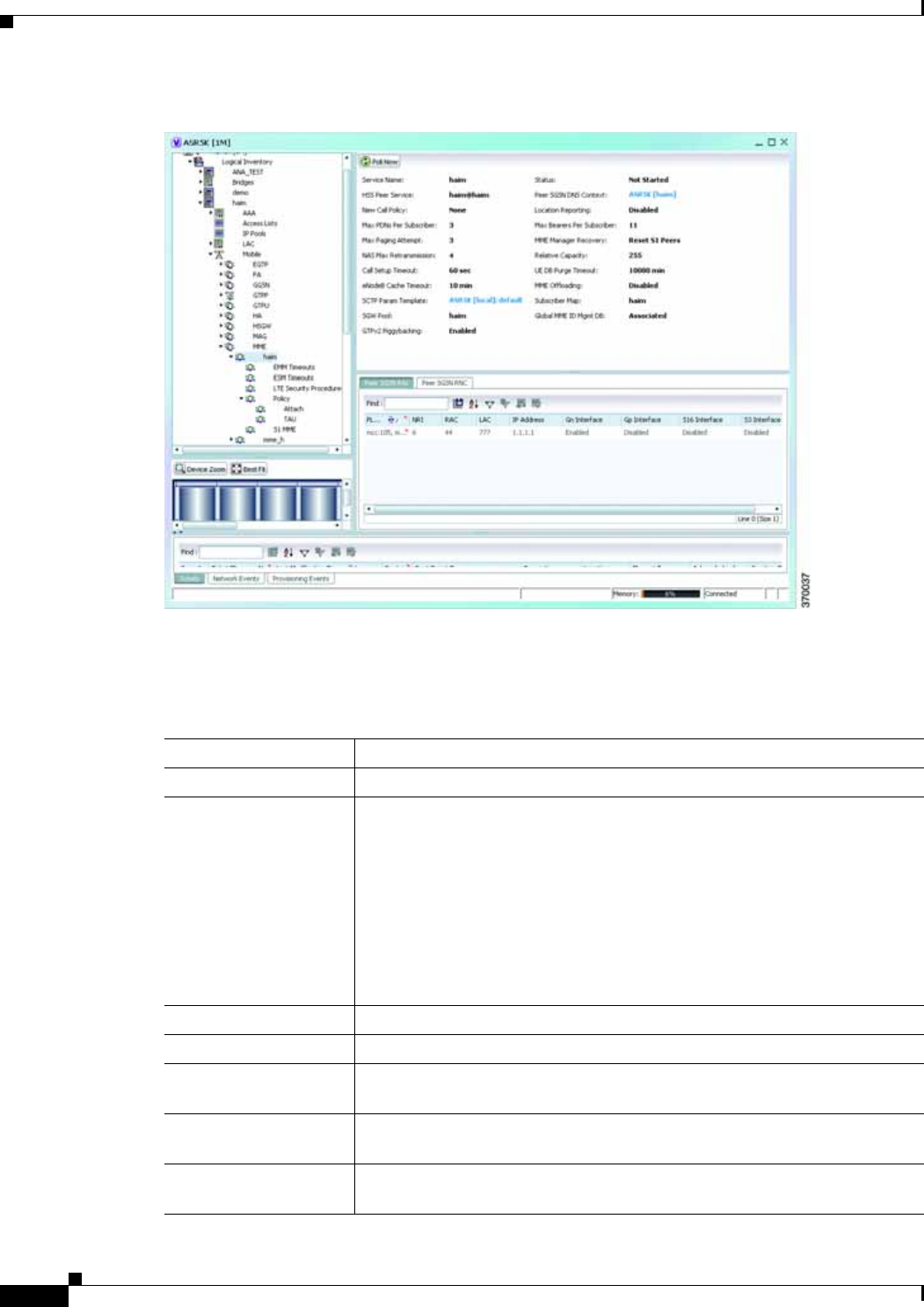
25-146
Cisco Prime Network 4.0 User Guide OL-29343-01
Chapter 25 Monitoring Mobile Technologies
Monitoring the Mobility Management Entity
Figure 25-20 MME Configuration Details
Table 25-86 displays the MME service details.
Table 25-86 MME Service Details
Field Description
Service Name The unique name of the MME service.
Status The status of the MME service, which can be any one of the following:
• Unknown
• Initiated
• Running
• Down
• Started
• Not Started
MME Group ID The unqiue ID of the group to which the MME service belongs to.
MME Code The unique code for the MME service.
EGTP Service The name of the EGTP peer service associated with the MME service, which
is pre-configured for the selected context.
HSS Peer Service The name of the HSS peer service associated with the MME service, which
is pre-configured for the selected context.
SGTPC Service The name of the SGTPC peer service associated with the MME service,
which is pre-configured for the selected context.

25-147
Cisco Prime Network 4.0 User Guide
OL-29343-01
Chapter 25 Monitoring Mobile Technologies Monitoring the Mobility Management Entity
SGS Service The name of the SGS peer service associated with the MME service, which
is pre-configured for the selected context.
Peer MME DNS
Context The DNS client service that is used to query and select a peer MME. The
peer MME is then associated with the MME service to be used for
inter-MME handovers.
Peer SGSN DNS
Context The DNS client service that is used to query and select a peer SGSN. The
peer SGSN is then associated with the MME service to be used for inter-RAT
handovers.
PGW DNS Context The DNS client that is used to query and select a P-GW to be associated with
the MME service.
SGW DNS Context The DNS client that is used to query and select a S-GW to be associated with
the MME service.
LTE Emergency Profile The LTE emergency profile for the MME service. This profile helps the
MME service to create an emergency session for a subscriber who is not part
of the network. A maximum of four such profiles can be created.
Subscriber Map The unique name of the subscriber map that is pre-configured for the MME
service.
SGW Pool The Serving Gateway (SGW) Pool that is communicating with the MME
service. This pool is configued by associating the Tracking Area Identity
(TAI) Management Database to the MME service.
MSC IP Address The IP address of the Mobile Switching Center (MSC) that is linked to the
MME service.
MSC Port The unique MSC port for the MME service.
New Call Policy Indicates whether the new call policy feature is enabled. The new call policy
is executed when duplicate sessions with the same IP address request is
received.
Location Reporting Indicates whether the UE location reporting feature is enabled for the MME
service.
Max PDNs Per
Subscriber The maximum number of PDNs that can be accessed by a subscriber
simultaneously using the MME service.
Max Bearer Per
Subscriber The maximum number of EPS bearers that can be used by a subscriber
simultaneously to access the MME service.
Max Paging Attempt The maximum number of times a subscriber can attempt to create network
requested service, after failure at the first attempt.
NAS Max
Retransmission The maximum number of times NAS messages can be retransmitted for the
MME service.
Relative Capacity The relative capacity variable that is sent to the eNodeB to select an MME
in order to load balance the pool.
Call Setup Timeout The timeout duration (in seconds) for setting up MME calls in the MME
service.
Table 25-86 MME Service Details (continued)
Field Description

25-148
Cisco Prime Network 4.0 User Guide OL-29343-01
Chapter 25 Monitoring Mobile Technologies
Monitoring the Mobility Management Entity
UE DB Purge Timeout The amount of time (in minutes) after which the User Equipment is attached
to the MME service and reuses the previously established security
parameters.
Note The UE database is maintained by the MME as a cache of the EPS
context for each UE. This cache is maintained in each session
manager where the UE was attached first.
eNodeB Cache Timeout The timeout duration (in minutes) for the eNodeB Cache. This field defaults
to 10.
MME Offloading Indicates whether the MME offloading feature is enabled.
Note You must configure the load balancing parameters beforehand. For
example, if you want to remove all existing subscribers from the
MME and route new entrants to the pool area, then you must specify
the weight as zero.
Global MMEID
MgmtDB The global MME ID management database for the MME service.
GTPv2 Piggy Bagging Indicates whether the GTPv2 piggy backing feature is enabled.
Note The MME service sends a piggy backing flag to a P-GW to
determine if the dedicated bearer creation is piggy backed onto the
message.
NRI tab
PLMN Id The PLMN ID of the MME service.
Note This code is made up of the Mobile Country Code (MCC) and
Mobile Network Code (MNC). You can configure a maximum of 16
PLMN IDs for an MME service.
Length (bits) The number of bits in the Packet domain Temporary Mobile Subscriber
Identity (P-TMSI) to be used as the Network Resource Identifier (NRI).
PGW Address tab
IP Address The IP address of the PDN Gateway (P-GW).
Note The P-GW address is used to configure P-GW discovery and it uses
TP/P-MIP protocol for S5 and S8 interface and other parameters
with MME service.
S5 S8 Protocol The P-MIP protocol type to be used for S5 and S8 interfaces. By default, the
GTP protocol is used for these interfaces.
Table 25-86 MME Service Details (continued)
Field Description

25-149
Cisco Prime Network 4.0 User Guide
OL-29343-01
Chapter 25 Monitoring Mobile Technologies Monitoring the Mobility Management Entity
Weight The weightage assigned to a P-GW address, which indicates the address that
must be used as the preferred P-GW. This weight can be any value between
1 and 100 and the address with the lowest values indicates the least preferred
address.
Peer MME GUMMEI tab
MME ID The unique MME ID of the peer MME.
PLMN ID The PLMN ID of the peer MME service.
Group ID The unique ID of the group to which the peer MME services belongs to.
IP Address The IPv4 address of the peer MME.
Peer MME TAI tab
MME ID The unique MME ID of the peer MME.
PLMN ID The PLMN ID of the peer MME service.
TAC The Tracking Area Code (TAC) of the peer MME service.
IP Address The IPv4 address of the peer MME.
Peer SGSN RAI tab
PLMN ID The PLMN ID of the peer MME service.
NRI The Network Resource Identifier (NRI) code used to identify Peer SGSN for
support of 3G to 4G handover capability.
RAC The Routing Area Code (RAC) of the peer SGSN service.
LAC The Location Area Code (LAC) of the peer SGSN service.
IP Address The IPv4 address of the peer SGSN service.
Gn Interface Indicates whether the peer SGSN service is allowed to communicate over the
Gn Interface.
Gp Interface Indicates whether the peer SGSN service is allowed to communicate over the
Gp Interface.
S16 Interface Indicates whether the peer SGSN service is allowed to communicate over the
S16 Interface.
S3 Interface Indicates whether the peer SGSN service is allowed to communicate over the
S3 Interface.
Peer SGSN RNC
PLMN ID The PLMN ID of the peer MME service.
RNC The Radio Network Controller (RNC) of the peer SGSN service.
IP Address The IPv4 to IPv6 address of the peer SGSN service.
Gn Interface Indicates whether the peer SGSN service is allowed to communicate over the
Gn Interface.
Gp Interface Indicates whether the peer SGSN service is allowed to communicate over the
Gp Interface.
Table 25-86 MME Service Details (continued)
Field Description

25-150
Cisco Prime Network 4.0 User Guide OL-29343-01
Chapter 25 Monitoring Mobile Technologies
Monitoring the Mobility Management Entity
You can also view the following configurations for a MME service:
• EMM Timeouts—EPS Mobility Management (EMM) is used to support the mobility of a user
equipment. For example, it informs the network of the UEs current location and provides user
identity confidentiality. Apart from these services, it also provides connection management services
to the session management sublayer and defines timer parameters such as timeout durations for
retransmission of NAS messages.
• ESM Timeouts—EPS Session Management (ESM) is used to provide subscriber session
management for bearer context activation, deactivation, modification and update procedures.
• LTE Security Procedures—The LTE integrity and encryption algorithms used for security
procedures for the MME service, which are enabled by default.
• Policy—The session management policies for LTE subscribers of the MME service.
• S1 Interface—Transfer of signalling messages between the MME service and the eNodeB. S1 MME
uses the S1 Application Protocol (S1-AP) over the Steam Control Transmission Protocol (SCTP).
This interface also serves as a path for establishing and maintaining subscriber EPS bearer context.
Viewing the EMM Configuration Details
To view the EMM configuration details for a MME service:
Step 1 Right-click the required device in Prime Network Vision and choose Inventory.
Step 2 In the logical inventory window, choose Logical Inventory > Context > Mobile > MME > MME
service > EMM. The EMM configuration details are displayed in the content pane.
Table 25-87 displays the EMM configuration details.
S16 Interface Indicates whether the peer SGSN service is allowed to communicate over the
S16 Interface.
S3 Interface Indicates whether the peer SGSN service is allowed to communicate over the
S3 Interface.
Table 25-86 MME Service Details (continued)
Field Description
Table 25-87 EMM Configuration Details
Field Description
Implicit Detach
Timeouts The timeout duration (in seconds) after which the subscriber will be
detached from the network in case there is no activity. This time can be any
value between 1 and 12000, and defaults to 5640.
Mobile Reachable
Timeout The timeout duration (in seconds) after which the attempt to reach the
network is discarded and the reattempt procedure starts. This time can be any
value between 1 and 12000, and defaults to 5640.

25-151
Cisco Prime Network 4.0 User Guide
OL-29343-01
Chapter 25 Monitoring Mobile Technologies Monitoring the Mobility Management Entity
Viewing the ESM Configuration Details
To view the ESM configuration details for a MME service:
Step 1 Right-click the required device in Prime Network Vision and choose Inventory.
Step 2 In the logical inventory window, choose Logical Inventory > Context > Mobile > MME > MME
service > ESM. The ESM configuration details are displayed in the content pane.
Table 25-88 displays the ESM configuration details.
T3412 Timeout The timeout duration (in seconds) for the T3412 timer, which is used for
periodic tracking area update (P-TAU). This time can be any value between
1 and 11160, and defaults to 5400. When this timer expires, the periodic
tracking area update procedure starts and the timer is reset for the next start.
T3413 Timeout The timeout duration (in seconds) for the T3413 timer, which starts when the
MME service initiates the EPS paging procedure and requests the lower
layer to start paging. When the UE responds to the procedure, then the timer
stops the paging procedure. This time can be any value between 1 and 20,
and defaults to 10.
T3422 Timeout The timeout duration (in seconds) for the T3422 timer, which starts when the
MME initiates the detach procedure (by sending a Detach Request message)
to the UE. On receipt of a Detach Accept message from the UE, the timer
stops. This time can be any value between 1 and 20, and defaults to 10.
T3423 Timeout The timeout duration (in seconds) for the T3423 timer, which starts when the
UE is in the EMM-Deregistered state or enters the EMM-Connected mode.
This timer stops when the UE gets back to the EMM-Registered state. This
time can be any value between 1 and 11160, and defaults to 5400.
T3450 Timeout The timeout duration (in seconds) for the T3450 timer, which starts when the
MME initiates the Globally Unique Temporary Identifier (GUTI)
reallocation procedure by sending the GUTI-Reallocation Command
message to the UE. The timer stops when the GUTI-Reallocation Complete
message is received. This time can be any value between 1 and 20, and
defaults to 6.
T3460 Timeout The timeout duration (in seconds) for the T3460 timer, which starts when the
network initiates the authentication procedure by sending the
Authentication Request to the UE. The timer stops on receipt of a
Authentcation Response message from the UE. This time can be any value
between 1 and 20, and defaults to 6.
T3470 Timeout The timeout duration (in seconds) for the T3470 timer, which starts when the
network initiates the identification procedure by sending an Identity
Request message to the UE. This timer stops on receipt of a Identity
Response message from the UE. This time can be any value between 1 and
20, and defaults to 6.
Table 25-87 EMM Configuration Details (continued)
Field Description

25-152
Cisco Prime Network 4.0 User Guide OL-29343-01
Chapter 25 Monitoring Mobile Technologies
Monitoring the Mobility Management Entity
Viewing the LTE Security Procedure Configuration Details
To view the LTE security procedure configuration details for a MME service:
Step 1 Right-click the required device in Prime Network Vision and choose Inventory.
Step 2 In the logical inventory window, choose Logical Inventory > Context > Mobile > MME > MME
service > LTE Security Procedure. The configuration details are displayed in the content pane.
Table 25-89 displays the LTE security procedure configuration details.
Table 25-88 ESM Configuration Details
Field Description
T3485 Timeout The timeout duration (in seconds) for the T3485 timer, which is used to
activate the default EPS Bearer context. The timer starts when the MME
sends the Activate Default EPS Bearer Context Request message to the
UE. The timer stops when it receives the either the Activate Default EPS
Bearer Context Accept or Activate Default EPS Bearer Context Reject
message. This time can be any value between 1 and 60, and defaults to 6.
T3486 Timeout The timeout duration (in seconds) for the T3485 timer, which is used to
modify the default EPS Bearer context. The timer starts when the MME
sends the Modify EPS Bearer Context Request message to the UE. The
timer stops when it receives the either the Modify EPS Bearer Context
Accept or Modify EPS Bearer Context Reject message. This time can be
any value between 1 and 60, and defaults to 6.
T3489 Timeout The timeout duration (in seconds) for the T3489 timer, which is used to
deactivate the default EPS Bearer context. The timer starts when the MME
sends the ESM Information Request message to the UE. The timer stops
when it receives the ESM Information Response message. This time can be
any value between 1 and 60, and defaults to 4.
T3495 Timeout The timeout duration (in seconds) for the T3495 timer, which is used to
deactivate the default EPS Bearer context. The timer starts when the MME
sends the Deactivate EPS Bearer Context Request message to the UE. The
timer stops when it receives the either the Deactivate EPS Bearer Context
Accept or Deactivate EPS Bearer Context Reject message. This time can
be any value between 1 and 60, and defaults to 6.

25-153
Cisco Prime Network 4.0 User Guide
OL-29343-01
Chapter 25 Monitoring Mobile Technologies Monitoring the Mobility Management Entity
Viewing the MME Policy Configuration Details
To view the policy configuration details for a MME service:
Step 1 Right-click the required device in Prime Network Vision and choose Inventory.
Step 2 In the logical inventory window, choose Logical Inventory > Context > Mobile > MME > MME
service > Policy > Attach. The policy configuration details are displayed in the content pane.
Table 25-90 displays the Policy configuration details.
Table 25-89 LTE Security Procedure Configuration Details
Field Description
Encryption Algorithm
Priority 1 The encryption algorithm that must be treated as the first priority for security
procedures on the MME service, which can be any one of the following
values:
• 128-eea0—Null Ciphering Algorithm
• 128-eea1—SNOW 3G synchronous stream ciphering algorithm
• 128-eea2—Advance Encryption Standard (AES) ciphering algorithm
Encryption Algorithm
Priority 2 The encryption algorithm that must be treated as the second priority for
security procedures on the MME service, which can be any one of the
following values:
• 128-eea0—Null Ciphering Algorithm
• 128-eea1—SNOW 3G synchronous stream ciphering algorithm
• 128-eea2—Advance Encryption Standard (AES) ciphering algorithm
Encryption Algorithm
Priority 3 The encryption algorithm that must be treated as the third priority for
security procedures on the MME service, which can be any one of the
following values:
• 128-eea0—Null Ciphering Algorithm
• 128-eea1—SNOW 3G synchronous stream ciphering algorithm
• 128-eea2—Advance Encryption Standard (AES) ciphering algorithm
Integrity Algorithm
Priority 1 The integrity algorithm that must be treated as the first priority for security
procedures on the MME service, which can be any one of the following
values:
• 128-eia1—SNOW 3G synchronous stream ciphering algorithm
• 128-eia2—Advance Encryption Standard
Integrity Algorithm
Priority 2 The integrity algorithm that must be treated as the second priority for
security procedures on the MME service, which can be any one of the
following values:
• 128-eia1—SNOW 3G synchronous stream ciphering algorithm
• 128-eia2—Advance Encryption Standard

25-154
Cisco Prime Network 4.0 User Guide OL-29343-01
Chapter 25 Monitoring Mobile Technologies
Monitoring the Mobility Management Entity
Viewing the S1 Interface Configuration Details
To view the S1 Interface configuration details for a MME service:
Step 1 Right-click the required device in Prime Network Vision and choose Inventory.
Step 2 In the logical inventory window, choose Logical Inventory > Context > Mobile > MME > MME
service > S1 Interface. The interface configuration details are displayed in the content pane.
Table 25-91 displays the S1 Interface configuration details.
Table 25-90 Policy Configuration Details
Field Description
IMEI Query type The type of IMEI query use for attaching the user equipment and tracking
area update procedure,which can be any one of the following:
• imei (International Mobile Equipment Identity)
• imei-sv (International Mobile Equipment Identity-Software Version)
Set UE Time Indicates whether the MME serivce must set the time in the UE during the
attach or tracking area update procedure.
Deny Grey Listed Indicates whether the MME service must deny the grey listed equipment. In
other words, it specifies whether the identification of the UE must be
performed by the Equipment Identity Register (EIR) over the S13 interface.
Deny Unknown Indicates whether the MME service must deny service to an unknown
equipment.
Verify Emergency Indicates whether the MME service must verify the equipment for
emergency calls.
Allow On ECA Timeout Indicates whether the MME service must allow service of equipements that
timeout on the ECA.
EIR Query Type Indicates whether querying of EIR is enabled or disabled.
Table 25-91 S1 Interface Configuration Details
Field Description
Primary IP Address The IP address (IPv4 or IPv6) of the interface configured as an S1-MME
interface.
Secondary IP Address The optional IP address (IPv4 or IPv6) of the interface configured as an
S1-MME interface.
SCTP Port The source SCTP port used for binding the SCTP socket to communicate
with the eNodeB. This port can be any value between 1 and 65535, and
defaults to 699.
Max Subscribers The maximum number of subscribers that can access the MME service on
the interface. This number can be any value between 0 and 4,000,000.

25-155
Cisco Prime Network 4.0 User Guide
OL-29343-01
Chapter 25 Monitoring Mobile Technologies Viewing the Stream Control Transmission Protocol
Viewing the Stream Control Transmission Protocol
The Stream Control Transmission Protocol (SCTP) is a message oriented, reliable transport protocol
with direct support for multihoming that runs on top of Internet Protocol (IPv4/IPv6). Like TCP, SCTP
provides reliable, connection-oriented data delivery with congestion control, path MTU discovery and
message fragmentation.
Its role is similar to the roles of popular protocols such as Transmission Control Protocol (TCP) and User
Datagram Protocol (UDP). It provides some of the same service features of both: it is message-oriented
like UDP and ensures reliable, in-sequence transport of messages with congestion control like TCP.
SCTP offers the following services to the users:
• Acknowledged error-free non-duplicated transfer of user data
• Data fragmentation to conform to discovered path MTU size
• Sequenced delivery of user messages within multiple streams, with an option for order-of-arrival
delivery of individual user messages
QoS DSCP The Quality of Service (QoS) Differentiated Service Code Point (DSCP)
used when sending data packets (of a particular 3GPP QoS class) over the
S1-MME interface. Ths can be any one of the following values:
• af11
• af12
• af13
• af21
• af22
• af23
• af31
• af32
• af33
• af41
• af42
• af43
• be
• ef
Crypto Template The name of the crypto template that is used when implementing IP Security
on the S1-MME interface.
S1 Interface Connected
Trap Indicates whether the SNMP trap for the S1 interface connection equipment
is enabled.
Table 25-91 S1 Interface Configuration Details (continued)
Field Description

25-156
Cisco Prime Network 4.0 User Guide OL-29343-01
Chapter 25 Monitoring Mobile Technologies
Viewing the Stream Control Transmission Protocol
• Optional bundling of multiple user messages into a single SCTP packet
• Network-level fault tolerance through supporting of multi-homing at either or both ends of an
association
The SCTP application submits data to be transmitted in messages to the SCTP transport layer. The
messages and control information is separated and placed in chunks (data and control chunks), each
identified by a chunk header. A message can be fragmented over a number of data chunks, but each data
chunk contains data from only one user message. SCTP bundles the chunks into SCTP packets, which
are then submitted to the Internet Protocol. The SCTP packet consists of a packet header, SCTP control
chuck (if required) and SCTP data chunks (if available).
The primary distinguishing features of this new protocol are:
• multi-homing—The ability of an association to support multiple IP addresses or interfaces at a given
endpoint. Currently, SCTP does not do load-sharing, but with the multi-homing facility, SCTP has
greater potential to survive a session in case of network failures. Using more than one address allows
re-routing of packets in event of failure and also provides an alternate path for retransmissions.
Endpoints can exchange lists of addresses during initiation of the association. One address is
designated as the primary address to receive data. A single port number is used across the entire
address list at an endpoint for a specific session. Heartbeat chunks are used to monitor availability
of alternate paths with thresholds set to determine failure of alternate and primary paths.
Note An “association here refers to the connection between two endpoints in this context.
• multi-streaming—Each stream represents a sequence of messages within a single association. These
messages may be long or short, which include flags for control of segmentation and reassembly.
Stream Identifiers and Stream Sequence numbers are included in the data packet to allow sequencing
of messages on a per-stream basis. This ensures that unnecessary head-of-line blocking between
independent streams of messages is avoided in case of loss in one stream.
SCTP also provides a mechanism for designating order-of-arrival delivery as opposed to ordered
delivery. The design of SCTP includes appropriate congestion avoidance behavior and resistance to
flooding and masquerade attacks.
In case of ASR 5000 devices, SCTP carries signalling traffic that flows through IPSec tunnel over LTE
S1-MME interface.
To view the SCTP configuration details:
Step 1 Right-click the required device in Prime Network Vision and choose Inventory.
Step 2 In the logical inventory window, choose Logical Inventory > Context > Profile > SCTP Template. A
list of SCTP templates is displayed in the content pane.
Step 3 In the Logical Inventory window, select a template from the SCTP Template node. The SCTP template
details are displayed in the content pane as shown in Figure 25-21.
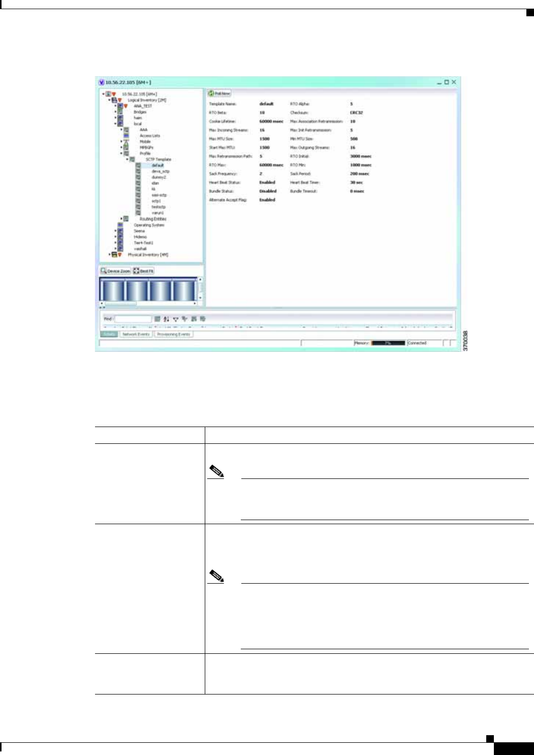
25-157
Cisco Prime Network 4.0 User Guide
OL-29343-01
Chapter 25 Monitoring Mobile Technologies Viewing the Stream Control Transmission Protocol
Figure 25-21 SCTP Template Details
Table 25-92 describes the SCTP Template details.
Table 25-92 SCTP Template Details
Field Description
Template Name The unique name of the SCTP template.
Note Each template can be configured with different values and
associated to different services such as the MME service, diameter
endpoint and so on.
RTO Alpha The Retransmission Timeout (RTO) alpha (smoothing factor) value that is
used to calculate Smooth Round Trip Time (SRTT) and the Round Trip Time
Variation (RTTVAR) for new Round Trip Time (RTT) measurements.
Note RTO refers to the amount of time to wait before transmitting a
package from the retransmission queue to the neighbor. SRTT refers
to the amount of time (in milliseconds) it takes for a packet to be sent
to the neighbor and for the local router to receive an
acknowledgement for the packet.
RTO Beta The Retransmission Timeout (RTO) beta (delay variance factor) value that is
used to calculate Smooth Round Trip Time (SRTT) and the Round Trip Time
Variation (RTTVAR) for new Round Trip Time (RTT) measurements.

25-158
Cisco Prime Network 4.0 User Guide OL-29343-01
Chapter 25 Monitoring Mobile Technologies
Viewing the Stream Control Transmission Protocol
Checksum The type of checksum that is used to increase data integrity of the SCTP
packets, which can be any one of the following:
• adler32—the Adler-32 checksum algorithm is used
• crc32—the 32 bit cyclic redundancy check algorithm is used.
Cookie Lifetime The lifetime (in milliseconds) of the SCTP cookie.
Max Association
Retransmission The maximum number of retransmissions allowed by this template for the
SCTP associations.
Max Incoming Streams The maximum number of incoming SCTP streams.
Max Init
Retransmissions The maximum number of SCTP initiation retransmissions.
Max MTU Size The maximum size (in bytes) of the Maximum Transmission Unit (MTU) for
SCTP streams.
Min MTU Size The minimum size (in bytes) of the MTU for SCTP streams.
Start Max MTU The starting size (in bytes) of the MTU for SCTP streams.
Max Outgoing Streams The maximum number of outgoing SCTP streams.
Max Retransmissions
Path The maximum number of retransmissions of the SCTP paths.
RTO Initial The initial time (in milliseconds) for retransmission of SCTP packets.
RTO Max The maximum time (in miliseconds) for retransmission of SCTP packets.
RTO Min The minimum time (in milliseconds) for transmission of SCTP packets.
SACK Frequency The frequency of the Selective Acknowledgement (SACK) of the SCTP
packets.
SACK Period The period (in milliseconds) of selective acknowledgement of the SCTP
packets.
Heart Beat Status Indicates whether the option to send traffic over an alternate path, in case of
a path failure, is enabled.
Note The Heartbeat message is sent to a peer endpoint to probe the
reachability of a particular destination transport address defined in
the present association. If the address is not reachable, the traffic is
sent over an alternate address. If this option is enabled, then the
failover recovery is not even known to the user.
Heart Beat Timer The amount of time (in seconds) to wait before a peer is is considered
unreachable. When a Heartbeat request is sent and if an acknowledgement is
not received before this timer, then subsequent heartbeat requests are not
sent and the peer is considered unreachable.
Bundle Status Indicates whether the data chunks must be bundled into packets before
submitting to the IP. If this option is disabled, then the packets are sent
without bundling.
Table 25-92 SCTP Template Details (continued)
Field Description

25-159
Cisco Prime Network 4.0 User Guide
OL-29343-01
Chapter 25 Monitoring Mobile Technologies Viewing the Stream Control Transmission Protocol
Bundle Timeout The amount of time (in seconds) after which the chunks of SCTP packets are
bundled and committed for transmission.
Alternate Accept Flag Indicates whether the alternate accept flag that denotes additional lifetime
for the association, is enabled.
Table 25-92 SCTP Template Details (continued)
Field Description

25-160
Cisco Prime Network 4.0 User Guide OL-29343-01
Chapter 25 Monitoring Mobile Technologies
Viewing the Stream Control Transmission Protocol

CHAPTER
26-1
Cisco Prime Network 4.0 User Guide
OL-29343-01
26
Monitoring Data Center Configurations
Data Center is a centralized repository, either physical or virtual for the storage, management,
dissemination of data and information organized around a particular manner. In other words, it is a
facility used to house computer systems and associated components, such as telecommunications and
storage systems. It generally includes redundant or backup power supplies, redundant data
communication connections, environmental controls such as air conditioning or fire suppression, and
security devices.
Cisco Prime Network supports the following network elements as part of data centers:
Table 26-1 Devices supported as part of Data Center
Device Type Device
Physical Network Devices Cisco Nexus 1010 network element
Cisco Nexus 2000 network element
Cisco Nexus 3000 network element
Cisco Nexus 5000 network element
Cisco Nexus 7000 network element
Cisco ASA 5500
Cisco Catalyst 6500 Virtual Switching System
Cisco Catalyst 6500 FWSM
Cisco Catalyst 6500 ACE 20
Cisco Catalyst 6500 ACE 30
Cisco MDS 9500
Cisco MDS 9100
Cisco Unified Computing System (UCS 6100 and
6200)
Cisco Compute Servers UCS Chassis (UCS 5100)
UCS Blade (UCS B Series)
UCS Blade (UCS C Series)
Virtual Network Devices Nexus 1000v
Cloud Service Router CRS1000v
Virtual Security Gateway (VSG)

26-2
Cisco Prime Network 4.0 User Guide OL-29343-01
Chapter 26 Monitoring Data Center Configurations
User Roles Required to Work with Data Center Configurations
Prime Network supports the following technologies as part of data center:
• Virtual Port Channel (vPC), page 26-3
• Cisco FabricPath, page 26-7
• Virtualization, page 26-11
• Viewing the Storage Area Network Support Details, page 26-37
User Roles Required to Work with Data Center Configurations
Table 26-2 identifies the GUI default permission or device scope security level that is required to work
with Prime Network Vision. Prime Network Vision determines whether you are authorized to perform a
task as follows:
• For GUI-based tasks (tasks that do not affect devices), authorization is based on the default
permission that is assigned to your user account.
• For element-based tasks (tasks that do affect elements), authorization is based on the default
permission that is assigned to your account. That is, whether the element is in one of your assigned
scopes and whether you meet the minimum security level for that scope.
For more information on user authorization, see the Cisco Prime Network 4.0 Administrator Guide.
By default, users with the Administrator role have access to all managed elements. To change the
Administrator user scope, see the topic on device scopes in the Cisco Prime Network 4.0 Administrator
Guide.
Non Cisco Servers Dell Blade Server
IBM Blade Server (PowerEdge Servers)
IBM Blade Server (Intel Servers)
Table 26-1 Devices supported as part of Data Center (continued)
Device Type Device
Table 26-2 Default Permission/Security Level Required for the Data Center Configurations
Task Viewer Operator OperatorPlus Configurator Administrator
Viewing Virtual Port
Channel Configuration XXXXX
Viewing vPC
Configuration XXXXX
Viewing Cisco
FabricPath
Configuration
XXXXX
Monitoring Cisco
FabricPath
Configuration
XXXXX
Viewing Virtual Data
Centers XXXXX

26-3
Cisco Prime Network 4.0 User Guide
OL-29343-01
Chapter 26 Monitoring Data Center Configurations Virtual Port Channel (vPC)
Virtual Port Channel (vPC)
A Virtual Port Channel (vPC) allows links that are physically connected to two different
Cisco Nexus 7000 or Cisco Nexus 5000 series network elements to appear as a single port channel by a
third device as shown in Figure 26-1. The third device can be a switch, server, or any other networking
device that supports port channels. A vPC can provide Layer 2 multipathing, which allows you to create
redundancy and increase bisectional bandwidth by enabling multiple parallel paths between nodes and
allowing load balancing traffic. You can use only Layer 2 port channels in the vPC.
Viewing the Data Stores
of a Data Center XXXXX
Viewing the Host
Servers of a Data Center X1X1X1X1X1
Viewing the Virtual
Machines of a Data
Center
X1X1X1X1X1
Viewing Host Cluster
Details X1X1X1X1X1
Viewing Resource Pool
Details X1X1X1X1X1
Viewing the Map Node
for an UCS Network
Element
XXXXX
Viewing the Virtual
Network Devices of a
Data Center
X1X1X1X1X1
Viewing the Compute
Server Support Details X1X1X1X1X1
Viewing the Storage
Area Network Support
Details
X1X1X1X1X1
Monitoring the
Compute Services
Search Capability
XXXXX
1. For users to be able to view VMs and hypervisors, a user's device scope must include all relevant vCenter VNEs.
Table 26-2 Default Permission/Security Level Required for the Data Center Configurations
Task Viewer Operator OperatorPlus Configurator Administrator
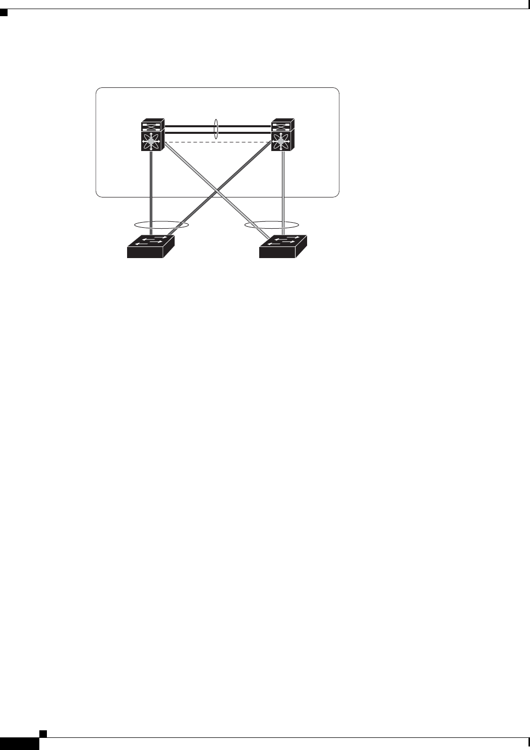
26-4
Cisco Prime Network 4.0 User Guide OL-29343-01
Chapter 26 Monitoring Data Center Configurations
Virtual Port Channel (vPC)
Figure 26-1 vPC Architecture
A vPC consists of the following components:
• Two vPC peer switches, among which one is primary and one is secondary. The system formed by
the two peer switches is referred to as a vPC domain.
• A peer link, also known as multichassis EtherChannel trunk (MCT), which connects the vPC peer
switches. A peer link is a redundant 10 Gigabit Ethernet Port Channel,which is used to carry traffic
from one system to the other when needed and to synchronize forwarding tables.
• vPC member ports that form the PortChannel and are split between the vPC peers.
• A routed link, called as a vPC peer-keepalive or fault-tolerant link is a Layer 3 Gigabit Ethernet link,
used to resolve dual-active scenarios where the peer link connectivity is lost.
A vPC domain is associated to a single Virtual Device Context (VDC), so all vPC interfaces belonging
to a given vPC domain must be defined in the same VDC. You must have a separate vPC peer link and
peer keepalive link infrastructure for each VDC deployed. Consolidating a vPC pair (two vPC peer
devices of the same domain) in two VDCs of the same physical device is not supported. The vPC peer
link must use 10-Gigabit Ethernet ports for both ends of the link; otherwise, the link will not be formed.
A vPC provides the following benefits:
• Allows a single device to use a port channel across two upstream devices
• Eliminates STP blocked ports
• Provides a loop-free topology
• Uses all available uplink bandwidth
• Provides fast convergence in case of link or a device failure
• Provides link level resiliency
• Assures high availability
Prime Network supports vPC on Cisco Nexus 5000 series and Cisco Nexus 7000 series network
elements.
This topic contains the following sections:
• Viewing Virtual Port Channel Configuration, page 26-5
• Viewing vPC Configuration, page 26-7
vPC peer link
273225
Nexus 7000
device
Nexus 7000
device
vPC
device
vPC
device
vPC domain
Peer-keepalive link
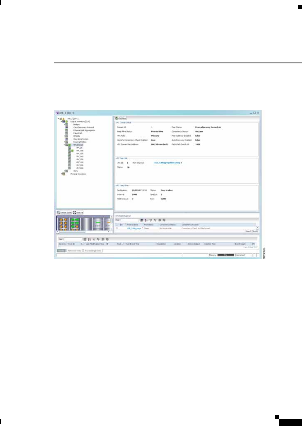
26-5
Cisco Prime Network 4.0 User Guide
OL-29343-01
Chapter 26 Monitoring Data Center Configurations Virtual Port Channel (vPC)
Viewing Virtual Port Channel Configuration
To view the vPC configuration details in Prime Network Vision:
Step 1 Right-click on the required device and choose the Inventory option.
Step 2 In the Inventory window, choose Logical Inventory > VPC Domain. The vPC domain details are
displayed in the content pane as shown in Figure 26-2.
Figure 26-2 vPC Domain in Logical Inventory
Table 26-3 describes the vPC domain details.

26-6
Cisco Prime Network 4.0 User Guide OL-29343-01
Chapter 26 Monitoring Data Center Configurations
Virtual Port Channel (vPC)
Table 26-3 vPC Domain Properties
Field Name Description
Domain ID Unique ID that is used to identify the vPC peer links and ports connected
to the vPC downstream devices.
Peer Status Status of the peer link.
Keep Alive Status Status of the keep alive link, which could be Alive or Down.
Consistency Status Consistency status of the vPC, which could be Success or Failed.
vPC Role Role of the vPC, which could be Primary or Secondary.
Peer Gateway Enabled Status of the peer gateway, which could be Enabled or Disabled.
Graceful Consistency
Check Enabled Indicates whether graceful consistency check is enabled or disabled.
This consistency check helps in preventing traffic drops.
Auto Recovery Enabled Indicates whether auto recovery is enabled or disabled.
vPC Domain Mac
Address MAC address of the vPC domain.
FabricPath Switch ID ID of the FabricPath switch connected to the vPC.
vPC Peer Link
vPC ID Unique ID for vPC peer link.
Status Status of the port channel used for communication, which could be Up
or Down.
Port Channel vPC used as the port channel for communication. Click the hyperlink, to
view the relevant Ethernet link aggregation node in the physical
inventory.
vPC Keep Alive
Destination Destination IP address of the peer switch.
Status Status of the keep alive link, which could be Alive or Down.
Interval Interval time required to check whether the peer switch is active or
inactive.
Timeout Time taken by the peer switch to respond.
Hold Timeout Amount of time during which the peer switch information is stored.
Port Interface used for the communication.
VPC Port Channel
vPC ID Unique virtual Port Channel ID.
Port Channel Ethernet link used as the port channel for communication. Click the
hyperlink, to view the relevant Ethernet link aggregation node in the
physical inventory.
Port Status Status of the vPC, which could be Up or Down.
Consistency Status Consistency status of the vPC, which could be Success or Failed.
Consistency Reason Reason for the consistency status.

26-7
Cisco Prime Network 4.0 User Guide
OL-29343-01
Chapter 26 Monitoring Data Center Configurations Cisco FabricPath
Viewing vPC Configuration
The following commands can be launched from the inventory by right-clicking VPC Domain and
choosing Commands > Show. The table below lists vPC show commands.
Additional commands may be available for your devices. New commands are often provided in Prime
Network Device Packages, which can be downloaded from the Prime Network software download site.
For more information on how to download and install DPs and enable new commands, see the
information on “Adding Additional Device (VNE) support” in the Cisco Prime Network 4.0
Administrator Guide.
Before executing any commands, you can preview them and view the results. If desired, you can also
schedule the commands. To find out if a device supports these commands, see the Cisco Prime Network
4.0 Supported Cisco VNEs.
Note You might be prompted to enter your device access credentials while executing a command. Once you
have entered them, these credentials will be used for every subsequent execution of a command in the
same GUI client session. If you want to change the credentials, click Edit Credentials. The Edit
Credentials button will not be available for SNMP commands or if the command is scheduled for a later
time.
Cisco FabricPath
Cisco FabricPath is an innovation in Cisco NX-OS software that brings the stability and scalability of
routing to Layer 2. It provides a foundation to build a scalable fabric—a network that itself looks like a
single virtual switch from the perspective of its users. The switched domain does not have to be
segmented anymore, providing data center–wide workload mobility. Because traffic is no longer
forwarded along a spanning tree, the bisectional bandwidth of the network is not limited, and massive
scalability is possible.
Cisco FabricPath introduces an entirely new Layer 2 data plane by encapsulating the frames entering the
fabric with a header that consists of routable source and destination addresses. These addresses are the
address of the switch on which the frame was received and the address of the destination switch to which
the frame is heading. From there, the frame is routed until it is reaches the remote switch, where it is
de-encapsulated and delivered in its original Ethernet format.
Command Navigation Description
Show Port Channel
Capacity Right-click on the VPC node >
Commands > Show Use this command to view and confirm
the port channel capacity details.
Show vPC Use this command to view the vPCs
available for the selected domain.
Show vPC Consistency
Parameters Use this command to view the vPC
consistency parameters.
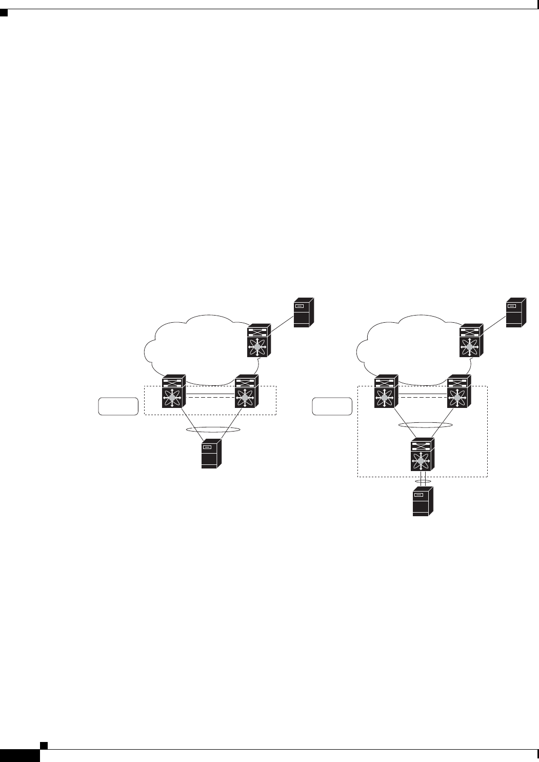
26-8
Cisco Prime Network 4.0 User Guide OL-29343-01
Chapter 26 Monitoring Data Center Configurations
Cisco FabricPath
Cisco FabricPath provides the following features:
• Allows Layer 2 multipathing in the FabricPath network.
• Provides built-in loop prevention and mitigation with no need to use the Spanning Tree Protocol
(STP).
• Provides a single control plane for unknown unicast, broadcast, and multicast traffic.
• Enhances mobility and virtualization in the FabricPath network.
The system randomly assigns a unique switch ID to each device that is enabled with FabricPath. After
you enable FabricPath on the devices, you can configure an Ethernet interface or a port channel interface
as a FabricPath interface. If one member of the port channel is in FabricPath mode, then all the other
members will also be in FabricPath mode. After you configure the interface as a FabricPath interface, it
automatically becomes a trunk port, capable of carrying traffic for multiple Virtual Local Area Networks
(VLANs).
Prime Network supports Cisco FabricPath on Cisco Nexus 5000 series and Cisco Nexus 7000 series
network elements. Figure 26-3 shows a Cisco FabricPath architecture.
Figure 26-3 Cisco FabricPath Architecture
This topic contains the following sections:
• Viewing Cisco FabricPath Configuration, page 26-9
• Monitoring Cisco FabricPath Configuration, page 26-10
279717
FP network
S3
B
CE
S1 S2
A
CE
FP network
S3
B
CE
S1 S2
A
CE
S4
vPC vPC+
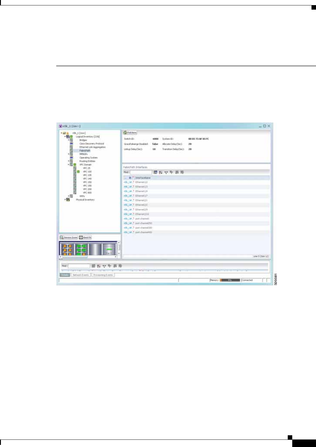
26-9
Cisco Prime Network 4.0 User Guide
OL-29343-01
Chapter 26 Monitoring Data Center Configurations Cisco FabricPath
Viewing Cisco FabricPath Configuration
To view the FabricPath configuration in Prime Network Vision:
Step 1 Right-click on the required device and choose the Inventory option.
Step 2 In the Inventory window, choose Logical Inventory > FabricPath. The FabricPath configuration
details are displayed in the content pane as shown in Figure 26-4. You can also view the properties, by
right-clicking the FabricPath node and choosing Properties.
Figure 26-4 Cisco FabricPath Node in Logical Inventory
Table 26-4 describes the FabricPath configuration details.

26-10
Cisco Prime Network 4.0 User Guide OL-29343-01
Chapter 26 Monitoring Data Center Configurations
Cisco FabricPath
Monitoring Cisco FabricPath Configuration
The following commands can be launched from the inventory by right-clicking FabricPath and
choosing Commands > Show.
The table below lists FabricPath configuration commands. Additional commands may be available for
your devices. New commands are often provided in Prime Network Device Packages, which can be
downloaded from the Prime Network software download site. For more information on how to download
and install DPs and enable new commands, see the information on “Adding Additional Device (VNE)
support” in the Cisco Prime Network 4.0 Administrator Guide.
Before executing any commands, you can preview them and view the results. If desired, you can also
schedule the commands. To find out if a device supports these commands, see the Cisco Prime Network
4.0 Supported Cisco VNEs.
Note You might be prompted to enter your device access credentials while executing a command. Once you
have entered them, these credentials will be used for every subsequent execution of a command in the
same GUI client session. If you want to change the credentials, click Edit Credentials. The Edit
Credentials button will not be available for SNMP commands or if the command is scheduled for a later
time.
Table 26-4 Cisco FabricPath Configuration
Field Name Description
Switch ID Unique ID of the Cisco FabricPath virtual switch.
System-ID System MAC address of the Cisco FabricPath.
Gracefulmerge
Disabled Indicates whether graceful merge feature is enabled are not. Value could
be True or False. If this feature is enabled, the switch would be
effectively linked to the Cisco FabricPath network. If disabled, you may
experience traffic drops.
Allocate Delay (sec) Time delay during new resource propagation.
Linkup Delay (sec) Time delay for detecting conflicts during linkup sessions.
Transition Delay (sec) Time delay during transition of value propagation.
FabricPath Interfaces
Port Ethernet link, which is configured as a Cisco FabricPath. Click the
hyperlink to view the interface link in physical inventory.
Interface Name Name of the interface for which switch port mode is configured as a
Cisco FabricPath.

26-11
Cisco Prime Network 4.0 User Guide
OL-29343-01
Chapter 26 Monitoring Data Center Configurations Virtualization
Virtualization
Virtualization is a concept of creating a virtual version of any resource, such as hardware platform,
operating system, storage device, or network resources, as shown in Figure 26-5. It provides a layer of
abstraction between computing, storage and networking hardware, and the applications running on it.
Virtual infrastructure gives administrators the advantage of managing pooled resources across the
enterprise, allowing IT managers to be more responsive to dynamic organizational needs and to better
leverage infrastructure investments.
The VMware vCenter Server provides centralized management of virtualized hosts and virtual machines
from a single console. With VMware vCenter Server, virtual environments are easier to manage: a single
administrator can manage hundreds of workloads, more than doubling typical productivity in managing
physical infrastructure.
In Prime Network, VCenter is modelled as a VNE.
Note VCenter is created as a separate VNE using the Cisco Prime Network Administration application. For
more information about creating a new VNE, see the Cisco Prime Network 4.0 Administrator Guide. You
must specify the http credentials for VCenter. However, the SNMP credentials are optional.
Figure 26-5 Virtualization Concept
Command Navigation Description
FabricPath Conflict Right-click on the FabricPath
node > Commands > Show Use this command to view the
Cisco FabricPath conflicts.
MAC Address-Table
Learning Mode Use this command to view the MAC
address-table learning mode.

26-12
Cisco Prime Network 4.0 User Guide OL-29343-01
Chapter 26 Monitoring Data Center Configurations
Virtualization
The various components of virtualization are:
Hypervisor (Host Server)
A hypervisor, also called a blade server, a virtual machine manager, or a host server, is a program that
allows multiple operating systems to share a single hardware host. Each operating system appears to
have the host's processor, memory, and other resources all to itself. However, the hypervisor is actually
controlling the host processor and resources, allocating what is needed to each operating system in turn
and making sure that the guest operating systems (called virtual machines) do not disrupt each other.
Virtual Machine
A virtual representation of a real machine using software that provides an operating environment, which
can run or host a guest operating system.
Guest Operating System
An operating system running in a virtual machine environment that would otherwise run directly on a
separate physical system.
Data Store
A data store represents a storage location for virtual machine files. It can be a Virtual Machine File
System (VMFS) volume, a directory on Network Attached Storage, or a local file system path.
Data Center
Data Center serves as a container for hosts, virtual machines, networks, and data stores.
Cluster
A cluster is a collection of servers that operate as if it is a single machine. The primary purpose of these
clusters is to provide uninterrupted access to data, even if a server loses network or storage connectivity,
or fails completely, or if the application running on the server fails.
Resource Pool
A resource pool is a logical abstraction for flexible management of resources. Resource pools can be
grouped into hierarchies and used to hierarchically partition available CPU and memory resources.It is
the foundation of virtual data centers, virtual desktops, high availability and other options on virtual
servers. Resource pools aggregate CPU processing power and memory, along with any other relevant
components, then share these hardware resources among virtual machines (VMs).
The following topics explain how to view and monitor virtual data center properties in
Prime Network Vision:
• Viewing Virtual Data Centers, page 26-13
• Viewing the Data Stores of a Data Center, page 26-13
• Viewing the Host Servers of a Data Center, page 26-14
• Viewing all the Virtual Machines managed by vCenter, page 26-18
• Viewing the Virtual Machines of a Data Center, page 26-19
• Viewing the Host Cluster Details, page 26-22
• Viewing the Resource Pool Details, page 26-24

26-13
Cisco Prime Network 4.0 User Guide
OL-29343-01
Chapter 26 Monitoring Data Center Configurations Virtualization
Viewing Virtual Data Centers
To view the virtual data centers in the logical inventory:
Step 1 Right-click on the required device and choose the Inventory option.
Step 2 In the Inventory window, choose Logical Inventory > Compute Virtualization. The virtual data
centers are listed in the content pane.
Table 26-5 describes the virtual data center properties.
Step 3 Right-click on a data center and choose Properties to view more details.
Viewing the Data Stores of a Data Center
To view the details of data stores available for a data center:
Step 1 Right-click on the required device and choose the Inventory option.
Step 2 In the Inventory window, choose Logical Inventory > Compute Virtualization > Data Center > All
Data Stores. The available data stores are displayed in the content pane. You can view the data store
properties from the table or by right-clicking the required data store and choosing Properties.
Table 26-6 describes the data store properties.
Table 26-5 Virtual Data Center Properties
Field Name Description
Name Name of the data center.
IP Address IP address of the vCenter, which manages the virtual data center.
DNS name The DNS name of the data center.

26-14
Cisco Prime Network 4.0 User Guide OL-29343-01
Chapter 26 Monitoring Data Center Configurations
Virtualization
Viewing the Host Servers of a Data Center
To view the host centers of a data center:
Step 1 Right-click on the required device and choose the Inventory option.
Step 2 In the Inventory window, choose Logical Inventory > Compute Virtualization > Data Center > All
Host Servers. Choose a host server and the details are displayed in the content pane as shown in
Figure 26-6.
Table 26-6 Data Store Properties
Field Name Description
Name Name of the data store.
Storage Type Type of data storage for the data store.
Capacity Capacity of the data store, in GB.
Free Space Free space of the data store, in GB.
Provisioned Space The amount of provisioned space available for the data store.
Accessible Indicates whether the data store is accessible or not. Value could be True
or False.
Multi Host Access Indicates whether the data store supports multi host access. Value could
be True or False.
Storage Location The location of the data store.
Uuid The unique ID of the data store.
Associated storage
device The storage device associated to the data store.
Connected Hosts
Host Name The name of the host connected to the data store.
Associated Host The link to the associated host, which when clicked will take you to the
relevant host node.
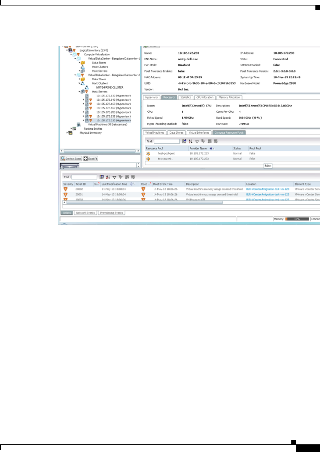

26-16
Cisco Prime Network 4.0 User Guide OL-29343-01
Chapter 26 Monitoring Data Center Configurations
Virtualization
Table 26-7 Host Servers of a Data Center
Field Name Description
Name Name of the host server.
IP Address The IP address of the host server.
DNS Name The domain name of the host sever.
State Management state of the host server.
EVC Mode Enhanced vMotion Capability (Evc) of the host server.
VMotion Enabled Indicates whether vMotion service is enabled or not. vMotion service
helps in migrating the virtual machines from one host server to another,
when a particular host server is down.
Fault Tolerance Enabled Indicates whether fault tolerance service is enabled or not. This service
provides continuous availability by protecting the primary virtual
machine with a secondary virtual machine that runs simultaneously on
a separate host.
Fault Tolerance Version The fault tolerance version of the host server.
MAC Address MAC address of the host server.
UUID The unique ID of the host server.
Hardware Model The hardware model of the server.
Vendor The name of the vendor of the host server.
Associated Compute
Server The compute server associated to the host server.
Associated Cluster The cluster associated to the host server.
System Up Time The date and time when the router was last restarted.
Hypervisor tab
Name Name of the hypervisor running on the host server.
Description Description of the hypervisor.
Hypervisor Type Type of the hypervisor.
Software Type Type of software used by the hypervisor.
State State of the hypervisor, which could be Running, Runnable, Waiting,
Exiting, or Other.
Processor tab
Name Name of the processor used by the host server.
Description Description of the processor used by the host server.
CPU Number of central processing units (CPUs) available for the host server.
Cores per CPU Number of cores per CPU available for the host server.
Rated Speed Rated speed of the processor, in GHz.
Used Speed Actual used speed of the processor, in GHz.
Hyper Threading
Enabled Indicates whether hyper threading is enabled for the host server or not.
Hyper threading helps to improve parallelization of computations.
RAM Size RAM size of the processor, in GB.

26-17
Cisco Prime Network 4.0 User Guide
OL-29343-01
Chapter 26 Monitoring Data Center Configurations Virtualization
Statistics tab
CPU Usage CPU usage by the host server, in GHz.
Memory Usage Memory usage by the host server, in GB.
Disk Usage Amount of disk space used by the host server, in GB.
CPU Allocation tab
Resource Type The type of resource, which in this instance is CPU.
Allocatable Maximum CPU allocation for the host center, in GHz.
Reserved The CPU allocation reserved for the host center, in GHz.
Unallocated The unallocated CPU allocation for the host center, in GHz.
Overhead The overhead CPU allocation for the host center, in GHz.
Unlimited Provision Indicates whether the unlimited CPU provision is available for the host
center.
Share Relative importance of the host server for CPU allocation, which could
be High, Normal, or Low.
Custom Share Weight The custom share weight assigned to the host server.
Unreserved The unreserved CPU allocation for the host center, in GHz.
Memory Allocation tab
Resource Type The type of resource.
Allocatable Maximum memory allocation for the host center, in GHz.
Reserved The memory allocation reserved for the host center, in GHz.
Unallocated The unallocated memory allocation for the host center, in GHz.
Overhead The overhead memory allocation for the host center, in GHz.
Unlimited Provision Indicates whether the unlimited memory provision is available for the
host center.
Share Relative importance of the host server for memory allocation, which
could be High, Normal, or Low.
Custom Share Weight The custom share weight assigned to the host server.
Unreserved The unreserved memory allocation for the host center, in GHz.
Data Stores tab
Data Store Name Name of the data store associated with the host server.
Associated Data Store Click the hyperlink to view the associated data store under the All Data
Stores node.
Virtual Interfaces tab
Name Name of the network endpoint of the virtual entity.
Type Type of the virtual entity network endpoint.
IP Address Primary IP address of the virtual entity network endpoint.
MAC Address MAC address of the virtual entity network endpoint.
Table 26-7 Host Servers of a Data Center (continued)
Field Name Description
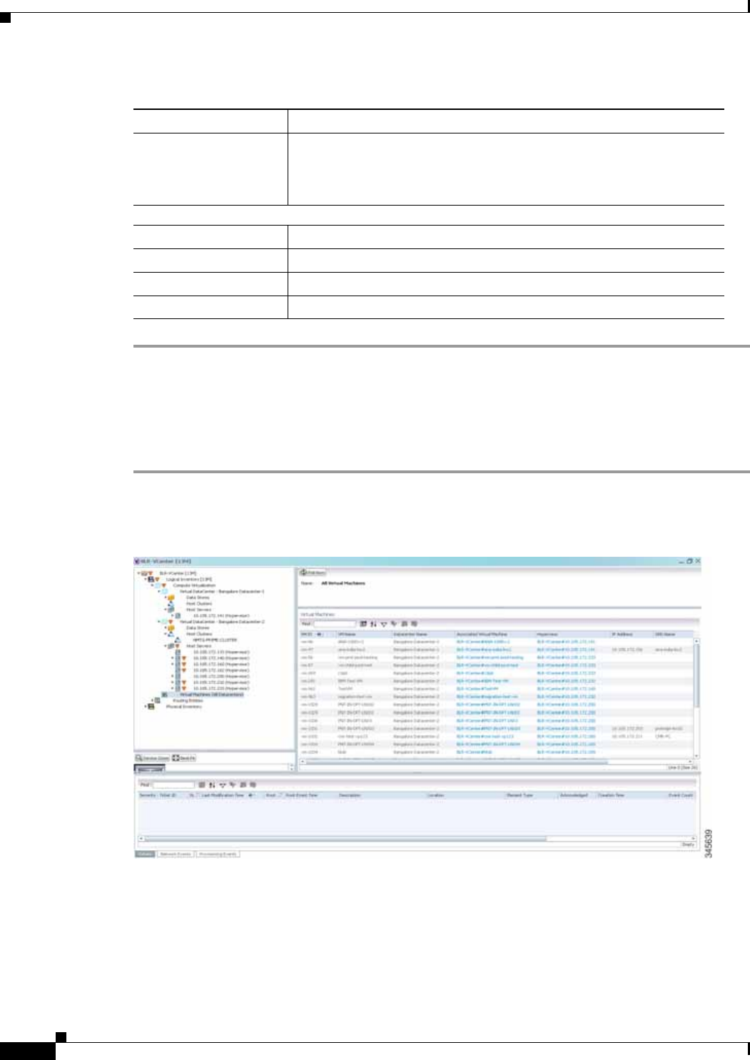
26-18
Cisco Prime Network 4.0 User Guide OL-29343-01
Chapter 26 Monitoring Data Center Configurations
Virtualization
Viewing all the Virtual Machines managed by vCenter
To view a list of all the virtual machines managed by a data center:
Step 1 Right-click on the required device and choose the Inventory option.
Step 2 In the Inventory window, choose Logical Inventory > Compute Virtualization > Data Center > All
Virtual Machines. A list of virtual machines is displayed in the content pane as shown in Figure 26-6.
Table 26-8 describes the virtual machine details available in the list.
Duplex Mode Communication mode, which could be one of the following:
• Half—Transmit data in one direction at a time.
• Full—Transmit data in both the directions at the same time.
Compute Resource Pool
Provider Name The compute resource pool name.
Description The description of the compute resource pool.
Status The status of the compute resource pool.
Root Pool Indicates whether the compute resource pool is the root pool.
Table 26-7 Host Servers of a Data Center (continued)
Field Name Description

26-19
Cisco Prime Network 4.0 User Guide
OL-29343-01
Chapter 26 Monitoring Data Center Configurations Virtualization
Viewing the Virtual Machines of a Data Center
To view the virtual machines for a data center:
Step 1 Right-click on the required device and choose the Inventory option.
Step 2 In the Inventory window, choose Logical Inventory > Compute Virtualization > Data Center > All
Host > Virtual Machine. A list of virtual machines is displayed in the content pane.
Step 3 Click the hyperlinked virtual machine name to view more details about the virtual machine.
Prime Network Vision takes you to the virtual machine node under the mapped host server in the logical
inventory. You can view the virtual machine properties on the content pane or by right-clicking the
virtual machine and choosing Properties.
Table 26-9 describes the properties of the virtual machine.
Table 26-8 Virtual Machines
Field Name Description
Name Name of the associated data center.
Virtual Machines
VM ID The unique identification code for the virtual machine.
VM Name The name of the virtual machine.
Data Center Name The name of the data center associated to the virtual machine.
Associated VM Entity The associated virtual machine entity.
Hypervisor The hypervisor associated tot he virtual machine.
DNS Name The DNS name of the virtual machine.
IP Address The IP address of the virtual machine.
MAC Address The MAC address of the virtual machine.

26-20
Cisco Prime Network 4.0 User Guide OL-29343-01
Chapter 26 Monitoring Data Center Configurations
Virtualization
Table 26-9 Virtual Machine Properties
Field Name Description
VM ID The unique identification code of the virtual machine.
Name Name of the virtual machine.
IP Address IP address of the virtual machine.
DNS Name Domain name of the virtual machine.
MAC Address MAC Address of the virtual machine.
State Execution state of the virtual machine, which could be Powered On,
Powered Off, or Suspended.
VM Version Hardware version of the virtual machine.
Virtual CPU Number of virtual CPUs configured for the virtual machine on the host
server.
Minimum Required
EVC Mode Minimum required EvC of the virtual machine.
VM Template The virtual machine template.
Management Address The management address configured for the virtual machine.
Host Name The host name of the virtual machine.
Virtual Data Center
Name The virtual data center name associated to the virtual machine.
Fault Tolerance Enabled Indicates whether fault tolerance service is enabled or not. This service
provides continuous availability by protecting the primary virtual
machine with a secondary virtual machine that runs simultaneously on
a separate host.
Software Type Type of the software used by the virtual machine.
Source Resource Pool The source resource pool associated to the virtual machine.
System Uptime The date and time when the virtual machine was last booted up.
Statistics tab
CPU Usage CPU usage by the virtual machine, in GHz.
Memory Usage Memory usage by the virtual machine, in GB.
Disk Usage Amount of disk space used by the virtual machine, in GB.
Active Guest Memory
Usage Active guest memory used by the virtual machine, in GB.
CPU Allocation tab
Resource Type The type of resource, which in this instance is CPU.
Maximum Allocation Maximum CPU allocation for the virtual machine, in GHz.
Startup Allocation The startup CPU allocation for the virtual machine, in GHz.
Guaranteed Allocation The guaranteed CPU allocation for the virtual machine, in GHz.
Overhead Allocation The overhead CPU allocation for the virtual machine, in GHz.
Unlimited Maximum
Allocation Unlimited maximum allocation capacity availability check for the
virtual machine. Value could be true or false.

26-21
Cisco Prime Network 4.0 User Guide
OL-29343-01
Chapter 26 Monitoring Data Center Configurations Virtualization
Expandable Allocation Expandable allocation availability for the virtual machine. Value could
be true or false.
Share Relative importance of the virtual machine for CPU allocation, which
could be High, Normal, or Low.
Custom Share Weight Custom share weight assigned to the virtual machine.
Memory Allocation tab
Resource Type The type of resource.
Startup Allocation The startup memory allocation for the virtual machine, in GB.
Guaranteed Allocation The guaranteed memory allocation for the virtual machine, in GB.
Maximum Allocation Maximum memory allocation for the virtual machine, in GB.
Overhead Allocation Overhead memory allocation for the virtual machine, in GB.
Unlimited Maximum
Allocation Unlimited maximum allocation capacity availability check for the
virtual machine. Value could be true or false.
Expandable Allocation Expandable allocation availability for the virtual machine. Value could
be true or false.
Share Relative importance of the virtual machine for memory allocation,
which could be High, Normal, or Low.
Custom Share Weight Custom share weight assigned to the virtual machine.
Disk Allocation tab
Resource Type The type of resource, which in this instance is Disk.
Startup Allocation The startup disk allocation for the virtual machine, in GB.
Guaranteed Allocation Guaranteed resource allocation for the virtual machine, in GB.
Maximum Allocation Maximum disk allocation for the virtual machine, in GB.
Overhead Allocation Overhead disk allocation for the virtual machine, in GB.
Unlimited Maximum
Allocation Unlimited maximum allocation capacity availability check for the
virtual machine. Value could be true or false.
Expandable Allocation Expandable allocation availability for the virtual machine. Value could
be true or false.
Share Relative importance of the virtual machine for memory allocation,
which could be High, Normal, or Low.
Custom Share Weight Custom share weight assigned to the virtual machine.
Data Stores tab
Data Stores Name Name of the data store associated with the virtual machine.
Associated Data Sore Click the hyperlink to view the associated data store under the All Data
Stores node.
Virtual Interfaces tab
Name Name of the network endpoint of the virtual entity.
Type Type of the virtual entity network endpoint.
IP Address Primary IP address of the virtual entity network endpoint.
Table 26-9 Virtual Machine Properties (continued)
Field Name Description
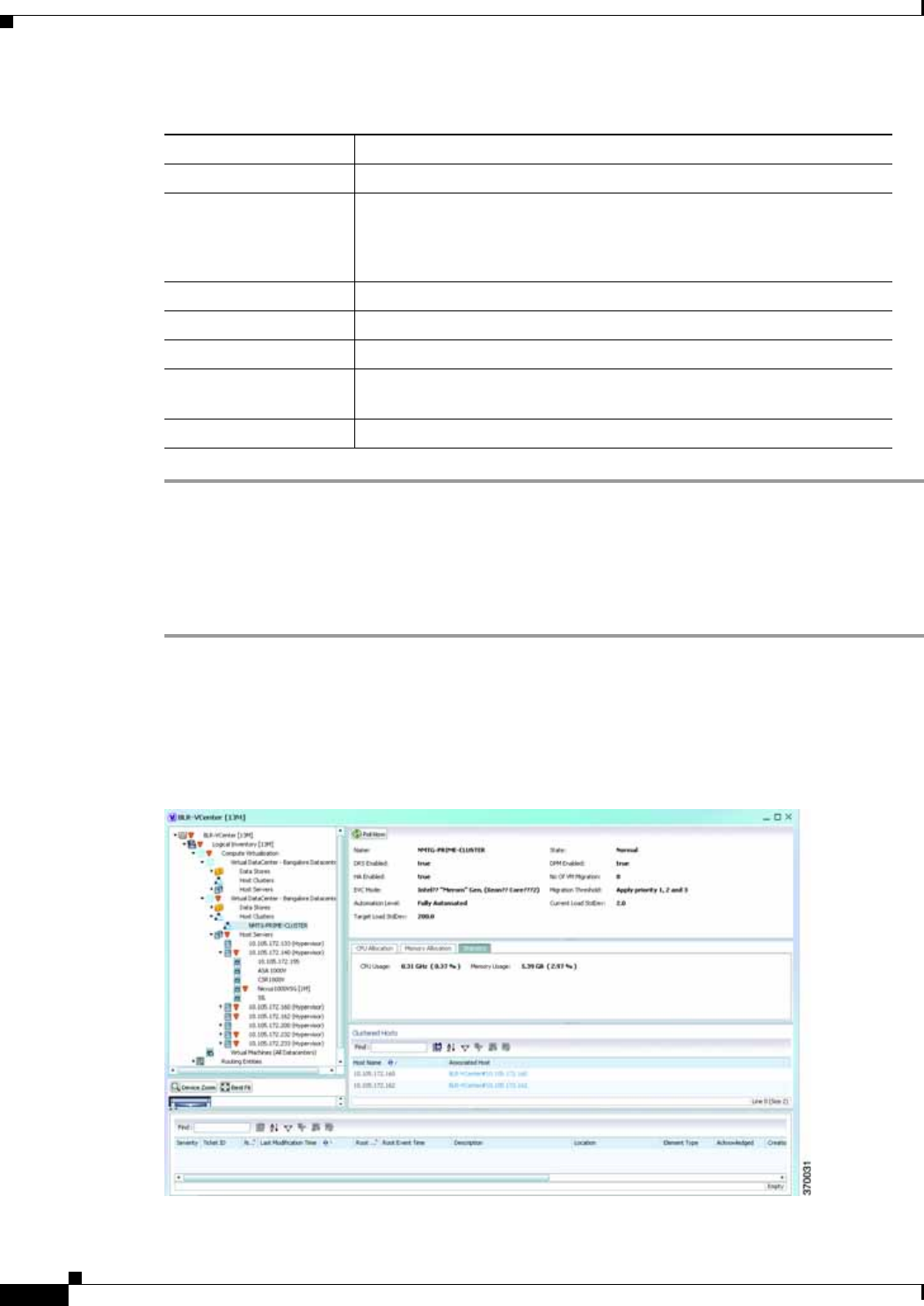
26-22
Cisco Prime Network 4.0 User Guide OL-29343-01
Chapter 26 Monitoring Data Center Configurations
Virtualization
Viewing the Host Cluster Details
To view the host cluster details:
Step 1 In Prime Network Vision, right-click on the required device and select the Inventory option.
Step 2 In the Inventory menu, expand the Logical Inventory node.
Step 3 Select Compute Virtualization > Data Center > Host Clusters > Host cluster. The host cluster details
are displayed in the content pane as shown in Figure 26-7.
Figure 26-7 Host Cluster Details
MAC Address MAC address of the virtual entity network endpoint.
Duplex Mode Communication mode, which could be one of the following:
• Half—Transmit data in one direction at a time.
• Full—Transmit data in both the directions at the same time.
Operational Status The operational status of the virtual machine.
Administrative Status The administrative status of the virtual machine.
Speed The speed of the processor in the virtual machine.
MTU The maximum number of transmission units (in bytes) for the virtual
machine.
Secondary Address The secondary IP address of the virtual machine.
Table 26-9 Virtual Machine Properties (continued)
Field Name Description

26-23
Cisco Prime Network 4.0 User Guide
OL-29343-01
Chapter 26 Monitoring Data Center Configurations Virtualization
Table 26-10 describes the Host Cluster details.
Table 26-10 Host Cluster Details
Field Name Description
Name The name of the host cluster.
Data Center Name The name of the associated data center.
Description The description of the host cluster.
State The status of the host cluster, which can be any one of the following:
• Unknown
• Normal
• Warning
• Alert
DRS Enabled Indicates whether the VMware Distributed Resource Scheduler (DRS)
feature is enabled for the host cluster.
DPM Enabled Indicates whether the VMware Distributed Power Management (DPM)
feature is enabled for the host cluster.
HA Enabled Indicates whether the VMware High Availability (HA) feature is
enabled for the host cluster.
No. of VM Migration The number of virtual machines that have been migrated from one server
to another within the same cluster.
EVC Mode The Enhanced vMotion Compatibility (EVC) mode of the host cluster.
Migration Threshold The migration threshold for the host cluster.
Automation Level Indicates that the placement and migration recommendations run
automatically for the host cluster.
Current Load Std dev The current host load standard deviation for the host cluster.
Target Load Std dev The target hot load standard deviation for the host cluster.
CPU Allocation
Allocatable The maximum CPU allocation for the virtual machine, in GHz.
Reserved The CPU allocation reserved for the virtual machine, in GHz.
Unreserved The unreserved CPU allocation for the virtual machine, in GHz.
Unlimited Provision Indicates whether the unlimited CPU provision is available for the
virtual machine.
Share Relative importance of the virtual machine for CPU allocation, which
could be High, Normal, or Low.
Custom Share Weight The custom share weight assigned to the virtual machine.
Memory Allocation
Allocatable The maximum memory allocation for the virtual machine, in GB.
Reserved The memory allocation reserved for the virtual machine, in GB.
Unreserved The unreserved memory allocation for the virtual machine, in GB.
Unlimited Provision Indicates whether unlimited memory allocation provision is available
for the virtual machine.

26-24
Cisco Prime Network 4.0 User Guide OL-29343-01
Chapter 26 Monitoring Data Center Configurations
Virtualization
Viewing the Resource Pool Details
To view the resource pool details:
Step 1 In Prime Network Vision, right-click on the required device and select the Inventory option.
Step 2 In the Inventory menu, expand the Logical Inventory node.
Step 3 Select Compute Virtualization > Data Center > Host Clusters > Host cluster. The host cluster details
are displayed in the content pane.
Note Alternatively, you can also view the host cluster details by selecting Compute Virtualization > Data
Center > All Host > Host.
Step 4 In the Compute Resource Pools tab in the content pane, click on a resource pool link in the Resource
Pool field. The Compute Resource Pool Properties window is displayed.In
Table 26-12 describes the resource pool details.
Share The relative importance of the virtual machine for memory allocation,
which could be High, Normal, or Low.
Custom Share Weight The custom share weight assigned to the virtual machine.
Statistics tab
CPU Usage CPU usage by the virtual machine, in GHz.
Memory Usage Memory usage by the virtual machine, in GB.
Disk Usage Amount of disk space used by the virtual machine, in GB.
Active Guest Memory
Usage Active guest memory used by the virtual machine, in GB.
Clustered Hosts
Host Name The name of the host server in the clustered host.
Associated Host The link to the associated host, which when clicked will take you to the
relevant host server.
Compute Resource Pool
Provider Name The compute resource pool name.
Description The description of the compute resource pool.
Status The status of the compute resource pool.
Root Pool Indicates whether the compute resource pool is the root pool.
Table 26-10 Host Cluster Details (continued)
Field Name Description

26-25
Cisco Prime Network 4.0 User Guide
OL-29343-01
Chapter 26 Monitoring Data Center Configurations Virtualization
Table 26-11 Resource Pool Properties
Field Name Description
Name The compute resource pool name.
Provider Name The description of the compute resource pool.
Status The status of the compute resource pool.
Root Pool Indicates whether the compute resource pool is the root pool.
CPU Allocation tab
Resource Type The type of resource, which in this instance is CPU.
Allocatable The maximum CPU allocation for the virtual machine, in GHz.
Reserved The CPU allocation reserved for the virtual machine, in GHz.
Unreserved The unreserved CPU allocation for the virtual machine, in GB.
Unlimited Provision Indicates whether unlimited CPU allocation provision is available for
the virtual machine.
Share The relative importance of the virtual machine for CPU allocation,
which could be High, Normal, or Low.
Configured Reservation The CPU reservation configured for the virtual machine.
Available Reservation The CPU reservation available for the virtual machine.
Overhead The overhead CPU allocation for the virtual machine, in GHz.
Custom Share Weight The custom share weight assigned to the virtual machine.
Memory Allocation tab
Resource Type The type of resource.
Allocatable The maximum memory allocation for the virtual machine, in GHz.
Reserved The memory allocation reserved for the virtual machine, in GHz.
Unallocated The memory not allocated for the virtual machine.
Overhead The overhead memory allocation for the host center, in GHz.
Unlimited Provision Indicates whether unlimited memory allocation provision is available
for the virtual machine.
Unreserved The unreserved memory allocation for the virtual machine, in GB.
Share The CPU reservation configured for the virtual machine.
Custom Share Weight The CPU reservation available for the virtual machine.
Configured Reservation The memory reservation configured for the virtual machine.
Available Reservation The memory reservation available for the virtual machine.
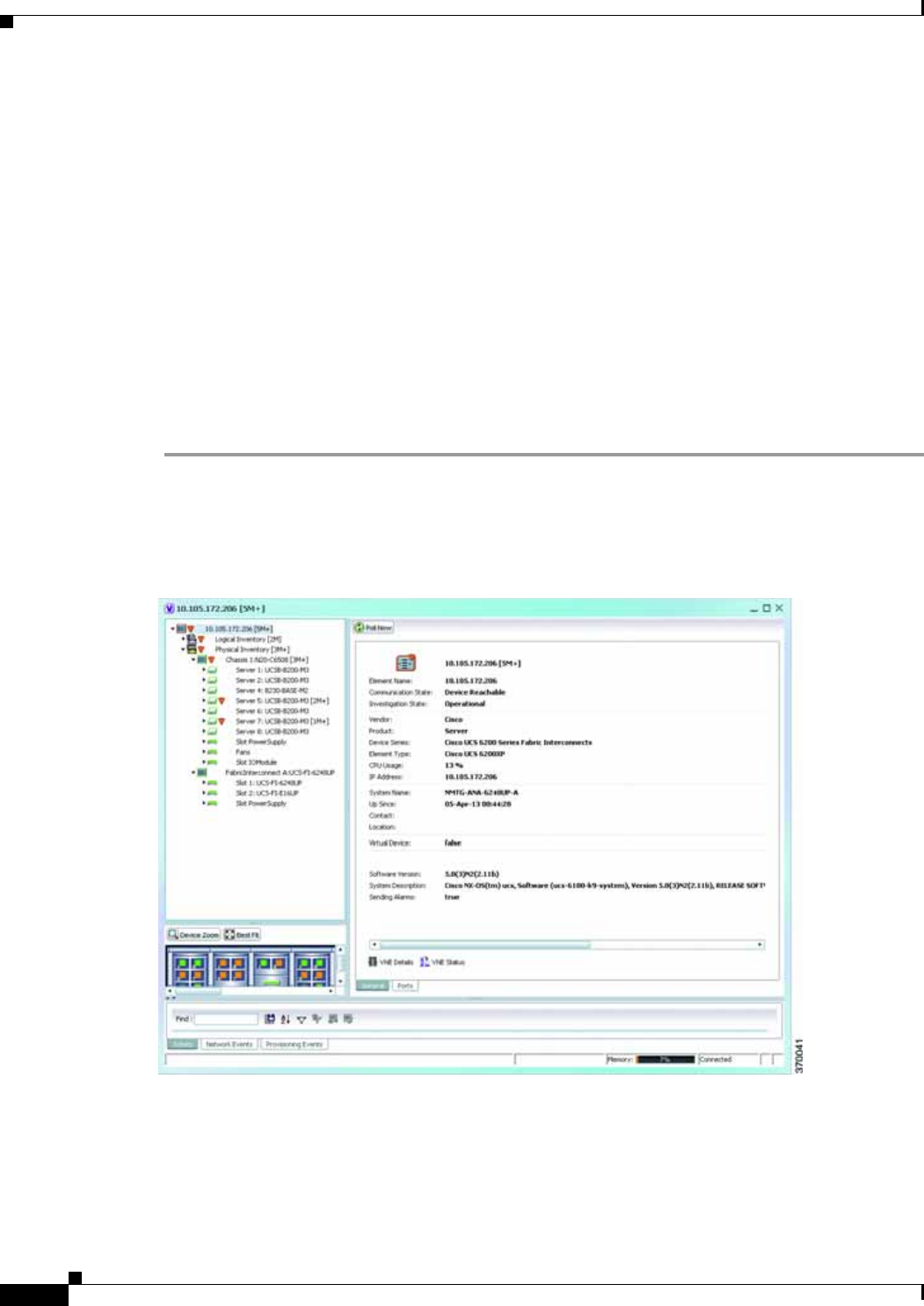
26-26
Cisco Prime Network 4.0 User Guide OL-29343-01
Chapter 26 Monitoring Data Center Configurations
Viewing the Map Node for an UCS Network Element
Viewing the Map Node for an UCS Network Element
Using Prime Network Vision, you can view the physical layout and topology among the multi-chassis
devices on the map. The multi-chassis devices have more than one physical chassis, but they are
represented as a single entity in Prime Network. In a map, this device is shown as an aggregation of all
the device chassis. For more information on viewing multi-chassis devices, see Viewing Multi-Chassis
Devices, page 5-19.
For a Cisco Unified Computing Service (UCS) device, you can view its chassis along with the other
elements relevant to the UCS device, such as Blade Server and IO Modules.
Another important component of the UCS is the Fabric InterConnect. The Fabric InterConnect is a core
part of the UCS device. It provides both network connectivity and management capabilities to all
attached blades and chassis. All chassis, and therefore all blades, attached to the interconnects become
part of a single, highly available management domain.
To view the physical inventory of a UCS:
Step 1 Right-click on the UCS device and choose the Inventory option.
Step 2 In the Inventory window, expand the Physical Inventory node. The Chassis and Fabric Interconnect
chassis are displayed below the node as shown in Figure 26-8.
Figure 26-8 Physical Inventory Node for a UCS Device
Step 3 Expand the Chassis node. The Blade servers, Fans, and the IO Modules that make up the Chassis are
displayed under this node.
Step 4 Expand the Fabric InterConnect node.The slots and the power supply are available here. You can click
on each individual node under these nodes to view more details.

26-27
Cisco Prime Network 4.0 User Guide
OL-29343-01
Chapter 26 Monitoring Data Center Configurations Viewing the Map Node for an UCS Network Element
Step 5 Close the inventory window.
Each of these parts, i.e. the blade servers, Fabric InterConnect chassis, and IO Modules, can be
connected to each other internally. For example, an IO Module can be connected to a blade server or
there could also be a link between the IO Module and Fabric InterConnect chassis.
The Ethernet links between the different components of a UCS can be categorized as:
• Backplane links—The links that connect a chassis to a backplane port via the IO Module.
• Fabric links—The links that connect a chassis to a Fabric InterConnect port via the IO Module.
You can also view this link in a map that contains a separate map node for each of the following elements:
• Fabric Interconnect Chassis
• Blade Server Chassis
• Cisco Blade Server
• IO Module
The blade server chassis is shown as an aggregation that also contains the IO Module.
To view the map for a UCS device:
Step 1 In Cisco Prime Network Vision, open a map with a UCS device. The UCS device is displayed with a
plus (+) sign. Click on the + sign. The map containing the links between each element in the UCS device
is shown in the window as shown in Figure 26-9.
Figure 26-9 UCS Map Node with Aggregation Links

26-28
Cisco Prime Network 4.0 User Guide OL-29343-01
Chapter 26 Monitoring Data Center Configurations
Viewing the Map Node for an UCS Network Element
Note Sub-nodes are available for the chassis that have blade servers under them. You can expand/contract
these sub-nodes to view more details. However, the elements under the Fabric InterConnect chassis will
not be displayed in the map.You can also view the inventory for an element by double-clicking on a node
in the map. The inventory window will open with the selected node.
Step 2 Hover your mouse cursor over the required link in a map. A link tooltip is displayed. The tooltip displays
the link endpoints identified by the element or service name and the number of links represented by the
line on the map.
Step 3 To view additional link information, click the tooltip. The link quick view window is displayed.
Alternatively, you can also double-click the link to view the link quick view window.
Note You can view links belonging to a specific type by clicking the Filter icon in the navigation pane and
selecting the relevant check box. Open the link again and only the selected type of link is displayed. For
more information about filtering a map, see Filtering Links in a Map, page 5-25
Step 4 Close the window.
Step 5 In the map, double-click an element icon to open the Physical inventory and view the ports under it. For
example, if you double-click on an IO Module element, the Inventory window is displayed along with
the Backplane and Fabric ports under the IO Module node.
Step 6 In the map, double click on a link to view it’s properties such as the link type, port alias, and port
location. For more information on link properties, see Viewing Link Properties, page 6-4.
Note The links between the UCS components can also be viewed in the Cisco Unified Computing System
Manager application.
Discovering the UCS Devices by Network Discovery
The Network Discovery feature automatically discovers network devices by traversing the network. The
required information is an IP address for a seed device, and the SNMPv 2 or SNMPv 3 credentials. This
information is added to a discovery profile that specifies the IP and SNMP information, along with any
additional protocols or filters you want Prime Network to use.
You can also discover the UCS devices by Network Discovery. To manage a UCS device, the CLI and
http credentials are required. However, the existing network discovery does not support http.
Since the CLI and http credentials are identical most of the times, the CLI credentials will be copied into
http. You need to create a new discovery profile (using telnet or SSH credentials) for the UCS device and
execute it. For more information about adding devices using Network Discovery, see the Cisco Prime
Network 4.0 Administrator Guide.
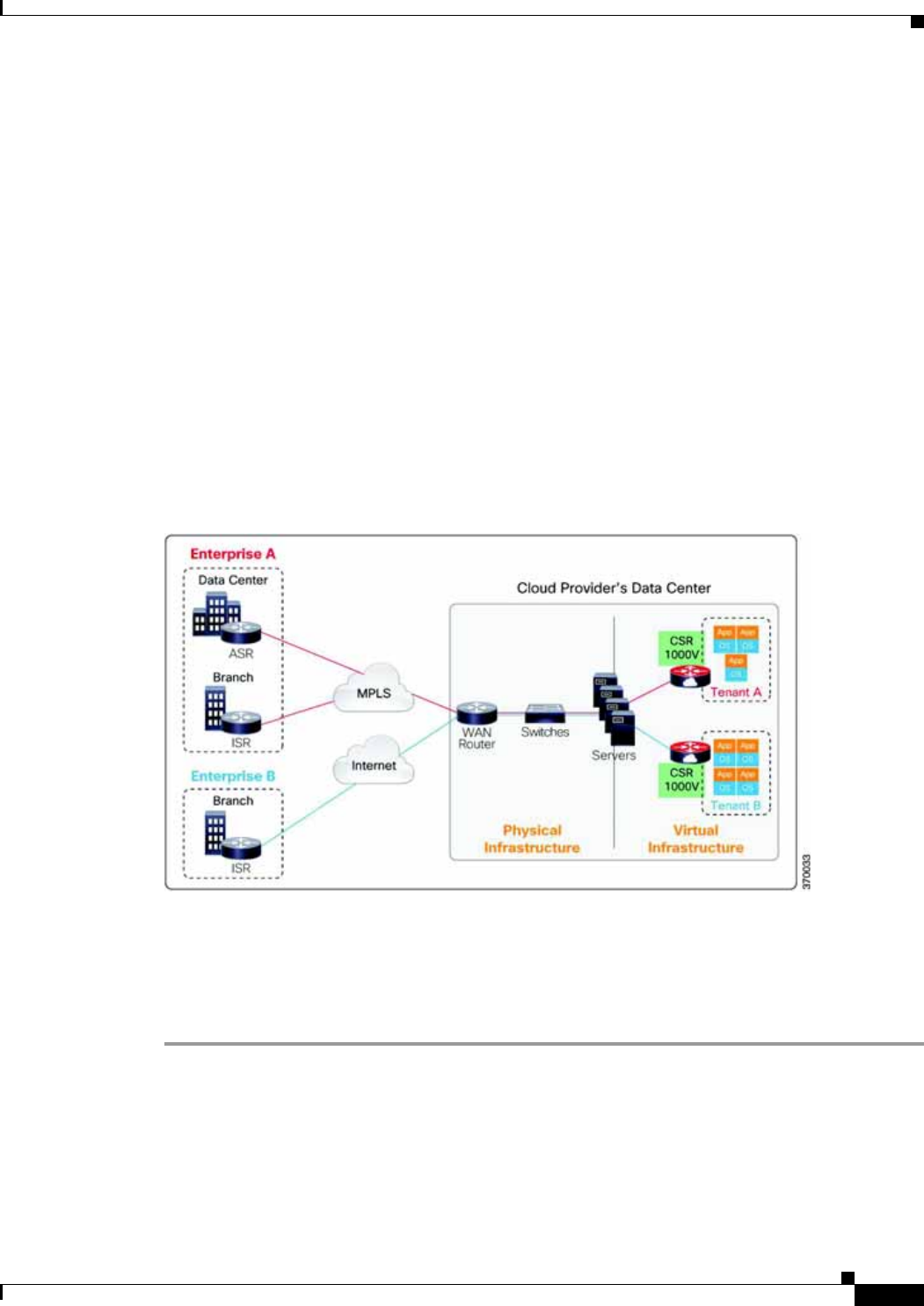
26-29
Cisco Prime Network 4.0 User Guide
OL-29343-01
Chapter 26 Monitoring Data Center Configurations Viewing the Virtual Network Devices of a Data Center
Viewing the Virtual Network Devices of a Data Center
Prime Network supports the following virtual network devices of a data center:
• Cisco Cloud Service Router (CSR) 1000v
• Virtual Security Gateway
Viewing the CSR 1000v Properties
The Cisco Cloud Services Router (CSR) 1000V is a single-tenant router in virtual form-factor that
delivers comprehensive WAN gateway functionality to multi-tenant provider-hosted clouds. It is a
software router that an enterprise or a cloud provider can deploy as a virtual machine (VM) in a
provider-hosted cloud.The Cisco CSR 1000V provides selected Cisco IOS XE features on a
virtualization platform. It also provides secure connectivity from the enterprise premise (such as a
branch office or data center) to the public or private cloud. Figure 26-10 depicts the deployment of CSR
1000v on a provider hosted cloud:
Figure 26-10 Deployment of CSR 1000v on a Provider Hosted Cloud
The Cisco CSR 1000V serves primarily as a router per tenant. In other words, since the CSR 1000v is
situated on the tenant’s side, each tenant gets its dedicated routing instance and services (along with its
own VPN connections, firewall policies, QoS rules, access control, and so on).
To view the CSR 1000v properties:
Step 1 In Prime Network Vision, open a map that contains the CSR 1000v device.
Step 2 Right-click and choose the Inventory option to open the Inventory window.
Step 3 In the Inventory window, click the device name to view the Element properties as shown in
Figure 26-11. For more information about the properties window, see Viewing the Properties of a
Network Element, page 3-6.
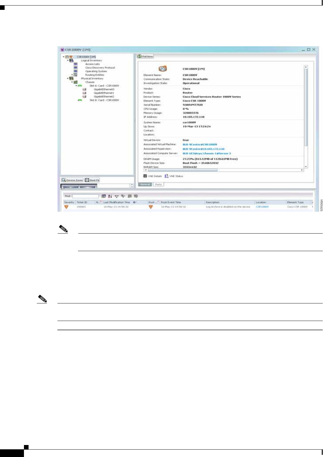
26-30
Cisco Prime Network 4.0 User Guide OL-29343-01
Chapter 26 Monitoring Data Center Configurations
Viewing the Virtual Network Devices of a Data Center
Figure 26-11 Element Properties Window
Note The CSR 1000v device is associated with a hypervisor and physically available on a blade server.
The links to the hypervisor and blade server are displayed in the Properties window.
Step 4 Under the Logical Inventory node, you can view the Access Lists, Cisco Discovery Protocol, Operating
System requirements, and Routing Entities. For more information about the logical inventory properties,
see Viewing the Logical Properties of a Network Element, page 3-27.
Step 5 Under the Physical Inventory node, you can view the two slots under the Chassis node.
Note The first slot contains the Route Processor with three interface ports—one for management and the other
two for data traffic. The second slot contains the Embedded Services Processor.
Viewing the VSG Properties
The Cisco Virtual Security Gateway (VSG) is a virtual firewall appliance that provides trusted access to
virtual data center and cloud environments. The Cisco VSG enables a broad set of multi tenant
workloads that have varied security profiles to share a common compute infrastructure in a virtual data
center private cloud or in a public cloud. By associating one or more virtual machines (VMs) into distinct
trust zones, the Cisco VSG ensures that access to trust zones is controlled and monitored through
established security policies.
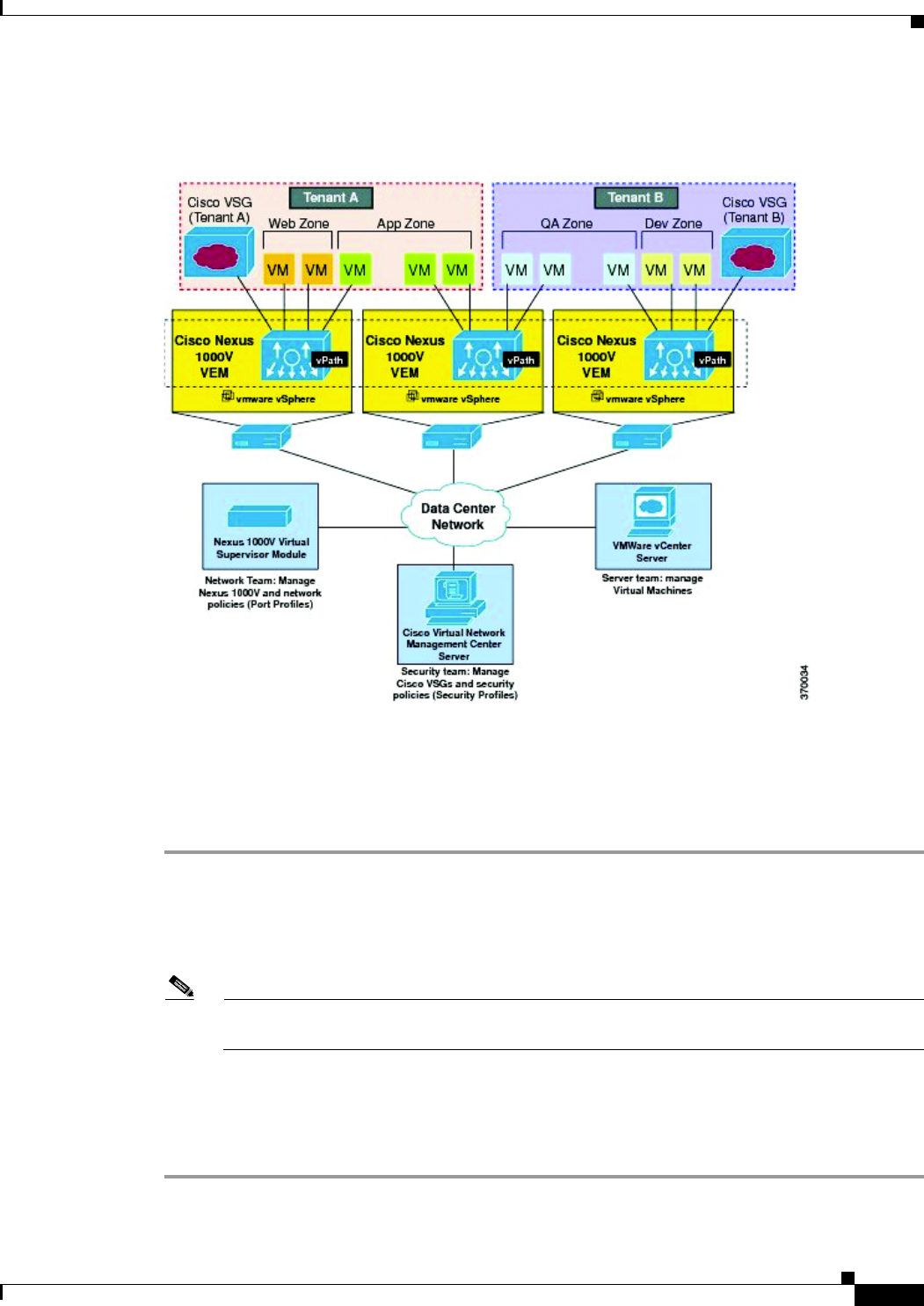
26-31
Cisco Prime Network 4.0 User Guide
OL-29343-01
Chapter 26 Monitoring Data Center Configurations Viewing the Virtual Network Devices of a Data Center
Figure 26-12 depicts the deployment of VSG:
Figure 26-12 Deployment of VSG
The Cisco VSG operates with the Cisco Nexus 1000V in the VMware vSphere hypervisor, and the Cisco
VSG leverages the virtual network service datapath (vPath) that is embedded in the Nexus 1000V Virtual
Ethernet Module (VEM). A VEM can be associated to a Cisco VSG.
To view the VSG Properties:
Step 1 In Prime Network Vision, open a map that contains the VSG device.
Step 2 Right-click and choose the Inventory option to open the Inventory window.
Step 3 In the Inventory window, click the device name to view the Element properties. For more information
about the properties window, see Viewing the Properties of a Network Element, page 3-6.
Note The VSG device is associated with a hypervisor and physically available on a blade server. The
links to the hypervisor and blade server are displayed in the Properties window.
Step 4 Under the Logical Inventory node, you can view the Access Lists, Cisco Discovery Protocol, Operating
System requirements, and Routing Entities. For more information about the logical inventory properties,
see Viewing the Logical Properties of a Network Element, page 3-27.
Step 5 Under the Physical Inventory node, you can view only one slot.

26-32
Cisco Prime Network 4.0 User Guide OL-29343-01
Chapter 26 Monitoring Data Center Configurations
Viewing the Compute Server Support Details
Viewing the Compute Server Support Details
Prime Network provides support for the following compute servers:
• UCS B-Series Servers—The Cisco UCS B-Series Blade Servers are crucial building blocks of the
Cisco Unified Computing System and are designed to increase performance, energy efficiency, and
flexibility for demanding virtualized and non virtualized applications. Each Cisco UCS B-Series
Blade Server uses converged network adapters (CNAs) for access to the unified fabric. This design
reduces the number of adapters, cables, and access-layer switches while still allowing traditional
LAN and SAN connectivity.
• UCS C-Series Servers—Cisco UCS C-Series Rack Servers deliver unified computing in an
industry-standard form factor to reduce total cost of ownership and increase agility
• Third party or Non-Cisco servers—Includes support for non-UCS servers such as HP, Dell or IBM.
In Prime Network, the UCS B-Series and UCS C-Series servers are modelled as part of the UCS VNE.
The UCS C-Series (standalone) and non-Cisco servers are modelled as individual VNEs.
Note For a Cisco UCS device, you can also view the physical inventory, which includes the blade server,
Fabric InterConnect and IO Modules. You can also view the physical layout and topology for the UCS
device on the map. For more information, see Viewing the Map Node for an UCS Network Element,
page 26-26.
Note There is also a direct correlation between the blade server and its associated virtual entities. For instance,
if the blade server is shut down, then the associated entities such as the virtual machines and hypervisor
will also be shut down.
To view the UCS server details:
Step 1 In Prime Network Vision, right-click a UCS device and choose the Inventory option.
Step 2 In the Inventory window, expand the Physical Inventory node.
Step 3 Select Chassis > Blade Server. The blade server configuration details are displayed in the content pane
as shown in Figure 26-13.
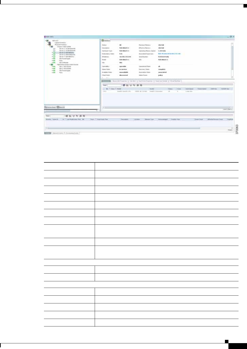
26-33
Cisco Prime Network 4.0 User Guide
OL-29343-01
Chapter 26 Monitoring Data Center Configurations Viewing the Compute Server Support Details
Figure 26-13 Blade Server Configuration Details
Table 26-12 describes the configuration details of a blade server.
Table 26-12 Blade Server Configuration Details
Field Name Description
Name The name of the blade server.
Uuid The unique ID of the blade server.
Status The status of the server.
Maximum Memory The total amount of memory (in gigabytes) available on the server.
Description The description of the server.
Effective Memory The amount of memory (in gigabytes) currently available to the server.
IP Address The IP address of the blade server.
Operating Memory
Speed The speed (in GHz) at which the operating memory can be accessed.
Redundancy State The redundancy state of the server, which can be Online or Offline.
Associated Hypervisor The hypervisor associated to the blade server. Click this link to view the
hypervisor details.
Sub Slots tab
Equipment The name of the equipment.
Type The type of equipment.
Processors tab
Name The name of the processor used by the blade server.
Description The description of the processor used by the blade server.
Model The processor model used by the blade server.
Vendor The vendor of the processor.
Status The status of the processor.

26-34
Cisco Prime Network 4.0 User Guide OL-29343-01
Chapter 26 Monitoring Data Center Configurations
Viewing the Compute Server Support Details
Cores The number of cores used by the blade server.
Used Speed The actual used speed of the processor, in GHz.
Rated Speed The rated speed of the processor, in GHz.
RAM Size The RAM size of the processor, in GB.
NvRAM Size The NvRAM Size of the processor, in GB.
Memory Slot Properties tab
Slot Name The name of the memory slot.
Speed The memory slot speed, in GHz.
Memory Capacity The maximum memory capacity of the hard drive, in GB.
Serial Number The serial number of the memory slot.
Status The status of the memory slot.
Hard Drive Properties
Model Name The model name of the hard drive.
Storage Capacity The total storage capacity of the hard drive, in GB.
Free Space The total space available for usage in the hard drive.
isFRU Indicates whether the hard drive is removable.
Drive Type The type of hard drive, which can be any one of the following:
• Fixed Disk
• RAM Disk
• Flash Memory
• Network Disk
• Removable Disk
Status The status of the hard drive.
Hypervisor tab
Fault Tolerance Version The fault tolerance version of the hypervisor.
Uuid The unique ID of the hypervisor.
Model The model of the hypervisor.
EvcMode The Enhanced vMotion Capability (Evc) mode of the hypervisor.
Virtual Data Center
Name The name of the virtual data center of the hypervisor.
Isv Motion Enabled Indicates whether the Lsv motion is enabled.
MAC Address The MAC address of the hypervisor.
Fault Tolerance Enabled Indicates whether fault tolerance service is enabled or not. This service
provides continuous availability by protecting the primary virtual
machine with a secondary virtual machine that runs simultaneously on
a separate host.
Software Type The type of software used by the hypervisor.
Table 26-12 Blade Server Configuration Details (continued)
Field Name Description

26-35
Cisco Prime Network 4.0 User Guide
OL-29343-01
Chapter 26 Monitoring Data Center Configurations Viewing the Compute Server Support Details
Note The Hypervisor and Virtual Machine tabs will be displayed only if the compute server is managed by a
VMware VCenter, which is monitored by the same instance of Prime Network.
Viewing the Non Cisco Server Details
In Prime Network, non Cisco servers such as IBM, HP, and Dell are modelled as individual VNEs. These
servers are modelled based on the operating system installed on them, and not on the native hardware or
management applications running on these hardware.
The following operating systems are supported for modelling:
• Windows
• Linux
• VMWareESXi
• Any other operating system that supports MIB2, RFC-1213-MIB, HOST-RESOURCE-MIB
To view the non Cisco server details:
Step 1 In Prime Network Vision, right-click Non-Cisco device and choose the Inventory option.
Step 2 In the Inventory window, expand the Physical Inventory node.
IP Address The IP address of the hypervisor.
Name The name of the hypervisor.
State The status of the hypervisor, which could be Running, Runnable,
Waiting, Exiting, or Other.
Vendor The name of the vendor for the hypervisor.
Virtual Machines tab
Virtual Machine The name of the virtual machine associated with the blade server. The
severity of the blade server is also displayed along with the name.
IP Address The IP address of the virtual machine.
DNS Name The domain name of the virtual machine.
MAC Address The MAC address of the virtual machine.
State The status of the virtual machine, which could be Powered On, Powered
Off, or Suspended.
VM Version The hardware version of the virtual machine.
Virtual CPU The number of virtual CPUs configured for the virtual machine on the
virtual machine.
Fault Tolerance Enabled Indicates whether fault tolerance service is enabled or not.
Table 26-12 Blade Server Configuration Details (continued)
Field Name Description
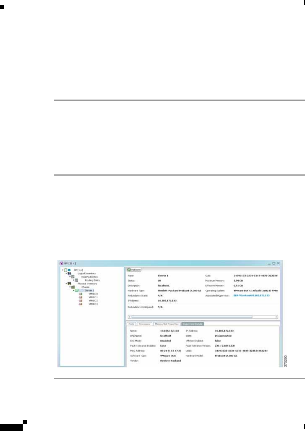
26-36
Cisco Prime Network 4.0 User Guide OL-29343-01
Chapter 26 Monitoring Data Center Configurations
Viewing the Compute Server Support Details
Step 3 Select the Server node. The server configuration details are displayed in the content pane along with the
details of the operating system available in the server. The following tabs are also available:
–
Ports
–
Processors
–
Hard Drive Properties
–
Memory Slot Properties
–
Hypervisor Details
Viewing the Mapping between the Compute Server and Hypervisor
The Cisco and non Cisco servers also support hypervisory functions to support various operating
systems. Prime Network allows you to view the mapping details between the compute server and the
hypervisor.
To view the mapping between the compute server and hypervisor:
Step 1 In Prime Network Vision, right-click a UCS device and choose the Inventory option.
Step 2 In the Inventory window, expand the Physical Inventory node.
Step 3 Select Chassis > Blade Server. The blade server configuration details are displayed in the content pane.
Step 4 Click the link in the Associated Hypervisor field to go to the relevant hypervisor under the vCenter
node. The details of the hypervisor are displayed in the content pane, which also includes the Associated
Compute Server field that contains a link to the relevant compute server.
Each blade server under the Chassis in the Physical inventory will link to the associated hypervisor. This
is also applicable to the third party servers as shown in . In other words, the third party server also
contains a link to the associated hypervisor.

26-37
Cisco Prime Network 4.0 User Guide
OL-29343-01
Chapter 26 Monitoring Data Center Configurations Viewing the Storage Area Network Support Details
Viewing the Storage Area Network Support Details
A storage area network (SAN) is a dedicated network that provides access to consolidated, block level
data storage. SANs are primarily used to make storage devices, such as disk arrays, tape libraries, and
optical jukeboxes, accessible to servers so that the devices appear like locally attached devices to the
operating system. A SAN typically has its own network of storage devices that are generally not
accessible through the local area network by other devices.
A virtual storage area network (VSAN) is a collection of ports from a set of connected Fibre Channel
switches, that form a virtual fabric. Ports within a single switch can be partitioned into multiple VSANs,
despite sharing hardware resources. Conversely, multiple switches can join a number of ports to form a
single VSAN.
Most storage networks use the SCSI protocol for communication between servers and disk drive devices.
A mapping layer to other protocols is used to form a network.
In Prime Network, the following technologies are used for storage area networks:
• Fibre Channel (FC)—Fibre Channel is a high-speed network technology (commonly running at 2-,
4-, 8- and 16-gigabit speeds) primarily used for storage networking. It was primarily used in the
supercomputer field, but has now become the standard connection type for storage area networks
(SAN) in enterprise storage. Fibre Channel can help with design of large-scale, storage-intensive
systems. It can also provide a solution that allows rapid storage and retrieval of information, while
simplifying the interconnection of different components in the system
• Fibre Channel over Ethernet (FCoE)—Fibre Channel over Ethernet is an encapsulation of Fibre
Channel frames over Ethernet networks. This allows Fibre Channel to use 10 Gigabit Ethernet
networks (or higher speeds) while preserving the Fibre Channel protocol. It drastically reduces the
number of I/O adapters, cables, and switches in the data center, while providing a wire-once, agile
infrastructure. Based on lossless, reliable 10 Gigabit Ethernet, FCoE networks combine LAN and
multiple storage protocols on a single converged network.
These technologies are supported in the following devices:
• Nexus 5000
• Nexus 7000
• MDS
• UCS
Note The Cisco Fabric InterConnect UCS devices only supports the Fibre Channel over Ethernet technology.
Viewing the Storage Area Network Configuration Details
To view the VSAN configuration details:
Step 1 In Prime Network Vision, right-click the required device and choose the Inventory option.
Step 2 In the Inventory window, expand the Logical Inventory node.
Step 3 Select VSANs > VSAN service. The VSAN configuration details are displayed in the content pane as
shown in the Figure 26-14.
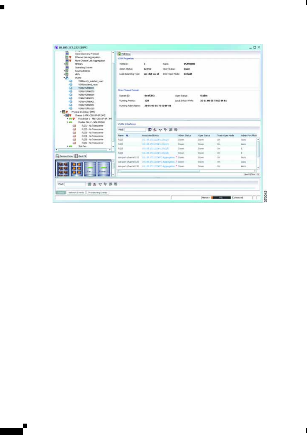

26-39
Cisco Prime Network 4.0 User Guide
OL-29343-01
Chapter 26 Monitoring Data Center Configurations Viewing the Storage Area Network Support Details
Table 26-13 VSAN Configuration Details
Field Name Description
VSAN ID The unique identification code of the VSAN.
Name The name of the VSAN.
Admin Status The administrative status of the VSAN, which can be any one of the
following:
• Active—Indicates that the VSAN is configured and enabled and that
you can activate the services of the VSAN.
• Suspended—Indicates that the VSAN is configured, but not
enabled. Any port configured in this VSAN will also be disabled.
Oper Status The operational status of the VSAN, which can be any one of the
following:
• Up
• Down
Load Balancing Type The method used for load balancing path selection in the VSAN, which
can be any one of the following:
• Source destination ID
• Originator Exchange OX ID
Inter Oper Mode The inter operations mode.
Associated VLAN The name of the VLAN associated to the VSAN.
In Order Delivery The in order delivery of the VSAN.
MTU The maximum number of transmission units (in bytes) of the VSAN.
Fibre Channel Domain
Domain ID The domain ID of the Fibre Channel domain.
Oper Status The operational status of the Fibre Channel domain, which can be any
one of the following:
• Stable
• Enable
• Disable
Running Priority The assigned priority of the switch. This field defaults to 128.
Local Switch WWN The local switch World Wide Name (WWN) for the Fibre Channel,
which is a unique identifier in the SAN.
Running Fabric Name The WWN number of the Fabric to which the switch belongs.
VSAN Interfaces
Name The name of the VSAN technology interface.
Associated Entity The associated Fibre Channel interface, which when clicked will take
you to the relevant Fibre channel node under the Chassis node.

26-40
Cisco Prime Network 4.0 User Guide OL-29343-01
Chapter 26 Monitoring Data Center Configurations
Viewing the Storage Area Network Support Details
Admin Status The administrative status of the interface, which can be any one of the
following:
• Up
• Down
Oper Status The operational status of the interface, which can be any one of the
following:
• Up
• Down
• Trunking
Trunk Oper Mode The operational status of the trunk mode for a VSAN interface, which
can be any one of the following:
• On
• Off
• Auto
Trunk Admin Mode The status of the trunk administrative mode.
Admin Port Mode The administrative port mode of the interface, which can be any one of
the following:
• E—Expansion port, where the interface functions as a fabric
expansion port. This port may be connected to another E port to
create an Inter-Switch Link (ISL) between two switches.
• F—Fabric port, where an interface functions as a fabric port. This
port may be connected to a peripheral device (host or disk)
operating as an N port.
• NP—When the switch is operating in NPV mode, the interfaces that
connect the switch to the core network switch are configured as NP
ports.
• TE—Trunking E port, where the interface functions as a trunking
expansion port. It may be connected to another TE port to create an
extended ISL (EISL) between two switches.
• TF—Trunking fabric port, where an F port with trunk mode enabled
becomes operational.
• TNP—Trunking NP port, where an NP port with trunk mode
enabled becomes operational.
• SD—SPAN Destination port, where the interface functions as a
switched port analyzer.
• FX—An interface configured as FX port can operate in either F port
or FL port mode.
• Auto—An interface configured in auto mode can operate in F port,
E port, or TE port, which is determined during interface
initialization.
Table 26-13 VSAN Configuration Details (continued)
Field Name Description

26-41
Cisco Prime Network 4.0 User Guide
OL-29343-01
Chapter 26 Monitoring Data Center Configurations Viewing the Storage Area Network Support Details
Note For more information about the alarms relating to FC and FCoE, see the Cisco Prime Network 4.0
Supported Service Alarms.
Viewing the FC Interface Details
To view the FC Interface details:
Step 1 In Prime Network Vision, right-click the required device and choose the Inventory option.
Step 2 In the Inventory window, expand the Physical Inventory node.
Step 3 Select Chassis > Module Slot > Fibre channel interface. The FC interface details are displayed in the
content pane.
Table 26-14 describes the FC configuration details.
Oper Port Mode The operational port mode of the port.
Allowed VSANs The VSANs that are active and allowed to receive data for the specified
VSAN range. The port will allow traffic for the VSANs specified here.
Native VSAN The VSAN ID to which the FC port belongs.
Virtual Interface The VFC ID, which is displayed only if the VFC is configured to a port
and the port is bound to a VF.
Fibre Channel The fibre channel associated to the VSAN.
FCS Database Entries tab
Local Interface Name The name of the local interface for VSAN.
Local Connected
Interface The local interface connected to the VSAN.
Local Port The name of the local port for the VSAN.
Remote Port The name of the remote port for the VSAN.
Remote Node The remote node for the VSAN.
Remote Permanent Port The name of the remote permanent port.
Remote Node IP
Address The IP address of the remote node.
Remote Port Name The name of the remote port.
Table 26-13 VSAN Configuration Details (continued)
Field Name Description

26-42
Cisco Prime Network 4.0 User Guide OL-29343-01
Chapter 26 Monitoring Data Center Configurations
Viewing the Storage Area Network Support Details
Table 26-14 FC Configuration Details
Field Name Description
Location Information
Type The type of fibre interface, which can be any one of the following:
• Fibre Channel
Location The location of the FC/FCoE interface.
Sending Alarms Indicates whether the port is sending all alarms correctly.
Port Alias The port alias of the interface.
Managed The managed status.
Status The status of the FC/FCoE interface.
Pluggable Transceiver
Connector Type The type of connector used for the interface.
Pluggable Port State The status of the pluggable port in the interface.
VSAN Interface
Name The name of the VSAN technology interface.
Admin Status The administrative status of the interface, which can be any one of the
following:
• Up
• Down
Oper Status The operational status of the interface, which can be any one of the
following:
• Up
• Down
• Trunking
Trunk Oper Mode The operational status of the trunk mode for a VSAN interface, which
can be any one of the following:
• On
• Off
• Auto
Admin Port Mode The administrative port mode of the interface.
Native VSAN The VSAN ID to which the FC port belongs.
Fibre Channel
Name The name of the fibre channel.
TxB2B Credit The Transmit Buffer to Buffer Credit value for the fibre channel.
Note Buffer to Buffer credit is a flow control mechanism that ensure
that fibre channel switches do not run out of buffers so that the
switches do not drop frames.

26-43
Cisco Prime Network 4.0 User Guide
OL-29343-01
Chapter 26 Monitoring Data Center Configurations Viewing the Storage Area Network Support Details
Viewing the FCoE Interface Details
To view the FCoE Interface details:
Step 1 In Prime Network Vision, right-click the required device and choose the Inventory option.
Step 2 In the Inventory window, expand the Physical Inventory node.
Step 3 Select Chassis > Fixed Slot > FCoE interface. The FCoE interface details are displayed in the content
pane. The following information is displayed in the content pane:
Table 26-15 describes the FCoE configuration details.
RxB2B Credit The Receive Buffer to Buffer Credit value for the fibre channel. This
value is configured for each interface.
Admin Status The administrative status of the fibre channel, which can be any one of
the following:
• Up
• Down
Oper Status The operational status of the fibre channel, which can be any one of the
following:
• Up
• Down
Port WWN The World Wide Name (WWN) of the port for the Fibre Channel.
Table 26-14 FC Configuration Details (continued)
Field Name Description
Table 26-15 FCoE Configuration Details
Field Name Description
VLAN Interface tab
Mode The VLAN interface configuration mode, which can be any one of the
following:
• Unknown
• Access
• Dynamic Auto
• Dynamic Desirable
• Trunk
• Dot 1Q Tunnel
VLAN Type The VLAN interface type, such as Layer 2 VLAN.
Native VLAN ID VLAN Identifier (VID) associated with this VLAN. The range of the
VLAN ID is 1 to 4067.

26-44
Cisco Prime Network 4.0 User Guide OL-29343-01
Chapter 26 Monitoring Data Center Configurations
Viewing the Storage Area Network Support Details
Note For more information about the other sections in this window, see Table 26-14.
Viewing the Fibre Channel Link Aggregation
To view the Fiber Channel Link Aggregation details:
Step 1 In Prime Network Vision, right-click the required device and choose the Inventory option.
Step 2 In the Inventory window, expand the Logical Inventory node.
Step 3 Select the Fibre Channel Link Aggregation option. The list of aggregations are displayed in the content
pane.
Step 4 Double-click on an aggregation. The Fibre Channel Link Aggregation Properties window is displayed
as shown in Figure 26-15.
Allowed VLANs The list of the VLANs allowed on this VLAN interface.
TenGigabit Ethernet
MAC Address The MAC address.
Ethernet LMI Enabled Indicates whether the Ethernet Local Management Interface (LMI) is
enabled.
Discovery Protocols
Discovery Protocol
Type The type of discovery protocol, which can be CDP or LLDP.
Info Displays more information about the protocol type, which can be any
one of the following:
• for CDP—Up or Down
• for LLDP—Tx (Enabled/Disabled) or Rx (Enabled/Disabled)
Ethernet CSMA/CD
Admin Status The administrative status of the Ethernet Carrier sense multiple access
with collision detection (CSMA/CD).
Oper Status The operational status of Ethernet CSMA/CD.
Port Type The type of port.
Last Changed The date and time when the ethernet status was last changed.
Maximum Speed The maximum bandwidth.
Port Description The description of the port as defined by the user.
MTU The size of the Maximum Transmission Unit (MTU) for the interface.
Internal Port Indicates whether an internal port is available.
Table 26-15 FCoE Configuration Details (continued)
Field Name Description
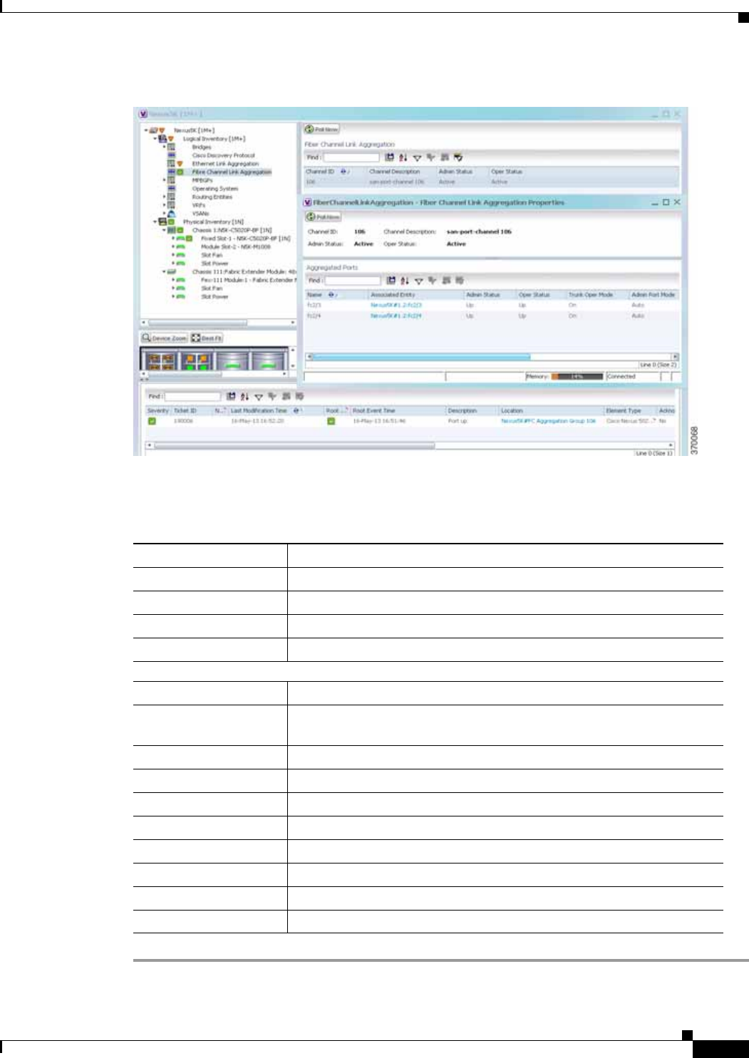
26-45
Cisco Prime Network 4.0 User Guide
OL-29343-01
Chapter 26 Monitoring Data Center Configurations Viewing the Storage Area Network Support Details
Figure 26-15 Fibre Channel Link Aggregation
Table 26-16 describes the Fibre Channel Link Aggregation Properties.
Table 26-16 Fibre Channel Link Aggregation Properties
Field Name Description
Channel ID The unique identification code for the aggregation.
Channel Description The description of the aggregation.
Admin Status The administrative status of the aggregation.
Oper Status The operational status of the aggregation.
Aggregated Ports
Name The name of the port that is included in the aggregation.
Associated Entity The associated port, which when clicked will take you to the relevant FC
or FCoE port.
Admin Status The administrative status of the associated port.
Oper Status The operational status of the associated port.
Trunk Oper Status The Trunk operational status of the associated port.
Admin Port Mode The administrative port mode of the associated port.
Oper Port Mode The operational port mode of the associated port.
Allowed VSANs The number of VSANs that are active and allowed to receive data.
Native VSAN The number of native VSANs.
Virtual Interface The name of the virtual interface for the VSAN.

26-46
Cisco Prime Network 4.0 User Guide OL-29343-01
Chapter 26 Monitoring Data Center Configurations
Searching for Compute Services
Viewing Fibre Channel Links Between Devices in a Map
To view the FC links between devices in a map:
Step 1 In Prime Network Vision, open the map that contains the Fibre Channel links.
Step 2 Click on the Filter icon in the navigation menu and select only the Fibre Channel check box. Click OK.
The map that you have opened only displays the Fibre Channel links between devices. For more
information about viewing these link properties, see Viewing the Map Node for an UCS Network
Element, page 26-26.
Searching for Compute Services
The Compute Services Search feature in Prime Network allows you to search for the following entities:
• Virtual Machines (can be found in the VCenter device)
• Hypervisors (can be found in the VCenter device)
• Bare Metal (For example, the blade servers, which can be found in a UCS device)
To use the Compute services search feature:
Step 1 In Prime Network Vision, select Network Inventory > Compute Services.
Step 2 In the Compute Services window, select the Search radio button.
Step 3 From the Search drop down box, select any one of the following options:
• DNS Name
• IP Address
• Name
Step 4 In the text box available, enter the name based on the option selected in the Search drop-down box.
Step 5 Click Go. The entity details are displayed in the table below as shown in Figure 26-16.

26-47
Cisco Prime Network 4.0 User Guide
OL-29343-01
Chapter 26 Monitoring Data Center Configurations Searching for Compute Services
Figure 26-16 Compute Service Search
Note You can also click the Show All radio button to view a list of devices with hypervisors, blade servers,
and virtual machines.
Table 26-17 describes the compute services search results.
Table 26-17 Compute Services Search Result
Field Name Description
Severity The severity of the device.
Name The name of the device.
Service Type The service type, which can be Virtual Machine, Hypervisor, or Bare
Metal.
IP Address The IP address of the device.
DNS Name The DNS name of the device.
State The status of the device.
Host The host server associated to the device, which when clicked will take
you to the relevant host node.
Compute Server The compute server associated to the device, which when clicked will
take you to the relevant node.
Compute System The device where the blade server is available, which when clicked will
take you to the relevant node.

26-48
Cisco Prime Network 4.0 User Guide OL-29343-01
Chapter 26 Monitoring Data Center Configurations
Searching for Compute Services
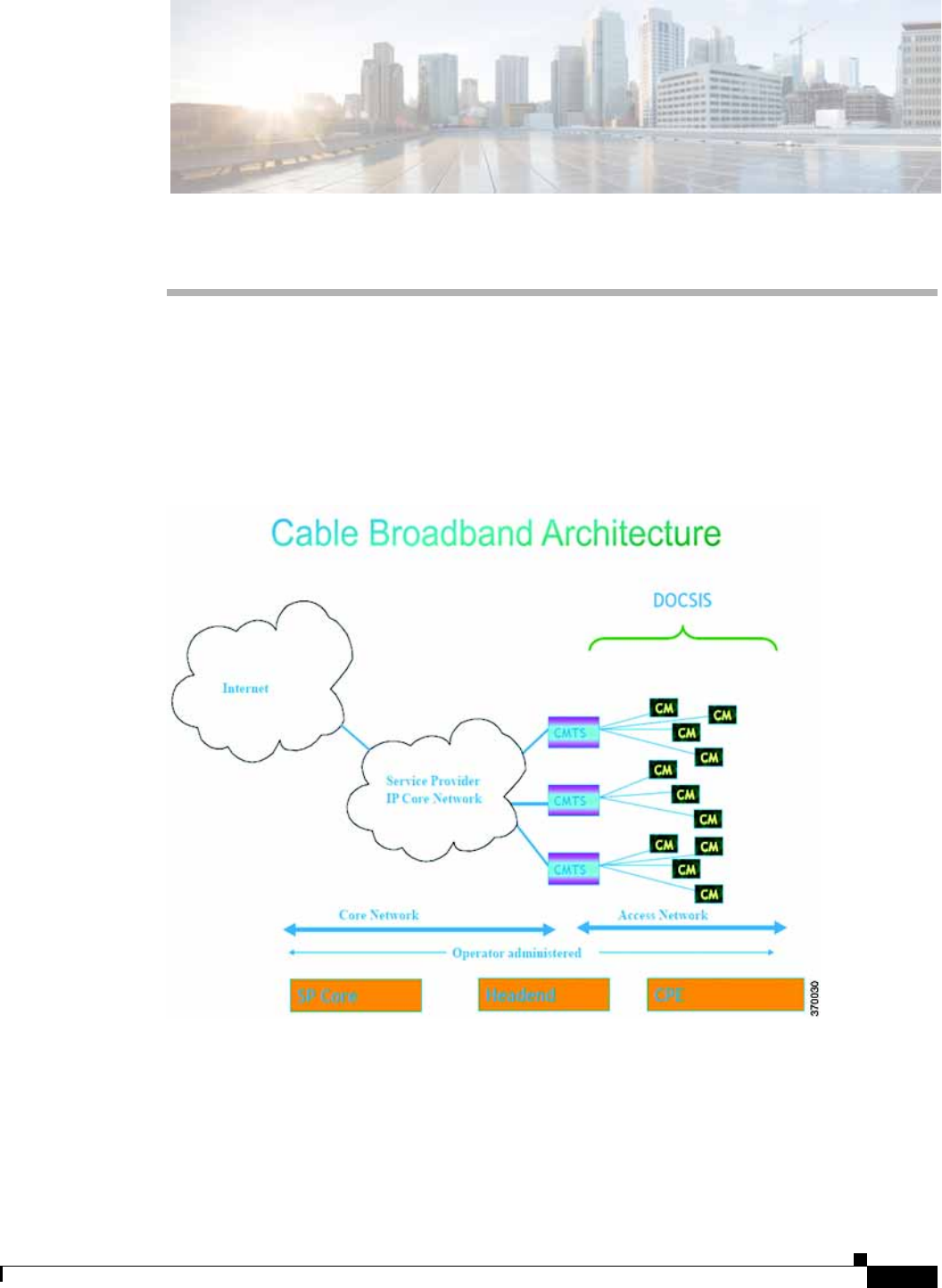
CHAPTER
27-1
Cisco Prime Network 4.0 User Guide
OL-29343-01
27
Monitoring Cable Technologies
Cable broadband communication operates in compliance with the Data Over Cable Service Interface
Specification (DOCSIS) standard which prescribes multivendor interoperability and promotes a retail
model for the consumer's direct purchase of a cable modem (CM) of choice. Figure 27-1 depicts the
architecture of the cable broadband in compliance with this standard:
Figure 27-1 Cable Broadband Architecture
DOCSIS defines two key devices necessary for broadband cable communication:
• Cable Modem Termination System (CMTS) is a piece of equipment typically located in a cable
company's headend or hubsite, and used to provide high speed data services, such as cable Internet
or voice over Internet Protocol, to cable subscribers. A CMTS provides many of the same functions
provided by the DSLAM in a DSL system. In order to provide these high speed data services, a cable
company will connect its headend to the Internet via very high capacity data links to a network

27-2
Cisco Prime Network 4.0 User Guide OL-29343-01
Chapter 27 Monitoring Cable Technologies
User Roles Required to Work with Cable Technologies
service provider. On the subscriber side of the headend, the CMTS enables the communication with
subscribers' cable modems. A single CMTS can accommodate thousands of cable modems, and
provides the connection point to the Internet backbone.
• Cable Modem (CM) is a type of network bridge and modem that provides bi-directional data
communication via radio frequency channels on a hybrid fiber-coaxial (HFC) and RFoG
infrastructure. Cable modems are primarily used to deliver broadband Internet access in the form of
cable Internet, taking advantage of the high bandwidth of a HFC and RFoG network. Usually located
at the customer premises, terminates the cable line, and modulates/demodulates signals to and from
the CMTS.
Data flowing from the CMTS to the Cable Modem is deemed downstream traffic. Data from the Cable
Modem to the CMTS is upstream traffic. A DOCSIS binary configuration file provides the appropriate
ISP parameters for cable modems to connect to the network.
There are two types of CMTS systems, which are explained below:
• Integrated CMTS (I-CMTS)—In this type of CMTS, the contents of the downstream channel are
directly modulated and transmitted by the Downstream RF Port.
• Modular CMTS (M-CMTS)—In this type of CMTS, the contents of the downstream channel are
encapsulated into a DEPI tunnel for transmission.
Cisco Systems offers a complete portfolio of standards-based cable products, solutions, and network
management systems that enable integration of data, voice, and video services on a single multiservice
cable IP network. Cisco offers the following CMTS systems:
• The Cisco uBR7100 Series, Cisco uBR7200 Series, and Cisco uBR10012 Universal Broadband
Routers combine a CMTS with a fully integrated Cisco IOS® Software router.
• Cisco RF Switch works with the Cisco uBR10012 to offer a new level of high availability suited for
DOCSIS, EuroDOCSIS, or PacketCable applications. Together with the Cisco uBR10012, the Cisco
RF Switch enables a fully redundant CMTS with no single point of failure, including the
upconverter.
Topics covered in this section are:
• User Roles Required to Work with Cable Technologies, page 27-2
• Configure Cable Ports and Interfaces, page 27-11
• View Upstream and Downstream Configuration for Cable, page 27-12
• Configure QAM, page 27-12
• View QAM Configurations, page 27-13
• Configure DEPI and L2TP, page 27-14
User Roles Required to Work with Cable Technologies
Table 27-1 identifies the GUI default permission or device scope security level that is required to work
with Prime Network Vision. Prime Network Vision determines whether you are authorized to perform a
task as follows:
• For GUI-based tasks (tasks that do not affect devices), authorization is based on the default
permission that is assigned to your user account.
• For element-based tasks (tasks that do affect elements), authorization is based on the default
permission that is assigned to your account. That is, whether the element is in one of your assigned
scopes and whether you meet the minimum security level for that scope.

27-3
Cisco Prime Network 4.0 User Guide
OL-29343-01
Chapter 27 Monitoring Cable Technologies User Roles Required to Work with Cable Technologies
For more information on user authorization, see the Cisco Prime Network 4.0 Administrator Guide.
By default, users with the Administrator role have access to all managed elements. To change the
Administrator user scope, see the topic on device scopes in the Cisco Prime Network 4.10 Administrator
Guide.
Viewing the Cable Broadband Configuration Details
You can view the following Cable technology configurations:
• DTI Client—The DOCSIS Timing Interface (DTI) client collects DTI server master clock, DOCSIS
timestamp, and Time of Day information from the DTI Server. It interfaces with the DTI Server to
provide Time, Frequency and Management interfaces to the Modular Cable Modem Termination
System (M-CMTS) device.
• QAM Domain—Quadrature Amplitude Modulation (QAM) domain
• MAC Domain—A MAC domain is a logical subcomponent of a Cisco CMTS router and is
responsible for implementing all DOCSIS functions on a set of downstream and upstream channels.
The CMTS MAC domain typically includes one or more downstream paths and one or more
upstream paths. Depending on the CMTS configuration, the CMTS MAC domain can be defined to
have its downstream on one cable interface line card with its upstreams on another card, or one or
more CMTS MAC domains per cable interface line card.
• Narrowband Channels—A Narrowband Channel is a logical representation of a non-bonded channel
that is a standard DOCSIS 1.x/2.0 protocol downstream channel that contains one RF channel. The
wideband protocol utilizes the existing narrowband downstream channel for carrying the MAC
management and signaling messages and the associated narrowband upstream for return data traffic
and signaling.
Table 27-1 Default Permission/Security Level Required for the Data Center Configurations
Task Viewer Operator OperatorPlus Configurator Administrator
Viewing the Cable
Broadband
Configuration Details
XXXXX
Viewing the DTI
Configuration Details XXXXX
Viewing the QAM
Domain Configuration
Details
XXXXX
Viewing the MAC
Domain Configuration
Details
XXXXX
Viewing the
Narrowband Channels
Configuration Details
XXXXX
Viewing the Wideband
Channels Configuration
Details
XXXXX
Viewing the Fiber Node
Configuration Details XXXXX

27-4
Cisco Prime Network 4.0 User Guide OL-29343-01
Chapter 27 Monitoring Cable Technologies
User Roles Required to Work with Cable Technologies
• Wideband Channels—A Wideband Channel or Bonded Group (BG) is a logical grouping of one or
more physical RF channels over which MPEG-TS packets are carried. Wideband channel carries
DOCSIS bonded packets encapsulated in MPEG-TS packets from a WCMTS to one or more WCMs.
The wideband channel, comprising of one or more RF channels on the EQAM device, is used for
DS data traffic. The US channels on the Cisco uBR-MC3GX60V or Cisco uBR10-MC5X20 cable
interface line cards are used for US traffic.
• Fiber Node—A Fiber Node allows the Multiple Server Operator (MSO) or service provider to
configure the CMTS to be more intelligent by making Cisco IOS aware of how the cable plant is
wired. The downstream channels of the cable plant must be accurately configured in the CMTS fiber
nodes. This allows the CMTS to accurately signal the wideband modems on which the wideband
channels are available to the modem.
Viewing the DTI Client Configuration Details
To view the DTI Client configuration details:
Step 1 Right-click the required device in Prime Network Vision and choose Inventory.
Step 2 In the logical inventory window, choose Logical Inventory > DTI Client. The DTI Client details are
displayed in the content pane.
Table 27-2 describes the DTI Client configuration details.
Table 27-2 DTI Client Configuration Details
Field Description
DTI Server Details
Server Status The status of the server, which can be any one of the following:
• Free Run
• Warm Up
• Fast Tracking
• Normal
• Hold Over
• Client Stable
• Test
Root Server Clock Type The clock type of the DTI Server, which can be any one of the following:
• ITU Type 1
• ITU Type 2
• ITU Type 3
• ITU STRATUM 3

27-5
Cisco Prime Network 4.0 User Guide
OL-29343-01
Chapter 27 Monitoring Cable Technologies User Roles Required to Work with Cable Technologies
Viewing the QAM Domain Configuration Details
To view the QAM domain configuration details:
Step 1 Right-click the required device in Prime Network Vision and choose Inventory.
Step 2 In the logical inventory window, choose Logical Inventory > QAM Domain > QAM Domain name.
The QAM Domain details are displayed north content pane.
Root Server Source The clock source of the DTI server, which can be any one of the following:
• Internal
• External
• GPS
• None
Server Type The type of DTI Server, which can be any one of the following:
• Root
• User Time
• NTPV 4
• GPS
Client Performance
Stable Indicates the stability of the performance of the DTI client.
Client Cable Advance
Valid Indicates the cable advance status of the DTI Server Frame.
TOD Setting Mode The output of the Time of Day Setting mode (User time, NTP, GPS), which
can be any one of the following:
• Short
• Verbose
Note The output is based on the TOD message sent by the DTI Server.
Time of Day The date and time of the clock.
DTI Client Port Status
DTI Client The name of the DTI client, which when clicked will take you to the relevant
slot under the Physical Inventory node.
DTI Client Status The status of the DTI client, which can be any of the following:
• Active
• Standby
Connected Indicates whether the DTI Server is active in the DTI client port.
Table 27-2 DTI Client Configuration Details (continued)
Field Description

27-6
Cisco Prime Network 4.0 User Guide OL-29343-01
Chapter 27 Monitoring Cable Technologies
User Roles Required to Work with Cable Technologies
Table 27-3 describes the QAM Domain configuration details.
Viewing the MAC Domain Configuration Details
To view the MAC domain configuration details:
Step 1 Right-click the required device in Prime Network Vision and choose Inventory.
Step 2 In the logical inventory window, choose Logical Inventory > MAC Domains > MAC Domain name.
The MAC Domain configuration details are displayed in the content pane.
Table 27-4 describes the MAC Domain configuration details.
Table 27-3 QAM Domain Configuration Details
Field Description
QAM Domain ID The unique identification code of the QAM domain.
QAM Domain
QAM Domain ID The unique identification code of the QAM domain.
UDP Start Range The starting port in the range of UDP ports for the video route.
UDP End Range The ending port in the range of UDP ports for the video route.
QAM Block The QAM block ID for the video route.
Table 27-4 MAC Domain Configuration Details
Field Description
MAC Domain Name The name of the MAC domain.
Domain Status The status of the MAC domain, which can be any one of the following:
• Up
• Down
• Administrative Up
• Administrative Down
• Unknown
Bundle The bundle address associated with the MAC domain.
Active Remote DS The downstream channel associated with the MAC domain.
Upstream Channels
US Channel ID The unique identification code of the Upstream channel.

27-7
Cisco Prime Network 4.0 User Guide
OL-29343-01
Chapter 27 Monitoring Cable Technologies User Roles Required to Work with Cable Technologies
Status The status of the upstream channel, which can be any one of the following:
• Up
• Down
• Administrative Up
• Administrative Down
• Unknown
Port The port to which the upstream channel is associated with.
Frequency The frequency of the upstream channel.
Channel width The width of the upstream channel.
Modulation The modulation value of the upstream channel.
Backoff End The backoff end time of the upstream channel.
Backoff Start The backoff start time of the upstream channel.
Downstream Channels
DS Channel ID The unique identification code of the Downstream Channel.
Associated Narrowband The name of the narrowband channel that is associated to the downstream
channel.
Port The port to which the downstream channel is associated with.
Status The status of the downstream channel, which can be any one of the
following:
• Up
• Down
• Administrative Up
• Administrative Down
• Unknown
Frequency The frequency of the downstream channel.
Bandwidth The bandwidth of the downstream channel.
Total Modem The total number of modem for the downstream channel.
Modem Active The number of modems active for the downstream channel.
Network Delay The network delay (in terms of bits per second) in the downstream channel.
Table 27-4 MAC Domain Configuration Details (continued)
Field Description

27-8
Cisco Prime Network 4.0 User Guide OL-29343-01
Chapter 27 Monitoring Cable Technologies
User Roles Required to Work with Cable Technologies
Viewing the Narrowband Channels Configuration Details
To view the Narrowband channels configuration details:
Step 1 Right-click the required device in Prime Network Vision and choose Inventory.
Step 2 In the logical inventory window, choose Logical Inventory > Narrowband Channels > Narrowband
channel cable. The Narrowband channels configuration details are displayed in the content pane.
Table 27-5 describes the Narrowband channels configuration details.
Viewing the Wideband Channels Configuration Details
To view the Wideband channels configuration details:
Step 1 Right-click the required device in Prime Network Vision and choose Inventory.
Step 2 In the logical inventory window, choose Logical Inventory > Wideband Channels > Wideband cable.
The Wideband channels configuration details are displayed in the content pane.
Table 27-6 describes the Wideband channels configuration details.
Table 27-5 Narrowband Channels Configuration Details
Field Description
Name The name of the narrowband channel.
Channel Status The status of the narrowband channel, which can be any one of the
following:
• Up
• Down
• Unknown
DS ID The identification code of the downstream channel associated with the
narrowband channel.
RF Channel ID The identification code of the Radio Frequency (RF) channel associated with
the narrowband channel.
Bandwidth The percentage of bandwidth available for the narrowband channel.
Downstream ID The link to the downstream channel that is associated to the narrowband
channel.
Wideband Associations
Associated Entity The wideband channel that is associated to the narrowband channel, which
when clicked will take you to the relevant wideband channel configuration
under the Wideband Channels node.
Bandwidth The percentage of bandwidth available for the wideband channel.

27-9
Cisco Prime Network 4.0 User Guide
OL-29343-01
Chapter 27 Monitoring Cable Technologies User Roles Required to Work with Cable Technologies
Table 27-6 Wideband Channels Configuration Details
Field Description
Wideband Name The name of the wideband channel.
Status The status of the wideband channel, which can be any one of the following:
• Up
• Down
• Administrative Up
• Administrative Down
• Unknown
Bonding Group ID The unique identification code of the bonding group.
Note A bonding group is a logical grouping of one or more physical radio
frequency (RF) channels over which wideband MPEG-TS packets
are carried. By aggregating or "channel bonding" multiple RF
channels, the wideband channel is capable of greater bandwidth
capacity for downstream data traffic than a single narrowband
channel.
Bundle The bundle address associated with the wideband.
NB Channel Interface The Narrowband (NB) channel interface associated with the wideband
channel.
Reserved CIR The Committed Information Rate (CIR) reserved for the wideband channel.
Total CIR The total Committed Information Rate (CIR) associated to the Wideband
channel available.
Multicasting Reserved
CIR Indicates the Reserved Committed Information Rate associated to the
multicasting group of the Wideband channel.
Multicasting Total CIR Indicates the Total Committed Information Rate associated to the
multicasting group of the Wideband channel.
RF Channels
RF Channel ID The unique identification code of the RF channel.
Port The port to which the RF channel is associated with.
Bandwidth The percentage of bandwidth available for the RF channel.
Channel Type The type of the RF channel, which can be any one of the following:
• Primary
• Non-Primary
Frequency The frequency (in terms of Mhz) allocated to the RF channel.
Modulation The modulation (in terms of QAM) allocated to the RF channel.
Annex The annexure that is allocated to the RF channel.
IP Address The IP address that is assigned to the RF channel for downstream data
transmission.

27-10
Cisco Prime Network 4.0 User Guide OL-29343-01
Chapter 27 Monitoring Cable Technologies
User Roles Required to Work with Cable Technologies
Viewing the Fiber Node Configuration Details
To view the Fiber Node configuration details:
Step 1 Right-click the required device in Prime Network Vision and choose Inventory.
Step 2 In the logical inventory window, choose Logical Inventory > Fiber NOde. The Fiber Node
configuration details are displayed in the content pane.
Table 27-7 describes the Fiber Node configuration details.
MAC Address The MAC address that is assigned to the RF channel for downstream data
transmission.
DEPI Remote ID The Downstream External PHY Interface (DEPI) remote session ID that is
assigned to the RF channel.
Table 27-6 Wideband Channels Configuration Details (continued)
Field Description
Table 27-7 Fiber Node Configuration Details
Field Description
Fiber Node Number The unique number assigned to the Fiber node.
Total DS Channels The total number of downstream channels associated to the fiber node.
Total US Channels The total number of upstream channels associated to the fiber node.
Status The status of the fiber node, which can be any one of the following:
• Valid
• Invalid

27-11
Cisco Prime Network 4.0 User Guide
OL-29343-01
Chapter 27 Monitoring Cable Technologies Configure Cable Ports and Interfaces
Configure Cable Ports and Interfaces
These commands help in configuring the cable ports and IP interface. The table below lists the
navigation of each of these commands. To run the these commands, the software on the network element
must support the technology. Before executing any commands, you can preview them and view the
results.
For details on the supported device list for these configuration commands and the software versions
Prime Network supports for the supported network elements, see Cisco Prime Network 4.0 Supported
Cisco VNEs.
Note You might be prompted to enter your device access credentials while executing a command. Once you
have entered them, these credentials will be used for every subsequent execution of a command in the
same GUI client session. If you want to change the credentials, click Edit Credentials. The Edit
Credentials button will not be available for SNMP commands or if the command is scheduled for a later
time.
Configure Cable Ports
Command Navigation Description
Modify Port Physical Inventory >
Ethernet Slot > navigate to
Ethernet port >
Commands >
Configuration > Port
Controls a variety of RFGW port characteristics
(status of port, IP address type and so forth).
Modify Cable Port Physical Inventory >
Chassis > Slot > Subslot >
Cable > Commands >
Configuration > Port
Controls a variety of uBR10000 port
characteristics (status of port, bundle ID and so
forth).
Configure
Downstream Port Physical Inventory >
Chassis > Slot > Subslot >
Cable > Commands >
Configuration > Downstr
eam
Configure and enable the downstream ports on the
Cisco uBR10K card. Configure parameters like
modulation rate, downstream interleave depth in
number of rows of code words, and so on.
Create Upstream
Port
Modify Upstream
Port
Physical Inventory >
Chassis > Slot > Subslot >
Cable or Ethernet port
> Commands >
Configuration > Upstrea
m
Create or modify an upstream port.

27-12
Cisco Prime Network 4.0 User Guide OL-29343-01
Chapter 27 Monitoring Cable Technologies
View Upstream and Downstream Configuration for Cable
Configure Cable Interfaces
View Upstream and Downstream Configuration for Cable
Configure QAM
These commands help in configuring the Quadrature Amplitude Modulation (QAM) domain for the RF
channel. The table below lists the navigation of each of these commands. To run the these commands,
the software on the network element must support the technology. Before executing any commands, you
can preview them and view the results.
For details on the supported device list for these configuration commands and the software versions
Prime Network supports for the supported network elements, see Cisco Prime Network 4.0 Supported
Cisco VNEs.
Note You might be prompted to enter your device access credentials while executing a command. Once you
have entered them, these credentials will be used for every subsequent execution of a command in the
same GUI client session. If you want to change the credentials, click Edit Credentials. The Edit
Credentials button will not be available for SNMP commands or if the command is scheduled for a later
time.
Command Navigation Description
Create IP Interface Logical Inventory >
Routing Entities >
Routing Entity >
Commands >
Configuration
Configure IP interface as part of the routing entity
for the selected device.
Modify IP Interface
Delete IP Interface
Logical Inventory >
Routing Entities >
Routing Entity > select
an interface >
Commands >
Configuration
Changes or removes descriptive information that
is displayed in GUI clients when the interface is
selected.
Command Navigation Description
Show > Upstream
Show > Downstream
Physical Inventory >
Ethernet Slot > navigate
to Ethernet port >
Commands >
Configuration > Port
View the configured upstream and downstream
rate for the selected cable.

27-13
Cisco Prime Network 4.0 User Guide
OL-29343-01
Chapter 27 Monitoring Cable Technologies View QAM Configurations
Configure RF and Frequency Profiles
Configure QAM Port and Channel
View QAM Configurations
Command Navigation Description
Create RF Profile
Modify RF Profile
Delete RF Profile
NE >
Commands > Configurati
on > RF Profile
Configures a combination of RF attributes to
be used across all line cards in the chassis.
Delete Frequency Profile
Create Lane
Create Block
NE >
Commands > Configurati
on > Frequency Profile
Configure the frequency profile at the port
level.
These user-defined frequency scheme
provides flexibility to define each lane and
block start frequencies. These frequency
profiles can then be applied to the port in this
scheme.
Command Navigation Description
Modify QAM Port
Modify QAM Channel
Physical
Inventory > Chassis > Slot
> QAM > Commands >
Configuration
Modify the QAM port and channel.
Command Navigation Description
Show > RF Profile
Show > Frequency
Profile
NE > Commands Display RF and Frequency profiles created on
the device.
Show > QAM Port
Show > QAM Channel
Physical Inventory >
Chassis > Slot > QAM >
Commands
Displays cable information configured on the
QAM channel and port.

27-14
Cisco Prime Network 4.0 User Guide OL-29343-01
Chapter 27 Monitoring Cable Technologies
Configure DEPI and L2TP
Configure DEPI and L2TP
These commands help in configuring the Downstream External PHY Interface (DEPI) and Layer 2
Tunnel Protocol (L2TP). The table below lists the navigation of each of these commands. To run these
commands, the software on the network element must support the technology. Before executing any
commands, you can preview them and view the results.
For details on the supported device list for these configuration commands and the software versions
Prime Network supports for the supported network elements, see Cisco Prime Network 4.0 Supported
Cisco VNEs.
Note You might be prompted to enter your device access credentials while executing a command. Once you
have entered them, these credentials will be used for every subsequent execution of a command in the
same GUI client session. If you want to change the credentials, click Edit Credentials. The Edit
Credentials button will not be available for SNMP commands or if the command is scheduled for a later
time.
Configure DEPI Class and Tunnel
Configure L2TP Class
View DEPI Tunnel, DEPI Session, and L2TP Class
Command Navigation Description
Create DEPI Class
Delete DEPI Class
Create DEPI Tunnel
Modify DEPI Tunnel
Delete DEPI Tunnel
NE >
Commands > Configurati
on > DEPI
Configures template of DEPI control plane
and tunnel configuration settings.
Command Navigation Description
Create L2TP Class
Modify L2TP Class
Delete L2TP Class
NE >
Commands > Configurati
on > L2TP
Configures a template of Layer 2 Tunnel
Protocol (L2TP) control plane configuration
settings.
Command Navigation Description
Show > L2TP Class
Show > DEPI Tunnel
Show > DEPI Session
Show > Cable DEPI
Session
NE > Commands >
Configuration Displays Layer 2 Tunnel Protocol control
plane configuration settings.
Displays DEPI tunnel configuration
settings.
Displays DEPI session information and
DEPI sessions configured on the line card.

CHAPTER
28-1
Cisco Prime Network 4.0 User Guide
OL-29343-01
28
Monitoring ADSL2+ and VDSL2 Technology
Enhancements
This chapter discusses the following technology enhancements in Prime Network:
• ADSL2+
• VDSL2
• Bonding Group
Each of these technologies are discussed in the following topics covered in this section:
• User Roles Required to Work with ADSL2+/VDSL2 Technologies, page 28-1
• Viewing the ADSL2+/VDSL2 Configuration Details, page 28-2
• Viewing the DSL Bonding Group Configuration Details, page 28-5
User Roles Required to Work with ADSL2+/VDSL2 Technologies
Table 28-1 identifies the GUI default permission or device scope security level that is required to work
with Prime Network Vision. Prime Network Vision determines whether you are authorized to perform a
task as follows:
• For GUI-based tasks (tasks that do not affect devices), authorization is based on the default
permission that is assigned to your user account.
• For element-based tasks (tasks that do affect elements), authorization is based on the default
permission that is assigned to your account. That is, whether the element is in one of your assigned
scopes and whether you meet the minimum security level for that scope.
For more information on user authorization, see the Cisco Prime Network 3.10 Administrator Guide.
By default, users with the Administrator role have access to all managed elements. To change the
Administrator user scope, see the topic on device scopes in the Cisco Prime Network 3.10 Administrator
Guide.

28-2
Cisco Prime Network 4.0 User Guide OL-29343-01
Chapter 28 Monitoring ADSL2+ and VDSL2 Technology Enhancements
User Roles Required to Work with ADSL2+/VDSL2 Technologies
Viewing the ADSL2+/VDSL2 Configuration Details
Asymmetric digital subscriber line (ADSL) is a type of digital subscriber line (DSL) technology, a data
communications technology that enables faster data transmission over copper telephone lines than a
conventional voiceband modem can provide. It does this by utilizing frequencies that are not used by a
voice telephone call.
ADSL2+ extends the capability of basic ADSL by doubling the number of downstream channels. The
data rates can be as high as 24 Mbit/s downstream and up to 1.4 Mbit/s upstream depending on the
distance from the DSLAM to the customer's premises. It is capable of doubling the frequency band of
typical ADSL connections from 1.1 MHz to 2.2 MHz. This doubles the downstream data rates of the
previous ADSL2 standard (which was up to 12 Mbit/s), and like the previous standards will degrade from
its peak bitrate after a certain distance.
Very-high-bit-rate digital subscriber line (VDSL or VHDSL) is a digital subscriber line (DSL)
technology providing data transmission faster than ADSL over a single flat untwisted or twisted pair of
copper wires (up to 52 Mbit/s downstream and 16 Mbit/s upstream), and on coaxial cable (up to 85
Mbit/s down- and upstream); using the frequency band from 25 kHz to 12 MHz. These rates mean that
VDSL is capable of supporting applications such as high-definition television, as well as telephone
services (voice over IP) and general Internet access, over a single connection.
Very-high-bit-rate digital subscriber line 2 (VDSL2) is an access technology that exploits the existing
infrastructure of copper wires that were originally deployed for traditional telephone service as a way of
delivering very high speed internet access. The main high-speed link (e.g. a fibre optic connection)
terminates at a hub near the customers' location. The existing copper wire infrastructure is then used to
carry the high speed connection for the short remaining distance to the customers. It can be deployed
from central offices, from fiber-optic connected cabinets located near the customer premises, or within
buildings.
In Prime Network, the ADSL2+ and VDSL2 technologies are grouped under the XDSL Traffic
Descriptors node.
To view the XDSL Traffic Descriptors Details:
Step 1 Right-click the required device in Prime Network Vision and choose Inventory.
Step 2 Expand the Logical Inventory node and choose XDSL Traffic Descriptors. The relevant details are
displayed in the content pane as shown in Figure 28-1.
Table 28-1 Default Permission/Security Level Required for ADSL2+/VDSL2 technology
enhancements
Task Viewer Operator OperatorPlus Configurator Administrator
Viewing the
ADSL2+/VDSL2
Configuration details
XXXXX
Viewing the
ADSL/ADSL2+
Physical Inventory
details for a device
XXXXX
Viewing the DSL
Bonding Group
Configuration details
XXXXX
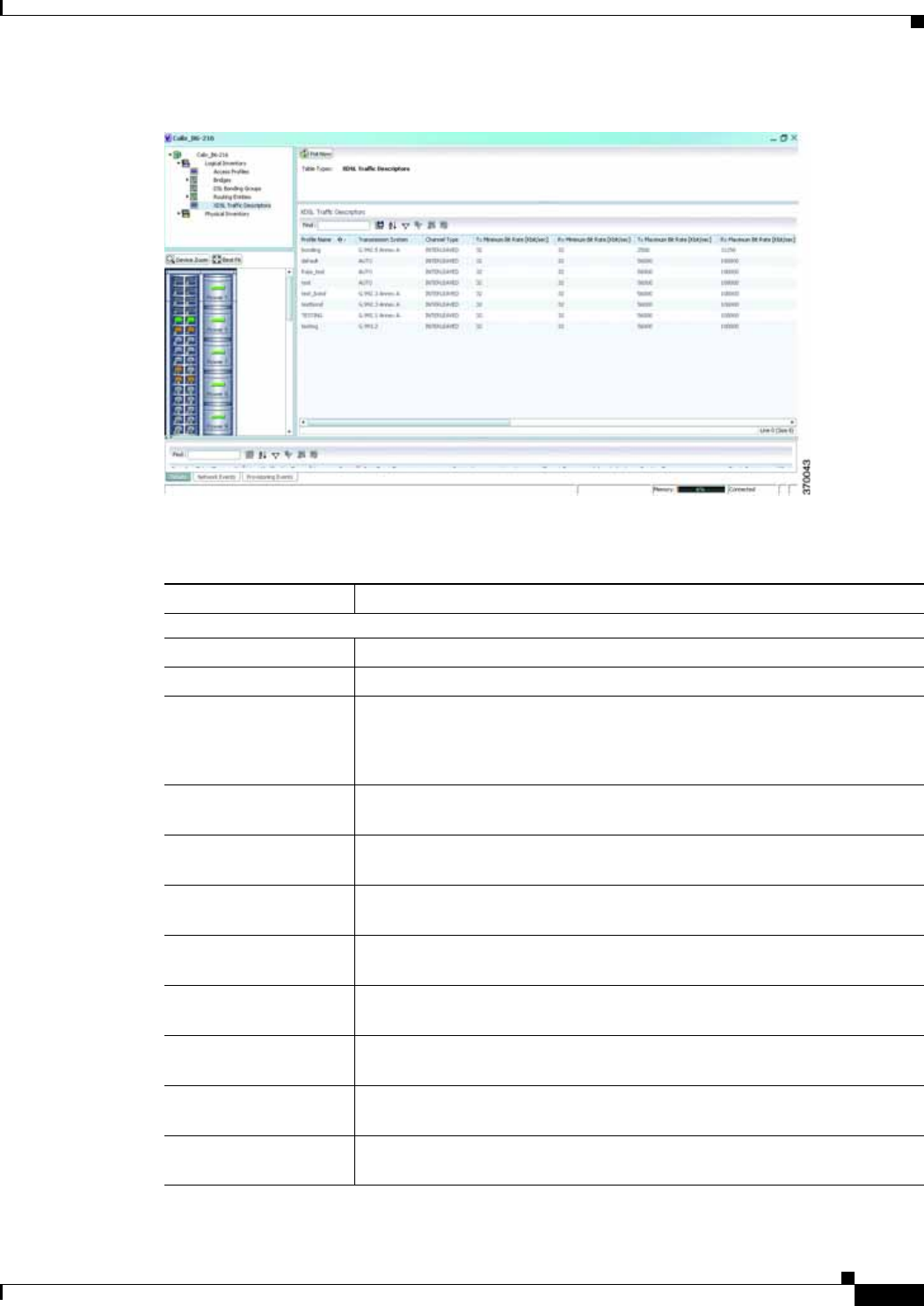
28-3
Cisco Prime Network 4.0 User Guide
OL-29343-01
Chapter 28 Monitoring ADSL2+ and VDSL2 Technology Enhancements User Roles Required to Work with ADSL2+/VDSL2 Technologies
Figure 28-1 XDSL Traffic Descriptor Details
Table 28-2 describes the XDSL Traffic Descriptor details.
Table 28-2 XDSL Traffic Descriptor Details
Field Description
XDSL Traffic Descriptors
Profile Name The name of the ADSL2+/VDSL2 profile.
Transmission System The operating mode of the transmission system.
Channel Type The type of physical channel, which can be any one of the following:
• Fast
• Interleaved
Tx Minimum Bit Rate
[Kbit/sec] The minimum bit rate (in terms of kilobits per second) transmitted for
adaptive bit rate.
Rx Minimum Bit Rate
[Kbit/sec] The minimum bit rate (in terms of kilobits per second) received for adaptive
bit rate.
Tx Maximum Bit Rate
[Kbit/sec] The maximum bit rate (in terms of kilobits per second) transmitted for
adaptive bit rate.
Rx Maximum Bit Rate
[Kbit/sec] The maximum bit rate (in terms of kilobits per second) received for adaptive
bit rate.
Tx Target Noise Margin
[dB] The target amount of noise (in decibel) transmitted by XDSL TU-C/TU-R.
Rx Target Noise Margin
[dB] The target amount of noise (in decibel) received by XDSL TU-C/TU-R.
Tx Minimum Noise
Margin [dB] The minimum amount of noise (in decibel) transmitted by XDSL
TU-C/TU-R.
Rx Minimum Noise
Margin [dB] The minimum amount of noise (in decibel) received by XDSL TU-C/TU-R.

28-4
Cisco Prime Network 4.0 User Guide OL-29343-01
Chapter 28 Monitoring ADSL2+ and VDSL2 Technology Enhancements
User Roles Required to Work with ADSL2+/VDSL2 Technologies
Viewing the ADSL2+/VDSL2 Details for a Device
The physical inventory details for a device displays the location information as well as the XDSL support
details for ADSL2+ and VDSL2 devices,
To view the physical inventory details for a device:
Step 1 Right-click the required device in Prime Network Vision and choose Inventory.
Step 2 Expand the Physical Inventory node.
Step 3 Choose the port and the following details are displayed in the content pane:
• Location Details—This section displays the Device Type, Location, Port Alias, and Status of the
device. It also indicates whether alarms must be sent for any event or alarm.
• ATM on port—This section displays the Asynchronous Transfer Mode details for the port.
• PTM on port—This section displays the Packet Transfer Mode (PTM) details for the port. The PTM
section displays the following information:
–
Encapsulation Type
–
TPS-TC Admin Mode—Will be displayed only for VDSL line cards.
–
TPS-TC Oper Mode—Will be displayed only for VDSL line cards.
Note The ATM on Port and PTM on Port sections will not be displayed if the port is bonded to a DSL
group or if the TPS-TC Admin Mode is specified as Auto and the TPS-TC Oper Mode is
specified as Unknown.
• XDSL/ADSL2/2+—This section displays the XDSL support details. These support details include
the Administrative and Operating statuses, Operating Mode, Aggregation Group, the various Bit
rates and Noise margins.
Tx Maximum Noise
Margin [dB] The maximum amount of noise (in decibel) transmitted by XDSL
TU-C/TU-R.
Rx Maximum Noise
Margin [dB] The maximum amount of noise (in decibel) received by XDSL TU-C/TU-R.
Transmission System The operating mode of the transmission system.
XDSL2 Line Profile The XDSL2 line profile that must be used.
Note This field is applicable only for VDSL2 technology.
Upstream Band 0 Mask The XDSL2 upstream band 0 mask.
Note This field is applicable only for VDSL2 technology.
Table 28-2 XDSL Traffic Descriptor Details
Field Description
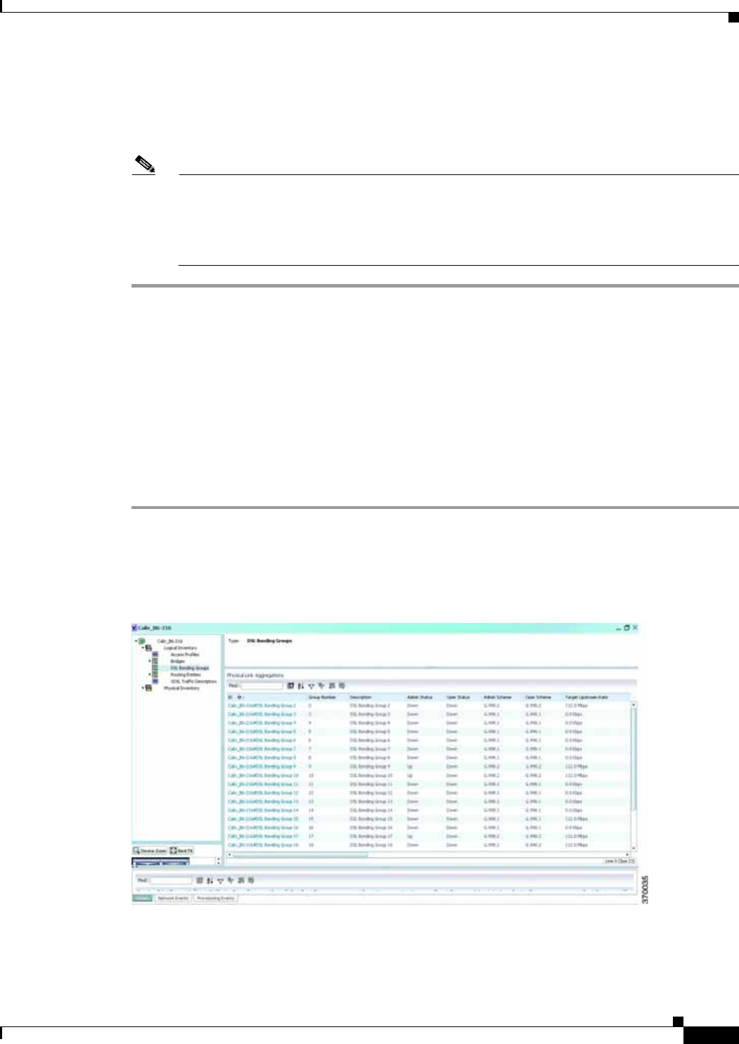
28-5
Cisco Prime Network 4.0 User Guide
OL-29343-01
Chapter 28 Monitoring ADSL2+ and VDSL2 Technology Enhancements User Roles Required to Work with ADSL2+/VDSL2 Technologies
The Operating Mode indicates whether the device is an ADSL2 or VDSL 2 device. The
Aggregation Group indicates whether the port is associated to a DSL bonding group. This is a link,
which when clicked will take you to the relevant bonding group in the DSL Bonding Group
node.For more information about the attributes in this section, refer to Table 28-2.
Note The name of this section changes based on the value in the Operating Mode field. If the value
in the Operating Mode field is None, then this section is titled XDSL. If the value in this field
refers to a ADSL device (for example G.992.5 Annex A), then this section is titled ADSL Ver
2/2+. If the value in this field refers to a VDSL device (for example G.993.2), then this section
is titled VDSL Ver2.
Viewing the DSL Bonding Group Configuration Details
Channel bonding is a computer networking arrangement in which two or more network interfaces on a
host computer are combined for redundancy or increased throughput. Similarly, multiple DSL lines can
be bonded to give higher bandwidth.
A bonded DSL uses multiple DSL connections and aggregates the bandwidth together to increase the
speed of upload and download process.
To view the DSL bonding group details:
Step 1 Right-click the required device in Prime Network Vision and choose Inventory.
Step 2 Expand the Logical Inventory node and choose DSL Bonding Groups. The relevant details are
displayed in the content pane as shown in Figure 28-2.
Figure 28-2 DSL Bonding Group Node

28-6
Cisco Prime Network 4.0 User Guide OL-29343-01
Chapter 28 Monitoring ADSL2+ and VDSL2 Technology Enhancements
User Roles Required to Work with ADSL2+/VDSL2 Technologies
Table 28-3 describes the DSL Bonding Group details.
Table 28-3 DSL Bonding Group Details
Field Description
Physical Link Aggregations
ID The unique identification code of the DSL bonding group.
Group Number The group number for the DSL bonding group.
Description The description of the DSL bonding group.
Containing TPs The termination points associated with the DSL bonding group.
Admin Status The administrative status of the DSL bonding group, which can be any one
of the following:
• Up
• Down
Oper Status The operative status of the DSL bonding group, which can be any one of the
following:
• Up
• Down
Admin Scheme The administrative scheme of the DSL bonding group, which can be any one
of the following:
• G998.1
• G998.2
• Unknown
Oper Scheme The operative scheme of the DSL bonding group, which can be any one of
the following:
• G998.1
• G998.2
• Unknown
Target Upstream Rate The target upstream rate (in kbps or mbps) of the DSL bonding group.
Target Downstream
Rate The target downstream rate (in kbps or mbps) of the DSL bonding group.
Upstream Rate The current upstream rate (in kbps or mbps) of the DSL bonding group.
Downstream Rate The current downstream rate (in kbps or mbps) of the DSL bonding group.
Minimum Upstream
Rate The minimum upstream rate (in kbps or mbps) of the DSL bonding group.
Minimum Downstream
Rate The minimum downstream rate (in kbps or mbps) of the DSL bonding group.
Number of Aggregated
Ports The number of aggregated ports that is configured in the DSL bonding
group.
Maximum Aggregated
Ports The maximum number of aggregated ports that can be configured in the DSL
bonding group.

28-7
Cisco Prime Network 4.0 User Guide
OL-29343-01
Chapter 28 Monitoring ADSL2+ and VDSL2 Technology Enhancements User Roles Required to Work with ADSL2+/VDSL2 Technologies
Peer Admin Scheme The peer administrative scheme of the DSL bonding group, which can be any
one of the following:
• G998.1
• G998.2
• Unknown
Peer Oper Scheme The peer operational scheme of the DSL bonding group, which can be any
one of the following:
• G998.1
• G998.2
• Unknown
Designated End Point The designated end point of the DSL bonding group.
Maximum Peer
Aggregated Ports The maximum number of peer aggregated ports that is configured in the DSL
bonding group.
Discovery Code The unique 6-octet-long code that is used by the Discovery function of the
Generic Bonding Sub-layer port.
G988.2 Properties
Control Protocol Type The type of control protocol currently operating on the G.bond port, which
can be any one of the following:
• BACP
• G.HS
This field defaults to G.HS.
Note This field is available only if the Oper Scheme for the DSL bonding
group is specified as G.988.2.
PTM Encapsulation
Type The Packet Transfer Mode-Transport Convergence Layer (PTM-TC)
encapsulation type supported by the G.bond port, which can be any one of
the following:
• 64/65-octet
• HDLC
Note This field is available only if the Oper Scheme for the DSL bonding
group is specified as G.988.2.
Is BACP Supported Indicates whether the Bonding Aggregation Control Protocol (BACP) is
supported y the G.bond port.
Note This field is available only if the Oper Scheme for the DSL bonding
group is specified as G.988.2.
Table 28-3 DSL Bonding Group Details
Field Description
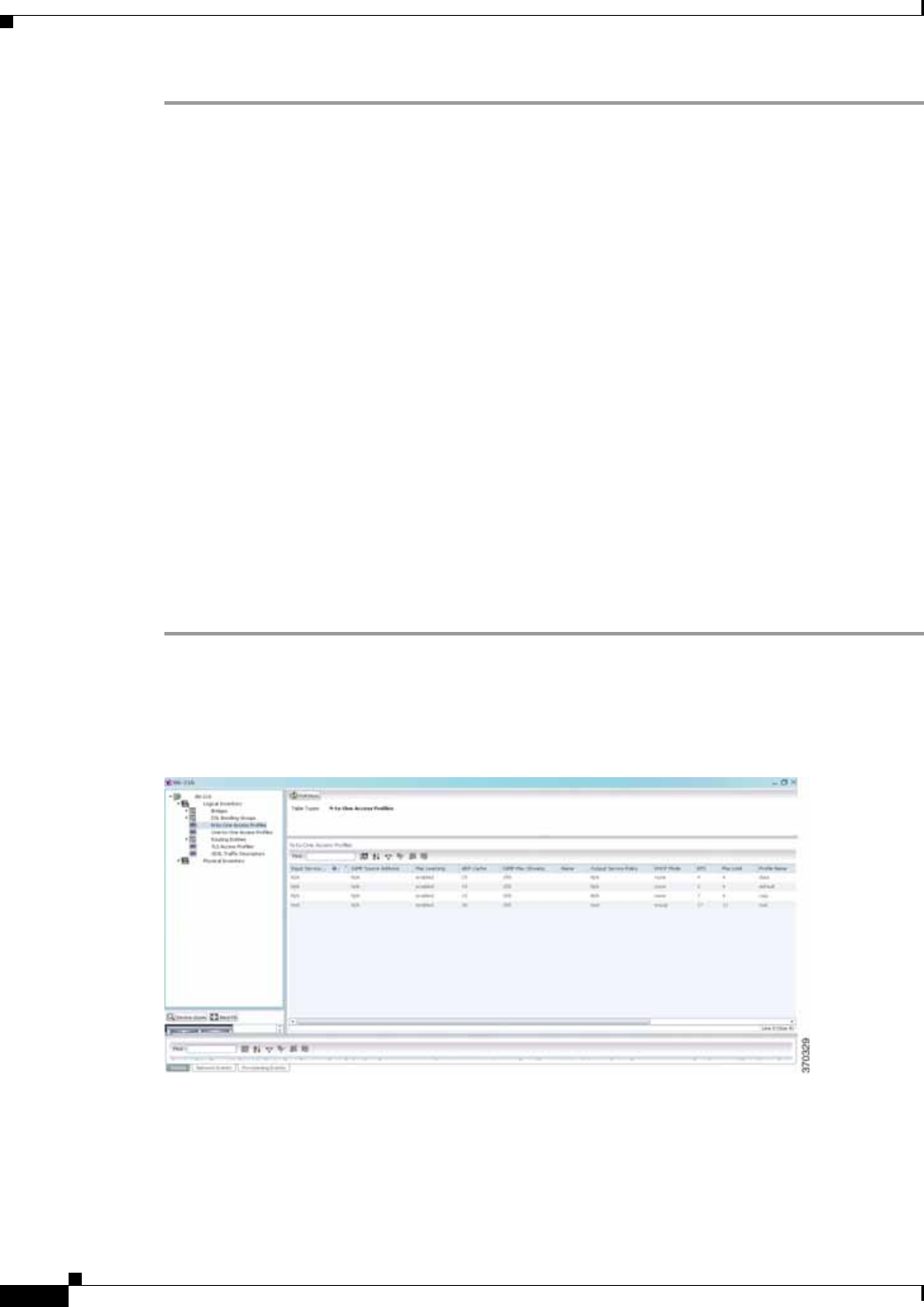
28-8
Cisco Prime Network 4.0 User Guide OL-29343-01
Chapter 28 Monitoring ADSL2+ and VDSL2 Technology Enhancements
User Roles Required to Work with ADSL2+/VDSL2 Technologies
Viewing Transport Models Supported by ADSL2+ and VDSL2
In Prime Network, the following transport models are supported in the ADSL2+ and VDSL2
technologies:
• N-to-One—In this most commonly used model, a Service VLAN tag (S-Vid) is assigned to a service
throughout the network. The destination is determined by the MAC address of the device and the
service VLAN at the edge of the network. This transport model is supported on ADSL2+ and
VDSL2 line cards.
• One-to-One—In this model, the destination is determined by a pair of VLAN tags, which must be
unique throughout the network. This transport model is supported on B6 VDSL2 line cards.
• Transparent LAN Service (TLS) —This model allows transparency to the business customers while
transporting business traffic between geographically disperse business endpoints. The traffic that is
transported by the infrastructure that interconnects the locations is transparent to the carrier network
(including protocols such as STP, unicast and multicast protocols). The traffic can be of any format
and often includes VLAN tagged traffic.
Viewing the N-to-One Access Profile
To view the N-to-One access profile:
Step 1 Right-click the required device in Prime Network Vision and choose Inventory.
Step 2 Expand the Logical Inventory node and choose N-to-One Access Profiles. The relevant details are
displayed in the content pane as shown in Figure 28-3.
Figure 28-3 N-to-One Access Profile

28-9
Cisco Prime Network 4.0 User Guide
OL-29343-01
Chapter 28 Monitoring ADSL2+ and VDSL2 Technology Enhancements User Roles Required to Work with ADSL2+/VDSL2 Technologies
Table 28-4 describes the N-to-One Access Profile details.
Table 28-4 N-to-One Access Profiles
Field Description
Table Types The type of access profile, which in this instance is N-to-One Access
Profiles.
N-to-One Access Profiles
Input Service The input service policy applicable to the device.
IGMP Source Address The Internet Group Management Protocol (IGM) source address.
Mac Learning Indicates whether the Mac Learning feature is enabled for the device.
ARP Cache The Address Resolution Protocol (ARP) cache of the device.
Note ARP converts an IP address to its corresponding physical network
address, which is usually implemented in the device drivers of the
network operating systems. When a device wants to send data to
another device over ethernet, it must first determine the MAC
address of the target device. These IP to MAC address mappings are
derived from the ARP cache maintained on each device.
IGMP Max Streams The maximum Internet Group Management Protocol (IGMP) stream value.
Name The name of the N-to-One access profile.
Output Service Policy The output service policy applicable to the device.
DHCP Mode The Dynamic Host Configuration Protocol (DHCP) mode applicable to the
device.
EPS The Ethernet Protection Switching (EPS) VLAN tag assigned to the device.
Note The VLAN tag numbers can be any value between 2 and 122 when
B6 line cards access rings. When the B6-450 is used on aggregation
rings, it supports VLAN tag numbers between 2 and 1000.
Mac Limit The maximum number of MAC addresses allowed for the service.
Profile Name The name of the access profile.
Input Service Policy The name of the service policy that is assigned to the access profile as an
input policy. This is a rate-limiting policy that controls and limits all unicast
incoming traffic from the B6 card to the subscriber.
Output Service Policy The name of the service policy that is assigned to the access profile as an
output policy. This is a rate-limiting policy that controls and limits all unicast
outgoing traffic to the B6 card from the subscriber.
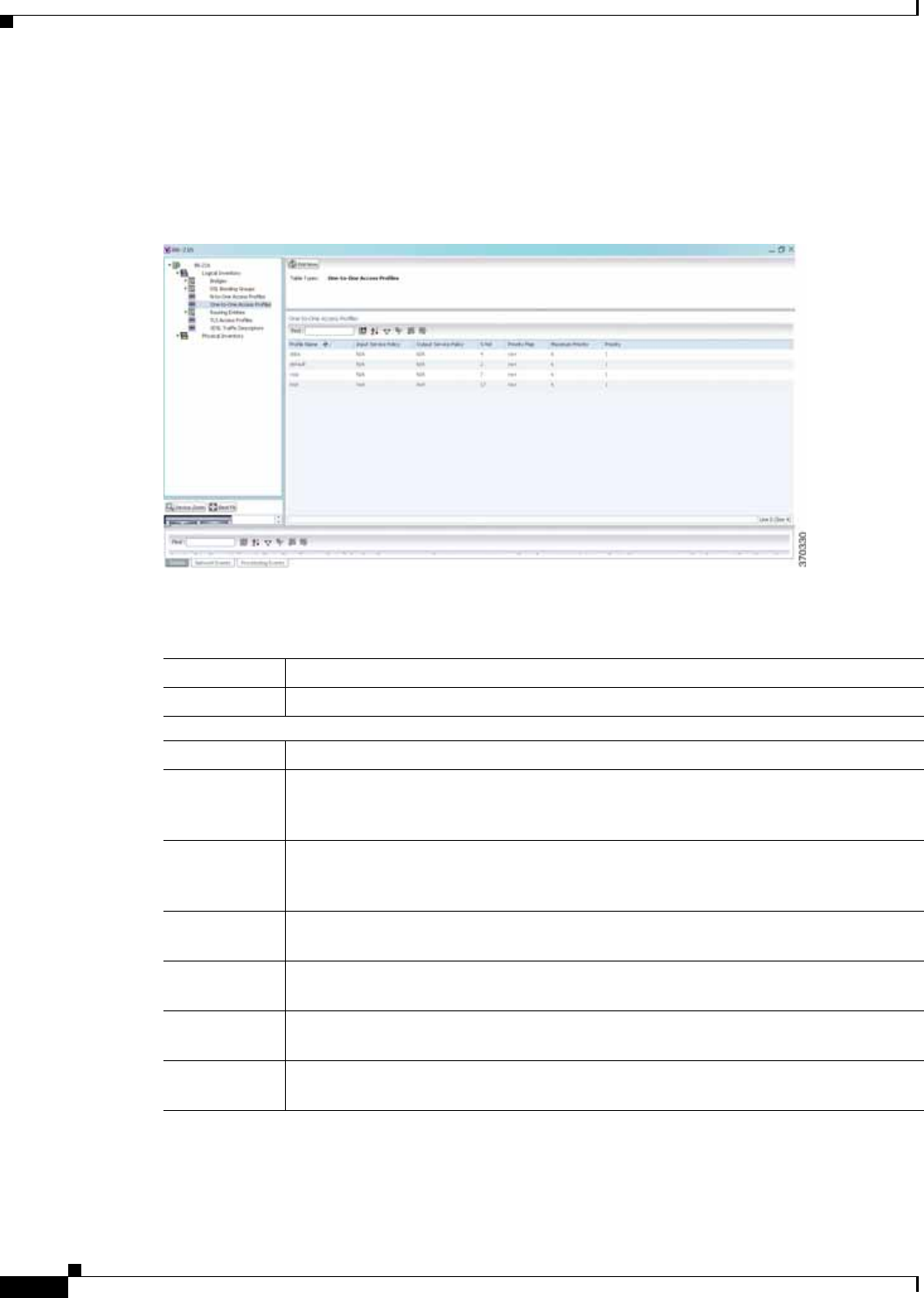
28-10
Cisco Prime Network 4.0 User Guide OL-29343-01
Chapter 28 Monitoring ADSL2+ and VDSL2 Technology Enhancements
User Roles Required to Work with ADSL2+/VDSL2 Technologies
Viewing the One-to-One Access Profile
To view the One-to-One access profile details, expand the logical inventory and choose One-to-One
Access Profiles.
Figure 28-4 One-to-One Access Profile
Table 28-5 describes the N-to-One Access Profile details.
Table 28-5 N-to-One Access Profiles
Field Description
Table Types The type of access profile, which in this instance is One-to-One Access Profile.
One-to-One Access Profiles
Profile Name The name of the One-to-one access profile.
Input Service
Policy The name of the service policy that is assigned to the access profile as an input policy.
This is a rate-limiting policy that controls and limits all unicast incoming traffic from
the B6 card to the subscriber.
Output Service
Policy The name of the service policy that is assigned to the access profile as an output policy.
This is a rate-limiting policy that controls and limits all unicast outgoing traffic to the
B6 card from the subscriber.
S-Vid The unique Subscriber VLAN identification code. This code can be any value between
2 and 122.
Priority Map The name of the 802.1p priority map, which is available in the DSCP-to-DOTP
mapping profile.
Maximum
Priority The maximum 802.1 priority level.
Priority The 802.1 priority level configured and applied to the incoming S-VID packet. This
level can be any value between 0 and 6.

28-11
Cisco Prime Network 4.0 User Guide
OL-29343-01
Chapter 28 Monitoring ADSL2+ and VDSL2 Technology Enhancements User Roles Required to Work with ADSL2+/VDSL2 Technologies
Viewing the TLS Access Profile
To view the TLS access profile details:
Step 1 Right-click the required device in Prime Network Vision and choose Inventory.
Step 2 Expand the Logical Inventory node and choose TLS Access Profiles. The relevant details are displayed
in the content pane as shown in Figure 28-5.
Figure 28-5 TLS Access Profiles
Table 28-6 describes the N-to-One Access Profile details.
Table 28-6 N-to-One Access Profiles
Field Description
Table Types The type of access profile, which in this instance is TLS Access Profile.
TLS Access Profiles
Profile Name The name of the TLS access profile.
Input Service Policy The name of the service policy that is assigned to the access profile as an
input policy. This is a rate-limiting policy that controls and limits all unicast
incoming traffic from the B6 card to the subscriber.
Output Service Policy The name of the service policy that is assigned to the access profile as an
output policy. This is a rate-limiting policy that controls and limits all unicast
outgoing traffic to the B6 card from the subscriber.
S-Vid The unique Subscriber VLAN identification code. This code can be any
value between 2 and 122.
Mac Limit The maximum number of MAC addresses allowed for the specific service.
Maximum Priority The maximum 802.1 priority level.
Priority The 802.1 priority level configured and applied to the incoming S-VID
packet. This level can be any value between 0 and 6.

28-12
Cisco Prime Network 4.0 User Guide OL-29343-01
Chapter 28 Monitoring ADSL2+ and VDSL2 Technology Enhancements
User Roles Required to Work with ADSL2+/VDSL2 Technologies

A-1
Cisco Prime Network 4.0 User Guide
OL-29343-01
APPENDIX
REVIEW
DRAFT
—
CISCO
CONFIDENTIAL
A
Icon and Button Reference
The following topics identify the buttons, icons, and badges used in Cisco Prime Network Vision (Prime
Network Vision) and Cisco Prime Network Events (Prime Network Events):
• Icons, page A-1
• Links, page A-10
• Severity Icons, page A-13
• Buttons, page A-14
• Badges, page A-19
Icons
The following topics describe the icons used in Prime Network Vision:
• Network Element Icons, page A-2
• Business Element Icons, page A-4
• Logical Inventory Icons, page A-7
• Physical Inventory Icons, page A-10
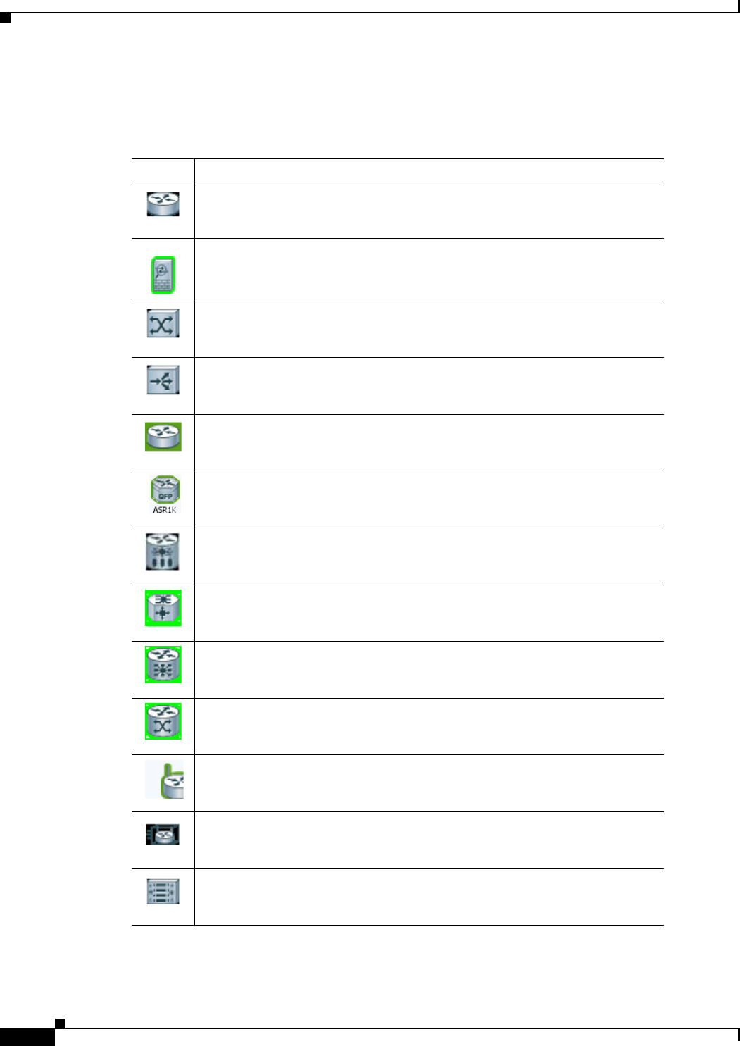
REVIEW DRAFT—CISCO CONFIDENTIAL
A-2
Cisco Prime Network 4.0 User Guide OL-29343-01
Appendix A Icon and Button Reference
Icons
Network Element Icons
Table A-1 Prime Network Vision Network Element Icons
Icon Network Element
Access pseudowire
Router
Cisco ASA device
ATM switch
Basic rate access (BRA)
Cisco 7600 series router
Cisco ASR 1000 series router
Cisco ASR 5000 series router
Cisco ASR 9000 series router
Cisco CRS series router
Cisco IOS XR 12000 series router
Cisco MWR 3941
Cisco Nexus 1000 series
Cisco Unified Computing System (UCS) 6100 series
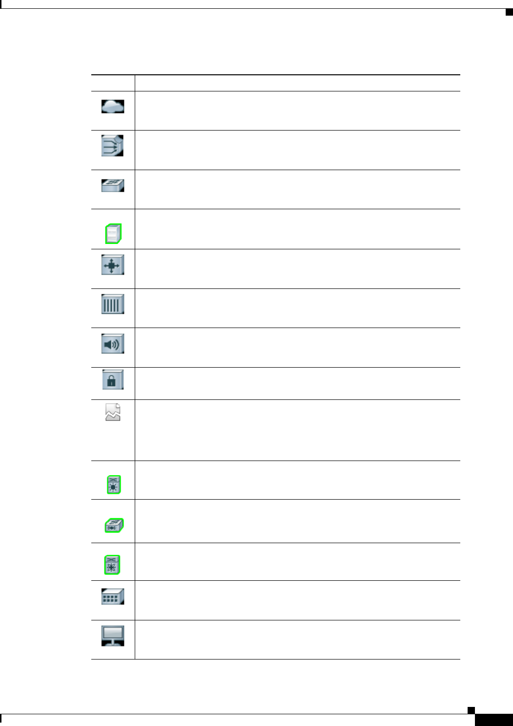
REVIEW DRAFT—CISCO CONFIDENTIAL
A-3
Cisco Prime Network 4.0 User Guide
OL-29343-01
Appendix A Icon and Button Reference Icons
Cloud
Digital subscriber line access multiplexer (DSLAM)
Ethernet switch
Generic Server
Generic SNMP device
Ghost, or unknown device
ICMP device
Lock, or security violation; viewable by a user with a higher permission level
Missing icon, displayed in either of the following situations:
• A device has been deleted via Prime Network Administration, but remains
in the map.
• A unique icon for an element (physical or logical) does not exist.
Cisco MDS device
Nexus 5000 Series device
Nexus 7000 Series device
Sun Netra server
PC
Table A-1 Prime Network Vision Network Element Icons (continued)
Icon Network Element
REVIEW DRAFT—CISCO CONFIDENTIAL
A-4
Cisco Prime Network 4.0 User Guide OL-29343-01
Appendix A Icon and Button Reference
Icons
Business Element Icons
Printer
RFGW-10 device
Service control switch
UBR 10012 device
UCS C Series device
vCenter device
Virtual Security Gateway (VSG) device
WiFi element
Table A-2 Prime Network Vision Business Element Icons
Icon Business Element
Aggregation or root node
Backup pseudowire edge
Business IP interface
Connection termination point (TP)
Ethernet flow point (EFP)
MToP service
Table A-1 Prime Network Vision Network Element Icons (continued)
Icon Network Element
REVIEW DRAFT—CISCO CONFIDENTIAL
A-5
Cisco Prime Network 4.0 User Guide
OL-29343-01
Appendix A Icon and Button Reference Icons
Customer
EFP cross-connect
Ethernet service
Ethernet virtual connection (EVC)
Label-Switched Path (LSP) endpoint
LSP midpoint
Network LSP
Network pseudowire
Network TP tunnel
Network VLAN
Protected LSP
Pseudowire edge
Pseudowire switching entity
Site
Table A-2 Prime Network Vision Business Element Icons (continued)
Icon Business Element
REVIEW DRAFT—CISCO CONFIDENTIAL
A-6
Cisco Prime Network 4.0 User Guide OL-29343-01
Appendix A Icon and Button Reference
Icons
Subnet
Switching entity
TP tunnel endpoint
Virtual router
VPLS forward
VPLS instance
VPN
Working LSP
Table A-2 Prime Network Vision Business Element Icons (continued)
Icon Business Element

REVIEW DRAFT—CISCO CONFIDENTIAL
A-7
Cisco Prime Network 4.0 User Guide
OL-29343-01
Appendix A Icon and Button Reference Icons
Logical Inventory Icons
Table A-3 describes the icons used in logical inventory.
Table A-3 Logical Inventory Icons
Icon Logical Inventory Item
Access Lists
ATM Traffic Profiles
Bidirectional Forwarding Detection
(BFD)
Cisco Discovery Protocol (CDP)
Clock
DTI Client
Ethernet LMI
Fiber Node
Frame Relay Traffic Profiles
IP SLA
IP Pool
Dynamic Config Templates
QoS
Link Layer Discovery Protocol (LLDP)
Modular OS
Operating System
Operations, Administration, and
Maintenance (OAM)
Resilient Ethernet Protocol (REP)
Session Border Controller
Spanning Tree Protocol
Tunnel Traffic Descriptors
BBA Groups
Policy Container
Access Gateway
ARP Entity
Bridges
Ethernet Link Aggregation
GRE Tunnels
ICCP Redundancy container
IMA Groups
Local Switching
LSEs
MLPPP
MPBGPs
Multicast
Multiple Spanning Tree protocol (MST)
instance
OSPF Processes
Pseudowires
Routing Entities
Traffic Engineering Tunnels
VC Switching Entities
VRFs
VSIs
VPC Domain
BNG
DHCP Service
AAA Group
MAC Domain
Narrowband Channels
QAM Domain
Wideband Channels
REVIEW DRAFT—CISCO CONFIDENTIAL
A-8
Cisco Prime Network 4.0 User Guide OL-29343-01
Appendix A Icon and Button Reference
Icons
Probe
Y.1731 Probe
Bridge
Connectivity Fault Management (CFM) Maintenance Association
CFM Maintenance Domain
Connectivity Fault Management
Context, for devices that support multiple virtual contexts
Cross-VRF
Encapsulation
ICCP Redundancy group
Inverse Multiplexing over ATM (IMA) group
Label switching
Layer 2 Tunnel Protocol (TP) peer
Logical inventory
Virtual Switch Interface (VSI)
Table A-3 Logical Inventory Icons (continued)
Icon Logical Inventory Item

REVIEW DRAFT—CISCO CONFIDENTIAL
A-9
Cisco Prime Network 4.0 User Guide
OL-29343-01
Appendix A Icon and Button Reference Icons
VLAN Trunk Protocol (VTP)
Mobile node
GGSN / SAE-GW / P-GW / S-GW / EGTP / GTPP container
GGSN / SAE-GW / P-GW / S-GW / EGTP / GTPP
GTPU
APN container
APN
ACS
Operator policy
APN profile / APN remap
Virtual data center
Data store
Data stores container
Host server or hypervisor
Host servers/hypervisor container
Virtual machine
Table A-3 Logical Inventory Icons (continued)
Icon Logical Inventory Item
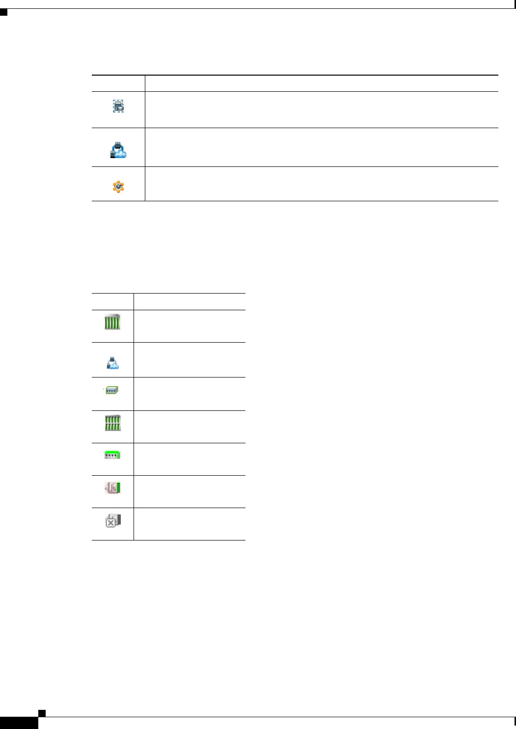
REVIEW DRAFT—CISCO CONFIDENTIAL
A-10
Cisco Prime Network 4.0 User Guide OL-29343-01
Appendix A Icon and Button Reference
Links
Physical Inventory Icons
Table A-4 describes the icons used in physical inventory.
Links
The following sections describe link icons and characteristics:
• Link Icons, page A-11
• Link Colors, page A-12
• Link Characteristics, page A-12
Virtual machines container
VSAN
Compute Resource Pool
Table A-3 Logical Inventory Icons (continued)
Icon Logical Inventory Item
Table A-4 Physical Inventory Icons
Icon Device
Chassis
Cluster
Satellite
Shelf
Slot/Subslot
Port/Logical Port
Unmanaged Port

REVIEW DRAFT—CISCO CONFIDENTIAL
A-11
Cisco Prime Network 4.0 User Guide
OL-29343-01
Appendix A Icon and Button Reference Links
Link Icons
Table A-5 identifies the available link types and their representation in Prime Network Vision.
Table A-5 Prime Network Vision Link Icons
Icon Description Icon Description
Asynchronous Transfer Mode Unknown
Bidirectional Forwarding
Detection Physical layer
Border Gateway Protocol Private Network-to-Network
Interface
Business link Point-to-Point Protocol
Ethernet Pseudowire
Frame Relay Serial
Generic Routing Encapsulation MPLS TE Tunnel
Internal MPLS TP Tunnel
IP VLAN
Link aggregation group IPv6 VPN over IPv4-MPLS
Multilink Point-to-Point
Protocol VPN
MPLS Fiber Channel
Entity Association
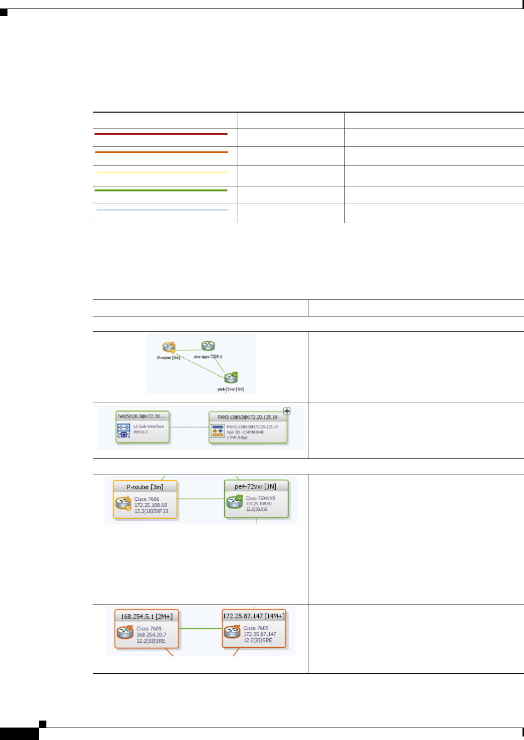
REVIEW DRAFT—CISCO CONFIDENTIAL
A-12
Cisco Prime Network 4.0 User Guide OL-29343-01
Appendix A Icon and Button Reference
Links
Link Colors
Link Characteristics
Table A-6 Link Colors and Severity
Color Severity Description
Critical Critical alarm is on the link.
Major Major alarm is on the link.
Minor Minor alarm is on the link.
Normal Link is operating normally.
Selected Link is selected.
Table A-7 Link Characteristics
Example Description
Solid Line vs. Dashed Line
Solid line—Physical, topological, or service link,
such as a link between two devices.
Dashed line—Association or business link
between such elements as EVCs, VPLS service
instances, or VPN components.
Link Widths
Normal—Contains links of the same group.
Available groups are:
• Business
• GRE
• MPLS-TP
• Pseudowire
• VLAN
• All others
Wide—Aggregated links that contain links of
different groups.
When viewing a map at a low zoom level,
aggregated links cannot be distinguished in the
GUI.
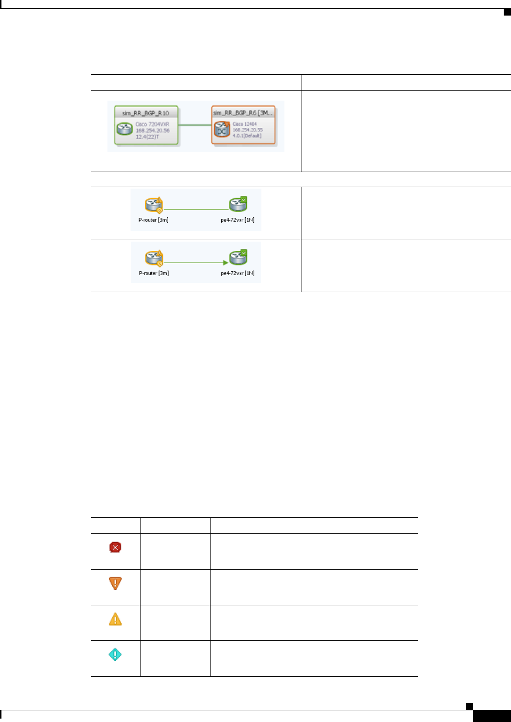
REVIEW DRAFT—CISCO CONFIDENTIAL
A-13
Cisco Prime Network 4.0 User Guide
OL-29343-01
Appendix A Icon and Button Reference Severity Icons
Severity Icons
Table A-8 identifies the severity icons used in Prime Network Events and Prime Network Vision.
The icons and colors are used as follows:
• The icons are used to indicate the severity of alarms in Prime Network Events and tickets in the
Prime Network Vision ticket pane.
• The icons are used as badges in Prime Network Vision maps to indicate the highest severity alarm
that is not acknowledged for the associated network element.
• The colors are used with network elements in Prime Network Vision to indicate the severity of the
highest uncleared ticket on the element.
• The colors are used with links in Prime Network Vision to indicate the severity of the alarm on the
link. For more information, see Link Colors, page A-12.
Tunnel—The center color represents the severity
of any alarms on the link.
Arrowhead vs. No Arrowhead
No arrowhead—Bidirectional link.
Arrowhead Unidirectional link, with the flow in
the direction of the arrowhead.
Table A-7 Link Characteristics (continued)
Example Description
Table A-8 Severity Indicators
Icon Color Severity
Red Critical
Orange Major
Yellow Minor
Light Blue Warning
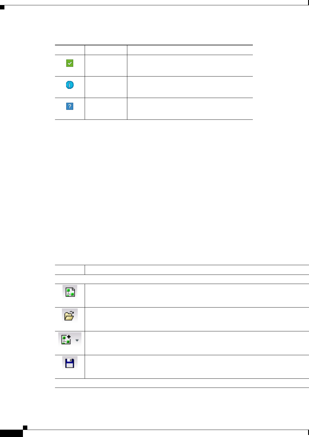
REVIEW DRAFT—CISCO CONFIDENTIAL
A-14
Cisco Prime Network 4.0 User Guide OL-29343-01
Appendix A Icon and Button Reference
Buttons
Buttons
The following topics describe the buttons used in Prime Network Vision:
• Prime Network Vision Buttons, page A-14
• Table Buttons, page A-17
• Link Filtering Buttons, page A-17
• Prime Network Events Buttons, page A-18
• Ticket Properties Buttons, page A-18
• Report Manager Buttons, page A-19
Prime Network Vision Buttons
Green Cleared, Normal, or OK
Medium Blue Information
Dark Blue Indeterminate
Table A-8 Severity Indicators (continued)
Icon Color Severity
Table A-9 Prime Network Vision Buttons
Button Function
Map Options
Creates a new map in the database.
Opens a map saved in the database using the Open dialog box.
Adds a network element to the map or to the subnetwork selected in the navigation pane
and displayed in the content pane.
Saves the current map (the background and the location of devices) to the database.
Viewing Options
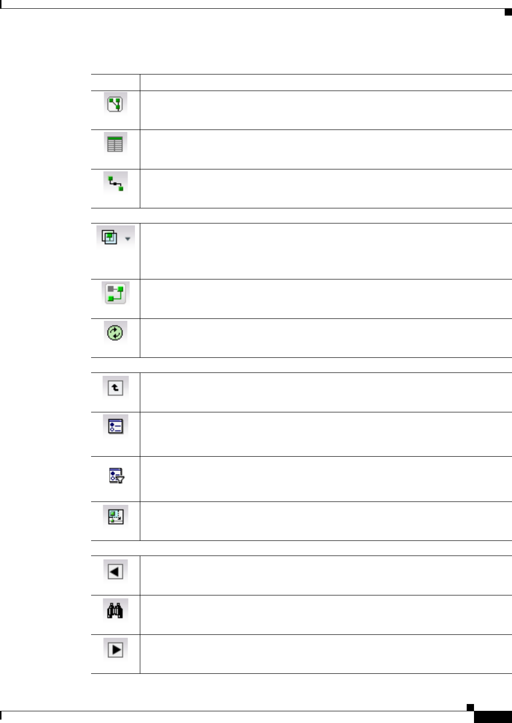
REVIEW DRAFT—CISCO CONFIDENTIAL
A-15
Cisco Prime Network 4.0 User Guide
OL-29343-01
Appendix A Icon and Button Reference Buttons
Displays the map view in the Prime Network Vision content pane (the button toggles when
selected or deselected).
Displays the list view in the Prime Network Vision content pane (the button toggles when
selected or deselected).
Displays the links view in the Prime Network Vision content pane (the button toggles when
selected or deselected).
Overlay Tools
Chooses and displays an overlay of a specific type on top of the elements displayed in the
content pane in the map view.
When an overlay is selected, all the elements and links that are part of the overlay are
colored, and those that are not part of the overlay are dimmed.
Displays or hides a previously defined overlay of a specific type on top of the elements
displayed in the content pane in map view.
Refreshes the overlay.
Navigation Tools
Moves up a level in the navigation pane and map pane to enable you to view different
information.
Opens the Link Filter dialog box, enabling you to display or hide different types of links
in the map and links views.
If a link filter is applied to the map, the Link Filter Applied button is displayed instead.
Indicates a link filter is currently applied to the map and opens the Link Filter dialog box
so you can remove or modify the existing link filter.
If no link filter is applied to the map, the Link Filter button is displayed instead.
Opens a window displaying an overview of the network.
Search Tools
Finds the previous instance of the search string entered in the Find in Map dialog box.
Opens the Find in Map dialog box, enabling you to find a device or aggregation in the map
by its name or IP address.
Finds the next instance of the search string entered in the Find in Map dialog box.
Table A-9 Prime Network Vision Buttons (continued)
Button Function
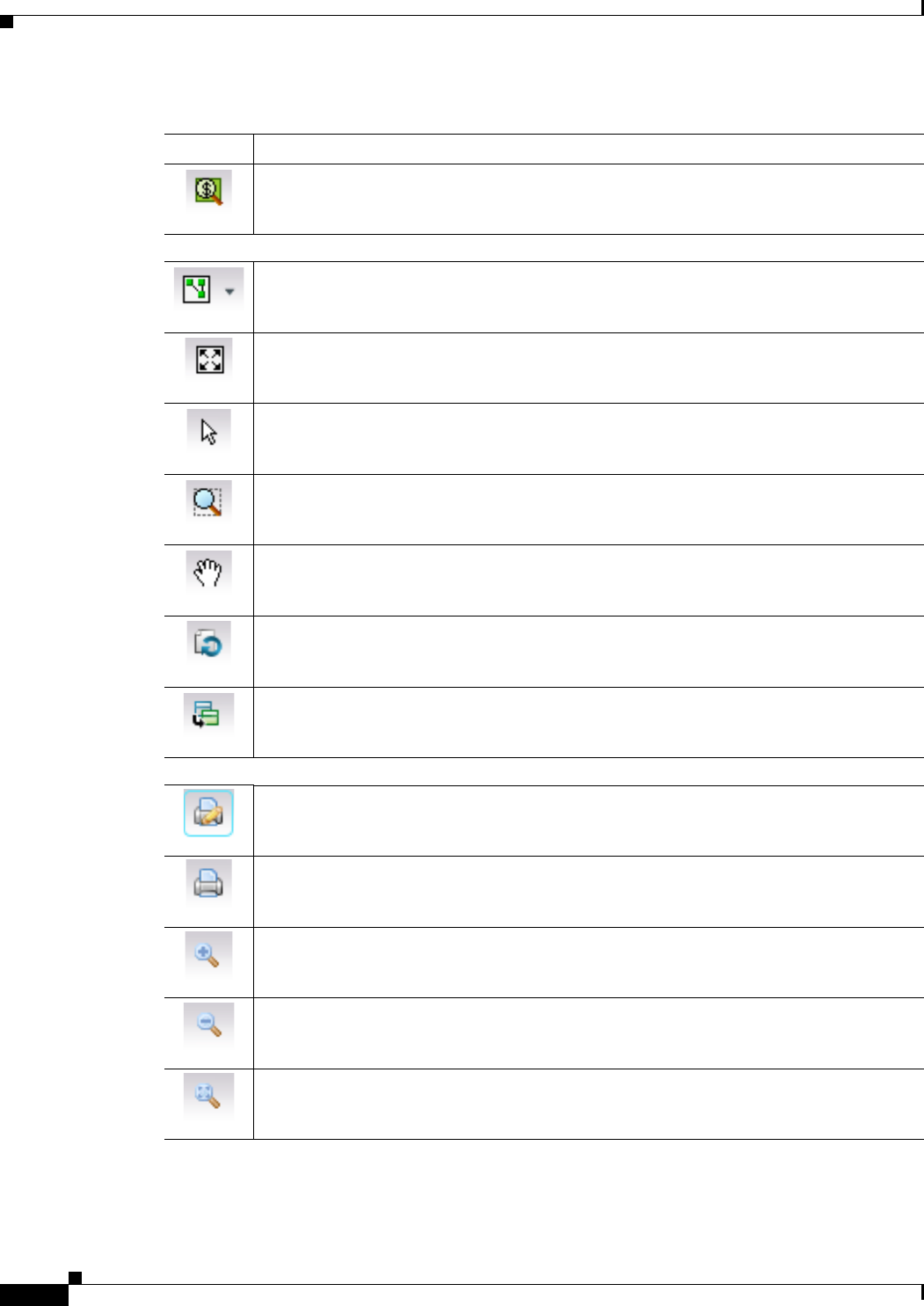
REVIEW DRAFT—CISCO CONFIDENTIAL
A-16
Cisco Prime Network 4.0 User Guide OL-29343-01
Appendix A Icon and Button Reference
Buttons
Opens the Find Business Tag dialog box, enabling you to find and detach a business tag
according to a name, key, or type.
Map Zoom and Layout Tools
Defines the way in which the NES are arranged in the Prime Network Vision map view:
circular, hierarchical, orthogonal, or symmetric.
Fits the entire subnetwork or map in the map pane.
Activates the normal selection mode.
Activates the zoom selection mode, which enables you to select an area in the map pane to
zoom in on by clicking and dragging.
Activates the pan mode, which enables you to move around in the map pane by clicking
and dragging.
Opens the Activation dialog box.
Opens the Activation List dialog box.
Print Preview Options
Opens the Printer Setup dialog box so you can specify your print settings.
Opens the Print dialog box so you can print the displayed network or map to the required
printer.
Zooms in on the network or map.
Zooms out of the network or map.
Displays the entire network or map in the Print Preview window.
Table A-9 Prime Network Vision Buttons (continued)
Button Function
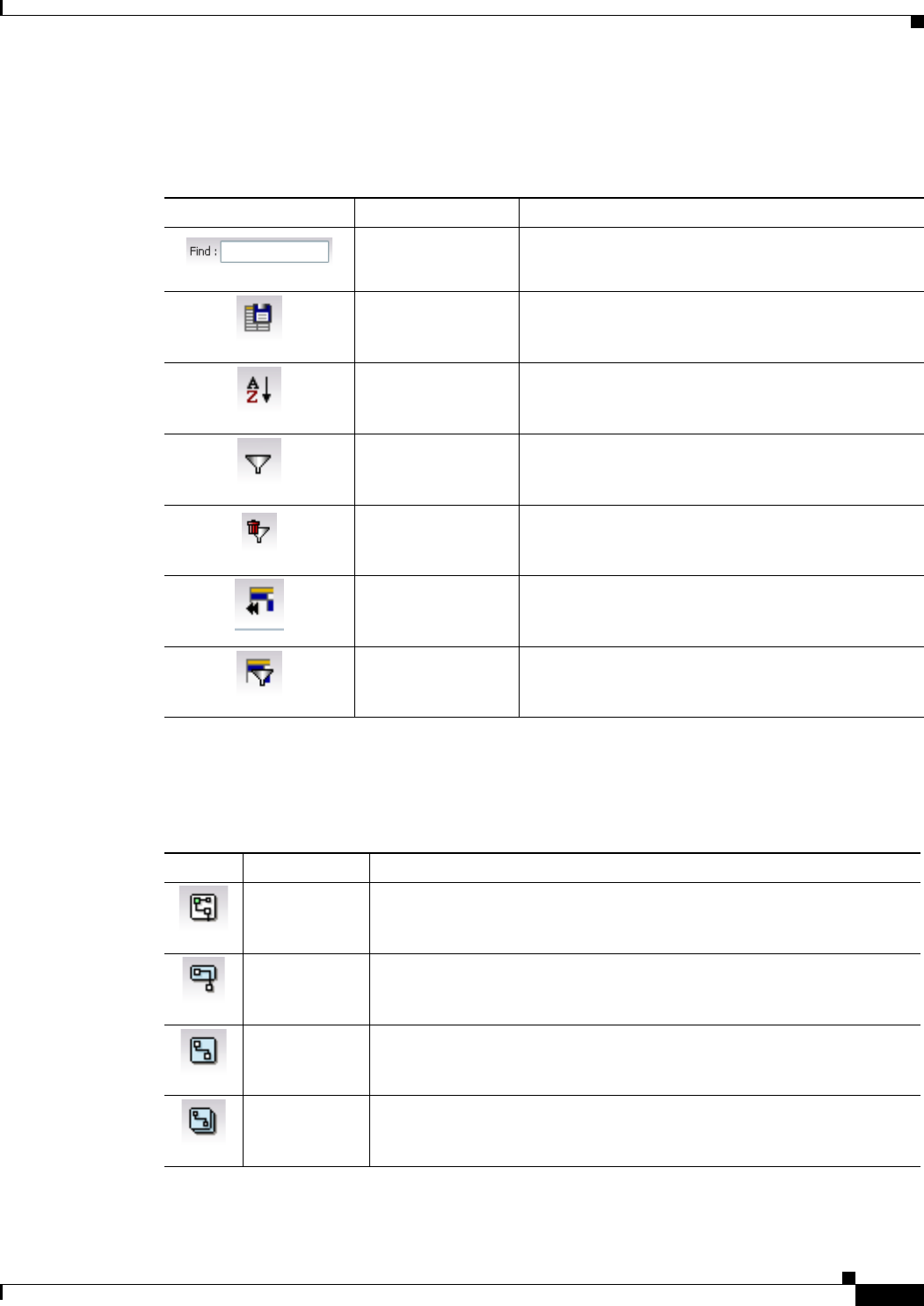
REVIEW DRAFT—CISCO CONFIDENTIAL
A-17
Cisco Prime Network 4.0 User Guide
OL-29343-01
Appendix A Icon and Button Reference Buttons
Table Buttons
Link Filtering Buttons
Table A-10 Table Buttons
Icon Name Description
Find Searches the current table for the string you enter.
Export to CSV Exports the information displayed in the list view.
Either the selected rows are exported, or, when
nothing is selected, the entire table is exported.
Sort Table Values Sorts the information displayed in the list view (for
example, according to element category).
Filter Filters the information displayed in the table by the
criteria you specify.
Clear Filter Clears the existing filter.
Show All Rows Displays all table rows that meet the current filtering
criteria.
Show Only Selected
Rows Displays only the rows that you select.
Table A-11 Link Filtering Buttons
Button Name Description
All Links Displays the complete list of links for the selected context (map or
aggregation). In other words, the list is not filtered and all the links are
displayed, including external links.
External Links Displays links with only one side of the link in this context (map or
aggregation) and the other side either not in the map or outside the
selected context.
Flat Links Displays the links currently visible on the map for the selected context
(map or aggregation), excluding any thumbnails.
Deep Links Displays the links for the current aggregation where both endpoints are
within the currently selected context.
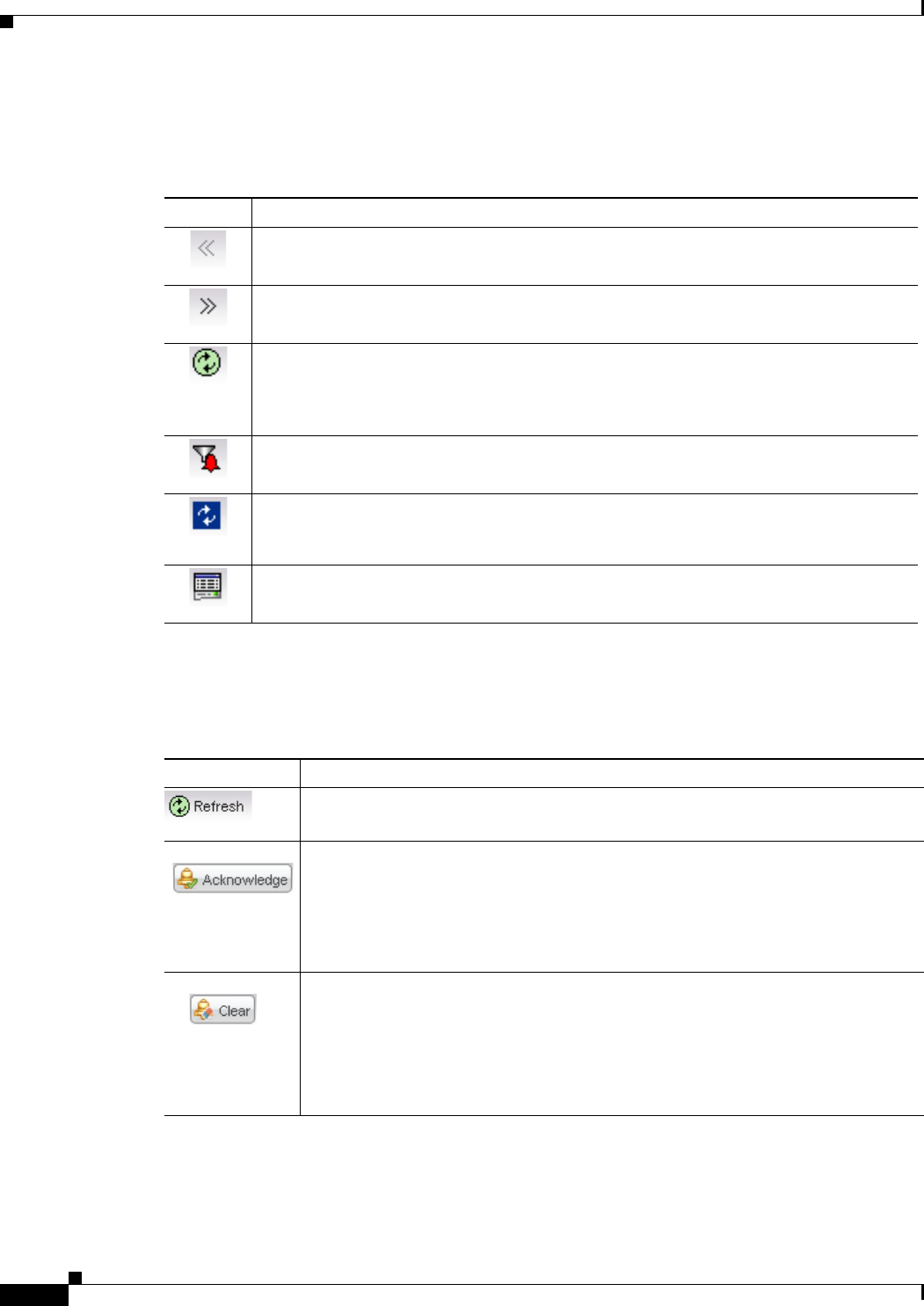
REVIEW DRAFT—CISCO CONFIDENTIAL
A-18
Cisco Prime Network 4.0 User Guide OL-29343-01
Appendix A Icon and Button Reference
Buttons
Prime Network Events Buttons
Ticket Properties Buttons
Table A-12 Prime Network Events Buttons
Button Function
Displays the previous page of events in the Prime Network Events window.
Displays the next page of events in the Prime Network Events window.
Refreshes the events displayed in the log by querying the database. If a filter is active, the
refresh is done according to the filter. The log returns to the beginning of the list,
displaying the events in ascending or descending order depending on the order of the
current list. Descending order means that the last event is displayed first.
Displays the Prime Network Events Filter dialog box, which enables you to define a filter
for the events displayed in the Prime Network Events log.
Toggles automatic refresh of event data on and off. You define the refresh-time period (in
seconds) in the Prime Network Events Options dialog box. The default is 60 seconds. If a
filter is active, the refresh is done according to the filter.
Displays the properties of the selected event or ticket in the Properties pane.
Table A-13 Ticket Properties Window Buttons
Icon Description
Refreshes the information displayed in the Ticket Properties dialog box.
Acknowledges that the ticket is being handled. The status of the ticket is displayed
as true in the ticket pane and in the Ticket Properties dialog box.
If a ticket was acknowledged, and some events were correlated to it afterward, then
the ticket is considered to have not been acknowledged.
This button is enabled only if the ticket is not acknowledged.
Requests the relevant Prime Network system to remove the faulty network element
from the Prime Network Vision networking inventory. In addition, it sets the ticket
to Cleared severity or status (the icon is displayed in green) and automatically
changes the acknowledged status of the ticket to true.
This button is enabled only if the severity of the alarm is higher than Cleared or
Normal.
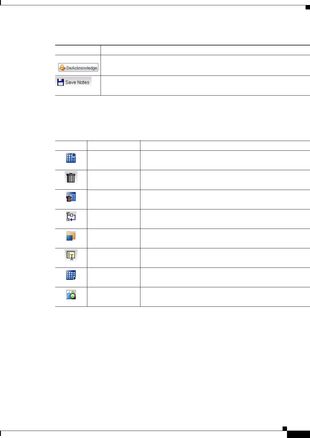
REVIEW DRAFT—CISCO CONFIDENTIAL
A-19
Cisco Prime Network 4.0 User Guide
OL-29343-01
Appendix A Icon and Button Reference Badges
Report Manager Buttons
Badges
Badges are small icons that appear with other network elements, such as element icons or links.
The following topics describe the badges used by Prime Network Vision and Prime Network Events:
• VNE Communication State Badges, page A-20
• VNE Investigation State Badges, page A-20
• Network Element Technology-Related Badges, page A-21
Clicking on this ticket will deacknowledge a ticket.
Saves the notes for the selected ticket.
This button is enabled only when text is entered in the Notes field of the Notes tab.
Table A-14 Report Manager Buttons
Icon Name Description
Define Report of
This Type Enables you to define a report of this type that is suited specifically
to your environment.
Delete Deletes one or more folders that you created.
Delete Report Deletes the selected report.
Move Moves one or more folders or reports that you created.
New Folder Creates a new folder
Rename Renames a folder that you created.
Run Generates the selected report
View Displays the selected report in HTML format.
Table A-13 Ticket Properties Window Buttons (continued)
Icon Description

REVIEW DRAFT—CISCO CONFIDENTIAL
A-20
Cisco Prime Network 4.0 User Guide OL-29343-01
Appendix A Icon and Button Reference
Badges
VNE Communication State Badges
VNE Investigation State Badges
Table A-15 VNE Communication State Badges
Badge State Name Description
None Agent Not Loaded The VNE is not responding to the gateway because it was stopped, or it was just
created. This communication state is the equivalent of the Defined Not Started
investigation state.
VNE/Agent Unreachable The VNE is not responding to the gateway. This can happen if the unit or AVM is
overutilized, the connection between the gateway and unit or AVM was lost, or the
VNE is not responding in a timely fashion. (A VNE in this state does not mean the
device is down; it might still be processing network traffic.)
None Connecting The VNE is starting and the initial connection has not yet been made to the device.
This is a momentary state. Because the investigation state decorator (the hourglass)
will already be displayed, a special GUI decorator is not required.
Device Partially Reachable The element is not fully reachable because at least one protocol is not operational.
Device Unreachable The connection between the VNE and the device id down because all of the protocols
are down (though the device might be sending traps or syslogs).
None Tracking Disabled The reachability detection process is not enabled for any of the protocols used by the
VNE. The VNE will not perform reachability tests nor will Prime Network generate
reachability-related events. In some cases this is desirable; for example, tracking for
Cloud VNEs should be disabled because Cloud VNEs represent unmanaged network
segments.
Table A-16 VNE Investigation State Badges
Badge State Name Description
None Defined Not Started A new VNE was created (and is starting); or an existing VNE was stopped. In this
state, the VNE is managed and is validating support for the device type. (This
investigation state is the equivalent of the Agent Not Loaded communication state.)
A VNE remains in this state until it is started (or restarted) by a user.
Unsupported The device type is either not supported by Prime Network or is misconfigured (it is
using the wrong scheme, or is using reduced polling but the device does not support
it).
To extend Prime Network functionality so that it recognizes unsupported devices, use
the VNE Customization Builder. See the Cisco Prime Network 4.0 Customization
Guide.
Discovering The VNE is building the model of the device (the device type was found and is
supported by Prime Network). A VNE remains in this state until all device commands
are successfully executed at least once, or until there is a discovery timeout.

REVIEW DRAFT—CISCO CONFIDENTIAL
A-21
Cisco Prime Network 4.0 User Guide
OL-29343-01
Appendix A Icon and Button Reference Badges
Network Element Technology-Related Badges
None Operational The VNE has a stable model of the device. Modeling may not be fully complete, but
there is enough information to monitor the device and make its data available to other
applications, such as activation scripts. A VNE remains in this state unless it is
stopped or moved to the maintenance state, or there are device errors.
Currently Unsynchronized The VNE model is inconsistent with the device. This can be due to a variety of
reasons; for a list of these reasons along with troubleshooting tips, see the topic on
troubleshooting VNE investigation state issues in the Cisco Prime Network 4.0
Administrator Guide.
Maintenance VNE polling was suspended because it was manually moved to this state (by
right-clicking the VNE and choosing Actions > Maintenance). The VNE remains in
this state until it is manually restarted. A VNE in the maintenance state has the
following characteristics:
• Does not poll the device, but handles syslogs and traps.
• Maintains the status of any existing links.
• Does not fail on VNE reachability requests.
• Handles events for correlation flow issues. It does not initiate new service alarms,
but does receive events from adjacent VNEs, such as in the case of a Link Down
alarm.
The VNE is moved to the Stopped state if: it is VNE is moved, the parent AVM is
moved or restarted, the parent unit switches to a standby unit, or the gateway is
restarted.
Partially Discovered The VNE model is inconsistent with the device because a required device command
failed, even after repeated retries. A common cause of this state is that the device
contains an unsupported module. To extend Prime Network functionality so that it
recognizes unsupported modules, use the VNE Customization Builder. See the
Cisco Prime Network 4.0 Customization Guide.
Shutting Down The VNE has been stopped or deleted by the user, and the VNE is terminating its
connection to the device.
None Stopped The VNE process has terminated; it will immediately move to Defined Not Started.
Table A-17 Network Element Technology-Related Badges
Icon Description
Access gateway
Blocking
Clock service
Table A-16 VNE Investigation State Badges (continued)
Badge State Name Description
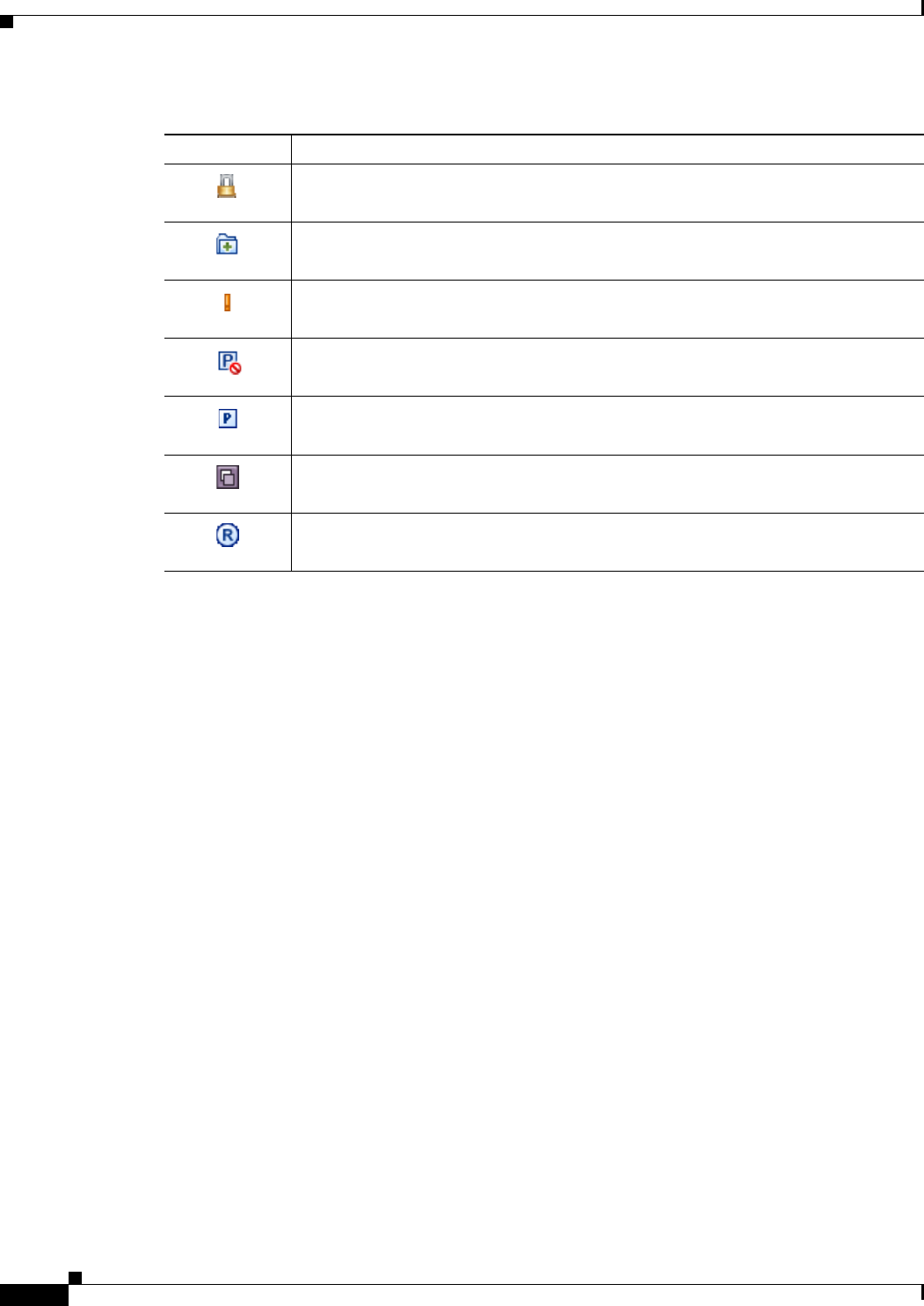
REVIEW DRAFT—CISCO CONFIDENTIAL
A-22
Cisco Prime Network 4.0 User Guide OL-29343-01
Appendix A Icon and Button Reference
Badges
Alarm and Ticket Badges
See Severity Icons, page A-13 for information about the icons used for alarm and ticket badges.
Associated LSP is in lockout state
Multiple links
Reconciliation
REP blocking primary
REP primary
Redundancy service
STP root
Table A-17 Network Element Technology-Related Badges (continued)
Icon Description

GL-1
Cisco Prime Network 4.0 User Guide
OL-29343-01
REVIEW
DRAFT
—
CISCO
CONFIDENTIAL
GLOSSARY
A
AAA AAA refers to Authentication, Authorization, and Accounting, which is a security architecture for
distributed systems that determines the access given to users for specific services and the amount of
resources they have used.
aggregation A user-defined collection of network elements. For example, an aggregation can contain devices,
links, VPNs, and other aggregations.
alarm Sequence of event notifications that share the same source, cause, or fault. For example, if a single
port goes up and then down, these two events in a related sequence may result in a single alarm. An
alarm is stateful and is opened when a fault is first detected. Event notifications may be added to the
alarm, and it is archived when it is fixed.
association A relationship between the following types of network elements: a logical (protocol-oriented)
network element and a physical network element; a logical network element and another logical
network element; or an existing association and anything else. An example for a VPN would be an
association between the physical IP interface and Virtual Routing and Forwarding (VRF) table,
which is the associated routing table. An association is not considered a topological link.
B
BFD Bidirectional Forwarding Detection (BFD) is used to detect communication failures between two
elements, or endpoints, that are connected by a link, such as a virtual circuit, tunnel, or LSP.
BNG Broadband Network Gateway (BNG) provides capabilities that help to improve the service provider's
ability to manage the subscriber's services, and simplify overall network operations.
business element Construction or organization of certain network elements and their properties into a logical entity, to
provide the ability to track them in a way that makes sense from a business perspective. A virtual
private network (VPN) is a business element, which represents a set of interconnected sites that form
a single network over a public network. Prime Network organizes the business elements in a way that
creates a containment hierarchy that reflects the VPN structure.
business tag A string that is meaningful to the business, and that can be used to label a component of a network
element for use in Prime Network screens and reports. There are three types of business tags:
subscriber, provider, and label. Business tags are stored in the Prime Network gateway database.

REVIEW DRAFT—CISCO CONFIDENTIAL
Glossary
GL-2
Cisco Prime Network 4.0 User Guide OL-29343-01
C
carrier grade NAT A large-scale Network Address Translation (NAT) that provides translation of millions of private
IPv4 addresses to public IPv4 addresses.
CCM Change and Configuration Management provides tools that allow you to manage the software and
device configuration changes that are made to devices in your network.
D
data center A centralized repository, either physical or virtual for the storage, management, dissemination of data
and information organized around a particular manner. In other words, it is a facility used to house
computer systems and associated components, such as telecommunications and storage systems.
DHCP Dynamic Host Configuration Protocol is used to automate host configuration by assigning IP
addresses, delegating prefixes (in IPv6), and providing extensive configuration information to
network computers.
dynamic links The physical and logical links that exist between elements in the network. These links are discovered
by Prime Network using various protocols (such as STP, CDP, and LLDP).
dynamic templates Used to group configuration items, which are later applied to a group of subscribers. This template is
globally configured through the command line interface (CLI).
E
ePDG Secures the data transmission with a UE connected to the EPC over an untrusted non-3GPP access.
For this purpose, the ePDG acts as a termination node of IPsec tunnels established with the UE.
event In the context of network management, a discrete activity that occurred at a specific point in time.
E-LMI Ethernet Local Management Interface (E-LMI) is a protocol that operates between the customer edge
(CE) network element and the provider edge (PE) network element. Ethernet LMI is a protocol
between the CE network element and the provider edge (PE) network element.
F
FabricPath An innovation in Cisco NX-OS software that brings the stability and scalability of routing to Layer
2. It provides a foundation to build a scalable fabric—a network that itself looks like a single virtual
switch from the perspective of its users.
Foreign Agent A router on a mobile node’s visited network that provides routing services to the mobile node. The
FA acts as a mediator between the mobile node and it’s home agent (HA).

REVIEW DRAFT—CISCO CONFIDENTIAL
Glossary
GL-3
Cisco Prime Network 4.0 User Guide
OL-29343-01
G
GRE Generic routing encapsulation (GRE) is a tunneling protocol, originated by Cisco Systems and
standardized in RFC 2784. GRE encapsulates a variety of network layer packets inside IP tunneling
packets, creating a virtual point-to-point link to devices at remote points over an IP network.
H
Home Agent A router on a mobile node’s home network which tunnels datagrams for delivery to the mobile node
when it is away from home. It maintains current location (IP address) information for the mobile node.
It is used with one or more foreign agents.
HSGW HRPD Serving Gateway, a component in the evolved High Rate Packet Data (eHRPD) mobile
network. It terminates the eHRPD access network interface from the Evolved Access Network (eAN)
or Evolved Packet Core Function (ePCF) and routes UE-originated or terminated packet data traffic.
HSRP Hot Standby Router Protocol (HSRP) is a protocol that provides backup to a router in case of failure.
Using HSRP, several routers are connected to the same Ethernet network segment and work together
to present the appearance of a single virtual router.
H-VPLS Partitions the network into several edge domains that are interconnected using an MPLS core. The
edge devices learn only of their local N-PE devices and therefore do not need large routing table
support.
I
IP Multicast A bandwidth-conserving technology that reduces traffic by simultaneously delivering a single stream
of information to thousands of corporate recipients and homes.
IP Pool An IP pool is a sequential range of IP addresses within a certain network. IP addresses can be assigned
dynamically from a single pool or from a group of pools for services running on a network element.
IPSec The Internet Protocol Security suite that interacts with one another to provide secure private
communications across IP networks.
IS-IS Intermediate System-to-Intermediate System (IS-IS) protocol is a routing protocol developed by the
ISO. It is a link-state protocol where IS routers exchange routing information based on a single metric
to determine network topology.
L
LAC Layer 2 Tunnel Access Concentrator, which allows users and telecommuters to connect to their
corporate intranets or extranets using L2TP. In other words, it forwards packets to and from the LNS
and a remote system.
link A physical or logical connection between two devices in the network, a device and an aggregation, or
two aggregations.

REVIEW DRAFT—CISCO CONFIDENTIAL
Glossary
GL-4
Cisco Prime Network 4.0 User Guide OL-29343-01
LMA Local Mobility Anchor is the home agent for a mobile node in a Proxy Mobile IPv6 (PMIPv6)
domain. It is the topological anchor point for mobile node home network prefixes and manages the
binding state of an mobile node.
logical link An association between two network elements (based on a chain of physical links between the
elements); for example, a tunnel.
M
managed element A network element that is managed by Prime Network; for example, a device, cloud, or Internet
Control Message Protocol (ICMP) VNE.
MLPPP Multilink PPP is a protocol that connects multiple links between two systems as needed to provide
bandwidth when needed. MLPPP packets are fragmented, and the fragments are sent at the same time
over multiple point-to-point links to the same remote address.
MME Mobility Management Entity is the key control-node for an LTE access network, which works in
conjunction with NodeB(eNodeB), Serving Gateway, or the LTE/SAW core network. It is responsible
for initiating paging and authentication of mobile devices.
N
network clock service The means by which a clock signal is generated or derived and distributed through a network and its
individual nodes for the purpose of ensuring synchronized network operation.
network element Any physical component or device in the network that can be managed through an IP address.
P
PDSN Packet Data Serving Node is a component of the Code Division Multiple Access (CDMA) 2000
mobile network. It acts as a connection point between the Radio Access Network (RAN) and IP
Network.
physical link A link between physical network objects; for example, a connection between two physical ports.
provider The party providing a service.
pseudowire An emulation of a point-to-point connection over a packet-switching network (PSN), which operates
over a uniform packet-based access/aggregation networ
pseudowire headend A technology that allows termination of access or aggregation pseduowires into an L2 or L3 domain.
It replaces a 2-node solution with a 1-node solution.

REVIEW DRAFT—CISCO CONFIDENTIAL
Glossary
GL-5
Cisco Prime Network 4.0 User Guide
OL-29343-01
Q
QoS Quality of services is the technique of prioritizing traffic flows and specifying preferences for
forwarding packets with higher priority.
S
SAN A storage area network (SAN) is a dedicated network that provides access to consolidated, block level
data storage.
SBC Session Border Controllers control and manage real-time multimedia traffic flows between IP
network borders, handling signaling, and media.
SCTP Stream Control Transmission Protocol is a message oriented, reliable transport protocol with direct
support for multihoming that runs on top of Internet Protocol (IPv4/IPv6).
SGSN Serving GPRS Support Node is a very important component of the GPRS network. It is responsible
for handling the delivery of data from and to the mobile nodes within its geographical service area,
such as packet routing and transfer, mobility management, and authentication of users
static links Links that are created at the VNE level but are not updated. These links do not perform any
configuration or provisioning on a device or in the network.
subscriber The party receiving a service.
subscriber access
points The access interfaces that are named based on the parent interface.
T
ticket Object that represents an attention-worthy root alarm whose type is marked in the registry as
“ticketable.” A ticket has the same type as the root alarm it represents, and it has a status, which
represents the entire correlation tree. A ticket can be acknowledged by the user. Both Prime Network
Vision and Cisco Prime Network Events display tickets and allow you to navigate down to view the
consequent alarm hierarchy. From an operator’s point of view, a fault is always represented by a
complete ticket. Operations such as Acknowledge or Remove are applied to the whole ticket.
U
unassociated bridges Switching Entities that do not belong to a flow domain, such as a network VLAN, a VPLS instance,
or a network pseudowire.
V
virtual cloud or
unmanaged network Network, or part of a network, that is not managed by Prime Network. An unmanaged network is often
represented in network diagrams by a cloud symbol or image.

REVIEW DRAFT—CISCO CONFIDENTIAL
Glossary
GL-6
Cisco Prime Network 4.0 User Guide OL-29343-01
virtualization A concept of creating a virtual version of any resource, such as hardware platform, operating system,
storage device, or network resources
VLAN Virtual local-area network (LAN). Group of devices on one or more LANs that are configured (using
management software) so that they can communicate as if they were attached to the same wire, when
in fact they are located on a number of different LAN segments. Because VLANs are based on logical
instead of physical connections, they are extremely flexible.
VPC Virtual Port Channel (vPC) allows links that are physically connected to two different Cisco Nexus
7000 or Cisco Nexus 5000 series network elements to appear as a single port channel by a third device.
VPLS Virtual Private LAN Service is a Layer 2 VPN technology that provides Ethernet-based
multipoint-to-multipoint communication over MPLS networks. VPLS allows geographically dispersed
sites to share an Ethernet broadcast domain by connecting sites through pseudowires.
VPN Virtual Private Network. Enables IP traffic to travel securely over a public TCP/IP network by
encrypting all traffic from one network to another. A VPN uses tunneling to encrypt all information at
the IP level.
VRRP Virtual Router Redundancy Protocol is a non-proprietary redundancy protocol that is designed to
increase the availability of the static default gateway servicing hosts on the same subnet. This
increased reliability is achieved by advertising a virtual router (a representation of master and backup
routers acting as a group) as a default gateway to the hosts instead of one physical router.
VSAN A virtual storage area network is a collection of ports from a set of connected Fibre Channel switches,
that form a virtual fabric. Ports within a single switch can be partitioned into multiple VSANs, despite
sharing hardware resources.
VSG Cisco Virtual Security Gateway is a virtual firewall appliance that provides trusted access to virtual
data center and cloud environments. It enables a broad set of multi tenant workloads that have varied
security profiles to share a common compute infrastructure in a virtual data center private cloud or in
a public cloud.
Y
Y.1731 Y.1731 is an ITU-T recommendation that provides mechanisms for service-level Operation,
Administration, and Maintenance (OAM) functionality in Ethernet networks.

IN-1
Cisco Prime Network 4.0 User Guide
OL-29343-01
INDEX
Numerics
3GPP inventory retrieval 25-109
6rd
add 6rd forwarding (command) 13-6
tunnels, viewing properties 18-46
6VPE
and IPv6 17-1
IPv6 VPN over MPLS 17-1
A
A10/A11 configurations (HSGW) 25-58
AAA 22-9
APN and 25-18
commands. See AAA commands
diameter protocol 22-1
dynamic protocol authorization profile 22-3
foreign agent and 25-73, 25-76
groups
charging configuration 22-10
charging trigger configuration 22-11
configuration 22-5
diameter configuration 22-6
profile 22-2
RADIUS accounting configuration 22-7
RADIUS authentication configuration 22-9
RADIUS configuration 22-7
home agent and 25-69
HSGW and 25-54
LAC configuration and 25-51
overview 22-1
PDSN and 25-92
RADIUS global configuration 22-4
RADIUS protocol 22-1
AAA commands
create AAA group 25-138
create diameter accounting server 22-12
create diameter authentication server 22-12
delete AAA group 22-12
modify AAA group 22-12
access gateway
badge 3-8, A-21
viewing properties 12-19
access list commands
create route access lists 25-138
remove access list 1-6
show route access lists 25-138
See also route maps
accumulating affected parties
in an alarm 9-18
in the correlation tree 9-19
acknowledging tickets 9-15
ACS
bandwidth policies 25-135
charging action
rule base, viewing 25-133
viewing properties 25-128
commands. See ACS commands
content filtering
overview 25-122
viewing categories 25-125
content services steering 25-121
create active charging service (command) 25-138
credit control properties, viewing 25-125
fair usage properties 25-136

Index
IN-2
Cisco Prime Network 4.0 User Guide OL-29343-01
overview 25-121
protocol analyzer 25-121
rule base
for charging action, viewing 25-133
overview 25-122
rule definition groups
commands. See ACS commands
viewing 25-132
rule definitions
overview 25-121
viewing 25-131
viewing 25-123
ACS commands
create access ruledef 25-136
create charging action 25-136
create group of ruledefs 25-136
create host pool 25-136
create rulebase 25-136
create ruledef 25-136
delete access ruledef 25-136
delete active charging service 25-136
delete charging action 25-136
delete host pool 25-136
modify active charging service 25-136
modify charging action 25-136
modify host pool 25-136
rule definition groups
delete group of ruledefs 25-133
show group of ruledefs 25-133
show access ruledef 25-136
show charging action 25-136
Activation
cloning an activation 3-37
deleting activations 3-37
menu 2-29
rolling back activations 3-36
running activations 3-35
searching for activations 3-36
window 3-35
wizards 3-35
activation script, launching 2-39
Active Charging Service. See ACS
ADSL2+
device inventory, viewing 28-4
DSL cable bonding group 28-5
n-to-one access profile 28-8
one-to-one access profile 28-8, 28-10
overview 28-2
TLS access profile 28-8, 28-11
user roles required 28-1
viewing properties 28-2
XDSL traffic descriptors 28-2
Advanced tab (Events GUI) 8-13, 9-13
affected elements 9-13
affected parties 9-17
accumulating 9-18, 9-19
Affected Parties tab (tickets) 9-11
calculating 9-18
affected severities 9-13, 9-19
Agent Not Loaded (VNE communication state) 2-21
Agent Unreachable, VNE communication state 2-21
aggregations 5-16
adding elements to 5-18
creating 5-16
disaggregating 5-19
right-click options 2-36
thumbnails 5-16
working with thumbnail views 5-15
alarms
alarm count in ticket 9-6
alarm count in tickets 9-13
badges A-22
customizing 2-40
disabling on a port 3-26
severities 9-17
APN
commands. See APN commands
overview 25-13

Index
IN-3
Cisco Prime Network 4.0 User Guide
OL-29343-01
profiles 25-115, 25-119
remap tables 25-113
view properties 25-14, 25-18
APN commands
create APN 25-138
create QoS to DSCP mapping 25-22
create virtual APN 25-22
delete APN 25-22
modify APN 25-22
show APN 25-138
application, launching external 2-34, 2-38
applying overlays
VPLS instance 12-80
VPN 18-24
APS commands
create APS 20-59
modify APS 20-59
ARP table 18-34
associated VLANs
adding 12-55
tag manipulations 12-55
viewing
mapping properties 12-57
service links 12-57
working with 12-55
ATM cross-connects
in logical and physical inventory 20-6
overview 20-6
viewing 20-6
audience, intended xxiii
audio options, customizing 2-40
Audit tab (events) 8-4, 8-13
B
background images for maps 5-12
badges A-19
access gateway 3-8, A-21
alarms 2-19, A-22
blocking 3-8, A-21
clock service 3-8, A-21
for elements and links 3-8
lock 3-8, 18-6, A-22
management states A-19
multiple links 3-8, A-22
reconciliation 3-9, 12-50, A-22
redundancy service 3-9, A-22
REP primary 3-9, A-22
REP primary blocking 3-9, A-22
STP root 3-9, A-22
technology related A-21
tickets A-22
VNE communication states A-20
VNE investigation states A-20
VNE management states 2-19
BBA (Broadband Access) groups 24-3
BFD
commands. See MPLS-TP commands
viewing BFD session properties 18-47
viewing MPLS-TP BFD session properties 18-49
BGP
commands
create BGP address family 18-59
create BGP neighbor 18-59
create BGP router 18-59
delete BGP address family 18-59
delete BGP neighbor 18-59
delete BGP router 18-59
modify BGP address family 18-59
modify BGP neighbor 18-59
modify BGP router 18-59
viewing inventory details 18-45
Bidirectional Forwarding Detection. See BFD
blocking badge 3-8, A-21
BNG
Broadband Access Groups (BBG) 24-3
configuration templates 24-9
IP subscriber 24-9

Index
IN-4
Cisco Prime Network 4.0 User Guide OL-29343-01
overview 24-9
PPP 24-12
service 24-9
viewing 24-9
DHCP service profile 24-7
overview 24-1
QoS profile 24-16
service groups 24-13
service policies 24-13
subscriber access points
diagnosing 24-6
viewing 24-5
user role required 24-2
bridges
unassociated 12-73
viewing properties for VLANs 12-70
Broadband Access (BBA) groups 24-3
Broadband Network Gateway. See BNG
bundle ethernet, configuring (configure bundle ethernet
command) 18-61
business elements 7-1
defined 7-1
deleting 7-7
icons 2-11, A-4
renaming 7-7
user roles required 7-1
See also business tags
business tags 7-1
attaching and detaching 7-3
Chinese characters 7-2
defined 7-1
searching for 7-4
user roles required 7-1
See also business elements
buttons (GUI)
in Prime Network Events A-18
in Prime Network Vision A-14
for filtering links A-17
in tables A-17
in Report Manager A-19
in tickets window A-18
C
cable
CMTS 27-1
DOCSIS 27-1
DSL 27-1
fiber node 27-10
MAC domain 27-6
narrowband channels 27-8
overview 27-1
QAM domain 27-5
user roles required 27-2
wideband channels 27-8
Carrier Ethernet services
types 12-1
user roles required 12-2
Carrier Grade NAT
commands
add 6rd forwarding 13-6
add CGNAT or 6rd forwarding 13-6
add NAT 64 forwarding 13-6
add static port forwarding 13-6
create CGNAT instance 13-6
show pool utilization 13-5, 13-6
static port forwarding 13-6
monitoring 13-1
user roles required 13-2
viewing properties
logical inventory 13-2
physical inventory 13-5
Carrier Supporting Carrier (CSC) path traces 11-31
CCM
Compliance Audit. See Compliance Audit
Configuration Audit. See Configuration Audit
device groups. See device groups (CCM)
global settings 4-61

Index
IN-5
Cisco Prime Network 4.0 User Guide
OL-29343-01
GUI 4-1
jobs 4-68
overview 1-3, 4-1
processes, check 4-68
setup tasks
Configuration Management 4-5
device groups 4-9
devices 4-4
Prime Network 4-3
user roles 4-69
CDP. See Cisco Discovery Protocol
CESoPSN, viewing properties 20-3
CFM
commands. See CFM commands
description
maintenance domains 15-3
maintenance endpoints (MEPs) 15-3
maintenance intermediate points (MIPS) 15-3
overview 15-3
viewing properties for
maintenance associations 15-8
maintenance domains 15-5, 15-7
MEPs 15-8
MIPs 15-6
remote MEPs 15-10
CFM commands
configure CFM continuity check 15-18
configure CFM global parameters 15-18
configure CFM maintenance domain 15-18
configure CFM MEP 15-18
configure CFM MIP 15-18
configure CFM service ID 15-18
enable CFM continuity check 15-18
enable CFM SNMP server traps 15-18
CG-NAT. See Carrier Grade NAT
Change and Configuration Management. See CCM
change logs (Configuration Management) 4-69
channelization and TDM. See TDM and channelization
chassis, devices with multi 5-19
Chinese characters in business tags 7-2
Circuit Emulation Services over PSN. See CESoPSN
Cisco Discovery Protocol (CDP) properties
in logical inventory 12-6
in physical inventory 12-8
viewing 12-6
clearing and removing tickets 9-16
clock
commands (MToP)
create ESMC global 20-55
create ESMC interface 20-55
create PTP clock global 20-55
create PTP clock port 20-55
create PTP interface 20-55
create syncE global 20-55
create syncE interface 20-55
delete PTP clock global 20-55
delete PTP clock port 20-55
disable ESMC interface 20-55
modify ESMC global 20-55
modify ESMC interface 20-55
modify PTP clock global 20-55
modify PTP clock port 20-55
modify PTP interfaces 20-55
modify syncE global 20-55
modify syncE interface 20-55
show PTP clock global 20-55
recovery, pseudowire properties 20-44
service
badge 3-8, A-21
properties 20-35
CM. See Configuration Management
CMTS 27-1
Command Builder 2-39
Command Manager 2-39
commands
AAA
create diameter accounting service 22-12
create diameter authentication server 22-12

Index
IN-6
Cisco Prime Network 4.0 User Guide OL-29343-01
delete AAA group 22-12
modify AAA group 22-12
ACS. See ACS commands
cable
DEPI and L2TP. See DEPI and L2TP commands
interfaces. See interfaces commands
ports. See ports commands
QAM. See QAM configurations
show downstream 27-12
show upstream 27-12
Carrier Ethernet services
IS-IS. See IS-IS commands
mLACP. See mLACP commands
pseudowire. See pseudowire commands
REP. See REP commands
VLANs. See VLAN commands
CG NAT. See CG-NAT commands
configuration files
from FTP/TFTP 1-10
show running config 1-10
show startup config 1-10
to FTP/TFTP 1-10
write memory 1-10
data center. See data center commands
delete context 25-138
device setup
access lists. See access list commands
DNS. See DNS commands
host name. See host name commands
interfaces. See interfaces commands
NTP. See NTP commands
ports. See ports commands
RADIUS. See RADIUS commands
SNMP configuration. See SNMP configuration
SNMP traps. See SNMP traps
TACACS. See TACACS commands
DHCP. See DHCP commands
DWDM. See DWDM commands
Ethernet OAM
CFM. See CFM commands
E-LMI. See E-LMI commands
L-OAM. See L-OAM commands
FabricPath (data center). See FabricPath commands
GPRS/UMTS
APN. See APN commands
eGTP. See eGTP commands
GGSN. See GGSN commands
GTPP. See GTPP commands
GTPU. See GTPU commands
IP pool
delete IP pool 23-3
modify IP pool 23-3
licenses
modify licenses 25-138
show licenses 25-138
LTE
ePDG. See ePDG commands
foreign agent. See foreign agent commands
HSGW. See HSGW commands
MME. See MME commands
PDSN. See PDSN commands
P-GW. See P-GW commands
SAE-GW. See SAE-GW commands
S-GW. See S-GW commands
modify license 25-138
MPLS services
BGP. See BGP commands
bundle ethernet. See bundle ethernet commands
IP interface. See IP interface (MPLS) commands
MPLS. See MPLS commands
MPLS-TE. See MPLS-TE commands
MPLS-TP commands. See MPLS-TP commands
RSVP. See RSVP commands
VRF. See VRF commands
VRRP. See VRRP commands
MToP services
APS. See APS
clock. See clock commands (MToP)

Index
IN-7
Cisco Prime Network 4.0 User Guide
OL-29343-01
SONET. See SONET commands
TDM and channelization. See TDM and
channelization commands
PDP. See PDP commands
ping. See ping commands
route maps. See route maps commands
SBC. See SBC commands
show users (Telnet sessions) 1-10
subscriber. See subscriber commands
syslog host logging 1-9
trace route. See trace route commands
VLAN commands. See VLAN commands
vPC (data center). See data center commands
Y.1731. See Y.1731 commands
Y.1731 IPSLA. See Y.1731 IPSLA commands
communication status, for VNEs 3-17
Compliance Audit
audit, run 4-58
compliance policy 4-52
Configuration Audit and 4-2
overview 4-2, 4-50, 4-52
policy profile 4-57
results, view 4-59
user roles required 4-51
violations 4-59
See also CCM
Configuration Audit 4-45
Compliance Audit and 4-2
jobs, manage 4-48
policies
create 4-46
manage 4-47
policy example 4-45
results, view 4-48
schedule 4-47
user roles required 4-69
See also CCM
Configuration Management
archive 4-12
backing up files to archive 4-18
change logs 4-25
cleaning up archive 4-25
comparing files 4-14
exported files per device families 4-66
exporting files 4-16
global settings 4-61
labelling files 4-13
overview 4-2
restoring file from archive to devices 4-22
setup tasks 4-5
synchronizing files 4-17
user roles required 4-69
See also CCM
configuration scripts, launching 2-39
Connecting, VNE communication state 2-21
Connectivity Fault Management. See CFM
Control Channel (CC), viewing information for
pseudowire endpoint 12-95
conventions, used in this document xxvi
Correlation tab (tickets) 9-13
CPU usage graph, opening 5-27
crypto template (ePDG) 25-84
CSR 1000v 26-29
Currently Unsynchronized, VNE investigation state 2-22
D
data center
commands. See data center commands
FabricPath. See FabricPath
overview 26-1
user roles required 26-2
virtualization. See virtualization
vPC. See vPC
data center commands
FabricPath
show FabricPath conflict 26-10
show MAC address table learning mode 26-10

Index
IN-8
Cisco Prime Network 4.0 User Guide OL-29343-01
vPC
show port channel capacity 26-7
show vPC 26-7
show vPC consistency parameter 26-7
Defined Not Started, VNE investigation state 2-21
Dense Wavelength Division Multiplexing. See DWDM
DEPI and L2TP commands 27-14
create DEPI class 27-14
create DEPI tunnel 27-14
create L2TP class 27-14
delete DEPI class 27-14
delete DEPI tunnel 27-14
delete L2TP class 27-14
modify DEPI tunnel 27-14
modify L2TP class 27-14
show cable DEPI session 27-14
show DEPI session 27-14
show DEPI tunnel 27-14
show L2TP class 27-14
Details tab (Events GUI) 8-11, 8-15, 9-10
device configuration files
commands
copy from FTP/TFTP 1-10
copy to FTP/TFTP 1-10
See also Configuration Management
device groups (CCM)
setup tasks 4-9
user roles required 4-69
See also CCM
device image files. See Image Management
Device Partially Reachable, VNE communication
state 2-21
devices
aggregations 5-16
configuration files. See device configuration files
CPU usage, checking 5-27
icons 2-9, A-2
in maps 5-16
multi-chassis 5-19
pinging 5-28
right-click menu 2-32
satellite 3-22, 4-41
setting up 1-4
severity indicator 2-18
software image files. See Image Management
status indicators 2-17
Telnet to a device 5-28
traceroute from device (command) 1-9
viewing
operating system information 3-31
properties 3-6
Device Unreachable, VNE communication state 2-21
DHCP
commands
create DHCP 25-138
delete DHCP 25-138
modify DHCP 25-138
show DHCP 25-138
show DHCP binding (subscriber access
points) 24-6
service profile 24-7
Discovering, VNE investigation state 2-22
discovery
EFD 12-45
EVC multiplex services 12-106
MPLS-TP tunnels 18-5
VLAN 12-45
DNS commands
add DNS server 1-5
add DNS server command 1-5
create proxy DNS 25-138
delete proxy DNS 25-138
modify proxy DNS 25-138
remove DNS server 1-5
remove DNS server command 1-5
document
audience xxiii
conventions xxvi

Index
IN-9
Cisco Prime Network 4.0 User Guide
OL-29343-01
organization xxiv
related documentation xxvii
downstream rates, show (cable) 27-12
DSL
ADSL2. SeeADSL2
cable technologies and 27-1
VDSL2. See VDSL2
duplication count (tickets) 9-13
DWDM
commands. See DWDM commands
user roles required 14-1
viewing
alert and alarm counters 14-9
G.709 properties 14-5
ODU alarm properties 14-8
ODU alert properties 14-9
OTU alarm properties 14-8
OTU alert properties 14-9
performance monitoring configuration 14-11
properties 14-3
DWDM commands
clear counters 14-15
configure channel 14-15
configure FEC mode 14-15
configure G.709 ODU 14-15
configure G.709 OTU 14-15
configure G.709 TTI 14-15
configure G.709 wrapper 14-15
configure laser state 14-15
configure loopback 14-15
configure PM FEC data 14-15
configure PM optics data 14-15
configure PM OTN data 14-15
configure Rx LOS threshold 14-15
configure transmit power 14-15
show controller data 14-15
show device log 14-15
show IM trace details 14-15
show PM history data 14-15
show RTPM counters 14-15
show RTPM threshold 14-15
show wavelength map 14-15
Dynamic Host Configuration Protocol. See DHCP
E
EAP profile (ePDG) 25-87
EFD discovery 12-45
EFP
cross-connects 12-75
adding 12-76
viewing properties 12-76
overview 12-47
severity and ticket badges 12-38
egress adjacents, VRF 18-31
eGTP
commands
create EGTP 25-138
delete eGTP 25-31
modify eGTP 25-31
show EGTP 25-138
overview 25-30
view properties 25-31
element icons, and information displayed 3-3
E-LMI. See Ethernet LMI
ePDG
commands
create ePDG service 25-92
delete ePDG service 25-92
modify ePDG service 25-92
show ePDG service 25-92
IPSec and 25-84
overview 25-83
security 25-84
crypto template 25-84
EAP profile 25-87
transform set details 25-88
viewing configuration details 25-90

Index
IN-10
Cisco Prime Network 4.0 User Guide OL-29343-01
ESM configuration (MME) 25-151
Ethernet flow domains
listing all 2-5
renaming 12-42
viewing properties of 12-42
Ethernet flow point (EFP), viewing properties 12-33
Ethernet LAGs, viewing 12-23
Ethernet links, and configured LSPs 18-11
Ethernet LMI
commands. See Ethernet LMI commands
Device EVC Properties window 15-12
enable 15-18, 15-20
EVC, configure 15-18, 15-20
overview 15-10
service instance, configure 15-18, 15-20
UNI, configure 15-18, 15-20
viewing properties
for device EVCs 15-11
for physical interfaces 15-12
for UNI interfaces 15-13
in logical inventory 15-11
Ethernet LMI commands
configure multipoint to multipoint or point to point
EVC 15-20
configure service instance VLAN ID on
interface 15-20
configure UNI in an interface 15-20
enable global E-LMI 15-20
enable on interface 15-20
Ethernet Local Management Interface. See Ethernet LMI
Ethernet OAM
overview 15-2
user roles required 15-1
Ethernet Operations, Administration, and Maintenance.
See Ethernet OAM
Ethernet services
adding overlays 12-108
adding to maps 12-106
viewing properties 12-109
working with 12-106
EVC
E-LMI
configuring 15-20
viewing 15-12
E-LMI, configuring 15-18
L-OAM, configuring 15-21
services
multiplex 12-106
shared switching entities 12-40
viewing properties 12-40
events
Advanced tab 8-13
Audit tab 8-13
customizing GUI 2-40
Details tab 8-11
filtering 8-18, 8-20
Provisioning tab 8-13
refreshing information 8-17
reports. See reports
Security tab 8-13
tabs in Prime Network Events 8-4
tickets. See tickets
Trap tab 8-14
viewing event properties 8-10
exporting event data 8-21
external application, launching 2-34, 2-38
F
FabricPath
commands
show FabricPath conflict 26-10
show MAC address table learning mode 26-10
monitoring 26-10
overview 26-7
viewing configuration 26-9
Fault Database vs. Event Archive Statistics report 10-13
fiber node (cable) 27-10
foreign agent

Index
IN-11
Cisco Prime Network 4.0 User Guide
OL-29343-01
AAA and 25-73, 25-76
advertisement configuration 25-75
authentication 25-76
commands. See foreign agent commands
GRE configuration 25-77
home agent details for 25-78
overview 25-72
proxy mobile 25-79
registration revocation 25-80
viewing 25-72
foreign agent commands
create FA 25-81
create IKE 25-81
create SPI 25-81
delete FA 25-81
delete IKE 25-81
delete SPI 25-81
modify authentication 25-81
modify FA 25-81
modify GRE 25-81
modify HA configuration 25-81
modify IKE 25-81
modify proxy mobile IP 25-81
modify registration revocation 25-81
modify SPI 25-81
show FA 25-81
G
General tab, in inventory window 3-13
GGSN
commands
create GGSN 25-138
create PLMN identifier 25-10
create SGSN 25-10
delete GGSN 25-10
modify GGSN 25-10
overview 25-6
view properties 25-7, 25-8
GMM properties (SGSN) 25-37
GPRS/UMTS network
GGSN. See GGSN
GPRS/UMTS networks
APN. See APN
eGTP. See eGTP
GTPP. See GTPP
GTPU. See GTPU
overview 25-4
SGSN. See SGSN
technologies 25-6
graphical links, reducing number of in maps 2-11
GRE
foreign agent configuration (LTE networks) 25-77
home agent and 25-70
HSGW 25-59
PDSN 25-96
groups
RADIUS keepalive and detect dead server 22-9
GTPP
create GTPP (command) 25-138
overview 25-23
view properties 25-24, 25-25
GTPU
commands
create GTPU 25-138
create GTPU bind IP address 25-12
delete GTPU 25-12
delete GTPU bind IP address 25-12
modify GTPU 25-12
modify GTPU bind IP address 25-12
overview 25-11
view properties 25-11
GTTP
commands
create CGF 25-29
create storage server 25-29
delete CGF 25-29
delete GTPP 25-29

Index
IN-12
Cisco Prime Network 4.0 User Guide OL-29343-01
delete storage server 25-29
modify CGF 25-29
modify GTPP 25-29
modify storage server 25-29
show CGF 25-29
H
History tab (tickets) 9-11
home agent
AAA and 25-69
commands. See home agent commands
configuration, viewing 25-66
details for foreign agent 25-78
GRE and 25-70
overview 25-65
policy configuration 25-70
registration revocation 25-71
service details 25-67
topology 25-66
home agent commands
create HA Service 25-138
create HA SPI list 25-138
delete HA service 25-138
delete HA SPI list 25-138
modify HA service 25-138
show HA service 25-138
show HA SPI 25-138
host name commands
add host name 1-5
remove host name 1-5
HRPD, create QCI-QOS mapping (command) 25-138
HSGW
A10/A11 configurations 25-58
AAA and 25-54
basic features 25-54
commands. See HSGW commands
GRE parameters 25-59
IP source violation 25-60
MAG 25-62
overview 25-53
QCI mapping details (profile) 25-64
topology 25-54
viewing 25-55
HSGW commands
create HSGW 25-61
create overload policy 25-61
create PLMN entries 25-61
create QCI-QOS mapping 25-138
create SPI 25-61
delete HSGW 25-61
delete overload policy 25-61
delete PLMN entries 25-61
delete SPI 25-61
MAG commands
create MAG 25-64
create profile 25-64
create profile ID QCI mapping 25-64
delete MAG 25-64
delete profile 25-64
delete profile ID QCI mapping 25-64
modify MAG 25-64
modify profile 25-64
show MAG 25-64
modify A10 A11 interfaces 25-61
modify GRE 25-61
modify HSGW 25-61
modify IP source violation 25-61
modify overload policy 25-61
modify PLMN entries 25-61
modify SPI 25-61
show HSGW 25-61
HSRP 12-18
H-VPLS
working with 12-78

Index
IN-13
Cisco Prime Network 4.0 User Guide
OL-29343-01
I
icons
alarm and ticket A-22
badges A-19
business elements 2-11, A-4
information displayed for elements 3-3
links A-10, A-11
logical inventory 3-30, A-7
management states A-19
management states (VNE) 2-19
maps 18-20
network elements 2-10, A-2
physical inventory A-10
Prime Network Events A-13
Prime Network Vision A-1
reconciliation 3-9
reference A-1
REP 12-63
severities A-13
severity, color coding 2-18
sizes 3-3
tickets 2-23
VLAN domains 12-63
VLAN overlays 12-63
See also buttons
Image Management
add images to repository 4-27
Cisco IOS XR 4-37
activate and deactivate packages 4-39
add packages 4-38
commit packages 4-41
considerations 4-37
delete packages 4-39
roll back packages 4-42
satellites 4-40
clean up repository 4-44
clear flash (distributing images) 4-33
delete packages from repository 4-44
distributing images to devices 4-29
global settings 4-66
overview 4-2
repository 4-27
setup tasks 4-7
upgrade analysis and 4-29
user roles required 4-69
See also CCM
IMA group, viewing properties 20-13
impact analysis
accumulating affected parties 9-18
affected severities 9-17
automatic mode 9-17
links and 6-12
proactive mode 9-17
Initializing (VNE management state) 2-19
Inter-Chassis Communication Protocol (ICCP), viewing
properties 12-29
interfaces
commands
add interface configuration
add loopback interface 1-8
configure secondary IP address (MPLS) 18-54
create interface (MPLS) 18-54
create IP interface 27-12
delete interface (MPLS) 18-54
delete IP interfaces 27-12
delete secondary IP address (MPLS) 18-54
disable interfaces
enable interfaces
modify interface (MPLS) 18-54
modify IP interfaces 27-12
remove interface configuration 1-8
show IP interface brief 1-9
show IP route 1-9
update interface configuration 1-8
viewing in physical inventory 3-19
inventory window
content pane 3-13

Index
IN-14
Cisco Prime Network 4.0 User Guide OL-29343-01
device view pane 3-13
device view pane toolbar 3-14
General tab 3-13
logical inventory 3-27
navigation pane 3-12
Network Events tab 3-15
opening 3-9
overview 3-9, 3-11
physical inventory 3-19, 3-21
Ports tab 3-13, 3-23
Provisioning Events tab 3-15
ticket and events pane 3-15
Tickets tab 3-15
IP interface (MPLS) commands
configure secondary IP address 18-54
create interface 18-54
delete interface 18-54
delete secondary IP address 18-54
modify interface 18-54
See also interfaces commands
IPoDWDM. See DWDM
IP pools 23-1
commands
create IP pool 25-138
delete IP pool 23-3
modify IP pool 23-3
show IP pool 25-138
viewing properties 23-1
IPSec and ePDG 25-84
IP SLA
viewing responder service properties 12-112
See also Y.1731
IP source violation
HSGW 25-60
PDSN 25-98
IPv6
addresses
in logical inventory 17-3
in physical inventory 17-4
in inventory 17-3
in Prime Network 17-2
IPv6 VPN over MPLS (6VPE) 17-1
notes, for viewing IPv6 addresses 17-4
support in Prime Network 17-1
user roles required 17-2
viewing IPv6 information 17-2
IS-IS
commands
create ISIS address family 12-121
create ISIS interface 12-121
create ISIS interface address family 12-121
create ISIS router 12-121
delete ISIS address family 12-121
delete ISIS interface 12-121
delete ISIS interface address family 12-121
delete ISIS router 12-121
modify ISIS address family 12-121
modify ISIS interface 12-121
modify ISIS interface address family 12-121
modify ISIS router 12-121
show ISIS configuration 12-121
viewing properties 12-114
L
L2TP (cable). See DEPI and L2TP
label ranges (MPLS-TP)
add label range configuration 18-54
remove label range configuration 18-54
LACs (LTE networks) 25-49
Layer 2 PathTracer (VPN) 11-32
Layer 3 PathTracer (VPN) 11-32
licenses
modify licenses (command) 25-138
show licenses (command) 25-138
link aggregation group. See Ethernet LAGs
Link Layer Discovery Protocol (LLDP), viewing
properties 12-8

Index
IN-15
Cisco Prime Network 4.0 User Guide
OL-29343-01
Link OAM
commands. See Link OAM commands
enabling and disabling 15-21
EVCs, configuring 15-21
overview 15-14
remote loopback, enabling and disabling 15-21
templates, managing 15-21
topology discovery and 15-14
viewing properties in
logical inventory 15-15
physical inventory 15-18
Link OAM commands
assign template on interface 15-21
configure multipoint to multipoint or point to point
EVC 15-21
configure OAM parameters on interface 15-21
disable OAM on interface 15-21
enable E-LMI on interface 15-21
enable OAM on interface 15-21
start remote loopback 15-21
stop remote loopback 15-21
links
adding 6-15
arrowheads 6-5, A-13
bidirectional vs. unidirectional 6-5, A-13
colors 6-5
dashed line 6-4, A-12
dynamic 6-3
exceeding number that can be displayed 2-11
filtering 5-25, 5-27
using collection method 6-17
flickering 6-3
graphical representation 2-11
icons A-10, A-11
impact analysis 6-12
in maps 2-11
links view 6-8
normal vs. wide vs. tunnel 6-5
overview 6-1
properties 6-4
quick view 6-7
reducing number of in maps 2-11
right-click options 2-36
selecting in maps 6-18
solid line 6-4, A-12
static 6-3
tooltips 6-6
tunnels 6-5
types A-11
user roles required 6-1
viewing
between VLAN elements and devices 12-58
in links view 6-8
options 6-17
properties 6-4, 6-10
width 6-5, A-12
LLDP, viewing properties 12-8
LMAs (LTE networks) 25-106
L-OAM. See Link OAM
lock badge 3-8, A-22
logical inventory
branches 3-29
content pane 3-31
content pane tabs 3-31
context 25-138
icons 3-30, A-7
navigation pane 3-29
tabs 3-31
viewing in Prime Network Vision 3-27
window 3-28
loopback
add loopback interface (command) 1-8
remote, enable/disable 15-21
LSEs
inventory details 18-39
viewing 18-39
LSPs
commands. See MPLS-TP commands

Index
IN-16
Cisco Prime Network 4.0 User Guide OL-29343-01
endpoints 18-14
lockout state 18-6
on Ethernet links 18-11
redundancy service properties 18-14
Working and Protected 18-5
LTE networks
ePDG. See ePDG
foreign agent. See foreign agent
home agent. See home agent
HSGW. See HSGW
LACs 25-49
LMAs 25-106
overview 25-40
PDSN. See PDSN
P-GW. See P-GW
QCI-QoS mapping 25-48
SAE-GW. See SAE-GW
S-GW. See S-GW
technologies 25-41
LTE security procedure (MME) 25-152
M
MAC domain (cable) 27-6
MAG (HSGW)
commands. See HSGW commands
viewing configuration 25-62
Maintenance, VNE investigation state 2-22
maintenance domains, in CFM 15-3
management states (VNEs)
badges A-19
icons A-19
overview 2-19
maps 5-1
adding VLANs 12-50
aggregations. See aggregations
applying background images 5-12
closing 5-5
creating 5-6
customizing 2-40
Ethernet services, adding 12-106
filtering links 5-25
link icons A-10
NE icons, zooming in and out 2-9
network elements in 5-16
opening 2-7, 5-5
overlays
callouts 18-25
VPN 18-24
overview 18-18, 18-19
overview window 5-14
PathTracer files 11-26
red border and graphical links 2-11
removing
VLANs 12-52
VPNs 18-23
right-click menu 2-12, 2-32
saving 5-15
selecting views 5-12
severity indicators 2-12
user roles required 5-2
views 2-8
links view 2-15, 2-39
link view 2-16
list view 2-12, 2-37
map view 2-8
VPNs
adding 18-22
overlays 18-24
viewing 18-18
MEPs, in CFM 15-3, 15-18
MIPs, in CFM 15-3, 15-18
mLACP
commands
show channel 12-119
show group 12-119
show LACP internal 12-119
show MPLS LDP 12-119

Index
IN-17
Cisco Prime Network 4.0 User Guide
OL-29343-01
viewing properties 12-29
mLDP
database, viewing 18-42
neighbors, viewing 18-43
overview 18-42
MLPPP
link properties 20-29
MLPPP properties 20-26
MME
commands
create policy accounting 25-138
create QCI-QoS mapping 25-138
delete policy accounting 25-138
modify policy accounting 25-138
configuration details 25-145
EMM configurations 25-150
ESM configuration 25-151
interfaces 25-144
LTE security procedure 25-152
overview 25-143
policy configuration 25-153
S1 interface configuration 25-154
service details 25-146
Mobile Management Entity, See MME
mobile technologies
3GPP inventory retrieval 25-109
ACS 25-121
APN. See APN
GPRS/UMTS. See GRPS/UMTS
LTE. See LTE
operator policies 25-111
user roles required 25-1
Mobile Transport over Packet. See MToP
MP-BGP. See BGP
MPLS
ARP table 18-34
BGP. See BGP
commands. See MPLS commands
LSEs, viewing 18-39
monitoring services 18-26
NDP table 18-34
PathTracer and 11-29
pseudowire end-to-end emulation tunnels,
viewing 18-50
pseudowire over GRE, properties 20-32
rate limit information 18-36
routing entities 18-31
user roles required 18-1
MPLS commands
configure MPLS discovery 18-57
configure MPLS label range 18-57
disable MPLS on interface 18-57
enable MPLS on interface 18-57
show MPLS LDP 12-119
MPLS-TE
commands
configure MPLS-TE global 18-57
configure MPLS-TE interface 18-57
tunnels, viewing 18-52
MPLS-TP commands
add BFD template configuration 18-54
add global configuration 18-54
add label range configuration 18-54
add link configuration 18-54
BFD global configuration 18-54
LSP lockout 18-54
LSP path lockout 18-54
LSP path no lockout 18-54
LSP ping 18-54
LSP trace 18-54
remove BFD template configuration 18-54
remove global configuration 18-54
remove label range configuration 18-54
remove link configuration 18-54
show BFD template 18-54
show BFD template at tunnel 18-54
tunnel ping 18-54
tunnel trace 18-54

Index
IN-18
Cisco Prime Network 4.0 User Guide OL-29343-01
update global configuration 18-54
MPLS-TP tunnels
adding to maps 18-5
applying overlays 18-16
BFD sessions, viewing properties 18-49
discovery 18-5
labeling 18-54
locking and unlocking (bulk) 18-56
LSP lockout state 18-6
overview 18-4
properties 18-7
viewing 18-7
working with 18-4
MSID configuration (PDSN) 25-98
MToP
ATM cross-connects 20-6
ATM VPI properties 20-10
CEM interfaces 20-49
groups 20-50
viewing 20-50
virtual, viewing 20-50
channelized lines 20-17
encapsulation information 20-11
IMA groups 20-13
MLPPP link properties 20-29
MLPPP properties 20-26
network clock service 20-34
pseudowire clock recovery properties 20-41
SONET/SDH channelization properties 20-18
Synchronous Ethernet (SyncE), viewing
properties 20-45
T3 DS1 and DS3 channelization properties 20-21
TDM 20-16, 20-17
user roles required 20-1
viewing
CESoPSN pseudowire properties 20-3
SAToP pseudowire properties 20-2
multicast configurations 19-2
multicast node 19-2
multicast profiles
iPv4 19-4
iPv6 19-5
PIM 19-7
multicast protocols 19-4
overview 19-1
routing entities 19-10
supported network elements 19-1
user roles required 19-2
multicast label switching. See mLDP
multi-chassis devices, viewing 5-19
Multichassis LACP. See mLACP
multiple links badge 3-8, A-22
multiplex services, discovery of 12-106
N
narrowband channels (cable) 27-8
NAT 64 forwarding, add (command) 13-6
NDP table 18-34
NEIM. See Image Management
network clock service
applying an overlay 20-48
clock service properties 20-35
overview 20-34
PTP interface 20-37
PTP service 20-36
network elements
adding to aggregations 5-18
aggregations 5-16
CPU usage, checking 5-27
icons 2-10, A-2
information displayed in icons 3-3
in maps 5-16
management state (VNEs) 2-19
pinging 5-28
severity indicators and network elements 2-18
status indicators 2-17
Telnet to 5-28

Index
IN-19
Cisco Prime Network 4.0 User Guide
OL-29343-01
viewing
operating system information 3-31
properties 3-6
See also devices
Network Events tab
inventory window 3-15
link properties window 6-12
Notes tab (tickets) 9-14
NRI properties (SGSN) 25-38
NTP commands
add NTP server command 1-6
remove NTP server command 1-6
nV. See virtualization
O
OAM
commands
ping destination from device 1-9
ping VRF 1-9
trace route from device 1-9
traceroute VRF 1-9
See also Link OAM
operating system information (NE), viewing 3-31
Operational, VNE investigation state 2-22
operator policies (mobile technologies) 25-111
OSPF
supported versions 12-117
viewing properties 12-117
overlays 5-21
applying to
Ethernet services 12-108
maps 5-21
MPLS-TP tunnels 18-16
network clocks 20-48
pseudowire 12-98
VPLS instances 12-80
VPNs 18-24
displaying and hiding
for VLANs 12-62
for VPNs 18-25
in maps 5-24
Ethernet service 12-108
pseudowire 12-90, 12-98
removing 12-62
viewing 5-24
VLAN 12-45
removing 12-62
REP information 12-63
STP information 12-66
viewing STP link information 12-66
VPLS
callouts 12-82
instance 12-80
pseudowire tunnel links in 12-82
viewing pseudowire tunnel links 12-82
VPN 18-24
adding 18-24
callouts 18-25
P
Partially Discovered, VNE investigation state 2-22
password, changing user (GUI clients) 2-4
PathTracer
across CSC configurations 11-31
blocked ports and 11-4
comparing paths 11-27
counter values, saving 11-26
destinations 11-11
in MPLS networks 11-29
launching from
Ethernet Flow Point (EFP) 11-8
Ethernet port 11-12
examples 11-7
IP interface 11-9
MPLS-TP tunnel endpoint 11-13
pseudowire endpoint 11-12

Index
IN-20
Cisco Prime Network 4.0 User Guide OL-29343-01
VLAN bridge 11-10
Layer 2 TP path information 11-28
Layer 2 VPNs 11-32
Layer 3 VPNs 11-32
opening 11-3
overview 11-1, 11-2
path trace
from inventory 11-7
from map view 11-5
options for starting 11-5
QinQ path information 11-27
rerunning paths 11-27
results, viewing 11-20
single-path window 11-16
starting points 11-30
user roles required 11-1
viewing results 11-14
PCF configuration (PDSN) 25-99
PDP commands
create network requested PDP context 25-138
delete network requested PDP context 25-138
PDSN
AAA and 25-92
commands. See PDSN commands
configurations 25-93
GRE configuration 25-96
IP source violation 25-98
MSID configuration 25-98
overview 25-92
PCF configuration 25-99
policy configuration 25-100
QoS configuration 25-101
registration details 25-102
restrictions 25-103
timers 25-103
viewing 25-94
PDSN commands
create PCF security entity 25-105
create PCF security entry 25-105
create PDSN 25-105
delete PCF security entry 25-105
delete PDSN 25-105
modify GRE 25-105
modify IP source violation 25-105
modify MSID 25-105
modify PCF parameters 25-105
modify PCF security entry 25-105
modify PDSN 25-105
modify policy 25-105
modify PPP 25-105
modify registrations 25-105
modify timers and registrations 25-105
show PDSN 25-105
P-GW
commands
create P-GW 25-138
create P-GW PLMN 25-45
create QCI-QOS mapping 25-138
delete P-GW 25-45
modify P-GW 25-45
overview 25-44
SAE-GW and 25-42
view properties 25-44
physical inventory
Disable Sending Alarms 3-21
icons 3-19, A-10
Open Port Utilization Graph 3-21
Show Encapsulation 3-21
viewing device properties 3-19
window 3-14
ping
commands
ping destination from device 1-9
ping pseudowire 12-120
ping VRF 1-9
ping device (Tools menu) 5-28
policy configuration
MME 25-153

Index
IN-21
Cisco Prime Network 4.0 User Guide
OL-29343-01
PDSN 25-100
polling, initiating 3-18
Poll Now button 3-18
ports
alarms, disabling 3-26
commands
add port description
assign port to VLAN 1-7
change port status command 1-7
configure downstream port 27-11
create upstream port 27-11
deassign port to VLAN 1-7
modify cable port 27-11
modify port 1-7, 27-11
modify upstream port 27-11
remove port description
update port description
viewing
configuration 3-25
status 3-23
with IPv4 and IPv6 addresses 17-5
Ports tab, in inventory window 3-13, 3-23
Port Utilization graph, generating 3-27
Prime Central
launching Prime Network Events 8-1
launching Prime Network Vision 2-2
Prime Network Administration 1-3
Prime Network Events 1-3
Audit tab 8-4, 8-13
Details tab 8-11
event details. See events
GUI overview 8-2
icon severities A-13
launching 8-1
Provisioning tab 8-5, 8-13
Security tab 8-5, 8-13
Service tab 8-6
severity indicators 8-3
Syslog tab 8-7
System tab 8-6
tickets. See tickets
Tickets tab 8-9
Trap tab 8-14
user roles required 8-1
V1 Traps tab 8-7
V2 Traps tab 8-8
V3 Traps tab 8-8
Prime Network Operations Reports 1-3
Prime Network Vision
aggregations. See aggregations
customizing 2-40
GUI overview 2-4, 18-18, 18-19
icons 18-20, A-1
links A-11
logical inventory A-7
map A-2, A-4
physical inventory A-10
inventory tabs 2-5
launching 2-2
links
characteristics A-12
colors A-12
icons A-11
maps. See maps
menus 2-25
port information 3-25
right-click menus 2-31
roles required 2-1, 3-1
severity indicators 2-18
status indicators 2-17
tables 2-42
ticket pane 2-17
tickets. See tickets
toolbar 2-23
VLAN elements and icons 12-46
Provider Backbone Bridge (PBB), viewing
properties 12-32
Provisioning tab (events) 3-15, 8-5, 8-13

Index
IN-22
Cisco Prime Network 4.0 User Guide OL-29343-01
pseudowires
adding 12-90
applying overlay 12-98
clock recovery 20-44
commands
display pseudowire 12-95, 12-120
ping pseudowire 12-120
defined 12-100
headend 12-101
associated routing entity 12-105
associated VRF entity 12-105
generic interface list 12-105
view configuration 12-102
overlays 12-90
overview 12-90
pinging 12-120
redundancy service properties 12-96
viewing
endpoint properties 12-87
properties 12-93
redundancy service properties 12-96
tunnel links in VPLS overlays 12-82
VCCV and CC information 12-95
PTP
interface properties 20-37
monitoring service 20-36
PWE3
inventory details 18-50
viewing 18-50
Q
QAM commands
create block 27-13
create lane 27-13
create RF profile 27-13
delete frequency profile 27-13
delete RF profile 27-13
modify QAM channel 27-13
modify QAM port 27-13
modify RF profile 27-13
show frequency profile 27-13
show QAM channel 27-13
show QAM port 27-13
show RF profile 27-13
QAM domain 27-5
QCI mapping (HSGW) 25-64
QCI-QoS mapping 25-138
QCI-QoS mapping (LTE networks) 25-48
QoS, configuration (PDSN) 25-101
quick view, for links 6-7
R
RADIUS
AAA and 22-1
commands
add RADIUS server 1-6
remove RADIUS server 1-6
global configuration (AAA) 22-4
rate limits, for routing entities 18-36
reconciliation badge A-22
aggregations 2-36
description 3-9
EFPs 12-50
switching entities 12-50
red border in maps, and graphical links 2-11
reduced polling 3-18
reduction count (tickets) 9-13
redundancy service 18-14
badge 3-9, A-22
on LSP endpoints 18-14
pseudowires 12-96
redundancy status, in physical inventory 3-21
refreshing data in Prime Network Events 8-17
registration details (PDSN) 25-102
registration revocation
foreign agent (LTE networks) 25-80

Index
IN-23
Cisco Prime Network 4.0 User Guide
OL-29343-01
home agent (LTE networks) 25-71
related documentation xxvii
REP
icons and badges 12-63
primary badge 3-9, A-22
primary blocking badge 3-9, A-22
show REP segment information (command) 12-119
viewing
for VLAN service link properties 12-64
in VLAN domain views 12-63
in VLAN overlays 12-63
viewing properties
Report Manager. See reports
reports
database load and 10-22
events
Daily Average and Peak 10-11
Devices with the Most Events by severity 10-12
Devices with the Most Events by type 10-12
Devices with the Most Syslogs 10-12
Devices with the Most Traps 10-12
Event Reduction Statistics 10-13
Fault Database vs. Event Archive Statistics 10-13
Mean Time to Repair 10-13
Most Common Daily Events 10-14
Most Common Syslogs 10-14
Syslog Count by device 10-14
Syslog Count by type 10-14
Syslog Trend by severity 10-14
folder management 10-43, 10-45
generating from
Prime Network Vision 10-38
Report Manager 10-23
Reports menu 10-37
inventory
Hardware Summary By Selected Property 10-18
Hardware Summary Detailed 10-18
IOS-XR Software Package Summary 10-19
Modules Summary By Type 10-19
Software Version Summary by device 10-19
Software Version Summary by version 10-19
maximum concurrent reports 10-39
network events
Detailed Event Count (by device) 10-15
Detailed Service Events 10-15
Detailed Syslogs 10-15
Detailed Tickets 10-16
Detailed Traps 10-16
network service
Ethernet Service Detailed 10-20
Ethernet Service Summary 10-20
Network Pseudowire Detailed 10-21
Network Pseudowire Summary 10-21
VPLS Detailed 10-21
VPLS Summary 10-22
non-network events
Detailed Audit Events 10-17
Detailed Provisioning Events 10-17
Detailed Security Events 10-17
Detailed System Events 10-18
overview 10-1
report failures 10-22
Report Manager 10-4, 10-11
scheduling 10-38
sharing and limiting access to 10-42
user roles required 10-1
Resilient Ethernet Protocol. See REP
restoring files from archive to devices (Configuration
Management) 4-69
RF (cable). See QAM
roles, user (GUI). See user roles required
route map commands
create route access lists 25-138
create route map 25-138
delete route access list 25-138
delete route maps 25-138
modify route access lists 25-138
modify route map 25-138

Index
IN-24
Cisco Prime Network 4.0 User Guide OL-29343-01
show route access lists 25-138
show route map 25-138
routing entities 18-31
ARP table 18-34
NDP table 18-34
rate limit information 18-36
viewing properties 18-31
RSVP commands
configure RSVP 18-58
delete RSVP 18-58
disable RSVP on interface 18-58
enable RSVP on interface 18-58
running config
file copy from FTP/TFTP 1-10
file copy to FTP/TFTP 1-10
show command 1-10
write memory command 1-10
S
S1 interface configuration 25-154
SAE
GW
S-GW and 25-42
SAE-GW
commands
create SAE GW 25-43
delete SAE GW 25-43
modify SAE-GW 25-43
MME 25-42
overview 25-42
P-GW and 25-42
viewing 25-42
SAN, viewing 26-37
satellite devices 3-22, 4-41
SAToP, overview 20-2
SBC
AAA properties 21-6
commands. See SBC commands
DBE properties 21-4
H.248 properties 21-5, 21-7
logical inventory properties 21-1
media address properties 21-4
overview 21-1
policy properties 21-7
properties 21-3
SBE properties 21-5
SIP properties 21-10
user roles required 21-2
viewing in logical inventory 21-3, 21-4
SBC commands, blacklists
add blacklist 21-16
add blacklist reason 21-16
delete blacklist 21-16
delete blacklist reason 21-16
update blacklist reason 21-16
SBC commands, CAC policies
add CAC policy set 21-17
add CAC policy table 21-17
add CAC rule entry 21-17
add call policy set 21-17
add call policy table 21-17
add call rule entry 21-17
delete CAC policy set 21-17
delete CAC policy table 21-17
delete CAC rule entry 21-17
delete call policy set 21-17
delete call policy table 21-17
delete call rule entry 21-17
update CAC policy set 21-17
update CAC policy table 21-17
update CAC rule entry 21-17
update call policy set 21-17
update call policy table 21-17
update call rule entry 21-17
SBC commands, Codec lists
add Codec list 21-18
add Codec list entry 21-18

Index
IN-25
Cisco Prime Network 4.0 User Guide
OL-29343-01
delete Codec list 21-18
delete Codec list entry 21-18
update Codec list entry 21-18
SBC commands, media addresses
add media address 21-18
add media address DBE 21-18
delete media address DBE 21-18
SBC commands, performance statistics
show CPS data 21-13
show current 15 min 21-13
show current 5 min 21-13
show current day 21-13
show H.248 21-13
show previous 15 minutes 21-13
show previous 5 minutes 21-13
show previous day 21-13
show previous hour 21-13
SBC commands, QoS profiles
add QoS profile 21-18
delete QoS profile 21-18
update QoS profile 21-18
SBC commands, show
components 21-13
media statistics 21-13
SBC commands, SIP adjacencies
add SIP adjacency 21-14
add SIP adjacency outbound AuthRealm 21-14
delete SIP adjacency 21-14
delete SIP adjacency outbound AuthRealm 21-14
update SIP adjacency 21-14
update SIP adjacency outbound AuthRealm 21-14
SBC commands, SIP header profiles 21-15
add SIP header profile 21-15
add SIP header profile condition 21-15
add SIP header profile entry 21-15
add SIP header profile header 21-15
delete SIP header profile 21-15
delete SIP header profile entry 21-15
delete SIP header profile header 21-15
update SIP header profile 21-15
update SIP header profile entry 21-15
SBC commands, SIP option profiles
add SIP option profile 21-16
add SIP parameter profile 21-16
add SIP parameter profile parameter 21-16
delete SIP option profile 21-16
delete SIP parameter profile 21-16
delete SIP parameter profile parameter 21-16
update SIP option profile 21-16
update SIP parameter profile parameter 21-16
scripts
launching 2-39
SCTP 25-155
SDH. See SONET
Security tab (events) 8-5, 8-13
Service tab (events) 8-6
service view
overlays 18-25
removing VLANs 12-52
removing VPNs 18-23
virtual routers 18-23
VPNs 18-21, 18-26
Session Border Controller. See SBC
session management (SGSN) 25-39
severity
color of device icon 2-19
icons A-13
indicators
events 8-3
overview 2-18
propagation 2-18
SGNS
service properties
GMM 25-37
NRI 25-37
session management 25-37
SGSN
overview 25-32

Index
IN-26
Cisco Prime Network 4.0 User Guide OL-29343-01
service properties
NRI 25-38
session management 25-39
view properties 25-32
S-GW
commands
create QCI-QOS mapping 25-138
create S-GW 25-138
create S-GW PLMN 25-47
delete S-GW 25-47
modify S-GW 25-47
overview 25-46
view properties 25-46
shared switching entities 12-40
Shutting Down, VNE investigation state 2-22
sites, viewing properties 18-27
SNMP
configuration commands
add SNMP configuration
remove SNMP configuration
update SNMP configuration
traps commands
add traps 1-7
enable CFM SNMP server traps 15-18
enable traps command 1-7
remove traps command 1-7
software images (device). See Image Management
SONET
channelization properties 20-18
commands
clear SDH counter 20-53
configure BER threshold 20-53
configure clock source 20-53
configure TCA threshold 20-53
show BER threshold 20-53
show controller data 20-53
show PM line counters 20-53
show PM medium counters 20-53
show PM path counters 20-53
show PM section counters 20-53
show PM trace details 20-53
show TCA threshold 20-53
See also TDM and channelization commands
Spanning Tree Protocol. See STP
startup config
file copy from FTP/TFTP 1-10
file copy to FTP/TFTP 1-10
show command 1-10
write memory command 1-10
static link, adding 6-15
Stopped, VNE investigation state 2-22
STP
in VLAN domain views 12-66
in VLAN overlays 12-66
links (in VLAN overlays) 12-66
properties, viewing 12-10
root badge 3-9, A-22
VLAN service links 12-67
stream control transmission protocol 25-155
Structure-Agnostic TDM over Packet. See SAToP
subscriber access points (BNG)
diagnosing 24-6
viewing 24-5
subscriber commands
create subscribers
delete subscriber
modify subscriber
show subscriber 25-138
switching entities
containing termination points 12-50
overview 12-46
syslogs
syslog host logging (command) 1-9
Syslog tab (in Prime Network Events) 8-7
System tab (events) 8-6

Index
IN-27
Cisco Prime Network 4.0 User Guide
OL-29343-01
T
T3 DS1 and DS3, viewing properties 20-21
TACACS commands
add TACACS+ server 1-6
add TACACS server
remove TACACS+ server 1-6
remove TACACS server
tag manipulations, for associated VLANs 12-55
TDM and channelization commands
configure AU3 20-57
configure AU4 20-57
configure AUG mapping 20-57
configure card type 20-57
configure controller 20-57
configure framing 20-57
configure STS 20-57
configure TUG3 20-57
delete AU3 20-57
delete AU4 20-57
delete STS 20-57
delete TUG3 20-57
modify E1 controller 20-57
modify T1 controllers 20-57
TDM overview 20-16
Telnet
show Telnet users (command) 1-10
to devices 5-28
termination points, in switching entities 12-50
TE tunnels and PathTracer 11-33
thumbnail views, options 5-15
ticket and events pane, Prime Network Vision inventory
window 3-15
Ticket Properties dialog box
Advanced tab 9-13
Affected Parties tab 9-11
Correlation tab 9-13
Details tab 9-10
History tab 9-11
Notes tab 9-14
toolbar 9-10
tickets
acknowledging 9-15
alarm count 9-6
badges A-22
clearing 9-15
clearing and removing 9-16
Details tab 8-15
duplication count 9-6
EFP severities and 12-38
filtering 8-18, 8-20, 9-7
icons 2-23
managing 9-15
overview 9-1
propagating new 2-18
properties 9-9
reduction count 9-6
removing 9-16
right-click options 2-40
user roles required 9-2
viewing
in Prime Network Vision 9-3
properties 9-10
viewing details 8-14
working with in Prime Network Vision 9-1
Tickets tab
inventory window 3-15
link properties window 6-12
Prime Network Events 8-9
Time Division Multiplexing. See TDM or MToP TDM
trace route
trace route from device (command) 1-9
traceroute VRF (command) 1-9
Tracking Disabled, VNE communication state 2-21
transform set details (ePDG) 25-88
Trap tab (events) 8-14

Index
IN-28
Cisco Prime Network 4.0 User Guide OL-29343-01
U
UCS 26-32
UNI (E-LMI), configure 15-18, 15-20
Unified Computing System (UCS) devices. See
virtualization
Unsupported, VNE investigation state 2-21
upgrade analysis (NEIM) 4-29
upstream rates, show (cable) 27-12
user roles required
ADSL2+ 28-1
BNG 24-2
business elements 7-1
business tags 7-1
cable 27-2
Carrier Ethernet services 12-2
Carrier Grade NAT 13-2
CCM 4-51, 4-69
Compliance Audit 4-51
Configuration Audit 4-69
Configuration Management 4-69
data center 26-2
device groups (CCM) 4-69
DWDM 14-1
Ethernet OAM 15-1
Image Management 4-69
IP and multicast configurations 19-2
IPv6 17-2
links 6-1
maps 5-2
mobile technologies 25-1
MPLS services 18-1
MToP 20-1
PathTracer 11-1
Prime Network Events 8-1
Prime Network Vision 2-1, 3-1
reports 10-1
SBC 21-2
tickets, working with 9-2
VDSL2 28-1
Y.1731 16-2
V
V1 Traps (tab) 8-7
V2 Traps (tab) 8-8
V3 Traps (tab) 8-8
VDSL2
device inventory, viewing 28-4
DSL cable bonding group 28-5
n-to-one access profile 28-8
one-to-one access profile 28-8, 28-10
overview 28-2
TLS access profile 28-8, 28-11
user roles required 28-1
viewing properties 28-2
XDSL traffic descriptors 28-2
Virtual Circuit Connectivity Verification (VCCV),
viewing information for pseudowire endpoint 12-95
virtual connections
viewing encapsulation information 20-11
viewing properties 20-5
virtualization
blade server 26-32, 26-46
cluster 26-12
compute services, searching for 26-46
data center container 26-12, 26-13
data store 26-12, 26-13
FCoE interface details 26-43
guest operating system 26-12
host cluster 26-22
host server 26-14
hypervisor (host server) 26-12
hypervisors 26-46
overview 26-11
resource pools 26-12, 26-24
third party devices 26-35
UCS

Index
IN-29
Cisco Prime Network 4.0 User Guide
OL-29343-01
hypervisor 26-36
network discovery and 26-28
viewing map node 26-26
viewing properties 26-32
vCenter and 26-11
virtual machine 26-12, 26-19, 26-46
virtual network devices, viewing 26-29
virtual storage area network (VSAN). See VSAN
VMware and 26-11
VSG
deploying 26-30
viewing 26-30
virtual port channel. See vPC
Virtual Router Redundancy Protocol (VRRP), viewing
information 18-37
virtual routers
moving 18-23
properties, viewing 18-27
VRF tables 18-31
Virtual Security Gateway (VSG). See virtualization
Virtual Storage Area Network (VSAN). See VSAN
Virtual Storage Area Network. See VSAN
Virtual Switching Instance. See VSI
VLAN commands
assign port to VLAN 1-7
create VLAN 12-72
deassign port to VLAN 1-7
delete VLAN 12-72
modify VLAN 12-72
VLANs
adding associated VLANs 12-55
adding to map view 12-50
associations 12-55
commands. See VLAN commands
discovery 12-45
elements
EFPs 12-47
icons in Prime Network Vision 12-46
network VLAN 12-46
overview 12-46
switching entities 12-46
overlays 12-45
STP link information 12-66
viewing REP information 12-63
viewing STP information 12-66
overview 12-46
removing
from maps 12-52
overlays 12-62
tag manipulations for associations 12-55
trunk groups 12-68
viewing
associated VLAN mapping properties 12-57
associated VLAN service links 12-57
bridge properties 12-70
links between elements and devices 12-58
mappings 12-53
REP properties 12-64
service link properties 12-63
STP properties 12-67
trunk groups 12-68
VNE/Agent Unreachable, VNE communication state 2-21
VNE communication states
Agent Not Loaded 2-21
Connecting 2-21
Device Partially Reachable 2-21
Device Unreachable 2-21
Tracking Disabled 2-21
VNE/Agent Unreachable 2-21
VNE investigation states
Currently Unsynchronized 2-22
Defined Not Started 2-21
Discovering 2-22
Maintenance 2-22
Operational 2-22
Partially Discovered 2-22
Shutting Down 2-22
Stopped 2-22

Index
IN-30
Cisco Prime Network 4.0 User Guide OL-29343-01
Unsupported 2-21
VNEs
communication state badges A-20
investigation state badges A-20
management state 2-19
modifying properties 3-16
updating information 3-18
viewing communication status 3-17
viewing properties 3-16
vPC
commands (data center)
show port channel capacity 26-7
show vPC 26-7
show vPC consistency parameter 26-7
defined 26-3
view configuration 26-5
viewing 26-5
VPLS
adding instances to maps 12-79
instance overlays 12-80
overlays
link callout 12-82
viewing pseudowire tunnel links 12-82
viewing
access Ethernet EFP properties 12-89
instance properties 12-84
properties 12-83
pseudowire endpoint properties 12-87
working with 12-78
VPNs
adding to maps 18-22
and virtual routers 18-23
creating 18-21
moving virtual routers between 18-23
overlays 18-24
callouts 18-25
creating 18-24
displaying 18-25
hiding 18-25
properties, viewing 18-26
removing from maps 18-23
sites 18-27
viewing in maps 18-18
virtual routers 18-27
VRFs
commands
create VRF 25-138
delete VRF 18-53
modify VRF 18-53
ping VRF 1-9
show VRF IP route 1-9
traceroute VRF 1-9
cross-VRF routing entries 18-49
multicast configurations 18-30
tables
egress 18-31
ingress 18-31
viewing properties 18-27
with IPv4 and IPv6 addresses 17-6
VRRP commands
create VRRP group 18-60
delete VRRP 18-60
delete VRRP interface 18-60
modify VRRP group 18-60
show VRRP 18-60
VSAN
FC interface details 26-41
FC link aggregation 26-44
network configuration details 26-37
VSI, viewing properties 12-85
VTP domains, listing all 2-5
W
web services scheduler (3GPP inventory) 25-109
wideband channels (cable) 27-8
Working and Protected LSPs 18-5

Index
IN-31
Cisco Prime Network 4.0 User Guide
OL-29343-01
Y
Y.1731
commands
configure IP SLA parameters 16-4
configure probe endpoint association 16-4
configure profile 16-4
create on demand probe configuration 16-4
deassociate profile 16-4
delete IP SLA parameters 16-4
delete profile 16-4
show IP SLA 16-4
show SLA operations detail 16-4
show SLA profiles 16-4
performance management 16-1
probes 16-2, 16-4
technology overview 16-1
user roles required 16-2

Index
IN-32
Cisco Prime Network 4.0 User Guide OL-29343-01
