Cisco Systems Ubr7225Vxr Installation Manual Ub7225icg
uBR7225VXR to the manual 4a2610a6-fdd5-4e3a-ba24-42a682149cd8
2015-01-05
: Cisco-Systems Cisco-Systems-Ubr7225Vxr-Installation-Manual-202978 cisco-systems-ubr7225vxr-installation-manual-202978 cisco-systems pdf
Open the PDF directly: View PDF ![]() .
.
Page Count: 184 [warning: Documents this large are best viewed by clicking the View PDF Link!]
- Cisco uBR7225VXR Universal Broadband Router Hardware Installation Guide
- Contents
- Preface
- Cisco uBR7225VXR Overview
- Preparing the Cisco uBR7225VXR Router for Installation
- Safety Recommendations
- Site Requirements
- Required Network Information
- Installation Tools
- Rack-Mount and Cable-Management Kit
- Equipment Required to Verify Your Plant’s RF Setup
- Shipping Container Contents
- Provisioning the Cable Headend
- Site Preparation Checklist
- Component Checklists
- Installing the Cisco uBR7225VXR Router
- Cisco uBR7225VXR Router Installation Checklist
- Cisco uBR7225VXR Router Chassis Rack-Mounting Options
- Installing the Brackets on the Chassis
- Installing the Chassis in a Workbench or Tabletop Environment
- Cabling
- Console and Auxiliary Port Connection Equipment
- Protective Grounding
- Connecting Power
- Powering On the Cisco uBR7225VXR Router
- Configuring the Interfaces
- Connecting the Cisco uBR7225VXR Router to the Cable Headend
- Two-Way Data Headend Architecture
- One-Way Data Headend Architecture
- RF and Digital Data Overview
- Connecting and Configuring the Downstream
- Measuring the Downstream RF Signal
- Connecting and Configuring the Upstream
- Measuring the Upstream RF Signal
- Measuring the RF Signal at the Forward Test Point on a Laser Transmitter
- Configuring the Digital Signal
- Maintaining the Cisco uBR7225VXR Router
- Troubleshooting
- Cisco uBR7225VXR Router Specifications
- RF Specifications
- Cable Specifications
- Industry-Standard Wiring Plans
- Frequency Allocation Tables
- Manufacturers for Headend Provisioning Requirements
- Site Log
- Glossary
- Index

Americas Headquarters
Cisco Systems, Inc.
170 West Tasman Drive
San Jose, CA 95134-1706
USA
http://www.cisco.com
Tel: 408 526-4000
800 553-NETS (6387)
Fax: 408 527-0883
Cisco uBR7225VXR
Universal Broadband Router
Hardware Installation Guide
THE SPECIFICATIONS AND INFORMATION REGARDING THE PRODUCTS IN THIS MANUAL ARE SUBJECT TO
CHANGE WITHOUT NOTICE. ALL STATEMENTS, INFORMATION, AND RECOMMENDATIONS IN THIS
MANUAL ARE BELIEVED TO BE ACCURATE BUT ARE PRESENTED WITHOUT WARRANTY OF ANY KIND,
EXPRESS OR IMPLIED. USERS MUST TAKE FULL RESPONSIBILITY FOR THEIR APPLICATION OF ANY
PRODUCTS.
Text Part Number: OL-17309-02
THE SOFTWARE LICENSE AND LIMITED WARRANTY FOR THE ACCOMPANYING PRODUCT ARE SET FORTH IN THE
INFORMATION PACKET THAT SHIPPED WITH THE PRODUCT AND ARE INCORPORATED HEREIN BY THIS REFERENCE. IF YOU
ARE UNABLE TO LOCATE THE SOFTWARE LICENSE OR LIMITED WARRANTY, CONTACT YOUR CISCO REPRESENTATIVE FOR A
COPY.
The following information is for FCC compliance of Class A devices: This equipment has been tested and found to comply with the limits for a Class
A digital device, pursuant to part 15 of the FCC rules. These limits are designed to provide reasonable protection against harmful interference when
the equipment is operated in a commercial environment. This equipment generates, uses, and can radiate radio-frequency energy and, if not installed
and used in accordance with the instruction manual, may cause harmful interference to radio communications. Operation of this equipment in a
residential area is likely to cause harmful interference, in which case users will be required to correct the interference at their own expense.
The following information is for FCC compliance of Class B devices: The equipment described in this manual generates and may radiate
radio-frequency energy. If it is not installed in accordance with Cisco’s installation instructions, it may cause interference with radio and television
reception. This equipment has been tested and found to comply with the limits for a Class B digital device in accordance with the specifications in
part 15 of the FCC rules. These specifications are designed to provide reasonable protection against such interference in a residential installation.
However, there is no guarantee that interference will not occur in a particular installation.
Modifying the equipment without Cisco’s written authorization may result in the equipment no longer complying with FCC requirements for Class
A or Class B digital devices. In that event, your right to use the equipment may be limited by FCC regulations, and you may be required to correct
any interference to radio or television communications at your own expense.
You can determine whether your equipment is causing interference by turning it off. If the interference stops, it was probably caused by the Cisco
equipment or one of its peripheral devices. If the equipment causes interference to radio or television reception, try to correct the interference by
using one or more of the following measures:
• Turn the television or radio antenna until the interference stops.
• Move the equipment to one side or the other of the television or radio.
• Move the equipment farther away from the television or radio.
• Plug the equipment into an outlet that is on a different circuit from the television or radio. (That is, make certain the equipment and the television
or radio are on circuits controlled by different circuit breakers or fuses.)
Modifications to this product not authorized by Cisco Systems, Inc. could void the FCC approval and negate your authority to operate the product.
The Cisco implementation of TCP header compression is an adaptation of a program developed by the University of California, Berkeley (UCB) as
part of UCB’s public domain version of the UNIX operating system. All rights reserved. Copyright © 1981, Regents of the University of California.
NOTWITHSTANDING ANY OTHER WARRANTY HEREIN, ALL DOCUMENT FILES AND SOFTWARE OF THESE SUPPLIERS ARE
PROVIDED “AS IS” WITH ALL FAULTS. CISCO AND THE ABOVE-NAMED SUPPLIERS DISCLAIM ALL WARRANTIES, EXPRESSED
OR IMPLIED, INCLUDING, WITHOUT LIMITATION, THOSE OF MERCHANTABILITY, FITNESS FOR A PARTICULAR PURPOSE AND
NONINFRINGEMENT OR ARISING FROM A COURSE OF DEALING, USAGE, OR TRADE PRACTICE.
IN NO EVENT SHALL CISCO OR ITS SUPPLIERS BE LIABLE FOR ANY INDIRECT, SPECIAL, CONSEQUENTIAL, OR INCIDENTAL
DAMAGES, INCLUDING, WITHOUT LIMITATION, LOST PROFITS OR LOSS OR DAMAGE TO DATA ARISING OUT OF THE USE OR
INABILITY TO USE THIS MANUAL, EVEN IF CISCO OR ITS SUPPLIERS HAVE BEEN ADVISED OF THE POSSIBILITY OF SUCH
DAMAGES.
Cisco and the Cisco logo are trademarks or registered trademarks of Cisco and/or its affiliates in the U.S. and other countries. To view a list of
Cisco trademarks, go to this URL: www.cisco.com/go/trademarks. Third-party trademarks mentioned are the property of their respective owners.
The use of the word partner does not imply a partnership relationship between Cisco and any other company. (1110R)
Cisco uBR7225VXR Universal Broadband Router Hardware Installation Guide
Copyright © 2008-2009, 2012 Cisco Systems, Inc.
All rights reserved.

iii
Cisco uBR7225VXR Universal Broadband Router Hardware Installation Guide
OL-17309-02
CONTENTS
Document Revision History ix
Document Objectives ix
Audience x
Document Organization x
Document Conventions xi
Warning Definition xii
Obtaining Documentation and Submitting a Service Request xii
CHAPTER
1Cisco uBR7225VXR Overview 1-1
Cisco uBR7225VXR Universal Broadband Router 1-1
Cisco uBR7225VXR Router Chassis 1-3
Cisco uBR7225VXR Network Interface Overview 1-4
Card Slot and Logical Interface Numbering 1-4
MAC-Layer Address 1-5
Supported System Configurations Overview 1-6
Basic Internet Access Services 1-6
VPN Services 1-8
IP Telephony Services 1-8
Telco Return 1-9
Hardware Component Descriptions 1-10
Network Processing Engine 1-10
NPE Comparisons 1-11
Cisco Cable Interface Line Cards 1-12
Power Supplies 1-13
Fan Trays 1-14
Cisco uBR7225VXR Chassis 1-17
Subchassis and Midplane 1-17
Cisco uBR7225VXR Subchassis 1-17
CompactFlash Disk 1-18
CHAPTER
2Preparing the Cisco uBR7225VXR Router for Installation 2-1
Safety Recommendations 2-1
Lifting the Cisco uBR7225VXR Router Safely 2-2
Safety with Electricity 2-3

Contents
iv
Cisco uBR7225VXR Universal Broadband Router Hardware Installation Guide
OL-17309-02
Preventing Electrostatic Discharge Damage 2-4
Site Requirements 2-5
AC Power 2-5
Site Environment 2-5
Site Configuration: Maintaining Normal Operation 2-6
General Precautions 2-6
Power Considerations 2-7
Required Network Information 2-7
Before You Begin 2-7
Installation Tools 2-8
Rack-Mount and Cable-Management Kit 2-8
Equipment Required to Verify Your Plant’s RF Setup 2-9
Shipping Container Contents 2-9
Verifying the Shipping Container Contents 2-9
Provisioning the Cable Headend 2-10
Two-Way Data and VoIP 2-10
Headend Certification 2-11
Diplex Filters 2-11
Receivers 2-11
DHCP, DNS, TFTP, and TD Servers 2-12
Telco Return 2-12
Dial-Up/Remote Access Servers 2-12
RADIUS Dial Security Servers 2-12
Authentication, Authorization, and Accounting Servers 2-13
VoIP Gateways and Gatekeepers 2-13
VoIP SGCP Pass-Through 2-13
Headend Wiring 2-14
Interference Considerations 2-14
Distance Limitations and Interface Specifications 2-14
Equipment Racks 2-15
Site Preparation Checklist 2-17
Component Checklists 2-18
CHAPTER
3Installing the Cisco uBR7225VXR Router 3-1
Cisco uBR7225VXR Router Installation Checklist 3-1
Cisco uBR7225VXR Router Chassis Rack-Mounting Options 3-2
Cable-Management Bracket Requirements 3-5
Installing the Brackets on the Chassis 3-7

Contents
v
Cisco uBR7225VXR Universal Broadband Router Hardware Installation Guide
OL-17309-02
Installing Rack-Mount Brackets on the Rear of the Chassis 3-7
Installing Rack-Mount Brackets on the Front of the Chassis 3-8
Installing Rack-Mount Brackets in the Middle of the Chassis 3-9
Installing the Chassis in the Rack 3-10
Installing the Chassis in a Workbench or Tabletop Environment 3-12
Installing the Cable-Management Bracket on a Cisco uBR7225VXR Router in a Workbench or
Tabletop Environment 3-13
Cabling 3-13
Connecting Cable Interface Line Card Cables 3-14
Console and Auxiliary Port Connection Equipment 3-14
Console Port Signals 3-15
Auxiliary Port Signals 3-15
Protective Grounding 3-16
Connecting Power 3-16
Connecting to the AC-Input Power Supply 3-17
Powering On the Cisco uBR7225VXR Router 3-18
Configuring the Interfaces 3-19
CHAPTER
4Connecting the Cisco uBR7225VXR Router to the Cable Headend 4-1
Two-Way Data Headend Architecture 4-2
One-Way Data Headend Architecture 4-3
RF and Digital Data Overview 4-3
Connecting and Configuring the Downstream 4-4
Installing and Configuring the Upconverter 4-4
Measuring the Downstream RF Signal 4-4
Measuring the Downstream RF Signal Using the Channel Power Option on a Spectrum Analyzer 4-5
Measuring the Downstream IF Signal at the Cisco uBR7225VXR Router 4-5
Measuring the Downstream RF Signal at the Upconverter Output 4-7
Measuring the Downstream RF Signal Using CATV Mode on a Spectrum Analyzer 4-11
Measuring the Downstream IF Signal at the Cisco uBR7225VXR Router Using CATV Mode 4-11
Measuring the Downstream RF Signal at the Upconverter Output Using CATV Mode 4-14
Connecting and Configuring the Upstream 4-18
Connecting the Upstream to the Optical Receiver 4-18
Testing the Upstream Configuration 4-19
Measuring the Upstream RF Signal 4-22
Measuring the Upstream RF Signal Using a Spectrum Analyzer 4-22
Analyzing the Upstream RF Signal 4-25
Using the Zero-Span Method with Adjacent Upstream Channels 4-28

Contents
vi
Cisco uBR7225VXR Universal Broadband Router Hardware Installation Guide
OL-17309-02
Measuring the RF Signal at the Forward Test Point on a Laser Transmitter 4-37
Configuring the Digital Signal 4-40
CHAPTER
5Maintaining the Cisco uBR7225VXR Router 5-1
Online Insertion and Removal 5-1
Environmental Monitoring and Reporting Functions 5-2
Environmental Monitoring 5-2
Reporting Functions 5-3
Fan Failures 5-6
CHAPTER
6Troubleshooting 6-1
Overview 6-1
Providing Information 6-1
Problem Solving with Subsystems 6-2
Identifying Startup Problems 6-3
Power Subsystem 6-4
Cooling Subsystem 6-4
Processor Subsystem 6-5
Troubleshooting the Network Processing Engine 6-5
Troubleshooting Cable Interface Line Cards 6-6
Other Troubleshooting Information Websites 6-7
Verifying the Downstream Signal 6-7
APPENDIX
ACisco uBR7225VXR Router Specifications A-1
Cisco uBR7225VXR Physical and System Specifications A-1
APPENDIX
BRF Specifications B-1
DOCSIS 1.0 Transmission Characteristics B-2
Downstream RF Channel Transmission Characteristics B-2
Upstream RF Channel Transmission Characteristics B-3
DOCSIS 1.1 Transmission Characteristics B-4
Downstream RF Channel Transmission Characteristics B-4
Upstream RF Channel Transmission Characteristics B-5
EuroDOCSIS Transmission Characteristics B-5
Downstream RF Channel Transmission Characteristics B-6
Upstream RF Channel Transmission Characteristics B-7
Electrical Input and Output B-8

Contents
vii
Cisco uBR7225VXR Universal Broadband Router Hardware Installation Guide
OL-17309-02
APPENDIX
CCable Specifications C-1
Coaxial Cables C-1
Console and Auxiliary Port Cables and Pinouts C-2
Identifying an RJ-45 Rollover Cable C-2
Console Port Cables and Pinouts C-3
Auxiliary Port Cables and Pinouts C-4
Fast Ethernet Port Cables and Pinouts C-4
Identifying an RJ-45 Crossover Cable C-4
Identifying an RJ-45 Straight-Through Cable C-5
Fiber-Optic Cables and Connectors C-6
APPENDIX
DIndustry-Standard Wiring Plans D-1
About Wiring Standards D-1
TIA/EIA Standards Information D-2
Optical Fiber Color Codes D-2
Telephone Wire Color Codes D-3
APPENDIX
EFrequency Allocation Tables E-1
Standards Comparisons E-2
NTSC Cable Television Channels and Relative Frequencies E-3
NTSC (M) Cable Television Frequencies for Japan E-8
PAL/SECAM Cable Television Channels and Relative Frequencies E-10
APPENDIX
FManufacturers for Headend Provisioning Requirements F-1
North American Channel Plans F-1
European Channel Plans F-3
APPENDIX
GSite Log G-1
G
LOSSARY
I
NDEX

Contents
viii
Cisco uBR7225VXR Universal Broadband Router Hardware Installation Guide
OL-17309-02

ix
Cisco uBR7225VXR Universal Broadband Router Hardware Installation Guide
OL-17309-02
Preface
This preface describes the objectives, intended audience, and organization of this document and explains
how to find additional information on related products and services.
This preface contains the following sections:
•Document Revision History, page ix
•Document Objectives, page ix
•Audience, page x
•Document Organization, page x
•Document Conventions, page xi
•Obtaining Documentation and Submitting a Service Request, page xii
Document Revision History
The Document Revision History table below records technical changes to this document.
Document Objectives
This guide provides hardware installation instructions for the Cisco uBR7225VXR universal broadband
router.
The guide contains procedures to unpack, install, and connect the Cisco uBR7225VXR router hardware
that enables your cable television (CATV) headend or distribution hub to support digital data and
Voice-over-IP (VoIP) services. The guide includes procedures to characterize your cable plant to ensure
that data services are reliably supported over the cable infrastructure.
Revision Date Change Summary
OL-17309-01 December 15, 2008 Original publication.
OL-17309-02 August 2012 Added information about the new 540 W AC-input power
supply.

x
Cisco uBR7225VXR Universal Broadband Router Hardware Installation Guide
OL-17309-02
Preface
Audience
This guide is intended for cable system installers and technicians who physically install and connect the
Cisco uBR7225VXR universal broadband router and associated equipment at the cable headend or
distribution hub. Cable system installers and technicians should be familiar with their cable plant base
operating parameters and service offerings.
The guide provides limited configuration information. After following applicable procedures in this
guide, refer to the “Obtaining Documentation and Submitting a Service Request” section on page xii for
related Cisco publications that more completely address configuration.
Warning
Only trained and qualified personnel should be allowed to install, replace, or service this equipment.
Statement 1030
Document Organization
This hardware installation guide is organized into the following chapters and appendixes:
Chapter Title Description
Chapter 1, “Cisco uBR7225VXR
Overview”
About Cisco uBR7225VXR chassis and components.
Chapter 2, “Preparing the
Cisco uBR7225VXR Router for
Installation”
Safety considerations, tools, and other equipment required to prepare your site.
Chapter 3, “Installing the
Cisco uBR7225VXR Router”
Installing the chassis and connecting the power and network interface cables.
Chapter 4, “Connecting the
Cisco uBR7225VXR Router to the
Cable Headend”
Connecting the Cisco uBR7225VXR router to a hybrid fiber-coaxial (HFC)
network and configuring and measuring downstream and upstream portions of the
HFC network.
Chapter 5, “Maintaining the
Cisco uBR7225VXR Router”
Basic hardware maintenance instructions.
Chapter 6, “Troubleshooting” Troubleshooting hardware installations.
Appendix A, “Cisco uBR7225VXR
Router Specifications”
System specifications.
Appendix B, “RF Specifications” Recommended RF settings at the headend for both Data-over-Cable Service
Interface Specifications (DOCSIS) and EuroDOCSIS networks.
Appendix C, “Cable Specifications” Cable and cable pinout information for the Cisco uBR7225VXR router.
Appendix D, “Industry-Standard Wiring
Plans”
The telephone industry color-code schemes for 25-pair wires including the pin
numbers, optical fibers, and small wire pairs.
Appendix E, “Frequency Allocation
Tables”
Information on the National Television System Committee (NTSC) frequency
map for 6-MHz channel bands and the Phase Alternating Line (PAL) and
SEquential Couleur Avec Memoire (SECAM) frequency map for 8-MHz channel
bands.

xi
Cisco uBR7225VXR Universal Broadband Router Hardware Installation Guide
OL-17309-02
Preface
Document Conventions
This publication uses the following conventions:
•The symbol ^ represents the key labeled Control. For example, the key combination ^z means hold
down the Control key while you press the zkey.
Command descriptions use these conventions:
•Examples that contain system prompts denote interactive sessions, indicating the commands that
you should enter at the prompt. The system prompt indicates the current level of the EXEC
command interpreter. For example, the prompt Router> indicates that you should be at the user level,
and the prompt Router# indicates that you should be at the privileged level.
Access to the privileged level usually requires a password. For additional information, refer to the
related software configuration and reference documentation listed in the Cisco uBR7200 Series
Software Configuration Guide at the following URL:
http://www.cisco.com/en/US/docs/cable/cmts/ubr7200/configuration/guide/cr72scg.html
•Commands and keywords are in boldface font.
•Arguments for which you supply values are in italic font.
•Elements in square brackets ([ ]) are optional.
•Alternative but required keywords are grouped in braces ({ }) and separated by vertical bars (|).
Examples use these conventions:
•Terminal sessions and sample console screen displays are in screen font.
•Information you enter is in boldface screen font.
•Nonprinting characters, such as passwords, are in angle brackets (< >).
•Default responses to system prompts are in square brackets ([ ]).
•Exclamation points (!) at the beginning of a line indicate a comment line.
Caution Means reader be careful. You are capable of doing something that might result in equipment damage or
loss of data.
Note Means reader take note. Notes contain helpful suggestions or references to materials not contained in
this manual.
Appendix F, “Manufacturers for Headend
Provisioning Requirements”
Manufacturers and websites required to prepare and provision a North American
or a European cable headend to support digital data.
Appendix G, “Site Log” Example of a cable headend site log—Use to keep a historical record of actions
relevant to the Cisco uBR7225VXR router installation, operations, and
maintenance.

xii
Cisco uBR7225VXR Universal Broadband Router Hardware Installation Guide
OL-17309-02
Preface
Timesaver Means the described action saves time. You can save time by performing the action described in the
paragraph.
Tip Means the following information might help you solve a problem.
For all warning translations, refer to the Regulatory Compliance and Safety Information for Cisco
uBR7200 Series Universal Broadband Routers at the following URL:
http://www.cisco.com/en/US/docs/cable/cmts/ubr7200/regulatory/compliance/ub72rcsi.html
Warning Definition
Warning
IMPORTANT SAFETY INSTRUCTIONS
This warning symbol means danger. You are in a situation that could cause bodily injury. Before you
work on any equipment, be aware of the hazards involved with electrical circuitry and be familiar
with standard practices for preventing accidents. Use the statement number provided at the end of
each warning to locate its translation in the translated safety warnings that accompanied this device.
Statement 1071
SAVE THESE INSTRUCTIONS
Obtaining Documentation and Submitting a Service Request
For information on obtaining documentation, submitting a service request, and gathering additional
information, see the monthly What’s New in Cisco Product Documentation, which also lists all new and
revised Cisco technical documentation, at:
http://www.cisco.com/en/US/docs/general/whatsnew/whatsnew.html
Subscribe to the What’s New in Cisco Product Documentation as a Really Simple Syndication (RSS)
feed and set content to be delivered directly to your desktop using a reader application. The RSS feeds
are a free service and Cisco currently supports RSS version 2.0.

CHAPTER
1-1
Cisco uBR7225VXR Universal Broadband Router Hardware Installation Guide
OL-17309-02
1
Cisco uBR7225VXR Overview
This chapter describes the Cisco uBR7225VXR universal broadband router and contains the following
sections:
•Cisco uBR7225VXR Universal Broadband Router, page 1-1
•Cisco uBR7225VXR Network Interface Overview, page 1-4
•Supported System Configurations Overview, page 1-6
•Hardware Component Descriptions, page 1-10
Cisco uBR7225VXR Universal Broadband Router
The Cisco uBR7200 series universal broadband routers, part of the Cisco Cable Modem Termination
System (CMTS) solution, allows high-speed data services to be packaged similar to basic cable
television service or video fare.
The router is based on Data-over-Cable Service Interface Specifications (DOCSIS) and supports data
and packetized voice connectivity over a bidirectional cable television and IP backbone network. The
Cisco uBR7200 series universal broadband routers typically concentrates traffic from DOCSIS- or
EuroDOCSIS-based cable interfaces and cable modems (or set-top boxes with integrated DOCSIS or
EuroDOCSIS cable modems) on the cable television network and presents that traffic to local and remote
IP hosts. For cable plants not fully upgraded to support two-way cable transmission, the router works in
conjunction with dial-up access products to support upstream traffic from DOCSIS-based cable
interfaces connected to the Public Switched Telephone Network (PSTN). The router supports both
6-MHz North American channel plans using ITU-T J.83 Annex B operation and 8-MHz Phase
Alternating Line (PAL) and SEquential Couleur Avec Memoire (SECAM) channel plans using ITU-T
J.83 Annex A operation.
The Cisco uBR7200 series universal broadband routers contains some or all of the following:
•Cable interface line cards that interface to the cable television network. The Cisco uBR7225VXR
card set includes varying upstream-to-downstream interface ratios with differing bandwidth and
modulation schemes supported, as well as the capability to dynamically perform complex spectrum
management and operate in a 6-MHz or 8-MHz channel width environment.
See the “Cisco Cable Interface Line Cards” section on page 1-12.
•One network processing engine (NPE) that performs system management functions for the chassis.
See the “Network Processing Engine” section on page 1-10.
•The Cisco uBR7225VXR router supports an optional redundant power supply. See the “Power
Supplies” section on page 1-13.

1-2
Cisco uBR7225VXR Universal Broadband Router Hardware Installation Guide
OL-17309-02
Chapter 1 Cisco uBR7225VXR Overview
Cisco uBR7225VXR Universal Broadband Router
•A midplane that serves as the interconnect between the cable interface line cards and the other
components of the system. See the “Subchassis and Midplane” section on page 1-17.
•A fan tray, enclosing internal fans that draw cooling air into the chassis to maintain an acceptable
operating temperature. See the “Fan Trays” section on page 1-14.
The cable interface cards, NPE, and power supplies slide into their respective chassis slots and connect
directly to the router midplane. There are no internal cables to connect. The midplane distributes power
from the power supplies to the cable interface cards, fan tray, and NPE.
The Cisco uBR7225VXR universal broadband router may be installed on a tabletop or rack-mounted. A
rack-mount kit ships with each router. The rack-mount kit includes the hardware needed to mount the
router in a standard 19-inch equipment rack or telco-type rack.
The Cisco uBR7200 series universal broadband routers supports:
•Environmental monitoring and reporting functions to resolve adverse environmental conditions
before loss of operation.
•Online insertion and removal (OIR), allowing key system components to be added or removed
without powering off the chassis.
Caution You can remove and replace a cable interface line card with the same type of component without
interrupting the rest of the system or having to reconfigure the system. However, to replace a
cable interface line card with a different type of card (for example, hot swapping from a
Cisco uBR-MC16U cable interface line card to a Cisco uBR-MC28U cable interface line card), you must
copy your startup configuration to your running configuration on the Cisco uBR7225VXR router to
enable the interfaces on the new cable interface line card.
Caution The NPE does not support OIR. You must power down the chassis before removing the NPE.
Note For specific instructions to install, remove, or replace system components, refer to the documentation at
the following URL:
http://www.cisco.com/en/US/products/hw/cable/ps2217/tsd_products_support_series_home.html
1-3
Cisco uBR7225VXR Universal Broadband Router Hardware Installation Guide
OL-17309-02
Chapter 1 Cisco uBR7225VXR Overview
Cisco uBR7225VXR Universal Broadband Router
Cisco uBR7225VXR Router Chassis
The Cisco uBR7225VXR router chassis has:
•Two slots for cable interface cards
•One slot for a network processing engine
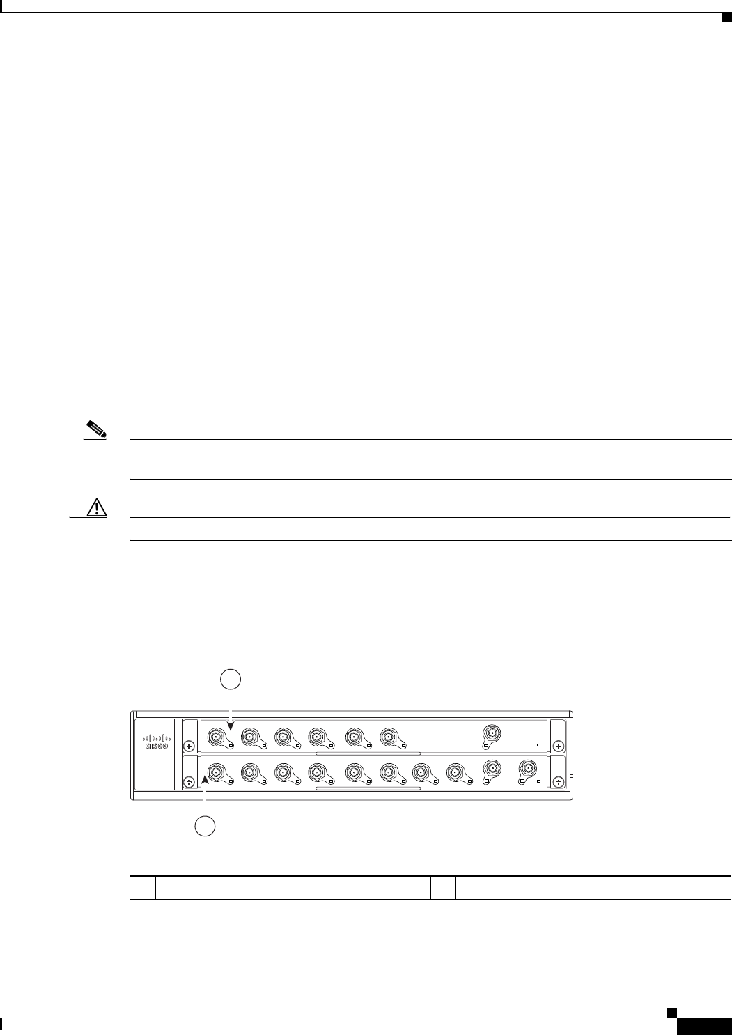
The front of the Cisco uBR7225VXR chassis provides access to two cable interface line cards. See
Figure 1-1.
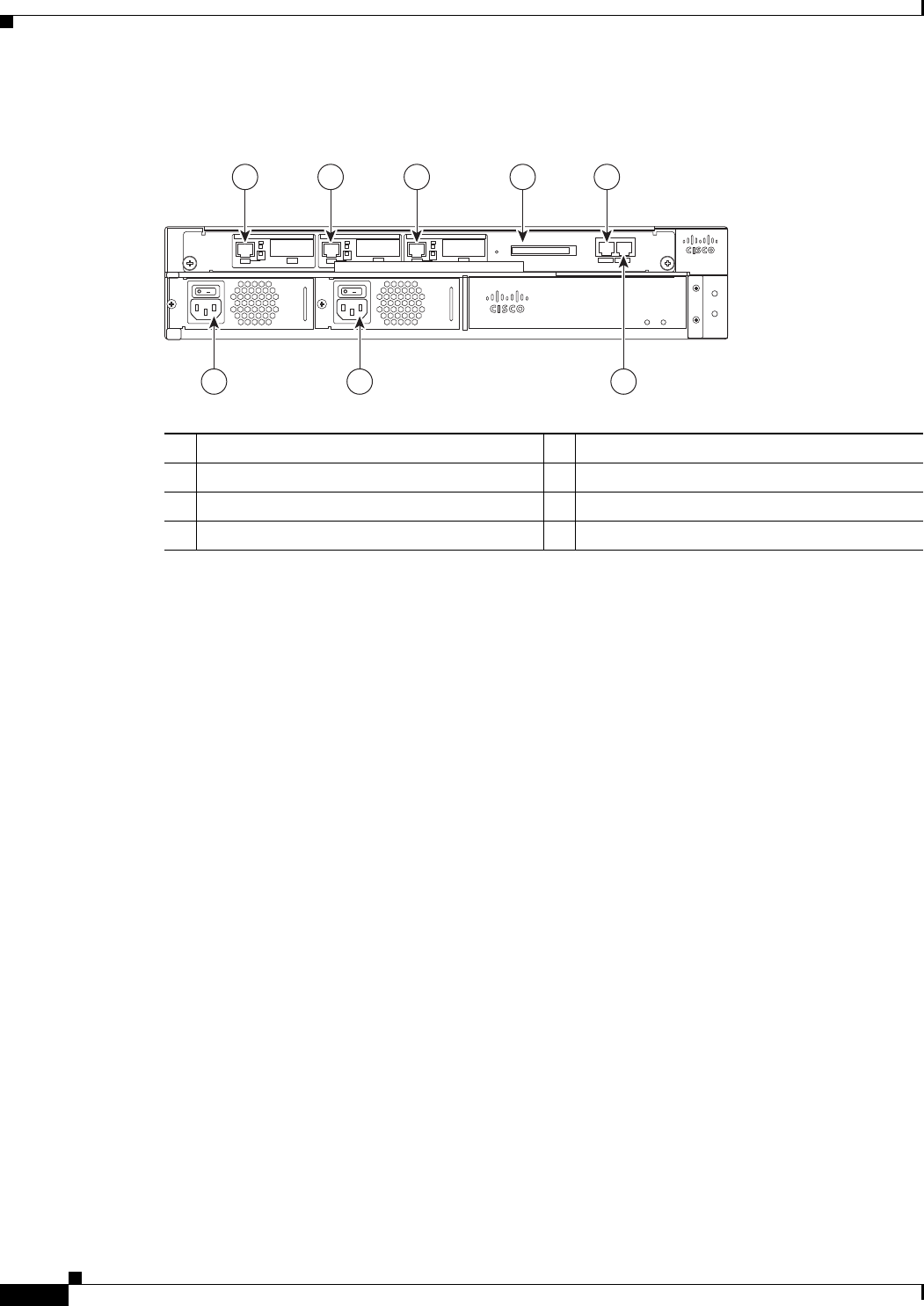
The rear of the Cisco uBR7225VXR provides access to the network processing engine and up to two
power supplies. See Figure 1-2.
A fully configured Cisco uBR7225VXR router can operate with only one installed power supply;
however, a second, optional power supply of the same type provides hot-swappable, load-sharing, and
redundant power. In a chassis using two power supplies, if one power supply fails or is removed, the
redundant power supply immediately takes over the router’s power requirements and maintains normal
operation without interruption.
The power supply has the router’s main power switch and an AC-input power receptacle. Mounting holes
for a ground lug are located on the far right side on the rear of the chassis, to provide a chassis ground
connection for ESD-preventive equipment. See Figure 3-13 on page 3-16.
Note Figure 1-2 shows the rear of a Cisco uBR7225VXR router configured with two 300W AC-input power
supplies.
Caution If you are using two power supplies, make sure that each one is plugged into a separate branch circuit.
A fully loaded router, with two installed power supplies (300 W) and all chassis slots filled, weighs
approximately 48 pounds (21.8 kg). For clearance requirements and rack-mount installation
considerations, refer to the “Site Environment” section on page 2-5.
Figure 1-1 Cisco uBR7225VXR Router—Front View
1Cable interface line card slot 1 2Cable interface line card slot 2
270489
uBR7225-VXR
US2
US4
US5
US6
US7
US1
US0
US3
US2
US4
US5
US1
US0
US3
uBR - MC28U
uBR - MC16U
DS0-RF
DS1-RF
DS0-RF
S
L
O
T
1
S
L
O
T
2
1
2
1-4
Cisco uBR7225VXR Universal Broadband Router Hardware Installation Guide
OL-17309-02
Chapter 1 Cisco uBR7225VXR Overview
Cisco uBR7225VXR Network Interface Overview
Figure 1-2 Cisco uBR7225VXR Router—Rear View
Cisco uBR7225VXR Network Interface Overview
This section provides a functional overview of the network interfaces available on the
Cisco uBR7225VXR universal broadband router, cable interface line card slot and logical interface
numbering, as well as the MAC address assignments for cable interface line card interfaces.
Card Slot and Logical Interface Numbering
In the Cisco uBR7200 series universal broadband routers, the slot number is the chassis slot in which a
cable interface card is installed.
Cable interface line card slots maintain the same slot number regardless of whether other cable interface
line cards are installed or removed. However, when you move a cable interface line card to a different
slot, the logical interface number changes to reflect the new slot number.
The MAC-layer or hardware address is a standardized data-link layer address that is required for certain
network interface types. These addresses are specific and unique to each port. The Cisco uBR7225VXR
uses a specific method to assign and control the MAC-layer addresses of its port adapters. For a
description of the MAC-layer address, refer to the “MAC-Layer Address” section on page 1-5.
The two cable interface line cards in the Cisco uBR7225VXR router provide the connection between the
router’s two PCI buses (mb1 and mb2) and external networks. See Figure 1-3.
1Gigabit Ethernet 0/1 5Console port
2Gigabit Ethernet 0/2 6Auxiliary port
3Gigabit Ethernet 0/3 7AC-input power supply 2
4CompactFlash Disk slot 8AC-input power supply 1
270490
uBR7225-VXR
uBR7225-VXR
1 2 3 4 5
8 7 6

1-5
Cisco uBR7225VXR Universal Broadband Router Hardware Installation Guide
OL-17309-02
Chapter 1 Cisco uBR7225VXR Overview
Cisco uBR7225VXR Network Interface Overview
Figure 1-3 Cisco uBR7255VXR Chassis and Cable Interface Line Cards
MAC-Layer Address
All LAN interfaces (ports) require unique MAC-layer addresses, also known as hardware addresses.
Typically, the MAC address of an interface is stored on a memory component that resides directly on the
interface circuitry; however, the OIR feature requires a different method. For a description of OIR, refer
to the “Online Insertion and Removal” section on page 5-1.
The OIR feature allows you to remove a cable interface line card and replace it with another identically
configured one. If the new cable interface line card matches the cable interface line card you removed,
the system immediately brings it online. In order to allow OIR, an address allocator with a unique MAC
address is stored in EPROM on the Cisco uBR7225VXR universal broadband router midplane. Each
address is reserved for a specific slot in the router regardless of whether a cable interface line card
resides in that slot.
The MAC addresses are assigned to the slots in sequence. This address scheme allows you to remove
cable interface cards and insert them into other universal broadband routers without causing the MAC
addresses to move around the network or be assigned to multiple devices.
Note Storing the MAC addresses for every slot in one central location means that the addresses stay with the
memory device on which they are stored.
For information on the commands used to configure your Cisco uBR7225VXR router, refer to the Cisco
IOS Configuration Fundamentals Configuration Guide at the following URL:
http://www.cisco.com/en/US/docs/ios/fundamentals/configuration/guide/12_4/cf_12_4_book.html
Also refer to the Cisco IOS Configuration Fundamentals Command Reference at the following URL:
http://www.cisco.com/en/US/docs/ios/fundamentals/command/reference/cf_book.html
270493
uBR7225-VXR
US2
US4
US5
US6
US7
US1
US0
US3
US2
US4
US5
US1
US0
US3
uBR - E28U
uBR - E18U
DS0-RF
DS1-RF
ENABLED
DS0-RF
ENABLED
1
2
1Cable interface line card slot 1 2Cable interface line card slot 2

1-6
Cisco uBR7225VXR Universal Broadband Router Hardware Installation Guide
OL-17309-02
Chapter 1 Cisco uBR7225VXR Overview
Supported System Configurations Overview
Supported System Configurations Overview
The Cisco uBR7200 series universal broadband routers is installed at a cable television headend or a
distribution hub. Related networking and RF equipment, servers, and other host computers are installed,
along with the Cisco uBR7225VXR router, to support digital data transmission.
To deliver data and VoIP services over the cable television system, TV channels are allocated to carry
digital data. Data is modulated downstream on:
•6-MHz channels in the 88 to 860 MHz range, using North American channel plans through
Cisco cable interface line cards installed in the chassis. For bidirectional cable plants, a portion of
the 5 to 42 MHz range is used for upstream data transmission. For one-way cable plants or cable
segments yet to be upgraded, DOCSIS-based cable interfaces configured for telco return are also
supported.
•8-MHz channels in the 108 to 862 MHz range using PAL/SECAM channel plans through
Cisco cable interface line cards installed in the chassis. For bidirectional cable plants, a portion of
the spectrum in the 5 to 65 MHz range is used for upstream data transmission.
•6-MHz channels in the 70 to 860 MHz range, using J-DOCSIS channel operation (extensions for
Japan and select regions) through Cisco cable interface line cards installed in the chassis. For
bidirectional cable plants, a portion of the 5 to 55 MHz range is used for upstream data transmission.
The following sections illustrate the supported configurations including:
•Basic Internet access services
•Virtual private network (VPN) services
•IP telephony services
•Telco return
Basic Internet Access Services
A Cisco uBR7225VXR universal broadband router is installed at the headend or distribution hub. The
Cisco uBR7225VXR downstream cable interface line cards, with onboard upconvertor, translate the
downstream signals to RF for broadcast. The Cisco uBR7225VXR router enables you to transmit
downstream data in both the 6-MHz North American or Japanese and the 8-MHz European channel
environments using the appropriate model of the cable interface line card.
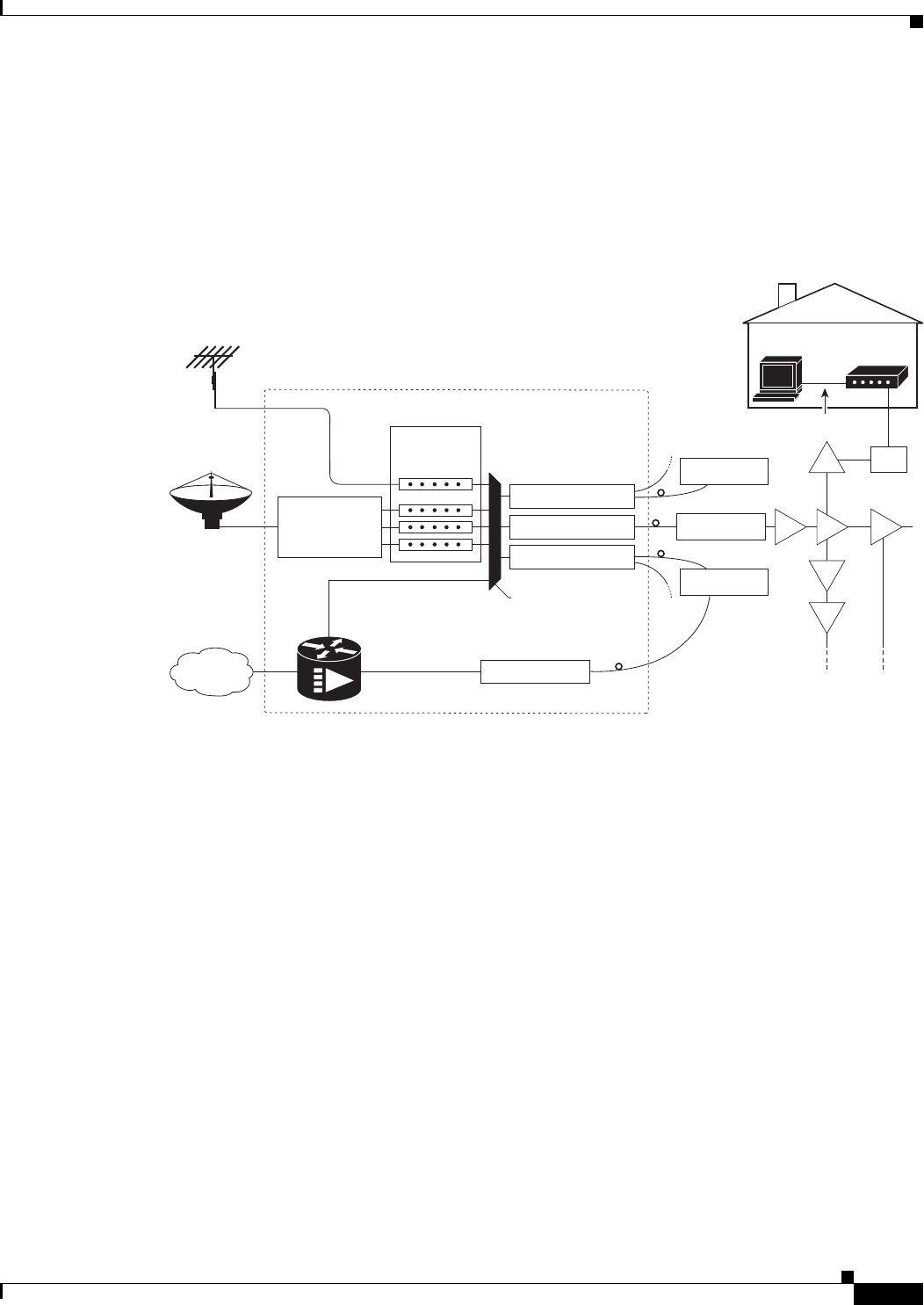
Receivers, scramblers, and descramblers process the television signals to encode or decode signals as
needed for broadcast. Modulators format the analog television and digital signals while upconverters
change the carrier frequency of a modulated signal to a specified frequency. The analog TV channels and
digitally modulated carriers then pass through the RF combiner.
The signals are broadcast from the headend through optical transmitters typically to fiber nodes in the
network. Amplifiers, coaxial cable, and taps carry the signals to the subscriber premises. Signals are
processed as follows:
•Set-top boxes (STBs), televisions, or VCRs receive analog and digital data signals.
•DOCSIS-based cable interfaces and STBs connected to customer premises equipment (CPE) receive
digital data signals:
–
Two-way cable interfaces transmit RF signals back through amplifiers to optical fiber receivers
at the headend. These receivers pass the upstream signal to the upstream ports on the
Cisco uBR7225VXR router for processing.
1-7
Cisco uBR7225VXR Universal Broadband Router Hardware Installation Guide
OL-17309-02
Chapter 1 Cisco uBR7225VXR Overview
Supported System Configurations Overview
–
Telco return cable interfaces transmit over the PSTN. Dial-up servers and other equipment
handle the upstream traffic and pass appropriate data to the Cisco uBR7225VXR routers. For
telco return specifics, refer to the “Telco Return” section on page 1-9.
Figure 1-4 shows the architecture of a typical two-way hybrid fiber-coaxial (HFC) network, equipped to
support two-way data communication.
Figure 1-4 Two-Way HFC Cable Network Example
Cisco provides a configuration tool—Cisco Network Registrar (CNR)—which is optimized for high
performance automatic dynamic IP address allocation to cable interfaces, PCs, and other devices on the
broadband network. Cisco also provides an integrated suite of configuration tools, including CNR, for
relatively large cable networks called Cisco Subscriber Registration Center (CSRC). CSRC allows
large-scale configuration and management of broadband modems. Leveraging the extensibility of CNR,
CSRC enables and administers subscriber self-registration. The directory-enabled architecture of CSRC
allows it to integrate with Lightweight Directory Access Protocol (LDAP) version 3 directory servers.
For more information on CSRC and CNR involvement in the cable network, refer to the CSRC and CNR
documentation.
Cisco Network Registrar Install and Upgrade Guide at the following URL:
http://www.cisco.com/en/US/products/sw/netmgtsw/ps1982/prod_installation_guides_list.html
Cisco Subscriber Registration Centre Installation Guide at the following URL:
http://www.cisco.com/en/US/products/sw/netmgtsw/ps2181/products_installation_guide_chapter09186
a0080086f1a.html
Also refer to the Cisco uBR7200 Series Software Configuration Guide at the following URL:
http://www.cisco.com/en/US/docs/cable/cmts/ubr7200/configuration/guide/cr72scg.html
Over the air
channels
Satellite
channels
Internet
Headend / Hub
Receivers
Descramblers
Scramblers
RF combiner
Subscriber
cable modem
Optical node
Optical node
Optical node
AM & digital
modulators
Optical transmitter
Optical transmitter
Optical transmitter
Optical receiver
RF amplifiers
271650
Cisco
uBR7225VXR
RF RF RF
RF
RF
RF Tap
Upstream
RF
Downstream
RF
10Base-T
1-8
Cisco uBR7225VXR Universal Broadband Router Hardware Installation Guide
OL-17309-02
Chapter 1 Cisco uBR7225VXR Overview
Supported System Configurations Overview
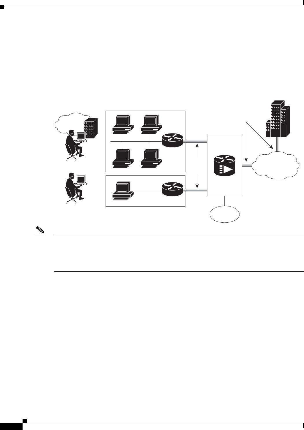
VPN Services
The Cisco uBR7225VXR router supports VPN services. Figure 1-5 shows a typical VPN architecture.
VPNs can be initiated at a cable modem residing at a subscriber site or can be initiated by the CMTS at
the headend or distribution hub depending upon your particular Cisco IOS software image.
Figure 1-5 Two-Way VPN Network Example
Note Many VPN architectures involve the use of encryption and decryption. Encryption and decryption are
subject to export licensing controls. For more information, refer to Regulatory Compliance and Safety
Information for Cisco uBR7200 Series Universal Broadband Routers, at the following URL:
http://www.cisco.com/en/US/docs/cable/cmts/ubr7200/regulatory/compliance/ub72rcsi.html
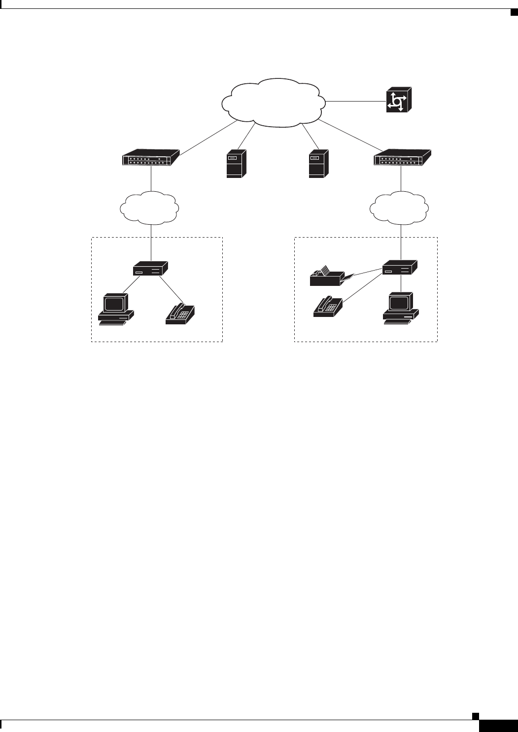
IP Telephony Services
The Cisco uBR7225VXR router supports the transmission of packetized voice and facsimile traffic over
the cable and IP backbone network. Figure 1-6 on page 1-9 shows a typical two-way configuration
involving Voice-over-IP (VoIP) telephony services.
271651
Branch
office
Secure
VPN
tunnels
Secure
VPN
tunnel
PSTN
Telecommuter
Internet
Corporate
Cisco
uBR7225VXR
1-9
Cisco uBR7225VXR Universal Broadband Router Hardware Installation Guide
OL-17309-02
Chapter 1 Cisco uBR7225VXR Overview
Supported System Configurations Overview
Figure 1-6 Two-Way IP Telephony Network Example
Telco Return
In telco return configurations, the Cisco uBR7225VXR universal broadband router provides downstream
data flow from cable interface line cards connected to the cable system and accepts upstream traffic via
a combination of the local PSTN and IP network path that terminates at the Cisco uBR7225VXR router.
Upstream data transmission takes place over a telephone modem (external or internal to a
cable interface, as well as a cable interface line card in a PC, based on the third-party cable interface
vendor) connected to an analog telephone line. Figure 1-7 on page 1-10 illustrates a telco return
configuration.
271652
Gatekeeper or
calling agents
Service
provider
backbone
HFC
cable plant
HFC
cable plant
Remote
cable modem
Remote
cable modem
Gateway/PSTN
Calling party
Residence or SOHO*
subscriber site 1
Residence or SOHO*
subscriber site 2
Called party
Policy
server
*Small Office Home Office
Cisco
uBR7225VXR
Cisco
uBR7225VXR

1-10
Cisco uBR7225VXR Universal Broadband Router Hardware Installation Guide
OL-17309-02
Chapter 1 Cisco uBR7225VXR Overview
Hardware Component Descriptions
Figure 1-7 Telco Return Network Example
Hardware Component Descriptions
Most Cisco uBR7225VXR universal broadband router components are field-replaceable units (FRUs).
These units, unless otherwise noted, are OIR compatible. See the “Online Insertion and Removal”
section on page 5-1
FRU documentation (instructions on installing, removing, and replacing) is located at the following
URL:
http://www.cisco.com/en/US/products/hw/routers/ps341/prod_installation_guides_list.html
The following components are described:
•Network Processing Engine, page 1-10
•Cisco Cable Interface Line Cards, page 1-12
•Power Supplies, page 1-13
•Fan Trays, page 1-14
•Cisco uBR7225VXR Chassis, page 1-17
•Subchassis and Midplane, page 1-17
•CompactFlash Disk, page 1-18
Network Processing Engine
The network processing engine (NPE) maintains and executes the system management functions for the
Cisco uBR7225VXR router. The network processing engine performs the following system management
functions:
IP network access
RADIUS dial
security server
Upstream
Subscriber
cable modem
HFC downstream
including TCD messages
271653
DHCP
TFTP
TOD
servers
Cisco network
access server
PPP connection between
remote cable modem
and network access server
established following
authentication
Headend or hub
PSTN
IP network
Cisco
uBR7225VXR

1-11
Cisco uBR7225VXR Universal Broadband Router Hardware Installation Guide
OL-17309-02
Chapter 1 Cisco uBR7225VXR Overview
Hardware Component Descriptions
•Sending and receiving routing protocol updates
•Managing tables, caches, and buffers
•Monitoring interface and environmental status
•Providing Simple Network Management Protocol (SNMP) management and console/Telnet
interface
•Accounting and switching of data traffic
•Booting and reloading images
Refer to Network Processing Engine and Network Services Engine Installation and Configuration, for
specifications, and removal and replacement instructions for these components. View the document
online at the following URL:
http://www.cisco.com/en/US/docs/routers/7200/install_and_upgrade/network_process_engine_install_
config/npense.html
A CPU reset button is located on the NPEs’ faceplate. The CPU reset button resets the entire system.
Caution To prevent system errors and problems, use the CPU reset button only at the direction of your service
representative.
NPE Comparisons
The network processing engines used in the Cisco uBR7225VXR router are the Cisco uBR7200-NPE-G1
and Cisco uBR7200-NPE-G2.
Note The Cisco uBR7200-NPE-G1 should use the boothelper image ubr7200-kboot-mz.122-33.SCA.bin
available from Cisco IOS Release 12.3(33)SCA and later. The Cisco uBR7200-NPE-G2 should use the
boothelper image ubr7200p-boot-mz.122-33.SCA1.bin available from Cisco IOS Release 12.3(33)SCB
and later.
NPE components:
•Reduced instruction set computing (RISC) microprocessor:
–
Cisco uBR7200-NPE-G1 with a 700-MHz Broadcom BCM1250 processor
–
Cisco uBR7200-NPE-G2 with a 1.67-GHz Motorola Freescale MPC7448 processor
•System controller:
–
Cisco uBR7200-NPE-G1 and Cisco uBR7200-NPE-G2 do not require an I/O controller.
•Upgradable memory modules:
–
Cisco uBR7200-NPE-G1—SDRAM: 256 MB (default), 512 MB, and 1 GB. There are two
DRAM memory slots, so 256 MB of memory consists of two 128-MB memory SODIMMs, 512
MB consists of two 256-MB memory SODIMMs, and 1 GB consists of two 512-MB memory
SODIMMs. It is necessary to have the same size SODIMM in each memory bank on an
NPE-G1. The type of DRAM memory being used on the NPE-G1 is double data-rate (DDR)
memory. DDR memory provides high-performance memory access rates.

1-12
Cisco uBR7225VXR Universal Broadband Router Hardware Installation Guide
OL-17309-02
Chapter 1 Cisco uBR7225VXR Overview
Hardware Component Descriptions
–
Cisco uBR7200-NPE-G2—SDRAM: 1 GB (default) and 2 GB. There are two DRAM memory
slots, so 1 GB of memory consists of two 512-MB memory SODIMMs, and 2 GB consists of
two 1 GB memory SODIMMs. It is necessary to have the same size SODIMM in each memory
bank on an NPE-G2. The type of DRAM memory being used on the NPE-G2 is double data-rate
(DDR) memory. DDR memory provides high-performance memory access rates.
•Cache memory:
–
Cisco uBR7200-NPE-G1—16-MB packet memory on 256-MB SDRAM, and 32-MB packet
memory on 512-MB and 1-GB SDRAM.
–
Cisco uBR7200-NPE-G2—32-MB packet memory on 512-MB and 1-GB SDRAM.
•Two environmental sensors for monitoring the cooling air as it leaves the chassis.
•Boot ROM for storing sufficient code for booting the Cisco IOS software.
For memory replacement instructions, refer to the Memory Replacement Instructions for the Network
Processing Engine or Network Services Engine and Input/Output Controller document at the following
URL:
http://www.cisco.com/en/US/docs/routers/7200/install_and_upgrade/npe-nse_memory_install/memory
.html
Cisco Cable Interface Line Cards
Cisco cable interface line cards (also known as line cards), with internal IF-to-RF upconverters, serve as
the RF interface between the cable headend and both DOCSIS-based cable modems and
EuroDOCSIS-based cable modems and set-top boxes (STBs). Cisco cable interface line cards separate
downstream output and upstream input cable interfaces on the Cisco uBR7225VXR router to enable
downstream and upstream signal combining and splitting arrangements.
Cisco cable interface line cards can be used in both 6-MHz NTSC standard and 8-MHz PAL/SECAM
channel environments.
The cable interface line cards connect directly to the universal broadband router’s midplane. Cable
interface line cards installed in the Cisco uBR7225VXR router support OIR.
Caution To ensure the proper flow of cooling air across internal components, make sure that blank cable interface
line card is installed in an unoccupied chassis slot. Also make sure that power supply filler plates are
installed in unoccupied power supply bays.
For more information regarding specific cable interface line cards, refer to the Cisco uBR7200 Series
Cable Interface Line Card Hardware Installation Guide. To view the document online, go to the
following URL:
http://www.cisco.com/en/US/docs/interfaces_modules/cable/line_cards/installation/guide/mcxxfru.htm
l

1-13
Cisco uBR7225VXR Universal Broadband Router Hardware Installation Guide
OL-17309-02
Chapter 1 Cisco uBR7225VXR Overview
Hardware Component Descriptions
Power Supplies
The Cisco uBR7225VXR router is equipped with one of the following power supplies:
•300W AC-input power supply—The maximum AC-input power with single or dual power supply
configuration is 300W. The minimum Cisco IOS Release supported on this power supply is the
Cisco IOS Release 12.2(33)SCA.
•540W AC-input power supply—The maximum AC-input power with single or dual power supply
configuration is less than 700W. The minimum Cisco IOS Release supported on this power supply
is the Cisco IOS Release 12.2(33)SCD.
Note Ensure that you do not use a combination of these power supplies in the Cisco uBR7225VXR router.
The power supply contains a main power switch, Input OK and Output OK LEDs, AC-input power
receptacle, and a two-hole grounding lug for the AC-input power supply. The grounding lug at the
rear-bottom portion of the chassis provides a ground connection for electrostatic discharge (ESD)
equipment.
The Cisco uBR7225VXR router supports an optional, second power supply for load-sharing and power
redundancy. If you purchased a Cisco uBR7225VXR router and you want to install a second power
supply, you must order the second power supply separately.
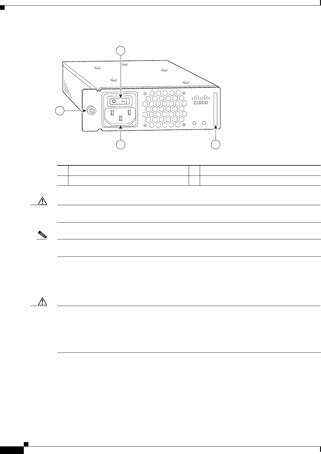
A handle on the AC-input power supply unit provides a grip point for removing and replacing the power
supply. (Figure 1-8 on page 1-14 shows the faceplate of the AC-input power supply.)
A single captive installation screw secures the power supply to the chassis and seats the power supply in
the router midplane. The AC-input power supply has a receptacle for an AC-input power cable. A
modular power cable connects the AC-input power supply to the site AC power source.
Detailed instructions for handling and replacing the Cisco uBR7225VXR universal broadband router
power supply is available in Cisco uBR7200 Series Universal Broadband Router AC Power Supply
Replacement Instructions.
This document is available on Cisco.com at the following URL:
http://www.cisco.com/en/US/docs/cable/cmts/ubr7200/installation/4848pwra.html
Note For the Cisco uBR7225VXR router, the 300W AC-input power supply has an electrical input current
rating of 4A with 100Vac input and the 540W AC-input power supply has an electrical input current
rating of 6.5A with 100Vac input.
1-14
Cisco uBR7225VXR Universal Broadband Router Hardware Installation Guide
OL-17309-02
Chapter 1 Cisco uBR7225VXR Overview
Hardware Component Descriptions
Figure 1-8 Cisco uBR7225VXR AC-Input Power Supply
Caution To ensure adequate airflow across the Cisco uBR7225VXR power supplies, a power supply or a power
supply filler plate (with its attached air dam) must be installed in each power supply bay.
Note See Appendix A, “Cisco uBR7225VXR Router Specifications,” for AC-input power supply system
power specifications, including input voltage and operating frequency ranges.
The Cisco uBR7225VXR power supply shuts itself down when the input AC voltage, the output DC
voltage, or the internal temperature of the chassis exceeds allowable tolerances. When this occurs, one
or both of the power supply front panel LEDs will turn red. The Cisco uBR7225VXR power supply must
then be reset by manually switching the power switch off and then back on to allow the router to recover.
Caution When the input power to Cisco uBR7225VXR power supply is disconnected or lost, the power supply
enters a reset cycle for 10 seconds. Wait at least 10 seconds or move the power switch from one position
to the other to restart the power supply. For example, if the power supply was on when the power was
disconnected or lost, move the power switch to the off position and then back to the on position. If you
do not wait the full 10 seconds or move the power switch from one position to the other, the power supply
does not restart.
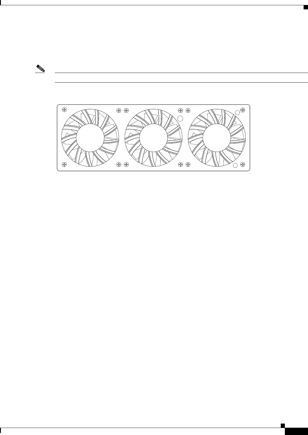
Fan Trays
The fan tray for the Cisco uBR7225VXR router, shown in Figure 1-9, consisting of three fans that are
attached to a metal tray, is located on the left side of the chassis (when viewing the router from the front)
and receives 12 VDC through a DC power harness that connects directly to the router midplane.
270698
PWR-UBR7225VXR-AC
100-240 VAC
4-2 A
50-60 Hz
Input
OK
Output
OK
1
23
4
1Power switch 3AC-input receptable
2Handle 4Captive installation screw
1-15
Cisco uBR7225VXR Universal Broadband Router Hardware Installation Guide
OL-17309-02
Chapter 1 Cisco uBR7225VXR Overview
Hardware Component Descriptions
Temperature sensors on the network processing engine monitor the internal air temperature and send
warning messages when the internal air temperature approaches a specified threshold. If the internal
temperature exceeds the specified threshold, the system environmental monitor shuts down all internal
power to prevent equipment damage from excessive heat.
Note The Cisco uBR7225VXR router fan tray is not a field-replaceable unit.
Figure 1-9 Cisco uBR7225VXR Fan Tray
The fan tray draws cooling air in through the intake vent on the right side of the chassis (when viewing
the router from the front) and moves the air across the internal components and sends it out through the
exhaust vent on the left side of the chassis. Figure 1-10 shows the airflow through the router.
The left and right sides of the chassis must remain unobstructed to ensure adequate airflow and prevent
overheating inside the chassis; we recommend at least 3 inches of clearance. (See the “Site
Requirements” section on page 2-5.)
270537

1-16
Cisco uBR7225VXR Universal Broadband Router Hardware Installation Guide
OL-17309-02
Chapter 1 Cisco uBR7225VXR Overview
Hardware Component Descriptions
Figure 1-10 Internal Airflow—Top View
271654
1
3
4 2
1Power supply end 3Cable interface line card end
2Inlet flow 4Exhaust air (fan side)
1-17
Cisco uBR7225VXR Universal Broadband Router Hardware Installation Guide
OL-17309-02
Chapter 1 Cisco uBR7225VXR Overview
Hardware Component Descriptions
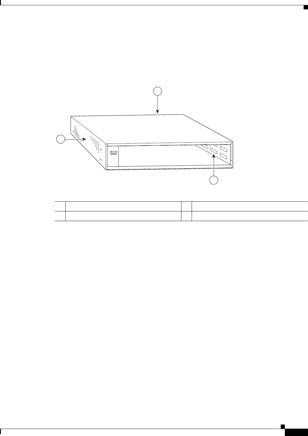
Cisco uBR7225VXR Chassis
The front of the chassis has two slots for cable interface line cards and one bay for the subchassis. See
Figure 1-11.
Figure 1-11 Cisco uBR7225VXR Chassis
Subchassis and Midplane
The subchassis and midplane provide these functions for the Cisco uBR7225VXR router:
•Distributes power from the power supply.
•Bridges the peripheral component interconnect (PCI) buses from the cable interface line cards to the
Cisco uBR7200-NPE-G1 or the Cisco uBR7200-NPE-G2.
•Arbitrates traffic across the PCI buses.
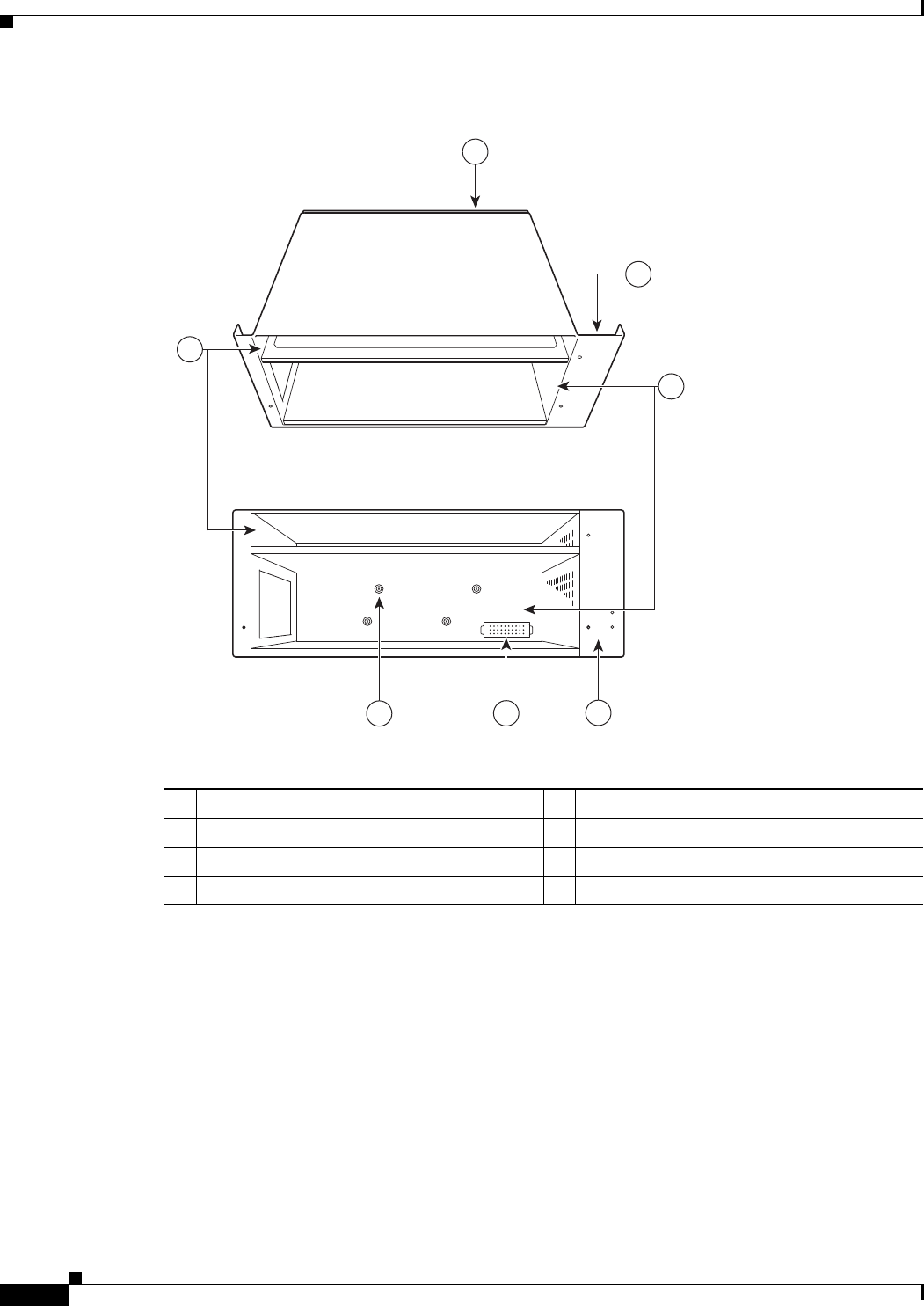
Cisco uBR7225VXR Subchassis
The subchassis (the rear of the router) has two bays for power supplies and one slot for a network
processing engine. (See Figure 1-12.) The cable interface card side of the Cisco uBR7225VXR router
midplane has two connectors for cable interface line cards.
The power supply side of the midplane has two connectors for power supplies and one connector for a
network processing engine. The midplane supplies DC power to the router’s internal components.
Refer to the Cisco uBR7200 Series Universal Broadband Router Subchassis and Midplane Replacement
Instructions at the following URL:
http://www.cisco.com/en/US/docs/cable/cmts/ubr7200/installation/5193sbm.html
270494
uBR7225-VXR
1
2
3
1Subchassis and midplane bay (at rear) 3Fan tray
2Cable interface line card slots
1-18
Cisco uBR7225VXR Universal Broadband Router Hardware Installation Guide
OL-17309-02
Chapter 1 Cisco uBR7225VXR Overview
Hardware Component Descriptions
Figure 1-12 Cisco uBR7225VXR Subchassis and Midplane
CompactFlash Disk
The Cisco uBR7225VXR universal broadband router has one CompactFlash Disk slot that uses
CompactFlash Disks. The device in this slot is always addressed as disk2: when using Cisco IOS
command-line interface (CLI) commands.
CompactFlash Disks are smaller in size than Type 2 Flash Disks but provide the same AT Attachment
(ATA) interface and equivalent functionality. This interface complies with the ANSI ATA Interface
Document X3T13.1153 D Rev. 9 specification. The CompactFlash Disk provides 512 MB or 1 GB of
storage space.
271655
Back
Top
1
4
7
2
3
65
1Midplane 5Power supply receptacle
2Fan tray slot 6Captive installations screws (6)
3Power supply bays 7Network processing engine slot
4Fan tray slot

1-19
Cisco uBR7225VXR Universal Broadband Router Hardware Installation Guide
OL-17309-02
Chapter 1 Cisco uBR7225VXR Overview
Hardware Component Descriptions
The CompactFlash Disk has controller circuitry that allows it to emulate a hard disk and automatically
maps out bad blocks and performs automatic block erasure. The CompactFlash Disk also provides the
capability to allocate noncontiguous sectors, which eliminates the need for the squeeze command (which
was required with older-style linear flash memory cards to recover the space used by deleted files).
The CompactFlash Disk also supports the Cisco IOS File System feature, which provides a single
interface to all of the router’s file systems, including the Flash Disks and flash memory, as well as
network file systems such as File Transfer Protocol (FTP) and Trivial FTP (TFTP) servers.
Note All CompactFlash Disks must be formatted before their initial use. CompactFlash Disks shipped with
the NPE-G2 are formatted at the factory, but spare memory cards are not formatted.

1-20
Cisco uBR7225VXR Universal Broadband Router Hardware Installation Guide
OL-17309-02
Chapter 1 Cisco uBR7225VXR Overview
Hardware Component Descriptions

CHAPTER
2-1
Cisco uBR7225VXR Universal Broadband Router Hardware Installation Guide
OL-17309-02
2
Preparing the Cisco uBR7225VXR Router for
Installation
This chapter describes the site requirements for installing the Cisco uBR7225VXR universal broadband
router and contains the following sections:
•Safety Recommendations, page 2-1
•Site Requirements, page 2-5
•Required Network Information, page 2-7
•Installation Tools, page 2-8
•Rack-Mount and Cable-Management Kit, page 2-8
•Equipment Required to Verify Your Plant’s RF Setup, page 2-9
•Shipping Container Contents, page 2-9
•Provisioning the Cable Headend, page 2-10
•Site Preparation Checklist, page 2-17
•Component Checklists, page 2-18
Safety Recommendations
The following safety guidelines will help to ensure your safety and protect the equipment. This list does
not cover all potentially hazardous situations, so be alert. Before installing, configuring, or maintaining
the Cisco uBR7225VXR router, review the safety warnings listed in the Regulatory Compliance and
Safety Information for Cisco uBR7200 Series Universal Broadband Routers at the following URL:
http://www.cisco.com/en/US/docs/cable/cmts/ubr7200/regulatory/compliance/ub72rcsi.html
The installation of your Cisco uBR7225VXR universal broadband router should be in compliance with
national and local electrical codes.
Other safety issues to be aware of:
•Never attempt to lift an object that might be too heavy for you to lift by yourself.
•Always turn all power supplies off and unplug all power cables before opening the chassis.
•Always unplug the power cable before installing or removing a chassis.
•Keep the chassis area clear and dust-free during and after installation.
•Keep tools and chassis components away from walk areas.

2-2
Cisco uBR7225VXR Universal Broadband Router Hardware Installation Guide
OL-17309-02
Chapter 2 Preparing the Cisco uBR7225VXR Router for Installation
Safety Recommendations
•Do not wear loose clothing, jewelry (including rings and chains), or other items that could get caught
in the chassis.
•For systems with installed AC-input power supplies, the Cisco uBR7225VXR router ships with a
3-wire electrical grounding-type plug, which only fits into a grounding-type power outlet. This is a
safety feature. The equipment grounding should be in accordance with local and national electrical
codes.
•The Cisco uBR7225VXR router operates safely when it is used in accordance with its marked
electrical ratings and product usage instructions.
Warning
Only trained and qualified personnel should be allowed to install or replace this equipment.
Statement 1030
Note For Australia and New Zealand, equipment is to be installed and maintained by service personnel only
as defined by AS/NZS 3260 Clause 1.2.14.3 Service Personnel.
Warning
Ultimate disposal of this product should be handled according to all national laws and regulations.
Statement 1040
Lifting the Cisco uBR7225VXR Router Safely
Before you install the router, ensure that your site configuration is properly designed and prepared so
that you can avoid having to move the router later to accommodate power sources and network
connections.
A fully-configured Cisco uBR7225VXR router (with two 300W power supplies) weighs approximately
48 pounds (21.8 kilograms).
Whenever you lift a chassis or any heavy object, follow these guidelines:
•Always disconnect all external cables before lifting or moving the chassis.
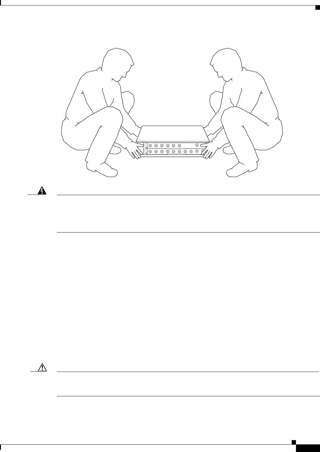
•Do not attempt to lift the chassis by yourself; have someone assist you (see Figure 2-1 on page 2-3).
•Ensure that your footing is solid, and balance the weight of the object between your feet.
•Lift the chassis slowly; never move suddenly or twist your body as you lift.
•Keep your back straight and lift with your legs, not your back. If you must bend down to lift the
chassis, bend at the knees, not at the waist, to reduce the strain on your lower back muscles.
•Lift the chassis from the bottom; grasp the underside of the chassis exterior with both hands.
2-3
Cisco uBR7225VXR Universal Broadband Router Hardware Installation Guide
OL-17309-02
Chapter 2 Preparing the Cisco uBR7225VXR Router for Installation
Safety Recommendations
Figure 2-1 Lifting the Chassis (Cisco uBR7246 Router Shown)
Warning
Two people are required to lift the chassis. Grasp the chassis underneath the lower edge and lift with
both hands. To prevent injury, keep your back straight and lift with your legs, not your back. To prevent
damage to the chassis and components, never attempt to lift the chassis with the handles on the
power supplies or on the interface processors, or by the plastic panels on the front of the chassis.
These handles were not designed to support the weight of the chassis.
Statement 5
Safety with Electricity
Follow these basic guidelines when working with any electrical equipment:
•Before beginning any procedures requiring access to the chassis interior, locate the emergency
power-off switch for the room in which you are working.
•Carefully examine your work area for possible hazards such as moist floors, ungrounded power
extension cables, and missing safety grounds.
•Disconnect all power and external cables before installing or removing a chassis.
•Never assume that power has been disconnected from a circuit; always check.
•Do not perform any action that creates a potential hazard to people or makes the equipment unsafe.
•Do not work alone if potentially hazardous conditions exist.
•Never install equipment that appears damaged.
Caution Yo u must power down the system before removing or replacing the network processing engine. The cable
interface line cards and redundant power supplies are designed to be removed and replaced while the
system is operating, without presenting an electrical hazard or damage to the system.
271656

2-4
Cisco uBR7225VXR Universal Broadband Router Hardware Installation Guide
OL-17309-02
Chapter 2 Preparing the Cisco uBR7225VXR Router for Installation
Safety Recommendations
Warning
The telecommunications lines must be disconnected 1) before unplugging the main power connector
and/or 2) while the housing is open.
Statement 89
Warning
Before working on a chassis or working near power supplies, unplug the power cord on AC units;
disconnect the power at the circuit breaker on DC units.
Statement 246
Warning
Do not work on the system or connect or disconnect cables during periods of lightning activity.
Statement 1001
In addition, use the guidelines that follow when working with any equipment that is disconnected from
a power source, but still connected to telephone wiring or other network cabling:
•Never install telephone wiring during a lightning storm.
•Never install telephone jacks in wet locations unless the jack is specifically designed for wet
locations.
•Never touch uninsulated telephone wires or terminals unless the telephone line has been
disconnected at the network interface.
•Use caution when installing or modifying telephone lines.
Preventing Electrostatic Discharge Damage
Electrostatic discharge (ESD) damage, which occurs when electronic cards or components are
improperly handled, can result in complete or intermittent system failures. The network processing
engine and cable interface line cards consist of a printed circuit board that is fixed in a metal carrier.
Electromagnetic interference (EMI) shielding, connectors, and a handle are integral components of the
carrier. Although the carrier helps protect the boards, use an antistatic strap whenever handling the
network processing engine and cable interface cards. Handle the carriers by the handles and the carrier
edges only; never touch the boards or connector pins.
Caution Always tighten the captive installation screws on the network processing engine and cable interface line
cards. These screws prevent accidental removal, provide proper grounding for the system, and help
ensure that the bus connectors are properly seated in the midplane.
Following are guidelines for preventing ESD damage:
•Always use an ESD wrist strap or ankle strap and ensure that it makes good skin contact.
•When handling a removed network processing engine or cable interface line card, make sure that the
equipment end of your ESD strap is attached to an unfinished chassis surface of the router; do not
touch the printed circuit board, and avoid contact between the printed circuit board and your
clothing. Always place the network processing engine or cable interface line card component side
up on an antistatic surface or in a static shielding bag. If you are returning the item to the factory,
immediately place it in a static shielding bag.

2-5
Cisco uBR7225VXR Universal Broadband Router Hardware Installation Guide
OL-17309-02
Chapter 2 Preparing the Cisco uBR7225VXR Router for Installation
Site Requirements
•Ensure that the network processing engine is fully inserted in its chassis slot and the captive
installation screws are tightened. The captive installation screws prevent accidental removal,
provide proper grounding for the system, and help ensure that the bus connectors are seated in the
midplane.
•Ensure that each cable interface line card is fully inserted in its chassis slot and that its captive
installation screws are tightened.
Caution For safety, periodically check the resistance value of the antistatic strap. The measurement should be
between 1 and 10 megohms.
Site Requirements
To ensure normal operation and avoid unnecessary maintenance, plan your site configuration and
prepare your site before installation. Take into account the following criteria:
•Verify that your cable network meets system requirements and DOCSIS or EuroDOCSIS
downstream and upstream specifications.
•Select forward and reverse channel frequencies from the range specified in your channel plan.
•Make sure that the site maintains an ambient temperature of 32 to 104oF (0 to 40oC), and keep the
area around the chassis as free from dust as is practical.
Note To locate the most reliable channels for your downstream and upstream channel plans, we recommend
that you perform a sweep of all available channels for at least a 24-hour period to verify the presence or
absence of impulse or ingress noise.
AC Power
The AC-input power supply uses a power factor corrector that allows the Cisco uBR7225VXR router to
operate on input voltage and frequency within the ranges of 100 to 240 VAC and 50/60 Hz.
Note We recommend an uninterruptable power source to protect against power failures at your site. For the
Cisco uBR7225VXR router, the 300W AC-input power supply has an electrical input current rating of
4A with 100Vac input and the 540W AC-input power supply has an electrical input current rating of 6.5A
with 100Vac input.
See Appendix A, “Cisco uBR7225VXR Router Specifications,” for system power specifications,
including input voltage and operating frequency ranges.
Site Environment
Table 2-1 lists the operating and nonoperating environmental site requirements. The following ranges
are those within which the Cisco uBR7225VXR router continues to operate; however, a measurement
that is approaching the minimum or maximum of a range indicates a potential problem. You can maintain
normal operation by anticipating and correcting environmental anomalies before they approach the
minimum or maximum of an operating range.

2-6
Cisco uBR7225VXR Universal Broadband Router Hardware Installation Guide
OL-17309-02
Chapter 2 Preparing the Cisco uBR7225VXR Router for Installation
Site Requirements
To provide airflow through the Cisco uBR7225VXR router, cooling air is drawn in through the air intake
vent on the right side of the chassis (when viewing the router from the front) and is exhausted through
the left side of the chassis. Keep the right and left sides of the chassis clear of obstructions and away
from the exhaust of other equipment.
Note The Cisco uBR7225VXR router is suitable for installation in Network Telecommunication Facilities and
locations where the National Electrical Code (NEC) applies. The Cisco uBR7225VXR router is not
intended for installation in outside plant (OSP) locations.
Site Configuration: Maintaining Normal Operation
Planning a proper location for the Cisco uBR7225VXR universal broadband router and the layout of
your equipment rack or wiring closet are essential for successful system operation. Equipment placed
too close together or inadequately ventilated can cause system overtemperature conditions. In addition,
chassis panels made inaccessible by poor equipment placement can make system maintenance difficult.
Following are precautions that can help avoid problems during installation and ongoing operation.
General Precautions
Follow these general precautions when planning your equipment locations and connections:
•Use the show environment command regularly to check the internal system status. The
environmental monitor continually checks the interior chassis environment; it provides warnings for
high temperature and maximum and minimum voltages and creates reports on any occurrences. If
warning messages are displayed, take immediate action to identify the cause and correct the
problem.
•We recommend keeping the Cisco uBR7225VXR router off the floor and out of any area that tends
to collect dust, excessive condensation, or water.
•Follow ESD prevention procedures to avoid damage to equipment. Damage from static discharge
can cause immediate or intermittent equipment failure.
Table 2-1 Specifications for Operating and Nonoperating Environments
Specification Minimum Maximum
Temperature, ambient operating 32oF (0oC) 104oF (40oC)
Temperature, ambient nonoperating and storage –4oF (–20oC) 149oF (65oC)
Humidity, ambient (noncondensing) operating 10% 90%
Humidity, ambient (noncondensing) nonoperating
and storage
5% 95%
Altitude, operating and nonoperating Sea level 10,000 feet (3,050 meters)
Vibration, operating 5 to 200 Hz, 0.5 g (1 oct./min.) –
Vibration, nonoperating 5 to 200 Hz, 1 g (1 oct./min.)
200 to 500 Hz, 2 g (1 oct./min.)
–

2-7
Cisco uBR7225VXR Universal Broadband Router Hardware Installation Guide
OL-17309-02
Chapter 2 Preparing the Cisco uBR7225VXR Router for Installation
Required Network Information
•Ensure that the network processing engine, cable interface line cards, any blank cable interface line
cards, power supplies, and any power supply filler plates are in place and secure. The fans direct
cooling air throughout the chassis interior; a loose component or empty slot can redirect the airflow
away from active components and cause overheating.
Power Considerations
Follow these precautions and recommendations when planning power connections to the
Cisco uBR7225VXR router:
•Check the power at your site before installation and periodically after installation to ensure that you
are receiving clean power. Install a power conditioner and appropriate surge suppression if
necessary.
•Install proper grounding to avoid damage from lightning and power surges.
Required Network Information
After you install the chassis, your system administrator must configure the individual and system
interfaces before you connect your system to external networks. Refer to the following documentation
for configuration information.
Cisco uBR7200 Series Software Configuration Guide at the following URL:
http://www.cisco.com/en/US/docs/cable/cmts/ubr7200/configuration/guide/cr72scg.html
Cisco IOS CMTS Cable Software Configuration Guide at the following URL:
http://www.cisco.com/web/techdoc/cable/Config/Sw_conf.html
Cisco IOS CMTS Cable Command Reference Guide at the following URL:
http://www.cisco.com/en/US/docs/ios/cable/command/reference/cbl_book.html
Before You Begin
Be prepared with global (system-wide) parameters such as:
•Hostnames
•Passwords
•Routing protocols
•Configuration information for each interface, such as:
–
Addresses
–
Rates or speeds of operation
–
Routing protocol specifics
Following is the information you might need, depending on the services you plan to offer:
•Hostname for the router.
•Passwords to prevent unauthorized privileged-level access to the EXEC command interpreter and
for individual virtual terminal lines.
•Protocols you plan to route.

2-8
Cisco uBR7225VXR Universal Broadband Router Hardware Installation Guide
OL-17309-02
Chapter 2 Preparing the Cisco uBR7225VXR Router for Installation
Installation Tools
•IP addresses and subnet masks, if you are routing IP.
•Dial-up access telephone numbers, usernames, and passwords for telco return operation.
•RADIUS security and accounting configuration.
•Gateway and gatekeeper zone configuration for your H.323 VoIP network.
•Gateway and call-agent configuration for your SGCP VoIP network.
•Zone names, network numbers, or node numbers for the new interfaces, if required.
•Operating speeds for specific interfaces—For example, serial interfaces operate at speeds of up to
2 Mbps. The speed of an interface often depends on the speed of the remote device to which it is
attached.
Installation Tools
Your Cisco uBR7225VXR universal broadband router chassis is fully assembled at the factory; no
assembly is required. However you will need the following tools and equipment to install the chassis and
the rack-mount and cable-management kit:
•Number 2 Phillips screwdriver
•3/16-inch flat-blade screwdriver
•7/16-inch flat-blade screwdriver
•7/16-inch torque wrench for connecting coaxial cables to the cable F-connectors on the
cable interface line cards—Recommended torque is 20 inch-pounds (optional)
•Tape measure (optional)
•Level (optional)
Rack-Mount and Cable-Management Kit
The rack-mount and cable-management kit includes the following parts:
•Two rack-mount brackets for mounting the chassis in the rack.
•Cable-management bracket to relieve the strain on installed cable interface line card interface
cables.
•Eight M4 x 6-mm Phillips flathead screws to secure the rack-mount brackets to the chassis.
•Four M3 x 6-mm Phillips panhead screws to secure the cable-management bracket to the chassis.
•Four 10/32 x 3/8-inch slotted binderhead screws to secure the rack-mount brackets to the rack rails.
For more information on the rack-mount brackets and cable-management bracket, refer to the
“Cisco uBR7225VXR Router Chassis Rack-Mounting Options” section on page 3-2.

2-9
Cisco uBR7225VXR Universal Broadband Router Hardware Installation Guide
OL-17309-02
Chapter 2 Preparing the Cisco uBR7225VXR Router for Installation
Equipment Required to Verify Your Plant’s RF Setup
Equipment Required to Verify Your Plant’s RF Setup
To verify your plant’s RF setup, you need the following:
•RF spectrum analyzer
•For coaxial cabling:
–
Diplex filters/splitters
–
Coaxial cable crimping tool
–
New coaxial cable
–
Coaxial jumpers that are at least 2 to 3 feet long (maximum of 5 feet)
•For fiber networks, optical receivers for each upstream optical path
•Assorted RF attenuators (with at least two 20-dB attenuators)
Note For headend RF and data setups, refer to Chapter 4, “Connecting the Cisco uBR7225VXR Router to the
Cable Headend.” Refer to Appendix F, “Manufacturers for Headend Provisioning Requirements,” for a
list of manufacturers. Refer to Appendix C, “Cable Specifications,” for coaxial cabling specifications.
In addition, you might need the following:
•Crossover Ethernet cable with RJ-45 connectors—If you plan to connect a computer directly to an
Ethernet port in the Cisco uBR7225VXR router, you need this type of cable.
•Fast Ethernet transceiver.
•DOCSIS cable modem or DOCSIS-based STB and CPE devices to test full system functionality.
Note When the Cisco uBR7225VXR router starts running, IF downstream output is generated. For more
information, see the “Powering On the Cisco uBR7225VXR Router” section on page 3-18.
Shipping Container Contents
When you receive your Cisco uBR7225VXR universal broadband router, use the following procedure to
check the contents of the shipping container. Use the Cisco uBR7225VXR Router Installation Checklist
or the “Component Checklists” section on page 2-18 to ensure you received all the components that you
ordered.
Note Do not discard the shipping container. You will need the container if you move or ship your
Cisco uBR7225VXR router in the future.
Verifying the Shipping Container Contents
Step 1 Verify that the following are included in the shipping container (the accessories box might be separate):
•One Cisco uBR7225VXR universal broadband router chassis containing all of the components you
ordered for your system (except the rack-mount and cable-management kit)

2-10
Cisco uBR7225VXR Universal Broadband Router Hardware Installation Guide
OL-17309-02
Chapter 2 Preparing the Cisco uBR7225VXR Router for Installation
Provisioning the Cable Headend
•One or more accessories boxes (some or all might be shipped separately)
Step 2 Check the contents of the accessories box against the “Component Checklist” and the packing slip to
verify that you received all listed equipment, which should include the following:
•One modular power cable for an AC-input power supply. (If you purchased a Cisco uBR7225VXR
router with a redundant power supply, you should receive two power cables.)
•One rack-mount and cable-management kit (3 brackets and 14 mounting screws).
•Optional equipment that you ordered, such as network interface cables, transceivers, or special
connectors.
•CNR or CSRC provisioning documentation, or both.
•Cisco IOS software documentation, if ordered.
Step 3 Verify that the number of cable interface line cards installed in your Cisco uBR7225VXR router matches
the number of cable interface line cards that you ordered.
Step 4 Refer to Appendix G, “Site Log,” then to the “Cisco uBR7225VXR Router Chassis Rack-Mounting
Options” section on page 3-2 to begin the installation.
Provisioning the Cable Headend
This section describes the necessary preparations to make at the cable headend before you install the
Cisco uBR7225VXR universal broadband router.
Two-Way Data and VoIP
To prepare for two-way data operation, including digitized voice and fax, ensure that the following
conditions are met:
•The cable headend equipment is properly aligned and certified for two-way transmission based on
procedures provided by the manufacturers of the equipment and in accordance with DOCSIS or
EuroDOCSIS RF Interface Specifications.
•The cable headend is wired for narrowcast downstream data transmission.
•The cable headend is wired to supply an RF feed from the upstream fiber-optic receivers to the
Cisco uBR7225VXR router.
•Upstream frequencies are allocated for data transmission.
•Upstream impairments are measured and understood, and comply with recommendations in
DOCSIS or EuroDOCSIS RF interface specifications.
•Upstream ports are configured as appropriate to support frequency agility.
•Downstream frequencies are assigned.
•Internet connectivity is established.
•Internet addresses are obtained and allocated.
•All RF connectivity is verified.

2-11
Cisco uBR7225VXR Universal Broadband Router Hardware Installation Guide
OL-17309-02
Chapter 2 Preparing the Cisco uBR7225VXR Router for Installation
Provisioning the Cable Headend
Note For a VoIP system using H.323, ensure that the CMTS has been properly provisioned with equipment
such as VoIP gateways and gatekeepers. For SGCP-based VoIP systems, ensure that the CMTS has been
properly provisioned with equipment such as VoIP gateways and call-agents.
Headend Certification
The cable headend plant must pass both analog and digital certification:
•In the United States, the Federal Communications Commission (FCC) mandates minimum technical
performance requirements for cable systems.
•For international requirements, consult with local agencies for certification requirements.
The digital certification process is described in Chapter 4, “Connecting the Cisco uBR7225VXR Router
to the Cable Headend.”
Diplex Filters
For coaxial cabling, diplex filters must be installed in the RF path between the cable interface cards in
the Cisco uBR7225VXR universal broadband router and cable interfaces and STBs. Diplex filters
separate the downstream signals from the upstream signals.
Note For fiber optics, laser transmitters and optical receivers handle the frequency separation of upstream and
downstream. Refer to the “Receivers” section on page 2-11.
High-frequency signals flow in the downstream direction from the Cisco uBR7225VXR router to
cable interfaces and STBs. Low-frequency signals flow in the upstream direction from the
cable interfaces to the Cisco uBR7225VXR router.
A diplex filter has three ports: low, high, and common. The downstream attaches to the high port because
it runs at high frequency. The upstream attaches to the low port because it runs at a low frequency. The
common port attaches to a splitter attached to one or more cable interfaces and STBs.
In two-way cable networks, the diplex filter takes the upstream and downstream and combines them on
one cable for the cable interface. The downstream output signal from the Cisco uBR7225VXR router
runs through the upconverter and then enters the high filter port of the diplex filter. The signal exits the
common port of the filter and is distributed to the cable interfaces. The upstream signal from the cable
modem enters the common port of the diplex filter and flows to the upstream receive ports of the
Cisco uBR7225VXR cable interface line cards through the diplex filters’ low port.
Note Appendix F, “Manufacturers for Headend Provisioning Requirements,” provides a list of diplex filter
manufacturers and websites for more information.
Receivers
If the upstream channels of your cable plant terminate at the headend over fiber-optic lines, ensure that
you have a receiver allocated for each upstream in your network.

2-12
Cisco uBR7225VXR Universal Broadband Router Hardware Installation Guide
OL-17309-02
Chapter 2 Preparing the Cisco uBR7225VXR Router for Installation
Provisioning the Cable Headend
DHCP, DNS, TFTP, and TD Servers
A DHCP server must be installed at the headend. The DHCP server must also offer a time-of-day (TD)
server option that is compliant with RFC 868.
In conjunction with the DHCP server, a Domain Name System (DNS) server must be installed to
translate names of network nodes into IP addresses. A TFTP server must be installed to facilitate the
transfer of DOCSIS configuration files over the broadband network.
Cisco provides a configuration tool with every Cisco uBR7225VXR universal broadband
router—Cisco Network Registrar (CNR)—to automate dynamic IP address allocation to
cable interfaces, PCs, and other devices on the broadband network. CNR provides integrated DHCP and
DNS services for your network configuration.
Telco Return
To support telco return, ensure that:
•Your downstream plant meets DOCSIS or EuroDOCSIS specifications.
•Your headend is wired for narrowcast downstream data transmission.
•You have assigned downstream frequencies.
•All equipment needed to support upstream traffic over the PSTN, as well as to monitor telco return
service features is installed. Key components include:
–
Dial-up access server (for example, the Cisco AS5300 or Cisco AS5800)
–
RADIUS dial security server
•All third-party, telco return cable interfaces are DOCSIS-compliant.
•Your Cisco IOS software image supports telco return functionality.
The following sections describe CMTS equipment necessary to support telco return service.
Dial-Up/Remote Access Servers
Because a telco return cable network relies on the local telephone system to complete the upstream data
path to the Cisco uBR7225VXR router, you need to be sure that you provision your network with a
dial-up access server and other required equipment through which remote cable interfaces will gain
access to your headend.
RADIUS Dial Security Servers
After remote telco return cable interfaces have initiated dial-up to the CMTS via the network access
server, a RADIUS dial security server typically authenticates their respective usernames and passwords
or MAC address and passwords and then determines whether or not to allow the connection.
In addition to the dial-up numbers provided in telephony channel descriptor (TCD) messages originating
from the Cisco uBR7225VXR router, username and password information is included in TCD messages
to validate the cable interface’s upstream connection. After dialing in to the network access server, the
username and password portions of the TCD messages are passed through a RADIUS dial access server
for authentication before the upstream data path can be completed. (See Figure 2-2.)
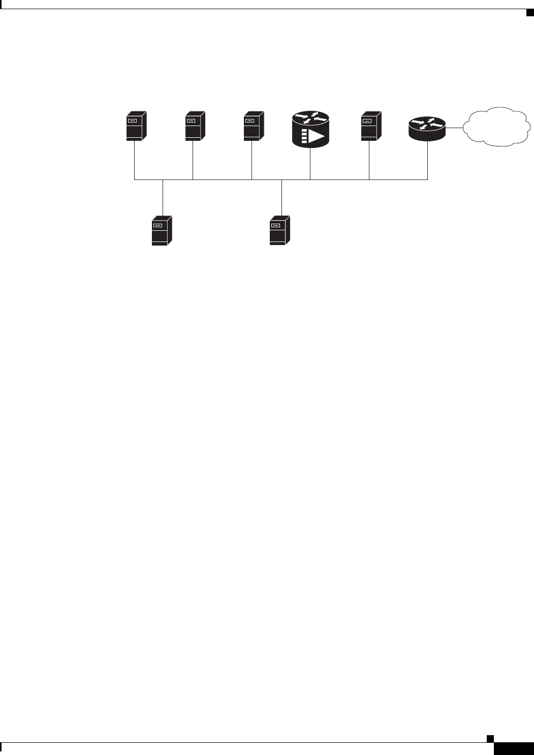
2-13
Cisco uBR7225VXR Universal Broadband Router Hardware Installation Guide
OL-17309-02
Chapter 2 Preparing the Cisco uBR7225VXR Router for Installation
Provisioning the Cable Headend
Figure 2-2 Servers on an HFC Network
Authentication, Authorization, and Accounting Servers
Authentication, authorization, and accounting (AAA) servers are essential to the network, because they
typically monitor usage for subscriber billing and record keeping. AAA features call upon a RADIUS
security server to help authenticate and monitor users’ access.
VoIP Gateways and Gatekeepers
To support digitized voice transmission on uBR7225VXR router using Cisco IOS Release 12.2(33)SCA
CMTS images, be sure to include VoIP gateways and gatekeepers in your configuration. Cisco IOS
Release 12.2(33)SCA supports VoIP by using the H.323 protocol. VoIP gateways convert IP-based voice
packets into standard PSTN voice traffic, making the process of placing calls over the IP network
transparent to users.
VoIP gatekeepers manage H.323-compliant gateways throughout the network. Gatekeepers also manage
traffic between their local cable system networks, as well as the networks of other VoIP gatekeepers.
VoIP SGCP Pass-Through
To support digitized voice transmission using Simple Gateway Control Protocol (SGCP), be sure to
include VoIP gateways and external call control elements (often referred to as call-agents) in your
configuration. Cisco IOS Release 12.2(33)SCA and later versions support VoIP communication using
the SGCP 1.1 protocol on uBR7225VXR. Just as with H.323 systems, VoIP gateways in an SGCP
environment convert IP-based voice packets into standard PSTN voice traffic, making the process of
placing calls over the IP network transparent to users.
Call-agents manage SGCP-compliant gateways throughout the network, allowing them to engage in
common channel signaling (CCS) over a 64-kbps circuit emulation service (CES) circuit.
Time-of-day
server
271657
Internet
TFTP
server
Cisco Network
Registrar
DHCP/DNS server
Cisco 7500
series router
Cisco
uBR7225VXR
Remote
access serve
r*
Log
server
(optional)
S
ecurity
server
(optional)
*A remote access server is required on an HFC network only
when you want to offer VoIP using H.323 or telco return service.

2-14
Cisco uBR7225VXR Universal Broadband Router Hardware Installation Guide
OL-17309-02
Chapter 2 Preparing the Cisco uBR7225VXR Router for Installation
Provisioning the Cable Headend
Headend Wiring
This section provides guidelines for setting up the headend wiring and cabling at your site. When
planning the location of the new system, consider the distance limitations for signaling, EMI, and
connector compatibility, as described in the following sections.
Interference Considerations
When wires are run for any significant distance in an electromagnetic field, interference can occur
between the field and the signals on the wires. This fact has two implications for the construction of
headend wiring:
•Bad wiring practice can result in radio interference emanating from the wiring, ingress noise,
co-channel interference, and degraded or erratic universal broadband router performance.
•Strong EMI, especially when caused by lightning or radio transmitters, can destroy the signal drivers
and receivers in the Cisco uBR7225VXR router, and can even create an electrical hazard by
conducting power surges through lines and into equipment. (Review the safety warnings in the
“Safety with Electricity” section on page 2-3.)
If you use twisted-pair cable in your headend wiring with a good distribution of grounding conductors,
the wiring is unlikely to emit radio interference. If you exceed the recommended distances, use a
high-quality twisted-pair cable with one ground conductor for each data signal when applicable.
If wires exceed recommended distances, or if wires pass between buildings, give special consideration
to the effect of a lightning strike in your vicinity. The electromagnetic pulse caused by lightning or other
high-energy phenomena can easily couple enough energy into unshielded conductors to destroy
electronic devices. If you have had EMI problems in the past, you might want to consult experts in
electrical surge suppression and shielding.
Distance Limitations and Interface Specifications
The size of your networks and the distances between connections depend on the type of signal, the signal
speed, and the transmission media (the type of cabling used to transmit the signals). For example,
standard coaxial cable has a greater channel capacity than twisted-pair cabling. The distance and rate
limits are the IEEE-recommended maximum speeds and distances for signaling; however, you can
usually get good results at speeds and distances far greater than these. For example, the recommended
maximum rate for V.35 is 2 Mbps, and it is commonly used at 4 Mbps without any problems. If you
understand the electrical problems that might arise and can compensate for them, you should get good
results with rates and distances greater than those recommended by IEEE; however, do so at your own
risk.
Note We recommend that you do not exceed specified transmission rate and distance limits.
When preparing your site for network connections to the Cisco uBR7225VXR router, you must consider
a number of factors related to each type of interface:
•The type of cabling required for each type of interface (fiber, thick or thin coaxial, shielded
twisted-pair, or unshielded twisted-pair cabling)
•Distance limitations for each signal type
•The specific cables you need to connect each interface

2-15
Cisco uBR7225VXR Universal Broadband Router Hardware Installation Guide
OL-17309-02
Chapter 2 Preparing the Cisco uBR7225VXR Router for Installation
Provisioning the Cable Headend
•Any additional interface equipment you need, such as transceivers, hubs, switches, modems,
channel service units (CSUs), or data service units (DSUs)
•Cable pinouts if you plan to build your cables
Before installing the Cisco uBR7225VXR router, have all additional external equipment and cables
available. The information listed above is available at Cisco.com. For ordering information, contact a
customer service representative.
Equipment Racks
The rack-mounting hardware included with the Cisco uBR7225VXR universal broadband router is
suitable for most 19-inch equipment racks and telco-type racks. To easily access field-replaceable units
(FRUs) while the router is installed in a rack, ensure that you have access to the front and rear of the
router.
Before using a particular rack, check for obstructions (such as a power strip) that could impair
rack-mount installation. If a power strip impairs a rear rack-mount installation, remove the power strip
before installing the Cisco uBR7225VXR router in the rack, then replace it after the chassis is installed.
As an alternative, you can mount the Cisco uBR7225VXR router on an equipment shelf if the rack
dimensions allow you to secure the router to the shelf, and the overall configuration permits safe
installation and access. However, we recommend rack-mounting the Cisco uBR7225VXR router.
Figure 2-3 on page 2-16 shows the Cisco uBR7225VXR router footprint and outer dimensions.
When rack-mounting the Cisco uBR7225VXR router, consider the following information:
•To mount the router between two posts or rails using the brackets, the inner clearance (the width
between the inner sides of the two posts or rails) must be at least 17.5 inches (44.45 cm).
•The height of the Cisco uBR7225VXR chassis is 3.5 inches (8.89 cm).
•When mounting the router in four-post or telco-type racks, be sure to use all the screws and the
brackets provided to secure the chassis to the rack posts.
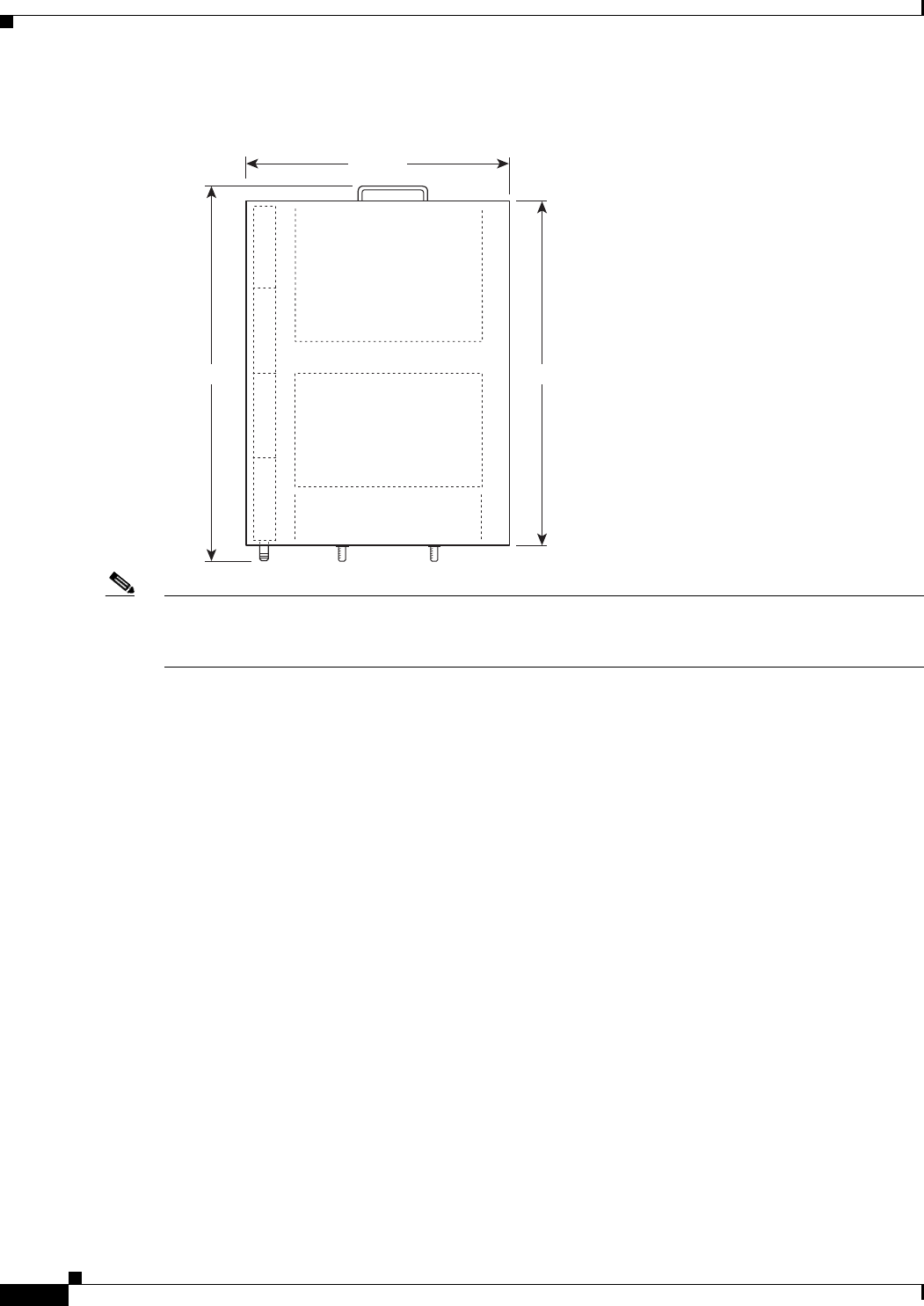
2-16
Cisco uBR7225VXR Universal Broadband Router Hardware Installation Guide
OL-17309-02
Chapter 2 Preparing the Cisco uBR7225VXR Router for Installation
Provisioning the Cable Headend
Figure 2-3 Cisco uBR7225VXR Router Footprint and Outer Dimensions (View from Top Looking
Down)
Note We recommend the rear bracket mounting system for four-post racks because this method enables you
to keep cables from protruding too far out in front of the Cisco uBR7225VXR router, and simultaneously
manage the cables at the front of the chassis with the cable-management bracket.
When planning your rack installation, consider the following information:
•Install the Cisco uBR7225VXR router in an open rack whenever possible. If installation in an
enclosed rack is unavoidable, ensure that the rack has adequate ventilation.
•If you plan to use an equipment shelf, ensure that the shelf is constructed to support the weight and
dimensions of the chassis. Figure 2-3 shows the chassis footprint, which you will need if you are
designing a customized shelf. We recommend that you use the rack-mount kit for the
Cisco uBR7225VXR router (product number ACS-uBR7225-RMK=).
•Allow sufficient clearance around the rack for maintenance. If the rack is mobile, you can push it
back near a wall or cabinet for normal operation and pull it out for maintenance (connecting cables,
or replacing or upgrading components). Otherwise, allow at least 23.25 inches (59.06 cm) of
clearance at the front, and 19 inches (48.3 cm) at the back to remove any of the field-replaceable
units.
•Maintain a minimum clearance of 3 inches (7.72 cm) on the right and left of the chassis for the
cooling air inlet and exhaust ports, respectively. Avoid placing the Cisco uBR7225VXR router in an
overly congested rack or directly next to another equipment rack; otherwise, the heated exhaust air
from other equipment can enter the inlet air vents and cause an overtemperature condition inside the
router.
•Always install heavier equipment in the lower half of a rack to maintain a low center of gravity and
prevent the rack from falling.
•If you use telco-type racks, be sure that the rack is bolted to the floor and secured, because in these
types of installations, only one end of the chassis mounts to the two rack posts with the brackets.
Ensure that the weight of the chassis does not make the rack unstable.
271658
21.875 in.
23.875 in.
17.32 in.

2-17
Cisco uBR7225VXR Universal Broadband Router Hardware Installation Guide
OL-17309-02
Chapter 2 Preparing the Cisco uBR7225VXR Router for Installation
Site Preparation Checklist
•Install and use the cable-management bracket included with the Cisco uBR7225VXR rack-mount
kit to keep cables organized. Consider the equipment and cabling that is already installed in the rack.
Ensure that cables from other equipment will not impair access to the interface slots, or require you
to disconnect cables unnecessarily to perform equipment maintenance or upgrades.
In addition to the preceding guidelines, review the precautions for avoiding overtemperature conditions
in the “Site Environment” section on page 2-5. To properly install the Cisco uBR7225VXR router
chassis in a rack, refer to the instructions in the “Cisco uBR7225VXR Router Chassis Rack-Mounting
Options” section on page 3-2.
Caution Do not install the Cisco uBR7225VXR chassis in an enclosed rack or room that is not properly ventilated
or air-conditioned. The Cisco uBR7225VXR chassis overheats if the input air temperature reaches 105oF
(41oC).
Site Preparation Checklist
Before installing the Cisco uBR7225VXR router, assemble the equipment needed to support your
network configuration and subscriber service offering. Ensure all power and cabling requirements are
met based on the equipment to be installed. Also ensure that environmental conditions are met to
maintain proper equipment operation.
Table 2-2 is a checklist that identifies the key tasks to complete.
Table 2-2 Site Preparation Checklist
Task Verified By Date
General:
Safety recommendations and guidelines reviewed.
Required general CMTS preparations completed.
Site power voltages verified.
Site environmental specifications verified.
Downstream and upstream channel plans created.
Cable plant balanced, swept and verified to comply with DOCSIS or EuroDOCSIS
recommendations.
Optical receivers adjusted for proper upstream RF output levels.
Required passwords, IP addresses, device names available.
All additional CMTS equipment to support Internet access services, RF-related
equipment, servers and other host computers, a Cisco uBR900 series cable access router,
and console accessory kit to test operation of your network available.
Required tools and cables available.
Telco Return Configurations:
Telco return dial-up plan created.
Network access server installed and configured.
Telephone circuits, connections, and all equipment to support telco return available.
IP Telephony Configurations:

2-18
Cisco uBR7225VXR Universal Broadband Router Hardware Installation Guide
OL-17309-02
Chapter 2 Preparing the Cisco uBR7225VXR Router for Installation
Component Checklists
Component Checklists
•Check off the equipment as it is unpacked.
•Titles and quantities of documents will vary.
Table 2-3 provides the list to verify the contents of the shipping container for the Cisco uBR7225VXR
router.
Gatekeeper and gateway equipment installed and configured.
Dial plan based on the supported VoIP protocol used—H.323 or SGCP.
Table 2-2 Site Preparation Checklist (continued)
Task Verified By Date
Table 2-3 Cisco uBR7225VXR Router Component List
Description Received
•Cisco uBR7225VXR chassis
•Network processing engine
•Up to two AC-input power supplies and power cords (blank power supply filler plate should be
installed in empty power supply slot)
•Up to two cable interface line cards (blank cable interface line cards should be installed in empty
cable interface line card slots)
•CompactFlash Disk
The following accessories might arrive in separate shipping containers:
•Rack-mount and cable-management kit—Two rack-mount brackets, cable-management bracket,
eight M4 x 6-mm Phillips flathead screws, four M3 x 6-mm Phillips panhead screws, and four
10/32 x 3/8-inch slotted binderhead screws
•AC-input power cables—Up to two AC-input power cables (if separate AC-input power supply
ordered)
•Documentation, including the following:
–
Cisco Information Packet
–
Cisco Network Registrar documentation—if ordered
–
Cisco IOS software documentation set—if ordered
Note All hardware and software documentation is also found at the following URL:
http://www.cisco.com/en/US/products/hw/cable/ps2217/tsd_products_support_series_home.ht
ml

CHAPTER
3-1
Cisco uBR7225VXR Universal Broadband Router Hardware Installation Guide
OL-17309-02
3
Installing the Cisco uBR7225VXR Router
This chapter explains how to install and connect a Cisco uBR7225VXR universal broadband router and
contains the following sections:
•Cisco uBR7225VXR Router Installation Checklist, page 3-1
•Cisco uBR7225VXR Router Chassis Rack-Mounting Options, page 3-2
•Installing the Brackets on the Chassis, page 3-7
•Installing the Chassis in a Workbench or Tabletop Environment, page 3-12
•Cabling, page 3-13
•Console and Auxiliary Port Connection Equipment, page 3-14
•Protective Grounding, page 3-16
•Connecting Power, page 3-16
•Powering On the Cisco uBR7225VXR Router, page 3-18
Cisco uBR7225VXR Router Installation Checklist
A rack-mount and cable-management kit is included in the shipping container. The rack-mount brackets
in the kit are for mounting the Cisco uBR7225VXR in standard, 19-inch-wide, 4-post equipment racks
or telco-type equipment racks. The rack-mount brackets are not suitable for use with other racks, such
as 23-inch telco racks. The cable-management bracket is designed to relieve the strain on interface cables
that are installed on cable interface line cards in a Cisco uBR7225VXR router.
If you are installing an equipment shelf or using mounting hardware other than that supplied with the
chassis, review the guidelines in the “Equipment Racks” section on page 2-15, then proceed to the
“Cisco uBR7225VXR Router Chassis Rack-Mounting Options” section on page 3-2.
If you do not plan to install your Cisco uBR7225VXR router in an equipment rack, proceed to the
“Installing the Chassis in a Workbench or Tabletop Environment” section on page 3-12.
To assist you with your installation and to provide a historical record of what was done, and by whom,
use “Cisco uBR7225VXR Router Installation Checklist” section on page 2. Make a copy of this
checklist and indicate when each procedure or verification is completed. When the checklist is
completed, place it in your site log (see Appendix G, “Site Log”) along with the other records for your
new router.

3-2
Cisco uBR7225VXR Universal Broadband Router Hardware Installation Guide
OL-17309-02
Chapter 3 Installing the Cisco uBR7225VXR Router
Cisco uBR7225VXR Router Chassis Rack-Mounting Options
Cisco uBR7225VXR Router Chassis Rack-Mounting Options
The chassis mounts to two rack posts with brackets that attach to either the front, middle, or rear sides
of the chassis. The inside width between the posts or mounting strips (left and right) must be at least
17.5 inches (44.45 cm).
Some equipment racks provide a power strip along the length of one of the mounting strips. Figure 3-1
shows a typical 4-post equipment rack with a power strip along one of the back posts. If your rack has
this feature, consider the position of the strip when planning fastener points and ensure that you will be
able to pull cable interface line card cables and other FRUs straight out of their respective slots.
The inlet and exhaust ports for cooling air are located on the right and left of the chassis, respectively,
so multiple universal broadband routers can be stacked in a rack with little or no vertical clearance.
Note We recommend the rear bracket mounting system for 4-post racks. This method enables you to keep
cables from protruding too far out in front of the Cisco uBR7225VXR router and to simultaneously
manage the cables at the front of the chassis with the cable-management bracket.
Table 3-1 Cisco uBR7225VXR Router Installation Checklist
Task Verified by Date
Router and all accessories unpacked
Types and numbers of interfaces verified
Verify shipping container contents see the “Shipping Container Contents” section
on page 2-9
Router mounted in rack (optional)
Cable-management bracket installed (optional but recommended)
Chassis properly grounded
AC power cables connected to power sources and router; cables secured
Captive installation screws on network processing engine checked
Network interface cables and devices connected
ASCII terminal attached to console port
Console port set for 9600 baud, 8 data bits, no parity, and 1 stop bit (9600 8N1)
System power turned on (Input OK LED is on)
System boot complete
Network processing engine and all cable interface line cards operational
System ready for global and interface-specific configuration
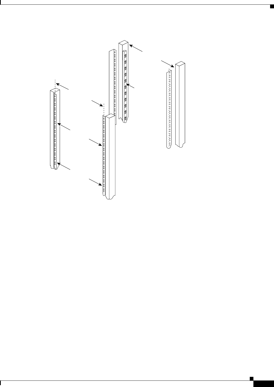
3-3
Cisco uBR7225VXR Universal Broadband Router Hardware Installation Guide
OL-17309-02
Chapter 3 Installing the Cisco uBR7225VXR Router
Cisco uBR7225VXR Router Chassis Rack-Mounting Options
Figure 3-1 Typical 4-Post Equipment Rack Posts and Mounting Strips
Mounting options are as follows:
•If you want the cable interface line card end (the front) of the chassis recessed in the rack, install
the rack-mount brackets at the rear of the chassis in the orientation shown in Figure 3-2 on page 3-4.
•If you want the front of the chassis mounted flush with the front posts of the rack, install the
rack-mount brackets at the front of the chassis in the orientation shown in Figure 3-3 on page 3-4.
•If you want the front of the chassis protruding out of the rack, install the rack-mount brackets at the
front of the chassis in the orientation shown in Figure 3-4 on page 3-5.
•If you want the chassis in a telco-type rack, install the rack-mount brackets in the middle of the
chassis in the orientation shown in Figure 3-5 on page 3-5.
18.31 in.
(46.48 cm)
hole
center-to-center
17.5 in.
(44.45 cm)
min.
Rack posts
Mounting strips
110 VAC
outlets
10327
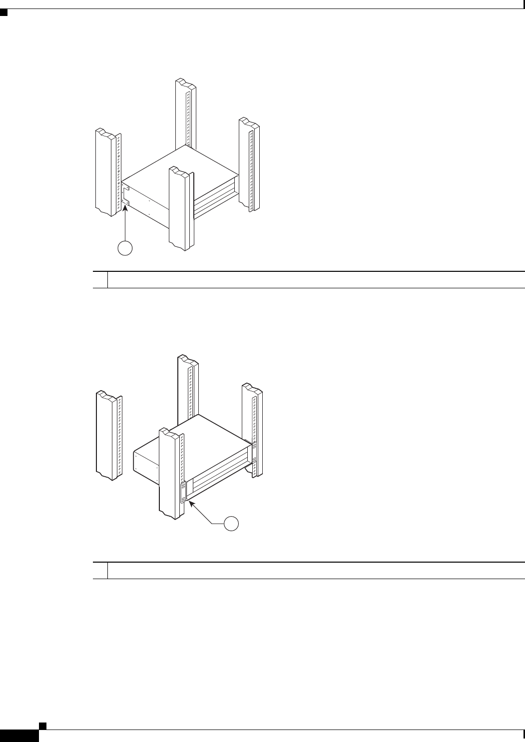
3-4
Cisco uBR7225VXR Universal Broadband Router Hardware Installation Guide
OL-17309-02
Chapter 3 Installing the Cisco uBR7225VXR Router
Cisco uBR7225VXR Router Chassis Rack-Mounting Options
Figure 3-2 Installing the Chassis in a 4-Post Rack—Rear Installation
See the “Installing Rack-Mount Brackets on the Rear of the Chassis” section on page 3-7.
Figure 3-3 Installing the Chassis in a 4-Post Rack—Flush-Mounted Front Installation
See the “Installing Rack-Mount Brackets on the Front of the Chassis” section on page 3-8 for bracket
mounting information.
1Rack-mount bracket
271659
1
271660
1
1Rack-mount bracket

3-5
Cisco uBR7225VXR Universal Broadband Router Hardware Installation Guide
OL-17309-02
Chapter 3 Installing the Cisco uBR7225VXR Router
Cisco uBR7225VXR Router Chassis Rack-Mounting Options
Figure 3-4 Installing the Chassis in a 4-Post Rack—Chassis Protruding Front Installation
See the “Installing Rack-Mount Brackets in the Middle of the Chassis” section on page 3-9 for bracket
mounting information.
Figure 3-5 Installing the Chassis in a Telco-Type Rack
Cable-Management Bracket Requirements
There are two cable-management bracket configurations available for rack-mounting the
Cisco uBR7225VXR router. In the first configuration, for a 4-post rack, the rack-mount brackets are
installed at the rear of the chassis and the cable-management bracket is installed at the right front of the
chassis. (See Figure 3-6.) You must install both sets of brackets before you install the chassis in the rack.
271661
1
1Rack-mount bracket
271662
1
1Rack-mount bracket
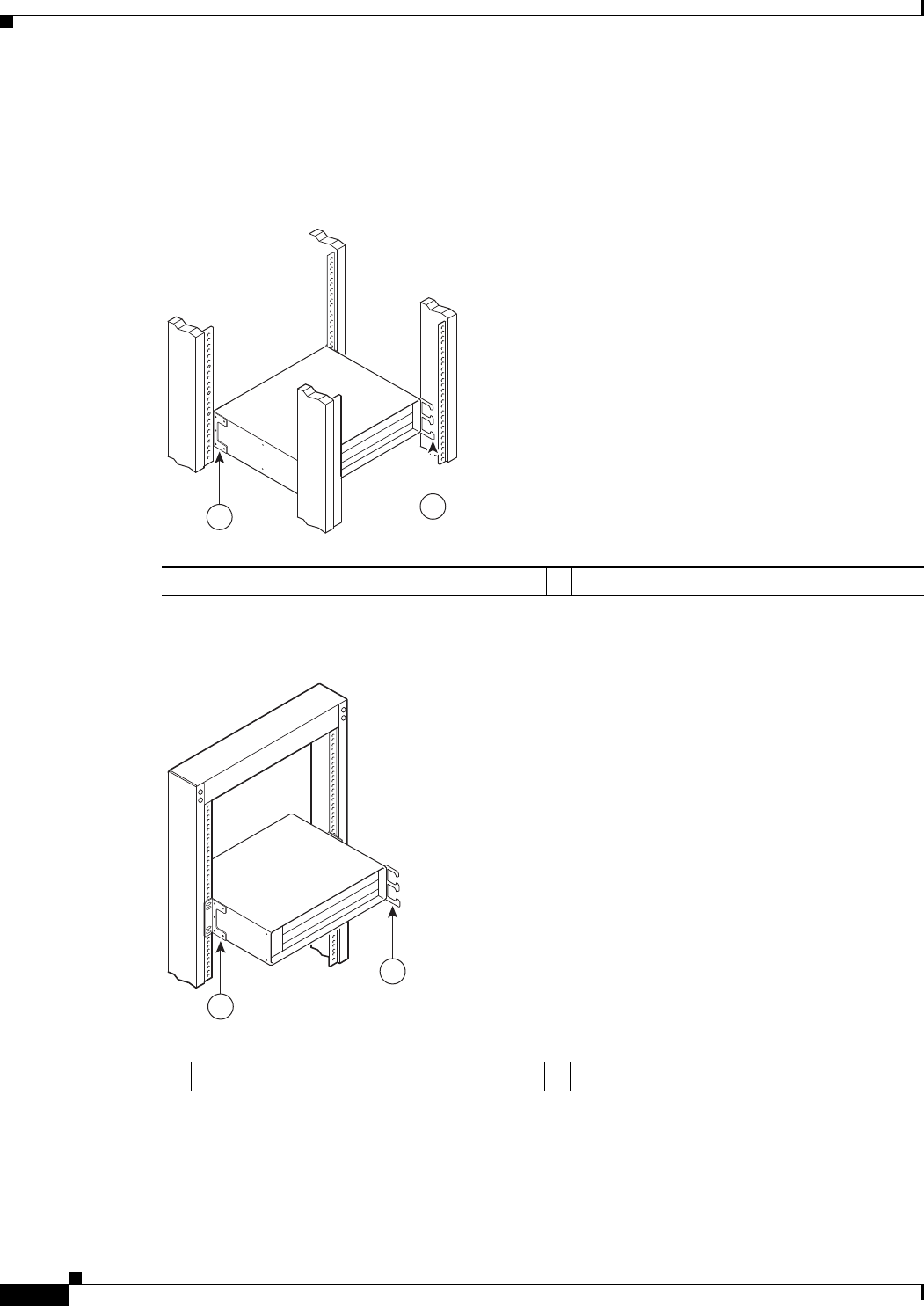
3-6
Cisco uBR7225VXR Universal Broadband Router Hardware Installation Guide
OL-17309-02
Chapter 3 Installing the Cisco uBR7225VXR Router
Cisco uBR7225VXR Router Chassis Rack-Mounting Options
In the second configuration, for a telco-type rack, the rack-mount brackets are installed at the middle of
the chassis and the cable-management bracket is installed at the right front of the chassis. (See
Figure 3-7.) You must install both sets of brackets before you install the chassis in the rack.
Figure 3-6 Installing the Chassis in a 4-Post Rack with an Installed Cable-Management Bracket
Figure 3-7 Installing the Chassis in a Telco-Type Rack with an Installed Cable-Management
Bracket
1Rack-mount bracket 2Cable-management bracket
271663
12
1Rack-mount bracket 2Cable-management bracket
271664
1
2

3-7
Cisco uBR7225VXR Universal Broadband Router Hardware Installation Guide
OL-17309-02
Chapter 3 Installing the Cisco uBR7225VXR Router
Installing the Brackets on the Chassis
Installing the Brackets on the Chassis
This section explains how to install the rack-mount brackets and cable-management bracket on a
Cisco uBR7225VXR universal broadband router. Before installing the chassis in the rack, you must
install cable-management bracket and a rack-mount bracket on each side of the front, middle, or rear of
the chassis.
The parts and tools required for installing the rack-mount and cable-management bracket are listed in
the “Installation Tools” section on page 2-8.
Installing Rack-Mount Brackets on the Rear of the Chassis
To install the rack-mount brackets and cable-management bracket on the chassis for a rear rack-mount
configuration, complete the following steps:
Step 1 Locate the threaded holes in the rear sides of the chassis.
Step 2 Align the first rack-mount bracket to the threaded holes in the right side of the chassis. See Figure 3-8.
Figure 3-8 Installing the Rack-Mount Brackets on the Rear of the Chassis
Note There are five holes in each of the rack-mount brackets for the Cisco uBR7225VXR router. Four holes
are used for front and middle mount, and five holes are used for rear mount.
Step 3 Thread five M4 x 6-mm Phillips flathead screws through the rack-mount bracket and into the side of the
chassis. Use a number 2 Phillips screwdriver to tighten the screws.
Step 4 Repeat Step 1 through Step 3 for the other rack-mount bracket.
Step 5 If you plan to include the cable-management bracket in your rear rack-mount configuration, align the
bracket with the two right front-side holes.
1Rack-mount bracket
271665
1
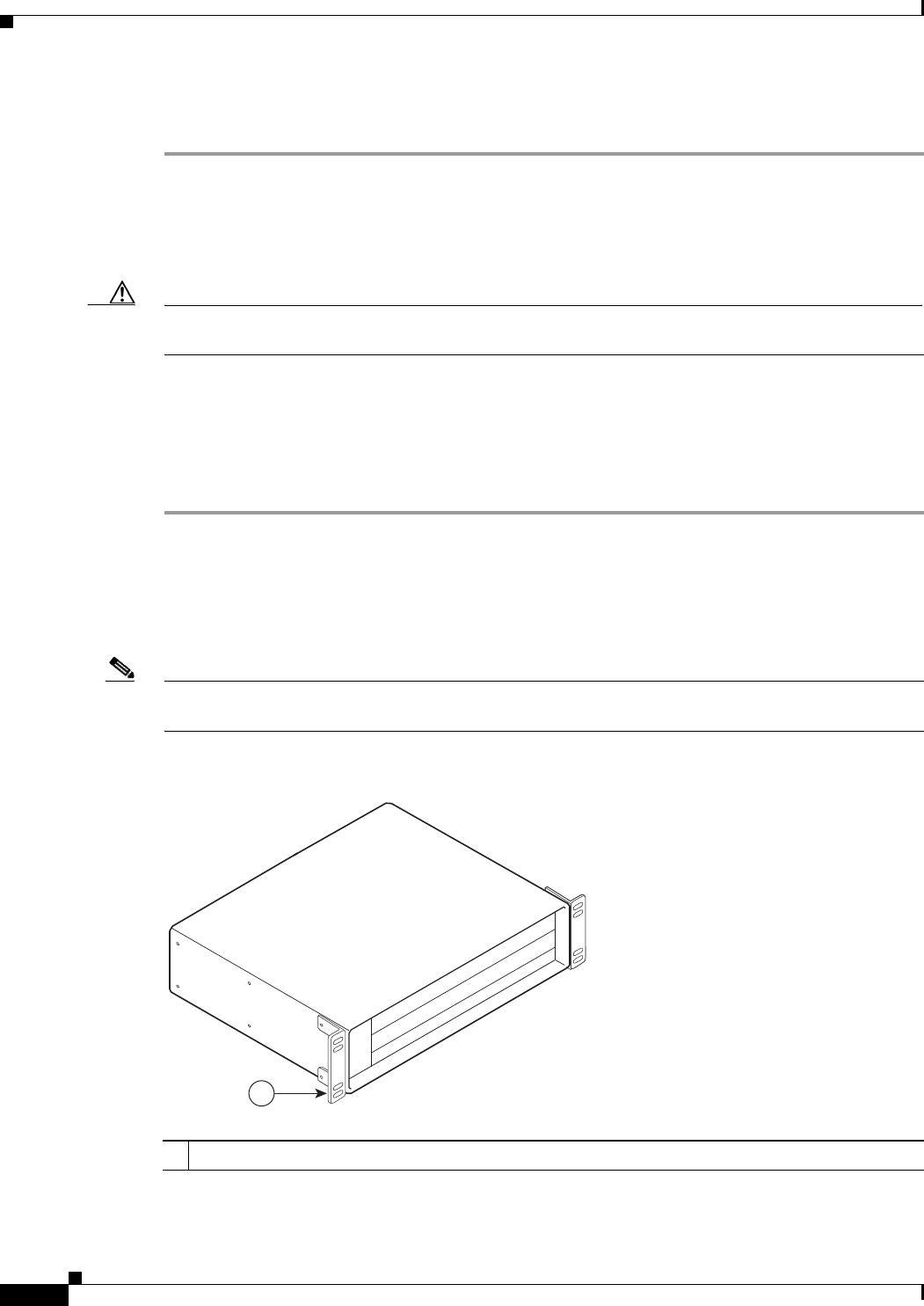
3-8
Cisco uBR7225VXR Universal Broadband Router Hardware Installation Guide
OL-17309-02
Chapter 3 Installing the Cisco uBR7225VXR Router
Installing the Brackets on the Chassis
Step 6 Thread two M3 x 6-mm Phillips panhead screws through the cable-management bracket and into the
chassis, and tighten the screws.
This completes the procedure for installing the rack-mount brackets and the cable-management bracket
on the chassis for a rear rack-mount configuration. Proceed to the “Installing the Chassis in the Rack”
section on page 3-10.
Caution To prevent injury, review the safety precautions in Chapter 2, “Preparing the Cisco uBR7225VXR
Router for Installation,” before installing the Cisco uBR7225VXR router in a rack.
Installing Rack-Mount Brackets on the Front of the Chassis
To install the rack-mount brackets and cable-management bracket on the chassis for a front rack-mount
configuration, complete the following steps:
Step 1 Locate the threaded holes in the front sides of the chassis.
Step 2 If you want the front of the chassis flush with the front of the rack, align the first rack-mount bracket to
the threaded holes in the right side of the chassis as shown in Figure 3-9 on page 3-8.
If you want the front of the chassis protruding from the rack, align the first rack-mount bracket to the
threaded holes in the right side of the chassis as shown in Figure 3-10 on page 3-9.
Note There are five holes in each of the rack-mount brackets for the Cisco uBR7225VXR. Four holes are used
for front and middle mount, and five holes are used for rear mount.
Figure 3-9 Installing the Rack-Mount Brackets so the Front of the Chassis Is Flush with the Rack
1Rack-mount bracket
271666
1
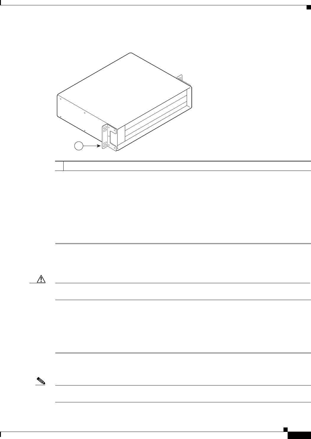
3-9
Cisco uBR7225VXR Universal Broadband Router Hardware Installation Guide
OL-17309-02
Chapter 3 Installing the Cisco uBR7225VXR Router
Installing the Brackets on the Chassis
Figure 3-10 Installing the Rack-Mount Brackets so the Front of the Chassis Protrudes Out of the
Rack
Step 3 Thread four M4 x 6-mm Phillips flathead screws through the rack-mount bracket and into the side of the
chassis. Use a number 2 Phillips screwdriver to tighten the screws.
Step 4 Repeat Step 1 through Step 3 for the other rack-mount bracket.
Step 5 If you plan to include the cable-management bracket in your front rack-mount configuration, align the
bracket with the two right front-side holes.
Step 6 Thread two M3 x 6-mm Phillips panhead screws through the cable-management bracket and into the
chassis, and tighten the screws.
This completes the procedure for installing the rack-mount brackets on the chassis for a front rack-mount
configuration. Proceed to the “Installing the Chassis in the Rack” section on page 3-10.
Caution To prevent injury, review the safety precautions in Chapter 2, “Preparing the Cisco uBR7225VXR
Router for Installation,” before installing the universal broadband router in a rack.
Installing Rack-Mount Brackets in the Middle of the Chassis
To install the rack-mount brackets and cable-management bracket at the middle of the chassis for a
telco-type rack-mount configuration, complete the following steps:
Step 1 Locate the threaded holes in the middle sides of the chassis.
Step 2 Align the first rack-mount bracket to the threaded holes in the right side of the chassis. See Figure 3-11.
Note There are five holes in each of the rack-mount brackets for the Cisco uBR7225VXR router. Four holes
are used for front and middle mount, and five holes are used for rear mount.
1Rack-mount bracket
271667
1
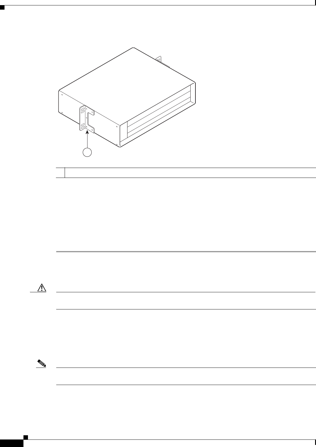
3-10
Cisco uBR7225VXR Universal Broadband Router Hardware Installation Guide
OL-17309-02
Chapter 3 Installing the Cisco uBR7225VXR Router
Installing the Brackets on the Chassis
Figure 3-11 Installing the Rack-Mount Brackets in the Middle of the Chassis for Telco-Type Racks
Step 3 Thread four M4 x 6-mm Phillips flathead screws through the rack-mount bracket and into the side of the
chassis. Use a number 2 Phillips screwdriver to tighten the screws.
Step 4 Repeat Step 1 through Step 3 for the other rack-mount bracket.
Step 5 If you plan to include the cable-management bracket in your telco-type rack-mount configuration, align
the bracket with the right front-side holes.
Step 6 Thread two M3 x 6-mm Phillips panhead screws through the cable-management bracket and into the
chassis, and tighten the screws.
This completes the procedure for installing the rack-mount brackets and cable-management bracket on
the Cisco uBR7225VXR router. Proceed to the following section, “Installing the Chassis in the Rack.”
Caution To prevent injury, review the safety precautions in Chapter 2, “Preparing the Cisco uBR7225VXR
Router for Installation,” before installing the Cisco uBR7225VXR router in a rack.
Installing the Chassis in the Rack
After installing the brackets on the chassis, mount the chassis by securing the rack-mount brackets to the
posts or mounting strips in the rack using the slotted screws provided.
Note When installing the uBR7225VXR in a rack, ensure that paint is removed from the rack and an
anti-oxidant is applied at the contact points to ensure reliable metal to metal contact.
1Rack-mount bracket
271668
1

3-11
Cisco uBR7225VXR Universal Broadband Router Hardware Installation Guide
OL-17309-02
Chapter 3 Installing the Cisco uBR7225VXR Router
Installing the Brackets on the Chassis
Caution Because the brackets support the weight of the entire chassis, be sure to use all of the required slotted
screws to fasten the two rack-mount brackets to the rack posts. Figure 3-2 on page 3-4, Figure 3-3 on
page 3-4, Figure 3-4 on page 3-5, and Figure 3-5 on page 3-5 show typical installations in 19-inch,
four-post and telco-type equipment racks.
Warning
Two people are required to lift the chassis. Grasp the chassis underneath the lower edge and lift with
both hands. To prevent injury, keep your back straight and lift with your legs, not your back. To prevent
damage to the chassis and components, never attempt to lift the chassis with the handles on the
power supplies or on the interface processors, or by the plastic panels on the front of the chassis.
These handles were not designed to support the weight of the chassis.
Statement 5
To install the chassis in the rack, complete the following steps:
Step 1 On the chassis, ensure that all captive installation screws on the network processing engine, each
cable interface line card, and each power supply are tightened.
Step 2 Make sure that your path to the rack is unobstructed. If the rack is on wheels, ensure that the brakes are
engaged or that the rack is otherwise stabilized.
Caution Two people should perform Step 3 through Step 6.
Step 3 Position the chassis so that the front end is closest to you; then lift the chassis and move it to the rack.
To prevent injury, avoid sudden twists or moves.
Step 4 Slide the chassis into the rack, pushing it back until the brackets (installed at the front or rear of the
chassis) meet the mounting strips or posts on both sides of the equipment rack.
Note The rack-mount bracket must be placed behind the rack post or mounting strip in the rear installation
configuration. (See Figure 3-2 on page 3-4.)
Step 5 While keeping the brackets flush against the posts or mounting strips, position the router so that the holes
in the brackets are aligned with those in the mounting strips.
Warning
To prevent bodily injury when mounting or servicing this unit in a rack, you must take special
precautions to ensure that the system remains stable. The following guidelines are provided to
ensure your safety:
Statement 1006
•This unit should be mounted at the bottom of the rack if it is the only unit in the rack.
•When mounting this unit in a partially filled rack, load the rack from the bottom to the top with
the heaviest component at the bottom of the rack.
•If the rack is provided with stabilizing devices, install the stabilizers before mounting or servicing
the unit in the rack.

3-12
Cisco uBR7225VXR Universal Broadband Router Hardware Installation Guide
OL-17309-02
Chapter 3 Installing the Cisco uBR7225VXR Router
Installing the Chassis in a Workbench or Tabletop Environment
Step 6 Insert the 10/32 x 3/8 slotted screws (two to a side) through the brackets and into the mounting strip (use
the top and bottom bracket holes, shown in Figure 3-2 on page 3-4, Figure 3-3 on page 3-4, Figure 3-4
on page 3-5, and Figure 3-5 on page 3-5). Using a 7/16-inch flat-blade screwdriver, tighten all the
screws.
This completes the procedure for installing the chassis in the rack. Proceed to the “Cabling” section on
page 3-13 to continue the installation.
Installing the Chassis in a Workbench or Tabletop Environment
The Cisco uBR7225VXR universal broadband router should already be in the area where you will install
it, and your installation location should already be determined. If not, refer to the “Site Requirements”
section on page 2-5.
When installing the router on a workbench or tabletop, ensure that the surface is clean and in a safe
location and that you have considered the following:
•The Cisco uBR7225VXR router requires at least 3 inches (7.72 cm) of clearance at the inlet and
exhaust vents (the right and left sides of the router).
•The Cisco uBR7225VXR router should be installed off the floor. (Dust that accumulates on the floor
can be drawn into the interior of the router by the cooling fans. Excessive dust inside the router can
cause overtemperature conditions and component failures.)
•There must be approximately 23.25 inches (59.06 cm) of clearance at the front, and 19 inches
(48.3 cm) at the back of the Cisco uBR7225VXR router for installing and replacing
field-replaceable units (FRUs), or accessing network cables or equipment.
•Make sure that blank cable interface line card and blank power supply filler plates are installed in
empty slots.
•The Cisco uBR7225VXR router will receive adequate ventilation (it is being installed in an enclosed
cabinet where ventilation is adequate).
•If you plan to install the cable-management bracket on the front of the chassis, set aside the
cable-management bracket and the four M3 x 6-mm Phillips panhead screws.
Warning
Do not stack the chassis on any other equipment. If the chassis falls, it can cause severe bodily injury
and equipment damage.
Statement 48
Complete the following steps to install the Cisco uBR7225VXR router on a workbench or tabletop:
Step 1 Remove any debris and dust from the tabletop or workbench, and the surrounding area. Also make sure
that your path between the router and its new location is unobstructed.
Step 2 On the chassis, ensure that all captive installation screws on the network processing engine, cable
interface line cards, and each power supply are tightened.
Warning
Two people are required to lift the chassis. To prevent injury, keep your back straight and lift with your
legs, not your back.
Statement 164

3-13
Cisco uBR7225VXR Universal Broadband Router Hardware Installation Guide
OL-17309-02
Chapter 3 Installing the Cisco uBR7225VXR Router
Cabling
Step 3 Add the five rubber feet supplied with the accessory kit to the base of the chassis. Five indented circles
are provided on the base of the chassis to indicate the location to which the rubber feet can be added.
Step 4 Place the Cisco uBR7225VXR router on the tabletop or workbench.
Step 5 Ensure that there is the appropriate amount of space around the router.
If you want to install a cable-management bracket on the Cisco uBR7225VXR router, proceed to the
following section, “Installing the Cable-Management Bracket on a Cisco uBR7225VXR Router in a
Workbench or Tabletop Environment.” Otherwise, proceed to the “Cabling” section on page 3-13.
Installing the Cable-Management Bracket on a Cisco uBR7225VXR Router in a
Workbench or Tabletop Environment
To install the cable-management bracket on a Cisco uBR7225VXR universal broadband router installed
on a workbench or tabletop, complete the following steps:
Step 1 Locate the threaded holes in the right front side of the chassis.
Step 2 Align the cable-management bracket with the two threaded holes on the front or rear side of the
Cisco uBR7225VXR chassis. (See Figure 3-7 on page 3-6.)
Step 3 Thread two M3 x 6-mm Phillips panhead screws through the bracket and into the chassis. Use a number
2 Phillips screwdriver to tighten the screws.
This completes the steps for installing the cable-management bracket on the Cisco uBR7225VXR router.
Proceed to, “Cabling” section on page 3-13 to continue the installation.
Cabling
This section provides information on connecting cable interface cards, auxiliary and console ports to
your Cisco uBR7225VXR universal broadband router.
Warning
This product is not intended to be directly connected to the Cable Distribution System. Additional
regulatory compliance and legal requirements may apply for direct connection to the Cable
Distribution System. This product may connect to the Cable Distribution System ONLY through a device
that is approved for direct connection.
Statement 1078
Warning
The intra-building port(s) of the equipment or subassembly is suitable for connection to intra-building
or unexposed wiring or cabling only. The intra-building port(s) of the equipment or subassembly
MUST NOT metallically connect to interfaces that connect to the OSP or its wiring. These interfaces
are designed for use as intra-building interfaces only (Type 2 or Type 4 ports as described in
GR-1089-CORE, Issue 4) and require isolation from the exposed OSP cabling. The addition of Primary
Protectors is not sufficient protection in order to connect these interfaces metallically to OSP wiring.
Statement 7005
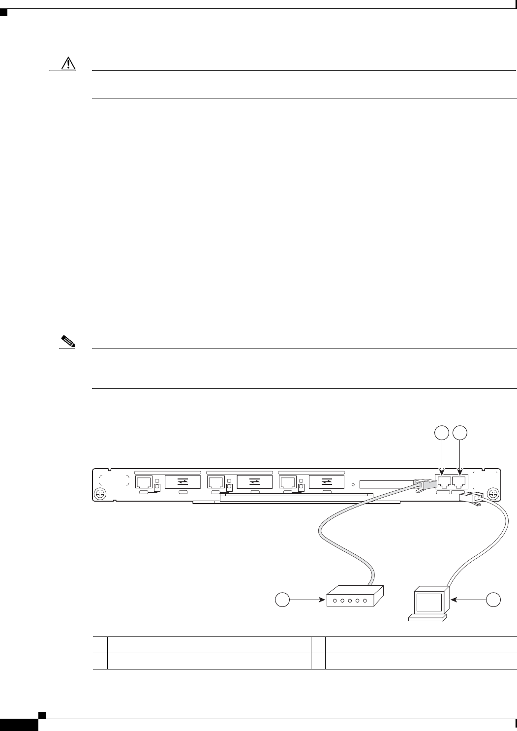
3-14
Cisco uBR7225VXR Universal Broadband Router Hardware Installation Guide
OL-17309-02
Chapter 3 Installing the Cisco uBR7225VXR Router
Console and Auxiliary Port Connection Equipment
Caution To comply with GR-1089-Core intra-building lightning-immunity requirements, you must use shielded
(screened) cable that is grounded at both ends.
Connecting Cable Interface Line Card Cables
The instructions for connecting the cables for each cable interface line card installed in the
Cisco uBR7225VXR universal broadband router are contained in the cable interface line card
installation document. Refer to the Cisco uBR7200 Series Interface Line Card Hardware Installation
Guide at the following URL:
http://www.cisco.com/en/US/docs/interfaces_modules/cable/line_cards/installation/guide/mcxxfru.htm
l
Console and Auxiliary Port Connection Equipment
The NPE contains the console and auxiliary ports. The console port is a RJ-45 receptacle for connecting
a data terminal, which you use to configure the interfaces and bring up the Cisco uBR7255VXR router.
The auxiliary port is a RJ-45 receptable for connecting a modem or the other DCE device (such as a
channel service unit/data service unit [CSU/DSU]) to the router. (See Figure 3-12 on page 3-14.)
Note Both the console and auxiliary ports are asynchronous ports; any devices connected to these ports must
be capable of asynchronous transmission. (Asynchronous is the most common type of serial device; for
example, most modems are asynchronous devices.)
Figure 3-12 Console and Auxiliary Port Connections
1Console port 3Console terminal
2Auxiliary port 4Modem
272232
4
COMPACT FLASH
GIGABIT ETHERNET 0/1
RJ45 GBIC
EN
RX TX
LINK
CONSOLE AUX
GIGABIT ETHERNET 0/1
RJ45 GBIC
EN
RX TX
LINK
GIGABIT ETHERNET 0/1
RJ45 GBIC
EN
RX TX
LINK CPU
RESET
POWER
ON
SLOT
ACTIVE
NETWORK PROCESSING ENGINE - G1
12
3

3-15
Cisco uBR7225VXR Universal Broadband Router Hardware Installation Guide
OL-17309-02
Chapter 3 Installing the Cisco uBR7225VXR Router
Console and Auxiliary Port Connection Equipment
Before connecting a terminal to the console port, configure the terminal to match the
Cisco uBR7225VXR router console port as follows:
•9600 baud
•8 data bits
•No parity
•1 stop bit (9600 8N1)
You need an RJ-45 console cable to connect the terminal to the console port. After you establish normal
universal broadband router operation, you can disconnect the terminal.
You must supply your own interface cable between the auxiliary port and the equipment you are
connecting. For console and auxiliary port pinouts, refer to the “Console Port Signals” section on
page 3-15 and the “Auxiliary Port Signals” section on page 3-15.
Console Port Signals
Both Data Set Ready (DSR) and Data Carrier Detect (DCD) signals are active when the system is
running. The Request To Send (RTS) signal tracks the state of the Clear To Send (CTS) input. The
console port does not support modem control or hardware flow control. Table 3-2 lists the signals used
on the console port. The console port requires a straight-through EIA/TIA-232 cable.
Auxiliary Port Signals
Table 3-3 lists the signals used on the auxiliary port. The auxiliary port supports hardware flow control
and modem control.
Table 3-2 Console Port Signal
Pin Signal Direction Description
1 GND – Ground
2 TxD <— Transmit Data
3 RxD —> Receive Data
6 DSR —> Data Set Ready (always on)
7 GND – Ground
8 DCD —> Data Carrier Detect (always on)
Table 3-3 Auxiliary Port Signals
Pin Signal Direction Description
2 TxD —> Transmit Data
3 RxD <— Receive Data
4 RTS —> Request To Send (used for hardware flow control)
5 CTS <— Clear To Send (used for hardware flow control)
6 DSR <— Data Set Ready
7 Signal Ground – Signal Ground

3-16
Cisco uBR7225VXR Universal Broadband Router Hardware Installation Guide
OL-17309-02
Chapter 3 Installing the Cisco uBR7225VXR Router
Protective Grounding
Protective Grounding
The building installation should provide a means for connection to the protective earth grounding. The
equipment should be connected to that means.
Note The uBR7225VXR is intended for installation in a Common Bonding Network (CBN).
While installing the equipment, the service person should check whether the power source is adequately
grounded. If it is not, the service person should arrange for the installation of a protective grounding
conductor from the equipment to the protective grounding wire in the building. This conductor should
consist of a minimum #6 American Wire Gauge (AWG) stranded copper wire. See Figure 3-13 to
identify the ground lug location.
Figure 3-13 Cisco uBR7225VXR Ground Lug Location
Connecting Power
Following are the procedures for connecting AC-input power to your Cisco uBR7225VXR universal
broadband router.
Warning
High leakage current - earth connection essential before connecting to system power supply.
Statement 342
Warning
Care must be given to connecting units to the supply circuit so that wiring is not overloaded.
Statement
1018
Warning
Read the installation instructions before you connect the system to its power source.
Statement 1004
8 CD <— Carrier Detect (used for modem control)
20 DTR —> Data Terminal Ready (used for modem control only)
Table 3-3 Auxiliary Port Signals
Pin Signal Direction Description
1Ground lug location
270534
uBR7225-VXR
uBR7225-VXR 1

3-17
Cisco uBR7225VXR Universal Broadband Router Hardware Installation Guide
OL-17309-02
Chapter 3 Installing the Cisco uBR7225VXR Router
Connecting Power
Warning
Before working on equipment that is connected to power lines, remove jewelry (including rings,
necklaces, and watches). Metal objects will heat up when connected to power and ground and can
cause serious burns or weld the metal object to the terminals.
Statement 43
Warning
This equipment is intended to be grounded to comply with emission and immunity requirements.
Ensure that the switch functional ground lug is connected to earth ground during normal use.
Statement 1064
Warning
This equipment must be grounded. Never defeat the ground conductor or operate the equipment in the
absence of a suitably installed ground conductor. Contact the appropriate electrical inspection
authority or an electrician if you are uncertain that suitable grounding is available.
Statement 1024
Note Detailed instructions for handling and replacing the Cisco uBR7225VXR router power supplies are
contained in the Cisco uBR7200 Series Universal Broadband Router AC-Input Power Supply
Replacement Instructions at the following URL:
http://www.cisco.com/en/US/docs/cable/cmts/ubr7200/installation/4848pwra.html
Connecting to the AC-Input Power Supply
Warning
The device is designed to work with TN power systems.
Statement 19
Note A certified external Surge Protective Device (SPD) is used at the AC-input of the Cisco uBR7225VXR
universal broadband router.
To connect to the AC-input power supply:
Step 1 At the rear of the Cisco uBR7225VXR universal broadband router, ensure that the power switch on the
power supply is in the off (0) position.
Step 2 Plug in the power cable.
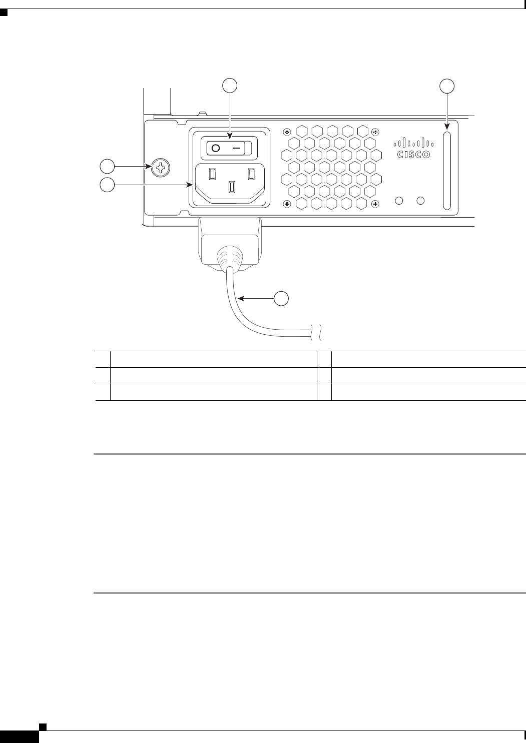
3-18
Cisco uBR7225VXR Universal Broadband Router Hardware Installation Guide
OL-17309-02
Chapter 3 Installing the Cisco uBR7225VXR Router
Powering On the Cisco uBR7225VXR Router
Figure 3-14 Connecting AC-Input Power
Step 3 Plug the AC power supply cable into the AC power source.
Step 4 Repeat Step 1 through Step 3 for the second power supply (if present).
This completes the procedure for connecting AC-input power. Proceed to the “Powering On the
Cisco uBR7225VXR Router” section on page 3-18.
Powering On the Cisco uBR7225VXR Router
After installing your Cisco uBR7225VXR universal broadband router and connecting cables, power on
the universal broadband router as follows:
Step 1 Check for the following:
•Each cable interface line card is inserted in its slot and its captive installation screws are tightened.
•The network processing engine is inserted in to its slot and the captive installation screws are
tightened.
1Power switch 4Power receptacle
2Handle 5Captive installation screw
3AC power cable
271670
PWR-UBR7225VXR-AC
100-240 VAC
4-2 A
50-60 Hz
Input
OK
Output
OK
12
5
4
3

3-19
Cisco uBR7225VXR Universal Broadband Router Hardware Installation Guide
OL-17309-02
Chapter 3 Installing the Cisco uBR7225VXR Router
Configuring the Interfaces
Note If the cable interface line card or the network processing engine is not properly seated or not fully locked
into place, the Cisco uBR7225VXR router might enter a continuous restart loop. Make sure that the
boards are seated and locked into position.
•Hybrid fiber-coaxial (HFC) network coaxial cable is connected to the cable interface line cards.
•A CompactFlash Disk is installed in a CompactFlash Disk slot in the front panel of the NPE-G1 or
NPE-G2. Use only authorized Cisco provided CompactFlash Disks.
•Each AC-input power cable is connected.
•The console terminal is turned on.
Step 2 At the rear of the Cisco uBR7225VXR router, place the power switch on the power supply in the on (|)
position. Repeat this step if a second power supply is installed. The power supply OK LEDs comes on.
Step 3 Listen for the fans; you should immediately hear them operating. In a very noisy environment, also look
for air movement around the chassis to verify that the fans are operating. If the Cisco uBR7225VXR
router was recently switched off, it might take up to 90 seconds for the power supply to restart and the
fans to start operating.
Note To facilitate headend installation, a Cisco uBR7225VXR universal broadband router equipped with at
least one cable interface line card generates a downstream IF carrier when it starts running.
The downstream IF carrier will be present if a cable interface line card is properly installed and passes
diagnostics, the router has been powered on for more than two minutes, the IF downstream shutdown
command (no cable downstream if-output) has not been configured, or the Cisco uBR7225VXR router
is not in ROMMON mode. The amplitude and shape of the downstream IF carrier will not change after
the Cisco uBR7225VXR router is configured, unless a non-DOCSIS data rate is configured.
Step 4 Observe the initialization process. When the system boot is complete (a few seconds), the network
processing engine begins to initialize the cable interface line cards. During this initialization, the LEDs
on each cable interface line card behave differently (most flash on and off). The enabled LED on each
cable interface line card goes on when initialization is complete, and the console screen displays a script
and system banner similar to the following:
Cisco IOS Software, 7200 Software (UBR7200-K9PU2-M), Version 12.2(33)SCA, RELEASE SOFTWARE
(fc1)
Technical Support: http://www.cisco.com/techsupport
Copyright (c) 1986-2008 by Cisco Systems, Inc.
Compiled Thu 14-Feb-08 13:58 by prod_rel_team
Configuring the Interfaces
When you start up the Cisco uBR7225VXR router for the first time, the system automatically enters the
setup facility (also called the system configuration dialog), which determines which cable interface
cards are installed. The setup facility prompts you for configuration information.
On the console terminal, after the system displays the system banner and hardware configuration, the
following System Configuration Dialog prompt appears:
--- System Configuration Dialog ---

3-20
Cisco uBR7225VXR Universal Broadband Router Hardware Installation Guide
OL-17309-02
Chapter 3 Installing the Cisco uBR7225VXR Router
Configuring the Interfaces
At any point you may enter a questions mark ‘?’ for help.
Use ctrl-c to abort configuration dialof at any prompt.
Default settings are in square brackets ‘[]’.
continue with configuration dialog? [yes]:
You can proceed with the setup facility or exit from the setup facility, using the command interface to
configure global (system-wide) and interface-specific parameters.
Caution The setup facility currently excludes cable-specific configuration commands. Upstream ports, therefore,
have a default state of “shutdown” after the setup facility is run. You must configure upstream
parameters. For additional information, refer to the Cisco uBR7200 Series Software Configuration Guide
at the following URL:
http://www.cisco.com/en/US/docs/cable/cmts/ubr7200/configuration/guide/cr72scg.html
You do not have to configure the interfaces immediately; however, you cannot enable the interfaces or
connect them to any networks until you have configured them.
Many of the cable interface line card LEDs do not come on until you have configured the interfaces. To
verify correct operation of each interface, complete the first-time startup procedures and configuration,
then refer to the document for each cable interface line card for LED descriptions and to check the status
of the interfaces.
Your Cisco uBR7225VXR chassis installation is complete. To set up your cable network headend,
proceed to Chapter 4, “Connecting the Cisco uBR7225VXR Router to the Cable Headend.” To begin
configuring your Cisco uBR7225VXR router, see the Cisco uBR7200 Series Software Configuration
Guide at the following URL:
http://www.cisco.com/en/US/docs/cable/cmts/ubr7200/configuration/guide/cr72scg.html

CHAPTER
4-1
Cisco uBR7225VXR Universal Broadband Router Hardware Installation Guide
OL-17309-02
4
Connecting the Cisco uBR7225VXR Router to the
Cable Headend
This chapter describes how to connect the Cisco uBR7225VXR universal broadband router to a cable
headend and contains the following sections:
•Two-Way Data Headend Architecture, page 4-2
•One-Way Data Headend Architecture, page 4-3
•RF and Digital Data Overview, page 4-3
•Connecting and Configuring the Downstream, page 4-4
•Measuring the Downstream RF Signal, page 4-4
•Connecting and Configuring the Upstream, page 4-18
•Measuring the Upstream RF Signal, page 4-22
•Measuring the RF Signal at the Forward Test Point on a Laser Transmitter, page 4-37
•Configuring the Digital Signal, page 4-40
Note Before installing your Cisco uBR7225VXR router, analyze the radio frequency (RF) setup at your
headend and configure the analog RF signals for interaction with digital data. This chapter guides you
through the process of configuring the RF and digital data at the headend for optimal performance.
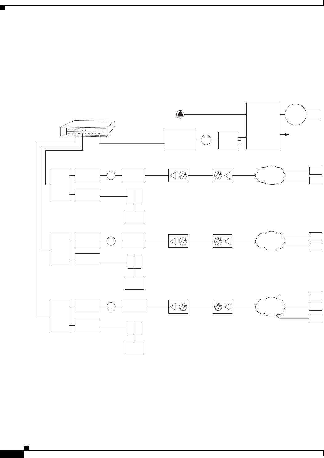
4-2
Cisco uBR7225VXR Universal Broadband Router Hardware Installation Guide
OL-17309-02
Chapter 4 Connecting the Cisco uBR7225VXR Router to the Cable Headend
Two-Way Data Headend Architecture
Two-Way Data Headend Architecture
Figure 4-1 shows a typical headend configuration configured for two-way data, including digitized voice
and fax.
Figure 4-1 Typical Cable Headend Configuration for Two-Way Data
Cisco
uBR7225VXR
Downstream
271671
Upstream
0 dBmV
6 dB
attenuator
40 dB
attenuator
3 dB
attenuator
Optical
receiver Fiber-optic
cable Distribution
network
+17 dBmV +13 dBmV
Cable
modems
+48 dBmV
+31 dBmV
2-way
splitter
+10 dBmV
6 dB
attenuator
40 dB
attenuator
8 dB
attenuator
+18 dBmV
+42 dBmV
+58 dBmV
2-way
splitter
+10 dBmV
6 dB
attenuator
40 dB
attenuator
21 dB
attenuator
+31 dBmV +42 dBmV
+49 dBmV
+50 dBmV
2-way
splitter
+10 dBmV
Laser
transmitter
Broadcast
Narrowcast
0 to 20 dB
attenuator
(as required)
8-way
tap
3-way
splitter
+17 dBmV
video carrier
(typical)
+7 dBmV
data carrier
(typical)
Optical
splitter
Node 1
Node 2
Downstream
forward
test point
Main
headend feed
X
X
X
Reverse optical
transmitter
Modem
transmit
levels
Modem
transmit
levels
Modem
transmit
levels
Reverse optical
transmitter
Reverse optical
transmitter
Optical
receiver Fiber-optic
cable Distribution
network
+17 dBmV
Optical
receiver Fiber-optic
cable Distribution
network
+17 dBmV
Downstream
(0 to +5 dBmV)
Cable
modem
LH
C
Diplex filter
Downstream
(0 to +5 dBmV)
Cable
modem
LH
C
Diplex filter
Downstream
(0 to +5 dBmV)
Cable
modem
LH
C
Diplex filter
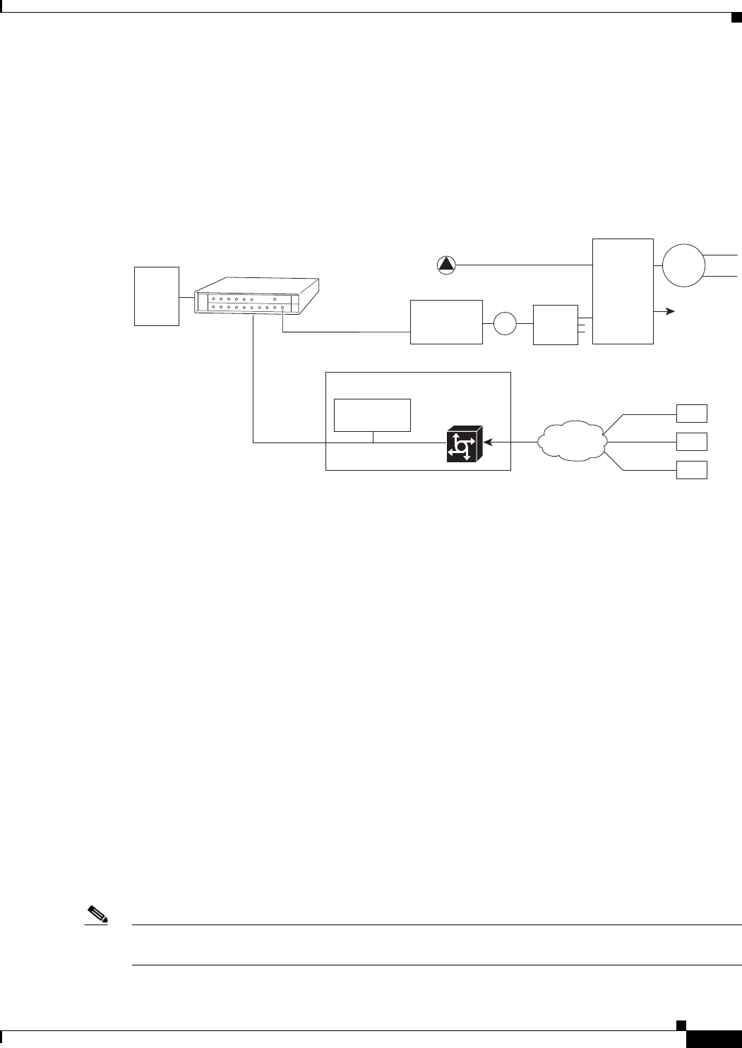
4-3
Cisco uBR7225VXR Universal Broadband Router Hardware Installation Guide
OL-17309-02
Chapter 4 Connecting the Cisco uBR7225VXR Router to the Cable Headend
One-Way Data Headend Architecture
One-Way Data Headend Architecture
Figure 4-2 shows a typical headend configuration configured for one-way (downstream) data in a telco
return cable system.
Figure 4-2 Typical Cable Headend Configuration for One-Way (Telco Return) Data
RF and Digital Data Overview
This section describes the interaction of digital and analog RF data as both signals are carried on the
hybrid fiber-coaxial (HFC) network.
Two-way digital data signals are more susceptible than one-way signals to stresses in the condition of
the HFC network. Degradation in video signal quality might not be noticed, but when two-way digital
signals share the network with video signals, digital signals might be hampered by the following types
of network impairments:
•Impulse and electrical noise—Impulse and electrical noise, usually forms of ingress, can enter the
network from sources within a home, such as hair dryers, light switches, and thermostats; or from
high-voltage lines that run near CATV cabling in the network. Areas of signal ingress may be located
and repaired by implementing a comprehensive signal leakage maintenance program.
•Amplifier thermal noise—Amplifiers add noise to the HFC network that usually goes unnoticed in
video signals, assuming a properly designed and operated network. Improperly configured
amplifiers will degrade digital data signals. The larger the network, the higher the probability of
amplifier thermal noise affecting the signals.
•Ingress noise—Ingress noise includes electrical sources (see “Impulse and electrical noise” above);
amateur radio transmissions; citizens band radios; or high-power shortwave broadcast signals,
which can interfere with frequencies anywhere between 3 and 65 MHz. These often are picked up
by cabling and equipment in the network.
Note Some HFC upstream equipment passes interfering signals below 5 MHz, which may overload the reverse
path.
DHCP
TFTP
TOD
servers
Cisco
uBR7225VXR
Downstream
RADIUS dial
security server
IP network access
Cisco network
access server
Telco return
cable modems
Upstream
Laser
transmitter
Broadcast
Narrowcast
0 to 20 dB
attenuator
(as required)
8-way
tap
3-way
splitter
+17 dBmV
video carrier
(typical)
+7 dBmV
data carrier
(typical)
Optical
splitter
Node 1
Node 2
Downstream
forward
test point
Main
headend feed
PSTN
271672

4-4
Cisco uBR7225VXR Universal Broadband Router Hardware Installation Guide
OL-17309-02
Chapter 4 Connecting the Cisco uBR7225VXR Router to the Cable Headend
Connecting and Configuring the Downstream
•Noise funneling—The upstream data path to the headend is susceptible to picking up noise and
interference from anywhere in the network, and all upstream noise ultimately ends up at the
headend. This effect is known as noise funneling because of the cumulative nature of the noise from
one or more locations in the network that becomes concentrated at the headend. As a network
serviced by a single upstream receiver increases in size, the probability of noise funneling also
increases.
•Variable transmit levels—Signal loss over coaxial cable is affected by temperature. This can cause
variations of 6 to 10 dB per year.
•Clipping—The lasers in fiber-optic transmitters can stop transmitting light (clipping) when input
levels are excessive. Excessive input levels may cause bit errors and reduced data throughput in both
the upstream and downstream transmissions. If a laser is overdriven as briefly as a fraction of a
second, clipping can occur.
Connecting and Configuring the Downstream
After you install the Cisco uBR7225VXR universal broadband router in your headend site, you must
connect the Cisco uBR7225VXR router to the HFC network and configure the network. The following
sections describe how to connect to and configure the downstream.
Installing and Configuring the Upconverter
The Cisco uBR-MC16U/E-16U and Cisco uBR-MC28U/E-28U cable interface line cards have an
onboard integrated upconverter that generates an RF signal suitable for connection to a combiner and
transmission on the coaxial cable network, without the need for any external upconverters.
Note For more information, refer to the Cisco uBR7200 Series Cable Interface Line Card Hardware
Installation Guide at the following URL:
http://www.cisco.com/en/US/docs/interfaces_modules/cable/line_cards/installation/guide/mcxxfru.htm
l
Measuring the Downstream RF Signal
The configuration of the downstream digitally modulated carrier at the headend is critical to the
performance of the Cisco uBR7225VXR universal broadband router and cable modems. The following
guidelines are provided to assist you in configuring the RF signal to the necessary specifications. There
are two options you can use to measure the RF signal with a spectrum analyzer. These options are
described in the following sections:
•Measuring the Downstream RF Signal Using the Channel Power Option on a Spectrum Analyzer,
page 4-5
•Measuring the Downstream RF Signal Using CATV Mode on a Spectrum Analyzer, page 4-11
(equipped with digital channel power mode)

4-5
Cisco uBR7225VXR Universal Broadband Router Hardware Installation Guide
OL-17309-02
Chapter 4 Connecting the Cisco uBR7225VXR Router to the Cable Headend
Measuring the Downstream RF Signal
These two sections describe the procedures necessary to use a spectrum analyzer. You may also use a
signal level meter that has the ability to measure the average power level of digitally modulated carriers,
as well as a QAM analyzer. Some instruments to perform these measurements include:
•Acterna SDA-5000 w/Option 4 (http://www.acterna.com)
•Agilent 8591C, N1776A, 2010 or 3010 (http://www.tm.agilent.com)
•Sunrise Telecom AT-2000RQ, CM1000 or CR1200R (http://www.sunrisetelecom.com)
•Telsey DMA-120, DMA-121 or DMA122 (http://www.telsey.it)
•Trilithic 860DSP w/Option QA1 (http://www.trilithic.com)
If you complete these measurements using one of the previously mentioned options, your downstream
signal can be verified as correctly configured and it can assist you with troubleshooting your network
later on.
If you want to measure the downstream RF signal using the spectrum analyzer channel power option,
proceed to the following section, “Measuring the Downstream RF Signal Using the Channel Power
Option on a Spectrum Analyzer.” If you want to measure the downstream RF signal using CATV mode,
proceed to the “Measuring the Downstream RF Signal Using CATV Mode on a Spectrum Analyzer”
section on page 4-11.
Measuring the Downstream RF Signal Using the Channel Power Option on a
Spectrum Analyzer
The following sections describe how to measure the downstream RF signal using the channel power
option on a spectrum analyzer:
•Measuring the Downstream IF Signal at the Cisco uBR7225VXR Router, page 4-5
•Measuring the Downstream RF Signal at the Upconverter Output, page 4-7
Measuring the Downstream IF Signal at the Cisco uBR7225VXR Router
Note Refer to the user guide that accompanied your spectrum analyzer to determine the exact steps required
to use your analyzer to perform these measurements.
Step 1 Connect a spectrum analyzer to the downstream connector on a Cisco cable interface line card installed
in a Cisco uBR7225VXR router.
Step 2 Turn the power switch on the spectrum analyzer to the ON position.
Step 3 Set the spectrum analyzer to view the downstream intermediate frequency (IF) signal with a center
frequency of 44 MHz for a North American headend or 36.125 MHz for a European headend.
Step 4 Set the span to 10 MHz. Your analyzer should display a signal similar to the one shown in Figure 4-3.
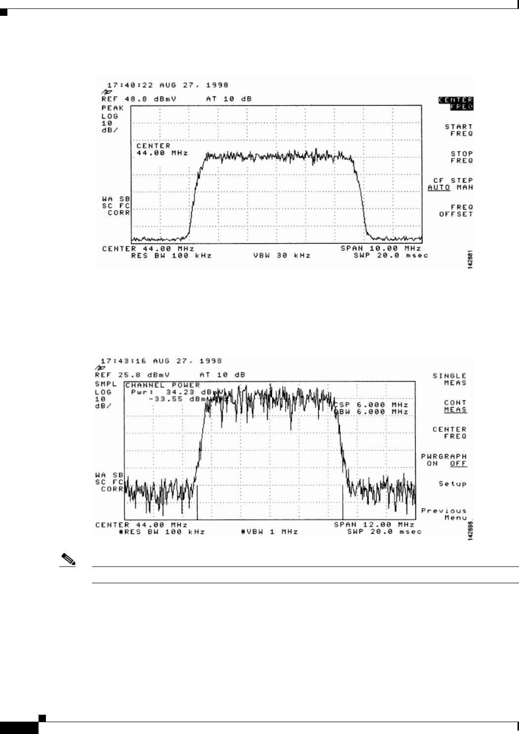
4-6
Cisco uBR7225VXR Universal Broadband Router Hardware Installation Guide
OL-17309-02
Chapter 4 Connecting the Cisco uBR7225VXR Router to the Cable Headend
Measuring the Downstream RF Signal
Figure 4-3 Viewing the Downstream IF Signal on a Spectrum Analyzer
Step 5 Measure the IF signal using the channel power option on your spectrum analyzer. Set your channel
spacing and your channel bandwidth to 6 MHz. Your analyzer should display a signal similar to the one
shown in Figure 4-4.
Figure 4-4 Measuring the IF Channel Power
Note The IF channel power in Figure 4-4 is +34.23 dBmV, as displayed on the spectrum analyzer.
Step 6 Select the video averaging feature. Your spectrum analyzer should display a signal similar to the one
shown in Figure 4-5.
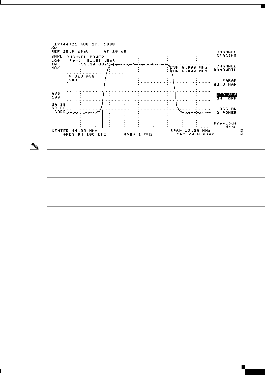
4-7
Cisco uBR7225VXR Universal Broadband Router Hardware Installation Guide
OL-17309-02
Chapter 4 Connecting the Cisco uBR7225VXR Router to the Cable Headend
Measuring the Downstream RF Signal
Figure 4-5 Measuring the IF Channel Power Using Video Averaging
Note The approximate in-channel peak-to-valley flatness may be verified using the spectrum analyzer’s video
averaging feature. Be aware, however, that amplitude values registered while in the video averaging
mode are typically around 2.5 dB below the actual channel power.
Measuring the Downstream RF Signal at the Upconverter Output
Step 1 Disconnect the spectrum analyzer from the cable interface line card downstream connector.
Step 2 Connect the downstream output of the cable interface line card to the upconvertor input connector.
Step 3 Connect the spectrum analyzer to the RF output of the upconverter. If your spectrum analyzer input is
overloaded, you might see artifacts that are internally generated by the spectrum analyzer. The artifacts
are circled on the analyzer trace shown in Figure 4-6. Add attenuation as necessary to correct the
overload condition.
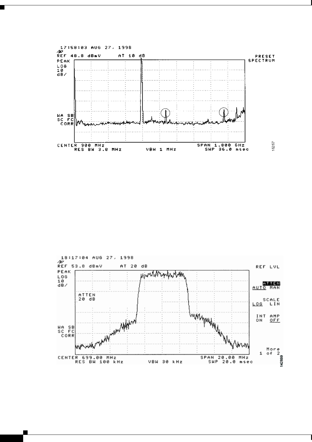
4-8
Cisco uBR7225VXR Universal Broadband Router Hardware Installation Guide
OL-17309-02
Chapter 4 Connecting the Cisco uBR7225VXR Router to the Cable Headend
Measuring the Downstream RF Signal
Figure 4-6 Overloaded Spectrum Analyzer Input
Step 4 Set the input of the upconverter to a digital QAM signal and the output level to the manufacturer’s
recommended settings. Typical output amplitudes range from +50 to +58 dBmV, although DOCSIS
specifies +61 dBmV.
Step 5 Set the spectrum analyzer to view the RF signal at the center frequency you selected for your headend.
In this example, the RF center frequency is 699 MHz. Set your span to 20 MHz. Finally, set your channel
spacing and your channel bandwidth to 6 MHz.
If the RF signal is causing an overload condition on the spectrum analyzer input, your analyzer might
display a signal similar to the one shown in Figure 4-7. The sloping of the lines at the sides of the signal
indicates a false reading.
Figure 4-7 Measuring the RF Signal at the Upconverter Output—Overload Condition
Step 6 If you add attenuation to the input to the spectrum analyzer you can correct the overload condition as
shown in Figure 4-8.
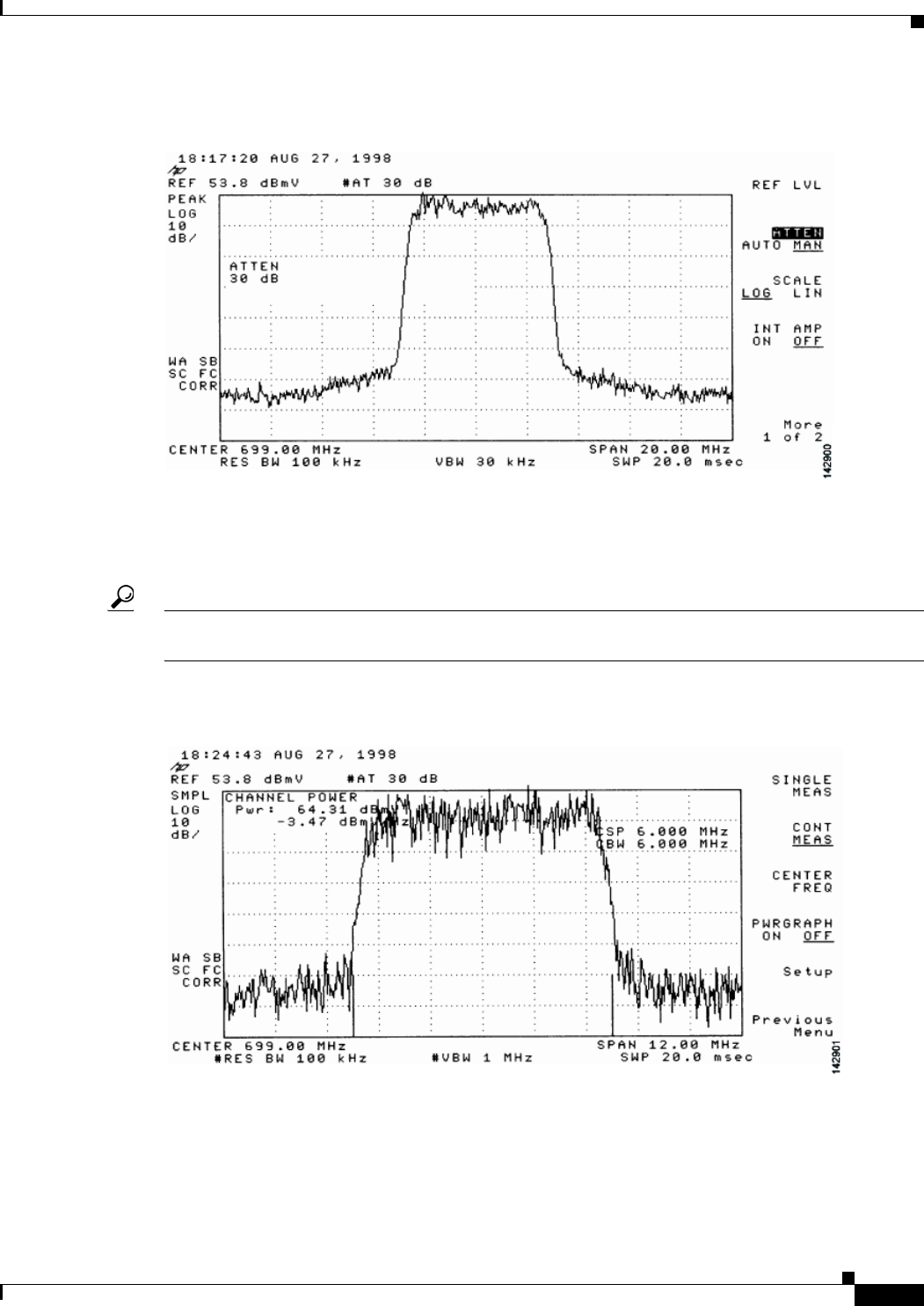
4-9
Cisco uBR7225VXR Universal Broadband Router Hardware Installation Guide
OL-17309-02
Chapter 4 Connecting the Cisco uBR7225VXR Router to the Cable Headend
Measuring the Downstream RF Signal
Figure 4-8 Measuring the RF Signal at the Upconverter Output—Overload Condition Corrected
with Attenuation
Step 7 Change the spectrum analyzer settings to view the digital channel power. This setting enables you to see
if there is too much power on the upconverter output. In Figure 4-9, the upconverter output is reading
+64.31 dBmV, which is beyond the DOCSIS-specified range of +50 to +61 dBmV.
Tip A spectrum analyzer might become overloaded and produce false readings (such as internally generated
spurs) when measuring a signal at this amplitude.
Figure 4-9 Measuring the RF Signal at the Upconverter Output—Upconverter Output Level Too
High
Step 8 Adjust the power on the upconverter output to ensure that it is between +50 and +61 dBmV. In
Figure 4-10, the upconverter output is reading +57.06 dBmV, which is within the correct range.
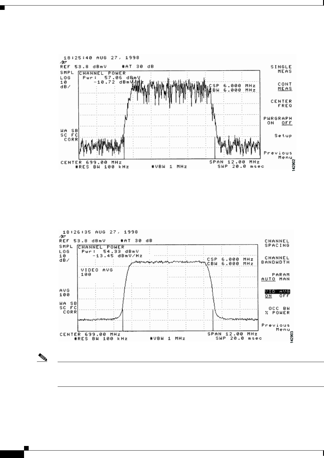
4-10
Cisco uBR7225VXR Universal Broadband Router Hardware Installation Guide
OL-17309-02
Chapter 4 Connecting the Cisco uBR7225VXR Router to the Cable Headend
Measuring the Downstream RF Signal
Figure 4-10 Measuring the RF Signal at the Upconverter Output—Output Adjusted to Correct
Range
Step 9 Select the video averaging feature on the spectrum analyzer. The signal becomes smoother and
frequency response problems might become visible. Your analyzer now displays an RF signal similar to
the one shown in Figure 4-11.
Figure 4-11 Measuring the RF Signal at the Upconverter Output Using Video Averaging
Note The approximate in-channel peak-to-valley flatness may be verified using the spectrum analyzer’s video
averaging feature. Be aware, however, that amplitude values registered while in the video averaging
mode are typically around 2.5 dB below the actual channel power.

4-11
Cisco uBR7225VXR Universal Broadband Router Hardware Installation Guide
OL-17309-02
Chapter 4 Connecting the Cisco uBR7225VXR Router to the Cable Headend
Measuring the Downstream RF Signal
Step 10 Verify that your headend RF measurements meet the recommended DOCSIS parameters listed in the
tables in Appendix B, “RF Specifications.” Record your headend settings and measurements in your
headend site log (Appendix G, “Site Log”). This will assist in troubleshooting the
Cisco uBR7225VXR router installation later in the process.
This completes the procedure to measure the downstream RF signal using the channel power option.
Proceed to the “Measuring the RF Signal at the Forward Test Point on a Laser Transmitter” section on
page 4-37.
Measuring the Downstream RF Signal Using CATV Mode on a
Spectrum Analyzer
The following two sections describe the methods you may use to measure the downstream RF signal
using CATV mode (digital channel power option) on a spectrum analyzer:
•Measuring the Downstream IF Signal at the Cisco uBR7225VXR Router Using CATV Mode,
page 4-11
•Measuring the Downstream RF Signal at the Upconverter Output Using CATV Mode, page 4-14
Note We recommend using as recent a model of spectrum analyzer as possible to perform the two analyses
described here. You can use spectrum analyzers, such as the Agilent 8591C (http://www.tm.agilent.com)
or the Tektronix 2715 (http://www.tek.com) to help you perform the tasks outlined in this section.
Measuring the Downstream IF Signal at the Cisco uBR7225VXR Router Using CATV Mode
Note Refer to the user guide that accompanied your spectrum analyzer to determine the exact steps required
to use your analyzer to perform these measurements.
Step 1 Connect a spectrum analyzer to the downstream connector on a Cisco cable interface card installed in a
Cisco uBR7225VXR router.
Step 2 Turn the power switch on the spectrum analyzer to the on position.
Step 3 Set the spectrum analyzer to CATV mode (CATV analyzer option) and select the channel measurement
option to view the downstream intermediate frequency (IF) signal. Your analyzer should display a signal
similar to the one shown in Figure 4-12.
Note Figure 4-12 shows the first of three screens that will be displayed by an Agilent 8591C when you use the
analyzer in this mode. Figure 4-13 is the last of the three screens displayed.
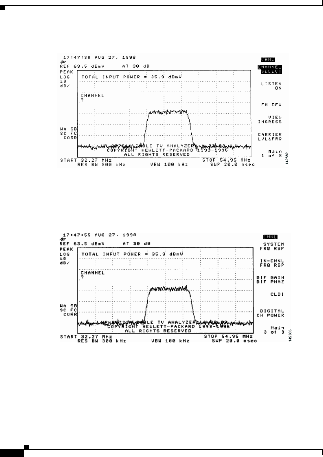
4-12
Cisco uBR7225VXR Universal Broadband Router Hardware Installation Guide
OL-17309-02
Chapter 4 Connecting the Cisco uBR7225VXR Router to the Cable Headend
Measuring the Downstream RF Signal
Figure 4-12 Viewing the Downstream IF Signal on a Spectrum Analyzer in CATV Mode—Initial
Screen
Step 4 Advance to the last of the three screens in this display. Your analyzer should display a signal similar to
the one shown in Figure 4-13.
Figure 4-13 Viewing the IF Signal on a Spectrum Analyzer in CATV Mode—Preliminary Digital
Channel Power Screen
Step 5 Enter a digital channel to measure and select digital channel power. Your spectrum analyzer will display
a signal similar to the one shown in Figure 4-14.
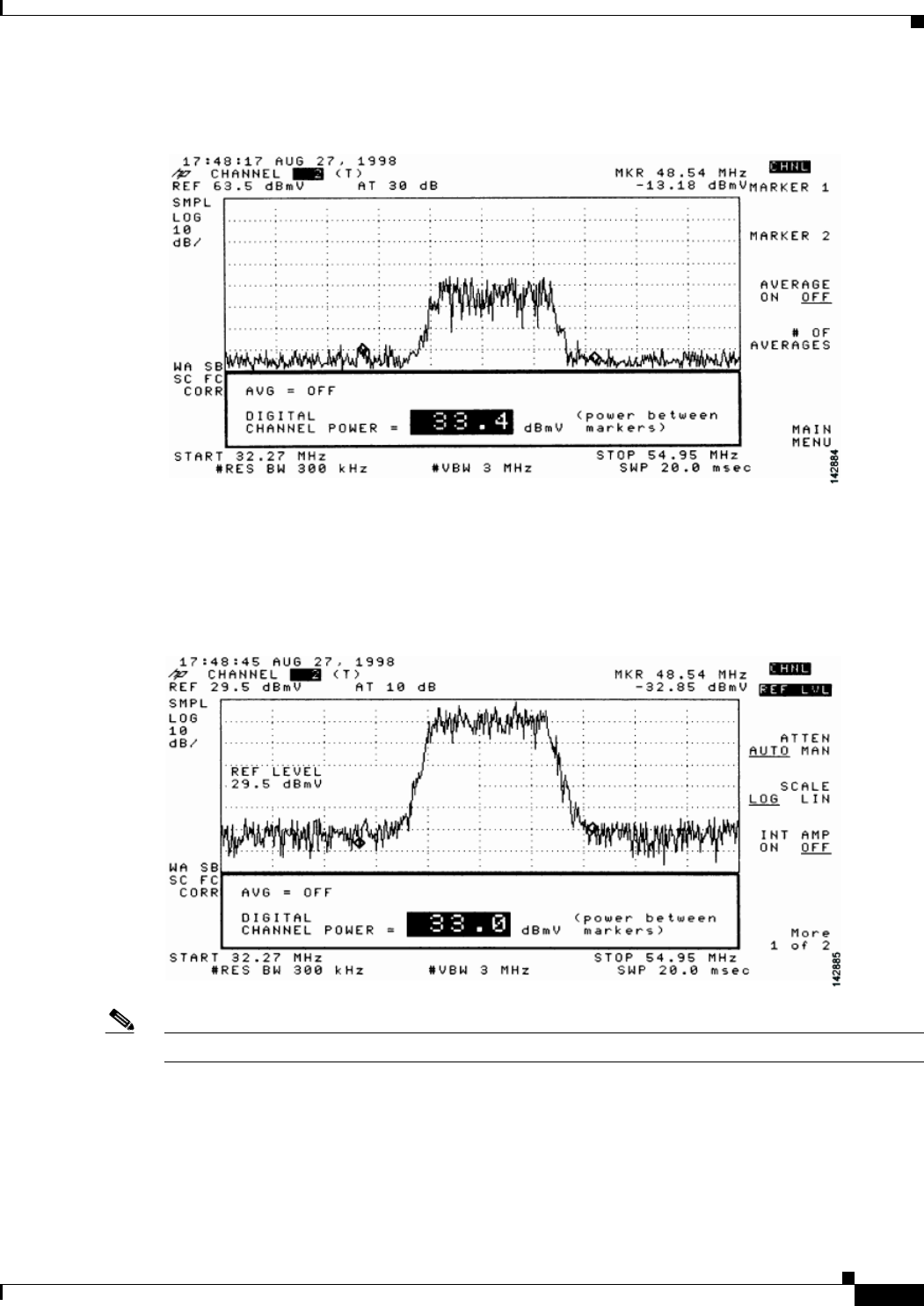
4-13
Cisco uBR7225VXR Universal Broadband Router Hardware Installation Guide
OL-17309-02
Chapter 4 Connecting the Cisco uBR7225VXR Router to the Cable Headend
Measuring the Downstream RF Signal
Figure 4-14 Measuring the IF Signal on a Spectrum Analyzer in CATV Mode—Digital Channel
Power Screen
Step 6 Using the spectrum analyzer’s reference level control, adjust the amplitude of the displayed signal until
the shape of the signal is clearly distinguishable as a digitally modulated carrier, as shown in
Figure 4-15.
Figure 4-15 Measuring the IF Signal on a Spectrum Analyzer in CATV Mode—Adjusted Digital
Channel Power Screen
Note The IF channel power in Figure 4-15 is +33 dBmV, as displayed on the spectrum analyzer.
Step 7 Select the video averaging feature. Your spectrum analyzer should display a signal similar to the one
shown in Figure 4-16.
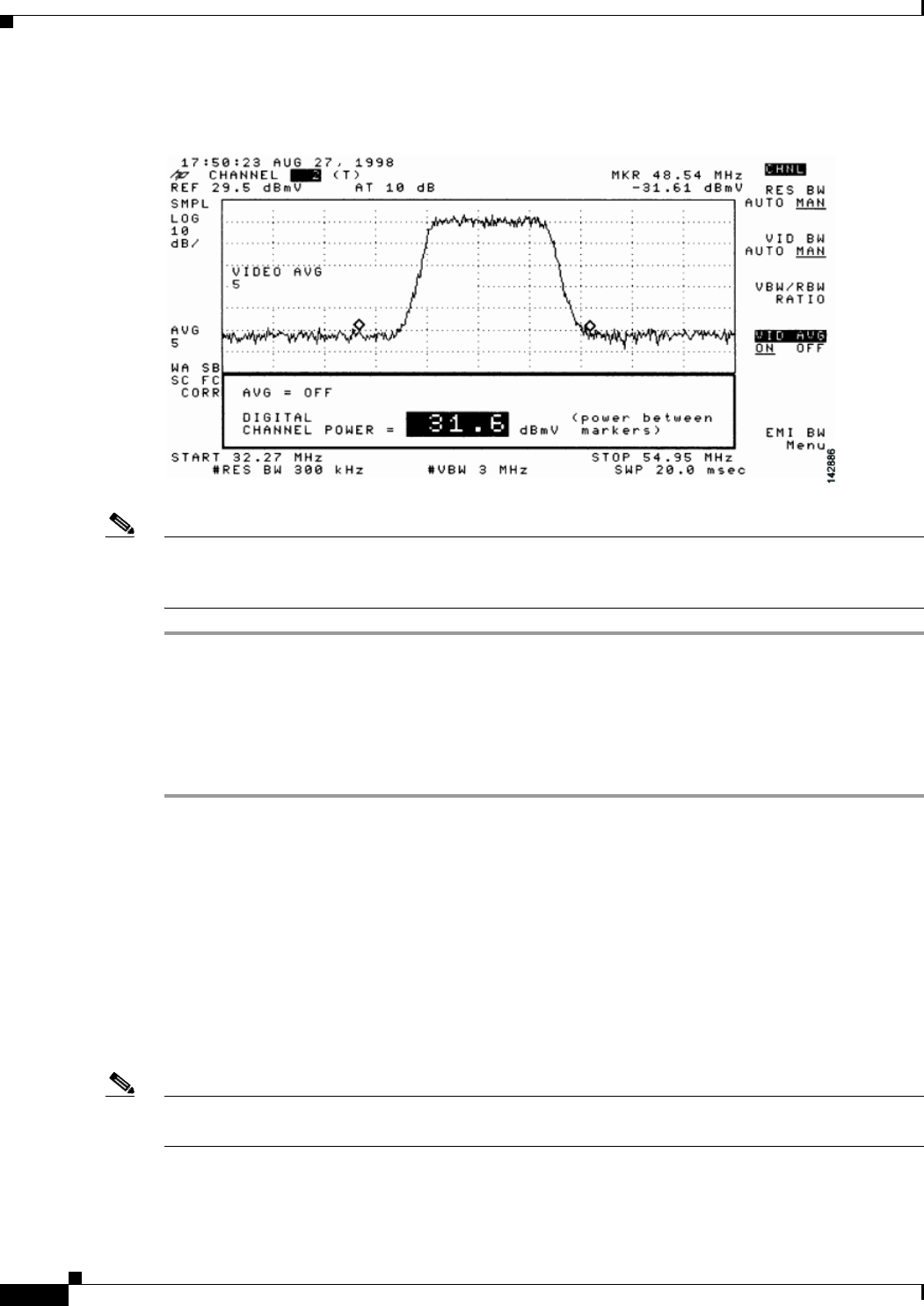
4-14
Cisco uBR7225VXR Universal Broadband Router Hardware Installation Guide
OL-17309-02
Chapter 4 Connecting the Cisco uBR7225VXR Router to the Cable Headend
Measuring the Downstream RF Signal
Figure 4-16 Measuring the IF Signal on a Spectrum Analyzer in CATV Mode—Digital Channel
Power Screen (Using Video Averaging)
Note The approximate in-channel peak-to-valley flatness can be verified using the spectrum analyzer’s video
averaging feature. Be aware, however, that amplitude values registered while in the video averaging
mode are typically around 2.5 dB below the actual channel power.
Proceed to the next section, “Measuring the Downstream RF Signal at the Upconverter Output Using
CATV Mode.”
Measuring the Downstream RF Signal at the Upconverter Output Using CATV Mode
Step 1 Disconnect the spectrum analyzer from the cable interface card downstream connector.
Step 2 Connect the downstream output of the cable interface card to the upconverter input connector.
Step 3 Connect the spectrum analyzer to the RF output of the upconverter.
Step 4 Set the upconverter output level to the manufacturer’s recommended settings. Typical output amplitudes
range from +50 to +58 dBmV, although DOCSIS specifies levels as high as +61 dBmV.
Step 5 Set the spectrum analyzer to view the RF signal at the center frequency you selected for your headend.
In this example, the RF center frequency is 705 MHz.
Step 6 Set the spectrum analyzer to CATV mode (CATV analyzer option) and select the channel measurement
option to view the downstream RF signal. Your spectrum analyzer should display a signal similar to the
one shown in Figure 4-12.
Note Figure 4-17 shows the first of three screens that will be displayed by an Agilent 8591C when you use the
analyzer in this mode. Figure 4-18 is the last of the three screens displayed.
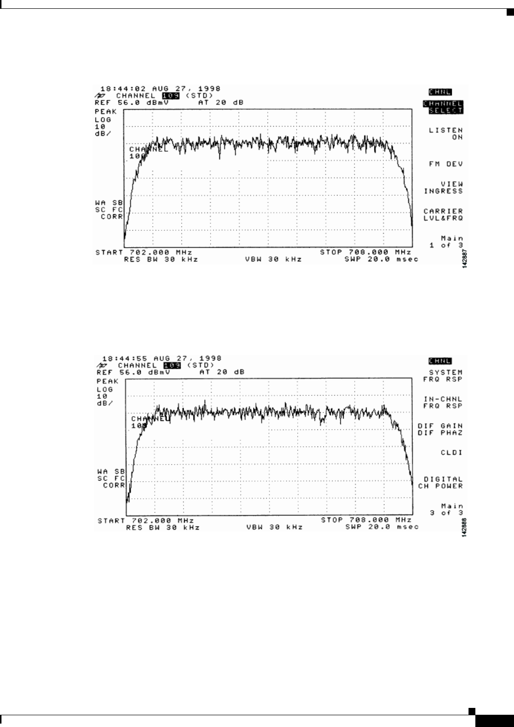
4-15
Cisco uBR7225VXR Universal Broadband Router Hardware Installation Guide
OL-17309-02
Chapter 4 Connecting the Cisco uBR7225VXR Router to the Cable Headend
Measuring the Downstream RF Signal
Figure 4-17 Viewing the Downstream RF Signal on a Spectrum Analyzer in CATV Mode—Initial
Screen
Step 7 Advance to the last of the three screens in this display. Your analyzer should display a signal similar to
the one shown in Figure 4-18.
Figure 4-18 Viewing the RF Signal on a Spectrum Analyzer in CATV Mode—Preliminary Digital
Channel Power Screen
Step 8 Enter a digital channel to measure and select digital channel power. Your spectrum analyzer will display
a signal similar to the one shown in Figure 4-19.
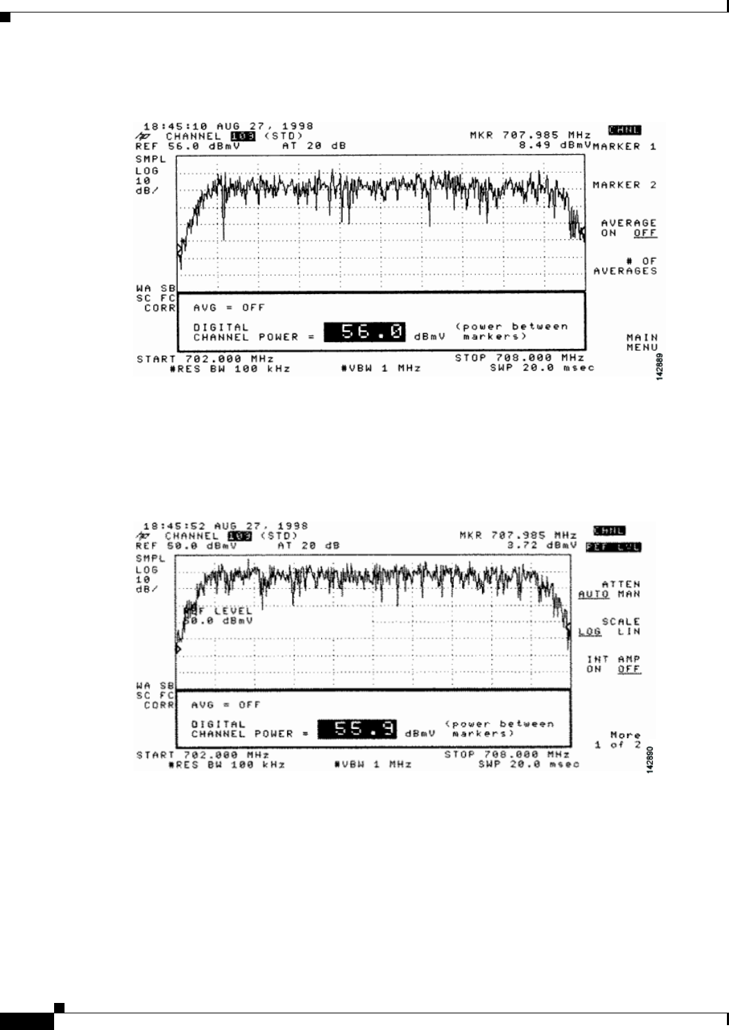
4-16
Cisco uBR7225VXR Universal Broadband Router Hardware Installation Guide
OL-17309-02
Chapter 4 Connecting the Cisco uBR7225VXR Router to the Cable Headend
Measuring the Downstream RF Signal
Figure 4-19 Measuring the RF Signal at the Upconverter Output in CATV Mode—Digital Channel
Power Screen
Step 9 Using the spectrum analyzer’s reference level control, adjust the amplitude of the displayed signal until
the signal peak is within the top graticule of the analyzer’s display grid, as shown in Figure 4-20.
Figure 4-20 Measuring the RF Signal at the Upconverter Output in CATV Mode—Adjusted Digital
Channel Power Screen
Step 10 Select the video averaging feature. Your spectrum analyzer should display a signal similar to the one
shown in Figure 4-21.
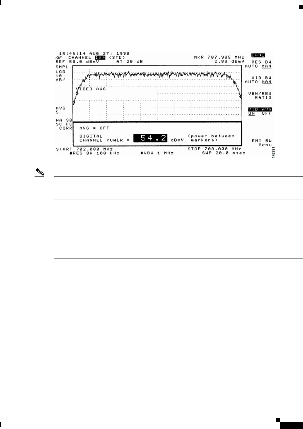
4-17
Cisco uBR7225VXR Universal Broadband Router Hardware Installation Guide
OL-17309-02
Chapter 4 Connecting the Cisco uBR7225VXR Router to the Cable Headend
Measuring the Downstream RF Signal
Figure 4-21 Measuring the RF Signal at the Upconverter Output in CATV Mode—Digital Channel
Power Screen Using Video Averaging
Note The approximate in-channel peak-to-valley flatness can be verified using the spectrum analyzer’s video
averaging feature. Be aware, however, that amplitude values registered while in the video averaging
mode are typically around 2.5 dB below the actual channel power.
Step 11 Verify that your headend RF measurements meet the recommended DOCSIS parameters listed in the
tables in Appendix B, “RF Specifications.”
Step 12 Record your headend settings and measurements in Appendix G, “Site Log.” as you verify them. This
will assist in troubleshooting the Cisco uBR7225VXR router installation later in the process.
Step 13 After you have analyzed and adjusted the RF signal according to the steps outlined on the preceding
pages, proceed to the “Connecting and Configuring the Upstream” section on page 4-18.

4-18
Cisco uBR7225VXR Universal Broadband Router Hardware Installation Guide
OL-17309-02
Chapter 4 Connecting the Cisco uBR7225VXR Router to the Cable Headend
Connecting and Configuring the Upstream
Connecting and Configuring the Upstream
The following sections describe how to connect and configure the upstream for digital data.
Connecting the Upstream to the Optical Receiver
To connect the upstream to the optical receiver, use a 2-way splitter as a combiner to leave the DOCSIS
cable modem connected at the headend, and connect the upstream headend cable to the optical receiver.
(See Figure 4-22.)
The default upstream input level to the Cisco uBR7225VXR cable interface line card is 0 dBmV. You
may adjust the upstream input level to other values using the Cisco IOS software running on your router.
The Cisco uBR7225VXR router uses automatic power control when transmitting to remote
cable modems. Accurately setting the power level helps to ensure reliable cable modem operation.
Table 4-1 provides upstream input power ranges for the various cable interface line cards available for
the Cisco uBR7225VXR router, depending on the channel bandwidth you are using.
Note If you have a Cisco uBRMC16x cable interface line card (six upstream ports and one downstream port)
installed in your Cisco uBR7225VXR router, the 2-way splitter described above would be replaced by
six 2-way splitters (one splitter per upstream port). This would enable you to connect to all of the
available upstream ports on the Cisco uBRMC16x.
Table 4-1 Upstream Input Power Ranges According to Cable Interface Line Card Type
Channel Bandwidth Cisco MC11 FPGA Cisco MC16E and MC16S DOCSIS Specification
200 KHz N/A –10 to +25 dBmV –16 to +14 dBmV
400 KHz N/A –10 to +25 dBmV –13 to +17 dBmV
800 KHz N/A –10 to +25 dBmV –10 to +20 dBmV
1.6 MHz –10 to +10 dBmV –10 to +25 dBmV –7 to +23 dBmV
3.2 MHz N/A –10 to +25 dBmV –4 to +26 dBmV
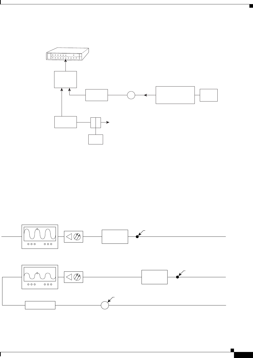
4-19
Cisco uBR7225VXR Universal Broadband Router Hardware Installation Guide
OL-17309-02
Chapter 4 Connecting the Cisco uBR7225VXR Router to the Cable Headend
Connecting and Configuring the Upstream
Figure 4-22 Connecting and Configuring the Upstream
Testing the Upstream Configuration
To test the upstream configuration, insert a test signal of known amplitude (+17 dBmV is shown in this
example) into the fiber node and measure the amplitude output level at the output of the headend’s
optical receiver. This measurement depends on return laser performance and optical distance. This
procedure is known as establishing the “X-level” test point. (See Figure 4-23.)
Figure 4-23 The “X-level” Test Point
Cisco
uBR7225VXR
271676
Upstream
Optical
receiver
To downstream forward
test point on laser transmitter
40 dB
attenuator
2-way
splitter
(combiner)
10 dB
attenuator
Optional attenuator
to adjust X-level point
measurement
X-level test point signal level
must be the same for all
optical receivers (+/- 0.5 dB),
See Fig. 4-36 and Fig 4-37
X
Cable
modem
LH
C
Diplex filter
14045
Spectrum analyzer Optical
receiver
Fiber node
0.5 milliwatt
Fiber node
1.0 milliwatt
Spectrum analyzer Optical
receiver
1dB attenuator
+11 dBmV
X-level test point = +10 dBmV
(in this example)
30 km
10 km
+17 dBmV Insert +17 dBmV signal
X
Measure +10 dBmV at this point
Insert +17 dBmV signal
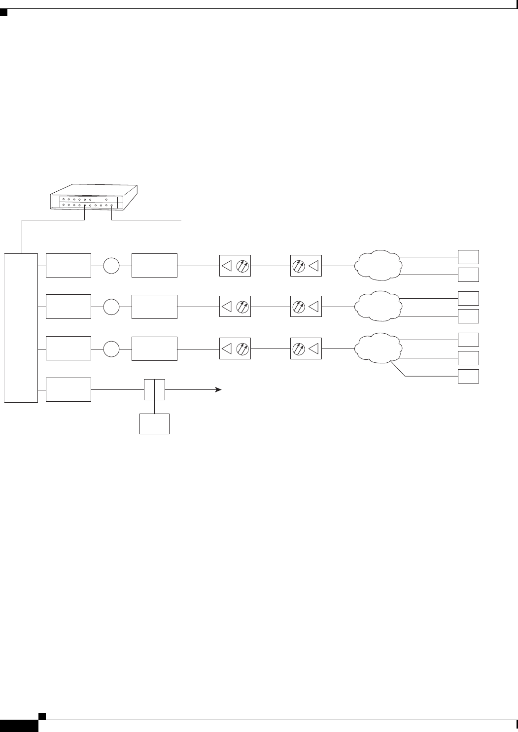
4-20
Cisco uBR7225VXR Universal Broadband Router Hardware Installation Guide
OL-17309-02
Chapter 4 Connecting the Cisco uBR7225VXR Router to the Cable Headend
Connecting and Configuring the Upstream
This “X-level” test point measurement will be different for every fiber node in the HFC network until
you adjust the attenuation on the upstream. You must adjust the attenuation so that this measurement is
the same on every fiber node. If you change a receiver or a transmitter at the fiber node, or if you unplug
a connector and plug it back in, you must recheck this amplitude measurement. Figure 4-24 shows how
three distribution network “X-level” test points connected to the same upstream port are all calibrated to
+10 dBmV using different attenuators.
Figure 4-24 Calibrating Multiple “X-level” Test Points Connected to One Upstream Port
Figure 4-25 shows how three distribution network “X-level” test points connected to the three different
upstream ports are all calibrated to +10 dBmV using different attenuators.
Cisco
uBR7225VXR
Downstream
271677
Upstream
0 dBmV
3 dB
attenuator
3 dB
attenuator
3 dB
attenuator
40 dB
attenuator
3 dB
attenuator
8 dB
attenuator
21 dB
attenuator
Cable
modems
+48 dBmV
+31 dBmV
+42 dBmV
+50 dBmV
+46 dBmV
+49 dBmV
+58 dBmV
4-way
splitter
X
X
X
+10 dBmV
+10 dBmV
+10 dBmV
To downstream
forward test point
on laser transmitter
+13 dBmV
+18 dBmV
+31 dBmV
Reverse optical
transmitter
Optical
receiver Fiber-optic
cable Distribution
network
+17 dBmV
Reverse optical
transmitter
Optical
receiver Fiber-optic
cable Distribution
network
+17 dBmV
Reverse optical
transmitter
Optical
receiver Fiber-optic
cable Distribution
network
+17 dBmV
Modem transmit levels
Modem transmit levels
Modem transmit levels
Cable
modem
LH
C
Diplex filter
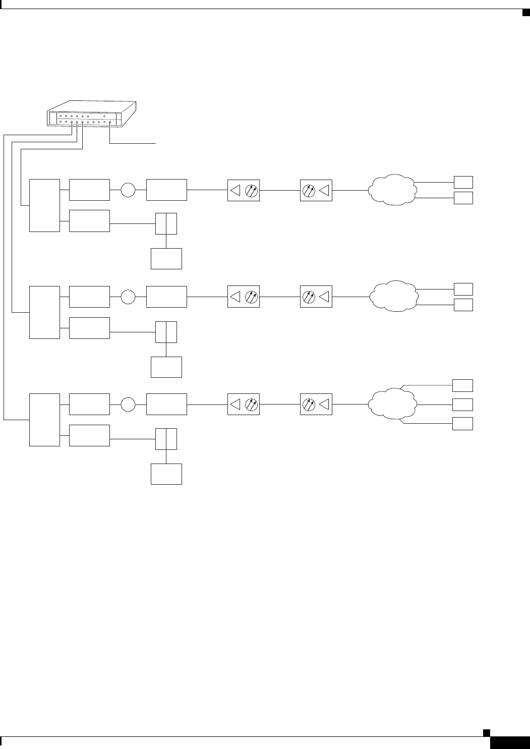
4-21
Cisco uBR7225VXR Universal Broadband Router Hardware Installation Guide
OL-17309-02
Chapter 4 Connecting the Cisco uBR7225VXR Router to the Cable Headend
Connecting and Configuring the Upstream
Figure 4-25 Calibrating Multiple “X-level” Test Points Connected to Multiple Upstream Ports
Cisco
uBR7225VXR
Downstream
271678
Upstream
0 dBmV
Downstream
(0 to +5 dBmV)
Cable
modem
LH
C
6 dB
attenuator
40 dB
attenuator
3 dB
attenuator
+13 dBmV
Cable
modems
+48 dBmV
+31 dBmV
2-way
splitter
+10 dBmV
Diplex filter
Downstream
(0 to +5 dBmV)
Cable
modem
LH
C
3 dB
attenuator
Diplex filter
Downstream
(0 to +5 dBmV)
Cable
modem
LH
C
Diplex filter
6 dB
attenuator
40 dB
attenuator
+18 dBmV
+42 dBmV
+58 dBmV
2-way
splitter
+10 dBmV
6 dB
attenuator
40 dB
attenuator
21 dB
attenuator
+31 dBmV +42 dBmV
+49 dBmV
+50 dBmV
2-way
splitter
+10 dBmV
X
X
X
Reverse optical
transmitter
Optical
receiver Fiber-optic
cable Distribution
network
+17 dBmV
Reverse optical
transmitter
Optical
receiver Fiber-optic
cable Distribution
network
+17 dBmV
Reverse optical
transmitter
Optical
receiver Fiber-optic
cable Distribution
network
+17 dBmV
Modem
transmit
levels
Modem
transmit
levels
Modem
transmit
levels

4-22
Cisco uBR7225VXR Universal Broadband Router Hardware Installation Guide
OL-17309-02
Chapter 4 Connecting the Cisco uBR7225VXR Router to the Cable Headend
Measuring the Upstream RF Signal
Measuring the Upstream RF Signal
You can use a spectrum analyzer to measure the upstream signal from one or more remote cable modems
in a two-way data cable network. Performing this procedure can help alert you to potential problems in
your cable network’s upstream configuration before a problem occurs. This helps to avoid trying to solve
a problem after a remote cable modem has experienced a failure in service. This procedure is referred to
as the “zero-span” method.
Measuring the Upstream RF Signal Using a Spectrum Analyzer
This procedure is designed to help you accurately measure an upstream RF signal where no adjacent
channels are in use. To measure an upstream RF signal with active adjacent channels, refer to the “Using
the Zero-Span Method with Adjacent Upstream Channels” section on page 4-28.
Note Refer to the user guide that accompanied your spectrum analyzer to determine the exact steps required
to use your analyzer to perform these measurements.
Step 1 Connect the spectrum analyzer to the upstream signal from your cable network.
Step 2 Turn the power switch on the spectrum analyzer to the on position.
Step 3 Set the spectrum analyzer to view the upstream RF signal with a center frequency matching the actual
upstream center frequency defined in your Cisco uBR7225VXR router configuration file.
Step 4 Set the spectrum analyzer’s span to 0 MHz.
Note You can view the configuration file for your Cisco uBR7225VXR router by using the
show controller cable slot/upstream/port command, available in Cisco IOS Release 11.3(6)NA or later
releases and Cisco IOS Release 12.0(5)T1 or later releases. For example, if you wanted to view the
center frequency of port 0 on a cable interface card in slot 3, you would enter the
show controller cable 3/0 command.
If you have assigned spectrum groups in your configuration file, use the show cable hop command to
display the current upstream center frequency for each cable interface.
Step 5 Set both the resolution bandwidth and the video bandwidth on the spectrum analyzer to 3 MHz and the
sweep rate to 20 microseconds. Provided there is a large amount of activity on your upstream channel,
the spectrum analyzer should display a signal similar to the one shown in Figure 4-26.

4-23
Cisco uBR7225VXR Universal Broadband Router Hardware Installation Guide
OL-17309-02
Chapter 4 Connecting the Cisco uBR7225VXR Router to the Cable Headend
Measuring the Upstream RF Signal
Figure 4-26 Measuring the Upstream RF Signal—Setting the Resolution and Video Channel
Bandwidth
Tip The horizontal line passing through the center of the spectrum analyzer display in Figure 4-26 is the
trigger line.
Step 6 Set the sweep value to 80 microseconds. Your spectrum analyzer should display a signal similar to the
one shown in Figure 4-27.
Note Be sure that your particular spectrum analyzer is capable of supporting sweep times as short as 80
microseconds.
Figure 4-27 Measuring the Upstream RF Signal—Setting the Sweep Time Period
Step 7 Position the trigger line on the spectrum analyzer so that it is roughly in the middle (approximately
halfway between the highest and lowest portions) of the upstream RF signal.
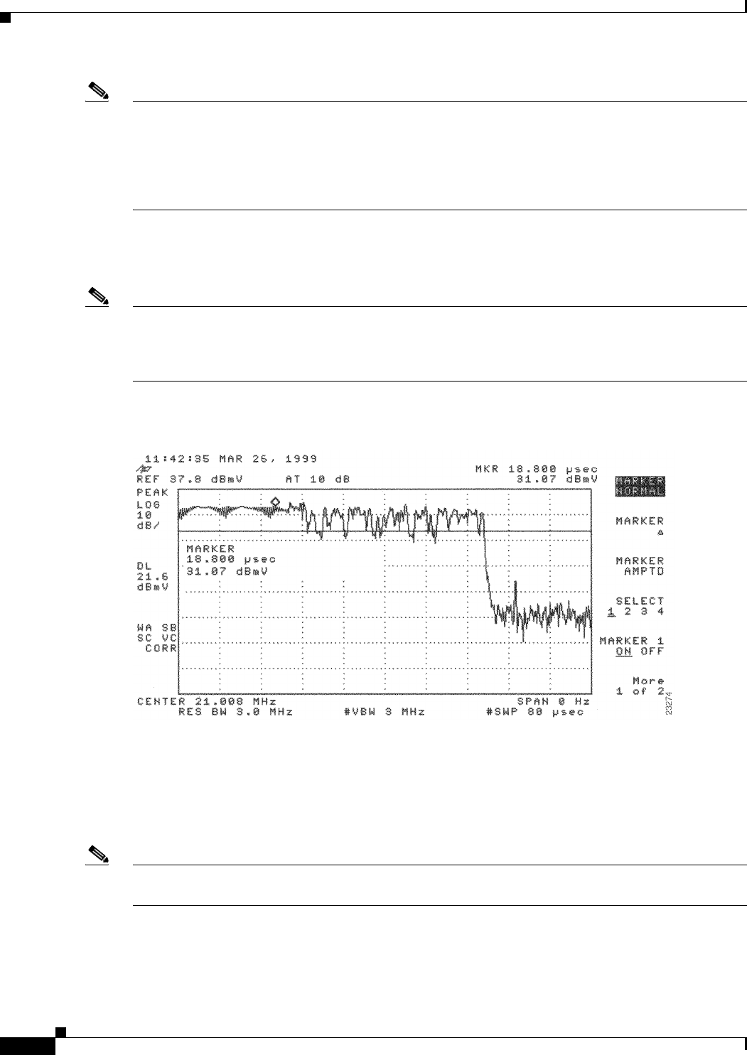
4-24
Cisco uBR7225VXR Universal Broadband Router Hardware Installation Guide
OL-17309-02
Chapter 4 Connecting the Cisco uBR7225VXR Router to the Cable Headend
Measuring the Upstream RF Signal
Note Refer to the documentation that accompanied your particular spectrum analyzer for detailed instructions
on activating and positioning the trigger line.
A known workaround exists for the Agilent 8591C spectrum analyzer. After activating and positioning
the trigger line in video mode, you must press the “video” button on the spectrum analyzer once more to
enable proper functionality.
Step 8 Adjust the amplitude on your spectrum analyzer so that the uppermost portion of the upstream RF signal
is in the top graticule of the analyzer’s display grid and adjust the trigger line accordingly. Your spectrum
analyzer will then display an upstream RF signal similar to the one shown in Figure 4-28.
Note We do not recommend using the spectrum analyzer’s “max-hold” feature while analyzing upstream
signals in the frequency domain. “Max-hold” readings in the frequency domain can be inaccurate
because the analyzer focuses on the peak power of the strongest ranging modem rather than the power
levels of cable modems that are operating in a more ideal range.
Figure 4-28 Measuring the Upstream RF Signal—Accurately Measured Amplitude on Spectrum
Analyzer
Step 9 Position a marker about 7/8 of the way into the preamble of the signal, as illustrated in Figure 4-28. (The
preamble is the regular pattern displayed at the front of the signal and the length of the preamble is a
function of the channel width/data rate, modulation format, and DOCSIS burst-profile configurations.)
The peak amplitude of the marker, which registers +31.07 dBmV in this case, will be within 1 dB of the
true burst power.
Note To verify this reading, you can also measure the power rating with an Agilent 89441A vector signal
analyzer (http://www.tm.agilent.com).
If the preamble of your upstream signal is displayed with a significantly lower amplitude than the rest
of the RF signal, refer to the “Using the Zero-Span Method with Adjacent Upstream Channels” section
on page 4-28 for instructions on how to overcome this phenomenon.
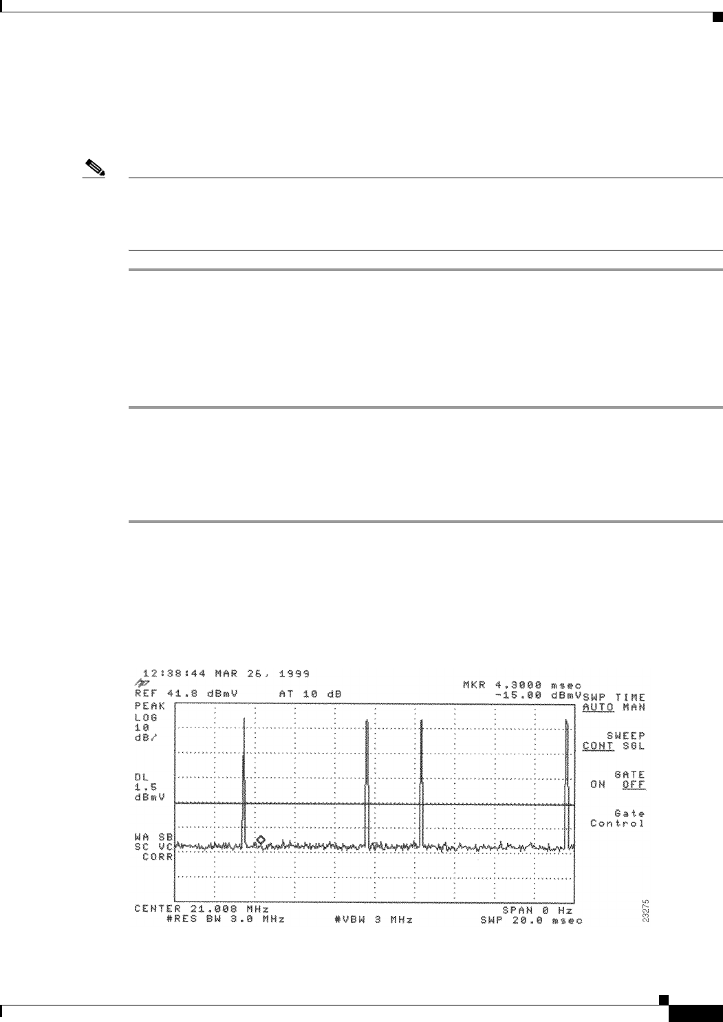
4-25
Cisco uBR7225VXR Universal Broadband Router Hardware Installation Guide
OL-17309-02
Chapter 4 Connecting the Cisco uBR7225VXR Router to the Cable Headend
Measuring the Upstream RF Signal
Step 10 Verify that your headend RF measurements meet the recommended DOCSIS parameters listed in the
tables in Appendix B, “RF Specifications.”
Step 11 Record your headend settings in Appendix G, “Site Log.” This will assist in troubleshooting the
Cisco uBR7225VXR universal broadband router installation later in the process.
Note Be sure not to narrow the focus of your analysis any further than approximately 3-MHz channel width.
Doing so can yield incorrect readings. For example, if you were to view an upstream RF signal with a
resolution bandwidth of only 300 kHz and a video channel bandwidth of only 100 kHz, your
measurements would register lower than the actual transmission levels.
Analyzing the Upstream RF Signal
When you have set up your spectrum analyzer to accurately read the upstream RF signal, you can verify
that a remote cable modem is operating as it should by pinging the modem via a console terminal.
Step 1 Log in to your Cisco uBR7225VXR universal broadband router with a console terminal.
Step 2 Adjust the sweep time on your spectrum analyzer to 20 microseconds.
Step 3 Ping the remote cable interface card using first a 64-byte, then a 1500-byte ping packet request, and take
note of the upstream RF signal in each case. Several hundred or thousand ping packets might be required
for a usable pattern to emerge.
Figure 4-29 and Figure 4-30 provide two examples of an ideal upstream RF signal based on a simple 64-
or 1500-byte ping of a single remote cable interface. The more slender of the data spikes in the RF signal
(the first and third spikes in Figure 4-29) are bandwidth request packet transmissions, while the larger
spikes are the actual 64- or 1500-byte ping packet returns.
Figure 4-29 Analyzing the Upstream RF Signal—64-Byte Data Packets
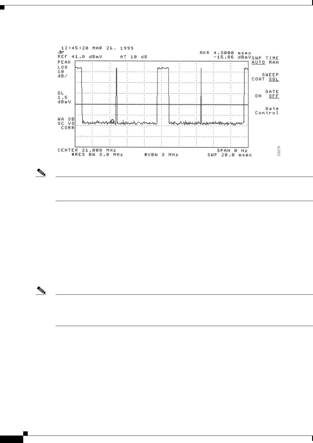
4-26
Cisco uBR7225VXR Universal Broadband Router Hardware Installation Guide
OL-17309-02
Chapter 4 Connecting the Cisco uBR7225VXR Router to the Cable Headend
Measuring the Upstream RF Signal
Figure 4-30 Analyzing the Upstream RF Signal—1500-Byte Data Packets
Note Both of the previous examples feature 16-QAM transmission with a channel width of 3.2 MHz, yielding
a 10-Mbit/sec data rate. In addition, these examples have an optimal upstream carrier-to-noise ratio of
approximately 50 dB.
Now it is time to view your upstream RF signal with multiple remote cable modems. Figure 4-31 and
Figure 4-32 both display upstream RF signals encompassing more than one remote cable modem. In
each case, there are two bandwidth requests followed by their respective ping packet returns, both at
slightly different amplitudes. This situation is most commonly caused by a difference in the receive
power from the two cable modems in question. In the example, the remote cable modem with the lesser
amplitude is “cable modem A” and the other is “cable modem B.”
In the following example, cable modem A and cable modem B have been artificially configured to yield
a larger than normal difference in amplitude between their respective upstream RF transmissions. Under
normal conditions, the maximum difference in amplitude between any cable modems will be about
1.5 dB. Differences greater than 1.5 dB indicate a possible cable plant or remote cable modem problem.
Note To further illustrate this point, you can log in to your Cisco uBR7225VXR router using a console
terminal and enter the show cable modem command to obtain a report of the receive power ratings for
each modem. In the example, the receive power ratings for remote cable modems A and B are –2 dBmV
and 0 dBmV, respectively.
The two bandwidth requests and ping packet returns on the upstream RF signal for cable modems A and
B are slightly different in Figure 4-31 and Figure 4-32. Differences in the distance between bandwidth
requests are primarily caused by the contention-based nature of multiple remote cable modems on the
same line. Differences in the distance between ping packet returns are primarily caused by factors such
as packet size and system loading.
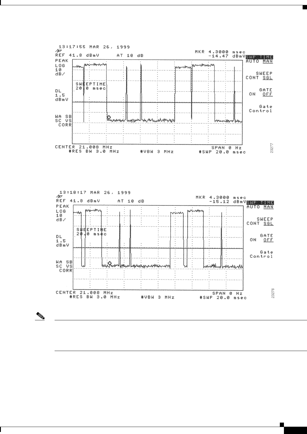
4-27
Cisco uBR7225VXR Universal Broadband Router Hardware Installation Guide
OL-17309-02
Chapter 4 Connecting the Cisco uBR7225VXR Router to the Cable Headend
Measuring the Upstream RF Signal
Figure 4-31 Analyzing the Upstream RF Signal—Multiple Active Remote Cable Modems (A)
Figure 4-32 Analyzing the Upstream RF Signal—Multiple Active Remote Cable Modems (B)
Note When viewing the upstream RF signal on your spectrum analyzer, two ping packet returns (for example,
from remote cable modems A and B) can be so close together that they appear to be one rather large
packet with a slight jump or decline in amplitude halfway through the measurement. This is an indication
that the upstream is 100 percent occupied during this time.
Figure 4-33 shows an upstream RF signal from a remote cable modem in a “real-life” scenario including
outside plant noise. Notice the relatively tall spike at the very left edge of the ping packet return. This
spike is mainly additive noise associated with an upstream RF signal mired by excessive amounts of
severe outside plant noise (as in this example). In addition, notice that the carrier-to-impulse noise ratio
measurement between the two diamond-shaped markers is only about 12 dB. (A few other noise peaks
are even worse.)
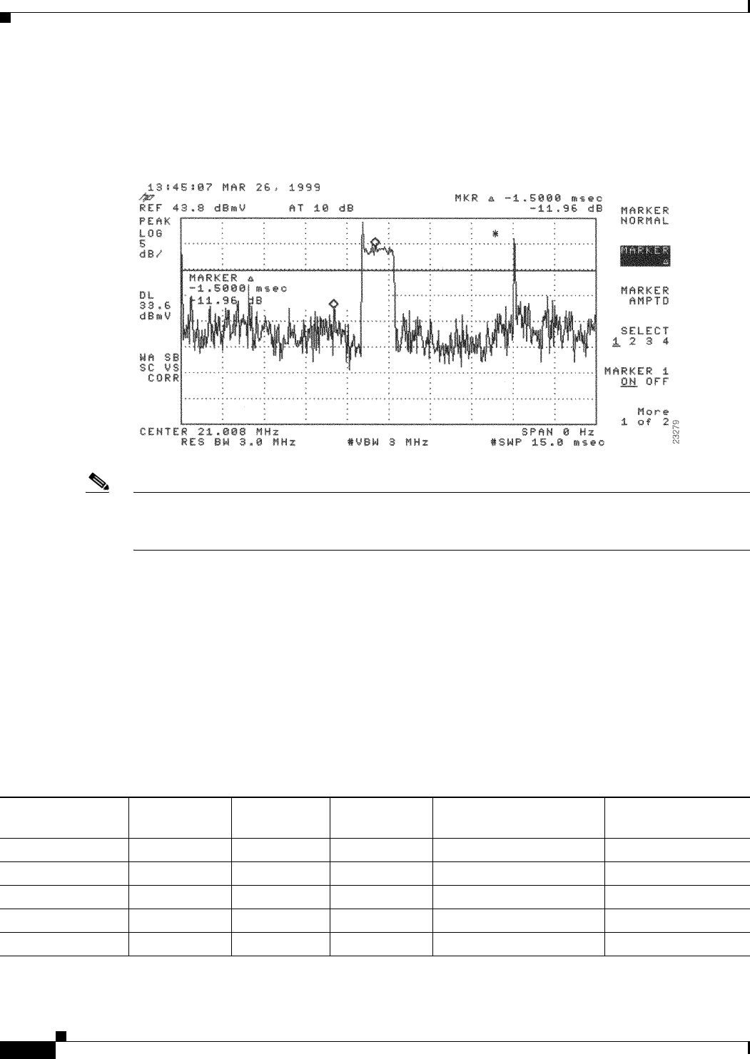
4-28
Cisco uBR7225VXR Universal Broadband Router Hardware Installation Guide
OL-17309-02
Chapter 4 Connecting the Cisco uBR7225VXR Router to the Cable Headend
Measuring the Upstream RF Signal
The importance of this example is to bring to your attention the need for minimal outside plant noise.
Time-varying, fast noise can cause bit errors in packet transmissions, rendering your communication link
unreliable, if not unusable.
Figure 4-33 Analyzing the Upstream RF Signal—Outside Plant Noise Included
Note This illustration depicts an upstream RF signal whose carrier-to-impulse noise ratio does not meet
DOCSIS 1.0 specifications. The data packet in Figure 4-33 was “dropped” due to severe noise
interference with a more narrow resolution bandwidth.
Using the Zero-Span Method with Adjacent Upstream Channels
When measuring upstream signals using the zero-span method, a very wide resolution and video
bandwidth give very accurate readings, but render your readings susceptible to energy in adjacent
channels. As the number of upstream services increases, so does the likelihood of interference from
adjacent channels. This section describes using the zero-span power measurement method, with a more
narrow resolution bandwidth.
Simply narrowing the resolution bandwidth will not yield accurate readings. See Table 4-2.
Table 4-2 Sample Channel Width and Symbol Rate Combinations with Their Respective Minimum Resolution
Bandwidth Measurements
Center Frequency Channel Width Symbol Rate
1/2
Symbol Rate
Center Frequency
+/–1/2 Symbol Rate
Minimum Resolution
Bandwidth
20.000 200 kHz 160 80 20.080 and 19.020 MHz 10 kHz
30.000 400 kHz 320 160 30.160 and 29.840 MHz 30 kHz
40.000 800 kHz 640 320 40.320 and 39.680 MHz 100 kHz
25.000 1.6 MHz 1280 640 25.640 and 24.360 MHz 100 kHz
28.000 3.2 MHz 2560 1280 29.280 and 27.720 MHz 300 kHz
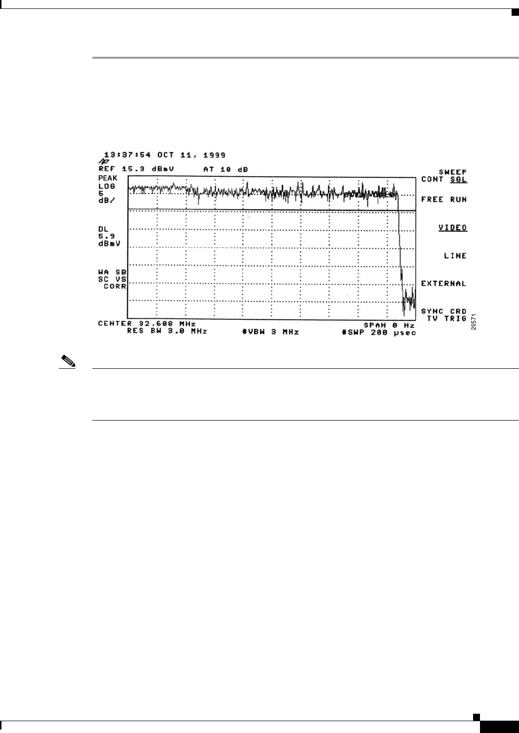
4-29
Cisco uBR7225VXR Universal Broadband Router Hardware Installation Guide
OL-17309-02
Chapter 4 Connecting the Cisco uBR7225VXR Router to the Cable Headend
Measuring the Upstream RF Signal
Step 1 Display a signal complete with preamble and upstream data transmission information similar to the
resulting signal from Step 3 through Step 10 under the “Measuring the Upstream RF Signal Using a
Spectrum Analyzer” section on page 4-22. Your spectrum analyzer should display a signal similar to the
one in Figure 4-34.
Figure 4-34 Preamble Amplitude Before Resolution and Video Bandwidth Reduction
Note Figure 4-34 is a display from a standard spectrum analyzer. The following figures, Figure 4-35 through
Figure 4-38, are taken from a vector signal analyzer. If you do not have access to a vector signal analyzer,
or want to skip the following section describing its use when viewing your upstream signal, proceed to
Step 3.
Step 2 (Optional) View your upstream signal using a vector signal analyzer such as the Agilent 89441A.
The advantage of displaying these signals with the vector signal analyzer is that you can view them over
the time domain for a specified time interval. In addition, the vector signal analyzer enables you to
measure the digital channel power of a very short duration data transmission, like the preamble of a
digital signal.
a. Set up your vector signal analyzer to view both the “frequency” domain and “time” domain of your
upstream signal. Your vector signal analyzer should display a pair of signals similar to those in
Figure 4-35.
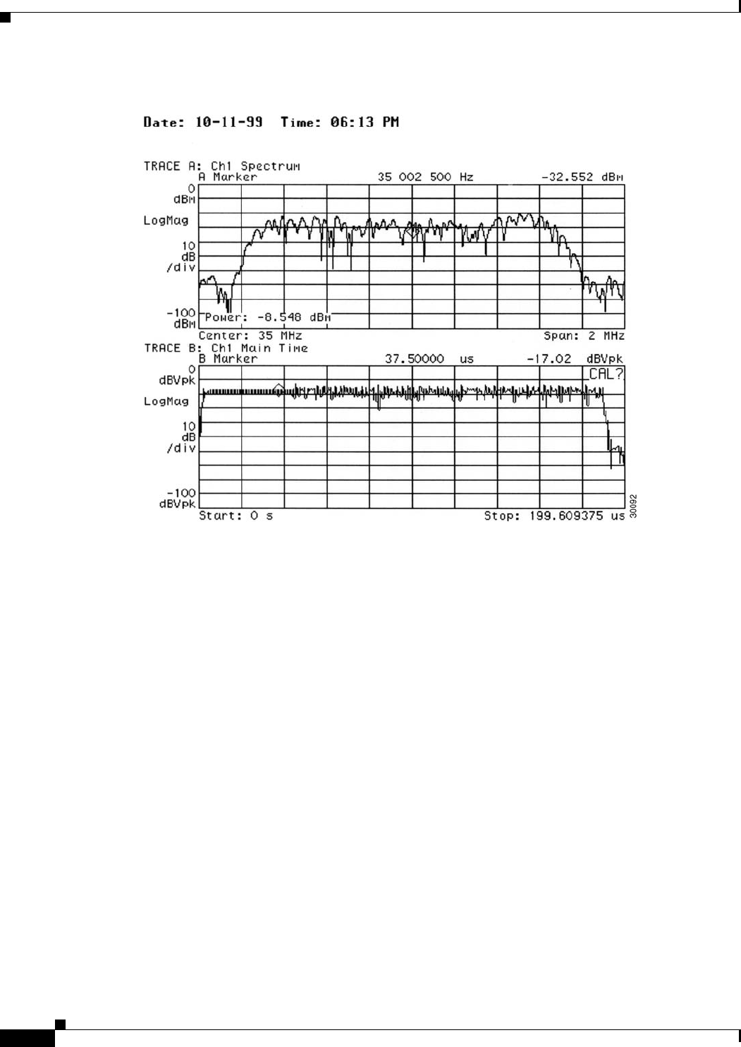
4-30
Cisco uBR7225VXR Universal Broadband Router Hardware Installation Guide
OL-17309-02
Chapter 4 Connecting the Cisco uBR7225VXR Router to the Cable Headend
Measuring the Upstream RF Signal
Figure 4-35 Vector Signal Analyzer Plot of Upstream Data Burst
The upper graph in Figure 4-35 represents the frequency domain and the lower graph represents the
time domain.
In the time domain, the channel power of the preamble of a digital upstream signal is not spread
across the entire channel. However, the channel power of the remainder of the digital transmission
is spread across the entire channel. Even though it may not seem so, the total channel power across
both the preamble and the subsequent data segment remains constant.
b. Narrow the view on your vector signal analyzer to display only the preamble of the digital data
signal in both the frequency domain and time domain.
The upper display in Figure 4-36 is a plot of only the preamble portion of the digital signal in
Figure 4-35. Notice how the amplitude of the signal experiences many “peaks” and “valleys.” When
you are measuring the preamble power using the zero-span method, be sure that you measure the
actual signal energy (a peak), rather than accidentally measuring the power level of a valley in the
preamble.
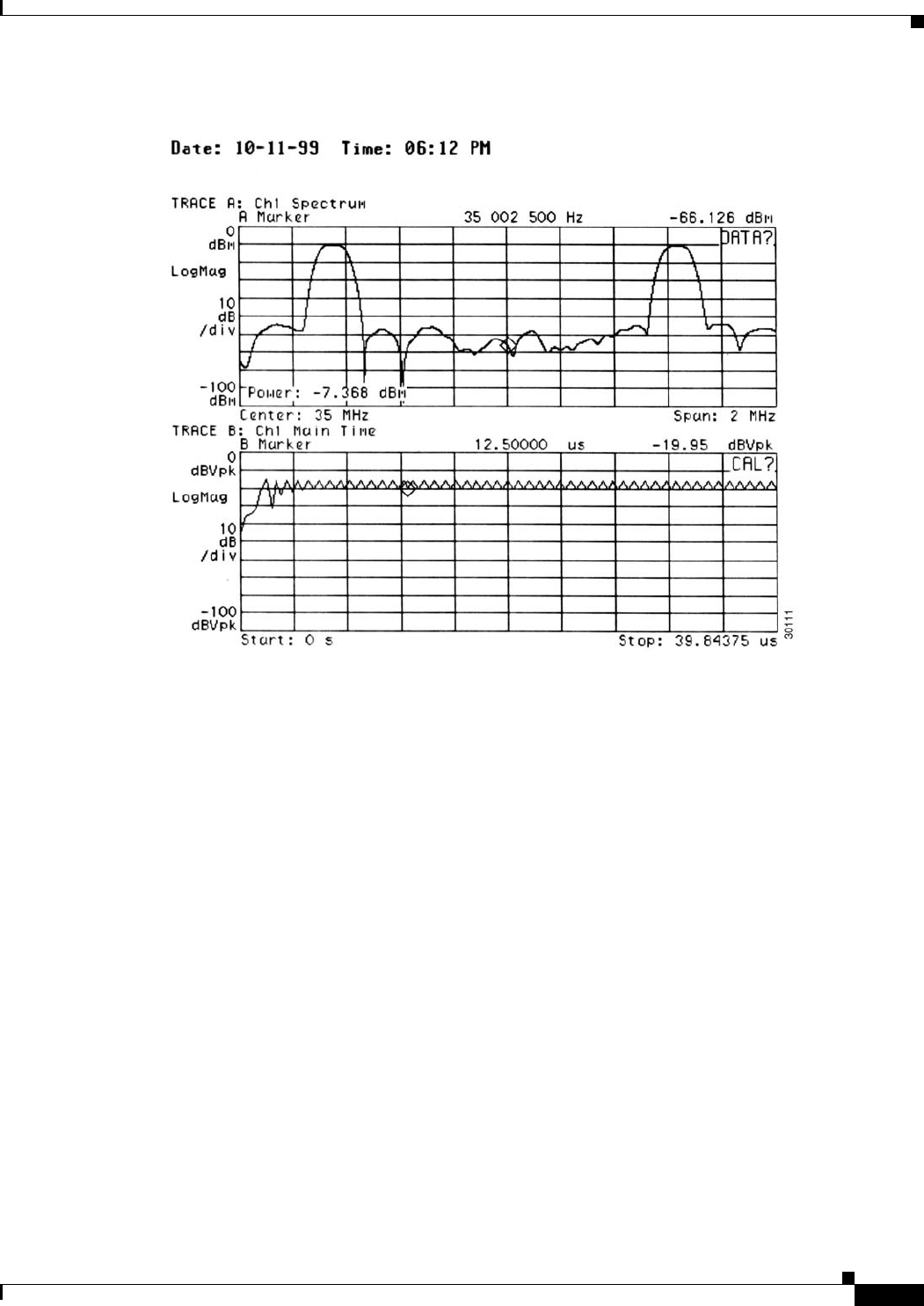
4-31
Cisco uBR7225VXR Universal Broadband Router Hardware Installation Guide
OL-17309-02
Chapter 4 Connecting the Cisco uBR7225VXR Router to the Cable Headend
Measuring the Upstream RF Signal
Figure 4-36 Vector Signal Analyzer Plot of Upstream Data Burst (Preamble Only)
Figure 4-35 and Figure 4-36 illustrate the benefit of properly adjusting the center frequency of your
spectrum analyzer to enable the power measurement of the preamble to match the power
measurement of the rest of the digital transmission.
Figure 4-35 and Figure 4-36 show how adjusting the spectrum analyzer in the time domain reveals
this frequency domain phenomenon. The spectrum analyzer is unable to capture the data as shown
in the vector signal analyzer plots.
The power level in the upstream channel fluctuates by approximately 1 dB between Figure 4-35 and
Figure 4-36. This difference is within both the measurement tolerance of the vector signal analyzer
and the accuracy requirement for any DOCSIS-based cable modem.
c. Switch your vector signal analyzer over to Digital Demodulation Mode. Your vector signal analyzer
displays a set of screens similar to those in Figure 4-37.
Using this mode to view your upstream signal allows you to view the same time and frequency
domain information found in Figure 4-36, as well as the upstream signal’s phase characteristics,
shown in the bottom-right portion of the vector signal analyzer display screen.
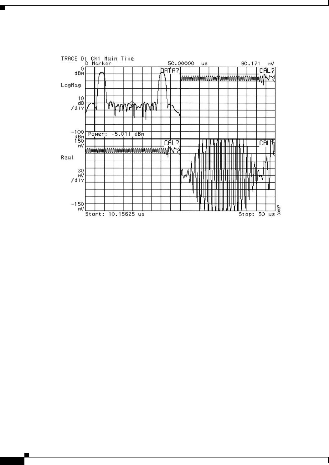
4-32
Cisco uBR7225VXR Universal Broadband Router Hardware Installation Guide
OL-17309-02
Chapter 4 Connecting the Cisco uBR7225VXR Router to the Cable Headend
Measuring the Upstream RF Signal
Figure 4-37 Vector Signal Analyzer Plot of Upstream Data Burst (Preamble Only)—QPSK
Demodulation Mode
d. Switch your vector signal analyzer over to quaternary phase shift keying (QPSK) demodulation
mode. Your vector signal analyzer will display a set of screens similar to those in Figure 4-38.
Figure 4-38 displays the QPSK demodulation information for the same upstream signal as in
Figure 4-37. However, there are some notable differences in the information presented. For example,
notice that the constellation and transition graphs (top and bottom left) both indicate only two of the
four QPSK data points handling any bits. Because this graph is covering only the preamble of the
data transmission, you get to see only a portion of the whole signal performance. (If you were to
view the entire signal transmission in this mode, all four QPSK data points would display bits.)

4-33
Cisco uBR7225VXR Universal Broadband Router Hardware Installation Guide
OL-17309-02
Chapter 4 Connecting the Cisco uBR7225VXR Router to the Cable Headend
Measuring the Upstream RF Signal
Figure 4-38 Vector Signal Analyzer Plot of Upstream Data Burst (Preamble Only)—Digital
Demodulation Mode
Note Before moving on to Step 3, be sure to hook your spectrum analyzer back up to the upstream signal
source.
Step 3 On your spectrum analyzer, narrow both the resolution and video bandwidth to 1 MHz. You will notice
that the preamble of the signal has dropped in amplitude, yielding a spectrum analyzer display similar
to the one in Figure 4-39.
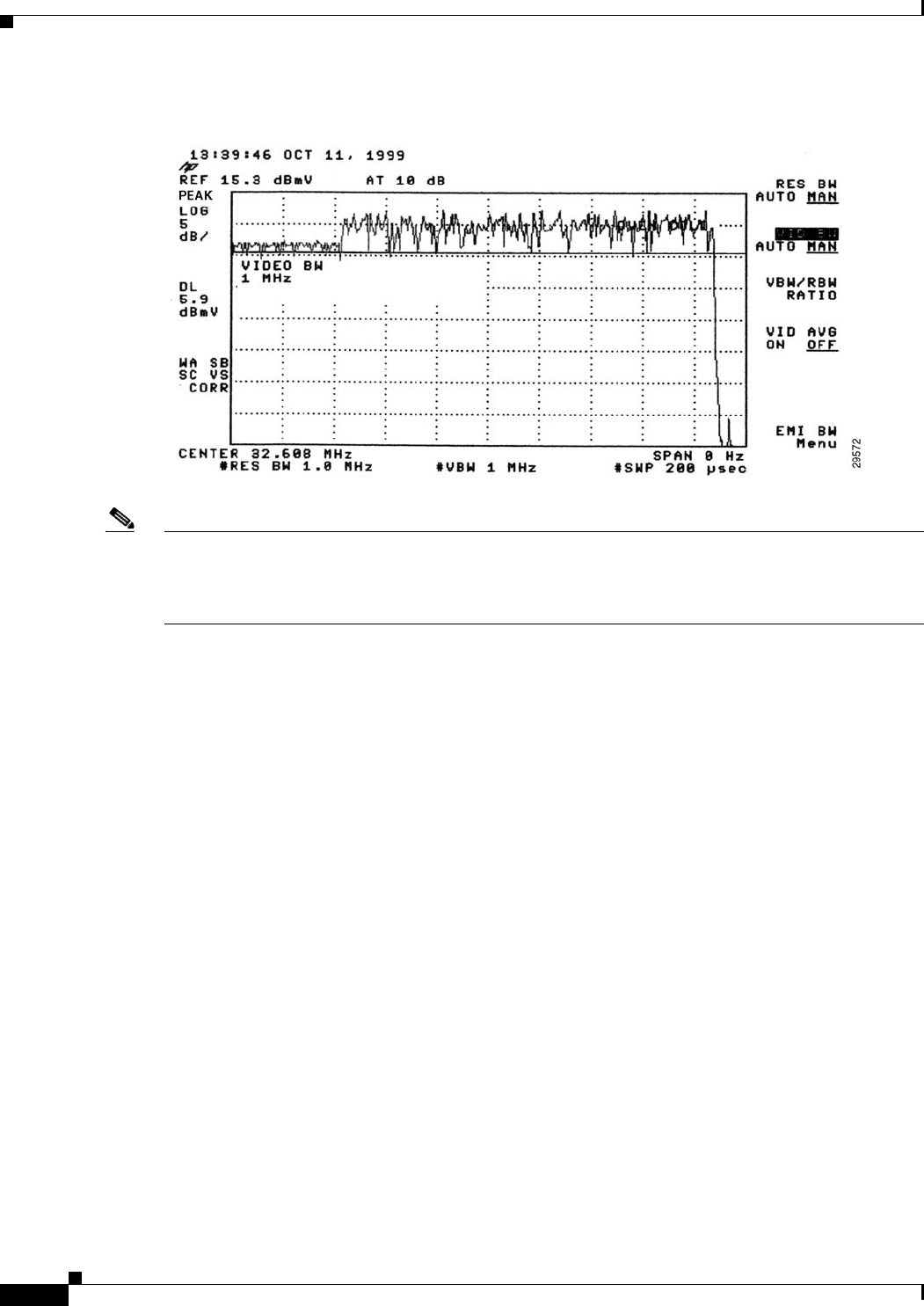
4-34
Cisco uBR7225VXR Universal Broadband Router Hardware Installation Guide
OL-17309-02
Chapter 4 Connecting the Cisco uBR7225VXR Router to the Cable Headend
Measuring the Upstream RF Signal
Figure 4-39 Preamble Amplitude Before Center Frequency Adjustment
Note The slight amplitude variations shown in these figures are normal signal level variations between bursts
in the upstream channel. Expect modems to vary upstream transmit power by nearly 1 dB between
bursts. This is well within the requirements for DOCSIS compliance. The default variation between
modems is up to 1.5 dB for most DOCSIS CMTS equipment.
Step 4 Using the examples in Table 4-2 on page 4-28 as a basis for the formula, calculate the correct center
frequency offset necessary to measure the preamble peak power when viewed in a narrow bandwidth.
In the example, the channel width is 1.6 MHz, which has a symbol rate of 1280 ksym/sec; therefore, the
appropriate offset value is 640 kHz.
Step 5 Change the center frequency on the spectrum analyzer by this offset value (33.248 MHz in the example)
and check to see that the preamble has regained its lost amplitude by comparing it to the amplitude of
the rest of the signal. If so, the spectrum analyzer should display a signal similar to the one in
Figure 4-40.
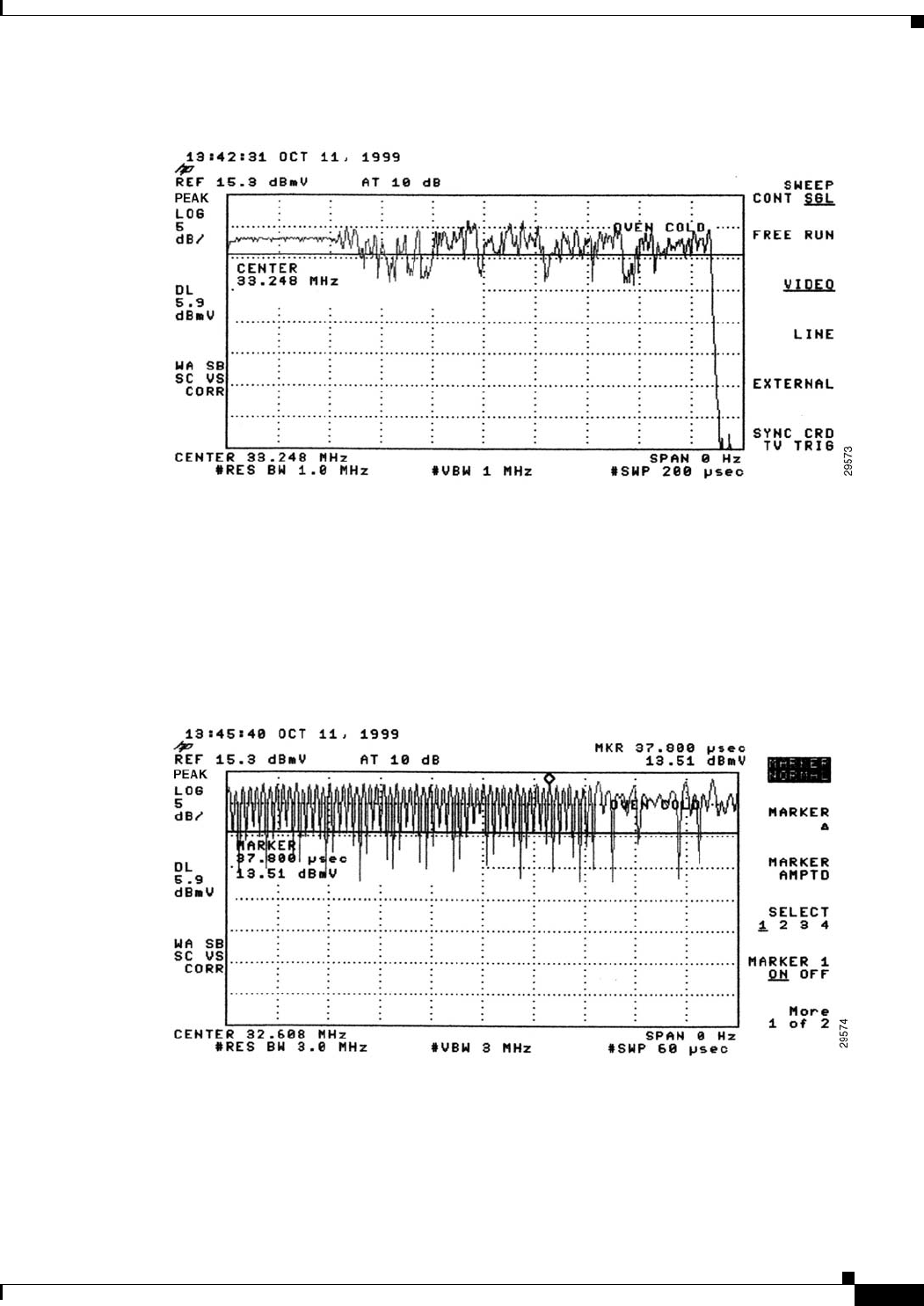
4-35
Cisco uBR7225VXR Universal Broadband Router Hardware Installation Guide
OL-17309-02
Chapter 4 Connecting the Cisco uBR7225VXR Router to the Cable Headend
Measuring the Upstream RF Signal
Figure 4-40 Preamble Amplitude Recovery After Center Frequency Adjustment
To get an even better look at the patterns and dramatic shifts in amplitude within the preamble itself, you
can accelerate the sweep time for your zero-span signal processing.
Step 6 Tune the spectrum analyzer to the original center frequency (32.608 MHz in this example).
Step 7 Reset both the resolution and video bandwidth of the signal back to 3 MHz, but reduce the sweep time
from 200 microseconds to 60 microseconds. The resulting display, similar to Figure 4-41, clearly shows
the “tight” pattern of the preamble stretched across three-quarters of the spectrum analyzer display.
Figure 4-41 Original Preamble Viewed with Accelerated Sweep Time
Step 8 Change the center frequency back to 33.248 MHz and both the resolution and video bandwidth values
to 1 MHz, retaining the new sweep time of 60 microseconds. The peak amplitude is clearly displayed
with approximately 4.25 dB difference between the preamble and the rest of the upstream data
transmission. (See Figure 4-42.)
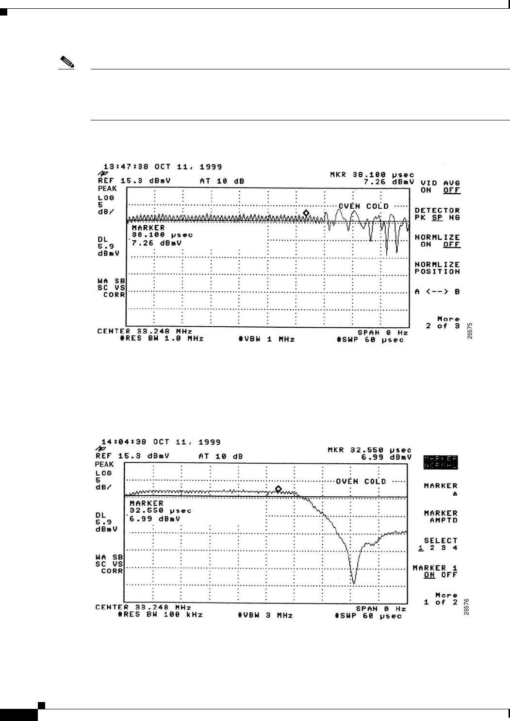
4-36
Cisco uBR7225VXR Universal Broadband Router Hardware Installation Guide
OL-17309-02
Chapter 4 Connecting the Cisco uBR7225VXR Router to the Cable Headend
Measuring the Upstream RF Signal
Note The 4.25 dB decrease in amplitude is due to a combination of half of the channel bandwidth (3 dB) and
an additional 1.25 dB decrease attributed to the digital channel filter mask, known as the “alpha.” The
value of alpha is 25 percent of an upstream DOCSIS channel’s width, and the peak signal energy spread
across the entire upstream channel width.
Figure 4-42 Preamble with Decreased Amplitude and Condensed Sweep Time
Step 9 Narrow the resolution bandwidth from 1 MHz to 100 kHz and increase the video bandwidth to 3 MHz,
still retaining the 60 microseconds sweep time. Your spectrum analyzer should display a signal similar
to Figure 4-43.
Figure 4-43 Very Narrow Resolution Bandwidth Limits Range of Spectrum Analysis

4-37
Cisco uBR7225VXR Universal Broadband Router Hardware Installation Guide
OL-17309-02
Chapter 4 Connecting the Cisco uBR7225VXR Router to the Cable Headend
Measuring the RF Signal at the Forward Test Point on a Laser Transmitter
Note The slight “ramp-up” at the beginning of the preamble when viewed in this mode is attributed to the time
required to charge the spectrum analyzer’s detector circuit.
Figure 4-43 shows a smooth and easily measured signal amplitude, providing accurate measurement of
a very fast burst upstream carrier. You can compare the measurements obtained using a spectrum
analyzer with those of specialized test equipment. In general, the readings from the spectrum analyzer
will be within 1 to 2 dB of the (more expensive) specialized equipment. Because 1 to 2 dB is well within
the calibration accuracy of spectrum analyzers, you can reliably use these procedures in the cable
headend environment.
Measuring the RF Signal at the Forward Test Point on a Laser
Transmitter
This section describes RF signal measurements that should be taken with a spectrum analyzer at the
downstream forward test point on the fiber-optic laser transmitter.
Use the following steps to measure the downstream forward test point on the fiber-optic laser transmitter:
Step 1 Connect the spectrum analyzer to the downstream forward test point on the fiber-optic laser transmitter.
Figure 4-44 shows a typical measurement of the downstream forward test point.
Figure 4-44 Measuring the RF Signal at the Downstream Forward Test Point on the
Laser Transmitter
Step 2 Using the spectrum analyzer zoom feature, zoom the display on the first individual video channel. In the
example in Figure 4-45, the first video channel is channel 48.
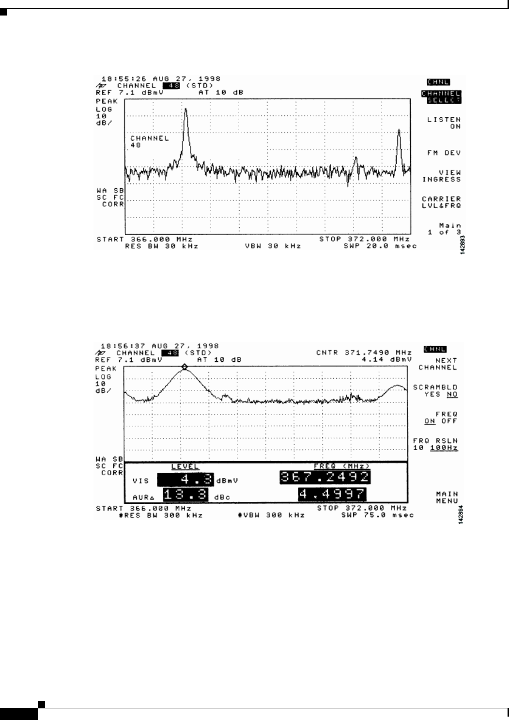
4-38
Cisco uBR7225VXR Universal Broadband Router Hardware Installation Guide
OL-17309-02
Chapter 4 Connecting the Cisco uBR7225VXR Router to the Cable Headend
Measuring the RF Signal at the Forward Test Point on a Laser Transmitter
Figure 4-45 Downstream Forward Test Point on the Laser Transmitter—Video Channel Display
Step 3 Select the carrier level (or amplitude) function. Figure 4-46 shows the detailed display of the analog
carrier level and frequency screen for the channel 48 (in this example).
Figure 4-46 Downstream Forward Test Point on the Laser Transmitter—Detailed Video Channel
Display
Step 4 Return to the main menu on your spectrum analyzer.
Step 5 Select a digital channel to measure. In the example in Figure 4-47, the digital channel shown is
channel 50.
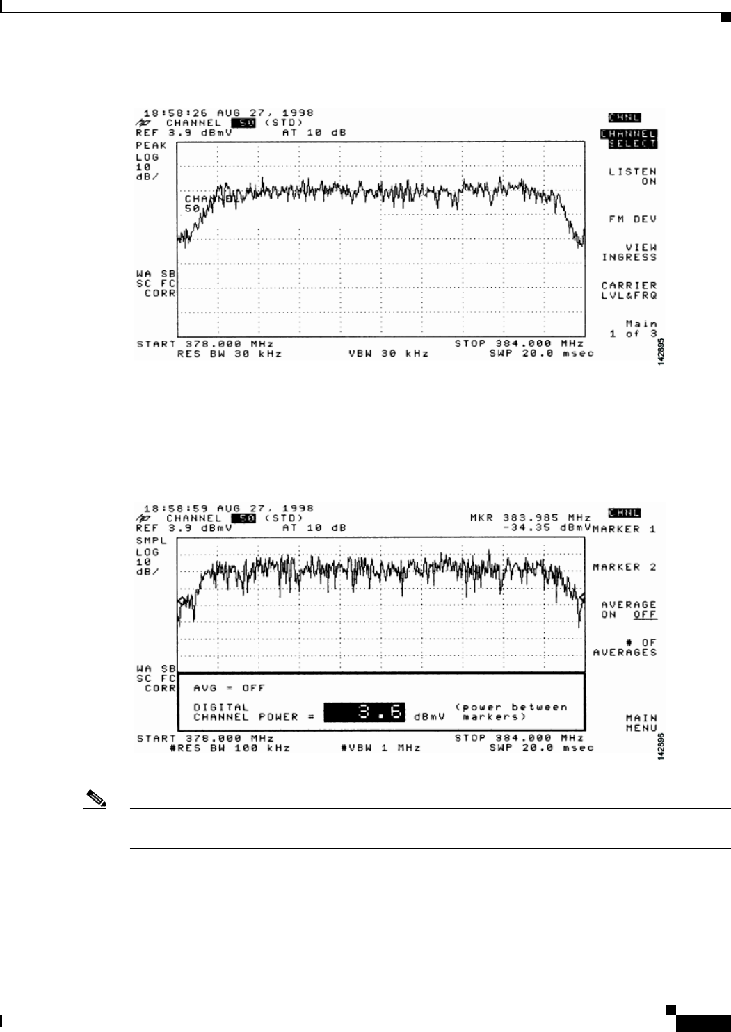
4-39
Cisco uBR7225VXR Universal Broadband Router Hardware Installation Guide
OL-17309-02
Chapter 4 Connecting the Cisco uBR7225VXR Router to the Cable Headend
Measuring the RF Signal at the Forward Test Point on a Laser Transmitter
Figure 4-47 Downstream Forward Test Point on the Laser Transmitter—Digital Channel Display
Step 6 Go to the main menu on the spectrum analyzer and advance the screen displays (next screen) until the
digital channel power display is shown. (See Figure 4-48.)
Figure 4-48 Downstream Forward Test Point on the Laser Transmitter—Digital Channel Power
Display
Note The +3.6 dBmV digital power rating is nearly the same as the previously measured video carrier level
(+4.3 dBmV). This value is too high to provide reliable digital data transmission.
Step 7 Set the upconverter output level so that the amplitude of the digitally modulated carrier is 6 dB to 10 dB
below the amplitude found on the same frequency on an analog TV channel.
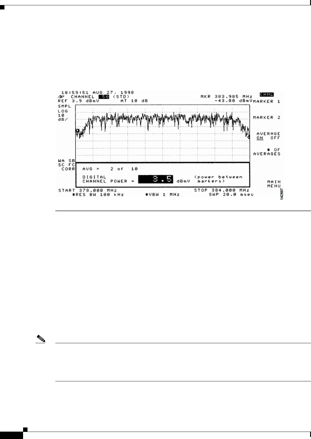
4-40
Cisco uBR7225VXR Universal Broadband Router Hardware Installation Guide
OL-17309-02
Chapter 4 Connecting the Cisco uBR7225VXR Router to the Cable Headend
Configuring the Digital Signal
Step 8 Select the video averaging feature to verify flatness through the headend combiner. After 10 averages,
the power rating decreases by approximately 2.5 dB from actual digital channel power. While video
averaging is in progress, your spectrum analyzer should display a signal similar to the one shown in
Figure 4-49.
Figure 4-49 Downstream Forward Test Point on the Laser Transmitter—Digital Channel Display
Using Video Averaging
Configuring the Digital Signal
After you have configured the RF signal, you must configure the digital data signal that will be carried
between the Cisco uBR7225VXR universal broadband router and cable modems.
We recommend installing a Cisco uBR900 series cable access router at the headend to verify the digital
data configuration. For instructions on how to install a Cisco uBR900 series access router, refer to the
installation and configuration guides for the Cisco uBR900 series access router that you are using at the
following URL:
https://www.cisco.com/en/US/products/hw/cable/ps2221/index.html
The output of the Cisco uBR7225VXR router is measured in RF signals through an internal upconverter.
Upconverter output levels should be set to carry the digital signal data at 6 to 10 dB below the adjacent
analog video signal. The value chosen is at the discretion of each cable operator.
Note The value chosen for the digital data in relation to the adjacent video signal must be made available to
field technicians installing DOCSIS cable modem.
At a cable interface connection, this value can be measured to verify the correct operation of the
cable interface.

4-41
Cisco uBR7225VXR Universal Broadband Router Hardware Installation Guide
OL-17309-02
Chapter 4 Connecting the Cisco uBR7225VXR Router to the Cable Headend
Configuring the Digital Signal
Careful system design and operation can prevent potentially serious intermittent performance problems
across your cable interface network. Each cable operator should make use of the following guidelines
and practices to ensure reliable operation of any 64-QAM based digital network:
•“NCTA Recommended Practices for Measurements on Cable Television Systems”
(http://www.ncta.com)
•Part 76 of the FCC Rules and Regulations (http://transition.fcc.gov/oet/info/rules/)
•DOCSIS 1.0 RF Interface Specification (http://www.cablemodem.com)
•DOCSIS 1.1 RF Interface Specification
(http://www.cablelabs.com/specifications/CM-SP-RFIv1.1-C01-050907.pdf)
For example, if your headend overdrives the fiber-optic lasers transmitters, in either the upstream or
downstream path, clipping may occur. Laser clipping leads to degraded signal integrity. In minor doses,
this signal damage is not immediately visible on an analog video signal, but it can completely disrupt
the digital transmission path. (That is, digital signals are more sensitive to clipping than analog signals
and will more readily display the negative effects of laser clipping.)
If a digital signal employing forward error correction (FEC) is near its impairment limit, it is very
susceptible to changes in signal level—on the order of as little as 0.1 dB. If there is no amplitude margin
available in the transmission path between the headend and any one cable modem, the typical signal level
variations of a properly functioning cable system (3 to 6 dB) can create intermittent service outages that
are difficult to isolate.
Typical CATV measurement equipment, such as digital signal level meters, measure to an accuracy of
+/–1 dB. However, some older analog meters only measure to an accuracy of +/–3 dB; therefore,
maintaining 6-dB margins above the minimum levels can provide reliable long-term service.

4-42
Cisco uBR7225VXR Universal Broadband Router Hardware Installation Guide
OL-17309-02
Chapter 4 Connecting the Cisco uBR7225VXR Router to the Cable Headend
Configuring the Digital Signal

CHAPTER
5-1
Cisco uBR7225VXR Universal Broadband Router Hardware Installation Guide
OL-17309-02
5
Maintaining the Cisco uBR7225VXR Router
This chapter describes basic maintenance for the Cisco uBR7225VXR universal broadband router and
contains the following sections:
•Online Insertion and Removal, page 5-1
•Environmental Monitoring and Reporting Functions, page 5-2
Online Insertion and Removal
The cable interface line cards and network processing engine in the Cisco uBR7225VXR universal
broadband router support online insertion and removal (OIR). Technically, the Cisco uBR7225VXR
universal broadband router supports true OIR, or “hot swapping,” of cable interface line cards only when
exchanging cable interface line cards of the exact same type (for example, exchanging a
Cisco uBR-MC28U line card for another Cisco uBR-MC28U line card). Under these conditions, no
reload of the router is required.
You can remove and replace a cable interface line card with the same type of component without
interrupting the system. This function allows you to install and replace the same type of cable interface
cards while the router is operating.
Note To replace a cable interface line card with a different type of line card (for example, hot swapping from
a Cisco uBR-MC16U to a Cisco uBR-MC28U, you must copy your startup configuration to your running
configuration on the Cisco uBR7225VXR router to enable the interfaces on the new cable interface line
card.
Caution When you use OIR for different types of cable interface line cards (for example, a Cisco uBR-MC16U
line card replaced by a Cisco uBR-MC28U line card), you might have to reconfigure the interfaces, and
we highly recommend that you reload the router.
Detailed instructions for installing Cisco cable interface cards are contained in the document
Cisco uBR7200 Series Cable Interface Line Card Hardware Installation Guide at the following URL:
http://www.cisco.com/en/US/docs/interfaces_modules/cable/line_cards/installation/guide/mcxxfru.htm
l

5-2
Cisco uBR7225VXR Universal Broadband Router Hardware Installation Guide
OL-17309-02
Chapter 5 Maintaining the Cisco uBR7225VXR Router
Environmental Monitoring and Reporting Functions
Caution The network processing engine cannot be removed if the router is operating. Removing the network
processing engine while the Cisco uBR7225VXR router is operating causes the router to shut down or
crash, and might damage or destroy memory files.
Each cable interface line card has a bus connector that connects it to the router’s midplane. Each
midplane connector has a set of tiered pins in three lengths. The pins send specific signals to the system
as they make contact with the cable interface line card. The system assesses the signals it receives and
the order in which it receives them to determine if a board is being removed or inserted into the midplane.
From these signals, the system determines whether to reinitialize a new interface or shut down a removed
interface. For example, when inserting a cable interface line card, the longest pins make contact with the
cable interface line card first, and the shortest pins make contact last. The system recognizes the signals
and the sequence in which it receives them.
When you remove or insert a cable interface line card in a Cisco uBR7225VXR router, the midplane pins
send signals to notify the system, which then does the following:
1. Rapidly scans the midplane for configuration changes.
2. Initializes all newly inserted cable interface line cards, noting any removed interfaces and placing
them in the administratively shutdown state.
3. Brings all previously configured interfaces on the cable interface line card back to the state they
were in when it was removed. If the same type of interface card type is reinserted into a slot, its
interfaces are configured and brought online up to the interface count of the original cable interface
line card. If, however, any new interfaces are put in the administratively shutdown state, as if they
were present (but not configured) at boot time, the system must be configured.
Environmental Monitoring and Reporting Functions
Environmental monitoring and reporting functions are controlled by the network processing engine and
allow you to maintain normal system operation by identifying and resolving adverse conditions before
loss of operation. The environmental monitoring functions constantly monitor the internal chassis air
temperature and AC supply voltages. Each power supply monitors its own voltage, currents, and
temperature and shuts itself down if it detects a critical condition within the power supply. If conditions
reach shutdown thresholds, the system shuts down to avoid equipment damage from excessive heat. The
reporting functions periodically log the values of measured parameters so that you can retrieve them for
analysis later, and the reporting functions display warnings on the console if any of the monitored
parameters exceed defined thresholds.
Environmental Monitoring
The environmental monitoring functions use the following five levels of status conditions to monitor the
system. Two sensors on the network processing engine monitor the temperature of the cooling air as it
moves through the chassis.
•Normal—All monitored parameters are within normal tolerances.
•Warning—The system has exceeded a specified threshold. The system continues to operate, but we
recommend operator action to bring the system back to a normal state.
•Critical—An out-of-tolerance temperature or voltage condition exists. The system continues to
operate; however, the system is approaching shutdown. Immediate operator action is required.

5-3
Cisco uBR7225VXR Universal Broadband Router Hardware Installation Guide
OL-17309-02
Chapter 5 Maintaining the Cisco uBR7225VXR Router
Environmental Monitoring and Reporting Functions
•Shutdown—The processor has detected a temperature condition that could result in physical damage
to system components and has disabled DC power to all internal components. Requires immediate
operator action. Before any shutdown, the system logs the status of monitored parameters in
NVRAM so that you can retrieve it later to help determine the cause of the problem. The power
supply repeatedly attempts to restart itself within 90 seconds to clear the temperature condition.
•Power supply shutdown—The power supply detected an internal out-of-tolerance overvoltage,
overcurrent, or temperature condition and shut itself down. The power supply repeatedly attempts
to restart itself within 90 seconds to clear the shutdown condition.
Table 5-1 lists the temperature thresholds for the processor-monitored levels.
Temperature sensors are located on the NPE Inlet and NPE Outlet. See the appropriate chapter for your
NPE in the Network Processing Engine and Network Services Engine Installation and Configuration
document for their exact locations. Temperature MP NPE Inlet is located on NPE side of the inlet edge
of the midplane. Temperature MP LC Inlet is located on line card side of the inlet edge of the midplane.
Temperature MP NPE is located on NPE side of the middle of the midplane. Temperature MP LC is
located on line card side of the middle of the midplane.
If the air temperature exceeds a defined threshold, the system controller displays warning messages on
the console terminal and, if the temperature exceeds the shutdown threshold, it shuts down the system.
The system stores the present parameter measurements for both temperature and DC voltage in NVRAM
so that you can retrieve them later as a report of the last shutdown parameters.
The power supplies monitor internal power supply temperature and voltages. A power supply is either
within tolerance (normal) or out of tolerance (critical). If an internal power supply temperature or
voltage reaches a critical level, the power supply shuts down without any interaction with the system
processor.
Reporting Functions
The Cisco uBR7225VXR router displays warning messages on the console if chassis
interface-monitored parameters exceed a desired threshold. You can also retrieve and display
environmental status reports with the show environment, show environment all, show environment
last, and show environment table commands. Parameters are measured and reporting functions are
updated every 60 seconds. A brief description of each of these commands follows.
Table 5-1 Typical Processor-Monitored Temperature Thresholds for the Cisco uBR7225VXR
Parameter High Warning High Critical Shutdown
NPE Inlet 111°F (44°C) 138°F (59°C) 176°F (80°C)
NPE Outlet 120°F (49°C) 147°F (64°C) 183°F (84°C)
MP NPE Inlet 120°F (49°C) 147°F (64°C) 183°F (84°C)
MP NPE 120°F (49°C) 147°F (64°C) 183°F (84°C)
MP LC Inlet 105°F (41°C) 132°F (56°C) 168°F (76°C)
MP LC 107°F (42°C) 134°F (57°C) 170°F (77°C)

5-4
Cisco uBR7225VXR Universal Broadband Router Hardware Installation Guide
OL-17309-02
Chapter 5 Maintaining the Cisco uBR7225VXR Router
Environmental Monitoring and Reporting Functions
Caution To prevent overheating the chassis, ensure that your system is drawing cool inlet air. Overtemperature
conditions can occur if the system is drawing in the exhaust air of other equipment. Ensure adequate
clearance around the sides of the chassis so that cooling air can flow through the chassis interior
unimpeded and exhaust air exits the chassis and is not drawn into the inlet vent of other devices.
The show environment command display reports the current environmental status of the system. The
report displays parameters that are out of the normal values. No parameters are displayed if the system
status is normal. The example that follows shows the display for a system in which all monitored
parameters are within normal range:
Router# show environment
All measured values are normal
If the environmental status is not normal, the system reports the worst-case status level. Following is an
example overvoltage warning:
Router# show environment
Warning: +3.45 V measured at +3.83 V
The show environment last command retrieves and displays the NVRAM log, which shows the reason
for the last system shutdown (if the shutdown was related to voltage or temperature) and the
environmental status at that time. Air temperature is measured and displayed, and the DC voltage
supplied by the power supply is also displayed.
Following is sample output of the show environment last command for a Cisco uBR7225VXR router:
Router# show environment last
NPE Inlet previously measured at 26C/78F
NPE Outlet previously measured at 29C/84F
MP NPE Inlet previously measured at 24C/75F
MP NPE previously measured at 30C/86F
MP LC Inlet previously measured at 27C/80F
MP LC previously measured at 30C/86F
CPU Die previously measured at 45C/113F
+3.30 V previously measured at +3.28
+1.50 V previously measured at +1.49
+2.50 V previously measured at +2.48
+1.80 V previously measured at +1.78
+1.20 V previously measured at +1.19
VDD_CPU previously measured at +1.27
VDD_MEM previously measured at +2.48
VTT previously measured at +1.24
+3.45 V previously measured at +3.49
-11.95 previously measured at -11.79
+5.15 V previously measured at +5.00
+12.15 V previously measured at +11.71
+1.2 V(MP NPE) previously measured at +1.19
+1.8 V(MP NPE) previously measured at +1.81
+3.45 V(MP NPE) previously measured at +3.56
+5.15 V(MP NPE) previously measured at +5.27
+12 V(MP NPE) previously measured at +11.81
-12 V(MP NPE) previously measured at -12.00
+5.15 V(MP LC) previously measured at +5.27
+12 V(MP LC) previously measured at +11.81
last shutdown reason - power supply shutdown

5-5
Cisco uBR7225VXR Universal Broadband Router Hardware Installation Guide
OL-17309-02
Chapter 5 Maintaining the Cisco uBR7225VXR Router
Environmental Monitoring and Reporting Functions
The show environment table command displays the temperature and voltage thresholds for each
temperature sensor and for each monitored status level, which are related to those thresholds listed in
Table 5-1. The display also lists the shutdown threshold for the system. You can abbreviate the command
to sh env table.
Following is sample output of the show environment table command for a Cisco uBR7225VXR router:
Router# show environment table
Sample Point LowCritical LowWarning HighWarning HighCritical
NPE Inlet 44C/111F59C/138F80C/176F
NPE Outlet 49C/120F64C/147F84C/183F
MP NPE Inlet 49C/120F64C/147F84C/183F
MP NPE 49C/120F64C/147F84C/183F
MP LC Inlet 41C/105F56C/132F76C/168F
MP LC 42C/107F57C/134F77C/170F
CPU Die 90C/194F 105C/221F110C/230F
+3.30 V +2.30+3.12 +3.47 +4.29
+1.50 V +1.05+1.40 +1.57 +1.95
+2.50 V +1.71+2.34 +2.65 +3.28
+1.80 V +1.25+1.67 +1.91 +2.34
+1.20 V +0.82+1.13 +1.28 +1.56
VDD_CPU +0.89+1.21 +1.36 +1.71
VDD_MEM +1.71+2.34 +2.65 +3.28
VTT +0.85 +1.17 +1.32 +1.64
+3.45 V +2.42+3.24 +3.63 +4.49
-11.95 -7.14 -9.54 -14.28 -16.12
+5.15 V +3.63+4.84 +5.46 +6.75
+12.15 V +8.55+11.36+12.89 +14.94
+1.2 V(MP NPE)+1.01+1.12+1.26+1.37
+1.8 V(MP NPE)+1.51+1.67+1.90+2.05
+3.45 V(MP NPE)+3.00+3.31+3.77+4.08
+5.15 V(MP NPE)+4.46+4.92+5.55+5.96
+12 V(MP NPE)+10.13+11.22+12.65+13.74
-12 V(MP NPE)-13.87-13.29-10.83-10.24
+5.15 V(MP LC)+4.44+4.91+5.56+6.03
+12 V(MP LC)+10.18+11.25+12.68+13.81
Note Temperature ranges and values are subject to change.
The show environment all command displays an extended report that includes temperature readings and
voltage readings. The show environment all command also displays a report showing which power
supply slots are occupied and which are empty.
Following is sample output of the show environment all command for a Cisco uBR7225VXR router:
Router# show environment all
Power Supplies:
Power Supply 1 is AC C49-300. Unit is on.
Power Supply 2 is empty.
Temperature readings:
NPE Inlet measured at 25C/77F
NPE Outlet measured at 29C/84F
MP NPE Inlet measured at 23C/73F
MP NPE measured at 30C/86F
MP LC Inlet measured at 28C/82F
MP LC measured at 31C/87F
CPU Die measured at 45C/113F

5-6
Cisco uBR7225VXR Universal Broadband Router Hardware Installation Guide
OL-17309-02
Chapter 5 Maintaining the Cisco uBR7225VXR Router
Environmental Monitoring and Reporting Functions
Voltage readings:
+3.30 V measured at +3.28 V
+1.50 V measured at +1.49 V
+2.50 V measured at +2.48 V
+1.80 V measured at +1.78 V
+1.20 V measured at +1.19 V
VDD_CPU measured at +1.27 V
VDD_MEM measured at +2.48 V
VTT measured at +1.24 V
+3.45 V measured at +3.49 V
-11.95 measured at -11.79 V
+5.15 V measured at +5.00 V
+12.15 V measured at +11.71 V
+1.2 V(MP NPE) measured at +1.19 V
+1.8 V(MP NPE) measured at +1.81 V
+3.45 V(MP NPE) measured at +3.56 V
+5.15 V(MP NPE) measured at +5.27 V
+12 V(MP NPE) measured at +11.81 V
-12 V(MP NPE) measured at -12.00 V
+5.15 V(MP LC) measured at +5.27 V
+12 V(MP LC) measured at +11.81 V
Fans:
NPE Fan 1 is working
NPE Fan 2 is working
NPE Fan 3 is working
LC Fan 1 is working
LC Fan 2 is working
LC Fan 3 is working
Envm stats saved 2 time(s) since reload
Fan Failures
When the system power is on, the Cisco uBR7225VXR router fans should be operational. The system
continues to operate if a fan fails; however, if the air temperature exceeds a defined threshold, the system
controller displays warning messages on the console terminal and, if the temperature exceeds the
shutdown threshold, it shuts down the system.
If the system does shut down because the temperature exceeded the shutdown threshold, the system
displays the following message on console screen and in environment display when the system restarts:
Queued messages:
%ENVM-1-SHUTDOWN: Environmental Monitor initiated shutdown
For complete descriptions and instructions for the environmental monitor commands, refer to the
following documents:
Cisco IOS CMTS Command Reference Guide at the following URL:
http://www.cisco.com/en/US/docs/interfaces_modules/cable/line_cards/installation/guide/mcxxfru.htm
l
Cisco IOS CMTS Cable Software Configuration Guide at the following URL:
http://www.cisco.com/web/techdoc/cable/Config/Sw_conf.html
Cisco IOS Configuration Fundamentals Command Reference at the following URL:
http://www.cisco.com/en/US/docs/ios/12_2/configfun/command/reference/ffun_r.html

CHAPTER
6-1
Cisco uBR7225VXR Universal Broadband Router Hardware Installation Guide
OL-17309-02
6
Troubleshooting
This chapter provides troubleshooting information for the Cisco uBR7225VXR universal broadband
router and contains the following sections:
•Overview, page 6-1
•Problem Solving with Subsystems, page 6-2
•Power Subsystem, page 6-4
•Cooling Subsystem, page 6-4
•Processor Subsystem, page 6-5
•Verifying the Downstream Signal, page 6-7
Overview
This chapter contains instructions to help installers and technicians troubleshoot hardware installation.
Figure 6-1 shows the general troubleshooting strategy used to troubleshoot the hardware. Refer to this
flow chart as necessary and follow the steps to isolate hardware problems to a specific subsystem.
For cable-specific commands for the Cisco uBR7225VXR universal broadband router, refer to the
Cisco IOS CMTS Cable Command Reference Guide at the following URL:
http://www.cisco.com/en/US/docs/ios/cable/command/reference/cbl_book.html
Resolve the problem if possible or contact the Cisco Technical Assistance Center.
Providing Information
If you are contacting Cisco TAC or your customer service representative, provide the following
information:
•Date you received your Cisco uBR7225VXR universal broadband router
•Chassis serial number
•Type of software and release number
•Brief description of the problem you are having
•Brief explanation of the steps you have taken to isolate and resolve the problem
•Maintenance agreement or warranty information
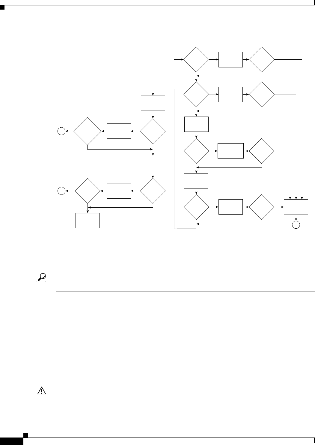
6-2
Cisco uBR7225VXR Universal Broadband Router Hardware Installation Guide
OL-17309-02
Chapter 6 Troubleshooting
Problem Solving with Subsystems
Figure 6-1 Troubleshooting Strategy for Startup Problems
Problem Solving with Subsystems
Tip Isolating a problem to a specific subsystem simplifies the troubleshooting process.
The first step in isolating a problem is to compare what the system is doing to what it should be doing.
Usually a startup problem is caused by a single component, so first isolating the problem to a subsystem
rather than troubleshooting every component in the entire system is more efficient. The
Cisco uBR7225VXR router subsystems are listed below.
•Power subsystem—Includes the power supplies, the external power cable, and the midplane.
•Cooling subsystem—The chassis fan tray is the single component in this subsystem. The fans should
be operating whenever system power is on.
•Processor subsystem—Includes the network processing engine and cable interface line cards.
The system memory and management functions reside on the network processing engine. The enabled
LED on each cable interface line card indicates if the cable interface line card is initialized.
Caution A cable interface line card that is partially installed in the midplane can the cause system to hang and
crash.
Turn on
system power
DC OK
LED on?
No No
Yes Yes
Yes
Yes
Yes
Troubleshoot
power
subsystem
Fans
operating?
Troubleshoot
cooling
subsystem
Check system
state with I/O
controller LEDs
Troubleshoot I/O
controller
and restart
Troubleshoot
port adapters
and restart
System
startup
successful
Obtain
technical
assistance
End
Check system
state with
interface card
LEDs
Interface card
LEDs OK?
Reseat cable
interface
cards and
restart
Check the
headend
setup
Troubleshoot
headend
setup for
RF and data
Digital
data
connections
enabled?
Cable interface
card
LEDs OK?
No Fans
operating?
No
DC OK
LED on?
No No
No No
Yes
I/O
controller
LEDs
OK
I/O
controller
LEDs
OK
Check system
state with port
adapter LEDs
Yes
Yes
Port
adapter
enabled
LEDs
on?
Port
adapter
enabled
LEDs
on?
No
No
Digital
data
connections
enabled?
No
No
End
End
Yes
Yes
62742
Yes

6-3
Cisco uBR7225VXR Universal Broadband Router Hardware Installation Guide
OL-17309-02
Chapter 6 Troubleshooting
Problem Solving with Subsystems
•Cable headend subsystem—External to the Cisco uBR7225VXR router, this subsystem can prevent
operation of the universal broadband router if the headend is not properly set up for the introduction
of digital data into the hybrid fiber-coaxial (HFC) network.
The following section helps you isolate a problem to one of the subsystems and directs you to the
appropriate troubleshooting section.
Identifying Startup Problems
When you start up the Cisco uBR7225VXR router for the first time, observe the startup sequence
described in the “Powering On the Cisco uBR7225VXR Router” section on page 3-18. This section
contains a detailed description of the normal startup sequence.
Although an overtemperature condition is unlikely at initial startup, the environmental monitoring
functions are included in this chapter because they also monitor internal voltages.
Startup problems are commonly caused by source power problems or a board (network processing
engine or cable interface line card) that is not properly connected to the midplane. Always check that
your boards are properly installed in the chassis.
With the exception of the fan tray and network processing engine, LEDs indicate all system states in the
startup sequence. By checking the state of the LEDs, you can determine when and where the system
failed in the startup sequence.
Note On rare occasions, an LED may be faulty.
Use the following descriptions to isolate the problem to a subsystem, then proceed to the appropriate
sections to try to resolve the problem. When you start up the system, by turning on the power supply
switch, the following should occur:
1. You should immediately hear the fans operating. If not, proceed to the “Cooling Subsystem” section
on page 6-4. If you determine that the power supply is functioning normally and that a fan is faulty,
contact a customer service representative. If a fan does not function properly at initial startup, there
are no installation adjustments that you should make.
2. The power supply’s green Input OK LED (at the rear of the chassis) should go on immediately when
you place the power supply switch in the ON (|) position, and should remain on during normal
system operation. If the green Input OK LED does not go on, proceed to the “Power Subsystem”
section on page 6-4.
3. The enabled LED on each cable interface line card comes on when the network processing engine
completes its initialization of the card for operation. The enabled LED indicates that the line card is
receiving power and has been recognized by the network processing engine; it does not indicate the
state of the individual interfaces on the card. If an enabled LED fails to come on, refer to the
“Troubleshooting Cable Interface Line Cards” section on page 6-6.
4. When all LEDs come on to indicate that the system has booted successfully, the initial system
banner should appear on the console screen. If it is not displayed, refer to the “Console and
Auxiliary Port Connection Equipment” section on page 3-14 to verify that the terminal is set
correctly and that it is properly connected to the console port on the NPE.

6-4
Cisco uBR7225VXR Universal Broadband Router Hardware Installation Guide
OL-17309-02
Chapter 6 Troubleshooting
Power Subsystem
Power Subsystem
Check the following to help isolate a problem with the power subsystem:
Step 1 Toggle the power supply switch off and on.
Step 2 On the first power supply, is the Input OK LED on?
a. If yes, the power source is good, and the power supply is functional.
b. If not, make sure that the power cable is connected at both ends. Then toggle the power switch off
and on.
Step 3 If the Input OK LED remains off, and the power switch is on, suspect the power source or the power
cable.
a. Turn the switch off, and connect the power cable to another power source, if available.
b. Turn the switch back on.
c. If the Input OK LED comes on, the problem is the first power source.
Step 4 If the Input OK LED fails to come on after you connect the power supply to a new power source,
a. Turn the power switch off.
b. Replace the power cord.
c. Turn the switch back on.
Step 5 If the Input OK LED comes on, return the first power cable for replacement. Contact a service
representative for further instructions.
Step 6 If the Input OK LED still fails to come on when the power supply is connected to a different power
source with a new power cable, the power supply is probably faulty.
a. If a second power supply is available, and your Cisco uBR7225VXR router has a redundant power
supply bay, install the second power supply in the second bay if there is no power supply installed
in that bay.
b. Contact a service representative for further instructions.
Step 7 Is the Input OK LED on for the second (redundant) power supply?
a. If yes, proceed to the “Cooling Subsystem” section on page 6-4.
b. If not, repeat each of the above procedures for the second power supply.
Step 8 If you are unable to resolve the problem or if you determine that either a power supply or chassis
connector is faulty, contact a service representative for instructions.
Cooling Subsystem
Check the following to help isolate a problem with the cooling system:
Step 1 Verify that the fans are operating when you start up the system.

6-5
Cisco uBR7225VXR Universal Broadband Router Hardware Installation Guide
OL-17309-02
Chapter 6 Troubleshooting
Processor Subsystem
To determine if the fans are operating, listen for them. In noisy environments, place your hand on the
left side of the chassis (when viewing the chassis from the front) to feel for air being forced out the vents.
a. If yes, the power to the fan tray is good.
b. If no, there is a problem with the fan tray or power. See the “Power Subsystem” section on page 6-4.
Step 2 Verify that the following message is not displayed.
Queued messages:
%ENVM-1-SHUTDOWN: Environmental Monitor initiated shutdown
If the message is displayed, the system has detected an overtemperature condition or power
out-of-tolerance condition inside the chassis.
The shutdown message could also indicate a faulty component or temperature sensor. Before the system
shuts down, use the show environment or show environment table command to display the internal
chassis environment.
If an environmental shutdown results from a power out-of-tolerance condition, the power OK LEDs goes
off and the system shuts down. See the “Power Subsystem” section on page 6-4.
Step 3 Although an overtemperature condition is unlikely at initial startup, ensure that heated exhaust air from
other equipment is not entering the inlet vent on the router and that there is sufficient clearance around
the sides of the chassis to allow cooling air to flow. Refer to the “Site Environment” section on page 2-5
and the “Equipment Racks” section on page 2-15 for more on site configurations.
Processor Subsystem
The processor subsystem is comprised of the network processing engine and all cable interface cards.
The network processing engine is a required system component. The system cannot operate unless the
network processing engine is installed properly; however, the system can operate without any
cable interface card installed.
Note The network processing engine (NPE-G1 or NPE-G2) used in Cisco uBR7225VXR allows the router to
work without an I/O controller. NPE-G1 and NPE-G2 works with both Cisco uBR7225 and Cisco
uBR7246 chassis.
If a cable interface card is partially connected to the midplane, the card sends connection incomplete
signals to the processor, which then faults the peripheral component interconnect (PCI) bus and causes
the system to hang.
Therefore, first ensure that the network processing engine is installed properly and the system software
has initialized successfully. Then, if necessary, you can troubleshoot individual cable interface cards.
Troubleshooting the Network Processing Engine
Check the following to help isolate a problem with the network processing engine (NPE):
Step 1 If the NPE enabled LED does not go on as expected:
a. Turn off the power to the router.

6-6
Cisco uBR7225VXR Universal Broadband Router Hardware Installation Guide
OL-17309-02
Chapter 6 Troubleshooting
Processor Subsystem
b. Reseat the network processing engine in its slot.
c. Restart the router.
Step 2 Verify that you are running a version of Cisco IOS software that supports the NPE you are using:
a. For the latest Cisco IOS software release information, refer to the Cisco uBR7200 series release
notes at the following URL:
http://www.cisco.com/en/US/products/hw/cable/ps2217/prod_release_notes_list.html
b. Use the show version command to determine the NPE that is installed in your router.
c. If the router does not respond to the console input, contact Cisco TAC for instructions.
Step 3 If the enabled LED remains off, the system detected a processor hardware failure. This LED should be
on in normal operation. Contact Cisco TAC for instructions.
Troubleshooting Cable Interface Line Cards
Check the following to help isolate a problem with the cable interface line cards:
Step 1 Verify that all cable interface card enabled LEDs are on. If yes, the system is operational.
Step 2 Check to see if all cable interface line card enabled LEDs are off.
a. If yes, verify that you are running a version of Cisco IOS software that supports the cable interface
line cards you are using.
For the latest Cisco IOS software release information, refer to the Cisco uBR7200 series release
notes, at the following URL:
http://www.cisco.com/en/US/products/hw/cable/ps2217/prod_release_notes_list.html
For the latest information on supported features, refer to the Cisco uBR7200 series software feature
guides at the following URL:
http://www.cisco.com/en/US/products/hw/cable/ps2217/products_feature_guides_list.html
b. If the Cisco IOS software is correct, contact Cisco TAC for instructions.
Step 3 Check to see if any cable interface line card enabled LEDs are off.
a. If the enabled LED on an individual cable interface line card is off, check to see if the cable interface
line card has pulled away from the midplane.
b. Reseat the cable interface line card in its slot. (You do not have to turn off the system power when
removing or replacing cable interface line cards.)
c. After the system reinitializes the interfaces, the enabled LED on the cable interface line card should
come on.
Step 4 If the enabled LED remains off, the system detected a processor hardware failure. This LED should be
on in normal operation. Contact Cisco TAC for instructions.

6-7
Cisco uBR7225VXR Universal Broadband Router Hardware Installation Guide
OL-17309-02
Chapter 6 Troubleshooting
Verifying the Downstream Signal
Other Troubleshooting Information Websites
These websites are provided to help you find the most current troubleshooting information:
•Search the Cisco TAC assistance website, at the following URL:
http://www.cisco.com/en/US/support/index.html
•Search cable products field notices at the following URL:
http://www.cisco.com/en/US/support/tsd_products_field_notice_summary.html
•Find router and Cisco IOS architecture technical tips at the following URL:
http://www.cisco.com/en/US/products/hw/routers/ps341/prod_tech_notes_list.html
Verifying the Downstream Signal
If the Cable Modem Termination System (CMTS) has not been properly set up to support digital data,
the Cisco uBR7225VXR router might start up, but fail to support data transmission. You can use a router
with diagnostic capabilities, such as the Cisco uBR900 series cable access routers, to verify the
downstream signal originating from a Cisco uBR7225VXR router. The Cisco uBR900 series cable
access routers are equipped with 64- and 256-QAM receivers that require only minimal setup. Configure
the Cisco uBR900 series routers according to DOCSIS practices.
Tip A maximized signal-to-noise ratio (SNR) estimate optimizes cable interface reliability and service
quality.
Note The SNR estimate for a cable interface installed at the headend should be between 35 and 39 dB.
Before starting this procedure:
•Connect the Cisco uBR7225VXR router to the console. See the “Console and Auxiliary Port
Connection Equipment” section on page 3-14.
•Set up the console. See the Cisco uBR7200 Series Software Configuration Guide at the following
URL:
http://www.cisco.com/en/US/docs/cable/cmts/ubr7200/configuration/guide/cr72scg.html
To verify the downstream signal originating from the Cisco uBR7225VXR router:
Step 1 When the Cisco uBR900 series cable access router is operating and you have established an input signal
of between –10 and +10 dBmV on the modem, enter the show controllers cable-modem 0 command.
This command displays:
•Signal-to-noise ratio (SNR)
•Downstream signal frequency
•Downstream signal modulation scheme (64 QAM or 256 QAM)
Example:
Router# show controllers cable-modem 0
Tuner:status=0x00
Rx:tuner_freq 555000000, symbol_rate 5055926, local_freq 11520000

6-8
Cisco uBR7225VXR Universal Broadband Router Hardware Installation Guide
OL-17309-02
Chapter 6 Troubleshooting
Verifying the Downstream Signal
snr_estimate 352(TenthdB), ber_estimate 0, lock_threshold 26000
QAM in lock, FEC in lock, qam_mode QAM_64
This shows a downstream frequency of 555 MHz, 64-QAM downstream, and an SNR estimate of
35.2 dB.
Note Use the debug cable mac log verbose and show controllers cable 0 mac state commands when
troubleshooting the cable interface’s initialization sequence and locking on the downstream signal.
Step 2 Scan the output for the value corresponding to the “SNR_estimate” variable. If this value is at least
35 dB, then you have an optimized signal. If the value is less than 34 dB, you must adjust the cable
interface line card.
a. Verify that the line card DS output level is correct (+32 dBmV or +42 dBmV).
b. Make sure that the Cisco uBR7225VXR line card IF input to the upconverter is within an acceptable
range (check the upconverter manufacturer’s specifications).
c. Check the upconverter RF output level. A typical setting is +55 to +58 dBmV.
d. Make sure that the upconverter RF output center frequency has been set correctly.
e. Make sure that the proper amount of attenuation has been installed between the upconverter RF
output and the headend combiner input so that the digitally modulated carrier’s average power level
is 6 dB to 10 dB below the level of the analog TV channels.
f. Make sure that the digitally modulated carrier’s RF average power level is in the –15 dBmV to
+15 dBmV range at the input to the cable router.
Note The exact value displayed will vary from cable interface to cable interface; however, the values collected
from measurement to measurement on the same router will be consistent.
Step 3 If the previous steps do not identify the problem, check the downstream digitally modulated carrier using
a QAM analyzer. Several third-party test equipment manufacturers have these instruments available.
a. Measure modulation error ratio (MER), which should be 35 dB or greater in the headend.
b. Check pre- and post-FEC bit error rate (BER). There should be no bit errors in the headend. If bit
errors are observed, one likely cause is sweep transmitter interference.
–
Check the sweep transmitter to make sure that adequate guard bands have been programmed
around the digitally modulated carrier.
–
Bit errors also may be caused by clipping of the digitally modulated carrier in the upconverter
or other active device, including amplifiers and optical transmitters.
c. Evaluate the digitally modulated carrier’s constellation. Look for evidence of:
–
Gain compression
–
Phase noise
–
Inphase and quadrature (I-Q) imbalance
–
Coherent interference
–
Excessive noise
–
Clipping
A-1
Cisco uBR7225VXR Universal Broadband Router Hardware Installation Guide
OL-17309-02
APPENDIX
A
Cisco uBR7225VXR Router Specifications
This appendix provides information on the Cisco uBR7225VXR universal broadband router physical and
system specifications.
Cisco uBR7225VXR Physical and System Specifications
Table A-1 lists the Cisco uBR7225VXR physical specifications, power requirements, and software
compatibility.
Table A-1 Cisco uBR7225VXR Physical Specifications
Description Specification
Midplane Two primary PCI buses and one secondary PCI bus with an aggregate bandwidth of 600 Mbps
Dimensions (H x W x D) 3.5 x 17.32 x 21.875 in. (8.89 x 43.99 x 55.56 cm)
Weight Chassis fully configured with a network processing engine and 2 power supplies: ~ 48 pounds
(21.8 kg)
Heat dissipation 370W1 (1262 Btu2)
Power dissipation 370W (1262 Btu)
AC-input power 300W maximum (for a 300W AC-input with either a single or dual power supply configuration)
540W maximum (for a 540W AC-input with either a single or dual power supply configuration)
Maximum AC-input voltage 100 to 240 VAC3 wide input with power factor correction
AC-input current rating 4A-2A (for a 300W AC-input power supply)
7A-3A (for a 540W AC-input power supply)
AC-input cable 18 AWG4 three-wire cable, with a three-lead IEC-320 receptacle on the power supply end, and
a country-dependent plug on the power source end
Operating Frequency 50/60 Hz
Airflow ~105 cfm5
Temperature 32 to 104°F (0 to 40°C)
Humidity 10 to 90% noncondensing

A-2
Cisco uBR7225VXR Universal Broadband Router Hardware Installation Guide
OL-17309-02
Appendix A Cisco uBR7225VXR Router Specifications
Cisco uBR7225VXR Physical and System Specifications
Cisco IOS Release 12.2(33)SCA and later releases
Agency approval Safety: UL/CSA/IEC/EN 60950-1; AS/NZS60950
EMI: FCC Class A, CSA Class A, EN60555-2, EN55022 Class A, VCCI Class 2,
AS/NRZ 3548 Class A
Immunity: IEC-1000-4-2, IEC-1000-4-3, IEC-1000-4-4, IEC-1000-4-5, IEC-1000-4-6,
IEC-1000-4-11, IEC 1000-3-2
See the Regulatory Compliance and Safety Information for Cisco uBR7200 Series Universal
Broadband Routers at the following URL:
http://www.cisco.com/en/US/docs/cable/cmts/ubr7200/regulatory/compliance/ub72rcsi.html
1. W = watts
2. Btu = British thermal units.
3. VAC = volts alternating current.
4. AWG = American Wire Gauge.
5. cfm = cubic feet per minute.
Table A-1 Cisco uBR7225VXR Physical Specifications (continued)
Description Specification

B-1
Cisco uBR7225VXR Universal Broadband Router Hardware Installation Guide
OL-17309-02
APPENDIX
B
RF Specifications
Information in the following tables is from the DOCSIS and EuroDOCSIS Radio Frequency Interface
Specification, and should be considered minimum recommended performance criteria for reliable data
transmission on cable networks. The full specification may be found at the CableLabs website
(http://www.cablemodem.com), and additional Euro-DOCSIS information may be found at ComLabs
website (http://www.tcomlabs.com).
•NCTA—“NCTA Recommended Practices for Measurements on Cable Television Systems, 2nd
Edition”- National Cable Television Association, Washington DC, revised October 1993
•CableLabs1—“Two-Way Cable Television System Characterization,” Cable Television
Laboratories, Inc., April 12, 1995
•CableLabs2—“Digital Transmission Characterization of Cable Television Systems,” Cable
Television Laboratories, Inc., November, 1999
Note Raw data rate in Table B-1 and Table B-2 includes nominal data throughput plus overhead.
Table B-1 Downstream Channel Data Rates
Modulation Format
Channel
Bandwidth, MHz
Symbol Rate,
Msym/sec
Raw Data Rate,
Mbps
Nominal Data
Rate, Mbps
QAM-64 6 5.056941 30.34 ~27
QAM-256 6 5.360537 42.88 ~38
QAM-64 8 6.952 41.71 ~37
QAM-256 8 6.952 55.62 ~50
Table B-2 Upstream Channel Data Rates
Symbol Rate,
ksym/sec
Channel
Bandwidth,
MHz
QPSK Raw
Data Rate,
Mbps
QPSK Nominal
Data Rate,
Mbps
QAM-16 Raw
Data Rate,
Mbps
QAM-16
Nominal Data
Rate, Mbps
160 0.20 0.32 ~0.3 0.64 ~0.6
320 0.40 0.64 ~0.6 1.28 ~1.2
640 0.80 1.28 ~1.2 2.56 ~2.3

B-2
Cisco uBR7225VXR Universal Broadband Router Hardware Installation Guide
OL-17309-02
Appendix B RF Specifications
DOCSIS 1.0 Transmission Characteristics
DOCSIS 1.0 Transmission Characteristics
The following tables provide information on the assumed downstream RF channel transmission
characteristics for DOCSIS 1.0.
Downstream RF Channel Transmission Characteristics
Transmission is from the headend combiner to the cable modem input at the customer location.
Measurement methods are defined in NCTA or CableLabs2 documentation.
Go to the following URL: http://www.ncta.com/. Search on “transmission”.
Go to the following URL: http://www.cablelabs.com/.
1280 1.60 2.56 ~2.3 5.12 ~4.6
2560 3.20 5.12 ~4.6 10.24 ~9.0
Table B-2 Upstream Channel Data Rates (continued)
Symbol Rate,
ksym/sec
Channel
Bandwidth,
MHz
QPSK Raw
Data Rate,
Mbps
QPSK Nominal
Data Rate,
Mbps
QAM-16 Raw
Data Rate,
Mbps
QAM-16
Nominal Data
Rate, Mbps
Table B-3 DOCSIS 1.0 Assumed Downstream RF Channel Transmission Characteristics
Parameter Value
Frequency range1Cable system normal downstream operating range is from 50
MHz to as high as 860 MHz. However, the values in this table
apply only at frequencies ≥ 88 MHz.
RF channel spacing (design bandwidth) 6 MHz
Transit delay from headend to most distant customer ≤ 0.800 msec (typically much less)
Carrier-to-noise ratio in a 6-MHz band (analog video level) Not less than 35 dB2
Carrier-to-interference ratio for total power (discrete and
broadband ingress signals)
Not less than 35 dB within the design bandwidth
Composite triple beat distortion for analog modulated carriers Not greater than –50 dBc3 within the design bandwidth
Composite second-order distortion for analog modulated
carriers
Not greater than –50 dBc within the design bandwidth
Cross-modulation level Not greater than –40 dBc within the design bandwidth
Amplitude ripple 0.5 dB within the design bandwidth
Group delay ripple in the spectrum occupied by the CMTS 75 ns within the design bandwidth
Micro-reflections bound for dominant echo –10 dBc @ ≤ 0.5 microseconds
–15 dBc @ ≤ 1.0 microseconds
–20 dBc @ ≤ 1.5 microseconds
–30 dBc @ >1.5 microseconds
Carrier hum modulation4Not greater than –26 dBc (5%)
Burst noise Not longer than 25 μsec at a 10-Hz average rate
Signal level slope, 50-750 MHz 16 dB

B-3
Cisco uBR7225VXR Universal Broadband Router Hardware Installation Guide
OL-17309-02
Appendix B RF Specifications
DOCSIS 1.0 Transmission Characteristics
Upstream RF Channel Transmission Characteristics
Transmission is from the cable modem output at the customer location to the headend. Measurement
methods are defined in NCTA or CableLabs2 documentation.
Seasonal and diurnal signal level variation 8 dB
Maximum analog video carrier level at the cable modem
input, inclusive of above signal level variation
17 dBmV
Lowest analog video carrier level at the cable modem input,
inclusive of above signal level variation
–5 dBmV
1. For measurements above the normal operating frequency band (except hum), impairments are referenced to the highest-frequency NTSC carrier level.
2. This presumes that the digital carrier is operated at analog peak carrier level. When the digital carrier is operated below the analog peak carrier level, the
carrier-to-noise ratio may be less.
3. Decibels relative to carrier, a common measurement in RF engineering to specify the power of a sideband in a modulated signal relative to the carrier in
decibels.
4. For hum measurements above the normal downstream operating frequency band, a continuous-wave carrier is sent at the test frequency at the same level
as the highest-frequency NTSC carrier.
Table B-3 DOCSIS 1.0 Assumed Downstream RF Channel Transmission Characteristics (continued)
Parameter Value
Table B-4 DOCSIS 1.0 Assumed Upstream RF Channel Transmission Characteristics
Parameter Value
Frequency range 5 to 42 MHz edge to edge
Transit delay from the most distant cable modem to the
nearest cable modem or CMTS
≤ 0.800 msec (typically much less)
Carrier-to-noise ratio Not less than 25 dB
Carrier-to-ingress power (the sum of discrete and broadband
ingress signals) ratio
Not less than 25 dB1
1. Ingress avoidance or tolerance techniques may be used to ensure operation in the presence of time varying discrete ingress signals that could be as high
as 0 dBc. (CableLabs1)
Carrier-to-interference (the sum of noise, distortion,
common-path distortion, and cross-modulation) ratio
Not less than 25 dB
Carrier hum modulation Not greater than –23 dBc (7%)
Burst noise Not longer than 10 μsec at a 1-kHz average rate for most
cases2, 3
2. Amplitude and frequency characteristics sufficiently strong to partially or wholly mask the data carrier.
3. Impulse noise levels more prevalent at lower frequencies (<15 MHz).
Amplitude ripple 5 to 42 MHz: 0.5 dB/MHz
Group delay ripple 5 to 42 MHz: 200 ns/MHz
Micro-reflections—single echo –10 dBc @ ≤ 0.5 microseconds
–20 dBc @ ≤ 1.0 microseconds
–30 dBc @ > 1.0 microseconds
Seasonal and diurnal signal level variation Not greater than 8 dB min to max

B-4
Cisco uBR7225VXR Universal Broadband Router Hardware Installation Guide
OL-17309-02
Appendix B RF Specifications
DOCSIS 1.1 Transmission Characteristics
DOCSIS 1.1 Transmission Characteristics
The following tables provide information on the assumed downstream RF channel transmission
characteristics for DOCSIS 1.1.
Downstream RF Channel Transmission Characteristics
Transmission is from the headend combiner to the cable modem input at the customer location.
Measurement methods are defined in NCTA or CableLabs2 documentation.
Go to the following URL: http://www.ncta.com/. Search on “transmission”.
Go to the following URL: http://www.cablelabs.com/.
Table B-5 DOCSIS 1.1 Assumed Downstream RF Channel Transmission Characteristics
Parameter Value
Frequency range Cable system normal downstream operating range is from
50 MHz to as high as 860 MHz. However, the values in this
table apply only at frequencies ≥ 88 MHz.
RF channel spacing (design bandwidth) 6 MHz
Transit delay from headend to most distant customer ≤ 0.800 msec (typically much less)
Carrier-to-noise ratio in a 6-MHz band Not less than 35 dB1
1. Measured relative to a QAM signal that is equal to the nominal video level in the plant.
Carrier-to-composite triple beat distortion ratio Not less than 41 dB1
Carrier-to-composite second order distortion ratio Not less than 41 dB1
Carrier-to-cross-modulation ratio Not less than 41 dB1
Carrier-to-any other discrete interference (ingress) Not less than 41 dB1
Amplitude ripple 3 dB within the design bandwidth
Group delay ripple in the spectrum occupied by the CMTS 75 ns within the design bandwidth
Micro-reflections bound for dominant echo –10 dBc @ ≤ 0.5 microseconds
–15 dBc @ ≤ 1.0 microseconds
–20 dBc @ ≤ 1.5 microseconds
–30 dBc @ >1.5 microseconds
Carrier hum modulation Not greater than –26 dBc (5%)
Burst noise Not longer than 25 microseconds at a 10-Hz average rate
Maximum analog video carrier level at the cable modem input 17 dBmV
Maximum number of analog carriers 121

B-5
Cisco uBR7225VXR Universal Broadband Router Hardware Installation Guide
OL-17309-02
Appendix B RF Specifications
EuroDOCSIS Transmission Characteristics
Upstream RF Channel Transmission Characteristics
Transmission is from the cable modem output at the customer location to the headend. Measurement
methods are defined in NCTA or CableLabs2 documentation.
EuroDOCSIS Transmission Characteristics
The following tables provide information on the assumed RF channel transmission characteristics for
EuroDOCSIS.
Table B-6 DOCSIS 1.1 Assumed Upstream RF Channel Transmission Characteristics
Parameter Value
Frequency range 5 to 42 MHz edge to edge
Transit delay from the most distant cable modem to the
nearest cable modem or CMTS
≤ 0.800 msec (typically much less)
Carrier-to-interference plus ingress (the sum of noise,
distortion, common-path distortion, and cross-modulation
and the sum of discrete and broadband ingress signals,
impulse noise excluded) ratio
Not less than 25 dB1
1. Ingress avoidance or tolerance techniques may be used to ensure operation in the presence of time varying discrete ingress signals that could be as high
as 10 dBc. Ratios are guaranteed only within the digital carrier channels.
Carrier hum modulation Not greater than –23 dBc (7%)
Burst noise Not longer than 10 microseconds at a 1-kHz average rate for
most cases2, 3
2. Amplitude and frequency characteristics sufficiently strong to partially or wholly mask the data carrier.
3. Impulse noise levels more prevalent at lower frequencies (<15 MHz).
Amplitude ripple 5 to 42 MHz: 0.5 dB/MHz
Group delay ripple 5 to 42 MHz: 200 ns/MHz
Micro-reflections—single echo –10 dBc @ ≤ 0.5 microseconds
–20 dBc @ ≤ 1.0 microseconds
–30 dBc @ > 1.0 microseconds
Seasonal and diurnal reverse gain (loss) variation Not greater than 14 dB min to max

B-6
Cisco uBR7225VXR Universal Broadband Router Hardware Installation Guide
OL-17309-02
Appendix B RF Specifications
EuroDOCSIS Transmission Characteristics
Downstream RF Channel Transmission Characteristics
Transmission is from the headend combiner to the cable modem input at the customer location.
Measurement methods are defined in CENELEC 50083-7 documentation.
Table B-7 EuroDOCSIS Assumed Downstream RF Channel Transmission Characteristics for Analog TV and Sound
Signals
Parameter Value
Frequency range1
1. For measurements shown, the normal downstream operating frequency band (except hum), impairments are referenced to the highest-frequency
PAL/SECAM carrier level.
Cable system normal downstream operating range is from
47 MHz to as high as 862 MHz. However, the operating range
for data communication is from 108 to 862 MHz. The use of
frequencies between 108 and 136 MHz may be forbidden due
to national regulation with regard to interference with
aeronautical navigation frequencies.
RF channel spacing (design bandwidth) 7/8 MHz, 8 MHz channels are used for data communication
Transit delay from headend to most distant customer ≤ 0.800 msec (typically much less)
Carrier-to-noise ratio in a 8-MHz band (analog video level) Not less than 44 dB2
2. This presumes that the digital carrier is operated at analog peak carrier level. When the digital carrier is operated below the analog peak carrier level, the
carrier-to-noise ratio may be less.
Carrier-to-interference ratio for total power (discrete and
broadband ingress signals)
Not less than 52 dB within the design bandwidth
Composite triple beat distortion for analog modulated carriers PAL—Not greater than –57 dBc within the design bandwidth
SECAM—Not greater than –52 dBc within the design
bandwidth.
Composite second order distortion for analog modulated
carriers
PAL—Not greater than –57 dBc within the design bandwidth.
SECAM—Not greater than –52 dBc within the design
bandwidth.
Cross-modulation level Under consideration
Amplitude ripple 2.5 dB in 8 MHz
Group delay ripple in the spectrum occupied by the CMTS 100 ns over frequency range 0.5 to 4.43 MHz
Micro-reflections bound for dominant echo –10 dBc @ ≤ 0.5 microseconds
–15 dBc @ ≤ 1.0 microseconds
–20 dBc @ ≤ 1.5 microseconds
–30 dBc @ > 1.5 microseconds
Carrier hum modulation3Not greater than –46 dBc (5%)
Burst noise Not longer than 25 microseconds at a 10-Hz average rate
Signal level slope, 85–862 MHz 12 dB
Seasonal and diurnal signal level variation 8 dB
Maximum analog video carrier level at the system outlet,
inclusive of above signal level variation
PAL: 77 dBmicroV
SECAM: 74 dBmicroV
Lowest analog video carrier level at the system outlet,
inclusive of above signal level variation
PAL: 60 dBmicroV
SECAM: 57 dBmicroV

B-7
Cisco uBR7225VXR Universal Broadband Router Hardware Installation Guide
OL-17309-02
Appendix B RF Specifications
EuroDOCSIS Transmission Characteristics
Upstream RF Channel Transmission Characteristics
Transmission is from the cable modem output at the customer location to the headend.
3. For hum measurements above the normal downstream operating frequency band, a continuous-wave carrier is sent to the test frequency at the same level
as the highest-frequency PAL/SECAM carrier.
Table B-8 EuroDOCSIS Assumed Upstream RF Channel Transmission Characteristics
Parameter Value
Frequency range 5 up to 65 MHz to edge
Transit delay from the most distant cable modem to the
nearest cable modem or cable modem termination system
≤ 0.800 msec (typically much less)
Carrier-to-noise ratio in active channel Not less than 22 dB
Carrier-to-ingress power (the sum of discrete and broadband
ingress signals) ratio in active channel
Not less than 22 dB1
1. Ingress avoidance or tolerance techniques may be used to ensure operation in the presence of time varying discrete ingress signals that could be as high
as 0 dBc.
Carrier-to-interference (the sum of noise, distortion,
common-path distortion, and cross-modulation) ratio in
active channel
Not less than 22 dB
Carrier hum modulation Not greater than –23 dBc (7%)
Burst noise Not longer than 10 microseconds at a 1 kHz average rate for
most cases2, 3
2. Amplitude and frequency characteristics sufficiently strong to partially or wholly mask the data carrier.
3. Impulse noise levels more prevalent at lower frequencies (<15 MHz).
Amplitude ripple 5 to 65 MHz: 2.5 dB in 2 MHz
Group delay ripple 5 to 65 MHz: 300 ns in 2 MHz
Micro-reflections—single echo –10 dBc @ ≤ 0.5 microseconds
–20 dBc @ ≤ 1.0 microseconds
–30 dBc @ > 1.0 microseconds
Seasonal and diurnal signal level variation Not greater than 12 dB min to max

B-8
Cisco uBR7225VXR Universal Broadband Router Hardware Installation Guide
OL-17309-02
Appendix B RF Specifications
Electrical Input and Output
Electrical Input and Output
The information in Table B-9 and Table B-10 relates to both DOCSIS and EuroDOCSIS specifications.
Table B-9 Electrical Input to the Cable Modem
Parameter Value
Center frequency •DOCSIS: 91 to 857 MHz ±30 kHz
•EuroDOCSIS: 112 to 858 MHz ±30 kHz
Level range (one channel) •DOCSIS: –15 dBmV to +15 dBmV
•EuroDOCSIS: 43 to 73 dBmicroV for QAM-64
47 to 77 dBmicroV for QAM-256
Modulation type QAM-64 and QAM-256
Symbol rate (nominal) •DOCSIS: 5.056941 Msym/sec (QAM-64) and 5.360537
Msym/sec (QAM-256)
•EuroDOCSIS: 6.952 Msym/sec for QAM-64 and
QAM-256
Bandwidth •DOCSIS: 6 MHz
–
18% square root raised cosine shaping for QAM-64
–
12% square root raised cosine shaping for QAM-256
•EuroDOCSIS: 8 MHz
–
15% square root raised cosine shaping for both
QAM-64 and QAM-256
Total input power (40–900 MHz) < 30 dBmV (90 dBmicroV)
Input (load) impedance 75 ohms
Input return loss •DOCSIS: > 6 dB (88–860 MHz)
•EuroDOCSIS: > 6 dB (85–862 MHz)
Connector F connector per ISO-169-24 (common with the output)
Table B-10 Upstream Electrical Output from the Cable Modem
Parameter Value
Frequency •DOCSIS: 5 to 42 MHz edge to edge
•EuroDOCSIS: 5 to 65 MHz edge to edge
Level range (one channel) •QAM-16: +8 to +55 dBmV (+68 to +115 dBmicroV)
•QPSK: +8 to +58 dBmV (+68 to +118 dBmicroV)
Modulation type QPSK and QAM-16
Symbol rate (nominal) 160 ksym/sec
320 ksym/sec
640 ksym/sec
1280 ksym/sec
2560 ksym/sec

B-9
Cisco uBR7225VXR Universal Broadband Router Hardware Installation Guide
OL-17309-02
Appendix B RF Specifications
Electrical Input and Output
Bandwidth 200 kHz
400 kHz
800 kHz
1600 kHz
3200 kHz
Output impedance 75 ohms
Output return loss •DOCSIS: >6 dB (5–42 MHz)
•EuroDOCSIS: >6 dB (5–65 MHz)
Connector F connector per ISO-169-24 (common with the input)
Table B-10 Upstream Electrical Output from the Cable Modem (continued)
Parameter Value

B-10
Cisco uBR7225VXR Universal Broadband Router Hardware Installation Guide
OL-17309-02
Appendix B RF Specifications
Electrical Input and Output

C-1
Cisco uBR7225VXR Universal Broadband Router Hardware Installation Guide
OL-17309-02
APPENDIX
C
Cable Specifications
This appendix contains cable and cable pinout information for the Cisco uBR7225VXR universal
broadband router.
•Coaxial Cables, page C-1
•Console and Auxiliary Port Cables and Pinouts, page C-2
•Fast Ethernet Port Cables and Pinouts, page C-4
•Fiber-Optic Cables and Connectors, page C-6
Note This appendix specifies pinouts only for the pins used. Pins not listed in the tables are not connected.
Coaxial Cables
The coaxial cable used to connect the Cisco uBR7200 series universal broadband routers at the headend
should be very high-quality cable.
We recommend that you use a headend-grade coaxial cable or a quad-shield coaxial cable to connect the
cable interface line cards to the hybrid fiber-coaxial (HFC) network. The center conductor must be
straight and extend 1/8 inch (3.2 mm) beyond the end of the connector, and the connector should be
securely crimped to the cable. The following headend cables are recommended:
•59-series cable (preferred)—20 AWG (0.032 inch/0.81 mm diameter) silver plated, copper-clad,
steel center conductor; bonded foil inner shield; 95 percent braid second shield; nonbonded foil third
shield; 95 percent braid fourth shield.
•59-series quad shield—20 AWG (0.032 inch/0.81 mm diameter) copper-clad steel center conductor;
bonded foil inner shield; 53 percent braid second shield; nonbonded foil third shield; 34–35 percent
braid fourth shield.
•6-series quad shield—18 AWG (0.0359 inch/0.91 mm diameter) copper-clad steel center conductor;
bonded foil inner shield; 60 percent braid second shield; nonbonded foil third shield; 40–42 percent
braid fourth shield.
Note Any of the three of the coaxial cables listed can be used to connect a Cisco cable interface line card to
the HFC network; however, the consistent use of 59-series cable is preferred. If you connect a 59-series
cable to a cable interface line card that was previously connected using 6-series cable, the difference in
the center connector diameter might cause intermittent connectivity loss.
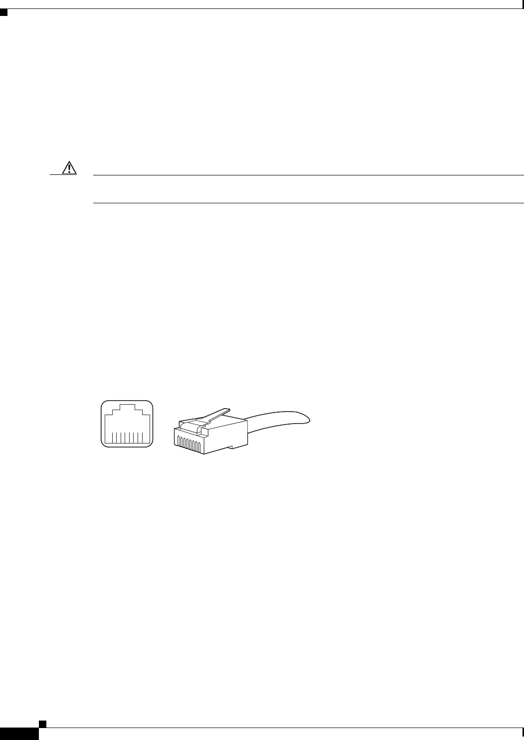
C-2
Cisco uBR7225VXR Universal Broadband Router Hardware Installation Guide
OL-17309-02
Appendix C Cable Specifications
Console and Auxiliary Port Cables and Pinouts
If you use different types of coaxial cable, the following problems can appear:
•Damage to Cisco uBR7225VXR cable interface line card connectors—Cable interface line card
connectors are designed for 59-series or 6-series cable and connectors. Larger cables can damage
the connectors.
•Poor return loss—High-quality cable and correct connectors help to ensure an optimal return loss of
16 dB or more.
Caution Poorly shielded coaxial cable may result in undesired signal leakage (egress), interference from
over-the-air signals (ingress), or crosstalk between cables in close physical proximity.
Console and Auxiliary Port Cables and Pinouts
The router arrives with a console and auxiliary cable kit, which contains the cable and adapters you need
to connect a console (an ASCII terminal or PC running terminal emulation software) or modem to the
router. The console and auxiliary cable kit includes:
•RJ-45-to-RJ-45 rollover cable
•RJ-45-to-DB-9 female data terminal equipment (DTE) adapter labeled TERMINAL
•RJ-45-to-DB-25 male data communications equipment (DCE) adapter labeled MODEM
Figure C-1 shows the RJ-45 cable connector.
Figure C-1 RJ-45 Plug and Receptacle
Identifying an RJ-45 Rollover Cable
You can identify a rollover cable by holding the two ends of the cable next to each other with the tab at
the back. The wire connected to the pin on the outside of the left hand plug should be the same color as
the wire connected to the pin on the outside of the right hand plug, as shown in Figure C-2.
242232
8 7 6 5 4 3 2 1
RJ-45 connector
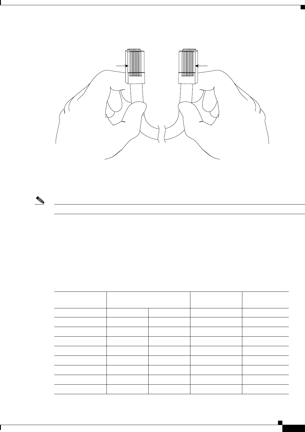
C-3
Cisco uBR7225VXR Universal Broadband Router Hardware Installation Guide
OL-17309-02
Appendix C Cable Specifications
Console and Auxiliary Port Cables and Pinouts
Figure C-2 RJ-45 Rollover Cable Identification
The colored wires at one connector are in the reverse order at the other connector (reverses pins 1 and 8,
2 and 7, 3 and 6, 4 and 5, 5 and 4, 6 and 3, 7 and 2, 8 and 1).
The wires of the straight-through cable are in the same sequence at both ends of the cable.
Note If your cable was purchased from Cisco, pin 8 is white.
Console Port Cables and Pinouts
Use the RJ-45-to-RJ-45 rollover cable and RJ-45-to-DB-9 female DTE adapter (labeled TERMINAL) to
connect the console port to a PC running terminal emulation software. Table C-1 lists the signals and
pinouts for the asynchronous serial console port, the RJ-45-to-RJ-45 rollover cable, and the
RJ-45-to-DB-9 female DTE adapter.
Pin 1 Pin 8
H3824
Pin 1 and pin 8
should be the
same color
Table C-1 Console Port Signaling and Cabling Using a DB-9 Adapter
Console Port (DTE) RJ-45-to-RJ-45 Rollover Cable
RJ-45-to-DB-9
Terminal Adapter Console Device
Signal RJ-45 Pin RJ-45 Pin DB-9 Pin Signal
RTS 11
1. Pin 1 is connected internally to pin 8.
88 CTS
DTR 276 DSR
TxD 362 RxD
GND455 GND
GND545 GND
RxD 633 TxD
DSR 724 DTR
CTS 8117 RTS

C-4
Cisco uBR7225VXR Universal Broadband Router Hardware Installation Guide
OL-17309-02
Appendix C Cable Specifications
Fast Ethernet Port Cables and Pinouts
Auxiliary Port Cables and Pinouts
Use the RJ-45-to-RJ-45 rollover cable and RJ-45-to-DB-25 male DCE adapter (labeled MODEM) to
connect the auxiliary port to a modem. Table C-2 lists the signals and pinouts for the asynchronous serial
auxiliary port, the RJ-45-to-RJ-45 rollover cable, and the RJ-45-to-DB-25 male DCE adapter (labeled
MODEM).
Fast Ethernet Port Cables and Pinouts
The 10Base-T/100Base-TX Fast Ethernet ports support IEEE 802.3 and IEEE 802.3u specifications for
10-Mbps and 100-Mbps transmission over unshielded twisted-pair (UTP) cables. Each Fast Ethernet port
on the NPE has an RJ-45 connector to attach to Category 3 or Category 5 UTP cables.
•Use a Category 3 UTP crossover cable when connecting 10Base-T port to a hub.
•Use a Category 3 UTP straight-through cable when connecting to a PC or other Ethernet device.
•Use a Category 5 UTP crossover cable when connecting 100Base-TX to a hub.
•Use a Category 5 UTP straight-through cable when connecting to a PC or other Ethernet device.
Note Cisco does not supply Category 3 or Category 5 UTP RJ-45 cables; these cables are available
commercially.
Identifying an RJ-45 Crossover Cable
You can identify a crossover cable by comparing the two modular ends of the cable. Hold the cables
side-by-side with the tab at the back. The first (far left) colored wire (pin 1) at one end of the cable is
the third colored wire (pin 3) at the other end of the cable. The second colored wire (pin 2) at one end
of the cable is the sixth colored wire (pin 6) at the other end of the cable. Pin 1 wire is white. See
Figure C-3.
Table C-2 Auxiliary Port Signaling and Cabling Using a DB-25 Adapter
AUX Port (DTE) RJ-45-to-RJ-45 Rollover Cable
RJ-45-to-DB-25
Modem Adapter Modem (DCE)
Signal RJ-45 Pin RJ-45 Pin DB-25 Pin Signal
RTS 1 8 4 RTS
DTR 2720 DTR
TxD 363 TxD
GND 4 5 7 GND
GND 5 4 7 GND
RxD 6 3 2 RxD
DSR 7 2 8 DCD
CTS 8 1 5 CTS
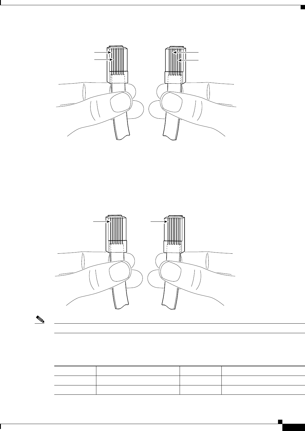
C-5
Cisco uBR7225VXR Universal Broadband Router Hardware Installation Guide
OL-17309-02
Appendix C Cable Specifications
Fast Ethernet Port Cables and Pinouts
Figure C-3 RJ-45 Crossover Cable Identification
Identifying an RJ-45 Straight-Through Cable
You can identify a straight-through cable by comparing the two modular ends of the cable. Hold the
cables side-by-side with the tab at the back. The straight-through cable’s wires are in the same sequence
at both ends of the cable. See Figure C-4.
Figure C-4 RJ-45 Straight-Through Cable Identification
Note If your cable was purchased from Cisco, pin 1 is white. Pins 4, 5, 7, and 8 are not connected.
Table C-3 lists the pinouts for the two Fast Ethernet ports.
62741
Pin 1
Pin 2
Pin 3
Pin 6
62740
Pin 1 Pin 1
Table C-3 10BASE-T RJ-45 Connector Pinouts
RJ-45 Pin Description RJ-45 Pin Description
1Tx+ 3Rx+
2Tx– 6Rx–
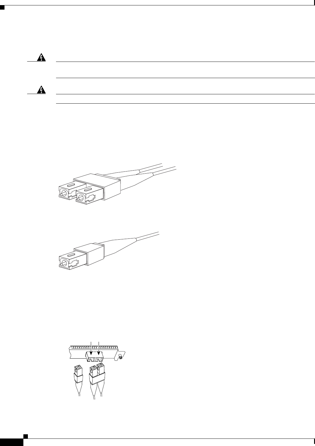
C-6
Cisco uBR7225VXR Universal Broadband Router Hardware Installation Guide
OL-17309-02
Appendix C Cable Specifications
Fiber-Optic Cables and Connectors
Fiber-Optic Cables and Connectors
Warning
Because invisible radiation may be emitted from the aperture of the port when no fiber cable is
connected, avoid exposure to radiation and do not stare into open apertures.
Statement 1056
Warning
Class 1 laser product.
Statement 1008
Use a single-mode or multimode fiber-optic interface cable to connect your Cisco uBR7225VXR router
to another router or switch. In general, multimode cables are gray or orange, and single-mode cables are
yellow. For Ethernet and multimode fiber-optic connections, use one duplex SC-type connector
(Figure C-5) or two simplex SC-type connectors. (See Figure C-6.)
Figure C-5 Duplex SC Cable Connector
Figure C-6 Simplex SC Cable Connector
Attach either one duplex fiber cable or two simplex fiber cables between the digital pulse terminator
(DPT) port adapter and the device to which the DPT port adapter is connected. Observe the receive (RX)
and transmit (TX) cable relationship shown in Figure C-7.
Figure C-7 Attaching Simplex or Duplex Fiber-Optic Cables
242230
242231
25168
SONET/SDH with simplex
or duplex SC connectors
To network
Simplex
RX TX
Duplex

D-1
Cisco uBR7225VXR Universal Broadband Router Hardware Installation Guide
OL-17309-02
APPENDIX
D
Industry-Standard Wiring Plans
About Wiring Standards
In a traditional cable headend, a large number of wires connect the various components of the headend
system. To organize the many wires, some cable operators use color-coding on the wire jackets based on
signal type, and channel number or program content.
With the advancement of two-way Data-over-Cable services and fiber-optic nodes on the network, the
cable headend wiring has become even more complex:
•A single upstream cable can now carry signals from multiple services and from many combinations
of fiber-optic nodes—not just one.
•Each fiber-optic node has different content provided by the digital data services at the same
frequency or channel locations—not separate channels.
•For proper testing of the network, more downstream test points are required. In addition, upstream
test points of calibrated signal amplitude are becoming essential.
Note Several third-party companies have available commercially-manufactured equipment that includes fixed
or modular splitters, combiners, and test points for headend RF management.
Many coaxial cable manufacturers offer various jacket color options for headend-grade coaxial cable. To
date, there are no official standards for headend coaxial cable color schemes, although individual cable
companies and multiple system operators (MSOs) have in some instances implemented their own.
The telephone industry has developed standardized color schemes for telephony wiring applications.
Some of these are included here for the benefit of cable operators that have or are deploying voice
services on their cable networks. This appendix also includes standardized color codes for optical fiber.

D-2
Cisco uBR7225VXR Universal Broadband Router Hardware Installation Guide
OL-17309-02
Appendix D Industry-Standard Wiring Plans
Optical Fiber Color Codes
TIA/EIA Standards Information
A number of Electronic Industries Alliance (EIA) and Telecommunications Industry Association (TIA)
standards are applicable to wiring.
Following is a list of applicable standards:
•TIA/EIA Telecommunications Building Wiring Standards Collection
•TIA/EIA-568A—Commercial Building Telecommunications Cabling Standard
•TIA/EIA-569A—Commercial Building Standard for Telecommunications Pathways and Spaces
•TIA/EIA-570A—Residential Telecommunications Cabling Standard
•TIA/EIA-598—Optical Fiber Cable Color Coding
•TIA/EIA-606—The Administration Standard for the Telecommunications Infrastructure of
Commercial Buildings
•TIA/EIA-607—Commercial Building Grounding and Bonding Requirements for
Telecommunications
•TIA/EIA TSB 72—Centralized Optical Fiber Cabling Guidelines
•TIA/EIA TSB 75—Additional Horizontal Cabling Practices for Open Offices
•TIA/EIA TSB 95—Additional Performance Guidelines for 4-Pair 100 OHM Category 5 Cabling
In addition, the following relevant standards are available from Global Engineering Documents:
•FIBS PUB 175—Federal Building Standard for Telecommunication Pathways and Spaces
•FIBS PUB 176—Residential and Light Commercial Telecommunications Wiring Standard
Optical Fiber Color Codes
The most common color code for optical fiber is based on the ten colors that are used for plastic insulated
conductor copper cables. Two other colors have been added to bring the optical fiber color code to
twelve. These colors are now standardized under TIE/EIA-598—Optical Fiber Cable Color Coding.
The coloring specified in TIA/EIA–598 is used to identify individual optical fibers when the colors are
applied to the surface of the coated fiber or included directly in the fiber’s secondary coating. See
Table D-1. Buffered fibers have colored plastic buffering jackets. The standard colors also may be used
to identify units (groups of fibers or loose tubes) or ribbons on a given cable. As well, units and ribbons
may be identified with printed markings.
Table D-1 TIA/EIA–598 Color Code
Position Color
1Blue
2Orange
3 Green
4Brown
5 Slate
6 White
7Red

D-3
Cisco uBR7225VXR Universal Broadband Router Hardware Installation Guide
OL-17309-02
Appendix D Industry-Standard Wiring Plans
Telephone Wire Color Codes
Telephone Wire Color Codes
To help simplify wire management, AT&T has devised a uniform scheme for dealing with large numbers
of wires for the telephone industry. The scheme uses two color codes—one for large numbers of wires
organized in pairs—and the other for smaller numbers of wires that can also be organized in pairs. We
recommend that you try to implement this wiring scheme whenever possible.
For large numbers of wires, each pair is assigned a two-color code. The colors are selected from two
groups of five, resulting in what is called a binder-group of 25 pairs. The colors used for a group are
white, red, black, yellow, and violet. The colors used for “pair within a group” are blue, orange, green,
brown, and slate.
Each pair must have a unique color combination. One wire within each pair has a solid background of
its group color and stripes of the “pair within a group” color; the second wire has the colors reversed.
Table D-2 lists the sequences. Note that red-brown and red-orange wires may be easily confused.
8Black
9 Yellow
10 Violet
11 Rose
12 Aqua
Table D-1 TIA/EIA–598 Color Code (continued)
Position Color
Table D-2 Telephone Industry 25-Pair Color Code and Pin Numbers
Pair Number Wire Number Solid Color Stripe Color Pin Number
1 1 White Blue 26
12BlueWhite1
2 1 White Orange 27
2 2 Orange White 2
3 1 White Green 28
32GreenWhite3
41WhiteBrown29
42BrownWhite4
51WhiteSlate30
5 2 Slate White 5
6 1 Red Blue 31
62BlueRed6
7 1 Red Orange 32
72OrangeRed7
8 1 Red Green 33
82GreenRed8

D-4
Cisco uBR7225VXR Universal Broadband Router Hardware Installation Guide
OL-17309-02
Appendix D Industry-Standard Wiring Plans
Telephone Wire Color Codes
Cables with more than 25 pairs of wires are constructed from 25-pair groups. Very large cables have
other variations generally not encountered inside terminal wire plants.
91RedBrown34
92BrownRed9
10 1 Red Slate 35
10 2 Slate Red 10
11 1 Black Blue 36
11 2 Blue Black 11
12 1 Black Orange 37
12 2 Orange Black 12
13 1 Black Green 38
13 2 Green Black 13
14 1 Black Brown 39
14 2 Brown Black 14
15 1 Black Slate 40
15 2 Slate Black 15
16 1 Yellow Blue 41
16 2 Blue Yellow 16
17 1 Yellow Orange 42
17 2 Orange Yellow 17
18 1 Yellow Green 43
18 2 Green Yellow 18
19 1 Yellow Brown 44
19 2 Brown Yellow 19
20 1 Yellow Slate 45
20 2 Slate Yellow 20
21 1 Violet Blue 46
21 2 Blue Violet 21
22 1 Violet Orange 47
22 2 Orange Violet 22
23 1 Violet Green 48
23 2 Green Violet 23
24 1 Violet Brown 49
24 2 Brown Violet 24
25 1 Violet Slate 50
25 2 Slate Violet 25
Table D-2 Telephone Industry 25-Pair Color Code and Pin Numbers (continued)
Pair Number Wire Number Solid Color Stripe Color Pin Number

D-5
Cisco uBR7225VXR Universal Broadband Router Hardware Installation Guide
OL-17309-02
Appendix D Industry-Standard Wiring Plans
Telephone Wire Color Codes
For small wiring groups, such as wires for an individual telephone station or terminal, you may use a
second color-code scheme. Table D-2 lists this color code and the usual correspondence with the
paired-wire color code. The alternate color code is included, because sometimes the station wire uses
the first three pairs of the standard color code (white-blue, blue-white, and so on), while other times it
uses the six alternate color wires.
Table D-3 Alternate Color Code Scheme for Smaller Numbers of Wires
Pair Number Wire Number Solid Color Stripe Color Alternate Color Pin Number
11WhiteBlueGreen4
12BlueWhiteRed3
21WhiteOrangeBlack2
2 2 Orange White Yellow 5
31WhiteGreenWhite1
3 2 Green White Blue 6

D-6
Cisco uBR7225VXR Universal Broadband Router Hardware Installation Guide
OL-17309-02
Appendix D Industry-Standard Wiring Plans
Telephone Wire Color Codes

E-1
Cisco uBR7225VXR Universal Broadband Router Hardware Installation Guide
OL-17309-02
APPENDIX
E
Frequency Allocation Tables
This appendix provides information on broadcast and cable television NTSC and PAL/SECAM
standards and frequencies used around the world.
There are three standards for transmitting video. They are defined by the method of encoding color onto
a monochrome signal. The methods are defined as:
•NTSC—National Television System Committee
NTSC is the current standard used for analog television in the United States and elsewhere. NTSC
supports color television transmission in a 6-MHz channel bandwidth and has 525 interlaced scan
lines. Two fields are interlaced to make one frame with a frame rate of 29.97 frames per second and
a field rate of 59.94 fields per second. A fraction (approximately 8 percent) of the available
bandwidth is used for signal synchronization between the transmitter and the receiver, giving an
effective resolution of 640 x 480. The aspect ratio, or ratio of picture width to picture height, is 4:3.
•PAL—Phase Alternating Line
PAL is a composite color system similar to NTSC. In PAL, however, the color difference signals
alternate phase at the horizontal line rate. PAL video consists of a 625-line frame, a frame rate of
25 Hz, and a field rate of 50 Hz. As with NTSC, approximately 8 percent of the available bandwidth
is used for synchronization yielding an effective resolution of 768 x 576. The aspect ratio is 4:3. The
PAL standard and its variants are used primarily in Europe, Asia, Africa, Australia, Brazil, and
Argentina.
•SECAM—SEquential Couleur Avec Memoire
SECAM is a color television broadcasting system using 625 picture lines and a 50-hertz (Hz) field
rate, in which the two color-difference signals are transmitted sequentially instead of
simultaneously.
NTSC information is covered in Table E-4 on page E-3 and Table E-5 on page E-8. General
PAL/SECAM information is covered in Table E-6 on page E-10. Use the information in Table E-1,
Table E-2, and Table E-3 on page E-2 to compare analog television standards used around the world.
Check these websites for more information:
http://www.blondertongue.com
http://www.geo-orbit.org
http://www.acterna.com
http://developer.apple.com
http://www.c-cor.net
http://atxnetworks.com
http://www.alkenmrs.com

E-2
Cisco uBR7225VXR Universal Broadband Router Hardware Installation Guide
OL-17309-02
Appendix E Frequency Allocation Tables
Standards Comparisons
Standards Comparisons
The following tables (Table E-1, Table E-2, and Table E-3) include data from Recommendation ITU-R
BT.470.6, Conventional Television Systems (1998) and provide a comparison of the different standards.
Table E-1 Analog Television System Baseband Video Parameters
M N B, B1, D1, G H I D, K K1 L
Lines per frame 525 625 625 625 625 625 625 625
Field rate (Hz) Monochrome: 60
Color: 59.94
50 50 50 50 50 50 50
Horizontal rate (Hz) Monochrome: 15,750
Color: 15,734.264
15,625 15,625 15,625 15,625 15,625 15,625 15,625
Video bandwidth (Mhz) 4.2 4.2 5 5 5.5 6 6 6
Table E-2 Analog Television Chrominance Sub Carrier Frequencies
M/NTSC M/PAL
B, B1, D, D1, G, H,
K, N/PAL I/PAL N/PAL1
1. This value applies to the combination N/PAL used in Argentina.
B, D, G, H, K, K1,
L/SECAM
Chrominance sub carrier
frequency (Hz)
3,579,545
± 10
3,575611.49
± 10
4,433,618.75
± 5
4,433,618.75
± 1
3,582,056.25
± 5
fOR =4,406,250
± 2,000
fOB =4,250,000
± 2,000
Table E-3 Analog Television System RF Parameters
M N B, B1, G H I D, D1, K K1 L
Channel bandwidth at RF (MHz) 66B=7
B1, G=8
88888
Frequency separation between
visual and aural carrier (MHz)
4.5 4.5 5.5 5.5 5.9996 6.5 6.5 6.5

E-3
Cisco uBR7225VXR Universal Broadband Router Hardware Installation Guide
OL-17309-02
Appendix E Frequency Allocation Tables
NTSC Cable Television Channels and Relative Frequencies
NTSC Cable Television Channels and Relative Frequencies
Table E-4 provides information on the NTSC frequency map for standard 6-MHz channels in North,
Central, and South America, as well as parts of Asia. Table E-5 on page E-8 lists NTSC assignments for
Japan.
Table E-4 NCTA Cable Television Channels and Relative Frequencies
Channel
No.1
Channel
No., EIA
Bandwidth
(MHz)
Visual
Carrier (MHz)
Center
Freq.
Aural Carrier
(MHz)
Incrementally Related
Carrier
Harmonically Related
Carrier
Visual Aural Visual Aural
T-7 none 5.75-11.75 7 8.75 11.5 N/A N/A N/A N/A
T-8 none 11.75-17.75 13 14.75 17.5 N/A N/A N/A N/A
T-9 none 17.75-23.75 19 10.75 23.5 N/A N/A N/A N/A
T-10 none 23.75-29.75 25 26.75 29.5 N/A N/A N/A N/A
T-11 none 29.75-35.75 31 32.75 35.5 N/A N/A N/A N/A
T-12 none 35.75-41.75 37 38.75 41.5 N/A N/A N/A N/A
T-13 none 41.75-47.75 43 44.75 47.5 N/A N/A N/A N/A
TV-IF none 40.0-46.0 45.75 44.0 41.25 N/A N/A N/A N/A
2 2 54.0-60.0 55.25 57.0 59.75 55.2625 59.7625 54.0027 58.5027
3 3 60.0-66.0 61.25 63.0 65.75 61.2625 65.7625 60.0030 64.5030
4 4 66.0-72.0 67.25 69.0 71.75 67.2625 71.7625 66.0033 70.5030
5 5 76.0-82.0 77.25 79.0 81.75 79.2625 83.7625 78.0039 82.5039
6 6 82.0-88.0 83.25 85.0 87.75 85.2625 89.7625 84.0042 88.5042
FM 88.0-108.0
A-5 95 90.0-96.0 91.25 93.0 95.75 91.2625 95.7625 90.0045 94.5045
A-4 96 96.0-102.0 97.25 99.0 101.75 97.2625 101.7625 96.0048 100.5048
A-3 97 102.0-108.0 103.25 105.0 107.75 103.2625 107.7625 102.0051 106.5051
A-2 982108.0-114.0 109.25 111.0 113.75 109.2750 113.7750 Cannot lock to comb
A-1 992114.0-120.0 115.25 117.0 119.75 115.2750 119.7750 ref: Refer to FCC
regulations
A14
2120.0-126.0 121.25 123.0 125.75 121.2625 125.7625 120.0060 124.5060
B15
2126.0-132.0 127.25 129.0 131.75 127.2625 131.7625 126.0063 130.5063
C16
2132.0-138.0 133.25 135.0 137.75 133.2625 137.7625 132.0066 136.5066
D 17 138.0-144.0 139.25 141.0 143.75 139.2625 143.7625 138.0069 142.5069
E 18 144.0-150.0 145.25 147.0 149.75 145.2625 149.7625 144.0072 148.5072
F 19 150.0-156.0 151.25 153.0 155.75 151.2625 155.7625 150.0075 154.5075
G 20 156.0-162.0 157.25 159.0 161.75 157.2625 161.7625 156.0078 160.5078
H 21 162.0-168.0 163.25 165.0 167.75 163.2625 167.7625 162.0081 166.5081
I 22 168.0-174.0 169.25 171.0 173.75 169.2625 173.7625 168.0084 172.5084
7 7 174.0-180.0 175.25 177.0 179.75 175.2625 179.7625 174.0087 178.5087

E-4
Cisco uBR7225VXR Universal Broadband Router Hardware Installation Guide
OL-17309-02
Appendix E Frequency Allocation Tables
NTSC Cable Television Channels and Relative Frequencies
8 8 180.0-186.0 181.25 183.0 185.75 181.2625 185.7625 180.0090 184.5090
9 9 186.0-192.0 187.25 189.0 191.75 187.2625 191.7625 186.0093 190.5093
10 10 192.0-198.0 193.25 195.0 197.75 193.2625 197.7625 192.0096 196.5096
11 11 198.0-204.0 199.25 201.0 203.75 199.2625 203.7625 198.0099 202.5099
12 12 204.0-210.0 205.25 207.0 209.75 205.2625 209.7625 204.0102 208.5102
13 13 210.0-216.0 211.25 213.0 215.75 211.2625 215.7625 210.0105 214.5105
J 23 216.0-222.0 217.25 219.0 221.75 217.2625 211.7625 216.0108 220.5108
K24
2222.0-228.0 223.25 225.0 227.75 223.2625 227.7625 222.0111 226.5111
L25
2228.0-234.0 229.25 231.0 233.75 229.2625 233.7625 228.0114 232.5114
M26
2234.0-240.0 235.25 237.0 239.75 235.2625 239.7625 234.0117 238.5117
N27
2240.0-246.0 241.25 243.0 245.75 241.2625 245.7625 240.0120 244.5120
O28
2246.0-252.0 247.25 249.0 251.75 247.2625 251.7625 246.0123 250.5123
P29
2252.0-258.0 253.25 255.0 257.75 253.2625 257.7625 252.0126 256.5126
Q30
2258.0-264.0 259.25 261.0 263.75 259.2625 263.7625 258.0129 262.5129
R31
2264.0-270.0 265.25 267.0 269.75 265.2625 269.7625 264.0132 268.5132
S32
2270.0-276.0 271.25 273.0 275.75 271.2625 275.7625 270.0135 274.5135
T33
2276.0-282.0 277.25 279.0 281.75 277.2625 281.7625 276.0138 270.5138
U34
2282.0-288.0 283.25 285.0 287.75 283.2625 287.7625 282.0141 286.5141
V35
2288.0-294.0 289.25 291.0 293.75 289.2625 293.7625 288.0144 292.5144
W36
2294.0-300.0 295.25 297.0 299.75 295.2625 299.7625 294.0147 298.5147
AA 372300.0-306.0 301.25 303.0 305.75 301.2625 305.7625 300.0150 304.5150
BB 382306.0-312.0 307.25 309.0 311.75 307.2625 311.7625 306.0153 310.5153
CC 392312.0-318.0 313.25 315.0 317.75 313.2625 317.7625 312.0156 316.5156
DD 402318.0-324.0 319.25 321.0 323.75 319.2625 323.7625 318.0159 322.5159
EE 412324.0-330.0 325.25 327.0 329.75 325.2625 329.7625 324.0162 328.5162
FF 422330.0-336.0 331.25 333.0 335.75 331.2625 335.7625 330.0165 334.5165
GG 432336.0-342.0 337.25 339.0 341.75 337.2625 341.7625 336.0168 340.5168
HH 442342.0-348.0 343.25 345.0 347.75 343.2625 347.7625 342.0171 346.5171
II 452348.0-354.0 349.25 351.0 353.75 349.2625 353.7625 348.0174 352.5174
JJ 462354.0-360.0 355.25 357.0 359.75 355.2625 359.7625 354.0177 358.5177
KK 472360.0-366.0 361.25 363.0 365.75 361.2625 365.7625 360.0180 364.5180
LL 482366.0-372.0 367.25 369.0 371.75 367.2625 371.7625 366.0183 370.5183
MM 492372.0-378.0 373.25 375.0 377.75 373.2625 377.7625 372.0186 376.5186
NN 502378.0-384.0 379.25 381.0 383.75 379.2625 383.7625 378.0189 382.5189
OO 512384.0-390.0 385.25 387.0 389.75 385.2625 389.7625 384.0192 388.5192
Table E-4 NCTA Cable Television Channels and Relative Frequencies (continued)
Channel
No.1
Channel
No., EIA
Bandwidth
(MHz)
Visual
Carrier (MHz)
Center
Freq.
Aural Carrier
(MHz)
Incrementally Related
Carrier
Harmonically Related
Carrier
Visual Aural Visual Aural

E-5
Cisco uBR7225VXR Universal Broadband Router Hardware Installation Guide
OL-17309-02
Appendix E Frequency Allocation Tables
NTSC Cable Television Channels and Relative Frequencies
PP 522390.0-396.0 391.25 393.0 395.75 391.2625 395.7625 390.0195 394.5195
QQ 532396.0-402.0 397.25 399.0 401.75 397.2625 401.7625 396.0198 400.5198
RR 54 402.0-408.0 403.25 405.0 407.75 403.2625 407.7625 402.0201 406.5201
SS 55 408.0-414.0 409.25 411.0 413.75 409.2625 413.7625 408.0204 412.5204
TT 56 414.0-420.0 415.25 417.0 419.75 415.2625 419.7625 414.0207 418.5207
UU 57 420.0-426.0 421.25 423.0 425.75 421.2625 425.7625 420.0210 424.5210
VV 58 426.0-432.0 427.25 429.0 431.75 427.2625 431.7625 426.0213 430.5213
WW 59 432.0-438.0 433.25 435.0 437.75 433.2625 437.7625 432.0216 436.5216
XX 60 438.0-444.0 439.25 441.0 443.75 439.2625 443.7625 438.0219 442.5219
YY 61 444.0-450.0 445.25 447.0 449.75 445.2625 449.7625 444.0222 448.5222
ZZ 62 450.0-456.0 451.25 453.0 455.75 451.2625 455.7625 450.0225 454.5225
63 456.0-462.0 457.25 459.0 461.75 457.2625 461.7625 456.0228 460.5228
64 462.0-468.0 463.25 465.0 467.75 463.2625 467.7625 462.0231 466.5231
65 468.0-474.0 469.25 471.0 473.75 469.2625 473.7625 468.0234 472.5234
66 474.0-480.0 475.25 477.0 479.75 475.2625 479.7625 474.0237 478.5237
67 480.0-486.0 481.25 483.0 485.75 481.2625 485.7625 480.0240 484.5240
68 486.0-492.0 487.25 489.0 491.75 487.2625 491.7625 486.0243 490.5243
69 492.0-498.0 493.25 495.0 497.75 493.2625 497.7625 492.0246 496.5246
70 498.0-504.0 499.25 501.0 503.75 499.2625 503.7625 498.0249 502.5249
71 504.0-510.0 505.25 507.0 509.75 505.2625 509.7625 504.0252 508.5252
72 510.0-516.0 511.25 513.0 515.75 511.2625 515.7625 510.0255 514.5255
73 516.0-522.0 517.25 519.0 521.75 517.2625 521.7625 516.0258 520.5258
74 522.0-528.0 523.25 525.0 527.75 523.2625 527.7625 522.0261 526.5261
75 528.0-534.0 529.25 531.0 533.75 529.2625 533.7625 528.0264 532.5264
76 534.0-540.0 535.25 537.0 539.75 535.2625 539.7625 534.0267 538.5267
77 540.0-546.0 541.25 543.0 545.75 541.2625 545.7625 540.0270 544.5270
78 546.0-552.0 547.25 549.0 551.75 547.2625 551.7625 556.0273 550.5273
79 552.0-558.0 553.25 555.0 557.75 553.2625 557.7625 552.0276 556.5276
80 558.0-564.0 559.25 561.0 563.75 559.2625 563.7625 558.0279 562.5279
81 564.0-570.0 565.25 567.0 569.75 565.2625 569.7625 564.0282 568.5282
82 570.0-576.0 571.25 573.0 575.75 571.2625 575.7625 570.0285 574.5285
83 576.0-582.0 577.25 579.0 581.75 577.2625 581.7625 576.0288 580.5288
84 582.0-588.0 583.25 585.0 587.75 583.2625 587.7625 582.0291 586.5291
85 588.0-594.0 589.25 591.0 593.75 589.2625 593.7625 588.0294 592.5294
86 594.0-600.0 595.25 597.0 599.75 595.2625 599.7625 594.0297 598.5297
Table E-4 NCTA Cable Television Channels and Relative Frequencies (continued)
Channel
No.1
Channel
No., EIA
Bandwidth
(MHz)
Visual
Carrier (MHz)
Center
Freq.
Aural Carrier
(MHz)
Incrementally Related
Carrier
Harmonically Related
Carrier
Visual Aural Visual Aural

E-6
Cisco uBR7225VXR Universal Broadband Router Hardware Installation Guide
OL-17309-02
Appendix E Frequency Allocation Tables
NTSC Cable Television Channels and Relative Frequencies
87 600.0-606.0 601.25 603.0 605.75 601.2625 605.7625 600.0300 604.5300
88 606.0-612.0 607.25 609.0 611.75 607.2625 611.7625 606.0303 610.5303
89 612.0-618.0 613.25 615.0 617.75 613.2625 617.7625 612.0306 616.5306
90 618.0-624.0 619.25 621.0 623.75 619.2625 623.7625 618.0309 622.5309
91 624.0-630.0 625.25 627.0 629.75 625.2625 629.7625 624.0312 628.5312
92 630.0-636.0 631.25 633.0 635.75 631.2625 635.7625 630.0315 634.5315
93 636.0-642.0 637.25 639.0 641.75 637.2625 641.7625 636.0318 640.5318
94 642.0-648.0 643.25 645.0 647.75 643.2625 647.7625 642.0321 646.5321
100 648.0-654.0 649.25 651.0 653.75 649.2625 653.7625 648.0324 652.5324
101 654.0-660.0 655.25 657.0 659.75 655.2625 659.7625 654.0327 658.5327
102 660.0-666.0 661.25 663.0 665.75 661.2625 665.7625 660.0330 664.5330
103 666.0-672.0 667.25 669.0 671.75 667.2625 671.7625 666.0333 670.5333
104 672.0-678.0 673.25 675.0 677.75 673.2625 677.7625 672.0336 676.5336
105 678.0-684.0 679.25 681.0 683.75 679.2625 683.7625 678.0339 682.5339
106 684.0-690.0 685.25 687.0 689.75 685.2625 689.7625 684.0342 688.5342
107 690.0-696.0 691.25 693.0 695.75 691.2625 695.7625 690.0345 694.5345
108 696.0-702.0 697.25 699.0 701.75 697.2625 701.7625 696.0348 700.5348
109 702.0-708.0 703.25 705.0 707.75 703.2625 707.7625 702.0351 706.5351
110 708.0-714.0 709.25 711.0 713.75 709.2625 713.7625 708.0354 712.5354
111 714.0-720.0 715.25 717.0 719.75 715.2625 719.7625 714.0357 718.5357
112 720.0-726.0 721.25 723.0 725.75 721.2625 725.7625 720.0360 724.5360
113 726.0-732.0 727.25 729.0 731.75 727.2625 731.7625 726.0363 730.5363
114 732.0-738.0 733.25 735.0 737.75 733.2625 737.7625 732.0366 736.5366
115 738.0-744.0 739.25 741.0 743.75 739.2625 743.7625 738.0369 742.5369
116 744.0-750.0 745.25 747.0 749.75 745.2625 749.7625 744.0372 748.5372
117 750.0-756.0 751.25 753.0 755.75 751.2625 755.7625 750.0375 754.5375
118 756.0-762.0 757.25 759.0 761.75 757.2625 761.7625 756.0378 760.5378
119 762.0-768.0 763.25 765.0 767.75 763.2625 767.7625 762.0381 766.5381
120 768.0-674.0 769.25 771.0 773.75 769.2625 773.7625 768.0384 772.5384
121 774.0-780.0 775.25 777.0 779.75 775.2625 779.7625 774.0387 778.5387
122 780.0-786.0 781.25 783.0 785.75 781.2625 785.7625 780.0390 784.5390
123 786.0-792.0 787.25 789.0 791.75 787.2625 791.7625 786.0393 790.5393
124 792.0-798.0 793.25 795.0 797.75 793.2625 797.7625 792.0396 796.5396
125 798.0-804.0 799.25 801.0 803.75 799.2625 803.7625 798.0399 802.5399
126 804.0-810.0 805.25 807.0 809.75 805.2625 809.7625 804.0402 808.5402
Table E-4 NCTA Cable Television Channels and Relative Frequencies (continued)
Channel
No.1
Channel
No., EIA
Bandwidth
(MHz)
Visual
Carrier (MHz)
Center
Freq.
Aural Carrier
(MHz)
Incrementally Related
Carrier
Harmonically Related
Carrier
Visual Aural Visual Aural

E-7
Cisco uBR7225VXR Universal Broadband Router Hardware Installation Guide
OL-17309-02
Appendix E Frequency Allocation Tables
NTSC Cable Television Channels and Relative Frequencies
127 810.0-816.0 811.25 813.0 815.75 811.2625 815.7625 810.0405 814.5405
128 816.0-822.0 817.25 819.0 821.75 817.2625 821.7625 816.0408 820.5408
129 822.0-828.0 823.25 825.0 827.75 823.2625 827.7625 822.0411 826.5411
130 828.0-834.0 829.25 831.0 833.75 829.2625 833.7625 828.0414 832.5414
131 834.0-840.0 835.25 837.0 839.75 835.2625 839.7625 834.0417 838.5417
132 840.0-846.0 841.25 843.0 845.75 841.2625 845.7625 840.0420 844.5420
133 846.0-852.0 847.25 849.0 851.75 847.2625 851.7625 846.0423 850.5423
134 852.0-858.0 853.25 855.0 857.75 853.2625 857.7625 852.0426 856.5426
135 858.0-864.0 859.25 861.0 863.75 859.2625 863.7625 858.0429 862.5429
136 864.0-870.0 865.25 867.0 869.75 865.2625 869.7625 864.0432 868.5432
137 870.0-876.0 871.25 873.0 875.75 871.2625 875.7625 870.0435 874.5435
138 876.0-882.0 877.25 879.0 881.75 877.2625 881.7625 876.0438 880.5438
139 882.0-888.0 883.25 885.0 887.75 883.2625 887.7625 882.0441 886.5441
140 888.0-894.0 889.25 891.0 893.75 889.2625 893.7625 888.0444 892.5444
141 894.0-900.0 895.25 897.0 899.75 895.2625 899.7625 894.0447 898.5447
142 900.0-906.0 901.25 903.0 905.75 901.2625 905.7625 900.0450 904.5450
143 906.0-912.0 907.25 909.0 911.75 907.2625 911.7625 906.0453 910.5453
144 912.0-918.0 913.25 915.0 917.75 913.2625 917.7625 912.0456 916.5456
145 918.0-924.0 919.25 921.0 923.75 919.2625 923.7625 918.0459 922.5459
146 924.0-930.0 925.25 927.0 929.75 925.2625 929.7625 924.0462 928.5462
147 930.0-936.0 931.25 933.0 935.75 931.2625 935.7625 930.0465 934.5465
148 936.0-942.0 937.25 939.0 941.75 937.2625 941.7625 936.0468 940.5468
149 942.0-948.0 943.25 945.0 947.75 943.2625 947.7625 942.0471 946.5471
150 948.0-954.0 949.25 951.0 953.75 949.2625 953.7625 948.0474 952.5474
151 954.0-960.0 955.25 957.0 959.75 955.2625 959.7625 954.0477 958.5477
152 960.0-966.0 961.25 963.0 965.75 961.2625 965.7625 960.0480 964.5480
153 966.0-972.0 967.25 969.0 971.75 967.2625 971.7625 966.0483 970.5483
154 972.0-978.0 973.25 975.0 977.75 973.2625 977.7625 972.0486 976.5486
155 978.0-984.0 979.25 981.0 983.75 979.2625 983.7625 978.0489 982.5489
156 984.0-990.0 985.25 987.0 989.75 985.2625 989.7625 984.0492 988.5492
157 990.0-996.0 991.25 993.0 995.75 991.2625 995.7625 990.0495 994.5495
158 996.0-1002.0 997.25 999.0 1001.75 997.2625 1001.7625 996.0498 1000.5498
1. This column is for historical channel listings.
2. Aeronautical channels visual carrier frequency tolerance +/–5 kHz.
Table E-4 NCTA Cable Television Channels and Relative Frequencies (continued)
Channel
No.1
Channel
No., EIA
Bandwidth
(MHz)
Visual
Carrier (MHz)
Center
Freq.
Aural Carrier
(MHz)
Incrementally Related
Carrier
Harmonically Related
Carrier
Visual Aural Visual Aural

E-8
Cisco uBR7225VXR Universal Broadband Router Hardware Installation Guide
OL-17309-02
Appendix E Frequency Allocation Tables
NTSC (M) Cable Television Frequencies for Japan
NTSC (M) Cable Television Frequencies for Japan
Japan uses NTSC (M) but has different channel assignments. See Table E-5.
Table E-5 Japanese Channel Assignments
Channel Number
Bandwidth
(MHz)
Visual Carrier
(MHz) Center Frequency
Aural Carrier
(MHz)
1 90.0-96.0 91.25 93.00 95.75
2 96.0-102.0 97.25 99.00 101.75
3 102.0-108.0 103.25 105.00 107.75
4 170.0-176.0 171.25 173.00 175.75
5 176.0-182.0 177.25 179.00 181.75
6 182.0-188.0 183.25 185.00 187.75
7 188.0-194.0 189.25 191.00 193.75
8 192.0-198.0 193.25 195.00 197.75
9 198.0-204.0 199.25 201.00 203.75
10 204.0-210.0 205.25 207.00 209.75
11 210.0-216.0 211.25 213.00 215.75
12 216.0-222.0 217.25 219.00 221.75
C13 108.0-114.0 109.25 111.00 113.75
C14 114.0-120.0 115.25 117.00 119.75
C15 120.0-126.0 121.25 123.00 125.75
C16 126.0-132.0 125.25 129.00 131.75
C17 132.0-138.0 133.25 135.00 137.75
C18 138.0-144.0 139.25 141.00 143.75
C19 144.0-150.0 145.25 147.00 149.75
C20 150.0-156.0 151.25 153.00 155.75
C21 156.0-162.0 157.25 159.00 161.75
C22 164.0-170.0 165.25 167.00 169.75
C23 222.0-228.0 223.25 225.00 227.75
C24 230.0-236.0 231.25 233.00 235.75
C25 236.0-242.0 237.25 239.00 241.75
C26 242.0-248.0 243.25 245.00 247.75
C27 248.0-254.0 249.25 251.00 253.75
C28 254.0-258.0 253.25 257.00 257.75
C29 258.0-264.0 259.25 261.00 263.75
C30 264.0-270.0 265.25 267.00 269.75
C31 270.0-276.0 271.25 273.00 275.75
C32 276.0-282.0 277.25 279.00 281.75

E-9
Cisco uBR7225VXR Universal Broadband Router Hardware Installation Guide
OL-17309-02
Appendix E Frequency Allocation Tables
NTSC (M) Cable Television Frequencies for Japan
C33 282.0-288.0 283.25 285.00 287.75
C34 288.0-294.0 289.25 291.00 293.75
C35 294.0-300.0 295.25 297.00 299.75
C36 300.0-306.0 301.25 303.00 305.75
C37 306.0-312.0 307.25 309.00 311.75
C38 312.0-318.0 313.25 315.00 317.75
C39 318.0-324.0 319.25 321.00 323.75
C40 324.0-330.0 325.25 327.00 329.75
C41 330.0-336.0 331.25 333.00 335.75
C42 336.0-342.0 337.25 339.00 341.75
C43 342.0-348.0 343.25 345.00 347.75
C44 348.0-354.0 349.25 351.00 353.75
C45 354.0-360.0 355.25 357.00 359.75
C46 360.0-366.0 361.25 363.00 365.75
C47 366.0-372.0 367.25 369.00 371.75
C48 372.0-378.0 373.25 375.00 377.75
C49 378.0-384.0 379.25 381.00 383.75
C50 384.0-390.0 385.25 387.00 389.75
C51 390.0-396.0 391.25 393.00 395.75
C52 396.0-402.0 397.25 399.00 401.75
C53 402.0-408.0 403.25 405.00 407.75
C54 408.0-414.0 409.25 411.00 413.75
C55 414.0-420.0 415.25 417.00 419.75
C56 420.0-426.0 421.25 423.00 425.75
C57 426.0-432.0 427.25 429.00 431.75
C58 432.0-438.0 433.25 435.00 437.75
C59 438.0-444.0 439.25 441.00 443.75
C60 444.0-450.0 445.25 447.00 449.75
C61 450.0-456.0 451.25 453.00 455.75
C62 456.0-462.0 457.25 459.00 461.75
C63 462.0-468.0 463.25 465.00 467.75
Table E-5 Japanese Channel Assignments (continued)
Channel Number
Bandwidth
(MHz)
Visual Carrier
(MHz) Center Frequency
Aural Carrier
(MHz)

E-10
Cisco uBR7225VXR Universal Broadband Router Hardware Installation Guide
OL-17309-02
Appendix E Frequency Allocation Tables
PAL/SECAM Cable Television Channels and Relative Frequencies
PAL/SECAM Cable Television Channels and Relative
Frequencies
Table E-6 provides information on the Phase Alternating Line (PAL) and SEquential Couleur Avec
Memoire (SECAM) frequency map for standard 7- and 8-MHz channel bands in Europe.
The FCS (reference subaltern frequency) for color integration is different for different countries. Also,
the channel and frequency designations are different for different countries. For a summary of the ITU
designations for PAL and SECAM systems and Recommendation ITU-R BT.470.6 standards, refer to
Table E-1, Table E-2, and Table E-3 on page E-2. These tables provide general information that may help
determine frequency allocations for specific countries. Table E-6 is a frequency allocation table for PAL
B and G locations. Also note that some countries use different schemes for VHF and UHF.
More information can be found at the websites listed on page E-1.
Note The downstream frequency plan includes all center frequencies between 112 and 858 MHz on 250-kHz
increments. It is up to the operator to decide which frequencies to use to meet national and network
requirements.
Table E-6 Cable Television Channels and Relative Frequencies, PAL B and G
Channel
Number
Bandwidth
(MHz)
Visual Carrier
(MHz)
Aural Carrier
(MHz)
E2 47.0-54.0 48.25 53.75
E3 54.0-61.0 55.25 60.75
E4 61.0-68.0 62.25 67.75
S3 118.0-125.0 119.25 124.75
S4 125.0-132.0 126.25 131.75
S5 132.0-139.0 133.25 138.75
S6 139.0-146.0 140.25 145.75
S7 146.0-153.0 147.25 152.75
S8 153.0-160.0 154.25 159.75
S9 160.0-167.0 161.25 166.75
S10 167.0-174.0 168.25 173.75
E5 174.0-181.0 175.25 180.75
E6 181.0-188.0 182.25 187.75
E7 188.0-195.0 189.25 194.5
E8 195.0-202.0 196.25 201.75
E9 202.0-209.0 203.25 208.75
E10 209.0-216.0 210.25 215.75
E11 216.0-223.0 217.25 222.75
E12 223.0-230.0 224.25 229.75
S11 230.0-237.0 231.25 236.75

E-11
Cisco uBR7225VXR Universal Broadband Router Hardware Installation Guide
OL-17309-02
Appendix E Frequency Allocation Tables
PAL/SECAM Cable Television Channels and Relative Frequencies
S12 237.0-244.0 238.25 243.75
S13 244.0-251.0 245.25 250.75
S14 251.0-258.0 252.25 257.75
S15 258.0-265.0 259.25 264.75
S16 265.0-272.0 266.25 271.75
S17 272.0-279.0 273.25 278.75
S18 279.0-286.0 280.25 285.75
S19 286.0-293.0 287.25 289.75
S20 293.0-300.0 294.25 299.75
S21 302.0-310.0 303.25 308.75
S22 310.0-318.0 311.25 316.75
S23 318.0-326.0 319.25 324.75
S24 326.0-334.0 327.25 332.75
S25 334.0-342.0 335.25 340.75
S26 342.0-350.0 343.25 348.75
S27 350.0-358.0 351.25 356.75
S28 358.0-366.0 359.25 364.75
S29 366.0-374.0 367.25 372.05
S30 374.0-382.0 375.25 380.75
S31 382.0-390.0 383.25 388.75
S32 390.0-398.0 391.25 396.75
S33 398.0-406.0 399.25 404.75
S34 406.0-414.0 407.25 412.75
S35 414.0-422.0 415.25 420.75
S36 422.0-430.0 423.25 428.75
S37 430.0-438.0 431.25 436.75
S38 438.0-446.0 439.25 444.75
S39 446.0-454.0 447.25 452.75
S40 454.0-462.0 455.25 460.75
S41 462.0-470.0 463.25 468.75
21 470.0-478.0 471.25 476.75
22 478.0-486.0 479.25 484.75
23 486.0-494.0 487.25 492.7‘5
24 494.0-502.0 495.25 500.75
25 502.0-510.0 503.25 508.75
Table E-6 Cable Television Channels and Relative Frequencies, PAL B and G (continued)
Channel
Number
Bandwidth
(MHz)
Visual Carrier
(MHz)
Aural Carrier
(MHz)

E-12
Cisco uBR7225VXR Universal Broadband Router Hardware Installation Guide
OL-17309-02
Appendix E Frequency Allocation Tables
PAL/SECAM Cable Television Channels and Relative Frequencies
26 510.0-518.0 511.25 516.75
27 518.0-526.0 519.25 524.75
28 526.0-534.0 527.25 532.75
29 534.0-542.0 535.25 540.75
30 542.0-550.0 543.25 548.75
31 550.0-558.0 551.25 556.75
32 558.0-566.0 559.25 564.75
33 566.0-574.0 567.25 572.75
34 574.0-582.0 575.25 580.725
35 582.0-590.0 583.25 588.75
36 590.0-598.0 591.25 596.75
37 598.0-606.0 599.25 604.75
38 606.0-614.0 607.25 612.75
39 614.0-622.0 615.25 620.75
40 622.0-630.0 623.25 628.75
41 630.0-638.0 631.25 636.75
42 638.0-646.0 639.25 644.75
43 646.0-654.0 647.25 652.75
44 654.0-662.0 655.25 660.75
45 662.0-670.0 663.25 668.75
46 670.0-678.0 671.25 676.75
47 678.0-686.0 679.25 684.75
48 686.0-694.0 687.25 692.75
49 694.0-702.0 695.25 700.75
50 702.0-710.0 703.25 708.75
51 710.0-718.0 711.25 716.75
52 718.0-726.0 719.25 724.75
53 726.0-734.0 727.25 732.75
54 734.0-742.0 735.25 740.75
55 742.0-750.0 743.25 748.75
56 750.0-758.0 751.25 756.75
57 758.0-766.0 759.25 764.75
58 766.0-774.0 767.25 772.75
59 774.0-782.0 775.25 780.75
60 782.0-790.0 783.25 788.75
Table E-6 Cable Television Channels and Relative Frequencies, PAL B and G (continued)
Channel
Number
Bandwidth
(MHz)
Visual Carrier
(MHz)
Aural Carrier
(MHz)

E-13
Cisco uBR7225VXR Universal Broadband Router Hardware Installation Guide
OL-17309-02
Appendix E Frequency Allocation Tables
PAL/SECAM Cable Television Channels and Relative Frequencies
61 790.0-798.0 791.25 796.75
62 798.0-806.0 799.25 804.75
63 806.0-814.0 807.25 812.75
64 814.0-822.0 815.25 820.75
65 822.0-830.0 823.25 828.75
66 830.0-838.0 831.25 836.75
67 838.0-846.0 839.25 844.75
68 846.0-854.0 847.25 852.75
69 854.0-862.0 855.25 860.75
Table E-6 Cable Television Channels and Relative Frequencies, PAL B and G (continued)
Channel
Number
Bandwidth
(MHz)
Visual Carrier
(MHz)
Aural Carrier
(MHz)

E-14
Cisco uBR7225VXR Universal Broadband Router Hardware Installation Guide
OL-17309-02
Appendix E Frequency Allocation Tables
PAL/SECAM Cable Television Channels and Relative Frequencies

F-1
Cisco uBR7225VXR Universal Broadband Router Hardware Installation Guide
OL-17309-02
APPENDIX
F
Manufacturers for Headend Provisioning
Requirements
Table F-1 and Table F-2 provide information on some of the manufacturers, websites, and product
offerings required to prepare and provision a North American cable headend site for two-way data.
Table F-3 and Table F-4 provide information on some of the manufacturers, websites, and product
offerings required to prepare and provision a European cable headend site for two-way data.
North American Channel Plans
Table F-1 Manufacturers for North American Headend Provisioning Requirements
Manufacturer Website or Phone Number Products/Model
Diplex Filters
Eagle Comtronics http://www.eaglecomtronics.com Diplex filters
Microwave Filter Company, Inc. http://www.microwavefilter.com Diplex filters
ATX Networks http://atxnetworks.com/ Diplex filters
Viewsonics http://www.viewsonics.com Diplex filters
Coaxial Jumpers, Attenuators, Splitters, and Taps
Viewsonics http://www.viewsonics.com Variable attenuators,
Comb generators,
Cisco uBR kit (splitter, diplex filter,
attenuators)
Ve c i m a http://www.vecima.com Cisco uBR kit (splitter, diplex filter,
attenuators)
White Sands Engineering, Inc1.
1. Asheridge Communications Limited is the European and Middle Eastern partner for White Sands Engineering and their URL is http://www.ashcatv.com
http://www.whitesandsengineering.com
1 800-jumpers or 602 581-0331
Coaxial jumpers
GPS Receivers
Agilent2
2. Formerly Hewlett-Packard Test and Measurement Division.
http://www.agilent.com Agilent 85960B, 85961B
Symmetricom http://www.symmetricom.com TS2500, TS2700, TS3000

F-2
Cisco uBR7225VXR Universal Broadband Router Hardware Installation Guide
OL-17309-02
Appendix F Manufacturers for Headend Provisioning Requirements
North American Channel Plans
In addition, we recommend the following manufacturers, websites, and product offerings for various
measurement devices you will need to prepare and provision a North American cable headend site for
two-way data. See Table F-2.
Table F-2 Manufacturers for North American Headend Measurement Devices
Manufacturer Website or Phone Number Products/Model
Digital Signal Level Meters/QAM Analyzers
Acterna http://www.acterna.com SDA-5000, w/Option 4B
Agilent1
1. Formerly Hewlett-Packard Test and Measurement Division.
http://www.agilent.com Agilent 8594Q, N1776A
Telsey2
2. Formerly Tektronics DMA division.
http://www.telsey.it DMA120, DMA122
Sencore http://www.sencore.com QAM-B970
Sunrise Telecom3
3. Formerly Hukk Engineering and Avantron.
http://www.sunrisetelecom.com CR1200R, AT2000RQ
Trilithic http://www.trilithic.com 860DSP w/Option QA1
Spectrum Analyzers
Agilent http://www.agilent.com Agilent 8591C, N1776A
Tektronics http://www.tek.com 2715
Sunrise Telecom http://www.sunrisetelecom.com AT2000R
Vector Signal Analyzers
Agilent http://www.agilent.com Agilent 89411A

F-3
Cisco uBR7225VXR Universal Broadband Router Hardware Installation Guide
OL-17309-02
Appendix F Manufacturers for Headend Provisioning Requirements
European Channel Plans
European Channel Plans
Table F-3 Manufacturers for European Headend Provisioning Requirements
Manufacturer Website or Phone Number Products/Model
Diplex Filters
Eagle Comtronics http://www.eaglecomtronics.com Diplex filters
Microwave Filter Company, Inc. http://www.microwavefilter.com Diplex filters
ATX Networks http://atxnetworks.com/ Diplex filters
Viewsonics http://www.viewsonics.com Diplex filters
Coaxial Jumpers, Attenuators, Splitters, and Taps
Viewsonics http://www.viewsonics.com Variable attenuators,
Comb generators,
Cisco kit (splitter, diplex filter,
attenuators, coaxial jumpers
Ve c i m a http://www.vecima.com Cisco uBR kit (splitter, diplex filter,
attenuators)
White Sands Engineering, Inc. http://www.whitesandsengineering.com
1 800-jumpers or 602 581-0331
Coaxial jumpers
GPS Receivers
Agilent1
1. Formerly Hewlett-Packard Test and Measurement Division.
http://www.agilent.com Agilent 85960B, 85961B
Symmetricom http://www.symmetricom.com TS2500, TS2700, TS3000

F-4
Cisco uBR7225VXR Universal Broadband Router Hardware Installation Guide
OL-17309-02
Appendix F Manufacturers for Headend Provisioning Requirements
European Channel Plans
In addition, we recommend the following manufacturers, websites, and product offerings for various
measurement devices you will need to prepare and provision a European cable headend site for two-way
data.
Table F-4 Manufacturers for European Headend Measurement Devices
Manufacturer Website or Phone Number Products/Model
Digital Signal Level Meters/QAM Analyzer
Acterna http://www.acterna.com SDA-5000 w/Option 4B
Agilent1
1. Formerly Hewlett-Packard Test and Measurement Division.
http://www.agilent.com Agilent 8594Q, N1776A
Sunrise Telecom2
2. Formerly Hukk Engineering and Avantron.
http://www.sunrisetelecom.com AT2000RQ
Swires Research http://www.swire.com TVA 2000-Q
Telsey3
3. Formerly Tektronics DMA division.
http://www.telsey.it DMA121, DMA122
Trilithic http://www.trilithic.com 860DSP w/Option QA1
Spectrum Analyzers
Agilent http://www.agilent.com Agilent 8591C
Tektronix http://www.tek.com 2715
Sunrise Telecom http://www.sunrisetelecom.com AT2000R
Vector Signal Analyzers
Agilent http://www.agilent.com Agilent 89411A

G-1
Cisco uBR7225VXR Universal Broadband Router Hardware Installation Guide
OL-17309-02
APPENDIX
G
Site Log
A site log provides a historical record of all actions relevant to the Cisco uBR7225VXR universal
broadband router operation and maintenance. Keep your site log in a common place near the chassis
where anyone who performs tasks has access to it. Site log entries might include the following:
•Installation progress—Make a copy of the “Cisco uBR7225VXR Router Installation Checklist”
section on page 3-1, and insert it into the site log. Make entries on the Installation Checklist as each
procedure is completed.
•Upgrades and removal and replacement procedures—Use the site log as a record of system
maintenance and expansion history. Each time a procedure is performed on the system, update the
site log to reflect the following:
–
Cable interface line cards installed, removed, or replaced
–
Network processing engine removed, replaced, or upgraded
–
Power supply removed or replaced
–
Redundant power supply installed
–
Chassis replaced
–
Subchassis and midplane replaced
–
Configuration changed; cable interface line cards moved
–
Memory upgraded
–
Software upgraded
–
Corrective maintenance procedures performed
–
Intermittent problems
–
Related comments
Table G-1 shows a sample site log page. Make copies of the sample or design your own site log to meet
the needs of your site and equipment.

G-2
Cisco uBR7225VXR Universal Broadband Router Hardware Installation Guide
OL-17309-02
Appendix G Site Log
Table G-1 Site Log
Date Description of Action Performed or Symptom Observed Initials

GL-1
Cisco uBR7225VXR Universal Broadband Router Hardware Installation Guide
OL-17309-02
GLOSSARY
Symbols
10Base-T 10-Mbps baseband Ethernet specification using two pairs of twisted-pair cabling (Category 3, 4, or 5):
one pair for transmitting data and the other for receiving data. 10Base-T, which is part of the IEEE
802.3 specification, has a distance limit of approximately 328 feet (100 meters) per segment.
100Base-T 100-Mbps baseband Fast Ethernet specification using UTP wiring. Like the 10Base-T technology on
which it is based, 100Base-T sends link pulses over the network segment when no traffic is present.
However, these link pulses contain more information than those used in 10Base-T. The 100Base-T
specification is based on the IEEE 802.3 standard.
802.x IEEE standards for the definition of LAN protocols.
1000Base-LX/LH 1000-Mbps Gigabit Ethernet specification using two strands of multimode or single-mode fiber-optic
cable per link. To guarantee proper signal recovery, a 1000Base-LX/LH link cannot exceed 1804 feet
(550 meters) in length over multimode fiber or 32,810 feet (10 km) in length over single-mode fiber.
Based on the IEEE 802.3 standard with reach over single-mode fiber extended from 5 km to 10 km.
1000Base-SX 1000-Mbps Gigabit Ethernet specification using two strands of multimode fiber-optic cable per link.
To guarantee proper signal recovery, a 1000Base-SX link cannot exceed 1804 feet (550 meters) in
length. The 1000Base-SX specification is based on the IEEE 802.3 standard.
1000Base-X 1000-Mbps Gigabit Ethernet specification that refers to the 1000Base-ZX, 1000Base-SX, and
1000Base-LX standards for Gigabit Ethernet over fiber-optic cabling. The 1000Base-X specification is
based on the IEEE 802.3 standard.
1000Base-ZX 1000-Mbps Gigabit Ethernet specification using two strands of single-mode fiber-optic cable per link.
To guarantee proper signal recovery, a 1000Base-ZX link cannot be longer than 62.1 miles (100 km).
This is a Cisco specification.
A
AAA server Authorization, authentication, and accounting server.
Alarm A status condition that shows that a module or port is experiencing an abnormal operating condition.
See also Critical alarm, Major alarm, and Minor alarm.
AS/NZS Australia/New Zealand.
ATM Asynchronous Transfer Mode. International standard for cell relay in which multiple service types
(such as voice, video, or data) are conveyed in fixed-length (53-byte) cells. Fixed-length cells allow cell
processing to occur in hardware, thereby reducing transit delays. ATM is designed to take advantage of
high-speed transmission media such as E3, SONET, and T3.

Glossary
GL-2
Cisco uBR7225VXR Universal Broadband Router Hardware Installation Guide
OL-17309-02
B
BER Bit error rate.
C
CATV Cable television. References to headend or distribution hub.
CCS Common channel signaling.
CES Circuit emulation service.
Chrominance The color portion of a video signal.
CMTS Cable modem termination system, such as the Cisco uBR7225VXR router.
C/N ratio Carrier-to-noise ratio.
CNR Cisco Network Registrar.
CPE Customer premises equipment.
Critical alarm An alarm condition that might affect most or all subscribers that connect to the reporting node. To
obtain more information about a problem, use the show facility-alarm status command.
See also Major alarm and Minor alarm.
CSRC Cisco Subscriber Registration Center.
CSU/DSU Channel service unit/data service unit.
CTS Clear To Send.
D
DCD Data carrier detect.
DCE Data circuit-terminating equipment (ITU-T expansion). Devices and connections of a
communications network that comprise the network end of the user-to-network interface. The DCE
provides a physical connection to the network, forwards traffic, and provides a clocking signal used
to synchronize data transmission between DCE and DTE devices. Modems and interface cards are
examples of DCE. Compare with DTE.
DHCP Dynamic Host Configuration Protocol.
DNS Domain Name System.
DOCSIS Data-over-Cable Service Interface Specification.
DSR Data set ready.

Glossary
GL-3
Cisco uBR7225VXR Universal Broadband Router Hardware Installation Guide
OL-17309-02
DSU Data Service Unit. Device used in digital transmission that adapts the physical interface on a DTE
device to a transmission facility such as T1 or E1. The DSU is also responsible for such functions as
signal timing. Often used with CSU, as in CSU/DSU.
DTE Data terminal equipment. Device at the user end of a user-network interface that serves as a data
source, destination, or both. DTE connects to a data network through a DCE device (for example, a
modem) and typically uses clocking signals generated by the DCE. DTE includes devices such as
computers, protocol translators, and multiplexers.
E
EIA Electronic Industries Alliance.
EMI Electromagnetic interference.
EPROM Erasable programmable read-only memory.
ESD Electrostatic discharge.
EuroDOCSIS European Data-over-Cable Service Interface Specifications.
F
Fast Ethernet Any of a number of 100-Mbps Ethernet specifications. Fast Ethernet offers a speed increase 10 times
that of the 10Base-T Ethernet specification, while preserving qualities such as frame format, MAC
mechanisms, and MTU. Existing 10Base-T applications and network management tools can be used
on Fast Ethernet networks. The Fast Ethernet specification is based on an extension to the IEEE 802.3
specification.
FEC Forward error correction.
Flash memory Nonvolatile storage that can be electrically erased and reprogrammed so that software images can be
stored, booted, and rewritten as necessary. Flash memory was developed by Intel and is licensed to
other semiconductor companies
FRU Field-replaceable unit. A component that can be removed from a network device and replaced in the
field. Line cards, power modules, and fan modules are typically FRUs.
G
GPS Global positioning system.
H
H.323 VoIP network Protocol that supports VoIP.

Glossary
GL-4
Cisco uBR7225VXR Universal Broadband Router Hardware Installation Guide
OL-17309-02
HDLC High-Level Data Link Control.
HFC Hybrid fiber-coaxial.
HSSI High-Speed Serial Interface.
I
IEC International Electrotechnical Commission.
IEEE 802.3 IEEE LAN protocol that specifies an implementation of the physical layer and the MAC sublayer of
the data link layer. IEEE 802.3 uses CSMA/CD access at a variety of speeds over a variety of physical
media. Extensions to the IEEE 802.3 standard specify implementations for Fast Ethernet and Gigabit
Ethernet.
ITU-T International Telecommunication Union-Telecommunications Standardization Sector.
ITU-T J.83 Annex A Series J.83 deals with the transmission of television, sound programming, and other multimedia
signals. Annex A defines the management interface between the customer premises equipment and the
Frame Relay network for European channel plans.
M
MAC Media Access Control.
Major alarm One of a group of alarm conditions that are considered the second most severe of all reportable alarms.
Major alarms affect several subscribers who connect to the reporting node. You can use the show
facility-alarm status Cisco IOS command to obtain more information about the problem.
See also Critical alarm and Minor alarm.
MER Modulation error ratio.
Minor alarm One of a group of alarm conditions that are considered the third most severe of all reportable alarms.
Minor alarms affect a single or small number of subscribers who connect to the reporting node. You
can use the show facility-alarm status Cisco IOS command to obtain more information about the
problem. See also Critical alarm and Major alarm.
MSO Multiple system operator.
N
NCTA National Cable Television Association.
NPE Network processing engine.
NSE Network services engine.

Glossary
GL-5
Cisco uBR7225VXR Universal Broadband Router Hardware Installation Guide
OL-17309-02
NTSC National Television System Committee.
NVRAM Nonvolatile random-access memory.
O
OIR Online insertion and removal.
P
PAL Phase alternating line.
PCI Protocol control information.
Q
QAM Quadrature amplitude modulation. A modulation technique using variations in simple amplitude.
QPSK Quaternary phase shift keying. A compression technique used in modems and wireless networks.
R
RTS Request to send.
S
SDH Synchronous Digital Hierarchy.
SDRAM Synchronous dynamic random-access memory.
SECAM SEquential Couleur Avec Memoire.
SGCP Simple Gateway Control Protocol.
SONET Synchronous Optical Network. High-speed synchronous network specification developed by Bellcore
and designed to run on optical fiber. STS-1 is the basic building block of SONET. It was approved as
an international standard in 1988.
SRAM Static random-access memory.
STB Set-top box.

Glossary
GL-6
Cisco uBR7225VXR Universal Broadband Router Hardware Installation Guide
OL-17309-02
T
T1 Digital WAN carrier facility. T1 transmits DS1-formatted data at 1.544 Mbps through the telephone
switching network.
TAC Technical Assistance Center.
ToD Time of day.
TFTP Trivial File Transfer Protocol.
U
UBR Universal broadband router.
UTP Unshielded twisted-pair.
V
VoIP Voice over IP.
VPN Virtual private network.
VXR Voice Extension Ready.
X
X-level test point A test point that is established by inserting a test signal of known amplitude into a fiber node and then
measuring the output level amplitude at the headend optical receiver.

IN-1
Cisco uBR7225VXR Universal Broadband Router Hardware Installation Guide
OL-17309-02
INDEX
A
AAA server 2-13
access server 2-12
adapter pinouts C-3
addresses, MAC 1-5
air exhaust 5-4
airflow 1-16, 2-16
attenuator manufacturers F-1, F-3
authorization, authentication, and accounting server, see
AAA server
auxiliary port C-3
auxiliary port, pinouts C-4
B
banner, system 3-19
C
cable headend configurations, overview 1-6
cable interface line cards 1-12, 6-6
cable management bracket
how to install 3-6
cable-management bracket
4-post rack 3-6
how to install 3-10
requirements 3-5
cable-management kit, using 2-17
cable network configurations, overview 1-6
cables
AC power 1-13
Category 3 or 5 UTP C-4
connecting 3-14
crossover C-4, C-5
Fast Ethernet ports C-4
interference 2-14
return loss C-2
rollover C-2
safety guidelines 2-4
straight-through C-4, C-5
swapping power 6-4
ungrounded and uninsulated 2-4
wire gauge C-1
Category 3 or 5 UTP RJ-45 cables C-4
CATV mode 4-11 to 4-17
caution
chassis, overheating 2-17
network processing engine removal while system
operating 5-2
channel range 1-6
channel rates B-1
chassis
clearance 2-16
footprint 2-15
height 2-15
installation 1-2
lifting 2-2
warning against stacking 3-12
chassis airflow 1-16
checklist 3-2
installation 3-1
site preparation 2-17
Cisco Network Registrar 1-7, 2-12
Cisco Subscriber Registration Center 1-7
Cisco uBR900 6-7

Index
IN-2
Cisco uBR7225VXR Universal Broadband Router Hardware Installation Guide
OL-17309-02
clearance, for air circulation 2-16
clipping 4-4
coaxial jumper manufacturers F-1, F-3
color codes
optical fiber D-2
small wiring groups D-5
telephone wire D-3
commands
show environment 2-6, 5-3, 5-5
configuration tools 1-7
configuring
digital data 4-1
digital signal 4-40
RF data 4-1
RF signal 4-4
typical cable headend 4-2, 4-3
configuring the console port 3-15
connecting to power 3-16, 3-17
connection equipment
auxiliary port signals 3-15
console and auxiliary 3-14
console port signals 3-15
console port, cables
console port C-3
console terminal, system banner display 6-3
cooling subsystem 6-2
crossover cables C-4, C-5
D
damage from overheating 5-2
Data-over-Cable Service Interface Specifications 1-1,
2-12, 4-24, 4-34, 4-36
data packets 4-25, 4-26
data transmission, verify downstream signals 6-7
described i-xii
DHCP server 2-12
digital data signals 4-3
digital signal level meter manufacturers F-2, F-4
diplex filter manufacturers F-1, F-3
diplex filters 2-11
displays, environmental 5-3
distance limitations, transmission 2-14
DNS server 2-12
DOCSIS 2-12
transfer configuration files 2-12
DOCSIS 1.0 parameters B-2
DOCSIS 1.1 parameters B-5
downstream
connecting and configuring 4-4
measuring laser transmitter forward test
point 4-37 to 4-40
measuring RF signal 4-5 to 4-17
E
EEPROM, MAC address bank 1-5
electrical input and output B-8
electrical noise 4-3
electromagnetic pulse, avoiding 2-14
EMI, shielding 2-4
environmental monitor, description 5-2
environmental specifications 2-6
Environmental status 5-4
equipment, CMTS 2-12
EuroDOCSIS 1-1, 2-12, B-6
examples
show environment all command output 5-5
show environment command output 5-4
show environment last command output 5-4
exhaust air 5-4
F
faceplate 1-11
fan failures 5-6
fan tray 1-2, 1-14, 1-16
Fast Ethernet C-4

Index
IN-3
Cisco uBR7225VXR Universal Broadband Router Hardware Installation Guide
OL-17309-02
fiber-optic laser receivers 2-11
field notices 6-7
field-replaceable units, see FRUs 1-10
flash memory card replacement instructions 1-12
frequency allocation
NTSC E-1
NTSC (M) E-8
NTSC standards E-3
PAL standard E-10
related websites E-1
SECAM standard E-10
standards comparisons E-2
FRUs
fan tray 1-14
network processing engine 1-10
G
Gigabit Ethernet 1-4
GPS receiver manufacturers F-1, F-3
gravity, maintaining low center 2-16
H
handles 1-13, 2-4
handling cards 2-4
hardware address 1-4
hardware components, overview 1-10
headend certification 2-11
headend configurations, overview 1-6
headend provisioning 2-10
headend provisioning, required network information 2-7
hybrid fiber-coaxial (HFC) C-1
I
identifying startup problems 6-3
IF
channel power 4-6
measuring the signal 4-5, ?? to 4-7
impulse noise 4-3
ingress noise 4-3
installation
analyzing the RF 4-1
before you begin 2-7
checking the shipping container 2-9
checklist 3-1
connecting cables 3-14
connecting power 3-16
equipment 2-9
ESD 2-4
general 3-12
headend setup 4-1
initial configuration information 2-7
preparing for 4-1
rack-mounting the chassis 3-2
safety guidelines 2-1
safety recommendations 2-1
site requirements 2-5
tools 2-8
installation checklist 3-2
installing chassis in a rack 3-2
installing chassis on a tabletop 3-12
interference, radio frequency 2-14
intermediate frequency (IF) 4-11
Internet access overview 1-6
IP telephony network example 1-8
IP telephony overview 1-8
ITU-T J.83 1-1
J
Japan, frequency allocations E-8
jewelry, avoiding for safety 2-2

Index
IN-4
Cisco uBR7225VXR Universal Broadband Router Hardware Installation Guide
OL-17309-02
K
kits 2-8
L
LEDs
cable interface line cards 6-6
enabled 3-19
power subsystem 6-4
power supply 6-3
lifting the chassis 2-2
lightning storm, safety during 2-4
M
MAC addresses 1-4, 1-5
Means i-xi
measuring amplitude 4-26
messages 2-6
messages, environmental 5-3
midplane 1-2, 1-17
modulation 1-1
N
network example 1-7
network interface 1-4
network processing engine 1-1
description 1-10
subsystem for troubleshooting 6-5
system management functions 1-10
upgradable memory modules 1-11
noise
amplified thermal 4-3
electrical 4-3
funneling 4-4
impulse 4-3
ingress 4-3
outside plant 4-28
normal status level, environmental monitor 5-4
NTSC (M) frequency allocations E-8
NTSC frequency allocation E-3
NTSC standard, description E-1
NVRAM log 5-3
O
OIR 1-2, 5-1
online insertion and removal, see OIR
operating conditions for chassis A-1
out-of-tolerance temperature condition 5-2
out-of-tolerance voltage condition 5-2
overheating, preventing 2-6
overtemperature conditions 6-3
P
packet 4-28
packetized voice 1-1
PAL 1-1, E-1
PAL frequency allocation E-10
PAL standard, description E-1
parameters
downstream RF channel characteristics B-2, B-4, B-6
electrical input and output B-8
upstream RF channel characteristics B-3, B-5
upstream RF channel characteristics,
EuroDOCSIS B-7
pass-through 2-13
PCI bus 1-4
ping 4-25, 4-26, 4-27
pinouts C-3, C-4
power 3-19
AC, site requirements 2-5
cord 1-13, 6-4
cord safety 2-1

Index
IN-5
Cisco uBR7225VXR Universal Broadband Router Hardware Installation Guide
OL-17309-02
emergency power-off switch 2-3
subsystem, for troubleshooting 6-2
surge suppression 2-14
ungrounded 2-3
power connections
AC power 3-17
overview 3-16
power factor corrector, power supply 2-5
power rating 4-39, 4-40
power supply 1-1
LEDs 6-3
physical description 1-13
shutdown 5-3
troubleshooting 6-3
preamble power 4-30
preparing for two-way data operation 2-10
problem solving, subsystem 6-2
procedures
cable interface line cards
cables 3-14
checking the shipping container 2-9
connecting power 3-16
general installation 3-12
rack-mounting the chassis 3-2
processor shutdown 5-3
processor troubleshooting 6-2
provisioning 2-12, 2-13
AAA server 2-13
access server 2-12
diplex filters 2-11
Q
QAM analyzer manufacturers F-2, F-4
QPSK data points 4-32
QPSK demodulation mode 4-32
R
rack-mount installation 3-1
rack-mount kit 2-10, 3-2
radio frequency interference (see RFI) 2-14
RADIUS dial server 2-12
rate, symbol B-1
RF
analyzing the upstream signal 4-25
configuring the signal 4-4
measuring the signal 4-5
measuring the upstream signal 4-22
specifications B-1, B-2
RFI 2-14
RJ-45 connector C-2, C-4
RJ-45 connector pinout
10BASE-T C-5
DB-25 adapter C-4
DB-9 adapter C-3
rollover cables C-2
router overview 1-1
S
safety recommendations 2-1
SECAM 1-1
SECAM frequency allocation E-10
SECAM standard, description E-1
See 1-3
show commands
show environment 2-6, 5-3, 5-5
show environment last 5-4
shutdown 5-2, 5-6
signal level meter 4-5
signal loss 4-4
site log G-1
site preparation checklist 2-17
site requirements 2-5
AC power 2-5

Index
IN-6
Cisco uBR7225VXR Universal Broadband Router Hardware Installation Guide
OL-17309-02
environment 2-5
equipment racks 2-15
general precautions 2-6
plant wiring 2-14
power considerations 2-7
slot/port numbers for interfaces 1-4
SNMP, management 1-11
specifications A-1
spectrum analyzer, using
CATV mode option 4-11
channel power option 4-5 to 4-11
measure RF signal 4-5 to 4-17
spectrum analyzer manufacturers F-2, F-4
splitter manufacturers F-1, F-3
startup, system 3-18
status, environmental 2-6
straight-through cables C-4, C-5
subchassis, physical description 1-17
subsystems for troubleshooting
network processing engine 6-5
power 6-4
symbol 4-28, 4-34
symbol rate 6-7, B-1, B-8
symbol rate combinations 4-28
system configurations, overview 1-6
system specifications A-1
T
tap manufacturers F-1, F-3
telco return, overview 1-9
telco-type equipment racks 2-15, 3-1
telephone jacks 2-4
temperature, internal chassis 5-2
test points
calibrating 4-21
HFC network 4-20
TFTP server 2-12
This 5-1
thresholds, shutdown 5-2
TIA/EIA standards information D-2
time domain 4-30
time-of-day (TOD) server 2-12
tools, for installation 2-8
transmission characteristics B-2, B-3, B-4, B-5, B-7
troubleshooting
cable interface line cards 6-6
cooling subsystem 6-4
identifying startup problems 6-3
network processing engine 6-5
power subsystem 6-4
processor subsystem 6-5
strategy 6-2
websites 6-7
U
upconverter manufacturers F-1
upstream
analyzing RF signal 4-25 to 4-28
connecting and configuring 4-18 to 4-21
measuring RF signal 4-22 to 4-28
upstream data burst 4-28, 4-30
V
variable transmit levels 4-4
vector signal analyzer manufacturers F-2, F-4
video averaging 4-6
voice over IP, see VoIP
VoIP 1-8, 2-13
VPN example 1-8
W
warning
chassis lifting 3-11, 3-12

Index
IN-7
Cisco uBR7225VXR Universal Broadband Router Hardware Installation Guide
OL-17309-02
grounded equipment 3-17
installation 3-16
jewelry removal 3-17
lightning activity 2-4
power supply disconnection 2-4
product disposal 2-2
qualified personnel 2-2
safety precautions 3-10
service personnel 2-2
stacking the chassis 3-12
supply circuit 3-16
telecommunications lines 2-4
TN power 3-17
weight 1-3
wiring
interference 2-14
optical color codes D-2
plant 2-14
telephone 2-4
telephone color codes D-3
telephone station, terminal color codes D-5
X
X-level test points 4-20
Z
zero-span 4-28

Index
IN-8
Cisco uBR7225VXR Universal Broadband Router Hardware Installation Guide
OL-17309-02
