Cisco Systems Vg224 Users Manual Voice Gateway Software Configuration Guide
VOICE GATEWAY VG224 scg
VG224 to the manual 4fbdbc55-4fb2-47d9-a481-d2de1c8435a0
2015-01-05
: Cisco-Systems Cisco-Systems-Vg224-Users-Manual-201949 cisco-systems-vg224-users-manual-201949 cisco-systems pdf
Open the PDF directly: View PDF ![]() .
.
Page Count: 66
- Cisco VG224 Voice Gateway Software Configuration Guide
- Contents
- Preface
- Understanding Interface Numbering and Cisco IOS Software Basics
- Using the setup Command
- Configuring with the Command-Line Interface
- Configuring Voice over IP
- Cisco VG224 Configuration Example
- Formatting the Compact Flash Memory Cards
- Using the ROM Monitor


THE SPECIFICATIONS AND INFORMATION REGARDING THE PRODUCTS IN THIS MANUAL ARE SUBJECT TO CHANGE WITHOUT NOTICE. ALL
STATEMENTS, INFORMATION, AND RECOMMENDATIONS IN THIS MANUAL ARE BELIEVED TO BE ACCURATE BUT ARE PRESENTED WITHOUT
WARRANTY OF ANY KIND, EXPRESS OR IMPLIED. USERS MUST TAKE FULL RESPONSIBILITY FOR THEIR APPLICATION OF ANY PRODUCTS.
THE SOFTWARE LICENSE AND LIMITED WARRANTY FOR THE ACCOMPANYING PRODUCT ARE SET FORTH IN THE INFORMATION PACKET THAT
SHIPPED WITH THE PRODUCT AND ARE INCORPORATED HEREIN BY THIS REFERENCE. IF YOU ARE UNABLE TO LOCATE THE SOFTWARE LICENSE
OR LIMITED WARRANTY, CONTACT YOUR CISCO REPRESENTATIVE FOR A COPY.
The Cisco implementation of TCP header compression is an adaptation of a program developed by the University of California, Berkeley (UCB) as part of UCB’s public
domain version of the UNIX operating system. All rights reserved. Copyright © 1981, Regents of the University of California.
NOTWITHSTANDING ANY OTHER WARRANTY HEREIN, ALL DOCUMENT FILES AND SOFTWARE OF THESE SUPPLIERS ARE PROVIDED “AS IS” WITH
ALL FAULTS. CISCO AND THE ABOVE-NAMED SUPPLIERS DISCLAIM ALL WARRANTIES, EXPRESSED OR IMPLIED, INCLUDING, WITHOUT
LIMITATION, THOSE OF MERCHANTABILITY, FITNESS FOR A PARTICULAR PURPOSE AND NONINFRINGEMENT OR ARISING FROM A COURSE OF
DEALING, USAGE, OR TRADE PRACTICE.
IN NO EVENT SHALL CISCO OR ITS SUPPLIERS BE LIABLE FOR ANY INDIRECT, SPECIAL, CONSEQUENTIAL, OR INCIDENTAL DAMAGES, INCLUDING,
WITHOUT LIMITATION, LOST PROFITS OR LOSS OR DAMAGE TO DATA ARISING OUT OF THE USE OR INABILITY TO USE THIS MANUAL, EVEN IF CISCO
OR ITS SUPPLIERS HAVE BEEN ADVISED OF THE POSSIBILITY OF SUCH DAMAGES.
Cisco VG224 Voice Gateway Software Configuration Guide
Copyright © 2003 Cisco Systems, Inc. All rights reserved.
CCSP, the Cisco Square Bridge logo, Follow Me Browsing, and StackWise are trademarks of Cisco Systems, Inc.; Changing the Way We Work, Live, Play, and Learn, and iQuick
Study are service marks of Cisco Systems, Inc.; and Access Registrar, Aironet, ASIST, BPX, Catalyst, CCDA, CCDP, CCIE, CCIP, CCNA, CCNP, Cisco, the Cisco Certified
Internetwork Expert logo, Cisco IOS, Cisco Press, Cisco Systems, Cisco Systems Capital, the Cisco Systems logo, Cisco Unity, Empowering the Internet Generation,
Enterprise/Solver, EtherChannel, EtherFast, EtherSwitch, Fast Step, FormShare, GigaDrive, GigaStack, HomeLink, Internet Quotient, IOS, IP/TV, iQ Expertise, the iQ logo, iQ
Net Readiness Scorecard, LightStream, Linksys, MeetingPlace, MGX, the Networkers logo, Networking Academy, Network Registrar, Packet, PIX, Post-Routing, Pre-Routing,
ProConnect, RateMUX, ScriptShare, SlideCast, SMARTnet, StrataView Plus, SwitchProbe, TeleRouter, The Fastest Way to Increase Your Internet Quotient, TransPath, and VCO
are registered trademarks of Cisco Systems, Inc. and/or its affiliates in the United States and certain other countries.
All other trademarks mentioned in this document or Website are the property of their respective owners. The use of the word partner does not imply a partnership relationship
between Cisco and any other company. (0501R)

iii
Cisco VG224 Voice Gateway Software Configuration Guide
OL-5005-01
CONTENTS
Preface vii
Objectives vii
Audience vii
Document Organization viii
Related and Referenced Documents viii
To Access Online User Documentation (PDF and HTML Formats) viii
Access User Documentation on the Documentation CD-ROM (HTML format only) viii
Obtaining Documentation x
Cisco.com x
Documentation CD-ROM x
Ordering Documentation x
Documentation Feedback xi
Obtaining Technical Assistance xi
Cisco TAC Website xi
Opening a TAC Case xi
TAC Case Priority Definitions xii
Obtaining Additional Publications and Information xii
CHAPTER
1Understanding Interface Numbering and Cisco IOS Software Basics 1-1
Identifying the Cisco VG224 1-1
Port Numbering Conventions 1-2
Understanding Cisco IOS Software Basics 1-3
Getting Help 1-3
Command Modes 1-3
Undoing a Command or Feature 1-4
Saving Configuration Changes 1-5
Upgrading to a New Cisco IOS Release 1-5
Cisco VG224 Deployment Scenario 1-5
Where to Go Next 1-5
CHAPTER
2Using the setup Command 2-1
Before Starting Your Cisco VG224 2-1
Using the setup Command 2-2

Contents
iv
Cisco VG224 Voice Gateway Software Configuration Guide
OL-5005-01
Configuring Global Parameters 2-2
Configuring Controller and Interface Parameters 2-5
Configuring Fast Ethernet and Serial Interface Parameters 2-5
Fast Ethernet Interface Configuration 2-6
Completing the Configuration 2-6
Where to Go Next 2-7
CHAPTER
3Configuring with the Command-Line Interface 3-1
Configuring the Host Name and Password 3-2
Verifying the Host Name and Password 3-3
Configuring Fast Ethernet Interfaces 3-4
Saving Configuration Changes 3-5
Where to Go Next 3-5
CHAPTER
4Configuring Voice over IP 4-1
Prerequisites 4-1
Configuring the Voice Interface 4-1
Where to Go Next 4-3
APPENDIX
ACisco VG224 Configuration Example A-1
APPENDIX
BFormatting the Compact Flash Memory Cards B-1
Formatting Procedures for Compact Flash Memory Cards B-1
Formatting Procedures B-1
Determining the File System on a Compact Flash Memory Card B-1
Formatting Compact Flash Memory as a Class B Flash File System B-3
Formatting Compact Flash Memory as a Class C File System B-4
File and Directory Operations B-4
Operations for Use with Class B Flash File System B-4
Operations for Use with Class C Flash File System B-7
File Operations for Class C Flash File System B-7
Directory Operations for Class C Flash File System B-10
APPENDIX
CUsing the ROM Monitor C-1
Entering the ROM Monitor Mode C-1
Configuring C-2
Verifying C-2
ROM Monitor Commands C-2

Contents
v
Cisco VG224 Voice Gateway Software Configuration Guide
OL-5005-01
ROM Monitor Syntax Conventions C-3
Command Descriptions C-3
Debugging Commands C-5
Configuration Register Commands C-5
Using the show rom-monitor command C-6
Using the upgrade rom-monitor Command C-7
Recovering Boot and System Images C-8
Using the xmodem Command C-8
Using the tftpdnld Command C-9
I
NDEX

Contents
vi
Cisco VG224 Voice Gateway Software Configuration Guide
OL-5005-01

vii
Cisco VG224 Voice Gateway Software Configuration Guide
OL-5005-01
Preface
This preface discusses the objectives, audience, organization, and conventions of this software
configuration guide, and where to get the latest version of this guide.
This preface presents the following major topics:
• Objectives, page vii
• Audience, page vii
• Related and Referenced Documents, page viii
• Obtaining Documentation, page x
• Obtaining Technical Assistance, page xi
• Obtaining Additional Information, page xii
Objectives
After installing the router, use this guide to complete a basic router configuration using the setup
command facility. This guide also contains information on using the Cisco IOS software to perform
other configuration tasks, such as configuring a Voice-over-IP (VoIP) interface and other features.
This guide does not provide complete configuration instructions. Refer to the Cisco IOS configuration
guides and command references for detailed configuration instructions. These publications are available
on the Documentation CD-ROM that came with your router and on Cisco.com. See the “Obtaining
Documentation” section on page x for more information.
Audience
This publication is designed for the person who will be responsible for configuring your router. This
guide is intended primarily for the following audiences:
• Customers with technical networking background and experience
• System administrators who are familiar with the fundamentals of router-based internetworking, but
who might not be familiar with Cisco IOS software
• System administrators who are responsible for installing and configuring internetworking
equipment, and who are familiar with Cisco IOS software

viii
Cisco VG224 Voice Gateway Software Configuration Guide
OL-5005-01
Preface
Document Organization
Document Organization
The major sections of this document are summarized below:
Related and Referenced Documents
The documents described here are available online and on the documentation CD-ROM that you received
with your router. To be sure of obtaining the latest information, you should access the online
documentation.
To print a document in its original page format, access the online document, and click the PDF icon.
You can also order printed copies of documents. See “Obtaining Documentation” section on page x.
To Access Online User Documentation (PDF and HTML Formats)
From Cisco.com at http://www.cisco.com, under Service & Support, select Technical Documents and
select Cisco Product Documentation.
Access User Documentation on the Documentation CD-ROM (HTML format
only)
On the Documentation CD-ROM, select Cisco Product Documentation.
Paths to specific documents are provided below, starting at Cisco Product Documentation.
Chapter Title Description
Chapter 1 Understanding Interface
Numbering and Cisco IOS
Software Basics
Provides an overview of the interface numbering
conventions for the Cisco VG224. Also provides a basic
understanding of Cisco IOS software.
Chapter 2 Using the setup Command Describes how to use the setup command facility to
configure your router.
Chapter 3 Configuring with the
Command-Line Interface
Describes how to use the Cisco IOS software
command-line interface (CLI) to configure basic router
functionality.
Chapter 4 Configuring Voice over IP Describes how to configure voice network modules
with foreign exchange station (FXS) interfaces for your
router.
Appendix A Cisco VG224
Configuration Example
Provides a variety of configuration examples for the
Cisco VG224-24FXS.
Appendix B Formatting the Compact
Flash Memory Cards
Provides configuration information for the Cisco
compact flash memory.
Appendix C Using the ROM Monitor Describes how the ROM monitor works in the
Cisco VG224.

ix
Cisco VG224 Voice Gateway Software Configuration Guide
OL-5005-01
Preface
Related and Referenced Documents
Tip To navigate up to the next higher level in the documentation hierarchy, click on CONTENTS in the
navigation bar at the top of each page.
Cisco Product Document Title
Cisco VG224 Voice Gateway • Cisco 224 Voice Gateway Hardware
Installation Guide
• Cisco VG224 Regulatory Compliance and
Safety Information
Cisco IOS software
Note Refer to the modular reference
publication that corresponds to the
Cisco IOS software release installed on
your server.
• Cisco IOS Configuration Fundamentals
Configuration Guide, Release 12.3(4)T
• Cisco IOS Configuration Fundamentals
Command Reference, Release 12.3(4)T
• Cisco IOS Dial Technologies Configuration
Guide, Release 12.3(4)T
• Cisco IOS Wide-Area Networking
Configuration Guide, Release 12.3(4)T
• Cisco IOS IP Configuration Guide,
Release 12.3(4)T
• Cisco IOS Wide-Area Networking Command
Reference, Release 12.3(4)T
• Cisco IOS Debug Command Reference,,
Release 12.3(4)T
• Cisco IOS Software System Error Messages,
Release 12.3(4)T
• Cisco IOS Software Command Summary,
Release 12.3(4)T
• Cisco IOS Release Notes for your release
Other documents • Information about TL1 commands can be
found in the Telcordia Technology document
Network Maintenance: Network Element and
Transport Surveillance Messages,
GR-833-CORE, Issue 5, November 1996. For
a reference of security-related commands
(ACT-USER and CANC-USER), refer to
Telcordia Technology’s Operations
Applications Messages-Network Element and
Network System Security Admin Messages,
TR-NWT-000835, Issue 2, January 1993.

x
Cisco VG224 Voice Gateway Software Configuration Guide
OL-5005-01
Preface
Obtaining Documentation
Obtaining Documentation
Cisco provides several ways to obtain documentation, technical assistance, and other technical
resources. These sections explain how to obtain technical information from Cisco Systems.
Cisco.com
You can access the most current Cisco documentation on the World Wide Web at this URL:
http://www.cisco.com/univercd/home/home.htm
You can access the Cisco website at this URL:
http://www.cisco.com
International Cisco websites can be accessed from this URL:
http://www.cisco.com/public/countries_languages.shtml
Documentation CD-ROM
Cisco documentation and additional literature are available in a Cisco Documentation CD-ROM
package, which may have shipped with your product. The Documentation CD-ROM is updated regularly
and may be more current than printed documentation. The CD-ROM package is available as a single unit
or through an annual or quarterly subscription.
Registered Cisco.com users can order a single Documentation CD-ROM (product number
DOC-CONDOCCD=) through the Cisco Ordering tool:
http://www.cisco.com/en/US/partner/ordering/ordering_place_order_ordering_tool_launch.html
All users can order annual or quarterly subscriptions through the online Subscription Store:
http://www.cisco.com/go/subscription
Click Subscriptions & Promotional Materials in the left navigation bar.
Ordering Documentation
You can find instructions for ordering documentation at this URL:
http://www.cisco.com/univercd/cc/td/doc/es_inpck/pdi.htm
You can order Cisco documentation in these ways:
• Registered Cisco.com users (Cisco direct customers) can order Cisco product documentation from
the Networking Products MarketPlace:
http://www.cisco.com/en/US/partner/ordering/index.shtml
• Nonregistered Cisco.com users can order documentation through a local account representative by
calling Cisco Systems Corporate Headquarters (California, USA) at 408 526-7208 or, elsewhere in
North America, by calling 800 553-NETS (6387).

xi
Cisco VG224 Voice Gateway Software Configuration Guide
OL-5005-01
Preface
Documentation Feedback
Documentation Feedback
You can submit e-mail comments about technical documentation to bug-doc@cisco.com.
You can submit comments by using the response card (if present) behind the front cover of your
document or by writing to the following address:
Cisco Systems
Attn: Customer Document Ordering
170 West Tasman Drive
San Jose, CA 95134-9883
We appreciate your comments.
Obtaining Technical Assistance
For all customers, partners, resellers, and distributors who hold valid Cisco service contracts, the Cisco
Technical Assistance Center (TAC) provides 24-hour-a-day, award-winning technical support services,
online and over the phone. Cisco.com features the Cisco TAC website as an online starting point for
technical assistance. If you do not hold a valid Cisco service contract, please contact your reseller.
Cisco TAC Website
The Cisco TAC website (http://www.cisco.com/tac) provides online documents and tools for
troubleshooting and resolving technical issues with Cisco products and technologies. The Cisco TAC
website is available 24 hours a day, 365 days a year.
Accessing all the tools on the Cisco TAC website requires a Cisco.com user ID and password. If you
have a valid service contract but do not have a login ID or password, register at this URL:
http://tools.cisco.com/RPF/register/register.do
Opening a TAC Case
Using the online TAC Case Open Tool (http://www.cisco.com/tac/caseopen) is the fastest way to open
P3 and P4 cases. (P3 and P4 cases are those in which your network is minimally impaired or for which
you require product information.) After you describe your situation, the TAC Case Open Tool
automatically recommends resources for an immediate solution. If your issue is not resolved using the
recommended resources, your case will be assigned to a Cisco TAC engineer.
For P1 or P2 cases (P1 and P2 cases are those in which your production network is down or severely
degraded) or if you do not have Internet access, contact Cisco TAC by telephone. Cisco TAC engineers
are assigned immediately to P1 and P2 cases to help keep your business operations running smoothly.
To open a case by telephone, use one of the following numbers:
Asia-Pacific: +61 2 8446 7411 (Australia: 1 800 805 227)
EMEA: +32 2 704 55 55
USA: 1 800 553-2447
For a complete listing of Cisco TAC contacts, go to this URL:
http://www.cisco.com/warp/public/687/Directory/DirTAC.shtml

xii
Cisco VG224 Voice Gateway Software Configuration Guide
OL-5005-01
Preface
Obtaining Additional Information
TAC Case Priority Definitions
To ensure that all cases are reported in a standard format, Cisco has established case priority definitions.
Priority 1 (P1)—Your network is “down” or there is a critical impact to your business operations. You
and Cisco will commit all necessary resources around the clock to resolve the situation.
Priority 2 (P2)—Operation of an existing network is severely degraded, or significant aspects of your
business operation are negatively affected by inadequate performance of Cisco products. You and Cisco
will commit full-time resources during normal business hours to resolve the situation.
Priority 3 (P3)—Operational performance of your network is impaired, but most business operations
remain functional. You and Cisco will commit resources during normal business hours to restore service
to satisfactory levels.
Priority 4 (P4)—You require information or assistance with Cisco product capabilities, installation, or
configuration. There is little or no effect on your business operations.
Obtaining Additional Information
Information about Cisco products, services, technologies, and networking solutions is available from
various online sources.
• Sign up for Cisco e-mail newsletters and other communications at the Cisco Subscription Center at:
http://www.cisco.com/offer/subscribe
• Learn about modifications to or updates about Cisco products. Go to the Product Alert Tool to create
a profile, and then choose those products for which you want to receive information. Go to:
http://tools.cisco.com/Support/PAT/do/ViewMyProfiles.do?local=en
• Order the Cisco Product Quick Reference Guide, a reference tool that includes product overviews,
key features, sample part numbers, and abbreviated technical specifications for many Cisco products
that are sold through partners. Go to:
http://www.cisco.com/go/guide
• Visit the Cisco Services website to learn the latest technical, advanced, and remote services available
to increase the operational reliability of your network. Go to:
http://www.cisco.com/go/services
• Visit Cisco Marketplace, the company store, for a variety of books, reference guides,
documentation, and logo merchandise at:
http://www.cisco.com/go/marketplace/
• Purchase a copy of Cisco technical documentation on a DVD, (Cisco Product Documentation DVD)
from the product documentation store at:
http://www.cisco.com/go/marketplace/docstore
• Obtain general networking, training, and certification titles from Cisco Press publishers at:
http://www.ciscopress.com
• Read the Internet Protocol Journal, a quarterly journal published by Cisco for engineering
professionals who design, develop, and operate internets and intranets. Go to:
http://www.cisco.com/ipj

xiii
Cisco VG224 Voice Gateway Software Configuration Guide
OL-5005-01
Preface
Obtaining Additional Information
• What’s New in Cisco Product Documentation is an online publication that provides information
about the latest documentation releases for Cisco products. Updated monthly, this online publication
is organized by product category:
http://www.cisco.com/en/US/docs/general/whatsnew/whatsnew.html
• Access international Cisco websites at:
http://www.cisco.com/public/countries_languages.shtml

xiv
Cisco VG224 Voice Gateway Software Configuration Guide
OL-5005-01
Preface
Obtaining Additional Information

CHAPTER
1-1
Cisco VG224 Voice Gateway Software Configuration Guide
OL-5005-01
1
Understanding Interface Numbering and
Cisco IOS Software Basics
This chapter provides an overview of interface numbering in the Cisco VG224 voice gateway (VG). It
also describes how to use the Cisco IOS software commands.
This chapter presents the following major topics:
• Identifying the Cisco VG224, page 1-1
• Port Numbering Conventions, page 1-2
• Understanding Cisco IOS Software Basics, page 1-3
• Upgrading to a New Cisco IOS Release, page 1-5
• Cisco VG224 Deployment Scenario, page 1-5
• Where to Go Next, page 1-5
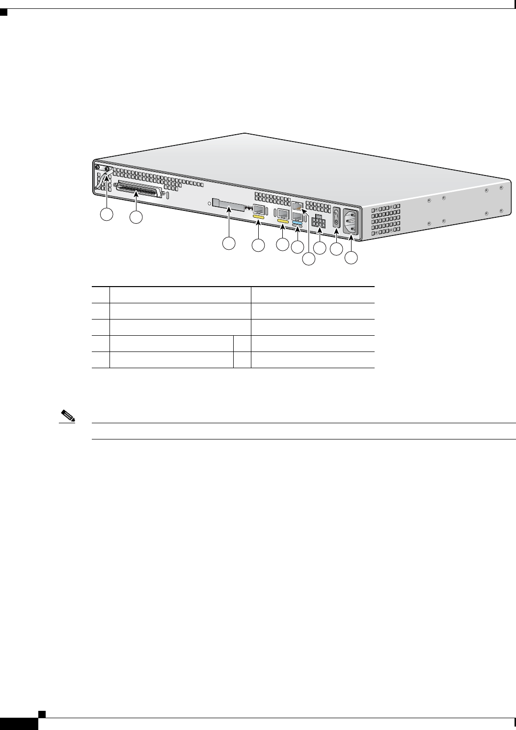
Identifying the Cisco VG224
Figure 1-1 shows the back panel and identifies the features of the Cisco VG224.
Figure 1-1 Identifying the Cisco VG224
• RJ-21 analog voice interface
• FE ports: 2
• External compact flash memory card
88838
VG224-24FXS
1-2
Cisco VG224 Voice Gateway Software Configuration Guide
OL-5005-01
Chapter 1 Understanding Interface Numbering and Cisco IOS Software Basics
Port Numbering Conventions
Port Numbering Conventions
The Cisco VG224 is used as an example. See Figure 1-2 on page 1-2.
Figure 1-2 Back-Panel Functions and Options (Cisco VG224 shown)
Note The Console port is above the AUX port.
Port numbering convention for the Cisco VG224 is as follows:
• Analog foreign exchange station (FXS) voice port numbering begins at 2/0 and extends up to 2/23.
• An external compact flash memory card is numbered CF 0.
• 10/100BASE-T Fast Ethernet ports are numbered Fast Ethernet 0/0 and Fast Ethernet 0/1, from right
to left.
1Chassis ground connection 6AUX port
2RJ-21 connector 7Console port
3Compact flash port 8DC power input1
1. This is not a redundant failover power supply connection. You must use either AC
or DC.
4Fast Ethernet port 1 9On/off switch
5Fast Ethernet port 0 10 AC power input
95914
2
456
7
89
10
3
1
VG224-24FXS

1-3
Cisco VG224 Voice Gateway Software Configuration Guide
OL-5005-01
Chapter 1 Understanding Interface Numbering and Cisco IOS Software Basics
Understanding Cisco IOS Software Basics
Understanding Cisco IOS Software Basics
This section describes what you need to know about the Cisco IOS software before you configure the
router using the command-line interface (CLI). This chapter includes the following:
• Getting Help, page 1-3
• Command Modes, page 1-3
• Undoing a Command or Feature, page 1-4
• Saving Configuration Changes, page 1-5
• Where to Go Next, page 1-5
Understanding these concepts will save time as you begin to use the CLI. If you have never used
Cisco IOS software or need a refresher, take a few minutes to read this chapter before you proceed to the
next chapter.
If you are already familiar with Cisco IOS software, proceed to Chapter 2, “Using the setup Command.”
Getting Help
Use the question mark (?) and arrow keys to help you enter commands:
• For a list of available commands, enter a question mark:
Router> ?
• To complete a command, enter a few known characters followed by a question mark (with no space):
Router> s?
• For a list of command variables, enter the command followed by a space and a question mark:
Router> show ?
• To redisplay a command you previously entered, press the up arrow key. You can continue to press
the up arrow key for more commands.
Command Modes
The Cisco IOS user interface is divided into different modes. Each command mode permits you to
configure different components on your router. The commands available at any given time depend on
which mode you are currently in. Entering a question mark (?) at the prompt displays a list of commands
available for each command mode. Table 1-1 lists the most common command modes.

1-4
Cisco VG224 Voice Gateway Software Configuration Guide
OL-5005-01
Chapter 1 Understanding Interface Numbering and Cisco IOS Software Basics
Understanding Cisco IOS Software Basics
Timesaver Each command mode restricts you to a subset of commands. If you are having trouble entering a
command, check the prompt, and enter the question mark (?) for a list of available commands. You might
be in the wrong command mode or using the wrong syntax.
In the following example, notice how the prompt changes after each command to indicate a new
command mode:
Router> enable
Password:
<enable password>
Router# configure terminal
Router(config)# interface serial 0/0
Router#
%SYS-5-CONFIG_I: Configured from console by console
The last message is normal and does not indicate an error. Press Return to get the Router# prompt.
Note You can press Ctrl-Z in any mode to immediately return to enable mode (Router#), instead of entering
exit, which returns you to the previous mode.
Undoing a Command or Feature
If you want to undo a command you entered or disable a feature, enter the keyword no before most
commands; for example, no ip routing.
Ta b l e 1-1 Common Command Modes
Command Mode Access Method
Router Prompt
Displayed Exit Method
User EXEC Log in. Router> Use the logout
command.
Privileged EXEC From user EXEC mode,
enter the enable
command.
Router# To exit to user EXEC
mode, use the disable,
exit, or logout
command.
Global configuration From the privileged
EXEC mode, enter the
configure terminal
command.
Router (config)# To exit to privileged
EXEC mode, use the
exit or end command,
or press Ctrl-Z.
Interface configuration From the global
configuration mode,
enter the interface type
number command, such
as interface serial 0/0.
Router (config-if)# To exit to global
configuration mode, use
the exit command.
To exit directly to
privileged EXEC mode,
press Ctrl-Z.
1-5
Cisco VG224 Voice Gateway Software Configuration Guide
OL-5005-01
Chapter 1 Understanding Interface Numbering and Cisco IOS Software Basics
Upgrading to a New Cisco IOS Release
Saving Configuration Changes
You need to enter the copy running-config startup-config command to save your configuration changes
to nonvolatile random-access memory (NVRAM), so the changes are not lost if there is a system reload
or power outage. For example:
Router# copy running-config startup-config
Building configuration...
It might take a minute or two to save the configuration to NVRAM. After the configuration has been
saved, the following appears:
[OK]
Router#
Upgrading to a New Cisco IOS Release
To install or upgrade to a new Cisco IOS release, see How to Update/Upgrade Cisco IOS Software.
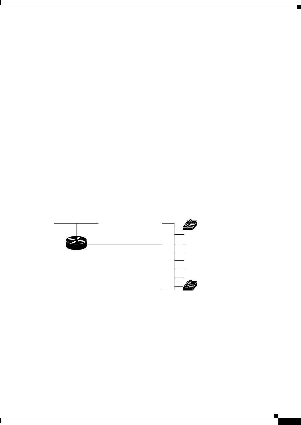
Cisco VG224 Deployment Scenario
Figure 1-3 shows a typical deployment scenario for the Cisco VG224 voice gateway.
Figure 1-3 Analog FXS User Interfaces with Metro Ethernet Interface
Where to Go Next
Now that you have learned some Cisco IOS software basics, you can begin to configure the router using
the CLI.
Remember that:
• You can use the question mark (?) and arrow keys to help you enter commands.
• Each command mode restricts you to a set of commands. If you have difficulty entering a command,
check the prompt and then enter the question mark (?) for a list of available commands. You might
be in the wrong command mode or using the wrong syntax.
VG224
RJ-21
Ethernet
Distribution
panel
103038
Analog
telephones

1-6
Cisco VG224 Voice Gateway Software Configuration Guide
OL-5005-01
Chapter 1 Understanding Interface Numbering and Cisco IOS Software Basics
Where to Go Next
• To disable a feature, generally enter the keyword no before the command; for example, no ip
routing.
• You need to save your configuration changes to NVRAM so the changes are not lost if there is a
system reload or power outage.
Proceed to Chapter 2, “Using the setup Command,” to begin configuring the router.

CHAPTER
2-1
Cisco VG224 Voice Gateway Software Configuration Guide
OL-5005-01
2
Using the setup Command
This chapter describes how to use the setup command facility to configure your Cisco VG224. The setup
command facility prompts you to enter information needed to start a router functioning quickly. The
facility steps you through a basic configuration, including LAN and WAN interfaces.
This chapter presents the following major topics:
• Before Starting Your Cisco VG224, page 2-1
• Using the setup Command, page 2-2
• Configuring Global Parameters, page 2-2
• Configuring Controller and Interface Parameters, page 2-5
• Completing the Configuration, page 2-6
• Where to Go Next, page 2-7
If you prefer to configure the router manually or you wish to configure a module or interface that is not
included in the setup command facility, proceed to “Chapter 3, “Configuring with the Command-Line
Interface,” for step-by-step instructions.
Before Starting Your Cisco VG224
Before you power on your Cisco VG224 and begin to use the setup command facility, make sure to
follow these steps:
Step 1 Set up the hardware as described in the installation documents for your Cisco VG224.
Step 2 Configure your PC terminal emulation program for 9600 baud, 8 data bits, no parity, and 1 stop bit.
Step 3 Determine which network protocols you are supporting.
Step 4 Determine the addressing plan for each network protocol.

2-2
Cisco VG224 Voice Gateway Software Configuration Guide
OL-5005-01
Chapter 2 Using the setup Command
Using the setup Command
Using the setup Command
The setup command facility is displayed in your PC terminal emulation program window.
To create a basic configuration for your Cisco VG224, do the following:
• Complete the steps in “Configuring Global Parameters” section on page 2-2.
• Complete the steps in “Configuring Controller and Interface Parameters” section on page 2-5.
• Complete the steps in “Completing the Configuration” section on page 2-6.
Note If you make a mistake while using the setup command facility, you can exit and run the facility again.
Press Ctrl-C, and type setup at the enable mode prompt (Router#).
Configuring Global Parameters
Step 1 Power on the Cisco VG224. The power switch is on the rear panel of the Cisco VG224, at the lower-right
corner, near the power cord.
Messages begin to appear in your terminal emulation program window.
Caution Do not press any keys on the keyboard until the messages stop. Any keys pressed during this time are
interpreted as the first command typed when the messages stop, which might cause the Cisco VG224 to
power off and start over. It takes a few minutes for the messages to stop.
The messages look similar to the following:
Note Much of the following example is largely for a Cisco VG224. The messages vary, depending on
the Cisco IOS software release, interface modules in place in your Cisco VG224, and feature set
you select. In addition, the word “Router” is the default prompt, and may appear elsewhere;
interpret this word as meaning “Cisco VG224.” The screen displays in this section are for
reference only and might not exactly reflect the messages on your console.
System Bootstrap, Version 12.3(20030210:192652) [INT-mcebu_sb.wk.0.3.2 102], DEVELOPMENT
SOFTWARE
Copyright (c) 1986-2003 by cisco Systems, Inc.
FPGA readonly version:0015001C
FPGA upgrade version :001A001E
Upgrade FPGA currently running
cvg224 processor with 131072 Kbytes of main memory
Main memory is configured to 64 bit mode with parity disabled
Upgrade ROMMON initialized
rommon 1 > dir slot0:
program load complete, entry point:0x80008000, size:0xa0e0
Directory of slot0:
2 9711556 -rw- vg224-i6s-mz-swell_2.0.4.1
9486 10051540 -rw- vg224-i6s-mz.pi3_dhcp
rommon 2 > b slot0:vg224-i6s-mz-swell_2.0.4.1

2-3
Cisco VG224 Voice Gateway Software Configuration Guide
OL-5005-01
Chapter 2 Using the setup Command
Configuring Global Parameters
program load complete, entry point:0x80008000, size:0xa0e0
program load complete, entry point:0x8001f000, size:0x942e80
Self decompressing the image
:#########################################################################################
########################## [OK]
Smart Init is enabled
smart init is sizing iomem
ID MEMORY_REQ TYPE
00045B 0X004A528C 24 Analog FXS's, 2 FE
0X000F3BB0 public buffer pools
0X00211000 public particle pools
TOTAL: 0X007A9E3C
If any of the above Memory Requirements are
"UNKNOWN", you may be using an unsupported
configuration or there is a software problem and
system operation may be compromised.
Rounded IOMEM up to:8Mb.
Using 12 percent iomem. [8Mb/64Mb]
Restricted Rights Legend
Use, duplication, or disclosure by the Government is
subject to restrictions as set forth in subparagraph
(c) of the Commercial Computer Software - Restricted
Rights clause at FAR sec. 52.227-19 and subparagraph
(c) (1) (ii) of the Rights in Technical Data and Computer
Software clause at DFARS sec. 252.227-7013.
cisco Systems, Inc.
170 West Tasman Drive
San Jose, California 95134-1706
Cisco Internetwork Operating System Software
IOS (tm) vg224 Software (vg224-I6S-M), Version 12.3(swell_2.0.4.1), CISCO DEVELOPMENT TEST
VERSION
Copyright (c) 1986-2003 by cisco Systems, Inc.
Compiled Tue 15-Jul-03 00:31 by lcheungb
Image text-base:0x6001F8F4, data-base:0x61044000
cisco VG224 (R527x) processor (revision 3.0) with 57344K/8192K bytes of memory.
Processor board ID FHK0720U00G
R527x CPU at 225Mhz, Implementation 40, Rev 3.1
Bridging software.
1 On-Board Twenty-Four FXS Analog Voice Module
2 FastEthernet/IEEE 802.3 interface(s)
DRAM configuration is 64 bits wide with parity disabled.
63K bytes of non-volatile configuration memory.
System fpga version is 230024
System readonly fpga version is 20001E
Option for system fpga is 'system'.
31360K bytes of ATA Slot0 CompactFlash (Read/Write)
System is running with system fpga version 230024 (upgrade)
Option set for fpga is 'system'.
Press RETURN to get started!
--- System Configuration Dialog ---

2-4
Cisco VG224 Voice Gateway Software Configuration Guide
OL-5005-01
Chapter 2 Using the setup Command
Configuring Global Parameters
Would you like to enter the initial configuration dialog? [yes/no]: yes
At any point you may enter a question mark '?' for help.
Use ctrl-c to abort configuration dialog at any prompt.
Default settings are in square brackets '[]'.
Step 2 When the following message appears, enter yes to begin the initial configuration dialog:
Would you like to enter the initial configuration dialog? [yes/no]:
Note If you answer no to this message, you are prompted to terminate AutoInstall. AutoInstall is a
procedure that configures a new Cisco VG224 based on the configuration of an existing Cisco
VG224.
If you terminate AutoInstall, you enter the Cisco IOS software CLI.
Note The number of interfaces shown depends on the Cisco VG224.
Step 3 When the following message appears, press Return to see the current interface summary:
First, would you like to see the current interface summary? [yes]:
Any interface listed with OK? value “NO” does not have a valid configuration
Interface IP-Address OK? Method Status Protocol
FastEthernet0/0 unassigned NO unset up down
Step 4 Enter a host name for the Cisco VG224:
Configuring global parameters:
Enter host name [Router]: VG224
The enable secret is a password used to protect access to privileged EXEC and
configuration modes. This password, after entered, becomes encrypted in the configuration.
Step 5 Enter an enable secret password. This password is encrypted (more secure) and cannot be seen when
viewing the configuration.
Enter enable secret:
xxxx
The enable password is used when you do not specify an enable secret password, with some
older software versions, and some boot images.
Step 6 Enter an enable password that is different from the enable secret password. This password is not
encrypted (less secure) and can be seen when viewing the configuration.
Enter enable password:
guessme
The virtual terminal password is used to protect access to the router over a network
interface.
Step 7 Enter the virtual terminal password, which prevents unauthenticated access to the router through ports
other than the console port:
Enter virtual terminal password:
guessagain
Step 8 Respond to the following prompts as appropriate for your network:
Configure SNMP Network Management? [yes]:

2-5
Cisco VG224 Voice Gateway Software Configuration Guide
OL-5005-01
Chapter 2 Using the setup Command
Configuring Controller and Interface Parameters
Community string [public]:
Configure LAT? [no]:
Configure IP? [yes]:
Configure IGRP routing? [yes]:
Your IGRP autonomous system number [1]: 1
Note If you answer no to IGRP, you are prompted to configure RIP.
Configure bridging? [no]:
Step 9 (Optional) Configure CHAP:
All users dialing in through the PRI will need to be
authenticated using CHAP. The username and password are
case sensitive.
Do you want to enter username and passwords for PPP authentication ? [no]:
Step 10 Configure the ISDN switch type for PRI.
The following ISDN switch types are available:
[0] none............If you do not want to configure ISDN
[1] primary-4ess....AT&T 4ESS switch type for US and Canada
[2] primary-5ess....AT&T 5ESS switch type for US and Canada
[3] primary-dms100..Northern Telecom switch type for US and Canada
[4] primary-net5....European switch type for NET5
[5] primary-ni......National ISDN Switch type for the U.S
[6] primary-ntt.....Japan switch type
[7] primary-qsig....QSIG switch type
[8] primary-ts014...Australian switch type
Choose ISDN PRI Switch Type [2]:
Note BRI is not currently supported.
Configuring Controller and Interface Parameters
From this point on in the setup process, the prompts you see vary depending on the interface cards
installed in your Cisco VG224. The following sections provide examples of the setup steps for card.
Refer to the sections appropriate to your Cisco VG224.
Configuration examples include the following:
• Configuring Fast Ethernet and Serial Interface Parameters, page 2-5
• Configuring Fast Ethernet and Serial Interface Parameters, page 2-5
When you complete the setup steps for your interface modules, go to Completing the Configuration,
page 2-6 for directions on saving your configuration.
Configuring Fast Ethernet and Serial Interface Parameters
This section illustrates the following:

2-6
Cisco VG224 Voice Gateway Software Configuration Guide
OL-5005-01
Chapter 2 Using the setup Command
Completing the Configuration
• Fast Ethernet Interface Configuration
Fast Ethernet Interface Configuration
This section contains a sample configuration for the Fast Ethernet interface. Enter the values appropriate
for your Cisco VG224 and network. The messages you see may vary.
Do you want to configure FastEthernet0/0 interface [yes]:
Use the 100 Base-TX (RJ-45) connector? [yes]:
Operate in full-duplex mode? [no]:
Configure IP on this interface? [no]: yes
IP address for this interface: 6.0.0.1
Number of bits in subnet field [0]:
Class A network is 6.0.0.0, 0 subnet bits, mask is /8
Configure IPX on this interface? [yes]:
IPX network number [1]:
Need to select encapsulation type
[0] sap (IEEE 802.2)
[1] snap (IEEE 802.2 SNAP)
[2] arpa (Ethernet_II)
[3] novell-ether (Novell Ethernet_802.3)
Enter the encapsulation type [2]:
Completing the Configuration
When you have provided all the information prompted for by the setup command facility, the
configuration appears.
Note For sample configurations, see Appendix A, “Cisco VG224 Configuration Example.”
To complete your configuration, do the following:
Step 1 A setup command facility prompt asks if you want to save this configuration, with the following options:
[0] Go to the IOS command prompt without saving this config.
[1] Return back to the setup without saving this config.
[2] Save this configuration to nvram and exit.
If you answer 0, the configuration information you entered is not saved, and you return to the Cisco
VG224 enable prompt (Router#). Type setup to return to the System Configuration Dialog.
If you answer 1, you return to setup without saving the configuration.
If you answer 2, the configuration is saved and you are returned to the user EXEC prompt (Router>).
Step 2 When the messages stop appearing on your screen, press Return to get the Router> prompt.
Step 3 The Router> prompt indicates that you are now at the command-line interface (CLI) and you have just
completed a basic Cisco VG224 configuration. However, this is not a complete configuration. At this
point you have two choices:
• Run the setup command facility again and create another configuration. Enter the following:
Router> enable
Password:
password
Router# setup

2-7
Cisco VG224 Voice Gateway Software Configuration Guide
OL-5005-01
Chapter 2 Using the setup Command
Where to Go Next
• Modify the existing configuration or configure additional features with the CLI as described in
Chapter 3, “Configuring with the Command-Line Interface.”
Where to Go Next
At this point you can proceed to the following:
• “Chapter 3, “Configuring with the Command-Line Interface,” to learn how to use the CLI to
configure additional features.
• The Cisco IOS software configuration guide and command reference publications for more
advanced configuration topics. These publications are available on Cisco.com and the
Documentation CD-ROM, or you can order printed copies. For more information, refer to
“Obtaining Documentation” section on page x.

2-8
Cisco VG224 Voice Gateway Software Configuration Guide
OL-5005-01
Chapter 2 Using the setup Command
Where to Go Next

CHAPTER
3-1
Cisco VG224 Voice Gateway Software Configuration Guide
OL-5005-01
3
Configuring with the Command-Line Interface
This chapter describes how to use the Cisco IOS software command-line interface (CLI) to configure
basic Cisco VG224 functionality.
This chapter presents the following major topics:
• Configuring the Host Name and Password, page 3-2
• Configuring Fast Ethernet Interfaces, page 3-4
• Saving Configuration Changes, page 3-5
• Where to Go Next, page 3-5
Follow the procedures in this chapter to configure the Cisco VG224 manually or, if you want to, change
the configuration after you have run the setup command facility (see “Using the setup Command”
section on page 2-2).
This chapter does not describe every configuration possible—only a small portion of the most commonly
used configuration procedures. For advanced configuration topics, refer to the Cisco IOS configuration
guide and command reference publications. See “Obtaining Documentation” section on page x.
Note If you skipped the previous chapter, Chapter 2, “Using the setup Command,” and you have never
configured a Cisco VG224, go back to that chapter and read it now. The chapter contains important
information you need to configure your Cisco VG224 successfully.

3-2
Cisco VG224 Voice Gateway Software Configuration Guide
OL-5005-01
Chapter 3 Configuring with the Command-Line Interface
Configuring the Host Name and Password
Configuring the Host Name and Password
One of the first configuration tasks you might want to do is to configure the host name and set an
encrypted password. Configuring a host name allows you to distinguish multiple Cisco VG224s and
routers from each other. Setting an encrypted password allows you to prevent unauthorized configuration
changes.
Command Purpose
Step 1 Router> enable
Password:
password
Router#
Enters enable mode. Enter the password.
You have entered enable mode when the prompt
changes to Router#.
Step 2 Router# configure terminal
Enter configuration commands, one per line.
End with CNTL/Z.
Router(config)#
Enters global configuration mode. You have
entered global configuration mode when the
prompt changes to Router(config)#.
Step 3 Router(config)# hostname VG224
Router(config)#
Changes the name of the Cisco VG224 to a
meaningful name. Substitute your host name for
Router.
Step 4 Router(config)# enable secret guessme Enters an enable secret password. This password
provides access to privileged EXEC mode. When
you enter enable at the user EXEC prompt
(Router> ), you must enter the enable secret
password to gain access to configuration mode.
Substitute your enable secret password for
guessme.
Step 5 Router(config)# line con 0
Router(config-line)# exec-timeout 0 0
Router(config-line)# exit
Router(config)#
Enters line configuration mode to configure the
console port. When you enter line configuration
mode, the prompt changes to
Router(config-line)#.
Prevents the Cisco VG224’s EXEC facility from
timing out if you do not type any information on
the console screen for an extended period.
Exits back to global configuration mode.

3-3
Cisco VG224 Voice Gateway Software Configuration Guide
OL-5005-01
Chapter 3 Configuring with the Command-Line Interface
Configuring the Host Name and Password
Verifying the Host Name and Password
To verify that you configured the correct host name and password:
Step 1 Enter the show config command:
Router(config)# show config
Using 1888 out of 126968 bytes
!
version XX.X
.
.
.
!
hostname VG224
!
enable secret 5 $1$60L4$X2JYOwoDc0.kqa1loO/w8/
.
.
.
Check the host name and encrypted password displayed near the top of the command output.
Step 2 Exit global configuration mode and attempt to reenter it using the new enable password:
Router# exit
.
.
.
Router con0 is now available
Press RETURN to get started.
Router> enable
Password:
guessme
Router#
Tip If you are having trouble, ensure the following:
• Caps Lock is off.
• You entered the correct passwords. Passwords are case sensitive.

3-4
Cisco VG224 Voice Gateway Software Configuration Guide
OL-5005-01
Chapter 3 Configuring with the Command-Line Interface
Configuring Fast Ethernet Interfaces
Configuring Fast Ethernet Interfaces
To configure a Fast Ethernet interface, use the configuration software provided with your Cisco VG224
or network module, if any. Otherwise, for greatest power and flexibility, use configuration mode (manual
configuration).
Note Before you begin, disconnect all WAN cables from the Cisco VG224 to keep it from trying to run the
AutoInstall process. The Cisco VG224 tries to run AutoInstall whenever you power it on if there is a
WAN connection on both ends and the Cisco VG224 does not have a valid configuration file stored in
NVRAM (for instance, when you add a new interface). It can take several minutes for the Cisco VG224
to determine that AutoInstall is not connected to a remote TCP/IP host.
This section describes basic configuration, including enabling the interface and specifying IP routing.
Depending on your own requirements and the protocols you plan to route, you might also need to enter
other configuration commands.
Before you begin configuring the interfaces, make sure to do the following:
• Connect a console to the Cisco VG224.
• Power on the Cisco VG224.
Command Purpose
Step 1 Router> enable
Password:
password
Router#
Enters enable mode. Enter the password.
You have entered enable mode when the prompt
changes to Router#.
Step 2 Router# configure terminal
Enter configuration commands, one per line.
End with CNTL/Z.
Router(config)#
Enters global configuration mode. You have
entered global configuration mode when the
prompt changes to Router(config)#.
Step 3 Router# ip routing
Router# ipx routing
Enables routing protocols as required for your
global configuration. This example uses IP routing
and Internetwork Packet Exchange (IPX) routing.
Step 4 Router(config)# interface fastethernet 0/0
Router(config-if)#
Enters interface configuration mode. You have
entered interface configuration mode when the
prompt changes to Router(config-if)#.
Step 5 Router(config-if)# ip address 172.16.74.3
255.255.255.0
Assigns an IP address and subnet mask to the
interface.
Step 6 Router(config-if)# ipx network B005 Configures routing protocols on the interface. You
must have previously enabled these protocols as
part of global configuration. In this example, IPX
is being configured on the interface.

3-5
Cisco VG224 Voice Gateway Software Configuration Guide
OL-5005-01
Chapter 3 Configuring with the Command-Line Interface
Saving Configuration Changes
Saving Configuration Changes
To prevent the loss of the Cisco VG224 configuration, save it to NVRAM:
Where to Go Next
At this point you can proceed to the following:
• The Cisco IOS software configuration guide and command reference publications for more
advanced configuration topics. These publications are available on Cisco.com or on the
Documentation CD-ROM, or you can order printed copies.
• Cisco System Error Messages, Release 12.3(4)T, and Cisco Debug Command Reference, Release
12.3(4)T provide troubleshooting information. For these and other documents, see Obtaining
Documentation, page x.
Step 7 Router(config-if)# exit Exits back to global configuration mode.
Repeat Step 4 through Step 6 if your Cisco VG224
has more than one interface that you need to
configure.
Step 8 Router(config-if)# Ctrl-z
Router#
When you finish configuring interfaces, returns to
enable mode.
Command Purpose
Command Purpose
Step 1 Router> enable
Password:
password
Router#
Enters enable mode. Enter the password.
You have entered enable mode when the prompt
changes to Router#.
Step 2 Router# copy running-config startup-config Saves the configuration changes to NVRAM so
that they are not lost during resets, power cycles,
or power outages.
Step 3 Router(config-if)# Ctrl-z
Router#
%SYS-5-CONFIG_I: Configured from console by
console
Returns to enable mode.
This message is normal and does not indicate an
error.

3-6
Cisco VG224 Voice Gateway Software Configuration Guide
OL-5005-01
Chapter 3 Configuring with the Command-Line Interface
Where to Go Next

CHAPTER
4-1
Cisco VG224 Voice Gateway Software Configuration Guide
OL-5005-01
4
Configuring Voice over IP
This chapter explains how to configure voice interfaces and ports, which convert telephone voice signals
for transmission over an IP network.
This chapter presents the following major topics:
• Prerequisites, page 4-1
• Configuring the Voice Interface, page 4-1
• Where to Go Next, page 4-3
Voice over IP (VoIP) enables your Cisco VG224 to carry live voice traffic (for example, telephone calls
and faxes) over an IP network. VoIP offers the following benefits:
• Unified voice and data trunking
• Plain old telephone service (POTS)-Internet telephony gateways
Prerequisites
Before you can configure your Cisco VG224 to use VoIP, you must first establish a working IP network.
Configuring the Voice Interface
Whenever you install a new interface, or if you want to change the configuration of an existing interface,
you must configure the interface. If you replace a module that was already configured, the Cisco VG224
recognizes it and brings up the interface in the existing configuration.
Before you configure an interface, have the following information available:
• Protocols you plan to route on the new interface
• IP addresses, subnet masks, network numbers, zones, or other information related to the routing
protocol
Timesaver Obtain this information from your system administrator or network plan before you begin configuring
your Cisco VG224.
To configure a voice interface, you must use configuration mode (manual configuration). In this mode,
you can enter Cisco IOS commands through the command line interface (CLI).

4-2
Cisco VG224 Voice Gateway Software Configuration Guide
OL-5005-01
Chapter 4 Configuring Voice over IP
Configuring the Voice Interface
To configure the voice interface configuration mode, follow this procedure:
Step 1 Connect a console to the Cisco VG224. If you need instructions for connecting a console, refer to the
installation chapter of your Cisco VG224 installation and configuration guide.
Step 2 Power on the Cisco VG224. If the current configuration is no longer valid, after about one minute you
see the following prompt:
Would you like to enter the initial dialog? [yes/no]:
Answer no. You now enter the normal operating mode of the Cisco VG224.
Note If the current configuration is valid, you enter the normal operating mode automatically.
Step 3 After a few seconds, you see the user EXEC prompt (Router>). Type enable and the password to enter
enable mode:
Router> enable
Password: <
password
>
Configuration changes can be made only in enable mode. The prompt changes to the privileged EXEC
(enable) prompt (Router#):
Router#
Step 4 Enter the configure terminal command to enter configuration mode:
Router# configure terminal
Router(config)#
The Cisco VG224 enters global configuration mode, indicated by the Router(config)# prompt.
Step 5 If you have not configured the Cisco VG224 before, or want to change the configuration, use Cisco IOS
commands to configure global parameters, passwords, network management, and routing protocols. In
this example, IP routing is enabled:
Router(config)# ip routing
For complete information about global configuration commands, refer to the Cisco IOS configuration
guides and command references.
Step 6 If you have not already done so, configure the network module or WAN interface card that you plan to
use for IP traffic. For instructions, see your Cisco VG224’s hardware installation and software
configuration guides or the configuration note for the network module or WAN interface card.
Step 7 To configure another interface, enter the exit command to return to the Router(config)# prompt.
Step 8 To configure the Cisco VG224 for voice traffic, refer to the VoIP references in Prerequisites, page 4-1.
Step 9 When you finish configuring interfaces, exit configuration mode and return to the enable prompt by
pressing Ctrl-Z. To see the current operating configuration, including any changes you just made, enter
the show running-config command:
Router# show running-config
To see the configuration currently stored in NVRAM, enter the show startup-config command at the
enable prompt:
Router# show startup-config

4-3
Cisco VG224 Voice Gateway Software Configuration Guide
OL-5005-01
Chapter 4 Configuring Voice over IP
Where to Go Next
Step 10 The results of the show running-config and show startup-config commands differ from each other if
you have made changes to the configuration, but have not yet written them to NVRAM. To write your
changes to NVRAM, making them permanent, enter the copy running-config startup-config command
at the enable prompt:
Router# copy running-config startup-config
Building configuration. . .
[OK]
Router#
The Cisco VG224 is now configured to boot in the new configuration.
Where to Go Next
For further information on VoIP configuration procedures and debug commands, refer to the following:
• Cisco IOS Voice Configuration Library.

4-4
Cisco VG224 Voice Gateway Software Configuration Guide
OL-5005-01
Chapter 4 Configuring Voice over IP
Where to Go Next

A-1
Cisco VG224 Voice Gateway Software Configuration Guide
OL-5005-01
APPENDIX
A
Cisco VG224 Configuration Example
This appendix presents the following sample configurations for the Cisco VG224.
Current configuration : 2612 bytes
!
version 12.3(4)T
service timestamps debug datetime msec
service timestamps log datetime msec
no service password-encryption
!
hostname swell-China
!
!
ip subnet-zero
!
!
!
!
!
!
!
!
!
!
no voice hpi capture buffer
no voice hpi capture destination
!
!
mta receive maximum-recipients 0
!
!
!
!
!
!
interface FastEthernet0/0
ip address 1.3.21.55 255.255.0.0
ip nat inside
duplex auto
speed auto
!
interface FastEthernet0/1
ip address 1.2.111.1 255.255.0.0
duplex auto
speed auto
!
ip http server

A-2
Cisco VG224 Voice Gateway Software Configuration Guide
OL-5005-01
Appendix A Cisco VG224 Configuration Example
no ip http secure-server
ip classless
ip route 0.0.0.0 0.0.0.0 1.2.0.1
!
!
!
!
!
call rsvp-sync
!
voice-port 2/0
disc_pi_off
input gain 10
output attenuation 10
playout-delay minimum low
cptone HK
timing digit 53
description cflow1
music-threshold -50
bearer-cap Speech
station-id name ashwin
station-id number 1000
caller-id enable
ren 3
disconnect-ack
loss-plan plan4
idle-voltage high
!
voice-port 2/1
disc_pi_off
input gain 10
output attenuation 10
playout-delay minimum low
cptone HK
timing digit 53
description cflow1
music-threshold -50
bearer-cap Speech
station-id name ashwin
station-id number 1000
caller-id enable
ren 3
disconnect-ack
loss-plan plan4
idle-voltage high
!
voice-port 2/2
cptone HK
!
voice-port 2/3
cptone HK
!
voice-port 2/4
cptone HK
!
voice-port 2/5
cptone HK
!
voice-port 2/6
cptone HK
!
voice-port 2/7
cptone HK
!

A-3
Cisco VG224 Voice Gateway Software Configuration Guide
OL-5005-01
Appendix A Cisco VG224 Configuration Example
voice-port 2/8
cptone HK
!
voice-port 2/9
cptone HK
!
voice-port 2/10
cptone HK
!
voice-port 2/11
!
voice-port 2/12
!
voice-port 2/13
!
voice-port 2/14
!
voice-port 2/15
!
voice-port 2/16
!
voice-port 2/17
!
voice-port 2/18
!
voice-port 2/19
!
voice-port 2/20
!
voice-port 2/21
!
voice-port 2/22
!
voice-port 2/23
!
!
mgcp profile default
!
dial-peer cor custom
!
!
!
dial-peer voice 1 pots
service stcapp 1000
port 2/0
!
dial-peer voice 2 pots
service stcapp 2000
port 2/1
!
dial-peer voice 3 pots
service stcapp 1002
port 2/2
!
dial-peer voice 4 pots
service stcapp 1003
port 2/3
!
dial-peer voice 5 pots
service stcapp 1004
port 2/4
!
dial-peer voice 6 pots
service stcapp 1005

A-4
Cisco VG224 Voice Gateway Software Configuration Guide
OL-5005-01
Appendix A Cisco VG224 Configuration Example
port 2/5
!
dial-peer voice 10 voip
destination-pattern 2...
session target ipv4:1.2.125.57
codec g711ulaw
!
dial-peer voice 7 pots
service stcapp 1006
port 2/6
!
dial-peer voice 8 pots
service stcapp 1007
port 2/7
!
dial-peer voice 9 pots
service stcapp 1008
port 2/8
!
dial-peer voice 11 pots
service stcapp 1009
port 2/9
!
dial-peer voice 12 pots
service stcapp 1010
port 2/10
!
!
!
line con 0
exec-timeout 0 0
speed 115200
line aux 0
line vty 0 4
login
!
end

B-1
Cisco VG224 Voice Gateway Software Configuration Guide
OL-5005-01
APPENDIX
B
Formatting the Compact Flash Memory Cards
This appendix describes how to format the compact flash memory into a Class B flash file system, known
as the low-end file system (LEFS), or into a Class C flash file system, which is similar to the standard
DOS file system. It also describes how to perform file and directory operations in each file system.
This appendix presents the following major topics:
• Formatting Procedures for Compact Flash Memory Cards, page B-1
• File and Directory Operations, page B-4
Formatting Procedures for Compact Flash Memory Cards
The following sections describe formatting procedures for internal and external compact flash memory
cards.
Formatting Procedures
We recommend that you erase (Class B) or format (Class C) new compact flash memory cards to
initialize them with either a Class B or Class C flash file system. This ensures proper formatting and
enables the ROM monitor to recognize and boot the flash.
Note A compact flash memory card formatted with the standard DOS file system does not support booting
from the ROM monitor.
Determining the File System on a Compact Flash Memory Card
To determine the file system of an external compact flash memory card, enter the show slot0: all
command. To determine the file system of an internal compact flash memory card, enter the
show flash: all command.
• If geometry and format information is not displayed, the card is formatted with a Class B flash file
system.
• If geometry and format information is displayed, the card is formatted with a Class C flash file
system.

B-2
Cisco VG224 Voice Gateway Software Configuration Guide
OL-5005-01
Appendix B Formatting the Compact Flash Memory Cards
Formatting Procedures for Compact Flash Memory Cards
The following examples show sample outputs for Class B and Class C flash file systems:
External Card with Class B Flash File System
The geometry and format information is not displayed for this format:
Router# show slot0: all
Partition Size Used Free Bank-Size State Copy
Mode
1 31360K 6502K 24857K 0K Read/Write Direct
Slot0 CompactFlash directory:
File Length Name/status
addr fcksum ccksum
1 6658376 cvg224-i-mz
0x40 0xE0FF 0xE0FF
[6658440 bytes used, 25454200 available, 32112640 total]
31360K bytes of ATA Slot0 CompactFlash (Read/Write)
Chip information NOT available.
External Card with Class C Flash File System
The geometry and format information is displayed in this forma:
Router# show slot0: all
-#- --length-- -----date/time------ path
1 6658376 Mar 01 1993 04:27:46 cvg224-i-mz
25268224 bytes available (6664192 bytes used)
******** ATA Flash Card Geometry/Format Info ********
ATA CARD GEOMETRY
Number of Heads: 4
Number of Cylinders 490
Sectors per Cylinder 32
Sector Size 512
Total Sectors 62720
ATA CARD FORMAT
Number of FAT Sectors 31
Sectors Per Cluster 8
Number of Clusters 7796
Number of Data Sectors 62560
Base Root Sector 155
Base FAT Sector 93
Base Data Sector 187
Internal Card with Class B Flash File System
The geometry and format information is not displayed for this format:
Router# show flash: all
Partition Size Used Free Bank-Size State Copy
Mode
1 125184K 20390K 104793K 0K Read/Write
Direct

B-3
Cisco VG224 Voice Gateway Software Configuration Guide
OL-5005-01
Appendix B Formatting the Compact Flash Memory Cards
Formatting Procedures for Compact Flash Memory Cards
System CompactFlash directory:
File Length Name/status
addr fcksum ccksum
1 6658376 cvg224-i-mz
0x40 0xE0FF 0xE0FF
2 14221136 cvg224-telcoent-mz
0x6599C8 0x5C3D 0x5C3D
[20879640 bytes used, 107308776 available, 128188416 total]
125184K bytes of ATA System CompactFlash (Read/Write)
Chip information NOT available.
Internal Card with Class C Flash File System
The geometry and format information is displayed in this format:
11# show flash: all
-#- --length-- -----date/time------ path
1 6658376 Mar 01 1993 04:27:46 cvg224-i-mz
25268224 bytes available (6664192 bytes used)
******** ATA Flash Card Geometry/Format Info ********
ATA CARD GEOMETRY
Number of Heads: 4
Number of Cylinders 490
Sectors per Cylinder 32
Sector Size 512
Total Sectors 62720
ATA CARD FORMAT
Number of FAT Sectors 31
Sectors Per Cluster 8
Number of Clusters 7796
Number of Data Sectors 62560
Base Root Sector 155
Base FAT Sector 93
Base Data Sector 187
Formatting Compact Flash Memory as a Class B Flash File System
Use these formatting commands to:
• Format compact flash memory cards with a Class B flash file system (LEFS)
• Remove the files from a compact flash memory card previously formatted with a Class B flash file
system
For external compact flash memory cards, enter the erase slot0: command.
For internal compact flash memory cards, enter the erase flash: command.
The following example shows sample output for formatting an external compact flash memory card with
a Class B flash file system:
Router# erase slot0:
Erasing the slot0 filesystem will remove all files! Continue? [confirm]
Current DOS File System flash card in slot0: will be formatted into Low
End File System flash card! Continue? [confirm]
Erasing device...

B-4
Cisco VG224 Voice Gateway Software Configuration Guide
OL-5005-01
Appendix B Formatting the Compact Flash Memory Cards
File and Directory Operations
eeeeeeeeeeeeeeeeeeeeeeeeeeeeeeeeeeeeeeeeeeeeeeeeeeeeeeeeeeeeeeeeeeeeeeeeeeeeeeeeeeeeeeeeee
eeeeeeeeeeeeeeeeeeeeeeeeeeeeeeeeeeeeeeeeeeeeeeeeeeeeeeeeeeeeeeeeeeeeeeeeeeeeeeeeeeeeeeeeee
eeeeeeeeeeeeeeeeeeeeeeeeeeeeeeeeeeeeeeeeeeeeeeeeeeeeeeeeeeeeeeeeeeeeeeeeeeeeeeeeeeeeeeeeee
eeeeeeeeeeeeeeeeeeeeeeeeeeeeeeeeeeeeeeeeeeeeeeeeeeeeeeeeeeeeeeeeeeeeeeeeeeeeeeeeeeeeeeeeee
eeeeeeeeeeeeeeeeeeeeeeeeeeeeeeeeeeeeeeeeeeeeeeeeeeeeeeeeeeeeeeeeeeeeeeeeeeeeeeeeeeeeeeeeee
eeeeeeeeeeeeeeeeeeeeeeeeeeeeeeeeeeeeeeee
...erased
Erase of slot0: complete
Formatting Compact Flash Memory as a Class C File System
Use these formatting commands to do the following:
• Format compact flash memory cards with a Class C flash file system
• Remove the files from a compact flash memory card previously formatted with a Class C flash file
system
For external compact flash memory cards, enter the format slot0: command.
For internal compact flash memory cards, enter the format flash: command.
The following example shows sample output for formatting an internal compact flash memory card with
a Class C flash file system:
Router# format flash:
Format operation may take a while. Continue? [confirm]
Format operation will destroy all data in "flash:". Continue? [confirm]
Enter volume ID (up to 64 chars)[default flash]:
Current Low End File System flash card in flash will be formatted into DOS
File System flash card! Continue? [confirm]
Format:Drive communication & 1st Sector Write OK...
Writing Monlib sectors ...................................................................
Monlib write complete
..
Format:All system sectors written. OK...
Format:Total sectors in formatted partition:250592
Format:Total bytes in formatted partition:128303104
Format:Operation completed successfully.
Format of flash complete
File and Directory Operations
The following sections describe file and directory operations for internal and external Cisco flash
memory cards. File and directory operations vary according to the formatted file system—Class B or
Class C.
Operations for Use with Class B Flash File System
The following file operations are useful for compact flash memory cards formatted with a Class B flash
file system.
Copying Files
To copy files to another location, enter the copy {flash: | slot0:} command.

B-5
Cisco VG224 Voice Gateway Software Configuration Guide
OL-5005-01
Appendix B Formatting the Compact Flash Memory Cards
File and Directory Operations
The following example shows sample output for copying a Cisco IOS file from an internal compact flash
memory card (flash:) to an external compact flash memory card (slot0:):
Router# copy flash:cvg224-i-mz.tmp slot0:
Destination filename [cvg224-i-mz.tmp]?
Erase slot0:before copying?
[confirm]nCCCCCCCCCCCCCCCCCCCCCCCCCCCCCCCCCCCCCCCCCCCCCCCCCCCCCCCCCCCCCCCCCCCCCCCCCCCCCCCC
CCCCCCCCCCCCCCCCCCCCCCCCCCCCCCCCCCCCCCCCCCCCCCCCCCCCCCCCCCCCCCCCCCCCCCCCCCCCCCCCCCCCCCCCCC
CCCCCCCCCCCCCCCCCCCCCCCCCCCCCCCCCCCCCCCCCCCCCCCCCCCCCCCCCCCCCCCCCCCCCCCCCCCCCCCCCCCCCCCCCC
CCCCCCCCCCCCCCCCCCCCCCCCCCCCCCCCCCCCCCCCCCCCCCCCCCCCCCCCCCCCCCCCCCCCCCCCCCCCCCCCCCCCCCCCCC
CCCCCCCCCCCCCCCCCCCCCCCCCCCCCCCCCCCCCCCCCCCCCCCCCCCCCCCCCCCCCCCCCCCCCCCCCCCCCCCCCCCCCCCCCC
CCCCCCCCCCCCCCCCCCCCCCCCCCCCCCCCCCCCCCCCCCCCCCCCCCCCCCCCCCCCCCCCCCCCCCCCCCCCCCCCCCCCCCCCCC
CCCCCCCCCCCCCCCCCCCCCCCCCCCCCCCCCCCCCCCCCCCCCCCCCCCCCCCCCCCCCCCCCCCCCCCCCCCCCCCCCCCCCCCCCC
CCCCCCCCCCCCCCCCCCCCCCCCCCCCCCCCCCCCCCCCCCCCCCCCCCCCCCCCCCCCCCCCCCCCCCCCCCCCCCCCCCCCCCCCCC
CCCCCCCCCCCCCCCCCCCCCCCCCCCCCCCCCCCCCCCCCCCCCCCCCCCCCCCCCCCCCCCCCCCCCCCCCCCCCCCCCCCCCCCCCC
CCCCCCCCCCCCCCCCCCCCCCCCCCCCCCCCCCCCCCCCCCCCCCCCCCCCCCCCCCCCCCCCCCCCCCCCCCCCCCCCCCCCCCCCCC
CCCCCCCCCCCCCCCCCCCCCCCCCCCCCCCCCCCCCCCCCCCCCCCCCCCCCCCCCCCCCCCCCCCCCCCCCCCCCCCCCCCCCCCCCC
CCCCCCCCCCCCCCCCCCCCCCCCCCCCCCCCCCCCCCCCCCCCCCCCCCCCCCCCCCCCCCCCCCCCCCCCCCCCCCCCCCCCCCCCCC
CCCCCCCCCCCCCCCCCCCCCCCCCCCCCCCCCCCCCCCCCCCCCCCCCCCCCCCCCCCCCCCCCCCCCCCCCCCCCCCCCCCCCCCCCC
CCCCCCCCCCCCCCCCCCCCCCCCCCCCCCCCCCCCCCCCCCCCCCCCCCCCCCCCCCCCCCCCCCCCCCCCCCCCCCCCCCCCCCCCCC
CCCCCCCCCCCCCCCCCCCCCCCCCCCCCCCCCCCCCCCCCCCCCCCCCCCCCCCCCCCCCCCCCCCCCCCCCCCCCCCCCCCCCCCCCC
CCCCCCCCCCCCCCCCCCCCCCCCCCCCCCCCCCCCCCCCCCCCCCCCCCCCCCCCC
Verifying checksum... OK (0xC68E)
6458584 bytes copied in 67.788 secs (96396 bytes/sec)
The following example shows sample output for copying a configuration file to the startup configuration
in an internal compact flash memory card (flash:):
Router# copy flash:my-config1 startup-config
Destination filename [startup-config]?
[OK]
517 bytes copied in 4.188 secs (129 bytes/sec)
The following example shows sample output for copying a configuration file to the running
configuration in an internal compact flash memory card (flash:):
Router# copy flash:my-config2 running-config
Destination filename [running-config]?
709 bytes copied in 0.72 secs
Displaying the Contents of a Compact Flash Memory Card
To display the contents (directories and files) of a compact flash memory card formatted with a Class B
flash file system, enter the dir {flash: | slot0:} command or the show {flash: | slot0:} command.
The following example shows sample output for displaying the contents of an internal compact flash
memory card using the dir flash: command:
Router# dir flash:
Directory of flash:/
1 -rw- 5190020 <no date> cvg224-i-mz
2 -rw- 6458584 <no date> cvg224-i-mz
3 -rw- 16535740 <no date> cvg224-telcoent-mz
128450560 bytes total (100266024 bytes free)

B-6
Cisco VG224 Voice Gateway Software Configuration Guide
OL-5005-01
Appendix B Formatting the Compact Flash Memory Cards
File and Directory Operations
The following example shows sample output for displaying the contents of an external compact flash
memory card using the show slot0: command:
Router# show slot0:
System CompactFlash directory:
File Length Name/status
1 5190020 cvg224-i-mz
2 6458584 cvg224-i-mz
3 16535740 cvg224-telcoent-mz
[28184536 bytes used, 100266024 available, 128450560 total]
125440K bytes of ATA System CompactFlash (Read/Write)
Delete Files from Compact Flash Memory
To delete a file from compact flash memory, enter the delete {flash: | slot0:} command, followed by the
squeeze {flash: | slot0:} command.
When a file is deleted in the Class B flash file system, the memory space occupied by the deleted file is
not released until you enter the squeeze {flash: | slot0:} command. Although the memory space once
occupied by the deleted file remains, the deleted file cannot be recovered. To release the memory space
occupied by a deleted file, enter the squeeze {flash: | slot0:} command.
Note The dir {flash: | slot0:} command does not show deleted files; the show {flash: | slot0:} command
shows all files, including any deleted files if the squeeze {flash: | slot0:} command has not been entered.
The following example shows sample output for deleting a Cisco IOS file from an external compact flash
memory card, and then releasing the memory space originally occupied by the file:
Router# dir slot0:
Directory of slot0:/
1 -rw- 6458208 <no date> cvg224-i-mz.tmp
2 -rw- 6458208 <no date> cvg224-i-mz
16056320 bytes total (3139776 bytes free)
Router# delete slot0:cvg224-i-mz.tmp
Delete filename [cvg224-i-mz.tmp]?
Delete slot0:cvg224-i-mz.tmp? [confirm]
Router# dir slot0:
Directory of slot0:/
2 -rw- 6458208 <no date> cvg224-i-mz
16056320 bytes total (3139776 bytes free)
Router# show slot0:
Slot0 CompactFlash directory:
File Length Name/status
1 6458208 cvg224-i-mz.tmp [deleted]
2 6458208 cvg224-i-mz
[12916544 bytes used, 3139776 available, 16056320 total]
15680K bytes of ATA Slot0 CompactFlash (Read/Write)
Router# squeeze slot0:

B-7
Cisco VG224 Voice Gateway Software Configuration Guide
OL-5005-01
Appendix B Formatting the Compact Flash Memory Cards
File and Directory Operations
Squeeze operation may take a while. Continue? [confirm]
squeeze in progress...
sssssssssssssssssssssssseeeeeeeeeeeeeeeeeeeeeeeeeeeeeeeeeeeeeeeeeeeeeeeeee
Rebuild file system directory...
Squeeze of slot0 complete
Displaying File Content
To display the content of a file in compact flash memory, use the more {flash: | slot0:} command.
The following example shows sample output from the more {flash: | slot0:} command on an external
Cisco flash memory card:
Router# more slot0:cvg224-i-mz
00000000: 7F454C46 01020100 00000000 00000000 .ELF .... .... ....
00000010: 00020061 00000001 80008000 00000034 ...a .... .... ...4
00000020: 00000054 20000001 00340020 00010028 ...T ... .4. ...(
00000030: 00050008 00000001 0000011C 80008000 .... .... .... ....
00000040: 80008000 00628A44 00650EEC 00000007 .... .b.D .e.l ....
00000050: 0000011C 0000001B 00000001 00000006 .... .... .... ....
00000060: 80008000 0000011C 00004000 00000000 .... .... ..@. ....
00000070: 00000000 00000008 00000000 00000021 .... .... .... ...!
00000080: 00000001 00000002 8000C000 0000411C .... .... ..@. ..A.
00000090: 00000700 00000000 00000000 00000004 .... .... .... ....
000000A0: 00000000 00000029 00000001 00000003 .... ...) .... ....
000000B0: 8000C700 0000481C 00000380 00000000 ..G. ..H. .... ....
000000C0: 00000000 00000004 00000000 0000002F .... .... .... .../
000000D0: 00000001 10000003 8000CA80 00004B9C .... .... ..J. ..K.
000000E0: 00000020 00000000 00000000 00000008 ... .... .... ....
000000F0: 00000000 0000002F 00000001 10000003 .... .../ .... ....
00000100: 8000CAA0 00004BBC 00623FA4 00000000 ..J ..K< .b?$ ....
00000110: 00000000 00000008 00000000 3C1C8001 .... .... .... <...
00000120: 679C4A80 3C018001 AC3DC70C 3C018001 g.J. <... ,=G. <...
00000130: AC3FC710 3C018001 AC24C714 3C018001 ,?G. <... ,$G. <...
00000140: AC25C718 3C018001 AC26C71C 3C018001 ,%G. <... ,&G. <...
00000150: AC27C720 3C018001 AC30C724 3C018001 ,'G <... ,0G$ <...
00000160: AC31C728 3C018001 AC32C72C 3C018001 ,1G( <... ,2G, <...
--More-- q
Operations for Use with Class C Flash File System
The following file and directory operations are useful for compact flash memory cards formatted with a
Class C flash file system.
File Operations for Class C Flash File System
Copying Files
To copy files to another location, enter the copy {flash: | slot0:} command.
The following example shows sample output for copying a Cisco IOS file from an external compact flash
memory card to an internal compact flash memory card:
Router# copy slot0:cvg224-i-mz.tmp flash:
Destination filename [cvg224-i-mz.tmp]?
CCCCCCCCCCCCCCCCCCCCCCCCCCCCCCCCCCCCCCCCCCCCCCCCCCCCCCCCCCCCCCCCCCCCCCCCCCCCCCCCCCCCCCCCCC
CCCCCCCCCCCCCCCCCCCCCCCCCCCCCCCCCCCCCCCCCCCCCCCCCCCCCCCCCCCCCCCCCCCCCCCCCCCCCCCCCCCCCCCCCC
CCCCCCCCCCCCCCCCCCCCCCCCCCCCCCCCCCCCCCCCCCCCCCCCCCCCCCCCCCCCCCCCCCCCCCCCCCCCCCCCCCCCCCCCCC

B-8
Cisco VG224 Voice Gateway Software Configuration Guide
OL-5005-01
Appendix B Formatting the Compact Flash Memory Cards
File and Directory Operations
CCCCCCCCCCCCCCCCCCCCCCCCCCCCCCCCCCCCCCCCCCCCCCCCCCCCCCCCCCCCCCCCCCCCCCCCCCCCCCCCCCCCCCCCCC
CCCCCCCCCCCCCCCCCCCCCCCCCCCCCCCCCCCCCCCCCCCCCCCCCCCCCCCCCCCCCCCCCCCCCCCCCCCCCCCCCCCCCCCCCC
CCCCCCCCCCCCCCCCCCCCCCCCCCCCCCCCCCCCCCCCCCCCCCCCCCCCCCCCCCCCCCCCCCCCCCCCCCCCCCCCCCCCCCCCCC
CCCCCCCCCCCCCCCCCCCCCCCCCCCCCCCCCCCCCCCCCCCCCCCCCCCCCCCCCCCCCCCCCCCCCCCCCCCCCCCCCCCCCCCCCC
CCCCCCCCCCCCCCCCCCCCCCCCCCCCCCCCCCCCCCCCCCCCCCCCCCCCCCCCCCCCCCCCCCCCCCCCCCCCCCCCCCCCCCCCCC
CCCCCCCCCCCCCCCCCCCCCCCCCCCCCCCCCCCCCCCCCCCCCCCCCCCCCCCCCCCCCCCCCCCCCCCCCCCCCCCCCCCCCCCCCC
CCCCCCCCCCCCCCCCCCCCCCCCCCCCCCCCCCCCCCCCCCCCCCCCCCCCCCCCCCCCCCCCCCCCCCCCCCCCCCCCCCCCCCCCCC
CCCCCCCCCCCCCCCCCCCCCCCCCCCCCCCCCCCCCCCCCCCCCCCCCCCCCCCCCCCCCCCCCCCCCCCCCCCCCCCCCCCCCCCCCC
CCCCCCCCCCCCCCCCCCCCCCCCCCCCCCCCCCCCCCCCCCCCCCCCCCCCCCCCCCCCCCCCCCCCCCCCCCCCCCCCCCCCCCCCCC
CCCCCCCCCCCCCCCCCCCCCCCCCCCCCCCCCCCCCCCCCCCCCCCCCCCCCCCCCCCCCCCCCCCCCCCCCCCCCCCCCCCCCCCCCC
CCCCCCCCCCCCCCCCCCCCCCCCCCCCCCCCCCCCCCCCC
6458584 bytes copied in 202.940 secs (31973 bytes/sec)
The following example shows sample output for copying a configuration file to the startup configuration
in an internal compact flash memory card (flash:):
Router# copy flash:my-config1 startup-config
Destination filename [startup-config]?
[OK]
517 bytes copied in 4.188 secs (129 bytes/sec)
The following example shows sample output for copying a configuration file to the running
configuration in an internal compact flash memory card (flash:):
Router# copy flash:my-config2 running-config
Destination filename [running-config]?
709 bytes copied in 0.72 secs
Displaying the Contents of a Compact Flash Memory Card
To display the contents (directories and files) of a compact flash memory card formatted with a Class C
flash file system, use the dir{flash: | slot0:} or show {flash: | slot0:} command.
The following examples show sample outputs for displaying the contents of an external compact flash
memory card with a Class C flash file system:
Router# show slot0:
-#- --length-- -----date/time------ path
1 6658376 Mar 01 1993 00:29:52 cvg224-i-mz
2 2124 Mar 01 1993 00:34:38 running-config
3 2622 Mar 01 1993 00:34:44 startup-config
25260032 bytes available (6672384 bytes used)
Router# dir slot0:
Directory of slot0:/
3 -rw- 6455048 Mar 01 2001 00:04:06 cvg224-i-mz
1579 -rw- 6458584 Mar 01 2001 00:24:38 cvg224-i-mz.new
15912960 bytes total (2998272 bytes free)
Displaying Geometry and Format Information
To display the geometry and format information of a compact flash memory card formatted with a
Class C flash file system, use the show {flash: | slot0:} filesys command.
The following example shows sample output for displaying the geometry and format information of an
external Cisco flash memory card:
Router# show slot0: filesys

B-9
Cisco VG224 Voice Gateway Software Configuration Guide
OL-5005-01
Appendix B Formatting the Compact Flash Memory Cards
File and Directory Operations
******** ATA Flash Card Geometry/Format Info ********
ATA CARD GEOMETRY
Number of Heads: 4
Number of Cylinders 490
Sectors per Cylinder 32
Sector Size 512
Total Sectors 62720
ATA CARD FORMAT
Number of FAT Sectors 31
Sectors Per Cluster 8
Number of Clusters 7796
Number of Data Sectors 62560
Base Root Sector 155
Base FAT Sector 93
Base Data Sector 187
Delete Files from Compact Flash Memory
To delete a file from a compact flash memory card, use the delete {flash: | slot0:} command.
The following example shows sample output for deleting a Cisco IOS file from an internal compact flash
memory card:
Router# delete flash:cvg224-i-mz.tmp
Delete filename [cvg224-i-mz.tmp]?
Delete flash:cvg224-i-mz.tmp? [confirm]
Router# dir flash:
Directory of flash:/
No files in directory
128094208 bytes total (128094208 bytes free)
Rename a File
To rename a file in a compact flash memory card, use the rename {flash: | slot0:} command.
The following example shows sample output for renaming a Cisco IOS file in an internal compact flash
memory card:
Router# dir flash:
Directory of flash:/
3 -rw- 6458388 Mar 01 1993 00:00:58 cvg224-i-mz.tmp
1580 -rw- 6462268 Mar 06 1993 06:14:02 cvg224-i-mz.VG224ata
63930368 bytes total (51007488 bytes free)
Router# rename flash:cvg224-i-mz.tmp flash:cvg224-i-mz
Destination filename [cvg224-i-mz]?
Router# dir flash:
Directory of flash:/
1580 -rw- 6462268 Mar 06 1993 06:14:02 cvg224-i-mz.VG224ata
3 -rw- 6458388 Mar 01 1993 00:01:24 cvg224-i-mz

B-10
Cisco VG224 Voice Gateway Software Configuration Guide
OL-5005-01
Appendix B Formatting the Compact Flash Memory Cards
File and Directory Operations
63930368 bytes total (51007488 bytes free)
Displaying File Content
To display the content of a file in a compact flash memory card, use the more {flash: | slot0:} command.
The following example shows sample output from the more {flash: | slot0:} command on an internal
compact flash card:
Router# more flash:cvg224-i-mz.tmp
00000000: 7F454C46 01020100 00000000 00000000 .ELF .... .... ....
00000010: 00020061 00000001 80008000 00000034 ...a .... .... ...4
00000020: 00000054 20000001 00340020 00010028 ...T ... .4. ...(
00000030: 00050008 00000001 0000011C 80008000 .... .... .... ....
00000040: 80008000 00628A44 00650EEC 00000007 .... .b.D .e.l ....
00000050: 0000011C 0000001B 00000001 00000006 .... .... .... ....
00000060: 80008000 0000011C 00004000 00000000 .... .... ..@. ....
00000070: 00000000 00000008 00000000 00000021 .... .... .... ...!
00000080: 00000001 00000002 8000C000 0000411C .... .... ..@. ..A.
00000090: 00000700 00000000 00000000 00000004 .... .... .... ....
000000A0: 00000000 00000029 00000001 00000003 .... ...) .... ....
000000B0: 8000C700 0000481C 00000380 00000000 ..G. ..H. .... ....
000000C0: 00000000 00000004 00000000 0000002F .... .... .... .../
000000D0: 00000001 10000003 8000CA80 00004B9C .... .... ..J. ..K.
000000E0: 00000020 00000000 00000000 00000008 ... .... .... ....
000000F0: 00000000 0000002F 00000001 10000003 .... .../ .... ....
00000100: 8000CAA0 00004BBC 00623FA4 00000000 ..J ..K< .b?$ ....
00000110: 00000000 00000008 00000000 3C1C8001 .... .... .... <...
00000120: 679C4A80 3C018001 AC3DC70C 3C018001 g.J. <... ,=G. <...
00000130: AC3FC710 3C018001 AC24C714 3C018001 ,?G. <... ,$G. <...
00000140: AC25C718 3C018001 AC26C71C 3C018001 ,%G. <... ,&G. <...
00000150: AC27C720 3C018001 AC30C724 3C018001 ,'G <... ,0G$ <...
00000160: AC31C728 3C018001 AC32C72C 3C018001 ,1G( <... ,2G, <...
--More-- q
Directory Operations for Class C Flash File System
Create a New Directory
To create a directory in compact flash memory, use the mkdir {flash: | slot0:} command.
The following example shows sample output for first displaying the contents of an internal compact flash
card, and then creating a directory named config and a subdirectory named test-config:
Router# dir flash:
Directory of flash:/
3 -rw- 6458208 Mar 01 1993 00:04:08 cvg224-i-mz.tmp
128094208 bytes total (121634816 bytes free)
Router# mkdir flash:/config
Create directory filename [config]?
Created dir flash:/config
Router# mkdir flash:/config/test-config

B-11
Cisco VG224 Voice Gateway Software Configuration Guide
OL-5005-01
Appendix B Formatting the Compact Flash Memory Cards
File and Directory Operations
Create directory filename [/config/test-config]?
Created dir flash:/config/test-config
Router# dir flash:
Directory of flash:/
3 -rw- 6458208 Mar 01 1993 00:04:08 cvg224-i-mz.tmp
1580 drw- 0 Mar 01 1993 23:48:36 config
128094208 bytes total (121626624 bytes free)
Router# cd flash:/config
Router# dir flash:
Directory of flash:/config/
1581 drw- 0 Mar 01 1993 23:50:08 test-config
128094208 bytes total (121626624 bytes free)
Remove a Directory
To remove a directory from compact flash memory, use the rmdir {flash: | slot0:} command.
Before you can remove a directory, all files and subdirectories must be removed from the directory.
The following example shows sample output for displaying the contents of an internal compact flash
card, then removing the subdirectory named test-config:
Router# dir flash:
Directory of flash:/config/
1581 drw- 0 Mar 01 1993 23:50:08 test-config
128094208 bytes total (121626624 bytes free)
Router# rmdir flash:/config/test-config
Remove directory filename [/config/test-config]?
Delete flash:/config/test-config? [confirm]
Removed dir flash:/config/test-config
Router# dir flash:
Directory of flash:/config/
No files in directory
128094208 bytes total (121630720 bytes free)
Enter a Directory and Determine Which Directory You Are In
To enter a directory in compact flash memory, use the cd command.
To determine which directory you are in, use the pwd command.
If you enter only cd, you go to the default home directory, which is flash:/.
The following example shows sample output, respectively, for the following actions:
• Entering the home directory of a compact flash memory card in an internal slot (flash:/)
• Verifying that you are in the home directory

B-12
Cisco VG224 Voice Gateway Software Configuration Guide
OL-5005-01
Appendix B Formatting the Compact Flash Memory Cards
File and Directory Operations
• Displaying the contents of the home directory
• Entering the /config directory
• Verifying that you are in the /config directory
• Entering the home directory of a compact flash memory card in an external slot (slot0:/)
• Verifying that you are in the slot0:/ directory
• Returning to the home directory (flash:/)
• Verifying that you are in the home directory
Router# cd
Router# pwd
flash:
Router# dir
Directory of flash:/
3 -rw- 6458208 Mar 01 1993 00:04:08 cvg224-i-mz.tmp
1580 drw- 0 Mar 01 1993 23:48:36 config
128094208 bytes total (121630720 bytes free)
Router# cd config
Router# pwd
flash:/config/
Router# cd slot0:
Router# pwd
slot0:/
Router# cd
Router# pwd
flash:

C-1
Cisco VG224 Voice Gateway Software Configuration Guide
OL-5005-01
APPENDIX
C
Using the ROM Monitor
This appendix describes the ROM monitor (also called the bootstrap program), which is the firmware
that runs when you power on or restart the Cisco VG224 voice gateway. During normal operation, the
ROM monitor helps to initialize the processor hardware and boot the operating system software. You can
also use the ROM monitor to help you isolate or rule out hardware problems encountered when installing
your router.
This appendix contains the following sections:
• Entering the ROM Monitor Mode, page C-1
• ROM Monitor Commands, page C-2
• ROM Monitor Syntax Conventions, page C-3
• Command Descriptions, page C-3
• Recovering Boot and System Images, page C-8
Entering the ROM Monitor Mode
To use the ROM monitor, you must have access to the console port.
Note For information on connecting the console cable, refer to Quick Start Guide Cisco 2610 Router Cabling
and Setup at the following URL:
http://www.cisco.com/univercd/cc/td/doc/product/access/acs_mod/cis2600/hw_inst/cabling/
2610ja.htm

C-2
Cisco VG224 Voice Gateway Software Configuration Guide
OL-5005-01
Appendix C Using the ROM Monitor
Entering the ROM Monitor Mode
To enter the ROM monitor mode, do the following:
Configuring
Verifying
To verify that you are in ROM monitor mode, check that the prompt displayed on your screen is the ROM
monitor mode prompt:
rommon # >
The # is the line number and increases incrementally at each prompt.
Tip From the Cisco IOS software, you can configure the router to automatically enter the ROM monitor
mode the next time the router boots by setting virtual configuration register bits 3, 2, 1, and 0 to zero.
From the console, enter the following configuration command:
configuration-register 0x0
The new configuration register value, 0x0, is effective after the router is rebooted with the reload
command. The router remains in ROM monitor and does not boot the operating system.
As long as the configuration register value remains 0x0, you must manually boot the operating system
from the console. Refer to the boot command in the section “Command Descriptions” later in this
appendix.
ROM Monitor Commands
Enter ? or help at the ROM monitor mode prompt to display a list of available commands. For example:
rommon 1 > ?
alias set and display aliases command
boot boot up an external process
break set/show/clear the breakpoint
confreg configuration register utility
cont continue executing a downloaded image
context display the context of a loaded image
cookie display contents of cookie PROM in hex
dev list the device table
dir list files in the file system
dis display instruction stream
dnld serial download a program module
frame print out a selected stack frame
fpga-pref select an FPGA
help monitor builtin command help
history monitor command history
meminfo main memory information
repeat repeat a monitor command
Command or Action Purpose
Step 1 Router> reload Restarts the Cisco VG224.
Step 2 Press the Break key during the first 60 seconds while
the system is starting up.
Forces the router to stop booting
and enter the ROM monitor mode.

C-3
Cisco VG224 Voice Gateway Software Configuration Guide
OL-5005-01
Appendix C Using the ROM Monitor
Entering the ROM Monitor Mode
reset system reset
set display the monitor variables
showcookie display cookie information
showfpga display the current selected FPGA
stack produce a stack trace
sync write monitor environment to NVRAM
sysret print out info from last system return
tftpdnld tftp image download
unalias unset an alias
unset unset a monitor variable
xmodem x/ymodem image download
rommon 2 >
Note You can abort any command by pressing the Break key at the console.
ROM Monitor Syntax Conventions
The ROM monitor syntax in this appendix uses the following conventions:
• Square brackets [ ] denote an optional element. In the following example, the element abc is not
required, but you can specify it if you choose:
command [abc]
• If a minus option is followed by a colon (for example, [-s:]) you must provide an argument for the
option.
• A term in italics means that you must fill in the appropriate information. In the following example,
you replace the term in italics with the interface type you are using:
command
type interface
Command Descriptions
This section lists some useful ROM monitor commands. Refer to the Cisco IOS configuration guides and
command references for more information on ROM monitor commands.
boot or b—Boot an image.
–
Boots the first image in flash memory.
–
flash:/slot0 [name] boots the Cisco IOS software from flash memory.
Note The above command is not available on the Cisco VG224.
–
filename tftpserver boots from the specified file over the network from the specified TFTP
server. For example:
boot cvg224-i-mz 172.15.19.11
–
filename boots from the boothelper image because it does not recognize the device ID. This
form of the command is used to netboot the image named filename.
• The Cisco VG224 does not have a dedicated boothelper image ([rx]boot) as used by some other
Cisco routers. With the Cisco VG224, the first image in flash memory is invoked as the default
boothelper image anytime the ROM monitor does not recognize the device ID in the boot command.

C-4
Cisco VG224 Voice Gateway Software Configuration Guide
OL-5005-01
Appendix C Using the ROM Monitor
Entering the ROM Monitor Mode
• You can override the default boothelper image setting by setting the BOOTLDR Monitor
environment variable to point to another image. Any system image can be used for this purpose.
• Options to the boot command are -x, load image but do not execute, and -v, verbose.
• Use the Cisco IOS commands show version and show hardware to display the source of the
currently running image.
–
dir device:[partition:]—List the files on the named device. For example:
rommon 8 > dir flash: /dir slot0:
File size Checksum File name
2229799 bytes (0x220627) 0x469e CVG224-j-m2.113-4T
–
help—Display a summary of ROM monitor commands (equivalent to ?).
–
meminfo—Display size in bytes, starting address, available range of main memory, the starting
point and size of packet memory, and size of nonvolatile memory (NVRAM). The following
example shows the meminfo command:
rommon 9 > meminfo
-------------------------------------------------
Current Memory configuration is:
Dimm0: Size = 128 MB : Start Addr = 0x00000000
-----Bank 0 128 MB
-----Bank 1 0 MB
Dimm1: Not Installed
-------------------------------------------------
Main memory size: 128 MB in 64 bit mode.
Available main memory starts at 0xa000e000, size 131016KB
IO (packet) memory size: 0 percent of main memory.
NVRAM size: 88KB
• meminfo [-l]—The meminfo command with the -l option displays supported DRAM
configurations. The following example is a sample of the meminfo -l command output:
rommon 10 > meminfo -l
The following 64 bit memory configs are supported:
-------------------------------------------------
DIMM SOCKET 0 DIMM SOCKET 1 TOTAL MEMORY
Bank 0 Bank1 Bank 0 Bank 1
------------- ------------- ------------
0 MB 0 MB 32 MB 0 MB 32 MB
0 MB 0 MB 64 MB 0 MB 64 MB
0 MB 0 MB 128 MB 0 MB 128 MB
0 MB 0 MB 256 MB 0 MB 256 MB
32 MB 0 MB 0 MB 0 MB 32 MB
32 MB 0 MB 32 MB 0 MB 64 MB
32 MB 0 MB 64 MB 0 MB 96 MB
32 MB 0 MB 128 MB 0 MB 160 MB
64 MB 0 MB 0 MB 0 MB 64 MB
64 MB 0 MB 32 MB 0 MB 96 MB
64 MB 0 MB 64 MB 0 MB 128 MB
64 MB 0 MB 128 MB 0 MB 192 MB
128 MB 0 MB 0 MB 0 MB 128 MB
128 MB 0 MB 32 MB 0 MB 160 MB
128 MB 0 MB 64 MB 0 MB 192 MB
128 MB 0 MB 128 MB 0 MB 256 MB
• showfpga—Show FPGA-related information.

C-5
Cisco VG224 Voice Gateway Software Configuration Guide
OL-5005-01
Appendix C Using the ROM Monitor
Entering the ROM Monitor Mode
• reset or i—Reset and initialize the router, similar to power-on.
• tftpdnld—Download an image using Trivial File Transfer Protocol (TFTP) from a remote server.
• show rom-monitor—Shows version of read-only ROMMON, and if present, the upgrade version
of ROMMON. It also shows the current version of ROMMON, which version will be selected for
execution when the Cisco IOS software is booted again. This command is available in the Cisco IOS
EXEC mode.
–
showmon—Available in the ROMMON command mode. Provides the same information as the
show rom-monitor command in the Cisco IOS EXEC mode.
• upgrade rom-monitor [file<URL>|preference[readonly|upgrade]]—Installs and reloads a new
version of ROMMON in the Cisco IOS exec mode. URL refers to the path where the new ROMMON
image is stored. Prompts the user to save the configuration.
–
upgrade rom-monitor preference [readonly|upgrade]—Selects the version of ROMMON to
be loaded the next time the router is reloaded. This command is used in the Cisco IOS EXEC
mode.
–
rommon-pref—Used in ROMMON command mode. Provides the same information as
upgrade rom-monitor preference command in the Cisco IOS EXEC mode.
–
fpga-pref [readonly|system]—Field Programmable Gate-Array (FPGA), used in ROMMON
command mode. Selects which FPGA to run.
Debugging Commands
Most debugging commands are functional only when Cisco IOS software has crashed or is aborted. If
you enter a debugging command and Cisco IOS crash information is not available, the following error
message appears:
“xxx: kernel context state is invalid, can not proceed.”
• stack or k—Produces a stack trace.
• context—Displays processor context.
• frame—Displays an individual stack frame.
• sysret—Displays return information from the last booted system image. This information includes
the reason for terminating the image, a stack dump of up to eight frames, and, if an exception is
involved, the address where the exception occurred. For example:
rommon 8 > sysret
System Return Info:
count: 19, reason: a SegV exception
pc:0x802b1040, error address: 0x802b1040
Stack Trace:
FP: 0x80908398, PC: 0x802b102c
FP: 0x809083b0, PC: 0x802b0b88
FP: 0x809083d8, PC: 0x8017039c
FP: 0x809083e8, PC: 0x8016f764
Configuration Register Commands
The virtual configuration register resides in NVRAM. You can display or modify the virtual
configuration register from either the ROM monitor or the operating system software.

C-6
Cisco VG224 Voice Gateway Software Configuration Guide
OL-5005-01
Appendix C Using the ROM Monitor
Entering the ROM Monitor Mode
To change the virtual configuration register from the ROM monitor, enter confreg by itself for menu
mode, or enter the new value of the register in hexadecimal.
• confreg [hexnum]—Change the virtual configuration register to the value specified. The value is
always interpreted as hexadecimal.
Note Entering confreg without an argument displays the contents of the virtual configuration register and
prompts you to alter the contents by describing the meaning of each bit. In either case, the new virtual
configuration register value is written into NVRAM, but is not effective until you reset or power-cycle
the router.
The following display shows an example of the confreg command:
rommon 7 > confreg
Configuration Summary
enabled are:
break/abort has effect
console baud: 9600
boot: the ROM Monitor
do you wish to change the configuration? y/n [n]: y
enable “diagnostic mode”? y/n [n]: y
enable “use net in IP bcast address”? y/n [n]:
enable “load rom after netboot fails”? y/n [n]:
enable “use all zero broadcast”? y/n [n]:
disable “break/abort has effect”? y/n [n]:
enable “ignore system config info”? y/n [n]:
change console baud rate? y/n [n]: y
enter rate: 0 = 9600, 1 = 4800, 2 = 1200, 3 = 2400
4 = 19200, 5 = 38400, 6 = 57600, 7 = 115200 [0]: 0
change the boot characteristics? y/n [n]: y
enter to boot:
0 = ROM Monitor
1 = the boot helper image
2-15 = boot system
[0]: 0
Configuration Summary
enabled are:
diagnostic mode
break/abort has effect
console baud: 9600
boot: the ROM Monitor
do you wish to change the configuration? y/n [n]:
You must reset or power cycle for new config to take effect
Using the show rom-monitor command
The show rom-monitor command displays the current version of the read-only ROM monitor and, if
present displays the upgrade version of the ROM monitor. The upgrade version is selected when the
system is rebooted. This command runs in the Cisco IOS EXEC mode.
You get the following output when the read only ROM monitor is present:

C-7
Cisco VG224 Voice Gateway Software Configuration Guide
OL-5005-01
Appendix C Using the ROM Monitor
Entering the ROM Monitor Mode
Router# show rom-monitor
ReadOnly ROMMON version:
System Bootstrap, Version 12.3(4)T, RELEASE SOFTWARE (fc1)
TAC Support: http://www.cisco.com/tac
Copyright (c) 2001 by cisco Systems, Inc.
No upgrade ROMMON programmed or not yet run
Currently running ROMMON from ReadOnly region
ROMMON from ReadOnly region is selected for next boot
Router#
Following is a sample of an output when both the read-only and the upgrade versions of the ROM
monitor are present:
Router# show rom-monitor
ReadOnly ROMMON version:
System Bootstrap, Version 12.3(4)T, RELEASE SOFTWARE (fc1)
TAC Support: http://www.cisco.com/tac
Copyright (c) 2001 by cisco Systems, Inc.
Upgrade ROMMON version:
System Bootstrap, Version 12.3(4)T, RELEASE SOFTWARE (fc1)
TAC Support: http://www.cisco.com/tac
Copyright (c) 2002 by cisco Systems, Inc.
Currently running ROMMON from Upgrade region
ROMMON from Upgrade region is selected for next boot
Router#
Note You can get the same information if you enter the showmon command in ROMMON mode.
Using the upgrade rom-monitor Command
Use the upgrade rom-monitor command to upgrade the ROM monitor to a new version. Depending on
where the image is located, use the following commands to upgrade the ROM monitor:
• upgrade rom-monitor file [URL]
• upgrade rom-monitor preference [readonly | upgrade]
upgrade rom-monitors file [URL] command installs the new version of ROM monitor on the router by
taking the image from the location indicated in the URL. The image is in the form of “.srec’ file. It will
then reload the router.
Following is a sample of the output when the upgrade version of ROM monitor is located at
tftp://223.255.254.254/ajayhn/cvg224_RM2.srec:, and the system configuration has not been saved:
.Router# upgrade rom-monitor file tftp://223.225.254.254/ajayhn/cvg224_BM2.SREC
Loading ajayhn/Cvg224_RM2.srec from 223.255.254.254 (via FastEthernet0/0):
!!!!!!!!!!!!!!!!!!!!!!!!!!!!!!!!!!!!!!!!!!!!!!!!!!!!!!!!!!!!!!!!!!!!!!!!!!!!!!!!!!!!!!!!!!
!!!!!!!!!!!!!!!!!!!!!!!!!!!!!!!!!!!!
[OK - 641719/1283072 bytes]
This command will reload the router. Continue? [yes/no]: y
System configuration has been modified. Save? [yes/no]: y
Building configuration...
Erasing boot flash eeeeeeeeeeeeeeeeeeeeeeeeeeeeeeeeeeeeeeeeee
Programming boot flash pppp
Now Reloading
System Bootstrap, Version 12.3(4)T, RELEASE SOFTWARE (fc1)
TAC Support: http:_//www.cisco.com/tac
Copyright (c) 2001 by cisco Systems, Inc.
Running new upgrade for first time

C-8
Cisco VG224 Voice Gateway Software Configuration Guide
OL-5005-01
Appendix C Using the ROM Monitor
Entering the ROM Monitor Mode
System Bootstrap, Version 12.3(4)T, RELEASE SOFTWARE (fc1)
TAC Support: http:_//www.cisco.com/tac
Copyright (c) 2002 by cisco Systems, Inc.
cvg224 processor with 196608 Kbytes of main memory
Main memory is configured to 64 bit mode with parity disabled
Upgrade ROMMON initialized
rommon 1 >
Following output example a configuration that has been saved:
Router# upgrade rom-monitor file tftp://223.225.254.254/ajayhn/cvg224_BM2.SREC
Loading ajayhn/Cvg224_RM2.srec from 223.255.254.254 (via FastEthernet0/0):
!!!!!!!!!!!!!!!!!!!!!!!!!!!!!!!!!!!!!!!!!!!!!!!!!!!!!!!!!!!!!!!!!!!!!!!!!!!!!!!!!!!!!!!!!!
!!!!!!!!!!!!!!!!!!!!!!!!!!!!!!!!!!!!
[OK - 641719/1283072 bytes]
This command will reload the router. Continue? [yes/no]: y
Erasing boot flash eeeeeeeeeeeeeeeeeeeeeeeeeeeeeeeeeeeeeeeeee
Programming boot flash pppp
Now Reloading
System Bootstrap, Version 12.3(4)T, RELEASE SOFTWARE (fc1)
TAC Support: http://www.cisco.com/tac
Copyright (c) 2001 by cisco Systems, Inc.
Running new upgrade for first time
System Bootstrap, Version 12.3(4)T, RELEASE SOFTWARE (fc1)
TAC Support: http://www.cisco.com/tac
Copyright (c) 2002 by cisco Systems, Inc.
cvg224 processor with 196608 Kbytes of main memory
Main memory is configured to 64 bit mode with parity disabled
Upgrade ROMMON initialized
rommon 1 >
Note The rommon-pref in ROMMON mode provides the same information as upgrade rom-monitor
preference command in the Cisco IOS EXEC mode.
Recovering Boot and System Images
If your router experiences difficulties and no longer contains a valid Cisco IOS software image in flash
memory, you can recover the Cisco IOS image using one of the following ROM monitor commands:
• xmodem—Use this command if the computer attached to your console has a terminal emulator that
has xmodem capability.
• tftpdnld—Use this command if you have a TFTP server directly connected to a Fast Ethernet port.
Using the xmodem Command
The xmodem command establishes a connection between a console and the router console port for
disaster recovery, if both the boot and system images are erased from flash memory.
xmodem [filename]—Establishes an xmodem connection between the console and the router. The
optional parameter filename specifies the source file containing the Cisco IOS image.
Other options include the following:
• -c—Uses cyclic redundancy check (CRC-16)
• -y—Uses Ymodem transfer protocol

C-9
Cisco VG224 Voice Gateway Software Configuration Guide
OL-5005-01
Appendix C Using the ROM Monitor
Entering the ROM Monitor Mode
• -r—Copies the image to DRAM for launch
• -x—Does not launch image on completion of download
Using the tftpdnld Command
The tftpdnld command downloads a Cisco IOS software image from a remote server into flash memory
using TFTP.
tftpdnld—Begins the TFTP copy command.
The following variables are required:
–
IP_ADDRESS—IP address for the router you are using.
–
IP_SUBNET_MASK—Subnet mask for the router you are using.
–
DEFAULT_GATEWAY—Default gateway for the router you are using.
–
TFTP_SERVER—IP address of the server from which you want to download the image file.
–
TFTP_FILE—Name of the file that you want to download.
The following variables are optional:
–
TFTP_VERBOSE—Print setting. 0=quiet, 1=progress, 2=verbose. The default is 1.
–
TFTP_RETRY_COUNT—Retry count for ARP and TFTP. The default is 7.
–
TFTP_TIMEOUT—Overall timeout of the download operation in seconds. The default is 2400
seconds.
–
TFTP_CHECKSUM—Performs a checksum test on the image. 0=no, 1=yes. The default is 1.
The syntax for specifying the variables is:
VARIABLE_NAME=value
After you specify the variables, you must reenter the tftpdnld command. For example:
rommon 1 > tftpdnld
rommon 2 > IP_ADDRESS=172.15.19.11
rommon 3 > IP_SUBNET_MASK=255.255.255.0
rommon 4 > DEFAULT_GATEWAY=172.15.19.1
rommon 5 > TFTP_SERVER=172.15.20.10
rommon 6 > TFTP_FILE=/tftpboot/cVG224-i-mz
rommon 7 > TFTP_VERBOSE=1
rommon 8 > tftpdnld
IP_ADDRESS=172.15.19.11
IP_SUBNET_MASK=255.255.255.0
DEFAULT_GATEWAY=172.15.19.1
TFTP_SERVER=172.15.20.10
TFTP_FILE=/tftpboot/VG224-i-mz
TFTP_VERBOSE=1
Invoke this command for disaster recovery only.
WARNING: all existing data in flash will be lost!
Do you wish to continue? y/n: [n]:
Enter y to begin downloading the Cisco IOS software image. When the process is complete, the ROM
monitor mode prompt appears on your screen.

C-10
Cisco VG224 Voice Gateway Software Configuration Guide
OL-5005-01
Appendix C Using the ROM Monitor
Entering the ROM Monitor Mode

IN-1
Cisco VG224 Voice Gateway Software Configuration Guide
OL-5005-01
INDEX
A
Analog FXS user interfaces with Metro Ethernet
interface 1-5
B
back-panel functions and options 1-2
boot
ROM monitor C-3
C
Cisco IOS
1-3, 1-4, 1-5
command C-8
commands
configuration register C-5
debugging C-5
exec-timeout 3-2
ROM monitor diagnostics C-1
common command modes 1-4
configuration
2-2
completing 2-6
saving 2-6, 3-5
timeout 3-2
Voice over IP 4-1
configuration register
changing settings C-5
configuring
2-5
confreg C-6
context C-5
D
debugging commands C-5
dir C-4
F
figures
Analog FXS User Interfaces with Metro Ethernet
Interface 1-5
Back-Panel Functions and Options 1-2
Identifying Cisco VG224 1-1
fpga C-5
frame C-5
G
global configuration command mode 1-4
global parameters configuration 2-2
H
help C-4
host name
3-2, 3-3
I
identifying Cisco VG224 1-1

Index
IN-2
Cisco VG224 Voice Gateway Software Configuration Guide
OL-5005-01
M
meminfo C-4
N
network modules
configuring
2-6
P
privileged EXEC command mode 1-4
R
recovering boot and system images C-8
reset C-5
ROM
monitor
diagnostics C-5
rommon C-5
S
saving configuration changes 3-5
show C-6
showfpga C-4
showmon C-5
stack C-5
sysret C-5
T
tables
Common Command Modes 1-4
tftpdnld C-5
timeout, disabling 3-2
U
upgrade C-5, C-7
user EXEC command mode 1-4
Using 2-2
V
Voice over IP
configuring 4-1
