Cisco Systems FMX500 POWERFUL WIRELESS BACKHAULING User Manual endo
Fluidmesh Networks LLC POWERFUL WIRELESS BACKHAULING endo
UserManual.wiki
>
Cisco Systems
>
FMX500 User Manual
>
User Manual endo
Contents
1.
User Manual endo
2.
User Manual fiber
3.
User Manual mobi
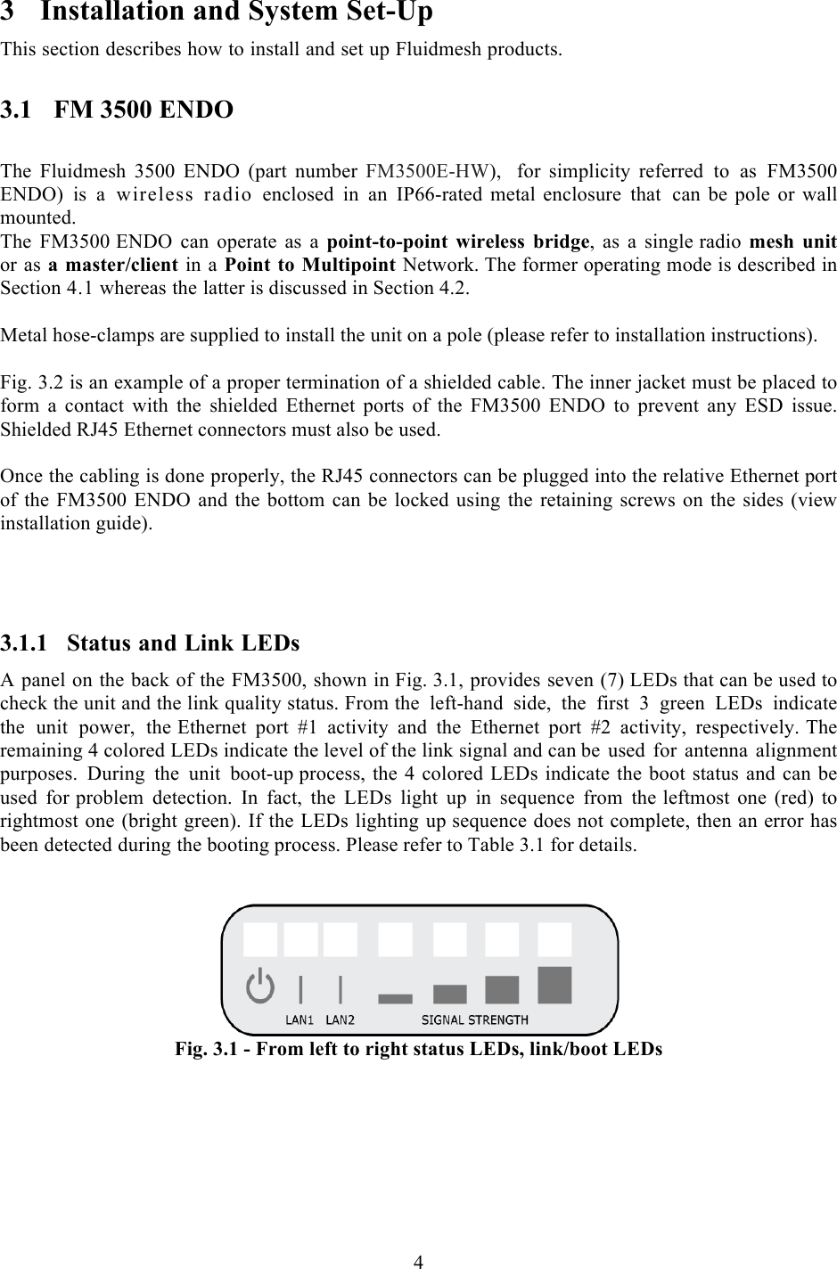
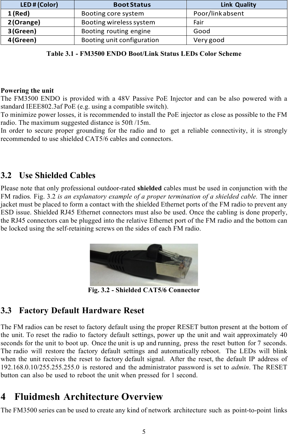
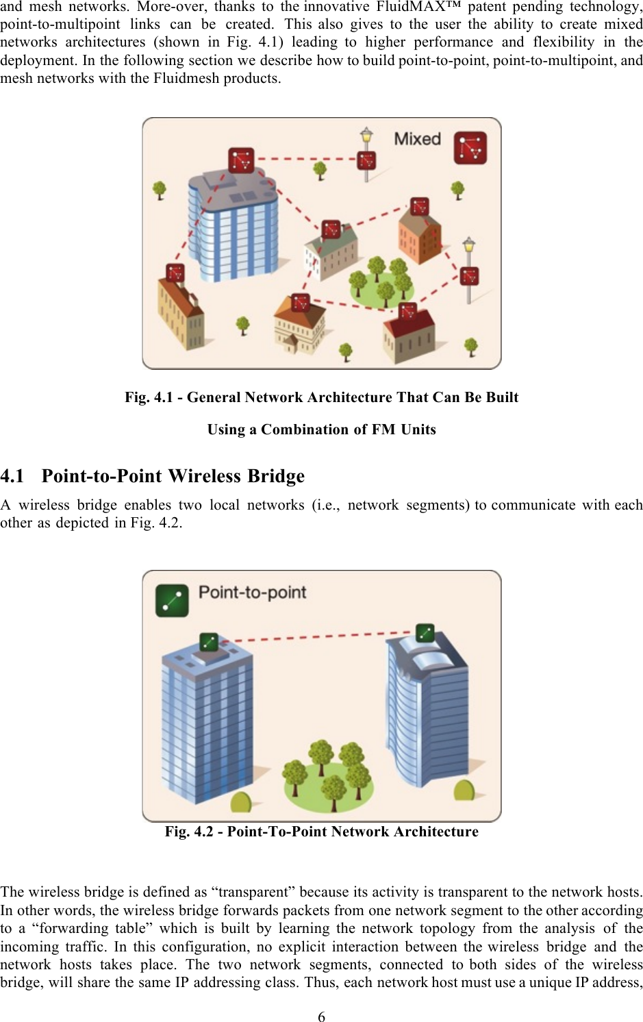
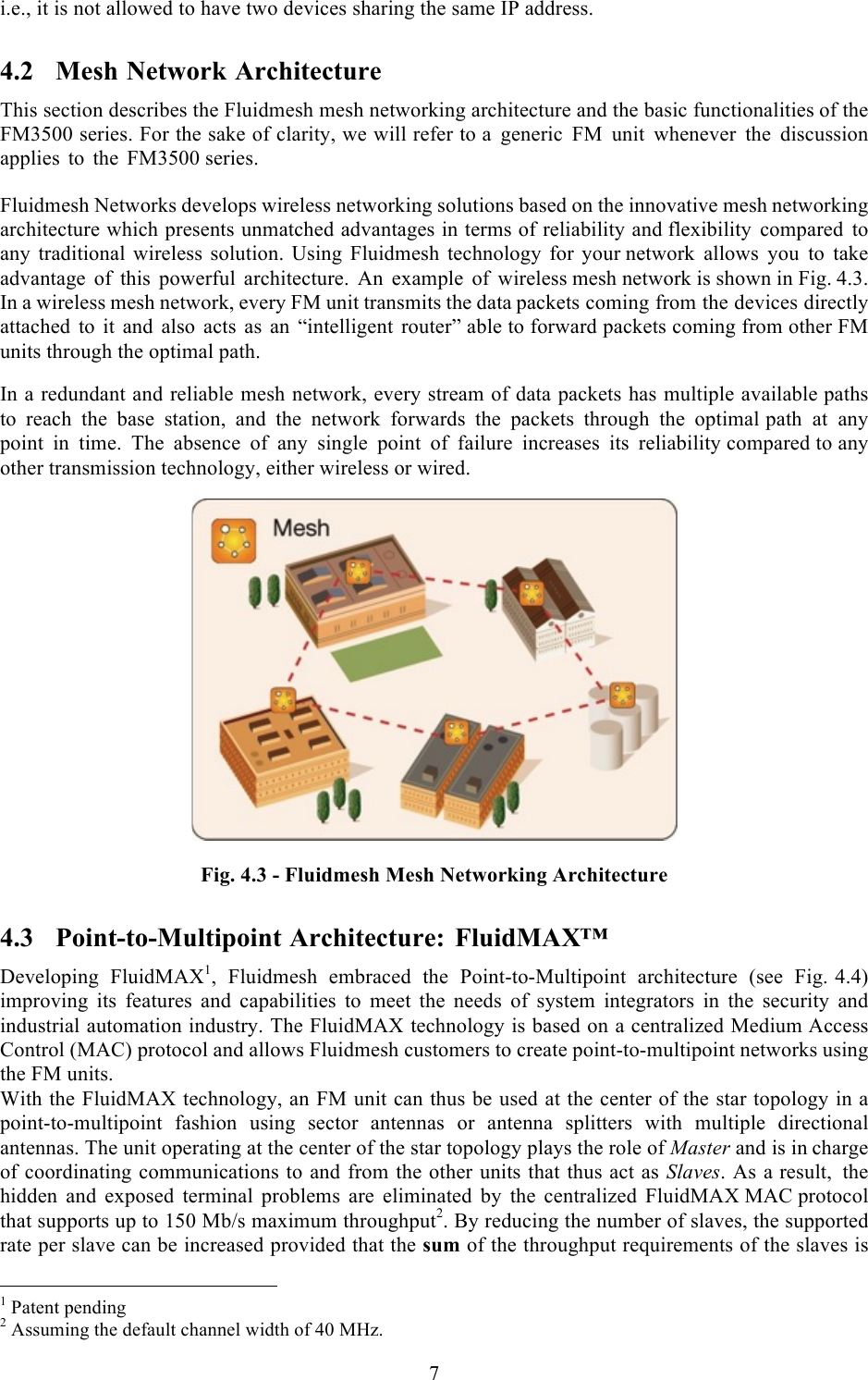
User Manual endo
Navigation menu
Upload a User Manual
Namespaces
Wiki Guide
HTML
PDF
Info
Views
User Manual
Discussion / Help
Navigation