Cisco Systems IR529WP IR529 915MHz WPAN IP67 Range Extender User Manual
Cisco Systems Inc IR529 915MHz WPAN IP67 Range Extender
UserManual.wiki
>
Cisco Systems
>
IR529WP User Manual
>
Users Manual 3
Contents
1.
Users Manual 1
2.
Users Manual 2
3.
Users Manual 3
4.
Users Manual 4
Users Manual 3
Navigation menu
Upload a User Manual
Namespaces
Wiki Guide
HTML
PDF
Info
Views
User Manual
Discussion / Help
Navigation
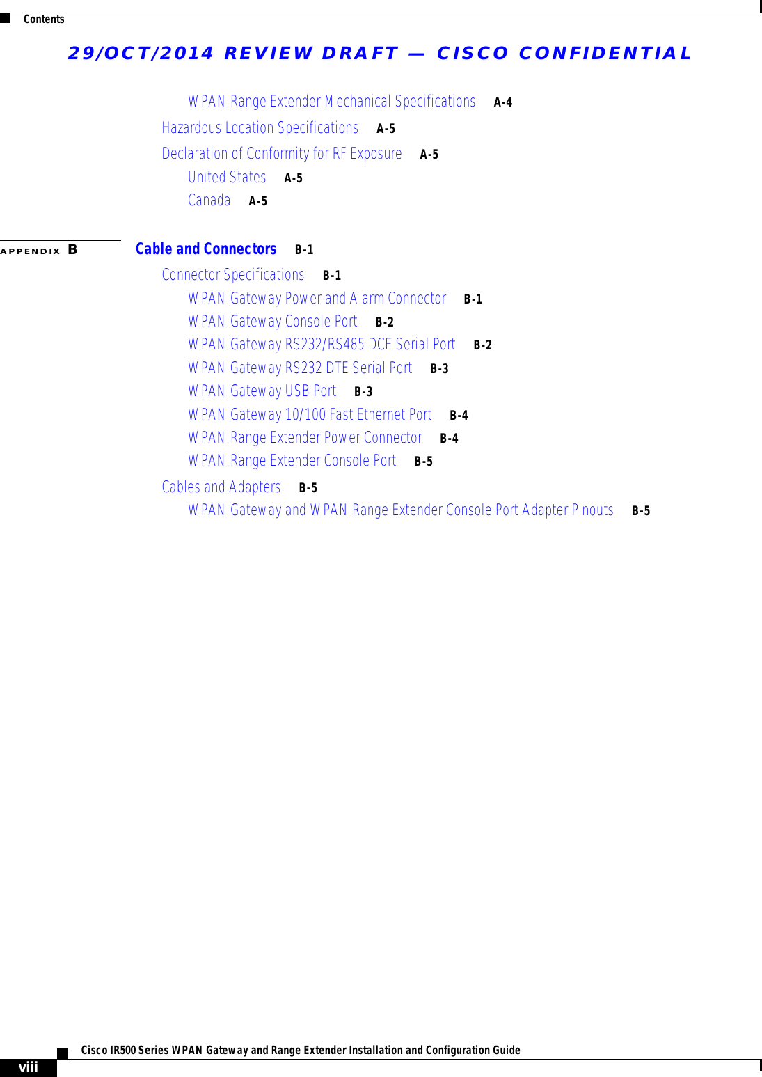
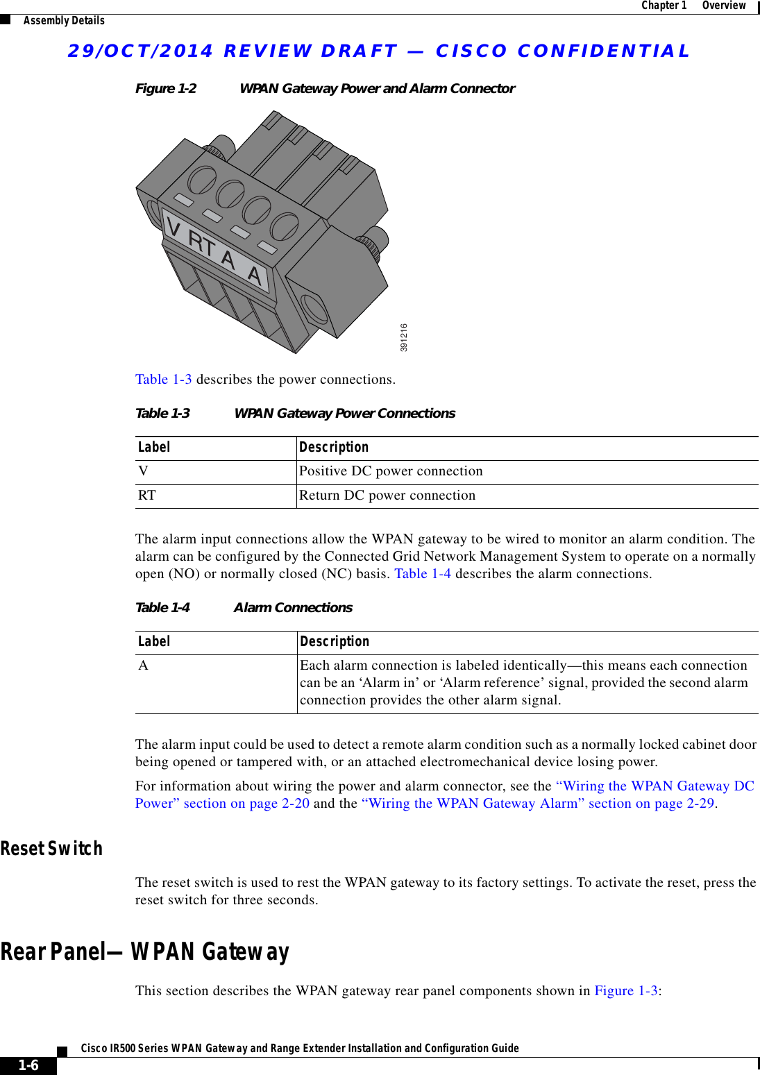
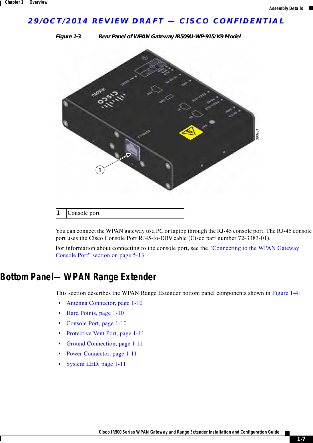
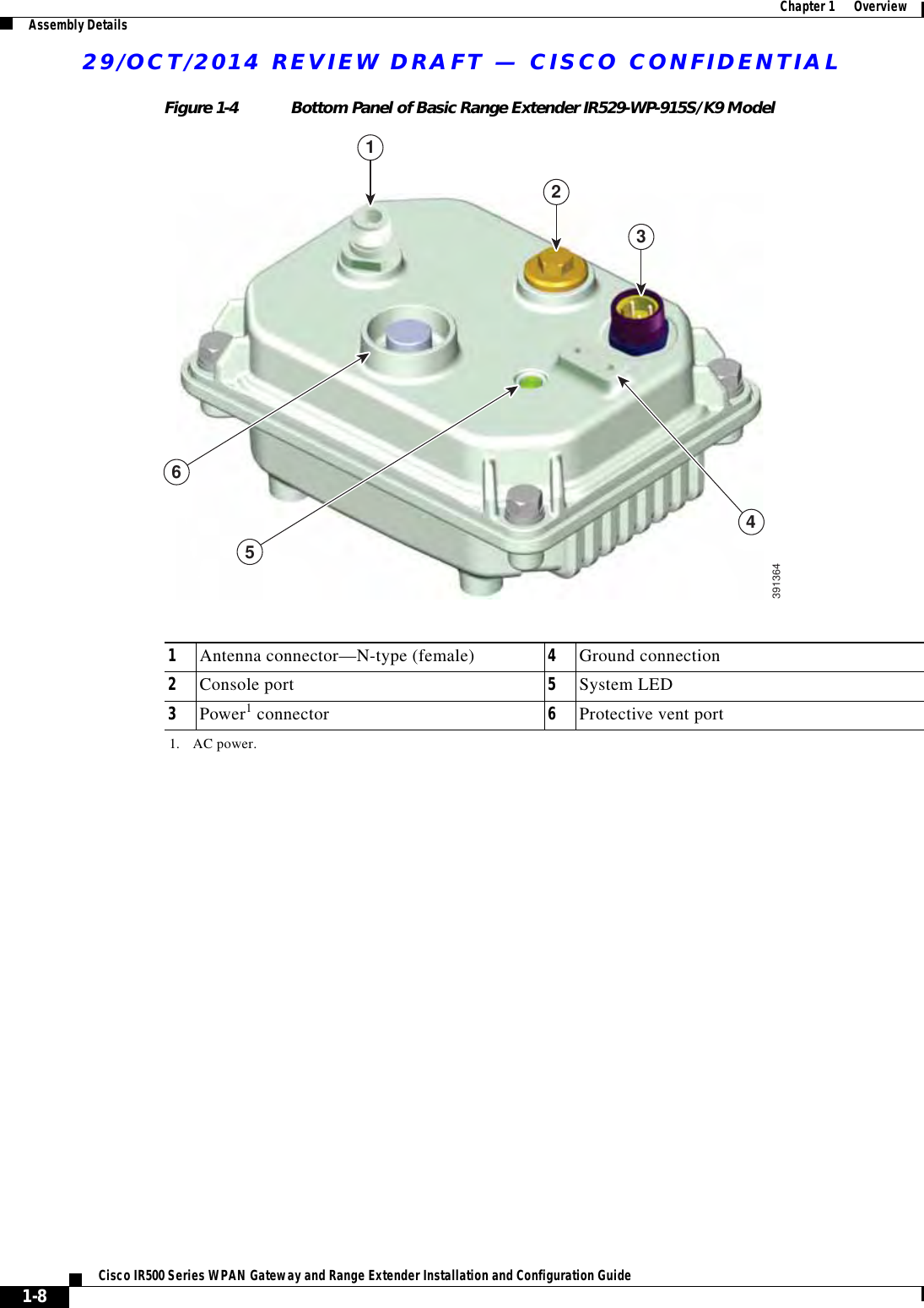
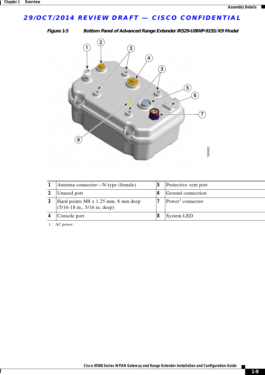
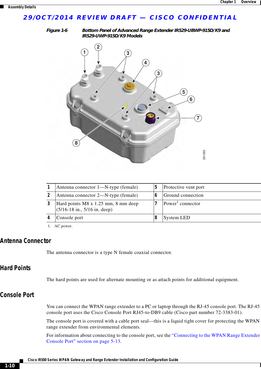
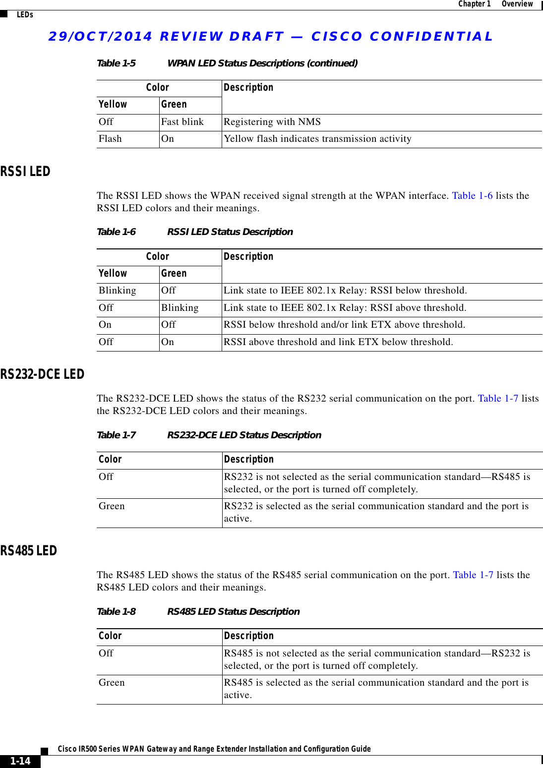
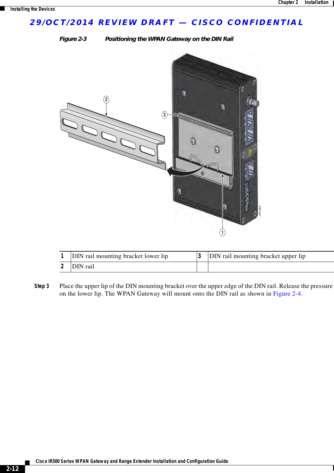
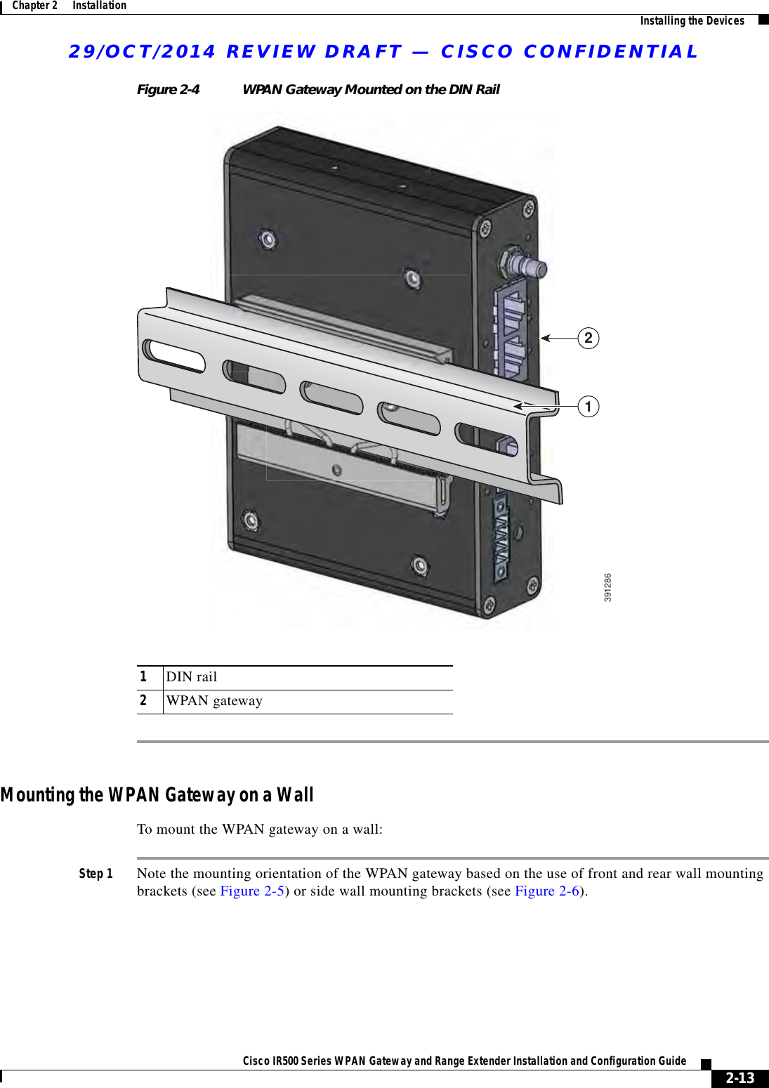
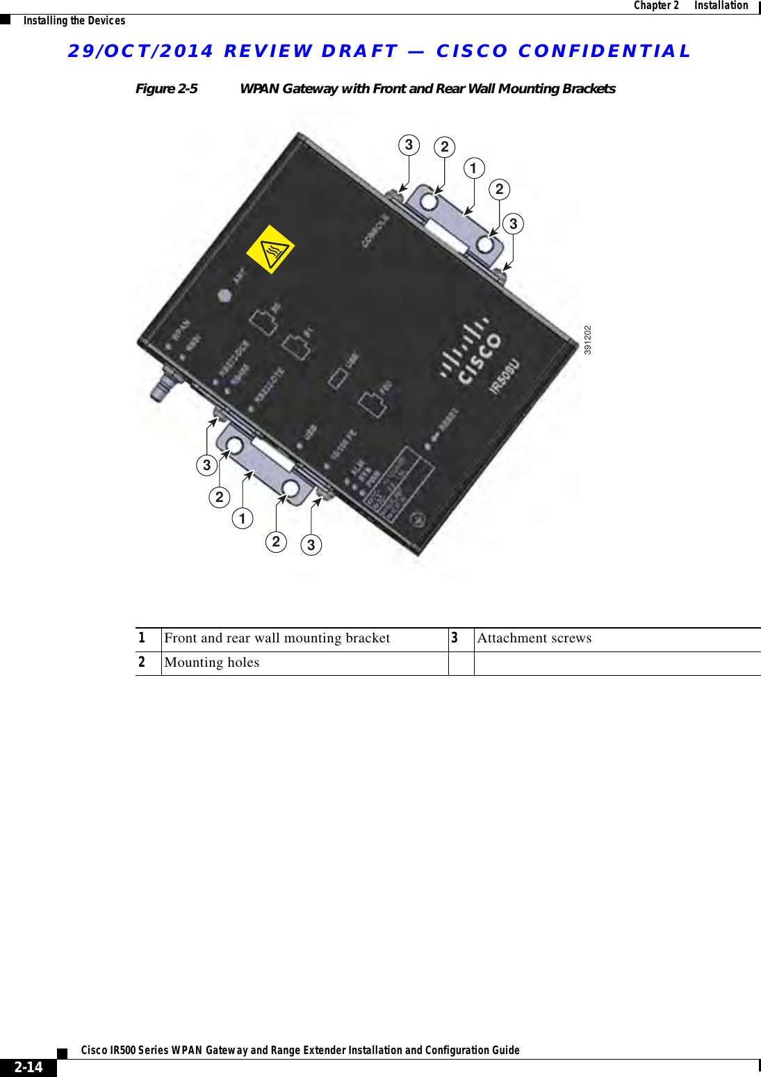
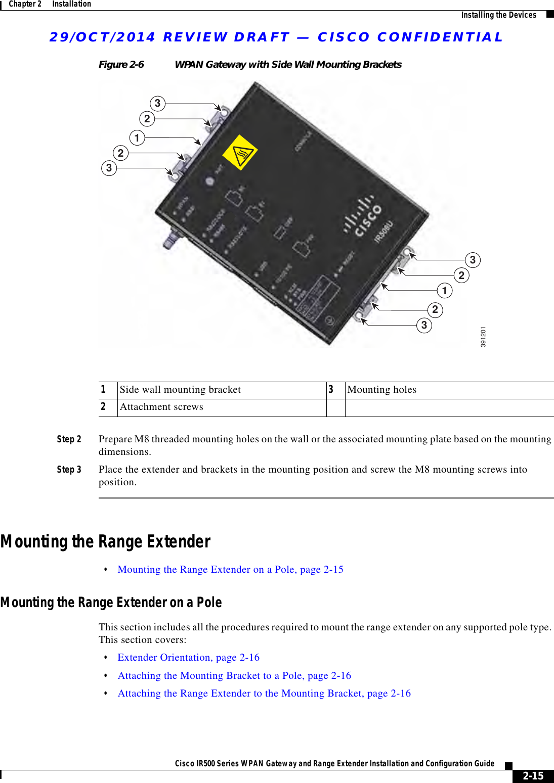
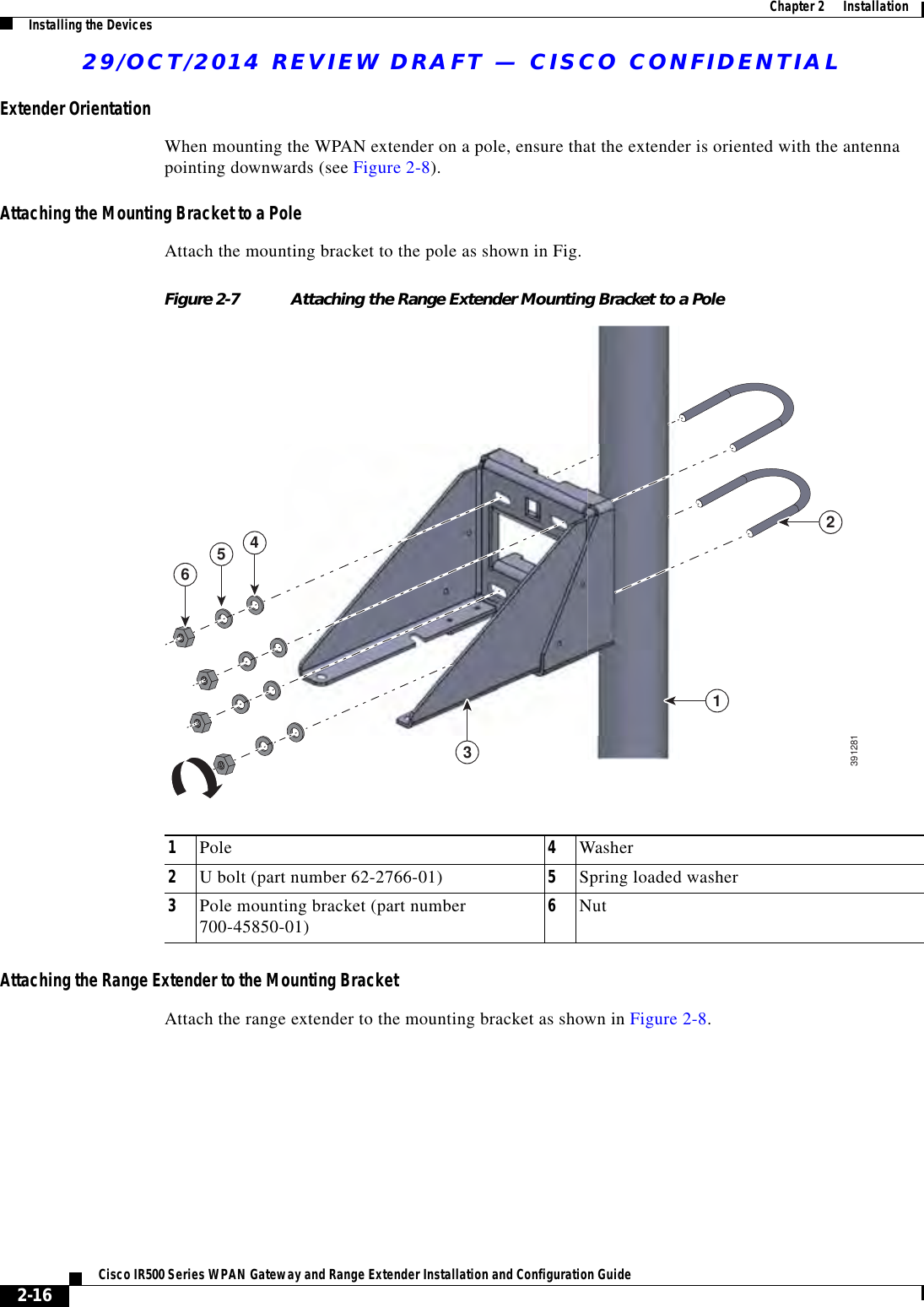
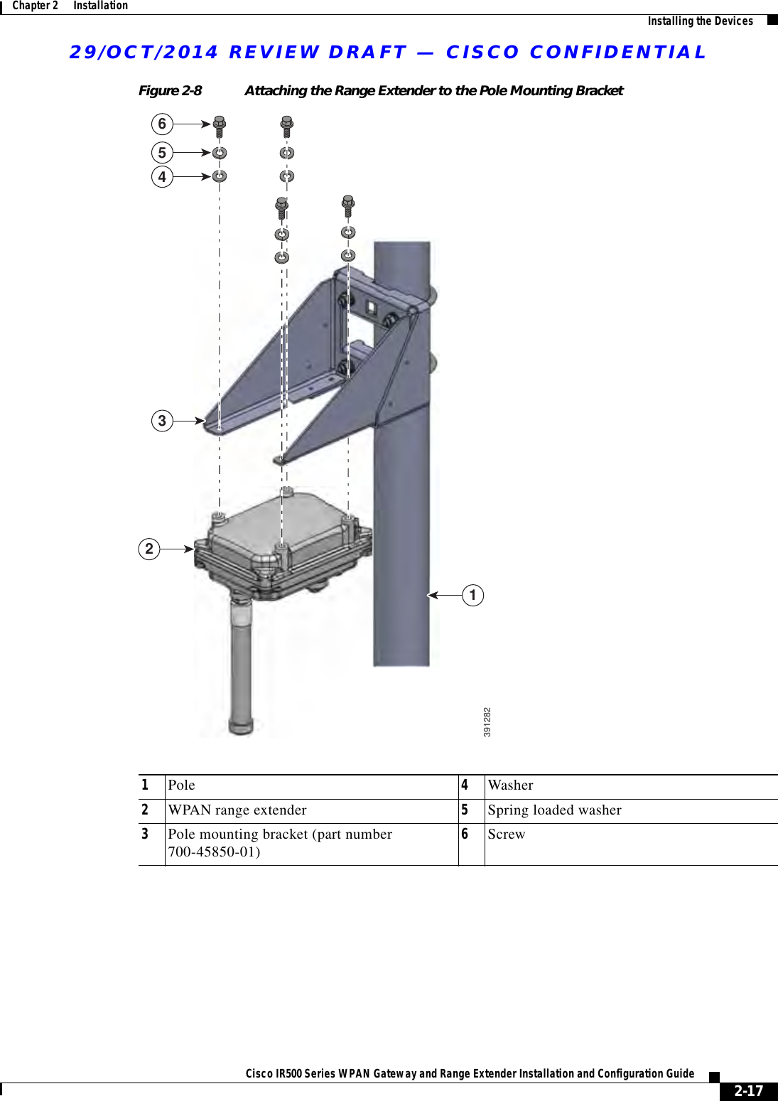
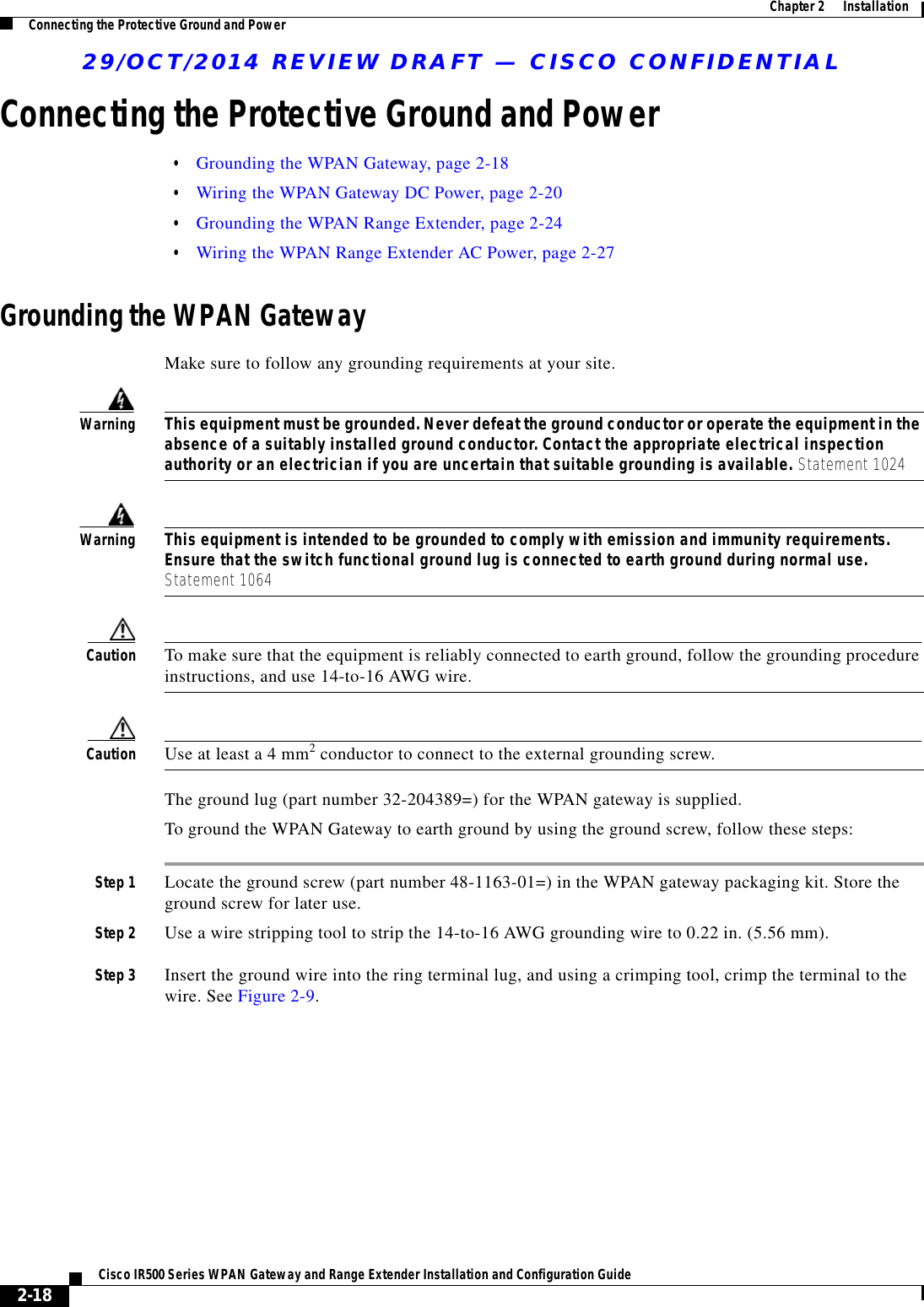
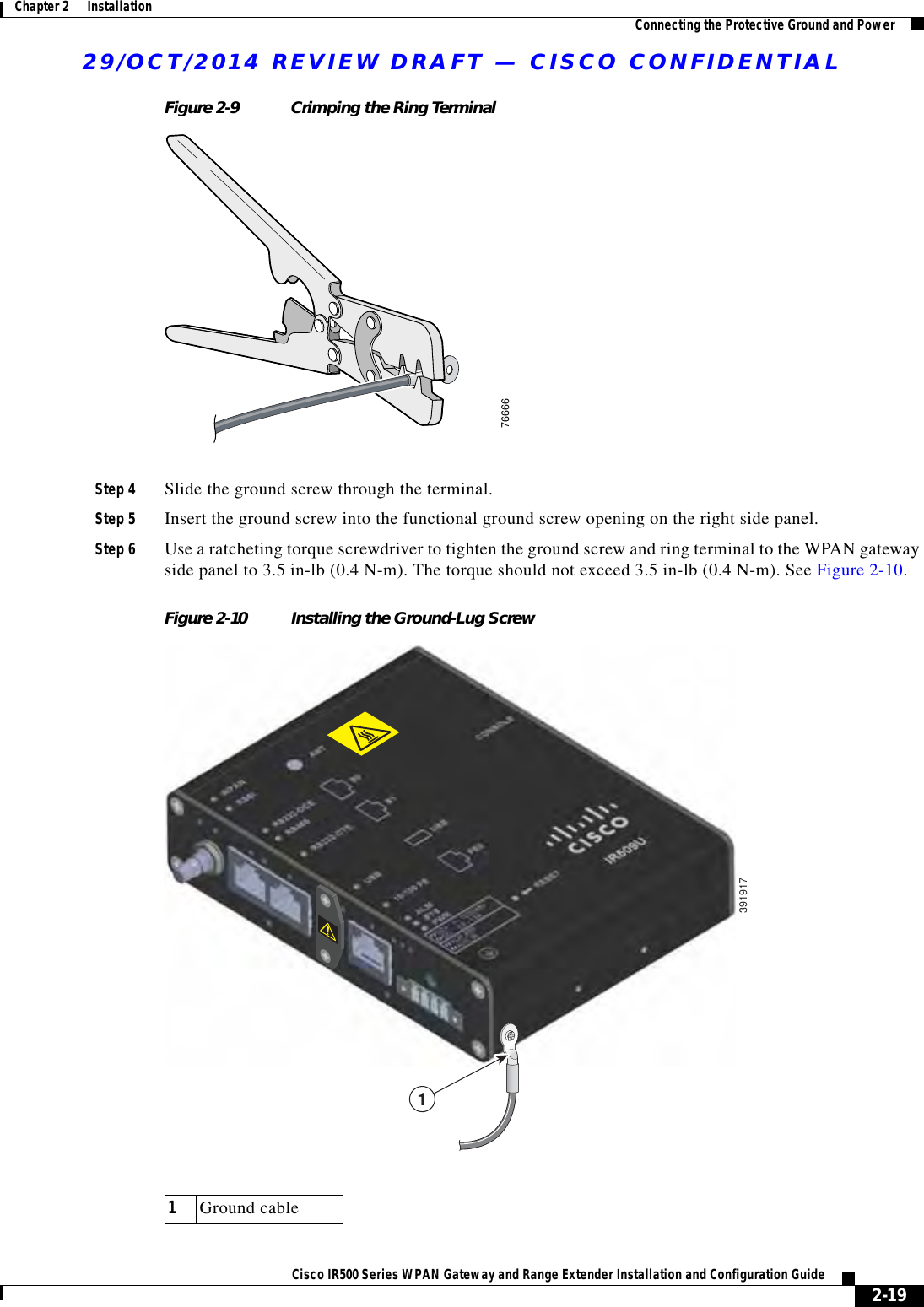
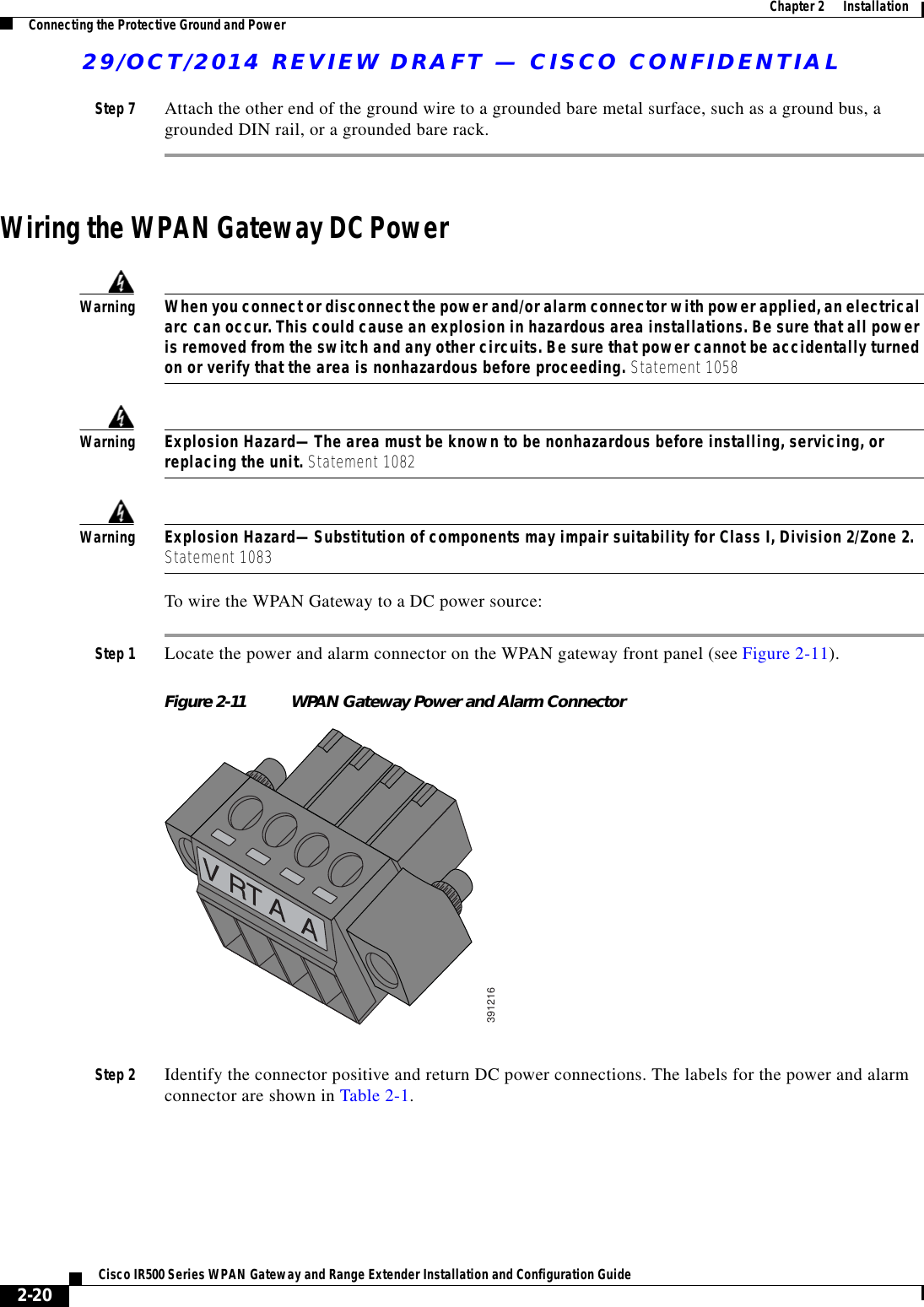
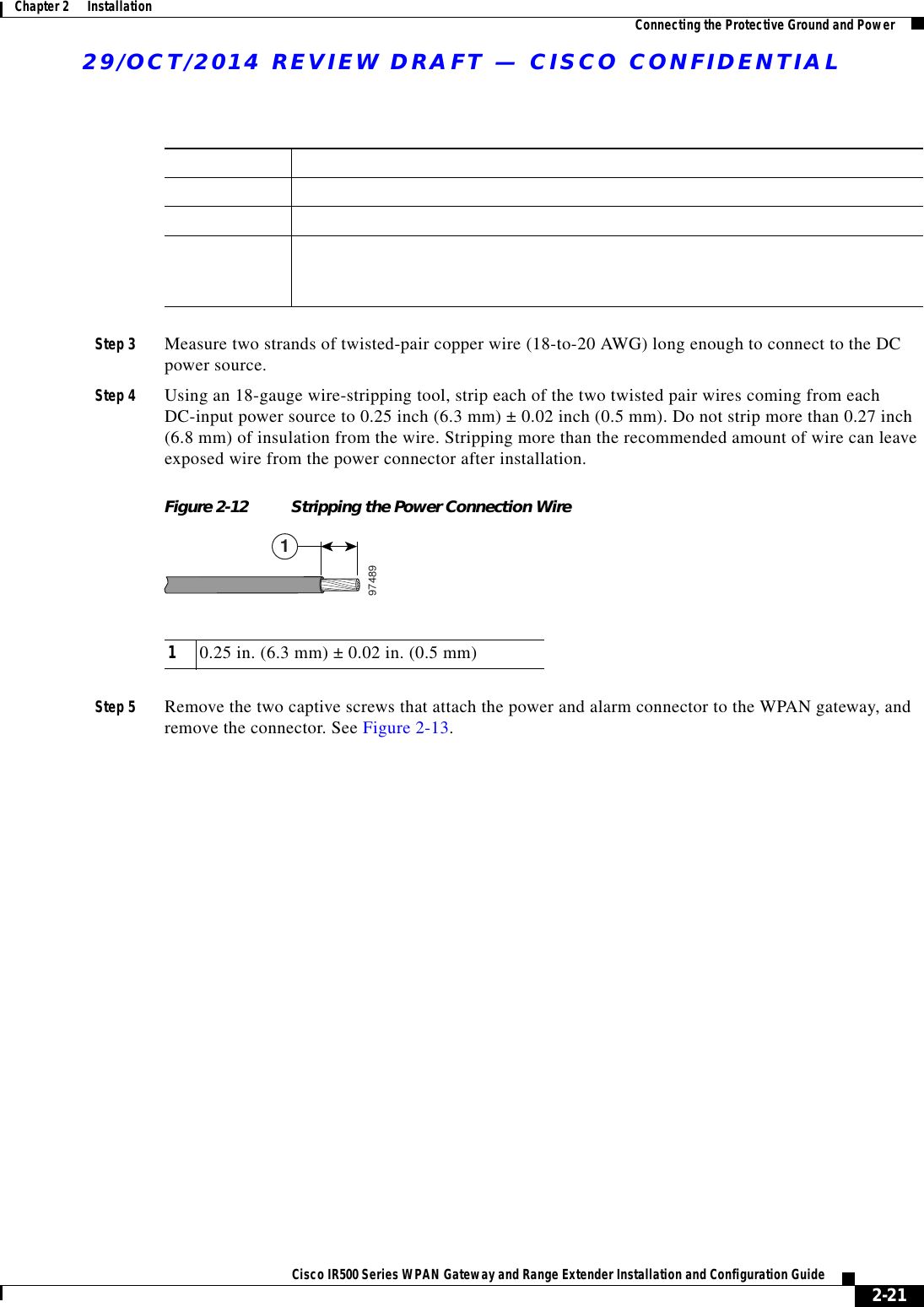
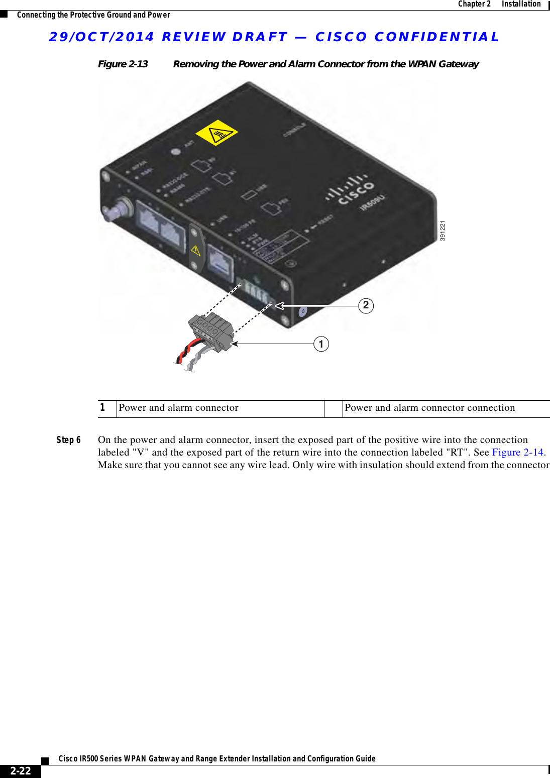
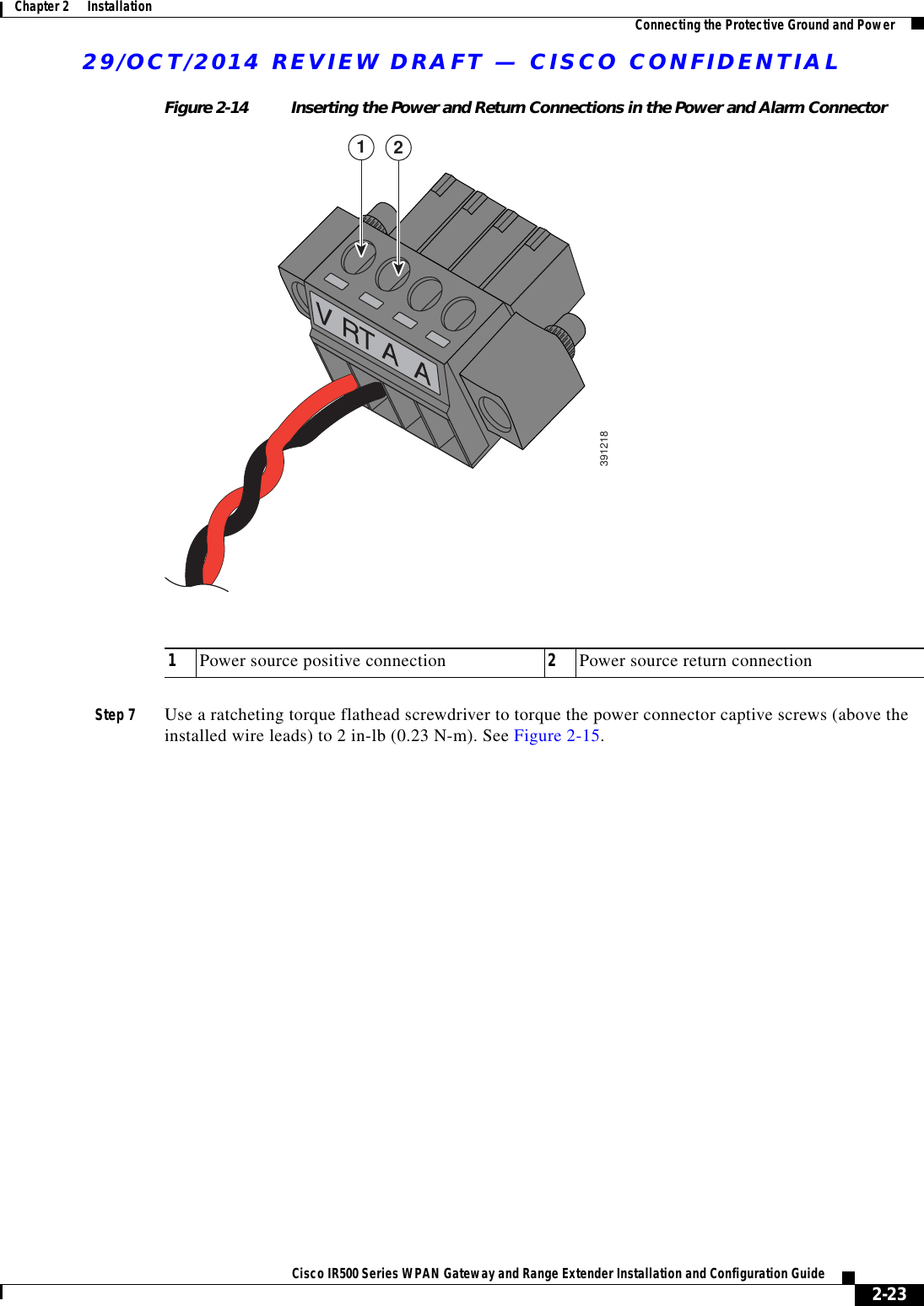
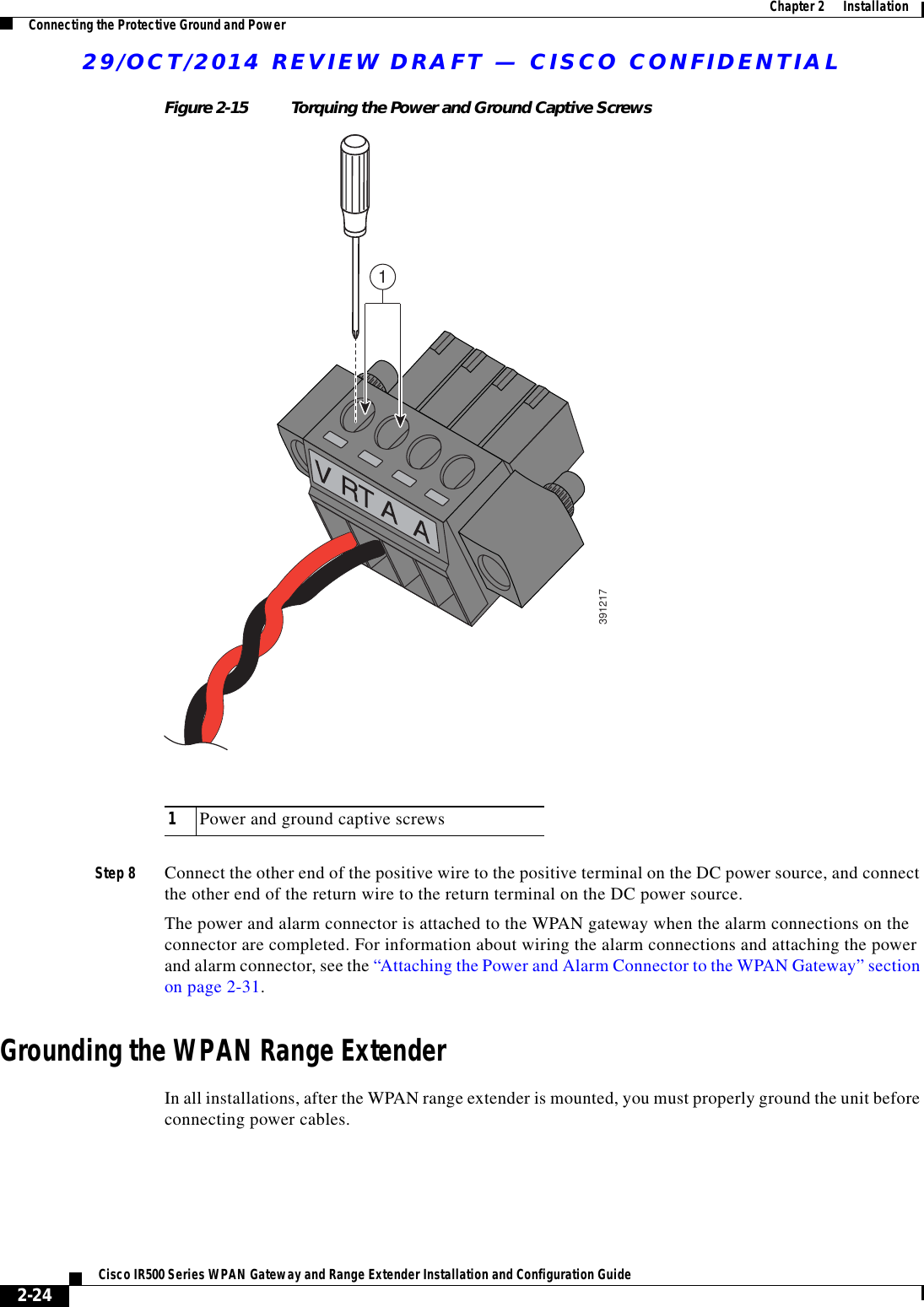
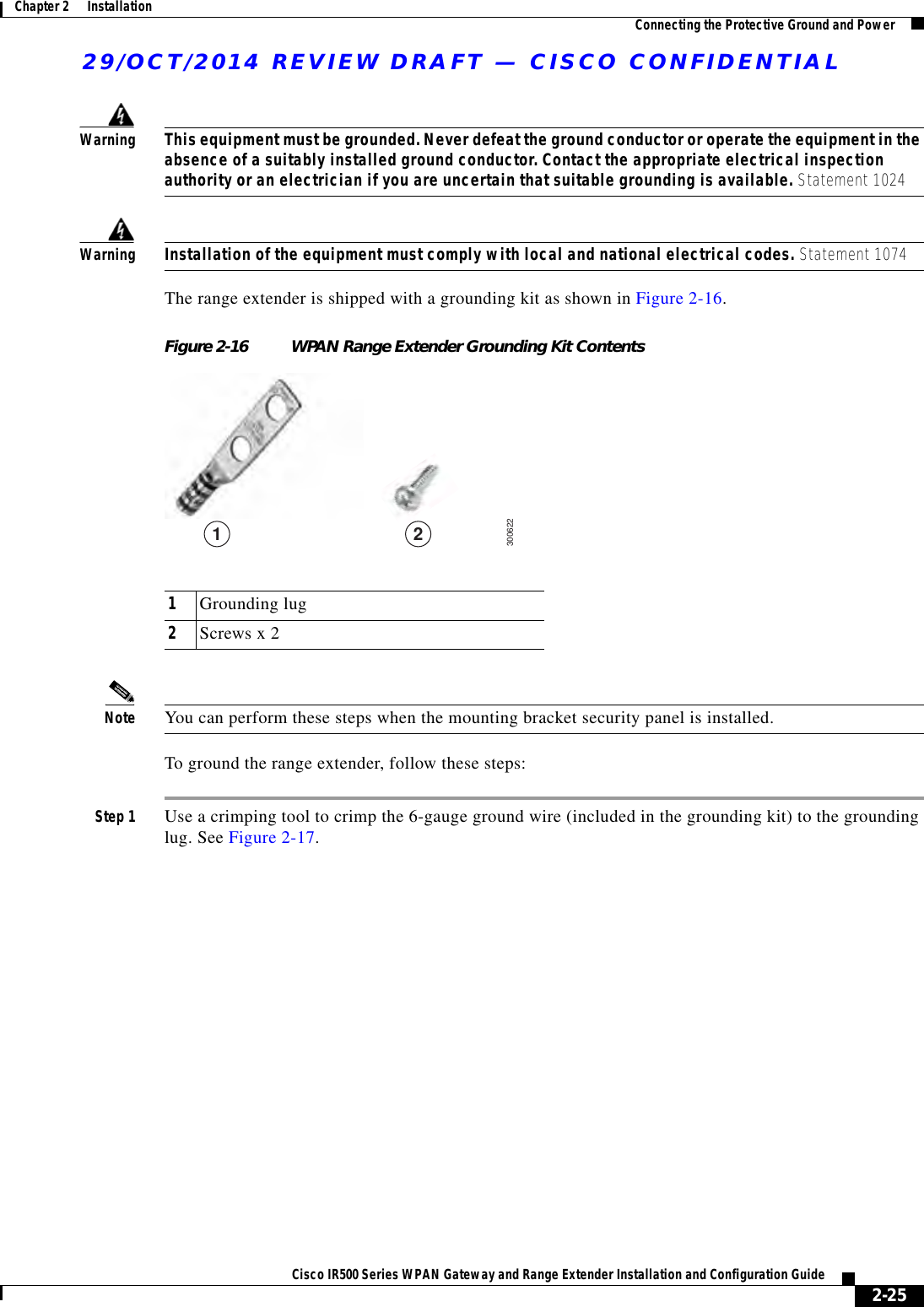
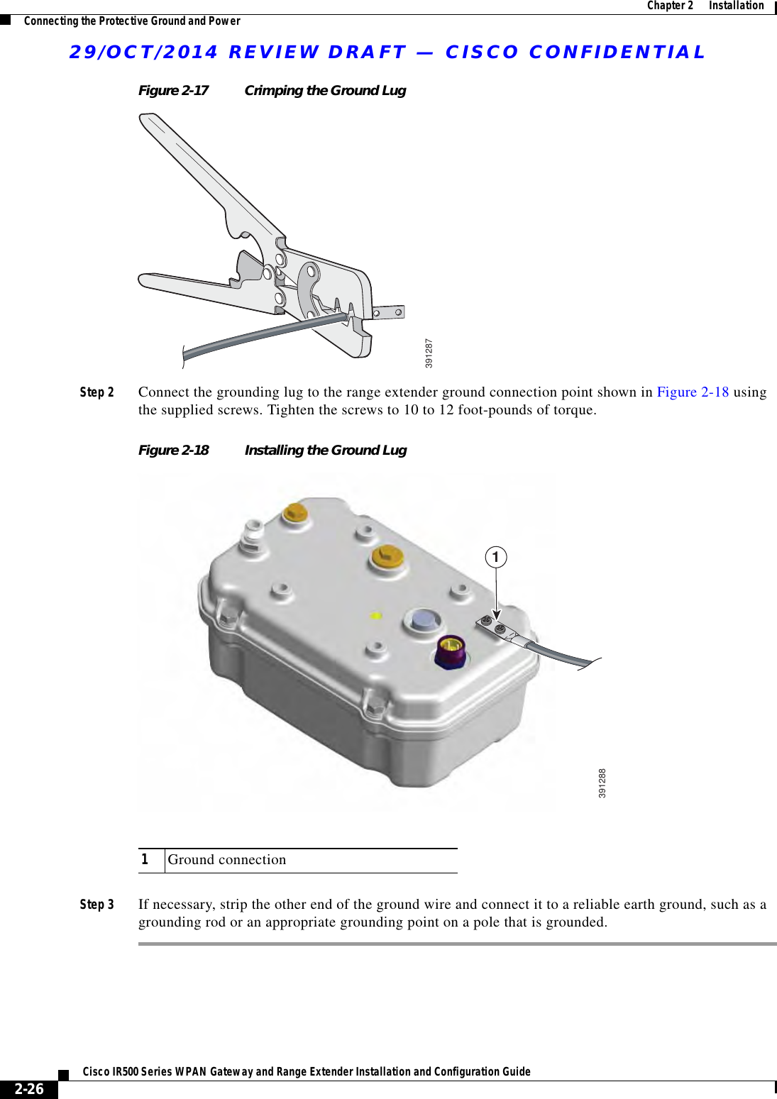
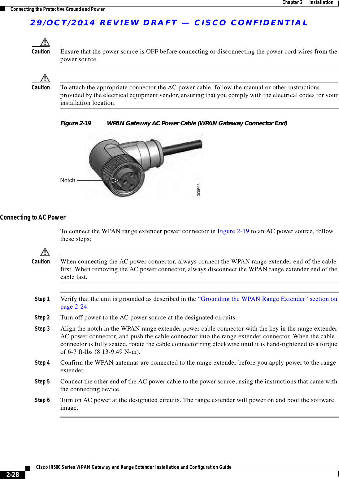
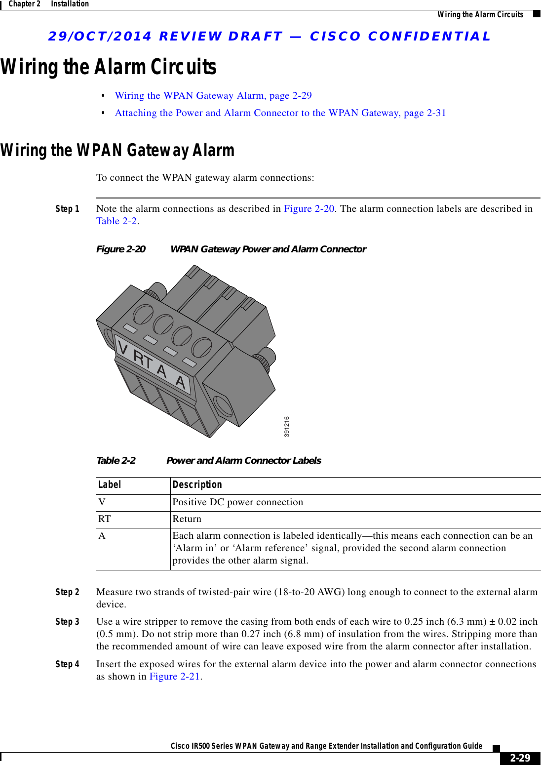
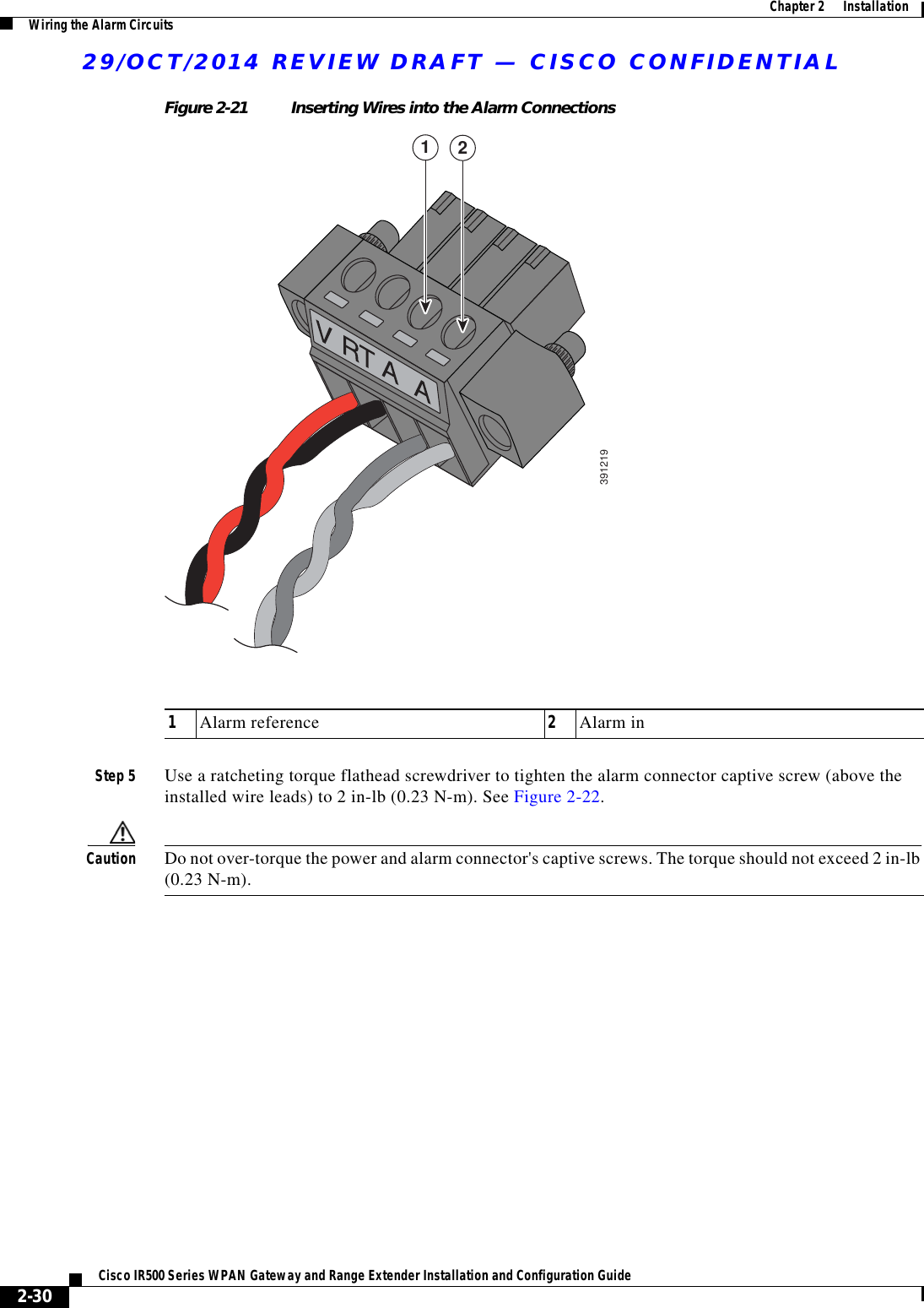
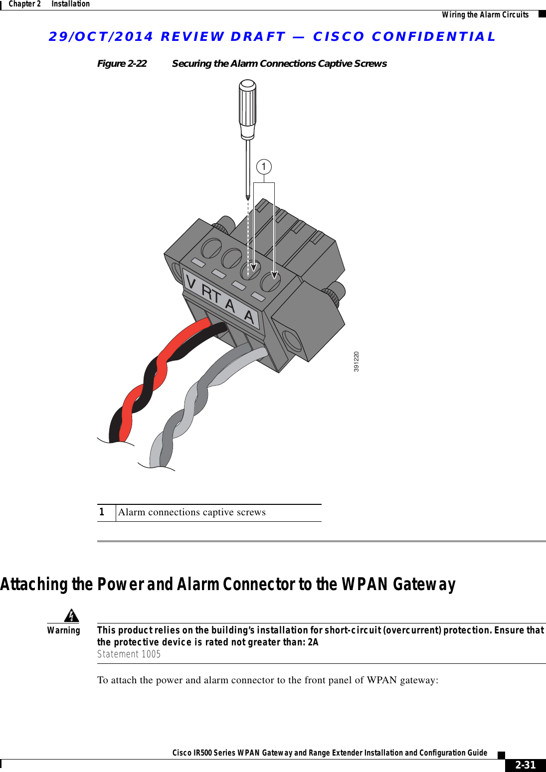
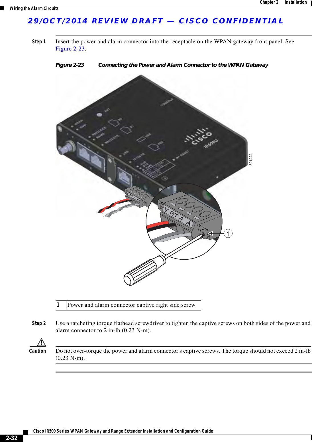
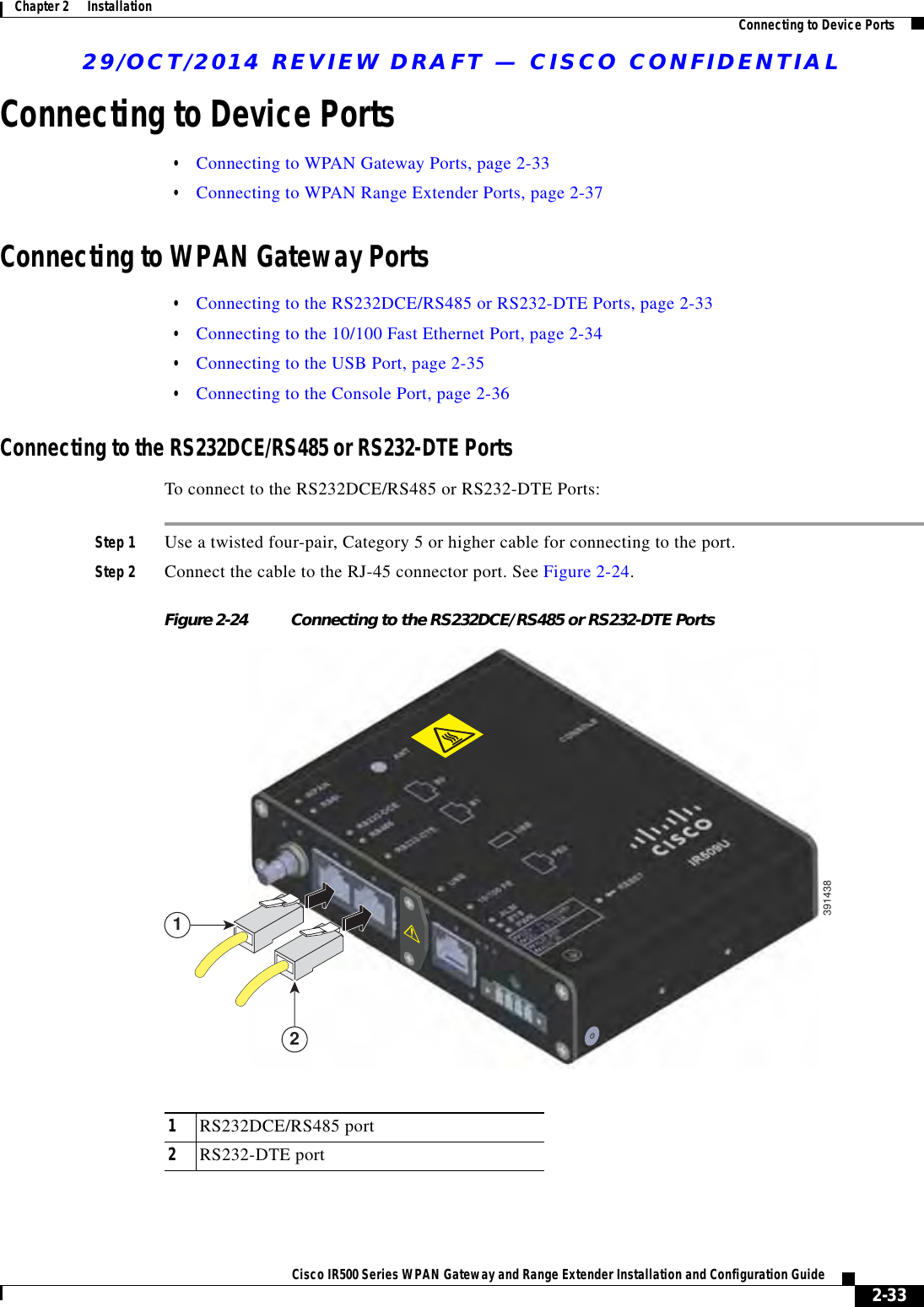
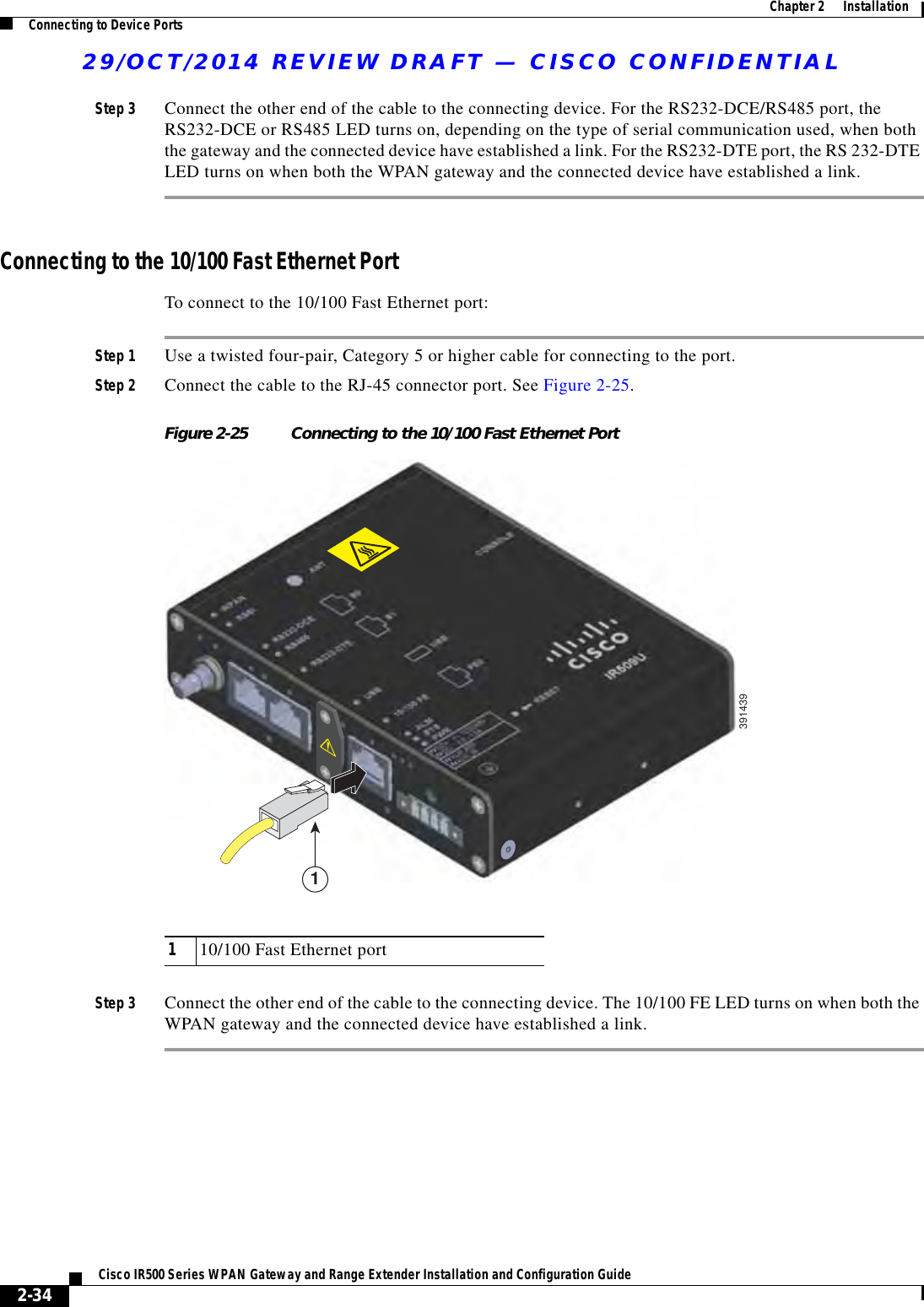
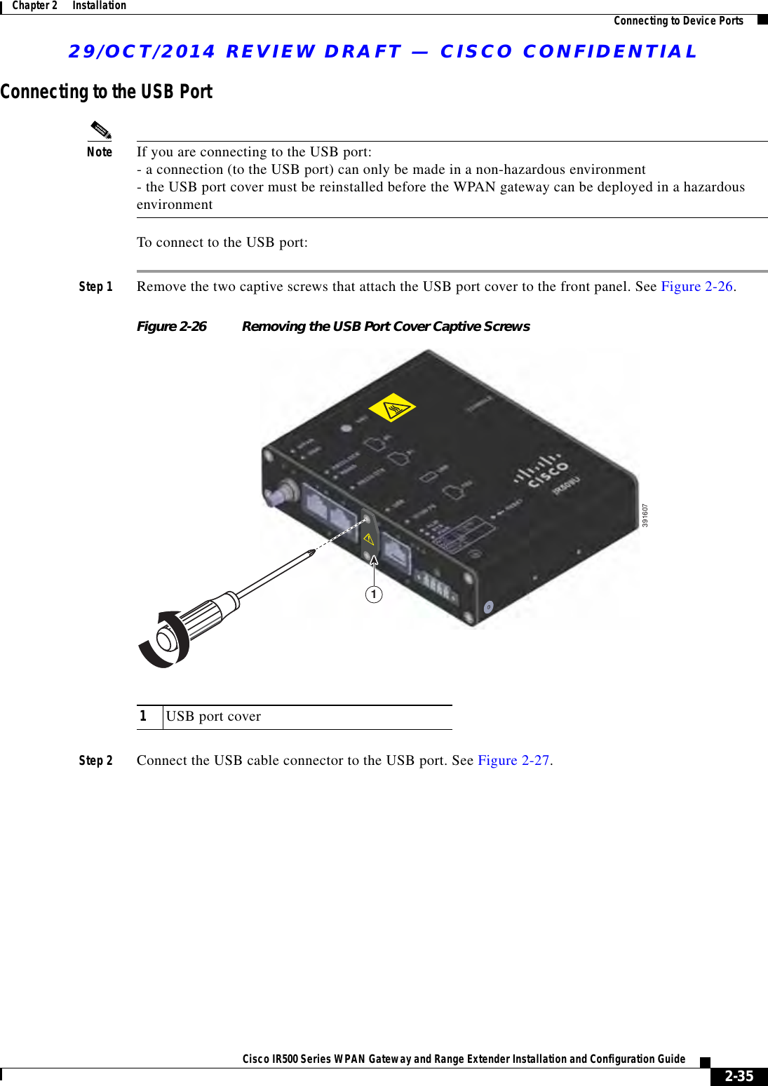
![29/OCT/2014 REVIEW DRAFT — CISCO CONFIDENTIALixCisco IR500 Series WPAN Gateway and Range Extender Installation and Configuration Guide PrefaceAudienceThis guide is for the networking or computer technician responsible for installing and configuring WPAN gateway and WPAN range extender devices.ConventionsThis document uses the following conventions: Convention Indicationbold font Commands and keywords and user-entered text appear in bold font.italic font Document titles, new or emphasized terms, and arguments for which you supply values are in italic font.[ ] Elements in square brackets are optional.{x | y | z } Required alternative keywords are grouped in braces and separated by vertical bars.[ x | y | z ] Optional alternative keywords are grouped in brackets and separated by vertical bars.string A nonquoted set of characters. Do not use quotation marks around the string or the string will include the quotation marks.courier font Terminal sessions and information the system displays appear in courier font.< > Nonprinting characters such as passwords are in angle brackets.[ ] Default responses to system prompts are in square brackets.!, # An exclamation point (!) or a pound sign (#) at the beginning of a line of code indicates a comment line.Note Means reader take note. Notes contain helpful suggestions or references to material not covered in the manual.](https://usermanual.wiki/Cisco-Systems/IR529WP.Users-Manual-3/User-Guide-2532999-Page-9.png)