Cisco Systems ISM-BTS-R1 Ripwave TTA Base Station User Manual ttaicguide
Cisco Systems, Inc Ripwave TTA Base Station ttaicguide
UserManual.wiki
>
Cisco Systems
>
ISM-BTS-R1 User Manual
>
Users Manual Section2
Contents
1.
Users manual
2.
Users Manual Section1
3.
Users Manual Section2
Users Manual Section2
Navigation menu
Upload a User Manual
Namespaces
Wiki Guide
HTML
PDF
Info
Views
User Manual
Discussion / Help
Navigation
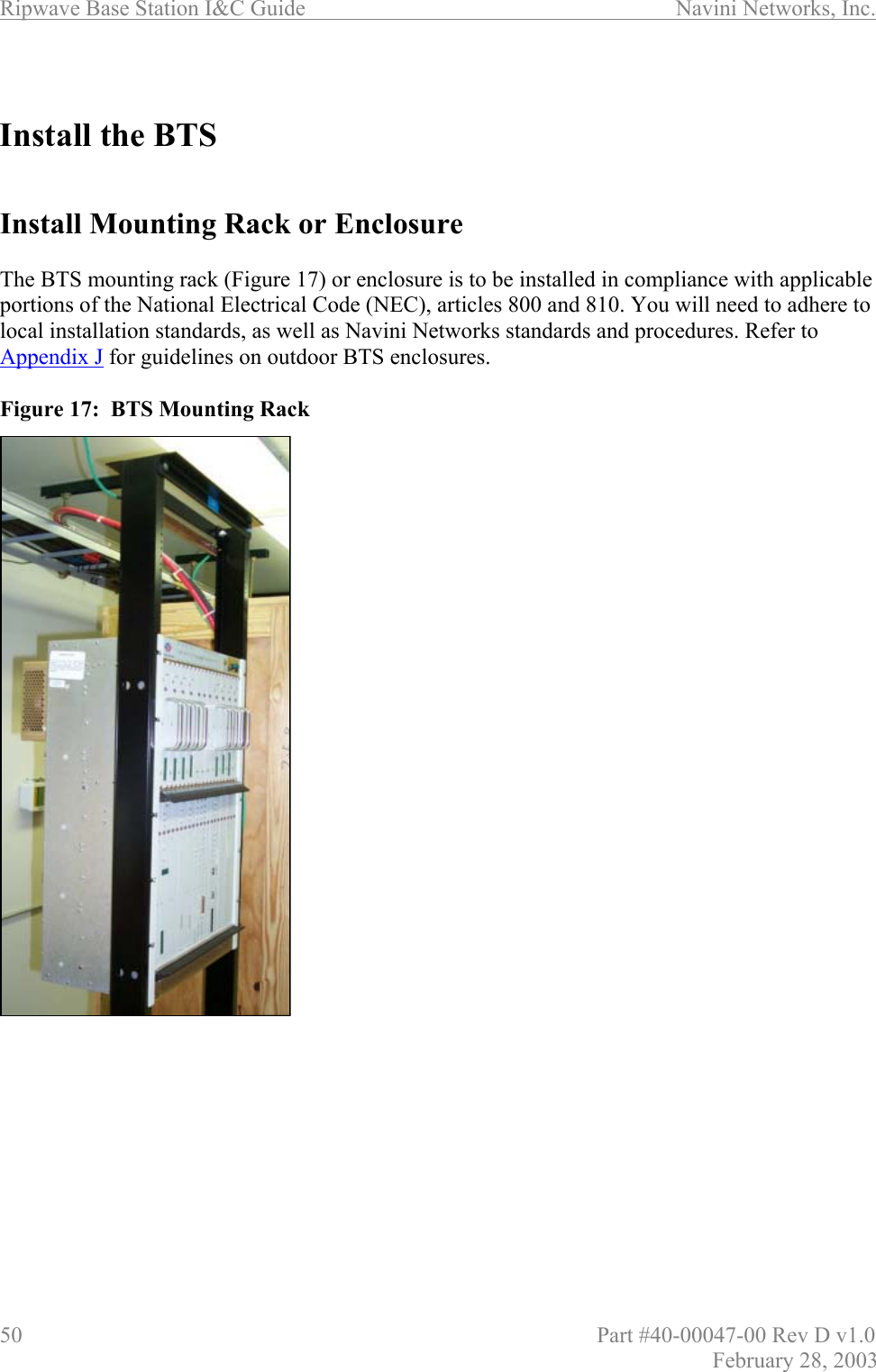
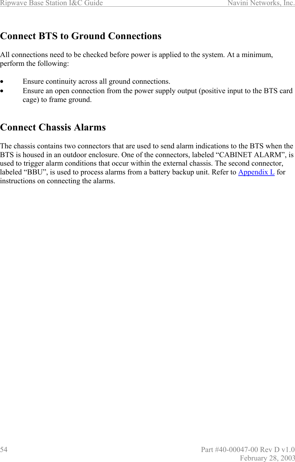
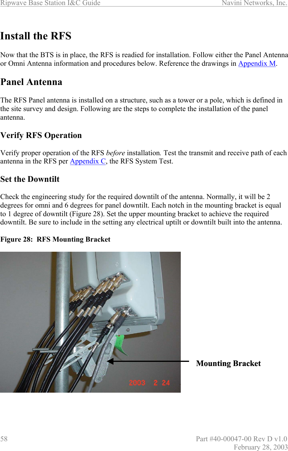

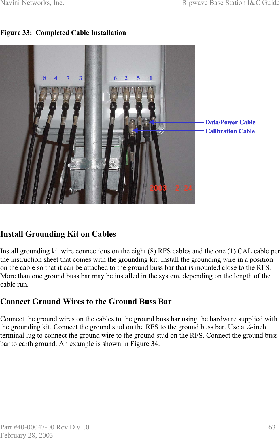
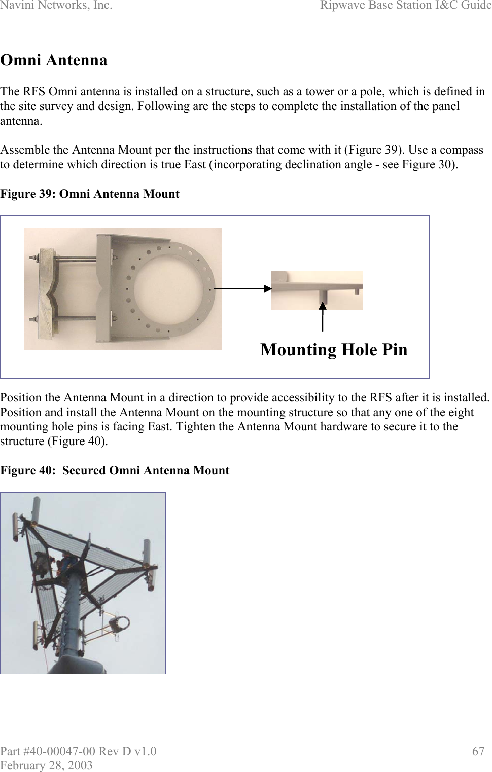
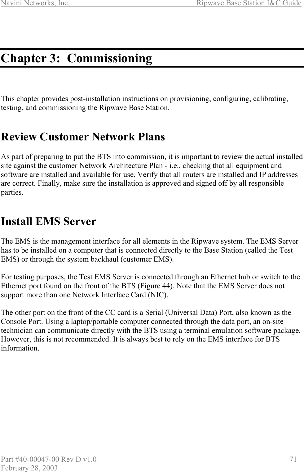

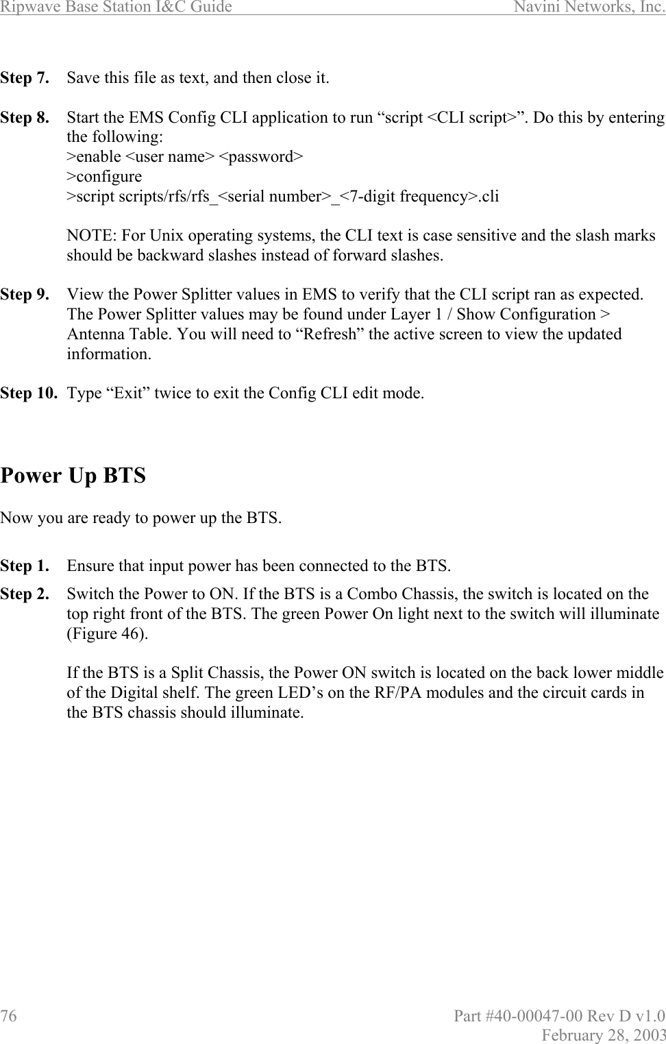
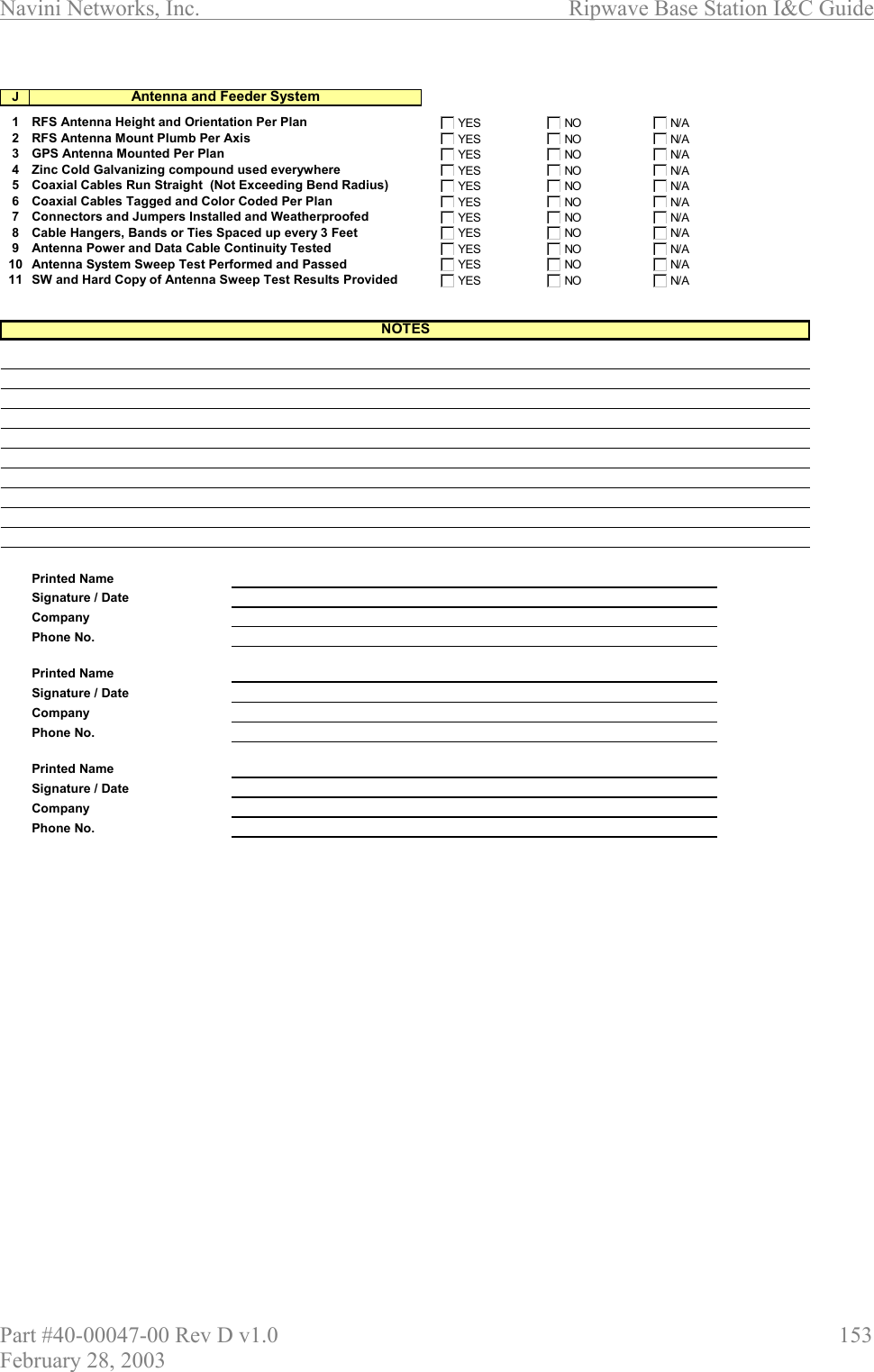
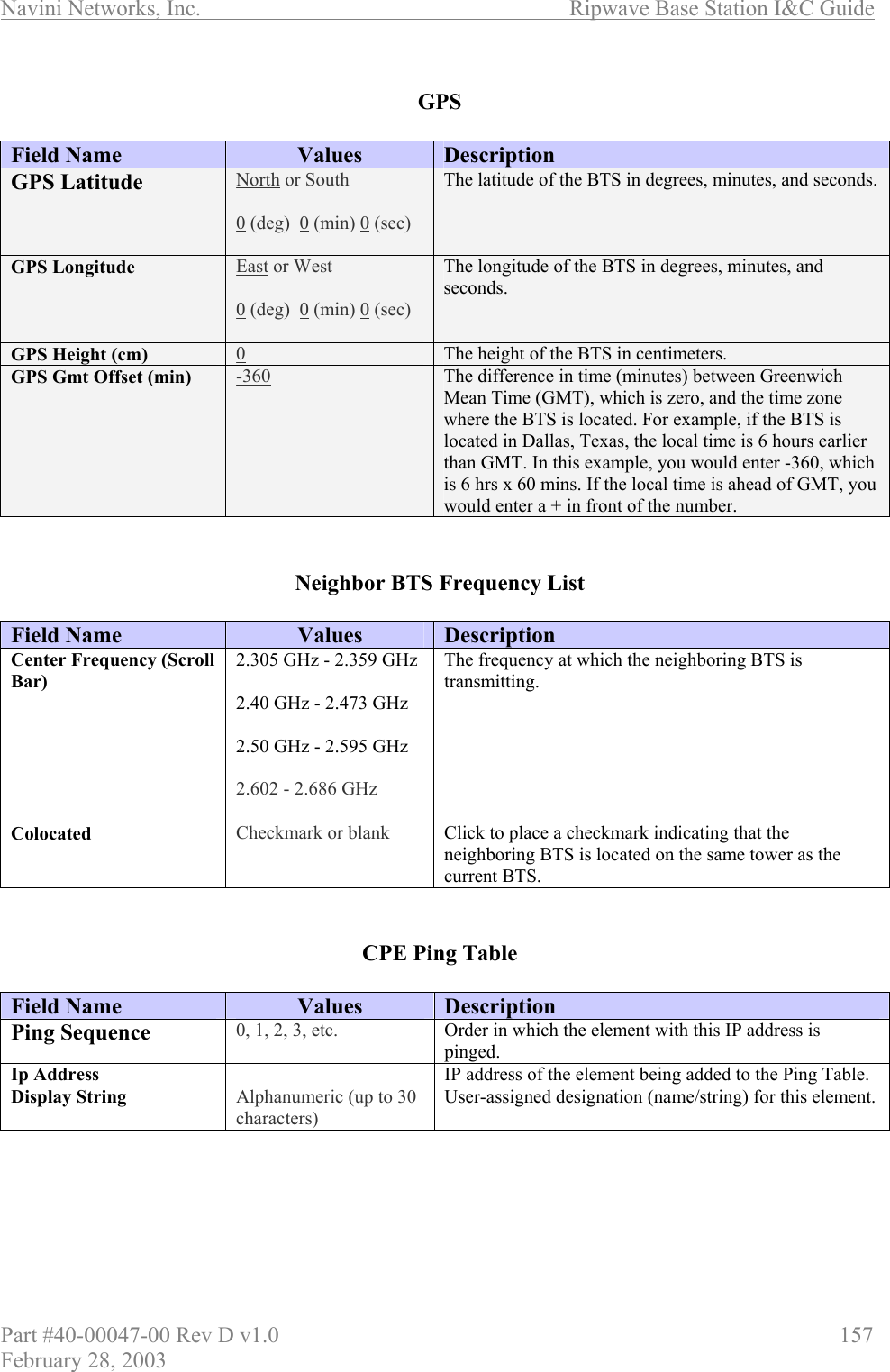
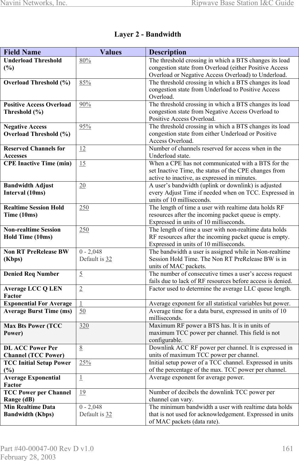
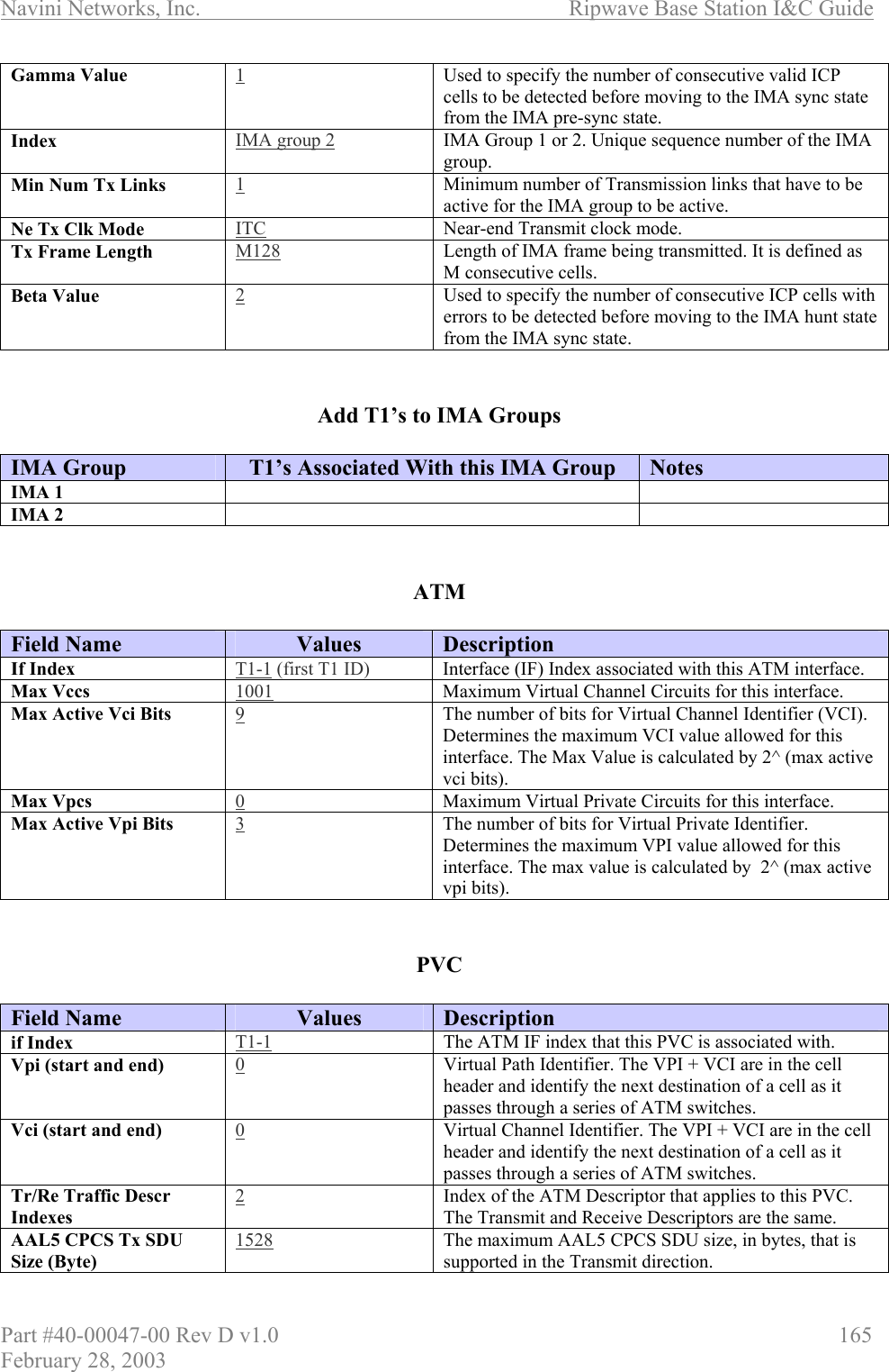
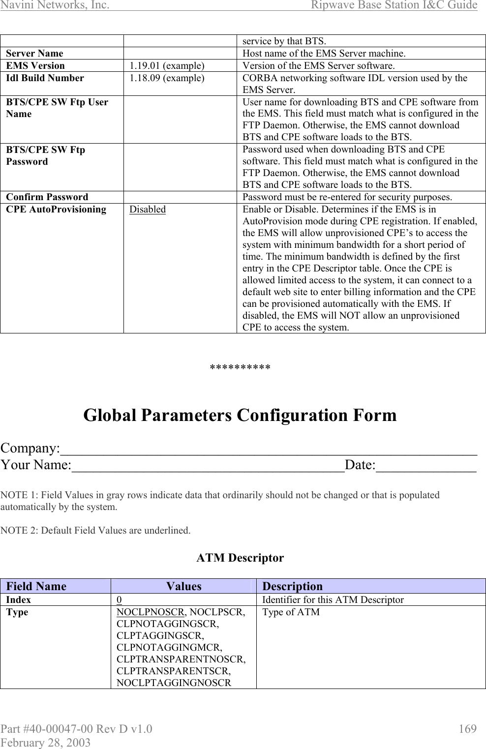
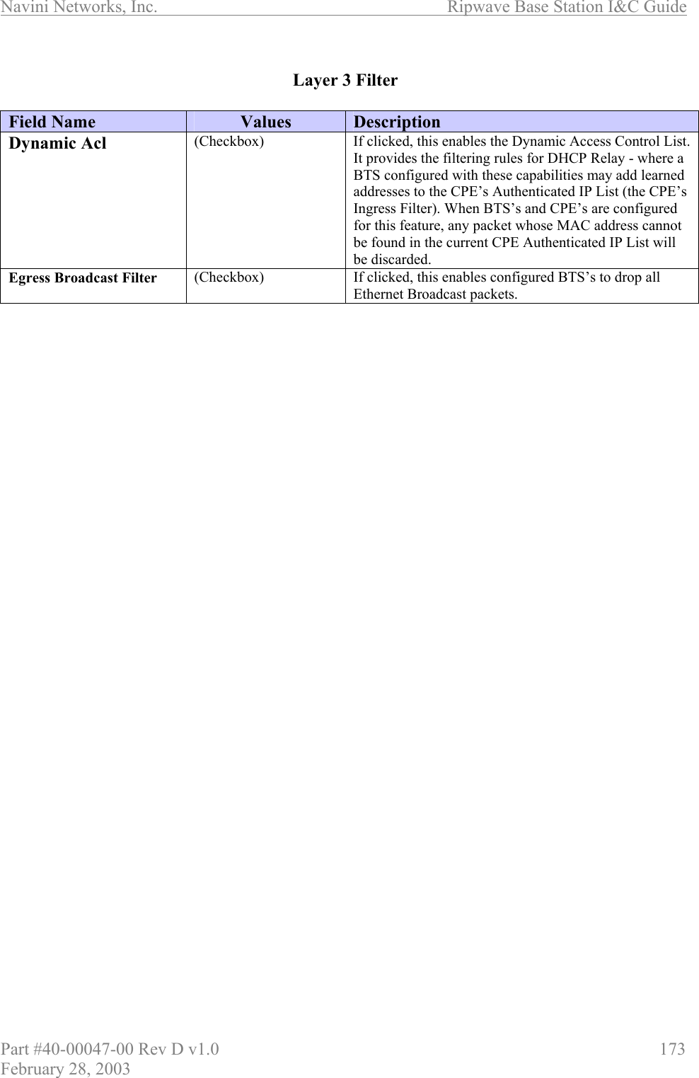
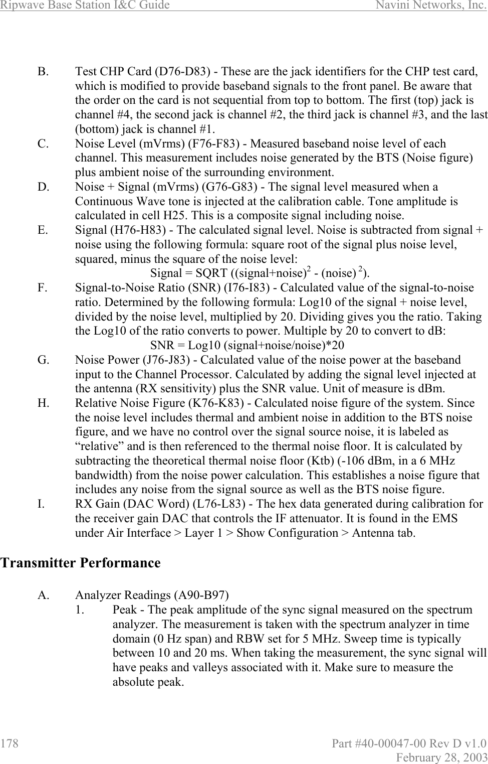
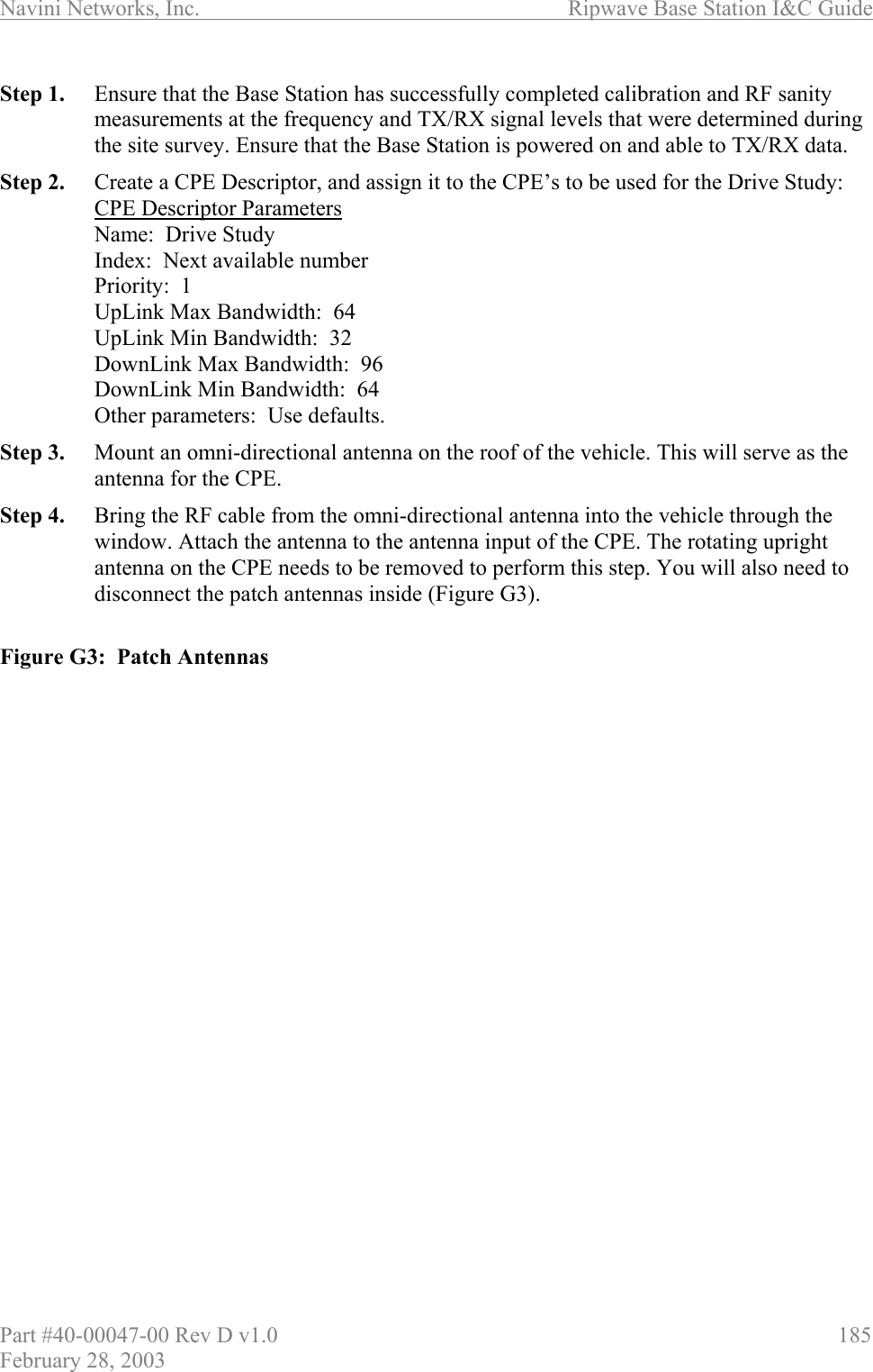
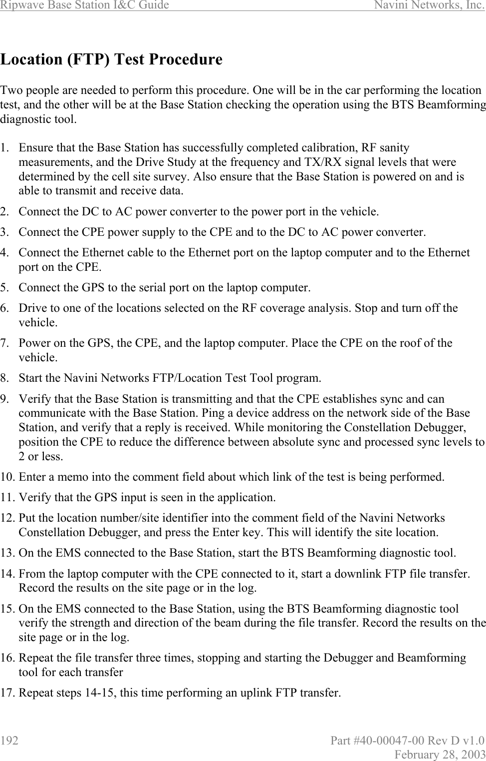
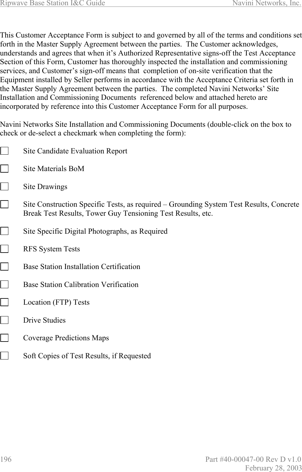
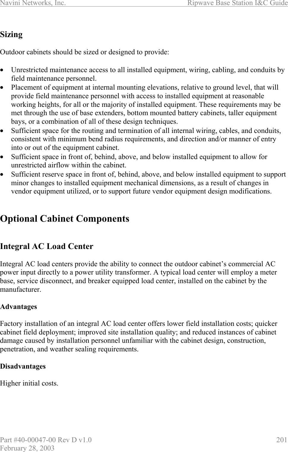
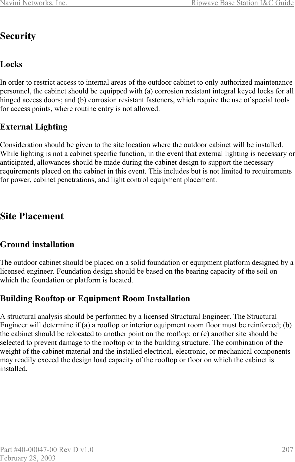
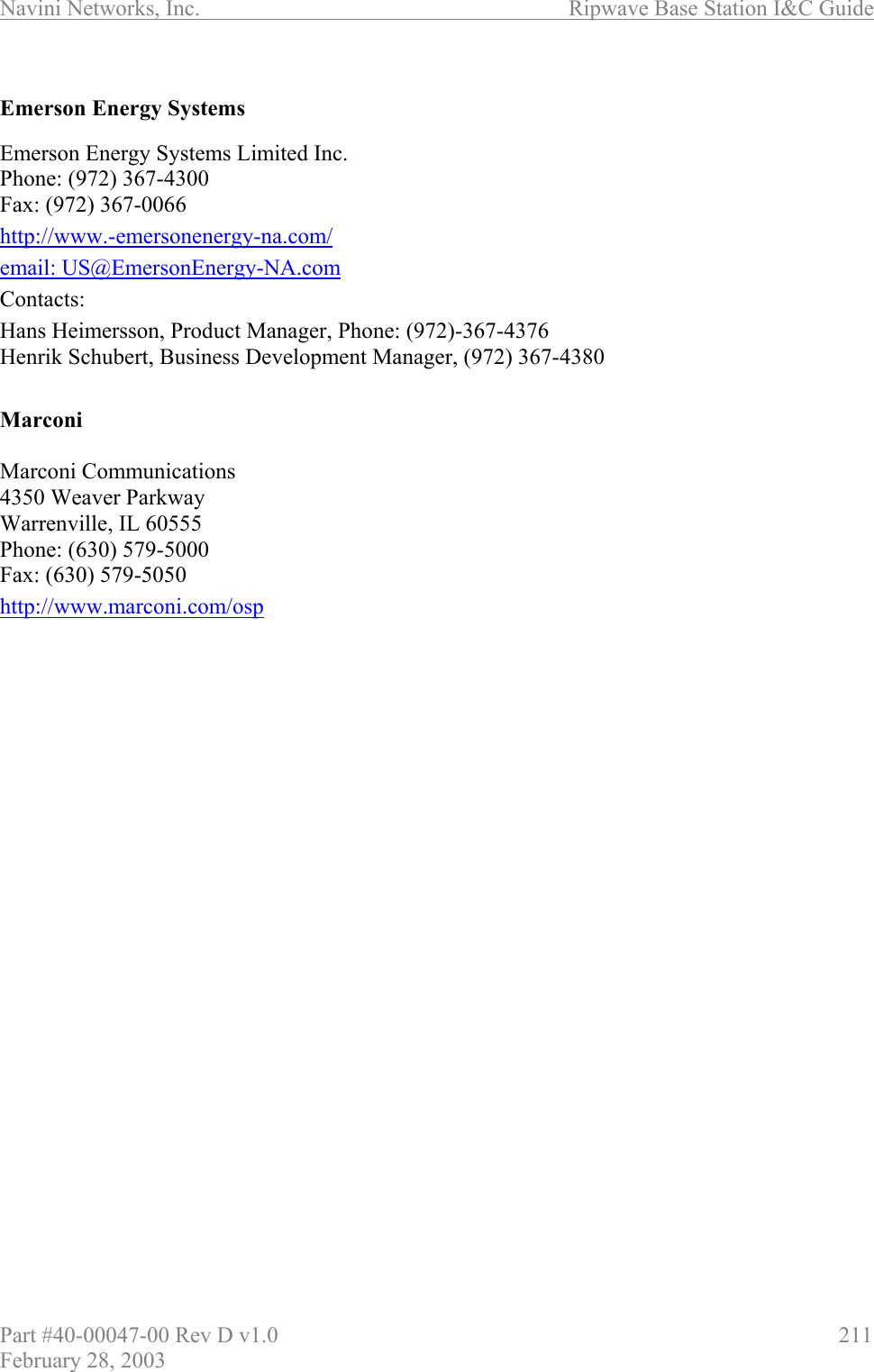
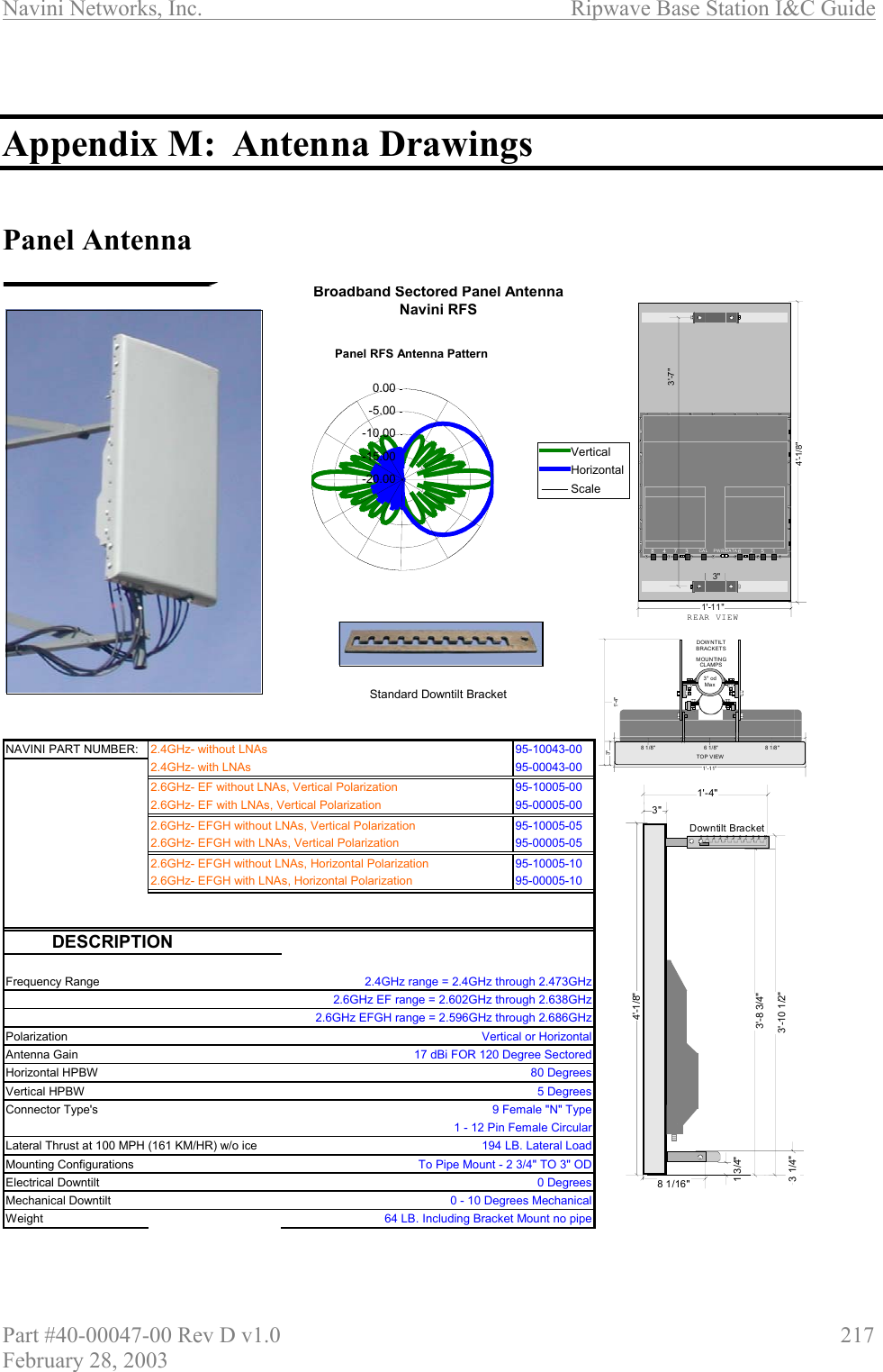
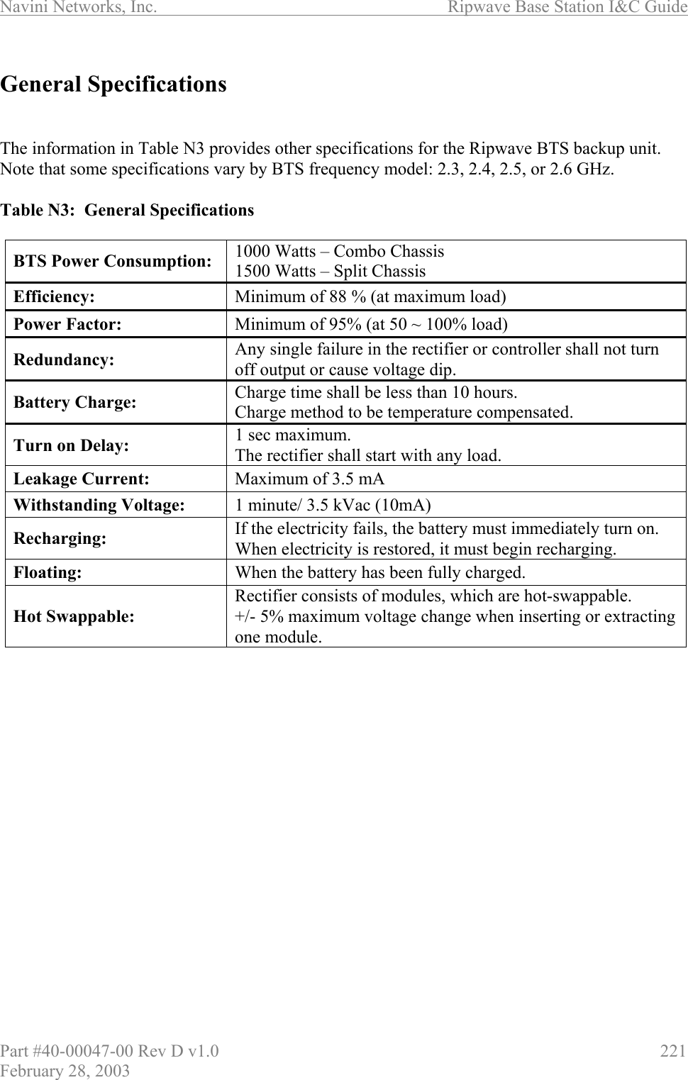
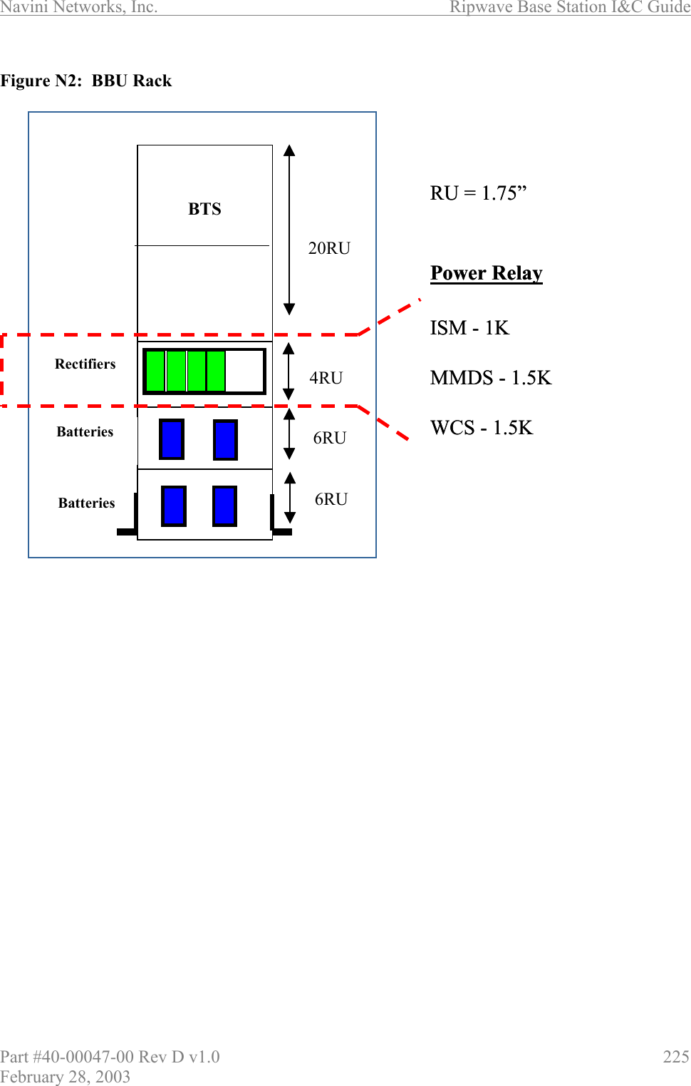
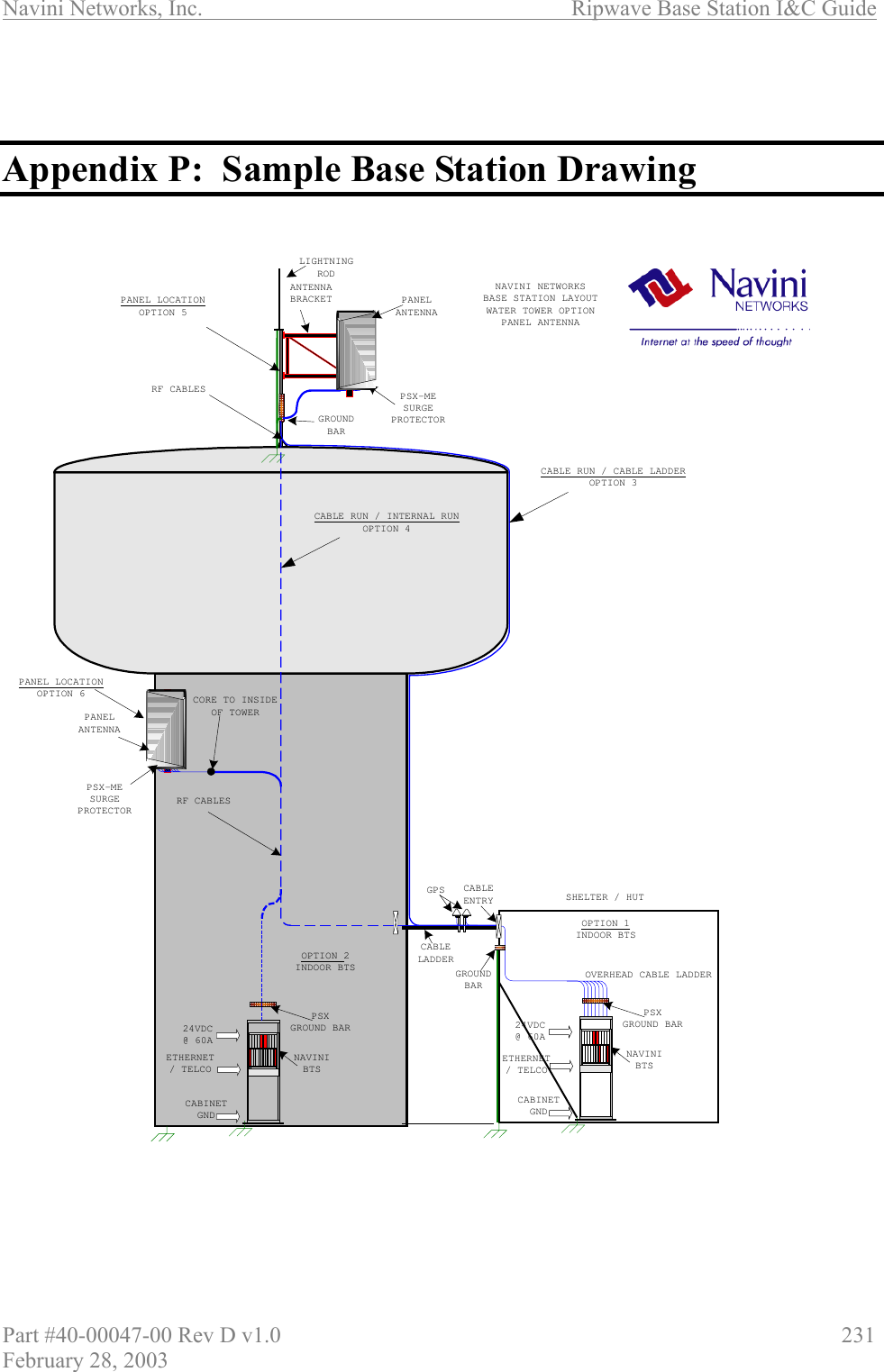
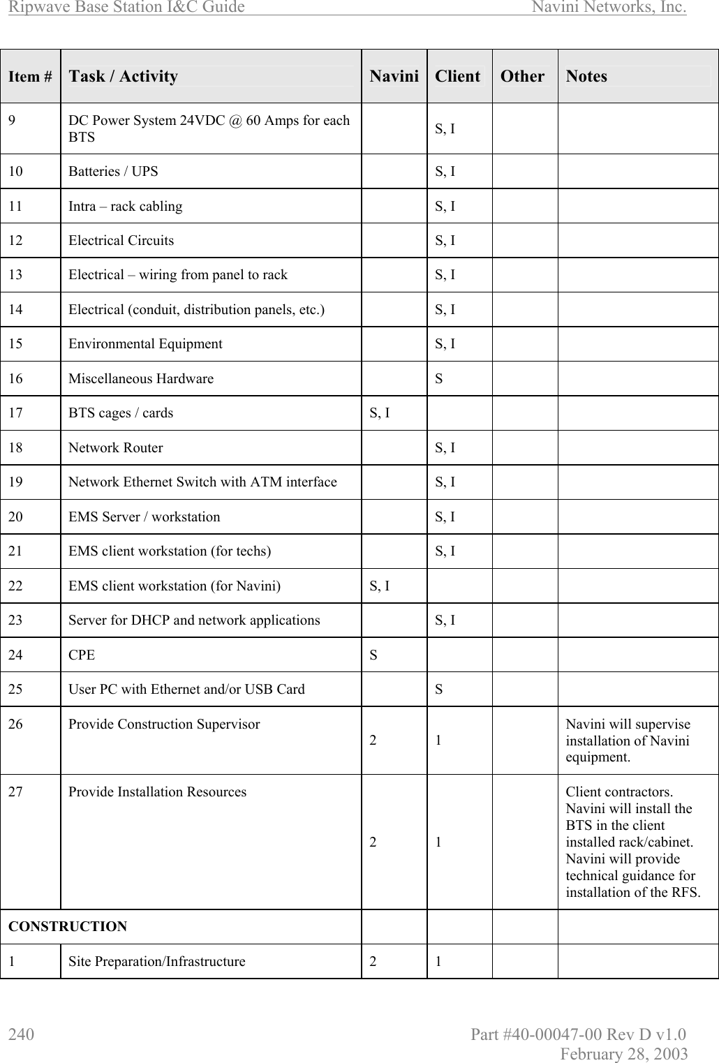
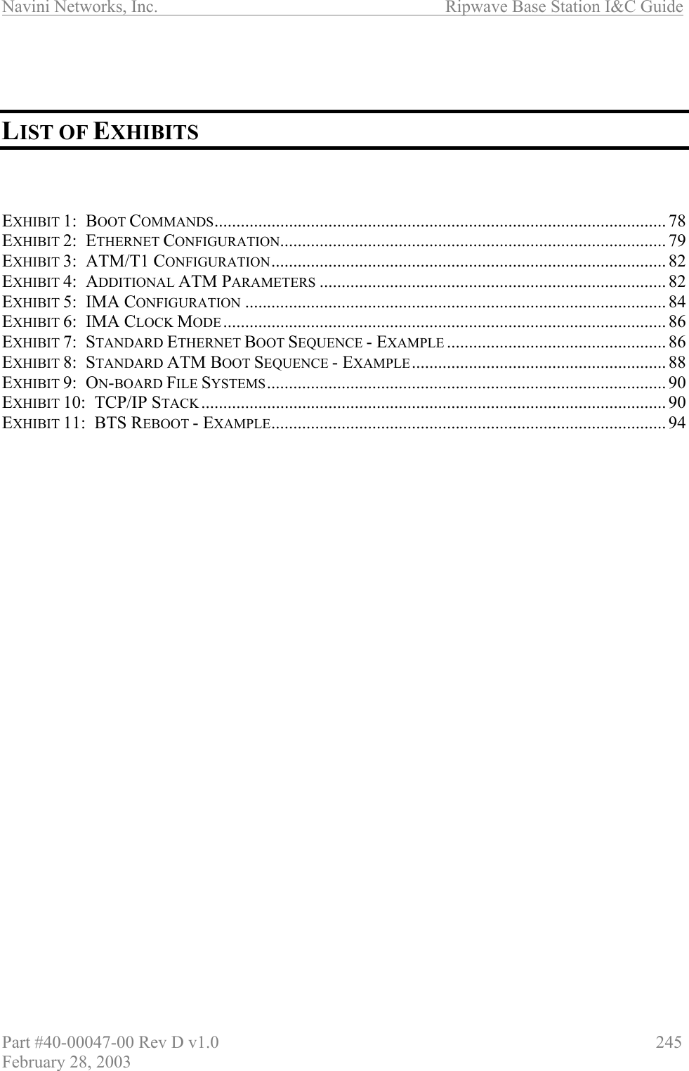
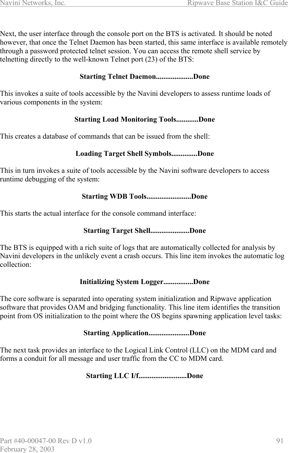
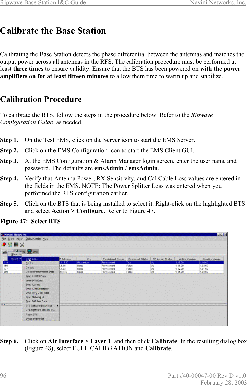
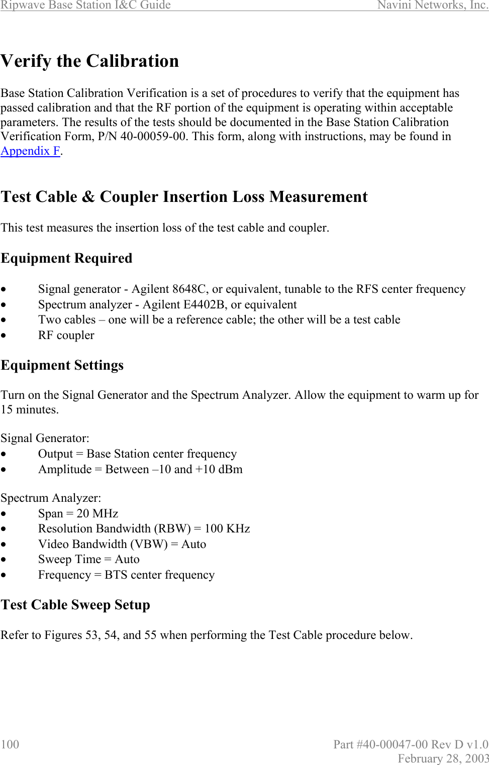
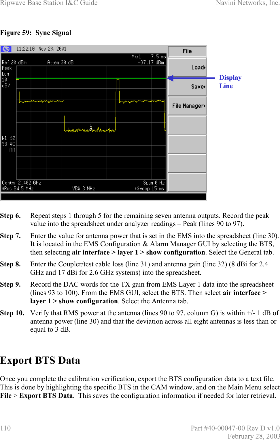
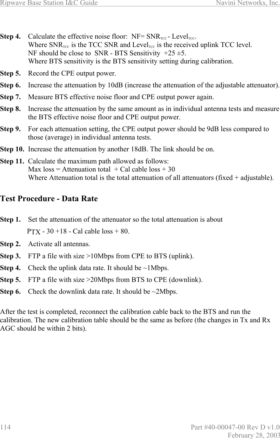
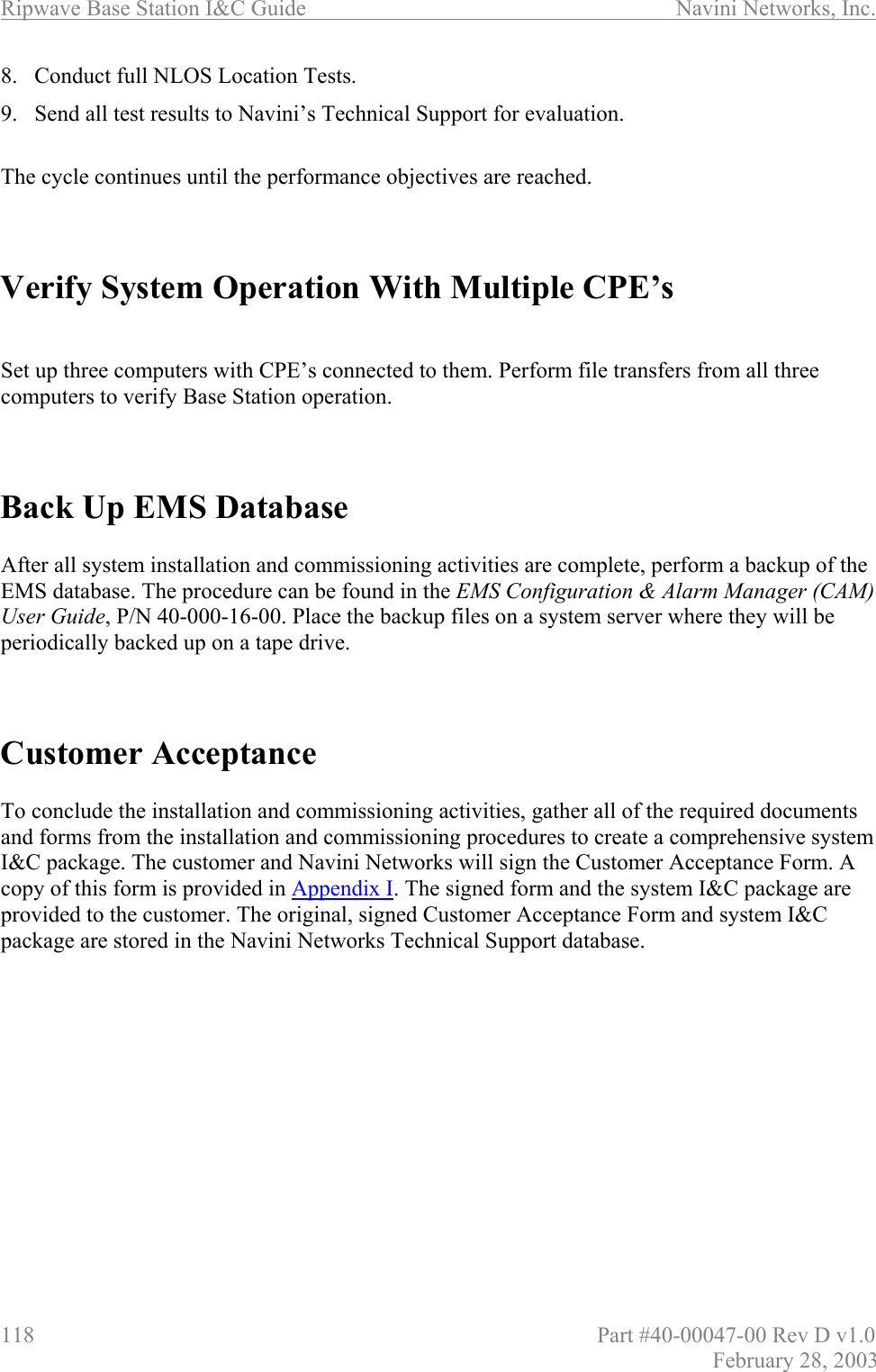
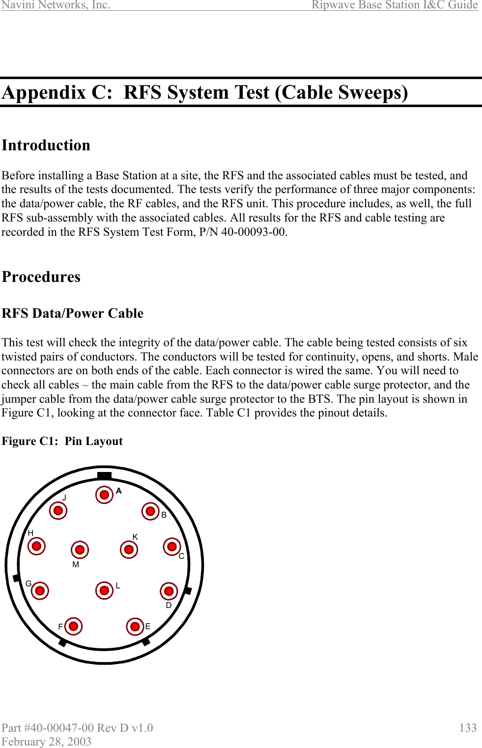
![Navini Networks, Inc. Ripwave Base Station I&C Guide Part #40-00047-00 Rev D v1.0 77 February 28, 2003 Figure 46: BTS Power On Switches Step 3. Watch for the auto-boot countdown command. Type in config on the computer keyboard to interrupt the standard boot sequence. The window of time to type in “config” after auto-boot starts is 20 seconds. BTS Bootup The BTS is shipped with a default value of a 20-second countdown to interrupt the standard bootup sequence. You can escape the standard bootup when the display shows the following: autoboot countdown : quick [quick|delayed] To escape the initialization sequence, type in config before the 20-second counter reaches zero. Note: Under the next section, “Boot Prompt”, you will see how to disable the 20-second countdown in lieu of a shorter, 1-second countdown. This will minimize downtime during unattended restart conditions, for example, if there is a power outage and the BTS is recovering. Off/On switchPowerON/OFFCombo ChassisSplit ChassisOff/On switchPowerON/OFFCombo ChassisSplit Chassis](https://usermanual.wiki/Cisco-Systems/ISM-BTS-R1.Users-Manual-Section2/User-Guide-387217-Page-28.png)
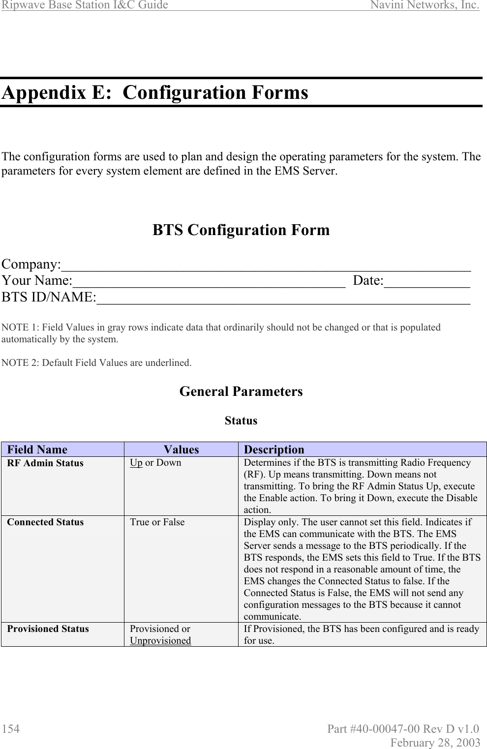
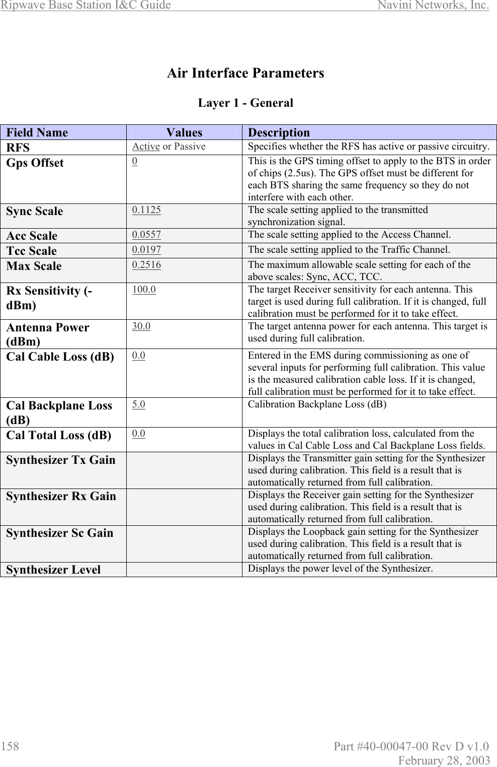
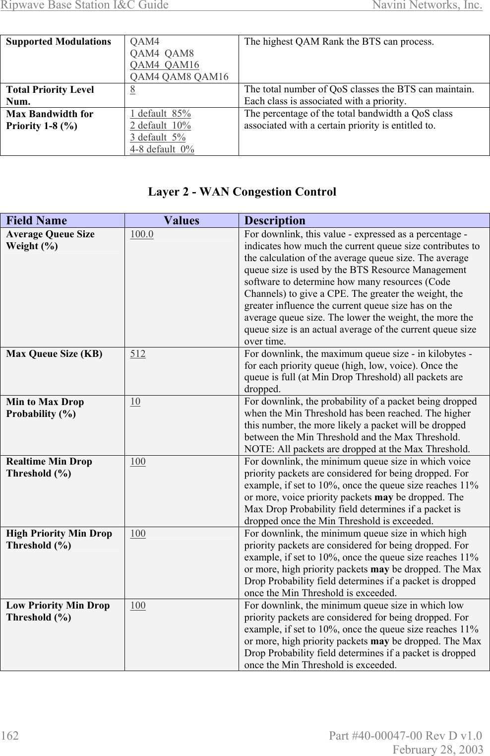
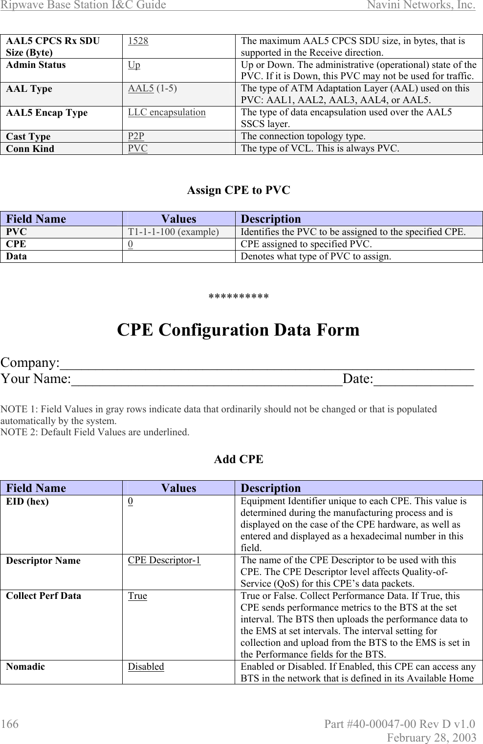
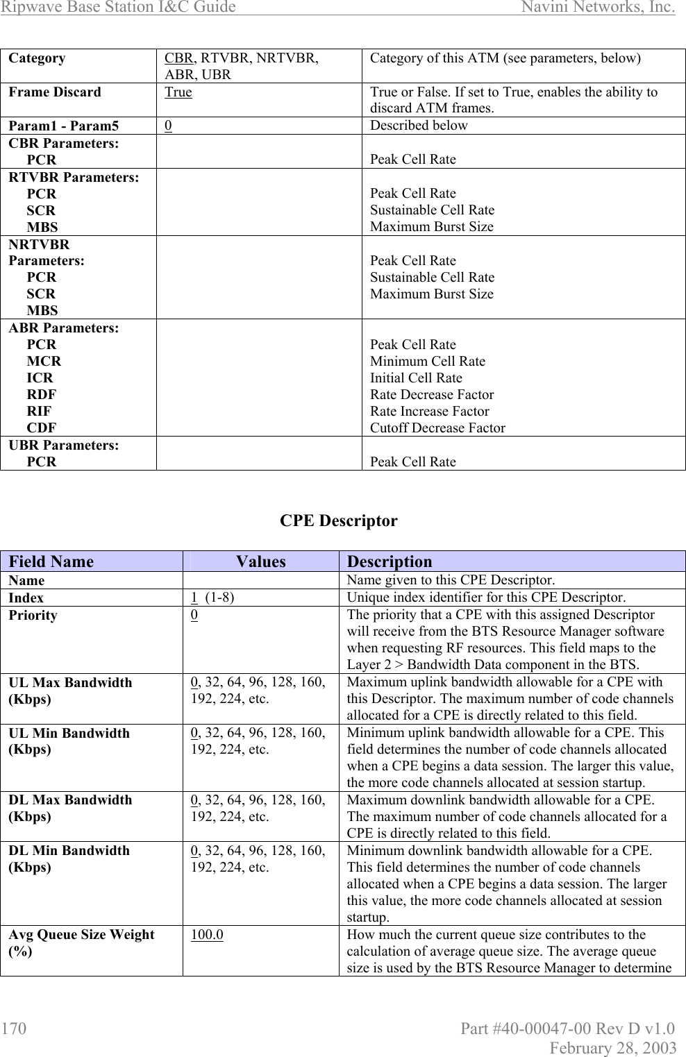
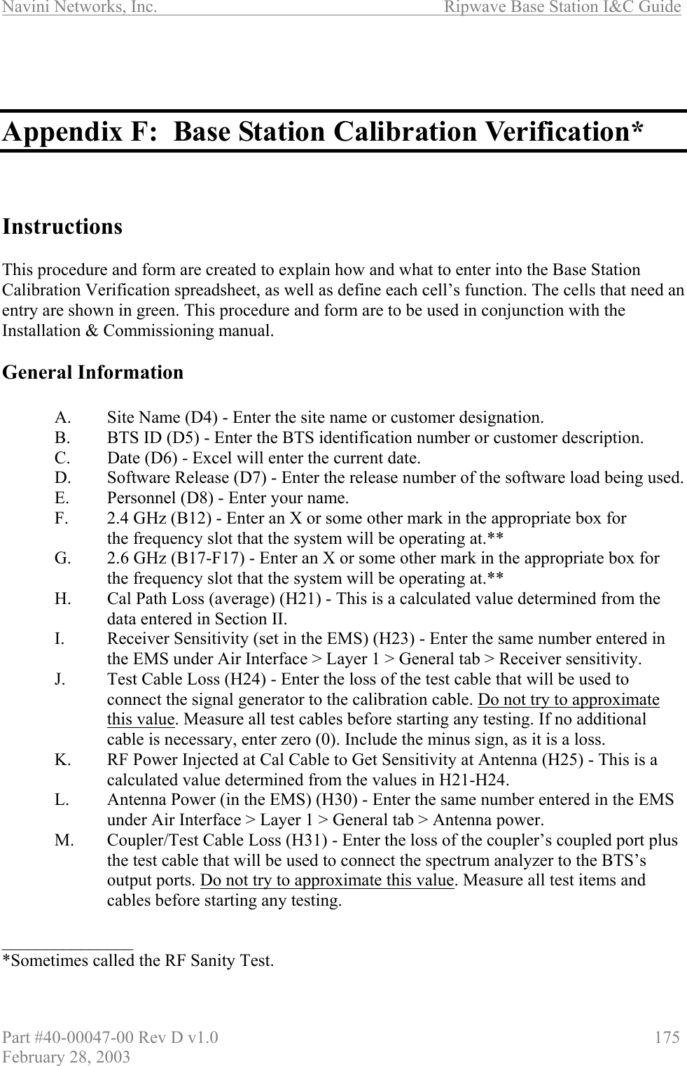
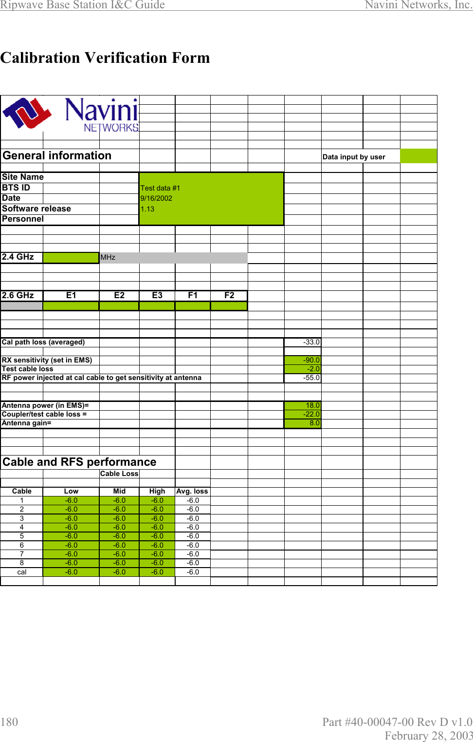
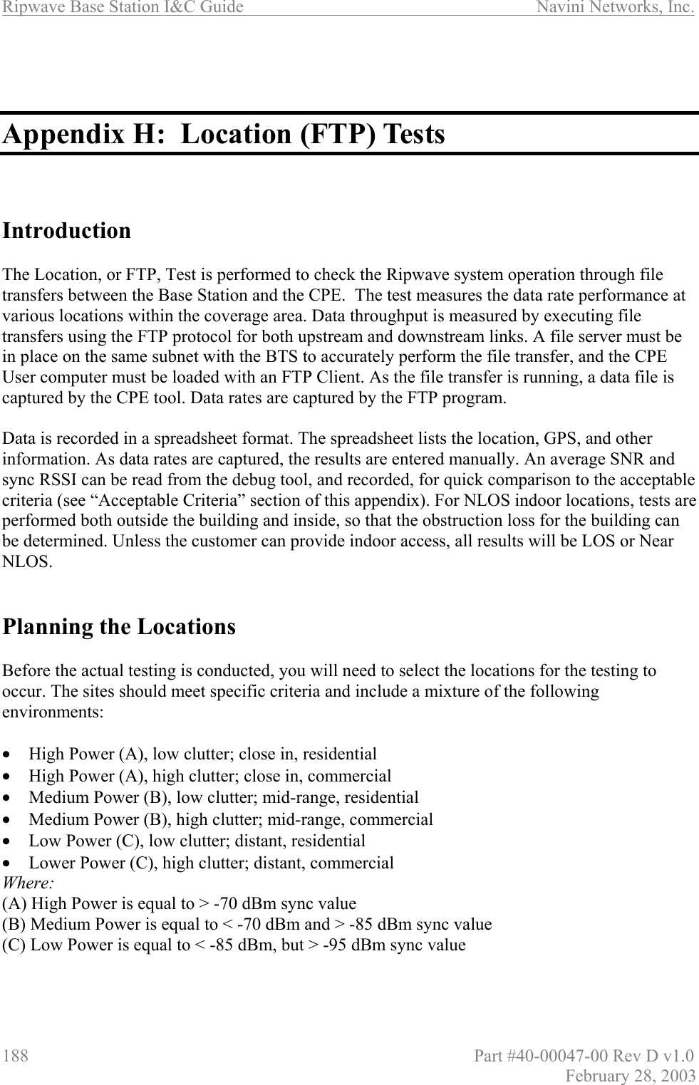
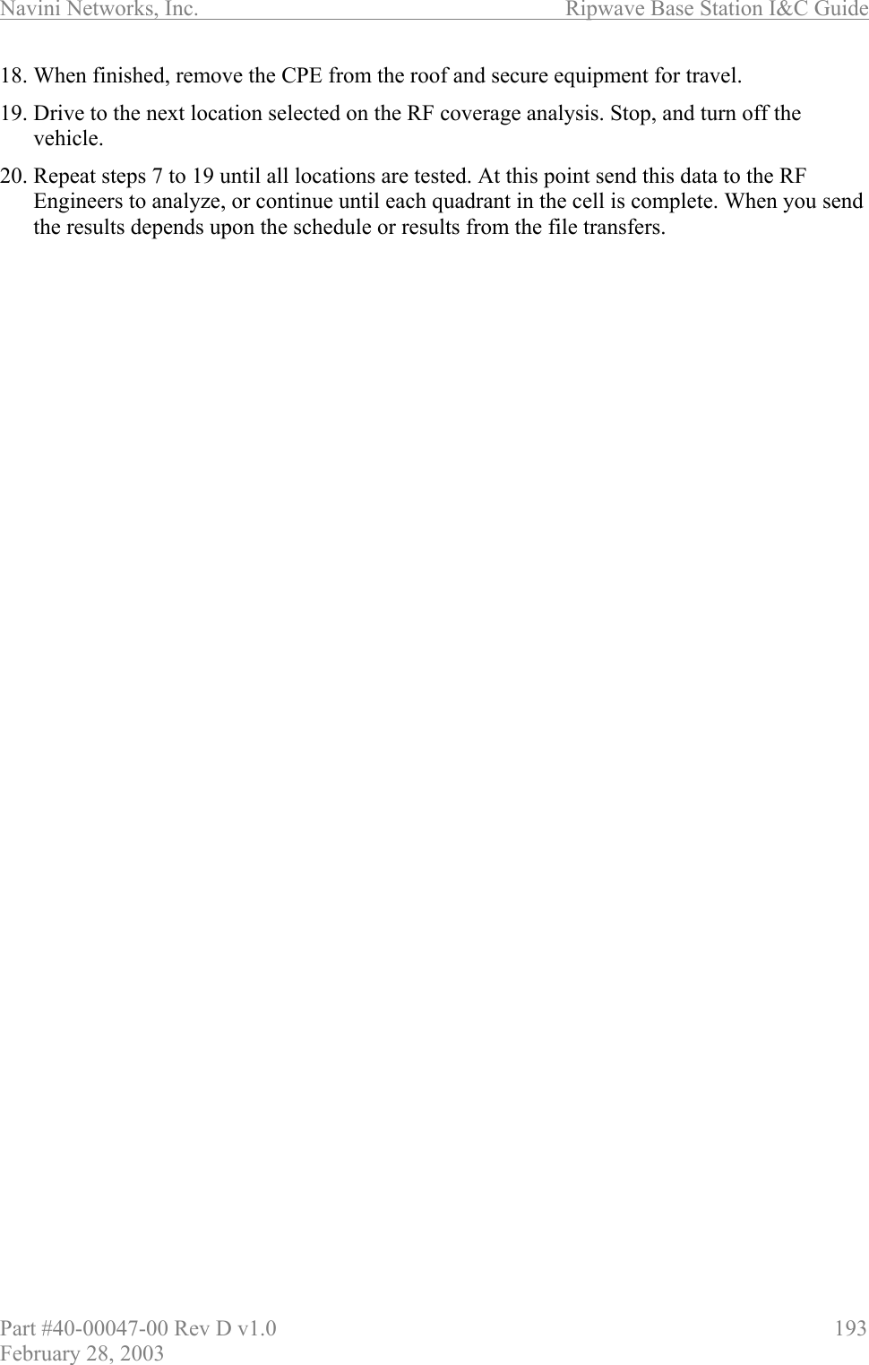
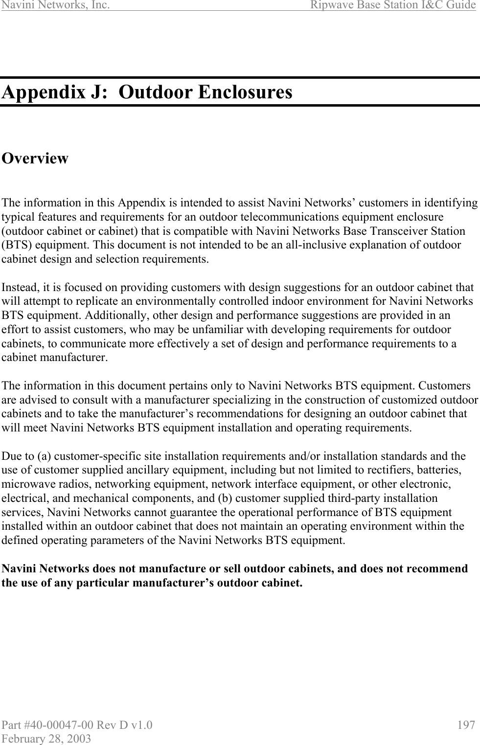
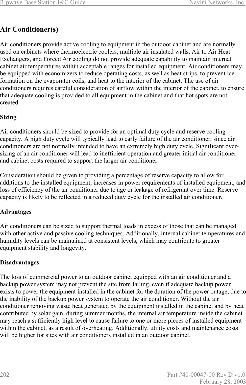
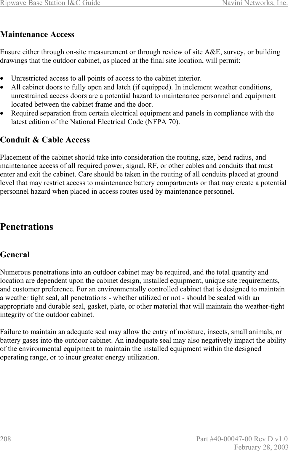
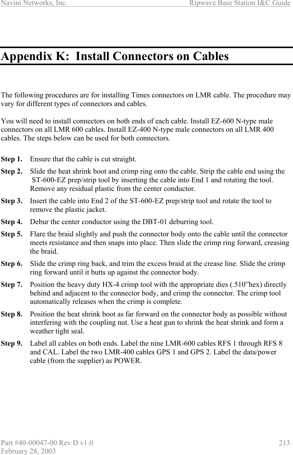
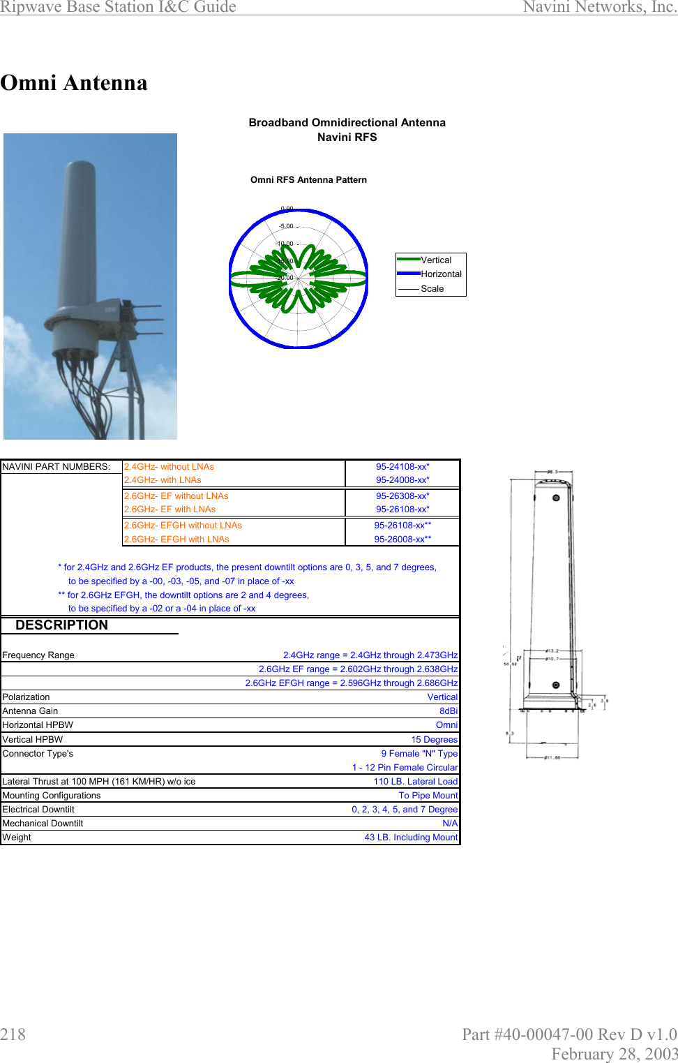
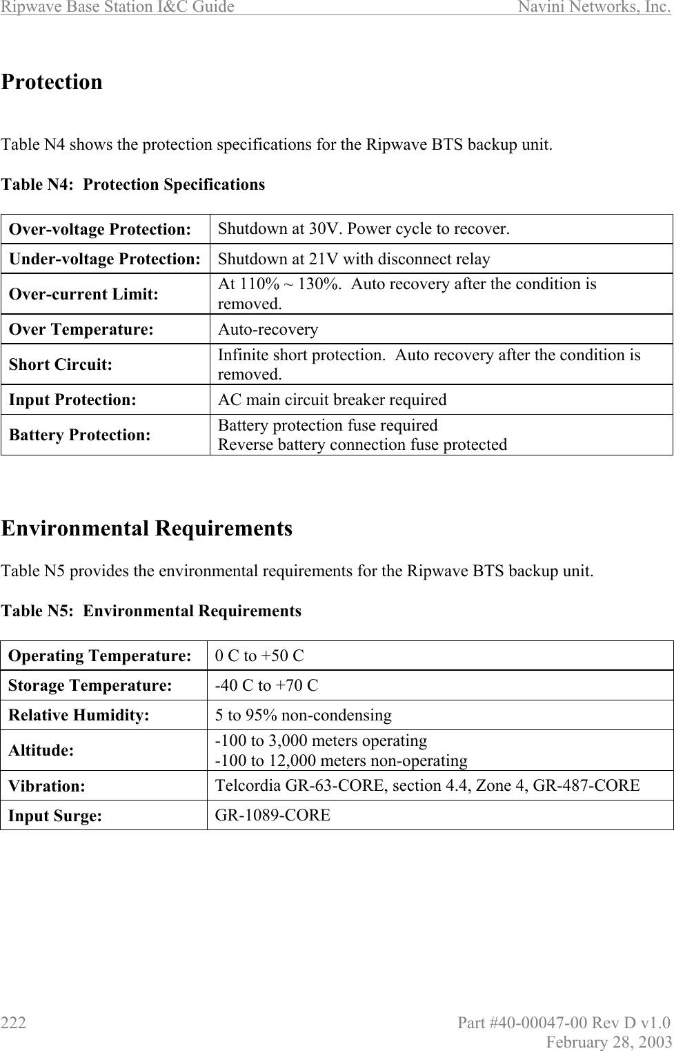
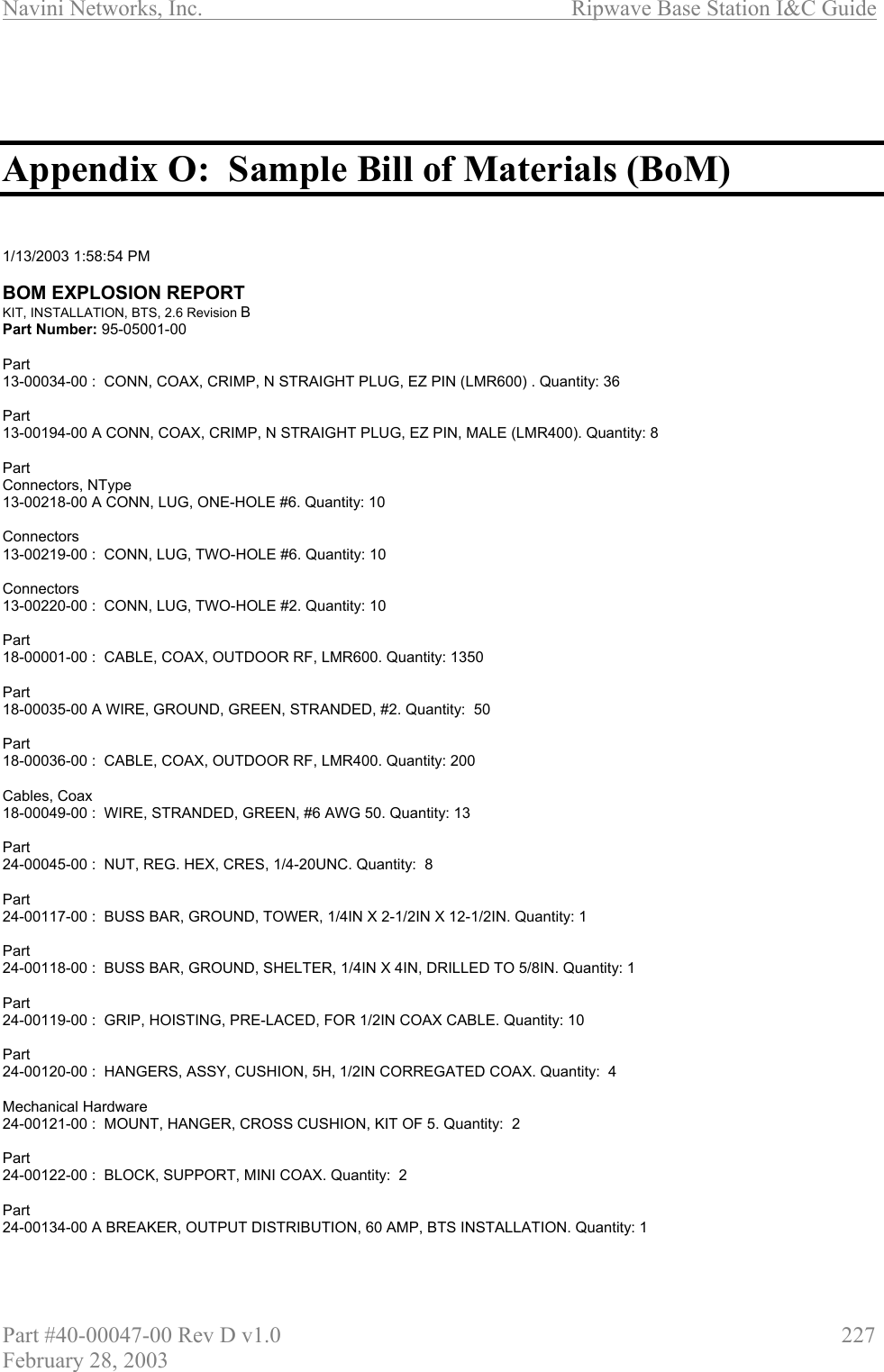
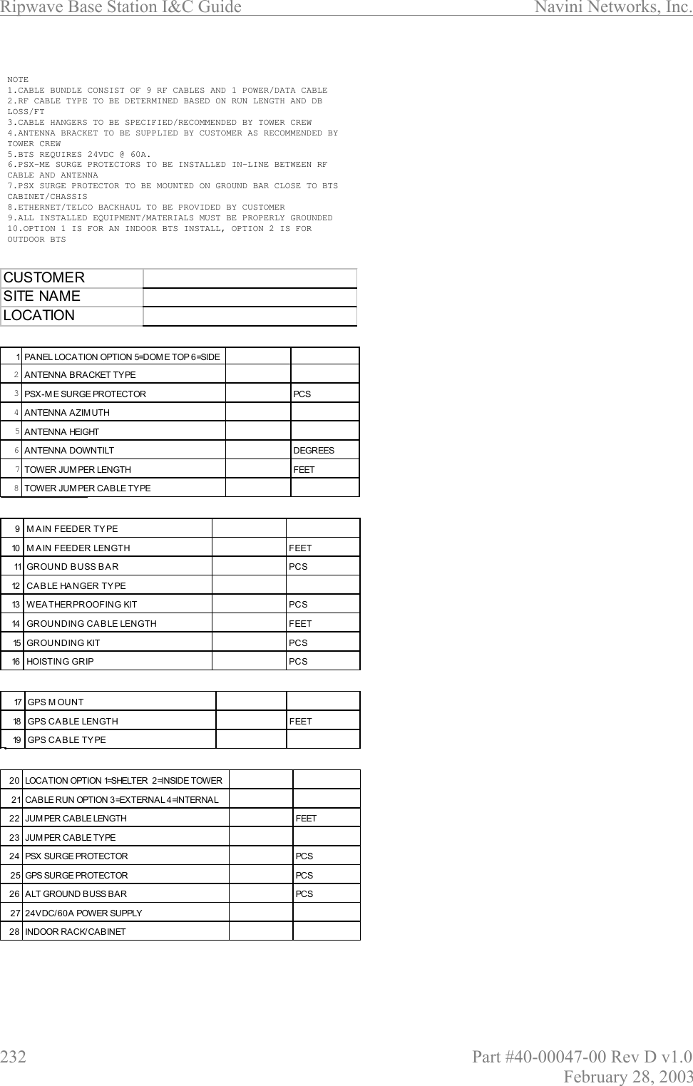
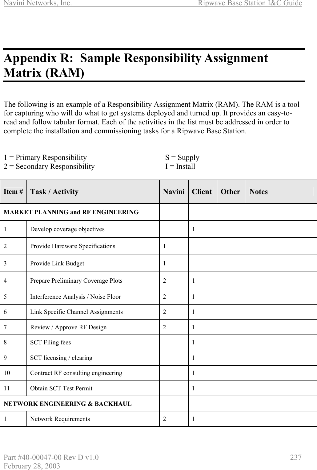
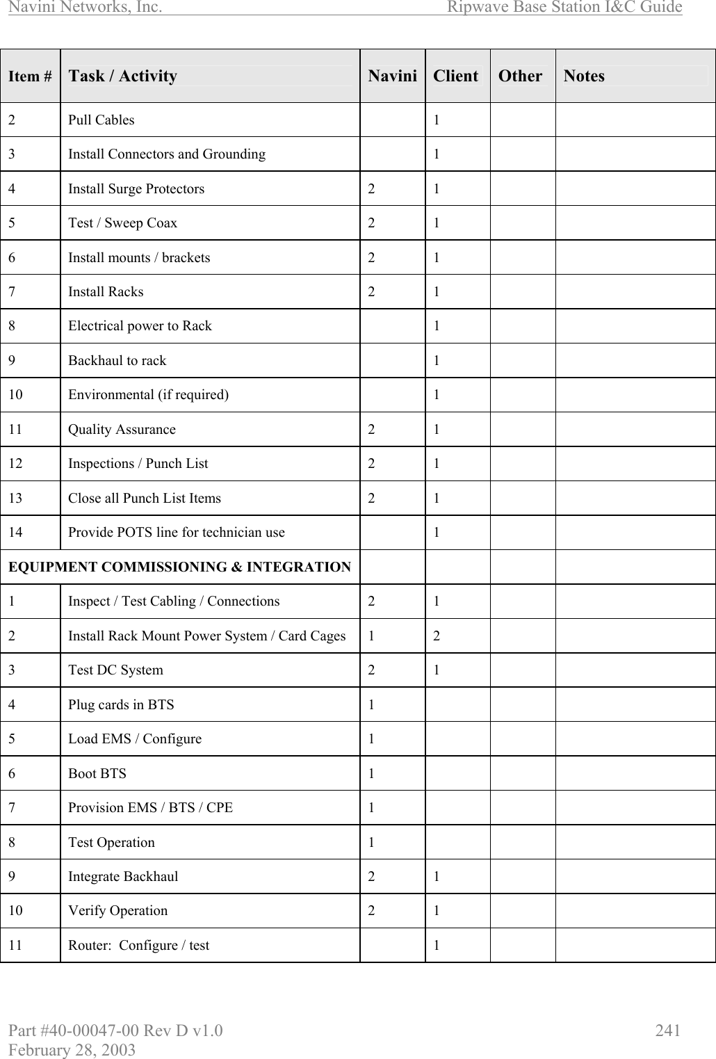
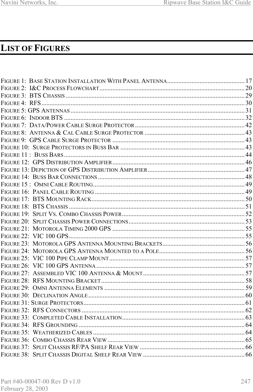
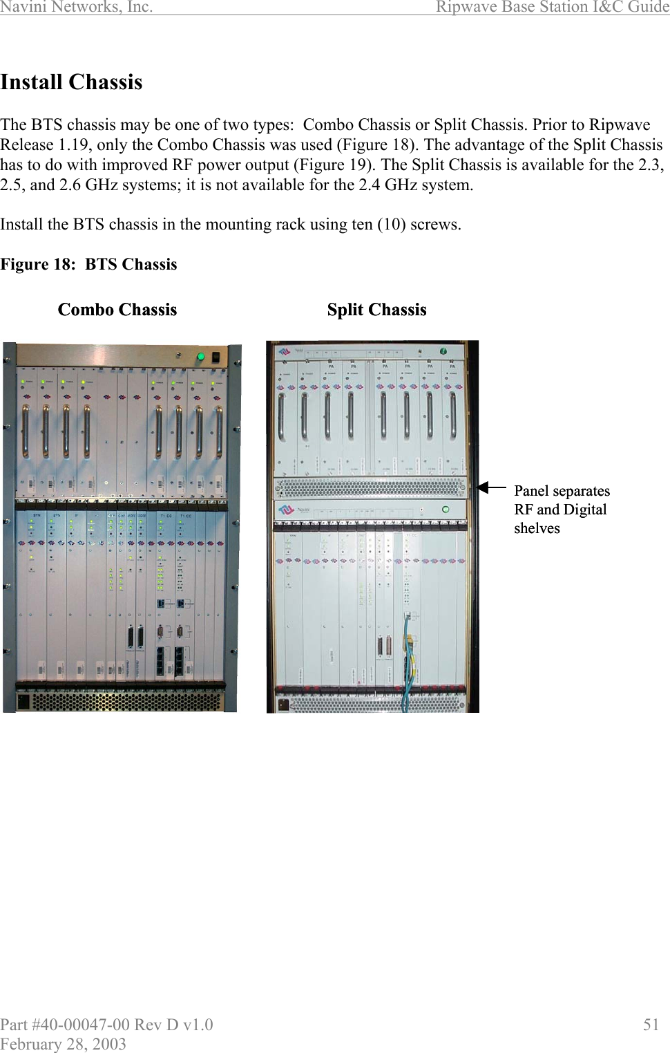
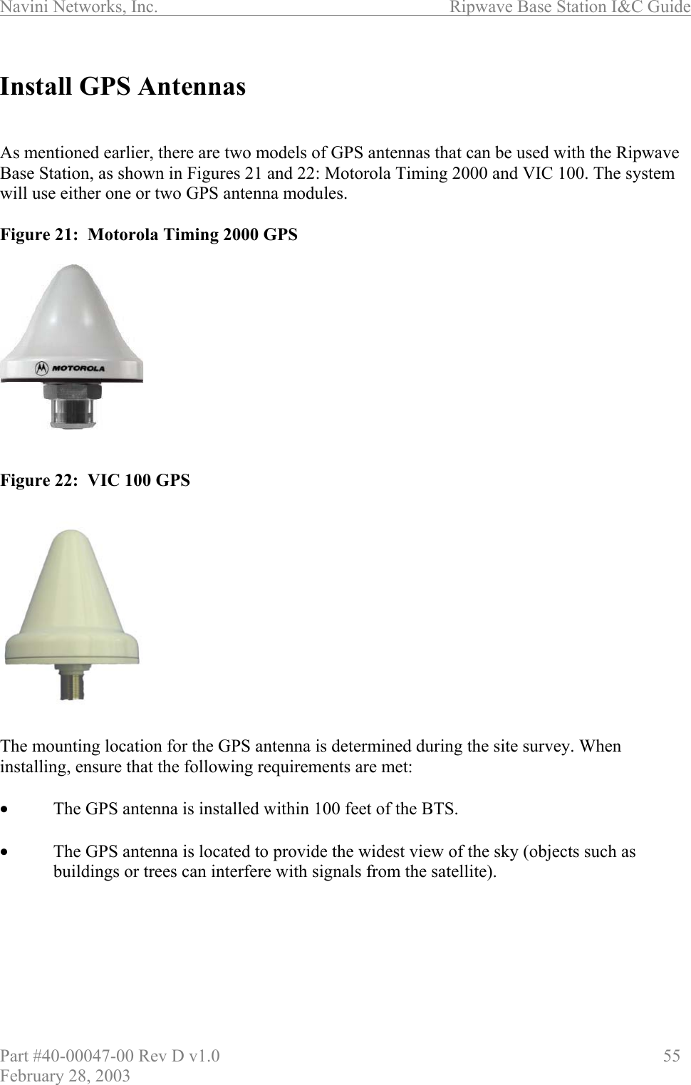
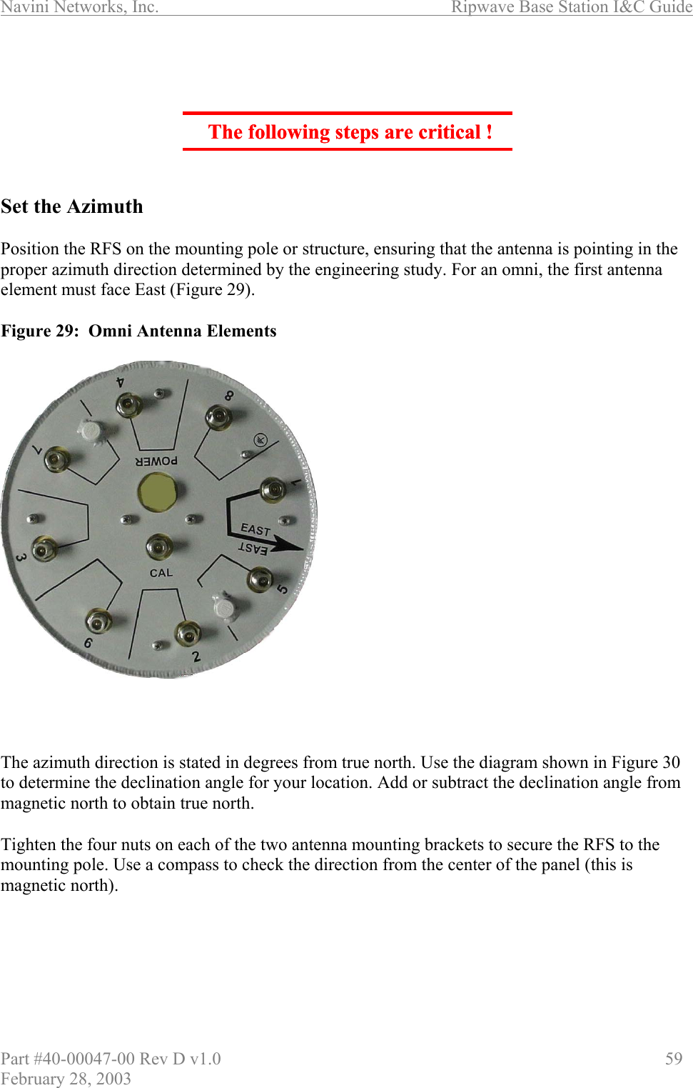
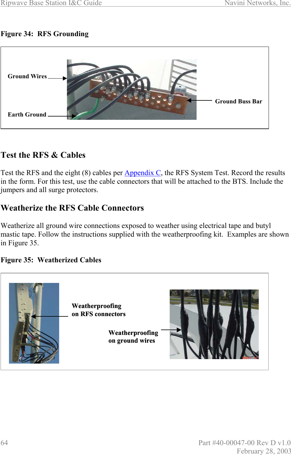
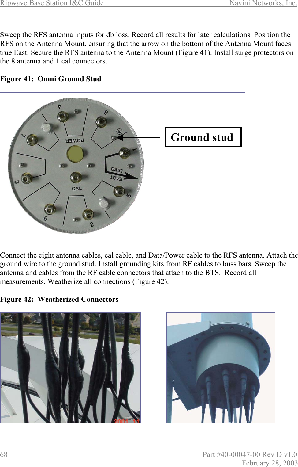
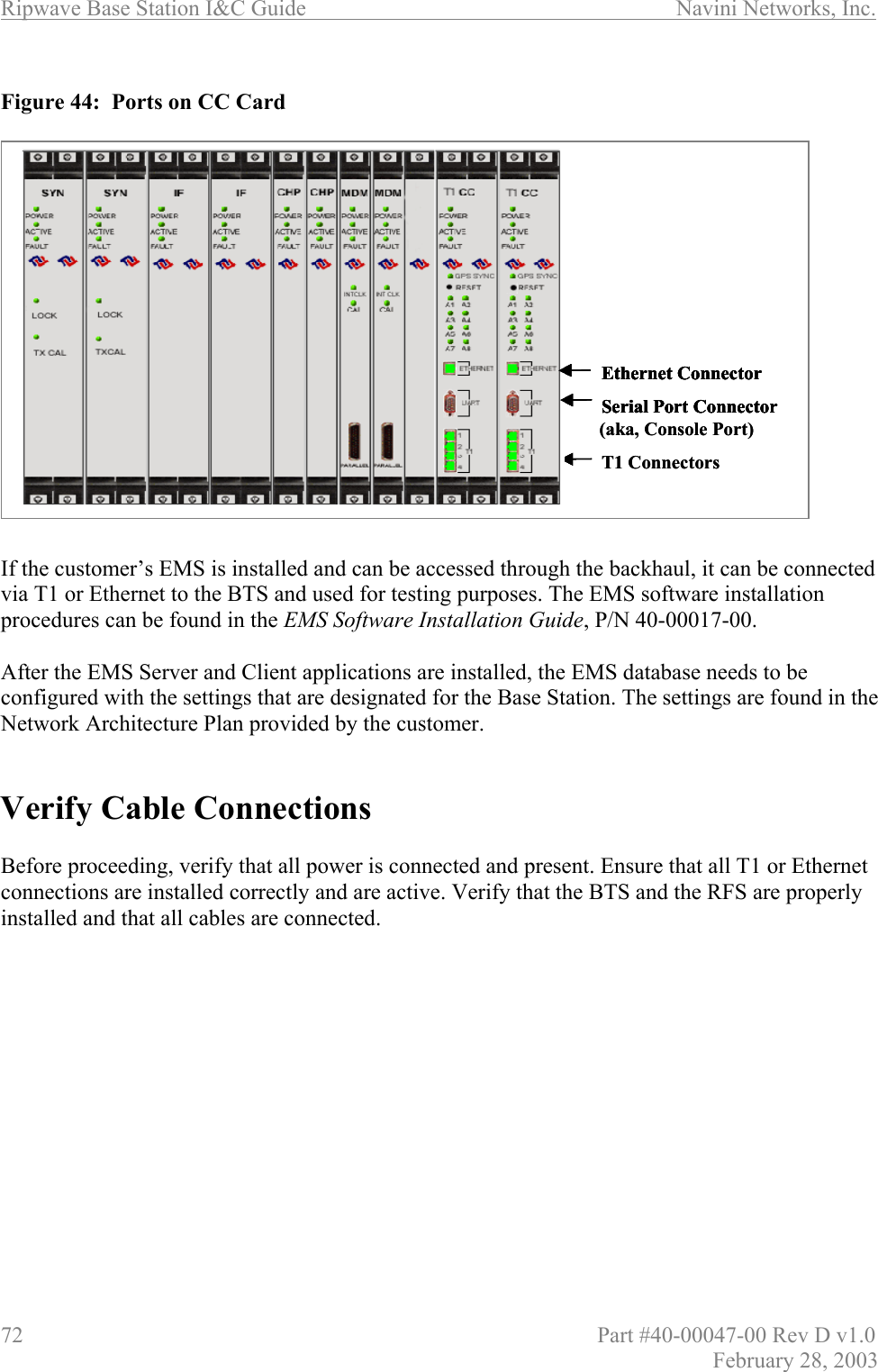
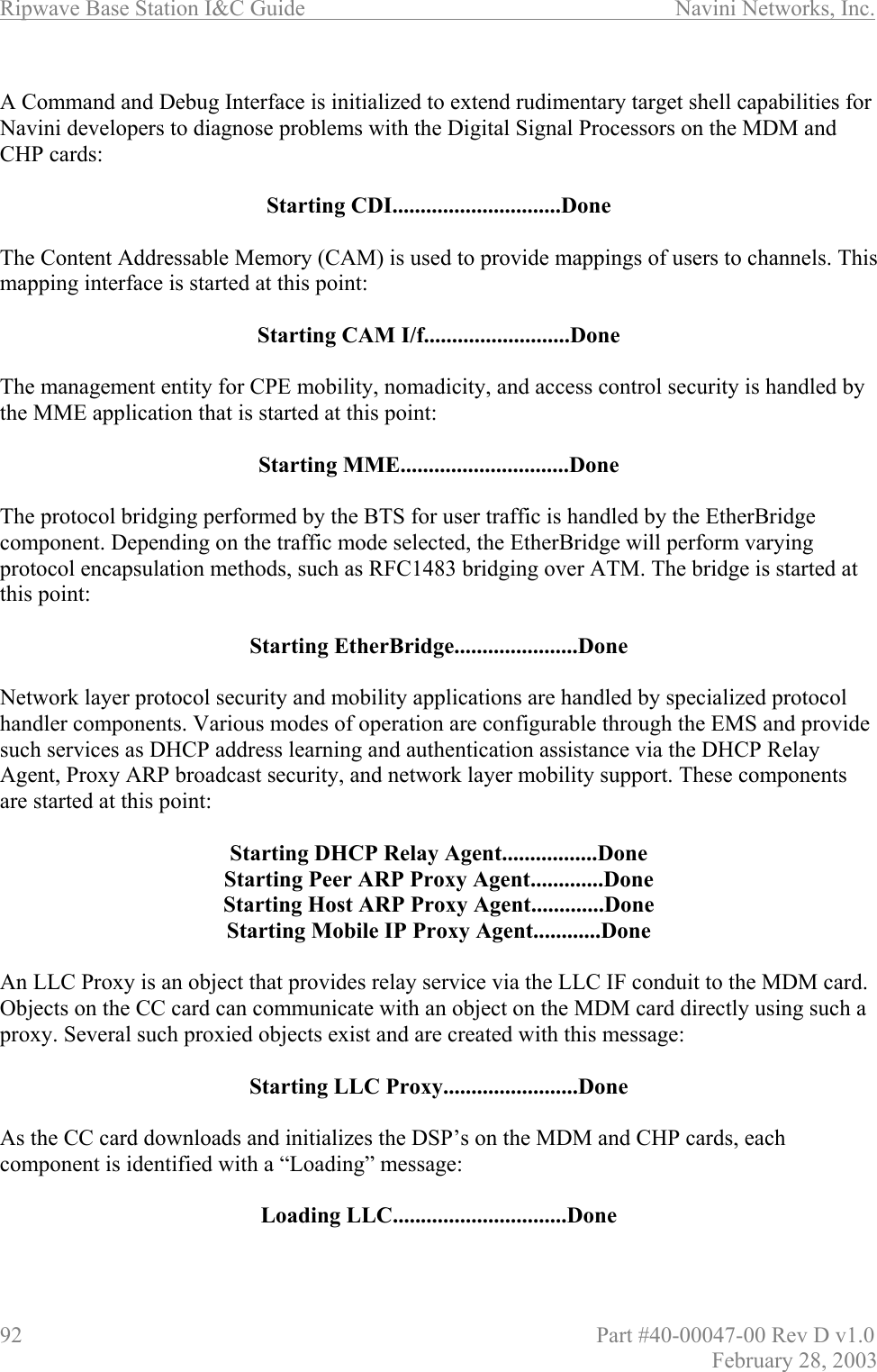
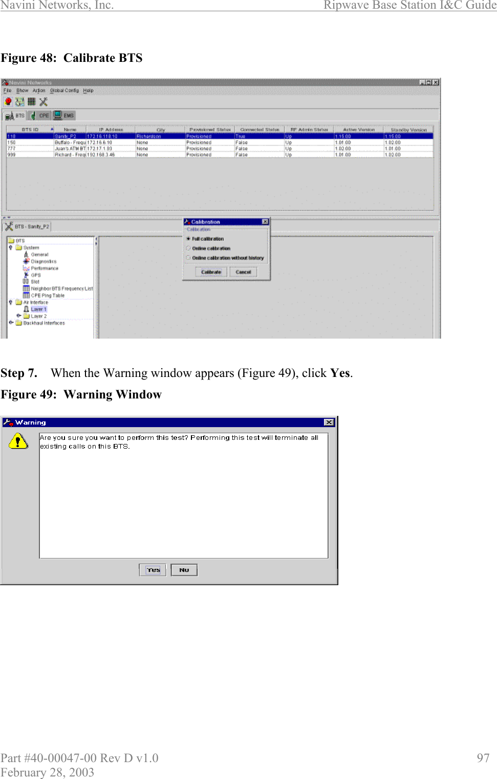
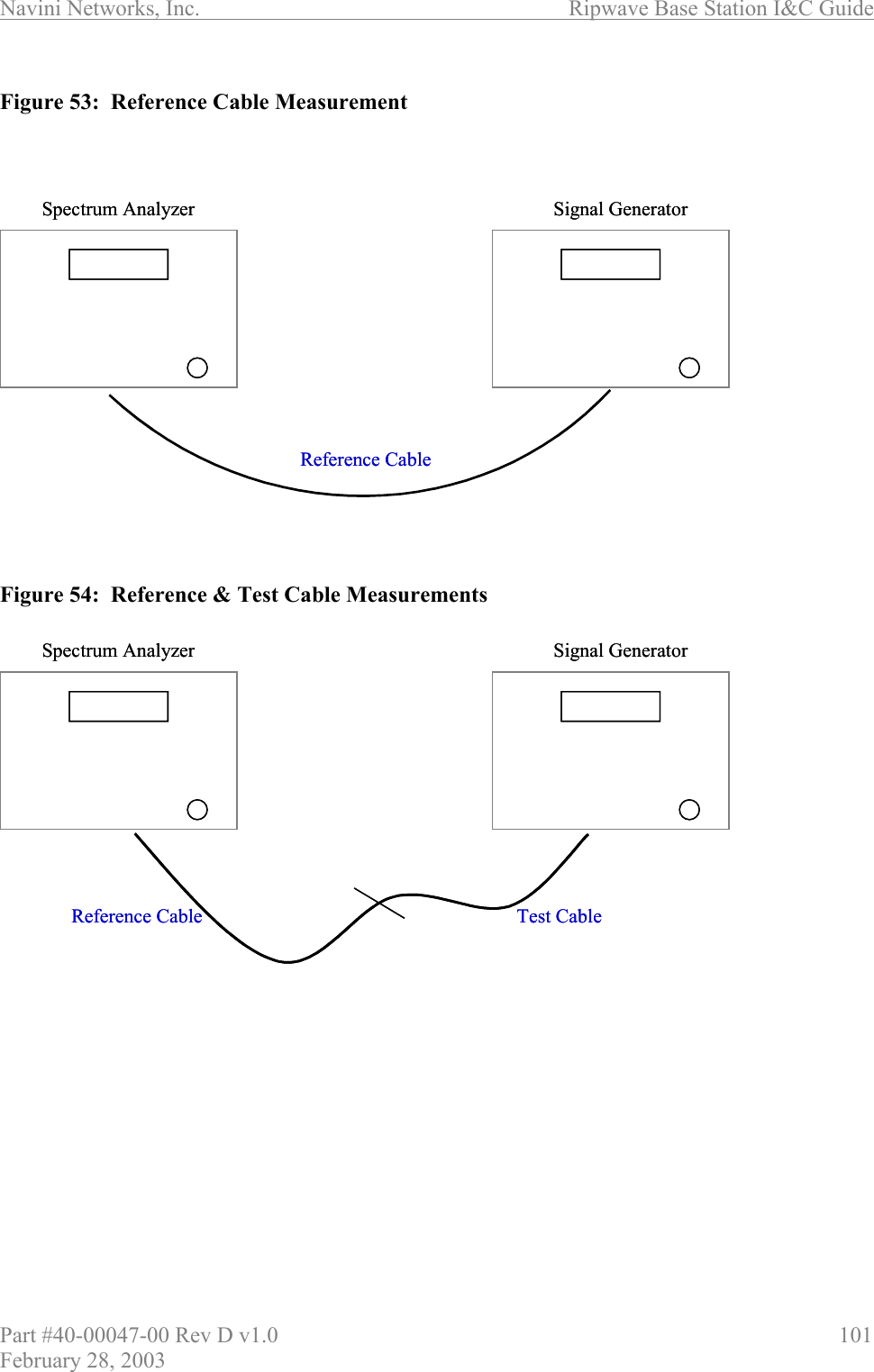
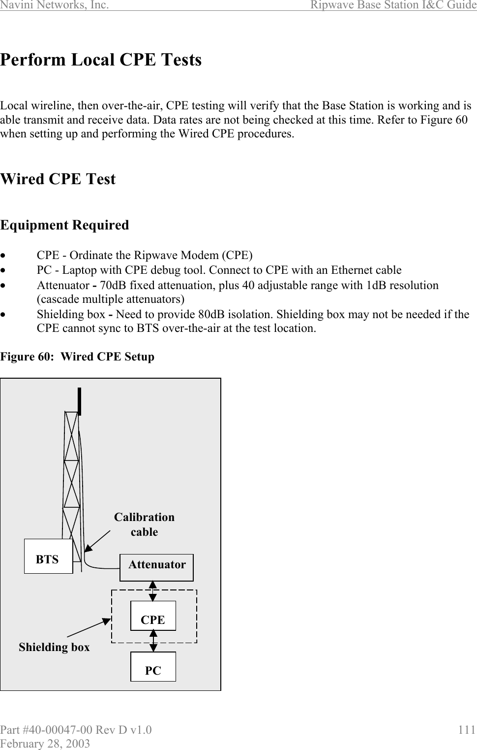
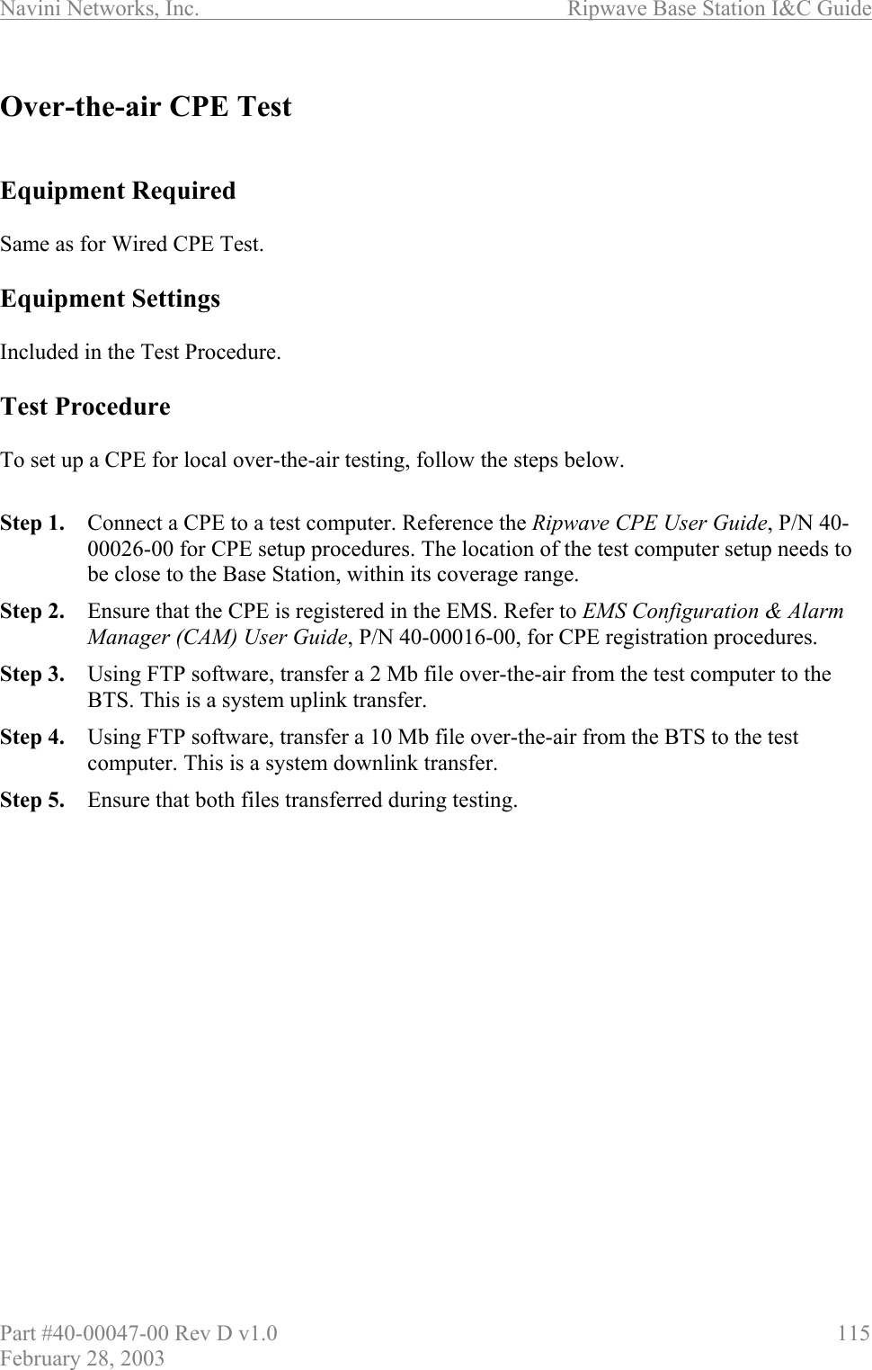
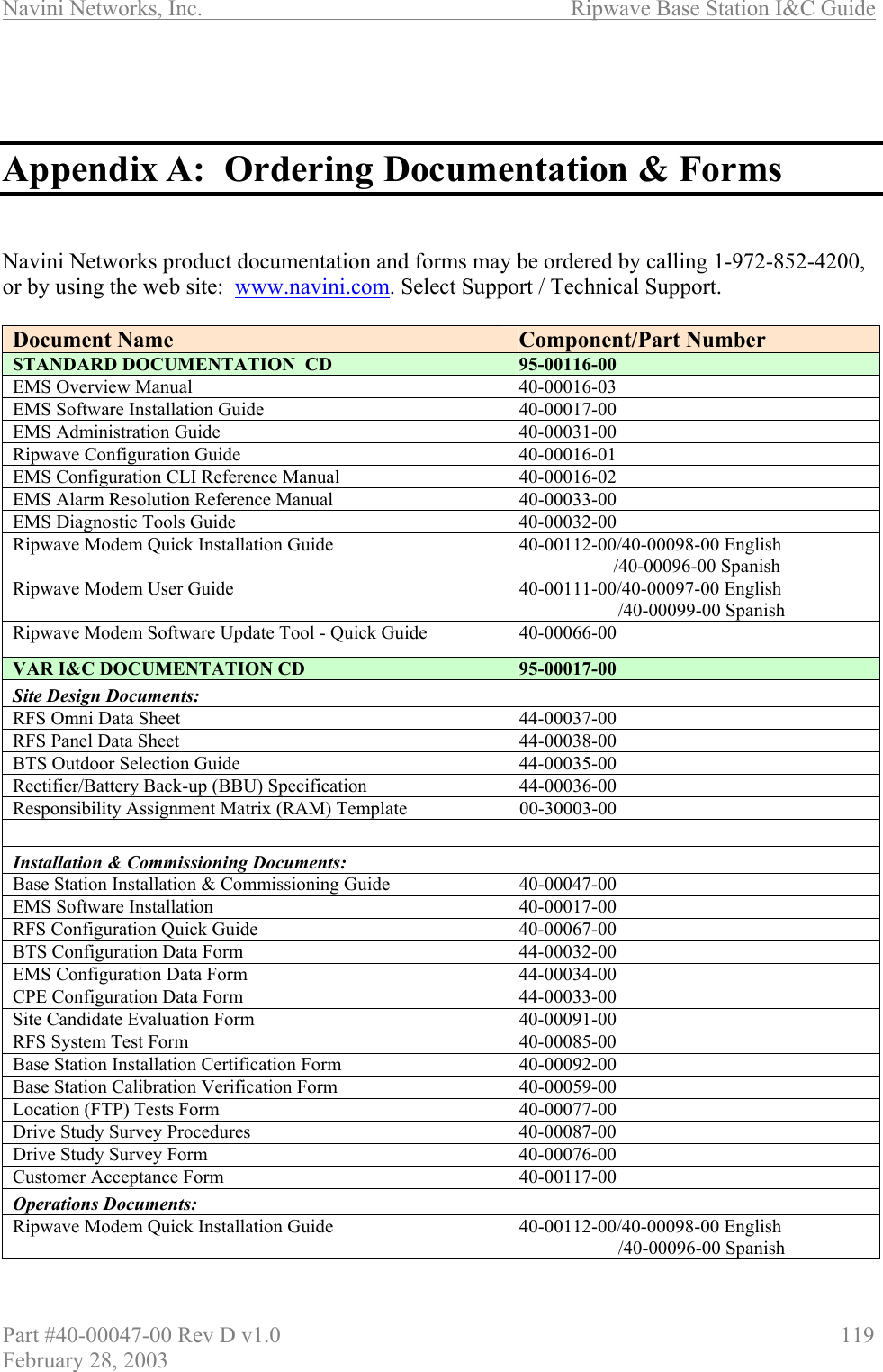
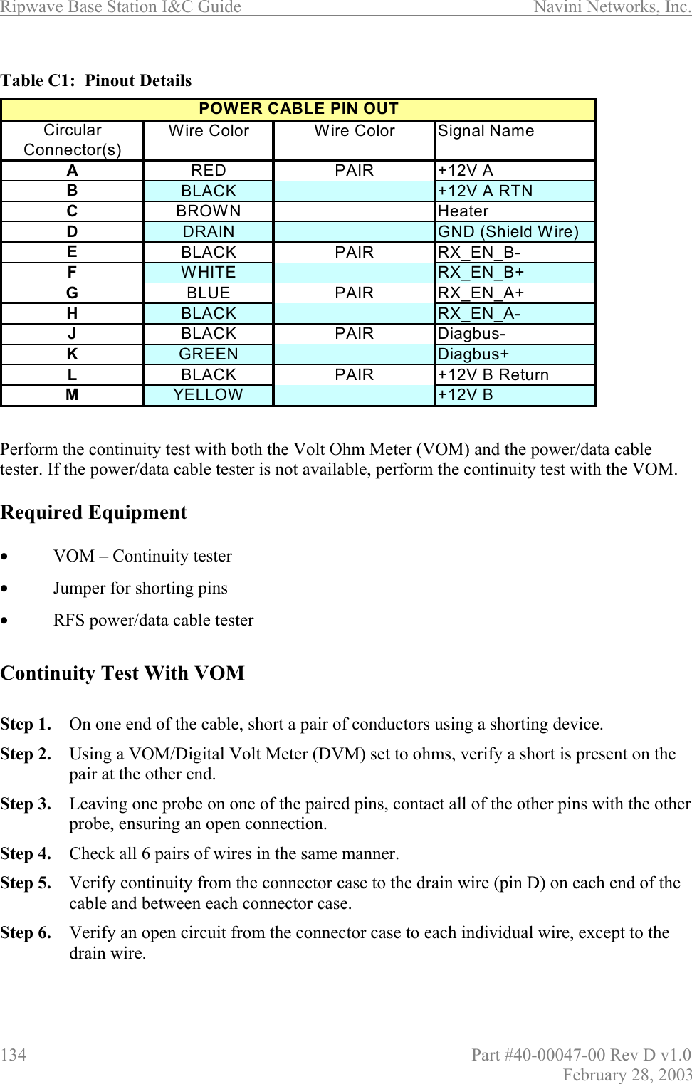
![Ripwave Base Station I&C Guide Navini Networks, Inc. 78 Part #40-00047-00 Rev D v1.0 February 28, 2003 Boot Prompt After you have escaped from the automated boot sequence, the console will display a rudimentary Boot prompt: [Navini Boot]: This prompt offers the ability to perform a small set of operations. Enter ‘?’ or ‘h’ followed by the Enter key to display a list of commands (Exhibit 1). To invoke any of the commands, simply enter the single letter command with optional parameters, followed by the Enter key. . Exhibit 1: Boot Commands [Navini Boot]: ??-print this list@-resume boot sequencep -print boot paramsc-change boot params d adrs[,n] -display memory m adrs-modify memory f adrs, nbytes, value - fill memory t adrs, adrs, nbytes - copy memory @ – Use this command once all parameters have been set as desired. This will resume the boot initialization sequence that you escaped from previously. p – This command displays a concise representation of the current parameters used for boot configuration. c – Use this command to alter the current boot parameters. Once selected, a detailed sequence of options is prompted, and is covered in detail later. After all of the items in this list are completed, you return to the [Navini Boot]: prompt. This option sequence allows you either to accept the current value by pressing the Enter key or to enter a new value from the range or values listed, followed by the Enter key. Additionally, you can enter ‘.’ followed by the Enter key to erase the current value of an item and return it to a default state. If you make an error, you can choose ‘-‘ (hyphen) followed by the Enter key to return to the previous item in the list. Alternatively, you can fix an error by proceeding with the selections and select ‘change' when you return to the [Navini Boot]: prompt. d – Display memory allows you to display portions of the BTS’s memory with user-defined values. It should only be performed with the assistance of a certified Navini service technician. m – Modify memory allows you to alter portions of the BTS’s memory with user defined values. It should only be performed with the assistance of a certified Navini service technician.](https://usermanual.wiki/Cisco-Systems/ISM-BTS-R1.Users-Manual-Section2/User-Guide-387217-Page-29.png)
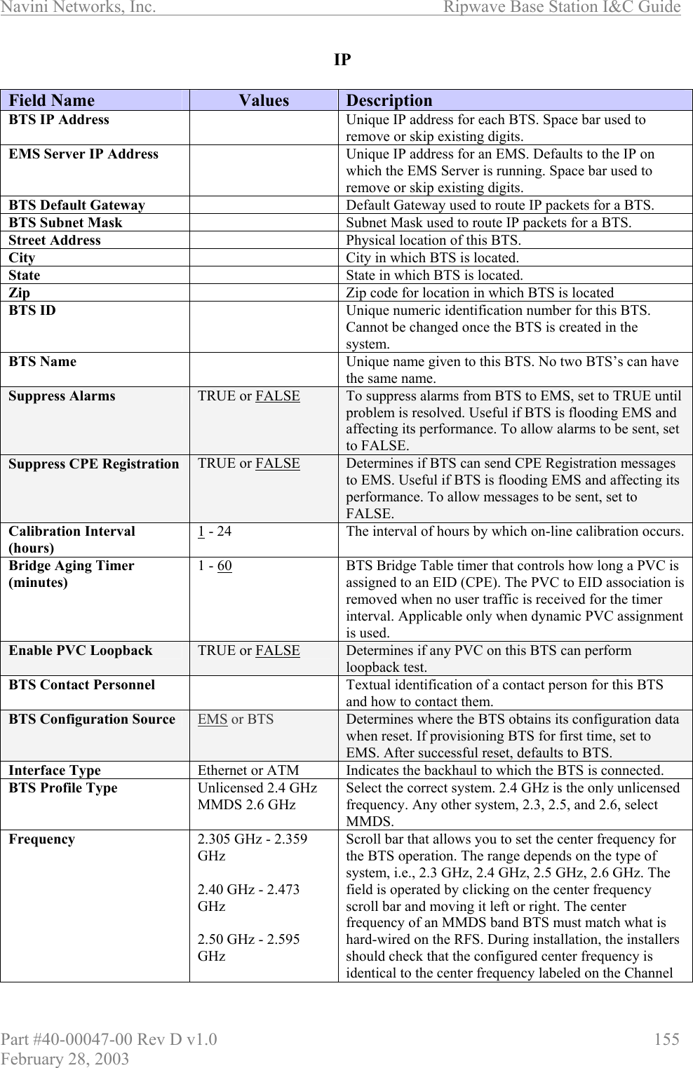
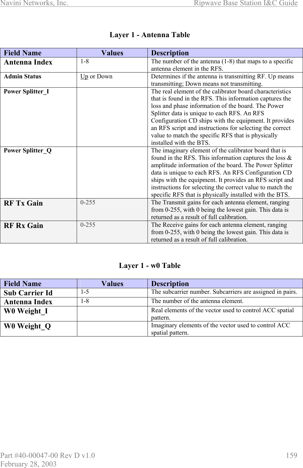
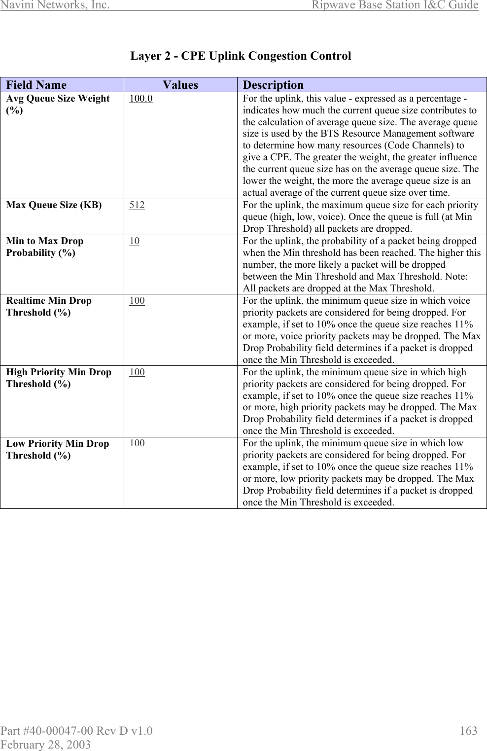
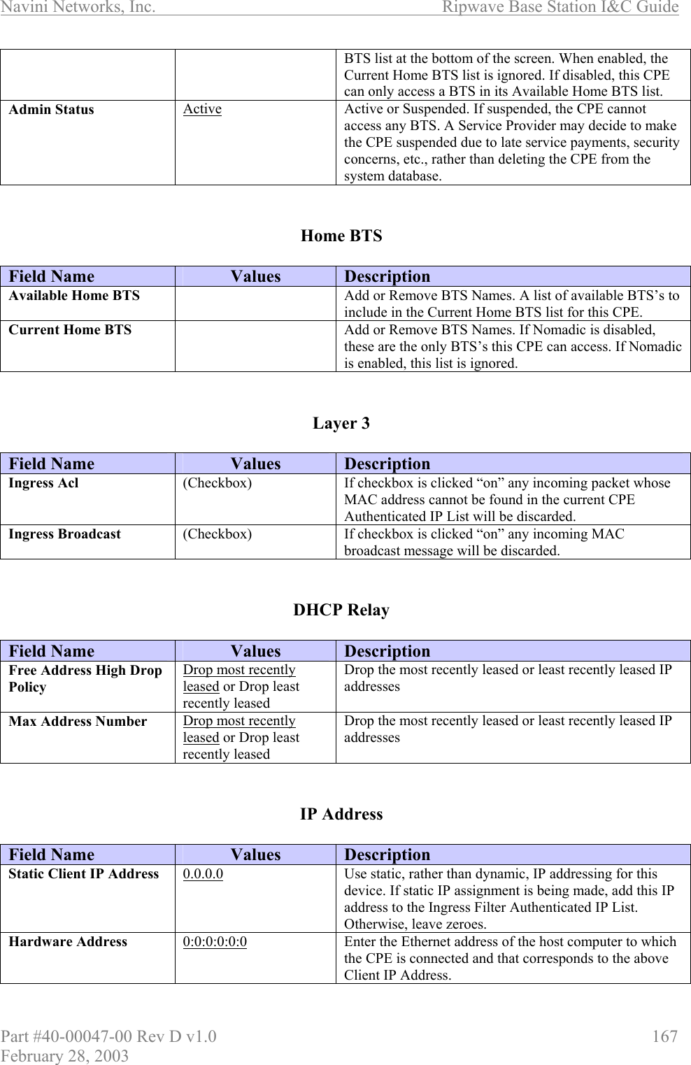
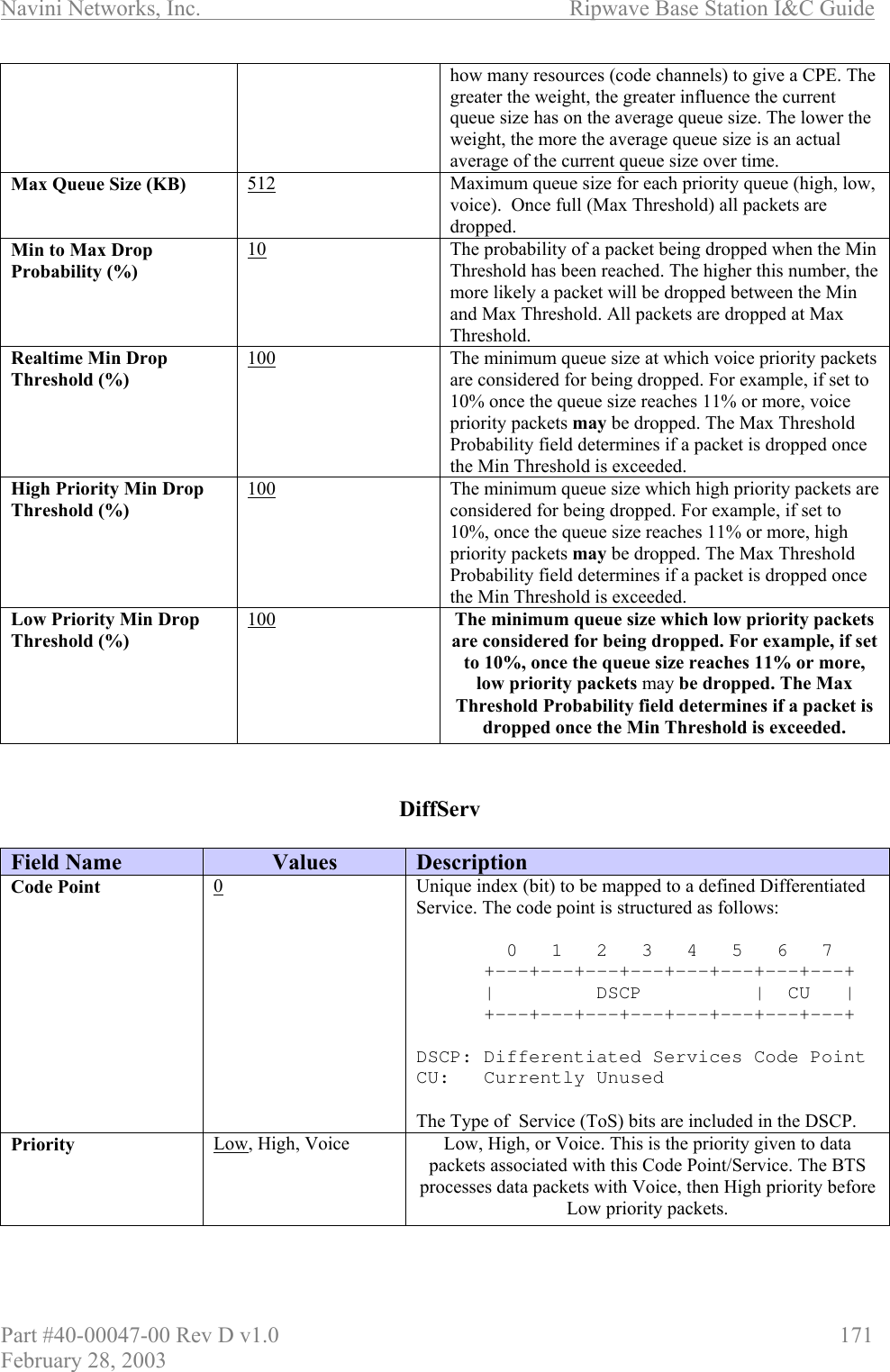
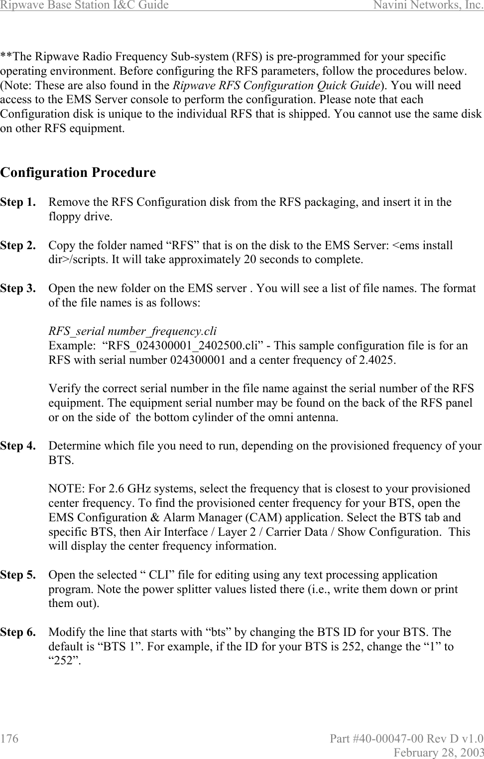
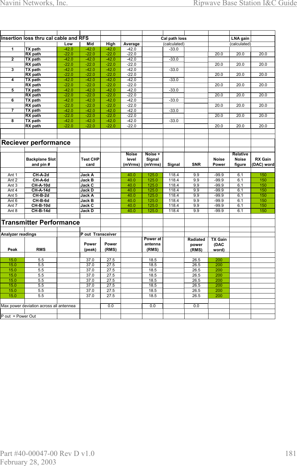
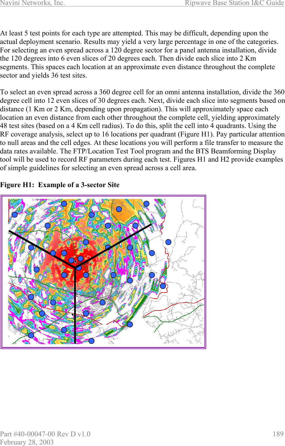
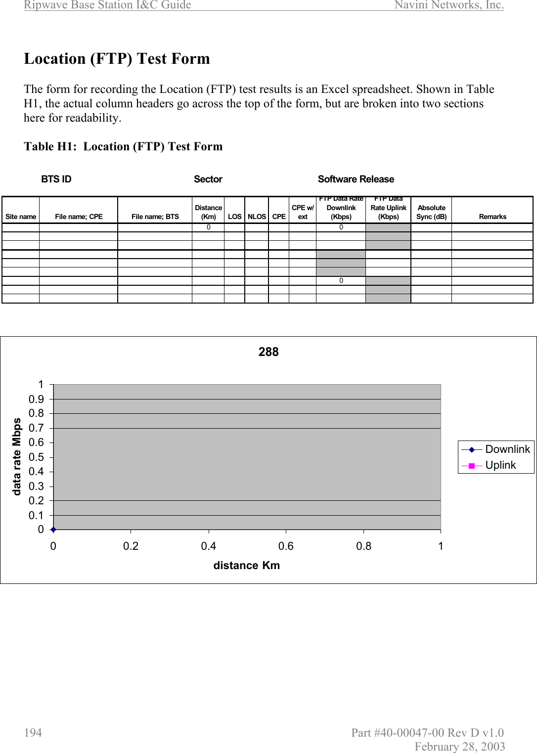
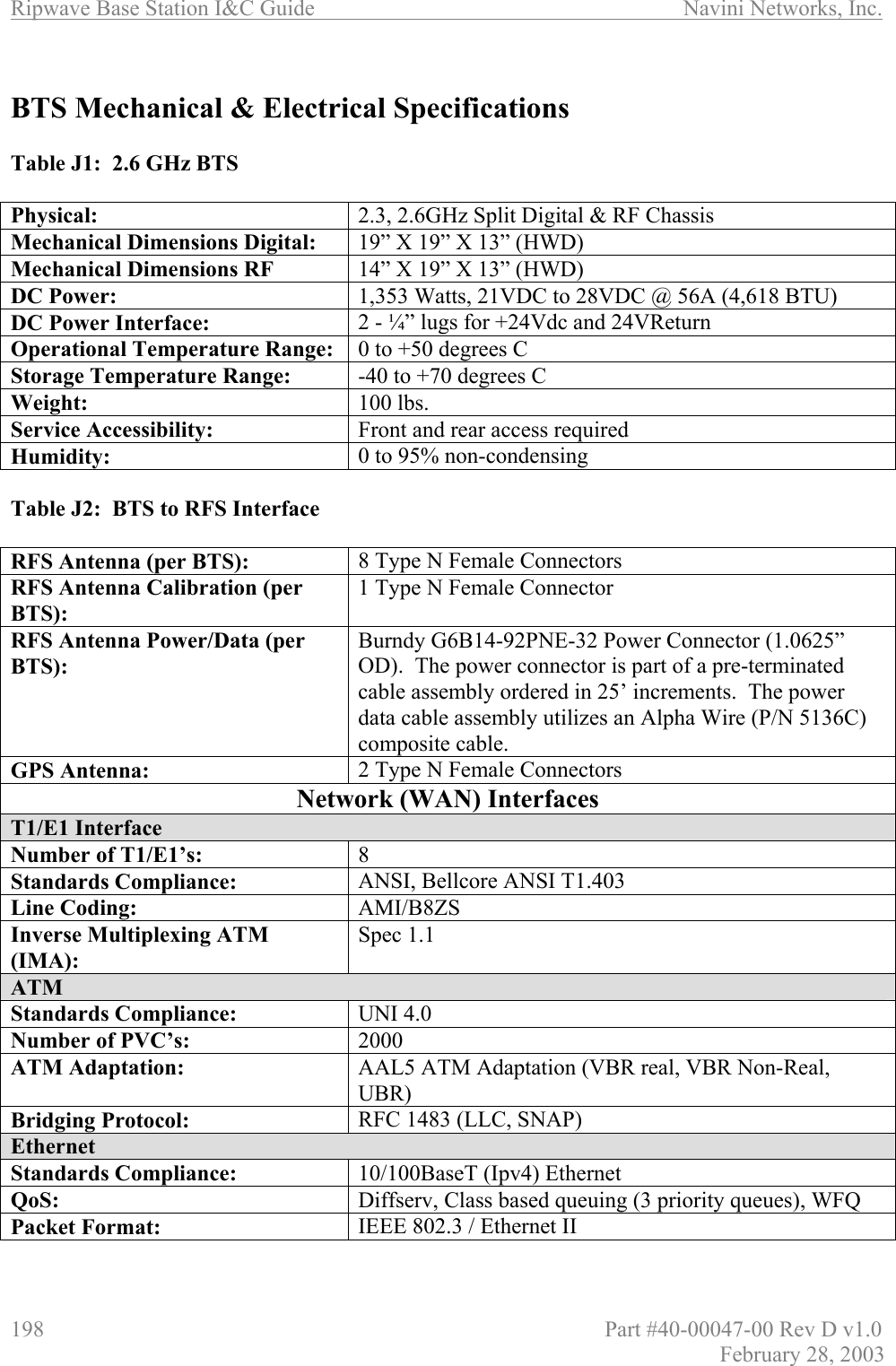
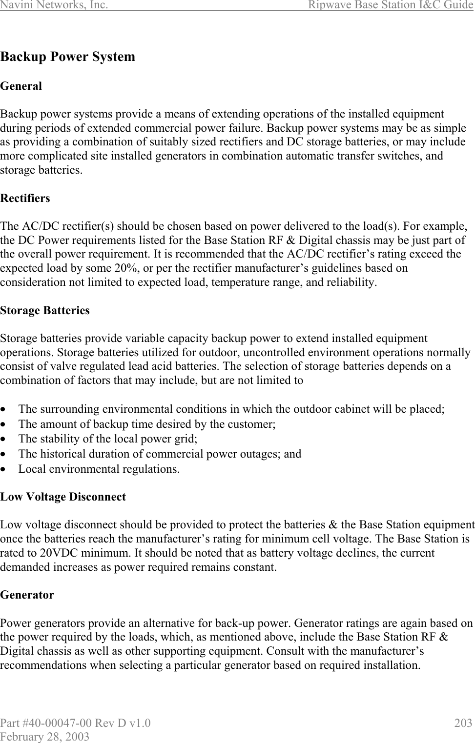
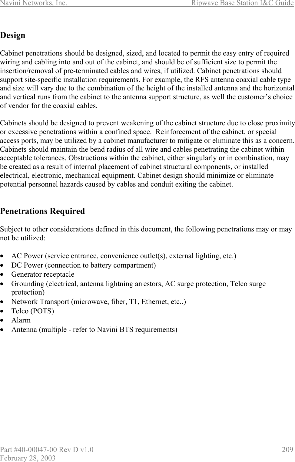
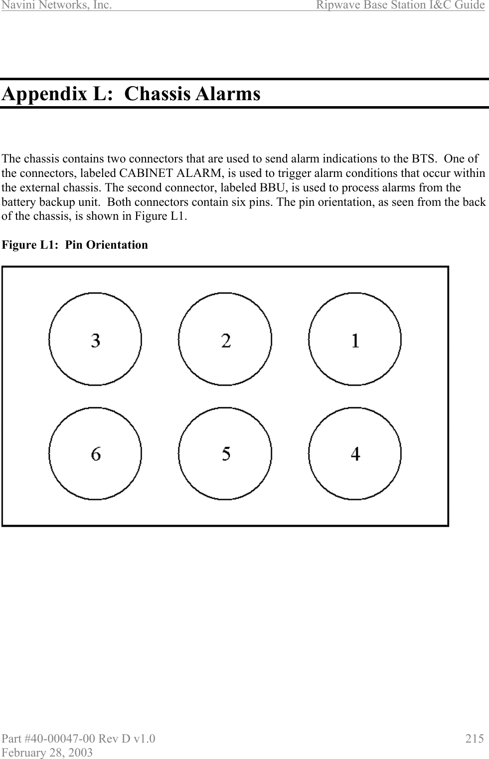
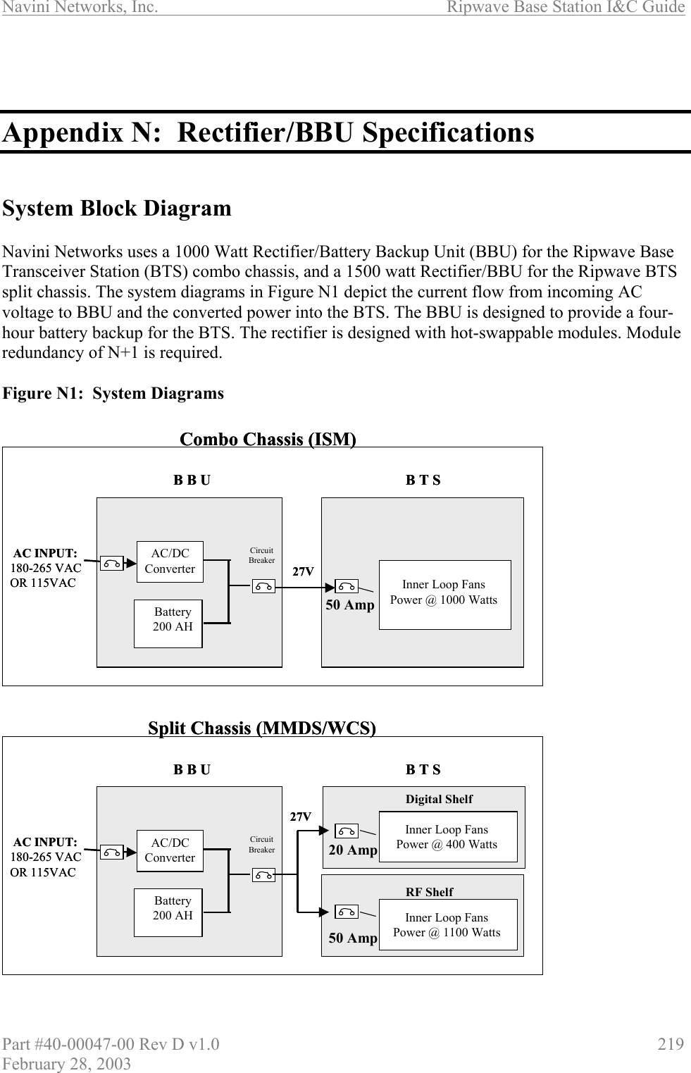
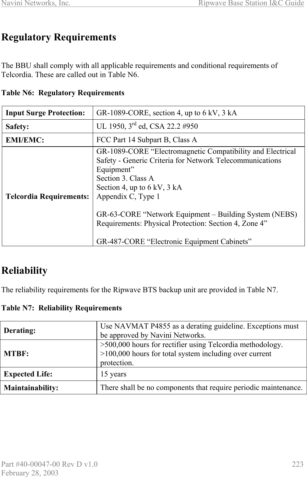
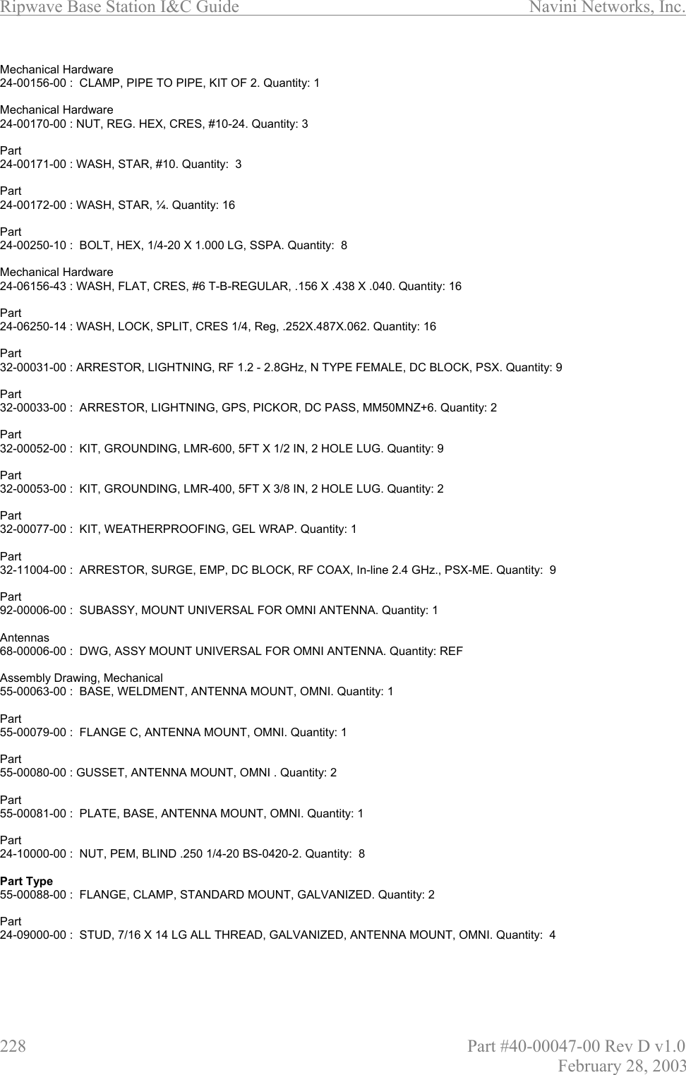
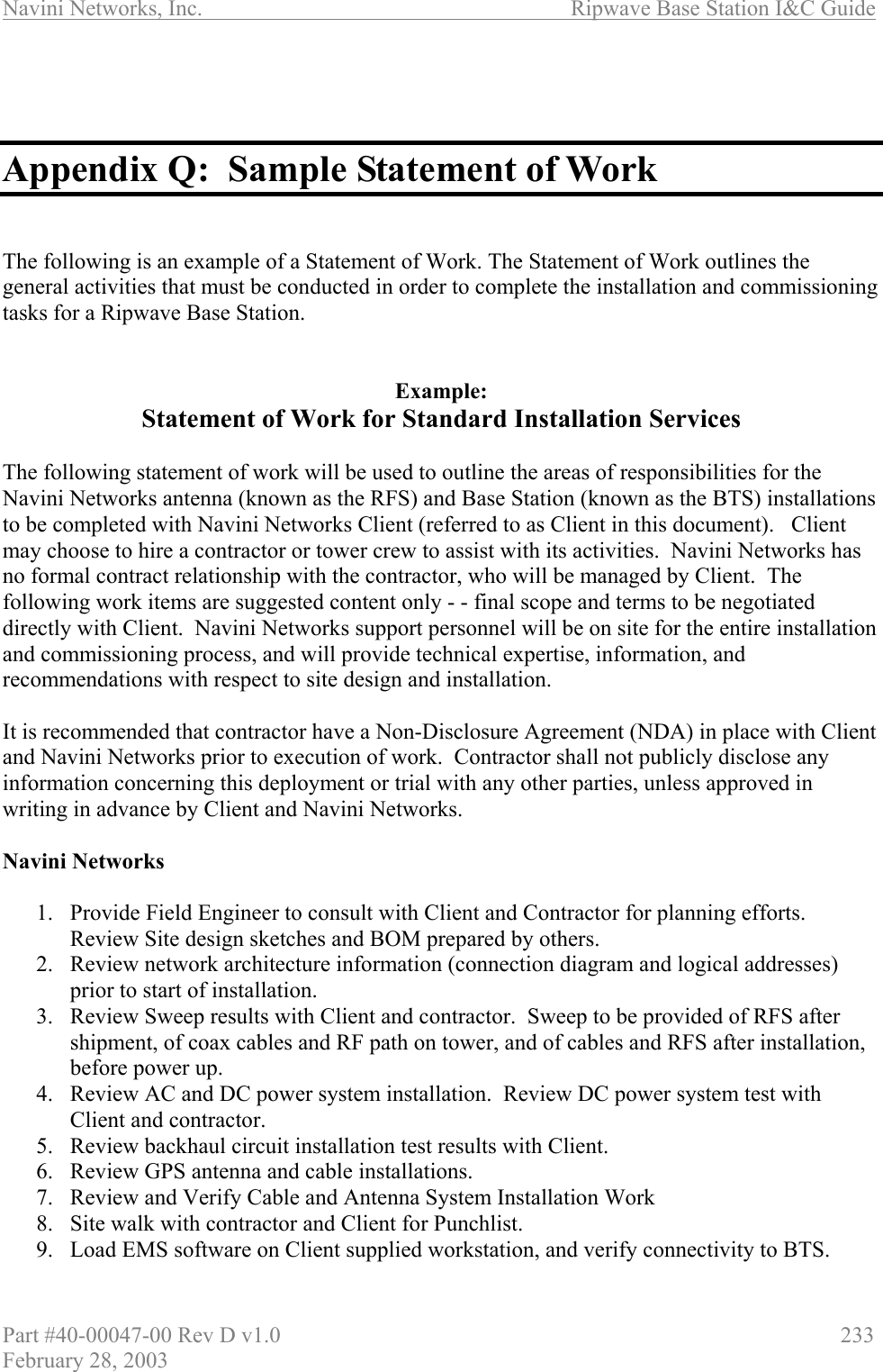
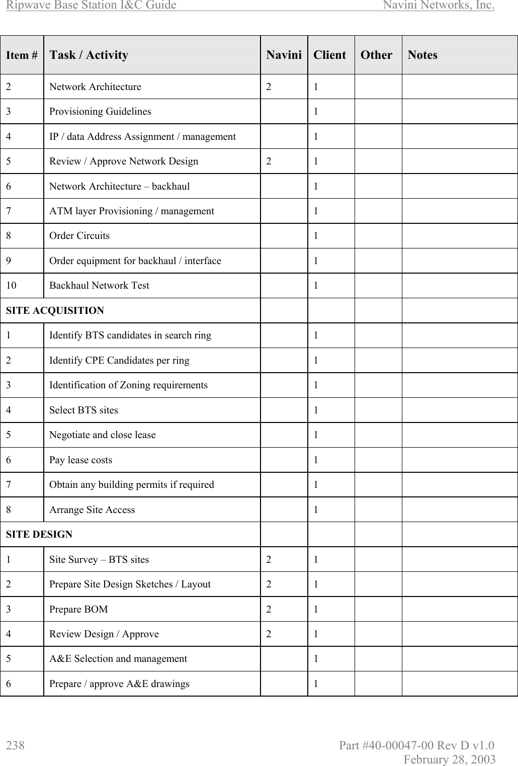
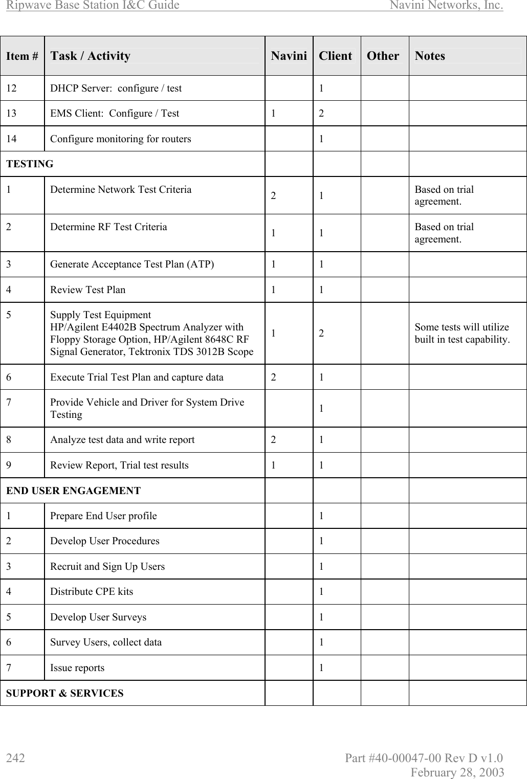
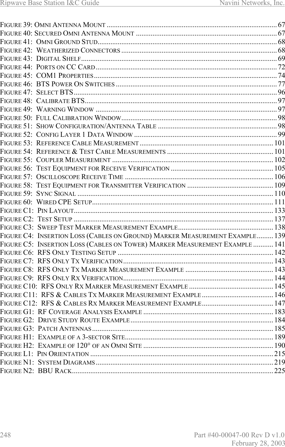
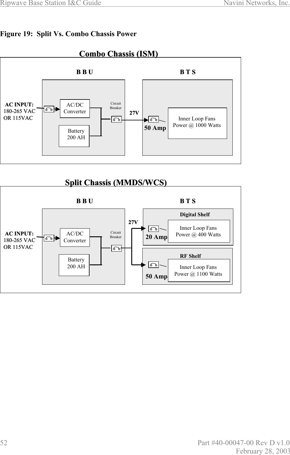
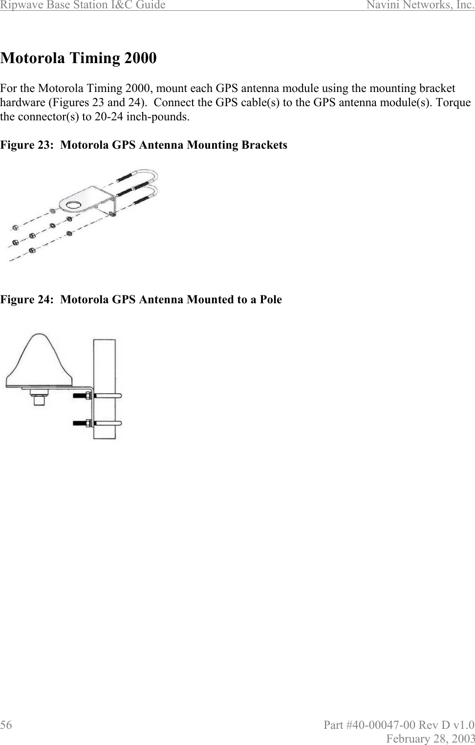
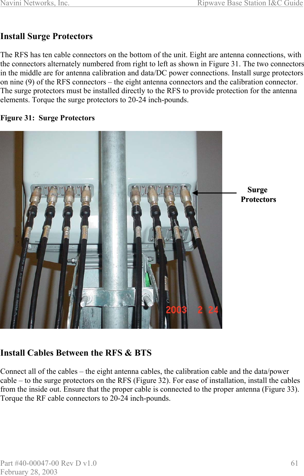
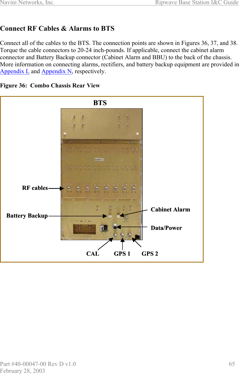
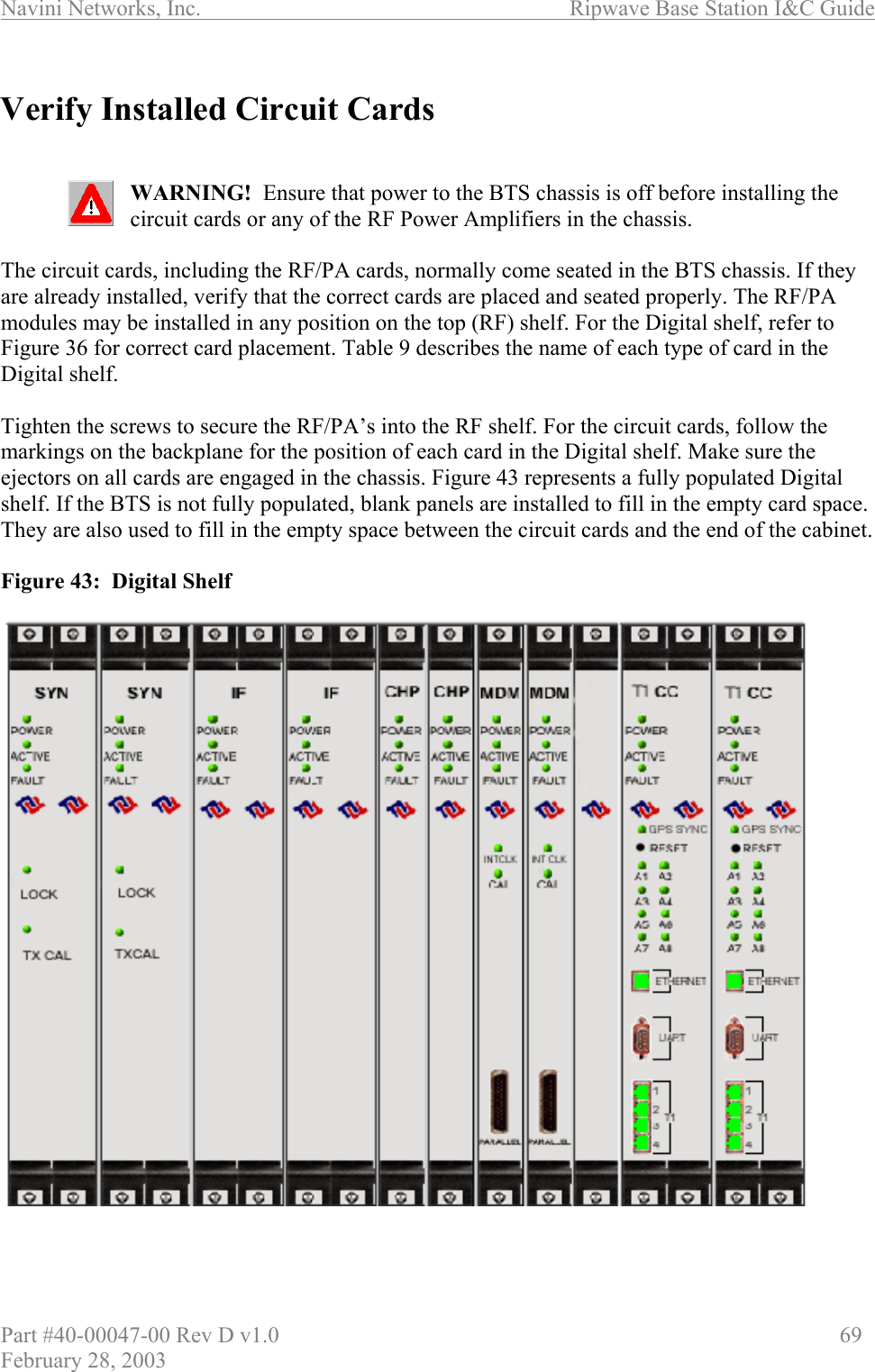
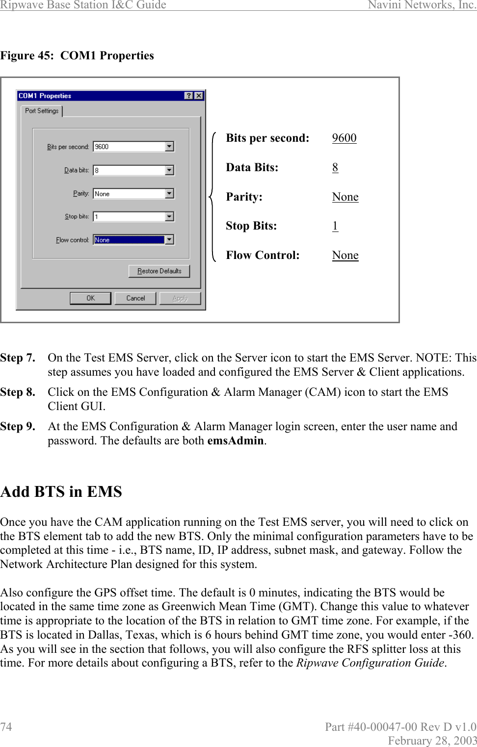
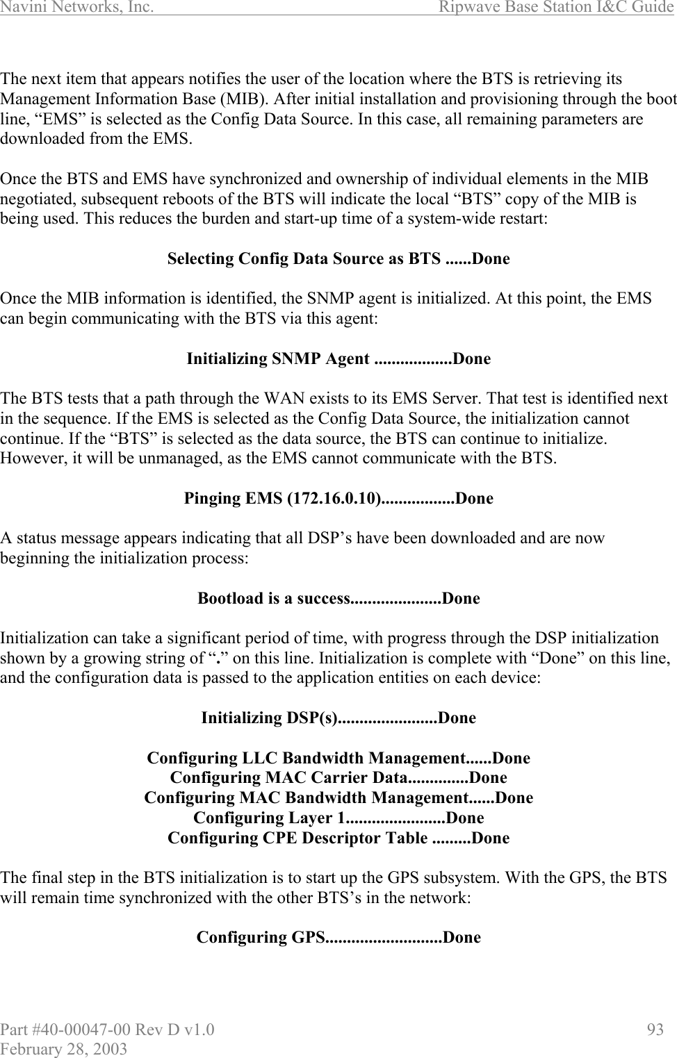
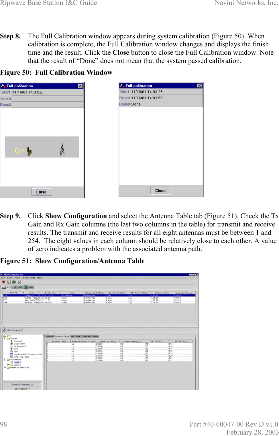
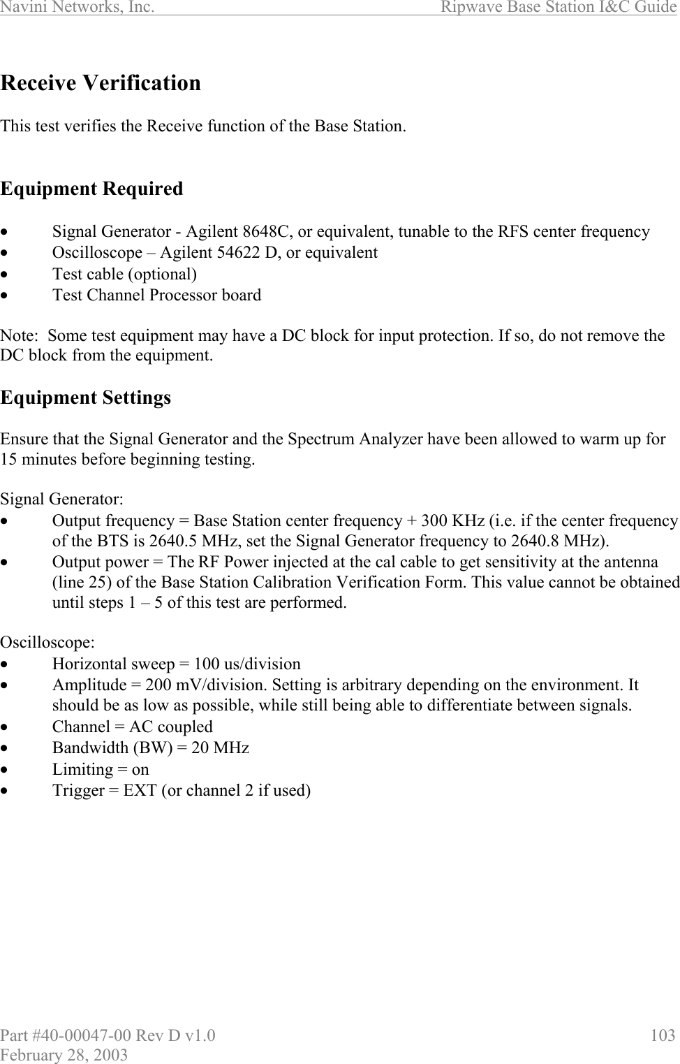
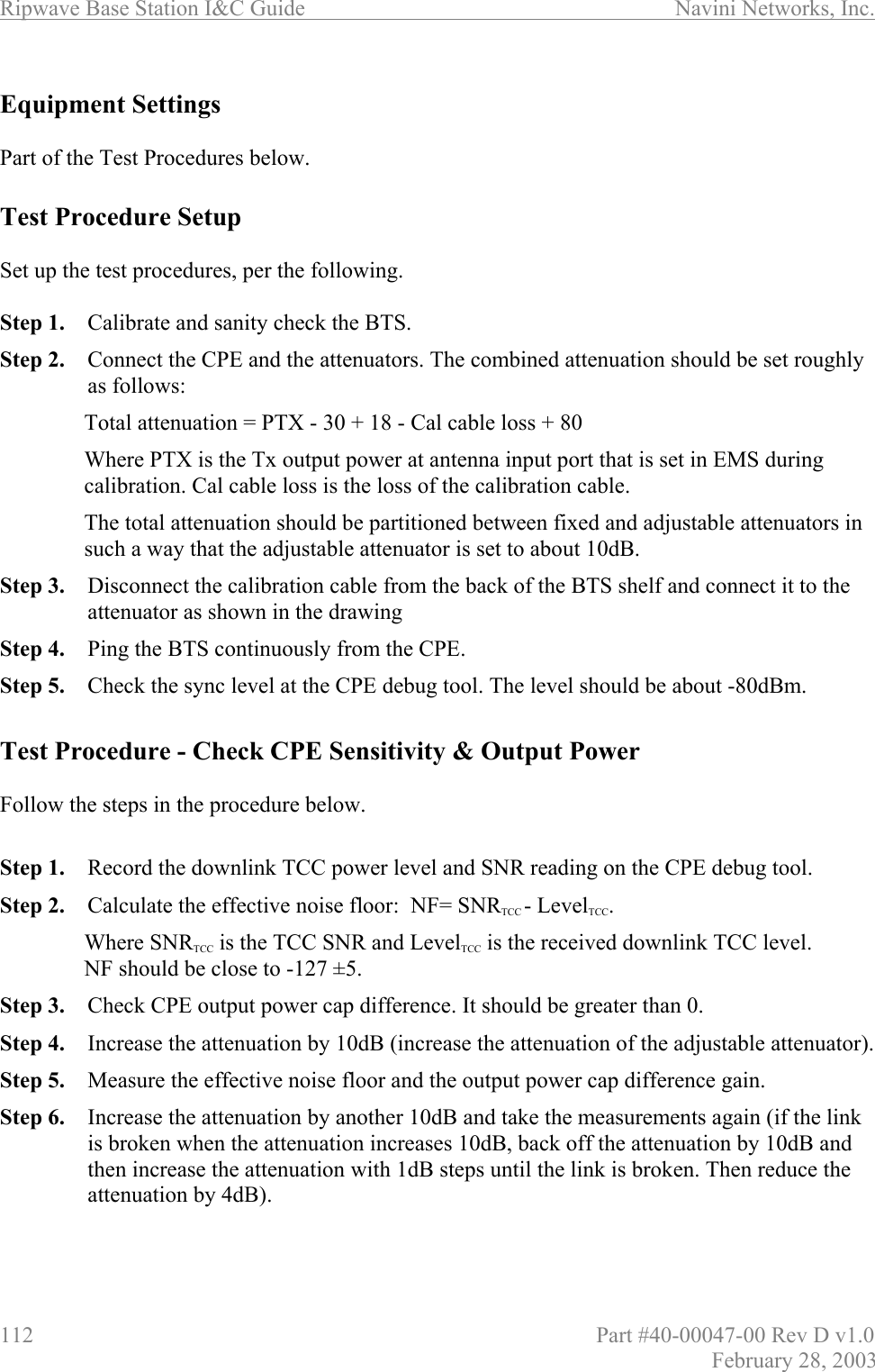
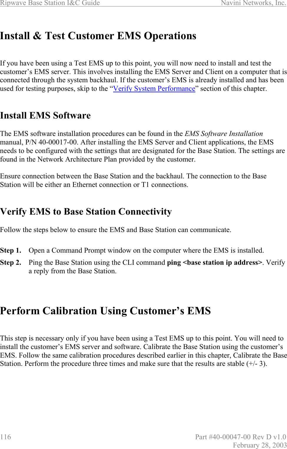
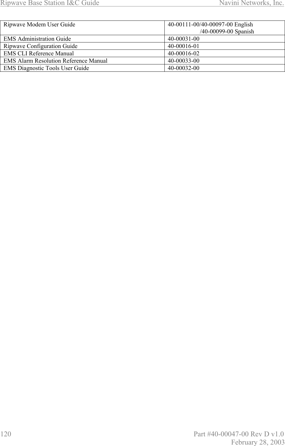
![Navini Networks, Inc. Ripwave Base Station I&C Guide Part #40-00047-00 Rev D v1.0 79 February 28, 2003 f – Fill memory allows you to alter portions of the BTS’s memory with a fixed pattern. It should only be performed with the assistance of a certified Navini service technician. t – Fill memory allows you to alter portions of the BTS’s memory with a pattern from another area of memory. It should only be performed with the assistance of a certified Navini service technician. Ethernet Configuration The Ethernet configuration is grouped into three sections: general, EMS, and traffic path. An example of the Ethernet configuration parameters is shown in Exhibit 2. Exhibit 2: Ethernet Configuration [Navini Boot]: pdate and time:01/09/2003[10:19] MM/dd/yyyy[hh:mm]autoboot countdown:delayed [quick|delayed]ems inet:172.16.0.10snmp community:publictraffic path:enet [enet|atm]mac address:00:04:6a:00:01:20ip on enet (active) : 172.16.23.181ip on enet (standby) : 172.16.23.182netmask on enet:255.255.0.0ip on backplane:10.0.0.1gateway on enet :172.16.0.100 General The general section offers you the ability to change the date and time manually. If a GPS has been installed, the BTS will automatically set the date and time: date and time : 08/21/2002[13:21] MM/dd/yyyy[hh:mm] When this line is displayed, the current date (08/21/2002) and time [13:21] are displayed. Accept the defaults by pressing the Enter key, or enter “date” at the console and a new value using the format indicated in military time (Hours 1-24). All 5 fields must be entered as specified. Leading zeroes can be omitted. Previously, it was mentioned that the 20-second auto-boot countdown timer can be disabled and a 1 second countdown can be used instead. To enable this feature, change the autoboot countdown item from “delayed” (which is 20 seconds) to “quick”, which is 1 second: autoboot countdown : delayed [quick|delayed]](https://usermanual.wiki/Cisco-Systems/ISM-BTS-R1.Users-Manual-Section2/User-Guide-387217-Page-30.png)
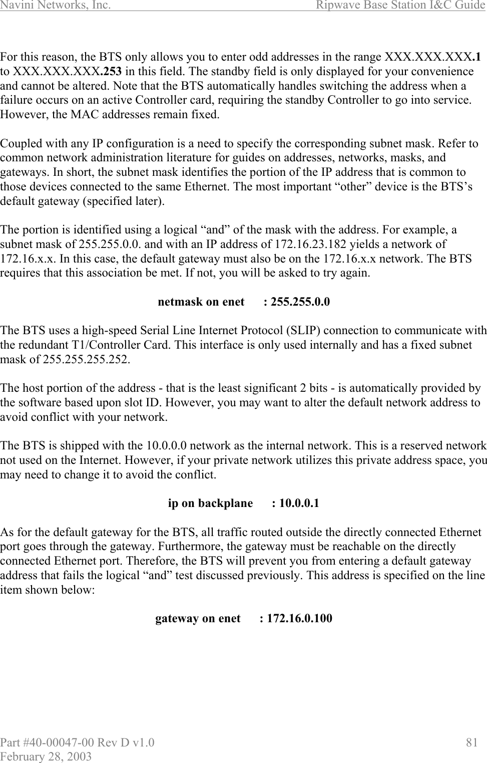
![Ripwave Base Station I&C Guide Navini Networks, Inc. 80 Part #40-00047-00 Rev D v1.0 February 28, 2003 EMS This section concerns the configuration of the EMS Server itself. First, the Internet (inet) IP address of the Server is specified. Make sure to fill this field with the address of the Server used to configure this BTS. Your BTS is shipped with this field un-initialized. You must provide a valid 4-digit IP address before you can proceed. For example: ems inet : 172.16.0.10 The second parameter that you must specify to allow the EMS Server to recognize this BTS is a community string for the EMS’s Simple Network Management Protocol (SNMP) interface. The default community string shipped with the BTS is “public”. Press the Enter key to accept this default, or type in a new value and press the Enter key to alter it: snmp community : public Traffic Path The last major block of configurations required for an Ethernet backhaul to the BTS is the traffic path parameters. The first prompt instructs the BTS to use the Ethernet as the WAN (backhaul) configuration. It must be set to “enet” for an Ethernet backhaul. If “atm” is selected, proceed with the description in the ATM or IMA sections. The BTS is pre-configured to use Ethernet for the WAN connection. Press the Enter key to accept this default: traffic path : enet [enet|atm] The BTS address is specified next. Every BTS must be uniquely addressed and have values that equate in the EMS configurations. This address information defines the Layer 2 parameters first, and then it defines the Layer 3 parameters. For Layer 2, you are only given an opportunity to see the Ethernet Media Access Control (MAC) address used by this BTS. This is a unique number programmed in the BTS. You cannot alter it. However, situations may develop in which you need to know the MAC address and, therefore, need to display the information. For example: mac address : 00:04:6a:00:01:20 Next are the IP addresses that represent this BTS: one for the active CC card and one for the standby CC card. The active Controller card is always addressed using an odd-numbered IP address, i.e., 172.16.23.181. The standby Controller card uses the corresponding even-numbered IP address one digit higher, i.e., 172.16.23.182. ip on enet (active) : 172.16.23.181 ip on enet (standby) : 172.16.23.182](https://usermanual.wiki/Cisco-Systems/ISM-BTS-R1.Users-Manual-Section2/User-Guide-387217-Page-31.png)
![Ripwave Base Station I&C Guide Navini Networks, Inc. 82 Part #40-00047-00 Rev D v1.0 February 28, 2003 ATM/T1 Configuration For an ATM/T1 configuration, the items shown in Exhibit 3 are identical to Ethernet with the exception of the traffic path, which must show “atm” for this type of configuration. Exhibit 3: ATM/T1 Configuration date and time:01/09/2003[10:22]autoboot countdown:delayedems inet:172.16.0.10snmp community:publictraffic path:atmmac address:00:04:6a:00:01:20ip on atm (active) : 172.16.23.181ip on atm (standby) : 172.16.23.182netmask on atm:255.255.0.0 When ATM is selected for the WAN interface using the traffic mode parameter, an additional set of parameters is required (Exhibit 6). First of all, another IP address must be identified for the ATM interface. The ATM IP address cannot be the same as the Ethernet IP address. In this case, the Ethernet IP address is only used for debug purposes and is a non-routed interface. This means that the BTS can only reach other computers directly connected to the Ethernet port of the BTS. The only routed interface available is through the ATM port. This routed interface address is specified with the “ip on atm” line item and the corresponding netmask parameter (Exhibit 4). The information on network address specifications from the Ethernet Configuration section of this chapter applies to ATM as well. For ATM, the only gateway allowed for the BTS is on the ATM interface, as specified here. Exhibit 4: Additional ATM Parameters ip on atm (active):172.17.0.101ip on atm (standby) : 172.17.0.102netmask on atm:255.255.0.0ip on backplane:10.0.0.1gateway on atm:172.17.0.100 For an ATM system, the BTS must have some additional configuration for the Management Private Virtual Channel (Management PVC). Recall the boot parameter philosophy discussed before. The boot parameters only identify those settings required to allow the BTS to reach the EMS. Note that the boot parameters only allow specification for one PVC (the Management PVC), which is used to reach the EMS. All user traffic PVC parameters are specified in the EMS configuration. Ensure that the EMS parameters for the Management PVC match those being set here through the boot prompt. If not, as soon as connection is made with the EMS, the Management PVC will be reconfigured and can potentially disconnect the BTS from the network.](https://usermanual.wiki/Cisco-Systems/ISM-BTS-R1.Users-Manual-Section2/User-Guide-387217-Page-33.png)
![Navini Networks, Inc. Ripwave Base Station I&C Guide Part #40-00047-00 Rev D v1.0 83 February 28, 2003 The PVC configuration is broken into 3 sections: ATM layer parameters; optional Inverse Multiplexing over ATM (IMA) parameters, and T1 physical layer parameters. The first item selects which ATM interface will be used for the Management PVC. If IMA is not selected, you may select from one of the 8 T1 ports numbered 1-8 using the option t1-N, where N is the port number. This is the same interface port number specified in the EMS. If IMA is desired, reference the following section: pvc type-atm i/f : t1-0 [t1-(1-8)|ima-(1-2)] The circuit identifier for this segment of the Management PVC is the next item specified. The first parameter identifies the maximum number of bits for any PVC’s identifier Virtual Path Identifier/ Virtual Channel Identifier (VPI/VCI) pair. The BTS restricts the available set to 13 total bits. However, you are free to divide those 13 bits between the VPI and VCI as needed, with the VPI having a maximum allocation of 8 bits. You can choose the number of bits for each by selecting two values separated by a “:”. Or you may select the BTS default of 3 VPI bits and 10 VCI bits by pressing the Enter key: pvc id size vpi:vci : 3:10 [1-8:1-13] Having specified the number of significant VPI and VCI bits, now select the actual identifier. The BTS will restrict the values entered for the VPI and VCI to the ranges you selected in the previous size specification. For instance, if 3:10 is selected as a size allocation, the VPI must be between 0 and 7. Again, you can select the values for the VPI and VCI separated by a “:” or accept the default value of VPI = 1 and VCI = 100 by pressing the Enter key. Be careful not to use the reserved VCI values from 0-15 that are often used in ATM networks for Operation, Administration, and Maintenance (OAM) purposes. pvc vpi:vci : 1:100 [0-255:16-8192] The service category for the Management PVC is specified next. The choices are Unspecified Bit Rate (UBR) or Constant Bit Rate (CBR). Other ATM service categories are available for traffic PVC’s, but those are specified in the EMS configuration. UBR and CBR both require a set data rate and delay variation parameter. The data rate is specified in cells per second in the ATM Traffic Contract’s Peak Cell Rate (PCR) field. The delay variation is in the ATM Cell Delay Variation Tolerance (CDVT) in the ATC’s CDVT field. Specify the PCR and the CDVT values separated by a “:” or chose the default by pressing the Enter key. pvc service category : ubr [cbr|ubr] pvc atc pcr:cdvt : 3641:100 [1-3641:0-100]](https://usermanual.wiki/Cisco-Systems/ISM-BTS-R1.Users-Manual-Section2/User-Guide-387217-Page-34.png)
![Ripwave Base Station I&C Guide Navini Networks, Inc. 84 Part #40-00047-00 Rev D v1.0 February 28, 2003 The final set of values is used to configure the T1 parameters. The line type allows you to select Extended Super-Frame (ESF) or D4. ESF format is the standard format for ATM/T1 applications. D4 format is supported as an alternate; however, T1 signaling capabilities may be limited. Check your network plans for a definition for your specific application. line type : esf [esf|d4] Additionally, you must choose a line coding type: line coding : b8zs [b8zs|ami] The approximate length of the T1 line is specified next. It is used to control the signal conditioning used on the T1: line length (ft) : 500 Finally, the T1’s timing source must be specified. A T1 uses only one timing source either at the near-end or far-end of the line. You may select the BTS as the originator of the timing source by selecting “local”, or you may select the far-end as the timing reference by selecting “loop”. line clock source : loop [loop|local] IMA Configuration If you decide to utilize IMA groups to pool the T1 resources, then the same parameters described for the ATM/T1 Configuration above also apply to configuring IMA’s. Refer to Exhibit 5. Exhibit 5: IMA Configuration date and time:08/21/2001[10:22]ems inet:172.16.0.10snmp community:publictraffic path:atmmac address:00:04:6a:00:01:20ip on enet (active) : 172.16.23.181ip on enet (standby) : 172.16.23.182netmask on enet:255.255.0.0ip on atm (active):172.17.0.101ip on atm (standby) : 172.17.0.102netmask on atm:255.255.0.0ip on backplane:10.0.0.1gateway on atm:172.17.0.100 In addition, the ATM interface must be specified as IMA and reference one of two IMA groups used for the Management PVC. This IMA group must match what is identified in the EMS. Use “0” for the first group and “1” for the second group.](https://usermanual.wiki/Cisco-Systems/ISM-BTS-R1.Users-Manual-Section2/User-Guide-387217-Page-35.png)
![Navini Networks, Inc. Ripwave Base Station I&C Guide Part #40-00047-00 Rev D v1.0 85 February 28, 2003 Each group identifies a set of T1 ports that are being combined to form one larger virtual port. For the sake of boot parameter specification, ALL T1 interfaces for the Management PVC’s IMA group are assumed to be identical. So the parameters for T1 specifications apply to all T1’s of the IMA group: pvc type-atm i/f : ima-0 Once the IMA interface is selected, a set of IMA parameters must be specified for the IMA group used by the Management PVC. An IMA group inherently supports dynamic addition and drops of individual T1 facilities from the group to facilitate fault tolerance to failed T1 facilities. The minimum number of T1 ports, or links, that must exist for the IMA group to function is specified here. A value from 1-7 is required for each of the receive and transmit directions. Separate the values with “:”. You can increase the values from the default of 1 link in each direction or accept the default by pressing the Enter key. ima min rx:tx links : 1:1 [1-7:1-7] Next, specify which T1 ports are used to form the IMA group. This is a list of T1 port identifiers (1-8), each separated by commas. The BTS makes sure you enter at least as many links as you specified for the minimum requirements above: selected ima links : 1,2,3,4,5,6,7,8 The near- and far-end IMA protocols use an ID number to identify each other. This value must agree with that provisioned at the far-end of the IMA link. The BTS defaults to a value of 0, but you can specify any value from 0 to 255: ima group id : 0 [0-255] Group symmetry modes allow symmetric or asymmetric operation of IMA links: ima symmetry : sym [sym|asym|asym-cfg] IMA frame length specifies the size of the IMA frames that are being transmitted: ima frame length : 128 [32|64|128] The IMA alpha/beta/gamma parameters are used by the IMA frame synchronization mechanism.: ima alpha:beta:gamma : 2:2:1 [1-2:1-5:1-5] The IMA clock mode selects either a common or independent IMA clock mode (Exhibit 6). It is the same as for ATM/T1.](https://usermanual.wiki/Cisco-Systems/ISM-BTS-R1.Users-Manual-Section2/User-Guide-387217-Page-36.png)
![Ripwave Base Station I&C Guide Navini Networks, Inc. 86 Part #40-00047-00 Rev D v1.0 February 28, 2003 Exhibit 6: IMA Clock Mode ima clock mode:ctc [ctc|itc]pvc id size vpi:vci : 3:10pvc vpi:vci:1:100pvc service category : ubrpvc atc pcr:cdvt:3641:100line type:esfline coding:b8zsline length (ft):500line clock source:loop Standard Boot Sequence The first items in Exhibit 7 (Ethernet) and Exhibit 8 (ATM) illustrate the BOOTROM loading and launching of the core application. This is a fixed process that cannot be altered in the field. Auto-booting is the process that can be escaped by user intervention, (i.e., enter “config”), in order to enter the boot prompt. Without user intervention, the remaining sequence occurs automatically; hence, “auto-boot”. Exhibit 7: Standard Ethernet Boot Sequence - Example System BootCopyright 2000-2001 Navini Networks, Inc.Copyright 1984-1998 Wind River Systems, Inc.CPU: CC (PPC860P)Kernel Version: 5.4BSP version: 1.0/110501Creation date: Nov 5 2001, 13:09:12Attaching to TFFS... done.Loading /tffs0/LOADS/BTSA/core...5249740Starting at 0x10000...Auto-booting..............................DoneStarting File System......................DoneMounting Drive /tffs0.....................DoneMounting Drive /dev0......................DoneMounting Drive /dev1......................DoneStarting TCP/IP Stack.....................DoneStarting ARP..............................DoneStarting motfec I/f.......................DoneAttaching sl(0) I/f.......................DoneAttaching motfec(0) I/f...................DoneAttaching lo(0) I/f.......................DoneMounting Remote Filesystem................DoneStarting Telnet Daemon....................DoneStarting Load Monitoring Tools............DoneLoading Target Shell Symbols..............DoneStarting WDB Tools........................DoneStarting Target Shell.....................DoneInitializing System Logger................DoneStarting Application......................DoneStarting LLC I/f..........................DoneStarting LLC Proxy........................DoneStarting Lpbk Proxy.......................Done](https://usermanual.wiki/Cisco-Systems/ISM-BTS-R1.Users-Manual-Section2/User-Guide-387217-Page-37.png)
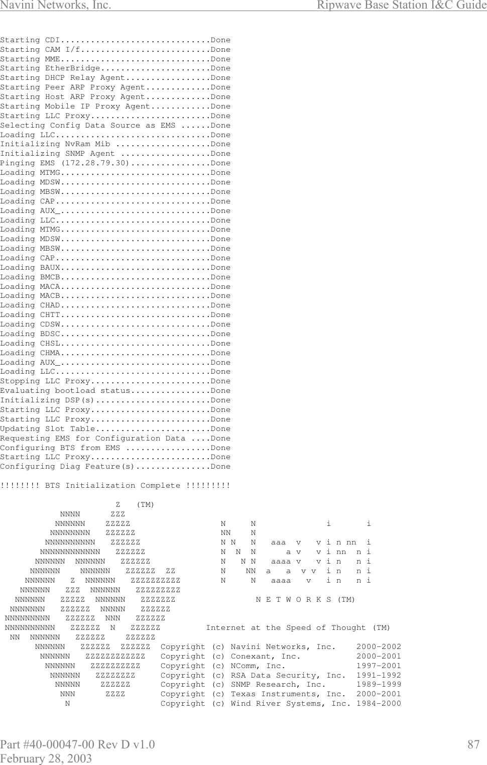
![Ripwave Base Station I&C Guide Navini Networks, Inc. 88 Part #40-00047-00 Rev D v1.0 February 28, 2003 KERNEL : 5.4(WIND version 2.5)BSP:1.0/01.19.00.00CPU: CC (PPC860P). Processor #0.Memory Size: 0x3f80000.WDB: Ready.Last reset caused by a power on condition.Current time is FRI JUL 12 14:48:29 2002bts-4 [Active]% Exhibit 8: Standard ATM Boot Sequence - Example System BootCopyright 2000-2001 Navini Networks, Inc.Copyright 1984-1998 Wind River Systems, Inc.CPU: CC (PPC860P)Kernel Version: 5.4BSP version: 1.0/110501Creation date: Nov 5 2001, 13:09:12Attaching to TFFS... done.Loading /tffs0/LOADS/BTSB/core...5249740Starting at 0x10000...Auto-booting..............................DoneStarting File System......................DoneMounting Drive /tffs0.....................DoneMounting Drive /dev0......................DoneMounting Drive /dev1......................DoneStarting TCP/IP Stack.....................DoneStarting ARP..............................DoneStarting motfec I/f.......................DoneStarting wec I/f..........................DoneAttaching wec(0) I/f......................DoneAttaching sl(0) I/f.......................DoneAttaching motfec(0) I/f...................DoneAttaching lo(0) I/f.......................DoneMounting Remote Filesystem................DoneStarting Telnet Daemon....................DoneStarting Load Monitoring Tools............DoneLoading Target Shell Symbols..............DoneStarting WDB Tools........................DoneStarting Target Shell.....................DoneInitializing System Logger................DoneStarting Application......................DoneStarting LLC I/f..........................DoneStarting LLC Proxy........................DoneStarting Lpbk Proxy.......................DoneStarting CDI..............................DoneInclude CME Starting T1 I/f...............DoneStarting CAM I/f..........................DoneStarting MME..............................DoneStarting EtherBridge......................DoneStarting DHCP Relay Agent.................DoneStarting Peer ARP Proxy Agent.............DoneStarting Host ARP Proxy Agent.............DoneStarting Mobile IP Proxy Agent............DoneStarting PCI Bridge.......................DoneStarting Network Processor................DoneStarting LLC Proxy........................DoneLoading LLC...............................DoneSelecting Config Data Source as EMS ......DoneInitializing NvRam Mib ...................DoneBooting Network Processor ................DoneConfiguring T1(s).........................DoneConfiguring ATM Interface.................Done](https://usermanual.wiki/Cisco-Systems/ISM-BTS-R1.Users-Manual-Section2/User-Guide-387217-Page-39.png)
![Ripwave Base Station I&C Guide Navini Networks, Inc. 90 Part #40-00047-00 Rev D v1.0 February 28, 2003 Last reset caused by a power on condition.Current time is FRI JUL 12 14:26:59 2002bts-4 [Active]%Attaching to TFFS... done.Loading /tffs0/LOADS/BTSB/core... 4337576Starting at 0x10000...Auto-booting..............................Done The line items in Exhibit 9 are the ones that create and initialize the core components to the BTS’s on-board file system. This file system is used to store operating code images, configuration data, and log files. The BTS Operating System software handles the images, data, and files and does not require operator assistance. There are three on-board file systems’ FLASH and RAM drives. The FLASH drive is at /tffs0 and the two RAM drives use /dev0 and /dev1. All on-board file system drives have dedicated functions and should not be altered or used through manual operations. Exhibit 9: On-board File Systems Starting File System......................DoneMounting Drive /tffs0.....................DoneMounting Drive /dev0......................DoneMounting Drive /dev1......................Done The sequence shown in Exhibit 10 initializes the TCP/IP stack on the BTS. The TCP, UDP, IP, and ARP protocol stacks are created. Interfaces for the stack are then created and attached to the stack. Three or four interfaces are created depending on the selection for “traffic path” in the boot parameters. The Fast Ethernet Controller, fec (0), is created and attached for the 10/100 Ethernet ports on the BTS. If “atm” is selected, then a WAN Ethernet Controller, WEC (0), is also created and attached to the stack to perform RFC1483 Ethernet bridging onto the ATM interface. Internally, the BTS utilizes a high-speed SLIP interface, sl (0), to provide communication between redundant devices. Finally, a debug local loopback interface, lo (0), is created and attached. Exhibit 10: TCP/IP Stack Starting TCP/IP Stack.....................DoneStarting ARP..............................DoneStarting fec I/f..........................DoneStarting wec I/f..........................DoneAttaching wec(0) I/f......................DoneAttaching sl(0) I/f.......................DoneAttaching fec(0) I/f......................DoneAttaching lo(0) I/f.......................Done](https://usermanual.wiki/Cisco-Systems/ISM-BTS-R1.Users-Manual-Section2/User-Guide-387217-Page-41.png)
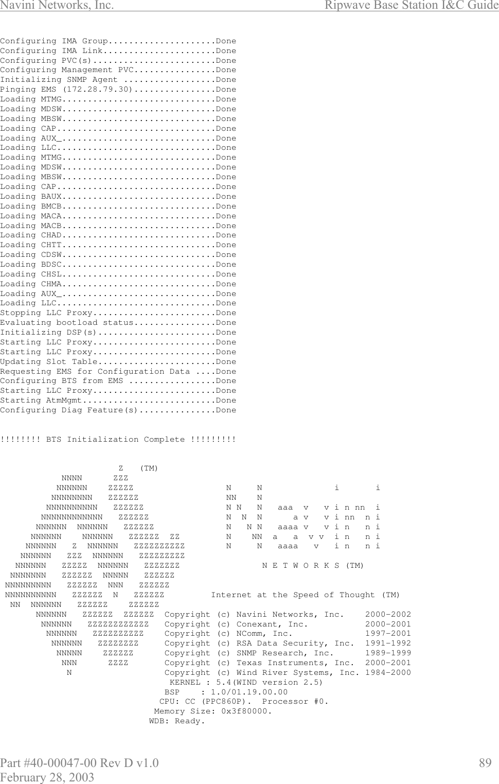
![Navini Networks, Inc. Ripwave Base Station I&C Guide Part #40-00047-00 Rev D v1.0 95 February 28, 2003 Loading CAP...............................DoneLoading BAUX..............................DoneLoading BMCB..............................DoneLoading MACA..............................DoneLoading MACB..............................DoneLoading CHAD..............................DoneLoading CHTT..............................DoneLoading CDSW..............................DoneLoading BDSC..............................DoneLoading CHSL..............................DoneLoading CHMA..............................DoneLoading AUX_..............................DoneLoading LLC...............................DoneStopping LLC Proxy........................DoneEvaluating bootload status................DoneInitializing DSP(s).......................DoneStarting LLC Proxy........................DoneStarting LLC Proxy........................DoneUpdating Slot Table.......................DoneConfiguring LLC Bandwidth Management......DoneConfiguring MAC Carrier Data..............DoneConfiguring MAC Bandwidth Management......DoneConfiguring Layer 1.......................DoneConfiguring CPE Descriptor Table .........DoneStarting LLC Proxy........................DoneConfiguring Diag Feature(s)...............DoneConfiguring GPS...........................Done!!!!!!!! BTS Initialization Complete !!!!!!!!!Z(TM)NNNNZZZNNNNNNZZZZZNNiiNNNNNNNN ZZZZZZNNNNNNNNNNNNN ZZZZZZNNNaaavvinnniNNNNNNNNNNNN ZZZZZZNNNavvinnniNNNNNN NNNNNN ZZZZZZNNNaaaa vvinniNNNNNNNNNNNN ZZZZZZ ZZNNNaavvinniNNNNNNZNNNNNN ZZZZZZZZZZNNaaaavinniNNNNNN ZZZ NNNNNN ZZZZZZZZZ NNNNNN ZZZZZ NNNNNN ZZZZZZZNETWORKS(TM) NNNNNNN ZZZZZZ NNNNN ZZZZZZ NNNNNNNNN ZZZZZZ NNN ZZZZZZ NNNNNNNNNN ZZZZZZ N ZZZZZZInternet at the Speed of Thought (TM) NN NNNNNN ZZZZZZZZZZZZNNNNNN ZZZZZZ ZZZZZZ Copyright(c)Navini Networks,Inc.2000-2002NNNNNN ZZZZZZZZZZZZ Copyright(c)Conexant,Inc. 2000-2001NNNNNN ZZZZZZZZZZ Copyright(c)Free Sw Foundation,Inc.1988-1999NNNNNN ZZZZZZZZ Copyright(c)NComm, Inc.1997-2001NNNNZZZZZZCopyright(c)RSA Data Security,Inc.1991-1992NNNZZZZCopyright(c)SNMP Research,Inc.1989-1999NZZCopyright(c)Texas Instruments,Inc.2000-2001Copyright(c)Wind River Systems,Inc.1984-2000KERNEL : 5.4(WIND version 2.5)BSP:1.0/RW1.19.1.3CPU: CC (PPC860P). Processor #0.Memory Size: 0x3f80000.WDB: Ready.Last reset caused by a user request from the console.Current time is FRI JAN 10 14:38:36 2003bts-120 [Active]% TimerHandler called for port /tty/2--> 1/10/2003 14:38:38Position fix: latitude: 32:58:42, longitude: -96:42:4, height: 188.78 ](https://usermanual.wiki/Cisco-Systems/ISM-BTS-R1.Users-Manual-Section2/User-Guide-387217-Page-46.png)
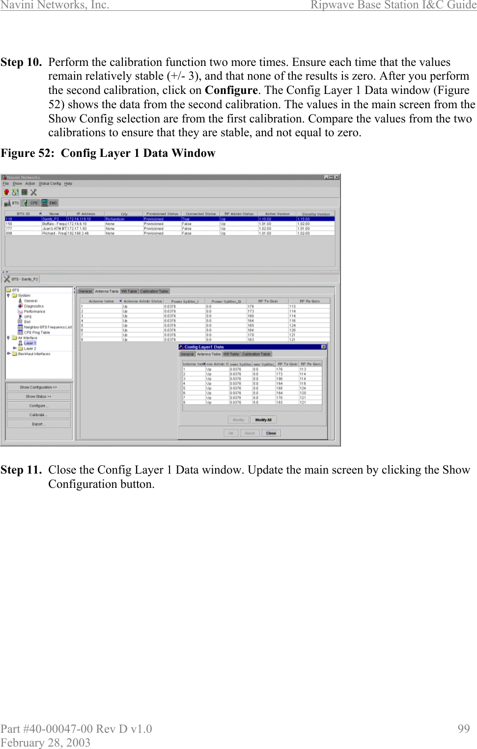

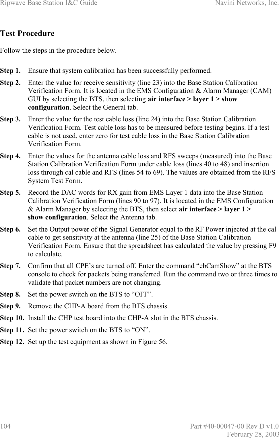

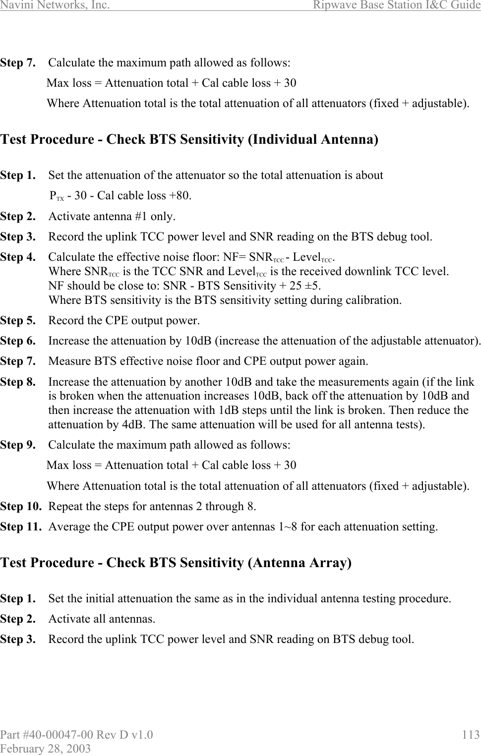
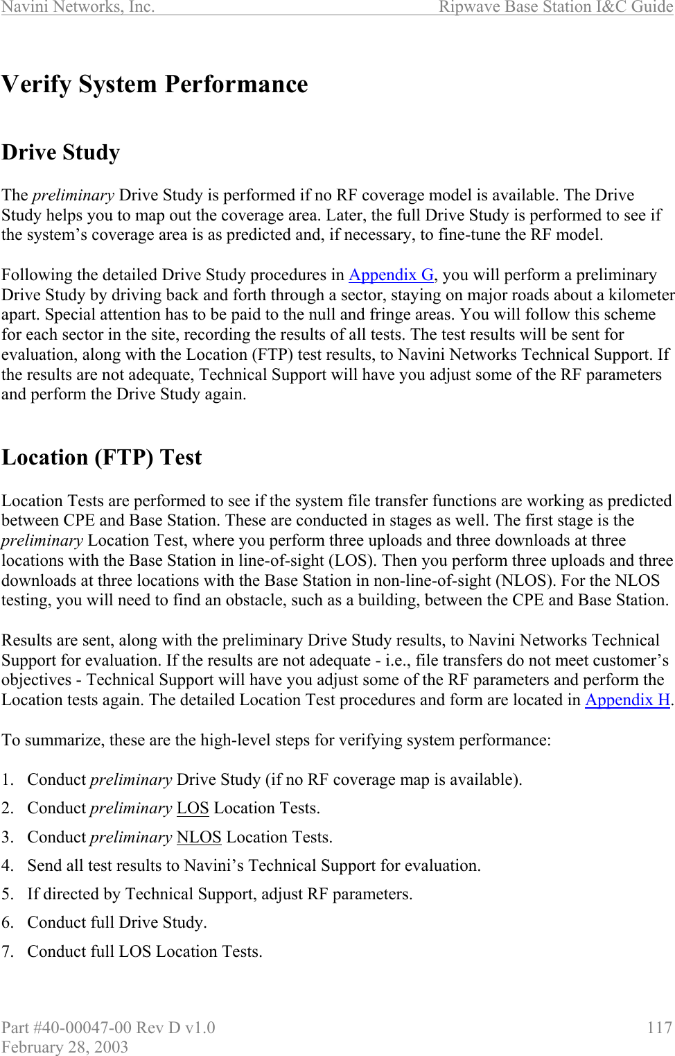

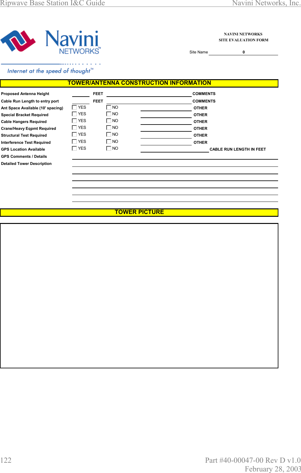


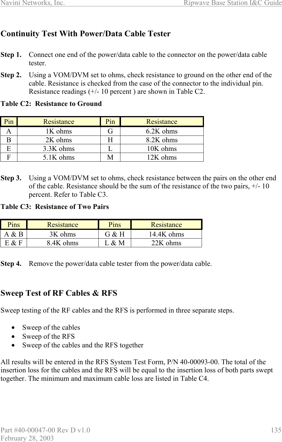
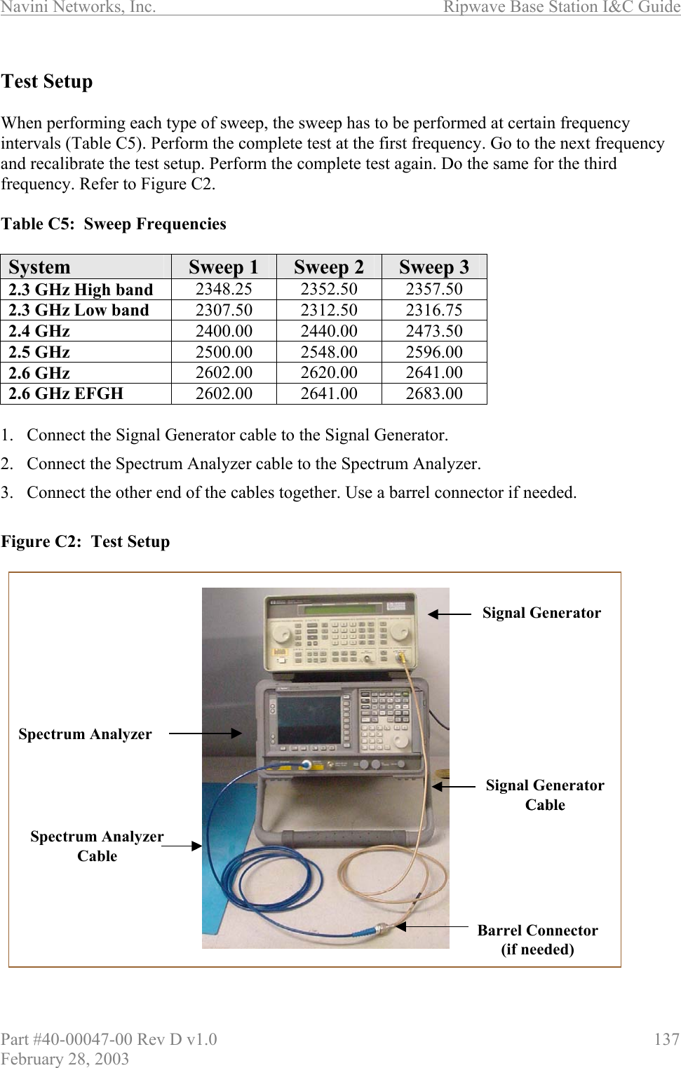
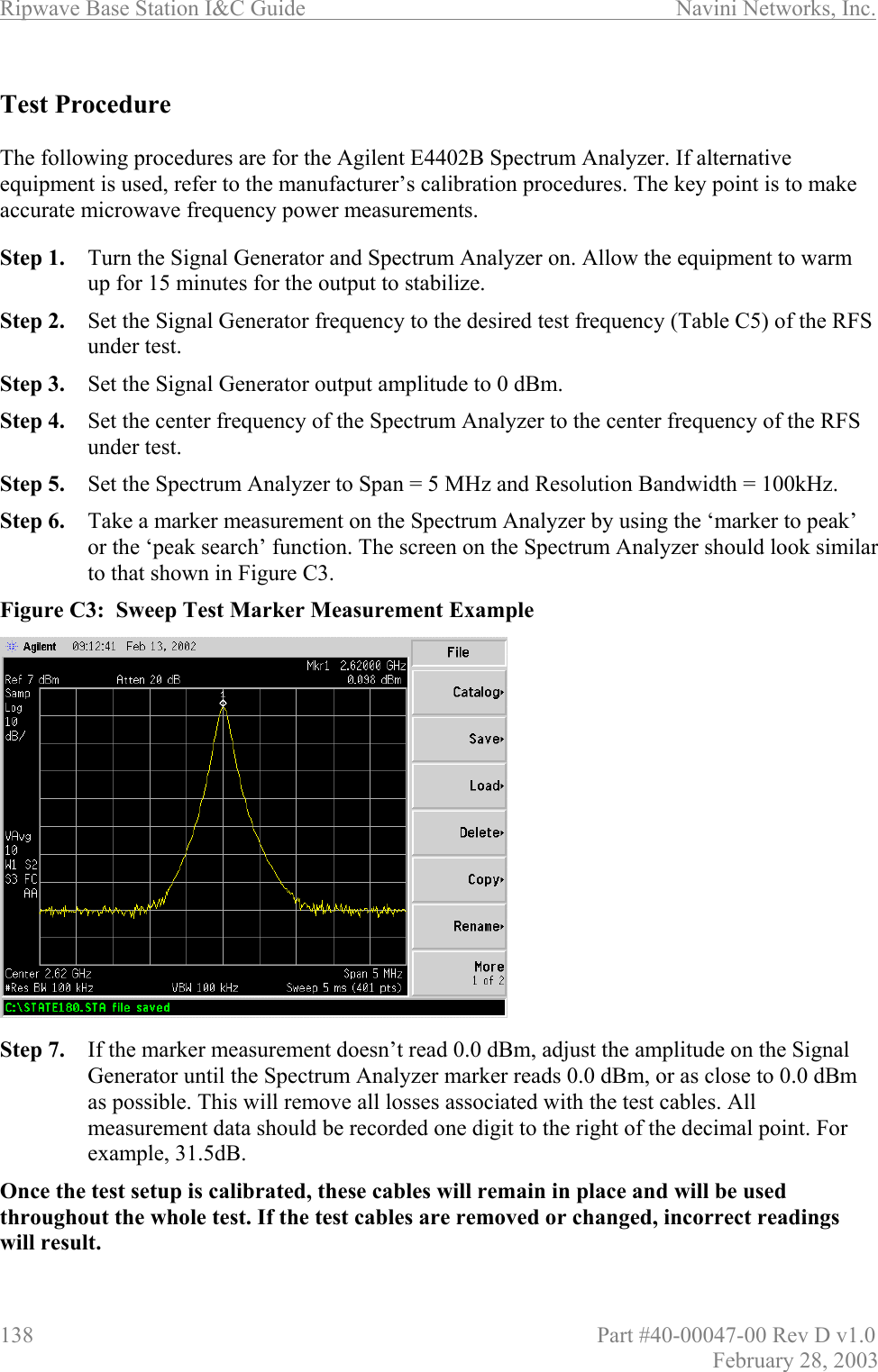
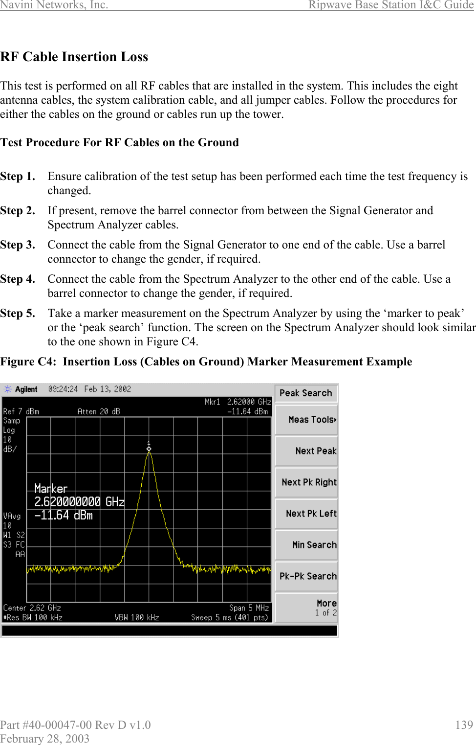
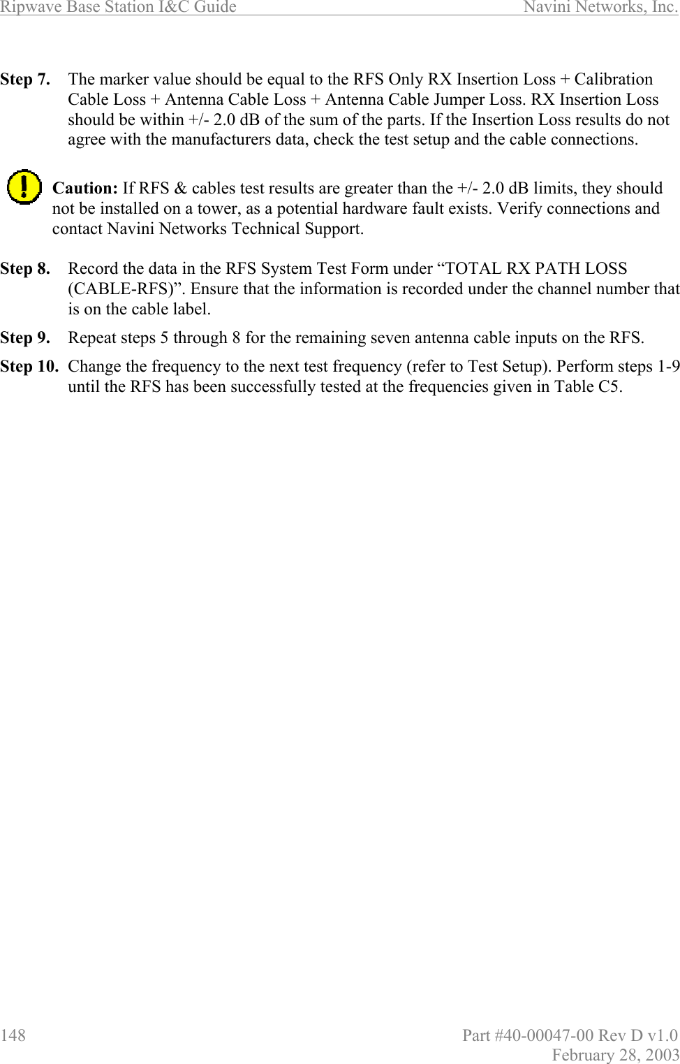
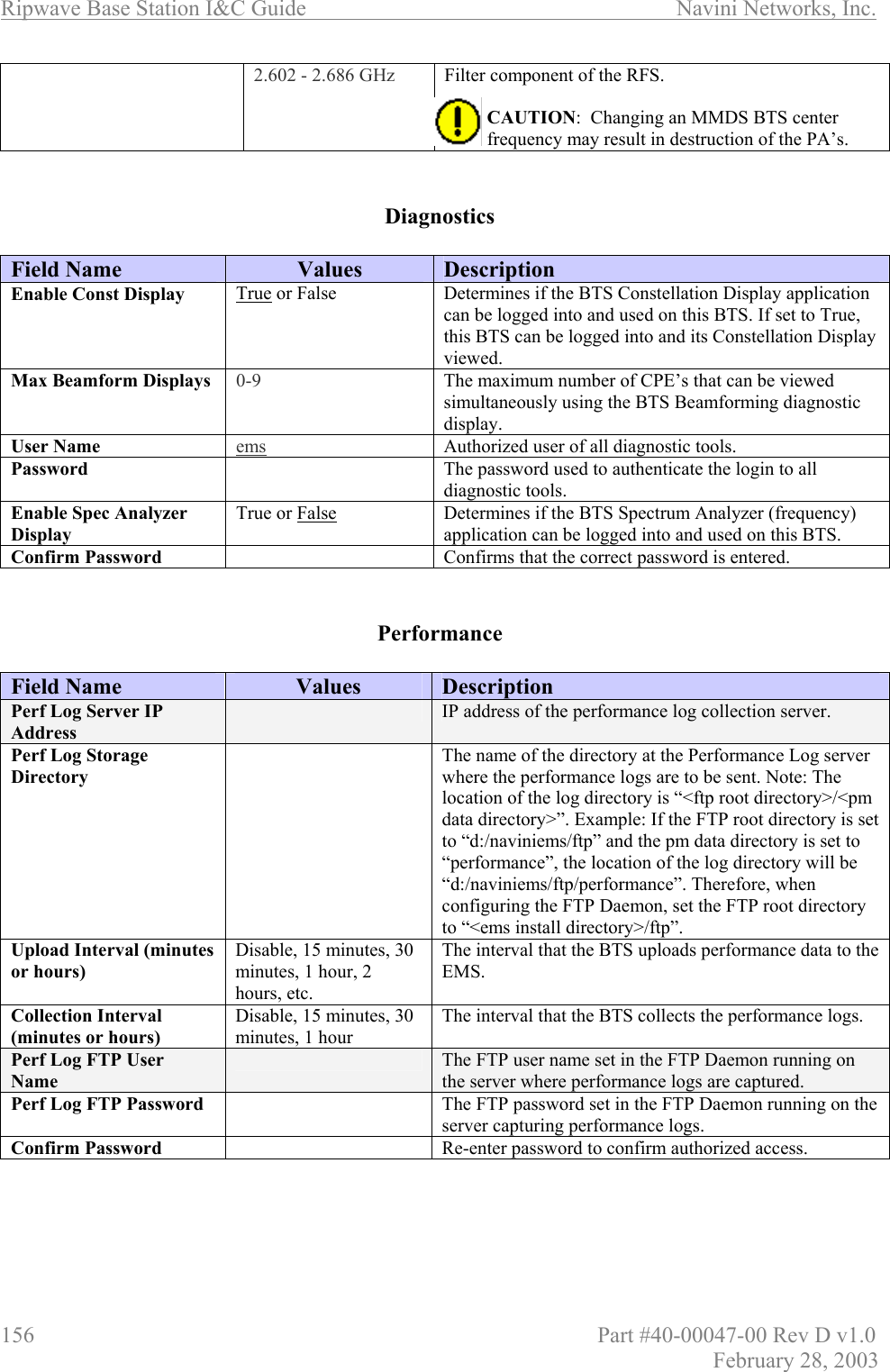
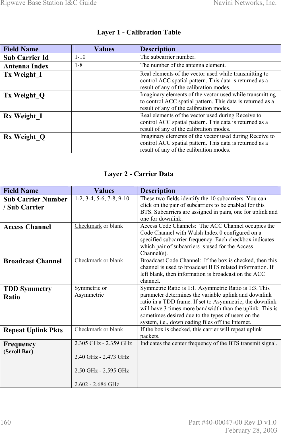
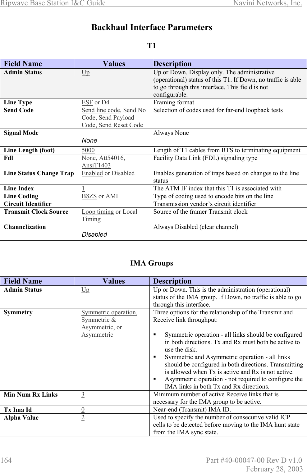
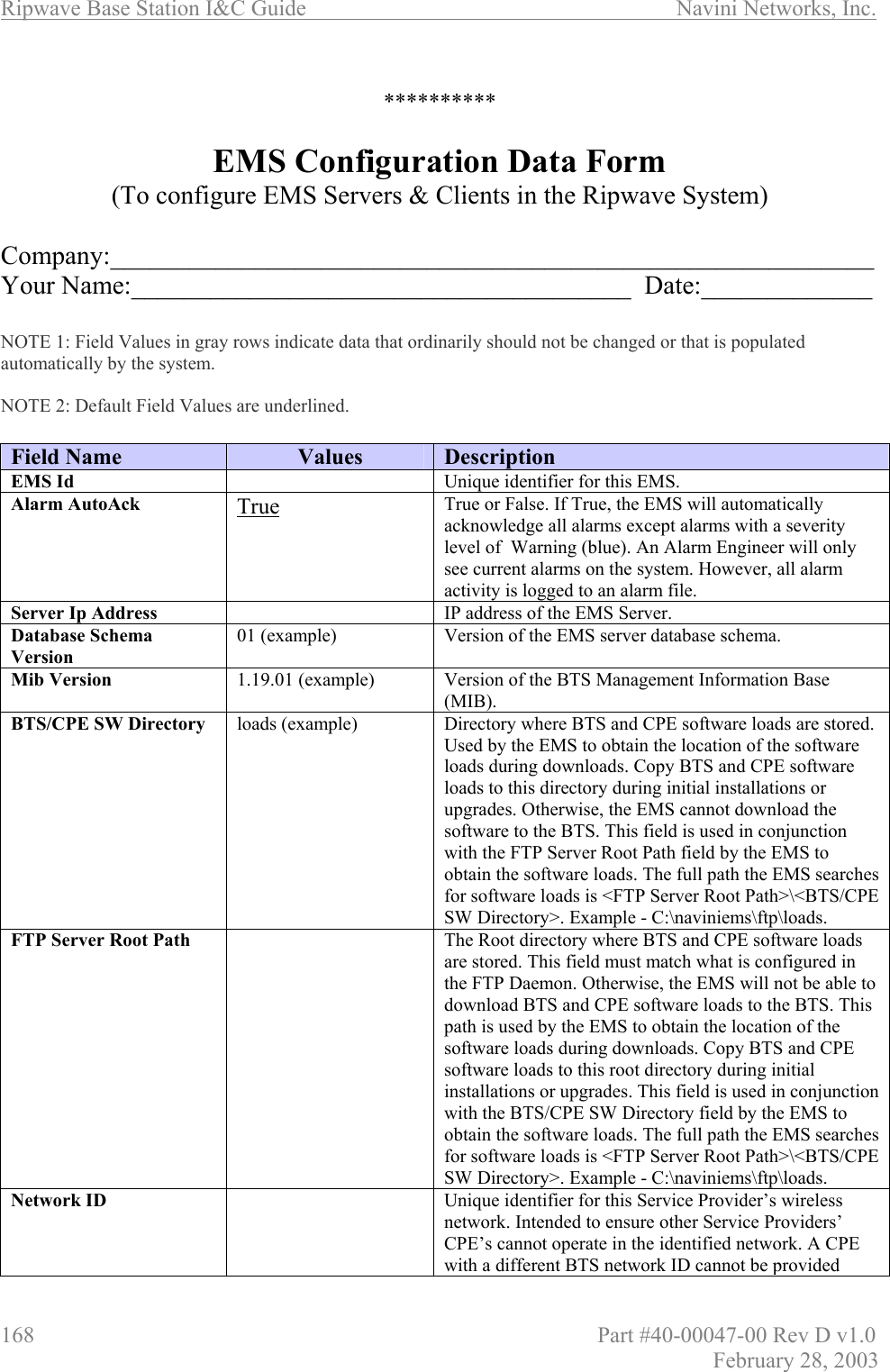
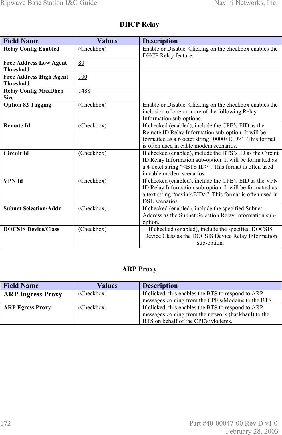
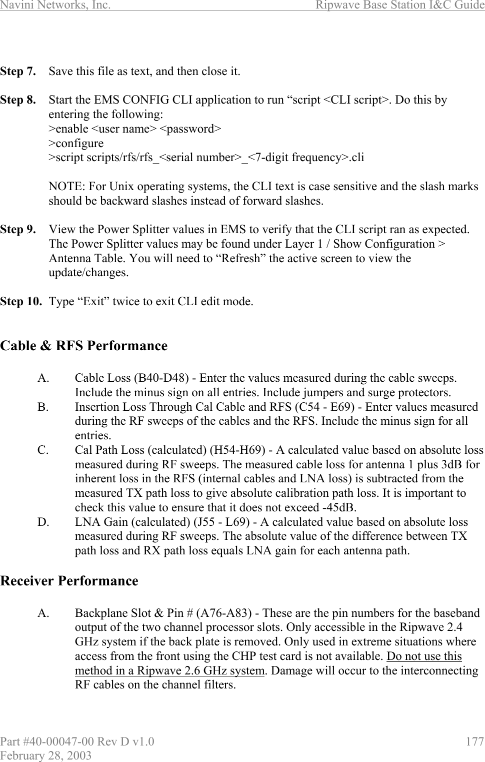
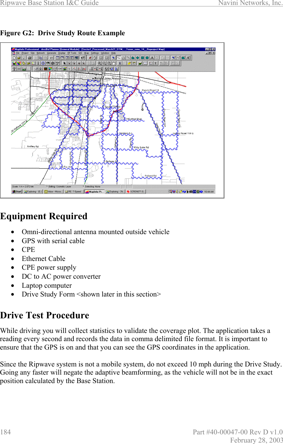
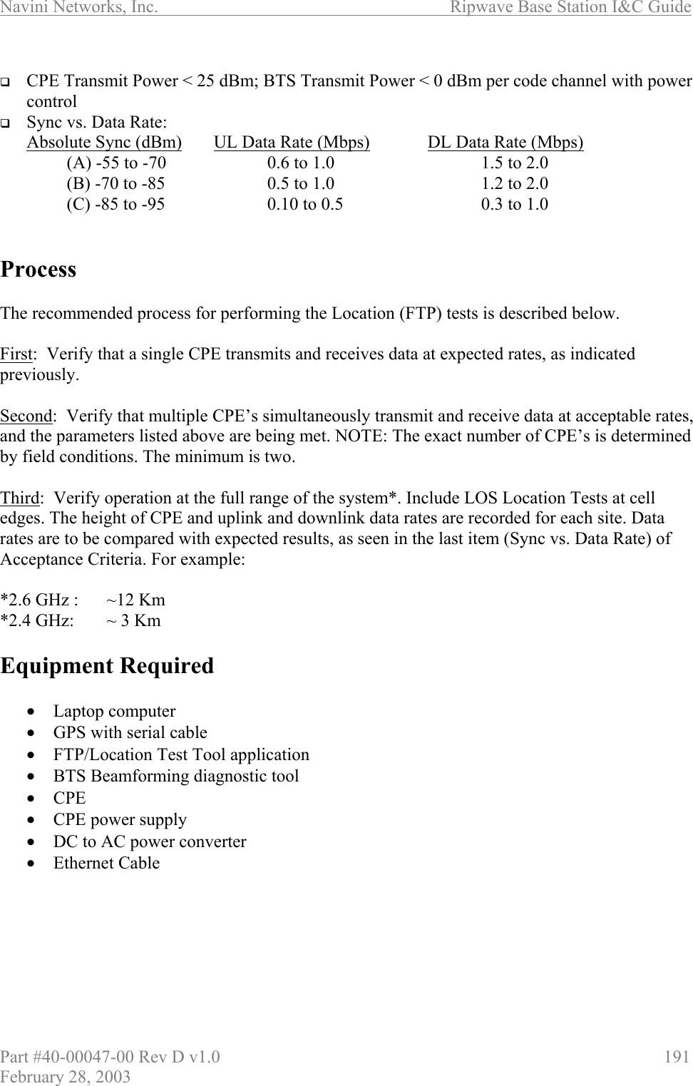
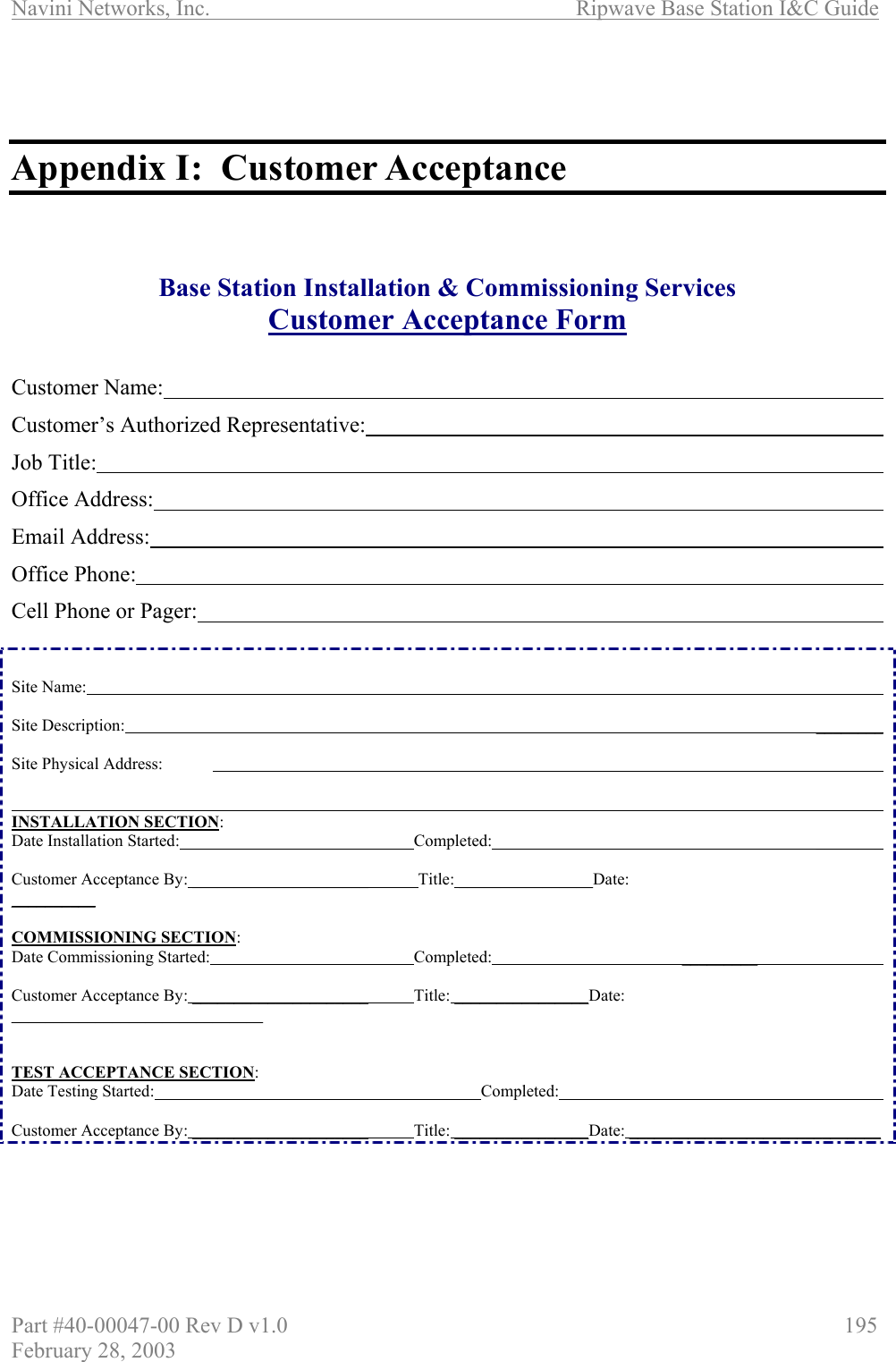
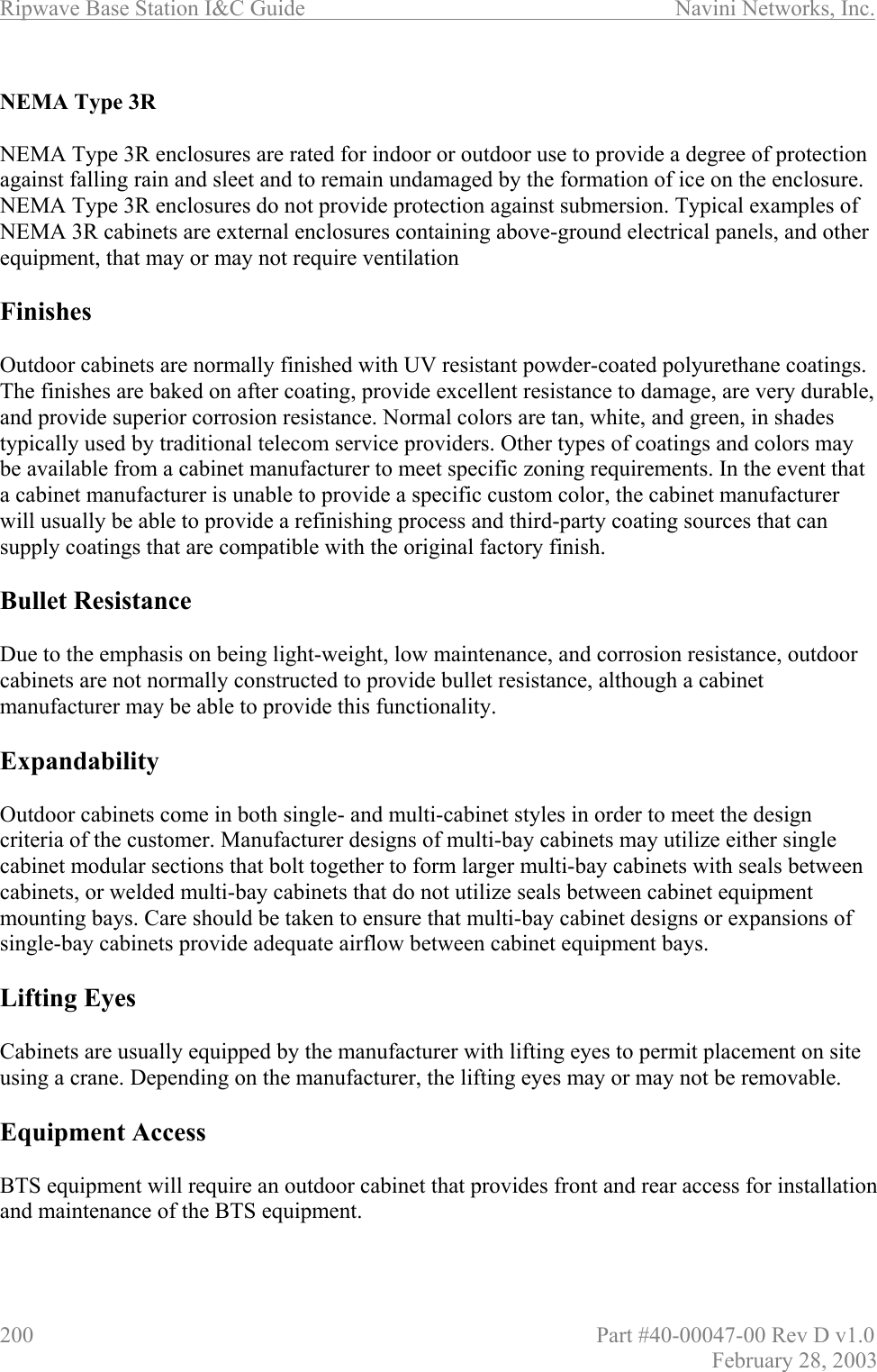
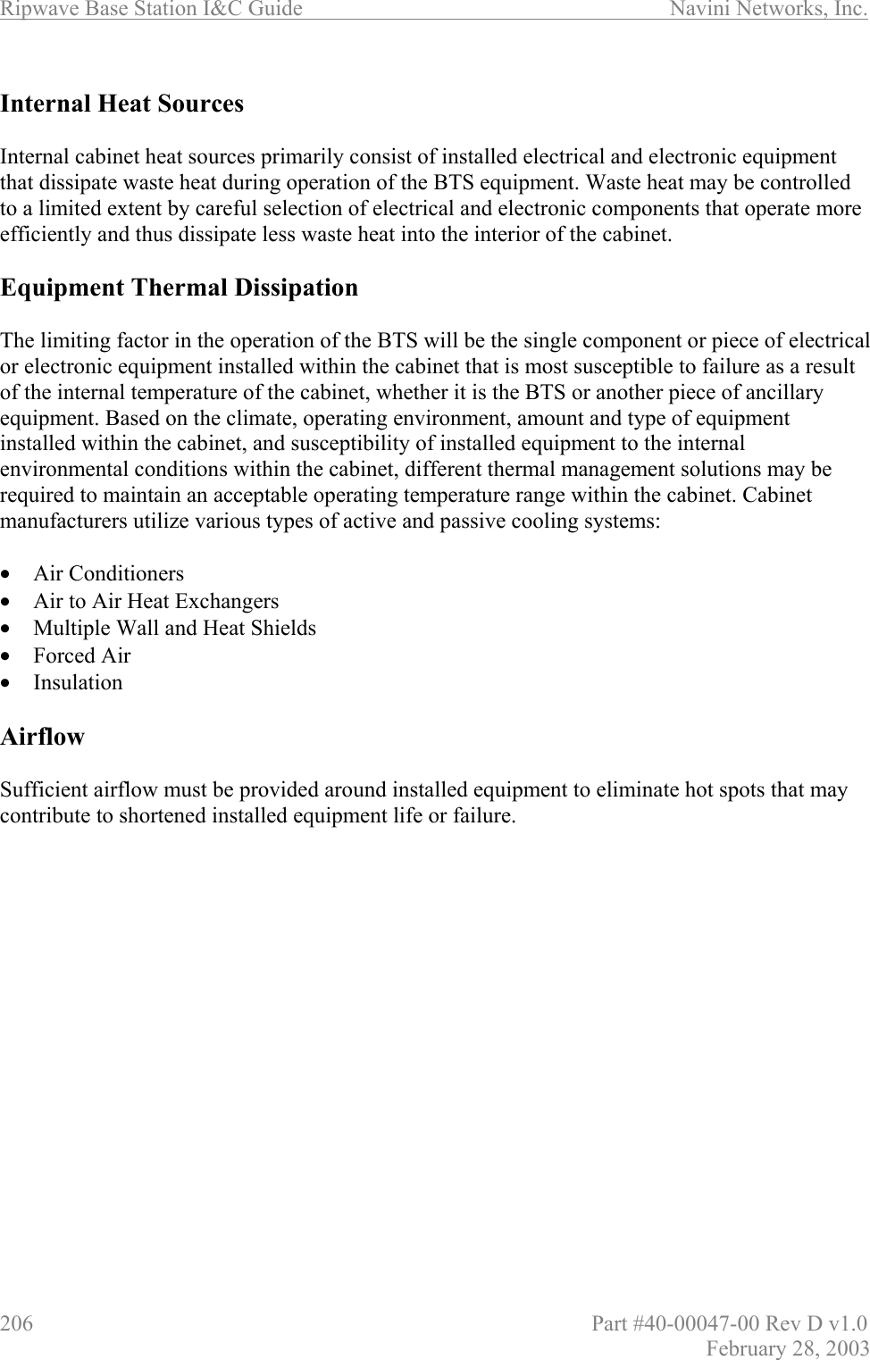
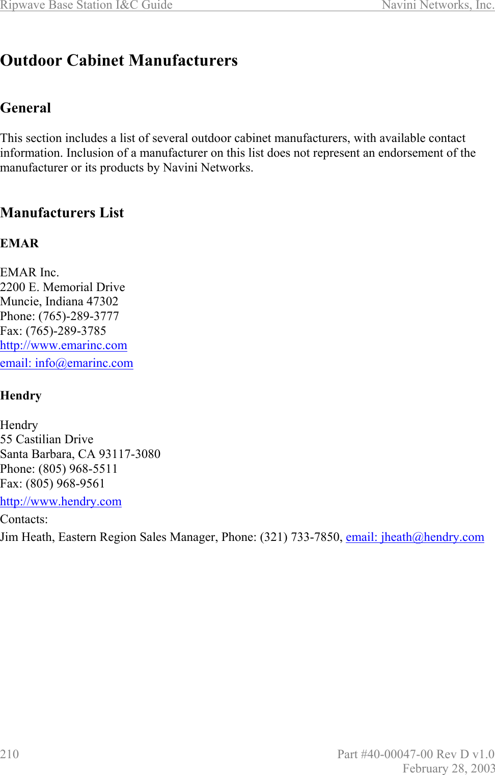
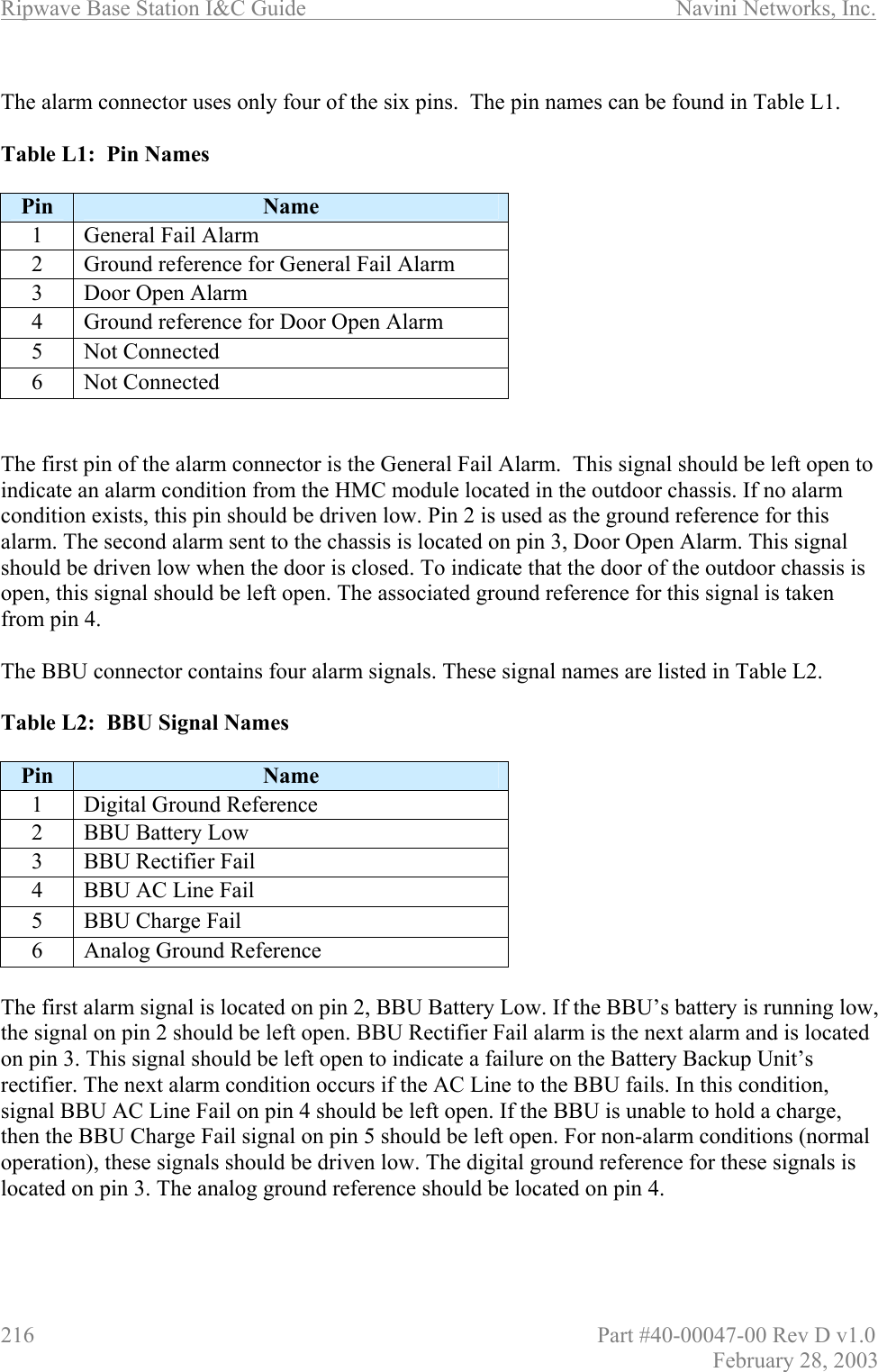
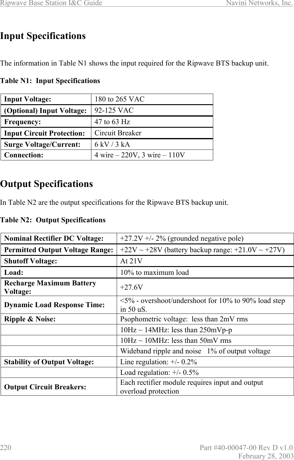
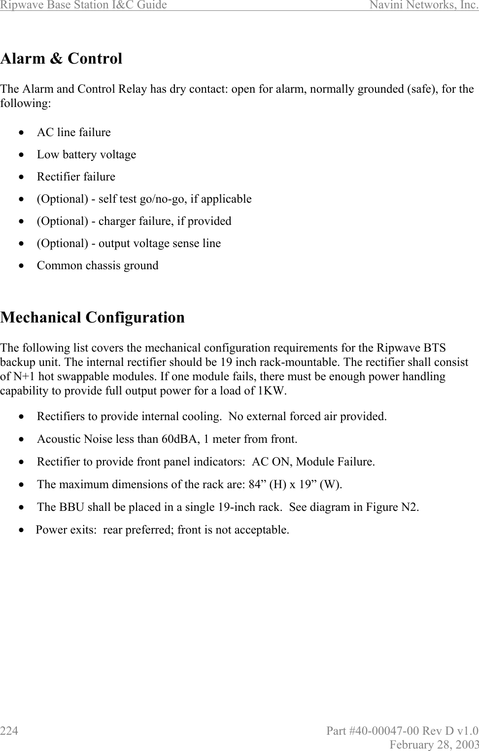
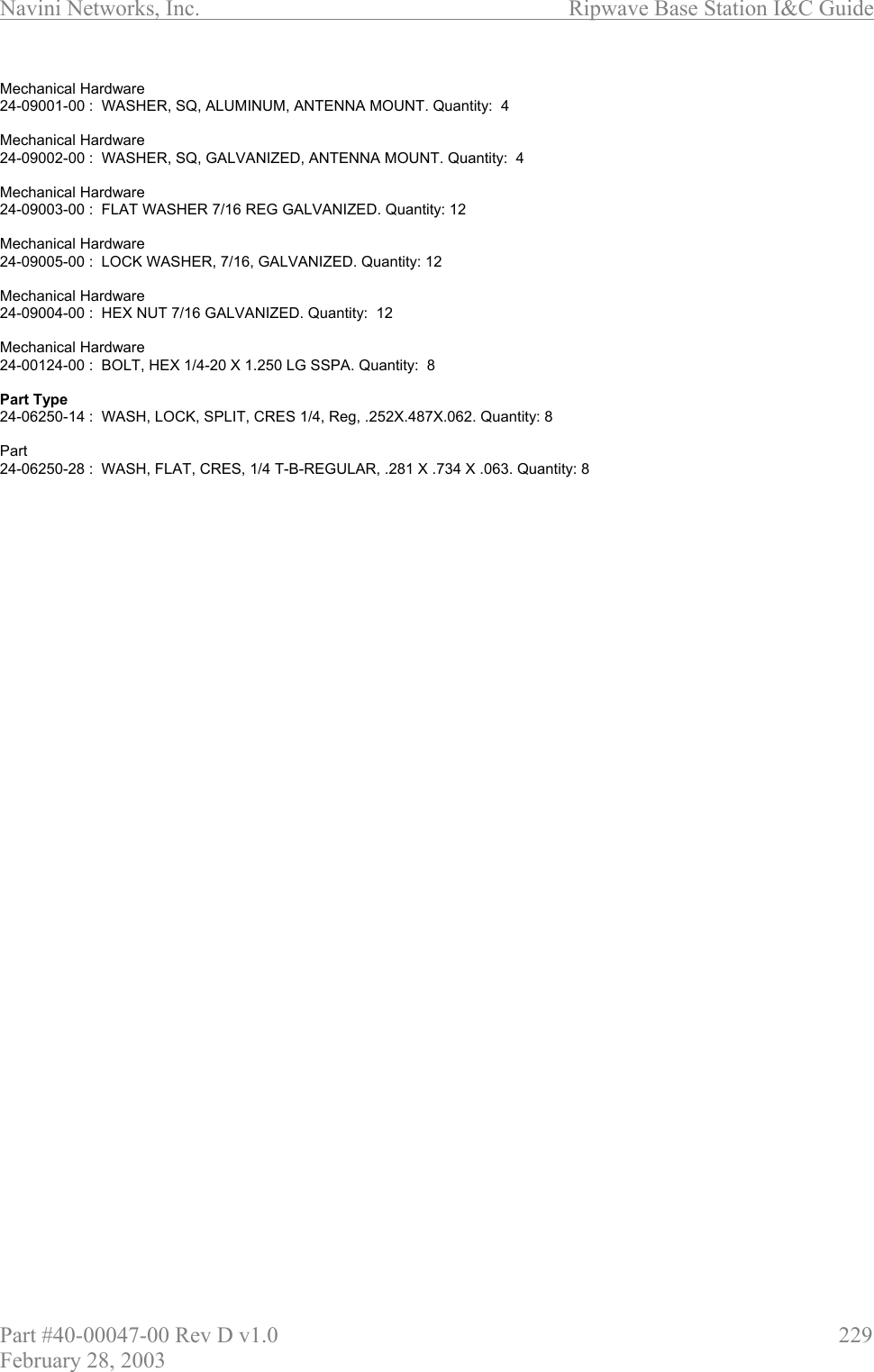
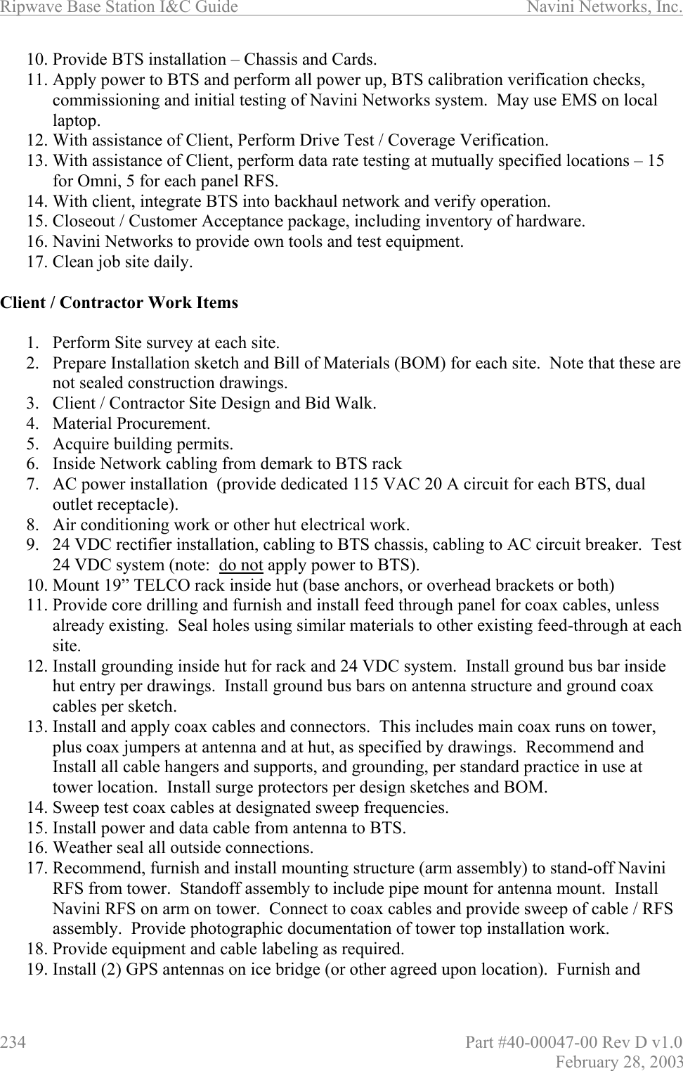
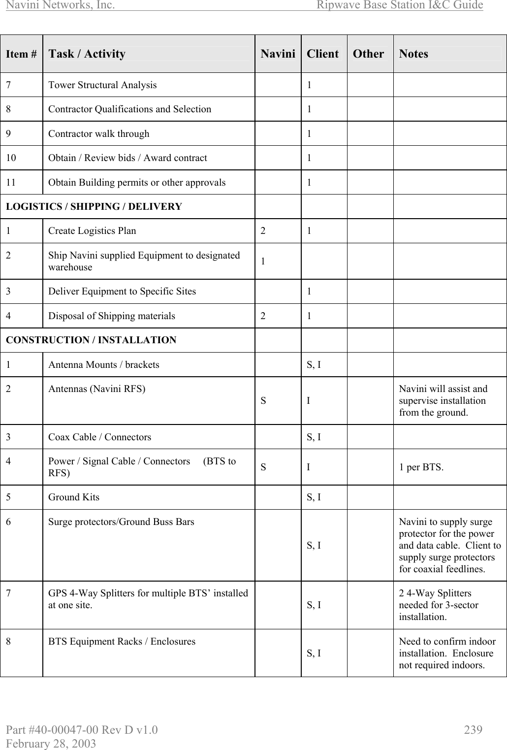
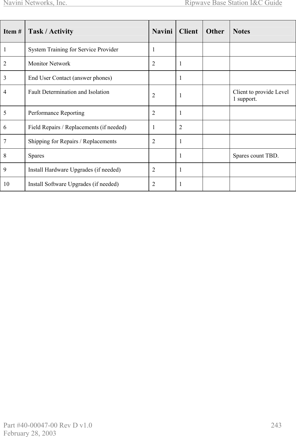
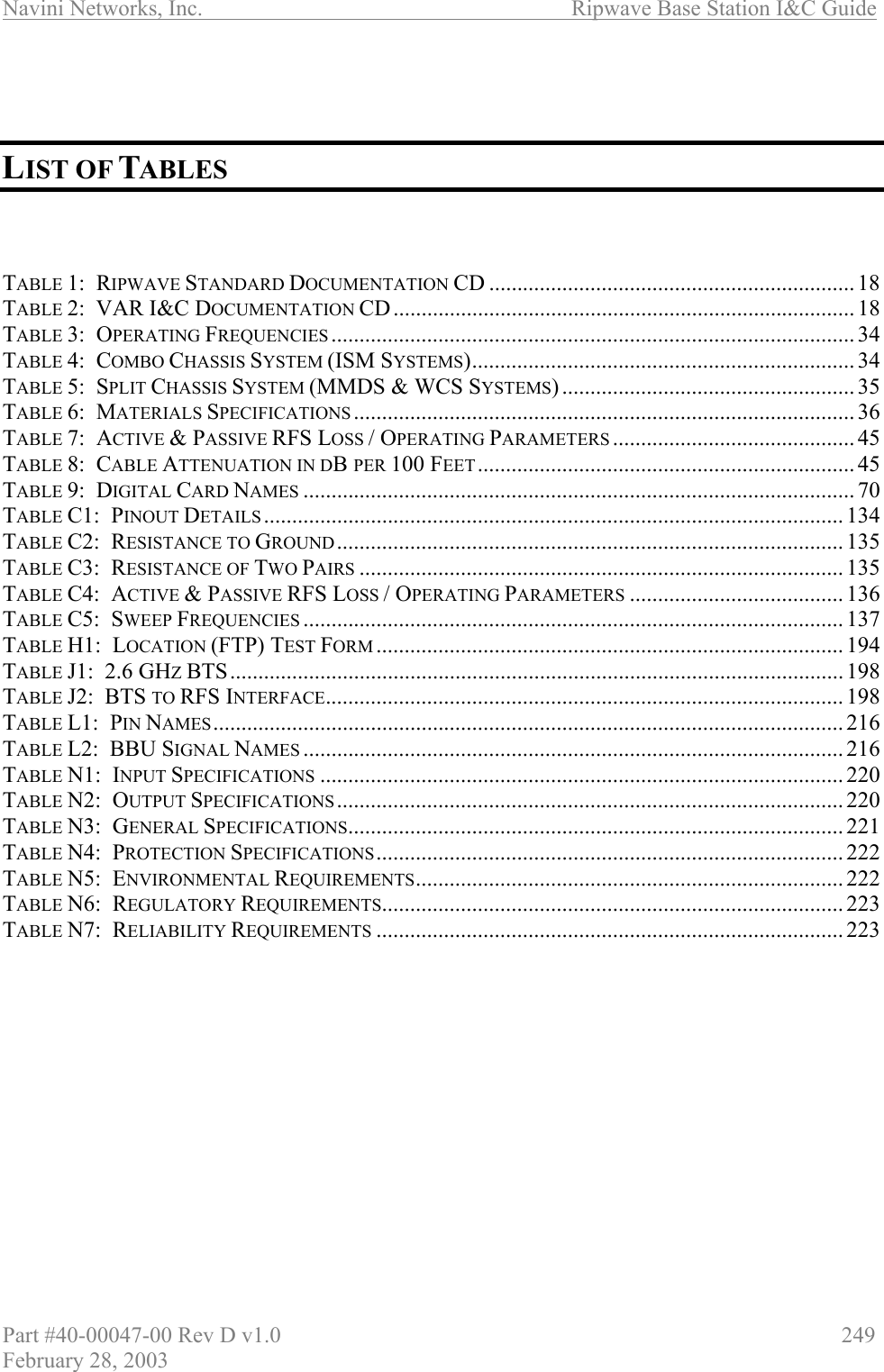
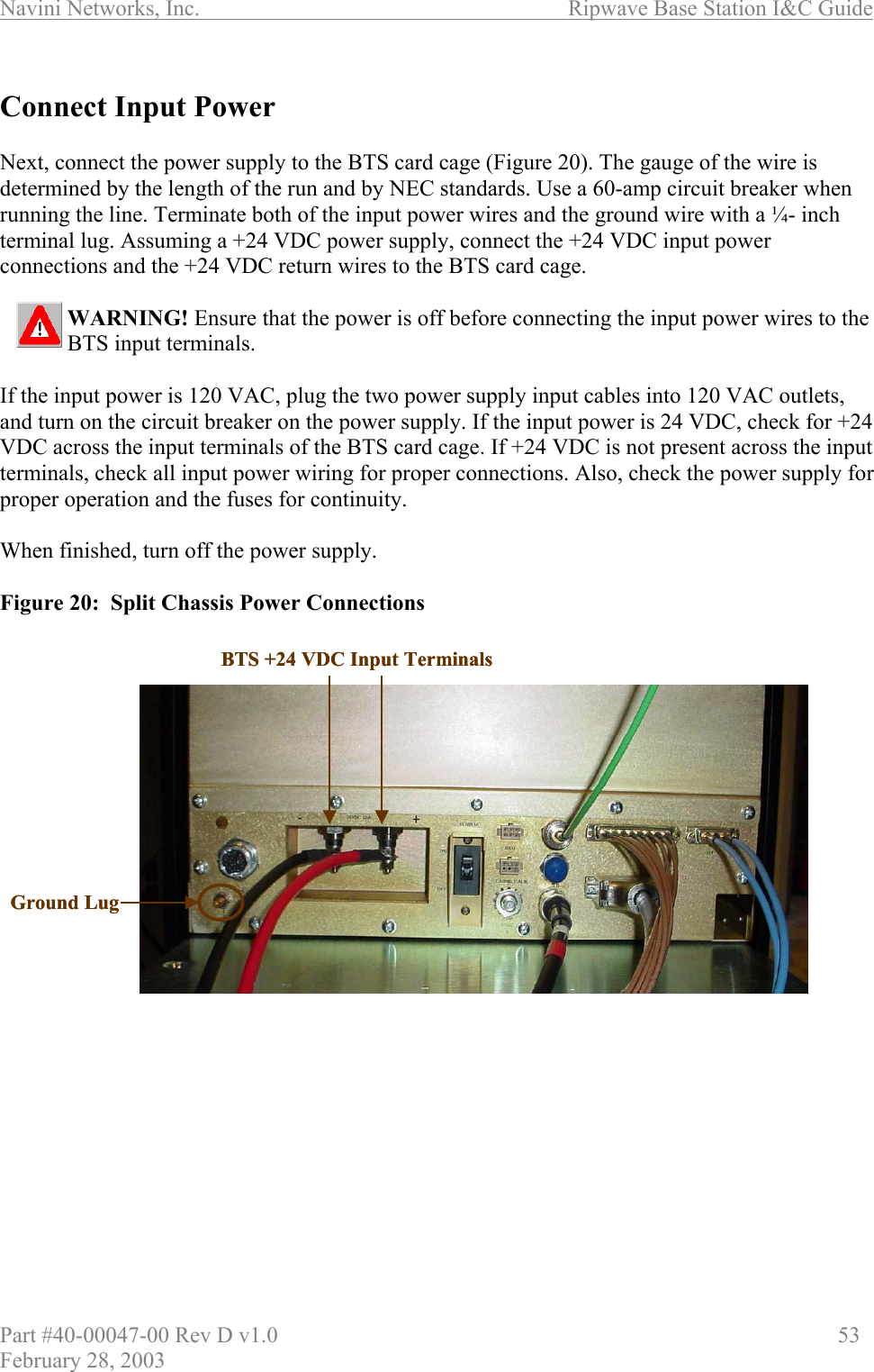
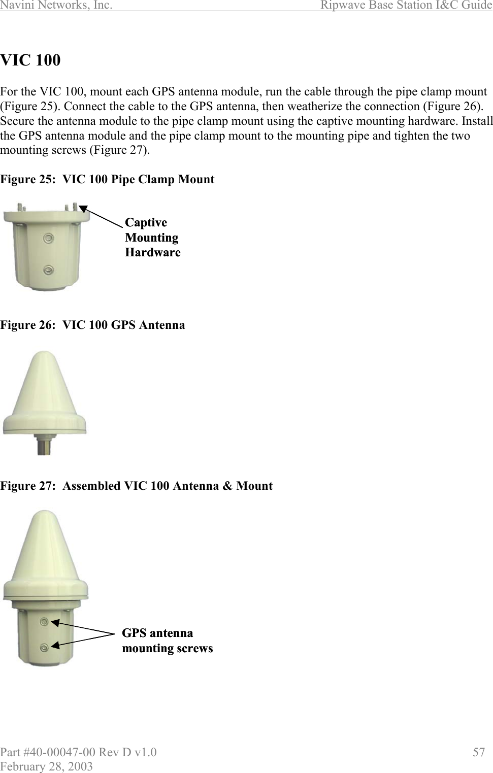
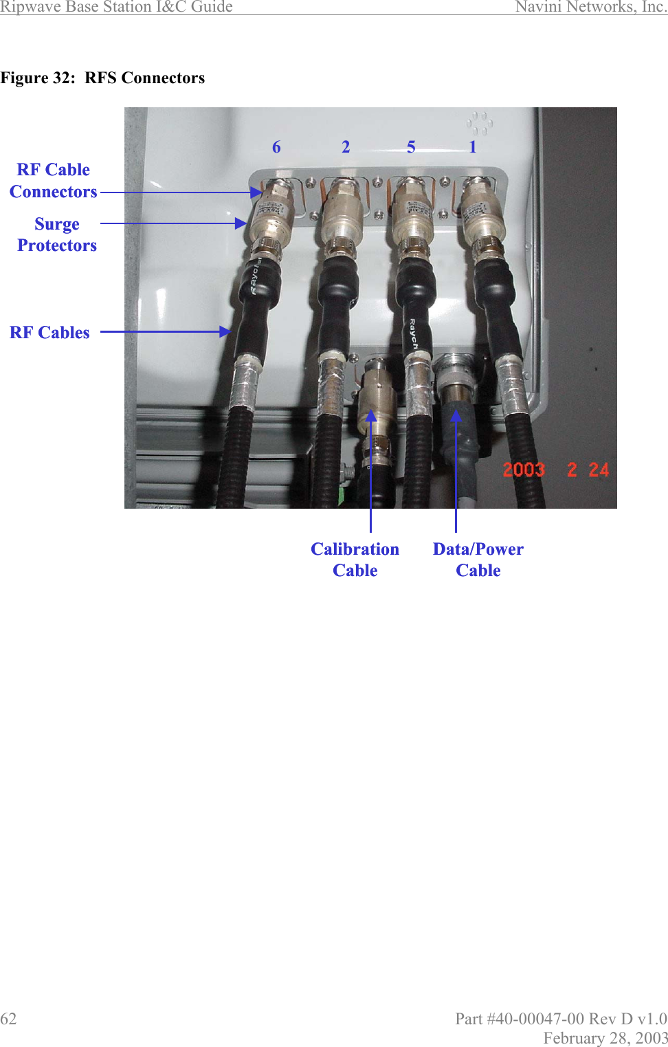
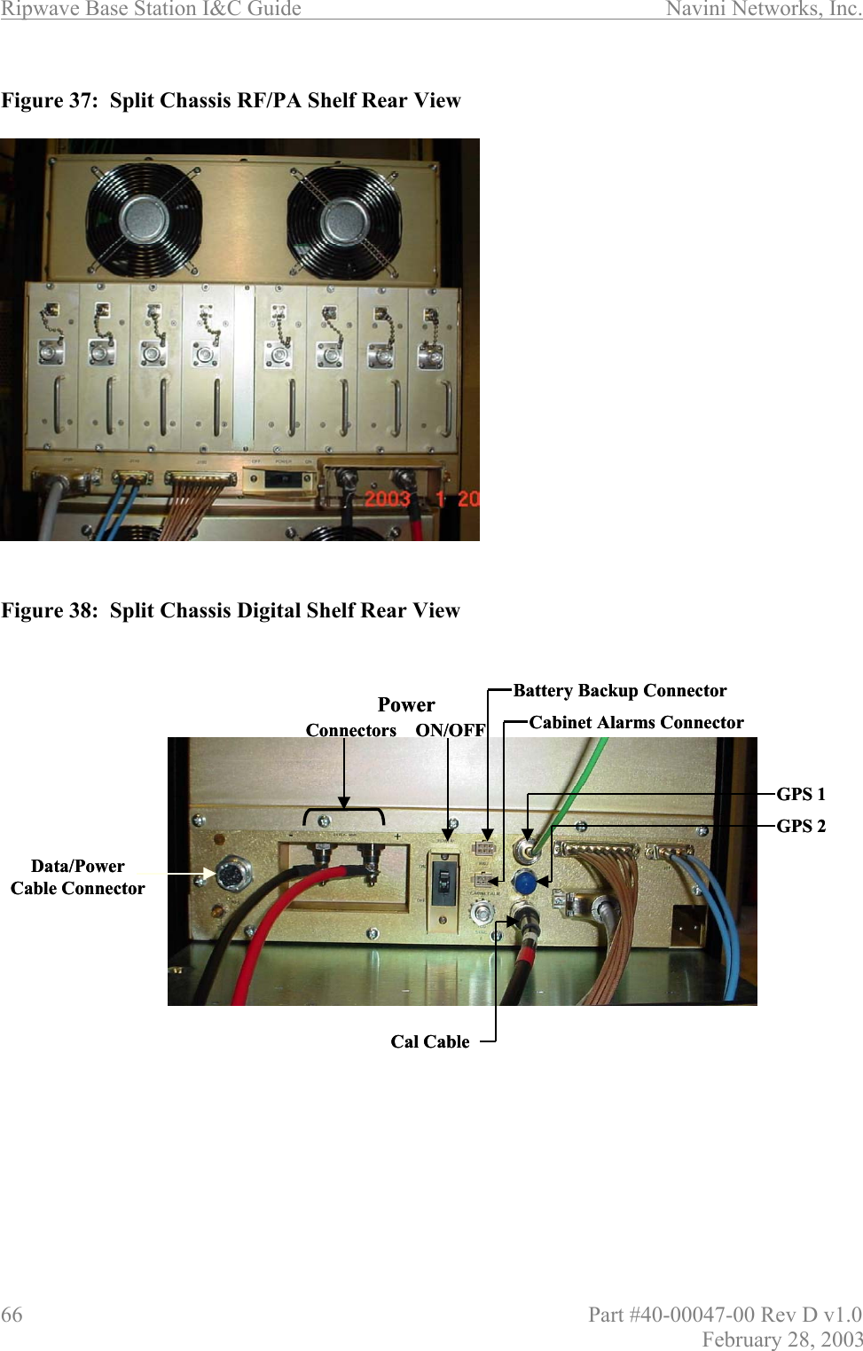
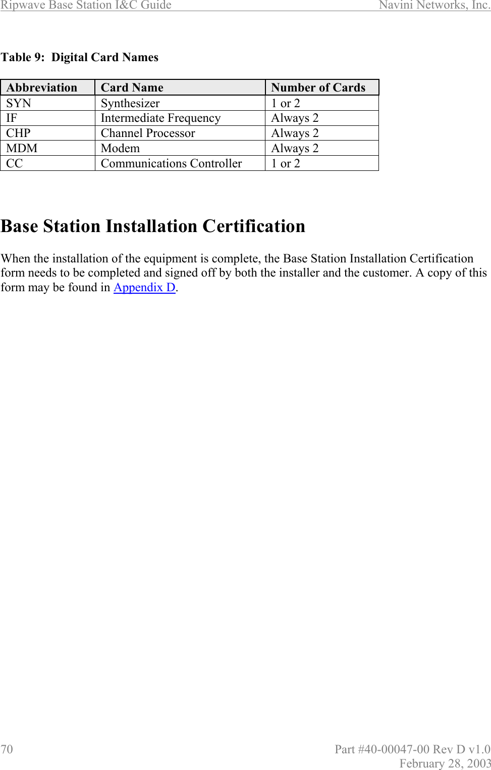
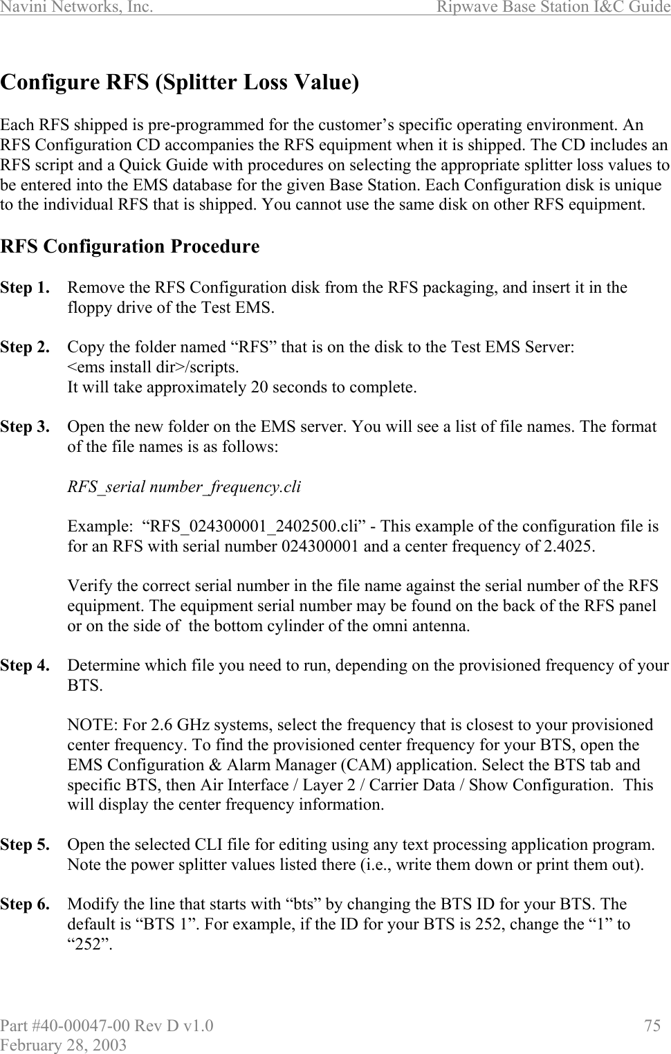
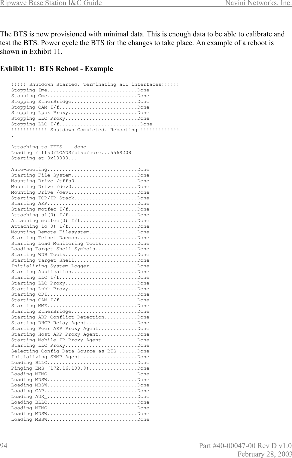
![Ripwave Base Station I&C Guide Navini Networks, Inc. 136 Part #40-00047-00 Rev D v1.0 February 28, 2003 Table C4: Active & Passive RFS Loss / Operating Parameters PA Max Output Power [dBm] BTS Max Output power with *Filter [dBm] CAL Cable Min Loss CAL Cable Max Loss RF Cable Min Loss [dB] Active RFS Loss Typ [dB] Passive RFS Loss Typ [dB] TX Pwr to Ant Min [dBm] TX Pwr to Ant Max [dBm] RX Power to Ant Min [dBm] RX Power to Ant Max [dBm] Notes 2.3 +38 +37 3.0 6.0 0 3.2 1.7 20 35 -95 -75 2.4 +37 N/A 4.0 9.5 0 3.2 1.7 10 25 -85 -65 -05 SYN 2.4 +37 N/A 3.0 4.5 0 3.2 1.7 18 30 -95 -70 -01 SYN 2.5 +39 +38 3.0 6.0 0 3.2 1.7 20 35 -95 -75 2.6 EFGH +39 +38 3.0 6.0 0 3.2 1.7 20 35 -95 -75 2.6 EF +37 +35 3.0 4.5 0 3.2 1.7 20 35 -95 -75 -05 SYN * Channel filter for 2.5/2.6 or Block Filter for 2.3 has 1.0 +/- 0.2 dB Insertion Loss * Channel filter for 2.6 EF Combo is 1.8 +/- 0.2 dB including cable to backplane. Equipment Required • Signal Generator - Agilent 8648C, or suitable alternative, tunable to the RFS center frequency • Spectrum Analyzer - Agilent E4402B, or equivalent • Signal Generator cable and Spectrum Analyzer cable – Gender can be changed using a barrel connector • Male and Female barrel connectors for Signal Generator cable and Spectrum Analyzer cable connections • Power/data test cable • Navini RFS Test Box Equipment Settings Spectrum Analyzer: • Spectrum Analyzer - 5M • RBW - 100 KHz • VBW - 100 KHz • Sweep Time - Auto • Frequency (Provided in Table C5) Signal Generator: • Amplitude - 0 dB • Frequency (Provided in Table C5)](https://usermanual.wiki/Cisco-Systems/ISM-BTS-R1.Users-Manual-Section2/User-Guide-387217-Page-87.png)