Cisco Systems MWIBS1900 PCS Base Station User Manual HW fcc op23
Cisco Systems Inc PCS Base Station HW fcc op23
UserManual.wiki
>
Cisco Systems
>
MWIBS1900 User Manual
Operational manual
Navigation menu
Upload a User Manual
Namespaces
Wiki Guide
HTML
PDF
Info
Views
User Manual
Discussion / Help
Navigation
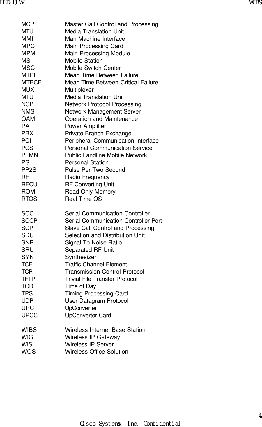
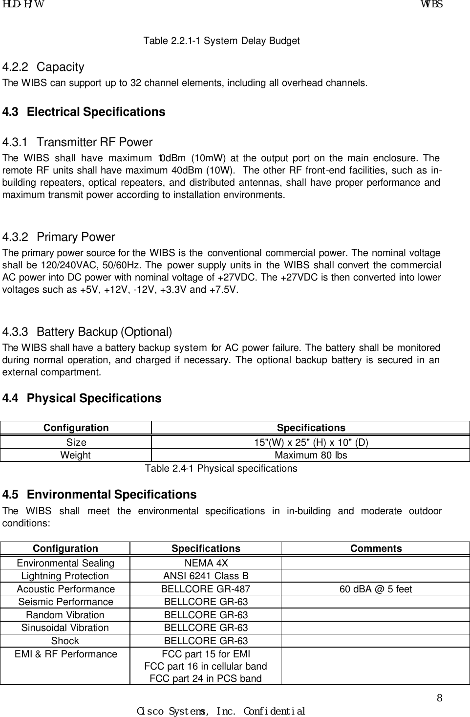
![HLD-H/W WIBS 11 Cisco Systems, Inc. Confidential 7. System Starts Up Before ScMenu program activates, the environment which enables the program work properly should be installed. PC connects to BTS system through RS 232 port and initialize IP network to get download test program from our own server. Then, the test program, ScMenu , can be started for call processing related test. Using dummy terminal, we may starts up this process, and typing in shift-C use for restarting up. VxWorks System Boot Copyright 1984-1998 Wind River Systems, Inc CPU: ExiO WiBS BMPC Version: 5.4 BSP version: 2.0/1 Creation date: Nov 26 2000, 17:40: Press any key to stop auto-boot... 1 0 auto-booting... boot device : motfcc unit number : 0 processor number : 0 host name : WIS file name : vxWorks inet on ethernet (e) : 209.237.49.226:ffffffc0 host inet (h) : 209.237.49.228 gateway inet (g) : 209.237.49.193 user (u) : wibs ftp password (pw) : wibs flags (f) : 0x8 target name (tn) : wibs17 Attached TCP/IP interface to motfcc0. Attaching network interface lo0... done. Loading... 2866180 Starting at 0x100000... [motFccInitMem] memArea 0x201c0000, memSize 0x27eef Attached TCP/IP interface to motfcc unit 0 Attaching interface lo0...done Adding 5683 symbols for standalone.](https://usermanual.wiki/Cisco-Systems/MWIBS1900/User-Guide-152813-Page-11.png)
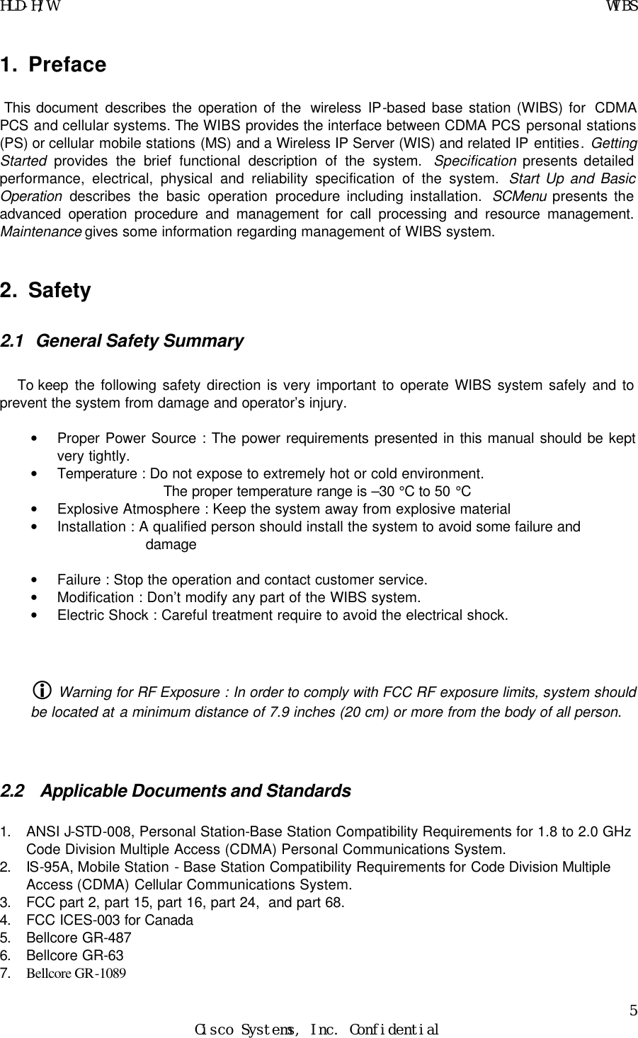
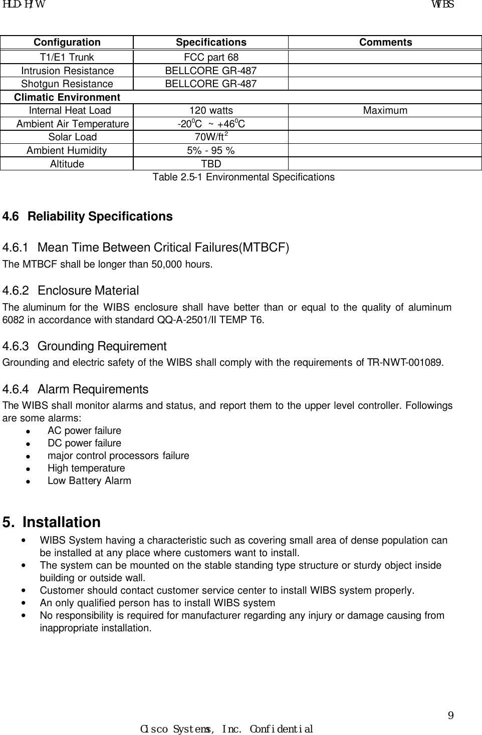
![HLD-H/W WIBS 12 Cisco Systems, Inc. Confidential ]]]]]]]]]]]]]]]]]]]]]]]]]]]]]]]]]]]]]]]] ]]]]]]]]]]]]]]]]]]]]]]]]]]]]]]]]]]]]]]] ]]]]]]]]]]]]]]]]]]]]]]]]]]]]]]]]]]]]]] ]]]]]]]]]]] ]]]] ]]]]]]]]]] ]] ]]]] (R) ] ]]]]]]]]] ]]]]]] ]]]]]]]] ]] ]]]] ]] ]]]]]]] ]]]]]]]] ]]]]]] ] ]] ]]]] ]]] ]]]]] ] ]]] ] ]]]] ]]] ]]]]]]]]] ]]]] ]] ]]]] ]] ]]]]] ]]]] ]]] ]] ] ]]] ]] ]]]]] ]]]]]] ]] ]]]]]]] ]]]] ]] ]]]] ]]]]] ] ]]]] ]]]]] ]]]]]]]] ]]]] ]] ]]]] ]]]]]]] ]]]] ]]]]]] ]]]]] ]]]]]] ] ]]]]] ]]]] ]] ]]]] ]]]]]]]] ]]]] ]]]]]]] ]]]]] ] ]]]]]] ] ]]] ]]]] ]] ]]]] ]]]] ]]]] ]]]] ]]]]]]]] ]]]]] ]]] ]]]]]]] ] ]]]]]]] ]]]] ]]]] ]]]] ]]]]] ]]]]]]]]]]]]]]]]]]]]]]]]]]]]]] ]]]]]]]]]]]]]]]]]]]]]]]]]]]]] Development System ]]]]]]]]]]]]]]]]]]]]]]]]]]]] ]]]]]]]]]]]]]]]]]]]]]]]]]]] VxWorks version 5.4 ]]]]]]]]]]]]]]]]]]]]]]]]]] KERNEL: WIND version 2.5 ]]]]]]]]]]]]]]]]]]]]]]]]] Copyright Wind River Systems, Inc., 1984-1999 CPU: ExiO WiBS BMPC. Processor #0. Memory Size: 0x2000000. BSP version 2.0/1. WDB: Ready. task spawned: id = 0x1c40560, name = t1 [LdPld] SNMP_TRAP_PKT send to request WiBS Number. -> [LdPld] Waiting for SNMP_SET_PKT with WiBS Number from OAM. [Mibway] Launching the Rapid Logic WEB Server! [Mibway] motfcc0 IP Address : 209.237.49.226 [LdPld] OK! Got the SNMP_SET_PKT with WiBS Number from OAM. [LdPld] WiBS Number is "17"](https://usermanual.wiki/Cisco-Systems/MWIBS1900/User-Guide-152813-Page-12.png)
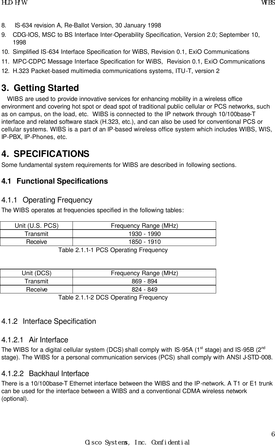
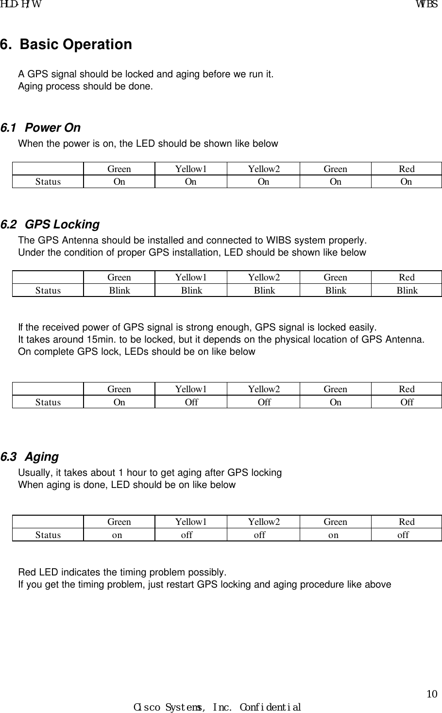
![HLD-H/W WIBS 13 Cisco Systems, Inc. Confidential [LdPld] PLD loading start. [LdPld] Loading PLD (common.o, pld17.o) [LdPld] Loading common.o [LdPld] Loading common.o...... OK !! [LdPld] Loading pld17.o [LdPld] Loading pld17.o .......OK !! [LdPld] Loading snmp.out Wait for PLD download... [LdPld] Loading snmp.out.... OK !! [LdPld] Loading initPgm.out [LdPld] Loading initPgm.out....OK !! [LdPld] Looking up initPgm in symbol table ... [LdPld] Spawning initPgm ... [InitPgm] PLD SNMP Tree Add. task spawned: id = 0x1c28f48, name = t2 [LdPld] [LdPld] ********** ALL PLD Loading OK. ************ [InitPgm] Link PLD Instance Start. [InitPgm] Applicaiton Program Start. PLD downloaded -> simStart “IP Addr1”,”IP Addr2”, (ex: "209.237.49.226","209.237.49.228") =>This command need to be typed in [AlInit] MyIp 0xd1ed31e2(209.237.49.226), McpIp 0xd1ed31e2(209.237.49.226), NcpIp 0xd1ed31e4(209.237.49.228), CaIp 0xd1ed31e4(209.237.49.228) [ddInit] ddBspAdjust() ok! [ddInit] DdBufPoolInit() ok! [ddInit] DdPortsInit(DdPORTS_NUM_1) ok! [ddInit] DdTickInit(0) ok! [ddInit] DdBrgInit(0) ok! [ddInit] DdTimerInit(DdTIMER_NUM_4) ok! [ddInit] DdSccInit(0) ok! [ddInit] DdCPrxInit(0) ok! [ddInit] DdSmcInit(0) ok! [ddInit] DdTodInit(0) ok! [ddInit] DdIrqInit(0) ok! [ddInit] Dd1PpsInit(0) ok! [ddInit] DdCacheInit() ok! [CLS] CLS initialized [DBX] Initialized [GPSRX] GPSRX initialized [SCP] scInitScp() initilization started [RFCX] TxAtt: 63.0dB [RFCX] rfSetDownSynth Down Synth(65.05MHz) Locked](https://usermanual.wiki/Cisco-Systems/MWIBS1900/User-Guide-152813-Page-13.png)
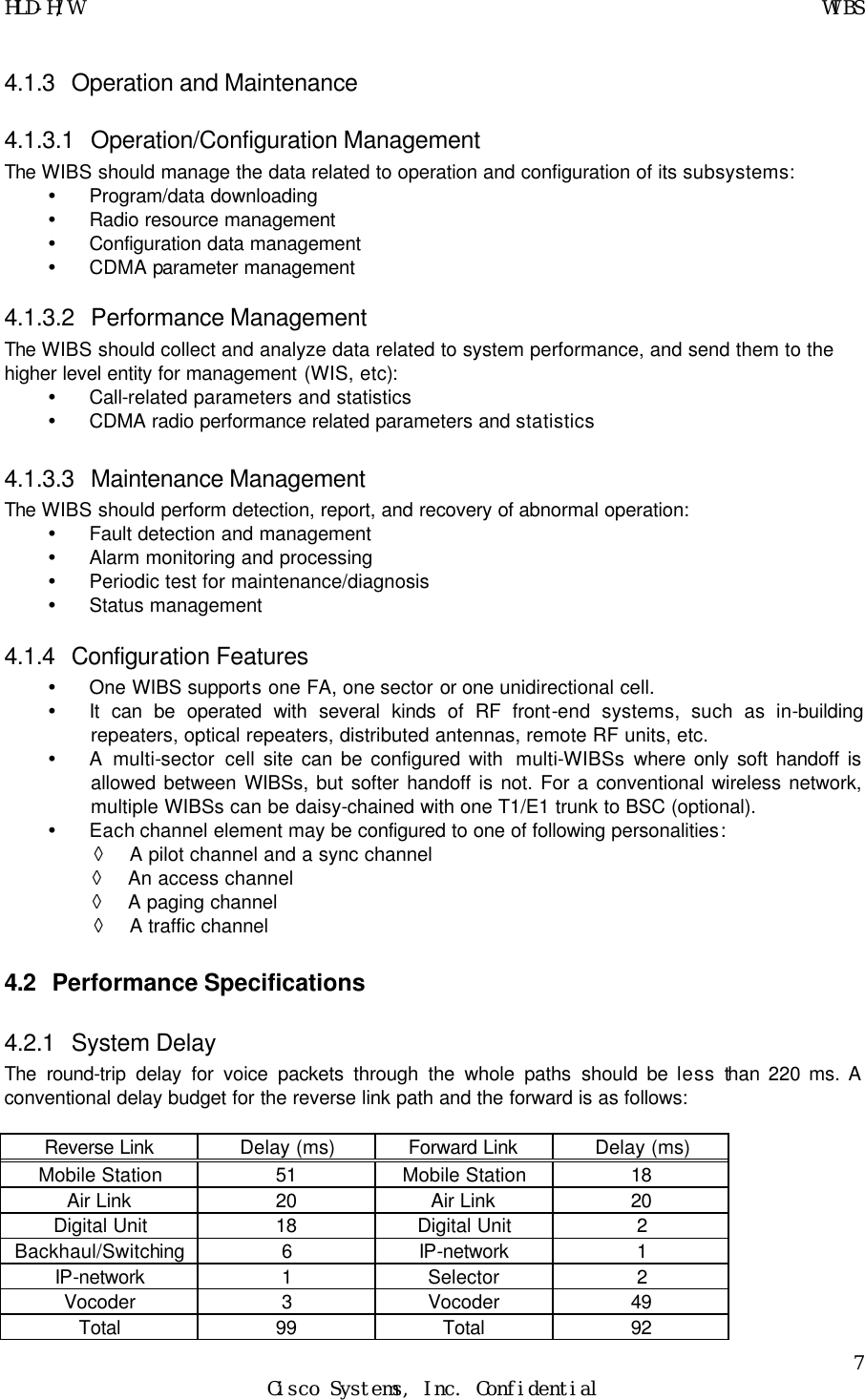
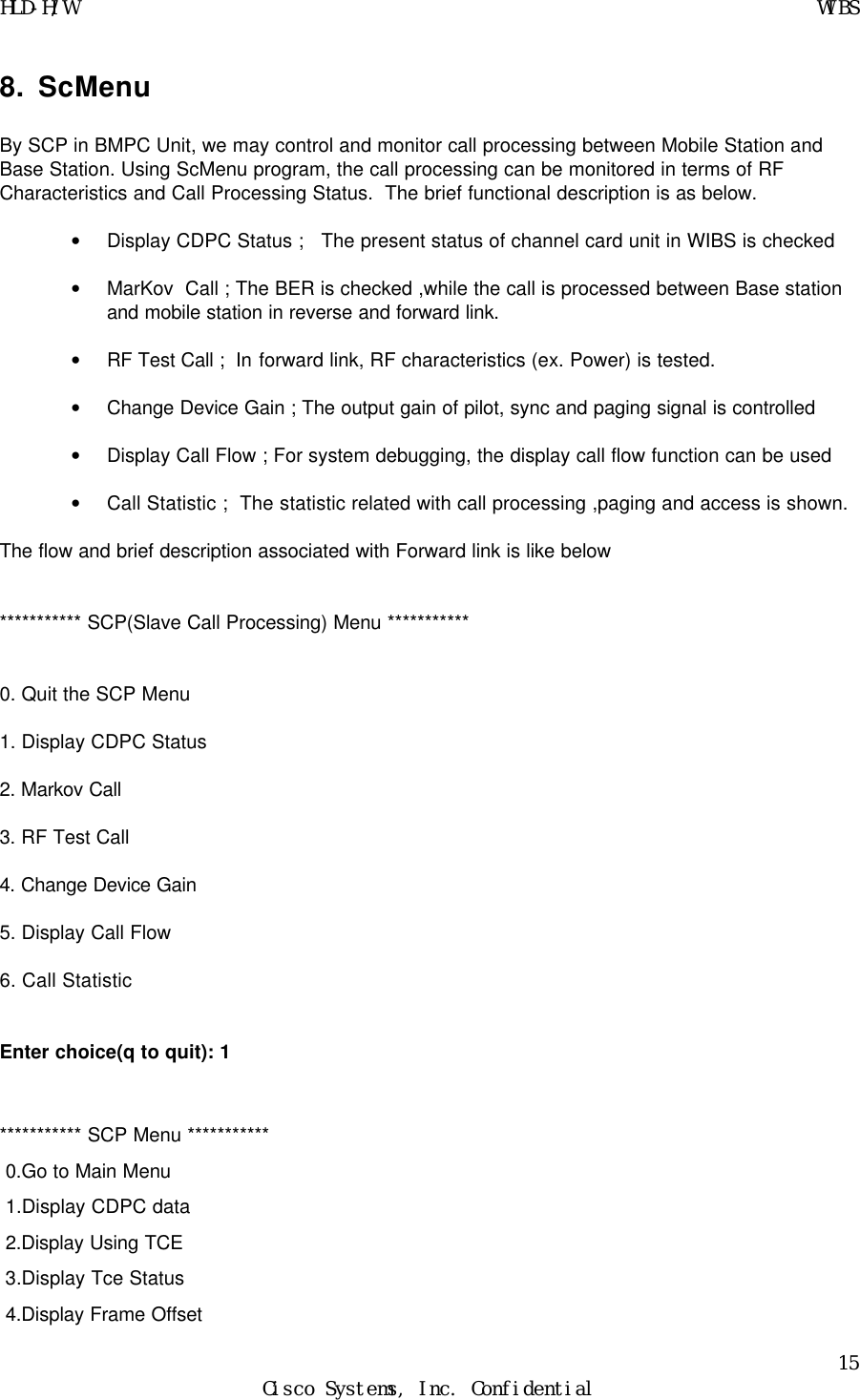
![HLD-H/W WIBS 14 Cisco Systems, Inc. Confidential [RFCX] rfSetUpSynth Up Synth(145.05MHz) Locked [RFCX] UHF Synth is locked and set to ch 225. [RFCX] ClockRate[100] minimum timer resolution[10] [GPSRX] 1PPS present [SCP] cmInit() ended [SCP] scInitScp() SCP initilization success [PM] PM initialized [TD] TD initialized value = 20 = 0x14 -> 0x1bfac98 (sdumsgMain): [SDU] SDUmsg initialized. 0x1bf6c00 (sduMain): SDU initialized. [DSAMX] Initialize [DSAMX] _dsSendRestartToCdpc (-1) 0x1bfcdf0 (mcMain): LOGMSG PLD win_a(26) tadd(31) tdrop(cc) tcomp(13) ttdrop(9d) 0x1bfcdf0 (mcMain): [MCP] s 20 socketid 21 0x1bfcdf0 (mcMain): MCP Initialized. 0x1bfcdf0 (mcMain): [MCP] Rsip_MN [GPSRX] TOD present [CLS 34] Load Request accepted [CLS 34] Reading file from server [CLS 34] Sending Text to CDPC [CLS 34] Sending Data to CDPC [CLS 34] CDPC Loaded [RMX] rmUpdateCeInfo CeId[0] ChannelType[3] [RMX] rmUpdateCeInfo CeId[1] ChannelType[2] [RMX] rmUpdateCeInfo CeId[2] ChannelType[1] [RMX] rmUpdateCeInfo CeId[3] ChannelType[1] [RMX] rmUpdateCeInfo CeId[4] ChannelType[1] [RMX] rmUpdateCeInfo CeId[5] ChannelType[1] [RMX] rmUpdateCeInfo CeId[6] ChannelType[1] [RMX] rmUpdateCeInfo CeId[7] ChannelType[1] [RMX] rmUpdateCeInfo CeId[8] ChannelType[1] [RMX] rmUpdateCeInfo CeId[9] ChannelType[1] [RMX] rmUpdateCeInfo CeId[10] ChannelType[1] [RMX] rmUpdateCeInfo CeId[11] ChannelType[1] [RMX] rmUpdateCeInfo CeId[12] ChannelType[1] [RMX] rmUpdateCeInfo CeId[13] ChannelType[1] [RMX] rmUpdateCeInfo CeId[14] ChannelType[1] [RMX] rmUpdateCeInfo CeId[15] ChannelType[1] -> ScMenu](https://usermanual.wiki/Cisco-Systems/MWIBS1900/User-Guide-152813-Page-14.png)
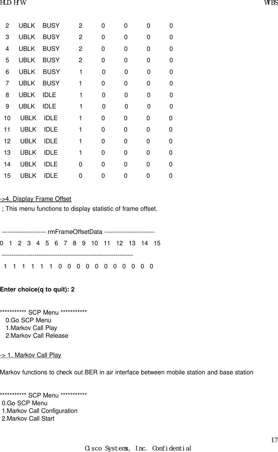
![HLD-H/W WIBS 16 Cisco Systems, Inc. Confidential -> 1. Display CDPC data ; This menu enables to show the status of CDPC(Digital Channel Card) like bellows CeID] CeType, Equip, Block, Status, Use, FrameO, Walsh --------------------------------------------------------------------------------- 0 : PSA EQP UBLK NORM BUSY 255 0 1 : PCE EQP UBLK NORM BUSY 255 1 2 : TCE EQP UBLK NORM BUSY 0 20 3 : TCE EQP UBLK NORM BUSY 1 21 4 : TCE EQP UBLK NORM BUSY 2 22 5 : TCE EQP UBLK NORM BUSY 3 23 6 : TCE EQP UBLK NORM BUSY 4 24 7 : TCE EQP UBLK NORM BUSY 5 25 8 : TCE EQP UBLK NORM IDLE 255 255 9 : TCE EQP UBLK NORM IDLE 255 255 10 : TCE EQP UBLK NORM IDLE 255 255 11 : TCE EQP UBLK NORM IDLE 255 255 12 : TCE EQP UBLK NORM IDLE 255 255 13 : TCE EQP UBLK NORM IDLE 255 255 14 : TCE EQP UBLK NORM IDLE 255 255 15 : TCE EQP UBLK NORM IDLE 255 255 -> 2. Display Using TCE ; This menu displays the traffic channel which is using currently ------------ Used Channel Element Status ------------ TceTotalCnt[14] TceNormalCnt [14] TceAllocCnt[6] [CeID] Equip, Block, Status, FrameO, Walsh --------------------------------------------------------------------- 0 : EQP UBLK NORM BUSY 255 0 1 : EQP UBLK NORM BUSY 255 1 2 : EQP UBLK NORM BUSY 0 20 3 : EQP UBLK NORM BUSY 1 21 4 : EQP UBLK NORM BUSY 2 22 5 : EQP UBLK NORM BUSY 3 23 6 : EQP UBLK NORM BUSY 4 24 7 : EQP UBLK NORM BUSY 5 25 -> 3. Display TCE Status ; This menu displays the status of traffic channel and statistics of call processing. --------------------------- rmTceData ---------------------------- CeId] Block, Status, ALLOCNT, ABNCNT, NOMSACK, NOBSACK, RESCNT -------------------------------------------------------------------](https://usermanual.wiki/Cisco-Systems/MWIBS1900/User-Guide-152813-Page-16.png)
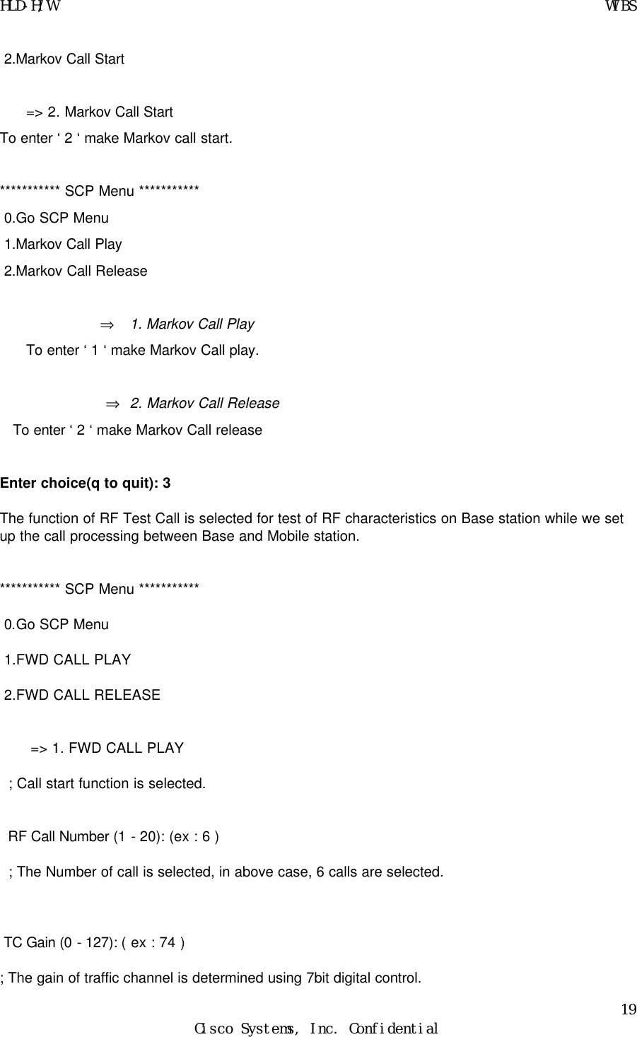
![HLD-H/W WIBS 18 Cisco Systems, Inc. Confidential => 1.Markov Call Configuration This menu enables Markov call process and display sub_menu like below. *********** SCP Menu *********** 0.Go Markov Menu 1.IMSI select 2.Service Option Select 3.Input Data rate 4.Input ESN ⇒ 1. IMSI Select We may designate the phone number to test the base station using mobile station. Ex) IMSI> 4088940001 ⇒ 2. Service Option Select We may choose the quality of service such as 8K or 13K. Ex) Service Option (0: 8K, 1: 13K)> 1 ⇒ 3. Input Data rate We may select Input data rate like belows. *********** SCP Menu *********** SC] Input Data Rate : 1 0. Return 1. Eight Rate 2. Quarter Rate 3. Half Rate 4. FUll Rate 5. Variable Rate ⇒ 4. Input ESN To identify mobile station, we may use ESN of mobile station. Ex) SC] Input ESN (1234abcd): 1234abcd Go to Markov Call Start Menu if we enter ‘ 0 ‘ *********** SCP Menu *********** 0.Go SCP Menu 1.Markov Call Configuration](https://usermanual.wiki/Cisco-Systems/MWIBS1900/User-Guide-152813-Page-18.png)
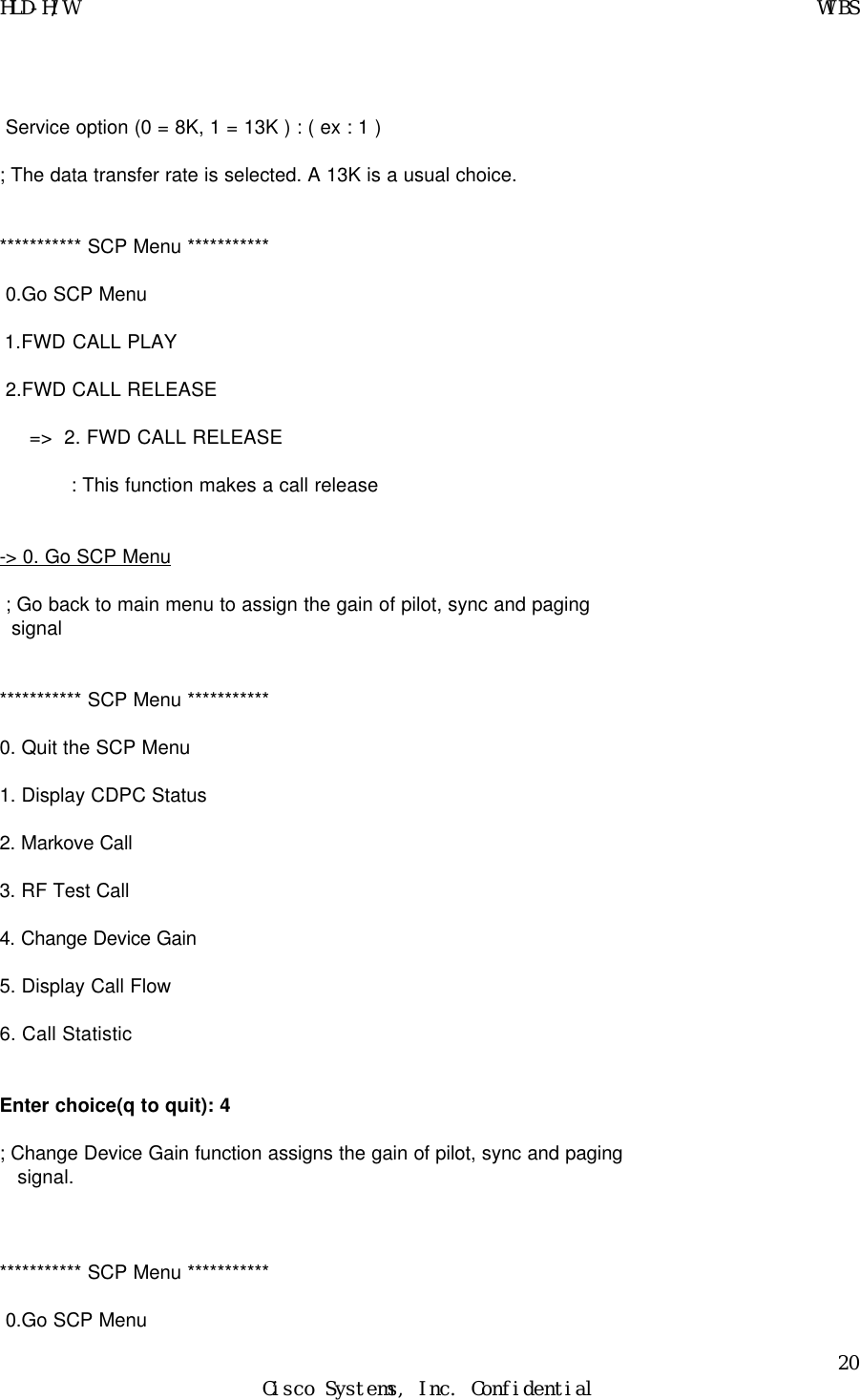
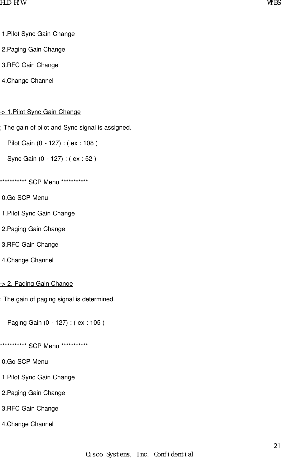
![HLD-H/W WIBS 22 Cisco Systems, Inc. Confidential -> 3.RFC Gain Change ; The output power of transmitted RF signal can be controlled. RFCX Gain (0 - 127) : ( ex : 52 ) [RFCX] TxAtt: 5.2dB ; The RF power is attenuated. Normally 15dB is setup as attenuation. *********** SCP Menu *********** 0.Go SCP Menu 1.Pilot Sync Gain Change 2.Paging Gain Change 3.RFC Gain Change 4.Change Channel -> 4.Change Channel : A Channel number to assign frequency in use can be specified by typing in, for example, 25, 300, 377 Enter choice(q to quit): 5 ; For debugging purpose, we may use this menu to print out the status of system on the monitor screen. *********** SCP Menu *********** 0.Go SCP Menu 1.Configuration Display 2.Call Display 3.Handoff Display 4.Registration Display 5.Status Display 6.Error Display -> 1. Configuration Display](https://usermanual.wiki/Cisco-Systems/MWIBS1900/User-Guide-152813-Page-22.png)
![HLD-H/W WIBS 23 Cisco Systems, Inc. Confidential ; It make us monitor the initialization of each component such as CDPC, RFC, and GPS. If we enter ‘1’, then CM is on, one more entry make it off. Ex) SC] CM ON -> 2. Call Display ; We may monitor the call process with printing out the call process status on the screen. It is the same way as Configuration Display. Ex) SC] Call On -> 3. Handoff Display ; The procedure of Handoff process can be monitored by this menu. Ex) SC] HO ON -> 4. Registration Display ; The Registration also can be monitored by this menu. Ex) SC] Reg ON -> 5. Status Display ; The status related system resource can be monitored by this menu. Ex) SC] Status ON -> 6. Error Display ; The Error can be monitored by this menu. Ex) SC] ERR ON Enter choice(q to quit): 6 A Statistic related with Call will be displayed by this menu.](https://usermanual.wiki/Cisco-Systems/MWIBS1900/User-Guide-152813-Page-23.png)