Cisco Systems TEI301W IP Managed Services Home Gateway User Manual
Cisco Systems Inc IP Managed Services Home Gateway
User Manual

4038767 Rev A
Cisco Managed Services
Residential Gateway
User Guide
Please Read
Important
Please read this entire guide. If this guide provides installation or operation
instructions, give particular attention to all safety statements included in this guide.
Notices
Trademark Acknowledgments
Cisco and the Cisco Logo are trademarks of Cisco Systems, Inc. and/or its affiliates
in the U.S. and other countries. A listing of Cisco's trademarks can be found at
www.cisco.com/go/trademarks.
Third party trademarks mentioned are the property of their respective owners.
The use of the word partner does not imply a partnership relationship between
Cisco and any other company. (1005R)
The Wi-Fi Protected Setup mark is a mark of the Wi-Fi Alliance. Wi-Fi Protected
Setup is a trademark of the Wi-Fi Alliance. <<WRITERS: Use this statement if your
product and document uses the WPS (Wi-Fi Protected Setup) logo. You MUST
also include a wireless product disclaimer (Object 137283) in your doc.>>
Disclaimer
The maximum performance for wireless is derived from IEEE Standard 802.11
specifications. Actual performance can vary, including lower wireless network
capacity, data throughput rate, range and coverage. Performance depends on many
factors, conditions and variables, including distance from the access point, volume of
network traffic, building materials and construction, operating system used, mix of
wireless products used, interference and other adverse conditions.
Publication Disclaimer
Cisco Systems, Inc. assumes no responsibility for errors or omissions that may
appear in this publication. We reserve the right to change this publication at any
time without notice. This document is not to be construed as conferring by
implication, estoppel, or otherwise any license or right under any copyright or
patent, whether or not the use of any information in this document employs an
invention claimed in any existing or later issued patent.
Copyright
© 2010 Cisco Systems, Inc. All rights reserved. Printed in the United States of America.
Information in this publication is subject to change without notice. No part of this
publication may be reproduced or transmitted in any form, by photocopy,
microfilm, xerography, or any other means, or incorporated into any information
retrieval system, electronic or mechanical, for any purpose, without the express
permission of Cisco Systems, Inc.
Notice to Installers
The servicing instructions in this notice are for use by qualified service personnel only. To reduce the
risk of electric shock, do not perform any servicing other than that contained in the operating
instructions, unless you are qualified to do so.
Notice à l’attention des installateurs de réseaux câblés
Les instructions relatives aux interventions d’entretien, fournies dans la présente notice, s’adressent
exclusivement au personnel technique qualifié. Pour réduire les risques de chocs électriques, n’effectuer
aucune intervention autre que celles décrites dans le mode d'emploi et les instructions relatives au
fonctionnement, à moins que vous ne soyez qualifié pour ce faire.
Mitteilung für CATV-Techniker
Die in dieser Mitteilung aufgeführten Wartungsanweisungen sind ausschließlich für qualifiziertes
Fachpersonal bestimmt. Um die Gefahr eines elektrischen Schlags zu reduzieren, sollten Sie keine
Wartungsarbeiten durchführen, die nicht ausdrücklich in der Bedienungsanleitung aufgeführt sind,
außer Sie sind zur Durchführung solcher Arbeiten qualifiziert.
Aviso a los instaladores de sistemas CATV
Las instrucciones de reparación contenidas en el presente aviso son para uso exclusivo por parte de
personal de mantenimiento cualificado. Con el fin de reducir el riesgo de descarga eléctrica, no realice
ninguna otra operación de reparación distinta a las contenidas en las instrucciones de funcionamiento, a
menos que posea la cualificación necesaria para hacerlo.
20080814_Installer800_Intl
4038767 Rev A iii
Contents
Notice à l’attention des installateurs de réseaux câblés ........................................ 5
Mitteilung für CATV-Techniker ............................................................................... 5
Aviso a los instaladores de sistemas CATV ............................................................ 6
IMPORTANT SAFETY INSTRUCTIONS vii
Power Source Warning ........................................................................................... vii
Ground the Product ................................................................................................. vii
Protect the Product from Lightning ..................................................................... viii
Verify the Power Source from the On/Off Power Light ................................... viii
Eliminate AC Mains Overloads ............................................................................ viii
Provide Ventilation and Select a Location .......................................................... viii
Protect from Exposure to Moisture and Foreign Objects .................................. viii
Service Warnings ....................................................................................................... ix
Check Product Safety ................................................................................................ ix
Protect the Product When Moving It ...................................................................... ix
Telephone Equipment Notice .................................................................................. ix
United States FCC Compliance xii
Declaration of Conformity ....................................................................................... xii
Canada EMI Regulation ........................................................................................... xii
RF Exposure Statements .........................................................................................xiii
CE Compliance xvi
Declaration of Conformity with Regard to the EU Directive
1999/5/EC (R&TTE Directive) ........................................................................... xvi
National Restrictions ............................................................................................. xvii
Antennas ................................................................................................................ xviii
About This Guide xix
Introduction .............................................................................................................. xix
Audience ................................................................................................................... xix
Related Publications ................................................................................................ xix
Document Version ................................................................................................... xix
Chapter 1 Introducing the Managed Services Residential Gateway1
Benefits and Features............................................................................................................... 2
Personal Content Sharing and Storage .................................................................... 2
Simplified Connected Home ..................................................................................... 2
Contents
iv 4038767 Rev A
Phone Services ............................................................................................................. 2
Wireless Services ......................................................................................................... 3
Home Security, Monitoring and Automation ......................................................... 3
Web Browsing supported with Parental Controls & Firewall
Monitoring ................................................................................................................ 4
Home Energy Management ...................................................................................... 4
Simplified Support ...................................................................................................... 4
What's on the Top Panel? ........................................................................................................ 5
What's on the Back Panel? ...................................................................................................... 7
What's on the Side Panel? ....................................................................................................... 8
What's on the Bottom Panel ................................................................................................... 9
Chapter 2 Installing the Residential Gateway 11
Mounting the Residential Gateway ..................................................................................... 12
Mounting the Residential Gateway Horizontally ................................................ 12
Mounting the Residential Gateway Vertically ..................................................... 12
Connecting the Residential Gateway .................................................................................. 15
Chapter 3 Configuration and Operation of the the Residential
Gateway 19
Logging into the Residential Gateway ................................................................................ 20
Internet .................................................................................................................................... 21
VoIP Settings........................................................................................................................... 25
SIP ............................................................................................................................... 25
Service ......................................................................................................................... 26
Voice ........................................................................................................................... 28
Advanced ................................................................................................................... 29
Call Log ...................................................................................................................... 30
Wi-Fi ........................................................................................................................................ 32
Home Address ........................................................................................................................ 34
Media Storage ......................................................................................................................... 35
Chapter 4 Using the LCD 37
Get Familiar with the LCD Screens and Menus ................................................................ 38
Internet .................................................................................................................................... 41
Phone ....................................................................................................................................... 42
Wi-Fi ........................................................................................................................................ 44
Turn Wi-Fi Off or On ................................................................................................ 44
Initiate Wi-Fi Protection Setup ................................................................................ 45
Ports ......................................................................................................................................... 48
Tools ......................................................................................................................................... 49
Review Your Emergency 911 Address .................................................................. 49
Perform Factory Reset .............................................................................................. 51
Contents
4038767 Rev A v
Select Language Settings .......................................................................................... 52
View Network Information ..................................................................................... 53
Use Network Tools ................................................................................................... 55
View Router Information ......................................................................................... 57
Select LCD Display Orientation .............................................................................. 58
View System Event Log ........................................................................................... 59
Set Up Time of Day Parameters .............................................................................. 60
Chapter 5 Customer Information 63
Customer Support .................................................................................................................. 64
If You Have Questions ............................................................................................. 64
Additional Information ............................................................................................ 65
Return Products for Repair ................................................................................................... 66

IMPORTANT SAFETY INSTRUCTIONS
4038767 Rev A vii
IMPORTANT SAFETY INSTRUCTIONS
1)
Read these instructions.
2)
Keep these instructions.
3)
Heed all warnings.
4)
Follow all instructions.
5)
Do not use this apparatus near water.
6)
Clean only with dry cloth.
7)
Do not block any ventilation openings. Install in accordance with the manufacturer's
instructions.
8)
Do not install near any heat sources such as radiators, heat registers, stoves, or other
apparatus (including amplifiers) that produce heat.
9)
Do not defeat the safety purpose of the polarized or grounding-type plug. A
polarized plug has two blades with one wider than the other. A grounding-type
plug has two blades and a third grounding prong. The wide blade or the third
prong are provided for your safety. If the provided plug does not fit into your
outlet, consult an electrician for replacement of t
he obsolete outlet.
10)
Protect the power cord from being walked on or pinched particularly at plugs,
convenience receptacles, and the point where they exit from the apparatus.
11)
Only use attachments/accessories specified by the manufacturer.
12)
Use only with the cart, stand, tripod, bracket, or table specified by the
manufacturer, or sold with the apparatus. When a cart is used, use caution
when moving the cart/apparatus combination to avoid injury from
tip-over.
13)
Unplug this apparatus during lightning storms or when unused for long periods of
time.
14)
Refer all servicing to qualified service personnel. Servicing is required when the
apparatus has been damaged in any way, such as a power-supply cord or plug is
damaged, liquid has been spilled or objects have fallen into the apparatus, the
apparatus has been exposed to rain or moisture, does not operate normally, or has
been dropped.
Power Source Warning
A label on this product indicates the correct power source for this product. Operate this product only
from an electrical outlet with the voltage and frequency indicated on the product label. If you are
uncertain of the type of power supply to your home or business, consult your service provider or your
local power company.
The AC inlet on the unit must remain accessible and operable at all times.
Ground the Product
WARNING: Avoid electric shock and fire hazard! If this product connects to coaxial
cable wiring, be sure the cable system is grounded (earthed). Grounding provides
some protection against voltage surges and built-up static charges.
IMPORTANT SAFETY INSTRUCTIONS
viii 4038767 Rev A
Protect the Product from Lightning
In addition to disconnecting the AC power from the wall outlet, disconnect the signal inputs.
Verify the Power Source from the On/Off Power Light
When the on/off power light is not illuminated, the apparatus may still be connected to the power
source. The light may go out when the apparatus is turned off, regardless of whether it is still plugged
into an AC power source.
Eliminate AC Mains Overloads
WARNING: Avoid electric shock and fire hazard! Do not overload AC mains, outlets,
extension cords, or integral convenience receptacles. For products that require battery
power or other power sources to operate them, refer to the operating instructions for
those products.
Provide Ventilation and Select a Location
Remove all packaging material before applying power to the product.
Do not place this apparatus on a bed, sofa, rug, or similar surface.
Do not place this apparatus on an unstable surface.
Do not install this apparatus in an enclosure, such as a bookcase or rack, unless the installation
provides proper ventilation.
Do not place entertainment devices (such as VCRs or DVDs), lamps, books, vases with liquids, or
other objects on top of this product.
Do not block ventilation openings.
Protect from Exposure to Moisture and Foreign Objects
WARNING: Avoid electric shock and fire hazard! Do not expose this product to
dripping or splashing liquids, rain, or moisture. Objects filled with liquids, such as
vases, should not be placed on this apparatus.
WARNING: Avoid electric shock and fire hazard! Unplug this product before cleaning.
Do not use a liquid cleaner or an aerosol cleaner. Do not use a magnetic/static cleaning
device (dust remover) to clean this product.
WARNING: Avoid electric shock and fire hazard! Never push objects through the
openings in this product. Foreign objects can cause electrical shorts that can result in
electric shock or fire.

IMPORTANT SAFETY INSTRUCTIONS
4038767 Rev A ix
Service Warnings
WARNING: Avoid electric shock! Do not open the cover of this product. Opening or
removing the cover may expose you to dangerous voltages. If you open the cover, your
warranty will be void. This product contains no user-serviceable parts.
Check Product Safety
Upon completion of any service or repairs to this product, the service technician must perform safety
checks to determine that this product is in proper operating condition.
Protect the Product When Moving It
Always disconnect the power source when moving the apparatus or connecting or disconnecting
cables.
Telephone Equipment Notice
When using your telephone equipment, basic safety precautions should always be followed to reduce
the risk of fire, electric stock and injury to persons, including the following:
1. Do not use this product near water, for example, near a bath tub, wash bowl, kitchen sink or laundry
tub, in a wet basement or near a swimming pool.
2. Avoid using a telephone (other than a cordless type) during an electrical storm. There may be a
remote risk of electric shock from lightning.
3. Do not use the telephone to report a gas leak in the vicinity of the leak.
CAUTION: To reduce the risk of fire, use only No. 26 AWG or larger
telecommunication line cord.
SAVE THESE INSTRUCTIONS
20090915_Modem No Battery_Safety
IMPORTANT SAFETY INSTRUCTIONS
4038767 Rev A xi

United States FCC Compliance
xii 4038767 Rev A
United States FCC Compliance
This device has been tested and found to comply with the limits for a Class B digital device,
pursuant to part 15 of the FCC Rules. These limits are designed to provide reasonable
protection against such interference in a residential installation. This equipment generates,
uses, and can radiate radio frequency energy. If not installed and used in accordance with the
instructions, it may cause harmful interference to radio communications. However, there is
no guarantee that interference will not occur in a particular installation. If this equipment
does cause harmful interference to radio or television reception, which can be determined by
turning the equipment OFF and ON, the user is encouraged to try to correct the interference
by one or more of the following measures:
Reorient or relocate the receiving antenna.
Increase the separation between the equipment and receiver.
Connect the equipment into an outlet on a circuit different from that to which the
receiver is connected.
Consult the service provider or an experienced radio/television technician for help.
Any changes or modifications not expressly approved by Cisco Systems, Inc., could void the
user's authority to operate the equipment.
The information shown in the FCC Declaration of Conformity paragraph below is a
requirement of the FCC and is intended to supply you with information regarding the FCC
approval of this device. The phone numbers listed are for FCC-related questions only and not
intended for questions regarding the connection or operation for this device. Please contact your
service provider for any questions you may have regarding the operation or installation of this device.
Declaration of Conformity
This device complies with Part 15 of FCC
Rules. Operation is subject to the following
two conditions: 1) the device may not cause
harmful interference, and 2) the device must
accept any interference received, inc
luding
interference that may cause undesired
operation.
Cisco® Managed Services Residential
Gateway
Model(s): REN301,
REN301W, REN301Z,
TEI301, TEI301W, TEI301Z, TES301,
TES301W, TES301Z
Manufactured by:
Cisco Systems, Inc.
5030 Sugarloaf Parkway
Lawrenceville, Georgia 30044 USA
Telephone: 770-236-1077
Canada EMI Regulation
This Class B digital apparatus complies with Canadian ICES-003.
Cet appareil numérique de la class B est conforme à la norme NMB-003 du Canada.
United States FCC Compliance
4038767 Rev A xiii
RF Exposure Statements
Note: This transmitter must not be co-located or operated in conjunction with any other
antenna or transmitter. This equipment should be installed and operated with a minimum
distance of 7.9 inches (20 cm) between the radiator and your body.
US
This system has been evaluated for RF exposure for humans in reference to ANSI C 95.1
(American National Standards Institute) limits. The evaluation was based in accordance with
FCC OET Bulletin 65C rev 01.01 in compliance with Part 2.1091 and Part 15.27. The minimum
separation distance from the antenna to general bystander is 7.9 inches (20 cm) to maintain
compliance.
Canada
This system has been evaluated for RF exposure for humans in reference to Canada Health
Code 6 (2009) limits. The evaluation was based on evaluation per RSS-102 Rev 4. The
minimum separation distance from the antenna to general bystander is 7.9 inches (20 cm) to
maintain compliance.
EU
This system has been evaluated for RF exposure for humans in reference to the ICNIRP
(International Commission on Non-Ionizing Radiation Protection) limits. The evaluation was
based on the EN 50385 Product Standard to Demonstrate Compliance of Radio Base Stations
and Fixed Terminals for Wireless Telecommunications Systems with basic restrictions or
reference levels related to Human Exposure to Radio Frequency Electromagnetic Fields from
300 MHz to 40 GHz. The minimum separation distance from the antenna to general
bystander is 20 cm (7.9 inches).
Australia
This system has been evaluated for RF exposure for humans as referenced in the Australian
Radiation Protection standard and has been evaluated to the ICNIRP (International
Commission on Non-Ionizing Radiation Protection) limits. The minimum separation distance
from the antenna to general bystander is 20 cm (7.9 inches).
20100527 FCC DSL_Dom and Intl

Canada
This device complies with RSS-210 of the Industry Canada Rules. Operation is subject to the following two conditions: (1)
This device may not cause harmful interference, and (2) this device must accept any interference received, including
interference that may cause undesired operation.
Ce dispositif est conforme à la norme CNR-210 d'Industrie Canada applicable aux appareils radio exempts de licence. Son
fonctionnement est sujet aux deux conditions suivantes: (1) le dispositif ne doit pas produire de brouillage préjudiciable, et
(2) ce dispositif doit accepter tout brouillage reçu, y compris un brouillage susceptible de provoquer un fonctionnement
indésirable.
IMPORTANT NOTE:
Radiation Exposure Statement:
This equipment complies with IC radiation exposure limits set forth for an uncontrolled environment. This
equipment should be installed and operated with minimum distance 20cm between the radiator & your body.
NOTE IMPORTANTE:
Déclaration d'exposition aux radiations:
Cet équipement est conforme aux limites d'exposition aux rayonnements IC établies pour un environnement non
contrôlé. Cet équipement doit être installé et utilisé avec un minimum de 20 cm de distance entre la source de
rayonnement et votre corps.
United States FCC Compliance
4038767 Rev A xv

CE Compliance
xvi 4038767 Rev A
CE Compliance
Declaration of Conformity with Regard to the EU Directive 1999/5/EC
(R&TTE Directive)
This declaration is only valid for configurations (combinations of software, firmware and
hardware) supported or provided by Cisco Systems for use within the EU. The use of
software or firmware not supported or provided by Cisco Systems may result in the
equipment no longer being compliant with the regulatory requirements.

CE Compliance
4038767 Rev A xvii
Note: The full declaration of conformity for this product can be found in the Declarations of
Conformity and Regulatory Information section of the appropriate product hardware
installation guide, which is available on Cisco.com.
The following standards were applied during the assessment of the product against the
requirements of the Directive 1999/5/EC:
Radio: EN 300 328
EMC: EN 301 489-1 and EN 301 489-17
Safety: EN 60950 and EN 50385
The CE mark and class-2 identifier are affixed to the product and its packaging. This product
conforms to the following European directives:
-
1999/5/EC
National Restrictions
This product is for indoor use only.
France
For 2.4 GHz, the output power is restricted to 10 mW EIRP when the product is used
outdoors in the band 2454 - 2483,5 MHz. There are no restrictions when used in other parts of
the 2,4 GHz band. Check http://www.arcep.fr/ for more details.
Pour la bande 2,4 GHz, la puissance est limitée à 10 mW en p.i.r.e. pour les équipements
utilisés en extérieur dans la bande 2454 - 2483,5 MHz. Il n'y a pas de restrictions pour des
utilisations dans d'autres parties de la bande 2,4 GHz. Consultez http://www.arcep.fr/ pour
de plus amples détails.
Italy
This product meets the National Radio Interface and the requirements specified in the
National Frequency Allocation Table for Italy. Unless this wireless LAN product is operating
within the boundaries of the owner's property, its use requires a “general authorization.”
Please check http://www.comunicazioni.it/it/ for more details.
Questo prodotto è conforme alla specifiche di Interfaccia Radio Nazionali e rispetta il Piano
Nazionale di ripartizione delle frequenze in Italia. Se non viene installato all 'interno del
proprio fondo, l'utilizzo di prodotti Wireless LAN richiede una “Autorizzazione Generale”.
Consultare http://www.comunicazioni.it/it/ per maggiori dettagli.
Latvia
The outdoor usage of the 2.4 GHz band requires an authorization from the Electronic
Communications Office. Please check http://www.esd.lv for more details.
2,4 GHz frekvenču joslas izmantošanai ārpus telpām nepieciešama atļauja no Elektronisko
sakaru direkcijas. Vairāk informācijas: http://www.esd.lv.
Note: The regulatory limits for maximum output power are specified in EIRP. The EIRP level
of a device can be calculated by adding the gain of the antenna used (specified in dBi) to the
output power available at the connector (specified in dBm).
CE Compliance
xviii 4038767 Rev A
Antennas
Use only the antenna supplied with the product.
20090312 CE_Gateway
About This Guide
4038767 Rev A xix
About This Guide
Introduction
This guide supports the Cisco® Managed Services Residential Gateway. Refer to
this guide for installing and configuring your residential gateway.
Models supported by this guide include:
REN301 Managed Services Residential Gateway
TES301 Managed Services Residential Gateway with SIP
TEI301 Managed Services Residential Gateway with SIP/IMS
REN301WManaged Services Residential Gateway with Z-Wave
TES301W Managed Services Residential Gateway with Z-Wave with SIP
TEI301W Managed Services Residential Gateway with Z-Wave with SIP/IMS
REN301Z Managed Services Residential Gateway with ZigBee
TES301Z Managed Services Residential Gateway with ZigBee with SIP
TEI301Z Managed Services Residential Gateway with ZigBee with SIP/IMS
Audience
This document is written for residential subscribers using a Managed Services
Residential Gateway.
Related Publications
Visit our website (https://www.sciatl.com/subscriberextranet/techpubs) to view
additional publications about our products.
You need a user name and password to access this website. If you do not have a user
name and password, go to
https://www.scientificatlanta.com/dsnexplorer/register.htm to complete and
submit a registration form.
Note: You may need to install a PDF reader, such as Adobe Acrobat Reader, on your
system to view these publications.
Document Version
This is the first formal release of this document.
About This Guide
xx 4038767 Rev A

4038767 Rev A 1
Introduction
The Cisco
® Managed Services Residential Gateway is an advanced,
high
-
performance home gateway that combines Ethernet, Voice over
IP (VoIP), router and wireless access point technologies
in a single
device providing a cost
-effective voice and networking solution for
Connected Home and Managed Home experiences.
This chapter lists the benefits and features of the
residential gateway
.
Illustrations and descriptions of the connection ports, power and reset
buttons, touch-sensitive keys, and LED indicators are also provided.
1 Chapter 1
Introducing the Managed
Services Residential Gateway
In This Chapter
Benefits and Features ............................................................................. 2
What's on the Top Panel?....................................................................... 5
What's on the Back Panel? ..................................................................... 7
What's on the Side Panel? ...................................................................... 8
What's on the Bottom Panel .................................................................. 9

Chapter 1 Introducing the Managed Services Residential Gateway
2 4038767 Rev A
Benefits and Features
Personal Content Sharing and Storage
Digital Living Network Alliance (DLNA) support provides a consolidated view
of all content within the home network
Content can be shared with any PC or device connected to the home network
Pre-Installed SD card can support up to 32 GB capacity for local, intelligent
caching of digital video, pictures, music and other files.
Supports streaming content to media players and TVs
Remote Access using Managed Service applications allows access to content
from outside the home via a laptop or PDA
Remote notifications for event triggering applications
Optional IPSec for tunneling data to remote Storage servers
Optional DTCP-IP security for copyright protected music and video files
Simplified Connected Home
Easy to use and follow color LCD combined with Embedded Network
Management to simplify connections, configurations & settings of IP devices in
the home
Supports remote management, proactive monitoring and software updates
Supports secure WAN tunnels for private/protected personal data flows
Supports 10/100/1000 Ethernet WAN for deployment behind xDSL, fiber and
cable modems, 3G/4G WAN option via USB datacard or embedded module
Easy wireless setup with WPS Push Button
Phone Services
2 ATA Ports with SIP Client support separate SIP phone numbers
Home coverage supports SIP/IMS phones, Wi-Fi connection with Android

Benefits and Features
4038767 Rev A 3
Wireless Services
Wi-Fi 802.11b/g/n 2.4 GHz (2x2) for basic home networking service
Provides Unscheduled Automatic Power Save Delivery (UAPSD) Cell phone
handoff (SIP) support
Internal Antenna designs supports omni-directional and beam forming
techniques that provide excellent 3-D coverage, isolation & pattern diversity in
all bands
Home Security, Monitoring and Automation
Managed Services (OSGi/JVM, iControl, 4-Home, Open Peak, etc.)
Remote home management from work or while traveling allows
arming/disarming of home security system, lighting control, thermostat control,
door lock control, and live video monitoring
The REN301W, TEI301W, and TES301W models function as primary controller
to include a Zwave node to the network by assigning its Home ID and Node ID
and exclude other Zwave nodes as well. Characteristics for this low-power
wireless technology used by home control, monitoring and security include:
- RF Frequency band: Sub-GHz
- Mesh Networking: Every node is a repeater and self healing
- 32-bit unique identifier as Home ID to separate Z-wave networks
- An 8-bit identifier called the Node ID is used to address individual nodes in
the same network. One Z-wave network can have up to 232 nodes
The REN301Z, TEI301Z, and TES301Z models support ZigBee, which is a
technology for wireless sensors and control networks based on the IEEE 802.15.4
standard. ZigBee can be used for home automation/control and energy
management, such as light switch, light dimmer, door lock, thermostat, and
smart meter, etc. The characteristics of ZigBee are listed below:
- RF frequency band: 2.4GHz
- Data rates of 250kbps
- Range: 50m typical (5-500m based on environment)
- Multiple topologies: star, peer-to-peer, mesh
- 64-bit IEEE address
Internal Antenna designs supports omni-directional techniques that provide
excellent 3-D coverage, isolation & pattern diversity in all bands.
Chapter 1 Introducing the Managed Services Residential Gateway
4 4038767 Rev A
Web Browsing supported with Parental Controls & Firewall Monitoring
NAPT, SPI firewall, WEP, WPA/2, MAC filtering, and VPN pass-through,
IPv4 + IPv6, VLAN IEEE 802.1q and p
Comprehensive protocol support including IGMP, DLNA, UPnP and OSGi/JVM
friendly
Remote Management via TR-069, TR-104 and embedded Network Management
Home Energy Management
Home Area Network (HAN) and an energy management service which enables
more optimal use of energy by consumers
Simplified Support
Setup – Embedded Network Management and Provisioning tool simplifies
installation of the residential gateway.
Network Manager – a PC based application that helps to self-manage the home
network (repairs connections, secures, facilitates sharing)
What's on the Top Panel?
4038767 Rev A 5
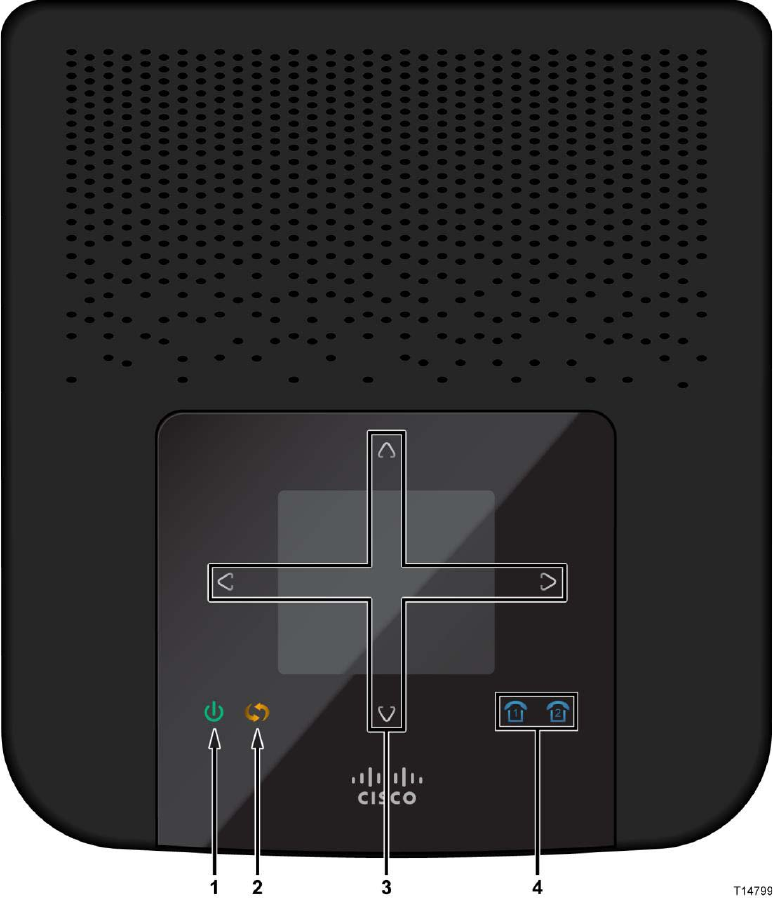
What's on the Top Panel?
The top panel of your residential gateway provides an LCD screen for easy setup
and configuration. Use the touch-sensitive arrow keys to navigate through the menu
options. Refer to Configuration and Operation of the the Residential Gateway (on
page 19) for more information on this feature. The top panel also provides LED
status icons that indicate the operational state of your gateway. Refer to the
following diagram for a description of the top panel.
Chapter 1 Introducing the Managed Services Residential Gateway
6 4038767 Rev A
1 Power (Green/Red)—The Power LED lights up when the residential gateway is
powered on.The LED becomes red during a malfunction.
2 WPS Touch-Sensitive Key (Amber)—Touch for 3 seconds to initiate pairing
with Wi-Fi devices.
3 LCD with Touch-Sensitive Keys—LCD screen lights up by the wave of a hand
to display menu options for common setup and configuration functions. The
touch-sensitive keys, indicated by the up, down, left, and right arrows, help you
navigate through the menus.
4 Phone 1-2 (Blue)—The LED lights up blue when it is registered with SIP server.
It flashes to indicate voice mail messages have been received.
What's on the Back Panel?
4038767 Rev A 7
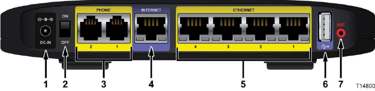
What's on the Back Panel?
The back panel of your residential gateway provides ports, power, and reset
mechanisms. Refer to the following diagram for a description of the back panel.
1 Power—The Power port is where you will connect the power adapter that is
included in the box.
2 Power Switch—Use this switch to power on or off the device.
3 Phone 1-2—The Phone ports connect standard analog telephones to the device.
4 Internet—The Internet port connects to the Ethernet port on the DSL, fiber, or
cable modem.
5 Ethernet LAN 1-4—These Ethernet ports (1, 2, 3, 4) connect device to wired
computers and other Ethernet network devices.
6 USB—The USB port connects to a USB storage device, such as a USB hard drive
or flash disk.
7 Reset—The Reset button restores the device to its original factory settings by
pressing and holding down the Reset button for 5 seconds.
Note: The reset does not restore the voice settings to the factory defaults.
Chapter 1 Introducing the Managed Services Residential Gateway
8 4038767 Rev A
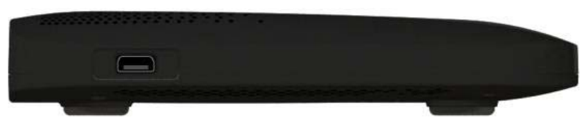
What's on the Side Panel?
The side panel of your residential gateway provides an additional USB port. Refer to
the following diagram for a description of the back panel.
USB—The USB port connects to a USB storage device, such as a USB hard drive or
flash disk.
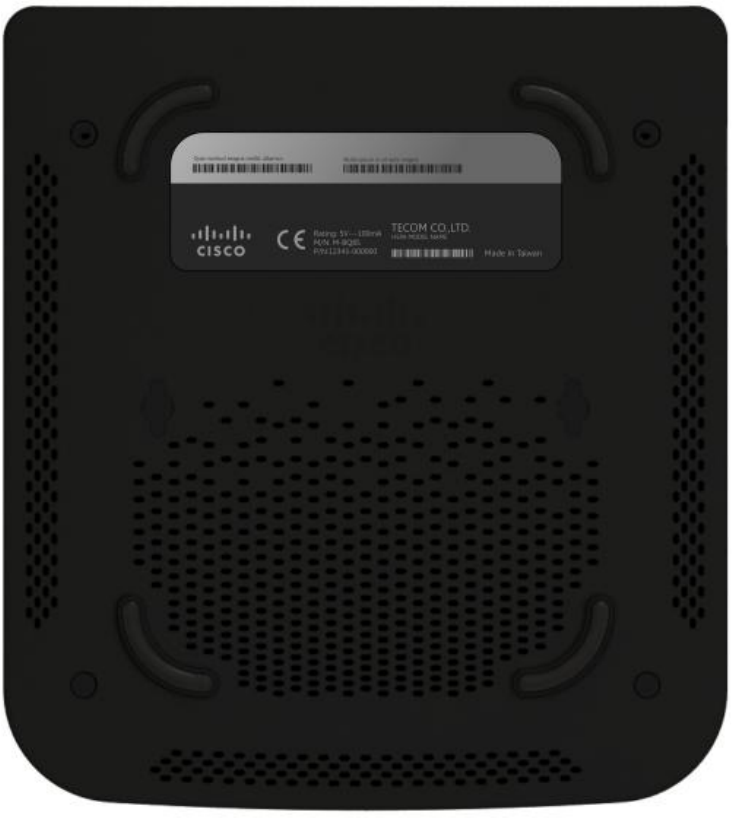
What's on the Bottom Panel
4038767 Rev A 9
What's on the Bottom Panel
The bottom panel of your residential gateway provides holes for mounting screws
for wall mounting and protective feet for vertical or wall mounting surfaces. The
factory label on the bottom panel provides serial number and MAC Address
information.

4038767 Rev A 11
Introduction
This chapter provides instructions for installing the residential
gateway.
2 Chapter 2
Installing the Residential
Gateway
In This Chapter
Mounting the Residential Gateway .................................................... 12
Connecting the Residential Gateway ................................................. 15
Chapter 2 Installing the Residential Gateway
12 4038767 Rev A
Mounting the Residential Gateway
Mounting the Residential Gateway Horizontally
The residential gateway has four rubber feet on its bottom panel. Place the
residential gateway on a level surface near an electrical outlet.
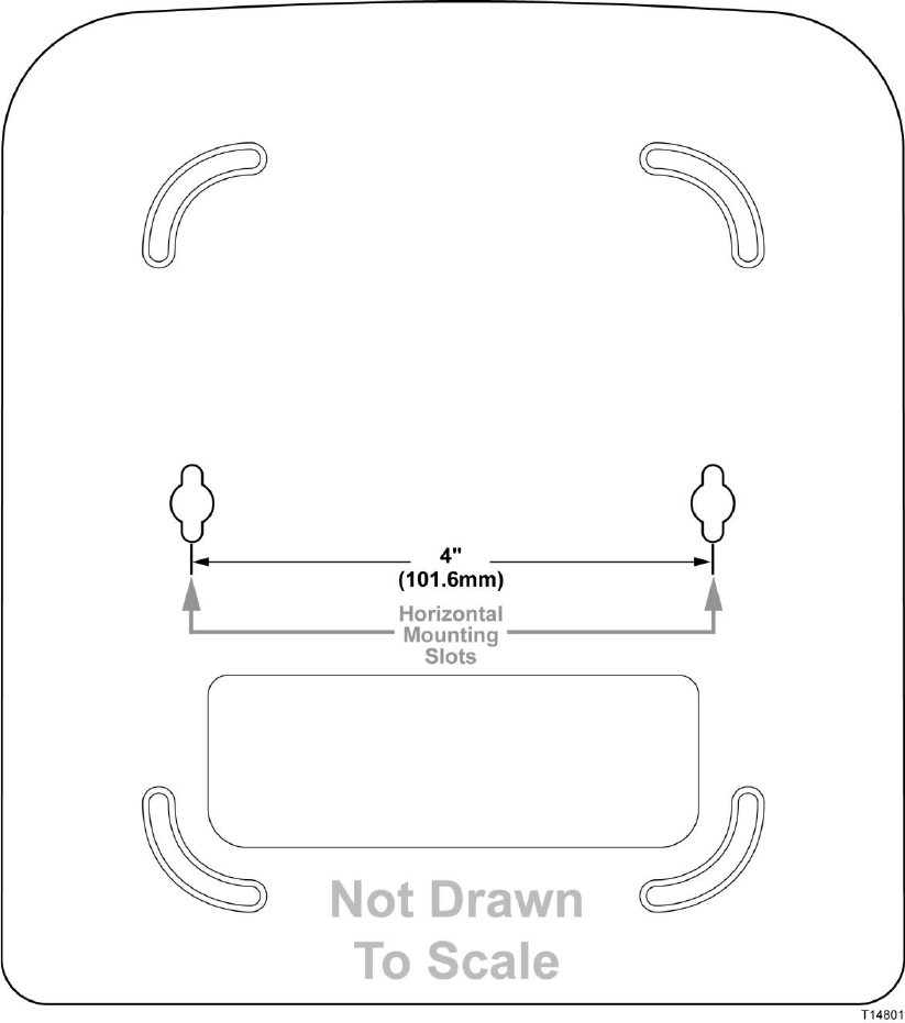
Mounting the Residential Gateway Vertically
The residential gateway has four wall-mount slots on its bottom panel. The distance
between two adjacent slots is 4 inches (101.6 mm).
Two screws are needed to mount the residential gateway.
Mounting the Residential Gateway
4038767 Rev A 13
The following illustration shows the location and dimensions of the wall-mounting
slots on the bottom of the residential gateway. Use the information on this page as a
guide for mounting your residential gateway to the wall.
Notes:
Mounting hardware illustrations are not true to scale.
Cisco is not responsible for damages incurred by insecure wall-mounting
hardware.
Chapter 2 Installing the Residential Gateway
14 4038767 Rev A
Follow these instructions:
1 Determine where you want to mount the residential gateway. Make sure that the
wall you use is smooth, flat, dry, and sturdy. Also make sure the location is
within reach of an electrical outlet.
2 Drill two holes into the wall. Make sure the holes are 4 inches (101.6 mm) apart.
3 Insert a screw into each hole and leave 2 mm (0.8 inches) below the head
exposed.
4 Maneuver the residential gateway so two of the wall-mount slots line up with
the two screws.
5 Place the wall-mount slots over the screws and slide the residential gateway
down until the screws fit snugly into the wall-mount slots.
Connecting the Residential Gateway
4038767 Rev A 15
Connecting the Residential Gateway
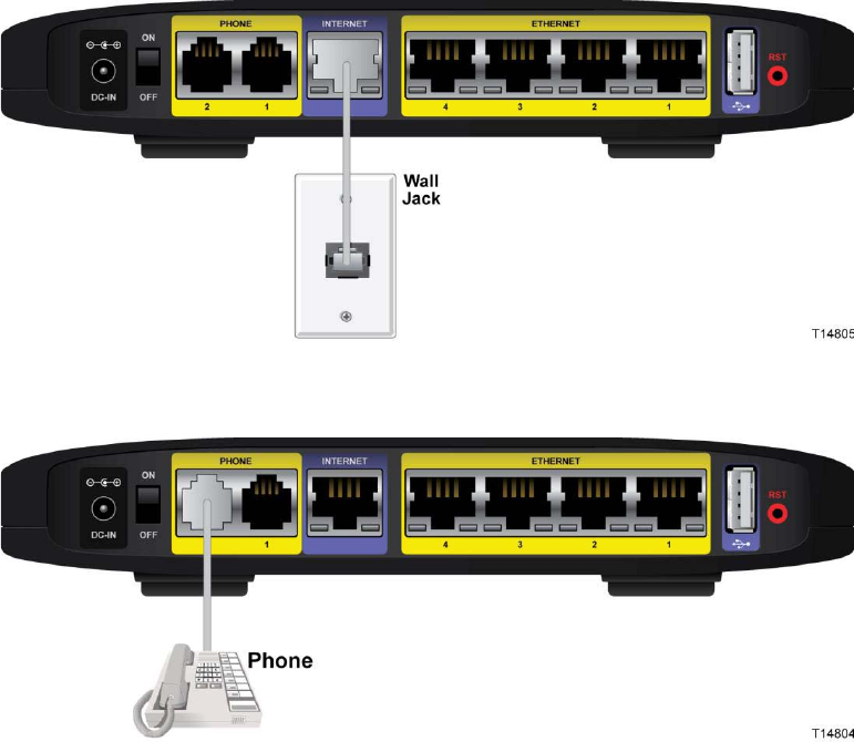
Perform the following steps to connect the residential gateway.
1 Insert a standard RJ-45 Ehternet cable (included) into the Internet port and
connect the other end to an xDSL, cable modem, or other Internet device.
2 Insert a standard RJ-11 telephone cable into the PHONE 1 port and connect the
other end to an analog touchtone telephone.
3 (Optional) You can connect the PHONE 2 port to a second analog telephone or a
fax machine.
Note: To prevent an invalid connection to the circuit switched Telco network, do
not connect an RJ-11 telephone cable from the PHONE 1 (or PHONE 2) port on
the residential gateway to the wall jack.
Chapter 2 Installing the Residential Gateway
16 4038767 Rev A
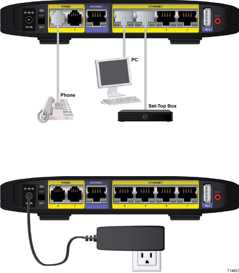
4 (Optional) Connect a PC or other Ethernet device to an ETHERNET port using a
standard RJ-45 Ethernet cable.
5 Connect the included power adapter to the residential gateway power port, and
then plug the power adapter into an electrical outlet. The power LED on the
front panel will light up as soon as the device powers on.
6 Power on the residential gateway. The LCD will light up with a message that the
device is booting up.
Connecting the Residential Gateway
4038767 Rev A 17
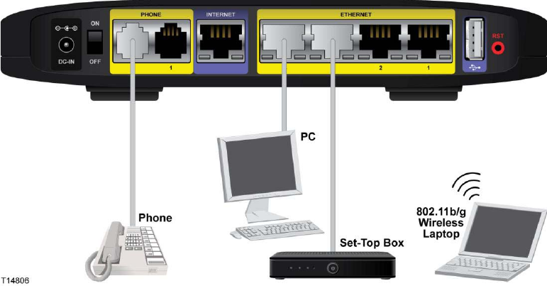
7 Follow the instructions in your owner's manual for your PC or laptop to activate
the wireless connection.
Note: A wireless connection requires a wireless-enabled notebook or a computer
with an 802.11b/g/n wireless network adapter installed.
8 Continue with the Configuration and Operation of the the Residential Gateway
(on page 19) chapter to configure your residential gateway.

4038767 Rev A 19
Introduction
This chapter provides instructions to use the web
-based utility to set
up connections and configure the residential gateway features.
3 Chapter 3
Configuration and Operation
of the the Residential Gateway
In This Chapter
Logging into the Residential Gateway............................................... 20
Internet ................................................................................................... 21
VoIP Settings ......................................................................................... 25
Wi-Fi ....................................................................................................... 32
Home Address ...................................................................................... 34
Media Storage ........................................................................................ 35
Chapter 3 Configuration and Operation of the the Residential Gateway
20 4038767 Rev A
Logging into the Residential Gateway
Complete the following steps to access the web-based utility.
Note: If the residential gateway was supplied by your service provider, then it may
restrict access to the web-based utility. Contact your service provider for the login
information.
1 Launch the web browser on your computer.
2 Type 192.168.29.1 in the URL Address field. This value is the residential
gateway's default IP address.
3 Press Enter. A login screen appears.
4 Is this the first time you have opened the web-based utility?
If yes, type admin in the User name and Password fields.
If no, enter the user name and password you established previously.
5 Click OK to continue. The web-based utility opens.
6 To continue setup, go to the section applicable for your desired configuration:
Internet
4038767 Rev A 21
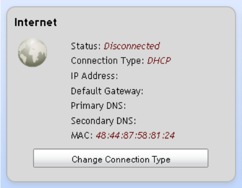
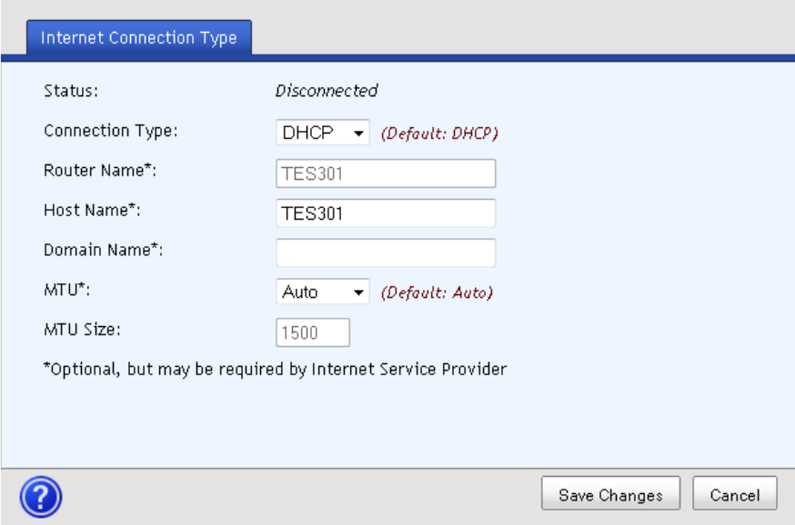
Internet
You will need to select a specific type of connection for your Internet connection.
Your selection will determine which additional parameters will be required to
complete your configuration.
Complete the following steps to set up your Internet connection.
1 From the residential gateway dashboard, click the Change Connection Type
button located in the Internet cell.
Chapter 3 Configuration and Operation of the the Residential Gateway
22 4038767 Rev A
2 Select an option from the Connection Type drop-down menu.
3 Complete the fields for the connection type you selected as follows:
For all connection types:
– Router Name—
– Host Name—Enter the Host Name of your internet server
– Domain Name—Enter the Domain Name of your local network
– MTU—Select Auto or Manual
– MTU Size—Keep this value in the 1200 to 1500 range. The default MTU
is configured automatically.
For a Static connection:
Note: Your service provider may provide static Internet IP address, subnet
mask, and default gateway values.
– Internet IP Address—Enter the Gateway’s IP address, as seen from the
Internet.
– Subnet Mask—Enter the Gateway’s Subnet Mask, as seen from the
Internet (including your service provider)
– Default Gateway—Enter the IP address of the service provider’s server
– DNS 1 through DNS 3—Enter the DNS (Domain Name System) server IP
address(es) provided by your service provider. At least one is required.
For a PPPoE connection:
Internet
4038767 Rev A 23
– Username and Password—Enter the Username and Password provided
by your service provider.
– Connect on Demand—You can configure the Router to cut the Internet
connection after it has been inactive for a specified period of time (Max
Idle Time). If your Internet connection has been terminated due to
inactivity, Connect on Demand enables the Router to automatically re-
establish your connection as soon as you attempt to access the Internet
again
– Max Idle Time—Enter the number of minutes you want to have elapsed
before your Internet connection terminates. The default Max Idle Time is
5 minutes.
For a PPTP connection:
– Internet IP Address—Enter the Gateway’s IP address, as seen from the
Internet
– Subnet Mask—Enter the Gateway’s Subnet Mask, as seen from the
Internet (including your service provider)
– Gateway—Enter the IP address of the service provider’s server
– Username and Password—Enter the Username and Password provided
by your service provider.
– Connect on Demand—You can configure the Router to cut the Internet
connection after it has been inactive for a specified period of time (Max
Idle Time). If your Internet connection has been terminated due to
inactivity, Connect on Demand enables the Router to automatically re-
establish your connection as soon as you attempt to access the Internet
again
– Max Idle Time—Enter the number of minutes you want to have elapsed
before your Internet connection terminates. The default Max Idle Time is
5 minutes.
For an L2TP connection:
– Username and Password—Enter the Username and Password provided
by your service provider.
– L2TP Server IP—Enter the IP address of the L2TP server
– Connect on Demand—You can configure the Router to cut the Internet
connection after it has been inactive for a specified period of time (Max
Idle Time). If your Internet connection has been terminated due to
inactivity, Connect on Demand enables the Router to automatically re-
establish your connection as soon as you attempt to access the Internet
again
– Max Idle Time—Enter the number of minutes you want to have elapsed
before your Internet connection terminates. The default Max Idle Time is
5 minutes.
Chapter 3 Configuration and Operation of the the Residential Gateway
24 4038767 Rev A
4 Click Save Changes to save the information or Cancel to return to the
dashboard.

VoIP Settings
4038767 Rev A 25
VoIP Settings
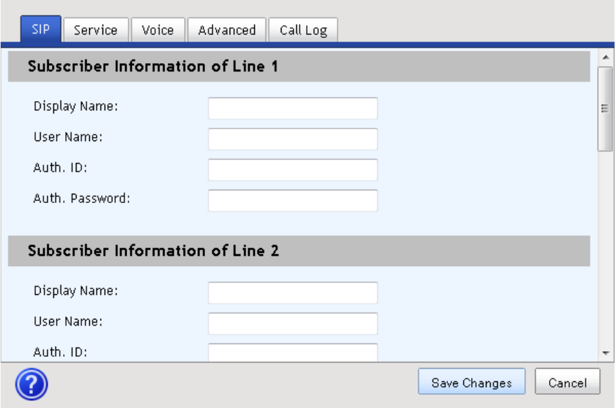
SIP
Complete the following steps to configure the SIP parameters for your VoIP settings.
1 From the residential gateway dashboard, click the Change Settings button
located in the VoIP Settings cell.
2 Complete the fields for the SIP tab.
Chapter 3 Configuration and Operation of the the Residential Gateway
26 4038767 Rev A
3 Click Save Changes to save the information or Cancel to return to the
dashboard.
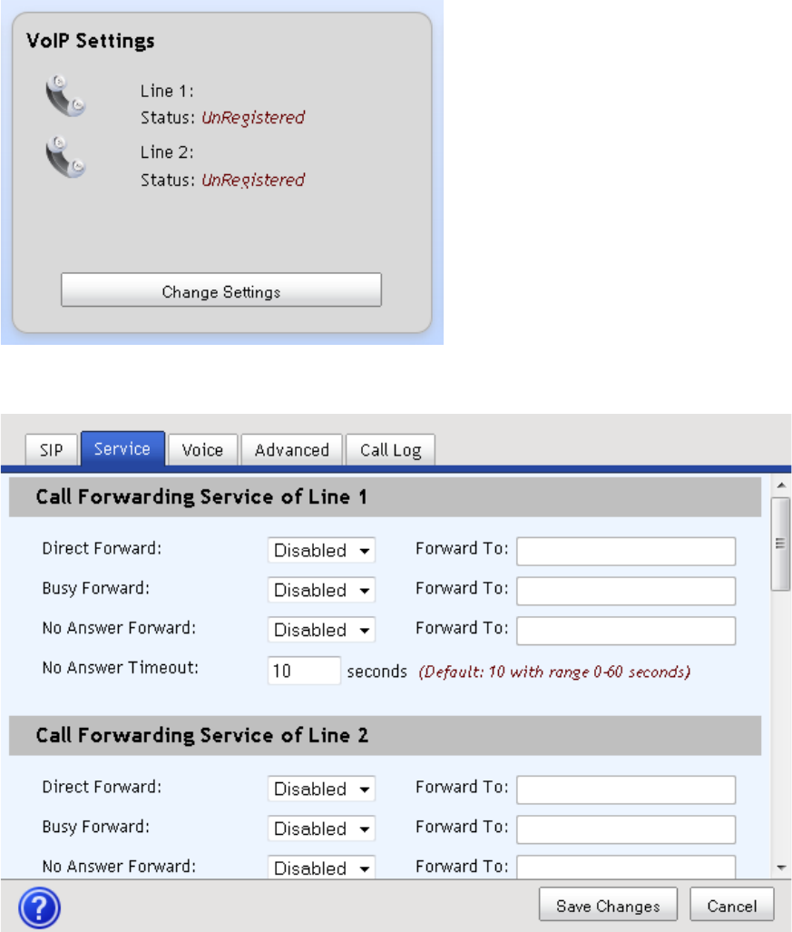
Service
Complete the following steps to configure the Service parameters for your VoIP
settings.
VoIP Settings
4038767 Rev A 27
1 From the residential gateway dashboard, click the Change Settings button
located in the VoIP Settings cell.
2 Complete the fields for the Service tab.
3 Click Save Changes to save the information or Cancel to return to the
dashboard.
Chapter 3 Configuration and Operation of the the Residential Gateway
28 4038767 Rev A
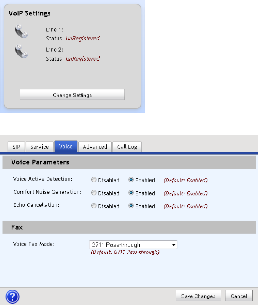
Voice
Complete the following steps to configure the Voice parameters for your VoIP
settings.
1 From the residential gateway dashboard, click the Change Settings button
located in the VoIP Settings cell.
2 Complete the fields for the Voice tab.
3 Click Save Changes to save the information or Cancel to return to the
dashboard.
VoIP Settings
4038767 Rev A 29
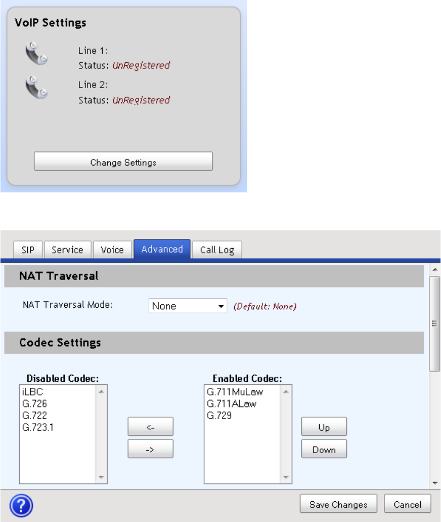
Advanced
1 From the residential gateway dashboard, click the Change Settings button
located in the VoIP Settings cell.
2 Complete the fields for the Advanced tab.
Chapter 3 Configuration and Operation of the the Residential Gateway
30 4038767 Rev A
3 Click Save Changes to save the information or Cancel to return to the
dashboard.
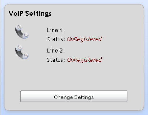
Call Log
Complete the following steps to review the Call Log for your VoIP usage.
1 From the residential gateway dashboard, click the Change Settings button
located in the VoIP Settings cell.
VoIP Settings
4038767 Rev A 31
2 Click the Call Log tab to view the call history for each line.
3 Click Delete to clear items from the Call Log or Cancel to return to the
dashboard.
Chapter 3 Configuration and Operation of the the Residential Gateway
32 4038767 Rev A
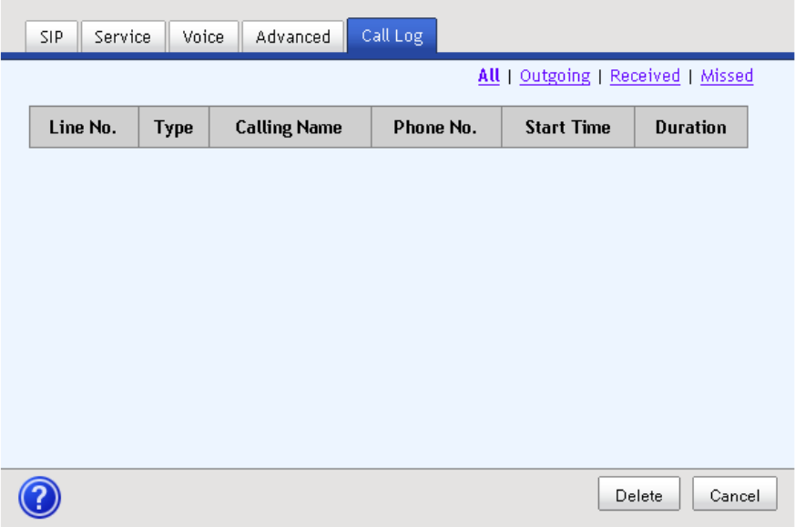
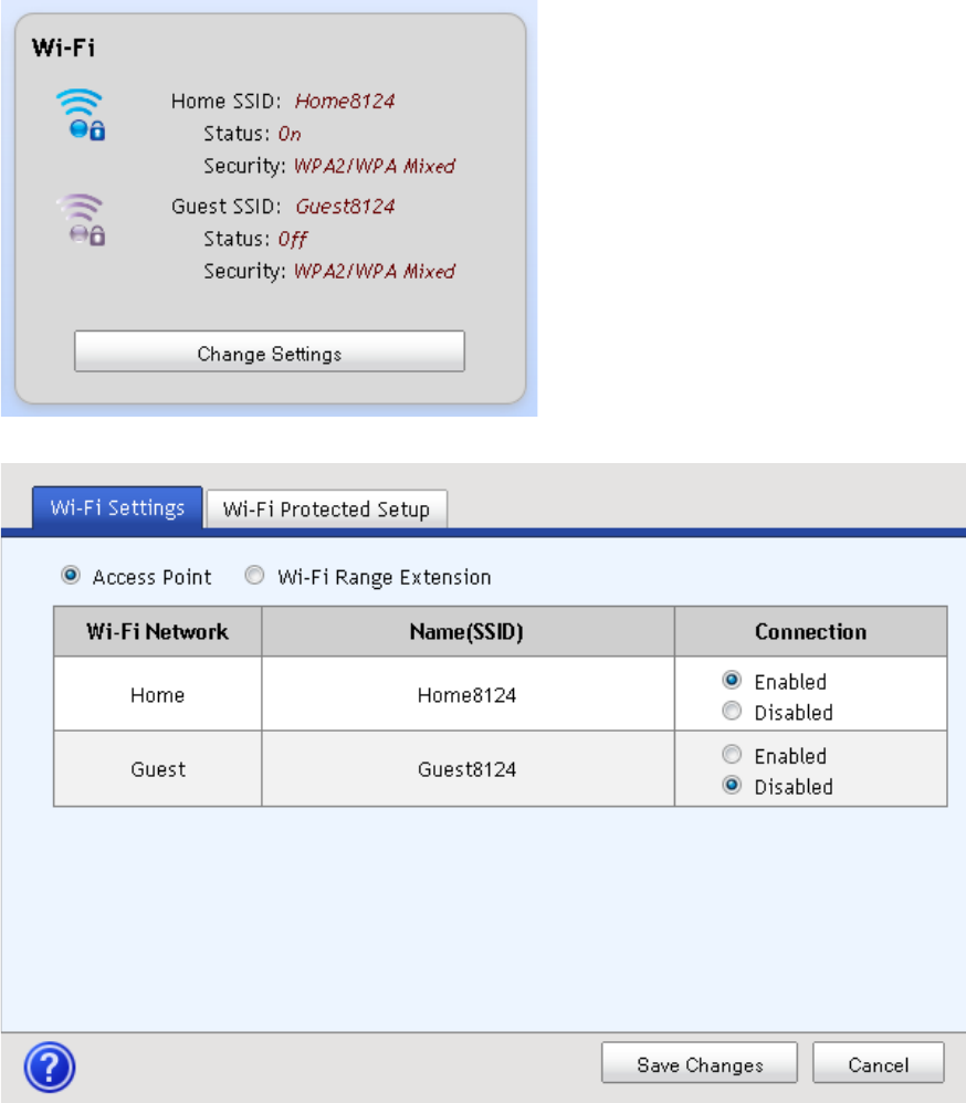
Wi-Fi
1 From the residential gateway dashboard, click the Change Settings button
located in the Wi-Fi cell.
2 Select either the Access Point or Wi-Range Extension options.
3 Complete the fields for the option you selected.
4 Click Save Changes to save the information or Cancel to return to the
dashboard.
Wi-Fi
4038767 Rev A 33
Chapter 3 Configuration and Operation of the the Residential Gateway
34 4038767 Rev A
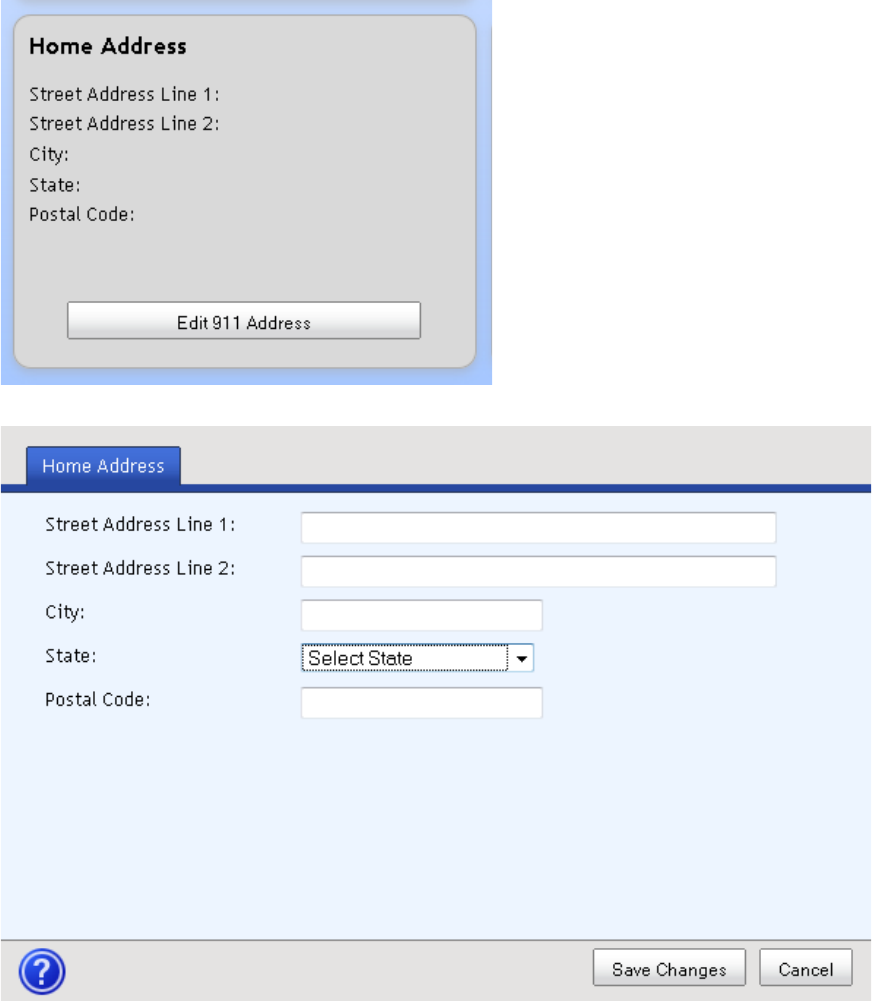
Home Address
1 From the residential gateway dashboard, click the Edit 911 Address button
located in the Home Address cell.
2 Complete the fields on the screen.
3 Click Save Changes to save the information or Cancel to return to the
dashboard.
Media Storage
4038767 Rev A 35
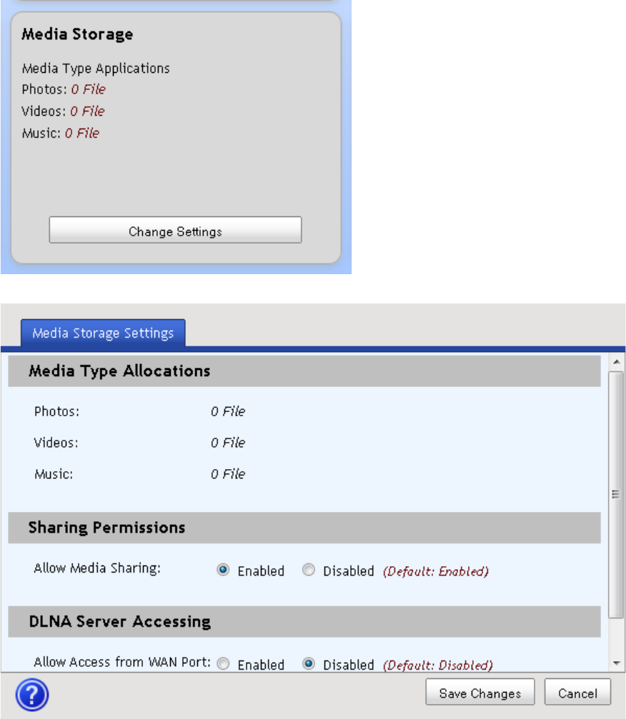
Media Storage
1 From the residential gateway dashboard, click the Change Settings button
located in the Media Storage cell.
2 Complete the fields on the screen.
3 Click Save Changes to save the information or Cancel to return to the
dashboard.

4038767 Rev A 37
Introduction
4 Chapter 4
Using the LCD
In This Chapter
Get Familiar with the LCD Screens and Menus ............................... 38
Internet ................................................................................................... 41
Phone ...................................................................................................... 42
Wi-Fi ....................................................................................................... 44
Ports ........................................................................................................ 48
Tools ........................................................................................................ 49
Chapter 4 Using the LCD
38 4038767 Rev A
Get Familiar with the LCD Screens and Menus
Follow the steps below to navigate to the Home Page and through the subject pages
and menus available from the LCD screen.
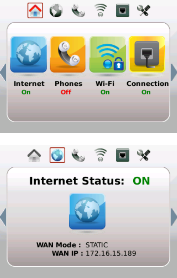
1 Wave your hand over the LCD. The Home page and the touch-sensitive arrow
keys appear. Notice that the House icon is highlighted when the Home page is
displayed. As you page through the LCD screens, the device will highlight the
icon applicable to the pages or menus you are using.
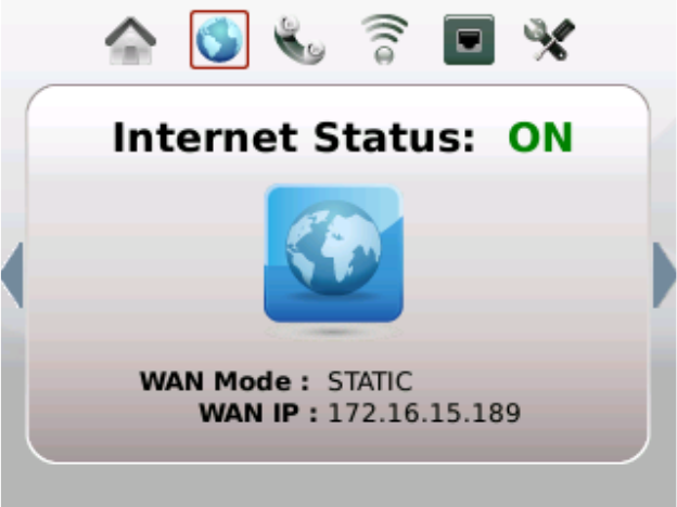
2 Tap the right arrow once and the Internet Status page appears.
4038767 Rev A 39
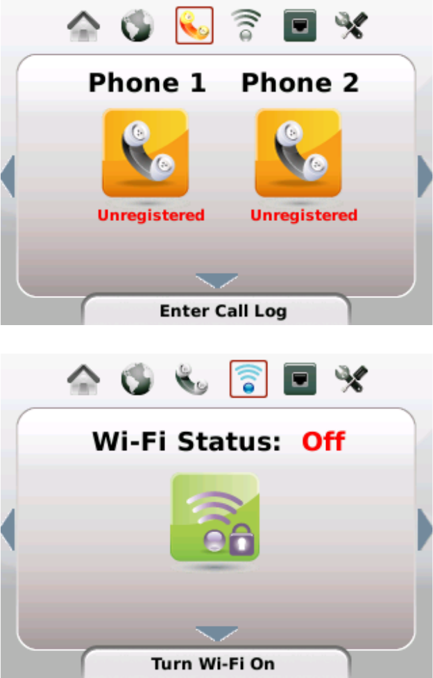
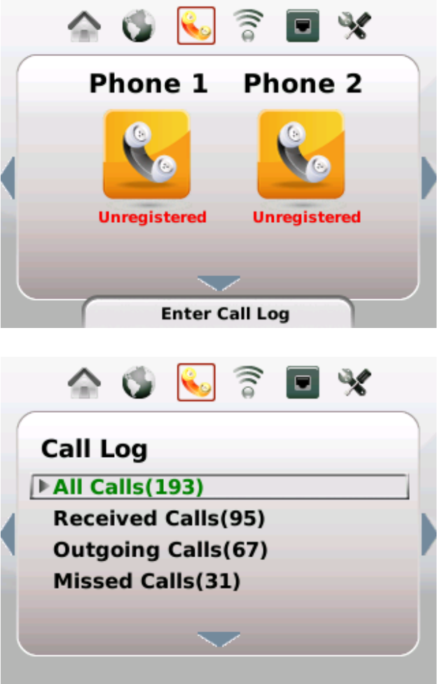
3 Tap the right arrow again and the Phone Status page appears.
4 Tap the right arrow again and the Wi-F Network Status page appears.
Chapter 4 Using the LCD
40 4038767 Rev A
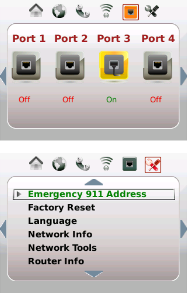
5 Tap the right arrow again and the Ports Status page appears.
6 Tap the right arrow again and the Tools menu appears.
Internet
4038767 Rev A 41
Internet
Follow the steps below to navigate to the Internet Status page.
1 Wave your hand over the LCD.
2 Tap the right arrow repeatedly until the Internet icon is highlighted. The Internet
Status page appears.
3 Tap the left arrow to exit this view.
Chapter 4 Using the LCD
42 4038767 Rev A
Phone
Follow the steps below to navigate to the Phone menus and options.
1 Wave your hand over the LCD.
2 Tap the right arrow repeatedly until the Phone icon is highlighted.
3 Tap the down arrow to display the Call Log menu options.
Note: The number of calls for each category is displayed in parentheses.
4 Tap the down or up arrow to scroll through the menu and highlight the category
you want to view.
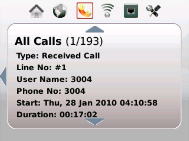
Phone
4038767 Rev A 43
5 Tap the right arrow. The details for the first call in that category appears.
6 Tap the down and up arrows to page through the call details for each call in that
category.
7 Tap the left arrow to exit this view.

Chapter 4 Using the LCD
44 4038767 Rev A
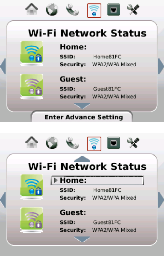
Wi-Fi
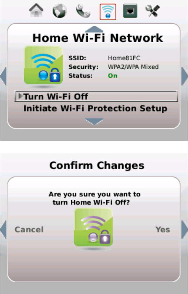
Turn Wi-Fi Off or On
1 Wave your hand over the LCD.
2 Tap the right arrow repeatedly until the Wi-Fi icon is highlighted.
3 Tap the down or up arrow keys to highlight the account you wish to manage.
4 Tap the right arrow. Options for the selected account appear.
Wi-Fi
4038767 Rev A 45
5 Tap the down or up arrow keys to select Turn Wi-Fi Off/On.
6 Tap the right arrow. A confirmation request appears.
7 Tap the right arrow again to accept the change or tap the left arrow to cancel the
request.
8 Tap the left arrow to exit the account details page.
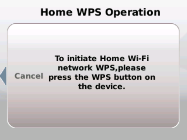
Initiate Wi-Fi Protection Setup
Complete the following steps to initiate Wi-Fi Protection Setup.
Chapter 4 Using the LCD
46 4038767 Rev A
Before you proceed:
At least one account must already be set up. Go to --- to setup account.
Wi-Fi must be turned on for the account you are managing. Go to Turn Wi-Fi Off
or On (on page 44) if Wi-Fi is not already turned on.
1 Wave your hand over the LCD.
2 Tap the right arrow repeatedly until the Wi-Fi icon is highlighted.
3 Tap the down or up arrow keys to highlight the account you wish to manage.
4 Tap the right arrow. Options for the selected account appear.
5 Tap the down or up arrow keys to select Initiate Wi-Fi Protection Setup.
Wi-Fi
4038767 Rev A 47
6 Tap the right arrow. Follow the instructions that appear or tap the left arrow to
cancel the request.
7 When initiation is complete, tap the left arrow to exit this view.
Chapter 4 Using the LCD
48 4038767 Rev A
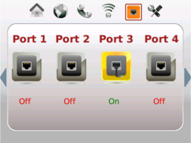
Ports
Follow the steps below to navigate to the Port Status page.
1 Wave your hand over the LCD.
2 Tap the right arrow repeatedly until the Ports icon is highlighted. The Ports
Status page appears.
3 Tap the left arrow to exit this view.
Tools
4038767 Rev A 49
Tools
Follow the steps below to navigate to the Tools menus and options.
1 Wave your hand over the LCD.
2 Tap the right arrow repeatedly until the Tools icon is highlighted.
3 Tap the down arrow to access the Advance Settings menu options.
4 Go to the section for the menu option you wish to use for instructions to use that
option.
Review Your Emergency 911 Address
Complete the following steps to review your Emergency 911 Address information.
1 Wave your hand over the LCD to activate the display.
2 Tap the right arrow repeatedly until the Tools icon is highlighted.

Chapter 4 Using the LCD
50 4038767 Rev A
3 Tap the touch-sensitive down arrow to highlight Emergency 911 Address.
4 Tap the right arrow to view the current Emergency 911 Address information.
Note: Go the following sections in chapter 3 to make changes to this
information:
Logging into the Residential Gateway (on page 20)
Home Address (on page 34)
5 Tap the left arrow to exit this view.
Tools
4038767 Rev A 51
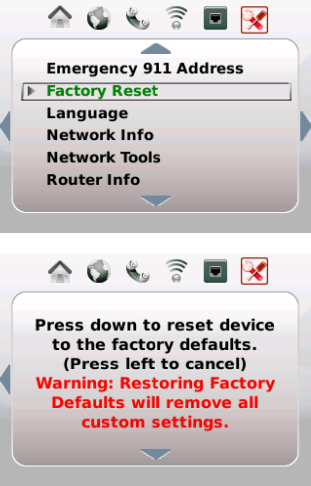
Perform Factory Reset
Complete the following steps to perform a Factory Reset.
1 Wave your hand over the LCD to activate the display.
2 Tap the right arrow repeatedly until the Tools icon is highlighted.
3 Tap the touch-sensitive down arrow to highlight Factory Reset.
4 Tap the right arrow. Instructions to perform a factory reset appear.
Chapter 4 Using the LCD
52 4038767 Rev A
5 Follow the instructions that appear in the LCD screen or tap the left arrow to exit
without making changes.
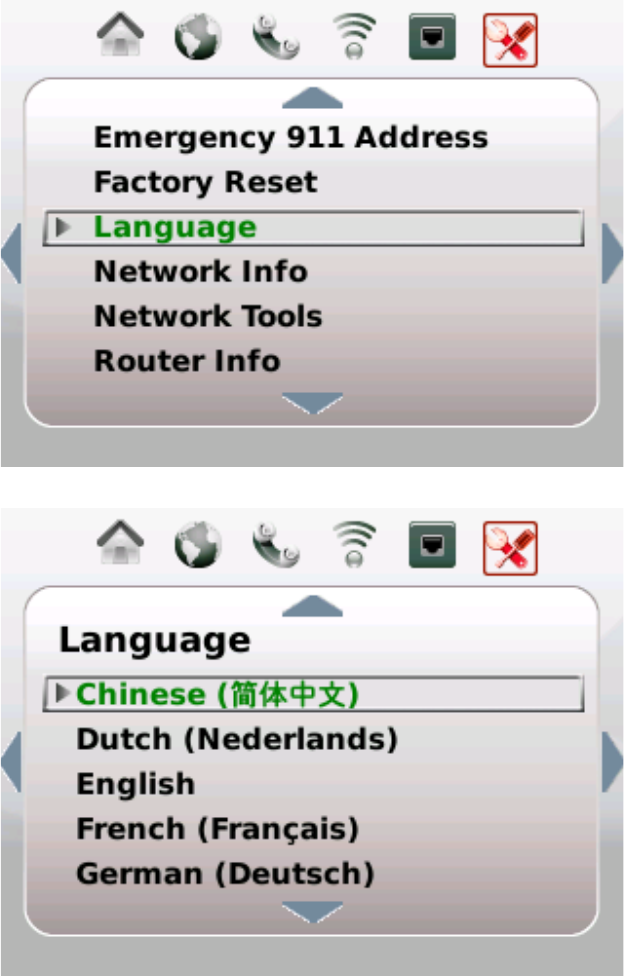
Select Language Settings
Complete the following steps to select your preferred Language.
1 Wave your hand over the LCD to activate the display.
2 Tap the right arrow repeatedly until the Tools icon is highlighted.
3 Tap the touch-sensitive down arrow to highlight Language.
4 Tap the right arrow to view the current language setting.
Tools
4038767 Rev A 53
5 Tap the up or down arrow keys to highlight the language you prefer to appear in
the LCD screens and menus.
6 Tap the right arrow. A confirmation request appears.
7 Tap the right arrow again to accept the change or tap the left arrow to cancel the
request.
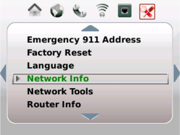
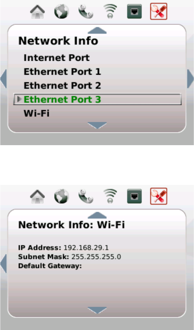
View Network Information
Complete the following steps to view your network information.
1 Wave your hand over the LCD to activate the display.
2 Tap the right arrow repeatedly until the Tools icon is highlighted.
3 Tap the touch-sensitive down arrow to highlight Network Info.
Chapter 4 Using the LCD
54 4038767 Rev A
4 Tap the right arrow. The Network Information menu appears.
5 Tap the up or down arrow keys to highlight the menu option for the information
you want to review.
6 Tap the right arrow. The Network Information page for that menu option
appears.
Note: This information is managed by ---. Contact your service provider to
request/Go to --- and follow the instructions to make changes to this
information.
7 Tap the left arrow to exit this view.
Tools
4038767 Rev A 55
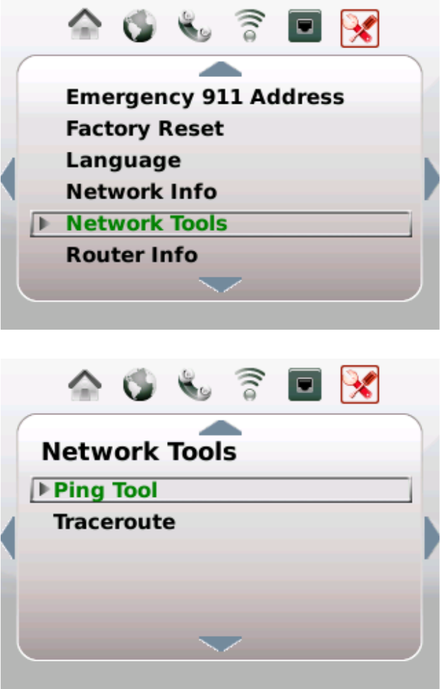
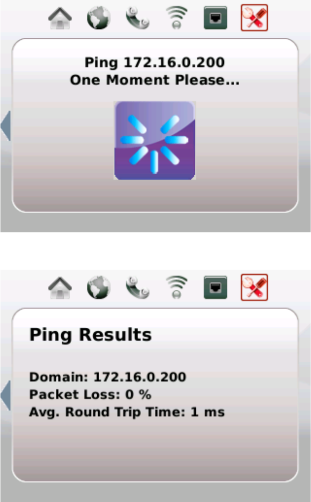
Use Network Tools
Complete the following steps to access and use the Network Tools options.
1 Wave your hand over the LCD to activate the display.
2 Tap the right arrow repeatedly until the Tools icon is highlighted.
3 Tap the touch-sensitive down arrow to highlight Network Tools.
4 Tap the right arrow to view the Network Tools menu options.
5 Tap the up or down arrow keys to highlight the option you want to use.
Chapter 4 Using the LCD
56 4038767 Rev A
6 Tap the right arrow. A request-in-process message appears followed by a results
page.
Ping in Process
Ping Results
7 Tap the left arrow to exit this view.
Tools
4038767 Rev A 57
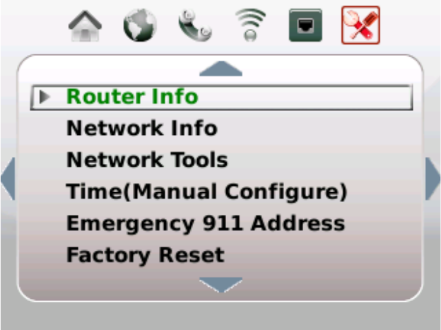
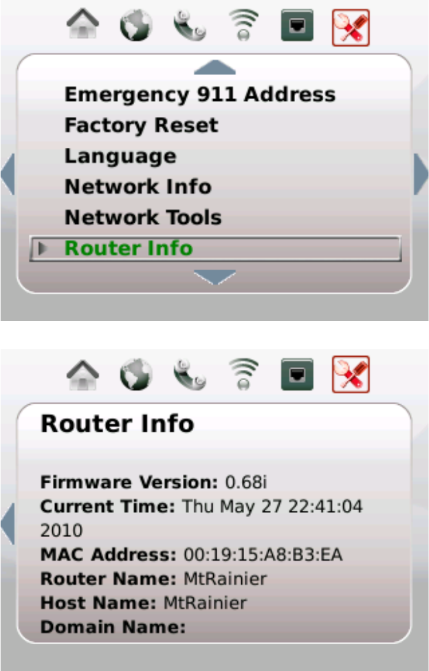
View Router Information
Complete the following steps to view your router information.
1 Wave your hand over the LCD to activate the display.
2 Tap the right arrow repeatedly until the Tools icon is highlighted.
3 Tap the touch-sensitive down arrow to highlight Router Info.
4
5 Tap the right arrow. The Router Information page appears.
Chapter 4 Using the LCD
58 4038767 Rev A
Note: This information is managed by ---. Contact your service provider to
request/Go to --- and follow the instructions to make changes to this
information.
6 Tap the left arrow to exit this view.
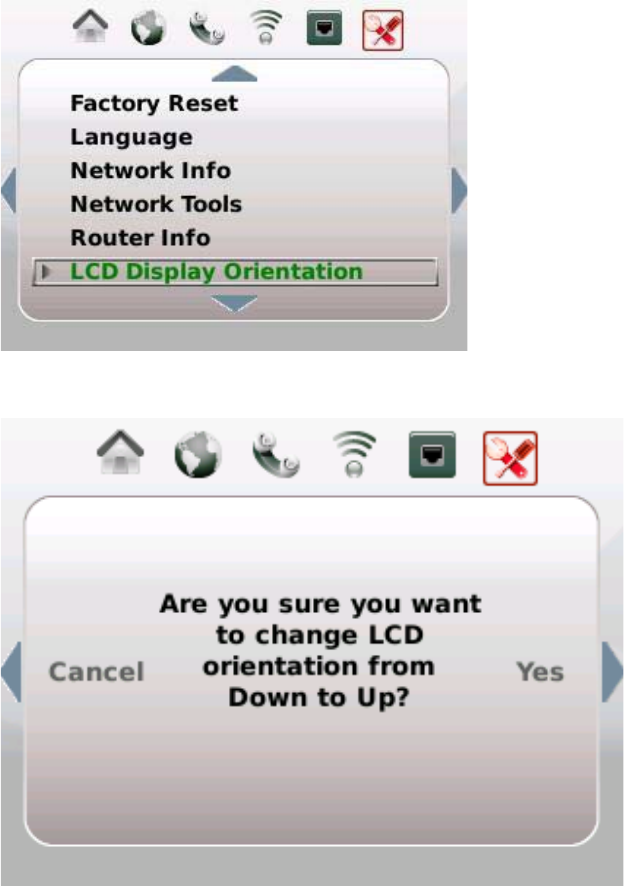
Select LCD Display Orientation
Complete the following steps to select your preferred LCD display orientation.
1 Wave your hand over the LCD to activate the display.
2 Tap the right arrow repeatedly until the Tools icon is highlighted.
3 Tap the touch-sensitive down arrow to highlight LCD Display Orientation.
4 Tap the right arrow to change the current setting. A confirmation request
appears.
Tools
4038767 Rev A 59
5 Tap the right arrow again to accept the change or tap the left arrow to cancel the
request.
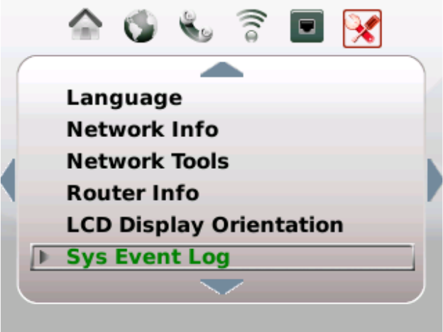
View System Event Log
Complete the following steps to view the system event log.
1 Wave your hand over the LCD to activate the display.
2 Tap the right arrow repeatedly until the Tools icon is highlighted.
3 Tap the touch-sensitive down arrow to highlight Sys Event Log.
Chapter 4 Using the LCD
60 4038767 Rev A
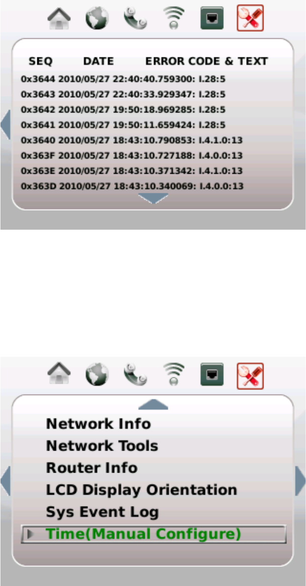
4 Tap the right arrow. The System Event Log page appears.
5 Tap the left arrow to exit this view.
Set Up Time of Day Parameters
Complete the following steps to select your preferred Language.
1 Wave your hand over the LCD to activate the display.
2 Tap the right arrow repeatedly until the Tools icon is highlighted.
3 Tap the touch-sensitive down arrow to highlight Time (Manual Configure).
Tools
4038767 Rev A 61
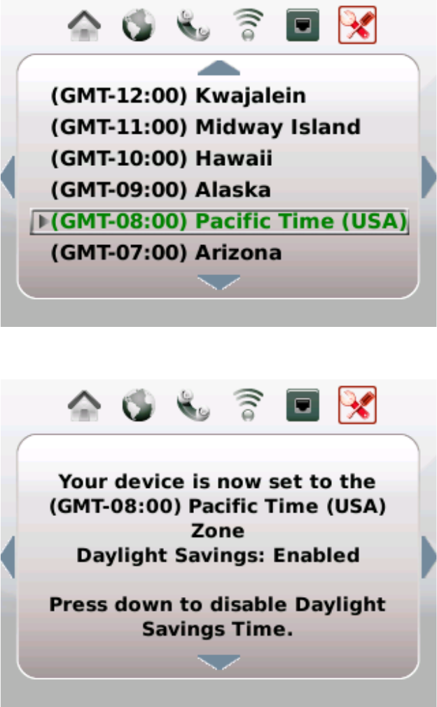
4 Tap the right arrow to view the current time zone setting.
5 Tap the up or down arrow keys to highlight the time zone you prefer to use.
6 Tap the right arrow. A confirmation message appears.
7 (Optional) Tap the down arrow to change the Daylight Savings setting.
8 Tap the left arrow to exit this view.

4038767 Rev A 63
Introduction
This chapter provides contact information to obtain product support
and return products for service.
5 Chapter 5
Customer Information
In This Chapter
Customer Support ................................................................................ 64
Return Products for Repair.................................................................. 66

Chapter 5 Customer Information
64 4038767 Rev A
Customer Support
If You Have Questions
If you have questions about this product, contact the representative who handles
your account for information.
If you have technical questions, telephone your nearest technical support office at
one of the following telephone numbers.
The Americas
United States
Cisco
® Services
Atlanta, Georgia
Technical Support
For Digital Broadband Delivery System
products
only, call:
– Toll-free: 1-866-787-3866
– Local: 770-236-2200
– Fax: 770-236-2488
For all products other than Digital Broadband
Delivery System, call:
– Toll-free: 1-800-722-2009
– Local: 678-277-1120
– Fax: 770-236-2306
Customer Service
Toll-free: 1-800-722-2009
Local: 678-277-1120
Fax: 770-236-5477
The United Kingdom and Europe
Europe
European Technical
Assistance Center
(EuTAC), Belgium
Product Information
Telephone: 32-56-445-444
Technical Support
Telephone: 32-56-445-197 or 32-56-445-155
Fax: 32-56-445-061
Asia-Pacific
China
Hong Kong
Technical Support
Telephone: 011
-852-2588-4745
Fax: 011
-852-2588-3139

Customer Support
4038767 Rev A 65
Australia
Australia
Sydney
Technical Support
Telephone: 011
-61-2-8446-5394
Fax: 011
-61-2-8446-8015
Japan
Japan
Tokyo
Technical Support
Telephone: 011
-81-3-5322-2067
Fax: 011
-81-3-5322-1311
Additional Information
Access your company's extranet site to view or order additional technical
publications. For accessing instructions, contact the representative who handles your
account. Check your extranet site often as the information is updated frequently.
Chapter 5 Customer Information
66 4038767 Rev A
Return Products for Repair
You must obtain a return material authorization (RMA) number before you send
products to us for repair or upgrade. To return a product for repair or upgrade,
complete the following steps.
1 Obtain the following information about the product that you want to return for
repair or upgrade:
The name and model number (if applicable) of the product and the quantity
of returns
A reason for the return, such as upgrade or failure symptom
Your company name, contact, telephone number, email address, fax number,
repair disposition authority, and any service contract details
A purchase order number
Notes:
– If you are unable to issue a purchase order at the time you request an
RMA number, a proforma invoice will be sent to you at the completion of
repair. This invoice lists all costs incurred.
– We must receive a purchase order within 15 days of receipt of proforma.
Important: In-warranty products can accrue costs through damage or misuse, or
if no problem is found. Products incurring costs will not be returned to the
customer without a valid purchase order.
2 Telephone or fax Factory Services at one of the following numbers to request an
RMA number:
From North America, call:
– Tel: 1-800-722-2009
– Fax: 770-236-5477
From Europe, Middle East,
or Africa, call:
– Tel: 32-56-445-444
– Fax: 32-56-445-051
From Latin America, call:
– Tel: 1-770-236-5662
– Fax: 1-770-236-5888
From Asia Pacific, call:
– Tel: 852-2588-4746
– Fax: 852-2588-3139
Result: The customer service representative will provide the RMA number and
the shipping instructions to you.
Note: RMA numbers are only valid for 60 days. You must contact a customer
service representative to revalidate your RMA numbers if the number is older
than 60 days. After the RMA number is revalidated, you can return the product.

Return Products for Repair
4038767 Rev A 67
3 Pack the product in its original container and protective packing material.
Important:
If the original container and packing material are no longer available, pack
the product in a sturdy, corrugated box and cushion it with packing material
that is appropriate for the method of shipping.
You are responsible for delivering the returned goods to us safely and
undamaged. Improperly packaged shipments, which may have caused
additional damage, may be refused and returned to you at your expense.
Do not return any power cords or accessories.
4 Write the following information on the outside of the container:
Your name
Your complete address
Your Telephone number
RMA number
Problem description (for product failures)
Important: Absence of the RMA number may delay processing your product for
repair. Include the RMA number in all correspondence.
5 Ship the product to the address you receive from the customer service
representative.
Important: We do not accept freight collect. Be sure to prepay all shipments.

Cisco Systems, Inc.
5030 Sugarlo
af Parkway, Box 465447
Lawrenceville, GA 30042
678.277.1000
www.cisco.com
This document includes various trademarks of Cisco Systems, Inc. Please see the Notices
section of this document for a list of the Cisco Systems, Inc. trademarks used in this
document.
Product and service availability are subject to change without notice.
© 2010 Cisco Systems, Inc. All rights reserved.
DRAFT 2010 Printed in United States of America
Part Number 4038767 Rev A