Citizen Systems Bd2 2220 Users Manual コマンド仕様書
BD2-2220 to the manual 77a348ca-9b8d-4fee-870a-3c8ca980457e
2015-02-05
: Citizen-Systems Citizen-Systems-Bd2-2220-Users-Manual-530783 citizen-systems-bd2-2220-users-manual-530783 citizen-systems pdf
Open the PDF directly: View PDF ![]() .
.
Page Count: 312 [warning: Documents this large are best viewed by clicking the View PDF Link!]
- TABLE OF CONTENTS
- 1. OUTLINE
- 2. CONTROL COMMANDS
- 2.1 ESC/POS Command List
- 2.2 Command Details
- 2.2.1 Description of Items
- 2.2.2 Print Control Commands
- 2.2.3 Print Character Commands
- CAN
- ESC SP n
- ESC ! n
- ESC % n
- ESC & s n m [ a [p] s x a ] m-n+1
- ESC - n
- ESC ? n
- ESC E n
- ESC G n
- ESC M n
- ESC R n
- ESC V n
- ESC t n
- ESC { n
- ESC ~ J n (Valid in CBM-270-Compatible Mode)
- ESC ~ J n (Valid in CBM1000-Compatible Mode)
- DC3 n (Valid in CBM-270-Compatible Mode)
- DC3 n (Valid in CBM1000-Compatible Mode)
- GS ! n
- GS B n
- GS b n
- 2.2.4 Print Position Commands
- 2.2.5 Line Feed Span Commands
- 2.2.6 Bit Image Commands
- 2.2.7 Status Commands
- 2.2.8 Paper Detecting Commands
- 2.2.9 Panel Switch Commands
- 2.2.10 Macro Commands
- 2.2.11 Cutter Commands
- 2.2.12 Bar Code Commands
- 2.2.13 Commands for Non-volatile Memory
- GS ( C pL pH m fn b [c1 c2][d1...dk]
- fn=0、48: Function 0 Erasing Specified Record
- fn=1、49: Function 1 Storing Data to Specified Record
- fn=2、50: Function 2 Sending Data Stored in Specified Record
- fn=3、51: Function 3 Sending Use Amount
- fn=4、52: Function 4 Sending Remaining Capacity
- fn=5、53: Function 5 Sending Key Code List of Stored Record
- fn=6、54: Function 6 Erasing All User NV Memory Area in a Lump
- GS ( L pL pH m fn [parameter]
- GS 8 L p1 p2 p3 p4 m fn [parameter]
- fn=0、48: Function 48 Sending NV Graphics Memory Capacity
- fn=2、50: Function 50 Printing Graphics Data Stored in Print Buffer
- fn=3、51: Function 51 Sending the Remaining Amount of NV Graphics Memory
- fn=64: Function 64 Sending Key Code List of Defined NV Graphics
- fn=65: Function 65 Erasing All Data of NV Graphics in a Lump
- fn=66: Function 66 Erasing Specified NV Graphics Data
- fn=67: Function 67 Defining Raster Type Graphics Data to NV Memory
- fn=69: Function 69 Printing Specified Graphics
- fn=112: Function 112 Storing Raster Type Graphics Data to Print Buffer
- GS g 0 m nL nH
- GS g 2 m nL nH
- FS p n m
- FS q n [xL xH yL yH d1...dk]1...[xL xH yL yH d1...dk]n
- GS ( C pL pH m fn b [c1 c2][d1...dk]
- 2.2.14 Kanji Control Commands
- 2.2.15 Black Mark Control Commands
- 2.2.16 Printer Function Setting Commands
- GS ( D pL pH m [a1 b1]...[ak bk]
- GS ( E pL pH fn […]
- fn=1: Function 1 Transferring to Printer Function Setting Mode
- fn=2: Function 2 End of Printer Function Setting Mode
- fn=3: Function 3 Setting Memory Switch Value
- fn=4: Function 4 Sending the Set Memory Switch Value
- fn=5: Function 5 Setting Customized Value
- fn=6: Function 6 Sending the Set Customized Value
- fn=7: Function 7 Copying User-defined Page
- fn=8: Function 8 Defining Data by the Column Format to Character Code Page of Work Area
- fn=9: Function 9 Defining Data in the Raster Format to the Character Code Page of Work Area
- fn=10: Function 10 Erasing Data of Character Code Page Data in Work Area
- fn=11: Function 11 Setting Communication Conditions
- fn=12: Function 12 Sending the Set Communication Conditions
- fn=255: Function 255 Setting All Contents Set by Printer Function Setting Mode to the State at Shipment
- GS ( K pL pH fn m
- GS ( M pL pH fn m
- GS ( N pL pH fn m
- 2.2.17 2-dimensional code Commands
- GS ( k pL pH cn fn [parameter]
- fn=65: Function 65 Setting the number of digits of PDF417
- fn=66: Function 66 Setting the number of steps of PDF417
- fn=67: Function 67 Setting module width of PDF417
- fn=68: Function 68 Setting the height of step of PDF417
- fn=69: Function 69 Setting error correction level of PDF417
- fn=70: Function 70 Setting Options for PDF417
- fn=80: Function 80 Storing received data to 2-dimensional code data storage area
- fn=81: Function 81 Printing 2-dimensional code data in 2-dimensional code data storage area
- fn=82: Function 82 Sending the size of 2-dimensional code data in 2-dimensional code data storage area
- fn=65: Function 165 Specifying QRCode model
- fn=67: Function 167 Sets the module width of QRCode
- fn=69: Function 169 Setting QRCode error correction level
- fn=80: Function 180 Storing received data to 2-dimensional code data storage area
- fn=81: Function 181 Printing 2-dimensional code data in 2-dimensional code data storage area
- fn=82: Function 182 Sending the size of 2-dimensional code data in 2-dimensional code data storage area
- GS ( k pL pH cn fn [parameter]
- 2.2.18 Other Commands
- 3. CHARACTER CODE TABLE
- 3.1 Code Page
- 3.1.1 Codepage 00H to 7FH & PC437(USA、Europe Standard)
- 3.1.2 Codepage 00H to 7FH & Katakana
- 3.1.3 Codepage 00H to 7FH & PC850(Multilingual)
- 3.1.4 Codepage 00H to 7FH & PC860(Portuguese)
- 3.1.5 Codepage 00H to 7FH & PC863(Canadian-French)
- 3.1.6 Codepage 00H to 7FH & PC865(Nordic)
- 3.1.7 Codepage 00H to 7FH & PC852(Easern Europe)
- 3.1.8 Codepage 00H to 7FH & PC857(Russian)
- 3.1.9 Codepage 00H to 7FH & PC857(Turkish)
- 3.1.10 Codepage 00H to 7FH & PC864(ArabiC)
- 3.1.11 Codepage 00H to 7FH & Windows Codepage
- 3.1.12 Codepage 00H to 7FH & Thai code 18
- 3.2 Internatinal Character Code Table
- 3.3 Kanji Code Table
- 3.1 Code Page
- 4. Memory Switch
- 5. APPENDIX
Command Reference
MODEL : CT-S280
CT-S300
CT-S2000
CT-S4000
BD2-2220
CT-S310
PMU2XXX
Revision 0.04 2007/8/29

CITIZEN is a registered trade mark of CITIZEN HOLDINGS CO., LTD., Japan.
CITIZEN es una marca registrada de CITIZEN HOLDINGS CO., LTD., Japón.
REVISON
Rev No. Date Comment
0.00 2006/9/26 Newly isuued
0.01 2006/11/22 Add program sample for FS p and FS q
0.02 2007/2/26 Revised page 153,155,159,169,205-207
0.03 2007/5/21 Supported CT-S310
0.04 2007/8/29 Supported PMU2XXX
- 3 -
TABLE OF CONTENTS
TABLE OF CONTENTS................................................................................... 3
1. OUTLINE................................................................................................... 9
1.1 OPERATION MODE .........................................................................................................9
1.2 CHARACTER SET.............................................................................................................9
1.3 CONTROL COMMANDS.....................................................................................................9
1.3.1 Control Command Details .................................................................................................9
1.3.2 How to Send Control Commands......................................................................................9
2. CONTROL COMMANDS .......................................................................... 10
2.1 ESC/POS COMMAND LIST .......................................................................................... 10
2.1.1 CT-S280............................................................................................................................ 10
2.1.2 CT-S300/CT-S310........................................................................................................... 13
2.1.3 CT-S2000 ......................................................................................................................... 16
2.1.4 CT-S4000 ......................................................................................................................... 20
2.1.5 BD2-2220......................................................................................................................... 24
2.1.6 PMU2XXX......................................................................................................................... 27
2.2 COMMAND DETAILS.................................................................................................... 30
2.2.1 Description of Items ....................................................................................................... 30
2.2.2 Print Control Commands ................................................................................................ 31
LF ................................................................................................................................................... 31
CR .................................................................................................................................................. 32
FF (At selection of PAGE MODE)................................................................................................ 33
FF (valid only for Black mark specification).............................................................................. 33
ESC FF ........................................................................................................................................... 34
ESC J n........................................................................................................................................... 35
ESC d n .......................................................................................................................................... 36
2.2.3 Print Character Commands............................................................................................ 37
CAN................................................................................................................................................ 37
ESC SP n........................................................................................................................................ 38
ESC ! n ........................................................................................................................................... 39
ESC % n ........................................................................................................................................ 41
ESC & s n m [ a [p] s x a ] m-n+1 ............................................................................................... 42
ESC - n........................................................................................................................................... 44
ESC ? n .......................................................................................................................................... 45
ESC E n .......................................................................................................................................... 46
ESC G n.......................................................................................................................................... 47
ESC M n ......................................................................................................................................... 48
ESC R n.......................................................................................................................................... 49
ESC V n .......................................................................................................................................... 50
- 4 -
ESC t n ........................................................................................................................................... 51
ESC { n .......................................................................................................................................... 52
ESC ~ J n (Valid in CBM-270-Compatible Mode)...................................................................... 53
ESC ~ J n (Valid in CBM1000-Compatible Mode)..................................................................... 54
DC3 n (Valid in CBM-270-Compatible Mode)........................................................................... 55
DC3 n (Valid in CBM1000-Compatible Mode)........................................................................... 56
GS ! n ............................................................................................................................................. 57
GS B n............................................................................................................................................ 59
GS b n ............................................................................................................................................ 60
2.2.4 Print Position Commands.............................................................................................. 61
HT .................................................................................................................................................. 61
ESC $ n1 n2................................................................................................................................... 62
ESC D [n]k NULL........................................................................................................................... 63
ESC T n .......................................................................................................................................... 64
ESC W xL xH yL yH dxL dxH dyL dyH.......................................................................................... 65
ESC
\
nL nH.................................................................................................................................. 67
ESC a n .......................................................................................................................................... 68
GS $ nL nH .................................................................................................................................... 69
GS L nL nH..................................................................................................................................... 70
GS W nL nH................................................................................................................................... 71
GS
\
nL nH ................................................................................................................................... 73
2.2.5 Line Feed Span Commands............................................................................................ 74
ESC 2 ............................................................................................................................................. 74
ESC 3 n .......................................................................................................................................... 75
2.2.6 Bit Image Commands..................................................................................................... 76
ESC * m n1 n2 [d] k ..................................................................................................................... 76
GS * n1 n2 [d] n1xn2x8............................................................................................................... 77
GS / m ........................................................................................................................................... 78
GS v 0 m xL xH yL yH d1 ... dk..................................................................................................... 79
2.2.7 Status Commands........................................................................................................... 81
DLE EOT n ..................................................................................................................................... 81
ESC u n .......................................................................................................................................... 88
ESC v ............................................................................................................................................. 89
GS a n ............................................................................................................................................ 90
GS r n............................................................................................................................................. 93
2.2.8 Paper Detecting Commands .......................................................................................... 95
ESC c 3 n ....................................................................................................................................... 95
ESC c 4 n ....................................................................................................................................... 96
2.2.9 Panel Switch Commands................................................................................................ 97
ESC c 5 n ....................................................................................................................................... 97
2.2.10 Macro Commands ......................................................................................................... 98
GS : ................................................................................................................................................ 98
GS ^ n1 n2 n3...............................................................................................................................99
- 5 -
2.2.11 Cutter Commands....................................................................................................... 100
ESC i ............................................................................................................................................100
ESC m ..........................................................................................................................................101
GS V m ・・・ (1) ...........................................................................................................................102
GS V m n ・・・ (2) ........................................................................................................................102
2.2.12 Bar Code Commands .................................................................................................. 103
GS H n..........................................................................................................................................103
GS f n...........................................................................................................................................104
GS h n..........................................................................................................................................105
(1)GS k m [d1...dk] NUL ............................................................................................................106
(2)GS k m n [d1...dn] .................................................................................................................106
GS w n .........................................................................................................................................111
2.2.13 Commands for Non-volatile Memory ........................................................................ 112
GS ( C pL pH m fn b [c1 c2][d1...dk].........................................................................................112
fn=0、48: Function 0 Erasing Specified Record.........................................................................................113
fn=1、49: Function 1 Storing Data to Specified Record .............................................................................113
fn=2、50: Function 2 Sending Data Stored in Specified Record.................................................................114
fn=3、51: Function 3 Sending Use Amount ..............................................................................................115
fn=4、52: Function 4 Sending Remaining Capacity...................................................................................115
fn=5、53: Function 5 Sending Key Code List of Stored Record..................................................................116
fn=6、54: Function 6 Erasing All User NV Memory Area in a Lump............................................................117
GS ( L pL pH m fn [parameter]..................................................................................................118
GS 8 L p1 p2 p3 p4 m fn [parameter].......................................................................................118
fn=0、48: Function 48 Sending NV Graphics Memory Capacity .................................................................119
fn=2、50: Function 50 Printing Graphics Data Stored in Print Buffer..........................................................119
fn=3、51: Function 51 Sending the Remaining Amount of NV Graphics Memory .......................................120
fn=64: Function 64 Sending Key Code List of Defined NV Graphics ..........................................................121
fn=65: Function 65 Erasing All Data of NV Graphics in a Lump.................................................................122
fn=66: Function 66 Erasing Specified NV Graphics Data ...........................................................................122
fn=67: Function 67 Defining Raster Type Graphics Data to NV Memory....................................................123
fn=69: Function 69 Printing Specified Graphics ........................................................................................124
fn=112: Function 112 Storing Raster Type Graphics Data to Print Buffer ..................................................125
GS g 0 m nL nH ...........................................................................................................................126
GS g 2 m nL nH ...........................................................................................................................127
FS p n m ......................................................................................................................................128
FS q n [xL xH yL yH d1...dk]1...[xL xH yL yH d1...dk]n............................................................130
2.2.14 Kanji Control Commands ........................................................................................... 132
FS ! n............................................................................................................................................132
FS & .............................................................................................................................................133
FS - n ...........................................................................................................................................134
FS ................................................................................................................................................135
FS 2 a1 a2 [d]k ...........................................................................................................................136
FS C n ..........................................................................................................................................138
FS S n1 n2 ...................................................................................................................................140
FS W n .........................................................................................................................................141
FS ( A pL pH fn […].....................................................................................................................142
fn=48: Function 48 Set Kanji fonts...........................................................................................................142
- 6 -
2.2.15 Black Mark Control Commands ................................................................................. 143
GS FF ...........................................................................................................................................143
GS < ............................................................................................................................................143
GS A m n......................................................................................................................................144
GS C 0 m n...................................................................................................................................145
GS C 1 n1 n2 n3 n4 n5 n6 ..........................................................................................................146
GS C 2 n1 n2 ...............................................................................................................................147
GS C ; n1 ; n2 ; n3 ; n4 ; n5 ; ......................................................................................................148
GS c .............................................................................................................................................149
GS l n1L n1H n2L n2H ................................................................................................................150
GS p n ..........................................................................................................................................151
2.2.16 Printer Function Setting Commands......................................................................... 152
GS ( D pL pH m [a1 b1]...[ak bk]...............................................................................................152
GS ( E pL pH fn […] ....................................................................................................................153
fn=1: Function 1 Transferring to Printer Function Setting Mode................................................................154
fn=2: Function 2 End of Printer Function Setting Mode.............................................................................154
fn=3: Function 3 Setting Memory Switch Value........................................................................................155
fn=4: Function 4 Sending the Set Memory Switch Value ..........................................................................168
fn=5: Function 5 Setting Customized Value..............................................................................................169
fn=6: Function 6 Sending the Set Customized Value ................................................................................181
fn=7: Function 7 Copying User-defined Page ...........................................................................................193
fn=8: Function 8 Defining Data by the Column Format to Character Code Page of Work Area ..................194
fn=9: Function 9 Defining Data in the Raster Format to the Character Code Page of Work Area................195
fn=10: Function 10 Erasing Data of Character Code Page Data in Work Area ...........................................196
fn=11: Function 11 Setting Communication Conditions ............................................................................197
fn=12: Function 12 Sending the Set Communication Conditions...............................................................198
fn=255: Function 255 Setting All Contents Set by Printer Function Setting Mode to the State at Shipment..199
GS ( K pL pH fn m .......................................................................................................................200
fn=49: Function 49 Setting Printing Density .............................................................................................201
fn=50: Function 50 Setting Printing Speed...............................................................................................202
fn=97: Function 97 Setting Number of Divisions for Head Conducting ......................................................203
GS ( M pL pH fn m ......................................................................................................................204
fn=1、49: Function 1 Copies the set value stored in work area to the storage area ...................................205
fn=2、50: Function 2 Copies the set value stored in storage area to the work area ...................................205
fn=3、51: Function 3 Specifies the auto loading function of the set value at initialization to be valid or invalid
................................................................................................................................................................206
GS ( N pL pH fn m.......................................................................................................................207
fn=48: Function 48 Selects character color...............................................................................................207
2.2.17 2-dimensional code Commands............................................................................... 208
GS ( k pL pH cn fn [parameter] .................................................................................................208
fn=65: Function 65 Setting the number of digits of PDF417 ...............................................................209
fn=66: Function 66 Setting the number of steps of PDF417 ...............................................................209
fn=67: Function 67 Setting module width of PDF417...........................................................................210
fn=68: Function 68 Setting the height of step of PDF417 ...................................................................210
fn=69: Function 69 Setting error correction level of PDF417 ..............................................................211
fn=70: Function 70 Setting Options for PDF417 ...................................................................................212
fn=80: Function 80 Storing received data to 2-dimensional code data storage area ........................212
fn=81: Function 81 Printing 2-dimensional code data in 2-dimensional code data storage area .....213
- 7 -
fn=82: Function 82 Sending the size of 2-dimensional code data in 2-dimensional code data storage
area.........................................................................................................................................................214
fn=65: Function 165 Specifying QRCode model ..................................................................................215
fn=67: Function 167 Sets the module width of QRCode ......................................................................215
fn=69: Function 169 Setting QRCode error correction level ................................................................216
fn=80: Function 180 Storing received data to 2-dimensional code data storage area ......................216
fn=81: Function 181 Printing 2-dimensional code data in 2-dimensional code data storage area ...217
fn=82: Function 182 Sending the size of 2-dimensional code data in 2-dimensional code data storage
area.........................................................................................................................................................218
2.2.18 Other Commands....................................................................................................... 219
DLE ENQ n...................................................................................................................................219
DLE DC4 fn m t (Specification of fn = 1).................................................................................220
DLE DC4 fn d1...d7 (Specification of fn = 8)...........................................................................221
ESC = n .......................................................................................................................................222
ESC @ ..........................................................................................................................................223
ESC L ...........................................................................................................................................224
ESC S ...........................................................................................................................................225
ESC p m n1 n2 ............................................................................................................................226
GS ( A pL pH n m ........................................................................................................................227
GS I n...........................................................................................................................................228
GS P x y .......................................................................................................................................235
ESC RS.........................................................................................................................................236
3. CHARACTER CODE TABLE ................................................................... 237
3.1 CODE PAGE .............................................................................................................. 237
3.1.1 Codepage 00H to 7FH & PC437(USA、Europe Standard) .......................................... 237
3.1.2 Codepage 00H to 7FH & Katakana .............................................................................. 238
3.1.3 Codepage 00H to 7FH & PC850(Multilingual) ............................................................ 239
3.1.4 Codepage 00H to 7FH & PC860(Portuguese)............................................................. 240
3.1.5 Codepage 00H to 7FH & PC863(Canadian-French) ................................................... 241
3.1.6 Codepage 00H to 7FH & PC865(Nordic)..................................................................... 242
3.1.7 Codepage 00H to 7FH & PC852(Easern Europe)........................................................ 243
3.1.8 Codepage 00H to 7FH & PC857(Russian)................................................................... 244
3.1.9 Codepage 00H to 7FH & PC857(Turkish) ................................................................... 245
3.1.10 Codepage 00H to 7FH & PC864(ArabiC)................................................................... 246
3.1.11 Codepage 00H to 7FH & Windows Codepage .......................................................... 247
3.1.12 Codepage 00H to 7FH & Thai code 18 ...................................................................... 248
3.2 INTERNATINAL CHARACTER CODE TABLE ...................................................................... 249
3.3 KANJI CODE TABLE.................................................................................................... 250
3.3.1 JIS non-Kanji................................................................................................................. 250
3.3.2 JIS Kanji Level 1............................................................................................................ 252
3.3.3 JIS Kanji Level 2............................................................................................................ 258
- 8 -
4. MEMORY SWITCH................................................................................ 265
4.1 MEMORY SWITCHES .................................................................................................. 265
4.1.1 CT-S280.......................................................................................................................... 265
4.1.2 CT-S300.......................................................................................................................... 266
4.1.3 CT-S2000 ....................................................................................................................... 267
4.1.4 CT-S4000 ....................................................................................................................... 269
4.1.5 BD2-2220....................................................................................................................... 271
4.1.6 CT-S310.......................................................................................................................... 272
4.2 DETAILS OF MEMORY SWITCHES ................................................................................ 276
4.2.1 MSW1 ............................................................................................................................. 276
4.2.2 MSW2 ............................................................................................................................. 279
4.2.3 MSW3 ............................................................................................................................. 282
4.2.4 MSW4 ............................................................................................................................. 285
4.2.5 MSW5 ............................................................................................................................. 287
4.2.6 MSW6 ............................................................................................................................. 288
4.2.7 MSW7 ............................................................................................................................. 289
4.2.8 MSW8 ............................................................................................................................. 291
4.2.9 MSW9 ............................................................................................................................. 292
4.2.10 MSW10......................................................................................................................... 293
5. APPENDIX ............................................................................................ 294
5.1 EXPLANATION ON PAGE MODE ................................................................................. 294
5.1.1 Overview........................................................................................................................ 294
5.1.2 Values Set by Each Command in STANDARD MODE and PAGE MODE..................... 294
5.1.3 Mapping of Print Data in the Print Area ...................................................................... 295
5.1.4 Example of Using PAGE MODE..................................................................................... 297
5.2 BIDIRECTIONAL PARALLEL INTERFACE ......................................................................... 301
5.2.1 Parallel Interface Communication Mode .................................................................... 301
5.2.2 Interfacing Phases ........................................................................................................ 302
5.2.3 Negotiation .................................................................................................................... 303
5.3 IDENTIFICATION OF SEND STATUS ............................................................................... 310
5.4 CAUTIONS ON BLACK MARK/LABEL PAPER .............................................................. 311

- 9 -
1. OUTLINE
1.1 Operation Mode
Our printer has ESC/POSTM as control commands.
1.2 Character Set
All print data sent from the host computer to the printer are automatically converted to one-byte alphanumeric or
katakana characters (ANK) or two-byte Kanji corresponding to the characters and symbols.
NOTE: For the contents of character set, refer to Character Code Table of this document.
1.3 Control Commands
1.3.1 Control Command Details
Control Commands are used for controlling the operations of the printer such as starting/stopping of printing, line
feeding, paper feeding, etc. They control all functions related to printing, such as type of characters, enlargement
of characters or setting of format.
1.3.2 How to Send Control Commands
Some methods are available for sending Control Commands from the host computer to the printer. Here, a
method of sending by BASIC programming is explained.
Example 1
Let’s print a character string “CITIZEN” in enlarged (double-height, double-width) and in normal format.
Program coding
The Control Command shows that the command name for setting the size of a character is GS !. Let’s make a
program using this code. An example is shown below.
Program List Print Result
10 A$="CITIZEN"
20 LPRINT CHR$(&H1D);"!"; CHR$(&H11);
30 LPRINT A$;
40 LPRINT CHR$(&HA); CHR$(&HA);
50 LPRINT CHR$(&H1D);"!"; CHR$(&H00);
60 LPRINT A$;
70 END
CITIZEN
CITIZEN
In lines 20 and 50, setting and canceling of enlarging a character is sent. As a result, lines 30 and 60 print the same
character string but line 30 prints enlarged characters and line 60 cancels the enlargement and prints in normal
format.
* In this document, sample programs are in BASIC. For details of BASIC programming, refer to the manual for
BASIC.
- 10 -
2. CONTROL COMMANDS
2.1 ESC/POS Command List
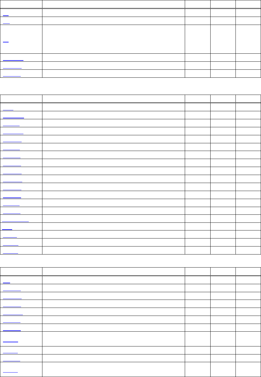
2.1.1 CT-S280
Print Control Commands
Commands Function MODE GS P Page
LF Printing and paper feed S・P 31
CR Back to printing S・P 32
FF
Printing in PAGE MODE and returning to STANDARD
MODE (at the selection of PAGE MODE) P 33
ESC FF Printing data in PAGE MODE P 34
ESC J Printing and feeding paper in minimum pitch S・P ○ 35
ESC d Printing and feeding the paper by “n” lines S・P 36
Print Character Commands
Command Function MODE GS P Page
CAN Canceling print data in PAGE MODE P 37
ESC SP Setting the right spacing of the character S・P ○ 38
ESC ! Collectively specifying the printing mode S・P 39
ESC % Specifying/Canceling download character set S・P 41
ESC & Defining the download characters S・P 42
ESC - Specifying/canceling underline S・P 44
ESC ? Deleting download characters S・P 45
ESC E Specifying/canceling emphasis printing S・P 46
ESC G Specifying/canceling double strike printing S・P 47
ESC M Selection of character fonts S・P 48
ESC R Selecting the international character set S・P 49
ESC V Specifying/canceling 90°-right-turned characters S 50
ESC t Selecting the character code table S・P 51
ESC { Specifying/canceling the inverted characters S 52
ESC ~ J Specifies/cancels printing in red (black-based paper) S・P 53
DC3 Specifies/cancels printing in red (black-based paper) S 55
GS ! Specifying the character size S・P 57
GS B Specifying/canceling the black/white inverted printing S・P 59
GS b Specifying/canceling the smoothing S・P 60
Print Position Commands
Command Function MODE GS P Page
HT Horizontal tab S・P 61
ESC $ Specifying the absolute positions S・P ○ 62
ESC D Setting horizontal tab position S・P 63
ESC T Selecting the character printing direction in PAGE MODE P 64
ESC W Defining the print area in PAGE MODE P ○ 65
ESC
\
Specifying the relative position S・P ○ 67
ESC a Aligning the characters S 68
GS $
Specifying the absolute vertical position of characters in
PAGE MODE P ○ 69
GS L Setting the left margin S ○ 70
GS W Setting the print area width S・P ○ 71
GS
\
Specifying the relative vertical position of a character in
PAGE MODE S・P ○ 73
- 11 -
Line Feed Span Commands
Command Function MODE GS P Page
ESC 2 Specifying initial line feed rate S・P 74
ESC 3 Setting line feed rate of minimum pitch S・P ○ 75
Bit Image Commands
Command Function MODE GS P Page
ESC * Specifying the bit image mode S・P 76
GS * Defining the download bit image S・P 77
GS / Printing the downloaded bit image S・P 78
GS v 0 Printing of raster bit image S 79
Status Commands
Command Function MODE GS P Page
DLE EOT Sending status in real-time S・P 81
ESC v Sending Printer status S・P 89
GS a Enabling/disabling ASB (Automatic Status Back) S・P 90
GS r Sending status S・P 93
Paper Detecting Commands
Command Function MODE GS P Page
ESC c 3
Selecting the Paper Sensor valid for Paper-end signal
output S・P 95
ESC c 4 Selecting the Paper Near-end Sensor valid for print stop S・P 96
Panel Switch Commands
Command Function MODE GS P Page
ESC c 5 Enabling/disabling the panel switches S・P 97
Macro Commands
Command Function MODE GS P Page
GS : Starting/ending macro definition S・P 98
GS ^ Executing the macro S・P 99
Bar Code Commands
Command Function MODE GS P Page
GS H Selecting of printing position of HRI characters S・P 103
GS f Selecting the font of HRI characters S・P 104
GS h Specifying the height of the bar code S・P 105
GS k Printing the bar code S・P 106
GS w Specifying the horizontal size (magnification) of bar code S・P 111
Commands for Non-volatile Memory
Command Function MODE GS P Page
FS p Printing the download NV bit images S 128
FS q Defining the download NV bit image S 130
- 12 -
Kanji Control Commands
Command Function MODE GS P Page
FS ! Collectively setting Kanji print mode S・P 132
FS & Setting Kanji mode S・P 133
FS - Setting/Canceling Kanji underline S・P 134
FS .
Canceling Kanji mode S・P 135
FS 2 Defining external character S・P 136
FS C Selecting Kanji code system S・P 138
FS S Setting Kanji space amount S・P ○ 140
FS W Setting/Canceling four times enlargement of Kanji S・P 141
FS ( A Setting font attribute of Kanji S・P 142
Printer Function Setting Commands
Command Function MODE GS P Page
GS ( E Printer function setting command S 153
GS ( K Selecting print control method S 200
GS ( M Customizing the printer S 204
GS ( N Designating font attribute S 207
Other Commands
Command Function MODE GS P Page
DLE ENQ Real-time request to printer S・P 219
DLE DC4 Buffer clear S・P 221
ESC =
Data input control S・P 222
ESC @ Initializing the printer S・P 223
ESC L Selecting PAGE MODE S 224
ESC S Selecting STANDARD MODE P 225
GS ( A Execution of test printing S 227
GS I Sending the printer ID S・P 228
GS P Specifying the basic calculation pitch S・P 235
In the Mode column: S = STANDARD MODE, P = PAGE MODE
O = shows the command affected by GS P.
- 13 -
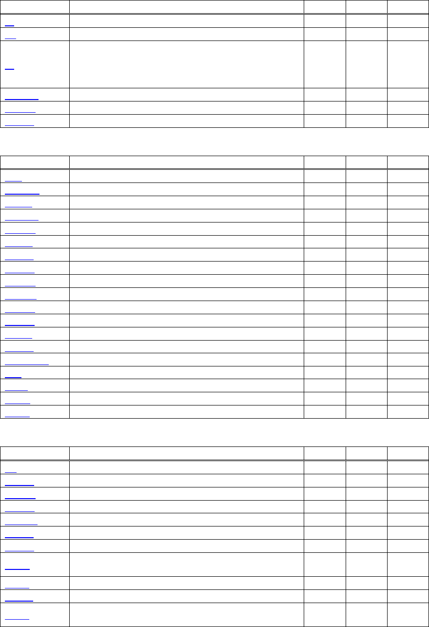
2.1.2 CT-S300/CT-S310
Print Contorl Commands
Command Function MODE GS P Page
LF Printing and paper feed S・P 31
CR Back to printing S・P 32
FF
(1)Printing in PAGE MODE and returning to STANDARD
MODE (at the selection of PAGE MODE)
(2)Printing of Black mark and paper feeding to the top of
the print position (with Black mark paper selected)
P 33
ESC FF Printing data in PAGE MODE P 34
ESC J Printing and feeding paper in minimum pitch S・P ○ 35
ESC d Printing and feeding the paper by “n” lines S・P 36
Print Character Commands
Command Function MODE GS P Page
CAN Canceling print data in PAGE MODE P 37
ESC SP Setting the right spacing of the character S・P ○ 38
ESC ! Collectively specifying the printing mode S・P 39
ESC % Specifying/Canceling download character set S・P 41
ESC & Defining the download characters S・P 42
ESC - Specifying/canceling underline S・P 44
ESC ? Deleting download characters S・P 45
ESC E Specifying/canceling emphasis printing S・P 46
ESC G Specifying/canceling double strike printing S・P 47
ESC M Selection of character fonts S・P 48
ESC R Selecting the international character set S・P 49
ESC V Specifying/canceling 90°-right-turned characters S 50
ESC t Selecting the character code table S・P 51
ESC { Specifying/canceling the inverted characters S 52
ESC ~ J Specifies/cancels printing in red (black-based paper) S・P 54
DC3 Specifies/cancels printing in red (black-based paper) S 56
GS ! Specifying the character size S・P 57
GS B Specifying/canceling the black/white inverted printing S・P 59
GS b Specifying/canceling the smoothing S・P 60
Print Position Commands
Command Function MODE GS P Page
HT Horizontal tab S・P 61
ESC $ Specifying the absolute positions S・P ○ 62
ESC D Setting horizontal tab position S・P 63
ESC T Selecting the character printing direction in PAGE MODE P 64
ESC W Defining the print area in PAGE MODE P ○ 65
ESC
\
Specifying the relative position S・P ○ 67
ESC a Aligning the characters S 68
GS $
Specifying the absolute vertical position of characters in
PAGE MODE P ○ 69
GS L Setting the left margin S ○ 70
GS W Setting the print area width S・P ○ 71
GS
\
Specifying the relative vertical position of a character in
PAGE MODE S・P ○ 73
- 14 -
Line Feed Span Commands
Command Function MODE GS P Page
ESC 2 Specifying initial line feed rate S・P 74
ESC 3 Setting line feed rate of minimum pitch S・P ○ 75
Bit Image Commands
Command Function MODE GS P Page
ESC * Specifying the bit image mode S・P 76
GS * Defining the download bit image S・P 77
GS / Printing the downloaded bit image S・P 78
GS v 0 Printing of raster bit image S 79
Status Commands
Command Function MODE GS P Page
DLE EOT Sending status in real-time S・P 81
GS a Enabling/disabling ASB (Automatic Status Back) S・P 90
GS r Sending status S・P 93
Paper Detecting Commands
Command Function MODE GS P Page
ESC c 3
Selecting the Paper Sensor valid for Paper-end signal
output S・P 95
ESC c 4 Selecting the Paper Near-end Sensor valid for print stop S・P 96
Panel Switch Commands
Command Function MODE GS P Page
ESC c 5 Enabling/disabling the panel switches S・P 97
Macro Commands
Command Function MODE GS P Page
GS : Starting/ending macro definition S・P 98
GS ^ Executing the macro S・P 99
Cutter Commands
Command Function MODE GS P Page
ESC i Full cut S・P 100
ESC m Partial cut S・P 101
GS V Cutting the paper S・P ○ 102
Bar Code Commands
Command Function MODE GS P Page
GS H Selecting of printing position of HRI characters S・P 103
GS f Selecting the font of HRI characters S・P 104
GS h Specifying the height of the bar code S・P 105
GS k Printing the bar code S・P 106
GS w Specifying the horizontal size (magnification) of bar code S・P 111
Commands for Non-volatile Memory
Command Function MODE GS P Page
FS p Printing the download NV bit images S 128
FS q Defining the download NV bit image S 130
- 15 -
Kanji Control Commands
Command Function MODE GS P Page
FS ! Collectively setting Kanji print mode S・P 132
FS & Setting Kanji mode S・P 133
FS - Setting/Canceling Kanji underline S・P 134
FS .
Canceling Kanji mode S・P 135
FS 2 Defining external character S・P 136
FS C Selecting Kanji code system S・P 138
FS S Setting Kanji space amount S・P ○ 140
FS W Setting/Canceling four times enlargement of Kanji S・P 141
FS ( A Setting font attribute of Kanji S・P 142
Black Mark Control Commands
Command Function MODE GS P Page
GS FF Printing and ejecting Black mark paper S・P 143
GS < Initializing the printer mechanism S・P 143
GS A Correcting the leader position of Black mark paper S・P 144
GS C 0 Setting the numbering print mode S・P 145
GS C 1 Setting the numbering counter mode (A) S・P 146
GS C 2 Setting the numbering counter S・P 147
GS C ; Setting the numbering counter mode (B) S・P 148
GS c Print the counter S・P 149
Printer Function Setting Commands
Command Function MODE GS P Page
GS ( D Enabling or disabling real-time command S 152
GS ( E Printer function setting command S 153
GS ( K Selecting print control method S 200
GS ( M Customizing the printer S 204
GS ( N Designating font attribute S 207
Other Commands
Command Function MODE GS P Page
DLE ENQ Real-time request to printer S・P 219
DLE DC4
Outputting specified pulse in real-time/Buffer clear S・P 220/221
ESC =
Data input control S・P 222
ESC @ Initializing the printer S・P 223
ESC L Selecting PAGE MODE S 224
ESC S Selecting STANDARD MODE P 225
ESC p Generating the specified pulses S・P 226
GS ( A Execution of test printing S 227
GS I Sending the printer ID S・P 228
GS P Specifying the basic calculation pitch S・P 235
ESC RS Sound buzzer S・P 236
In the Mode column: S = STANDARD MODE, P = PAGE MODE
O = shows the command affected by GS P.
- 16 -
2.1.3 CT-S2000
Print Contorl Commands
Command Function MODE GS P Page
LF Printing and paper feed S・P 31
CR Back to printing S・P 32
FF
(1)Printing in PAGE MODE and returning to STANDARD
MODE (at the selection of PAGE MODE)
(2)Printing of Black mark and paper feeding to the top of
the print position (with Black mark paper selected)
P 33
ESC FF Printing data in PAGE MODE P 34
ESC J Printing and feeding paper in minimum pitch S・P ○ 35
ESC d Printing and feeding the paper by “n” lines S・P 36
Print Character Commands
Command Function MODE GS P Page
CAN Canceling print data in PAGE MODE P 37
ESC SP Setting the right spacing of the character S・P ○ 38
ESC ! Collectively specifying the printing mode S・P 39
ESC % Specifying/Canceling download character set S・P 41
ESC & Defining the download characters S・P 42
ESC - Specifying/canceling underline S・P 44
ESC ? Deleting download characters S・P 45
ESC E Specifying/canceling emphasis printing S・P 46
ESC G Specifying/canceling double strike printing S・P 47
ESC M Selection of character fonts S・P 48
ESC R Selecting the international character set S・P 49
ESC V Specifying/canceling 90°-right-turned characters S 50
ESC t Selecting the character code table S・P 51
ESC { Specifying/canceling the inverted characters S 52
ESC ~ J Specifies/cancels printing in red (black-based paper) S・P 54
DC3 Specifies/cancels printing in red (black-based paper) S 56
GS ! Specifying the character size S・P 57
GS B Specifying/canceling the black/white inverted printing S・P 59
GS b Specifying/canceling the smoothing S・P 60
Print Position Commands
Command Function MODE GS P Page
HT Horizontal tab S・P 61
ESC $ Specifying the absolute positions S・P ○ 62
ESC D Setting horizontal tab position S・P 63
ESC T Selecting the character printing direction in PAGE MODE P 64
ESC W Defining the print area in PAGE MODE P ○ 65
ESC
\
Specifying the relative position S・P ○ 67
ESC a Aligning the characters S 68
GS $
Specifying the absolute vertical position of characters in
PAGE MODE P ○ 69
GS L Setting the left margin S ○ 70
GS W Setting the print area width S・P ○ 71
GS
\
Specifying the relative vertical position of a character in
PAGE MODE S・P ○ 73
- 17 -
Line Feed Span Commands
Command Function MODE GS P Page
ESC 2 Specifying initial line feed rate S・P 74
ESC 3 Setting line feed rate of minimum pitch S・P ○ 75
Bit Image Commands
Command Function MODE GS P Page
ESC * Specifying the bit image mode S・P 76
GS * Defining the download bit image S・P 77
GS / Printing the downloaded bit image S・P 78
GS v 0 Printing of raster bit image S 79
Status Commands
Command Function MODE GS P Page
DLE EOT Sending status in real-time S・P 81
ESC u
Transmitting the status of peripheral equipment
(Serial Mode Only) S・P 88
ESC v Sending Printer status S・P 89
GS a Enabling/disabling ASB (Automatic Status Back) S・P 90
GS r Sending status S・P 93
Paper Detecting Commands
Command Function MODE GS P Page
ESC c 3
Selecting the Paper Sensor valid for Paper-end signal
output S・P 95
ESC c 4 Selecting the Paper Near-end Sensor valid for print stop S・P 96
Panel Switch Commands
Command Function MODE GS P Page
ESC c 5 Enabling/disabling the panel switches S・P 97
Macro Commands
Command Function MODE GS P Page
GS : Starting/ending macro definition S・P 98
GS ^ Executing the macro S・P 99
Cutter Commands
Command Function MODE GS P Page
ESC i Full cut S・P 100
ESC m Partial cut S・P 101
GS V Cutting the paper S・P ○ 102
Bar Code Commands
Command Function MODE GS P Page
GS H Selecting of printing position of HRI characters S・P 103
GS f Selecting the font of HRI characters S・P 104
GS h Specifying the height of the bar code S・P 105
GS k Printing the bar code S・P 106
GS w Specifying the horizontal size (magnification) of bar code S・P 111
- 18 -
Commands for Non-volatile Memory
Command Function MODE GS P Page
GS ( C Editing user NV memory S 112
GS ( L
GS 8 L
Specifying graphics data S 118
GS g 0 Initializing maintenance counter S 126
GS g 2 Sending maintenance counter S 127
FS p Printing the download NV bit images S 128
FS q Defining the download NV bit image S 130
Kanji Control Commands
Command Function MODE GS P Page
FS ! Collectively setting Kanji print mode S・P 132
FS & Setting Kanji mode S・P 133
FS - Setting/Canceling Kanji underline S・P 134
FS .
Canceling Kanji mode S・P 135
FS 2 Defining external character S・P 136
FS C Selecting Kanji code system S・P 138
FS S Setting Kanji space amount S・P ○ 140
FS W Setting/Canceling four times enlargement of Kanji S・P 141
FS ( A Setting font attribute of Kanji S・P 142
Black Mark Control Commands
Command Function MODE GS P Page
GS FF
Printing and ejecting Black mark paper S・P 143
GS <
Initializing the printer mechanism S・P 143
GS A
Correcting the leader position of Black mark paper S・P 144
GS C 0
Setting the numbering print mode S・P 145
GS C 1
Setting the numbering counter mode (A) S・P 146
GS C 2
Setting the numbering counter S・P 147
GS C ;
Setting the numbering counter mode (B) S・P 148
GS c Print the counter S・P 149
GS l
Setting the Black mark length S・P 150
Printer Function Setting Commands
Command Function MODE GS P Page
GS ( D Enabling or disabling real-time command S 152
GS ( E Printer function setting command S 153
GS ( K Selecting print control method S 200
GS ( M Customizing the printer S 204
GS ( N Designating font attribute S 207
2-dimensional Code Commands
Command Function MODE GS P Page
GS ( k Setting and printing 2-dimensional code S・P 208

- 19 -
Other Commands
Command Function MODE GS P Page
DLE ENQ Real-time request to printer S・P 219
DLE DC4
Outputting specified pulse in real-time/Buffer clear S・P 220/221
ESC =
Data input control S・P 222
ESC @ Initializing the printer S・P 223
ESC L Selecting PAGE MODE S 224
ESC S Selecting STANDARD MODE P 225
ESC p Generating the specified pulses S・P 226
GS ( A Execution of test printing S 227
GS I Sending the printer ID S・P 228
GS P Specifying the basic calculation pitch S・P 235
ESC RS Sound buzzer S・P 236
In the Mode column: S = STANDARD MODE, P = PAGE MODE
O = shows the command affected by GS P.

- 20 -
2.1.4 CT-S4000
Print Contorl Commands
Command Function MODE GS P Page
LF Printing and paper feed S・P 31
CR Back to printing S・P 32
FF
(1)Printing in PAGE MODE and returning to STANDARD
MODE (at the selection of PAGE MODE)
(2)Printing of Black mark and paper feeding to the top of
the print position (with Black mark paper selected)
P 33
ESC FF Printing data in PAGE MODE P 34
ESC J Printing and feeding paper in minimum pitch S・P ○ 35
ESC d Printing and feeding the paper by “n” lines S・P 36
Print Character Commands
Command Function MODE GS P Page
CAN Canceling print data in PAGE MODE P 37
ESC SP Setting the right spacing of the character S・P ○ 38
ESC ! Collectively specifying the printing mode S・P 39
ESC % Specifying/Canceling download character set S・P 41
ESC & Defining the download characters S・P 42
ESC - Specifying/canceling underline S・P 44
ESC ? Deleting download characters S・P 45
ESC E Specifying/canceling emphasis printing S・P 46
ESC G Specifying/canceling double strike printing S・P 47
ESC M Selection of character fonts S・P 48
ESC R Selecting the international character set S・P 49
ESC V Specifying/canceling 90°-right-turned characters S 50
ESC t Selecting the character code table S・P 51
ESC { Specifying/canceling the inverted characters S 52
ESC ~ J Specifies/cancels printing in red (black-based paper) S・P 54
DC3 Specifies/cancels printing in red (black-based paper) S 56
GS ! Specifying the character size S・P 57
GS B Specifying/canceling the black/white inverted printing S・P 59
GS b Specifying/canceling the smoothing S・P 60
Print Position Commands
Command Function MODE GS P Page
HT Horizontal tab S・P 61
ESC $ Specifying the absolute positions S・P ○ 62
ESC D Setting horizontal tab position S・P 63
ESC T Selecting the character printing direction in PAGE MODE P 64
ESC W Defining the print area in PAGE MODE P ○ 65
ESC
\
Specifying the relative position S・P ○ 67
ESC a Aligning the characters S 68
GS $
Specifying the absolute vertical position of characters in
PAGE MODE P ○ 69
GS L Setting the left margin S ○ 70
GS W Setting the print area width S・P ○ 71
GS
\
Specifying the relative vertical position of a character in
PAGE MODE S・P ○ 73
- 21 -
Line Feed Span Commands
Command Function MODE GS P Page
ESC 2 Specifying initial line feed rate S・P 74
ESC 3 Setting line feed rate of minimum pitch S・P ○ 75
Bit Image Commands
Command Function MODE GS P Page
ESC * Specifying the bit image mode S・P 76
GS * Defining the download bit image S・P 77
GS / Printing the downloaded bit image S・P 78
GS v 0 Printing of raster bit image S 79
Status Commands
Command Function MODE GS P Page
DLE EOT Sending status in real-time S・P 81
ESC u
Transmitting the status of peripheral equipment
(Serial Mode Only) S・P 88
ESC v Sending Printer status S・P 89
GS a Enabling/disabling ASB (Automatic Status Back) S・P 90
GS r Sending status S・P 93
Paper Detecting Commands
Command Function MODE GS P Page
ESC c 3
Selecting the Paper Sensor valid for Paper-end signal
output S・P 95
ESC c 4 Selecting the Paper Near-end Sensor valid for print stop S・P 96
Panel Switch Commands
Command Function MODE GS P Page
ESC c 5 Enabling/disabling the panel switches S・P 97
Macro Commands
Command Function MODE GS P Page
GS : Starting/ending macro definition S・P 98
GS ^ Executing the macro S・P 99
Cutter Commands
Command Function MODE GS P Page
ESC i Full cut S・P 100
ESC m Partial cut S・P 101
GS V Cutting the paper S・P ○ 102
Bar Code Commands
Command Function MODE GS P Page
GS H Selecting of printing position of HRI characters S・P 103
GS f Selecting the font of HRI characters S・P 104
GS h Specifying the height of the bar code S・P 105
GS k Printing the bar code S・P 106
GS w Specifying the horizontal size (magnification) of bar code S・P 111
- 22 -
Commands for Non-volatile Memory
Command Function MODE GS P Page
GS ( C Editing user NV memory S 112
GS ( L
GS 8 L
Specifying graphics data S 118
GS g 0 Initializing maintenance counter S 126
GS g 2 Sending maintenance counter S 127
FS p Printing the download NV bit images S 128
FS q Defining the download NV bit image S 130
Kanji Control Commands
Command Function MODE GS P Page
FS ! Collectively setting Kanji print mode S・P 132
FS & Setting Kanji mode S・P 133
FS - Setting/Canceling Kanji underline S・P 134
FS .
Canceling Kanji mode S・P 135
FS 2 Defining external character S・P 136
FS C Selecting Kanji code system S・P 138
FS S Setting Kanji space amount S・P ○ 140
FS W Setting/Canceling four times enlargement of Kanji S・P 141
FS ( A Setting font attribute of Kanji S・P 142
Black Mark Control Commands
Command Function MODE GS P Page
GS FF Printing and ejecting Black mark paper S・P 143
GS < Initializing the printer mechanism S・P 143
GS A Correcting the leader position of Black mark paper S・P 144
GS C 0 Setting the numbering print mode S・P 145
GS C 1 Setting the numbering counter mode (A) S・P 146
GS C 2 Setting the numbering counter S・P 147
GS C ; Setting the numbering counter mode (B) S・P 148
GS c Print the counter S・P 149
GS l Setting the Black mark length S・P 150
GS p Changing the paper type S・P 151
Printer Function Setting Commands
Command Function MODE GS P Page
GS ( D Enabling or disabling real-time command S 152
GS ( E Printer function setting command S 153
GS ( K Selecting print control method S 200
GS ( M Customizing the printer S 204
GS ( N Designating font attribute S 207
2-dimensional Code Commands
Command Function MODE GS P Page
GS ( k Setting and printing 2-dimensional code S・P 208

- 23 -
Other Commands
Command Function MODE GS P Page
DLE ENQ Real-time request to printer S・P 219
DLE DC4
Outputting specified pulse in real-time/Buffer clear S・P 220/221
ESC =
Data input control S・P 222
ESC @ Initializing the printer S・P 223
ESC L Selecting PAGE MODE S 224
ESC S Selecting STANDARD MODE P 225
ESC p Generating the specified pulses S・P 226
GS ( A Execution of test printing S 227
GS I Sending the printer ID S・P 228
GS P Specifying the basic calculation pitch S・P 235
ESC RS Sound buzzer S・P 236
In the Mode column: S = STANDARD MODE, P = PAGE MODE
O = shows the command affected by GS P.
- 24 -
2.1.5 BD2-2220
Print Contorl Commands
Command Function MODE GS P Page
LF Printing and paper feed S・P 31
CR Back to printing S・P 32
FF
Printing in PAGE MODE and returning to STANDARD
MODE (at the selection of PAGE MODE) P 33
ESC FF Printing data in PAGE MODE P 34
ESC J Printing and feeding paper in minimum pitch S・P ○ 35
ESC d Printing and feeding the paper by “n” lines S・P 36
Print Character Commands
Command Function MODE GS P Page
CAN Canceling print data in PAGE MODE P 37
ESC SP Setting the right spacing of the character S・P ○ 38
ESC ! Collectively specifying the printing mode S・P 39
ESC % Specifying/Canceling download character set S・P 41
ESC & Defining the download characters S・P 42
ESC - Specifying/canceling underline S・P 44
ESC ? Deleting download characters S・P 45
ESC E Specifying/canceling emphasis printing S・P 46
ESC G Specifying/canceling double strike printing S・P 47
ESC M Selection of character fonts S・P 48
ESC R Selecting the international character set S・P 49
ESC V Specifying/canceling 90°-right-turned characters S 50
ESC t Selecting the character code table S・P 51
ESC { Specifying/canceling the inverted characters S 52
GS ! Specifying the character size S・P 57
GS B Specifying/canceling the black/white inverted printing S・P 59
GS b Specifying/canceling the smoothing S・P 60
Print Position Commands
Command Function MODE GS P Page
HT Horizontal tab S・P 61
ESC $ Specifying the absolute positions S・P ○ 62
ESC D Setting horizontal tab position S・P 63
ESC T Selecting the character printing direction in PAGE MODE P 64
ESC W Defining the print area in PAGE MODE P ○ 65
ESC
\
Specifying the relative position S・P ○ 67
ESC a Aligning the characters S 68
GS $
Specifying the absolute vertical position of characters in
PAGE MODE P ○ 69
GS L Setting the left margin S ○ 70
GS W Setting the print area width S・P ○ 71
GS
\
Specifying the relative vertical position of a character in
PAGE MODE S・P ○ 73
Line Feed Span Commands
Command Function MODE GS P Page
ESC 2 Specifying initial line feed rate S・P 74
ESC 3 Setting line feed rate of minimum pitch S・P ○ 75

- 25 -
Bit Image Commands
Command Function MODE GS P Page
ESC * Specifying the bit image mode S・P 76
GS * Defining the download bit image S・P 77
GS / Printing the downloaded bit image S・P 78
GS v 0 Printing of raster bit image S 79
Status Commands
Command Function MODE GS P Page
DLE EOT Sending status in real-time S・P 81
GS a Enabling/disabling ASB (Automatic Status Back) S・P 90
GS r Sending status S・P 93
Paper Detecting Commands
Command Function MODE GS P Page
ESC c 3
Selecting the Paper Sensor valid for Paper-end signal
output S・P 95
ESC c 4 Selecting the Paper Near-end Sensor valid for print stop S・P 96
Panel Switch Commands
Command Function MODE GS P Page
ESC c 5 Enabling/disabling the panel switches S・P 97
Macro Commands
Command Function MODE GS P Page
GS : Starting/ending macro definition S・P 98
GS ^ Executing the macro S・P 99
Cutter Commands
Command Function MODE GS P Page
ESC i Full cut S・P 100
ESC m Partial cut S・P 101
GS V Cutting the paper S・P ○ 102
Bar Code Commands
Command Function MODE GS P Page
GS H Selecting of printing position of HRI characters S・P 103
GS f Selecting the font of HRI characters S・P 104
GS h Specifying the height of the bar code S・P 105
GS k Printing the bar code S・P 106
GS w Specifying the horizontal size (magnification) of bar code S・P 111
Commands for Non-volatile Memory
Command Function MODE GS P Page
FS p Printing the download NV bit images S 128
FS q Defining the download NV bit image S 130

- 26 -
Kanji Control Commands
Command Function MODE GS P Page
FS ! Collectively setting Kanji print mode S・P 132
FS & Setting Kanji mode S・P 133
FS - Setting/Canceling Kanji underline S・P 134
FS .
Canceling Kanji mode S・P 135
FS 2 Defining external character S・P 136
FS C Selecting Kanji code system S・P 138
FS S Setting Kanji space amount S・P ○ 140
FS W Setting/Canceling four times enlargement of Kanji S・P 141
FS ( A Setting font attribute of Kanji S・P 142
Printer Function Setting Commands
Command Function MODE GS P Page
GS ( E Printer function setting command S 153
GS ( K Selecting print control method S 200
GS ( M Customizing the printer S 204
Other Commands
Command Function MODE GS P Page
DLE ENQ Real-time request to printer S・P 219
DLE DC4 Buffer clear S・P 221
ESC =
Data input control S・P 222
ESC @ Initializing the printer S・P 223
ESC L Selecting PAGE MODE S 224
ESC S Selecting STANDARD MODE P 225
GS ( A Execution of test printing S 227
GS I Sending the printer ID S・P 228
GS P Specifying the basic calculation pitch S・P 235
In the Mode column: S = STANDARD MODE, P = PAGE MODE
O = shows the command affected by GS P.
- 27 -
2.1.6 PMU2XXX
Print Contorl Commands
Command Function MODE GS P Page
LF Printing and paper feed S・P 31
CR Back to printing S・P 32
FF
(1)Printing in PAGE MODE and returning to STANDARD
MODE (at the selection of PAGE MODE)
(2)Printing of Black mark and paper feeding to the top of
the print position (with Black mark paper selected)
P 33
ESC FF Printing data in PAGE MODE P 34
ESC J Printing and feeding paper in minimum pitch S・P ○ 35
ESC d Printing and feeding the paper by “n” lines S・P 36
Print Character Commands
Command Function MODE GS P Page
CAN Canceling print data in PAGE MODE P 37
ESC SP Setting the right spacing of the character S・P ○ 38
ESC ! Collectively specifying the printing mode S・P 39
ESC % Specifying/Canceling download character set S・P 41
ESC & Defining the download characters S・P 42
ESC - Specifying/canceling underline S・P 44
ESC ? Deleting download characters S・P 45
ESC E Specifying/canceling emphasis printing S・P 46
ESC G Specifying/canceling double strike printing S・P 47
ESC M Selection of character fonts S・P 48
ESC R Selecting the international character set S・P 49
ESC V Specifying/canceling 90°-right-turned characters S 50
ESC t Selecting the character code table S・P 51
ESC { Specifying/canceling the inverted characters S 52
GS ! Specifying the character size S・P 57
GS B Specifying/canceling the black/white inverted printing S・P 59
GS b Specifying/canceling the smoothing S・P 60
Print Position Commands
Command Function MODE GS P Page
HT Horizontal tab S・P 61
ESC $ Specifying the absolute positions S・P ○ 62
ESC D Setting horizontal tab position S・P 63
ESC T Selecting the character printing direction in PAGE MODE P 64
ESC W Defining the print area in PAGE MODE P ○ 65
ESC
\
Specifying the relative position S・P ○ 67
ESC a Aligning the characters S 68
GS $
Specifying the absolute vertical position of characters in
PAGE MODE P ○ 69
GS L Setting the left margin S ○ 70
GS W Setting the print area width S・P ○ 71
GS
\
Specifying the relative vertical position of a character in
PAGE MODE S・P ○ 73
Line Feed Span Commands
Command Function MODE GS P Page
ESC 2 Specifying initial line feed rate S・P 74
ESC 3 Setting line feed rate of minimum pitch S・P ○ 75
- 28 -
Bit Image Commands
Command Function MODE GS P Page
ESC * Specifying the bit image mode S・P 76
GS * Defining the download bit image S・P 77
GS / Printing the downloaded bit image S・P 78
GS v 0 Printing of raster bit image S 79
Status Commands
Command Function MODE GS P Page
DLE EOT Sending status in real-time S・P 81
GS a Enabling/disabling ASB (Automatic Status Back) S・P 90
GS r Sending status S・P 93
Paper Detecting Commands
Command Function MODE GS P Page
ESC c 3
Selecting the Paper Sensor valid for Paper-end signal
output S・P 95
ESC c 4 Selecting the Paper Near-end Sensor valid for print stop S・P 96
Panel Switch Commands
Command Function MODE GS P Page
ESC c 5 Enabling/disabling the panel switches S・P 97
Macro Commands
Command Function MODE GS P Page
GS : Starting/ending macro definition S・P 98
GS ^ Executing the macro S・P 99
Cutter Commands
Command Function MODE GS P Page
ESC i Full cut S・P 100
ESC m Partial cut S・P 101
GS V Cutting the paper S・P ○ 102
Bar Code Commands
Command Function MODE GS P Page
GS H Selecting of printing position of HRI characters S・P 103
GS f Selecting the font of HRI characters S・P 104
GS h Specifying the height of the bar code S・P 105
GS k Printing the bar code S・P 106
GS w Specifying the horizontal size (magnification) of bar code S・P 111
Commands for Non-volatile Memory
Command Function MODE GS P Page
FS p Printing the download NV bit images S 128
FS q Defining the download NV bit image S 130

- 29 -
Kanji Control Commands
Command Function MODE GS P Page
FS ! Collectively setting Kanji print mode S・P 132
FS & Setting Kanji mode S・P 133
FS - Setting/Canceling Kanji underline S・P 134
FS .
Canceling Kanji mode S・P 135
FS 2 Defining external character S・P 136
FS C Selecting Kanji code system S・P 138
FS S Setting Kanji space amount S・P ○ 140
FS W Setting/Canceling four times enlargement of Kanji S・P 141
FS ( A Setting font attribute of Kanji S・P 142
Black Mark Control Commands
Command Function MODE GS P Page
GS FF Printing and ejecting Black mark paper S・P 143
Printer Function Setting Commands
Command Function MODE GS P Page
GS ( E Printer function setting command S 153
GS ( K Selecting print control method S 200
GS ( M Customizing the printer S 204
Other Commands
Command Function MODE GS P Page
DLE ENQ Real-time request to printer S・P 219
DLE DC4 Buffer clear S・P 221
ESC =
Data input control S・P 222
ESC @ Initializing the printer S・P 223
ESC L Selecting PAGE MODE S 224
ESC S Selecting STANDARD MODE P 225
GS ( A Execution of test printing S 227
GS I Sending the printer ID S・P 228
GS P Specifying the basic calculation pitch S・P 235
In the Mode column: S = STANDARD MODE, P = PAGE MODE
O = shows the command affected by GS P.

- 30 -
2.2 Command Details
2.2.1 Description of Items
XXXX
support model
[Function] The name of a command.
[Code] The string of codes comprising the command is represented by < >H for hexadecimal numbers, < >B
for binary numbers, and < > for decimal numbers, [ ] k denotes the number of repetition of “k” times.
[Range] Indicates the values (setting range) of arguments of the command.
Note: If values outside the defined domain specified with control codes are used, malfunctions
could possibly occur, so be sure to use the values within the defined domain.
*The defined domain may differ depending on the model or printer setting.
[Outline] [The specification which is common to the model]
Indicates command functions common to relevant models.
[The specification which depend on the model]
Indicates the command function dependent on the model.
[Caution] Describes important points and cautionary notes, as required.
[Default] Initial values for the command if it has arguments.
[See Also] Describes commands related to the command when it is used.
[Sample Program]
Describes examples of coding on Quick-Basic.
* Examples are only for reference. They may vary depending on language and version. For details, please refer
to a manual in your language.
[Print Results]
Describes the print results obtained by executing the above programs. However, the print results shown are
different in scale from actual print results
- 31 -
2.2.2 Print Control Commands
LF
CT-S280 CT-S300 CT-S2000 CT-S4000 BD2-2220 CT-S310
support model PMU2XXX
[Function] Printing and paper feed
[Code] <0A>H
[Outline] [The specification which is common to the model]
Prints data inside the print buffer and feeds paper based on the line feed amount having been set.
[Caution] After this command is executed, the beginning of the line is taken as the start position for the next
point.
[See Also] ESC 2、ESC 3
[Sample Program] [Print Results]
AAA
BBB
CCC
Print and line feed
Print and line feed
Line feed only
Print and line feed
LPRINT "AAA"; CHR$(&HA);
LPRINT "BBB"; CHR$(&HA); CHR$(&HA);
LPRINT "CCC"; CHR$(&HA);
- 32 -
CR
CT-S280 CT-S300 CT-S2000 CT-S4000 BD2-2220 CT-S310
support model PMU2XXX
[Function] Back to printing
[Code] <0D>H
[Outline] [The specification which is common to the model]
(1) When memory switch 1-5 is OFF:
This command is ignored.
(2) When memory switch 1-5 is ON:
The same operation as LF is executed.
[See Also] LF
[Sample Program] [Print Results]
In case of (2)
LPRINT "AAA"; CHR$(&HD); AAA
BBB
CCC
Print and line feed
Print and line feed
Line feed onl
y
Print and line feed
LPRINT "BBB"; CHR$(&HD);
LPRINT CHR$(&HD);
LPRINT "CCC"; CHR$(&HD);
- 33 -
FF (At selection of PAGE MODE)
CT-S280 CT-S300 CT-S2000 CT-S4000 BD2-2220 CT-S310
support model PMU2XXX
[Function] Printing in PAGE MODE and returning to STANDARD MODE (at the selection of PAGE MODE)
[Code] <0C>H
[Outline] [The specification which is common to the model]
Executes a batch printout of the data mapped in the entire print area, and then returns to
STANDARD MODE.
[Caution] • All mapped data is erased after printout.
• The print area set up by ESC W is initialized.
• This command does not execute a paper cut.
• After this command is executed, the beginning of the line is taken as the start position for the next
print.
• This command is only effective when the PAGE MODE is selected.
CT-S4000
• When selecting BM paper or label paper to specify the PAGE MODE, data extended to all
printing area is printed in batch. After returning to the STANDARD MODE, setting the
start position of next label is carried out.
[See Also] Appendix 5.1.4 “Example of Using PAGE MODE”
ESC FF、ESC L、ESC S
FF (valid only for Black mark specification)
CT-S280 CT-S300 CT-S2000 CT-S4000 BD2-2220 CT-S310
support model PMU2XXX
[Function] At selection of Black mark paper (valid only for Black mark specification)
[Outline] [The specification which is common to the model]
This command prints the data in the printer buffer and searches for the head of the next Black mark
(Black mark position)
[Caution] • This command does not execute a paper cut.
• After this command is executed, the beginning of the line is taken as the start position for the next
print.
• Valid only for label- or BM-supported model.
(Please confirm specifications for the details.)
[See Also] GS FF
- 34 -
ESC FF
CT-S280 CT-S300 CT-S2000 CT-S4000 BD2-2220 CT-S310
support model PMU2XXX
[Function] Printing data in PAGE MODE
[Code] <1B>H<0C>H
[Outline] [The specification which is common to the model]
Executes a batch printout of the data mapped in the entire print area in PAGE MODE.
[Caution] • This command is only effective when PAGE MODE is selected.
• Mapped data, as well as the ESC T and ESC W settings, and the character mapping position are
held even after printing.
[See Also] Appendix 5.1 “Explanation on PAGE MODE”
FF、ESC L、ESC S

- 35 -
ESC J n
CT-S280 CT-S300 CT-S2000 CT-S4000 BD2-2220 CT-S310
support model PMU2XXX
[Function] Printing and feeding paper in minimum pitch
[Code] <1B>H<4A>H<n>
[Range] 0≦n≦255
[Outline] [The specification which is common to the model]
Prints the data held in the print buffer and feeds paper by [n×basic calculation pitch] inches.
[Caution] • After this command is executed, the beginning of the line is taken as the start position for the next
print.
• The line feed width can be set separately for the STANDARD and PAGE MODES.
• This command does not affect the line feed width defined by ESC 2 or ESC 3.
• The basic calculation pitch is set by GS P.
• Fractions resulting from calculation are corrected with the minimum pitch of the mechanism, and
the remainder is omitted.
• In STANDARD MODE, this command uses the vertical (paper feed direction) basic calculation pitch
(y).
• In PAGE MODE, this command acts differently depending on the start point:
(1) If the start point specified by ESC T is top left or bottom right, the command uses the vertical
(Paper feed direction) basic calculation pitch (y).
(2) If the start point specified by ESC T is top right or bottom left, the command uses the
horizontal (Perpendicular to the paper feed direction) basic calculation pitch (x).
• The maximum settable line feed width is 1016 mm (40 inches). A setting greater than this
maximum is trimmed to the maximum.
[Default] The initial value is not defined.
[Sample Program]
Refer to Sample Program and Print Results for ESC 2.

- 36 -
ESC d n
CT-S280 CT-S300 CT-S2000 CT-S4000 BD2-2220 CT-S310
support model PMU2XXX
[Function] Printing and feeding the paper by “n” lines
[Code] <1B>H<64>H<n>
[Range] 0≦n≦255
[Outline] [The specification which is common to the model]
Prints data in the print buffer and feeds paper by “n” lines. Specified lines do not remain.
[Caution] • After this command is executed, the beginning of the line is taken as the start position for the next
print.
• If [n×line feed width] exceeds approximately 1016 mm, this command feeds paper by
approximately 1016 mm (40 inches).
[Default] The initial value is not defined.
[Sample Program] [Print Results]
LPRINT "AAAAA";
2
/
6-inch line feed
AAAAA
AAAAA
LPRINT CHR$(&H1B);"d";CHR$(2);
LPRINT "AAAAA";CHR$(&HA);
- 37 -
2.2.3 Print Character Commands
CAN
CT-S280 CT-S300 CT-S2000 CT-S4000 BD2-2220 CT-S310
support model PMU2XXX
[Function] Canceling print data in PAGE MODE
[Code] <18>H
[Outline] [The specification which is common to the model]
Erases all data contained in the currently effective print area in PAGE MODE.
[Caution] • This command is only effective when PAGE MODE is selected.
• If the previously established print area overlaps the currently effective print area, the overlapped
data in the previously established area will be erased.
[See Also] Appendix 5.1 “Explanation on PAGE MODE”
ESC L、ESC W

- 38 -
ESC SP n
CT-S280 CT-S300 CT-S2000 CT-S4000 BD2-2220 CT-S310
support model PMU2XXX
[Function] Setting the right spacing of the character
[Code] <1B>H<20>H<n>
[Range] 0≦n≦255
[Outline] [The specification which is common to the model]
Sets the right spacing of character to [n×basic calculation pitch] inches.
[Caution] • If the horizontal magnification of character is 2 or more, the right spacing increases with the
magnification.
• Does not affect Kanji.
• The right spacing can be set separately for the STANDARD and PAGE MODES.
• The basic calculation pitch is set by GS P. Once defined, the right spacing is not changed if the
basic calculation pitch is changed by GS P.
• Fractions resulting from calculation are corrected with the minimum pitch of the mechanism, and
the remainder is omitted.
• In STANDARD MODE, this command uses the horizontal basic calculation pitch (x).
• In PAGE MODE, the basic calculation pitch used by this command depends on the start point:
(1) If the start point specified by ESC T is top left or bottom right, the command uses the
horizontal basic calculation pitch (x).
(2) If the start point specified by ESC T is top right or bottom left, the command uses the vertical
basic calculation pitch (y).
• The maximum right spacing is capable of approximately 31.906 mm (255/203 inches). A setting
greater than this maximum is trimmed to the maximum.
[Default] n=0
[See Also] GS P
[Sample Program] [Print Results]
LPRINT CHR$(&H1B);" "; CHR$(0);
LPRINT "AAAAA"; CHR$(&HA); AAAAA
A A A A A
A A A A A
0-dot s
p
ac
e
1-dot s
p
ac
e
12-dots space
LPRINT CHR$(&H1B);" "; CHR$(1);
LPRINT "AAAAA"; CHR$(&HA);
LPRINT CHR$(&H1B);" "; CHR$(12);
LPRINT "AAAAA"; CHR$(&HA);
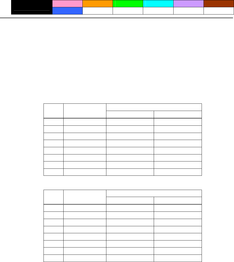
- 39 -
ESC ! n
CT-S280 CT-S300 CT-S2000 CT-S4000 BD2-2220 CT-S310
support model PMU2XXX
[Function] Collectively specifying the printing mode
[Code] <1B>H<21>H<n>
[Range] 0≦n≦255
[Outline] [The specification which is common to the model]
Printing mode is assigned.
[The specification which depend on the model]
CT-S300/CT-S310
Value
Bit Function 0 1
0 Character Font Font A (12 x 24) Font B (9 x 17)
1 Undefined — —
2 Undefined — —
3 Emphasis Canceled Specified
4 Double height Canceled Specified
5 Double width Canceled Specified
6 Undefined — —
7 Underline Canceled Specified
CT-S280/CT-S2000/CT-S4000/BD2-2220/PMU2XXX
Value
Bit Function 0 1
0 Character Font Font A (12 x 24) Font B (9 x 24)
1 Undefined — —
2 Undefined — —
3 Emphasis Canceled Specified
4 Double height Canceled Specified
5 Double width Canceled Specified
6 Undefined — —
7 Underline Canceled Specified
- 40 -
[Caution] • With double height and double width being specified simultaneously, quadruple characters are
created.
• An underline is attached to the full character width, which, however, is not attached to the part
having been skipped by the horizontal tab (HT). Neither is it attached to 90°-right-turned
characters.
• The underline width is as specified by the ESC – command. (The default setting is 1 dot width.)
• Setting by this command is invalid for Kanji except setting and canceling of enhanced printing.
• In case characters with different vertical magnification ratios coexist on the same line, they are
printed on the same base line.
• ESC E, ESC M, ESC –, and GS ! can individually set or cancel the mode but the command
processed last is valid.
• Setting or canceling of enhanced 3rd bit is valid for alphanumeric and kana and kanji. Other print
mode is valid only for alphanumeric and kana characters.
[Default] n=0
[See Also] ESC E、ESC -、GS !
[Sample Program] [Print Results]
LPRINT CHR$(&H1B);"!"; CHR$(&H00);"H";
LPRINT CHR$(&H1B);"!"; CHR$(&H01);"H";
Font B + Emphasis
+ Quadruple + Underline
LPRINT CHR$(&H1B);"!"; CHR$(&H08);"H";
LPRINT CHR$(&H1B);"!"; CHR$(&H10);"H";
LPRINT CHR$(&H1B);"!"; CHR$(&H20);"H"; Font A + Underline
Font A + Double width
LPRINT CHR$(&H1B);"!"; CHR$(&H80);"H";
LPRINT CHR$(&H1B);"!"; CHR$(&HB9);"H"; Font A + Double height
LPRINT CHR$(&HA); Font A + Emphasis
Font A
Font B
- 41 -
ESC % n
CT-S280 CT-S300 CT-S2000 CT-S4000 BD2-2220 CT-S310
support model PMU2XXX
[Function] Specifying/canceling download character set
[Code] <1B>H<25>H<n>
[Range] 0≦n≦255
[Outline] [The specification which is common to the model]
Specifying/canceling download characters.
• “n” is valid only for the lowest bit (n0).
• Control by the lowest bit (n0) is shown as follows:
Function n0
0 Canceling download character set
1 Specifying download character set
[Default] n=0
[See Also] ESC &
[Sample Program]
GOSUB SETCHR DATA 6
LPRINT CHR$(&H1B);"%";CHR$(0); DATA &HFF,&H80,&H00
LPRINT "@A";CHR$(&HA); DATA &H80,&H80,&H00
LPRINT CHR$(&H1B);"%";CHR$(1); DATA &H80,&H80,&H00
LPRINT "@A";CHR$(&HA); DATA &H80,&H80,&H00
END DATA &HFF,&HFF,&HFF
SETCHR: DATA &HFF,&HFF,&HFF
LPRINT CHR$(&H1B);"&"; DACT-S2000
LPRINT CHR$(3);"@";"A"; DATA &HFF,&HFF,&HFF
FOR J=1 TO 2 DATA &H80,&H07,&HF9
READ REP DATA &H80,&HFF,&HF9
LPRINT CHR$(REP); DATA &H87,&HFE,&H01
FOR I=1 TO REP*3 DATA &H9F,&H06,&H01
READ D DATA &HF8,&H06,&H01
LPRINT CHR$(D); DATA &HF8,&H06,&H01
NEXT I DATA &H9F,&H06,&H01
NEXT J DATA &H87,&HFE,&H01
RETURN DATA &H80,&HFF,&HF9
DATA &H80,&H07,&HF9
DATA &HFF,&HFF,&HFF
[Print Results]
@ A Internal character set
A Download character

- 42 -
ESC & s n m [ a [p] s x a ] m-n+1
CT-S280 CT-S300 CT-S2000 CT-S4000 BD2-2220 CT-S310
support model PMU2XXX
[Function] Defining the download characters
[Code] <1B>H<26>H<s>H<n>H<m>H[<a>H<p1>H<p2>・・・<ps×a>]m-n+1
[Range] s=3(Font A, B) s=2(FontC)
32≦n≦m≦127
0≦a≦12(Font A)
0≦a≦9 (Font B)
0≦a≦8 (Font C)
0≦p1・・ps×a≦255
[Outline] [The specification which is common to the model]
Defines the font of download characters of alphanumeric characters.
• “s” indicates the number of bytes in vertical direction.
• “n” indicates the start character code and “m” the end character code. To define only one
character, set n = m.
• Character codes definable includes 95 ASCII codes in total in the range of <20>H to <7E>H.
• “a” indicates the number of dots to be defined in horizontal direction.
• “p” is the data to be defined, which indicate a pattern equal to “a” dots in horizontal direction from
the left end. The rest of the pattern on the right side is filled with space.
• The number of data to be defined is “s x a”.
• Download characters thus defined remain valid until redefinition, execution of ESC @, GS *, FS q,
GS (A, deletion by ESC ?, or power OFF is performed.
[Caution] CT-S280/CT-S300/BD2-2220/CT-S310/PMU2XXX
• Running this command clears the definition of the download bit image.
CT-S2000/CT-S4000
• Running this command doesn't clear the definition of the download bit image.
[Default] Same as the internal character set.
[See Also] ESC %、ESC ?
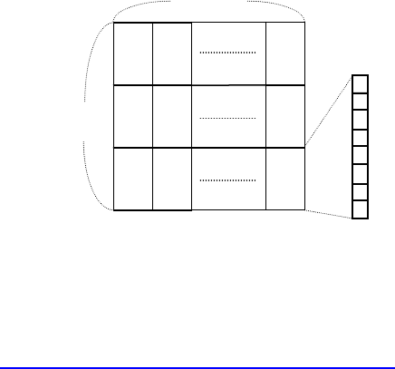
- 44 -
ESC - n
CT-S280 CT-S300 CT-S2000 CT-S4000 BD2-2220 CT-S310
support model PMU2XXX
[Function] Specifying /canceling underline
[Code] <1B>H<2D>H<n>
[Range] 0≦n≦2、48≦n≦50
[Outline] [The specification which is common to the model]
Specifying /canceling an underline.
n Function
0,48 Canceling underline
1,49 Setting 1-dot width underline
2,50 Setting 2-dot width underline
[Caution] • An underline is attached to the full character width. It is, however, not attached to the part having
been skipped by horizontal tab (HT) command.
• An underline is not attached to 90°-right-turned characters and white-on-black character.
• Underline can also be specified/canceled by ESC ! but the setting of command last processed is
valid.
• Specifying/canceling by this command is not valid for kanji.
• Underline width is constant in the specified thickness regardless of the character size.
[Default] n=0
Underline canceled
Underline specified
AAAAAAAAAA
[See Also] ESC !、FS -
[Sample Program] [Print Results]
LPRINT CHR$(&H1B);"-"; CHR$(0);
LPRINT "AAAAA";
LPRINT CHR$(&H1B);"-"; CHR$(1);
LPRINT "AAAAA"; CHR$(&HA);

- 45 -
ESC ? n
CT-S280 CT-S300 CT-S2000 CT-S4000 BD2-2220 CT-S310
support model PMU2XXX
[Function] Deleting download characters
[Code] <1B>H<3F>H<n>
[Range] 32≦n≦126
[Outline] [The specification which is common to the model]
Deletes the downloaded characters of specified code.
[Caution] • The character “n” indicates the character code used to delete the defined pattern. After the
deletion, characters are printed in the same pattern as the internal characters.
• This command deletes the code-defined pattern of the character font selected by ESC !.
• This command is ignored if the specified character code is undefined.
[See Also] ESC &、ESC %
- 46 -
ESC E n
CT-S280 CT-S300 CT-S2000 CT-S4000 BD2-2220 CT-S310
support model PMU2XXX
[Function] Specifying/canceling emphasis printing
[Code] <1B>H<45>H<n>
[Range] 0≦n≦255
[Outline] [The specification which is common to the model]
Specifying/canceling the emphasized characters.
• “n” is valid only for the lowest bit (n0).
• Control by the lowest bit (n0) is shown as follows:
n0 Function
0 Canceling emphasis printing
1 Specifying emphasis printing
[Caution] • Emphasis printing can also be specified/canceled by ESC ! but the setting of command last
processed is valid.
• Valid for all character types except HRI characters.
[Default] n=0
[See Also] ESC !
[Sample Program] [Print Results]
LPRINT CHR$(&H1B);"E"; CHR$(0);
AAABBB Emphasis specified
AAABBB Emphasis canceled
LPRINT "AAABBB"; CHR$(&HA);
LPRINT CHR$(&H1B);"E"; CHR$(1);
LPRINT "AAABBB"; CHR$(&HA);

- 47 -
ESC G n
CT-S280 CT-S300 CT-S2000 CT-S4000 BD2-2220 CT-S310
support model PMU2XXX
[Function] Specifying/canceling double strike printing
[Code] <1B>H<47>H<n>
[Range] 0≦n≦255
[Outline] [The specification which is common to the model]
Specifying /canceling the double strike printing.
• “n” is valid only for the lowest bit (n0).
• Control by the lowest bit (n0) is shown as follows:
n0 Function
0 Canceling double strike printing
1 Specifying double strike printing
[Caution] • With this printer, double-strike printing and emphasis printing provide completely the same
results.
• Valid for all character types except HRI characters.
[Default] n=0
[See Also] ESC E
[Sample Program] [Print Results]
LPRINT CHR$(&H1B);"G"; CHR$(0); AAABBB Double strike printing canceled
AAABBB Double strike printing specified
LPRINT "AAABBB"; CHR$(&HA);
LPRINT CHR$(&H1B);"G"; CHR$(1);
LPRINT "AAABBB"; CHR$(&HA);
- 48 -
ESC M n
CT-S280 CT-S300 CT-S2000 CT-S4000 BD2-2220 CT-S310
support model PMU2XXX
[Function] Selection of character fonts
[Code] <1B>H<4D>H<n>
[Range] 0≦n≦2、48≦n≦50
[Outline] [The specification which is common to the model]
Selects character fonts.
[The specification which depend on the model]
CT-S300/CT-S310
n Function
0,48 Selection of font A (12 x 24)
1,49 Selection of font B (9 x 17)
2,50 Selection of font C (8 x 16)
CT-S280/CT-S2000/CT-S4000/BD2-2220/PMU2XXX
n Function
0,48 Selection of font A (12 x 24)
1,49 Selection of font B (9 x 24)
2,50 Selection of font C (8 x 16)
[Caution] • ESC ! can also select fonts, but the setting made by the command that has last been processed
becomes valid.
[Default] n=0
[See Also] ESC!

- 49 -
ESC R n
CT-S280 CT-S300 CT-S2000 CT-S4000 BD2-2220 CT-S310
support model PMU2XXX
[Function] Selecting the international character set
[Code] <1B>H<52>H<n>
[Range] CT-S280/CT-S300/BD2-2220/PMU2XXX
0≦n≦13
CT-S2000/CT-S4000/CT-S310
0≦n≦15
[Outline] [The specification which is common to the model]
Depending on the value of “n”, one of the following character sets is specified;
n Character Set n Character Set
0 U.S.A. 8 Japan
1 France 9 Norway
2 Germany 10 Denmark II
3 U.K. 11 Spain II
4 Denmark I 12 Latin America
5 Sweden 13 Korea
6 Italy 14 Croatia
7 Spain I 15 China
[Default] standard specifications:
n = 0 (Overseas), n = 8 (Domestic)
Hangul specifications:
n=13
Chinese specifications:
CT-S300/CT-S310
n=0
CT-S2000
n=15(CT-S2000)
[See Also] 3.2 “International Character Code Table”
- 50 -
ESC V n
CT-S280 CT-S300 CT-S2000 CT-S4000 BD2-2220 CT-S310
support model PMU2XXX
[Function] Specifying/canceling 90°-right-turned characters
[Code] <1B>H<56>H<n>
[Range] 0≦n≦1、48≦n≦49
[Outline] [The specification which is common to the model]
Specifying/canceling 90°-right-turned characters.
n Function
0,48 Canceling 90°-right-turned characters
1,49 Specifying 90°-right-turned characters
[Caution] • No underlines are attached to 90°-right-turned characters.
• This command does not affect PAGE MODE but setting is maintained.
[Default] n=0
[Sample Program]
LPRINT CHR$(&H1B);"V"; CHR$(0);
LPRINT "AAAAA";
LPRINT CHR$(&H1B);"V"; CHR$(1);
LPRINT "AAAAA"; CHR$(&HA);
[Print Results]
90° rotation canceled
90° rotation specified
- 51 -
ESC t n
CT-S280 CT-S300 CT-S2000 CT-S4000 BD2-2220 CT-S310
support model PMU2XXX
[Function] Selecting the character code table
[Code] <1B>H<74>H<n>
[Range] 0≦n≦9、16≦n≦19、n=26、40、255
[Outline] [The specification which is common to the model]
Selecting the character code table.
The character code table is selected based on the value of “n”.
n Character Code Table n Character Code Table
0 Codepage PC437 7,17 Codepage PC866
1 Katakana 8 Codepage PC857
2 Codepage PC850 9,16 Windows code
3 Codepage PC860 19 Codepage PC858
4 Codepage PC863 26 Thai code 18
5 Codepage PC865 40 Codepage PC864
6,18 Codepage PC852 255 Space page (For user setting)
[Default] n=0 (Overseas)
n=1 (Domestic)
[Sample Program] [Print Results]
LPRINT CHR$(&H1B);"t"; CHR$(0);
LPRINT "n=0 "; n=0
FOR C=&HB1 TO &HB5
LPRINT CHR$(C); n=1 アイウエオ
NEXT C
LPRINT CHR$(&HA);
LPRINT CHR$(&H1B);"t"; CHR$(1);
LPRINT "n=1 ";
FOR C=&HB1 TO &HB5
LPRINT CHR$(C);
NEXT C
LPRINT CHR$(&HA);
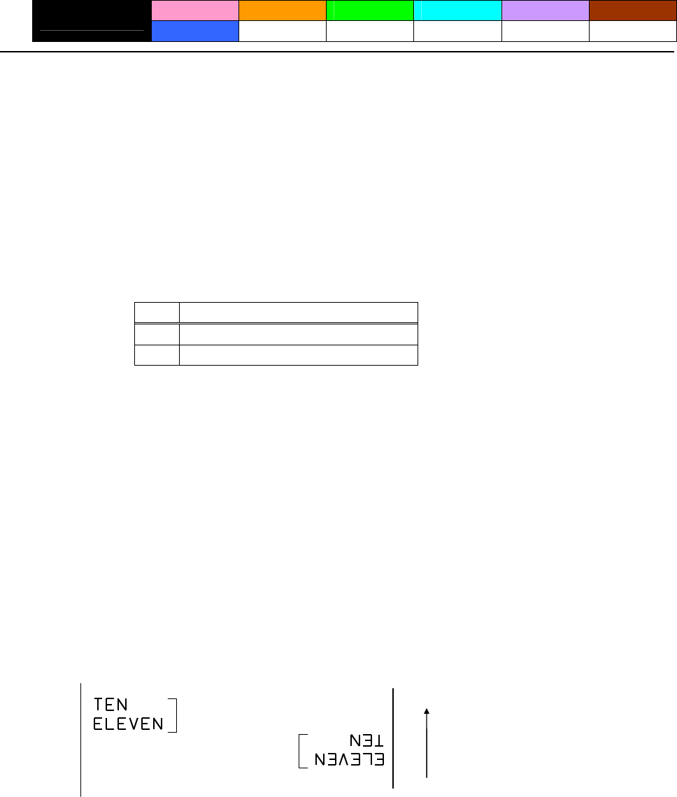
- 52 -
ESC { n
CT-S280 CT-S300 CT-S2000 CT-S4000 BD2-2220 CT-S310
support model PMU2XXX
[Function] Specifying/canceling the inverted characters
[Code] <1B>H<7B>H<n>
[Range] 0≦n≦255
[Outline] [The specification which is common to the model]
• “n” is valid only for the lowest bit (n0).
• Rotate data in the line by 180 degrees and print it.
• Control by the lowest bit (n0) is shown as follows:
n0 Function
0 Canceling inverted characters.
1 Specifying inverted characters.
[Caution] • This command is valid only when it is specified at the beginning of a line.
• This command does not affect the PAGE MODE.
[Default] n=0
[Sample Program]
LPRINT CHR$(&H1B) ;"{"; CHR$(0);
LPRINT "TEN"; CHR$(&HA);
LPRINT "ELEVEN"; CHR$(&HA);
LPRINT CHR$(&H1B) ;"{"; CHR$(1);
LPRINT "TEN"; CHR$(&HA);
LPRINT "ELEVEN"; CHR$(&HA);
[Print Results]
Inversion canceled
Inversion specified Paper feed direction
- 53 -
ESC ~ J n (Valid in CBM-270-Compatible Mode)
CT-S280 CT-S300 CT-S2000 CT-S4000 BD2-2220 CT-S310
support model PMU2XXX
[Function] Specifies/cancels printing in red (black-based paper)
[Code] <1B>H<7E>H<4A>H<n>
[Range] 0≦n≦255
[Outline] Specifies or cancels printing in red.
• Red printing is valid on black-based thermal paper. Specifies or cancels printing in black on
red-based thermal paper.
• “n” is valid only for the lowest bit (n0).
• Control by the lowest bit (n0) is shown as follows:
Function
n0 black-based paper red-based paper
0 Canceling red printing. Canceling black printing.
1 Specifying red printing. Specifying black printing.
[Caution] • Valid when 2-color paper is specified by the GS ( E command.
• Valid only when dedicated thermal paper is used.
• This command must not be used for normal thermal paper.
• Conducting pulse amount after cancellation is standard value. At the time of setting, conducting
pulse amount is increased to change the coloring.
[Default] n=0
[Sample Program]
LPRINT CHR$(&H1B);"~";"J"; CHR$(1);
LPRINT "AAAAA"; CHR$(&HA);
LPRINT CHR$(&H1B);"~";"J"; CHR$(0);
LPRINT "AAAAA"; CHR$(&HA);
[Print Results]
AAAAA
AAAAA Red printing
Black printing
* When dedicated thermal paper (black-based paper) is used.
- 54 -
ESC ~ J n (Valid in CBM1000-Compatible Mode)
CT-S280 CT-S300 CT-S2000 CT-S4000 BD2-2220 CT-S310
support model PMU2XXX
[Function] Specifies/cancels printing in red (black-based paper)
[Code] <1B>H<7E>H<4A>H<n>
[Range] 0≦n≦255
[Outline] [The specification which is common to the model]
Specifies or cancels printing in red.
• Red printing is valid on black-based thermal paper. Specifies or cancels printing in black on
red-based thermal paper.
• “n” is valid only for the lowest bit (n0).
• Control by the lowest bit (n0) is shown as follows:
Function
n0 black-based paper red-based paper
0 Specifying red printing. Specifying black printing.
1 Canceling red printing. Canceling black printing.
[Caution] • Valid when 2-color paper is specified by the GS ( E command.
• Valid only when dedicated thermal paper is used.
• This command must not be used for normal thermal paper.
• Conducting pulse amount after cancellation is standard value. At the time of setting, conducting
pulse amount is increased to change the coloring.
[Default] n=0
[Sample Program]
LPRINT CHR$(&H1B);"~";"J"; CHR$(1);
LPRINT "AAAAA"; CHR$(&HA);
LPRINT CHR$(&H1B);"~";"J"; CHR$(0);
LPRINT "AAAAA"; CHR$(&HA);
[Print Results]
Black printing
Red printing
AAAAA
AAAAA
* When dedicated thermal paper (black-based paper) is used.

- 55 -
DC3 n (Valid in CBM-270-Compatible Mode)
CT-S280 CT-S300 CT-S2000 CT-S4000 BD2-2220 CT-S310
support model PMU2XXX
[Function] Specifies/cancels printing in red (black-based paper)
[Code] <13>H<n>
[Range] 0≦n≦255
[Outline] Specifies or cancels printing in red.
• Red printing is valid on black-based thermal paper. Specifies or cancels printing in black on
red-based thermal paper.
• “n” is valid only for the lowest bit (n0).
• Control by the lowest bit (n0) is shown as follows:
Function
n0 black-based paper red-based paper
0 Canceling red printing. Canceling black printing.
1 Specifying red printing. Specifying black printing.
[Caution] • Valid only at the top of a line.
• Valid only when dedicated thermal paper is used.
• This command must not be used for normal thermal paper.
• Conducting pulse amount after cancellation is standard value. At the time of setting, conducting
pulse amount is increased to change the coloring.
[Default] n=0
[Sample Program]
LPRINT CHR$(&H13); CHR$(1);
LPRINT "AAAAA"; CHR$(&HA);
LPRINT CHR$(&H13); CHR$(0);
LPRINT "AAAAA"; CHR$(&HA);
[Print Results]
Red printing
AAAAA
AAAAA
Black printing
* When dedicated thermal paper (Black-based paper) is used.
- 56 -
DC3 n (Valid in CBM1000-Compatible Mode)
CT-S280 CT-S300 CT-S2000 CT-S4000 BD2-2220 CT-S310
support model PMU2XXX
[Function] Specifies/cancels printing in red (black-based paper)
[Code] <13>H<n>
[Range] 0≦n≦255
[Outline] [The specification which is common to the model]
Specifies or cancels printing in red.
• Red printing is valid on black-based thermal paper. Specifies or cancels printing in black on
red-based thermal paper.
• “n” is valid only for the lowest bit (n0).
• Control by the lowest bit (n0) is shown as follows:
Function
n0 black-based paper red-based paper
0 Specifying red printing. Specifying black printing.
1 Canceling red printing. Canceling black printing.
[Caution] • Valid when 2-color paper is specified by the GS ( E command.
• Valid only at the top of a line.
• Valid only when dedicated thermal paper is used.
• This command must not be used for normal thermal paper.
• Conducting pulse amount after cancellation is standard value. At the time of setting, conducting
pulse amount is increased to change the coloring.
[Default] n=0
[Sample Program]
LPRINT CHR$(&H13); CHR$(1);
LPRINT "AAAAA"; CHR$(&HA);
LPRINT CHR$(&H13); CHR$(0);
LPRINT "AAAAA"; CHR$(&HA);
[Print Results]
Black printing
Red printing
AAAAA
AAAAA
* When dedicated thermal paper (Black-based paper) is used.
- 57 -
GS ! n
CT-S280 CT-S300 CT-S2000 CT-S4000 BD2-2220 CT-S310
support model PMU2XXX
[Function] Specifying the character size
[Code] <1D>H<21>H<n>
[Range] 0≦n≦255
Where: 1≤vertical magnification≤8, 1≤horizontal magnification≤8
[Outline] [The specification which is common to the model]
Specifies the character size (Vertical and horizontal magnification).
Value
Bit Function Hex. Number Decimal Number
0
1
2
Vertical magnification
specification Refer to Table 2, “Vertical Magnification”.
3
4
5
6
Horizontal magnification
specification Refer to Table 1, “Horizontal Magnification”.
7
Table 1 Horizontal Magnification Table 2 Vertical Magnification
Hex. Decimal Magnification Hex. Decimal Magnification
00 0 1 x (Standard) 00 0 1 x (Standard)
10 16 2 x (Double width) 01 1 2 x (Double )
20 32 3 x 02 2 3 x
30 48 4 x 03 3 4 x
40 64 5 x 04 4 5 x
50 80 6 x 05 5 6 x
60 96 7 x 06 6 7 x
70 112 8 x 07 7 8 x

- 58 -
[Caution] [The specification which is common to the model]
• This command is valid for all characters (alphanumeric, kana, and kanji) except for HRI
characters.
• This command is ignored if either the vertical magnification or horizontal magnification is out of
the defined range.
• In PAGE MODE, the vertical direction means the top-bottom direction of each character. The
horizontal direction means the side-to-side direction of each character. If characters of different
vertical magnification are contained in a line, the baseline of each character is lined up.
• Horizontal and vertical magnification can also be specified/canceled by ESC ! but the setting of
command last processed is valid.
• In STANDARD MODE, the vertical direction is defined as the paper feed direction, and the
horizontal direction is defined as the direction perpendicular to the paper feed.
[The specification which depend on the model]
CT-S280/CT-S300/CT-S2000/CT-S4000/CT-S310
• Setting memory SW 3-7 to ON allows the horizontal and vertical relations to be interchanged
when 90°-right-turnning of character is specified.
[Default] n=0
[See Also] ESC !
- 59 -
GS B n
CT-S280 CT-S300 CT-S2000 CT-S4000 BD2-2220 CT-S310
support model PMU2XXX
[Function] Specifying/canceling the black/white inverted printing
[Code] <1D>H<42>H<n>
[Range] 0≦n≦255
[Outline] [The specification which is common to the model]
This command specifies or cancels the black/white inverted printing.
• “n” is valid only for the lowest bit (n0).
• Control by the lowest bit (n0) is shown as follows:
n0 Function
0 The black/white inverted printing is canceled.
1 The black/white inverted printing is specified.
[Caution] • The black/white inversion works on internal and downloaded characters.
• The black/white inversion works also on the right spacing of characters defined by ESC SP.
• This command does not affect the bit image, downloaded bit image, bar code, HRI characters, or
the skip area specified by HT, ESC $, or ESC
\
.
• This command does not affect the space between lines.
• Black/white inversion specification takes precedence over underline specification. Underline
printing specified is, therefore, nullified if black/white inversion is specified; the underline setting,
however, remains unchanged.
[Default] n=0

- 60 -
GS b n
CT-S280 CT-S300 CT-S2000 CT-S4000 BD2-2220 CT-S310
support model PMU2XXX
[Function] Specifying/canceling the smoothing
[Code] <1D>H<62>H<n>
[Range] 0≦n≦255
[Outline] [The specification which is common to the model]
This command specifies or cancels the smoothing.
• “n” is valid only for the lowest bit (n0).
• Control by the lowest bit (n0) is shown as follows:
n0 Function
0 The smoothing is canceled.
1 The smoothing is specified.
[Caution] • Smoothing is effective to printer’s internal characters, download characters, and non-standard
characters.
• Smoothing is not effective to characters with either of their vertical or horizontal magnification is
x1.
[Default] n=0
[See Also] ESC! 、GS !
- 61 -
2.2.4 Print Position Commands
HT
CT-S280 CT-S300 CT-S2000 CT-S4000 BD2-2220 CT-S310
support model PMU2XXX
[Function] Horizontal tab
[Code] <09>H
[Outline] [The specification which is common to the model]
Shifts the printing position to the next horizontal tab position.
• Ignored when the next horizontal tab position has not been set.
[Caution] The horizontal tab position is set by ESC D.
[Default] At the selection of font A, tabs are set every 8 characters (at 9th, 17th, 25th, ...) with right space
amount of a character set at 0 and horizontal enlargement rate of a character set at 1.
[See Also] ESC D
[Sample Program]
LPRINT "012345678901234567890"; CHR$(&HA);
LPRINT CHR$(&H9);"AAA";
LPRINT CHR$(&H9);"BBB"; CHR$(&HA);
LPRINT CHR$(&H1B);"D";
LPRINT CHR$(3); CHR$(7); CHR$(14); CHR$(0);
LPRINT CHR$(&H9);"AAA";
LPRINT CHR$(&H9);"BBB";
LPRINT CHR$(&H9);"CCC"; CHR$(&HA);
[Printing Result]
012345678901234567890
When set to the 4th, 8th, and 15th columns
Initially set horizontal tab
AAA BBB
AAA BBB CCC

- 62 -
ESC $ n1 n2
CT-S280 CT-S300 CT-S2000 CT-S4000 BD2-2220 CT-S310
support model PMU2XXX
[Function] Specifying the absolute positions
[Code] <1B>H<24>H<n1><n2>
[Range] 0≦n1≦255
0≦n2≦255
[Outline] [The specification which is common to the model]
The printing start position is specified by the absolute position from the left margin with the number
of dots divided by 256 and quotient specified as “n2” and remainder as “n1”. Therefore, the printing
start position is designated as n1+n2×256×basic calculation pitch from the left margin.
[Caution] • The basic calculation pitch is set by GS P. After the line feed width is set, if the basic calculation by
GS P leaves a fraction, the fraction is corrected with the minimum pitch of the mechanism, and the
remainder is omitted.
• In STANDARD MODE, this command uses the horizontal (Paper feed direction) basic calculation
pitch (x).
• In PAGE MODE, this command acts differently depending on the start point:
(1) If the start point specified by ESC T is top right or bottom left, the command uses the vertical
(Paper feed direction) basic calculation pitch (y).
(2) If the start point specified by ESC T is top left or bottom right, the command uses the
horizontal (Perpendicular to the paper feed direction) basic calculation pitch (x). Specification
beyond the end of the line is ignored.
[See Also] ESC
\
、GS P、GS
\
、GS $
[Sample Program] [Print Results]
Absolute position specified
LPRINT CHR$(&H1B);"$";
0 50 100 256
LPRINT CHR$(0); CHR$(0);"A";
A B A
A B C
LPRINT CHR$(&H1B);"$";
LPRINT CHR$(50); CHR$(0);"B";
LPRINT CHR$(&H1B);"$";
LPRINT CHR$(0); CHR$(1);"C"; CHR$(&HA);
LPRINT CHR$(&H1B);"$";
-62
LPRINT CHR$(100); CHR$(0);"A";
Relative position specified
LPRINT CHR$(&H1B);"
\
";
LPRINT CHR$(&HC2); CHR$(&HFF);"B"; CHR$(&HA);

- 63 -
ESC D [n]k NULL
CT-S280 CT-S300 CT-S2000 CT-S4000 BD2-2220 CT-S310
support model PMU2XXX
[Function] Setting horizontal tab position
[Code] <1B>H<44>H[<n>]k<00>H
[Range] 1≦n≦255
0≦k≦32
[Outline] [The specification which is common to the model]
Specifying a horizontal tab position.
• “n” indicates the number of columns from the beginning to the horizontal tab position. Note,
however, that “n = set position – 1”. For example, to set the position at 9th column, n = 8 is to be
specified.
• “k” denotes the number of horizontal tab positions you want to set.
• The tab position is set at a position where it is “character width ×n” from the beginning of a line.
The character width, at this time, includes the space on the right. In double width characters, it is
made double the ordinary case.
• Tab positions that can be specified are maximum 32. Specifying tab positions exceeding this limit
is ignored.
• <n> k, which denotes a setting position, is input in the increasing order and ends at <00> H.
• ESC D <NULL> clears all the set tab positions. Following clearing, the horizontal tab command is
ignored.
[Caution] • When the data, <n> k, is equal to or smaller than its preceding data, <n> k-1, it is assumed that
tab setting is finished. If this is the case, the next data onward will be processed as normal data.
• When the data, <n> k, exceeds a 1-line print area, set the horizontal tab position, as “Set column
position = Maximum print columns + 1”.
• The horizontal tab position does not change even if the character width is altered after setting the
horizontal tab position.
[Default] At the selection of font A, tabs are set every 8 characters (at 9th, 17th, 25th, ...) with right space
amount of a character set at 0 and horizontal enlargement rate of a character set at 1.
[See Also] HT
[Sample Program]
Refer to Sample Program and Print Results for HT.
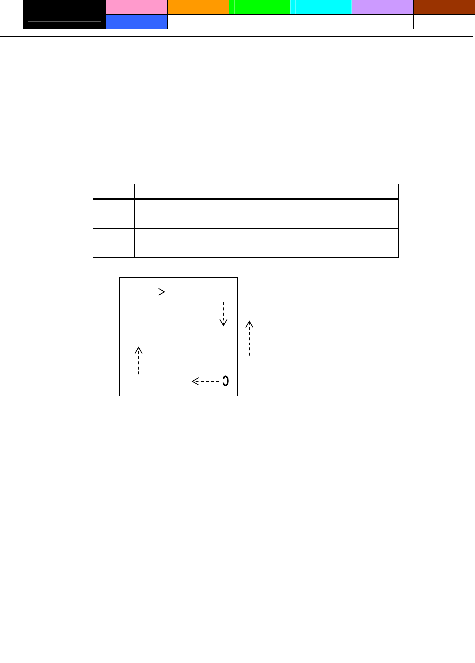
- 64 -
ESC T n
CT-S280 CT-S300 CT-S2000 CT-S4000 BD2-2220 CT-S310
support model PMU2XXX
[Function] Selecting the character printing direction in PAGE MODE
[Code] <1B>H<54>H<n>
[Range] 0≦n≦3、48≦n≦51
[Outline] [The specification which is common to the model]
Selects the direction and start point of character printing in PAGE MODE.
n Printing Direction Start Point
0,48 Left to right Top left (“A” in the figure)
1,49 Bottom to top Bottom left (“B” in the figure)
2,50 Right to left Bottom right (“C” in the figure)
3,51 Top to bottom Top right (“D” in the figure)
A
Paper feed direction
D
B
[Caution] • When STANDARD MODE is selected, this command only executes the internal flagging of the
printer without affecting the printing in STANDARD MODE.
• The character mapping position will be the start point of the print area specified by ESC W.
• The basic calculation pitch (x or y) used by the following commands varies with the start point.
(1) If the start point is the top left or bottom right (The characters are mapped in the direction
perpendicular to the paper feed),
• Commands using x: ESC SP, ESC S, ESC
\
• Commands using y: ESC 3, ESC J, GS $, GS
\
(2) If the start point is the top right or bottom left (The characters are mapped in the paper feed
direction),
• Commands using x: ESC 3, ESC J, GS $, GS
\
• Commands using y: ESC SP, ESC S, ESC
\
[Default] n=0
[See Also] Appendix 5.1 “Explanation on PAGE MODE”
ESC $, ESC L, ESC W, ESC
\
, GS $, GS P, GS
\
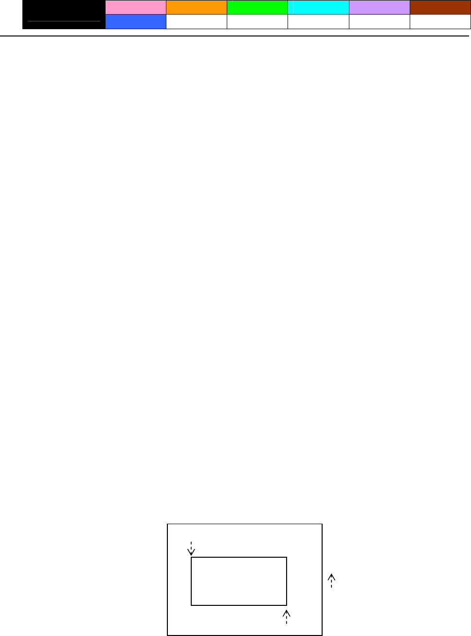
- 65 -
ESC W xL xH yL yH dxL dxH dyL dyH
CT-S280 CT-S300 CT-S2000 CT-S4000 BD2-2220 CT-S310
support model PMU2XXX
[Function] Defining the print area in PAGE MODE
[Code] <1B>H<57>H<xL><xH><yL><yH><dxL><dxH><dyL><dyH>
[Range] 0≦xL、xH、yL、yH、dxL、dxH、dyL、dyH ≦255
except for dxL = dxH = 0 or dyL = dyH = 0
[Outline] [The specification which is common to the model]
Defines the location and size of the print area.
• Horizontal start point = [(xL+xH×256)×basic calculation pitch] inches
• Vertical start point = [(yL+yH×256)×basic calculation pitch] inches
• Horizontal length = [(dxL+dxH×256)×basic calculation pitch] inches
• Vertical length = [(dyL+dyH×256)×basic calculation pitch] inches
[Caution] • When STANDARD MODE is selected, this command only executes the internal flagging of the
printer without affecting the printing in STANDARD MODE.
• If the horizontal start point or vertical start point is out of the printable area, this command is
canceled and the next data is handled as normal data.
• If the horizontal length or vertical length is 0, this command is canceled and the next data is
handled as normal data.
• The character mapping position will be the start point specified by ESC T in the print area.
• If the “horizontal start point + horizontal length” is greater than the horizontal printable area, the
“horizontal printable area – horizontal start point” is taken as the horizontal length.
• If the “vertical start point + vertical length” is greater than the vertical printable area, the “vertical
printable area – vertical start point” is taken as the vertical length.
• The basic calculation pitch is defined by GS P. Once defined, the print area is not changed if the
basic calculation pitch is changed by GS P.
• Fractions resulting from calculations are corrected with the minimum pitch of the mechanism, and
the remainder is omitted.
• The horizontal start point and horizontal length are calculated with the basic calculation pitch (x).
The vertical start point and vertical length are calculated with the basic calculation pitch (y).
• The figure below illustrates the print area, where X = horizontal start point, Y = vertical start point,
Dx = horizontal length, and Dy = vertical length.
(X、Y) Paper
Dx
Dy Prin
• The printable area is approximately 117 mm (938/203 inches) vertically, and horizontal area
depends on the model. (Refer to the below Table)
t
(X+Dx-1、Y+Dy-1)
Pa
p
er feed direction
- 66 -
[Default] xL=xH=yL=yH=0
dyL=126、dyH=6
dxL,dyH depends on paper width. (Refer to the below Table)
paper
width print width/(dot) dxL dxH support model
112mm 104mm/(832) 96 3 CT-S4000
112mm 90mm/(720) 208 2 CT-S4000
83mm 82.5mm/(660) 148 2 CT-S4000
83mm 80mm/(640) 128 2 CT-S4000/CT-S2000
80mm 72mm/(576) 64 2
CT-S4000/CT-S2000/CT-S300/
BD2-2220/CT-S310/PMU2XXX
80mm 64mm/(512) 0 2 CT-S4000/CT-S2000/CT-S300/CT-S310
60mm 54.5mm/(436) 180 1 CT-S2000
58mm 54mm/(432) 176 1 CT-S2000/BD2-2220/PMU2XXX
58mm 52.5mm/(420) 156 1 CT-S2000
58mm 48mm/(384) 128 1 CT-S2000/CT-S300/CT-S280/CT-S310
58mm 45mm/(360) 104 1 CT-S2000/CT-S300/CT-S310
[See Also] Appendix 5.1 “Explanation on PAGE MODE”
CAN、ESC L、ESC T、GS P

- 67 -
ESC
\
nL nH
CT-S280 CT-S300 CT-S2000 CT-S4000 BD2-2220 CT-S310
support model PMU2XXX
[Function] Specifying the relative position
[Code] <1B>H<5C>H<nL><nH>
[Range] 0≦nL≦255
0≦nH≦255
[Outline] [The specification which is common to the model]
This command specifies the next print start position in a relative position with respect to the current
position. The next print start position will be at a point of [(nL+nH×256)×basic calculation pitch]
inches away from the current position.
[Caution] • Specification of a position outside the print area is ignored.
• If a new position is specified to the right of the current position in the direction of printing, it should
be specified as positive (+). If it is to the left, it should be as negative (–).
• A negative value is the complement of 65536. For example, to move the position by N pitches to
the left, specify it as: nL + nH x 256 = 65536 – N
• Fractions resulting from calculation are corrected with the minimum pitch of the mechanism, and
the remainder is omitted.
• In STANDARD MODE, this command uses the horizontal basic calculation pitch (x).
• In PAGE MODE, this command acts differently depending on the start point:
(1) If the start point specified by ESC T is top left or bottom right, the command specifies the
relative position in the direction perpendicular to the paper feed (The character’s side-to-side
direction), using the horizontal basic calculation pitch (x).
(2) If the start point is top right or bottom left, the command specifies the relative position in the
paper feed direction (The character’s side-to-side direction), using the vertical basic calculation
pitch (y).
[See Also] ESC $、GS P
[Sample Program]
Refer to Sample Program and Print Results for ESC $.
- 68 -
ESC a n
CT-S280 CT-S300 CT-S2000 CT-S4000 BD2-2220 CT-S310
support model PMU2XXX
[Function] Aligning the characters
[Code] <1B>H<61>H<n>
[Range] 0≦n≦2、48≦n≦50
[Outline] [The specification which is common to the model]
All the printed data within one line are aligned in the specified position.
Depending on the value “n”, positional alignment is carried out as shown in the table below:
n Position
0,48 Left end alignment
1,49 Centering
2,50 Right end alignment
[Caution] • This command is valid only when it is inputted at the beginning of a line.
• This command does not affect the PAGE MODE.
• Executes justification in the print area being set.
[Default] n=0
[Sample Program]
LPRINT CHR$(&H1B);"a"; CHR$(0);
LPRINT "AAAAA"; CHR$(&HA);
LPRINT CHR$(&H1B);"a"; CHR$(1);
LPRINT "AAAAA"; CHR$(&HA);
LPRINT CHR$(&H1B);"a"; CHR$(2);
LPRINT "AAAAA"; CHR$(&HA);
[Print Results]
AAAAA
AAAAA
AAAAA
Paper feed direction
Left-justified Centered Right-justified

- 69 -
GS $ nL nH
CT-S280 CT-S300 CT-S2000 CT-S4000 BD2-2220 CT-S310
support model PMU2XXX
[Function] Specifying the absolute position of character vertical direction in PAGE MODE
[Code] <1D>H<24>H<nL><nH>
[Range] 0≦nL≦255、0≦nH≦255
[Outline] [The specification which is common to the model]
Specifies the vertical position of character at the start point of data development in PAGE MODE
using absolute position based on the start position. The position of vertical direction of character at
the start position of next data development is the position [(nL+nH×256)×basic calculation pitch]
from the start position.
[Caution] • This command is ignored except at PAGE MODE selection.
• Absolute position setting exceeding the specified print area is ignored.
• Position in horizontal direction of character at the start position of data development is not shifted.
• Start point used as the reference is set by ESC T.
• The following operation occurs at the start point of ESC T.
(1) When start point is set at “upper left” or “lower right”, the absolute position of paper feed
direction (vertical direction of character) is set. In this case, basic calculation pitch (y) of
vertical direction is used.
(2) When start point is set at “upper right” or “lower left”, the absolute position of vertical
direction of paper feed (vertical direction of character) is set. In this case, basic calculation
pitch (x) of horizontal direction is used.
• Basic calculation pitch is set by GS P.
• When fractional number is caused by the calculation, it is corrected by the minimum pitch of
mechanism and the rest is discarded.
[See Also] ESC $, ESC T, ESC W, ESC
\
, GS P, GS
\
- 70 -
GS L nL nH
CT-S280 CT-S300 CT-S2000 CT-S4000 BD2-2220 CT-S310
support model PMU2XXX
[Function] Setting the left margin
[Code] <1D>H<4C>H<nL><nH>
[Range] 0≦nL≦255、0≦nH≦255
[Outline] [The specification which is common to the model]
This command sets the left margin specified by nL and nH.
The value of the left margin is [(nL + nH x 256) x basic calculation pitch] inches.
Printable area
Left margin Print area width
[Caution] • This command only works when it is entered at the beginning of a line.
• When PAGE MODE is selected, this command only executes the internal flagging of the printer.
• The setting of this command does not affect PAGE MODE.
• The maximum settable left margin is equal to the horizontal printable area. A setting greater than
this maximum is trimmed to the maximum.
• The basic calculation pitch is defined by GS P. Once defined, the left margin is not changed if the
basic calculation pitch is changed by GS P.
• The left margin is calculated with the horizontal basic calculation pitch (x) set by GS P. A fraction
resulting from the calculation is corrected with the minimum pitch of the mechanism, and the
remainder is omitted.
• When mapping character data, if the print area specified is not wide enough to accommodate one
character of the current font, only the line for that character data is handled as follows:
(1) The print area is extended toward the right to be equivalent to one character of the current
font, but not wider than the printable area.
(2) If an area for one character cannot be provided as a result of step (1), the print area is
extended toward the left. (So, the left margin is decreased.)
• When mapping non-character data (bit image, downloaded bit image, or bar code), if the print
area specified is narrower than 9-bits, only the line for that data is handled as follows:
(1) The print area is extended toward the left (so, the left margin is decreased) until it is 9-dot
wide, but not wider than the printable area.
[Default] nL=0、nH=0
[See Also] GS P、GS W
- 71 -
GS W nL nH
CT-S280 CT-S300 CT-S2000 CT-S4000 BD2-2220 CT-S310
support model PMU2XXX
[Function] Setting the print area width
[Code] <1D>H<57>H<nL><nH>
[Range] 0≦nL≦255
0≦nH≦255
[Outline] [The specification which is common to the model]
Sets the print area width specified by nL and nH.
The print area width will be [(nL+nH×256)×basic calculation pitch] inches.
Printable area
Left margin Print area width
[Caution] • This command only works when it is entered at the beginning of a line.
• When PAGE MODE is selected, this command only executes the internal flagging of the printer.
• The setting of this command does not affect PAGE MODE.
• If the value entered with this command exceeds the printable area for one line, the entire area
except the left margin is set as the print area width.
• The basic calculation pitches are defined by GS P. Once defined, the print area width is not
changed if the basic calculation pitch is changed by GS P.
• The print area width is calculated with the horizontal basic calculation pitch (x) defined by GS P. A
fraction resulting from the calculation is corrected with the minimum pitch of the mechanism, and
the remainder is omitted.
• If the first character to be mapped at the beginning of a line has a width (including the right
spacing) greater than the print area width, only that line is handled as follows:
(1) The print area is extended toward the right to accommodate the first character, but not wider
than the printable area.
Printable area
A
(1) Extended toward the right
Left margin
Print area width
- 72 -
(2) If a sufficient area cannot be provided as a result of step (1), the print area is extended
toward the left (so, the left margin is decreased).
Printable area
A
Left margin (1) Extended
(2) The left margin is trimmed toward the right
Print area width
(3) If a sufficient area cannot be provided as a result of step (2), the right spacing is trimmed.
• When mapping a bit image (or downloaded bit image), if the print area is narrower than the
minimum width of the bit image (two dots for single density, or one dot for double density), only
the line for that image is handled as follows:
(1) The print area is extended toward the left (so, the left margin is decreased) until it is equal to
the minimum width of the image, but not wider than the printable area.
[Default]
paper
width print width/(dot) nL nH support model
CT-S4000 112mm 104mm/(832) 96 3
CT-S4000 112mm 90mm/(720) 208 2
83mm 82.5/(660) 148 2 CT-S4000
83mm 80mm/(640) 128 2 CT-S4000/CT-S2000/CT-S300/CT-S310
80mm 72mm/(576) 64 2
CT-S4000/CT-S2000/CT-S300/
BD2-2220/CT-S310/PMU2XXX
80mm 64mm/(512) 0 2 CT-S4000/CT-S2000/CT-S300/CT-S310
60mm 54.5mm/(436) 180 1 CT-S2000
58mm 54mm/(432) 176 1 CT-S2000/BD2-2220/PMU2XXX
58mm 52.5mm/(420) 156 1 CT-S2000
58mm 48mm/(384) 128 1 CT-S2000/CT-S300/CT-S280/CT-S310
58mm 45mm/(360) 104 1 CT-S2000/CT-S300/CT-S310
[See Also] GS L、GS P

- 73 -
GS
\
nL nH
CT-S280 CT-S300 CT-S2000 CT-S4000 BD2-2220 CT-S310
support model PMU2XXX
[Function] Specifying the relative vertical position of a character in PAGE MODE
[Code] <1D>H<5C>H<nL><nH>
[Range] 0≦nL≦255、0≦nH≦255
[Outline] [The specification which is common to the model]
This command is used in PAGE MODE to specify the vertical position of a character in the data
mapping start position, in a relative position with respect to the current position. The next data
mapping start position will be at a point [(nL+nH×256)×basic calculation pitch] inches away from
the current position.
[Caution] • This command is ignored when PAGE MODE is not selected.
• If a new position is specified for a character located beneath the current position, it should be
specified as positive (+). If it is above the current position, it should be negative (–).
• A negative value is the complement of 65536. For example, to move the position by N pitches up,
specify it as: nL + nH x 256 = 65536 – N
• The specification of a relative position outside the specified print area is ignored.
• Depending on the start point specified by ESC T, this command acts as follows:
(1) If the start point is the top left or bottom right, the command specifies the relative position in
the paper feed direction (the character’s top-bottom direction) using the vertical basic
calculation pitch (y).
(2) If the start point is the top right or bottom left, the command specifies the relative position in
the direction perpendicular to the paper feed (the character’s top-bottom direction) using the
horizontal basic calculation pitch (x).
• The basic calculation pitch is set by GS P.
• Fractions resulting from calculations are corrected with the minimum pitch of the mechanism, and
the remainder is omitted.

- 74 -
2.2.5 Line Feed Span Commands
ESC 2
CT-S280 CT-S300 CT-S2000 CT-S4000 BD2-2220 CT-S310
support model PMU2XXX
[Function] Specifying 1/6-inch line feed rate
[Code] <1B>H<32>H
[Outline] [The specification which is common to the model]
[The specification which depend on the model]
CT-S280/CT-S300/BD2-2220/CT-S310/PMU2XXX
The line feed rate per line is specified by 1/6 inch.
CT-S2000/CT-S4000
The line feed rate per line is specified by MSW5-2 setting.
[Caution] Line feed rate can be specified respectively for both STANDARD MODE and PAGE MODE.
[Default] CT-S280/CT-S300/BD2-2220/CT-S310/PMU2XXX
Approx. 4.23mm (1/360 inches)
CT-S2000/CT-S4000
(1) When memory switch 5-2 is OFF:
Approx. 4.23mm
(2) When memory switch 5-2 is ON:
Approx. 3.75 mm

- 75 -
ESC 3 n
CT-S280 CT-S300 CT-S2000 CT-S4000 BD2-2220 CT-S310
support model PMU2XXX
[Function] Setting line feed rate of minimum pitch
[Code] <1B>H<33>H<n>
[Range] 0≦n≦255
[Outline] [The specification which is common to the model]
Sets the line feed width per line to [n×basic calculation pitch] inches.
[Caution] • The line feed width can be set separately for the STANDARD and PAGE MODES.
• The basic calculation pitch is set by GS P. Once defined, the line feed width is not changed if the
basic calculation pitch is changed by GS P.
• Fractions resulting from calculation are corrected with the minimum pitch of the mechanism, and
the remainder is omitted.
• In STANDARD MODE, this command uses the vertical (paper feed direction) basic calculation pitch
(y).
• In PAGE MODE, this command acts differently depending on the start point:
(1) If the start point specified by ESC T is top left or bottom right, the command uses the vertical
(paper feed direction) basic calculation pitch (y).
(2) If the start point specified by ESC T is top right or bottom left, the command uses the
horizontal (perpendicular to the paper feed direction) basic calculation pitch (x).
• The maximum settable line feed width is 1016 mm (40 inches). A setting greater than this
maximum is trimmed to the maximum.
[Default] CT-S300/CT-S280/BD2-2220/CT-S310/PMU2XXX
Approx. 4.23mm
CT-S2000/CT-S4000
(1) When memory switch 5-2 is OFF:
Approx. 4.23mm
(2) When memory switch 5-2 is ON:
Approx. 3.75 mm
[See Also] ESC 2、GS P

- 76 -
2.2.6 Bit Image Commands
ESC * m n1 n2 [d] k
CT-S280 CT-S300 CT-S2000 CT-S4000 BD2-2220 CT-S310
support model PMU2XXX
[Function] Specifying the bit image mode
[Code] <1B>H<2A>H<m>H<n1><n2>[<d>]k
[Range] m=0、1、32、33
0≦n1≦255、0≦n2≦2
0≦d≦255
k=n1+256×n2 (m=0、1)、k=(n1+256×n2)×3 (m=32、33)
[Outline] [The specification which is common to the model]
• According to the number of dots specified in “n1”, “n2”, specify the bit image of mode “m”.
• The number of dots printed is divided by 256, whose quotient is taken as n2 and residual as “n1”.
The total number of dots printed in the horizontal direction is equal to n1+(256×n2).
• When bit image data have been input in excess of dot positions that can be printed on one line,
the excess data are discarded.
• ”d” is bit image data. Bits to be printed are specified as “1” and those not as “0”.
• The bit image modes specified by “m” are shown as follows:
Vertical Direction Horizontal Direction
m Mode Maximum
Dot Count
Dot Count Dot Density Dot Density
0 8 dot single density 8 67dpi 101dpi (1)
1 8 dot double density 8 67dpi 203dpi (2)
32 24 dot single density 24 203dpi 101dpi (3)
33 24 dot double density 24 203dpi 203dpi (4)
(1)~(4) unit: dpi
paper
width
print
width
support model (1) (2) (3) (4)
CT-S4000 112mm 104mm 416 832 416 832
CT-S4000 112mm 90mm 360 720 360 720
CT-S4000 83mm 82.5mm 330 660 330 660
CT-S4000/CT-S2000/CT-S300/CT-S310 83mm 80mm 320 640 320 640
CT-S4000/CT-S2000/CT-S300/ 80mm 72mm 286 576 286 576
BD2-2220/CT-S310/PMU2XXX
CT-S4000/CT-S2000/CT-S300/CT-S310 80mm 64mm 256 512 256 512
CT-S2000 60mm 54.5mm 218 436 218 436
CT-S2000/BD2-2220/PMU2XXX 58mm 54mm 216 432 216 432
CT-S2000 58mm 52.5mm 210 420 210 420
CT-S2000/CT-S300/CT-S280/CT-S310 58mm 48mm 192 384 192 384
CT-S2000/CT-S300/CT-S310 58mm 45mm 180 360 180 360
[Caution] • When the value of “m” is out of the above range, the data following after “n1” is processed as
normal printing data.
• After completion of bit image printing, the printer returns to normal data processing mode.
- 77 -
GS * n1 n2 [d] n1xn2x8
CT-S280 CT-S300 CT-S2000 CT-S4000 BD2-2220 CT-S310
support model PMU2XXX
[Function] Defining the download bit image
[Code] <1D>H<2A>H<n1><n2>[<d>]n1×n2×8
[Range] 1≦n1≦255
1≦n2≦48
n1×n2≦1536
[Outline] [The specification which is common to the model]
• Defines download bit images of the number of dots specified by “n1” and “n2”.
• The numbers of dots are n1×8 in horizontal direction and n2×8 in vertical direction.
• ”d” indicates bit image data.
• Once defined, the download bit image remains effective until it is redefined, ESC @, ESC &, GS (A,
or FS q, is executed, or power is turned OFF.
[Caution] [The specification which is common to the model]
• Relations between the bit image data and the dots defined are shown below.
[The specification which depend on the model]
CT-S280/CT-S300/BD2-2220/CT-S310/PMU2XXX
• With this command executed, the defined content of a downloaded character is cleared.
CT-S2000/CT-S4000
• With this command executed, the defined content of a downloaded character is not cleared.
[See Also] GS /
dn2+1
dn2+2
dn2×2
dn2×2+1
dn2×2+2
dn2×n2×8
n1×8 dots
n2×8 dots
d1
d2
dn2
MSB
LSB
- 78 -
GS / m
CT-S280 CT-S300 CT-S2000 CT-S4000 BD2-2220 CT-S310
support model PMU2XXX
[Function] Printing the downloaded bit image
[Code] <1D>H<2F>H<m>
[Range] 0≦m≦3、48≦m≦51
[Caution] [The specification which is common to the model]
Prints downloaded bit image in a mode specified by “m”.
Modes that can be selected by “m” are shown below.
Dot Density in Dot Density in
m Mode Name Vertical Direction Horizontal Direction
0,48 NORMAL MODE 203DPI 203DPI
1,49 DOUBLE WIDTH MODE 203DPI 101DPI
2,50 DOUBLE HEIGHT MODE 101DPI 203DPI
3,51 QUADRUPLE SIZE MODE 101DPI 101DPI
[Caution] • When a downloaded bit image has not been defined, this command is ignored.
• When data exist in the print buffer, this command is ignored.
• A portion of a downloaded bit image exceeding one line length is not printed.
[See Also] ESC &、GS *
- 79 -
GS v 0 m xL xH yL yH d1 ... dk
CT-S280 CT-S300 CT-S2000 CT-S4000 BD2-2220 CT-S310
support model PMU2XXX
[Function] Printing of raster bit image
[Code] <1D>H<76>H<30>H<m><xL><xH><yL><yH>〔<d>〕k
[Range] 0≦m≦3、48≦m≦51、0≦xL≦255、0≦xH≦255、
0≦yL≦255、0≦yH≦8、0≦d≦255、
k=(xL+xH×256)×(yL+yH×256) ,however,k≠0
[Outline] [The specification which is common to the model]
Prints raster bit images in mode “m”.
Dot Density in Dot Density in
Mode Name m Vertical Direction Horizontal Direction
0,48 NORMAL MODE 203dpi 203dpi
1,49 DOUBLE WIDTH MODE 203dpi 101dpi
2,50 DOUBLE HEIGHT MODE 101dpi 203dpi
3,51 QUADRUPLE SIZE MODE 101dpi 101dpi
• xL, xH specify the number of data in horizontal direction of the bit image to (xL+xH×256) bytes.
• yL, yH specify the number of data in vertical direction of the bit image to (yL+yH×256) bytes.
[Caution] [The specification which is common to the model]
• Any of the print modes (character size, emphasis, double strike, inverting, underlining,
back-to-white reversing, etc.) does not affect the raster bit image.
• If the print area specified by GS L and GS W is narrower than a minimum width, the print area for
that line only is extended to the minimum width. The minimum width is one dot in NORMAL
MODE (m = 0, 48) and DOUBLE HEIGHT MODE (m = 2, 50), and 2 dots in DOUBLE WIDTH
MODE (m = 1, 49) and QUADRUPLE SIZE MODE(m = 3, 51).
• Any part of data that is out of the print area is only read and discarded in units of dot.
• The print start position can arbitrarily be specified with HT (horizontal tab), ESC $ (specifying
absolute position), ESC
\
(specifying relative positions), and GS L (setting left margins). Note that
if the print start position is not a multiple of 8, the printing speed may decrease.
• The setting of ESC a (aligning characters) are also valid for the raster bit image.
• If this command is executed during macro definition, the macro definition is suspended, and the
processing of the command starts. The macro is left undefined.
• “d” denotes defined data. Dots to be printed are specified as “1”, and those not to be printed as
“0”.
[The specification which depend on the model]
CT-S280/CT-S300/BD2-2220/CT-S310/PMU2XXX
• Valid only when no print data is present in the print buffer at the selection of STANDARD
MODE.
CT-S2000/CT-S4000
• Valid only when no print data is present in the print buffer (at the top of a line).
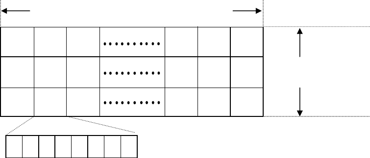
- 80 -
[Example] When xL + xH x 256 = 64
( xL+xH×256 )×8 dots = 512 dots
ド
ト
ドト
2 3 1 62 64 63
7 6 5 4 3 2 1 0
yL+yH×256 dots
128 127 126
68 67 65
K-1 K-2 K
MSB LSB
- 81 -
2.2.7 Status Commands
DLE EOT n
CT-S280 CT-S300 CT-S2000 CT-S4000 BD2-2220 CT-S310
support model PMU2XXX
[See Also]
[Caution] • Each status represents the current status. It is 1 byte data.
[Outline] [The specification which is common to the model]
[Range] 1≦n≦4
[Code] <10>H<04>H<n>
[Function] Sending status in real-time
DLE ENQ
• If another data string of <10>H<04>H<n> (1 n 4) is received, the printer acts the same way as
with this command. Therefore, the user should be reminded of this fact.
• This command can be executed even if printer setting by ESC = is invalid.
• If ASB (Automatic Status Back) is enabled by GS a, it is necessary to discriminate between the
status due to ASB and the status due to this command
• With parallel interface specifications, this command cannot be executed while the printer is in Busy
state.
• With serial interface specifications, this command is executed in offline state, receiving buffer full
state, and error state.
• This command is dealt with when it is received.
• This command is executed even if the printer is in offline state, receive-buffer full state, or error
state.
• The status is transferred without checking whether the host is ready to receive or busy.
Sends in real-time the status specified by “n”.
• The DLE EOT n command cannot be interleaved into the code string of another command
consisting of 2 bytes or more.
Appendix 5.3 “Identification of Send Status”
n Status
1 Printer status
2 Status caused by an offline condition
3 Status caused by an error
4 Continuous paper detector status
When memory SW1-3 is ON, the printer does not enter Busy state in the offline state and error
state.
Suppose a command “ESC * m nL nH [d1 ... dk]”, where d1 = <10>H, d2 = <04>H, d3 = <01>H.
[Example 1]
If the printer sends DLE EOT 3 after the host has sent up to ESC 3 in its attempt to send ESC 3 n,
the printer handles the ESC 3 as ESC 3 <10>H. Thus, the user should be cautious.
[Example 2]
、ESC c 4、GS a、GS r
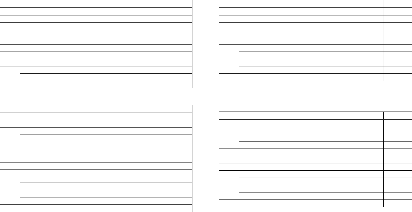
CT-S280
(1) Printer status (When n = 1 is specified) (3) Status caused by an error (when n = 3 is specified)
Bit Status Hex. Decimal Bit Status Hex. Decimal
0 Fixed 00 0 0 Fixed 00 0
1 Fixed 02 2 1 Fixed 02 2
2 Fixed 04 4 2 Fixed 00 0
Online status 00 0 3 Fixed 00 0
3 Offline status 08 8 4 Fixed 10 16
4 Fixed 10 16 Unrecoverable error not occurred 00 0
5
Not waiting online recovery 00 0 Unrecoverable error occurred 20 32
5 Waiting online recovery 20 32 Auto recovery error not occurred 00 0
6
FEED switch is not pressed 00 0 Auto recovery error occurred 40 64
6 FEED switch is pressed 40 64 7 Fixed 00 0
7 Fixed 00 0 Bit 6: If a head overheat error is detected, the printing is stopped until the
head temperature falls. At this time, bit 6 = 1.
(2) Status caused by an offline condition (When n = 2 is specified)
(4) Continuous paper detector status (When n = 4 is specified)
Bit Status Hex. Decimal
0 Unused 00 0 Bit Status Hex. Decimal
1 Unused 02 2 0 Fixed 00 0
Cover closed 00 0 1 Fixed 02 02
2 Cover open 04 4 Paper found by Paper Near-end Sensor 00 0
2
Not in paper feed state triggered by FEED
switch 00 0 Paper not found by Paper Near-end Sensor 04 4
3 Paper found by Paper Near-end Sensor 00 0
3
In paper feed state triggered by FEED switch 08 8 Paper not found by Paper Near-end Sensor 08 8
4 Unused 10 16 4 Fixed 10 16
Printing is not stopped because of “paper out”
state 00 0 Paper found by Paper-end Sensor 00 0
5
5 Paper not found by Paper-end Sensor 60 96
Printing is stopped because of “paper out” state 20 32 Paper found by Paper-end Sensor 00 0
6
Error not occurred 00 0 Paper not found by Paper-end Sensor 40 64
6 Error occurred 40 64 7 Fixed 00 0
7 Unused 00 0
Bit 5: Printing is stopped if the Paper-end detector detects a “paper out”
state, or if the printer is out of paper when the Paper Near-end
Sensor is enabled by ESC c 4. At this time, bit 5 = 1.
- 82 -

CT-S300/CT-S310
(1) Printer status (When n = 1 is specified) (3) Status caused by an error (when n = 3 is specified)
Bit Status Hex. Decimal Bit Status Hex. Decimal
0 Fixed 00 0 0 Fixed 00 0
1 Fixed 02 2 1 Fixed 02 2
No B.M detection error occurred
Status of pin 3 of drawer kick-out connector = L 00 0 00 0
2 (only when B.M paper is selected)
Status of pin 3 of drawer kick-out connector = H 04 4 2 A B.M detection error occurred
Online status 00 0 04 4
3 (only when B.M paper is selected)
Offline status 08 8 Auto cutter error not occurred 00 0
4 Fixed 10 16 3 Auto cutter error occurred 08 8
Not waiting online recovery 00 0
5 4 Fixed 10 16
Waiting online recovery 20 32 Unrecoverable error not occurred 00 0
FEED switch is not pressed 00 0 5
6 Unrecoverable error occurred 20 32
FEED switch is pressed 40 64 Auto recovery error not occurred 00 0
7 Fixed 00 0 6 Auto recovery error occurred 40 64
7 Fixed 00 0
(2) Status caused by an offline condition (When n = 2 is specified) Bit 3: If this error occurred because of a paper jam, for example, remove
the cause of the error, and then DLE ENQ n (1 n 2) can be used to
recover from the error. However, it is not possible to recover from
any error due to a circuit problem (e.g., broken wire).
Bit Status Hex. Decimal
0 Unused 00 0
1 Unused 02 2
Cover closed 00 0 Bit 6: If a head overheat error is detected, the printing is stopped until the
head temperature falls. At this time, bit 6 = 1.
2 Cover open 04 4
Not in paper feed state triggered by FEED
switch 00 0
3 (4) Continuous paper detector status (When n = 4 is specified)
In paper feed state triggered by FEED switch 08 8 Bit Status Hex. Decimal
4 Unused 10 16 0 Fixed 00 0
Printing is not stopped because of “paper out”
state 00 0 1 Fixed 02 02
5
Printing is stopped because of “paper out” state 20 32 Paper found by Paper Near-end Sensor 00 0
2 Paper not found by Paper Near-end Sensor
Error not occurred 00 0 04 4
6 Error occurred 40 64 Paper found by Paper Near-end Sensor 00 0
3
7 Unused 00 0 Paper not found by Paper Near-end Sensor 08 8
4 Fixed 10 16
Bit 5: Printing is stopped if the Paper-end detector detects a “paper out”
state, or if the printer is out of paper when the Paper Near-end
Sensor is enabled by ESC c 4. At this time, bit 5 = 1.
Paper found by Paper-end Sensor 00 0
5 Paper not found by Paper-end Sensor 60 96
Paper found by Paper-end Sensor 00 0
6
Paper not found by Paper-end Sensor 40 64
7 Fixed 00 0
- 83 -
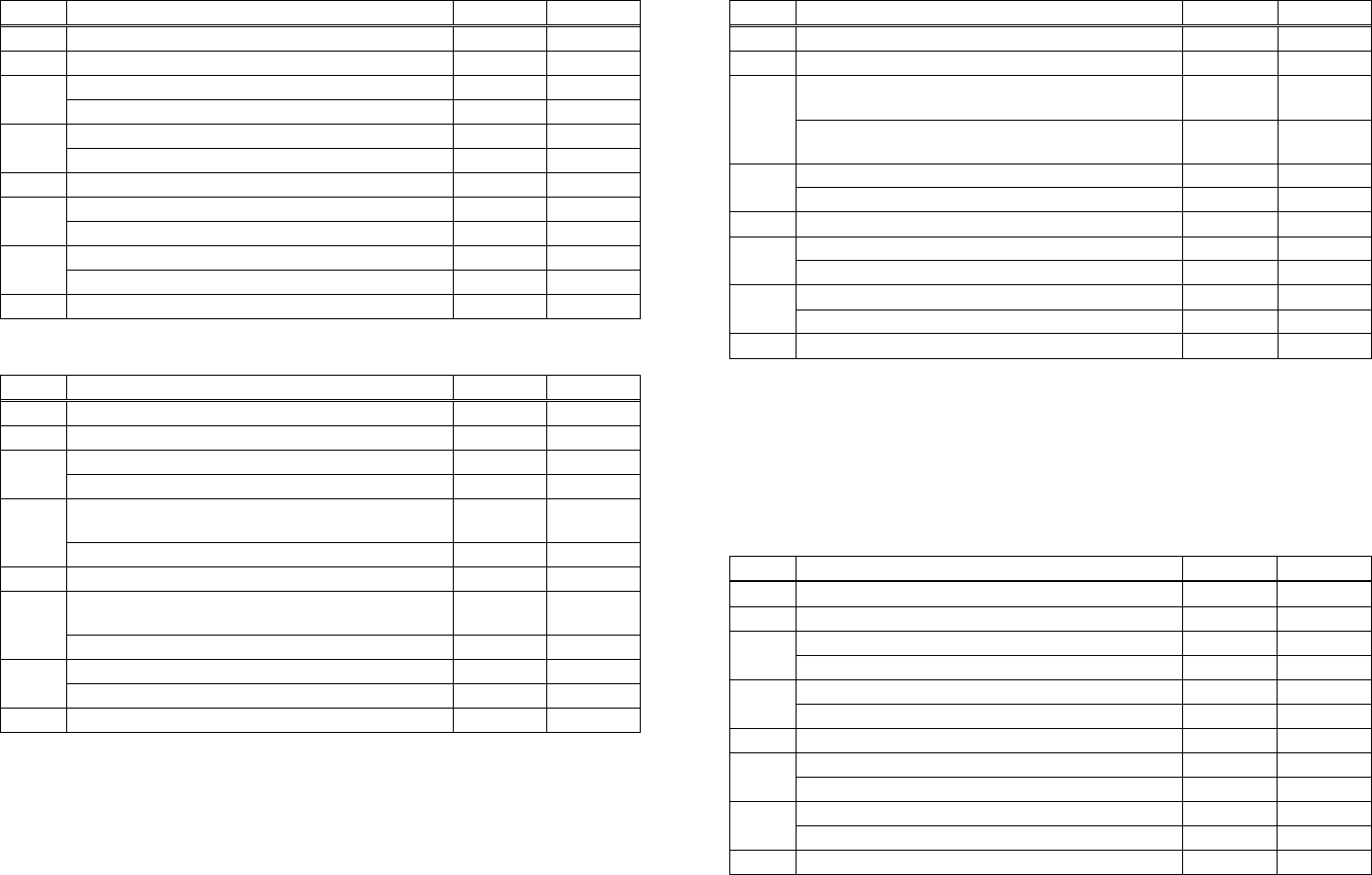
CT-S2000
(1) Printer status (When n = 1 is specified) (3) Status caused by an error (when n = 3 is specified)
Bit Status Hex. Decimal Bit Status Hex. Decimal
0 Fixed 00 0 0 Fixed 00 0
1 Fixed 02 2 1 Fixed 02 2
Status of pin 3 of drawer kick-out connector = L 00 0 No B.M detection error occurred 00 0
2 (only when B.M paper is selected)
Status of pin 3 of drawer kick-out connector = H 04 4 2 A B.M detection error occurred
Online status 00 0 04 4
3 (only when B.M paper is selected)
Offline status 08 8 Auto cutter error not occurred 00 0
4 Fixed 10 16 3 Auto cutter error occurred 08 8
Not waiting online recovery 00 0
5 4 Fixed 10 16
Waiting online recovery 20 32 Unrecoverable error not occurred 00 0
FEED switch is not pressed 00 0 5
6 Unrecoverable error occurred 20 32
FEED switch is pressed 40 64 Auto recovery error not occurred 00 0
7 Fixed 00 0 6 Auto recovery error occurred 40 64
7 Fixed 00 0
(2) Status caused by an offline condition (When n = 2 is specified) Bit 3: If this error occurred because of a paper jam, for example, remove
the cause of the error, and then DLE ENQ n (1 n 2) can be used to
recover from the error. However, it is not possible to recover from
any error due to a circuit problem (e.g., broken wire).
Bit Status Hex. Decimal
0 Unused 00 0
1 Unused 02 2
Cover closed 00 0 Bit 6: If a head overheat error is detected, the printing is stopped until the
head temperature falls. At this time, bit 6 = 1.
2 Cover open 04 4
Not in paper feed state triggered by FEED
switch 00 0
3 (4) Continuous paper detector status (When n = 4 is specified)
In paper feed state triggered by FEED switch 08 8 Bit Status Hex. Decimal
4 Unused 10 16 0 Fixed 00 0
Printing is not stopped because of “paper out”
state 00 0 1 Fixed 02 02
5
Paper found by Paper Near-end Sensor 00 0
Printing is stopped because of “paper out” state 20 32 2 Paper not found by Paper Near-end Sensor 04 4
Error not occurred 00 0
6 Paper found by Paper Near-end Sensor 00 0
Error occurred 40 64 3 Paper not found by Paper Near-end Sensor 08 8
7 Unused 00 0
4 Fixed 10 16
Bit 5: Printing is stopped if the Paper-end detector detects a “paper out”
state, or if the printer is out of paper when the Paper Near-end
Sensor is enabled by ESC c 4. At this time, bit 5 = 1.
Paper found by Paper-end Sensor 00 0
5 Paper not found by Paper-end Sensor 60 96
Paper found by Paper-end Sensor 00 0
6
Paper not found by Paper-end Sensor 40 64
7 Fixed 00 0
- 84 -

CT-S4000
(1) Printer status (When n = 1 is specified) (3) Status caused by an error (when n = 3 is specified)
Bit Status Hex. Decimal Bit Status Hex. Decimal
0 Fixed 00 0 0 Fixed 00 0
1 Fixed 02 2 1 Fixed 02 2
Status of pin 3 of drawer kick-out connector = L 00 0 No B.M detection error occurred 00 0
2 (only when B.M paper is selected)
Status of pin 3 of drawer kick-out connector = H 04 4 2 A B.M detection error occurred
Online status 00 0 04 4
3 (only when B.M paper is selected)
Offline status 08 8 Auto cutter error not occurred 00 0
4 Fixed 10 16 3 Auto cutter error occurred 08 8
Not waiting online recovery 00 0
5 4 Fixed 10 16
Waiting online recovery 20 32 Unrecoverable error not occurred 00 0
FEED switch is not pressed 00 0 5
6 Unrecoverable error occurred 20 32
FEED switch is pressed 40 64 Auto recovery error not occurred 00 0
7 Fixed 00 0 6 Auto recovery error occurred 40 64
7 Fixed 00 0
(2) Status caused by an offline condition (When n = 2 is specified) Bit 3: If this error occurred because of a paper jam, for example, remove
the cause of the error, and then DLE ENQ n (1 n 2) can be used to
recover from the error. However, it is not possible to recover from
any error due to a circuit problem (e.g., broken wire).
Bit Status Hex. Decimal
0 Unused 00 0
1 Unused 02 2
Cover closed 00 0 Bit 6: If a head overheat error is detected, the printing is stopped until the
head temperature falls. At this time, bit 6 = 1.
2 Cover open 04 4
Not in paper feed state triggered by FEED
switch 00 0
3 (4) Continuous paper detector status (When n = 4 is specified)
In paper feed state triggered by FEED switch 08 8 Bit Status Hex. Decimal
4 Unused 10 16 0 Fixed 00 0
Printing is not stopped because of “paper out”
state 00 0 1 Fixed 02 02
5
Paper found by Paper Near-end Sensor 00 0
Printing is stopped because of “paper out” state 20 32 2 Paper not found by Paper Near-end Sensor 04 4
Error not occurred 00 0
6 Paper found by Paper Near-end Sensor 00 0
Error occurred 40 64 3 Paper not found by Paper Near-end Sensor 08 8
7 Unused 00 0
4 Fixed 10 16
Bit 5: Printing is stopped if the Paper-end detector detects a “paper out”
state, or if the printer is out of paper when the Paper Near-end
Sensor is enabled by ESC c 4. At this time, bit 5 = 1.
Paper found by Paper-end Sensor 00 0
5 Paper not found by Paper-end Sensor 60 96
Paper found by Paper-end Sensor 00 0
6
Paper not found by Paper-end Sensor 40 64
7 Fixed 00 0
- 85 -
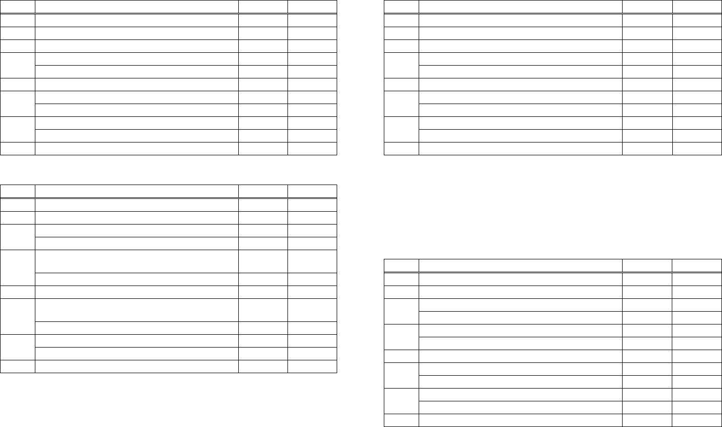
BD2-2220
(1) Printer status (When n = 1 is specified) (3) Status caused by an error (when n = 3 is specified)
Bit Status Hex. Decimal Bit Status Hex. Decimal
0 Fixed 00 0 0 Fixed 00 0
1 Fixed 02 2 1 Fixed 02 2
2 Fixed 04 4 2 Fixed 00 0
Online status 00 0 Auto cutter error not occurred 00 0
3 3
Offline status 08 8 Auto cutter error occurred 08 8
4 Fixed 10 16 4 Fixed 10 16
Not waiting online recovery 00 0 Unrecoverable error not occurred 00 0
5 5
Waiting online recovery 20 32 Unrecoverable error occurred 20 32
LF-SW signal is High-Level 00 0 Auto recovery error not occurred 00 0
6 6
LF-SW signal is Low-Level 40 64 Auto recovery error occurred 40 64
7 Fixed 00 0 7 Fixed 00 0
Bit 3: If this error occurred because of a paper jam, for example, remove the
cause of the error, and then DLE ENQ n (1 n 2) can be used to
recover from the error. However, it is not possible to recover from
any error due to a circuit problem (e.g., broken wire).
(2) Status caused by an offline condition (When n = 2 is specified)
Bit Status Hex. Decimal
0 Unused 00 0
1 Unused 02 2
Head-down 00 0
Bit 6: If a head overheat error is detected, the printing is stopped until the
head temperature falls. At this time, bit 6 = 1.
2 Head-up 04 4
(4) Continuous paper detector status (When n = 4 is specified)
Not in paper feed state triggered by LF-SW
signal 00 0 Bit Status Hex. Decimal
3
In paper feed state triggered by LF-SW signal 08 8 0 Fixed 00 0
4 Unused 10 16 1 Fixed 02 02
Printing is not stopped because of “paper out”
state 00 0 Paper found by Paper Near-end Sensor 00 0
2
5 Paper not found by Paper Near-end Sensor 04 4
Printing is stopped because of “paper out” state 20 32 Paper found by Paper Near-end Sensor 00 0
3
Error not occurred 00 0 Paper not found by Paper Near-end Sensor 08 8
6 Error occurred 40 64 4 Fixed 10 16
7 Unused 00 0 Paper found by Paper-end Sensor 00 0
5
Bit 5: Printing is stopped if the Paper-end detector detects a “paper out”
state, or if the printer is out of paper when the Paper Near-end
Sensor is enabled by ESC c 4. At this time, bit 5 = 1.
Paper not found by Paper-end Sensor 60 96
Paper found by Paper-end Sensor 00 0
6 Paper not found by Paper-end Sensor 40 64
7 Fixed 00 0
- 86 -

Hex. Decimal
- 87 -
PMU2XXX
(1) Printer status (When n = 1 is specified)
Bit Status Hex. Decimal
0 Fixed 00 0
1 Fixed 02 2
2 Fixed 04 4
Online status 00 0
3 Offline status 08 8
4 Fixed 10 16
Not waiting online recovery 00 0
5 Waiting online recovery 20 32
LF-SW signal is High-Level 00 0
6 LF-SW signal is Low-Level 40 64
7 Fixed 00 0
(2) Status caused by an offline condition (When n = 2 is specified)
Bit Status Hex. Decimal
0 Unused 00 0
1 Unused 02 2
Head-down 00 0
2 Head-up 04 4
Not in paper feed state triggered by LF-SW
signal 00 0
3
In paper feed state triggered by LF-SW signal 08 8
4 Unused 10 16
Printing is not stopped because of “paper out”
state 00 0
5
Printing is stopped because of “paper out” state 20 32
Error not occurred 00 0
6 Error occurred 40 64
7 Unused 00 0
Bit 5: Printing is stopped if the Paper-end detector detects a “paper out”
state, or if the printer is out of paper when the Paper Near-end
Sensor is enabled by ESC c 4. At this time, bit 5 = 1.
(3) Status caused by an error (when n = 3 is specified)
Bit Status Hex. Decimal
0 Fixed 00 0
1 Fixed 02 2
No B.M detection error occurred
(only when B.M paper is selected) 00 0
2 A B.M detection error occurred
(only when B.M paper is selected) 04 4
Auto cutter error not occurred 00 0
3 Auto cutter error occurred 08 8
4 Fixed 10 16
Unrecoverable error not occurred 00 0
5 Unrecoverable error occurred 20 32
Auto recovery error not occurred 00 0
6 Auto recovery error occurred 40 64
7 Fixed 00 0
Bit 3: If this error occurred because of a paper jam, for example, remove the
cause of the error, and then DLE ENQ n (1 n 2) can be used to
recover from the error. However, it is not possible to recover from
any error due to a circuit problem (e.g., broken wire).
Bit 6: If a head overheat error is detected, the printing is stopped until the
head temperature falls. At this time, bit 6 = 1.
(4) Continuous paper detector status (When n = 4 is specified)
Bit Status
0 Fixed 00 0
1 Fixed 02 02
Paper found by Paper Near-end Sensor 00 0
2 Paper not found by Paper Near-end Sensor 04 4
Paper found by Paper Near-end Sensor 00 0
3 Paper not found by Paper Near-end Sensor 08 8
4 Fixed 10 16
Paper found by Paper-end Sensor 00 0
5 Paper not found by Paper-end Sensor 60 96
Paper found by Paper-end Sensor 00 0
6 Paper not found by Paper-end Sensor 40 64
00 0 7 Fixed
- 88 -
ESC u n
CT-S280 CT-S300 CT-S2000 CT-S4000 BD2-2220 CT-S310
support model PMU2XXX
[Function] Sending the peripheral device status
[Code] <1B>H<75>H<n>
[Outline] [The specification which is common to the model]
Send the current drawer kick connector pin#3 status.
• n has the type shown in the table below:
n Connector Pin
Drawer kick connector pin#3
0
[Caution] • Status to be sent uses 1 byte that has the value listed in the table below.
• DTR/DSR control sends 1 byte only after checking that host is ready to receive (DSR signal: space
status). For XON/XOFF control, 1 byte is sent without checking DSR signal status.
• For DTR/DSR, if host is not ready to receive (DSR signal: mark status), it waits for ready condition
to receive.
• Paper-end status causes BUSY status, thus this command may be in the receive-not-ready status.
• This command is valid only when MSW3-7 is set to ON.
Value
Bit Function 0 1
Pin #3 level
0 ‘L’ ‘H’
Undefined
1 ―― ――
Undefined
2 ―― ――
――
Undefined
3 ――
Unused
4 0: Fixed ――
Undefined
5 ―― ――
Undefined
6 ―― ――
Undefined
7 ―― ――
[Sample Program]
OPEN "COM1:N81NN" AS #1 → OPEN statement depends on types of BASIC.
PRINT #1,CHR$(&H1B);"u";CHR$(0)
A$ = INPUT$(1, #1)
CLOSE #1
- 89 -
ESC v
CT-S280 CT-S300 CT-S2000 CT-S4000 BD2-2220 CT-S310
support model PMU2XXX
[Function] Transmission of printer status
[Code] <1D>H<76>H
[Outline] [The specification which is common to the model]
Transmits current printer status.
[Caution] • Status is transmitted in 1byte with the content shown in the following table.
• In case of DTR/DSR control, only 1byte is transmitted after making sure the host is ready for
reception (DSR signal is in the Space state). In case of XON/XOFF control, only 1byte is
transmitted without checking the status of DSR signal.
• In case of DTR/DSR, if the host is not ready for reception (DSR signal in Mark state, wait till
reception is available.
• Paper-end status causes BUSY status, thus this command may be in the receive-not-ready status.
• This command is valid only when MSW3-7 is set to ON.
Value
Bit Position 0 1
0 Paper Near-end With paper No paper
1 Undefined ―― ――
2 Paper-end With paper No paper
――
3 Undefined ――
4 Unused Fixed ――
5 Undefined ―― ――
6 Undefined ―― ――
7 Undefined ―― ――
Bit 2: In case of Paper End, as this printer goes offline, this command is not
executed. Therefore, status "No Paper (04H)" is never transmitted.
[Sample Program]
OPEN "COM1:N81NN" AS #1 → OPEN statement varies with the type of BASIC.
PRINT #1, CHR$(&H1B);"v";
A$ = INPUT$(1, #1)
CLOSE #1
- 90 -
GS a n
CT-S280 CT-S300 CT-S2000 CT-S4000 BD2-2220 CT-S310
support model PMU2XXX
[Function] Enabling/disabling ASB (Automatic Status Back)
[Code] <1D>H<61>H<n>
[Range] 0≦n≦255
[Outline] [The specification which is common to the model]
This command selects the status item to be addressed by ASB (Automatic Status Back.)
Bit Status Item Addressed by ASB Hex. Decimal
Status of pin 3 of drawer kick-out connector = Disabled 00 0
0 Status of pin 3 of drawer kick-out connector = Enabled 01 1
Online/offline status = Disabled 00 0
1 Online/offline status = Enabled 02 2
Error status = Disabled 00 0
2 Error status = Enabled 04 4
Continuous Paper Sensor = Disabled 00 0
3 Continuous Paper Sensor = Enabled 08 8
- -
4 Undefined
- -
5 Undefined
- -
6 Undefined
- -
7 Undefined
[Caution] [The specification which is common to the model]
• If any status item is enabled, the status is sent to the host when this command is executed. After
that time on, the status is sent each time an enabled status item changes. Because each status
item represents the current condition, status items disabled for ASB may also have changed.
• The ASB function is disabled if all status items are disabled.
• If the ASB function is enabled by default, the host receives the status the first time the printer gets
ready for communication after it is turned on.
• The printer sends 4 bytes of status shown in the tables below, without checking whether the host
is ready to receive or busy. The 4 bytes of status is a continuous string except for XOFF code.
• Because this command is executed when data is mapped in the receive buffer, there may be a
delay between command receiving and status sending depending on the condition of the receive
buffer.
• Even if the printer is excluded from the selection of peripheral equipment ESC =, the 4 bytes of
status is sent to the host whenever status changes.
• When DLE EOT, GS I, or GS r is used, the host must discriminate between the status specified by
these commands and the status due to ASB.
[The specification which depend on the model]
CT-S280/BD2-2220/PMU2XXX
• Bit 2 of the first byte (printer information) of the status sent in 4 bytes is set to 00h
because drawer is not supported.
- 91 -
(1) 1st byte (Printer information)
Bit Status Hex. Decimal
0 Unused 00 0
1 Unused 00 0
Status of pin 3 of drawer kick-out connector = “L” 00 0
2 Status of pin 3 of drawer kick-out connector = “H” 04 4
Online status 00 0
3 Offline status 08 8
4 Unused 01 16
Cover closed 00 0
5 Cover open 20 32
Not in paper feed state triggered by FEED switch 00 0
6 In paper feed state triggered by FEED switch 40 64
7 Unused 00 0
(2) 2nd byte (Error occurrence information)
Bit Status Hex. Decimal
0 Undefined - -
1 Undefined - -
No Mechanism error and B.M detection error occurred.
(only when B.M paper is selected) 00 0
2 A Mechanism error or B.M detection error occurred.
(only when B.M paper is selected) 04 4
Auto cutter error not occurred 00 0
3 Auto cutter error occurred 08 8
4 Unused 00 0
Unrecoverable error not occurred 00 0
5 Unrecoverable error occurred 20 32
Auto recovery error not occurred 00 0
6 Auto recovery error occurred 40 64
7 Unused 00 0
*Bit 2: It usually occurs by a cover open error (when printer is printing).
In the case of a model for BM/ label, it occurs at the time of a BM/ label detection error.
(3) 3rd byte (Paper Sensor information)
Bit Status Hex. Decimal
Paper found by Paper Near-end Sensor 00 0
0,1 Paper not found by Paper Near-end Sensor 03 3
Paper found by Paper-end Sensor 00 0
2,3 Paper not found by Paper-end Sensor 0C 12
4 Unused 00 0
5 Undefined - -
6 Undefined - -
7 Unused 00 0
- 92 -
(4) 4th byte (Paper Sensor information)
In case of MSW3-7 ON
Bit Status Hex. Decimal
0 Undefined - -
1 Undefined - -
2 Undefined - -
3 Undefined - -
4 Unused 00 0
5 Undefined - -
6 Undefined - -
7 Unused 00 0
In case of MSW3-7 OFF (CBM1000 non-compatible mode)
Bit Status Hex. Decimal
0 Reserved 01 1
1 Reserved 02 2
2 Reserved 04 4
3 Reserved 08 8
4 Fixed 00 0
5 Reserved 00 00
6 Reserved 00 00
7 Fixed 00 0
[Default] When MSW 1-3 OFF: n = 0
When MSW 1-3 ON: n = 2
[See Also] DLE EOT、GS r
- 93 -
GS r n
CT-S280 CT-S300 CT-S2000 CT-S4000 BD2-2220 CT-S310
support model PMU2XXX
[Function] Sending status
[Code] <1D>H<72>H<n>
[Range] CT-S280/BD2-2220/PMU2XXX
n=1、49
CT-S300/CT-S2000/CT-S4000/CT-S310
1≦n≦2、49≦n≦50
[Outline] [The specification which is common to the model]
Sends the specified status to the host.
n Function
1,49 Sends the Paper Sensor status.
2,50 Sends the Drawer Kick-out Connector status.
[Caution] [The specification which is common to the model]
• When the serial interface is used:
For DTR/DSR control:
The printer sends the status after verifying that the host is ready to receive. If the host is not
ready to receive, the printer waits for the host to become ready to receive.
For XON/XOFF control:
The printer sends the status without checking whether the host is ready to receive or busy.
• Because this command is executed when data is mapped in the receive buffer, there may be a
delay between receiving the command and sending the status depending on the condition of the
receive buffer.
• If ASB (Automatic Status Back) is enabled by GS a, the host must discriminate between the status
due to this command and the status due to ASB.
• Whenever the Paper-end Sensor detects a “paper out” state, the printer goes offline, and the
command is not executed. Therefore, the printer never sends a status “No paper in Paper-end
detector (0CH)”.
[The specification which depend on the model]
CT-S280/BD2-2220/ PMU2XXX
• At the setting of MSW3-7 OFF, paper sensor status is fixed to 00h.
- 94 -
• Paper Sensor status (n = 1, 49)
Bit Status Hex. Decimal
Paper found by Paper Near-end Sensor 00 0
0,1 Paper not found by Paper Near-end Sensor 03 3
Paper found by Paper-end Sensor 00 0
2,3 Paper not found by Paper-end Sensor (0C) (12)
4 Unused 00 0
5 Undefined - -
6 Undefined - -
7 Unused 00 0
• Drawer kick-out connector status (n = 2, 50)
Bit Status Hex. Decimal
Status of pin 3 of drawer kick connector = “L” 00 0
0 Status of pin 3 of drawer kick connector = “H” 01 1
1 Undefined ― ―
2 Undefined ― ―
3 Undefined ― ―
4 Unused 00 0
5 Undefined ― ―
6 Undefined ― ―
7 Unused 00 0
[See Also] Appendix 5.3 “Identification of Send Status”
DLE EOT、GS a

- 95 -
2.2.8 Paper Detecting Commands
ESC c 3 n
CT-S280 CT-S300 CT-S2000 CT-S4000 BD2-2220 CT-S310
support model PMU2XXX
[Function] Selecting the Paper Sensor valid for a Paper-end signal output
[Code] <1B>H<63>H<33>H<n>
[Range] 0≦n≦255
[Outline] [The specification which is common to the model]
This command selects by which Paper Sensor a Paper-end signal should be output. Each bit for “n”
has the following meaning:
Value
Bit Position 0 1
0 Paper Near-end Disabled Enabled
1 Paper Near-end Disabled Enabled
2 Paper-end Disabled Enabled
3 Paper-end Disabled Enabled
4 Undefined — —
5 Undefined — —
6 Undefined — —
7 Undefined — —
[Caution] This command is valid only for the parallel interface.
[Default] n=15
- 96 -
ESC c 4 n
CT-S280 CT-S300 CT-S2000 CT-S4000 BD2-2220 CT-S310
support model PMU2XXX
[Function] Selecting the Paper Near-end Sensor valid for print stop
[Code] <1B>H<63>H<34>H<n>
[Range] 0≦n≦255
[Outline] [The specification which is common to the model]
This command selects the Paper Near-end Sensor which helps to stop printing when the paper
supply almost runs out.
Each bit for “n” has the following meaning:
Value
Bit Position 0 1
0 Paper Near-end Disabled Enabled
1 Paper Near-end Disabled Enabled
2 Undefined ―― ――
3 Undefined ―― ――
4 Undefined ―― ――
5 Undefined ―― ――
6 Undefined ―― ――
7 Undefined ―― ――
[Caution] This printer can only select one kind of Paper Sensor, a Paper Near-end Sensor.
[Default] n=0
- 97 -
2.2.9 Panel Switch Commands
ESC c 5 n
CT-S280 CT-S300 CT-S2000 CT-S4000 BD2-2220 CT-S310
support model PMU2XXX
[Function] Enabling/disabling the panel switches
[Code] <1B>H<63>H<35>H<n>
[Range] 0≦n≦255
[Outline] [The specification which is common to the model]
Enabling/disabling the FEED switch.
• “n” is valid only for the lowest bit (n0).
• Control by the lowest bit (n0) is shown as follows:
n0 Condition
0 FEED switch (LF-SW signal) valid
1 FEED switch (LF-SW signal) invalid
[Caution] • When the FEED switch is disabled with this command, the paper cannot be fed by operating the
FEED switch.
• While switch operation is waited at the execution of macro, the FEED switch is always enabled
regardless of the setting of this command but no paper feed operation is carried out.
[Default] n=0
[Sample Program]
LPRINT CHR$(&H1B);"c5";CHR$(0); ・・・・・ When enabling the FEED switch
LPRINT CHR$(&H1B);"c5";CHR$(1); ・・・・・ When disabling the FEED switch

- 98 -
2.2.10 Macro Commands
GS :
CT-S280 CT-S300 CT-S2000 CT-S4000 BD2-2220 CT-S310
support model PMU2XXX
[Function] Starting/ending macro definition
[Code] <1D>H<3A>H
[Outline] [The specification which is common to the model]
Specifying starting/ending macro definition.
Reception of this command during macro definition signifies ending the macro definition.
[Caution] • Maximum content available for macro definition is 2048 bytes. A portion exceeding 2048 bytes is
not defined.
• When GS ^ is processed in macro definition, the macro definition is stopped and the content of
definition is cleared.
• Even with ESC @ (Initialization of the printer) having been executed, defined content is not
cleared. Therefore, it is possible to include ESC @ into the content of macro definition.
• Normal printing operation is carried out even during macro definition.
[Default] The initial value is not defined.
[See Also] GS ^
[Sample Program] [Print Results]
LPRINT CHR$(&H1D);":"; +------+
Normal printing during macro definition
Printing during macro execution
LPRINT "+------+";CHR$(&HA); | |
LPRINT "| |"; CHR$(&HA); +------+
LPRINT "+------+"; CHR$(&HA); +------+
LPRINT CHR$(&H1D);":"; | |
LPRINT CHR$(&H1D);"^"; +------+
LPRINT CHR$(2); CHR$(10); +------+
| |
+------+

- 99 -
GS ^ n1 n2 n3
CT-S280 CT-S300 CT-S2000 CT-S4000 BD2-2220 CT-S310
support model PMU2XXX
[Function] Executing the macro
[Code] <1D>H<5E>H<n1><n2><n3>
[Range] 0≦n1≦255
0≦n2≦255
0≦n3≦1
[Outline] [The specification which is common to the model]
Executing contents defined in macro.
n1 : The number of times of macro execution
n2 : Waiting time on macro execution: Waiting time of n2 x 100 msec is given for every execution.
n3 : Macro execution mode
n3 = 0 Continuous execution: The Macro is executed “n1” times continuously at the time
interval specified by “n2”.
n3 = 1 Execution by FEED Switch: After waiting for the time specified by “n2”, the ARARM LED
flickers and the FEED switch is waiting to be pressed. When
it is pressed, the macro is executed once. This action is
repeated “n1” times.
[Caution] • When this command is received while in macro definition, suspension of macro definition is
indicated. At this time, the defined content is cleared.
• No execution takes place when the macro is held undefined.
• While in macro execution with n3 = 1, paper feed with the FEED switch is not available.
[See Also] GS :
[Sample Program]
Refer to Sample Program and Print Results for GS:.
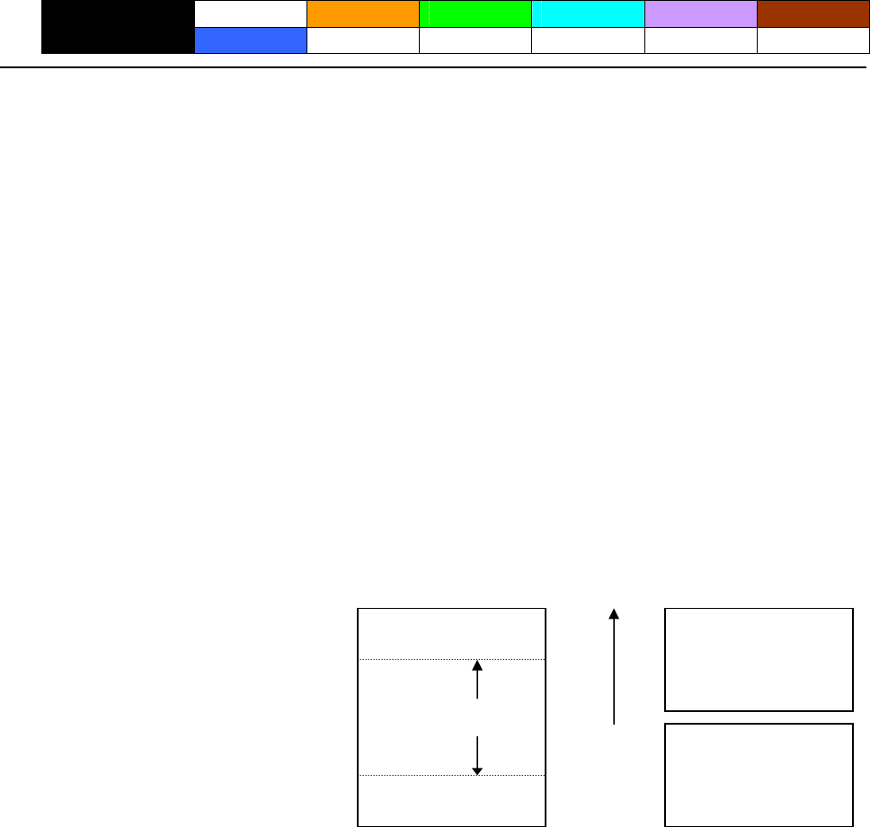
- 100 -
2.2.11 Cutter Commands
ESC i
CT-S280 CT-S300 CT-S2000 CT-S4000 BD2-2220 CT-S310
support model PMU2XXX
[Function] Full cutting of paper
[Code] <1B>H<69>H
[Outline] [The specification which is common to the model]
Executes full cutting of paper.
[Caution] [The specification which is common to the model]
• This command only works it is entered at the beginning of a line.
• Before cutting paper, feed the paper more than the cutting position of paper from the print
position. Without this paper feeding, the character just after printing remains before the cutter.
[The specification which depend on the model]
CT-S300/CT-S2000/CT-S4000/CT-S310/PMU2XXX
• With label- or BM-supported model, this command does not function at the setting of BM
paper/label paper setting.
[Sample Program] [Print Results]
Cut state
LPRINT “AAAAA”;
AAAAA
Cut position
AAAAA Paper feed
direction
LPRINT CHR$(&H1B);"J";
LPRINT CHR$(150);
LPRINT CHR$(&H1B);"i";
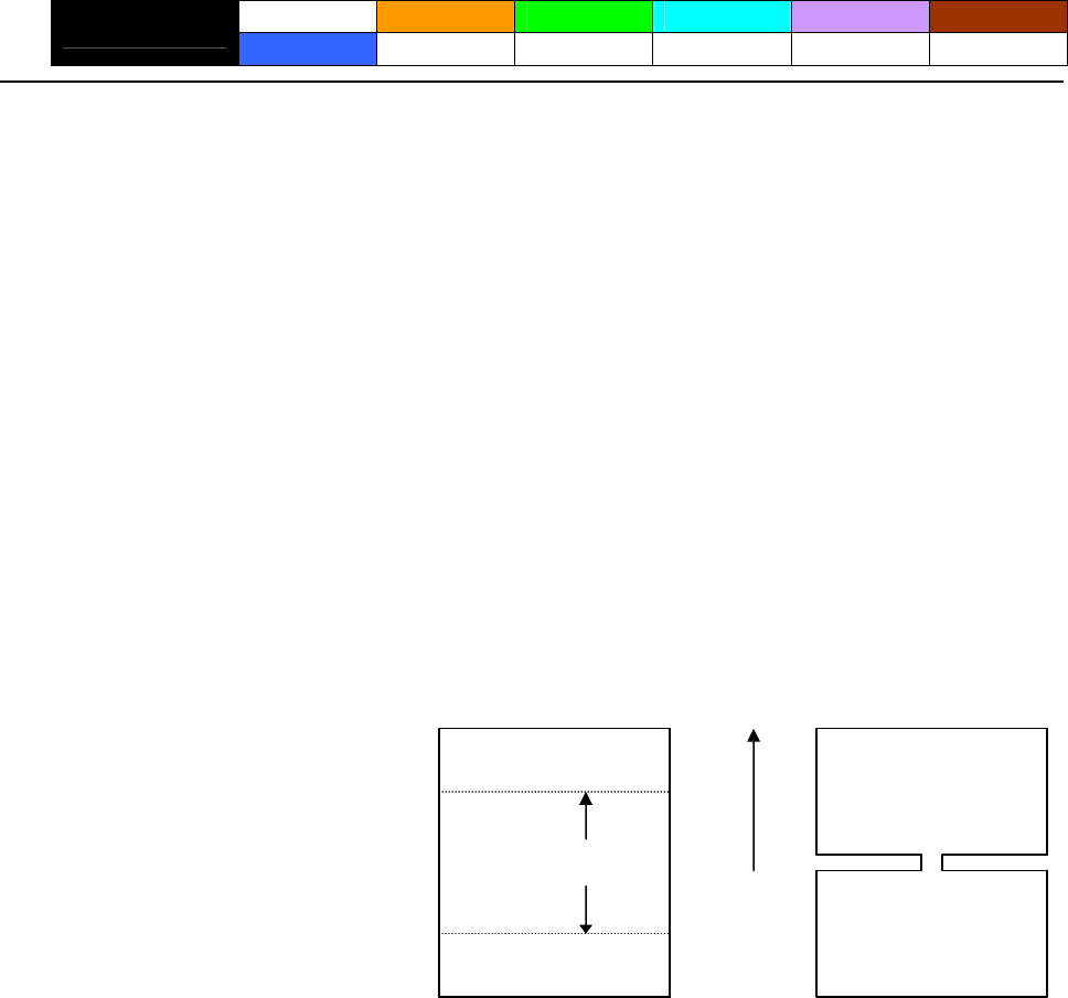
- 101 -
ESC m
CT-S280 CT-S300 CT-S2000 CT-S4000 BD2-2220 CT-S310
support model PMU2XXX
[Function] Partial cutting of paper
[Code] <1B>H<6D>H
[Outline] [The specification which is common to the model]
Executes partial cutting of paper.
[Caution] [The specification which is common to the model]
• This command only works it is entered at the beginning of a line.
• Before cutting paper, feed the paper more than the cutting position of paper from the print
position. Without this paper feeding, the character just after printing remains before the cutter.
[The specification which depend on the model]
CT-S300/CT-S2000/CT-S4000/CT-S310/PMU2XXX
• With label- or BM-supported model, this command does not function at the setting of BM
paper/label paper setting.
[Sample Program] [Print Results]
Cut state
AAAAA
Cut position
AAAAA Paper feed
direction
LPRINT “AAAAA”;
LPRINT CHR$(&H1B);"J";
LPRINT CHR$(150);
LPRINT CHR$(&H1B);"m";
- 102 -
GS V m ・・・ (1)
GS V m n ・・・ (2)
CT-S280 CT-S300 CT-S2000 CT-S4000 BD2-2220 CT-S310
support model PMU2XXX
[Function] Cutting the paper
[Code] (1)<1D>H<56>H<m>
(2)<1D>H<56>H<m><n>
[Range] (1)0≦m≦1、48≦m≦49
(2)m=65、66
0≦n≦255
[Outline] [The specification which is common to the model]
Performs the specified paper cutting.
m Function
0,48 Full cut
1,49 Partial cut (Leaving a bridge area uncut)
Paper feed by “cut position + {n×basic calculation pitch}” and full cut
65
Paper feed by “cut position + {n×basic calculation pitch}” and partial cut
66
[Caution] [The specification which is common to the model]
• In STANDARD MODE, this command only works when it is entered at the beginning of a line.
• Control to make the length of cut paper less than 10 mm is not executed.
For (1):
• Executes cutting of paper.
For (2):
• If n = 0, the paper is fed to the cut position, and then cut. If n ≠0, the paper is fed by “n x
basic calculation pitch” inches past the cut position, and then cut.
• The basic calculation pitch is set by GS P. The paper feed amount is calculated with the vertical
basic calculation pitch (y). A fraction resulting from the calculation is corrected with the
minimum pitch of the mechanism, and the remainder is omitted.
[The specification which depend on the model]
CT-S300/CT-S2000/CT-S4000/CT-S310/PMU2XXX
• With label- or BM-supported model, this command does not function at the setting of BM
paper/label paper setting.
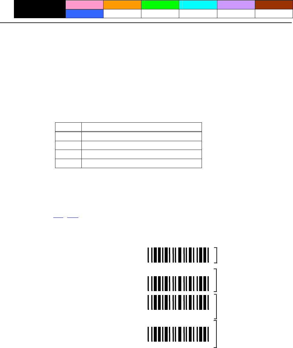
- 103 -
2.2.12 Bar Code Commands
GS H n
CT-S280 CT-S300 CT-S2000 CT-S4000 BD2-2220 CT-S310
support model PMU2XXX
[Function] Selecting of printing position of HRI characters
[Code] <1D>H<48>H<n>
[Range] 0≦n≦3、48≦n≦51
[Outline] [The specification which is common to the model]
Selecting printing position of HRI characters in printing bar codes.
“n” means the followings.
Printing Position n
0,48 No printing
1,49 Above the bar code
2,50 Below the bar code
3,51 Both above and below the bar code
The HRI characters refer to the bar code-turned characters so that you can read them.
[Default] n=0
[See Also] GS f、GS k
[Sample Program] [Print Results]
*12*
*12*
*12*
*12*
No HRI characters
Printed above
Printed below
Printed above and below
LPRINT CHR$(&H1B);”3”; CHR$(5);
LPRINT CHR$(&H1D);”h”; CHR$(50);
LPRINT CHR$(&H1D);”H”; CHR$(0);
GOSUB BC
LPRINT CHR$(&H1D);”H”; CHR$(1);
GOSUB BC
LPRINT CHR$(&H1D);”H”; CHR$(2);
GOSUB BC
LPRINT CHR$(&H1D);”H”; CHR$(3);
GOSUB BC
END
BC:
LPRINT CHR$(&H1D);”k”;
LPRINT CHR$(4);
LPRINT “12”; CHR$(0);
LPRINT CHR$(&HA);
RETURN

- 104 -
GS f n
CT-S280 CT-S300 CT-S2000 CT-S4000 BD2-2220 CT-S310
support model PMU2XXX
[Function] Selecting the font of HRI characters
[Code] <1D>H<66>H<n>
[Range] 0≦n≦2、48≦n≦50
[Outline] [The specification which is common to the model]
Selecting the font of HRI characters in printing bar code.
The type of font can be selected with “n” as follows:・
[The specification which depend on the model]
CT-S300/CT-S310
n Font
Font A (12×24)
0,48
Font B (9 ×17)
1,49
Font C (8×16)
2,50
CT-S280/CT-S2000/CT-S4000/BD2-2220/PMU2XXX
Font n
Font A (12×24)
0,48
Font B (9×24)
1,49
Font C (8×16)
2,50
[Caution] The HRI characters are printed at the position specified with GS H.
[Default] n=0
[See Also] GS H
[Sample Program] [Print Results]
LPRINT CHR$(&H1D);"h"; CHR$(50);
* 1 2 *
* 1 2 * FONT A
FONT B
LPRINT CHR$(&H1D);"H"; CHR$(2);
LPRINT CHR$(&H1D);"f"; CHR$(0);
GOSUB BC
LPRINT CHR$(&H1D);"f"; CHR$(1);
GOSUB BC
END
BC:
LPRINT CHR$(&H1D);"k";
LPRINT CHR$(4);
LPRINT “12”; +CHR$(0);
LPRINT CHR$(&HA);
RETURN

- 105 -
GS h n
CT-S280 CT-S300 CT-S2000 CT-S4000 BD2-2220 CT-S310
support model PMU2XXX
[Function] Specifying the height of the bar code
[Code] <1D>H<68>H<n>
[Range] 1≦n≦255
[Outline] [The specification which is common to the model]
Selecting bar code height.
“n” denotes the number of dots in the vertical direction.
[Sample Program]
Refer to Sample Program and Print Results for GS w.
- 106 -
(1)GS k m [d1...dk] NUL
(2)GS k m n [d1...dn]
CT-S280 CT-S300 CT-S2000 CT-S4000 BD2-2220 CT-S310
support model PMU2XXX
[Function] Printing the bar code
[Code] (1)<1D>H<6B>H<m>[d1…dk] NULL
(2)<1D>H<6B>H<m><n> [d1…dn]
[Range] (1)0≦m≦6 The definitions of “k” and “d” vary with the bar code system.
(2)65≦m≦73 The definitions of “n” and “d” vary with the bar code system.
[Outline] [The specification which is common to the model]
Selects a bar code system and prints the bar code.
For (1):
m Bar Code System Range of “k” Range of “d”
0 UPC-A 11≦k≦12 48≦d≦57
1 UPC-E 11≦k≦12 48≦d≦57
2 JAN13(EAN) 12≦k≦13 48≦d≦57
3 JAN8(EAN) 7≦k≦8 48≦d≦57
48≦d≦57、65≦d≦90
1≦k
4 CODE39 32、36、37、43、45、46、47
5 ITF 1≦k (An even number) 48≦d≦57
48≦d≦57、65≦d≦68
1≦k
6 CODABAR 36、43、45、46、47、58
For (2):
m Bar Code System Range of “n” Range of “d”
UPC-A 11≦n≦12 48≦d≦57
65
UPC-E 11≦n≦12 48≦d≦57
66
JAN13(EAN) 12≦n≦13 48≦d≦57
67
JAN8(EAN) 7≦n≦8 48≦d≦57
68
48≦d≦57、65≦d≦90
69 CODE39 1≦n≦255 32、36、42、43、45、46、47
1≦n≦255
70 ITF 48≦d≦57
(An even number)
48≦d≦57、65≦d≦68
71 CODABAR 1≦n≦255 36、43、45、46、47、58
1≦n≦255 0≦d≦127
72 CODE93
2≦n≦255 0≦d≦127
73 CODE128
- 107 -
[Caution] For (1):
• This command ends with a NULL code.
• For UPC-A or UPC-E, the bar code is printed when 12 bytes of bar code data have been entered,
and the subsequent data is handled as normal data.
• For JAN13, the bar code is printed when 13 bytes of bar code data have been entered, and the
subsequent data is handled as normal data.
• For JAN8, the bar code is printed when 8 bytes of bar code data have been entered, and the
subsequent data is handled as normal data.
• The data of ITF bar code must have an even number of columns. Should the data have an odd
number of columns, the last column is ignored.
For (2):
• Numeral “n” indicates the number of data items, and the subsequent “n” bytes of data are
handled as bar code data.
• If “n” is out of the range, the processing of the command is aborted, and the subsequent data is
handled as normal data.
For STANDARD MODE:
• If “d” is out of the range, only a paper feed is executed, and the subsequent data is handled as
normal data.
• If the bar code is wider than the print area for one line, the bar code is not printed, but only a
paper feed is executed.
• The amount of paper feed corresponds to the height of the bar code (including the HRI
characters if HRI character printing is specified), irrespective of the line feed width set by a
command such as ESC 2 or ESC 3.
• This command only works if no data exists in the print buffer. If any data exists in the print
buffer, the data subsequent to “m” is handled as normal data.
• After the bar code is printed, the beginning of the line is taken as the start position for the next
print.
• This command is not affected by any print modes (emphasis, double strike, underline, and
character size), except for the inverted character mode.
For PAGE MODE:
• This command only maps the bar code, without performing a printout. After the bar code is
mapped, the dot next to the last data item of the bar code is taken as the start position for the
next data mapping.
• If “d” is out of the range, the processing of the command is aborted, and the subsequent data is
handled as normal data. In this case, the data mapping start position does not move.
• If the bar code is wider than the print area, the bar code is not printed, but the data mapping
start position is moved to the left end of the non-print area.
- 108 -
[Description of Bar Codes]
UPC-A This bar code, consisting of numerals only, has a fixed length of 12 columns; a 11- column
number entered from the host or application software plus a check digit (12th column)
automatically calculated inside the printer. If the 12th-column numeral is sent from the host, the
entire bar code will be printed as it is.
UPC-E This bar code, consisting of numerals only, has a fixed length of 8 columns.
This printer compresses the 11- or 12-digit data (with check digit) entered to 8 digits by
using zero suppression of UPC-E standard and then prints the data.
Indicates an example of data compression based on zero suppression.
*The printer does not print bar code except the following conditions.
Ex.) Original code shall be (0-ABCDE-VWXYZ)…11 digits (with no check digit specified).
Printable patterns are as follows:
1. When V - Y are all “0”: “0-ABCDE-0000Z”⇒“ABCDEZ”.
*Provided only 5 - 9 are applied to Z.
2. When E and VWXY are all “0”: “0-ABCD0-0000Z”⇒“ABCDZ4”.
*The last character 4 indicates that maker codes A and D are not “0”.
3. When DE and VWX are “0”: “0-ABC00-000YZ”⇒“ABCYZ3”.
*The last character 3 indicates that A and C are not “0” and ABC is a number of
3 digits.
4. When DE and VW are “0” and C is “0”, “1”, or “2”:
(1)When C=“0”: “0-AB000-00XYZ”⇒“ABXYZ0”.
(2)When C=“1”: “0-AB100-00XYZ”⇒“ABXYZ1”.
(3)When C=“2”: “0-AB200-00XYZ”⇒“ABXYZ2”.
5. The check digit of 12th column is automatically calculated in the printer.
JAN-13(EAN) This bar code, consisting of numerals only, has a fixed length of 13 columns; a 12- column
number entered from the host or application software plus a check digit (13th column)
automatically calculated inside the printer. If the 13th-column numeral is sent from the host, the
entire bar code will be printed as it is.
JAN-8(EAN) This bar code, consisting of numerals only, has a fixed length of 8 columns; a 7- column number
entered from the host or application software plus a check digit (8th column) automatically
calculated inside the printer. If the 8th-column numeral is sent from the host, the entire bar code
will be printed as it is.
CODE39 This bar code, consisting of upper-case alphabetic characters and numerals, has a variable length
of columns. The start/stop code “*” is automatically added by the printer. The available
characters include space and “$ % + – . / 0 1 2 3 4 5 6 7 8 9” and upper-case alphabetic
characters.
ITF This bar code, consisting of only numerals, has a variable length of even-number columns. If a
code of odd-number columns is sent, the bar code will not be printed.
CODABAR(NW-7) This bar code, consisting of alphanumeric, has a variable length of columns. Available characters
include “0 1 2 3 4 5 6 7 8 9 A B C D $ + – . / :”. A start/stop code is required; any one of A, B, C,
and D is used.

- 109 -
CODE93 This bar code, consisting of alphanumeric and control characters, has a variable length of
columns. The HRI character string is preceded and followed by a “■” character. HRI characters
for control characters (00H - 1FH, and 7FH) are each printed as a combination of a “■” character
and an alphabetic character.
Control
Character
Control
Character
ASCII Hex.
HRI
Character ASCII Hex.
HRI
Character
NUL 00 ■U DLE 10 ■P
SOH 01 ■A DC1 11 ■Q
STX 02 ■B DC2 12 ■R
ETX 03 ■C DC3 13 ■S
EOT 04 ■D DC4 14 ■T
ENQ 05 ■E NAK 15 ■U
ACK 06 ■F SYN 16 ■V
BEL 07 ■G ETB 17 ■W
BS 08 ■H CAN 18 ■X
HT 09 ■I EM 19 ■Y
LF 0A ■J SUB 1A ■Z
VT 0B ■K ESC 1B ■A
FF 0C ■L FS 1C ■B
CR 0D ■M GS 1D ■C
SO 0E ■N RS 1E ■D
SI 0F ■O US 1F ■E
DEL 7F
■T
- 110 -
CODE128 This bar code consists of 103 bar code characters and three code sets, enabling 128 ASCII code
characters to be printed. It has a variable length of columns.
• Code set A ASCII characters 00H - 5FH can be represented.
• Code set B ASCII characters 20H - 7FH can be represented.
• Code set C Two-digit numbers 00 - 99 can each be represented by one character. In addition to
the above characters, special characters are available:
• Shift character (SHIFT)
When used in code set A, one character next to a Shift character is treated as a character of
code set B. When used in code set B, one character next to a Shift character is treated as a
character of code set A. The Shift character cannot be used in code set C.
• Code set select characters (CODE A, CODE B, CODE C):
The code set following a code set select character is switched to code set A, B, or C.
• Function characters (FNC1, FNC2, FNC3, FNC4):
How the function characters are used depends on each application. In code set C, only FNC1 is
available.
When sending print data, note these points:
(1) Each string of bar code data must begin with a code set select character (CODE A, CODE B, or
CODE C), which selects the first code set to use.
(2) Every special character is specified by a combination of two characters: a brace “{” followed
by one character. A brace “{” itself is sent twice consecutively.
Special characters
Hex. ASCII Code Set A Code Set B Code Set C
7B53 {S SHIFT SHIFT -N/A
7B41 {A -N/A CODE A CODE A
7B42 {B CODE B -N/A CODE B
7B43 {C CODE C CODE C -N/A
7B31 {1 FNC1 FNC1 FNC1
7B32 {2 FNC2 FNC2 -N/A
7B33 {3 FNC3 FNC3 -N/A
7B34 {4 FNC4 FNC4 -N/A
7B37B {{ ‘ { ‘ ‘ { ‘ ‘ { ‘
<Example>
To print “No.” in code set B, followed by “123456” in code set C, send the following data string:
GS k <73><10><7Bh 42h> “No.” <7Bh 43h><12><34><56>
• If the printer finds a string of bar code data that does not begin with a code set select character,
it immediately aborts the command processing and handles the subsequent data as normal
data.
• If the printer received a character that is not available in the currently selected code set, it
immediately aborts the command processing and handles the subsequent data as normal data.
• An HRI character corresponding to either a Shift character or a code select character is not
printed. An HRI character for either a function character or a control character is treated as a
space character.
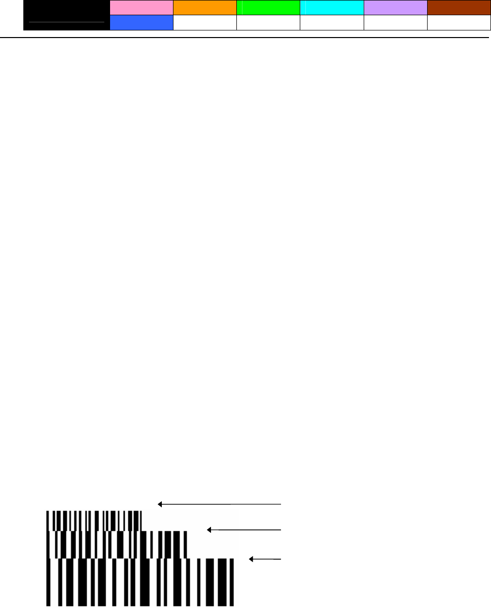
- 111 -
GS w n
CT-S280 CT-S300 CT-S2000 CT-S4000 BD2-2220 CT-S310
support model PMU2XXX
[Function] Specifying the horizontal size (magnification) of bar code
[Code] <1D>H<77>H<n>
[Range] 2≦n≦6
[Outline] [The specification which is common to the model]
Selecting bar code width.
[Default] n=3
[Sample Program]
LPRINT CHR$(&H1D);"h"; CHR$(30);
LPRINT CHR$(&H1D);"w"; CHR$(2);
GOSUB BC
LPRINT CHR$(&H1D);"h"; CHR$(50);
LPRINT CHR$(&H1D);"w"; CHR$(3);
GOSUB BC
LPRINT CHR$(&H1D);"h"; CHR$(80);
LPRINT CHR$(&H1D);"w"; CHR$(4);
GOSUB BC
END
BC:
LPRINT CHR$(&H1D);"k";
LPRINT CHR$(4);
LPRINT "12"; CHR$(0);
RETURN
[Print Results]
Height = 30, Magnification = 2
Height = 50, Magnification = 3
Height = 80, Magnification = 4
- 112 -
2.2.13 Commands for Non-volatile Memory
GS ( C pL pH m fn b [c1 c2][d1...dk]
CT-S280 CT-S300 CT-S2000 CT-S4000 BD2-2220 CT-S310
support model PMU2XXX
[Function] Editing user NV memory
[Outline] [The specification which is common to the model]
• Erases/stores/sends data of user NV memory area and sends the use amount/remaining capacity.
• Executes edit processing of user NV memory specified by function code (fn).
fn Code
Function
No. Function
0,48 GS ( C pL pH m fn b c1 c2 Function0 Erases specified record.
1,49 GS ( C pL pH m fn b c1 c2 d1…dk Function1 Stores data in specified record.
2,50 GS ( C pL pH m fn b c1 c2 Function2 Sends data stored in specified record.
Sends capacity of use
3,51 GS ( C pL pH m fn b Function3 (number of bytes).
Sends remaining capacity
4,52 GS ( C pL pH m fn b Function4 (number of bytes).
Sends key code list of stored
5,53 GS ( C pL pH m fn b Function5 record.
Erases all areas of user NV
6,54 GS ( C pL pH m fn b d1 d2 d3 Function6 memory in a lump.
• pL, PH specifies the number of bytes of “m” and the following to (pL + pH x 256).
• c1, c2 specifies key code (ID code of record).
• Total capacity of user NV memory can be specified as any of [1K, 64K, 128K, 192K]bytes by GS ( E.
Default value is 192K byte.
[Caution] • Frequent use of this command may result in damage of NV memory. Use the Write command to
NV memory in consideration of [10 times max./day].
• Following the processing of this command, printer Busy may occur during writing data in NV
memory. While the printer is Busy, it stops receiving process. Therefore, data transmission
(including real-time command) from host is prohibited.

- 113 -
fn=0、48: Function 0 Erasing Specified Record
GS ( C pL pH m fn b kc1 kc2
[Code] <1D>H<28>H<43>H<pL><pH><m><fn><b>[c1 c2]
[Range] (pL+pH×256)=5(pL=5、pH=0)
m=0
fn=0、48
b=0
32≦c1≦126
32≦c2≦126
[Outline] [The specification which is common to the model]
Erases the record specified by c1, c2 stored in user NV memory.
fn=1、49: Function 1 Storing Data to Specified Record
GS ( C pL pH m fn b c1 c2 d1...dk
[Code] <1D>H<28>H<43>H<pL><pH><m><fn><b>[c1 c2][d1...dk]
[Range] 6≦(pL+pH×256)≦65535(0≦pL≦255、0≦pH≦255)
m=0
fn=1、49
b=0
32≦c1≦126
32≦c2≦126
32≦d≦254
k=(pL+pH×256)-5
[Outline] [The specification which is common to the model]
• Stores data to the record specified by c1, c2.
• When the data is present in NV memory, it is replaced by new data.
- 114 -
fn=2、50: Function 2 Sending Data Stored in Specified Record
GS ( C pL pH m fn b c1 c2
[Code] <1D>H<28>H<43>H<pL><pH><m><fn><b> [c1 c2]
[Range] (pL+pH×256)=5(pL=5、pH=0)
m=0
fn=2、50
b=0
32≦c1≦126、32≦c2≦126
[Outline] [The specification which is common to the model]
Sends data stored in the record specified by c1, c2 in user NV memory.
Hex. Decimal Data Size
Header 37H 55 1byte
Identifier 70H 112 1byte
Status 40H or41H 64 or 65 0~80bytes
Data 20H~FEH 32~254 1byte
NUL 00H 0 1byte
Transmission data in case specified record cannot be detected is as shown below.
Hex. Decimal Data Size
Header 37H 55 1byte
Identifier 70H 112 1byte
Status 40H 64 1byte
NUL 00H 0 1byte
When 40 or more key codes exist, they are divided in units of 40 maximum and the rest to
be sent.
• Status with a group of consecutive transmit data groups is 41H.
• Status without a group of consecutive transmit data is 40H.
After sending [Header - NUL], a response is received from host and next processing
corresponding to the response is executed.
• In case of “Status (with continuous block): hexadecimal number = 41H / decimal number = 65”・
Response Content of Processing
ASCII Decimal
ACK 6
Sends next data group.
NAK 21
Resends previous data group.
CAN 24
Cancels processing.
• In case of “Status (last block): hexadecimal number = 40H / decimal number = 64”
Response Content of Processing
ASCII Decimal
ACK 6
Terminates processing.
NAK 21
Resends previous data group.
CAN 24
Cancels processing.
- 115 -
fn=3、51: Function 3 Sending Use Amount
GS ( C pL pH m fn b
[Code] <1D>H<28>H<43>H<pL><pH><m><fn><b>
[Range] (pL+pH×256)=3(pL=3、pH=0)
m=0
fn=3、51
b=0
[Outline] [The specification which is common to the model]
Sends the use amount of user NV memory (number of bytes of used area).
[Caution] • This command uses 20 bytes for user NV management information beforehand and
sends the use amount of user NV memory by 20 bytes more than actual size.
Hex. Decimal Data Size
Header 37H 55 1byte
Identifier 28H 40 1byte
Capacity of use 30H~39H 48~57 1~6 bytes
NUL 00H 0 1byte
fn=4、52: Function 4 Sending Remaining Capacity
GS ( C pL pH m fn b
[Code] <1D>H<28>H<43>H<pL><pH><m><fn><b>
[Range] (pL+pH×256)=3(pL=3、pH=0)
m=0
fn=4、52
b=0
[Outline] [The specification which is common to the model]
Sends the remaining capacity of user NV memory (number of bytes of unused area).
[Caution] • This command uses 20 bytes for user NV management information beforehand and
sends the remaining capacity user NV memory by 20 bytes less than actual size.
Hex. Decimal Data Size
Header 37H 55 1byte
Identifier 29H 41 1byte
Capacity of use 30H~39H 48~57 1~6bytes
NUL 00H 0 1byte
- 116 -
fn=5、53: Function 5 Sending Key Code List of Stored Record
GS ( C pL pH m fn b
[Code] <1D>H<28>H<43>H<pL><pH><m><fn><b>
[Range] (pL+pH×256)=3(pL=3、pH=0)
m=0
fn=5、53
b=0
[Outline] [The specification which is common to the model]
Sends key code list of record existing in user NV memory.
Hex. Decimal Data size
Header 37H 55 1byte
Identifier 71H 113 1byte
Status 40Hor41H 64or65 1byte
2~80 bytes
Data 20H~FEH 32~254
NUL 00H 0 1byte
• Data is a data group with a list of key codes.
Transmission data group when record is not detected is as shown below.
Hex. Decimal Data Size
Header 37H 55 1byte
Identifier 71H 113 1byte
Status 40H 64 1byte
NUL 00H 0 1byte
After sending [Header - NUL], receives a response from the host and executes the next processing
corresponding to the response.
• In case of “Status (with continuous block): hexadecimal number = 41H / decimal number = 65”
Response Content of Processing
ASCII Decimal
ACK 6 Sends next data group.
NAK 21 Resends previous data group.
CAN 24 Cancels processing.
• In case of “Status (last block): hexadecimal number = 40H / decimal number = 64”
Response Content of Processing
ASCII Decimal
ACK 6 Terminates processing.
NAK 21 Resends previous data group.
CAN 24 Cancels processing.

- 117 -
fn=6、54: Function 6 Erasing All User NV Memory Area in a Lump
GS ( C pL pH m fn b [d1 d2 d3]
[Code] <1D>H<28>H<43>H<pL><pH><m><fn><b>[d1 d2 d3]
[Range] (pL+pH×256)=6(pL=6、pH=0)
m=0
fn=6、54
b=0
d1=67(“C”)
d2=76(“L”)
d3=82(“R”)
[Outline] [The specification which is common to the model]
Erases all areas of user NV memory in a lump.
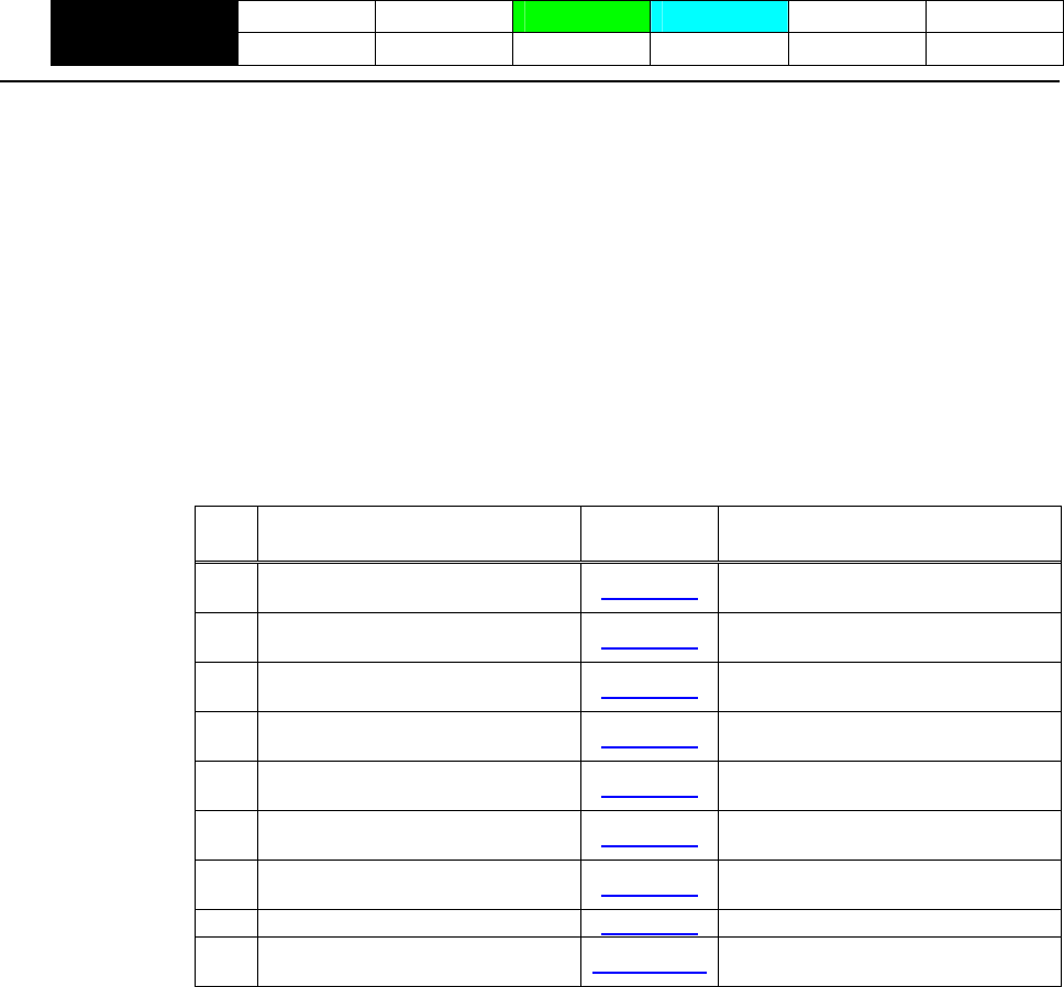
- 118 -
GS ( L pL pH m fn [parameter]
GS 8 L p1 p2 p3 p4 m fn [parameter]
CT-S280 CT-S300 CT-S2000 CT-S4000 BD2-2220 CT-S310
support model PMU2XXX
[Function] Specifying graphics data
[Code] <1D>H<28>H<4C>H<pL><pH><m><fn>
<1D>H<38>H<4C>H<p1><p2><p3><p4><m><fn>
* In the explanation of function, the code of GS ( L is used.
• GS ( L and GS 8 L ) are the same function.
• When [parameter] exceeds 65533 bytes in each function, GS 8 L is used.
[Outline] [The specification which is common to the model]
Executes the processing related to the graphics data specified by the function code (fn).
Function
No.
fn Code Function
Sends NV graphics memory
0,48 GS ( L pL pH m fn Function48 capacity.
Prints graphics data stored in print
buffer.
2,50 GS ( L pL pH m fn Function50
Sends the remaining amount of NV
graphics memory.
3,51 GS ( L pL pH m fn Function51
Sends key code list of defined NV
graphics.
64 GS ( L pL pH m fn d1 d2 Function64
Erases all data of NV graphics in a
lump.
65 GS ( L pL pH m fn d1 d2 d3 Function65
Erases the specified NV graphics
data.
66 GS ( L pL pH m fn kc1 kc2 Function66
GS ( L pL pH m fn a kc1 kc2 b xL
xH yL yH [c d1…dk]1…[c d1…dk]b
Defines raster graphics data to NV
memory.
67 Function67
69 GS ( L pL pH m fn kc1 kc2 x y Function69 Prints the specified NV graphics.
GS ( L pL pH m fn a bx by c xL xH
yL yH d1…dk
Stores raster graphics data to print
buffer.
112 Function 112
• pL, pH specifies the number of bytes or “m” and later to (pL + pH×256).
[Caution] • Frequent use of this command may result in damage of NV memory. Use the Write command to
NV memory in consideration of [10 times max./day].
• Following the processing of this command, printer Busy may occur during writing data in NV
memory. While the printer is Busy, it stops receiving process. Therefore, data transmission
(including real-time command) from host is prohibited.
- 119 -
fn=0、48: Function 48 Sending NV Graphics Memory Capacity
GS ( L pL pH m fn
[Code] <1D>H<28>H<4C>H<pL><pH><m><fn>
[Range] (pL+pH×256)=2(pL=2、pH=0)
m=48
fn=0、48
[Outline] [The specification which is common to the model]
Sends all capacity of NV graphics area in the number of bytes.
Hex. Decimal Data Size
Header 37H 55 1 byte
Identifier 30H 48 1 byte
Data 30H~39H 48~57 1 ~ 6 bytes
NUL 00H 0 1 byte
• Converts all capacity to character code expressed in decimal notation and sends it from higher
digit.
• Data size is variable.
• All definition area can be specified by GS ( E out of [0, 64K, 128K, 192K, 256K, 320K, 384K].
Default value is 384k bytes
fn=2、50: Function 50 Printing Graphics Data Stored in Print Buffer
GS ( L pL pH m fn
[Code] <1D>H<28>H<4C>H<pL><pH><m><fn>
[Range] (pL+pH×256)=2(pL=2、pH=0)
m=48
fn=2、50
[Outline] [The specification which is common to the model]
• Prints the graphics data stored in the print buffer in the processing of Function 112.
• Executes paper feeding corresponding to the number of dots in Y direction of graphics stored in
the print buffer.
- 120 -
fn=3、51: Function 51 Sending the Remaining Amount of NV Graphics Memory
GS ( L pL pH m fn
[Code] <1D>H<28>H<4C>H<pL><pH><m><fn>
[Range] (pL+pH×256)=2(pL=2、pH=0)
m=48
fn=3、51
[Outline] [The specification which is common to the model]
Sends the remaining amount of NV graphics area (number of bytes of unused area).
Hex. Decimal Data Size
Header 37H 55 1 byte
Identifier 31H 49 1 byte
Data 30H~39H 48~57 1 ~ 6 bytes
NUL 00H 0 1 byte
• Converts the remaining amount to character code expressed in decimal notation and sends it from
higher digit.
• Data size is variable.
- 121 -
fn=64: Function 64 Sending Key Code List of Defined NV Graphics
GS ( L pL pH m fn d1 d2
[Code] <1D>H<28>H<4C>H<pL><pH><m><fn><d1><d2>
[Range] (pL+pH×256)=4(pL=4、pH=0)
m=48
fn=64
d1=75(“K”)
d2=67(“C”)
[Outline] [The specification which is common to the model]
Sends the key code list of defined NV graphics.
• When key code list is present
Hex. Decimal Data Size
Header 37H 55 1 byte
Identifier 72H 114 1 byte
Status 40Hor41H 64or65 1 byte
Data 30H~39H 48~57 2~ 80 bytes
NUL 00H 0 1 byte
• When key code is not present
Hex.
Decimal Data Size
Header 37H 55 1 byte
Identifier 72H 114 1 byte
Data 40H 64 1 byte
NUL 00H 0 1 byte
When 40 or more key codes are present, they are sent by being divided in unit of 40max.
• Status with continuous transmission data group is 41H.
• Status without continuous transmission data group is 40H.
After sending [Header - NUL], receives a response from the host and executes the next processing
corresponding to the response.
• In case of “Status (with continuous block): hexadecimal number = 41H / decimal number = 65”
Response Content of Processing
ASCII Decimal
ACK 6 Sends next data group.
NAK 21 Resends previous data group.
CAN 24 Cancels processing.
• In case of “Status (last block): hexadecimal number = 40H / decimal number = 64”
Response Content of Processing
ASCII Decimal
ACK 6
Terminates processing.
NAK 21
Resends previous data group.
CAN 24
Cancels processing.

- 122 -
fn=65: Function 65 Erasing All Data of NV Graphics in a Lump
GS ( L pL pH m fn d1 d2 d3
[Code] <1D>H<28>H<4C>H<pL><pH><m><fn><d1><d2><d3>
[Range] (pL+pH×256)=5(pL=5、pH=0)
m=48
fn=65
d1=67(“C”)
d2=76(“L”)
d3=82(“R”)
[Outline] [The specification which is common to the model]
Erases all defined data of NV graphics in a lump.
fn=66: Function 66 Erasing Specified NV Graphics Data
GS ( L pL pH m fn kc1 kc2
[Code] <1D>H<28>H<4C>H<pL><pH><m><fn><kc1><kc2>
[Range] (pL+pH×256)=4(pL=4、pH=0)
m=48
fn=66
32≦kc1≦126
32≦kc2≦126
[Outline] [The specification which is common to the model]
Erases the NV graphics data defined by key code (kc1, kc2).
- 123 -
fn=67: Function 67 Defining Raster Type Graphics Data to NV Memory
GS ( L pL pH m fn a kc1 kc2 b xL xH yL yH
[c d1...dk]1...[c d1...dk]b
[Code] <1D>H<28>H<4C>H<pL><pH><m><fn><a><kc1><kc2><b><xL><xH><yL><yH>
[c d1…d2]1…[c d1…dk]b
[Range] Parameter of GS ( L
12≦(pL+pH×256)≦65535(0≦pL≦255、0≦pH≦255)
Parameter of GS 8 L
12≦(p1+p2×256+p3×65536+p4×16777216)≦4294967295
(0≦p1≦255、0≦p2≦255、0≦p3≦255、0≦p4≦255)
Common parameter of GS ( L, GS 8 L
m=48
fn=67
a=48
32≦kc1≦126、32≦kc2≦126
b=1、2
1≦(xL+xH×256)≦8192
1≦(yL+yH×256)≦2304
c=49(When monochrome color paper is specified)、c=49、50(When 2-color paper is specified)
0≦d≦255
k=(int((xL+xH×256)+7/8)×(yL+yH×256))
All defined areas can be specified by GS ( E from [0, 64K, 128K, 192K, 256K, 320K, 384K] bytes.
Default value is 384K bytes.
[Outline] [The specification which is common to the model]
Defines raster type graphics data to NV memory.
• “b” specifies the number of data colors.
• xL, xH specifies the horizontal direction of defined data to (xL + xH × 256).
• yL, yH specifies the vertical direction of defined data to (yL + yH × 256).
• “c” specifies the color of defined data.
Color of Defined Data c
49 1st color
50 2nd color
• 1st color denotes black (high energy) in the specified 2-color thermal paper.
• 2nd color denotes red (low energy) in the specified 2-color thermal paper.
[Caution] When multiple colors is specified by “b” and the same color is selected by “c”, the command
processing is terminated at that point, validating the defined data processed so far and the
remaining data is read and discarded.

- 124 -
fn=69: Function 69 Printing Specified Graphics
GS ( L pL pH m fn kc1 kc2 x y
[Code] <1D>H<28>H<4C>H<pL><pH><m><fn><kc1><kc2><x><y>
[Range] (pL+pH×256)=6(pL=6、pH=0)
m=48
fn=69
32≦kc1≦126
32≦kc2≦126
x=1、2
y=1、2
[Outline] [The specification which is common to the model]
Prints the NV graphics data defined by key code (kc1, kc2) as large as x times horizontally/y times
vertically.

- 125 -
fn=112: Function 112 Storing Raster Type Graphics Data to Print Buffer
GS ( L pL pH m fn a bx by c xL xH yL yH d1...dk
[Code] <1D>H<28>H<4C>H<pL><pH><m><fn><a><bx><by><c><xL><xH><yL><yH>[d1…dk]
[Range] Parameter of GS ( L
11≦(pL+pH×256)≦65536(0≦pL≦255、0≦pH≦255)
Parameter of GS 8 L
11≦(p1+p2×256)+p3×65536+p4×16777216≦4294967295
(0≦p1≦255、0≦p2≦255、0≦p3≦255、0≦p4≦255)
Common parameter of GS ( L, GS 8 L
m=48
fn=112
a=48
bx=1、2
by=1、2
c=49(When monochrome color paper is specified) 、c=49、50 (When 2-color paper is specified)
1≦(xL+xH×256)≦1024
When monochrome color paper is specified
1≦(yL+yH×256)≦1662(with by = 1)
1≦(yL+yH×256)≦831(with by = 2)
When 2-color paper is specified
1≦(yL+yH×256)≦831(with by = 1)
1≦(yL+yH×256)≦415(with by = 2)
0≦d≦255
k=(int((xL+xH×256)+7/8)×(yL+yH×256)
[Outline] [The specification which is common to the model]
Stores raster type graphics data to print buffer as large as x times horizontally/y times vertically.
• xL, xH specifies the horizontal direction of raster graphics data to (xL + xH x 256).
• yL, yH specifies the vertical direction of raster graphics data to (yL + yH x 256).
• “c” specifies the color of print data.
c Color of Print Data
49 1st color
50 2nd color
• 1st color denotes black (high energy) in the specified 2-color thermal paper.
• 2nd color denotes red (low energy) in the specified 2-color thermal paper.
[Caution] In STANDARD MODE, each color can be defined only once.

- 126 -
GS g 0 m nL nH
CT-S280 CT-S300 CT-S2000 CT-S4000 BD2-2220 CT-S310
support model PMU2XXX
[Function] Initializing maintenance counter
[Code] <1D>H<67>H<30>H<m><nL><nH>
[Range] m=0
20≦(nL+nH×256)≦70(nL=20、21、50、70、nH=0)
[Outline] [The specification which is common to the model]
Set the value of resettable maintenance counter specified to 0.
nL, nH are used to set the maintenance counter number to (nL+nH×256).
Counter Number Counter [Unit]
Hex. Decimal
14 20
Paper-feed line[line]
15 21
Head powering count [times]
32 50
Auto-cutter drive count [times]
46 70
Product operation time[hours]
[Caution] • This command, if used frequently, may destroy NV memory, thus write command to NV memory
shall be used less than [10 times/day] as a guideline.
• Along with processing this command, during data-writing to NV memory, printer BUSY may occur.
During the printer BUSY, to stop receive processing, this printer prohibits the data sending
(including real-time command) from host.
- 127 -
GS g 2 m nL nH
CT-S280 CT-S300 CT-S2000 CT-S4000 BD2-2220 CT-S310
support model PMU2XXX
[Function] Sending maintenance counter
[Code] <1D>H<67>H<32>H<m><nL><nH>
[Range] m=0
20≦(nL+nH×256)≦198
nL=20、21、50、70、148、149、178、198
nH=0
[Outline] [The specification which is common to the model]
Send the maintenance counter value specified.
nL, nH are used to set the maintenance counter number to (nL+nH×256).
Counter Number Counter [Unit] Counter Type
Hex. Decimal
14 20
Paper-feed line[line] Resettable
15 21
Head powering count [times] Resettable
32 50
Auto-cutter drive count [times] Resettable
46 70
Product operation time[hours] Resettable
94 148
Paper-feed line[line] Accumulated
95 149
Head powering count [times] Accumulated
B2 178
Auto-cutter drive count [times] Accumulated
C6 198
Product operation time[hours] Accumulated
• Configuration of data to be sent is shown below for the maintenance counter.
Hex. Decimal Data Count
Header 5FH 95
1 byte
30H~39H 48~57
Data 1 - 10 bytes
NUL 00H 0
1 byte
[Caution] • During sending block data (maintenance counter value), real-time status and ASB status shall not
be sent. Thus, during sending the data, printer status can not be notified.
• Counter value sent by this command is only a guideline value. Due to an error occurrence and
power off timing, figure data may have an error.
• To update the flash memory, write the flash memory if any change occurs in the
maintenance counter when the period where the printer is not in operation (printing,
paper feeding, drawer, or cutting) lasts about 10 seconds, 2 minutes, and 1 hour.
• If change occurs in each counter, data on RAM is updated correspondingly.

- 128 -
FS p n m
CT-S280 CT-S300 CT-S2000 CT-S4000 BD2-2220 CT-S310
support model PMU2XXX
[Function] Printing the download NV bit images
[Code] <1C>H<70>H<n><m>
[Range] 1≦n≦255、 0≦m≦3、48≦m≦51
[Outline] [The specification which is common to the model]
This command prints the download NV bit images (n) using a specified mode (m).
Dot Density in Dot Density in
Horizontal Direction
m Mode Name Vertical Direction
0,48 NORMAL MODE 203dpi 203dpi
1,49 DOUBLE WIDTH MODE 203dpi 101dpi
2,50 DOUBLE HEIGHT MODE 101dpi 203dpi
3,51 QUADRUPLE SIZE MODE 101dpi 101dpi
• “n” denotes the number of the download bit image.
• “m” denotes the bit image mode.
[Caution] • When the specified NV bit image “n” is undefined, this command is invalid.
• When the STANDARD MODE is selected, this command is valid only when there is no data in the
print buffer.
• This command is invalid when PAGE MODE is selected.
• Any printing modes except the upside-down printing mode (i.e. emphasis, double strike,
underlining, character size, inverted character printing, 90°-right-turned) are not affected.
• When the printing area set by the functions GS L and GS W is not enough for one vertical line of
the download NV bit image, the line alone is dealt with as follows.
One vertical line of the bit image is 1 dot in NORMAL MODE (m = 0, 48) and DOUBLE HEIGHT
MODE (m = 2, 50), and it is 2 dots in double WIDTH MODE (m = 1, 49) and QUADRUPLE SIZE
MODE (m = 3, 51).
(1) The printing area is extended to the right side within the limits of the printing area so that one
vertical line of the download NV bit image can be printed.
(2) When a sufficient printing area cannot be maintained even after executing (1), the printing
area is extended to the left side. (The left margin is reduced.)
• When the size of a bit image exceeds the limits of the printing area, the data within the limits of
the printing area will be printed but the parts exceeding the limit will not be printed.
• Regardless of the amount of line feed set with ESC 2 and ESC 3, NORMAL MODE and DOUBLE
WIDTH MODE execute a paper feed of (height “n” of NV bit image) dots while DOUBLE HEIGHT
MODE and QUADRUPLE SIZE MODE execute a paper feed of (height “n” of NV bit image x2) dots.
• At the completion of the bit image printing, the head of the line will be used for the next printing
position and normal data processing will take place.
[See Also] ESC *、FS q、GS /、GS v 0
- 129 -
[Sample Program]
GOSUB SETNV
LPRINT CHR$(&H1C); “p”; CHR$(1); CHR$(0); DATA &H00, &H00, &H00, &H00, &H07, &HF0
LPRINT CHR$(&HA); DATA &H1E, &H78, &H18, &H18, &H30, &H0C
LPRINT CHR$(&H1C); “p”; CHR$(1); CHR$(3); DATA &H30, &H0C, &H30, &H0C, &H30, &H0C
LPRINT CHR$(&HA); DATA &H1C, &H18, &H18, &H18, &H00, &H00
END DATA &H00, &H00, &H00, &H00, &H3F, &HFC
SETNV: DATA &H3F, &HFC, &H00, &H00, &H00, &H00
LPRINT CHR$(&H1C);"q"; CHR$(1); DATA &H30, &H00, &H30, &H00, &H30, &HF0
LPRINT CHR$(8); CHR$(0); CHR$(2); CHR$(0); DATA &H30, &H00, &H3F, &HFC, &H3F, &HFC
FOR I=1 TO 128 DATA &H30, &H00, &H30, &H00, &H30, &HF0
READ D DATA &H00, &H00, &H3F, &HFC, &H3F, &HFC
LPRINT CHR$(D); DATA &H00, &H00, &H00, &H1C, &H30, &H3C
NEXT I DATA &H30, &HFC, &H31, &HCC, &H33, &H8C
RETURN DATA &H3E, &H0C, &H3C, &H0C, &H30, &H0C
DATA &H00, &H00, &H00, &H00, &H3F, &HFC
DATA &H3F, &HFC, &H31, &H8C, &H31, &H8C
DATA &H31, &H8C, &H31, &H8C, &H31, &H8C
DATA &H31, &H8C, &H00, &H0C, &H00, &H00
DATA &H00, &H00, &H3F, &HFC, &H3F, &HFC
DATA &H1C, &H00, &H07, &H00, &H01, &HC0
DATA &H00, &HE0, &H00, &H38, &H3F, &HFC
DATA &H3F, &HFC, &H00, &H00, &H00, &H00
DATA &H00, &H00
[Print Results]
CITIZEN … When Normal mode is specified
CITIZEN … When Quadruple size mode is specified

- 130 -
FS q n [xL xH yL yH d1...dk]1...[xL xH yL yH d1...dk]n
CT-S280 CT-S300 CT-S2000 CT-S4000 BD2-2220 CT-S310
support model PMU2XXX
[Function] Defining the download NV bit image
[Code] <1C>H<71>H<n>[<xL><xH><yL><yH><d1…dk>]1…[<xL><xH><yL><yH><d1…dk>]n
[Range] 1≦n≦255、 0≦xL≦255
0≦xH≦3 but, 1≦(xL+xH×256)≦1023
0≦yL≦255
0≦yH≦1 but, 1≦(yL+yH×256)≦288
0≦d≦255
k=(xL+xH×256)×(yL+yH×256)×8
CT-S280/CT-S300/BD2-2220/CT-S310/PMU2XXX
Total definition area=256K bytes
CT-S2000/CT-4000
Total definition area=384K bytes
[Outline] [The specification which is common to the model]
This command defines the specified NV bit image.
• “n” denotes the number of bit images to be defined.
• xL and xH denote the horizontal size of one NV bit image as (xL+xH×256)×8 dots.
• yL and yH denote the vertical size of one NV bit image as (yL+yH×256 )×8 dots
[Caution] • Because all the NV bit images previously defined by this command are deleted, it is not possible to
redefine any one of the previously defined multiple data. All the data must be resent.
• Any mechanical operation such as opening the cover, initializing the printer head position, or using
the paper-feed switch etc can’t execute from the execution of this command until the completion
of the hardware reset,
• When the STANDARD MODE is selected, this command is only valid when it is written at the head
of a line.
• This command is invalid when PAGE MODE is selected.
• This command becomes valid after the 7 bytes of <FS q n xL xH yL yH> are processed as normal
values.
• When data which exceeds the remaining capacity of the defined area is specified by xL, xH, yL, yH,
outside-defined-area arguments will be processed.
• When outside-defined-area arguments are processed for the first bit image data group, this
command becomes invalid.
• If outside-defined-area arguments are processed for the second or subsequent NV bit image data
groups, the processing of this command is suspended, and a writing process into the non-volatile
memory starts. At this time, the NV bit image being defined becomes invalid (Undefined), but the
preceding NV bit images are valid.
• “d” denotes the definition data. Bits which correspond to dots to be printed are represented as “1”,
and those not to be printed as “0”.
• The definition will start from NV bit image number 01H and n-number bit images will be defined in
ascending order. Therefore, the first data group [xL xH yL yH d1… dk] becomes NV bit image
number 01H, and the last data group [xL xH yL yH d1… dk] becomes NV bit image number 0nH.
These numbers of NV bit images coincide with those specified with FS p.

- 131 -
• The definition data of one NV bit image consists of [xL xH yL yH d1… dk]. Therefore, when only
one NV bit image is defined, n = 1; the data group [xL xH yL yH d1… dk] is manipulated once, and
([Data: (xL + xH x256) x( yL + yH x256 ) x8 ] + [Header: 4]) bytes of non-volatile memory is
used to store it
• The maximum definition area of printer depends on model. Multiple NV bit images can be defined,
but bit images of which total size (Bit image data + Header) exceeds capacity of definition area
can not be defined.
• The printer state will change to BUSY just before the writing operation into the non-volatile
memory begins. Also, the printer state will change to BUSY just before the writing operation
begins regardless of the state of the memory switch even at a printer that have a memory switch
1-3[Busy condition]
• While this command is being executed, it is not possible to send ASB status or to detect the printer
status even when the ASB function is selected.
• If this command is sent while a macro is still being defined, the definition process will be stopped
and the execution of this command will start.
• NV bit images that are defined already are not initialized by using ESC @ command, or by
resetting the printer or turning the power off.
• The command only executes definition of NV bit image, but not start printing. The printing of NV
bit image will be executed by FS p.
• Because frequent writing in the non-volatile memory can destroy the memory, the writing
command should be used less than 10 times a day.
• It may happen that the printer becomes BUSY during the process of writing data into the
non-volatile memory in the execution of this command. When the printer becomes BUSY, it will
stop receiving data. Therefore, sending data from the host (including real time command) is
prohibited.
[See Also] FS p、GS *
[Sample Program]
[Print Results]
Refer to the Sample Program and Printing Results for FS p.
- 132 -
2.2.14 Kanji Control Commands
FS ! n
CT-S280 CT-S300 CT-S2000 CT-S4000 BD2-2220 CT-S310
support model PMU2XXX
[Function] Collectively setting Kanji print mode
[Code] <1C>H<21>H<n>
[Range] 0≦n≦255
[Outline] [The specification which is common to the model]
Collectively sets Kanji print mode.
Each bit of “n” has the following meaning:
Value
Bit Function 0 1
0 Undefined ― ―
1 Undefined ― ―
2 Double-width enlargement Canceled Specified
3 Double-height enlargement Canceled Specified
4 Undefined ― ―
5 Undefined ― ―
6 Undefined ― ―
7 Underline Canceled Specified
[Caution] • Setting both double-height and double-width enlargement causes four times enlargement.
• Underline is applied to all width of printed characters but not to the part skipped by HT. Underline
is not applied to the character rotated by 90° clockwise.
• Thickness of underline is the value set by FS – (defaulted to 1 dot width).
[Default] n=0
[See Also] FS -、FS W、GS !
- 133 -
FS &
CT-S280 CT-S300 CT-S2000 CT-S4000 BD2-2220 CT-S310
support model PMU2XXX
[Function] Setting Kanji mode
[Code] <1C>H<26>H
[Outline] [The specification which is common to the model]
Sets Kanji mode.
Japanese Kanji specifications:
This command is invalid when Kanji code system is Shift JIS.
Kanji codes are processed in the order of the first byte and second byte.
This code is defaulted to the state of canceling Kanji mode.
[The specification which depend on the model]
CT-S280/CT-S300/CT-S2000/CT-S4000/CT-S310
Multilingual specifications (Hangul, Chinese):
Kanji codes are processed in the order of the first byte and second byte.
This code is defaulted to the state of setting Kanji mode.
[See also] FS .、FS C
[Sample Program] [Print Results]
LPRINT CHR$(&H1C);"&"; 漢字
4A;z
When setting Kanjimode
When canceling Kanji mode
LPRINT CHR$(&H34); CHR$(&H41);
LPRINT CHR$(&H3B); CHR$(&H7A);
LPRINT CHR$(&HA);
LPRINT CHR$(&H1C);".";
LPRINT CHR$(&H34); CHR$(&H41);
LPRINT CHR$(&H3B); CHR$(&H7A);
LPRINT CHR$(&HA);
- 134 -
FS - n
CT-S280 CT-S300 CT-S2000 CT-S4000 BD2-2220 CT-S310
support model PMU2XXX
[Function] Setting/canceling Kanji underline
[Code] <1C>H<2D>H<n>
[Range] 0≦n≦2、48≦n≦50
[Outline] [The specification which is common to the model]
Sets or cancels Kanji underline.
n Function
0、48 Cancels Kanji underline
1、49 Sets 1-dot width Kanji underline
2、50 Sets 2-dot width Kanji underline
[Caution] • Underline is applied to all width of printed characters but not applied to the part skipped by HT.
• Underline is not applied to the character rotated 90° clockwise.
[See Also] FS !
[Sample Program] [Print Results]
LPRINT CHR$(&H1C);"&";
LPRINT CHR$(&H1C);"-"; CHR$(0);
漢字漢字
Canceling Kanji underline
Setting Kanji underline
LPRINT CHR$(&H34); CHR$(&H41);
LPRINT CHR$(&H3B); CHR$(&H7A);
LPRINT CHR$(&H1C);"-"; CHR$(1);
LPRINT CHR$(&H34); CHR$(&H41);
LPRINT CHR$(&H3B); CHR$(&H7A);
LPRINT CHR$(&HA);
LPRINT CHR$(&H1C);".";

- 135 -
FS .
CT-S280 CT-S300 CT-S2000 CT-S4000 BD2-2220 CT-S310
support model PMU2XXX
[Function] Canceling Kanji mode
[Code] <1C>H<2E>H
[Outline] [The specification which is common to the model]
Cancels Kanji mode.
Japanese Kanji specifications:
This command is invalid when Kanji code system is Shift JIS.
This code is defaulted to the state of canceling Kanji mode.
[The specification which depend on the model]
CT-S280/CT-S300/CT-S2000/CT-S4000/CT-S310
Multilingual specifications (Hangul, Chinese):
Kanji codes are processed in the order of the first byte and second byte.
This code is defaulted to the state of setting Kanji mode.
[See Also] FS &、FS C
[Sample Program]
Refer to the Sample Program and Printing Results for FS &.

- 136 -
FS 2 a1 a2 [d]k
CT-S280 CT-S300 CT-S2000 CT-S4000 BD2-2220 CT-S310
support model PMU2XXX
[Function] Defining external character
[Code] <1C>H<32>H<a1>H<a2>H[<d>]k
[Range] Japanese Kanji specifications:
• In case of JIS code system
a1=<77>H,<21>H≦a2≦<7E>H
• In case of Shift JIS code system
a1=<EC>H,<40>H≦a2≦<7E>H、<80>H≦a2≦<9E>H
Multilingual specifications (Hangul, Chinese):
a1=<FE>H,<A1>H≦a2≦<FE>H
Common
0≦d≦255
k=72(FONTA: 24×24)
k=32(FONTC: 16×16)
CT-S2000/CT-S4000
k=60(FONTB: 20×24)
[Outline] [The specification which is common to the model]
• Defines external Kanji character.
• a1, a2 show Kanji code to define external character and definition of 94 characters are available.
• “d” is data to be defined and the number of data to be defined is 72 bytes of vertical 3 bytes × 24
dots.
• Each data is created by “1” for printed dot and “0” for unprinted dot.
[The specification which depend on the model]
CT-S280/CT-S300/CT-S2000/CT-S4000/CT-S310
• In multilingual specifications, font B, font C cannot define.
[Default] All are space.

- 137 -
[Sample Program]
LPRINT CHR$(&H1C);"&"; DATA &H00, &H00, &H00, &H00, &H00, &H00
GOSUB SETCHR DATA &H00, &H00, &H60, &H00, &H00, &HF0
LPRINT CHR$(&H77); CHR$(&H21); DATA &H00, &H01, &HF8, &H00, &H03, &HFC
LPRINT CHR$(&HA); DATA &H00, &H07, &HFE, &H00, &H0F, &HFF
LPRINT CHR$(&H1C);"."; DATA &H00, &H00, &HF0, &H00, &H00, &HF0
END DATA &H00, &H00, &HF0, &H00, &H00, &HF0
DATA &H00, &H00, &HF0, &H00, &H00, &HF0
SETCHR: DATA &H00, &H00, &HF0, &H00, &H00, &HF0
LPRINT CHR$(&H1C);"2"; DATA &H00, &H01, &HF0, &H1F, &HFF, &HF0
LPRINT CHR$(&H77); CHR$(&H21); DATA &H1F, &HFF, &HF0, &H1F, &HFF, &HE0
FOR I=1 TO 72 DATA &H1F, &HFF, &HC0, &H00, &H00, &H00
READ D DATA &H00, &H00,&H00, &H00, &H00, &H00
LPRINT CHR$(D);
NEXT I
RETURN
[Print Results]
Registered character
- 138 -
FS C n
CT-S280 CT-S300 CT-S2000 CT-S4000 BD2-2220 CT-S310
support model PMU2XXX
[Function] Selecting Kanji code system
[Code] <1C>H<43>H<n>
[Range] 0≦n≦1、48≦n≦49
[Outline] [The specification which is common to the model]
Selects Kanji code system.
Japanese Kanji specifications:
n Function
0,48 Selects JIS code system.
1,49 Selects Shift JIS code system.
[The specification which depend on the model]
CT-S280/CT-S300/CT-S2000/CT-S4000/CT-S310
Multilingual specifications (Hangul,):
n Function
0,48 Selects KS code system.
1,49 Selects Extend KS code system.
Multilingual specifications (Chinese):
This command is invalid
[Caution] [The specification which is common to the model]
• Kanji code valid in JIS code system is <21> ~ <7E>H for both 1st and 2nd bytes.
• Kanji code valid in Shift JIS code system is as follows:
1st byte is <81>H ~ <9F>H and <E0>H ~ <EF>H.
2nd byte is <40>H ~ <7E>H and <80>H ~ <FC>H.
[The specification which depend on the model]
CT-S280/CT-S300/CT-S2000/CT-S4000/CT-S310
• Codes valid for KS code system are as follows:
Special symbol: 2121h to 2C71h
Hangeul: 3021h to 487Eh
Area other than the above is SPACE.
• With Extend KS code
Special symbol: A1A1h to ACF1h
Hangeul: B0A1h to C8FEh
Area other than the above is SPACE.
[Default] n=0
- 139 -
[Sample Program] [Print Results]
LPRINT CHR$(&H1C);"&";
LPRINT CHR$(&H1C);"C"; CHR$(0);
漢字 ← Shift JIS code system printing
漢字 ← JIS code system printing
LPRINT CHR$(&H34); CHR$(&H41);
LPRINT CHR$(&H3B); CHR$(&H7A);
LPRINT CHR$(&HA);
LPRINT CHR$(&H1C);"C"; CHR$(1);
LPRINT CHR$(&H8A); CHR$(&HBF);
LPRINT CHR$(&H8E); CHR$(&H9A);
LPRINT CHR$(&HA);
LPRINT CHR$(&H1C);".";

- 140 -
FS S n1 n2
CT-S280 CT-S300 CT-S2000 CT-S4000 BD2-2220 CT-S310
support model PMU2XXX
[Function] Setting Kanji space amount
[Code] <1C>H<53>H<n1><n2>
[Range] 0≦n1≦255
0≦n2≦255
[Outline] [The specification which is common to the model]
• Sets both right and left space amount of Kanji in units of dot.
• Sets left space amount by [n1×(Basic calculation pitch)].
• Sets right space amount by [n2×(Basic calculation pitch)].
[Caution] • The right and left space amount in double-width mode are twice the setting.
• Setting independent line feed amount is possible in STANDARD MODE and PAGE MODE.
• Basic calculation pitch is set by GS P. Even if basic calculation pitch is changed by GS P after setting
space amount, there is no change in the amount of line feed.
When fractional number is caused by the calculation, it is corrected by the minimum pitch of
mechanism and the rest is discarded.
• In STANDARD MODE, basic calculation pitch (x) in horizontal direction is used.
• In PAGE MODE, the following operation occurs depending on the start point.
(1) When the start point is set at “upper left” or “lower right” by ESC T, basic calculation pitch (y)
of vertical direction (paper feed direction) is used.
(2) When the start point is set at “upper right” or “lower left” by ESC T, basic calculation pitch (x)
of horizontal direction (at right angle to paper feed direction)is used.
• The maximum right spacing is capable of approximately 31.906 mm (255/203 inches). A setting
greater than this maximum is trimmed to the maximum.
[Default] n1=0、n2=0
- 141 -
FS W n
CT-S280 CT-S300 CT-S2000 CT-S4000 BD2-2220 CT-S310
support model PMU2XXX
[Function] Setting/canceling four times enlargement of Kanji
[Code] <1C>H<57>H<n>
[Range] 0≦n≦255
[Outline] [The specification which is common to the model]
Sets or cancels four times enlargement of Kanji.
• “n” is valid only for the lowest bit (n0).
• Control by the lowest bit (n0) is shown as follows:
n0 Function
0 Cancels 4 times enlargement
1 Sets 4 times enlargement
Setting or canceling 4 times enlargement means setting or canceling both doubleheight and
double-width enlargements simultaneously.
[See Also] FS !
[Sample Program] [Print Results]
LPRINT CHR$(&H1C);"&";
漢字漢字
Canceling 4 times enlargement
Setting 4 times enlargement
LPRINT CHR$(&H1C);"W"; CHR$(0);
LPRINT CHR$(&H34); CHR$(&H41);
LPRINT CHR$(&H3B); CHR$(&H7A);
LPRINT CHR$(&H1C);"W"; CHR$(1);
LPRINT CHR$(&H34); CHR$(&H41);
LPRINT CHR$(&H3B); CHR$(&H7A);
LPRINT CHR$(&HA);
LPRINT CHR$(&H1C);".";
- 142 -
FS ( A pL pH fn […]
CT-S280 CT-S300 CT-S2000 CT-S4000 BD2-2220 CT-S310
support model PMU2XXX
[Function] Setting font attribute of Kanji
[Outline] Setting Kanji font attribute means execution of processing for Kanji font attribute by the value of
“fn” specified.
fn Function
48 Sets Kanji font
[Outline] [The specification which is common to the model]
This command is effective only for the Japanese Japanese Kanji specifications.
fn=48: Function 48 Set Kanji fonts
FS ( A pL pH fn m
[Code] <1C>H<28>H<4E>H <pL>< pH>< fn>< m>
[Range] (pL+pH×256)=2:(pL=2、pH=0)
fn=48
0≦m≦2、48≦n≦50
[Default] m=0
[Outline] [The specification which is common to the model]
Prints the succeeding characters with energy set for “m”.
This command is effective only for the Japanese Japanese Kanji specifications.
[The specification which depend on the model]
CT-S280/CT-S300/BD2-2220/CT-S310/PMU2XXX
m Function
0、48 Kanji font A(24×24)
1、49 invalid
2、50 Kanji font C(16×16)
CT-S2000/CT-S4000
m Function
0、48 Kanji font A(24×24)
1、49 Kanji font B(20×24)
2、50 Kanji font C(16×16)
- 143 -
2.2.15 Black Mark Control Commands
GS FF
CT-S280 CT-S300 CT-S2000 CT-S4000 BD2-2220 CT-S310
support model PMU2XXX
[Function] Printing and ejecting Black mark paper/ label paper
[Code] <1D>H<0C>H
[Outline] [The specification which is common to the model]
This command prints the data in the printer buffer and ejects Black mark paper/ label paper.
[The specification which depend on the model]
CT-S4000
• When auto cutter disabled is selected
(1)Feeds the printed label to the position to be cut by the manual cutter.
(2)Keeps waiting till cutting is made and FEED SW is pressed while blinking LED.
(3)If FEED SW is pressed, setting the first position of BM paper/label paper is carried
out.
• The printer is in the BUSY state till the processing of (3) is executed. If, however,
FEED SW is not pressed in 3 seconds, the same operation as that with FEED SW is
executed.
• When auto cutter enabled is selected
(1)The printed label is fed to the auto cutter position and full cutting is carried out.
(2)Setting the first position of next BM paper/label paper is carried out.
[Caution] Valid only if Black mark paper/ label paper is selected.
[See Also] FF、GS <
GS <
CT-S280 CT-S300 CT-S2000 CT-S4000 BD2-2220 CT-S310
support model PMU2XXX
[Function] Initializing the printer mechanism
[Code] <1D>H<3C>H
[Outline] [The specification which is common to the model]
Performs initializing operation at Black mark/ label similar to the initialization at power on.
[Caution] • This command is valid only when B.M paper/ label is chosen.
• Parameters configured by commands are not reset.
- 144 -
GS A m n
CT-S280 CT-S300 CT-S2000 CT-S4000 BD2-2220 CT-S310
support model PMU2XXX
[Function] Correcting the leader position of Black mark paper/ label paper
[Code] <1D>H<41>H<m><n>
[Range] 0≦m≦255
0≦n≦255
[Outline] [The specification which is common to the model]
This command sets the leader position of Black mark paper/ label paper in terms of correction value
set for the default position.
“m” denotes the correcting direction.
• “m” is valid only for the lowest bit (m0).
• Control by the lowest bit (m0) is shown as follows:
Correcting Direction m0
0 Corrects the leader position in the forward direction
1 Corrects the leader position in the reverse direction
• “n” denotes the correction value in units of n/203 inch.
[Caution] • This command is valid only when Black mark paper/ label paper is chosen.
• This command is ignored except immediately after the execution of a Black mark/ label positioning
command (FF, GS FF, GS A, GS <) or immediately after leader positioning performed on a paper
feed action with the FEED switch, power on, or cover closure.
• The maximum reverse correction span is 0.5 mm. Correction settings exceeding this value are
truncated into the maximum value. The leader position may be deviated due to paper flexure. For
reverse correction, exercise care so the leader position does not step out of the Black mark/ label.
• For forward correction, set the correction span by taking into account the Black mark/ label length
as the printable area changes before and after correction setting.
• In calculating a correction span, use the basic calculation pitch (y) for the vertical direction. The
fractional part contained in the calculation result should be corrected in units of the mechanism’s
minimum pitch, with the remaining fractional part truncated.
- 145 -
GS C 0 m n
CT-S280 CT-S300 CT-S2000 CT-S4000 BD2-2220 CT-S310
support model PMU2XXX
[Function] Setting the numbering print mode
[Code] <1D>H<43>H<30>H<m><n>
[Range] 0≦m≦5
0≦n≦2
[Outline] [The specification which is common to the model]
This command sets the numbering (serial number counter) print mode.
“m” denotes the number of print columns.
m = 0 Prints the columns indicated by numeral. In this case, “n” has no meaning.
m = 1 to 5 Indicates the maximum number of columns to be printed.
Prints the counter in “m” columns.
“n” specifies a printing position within the printing columns.
n = 0 Prints the data right justified. The blank columns are spaced.
n = 1 Prints the data right justified. The blank columns are filled with "0".
n = 2 Prints the data left justified. The right blank will become invalid.
[Caution] If either “m” or “n” has a value beyond their ranges, that setting will becomes invalid.
[Default] m=0、n=0
[See Also] GS C 1、GS C 2、GS C;、GS c
[Sample Program]
LPRINT CHR$(&H1D);"C0"; *CNT
LPRINT CHR$(0); CHR$(0); FOR I=1 TO 5
GOUSAB *CNT LPRINT CHR$(&H1D);"c";
LPRINT CHR$(&H1D);"C0"; NEXT I
LPRINT CHR$(1); CHR$(0); LPRINT CHR$(&HA);
GOUSAB *CNT RETURN
LPRINT CHR$(&H1D);"C0";
LPRINT CHR$(3);CHR$(0); [Print Results]
GOUSAB *CNT 12345
67890
11 12 13 14 15
016017018019020
21 22 23 24 25
Counts from 1 to 5 at m = 0 and n = 0.
Counts from 6 to 10 at m = 1 and n = 0.
Counts from11 to 15 at m = 3 and n = 0.
Counts from 16 to 20 at m = 3 and n = 1.
Counts from 21 to 25 at m = 3 and n = 2.
LPRINT CHR$(&H1D);"C0";
LPRINT CHR$(3); CHR$(1);
GOUSAB *CNT
LPRINT CHR$(&H1D);"C0";
LPRINT CHR$(3); CHR$(2);
GOUSAB *CNT
END
- 146 -
GS C 1 n1 n2 n3 n4 n5 n6
CT-S280 CT-S300 CT-S2000 CT-S4000 BD2-2220 CT-S310
support model PMU2XXX
[Function] Setting the numbering counter mode (A)
[Code] <1D>H<43>H<31>H<n1><n2><n3><n4><n5><n6>
[Range] 0≦n1、n2、n3、n4、n5、n6≦255
[Outline] [The specification which is common to the model]
This command sets the numbering (serial number counter) mode.
n1+n2×256 (n1 = remainder, n2 = quotient): Counter default
n3+n4×256 (n3 = remainder, n4 = quotient): Counter final value
n5: Counter step value
n6: Identical counter print counter
(n1+n2×256) < (n3+n4×256): Count-up system
(n1+n2×256) > (n3+n4×256): Count-down system
(n1+n2×256) = (n3+n4×256) or n5 = 0 or n6 = 0: Counter stop
[Default] n1+n2×256=1
n3+n4×256=65535
n5=1
n6=1
[See Also] GS C 0、GS C 2、GS C;、GS c
[Sample Program]
LPRINT CHR$(&H1D);"C0"; *CNT
LPRINT CHR$(3); CHR$(0); FOR I=1 TO 5
LPRINT CHR$(&H1D);"C1"; LPRINT CHR$(&H1D);"c";
LPRINT CHR$(50); CHR$(0); ¥ NEXT I
LPRINT CHR$(0); CHR$(0); ¥ LPRINT CHR$(&HA);
LPRINT CHR$(5); CHR$(2); RETURN
GOUSAB *CNT
LPRINT CHR$(&H1D);"C2";
LPRINT CHR$(5); CHR$(0); CHR$(10);
GOUSAB *CNT
END
[Print Results] When printing the counter value by setting a count-down range = 0
to 50, step value = 5, repeat count = 2, and starting value = 50.
50 45 40 0
50 50 45 45 40
5
When printing the counter value by setting a count-down range to 0
to 50, step value = 5, repeat count = 1, and starting value = 5, step
cleared.
- 147 -
GS C 2 n1 n2
CT-S280 CT-S300 CT-S2000 CT-S4000 BD2-2220 CT-S310
support model PMU2XXX
[Function] Setting the numbering counter
[Code] <1D>H<43>H<32>H<n1><n2>
[Range] 0≦n1≦255
0≦n2≦255
[Outline] [The specification which is common to the model]
This command sets the numbering (serial number counter) value.
n1+n2×256 (n1 = remainder, n2 = quotient) becomes a counter value.
[Caution] • If the counter is set with this command, a repeat count of the identical count will be cleared.
• If the counter value is beyond the range specified with the GS C1 or GS C; command, the counter
will be initialized.
[Default] Not defined.
[See Also] GS C 0、GS C 1、GS C ;、GS c
[Sample Program]
[Print Results]
See the Sample Program and Print Results for the GS C1 command.
- 148 -
GS C ; n1 ; n2 ; n3 ; n4 ; n5 ;
CT-S280 CT-S300 CT-S2000 CT-S4000 BD2-2220 CT-S310
support model PMU2XXX
[Function] Setting the numbering counter mode (B)
[Code] <1D>H<43>H<3B>H<n1><3B>H<n2><3B>H<n3><3B>H<n4><3B>H<n5><3B>H
<n1>、<n2>、<n3>、<n4>、<n5> are character codes.
[Range] 0≦n1、n2、n5≦65535
0≦n3、n4≦255
[Outline] [The specification which is common to the model]
This command sets the numbering (serial number counter) mode and a counter value.
n1: Counter default
n2: Counter final value
n3: Counter step value
n4: Identical counter print count
n5: Counter start value
n1 < n2: Count-up system
n1 > n2: Count-down system
n1 = n 2 or n3 = 0 or n4 = 0 : Counter stop
[Caution] • If the n5 counter start value is beyond the counter range specified with n1 and n2, it is assumed to
be n1 = n5.
• If each value of n1 through n5 contains the character code other than “0” through “9”, the printer
will invalidate the data up to that parameter and handle the subsequent data as normal data.
[Default] n1=1、n2=65535、n3=1、n4=1、n5=1
[See Also] GS C 0、GS C 1、GS C 2、GS c
- 149 -
GS c
CT-S280 CT-S300 CT-S2000 CT-S4000 BD2-2220 CT-S310
support model PMU2XXX
[Function] Print the counter
[Code] <1D>H<63>H
[Outline] [The specification which is common to the model]
This command prints the serial number counter data.
After setting the current counter value in the print buffer as the print data (character string), it
increments or decrements the counter according to the set count mode.
[Caution] • The format used in setting the value to the print buffer depends on the GS C0 command.
• The count mode is set by the GS C1 or GS C; command. When execution of GS c command
results in excess of the counter final value, the counting returns to the final value of the counter.
[See Also] GS C 0、GS C 1、GS C 2、GS C ;
[Sample Program]
[Print Results]
See the Sample Program and Print Results for the GS C0 command.
See the Sample Program and Print Results for the GS C1 command.
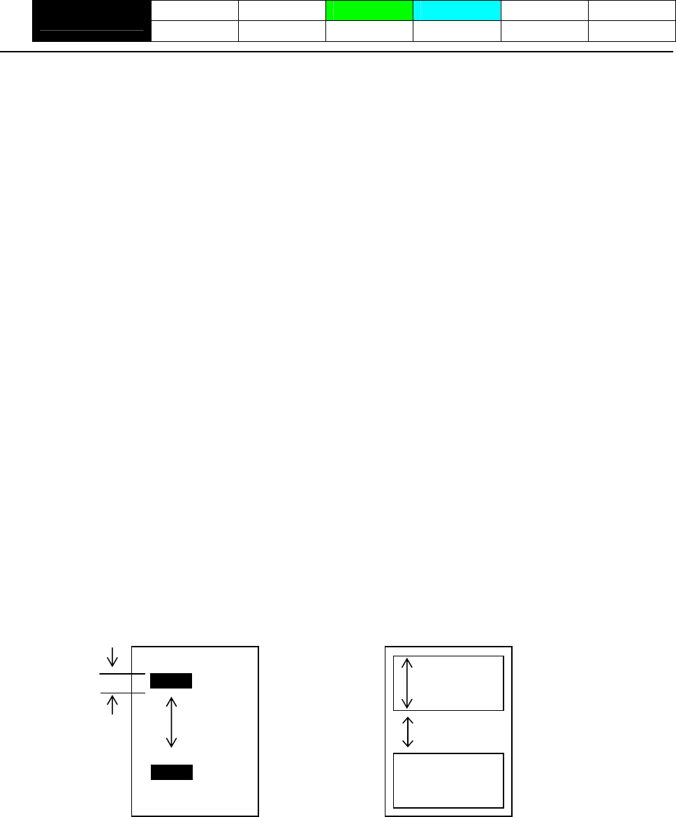
- 150 -
GS l n1L n1H n2L n2H
CT-S280 CT-S300 CT-S2000 CT-S4000 BD2-2220 CT-S310
support model PMU2XXX
[Function] Setting the Black mark/ label length
[Code] <1D>H<6C>H<n1L><n1H><n2L><n2H>
[Range] 0≦n1L≦255 (24≦n1L+n1H×256≦360)
0≦n1H≦1
8≦n2L≦30
n2H=0
[Outline] [The specification which is common to the model]
Define the specifications (length) of the Black mark/ label used.
n1: Sets the Black mark pitch/ label length
n2: Sets the Black mark length/ label gap length
n1 and n2 are specified units of millimeters.
Divide the maximum Black mark pitch/ label length by 256 with the quotient designated as n1L and
the remainder as n2H. Accordingly, the Black mark pitch/ label length available for setting will be
n1L+n2H×256.
[Caution] • If the specified length is outside of Black mark/ label specifications, the default length is set.
• 360 mm is the maximum Black mark pitch/ label length allowed to define and 24 mm is the
minimum.
• 30 mm is the maximum allowable Black mark length/ label gap length to define and 8 mm is the
minimum.
[Default] The following default values are set when memory switch SW4-1 is set to ON.
n1L=25 n1H=0 n2L=8 n2H=0
Black mark paper Label paper
n1L+n1Hx256
n2L+n2Hx256
n1L+n1Hx256
n2L+n2Hx256

- 151 -
GS p n
CT-S280 CT-S300 CT-S2000 CT-S4000 BD2-2220 CT-S310
support model PMU2XXX
[Function] Changing paper type
[Code] <1D>H <70>H
[Range] 0≦n≦255
n=0 specify receipt paper
n=1 specify black mark paper
n=2 specify label paper
[Outline] [The specification which is common to the model]
• Switches paper.
• Switches to receipt paper (mode).
Ignores this command when receipt mode is set.
• Switches to BM paper mode.
Measures paper length or sets first position of paper in accordance with the MSW setting.
Ignores this command when BM paper mode is set.
• Switches to label paper mode.
Measures paper length or sets first position of paper in accordance with the MSW setting.
Ignores this command when label paper mode is set.
[Caution] • Processed after buffering.
• This command is not initialized by the initialization command.
• This command is initialized by power OFF and paper type set by MSW is valid from the
next power ON.
• When BM paper/Label paper mode is changed to receipt mode
Change the paper to receipt paper after sending this command (n=0) with BM
paper/label paper set. If the paper is changed to receipt paper beforehand, sensing the
first position is not available when closing the cover, resulting in BM/label detection error.
• When receipt mode is changed to label mode
Send this command (n=1) after changing the paper from receipt paper to label paper.
If this command is sent beforehand, label detection error is caused.
- 152 -
2.2.16 Printer Function Setting Commands
GS ( D pL pH m [a1 b1]...[ak bk]
CT-S280 CT-S300 CT-S2000 CT-S4000 BD2-2220 CT-S310
support model PMU2XXX
[Function] Enabling or disabling real-time command
[Code] <1D>H<28>H<44>H<pL>< pH>< m> [<a1>< b1>]…[<ak>< bk>]
[Range] 3≦(pL+pH×256)≦65535
m=20
a=1
b=0、1、48、49
[Outline] [The specification which is common to the model]
Enables/disables the following real-time command processing.
Function a b
0、48 Does not process DLE DC4 fn m t (fn = 1). (Invalid)
1 1、49 Processes DLE DC4 fn m t (fn = 1). (Valid)
• pL and pH sets the number of bytes on and after m in (pL + pH x256).
• “a” sets the kind of real-time command.
• “b” sets Valid or Invalid.
• When data raw that meets the code configuring real-time command in the image data, it is
recommended that the real-time command be set to invalid by this command.
[Default]
Type of Real-time Command Initial Value
a
DLE DC4 fn m t (fn=1): Real-time output of pulse specified Valid
1
- 153 -
GS ( E pL pH fn […]
CT-S280 CT-S300 CT-S2000 CT-S4000 BD2-2220 CT-S310
support model PMU2XXX
[Function] Printer function setting command
[Outline] [The specification which is common to the model]
Printer function setting command is a command to change the function of the printer stored on the
non-volatile memory and executes the function set by the value of “fn”.
Function No.
(fn) Function
Function1 Transfers to printer function setting mode.
Function 2 Terminates printer function setting mode.
Function 3 Sets memory switch value.
Function 4 Sends memory switch value set.
Function 5 Sets customize value.
Function 6 Sends customized value set.
Function 7 Copies user-defined page.
Function 8 Defines the data in column format to the character code page of work area.
Function 9 Defines the data in raster format to the character code page of work area.
Function 10 Erases the data of character code page of work area.
Function 11 Sets the communication condition of serial interface. (Note)
Function 12 Sends the communication condition of serial interface set.
Sets all contents set in printer function setting mode to the state at the time of
shipment.
Function 255
• pL, pH set the number of bytes following “fn” to (pL + pH 256).
• At the end of printer function setting mode (Function 2), resetting is executed. Then the input
buffer is cleared to return various kinds of setting to the state at the time of power on.
• The set value can be confirmed without transferring to printer function setting mode by functions
4, 6, and 12.
• Other functions do not operate without transferring to printer function setting mode.
[Caution] • This command allows writing to non-volatile memory. Therefore, using this command frequently
may result in breakage of memory. Use this command appropriately [10 times max./day].
• During execution of this command, the printer is in Busy state and stops receiving operation.
Therefore, data transmission from the host is prohibited.
- 154 -
fn=1: Function 1 Transferring to Printer Function Setting Mode
GS ( E pL pH fn d1 d2
[Code] <1D>H<28>H<45>H <pL><pH><fn><d1><d2>
[Range] (pL+pH×256)=3 (pL=3、pH=0)
fn=1
d1=73 (“I”)
d2=78 (“N”)
[Outline] [The specification which is common to the model]
Transfers to printer function setting mode and sends the report of mode transfer.
Hex. No. of Data
Header 37H 1
ID 20H 1
NULL 00H 1
fn=2: Function 2 End of Printer Function Setting Mode
GS ( E pL pH fn d1 d2 d3
[Code] <1D>H<28>H<45>H <pL><pH><fn><d1><d2><d3>
[Range] (pL+pH×256)=4 (pL=4、pH=0)
fn=2
d1=79 (“O”)
d2=85 (“U”)
d3=84 (“T”)
[Outline] [The specification which is common to the model]
• Terminates printer function setting mode and executes resetting.
• Clears input buffer and print buffer and restores various kinds of setting to the state at power on.
• Operates only in printer function setting mode.
fn=3: Function 3 Setting Memory Switch Value
[Caution] [The specification which depend on the model]
[Outline] [The specification which is common to the model]
[Code] <1D>H<28>H<45>H<pL><pH><fn>[<a1><b18>…<b11>]…[<ak><bk8>…<bk1>]
[Range] 10≦(pL+pH×256)≦65535
GS ( E pL pH fn [a1 b18...b11]...[ak bk8...bk1]
• MSW7 to MSW10 cannot be changed by this command. They can be changed by the
setting of customize value.
CT-S2000/CT-S4000/CT-S310
• Changes the memory switch set in a to the value set in “b”.
a = 1、2、3、4、5
CT-S2000/CT-S4000/CT-S310/PMU2XXX
a=1、2、3、4
CT-S300
a=1、2、3
CT-S280/BD2-2220
b=48、49、50
fn=3
- 155 -
b Function
48 Sets corresponding bit to OFF.
49 Sets corresponding bit to ON.
50 Does not change corresponding bit.
CT-S280
• Setting memory switch 3 (a = 3) • Setting memory with 1 (a = 1)
n b (Set Value) Function n b (Set Value) Function
48 (Default) Reports the power on. 1 48 (Default) Reserve
1 49 Does not report power on. 2 48 (Default) Reserve
48 (Default) Sets input buffer capacity to 4K bytes. 48 (Default) Resets with parallel pin 31.
2 3
49 Sets input buffer capacity to 45 bytes. 49 Does not reset with parallel pin 31.
48 (Default) Sets input buffer full and offline to be Busy. 4 48 (Default) Reserve
3 49 Sets to be busy with input buffer full. 5 48 (Default) Reserve
At the occurrence of receiving error, replaces the data with
“?”.
48 (Default) 6 48 (Default) Reserve
4
49 At the occurrence of receiving error, ignores the data.
48 (Default) Disables CR (0DH).
5 49 Enables CR (0DH).
6 48 (Default) Reserved
48 (Default) Does not reset at serial I/F pin 6.
7 49 Resets at serial I/F pin 6.
8 48 (Default) Reserve
• Setting memory switch 2 (a = 2)
n b (Set Value) Function
1 49(Default) Reserve
2 48(Default) Reserve
48 (Default) Enables stored printing.
3 49 Disables stored printing.
48 (Default) Immediately after digit reaches full, line-feed is taken.
4 49 Immediately after digit reaches full, data wait is taken.
48 (Default) After cover close and PE recovery, prints as it is.
5 49
After cover close and PE recovery, prints from the
beginning using PAGE MODE, barcode, image,
double-height printing, etc. as a unit.
6 49 (Default) Reserve
7 48 (Default) Reserve
48 (Default) Enables PNE.
8 49 Disables PNE.
48 Sets CBM270-noncompatible mode. 7
49 (Default) Sets CBM270-compatible mode.
Sets cover open error during printing to be auto recovery
error.
48 (Default)
8 Sets cover open error during printing to be recoverable
error.
49
- 156 -
CT-S300 • Setting memory switch 3 (a = 3)
n b (Set Value) Function
• Setting memory with 1 (a = 1)
48 (Default) After clearing cutter error, can be restored by Feed SW.
n b (Set Value) Function 1 49 After clearing cutter error, cannot be restored by Feed SW.
48 (Default) Reports the power on.
1 When selecting cover open error as recoverable error,
recovered by cover close
49 Does not report power on. 48(Default)
48 (Default) Sets input buffer capacity to 4K bytes. 2
2 When selecting cover open error as recoverable error,
recovered by command
49 Sets input buffer capacity to 45 bytes. 49
48 (Default) Sets input buffer full and offline to be Busy.
3 48 (Default) Resets with parallel pin 31.
49 Sets to be busy with input buffer full. 3 49 Does not reset with parallel pin 31.
At the occurrence of receiving error, replaces the data with
“?”.
48 (Default) 48(Default) Uses thermal paper
4 4 49 Uses Black mark paper
49 At the occurrence of receiving error, ignores the data. 48(Default) Used with 48/32 print columns
48 (Default) Disables CR (0DH). 5
5 49 Used with 42/30 print columns
49 Enables CR (0DH).
6 48 (Default) Undefined
6 48 (Default) Reserved
48 (Default) Does not reset at serial I/F pin 6.
7 49 Resets at serial I/F pin 6.
48 (Default) Does not reset at serial I/F pin 25.
8 49 Resets sat serial I/F pin 25.
• Setting memory switch 2 (a = 2)
n b (Set Value) Function
1 49 (Default) Reserved
48 Disables auto cutter.
2 49 (Default) Enables auto cutter.
48 (Default) Enables stored printing.
3 49 Disables stored printing.
48 (Default) Immediately after digit reaches full, line-feed is taken.
4 49 Immediately after digit reaches full, data wait is taken.
48 (Default) After cover close and PE recovery, prints as it is.
5 49
After cover close and PE recovery, prints from the
beginning using PAGE MODE, barcode, image,
double-height printing, etc. as a unit.
48(Default) Sets paper width to 80 mm 6
49 Sets paper width to 58 mm
7 48(Default) Reserve
48(Default) Enables PNE.
8 49 Disables PNE.
48 Sets CBM1000-noncompatible mode. 7
49 (Default) Sets CBM11000-compatible mode.
Sets cover open error during printing to be auto recovery
error.
48 (Default)
8 Sets cover open error during printing to be recoverable
error.
49
- 157 -

CT-S300
• Setting memory switch 4 (a = 4)
n b (Set Value) Function
At the selection of Black mark paper, disables auto
end-measurement.
48 (Default)
1 At the selection of Black mark paper, enables auto
end-measurement.
49
At the selection of Black mark paper, sets sensor position
to be on the printing side
48(Default)
2 At the selection of Black mark paper, sets sensor position
to be on the back of the printing side
49
3 48 (Default) Undefined
4 48 (Default) Undefined
5 48 (Default) Undefined
6 48 (Default) Undefined
7 48 (Default) Undefined
48 (Default) Forcible partial cut disabled.
8 Forcible partial cut enabled (full cut by command:
enabled).
49
* Memory switches 4-1, -2 are valid when memory switch 3-4 is ON.
- 158 -

CT-S2000
• Setting memory with 1 (a = 1) • Setting memory switch 3 (a = 3)
n b (Set Value) Function n b (Set Value) Function
48 (Default) Reports the power on. 48 (Default) After clearing cutter error, can be restored by Feed SW.
1 1
49 Does not report power on. 49 After clearing cutter error, cannot be restored by Feed SW.
48 (Default) Sets input buffer capacity to 4K bytes. 2 48 (Default) Reserved
2 49 Sets input buffer capacity to 45 bytes. 48 (Default) Resets with parallel pin 31.
3 49 Does not reset with parallel pin 31.
48 (Default) Sets input buffer full and offline to be Busy.
3 4 48 (Default) Reserved
49 Sets to be busy with input buffer full.
5 48 (Default) Reserved
At the occurrence of receiving error, replaces the data with
“?”.
48 (Default) 6 48 (Default) Undefined
4
49 At the occurrence of receiving error, ignores the data.
48 (Default) Disables CR (0DH).
5 49 Enables CR (0DH).
6 48 (Default) Reserved
48 (Default) Does not reset at serial I/F pin 6.
7 49 Resets at serial I/F pin 6.
48 (Default) Does not reset at serial I/F pin 25.
8 49 Resets sat serial I/F pin 25.
*With MSW1-2, parallel I/F (4K fixed) and USB I/F (16K fixed) are disabled.
With serial I/F, 45 bytes are enabled only when DMA control (MSW7-6) is
disabled.
• Setting memory switch 2 (a = 2)
n b (Set Value) Function
1 49 (Default) Reserve
48 Disables auto cutter.
2 49 (Default) Enables auto cutter.
48 (Default) Enables stored printing.
3 49 Disables stored printing.
48 (Default) Immediately after digit reaches full, line-feed is taken.
4 49 Immediately after digit reaches full, data wait is taken.
48 (Default) After cover close and PE recovery, prints as it is.
5 49
After cover close and PE recovery, prints from the
beginning using PAGE MODE, barcode, image,
double-height printing, etc. as a unit.
6 48 (Default) Reserved
7 48 (Default) Reserved
48 (Default) Enables PNE.
8 49 Disables PNE.
48 (Default) Sets CBM1000-noncompatible mode. 7
49 Sets CBM11000-compatible mode.
Sets cover open error during printing to be auto recovery
error.
48 (Default)
8 Sets cover open error during printing to be recoverable
error.
49
• Setting memory switch 4 (a = 4)
n b (Set Value) Function
At the selection of Black mark paper, disables auto
end-measurement.
48 (Default)
1 At the selection of Black mark paper, enables auto
end-measurement.
49
2 48 (Default) Reserve
48 Paper heading cut disabled.
3 49 (Default) Paper heading cut enabled.
4 48 (Default) Undefined
5 48 (Default) Undefined
6 48 (Default) Undefined
7 48 (Default) Undefined
48 Forcible partial cut disabled.
8 Forcible partial cut enabled (full but by command:
enabled).
49 (Default)
- 159 -

CT-S2000
• Setting memory switch 5 (a = 5)
n B (Set Value) Function
48 (Default) Buzzer sound enabled
1 Buzzer sound disabled 49
48 (Default) Basic calculation pitch (180 dpi / 360 dpi)
2 49 Basic calculation pitch (203 dpi / 406 dpi)
48 USB mode virtual serial
3 49 (Default) USB mode printer class
48 (Default) Reserve
4
5 48 (Default) Undefined
6 48 (Default) Undefined
7 48 (Default) Undefined
8 48 (Default) Undefined
- 160 -
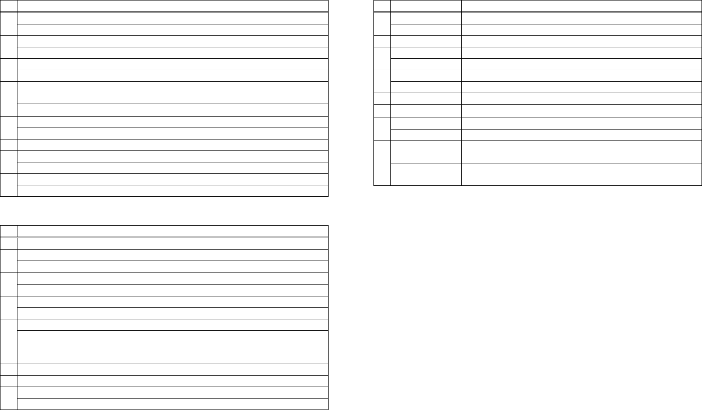
CT-S4000
• Setting memory with 1 (a = 1) • Setting memory switch 3 (a = 3)
n b (Set Value) Function n b (Set Value) Function
48 (Default) Reports the power on. 48 (Default) After clearing cutter error, can be restored by Feed SW.
1 1
49 Does not report power on. 49 After clearing cutter error, cannot be restored by Feed SW.
48 (Default) Sets input buffer capacity to 4K bytes. 2 48 (Default) Reserved
2 49 Sets input buffer capacity to 45 bytes. (Note) 48 (Default) Resets with parallel pin 31.
3
48 (Default) Sets input buffer full and offline to be Busy. 49 Does not reset with parallel pin 31.
3 49 Sets to be busy with input buffer full. 48(Default) Uses thermal paper
4
48 (Default) At the occurrence of receiving error, replaces the data with
“?”.
49 Uses Black mark paper
5 48 (Default) Reserved
4
49 At the occurrence of receiving error, ignores the data. 6 48 (Default) Undefined
48 (Default) Disables CR (0DH).
5 49 Enables CR (0DH).
6 48 (Default) Reserved
48 (Default) Does not reset at serial I/F pin 6.
7 49 Resets at serial I/F pin 6.
48 (Default) Does not reset at serial I/F pin 25.
8 49 Resets sat serial I/F pin 25.
• Setting memory switch 2 (a = 2)
n b (Set Value) Function
1 49 (Default) Reserved
48 Disables auto cutter.
2 49 (Default) Enables auto cutter.
48 (Default) Enables stored printing.
3 49 Disables stored printing.
48 (Default) Immediately after digit reaches full, line-feed is taken.
4 49 Immediately after digit reaches full, data wait is taken.
48 (Default) After cover close and PE recovery, prints as it is.
5 49
After cover close and PE recovery, prints from the
beginning using PAGE MODE, barcode, image,
double-height printing, etc. as a unit.
6 48 (Default) Reserved
7 48 (Default) Reserved
48 (Default) Enables PNE.
8 49 Disables PNE.
48 (Default) Sets CBM1000-noncompatible mode. 7
49 Sets CBM11000-compatible mode.
Sets cover open error during printing to be auto recovery
error.
48 (Default)
8 Sets cover open error during printing to be recoverable
error.
49
- 161 -

CT-S4000
• Setting memory switch 4 (a = 4) • Setting memory switch 5 (a = 5)
n b (Set Value) Function n B (Set Value) Function
48 (Default) At the selection of Black mark paper/ label paper, disables
auto end-measurement.
48 (Default) Buzzer sound enabled
1 Buzzer sound disabled 49
1
49 At the selection of Black mark paper/ label paper, enables
auto end-measurement.
48 (Default) Basic calculation pitch (180 dpi / 360 dpi)
2 49 Basic calculation pitch (203 dpi / 406 dpi)
48 (Default) Setting the first position at power ON disabled. 48 USB mode virtual serial
2 3
48 Setting the first position at power ON enabled. 49 (Default) USB mode printer class
48 Paper heading cut disabled. 4 48 (Default) Reserve
3 49 (Default) Paper heading cut enabled. 48 (Default) Reports the power off.
5
48 Uses Black mark paper/ label paper 49 Does not report power off.
4 49 (Default) Uses thermal roll paper 48 (Default) Undefined
6
48 (Default) Detects paper position and black mark. 48 (Default) Undefined
7
5 49 Detects paper position and inter-label distance. 8 48 (Default) Undefined
Reserved
6 48 (Default)
Reserved
7 48 (Default)
48 Forcible partial cut disabled.
8 Forcible partial cut enabled (full but by command:
enabled).
49 (Default)
*Initial value differs depending on the destination.
Initial value of standard model is roll paper setting.
*Only BM/label model is valid. When roll paper is specified with bit 4, this
bit is invalid.
*When BM paper/label paper is selected, this bit is invalid (full cut at all
times).
- 162 -
BD2-2220
• Setting memory with 1 (a = 1) • Setting memory switch 3 (a = 3)
n b (Set Value) Function n b (Set Value) Function
48 (Default) Reports the power on. 48 (Default) After clearing cutter error, can be restored by Feed SW.
1 1
49 Does not report power on. 49 After clearing cutter error, cannot be restored by Feed SW.
48 (Default) Sets input buffer capacity to 4K bytes. 2 48 (Default) Reserved
2 49 Sets input buffer capacity to 45 bytes. (Note) 48 (Default) Resets with parallel pin 31.
3
48 (Default) Sets input buffer full and offline to be Busy. 49 Does not reset with parallel pin 31.
3 49 Sets to be busy with input buffer full. 4 48 (Default) Reserve
At the occurrence of receiving error, replaces the data with
“?”.
48 (Default) 5 48 (Default) Reserve
4 6 48 (Default) Reserve
49 At the occurrence of receiving error, ignores the data. 7 48 (Default) Reserve
48 (Default) Disables CR (0DH). Sets head-up* error during printing to be auto recovery
error.
5 48 (Default)
49 Enables CR (0DH).
8
6 48 (Default) Reserved Sets head-up* error during printing to be recoverable
error.
49
48 (Default) Does not reset at serial I/F pin 6.
7 49 Resets at serial I/F pin 6.
8 48 (Default) Reserve * Name depends on a mechanism to use.
LT2X20 series: Head-down/Head-up
• Setting memory switch 2 (a = 2) LT2X21 series: platen-close/platen-open
n b (Set Value) Function
1 49 (Default) Reserve
2 48 (Default) Reserve
48 (Default) Enables stored printing.
3 49 Disables stored printing.
48 (Default) Immediately after digit reaches full, line-feed is taken.
4 49 Immediately after digit reaches full, data wait is taken.
48 (Default) After head-down* and PE recovery, prints as it is.
After head-down* and PE recovery, prints from the
beginning using PAGE MODE, barcode, image,
double-height printing, etc. as a unit.
5 49
6 49 (Default) Reserve
7 48 (Default) Reserve
8 48 (Default) Reserve
- 163 -
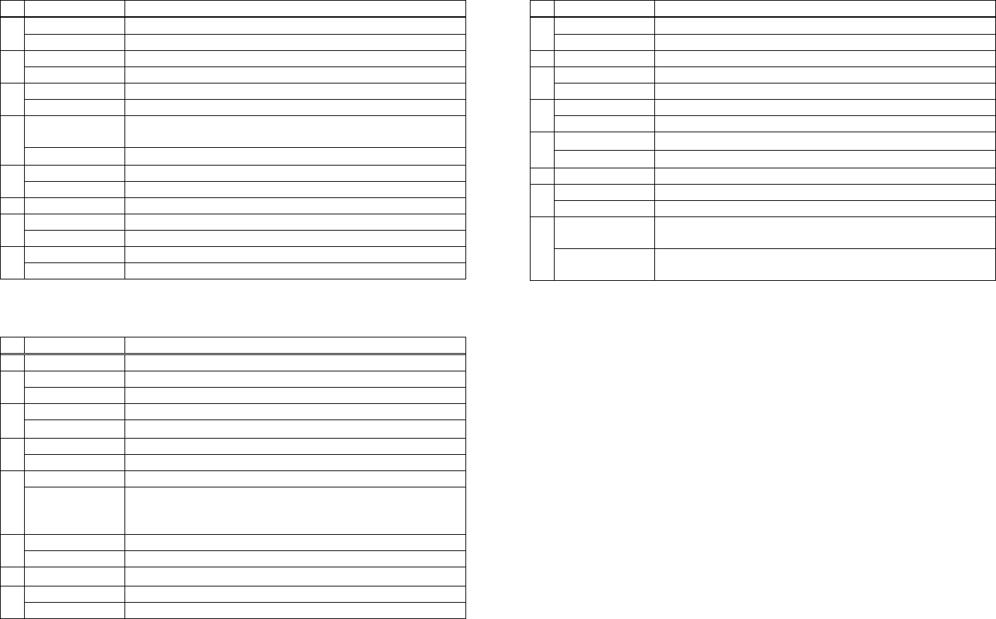
CT-S310
• Setting memory switch 3 (a = 3) • Setting memory with 1 (a = 1)
n b (Set Value) Function n b (Set Value) Function
48 (Default) Reports the power on. 48 (Default) After clearing cutter error, can be restored by Feed SW.
1 1
49 Does not report power on. 49 After clearing cutter error, cannot be restored by Feed SW.
48 (Default) Sets input buffer capacity to 4K bytes. 2 48(Default) Reserved
2 49 Sets input buffer capacity to 45 bytes. 48 (Default) Resets with parallel pin 31.
3
48 (Default) Sets input buffer full and offline to be Busy. 49 Does not reset with parallel pin 31.
3 49 Sets to be busy with input buffer full. 48(Default) Uses thermal paper
4
48 (Default) At the occurrence of receiving error, replaces the data with
“?”.
49 Uses Black mark paper
4 48(Default) Used with 48/32 print columns
5
49 At the occurrence of receiving error, ignores the data. 49 Used with 42/30 print columns
48 (Default) Disables CR (0DH). 6 48 (Default) Undefined
5 49 Enables CR (0DH).
6 48 (Default) Reserved
48 (Default) Does not reset at serial I/F pin 6.
7 49 Resets at serial I/F pin 6.
48 (Default) Does not reset at serial I/F pin 25.
8 49 Resets sat serial I/F pin 25.
*With MSW1-2, parallel I/F (4K fixed) and USB I/F (16K fixed) are disabled.
• Setting memory switch 2 (a = 2)
n b (Set Value) Function
1 49 (Default) Reserved
48 Disables auto cutter.
2 49 (Default) Enables auto cutter.
48 (Default) Enables stored printing.
3 49 Disables stored printing.
48 Immediately after digit reaches full, line-feed is taken.
4 49 (Default) Immediately after digit reaches full, data wait is taken.
48 (Default) After cover close and PE recovery, prints as it is.
5 49
After cover close and PE recovery, prints from the
beginning using PAGE MODE, barcode, image,
double-height printing, etc. as a unit.
48(Default) Sets paper width to 80 mm 6
49 Sets paper width to 58 mm
7 48(Default) Reserve
48(Default) Enables PNE.
8 49 Disables PNE.
48 (Default) Sets CBM1000-noncompatible mode. 7
49 Sets CBM11000-compatible mode.
Sets cover open error during printing to be auto recovery
error.
48 (Default)
8 Sets cover open error during printing to be recoverable
error.
49
- 164 -

CT-S310
• Setting memory switch 4 (a = 4)
n b (Set Value) Function
At the selection of Black mark paper, disables auto
end-measurement.
48 (Default)
1 At the selection of Black mark paper, enables auto
end-measurement.
49
At the selection of Black mark paper, sets sensor position
to be on the printing side
48(Default)
2 At the selection of Black mark paper, sets sensor position
to be on the back of the printing side
49
Paper heading cut disabled.
48
3 Paper heading cut enabled.
49(Default)
4 48(Default) Undefined
5 48(Default) Undefined
6 48(Default) Undefined
7 48(Default) Undefined
48 Forcible partial cut disabled.
8 Forcible partial cut enabled (full cut by command:
enabled).
49(Default)
* Memory switches 4-1, -2 are valid when memory switch 3-4 is ON.
• Setting memory switch 5 (a = 5)
n B (Set Value) Function
48 (Default) Buzzer sound enabled
1 Buzzer sound disabled 49
2 48 (Default) Reserved
48 USB mode virtual serial
3 49 (Default) USB mode printer class
4 48 (Default) Reserve
48 (Default) Reports the power off.
5 49 Does not report power off.
48 (Default) Undefined
6
48 (Default) After PNE recovery, Error LED is turned off automatically.
7 After PNE recovery, Error LED is turned on until the time
when paper is set (cover is opened).
49
8 48 (Default) Undefined
- 165 -
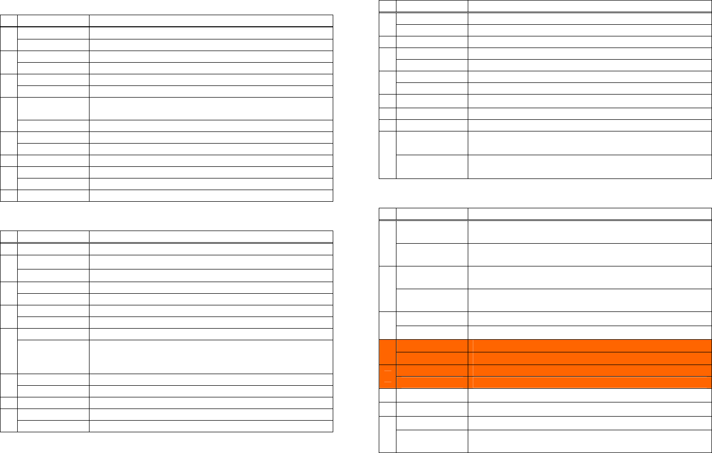
PMU2XXX • Setting memory switch 3 (a = 3)
n b (Set Value) Function
• Setting memory with 1 (a = 1)
48 (Default) After clearing cutter error, can be restored by Feed SW.
n b (Set Value) Function 1 49 After clearing cutter error, cannot be restored by Feed SW.
48 (Default) Reports the power on.
1 2 48 (Default) Reserved
49 Does not report power on. 48 (Default) Resets with parallel pin 31.
48 (Default) Sets input buffer capacity to 4K bytes. 3
2 49 Does not reset with parallel pin 31.
49 Sets input buffer capacity to 45 bytes. (Note) 48 (Default) Uses thermal paper
48 (Default) Sets input buffer full and offline to be Busy. 4
3 49 Uses Black mark paper
49 Sets to be busy with input buffer full.
5 48 (Default) Reserve
At the occurrence of receiving error, replaces the data with
“?”.
48 (Default) 6 48 (Default) Reserve
4
49 At the occurrence of receiving error, ignores the data. 7 48 (Default) Reserve
Sets platen-open error during printing to be auto
recovery error.
48 (Default) Disables CR (0DH).
5 48 (Default)
49 Enables CR (0DH). 8
6 48 (Default) Reserved Sets platen-open error during printing to be recoverable
error.
49
48 (Default) Does not reset at serial I/F pin 6.
7 49 Resets at serial I/F pin 6.
8 48 (Default) Reserve • Setting memory switch 4 (a = 4)
n b (Set Value) Function
• Setting memory switch 2 (a = 2) At the selection of Black mark paper, disables auto
end-measurement.
48
n b (Set Value) Function 1
1 49 (Default) Reserve At the selection of Black mark paper, enables auto
end-measurement.
49 (Default)
48 Disables auto cutter.
2 At the selection of Black mark paper, sets sensor position
to be on the printing side
49(Default) Enables auto cutter. 48 (Default)
48 (Default) Enables stored printing. 2
3 At the selection of Black mark paper, sets sensor position
to be on the back of the printing side
49 Disables stored printing. 49
48 (Default) Immediately after digit reaches full, line-feed is taken.
4 Paper heading cut disabled.
48
49 Immediately after digit reaches full, data wait is taken. 3 Paper heading cut enabled.
49 (Default)
48 (Default) After head-down* and PE recovery, prints as it is.
5 49
After head-down* and PE recovery, prints from the
beginning using PAGE MODE, barcode, image,
double-height printing, etc. as a unit.
Base style is PMU2XX0/PMU2XX2.
48
4
48 Sets paper width to 80 mm
6 49 Sets paper width to 58(60) mm
7 48 (Default) Reserve
48 Enables PNE.
8 49 (Default) Disables PNE.
Base style is PMU2XX1.
49
Mechanism name is LT-23XX.
48
5 Mechanism name is LT-22XX.
49
6 48 (Default) Undefined
7 48 (Default) Undefined
48(Default) Forcible partial cut disabled.
8 Forcible partial cut enabled (full cut by command:
enabled).
49
* Memory switches 4-1, -2 are valid when memory switch 3-4 is ON.
- 166 -

- 167 -
Setting memory switch 5 (a = 5)
n b (Set Value) Function
1 48 (Default) Reserved
2 48 (Default) Reserved
3 48 (Default) Reserved
4 48 (Default) Reserved
5 48 (Default) Reserved
48 It is priority of the print quqlity
6 49 (Default) Priority of the print speed
Reserved 7 48 (Default)
Reserved 8 48 (Default)
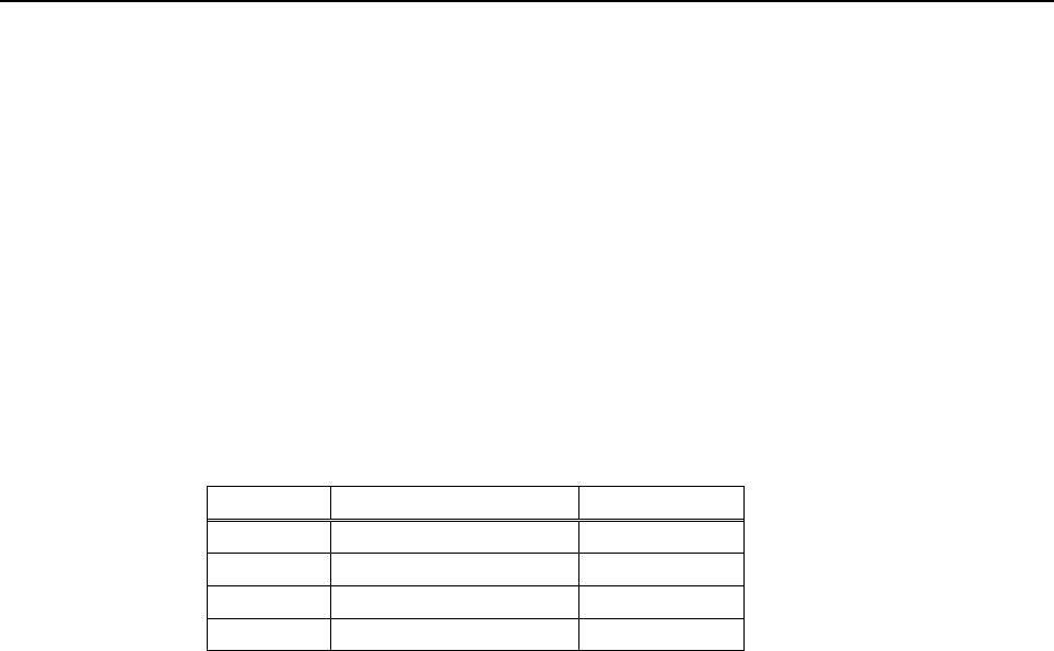
- 168 -
fn=4: Function 4 Sending the Set Memory Switch Value
GS ( E pL pH fn a
[Code] <1D>H<28>H<45>H <pL><pH><fn><a>
[Range] (pL+pH×256)=2
fn=4
CT-S280/BD2-2220
a = 1,2,3
CT-S300/PMU2XXX
a = 1,2,3,4
CT-S2000/CT-S4000/CT-S310
a = 1,2,3,4,5
[Outline] [The specification which is common to the model]
• Sends the content of memory switch set in “a”.
Hex. No. of Data
Header 37H 1
ID 21H 1
Data 30H or 31H 8
NULL 00H 1
• Sends the set value of data in 8-byte data raw in order of bits 8, 7, 6, ....
OFF: 30H (“0”)
ON : 31H (“1”)
[Caution] [The specification which depend on the model]
CT-S2000/CT-S4000/CT-S310
• MSW7 to MSW10 cannot be sent by this command.
• Transmission is available by <Sending preset customize value>.
fn=5: Function 5 Setting Customized Value
[Caution] • This function operates only in printer function setting mode.
[Outline] [The specification which is common to the model]
[Range] 4≦(pL+pH×256)≦65535
[Code] <1D>H<28>H<45>H<pL><pH><fn>[<a1><n1L><n1H>]…[<ak><nkL><nkH>]
GS ( E pL pH fn [a1 n1L n1H]...[ak nkL nkH]
1≦(nL+nH×256)≦65535
fn=5
• Sets the customized value set in “a” to (nL+nH×256).
*a=220, 221, 222, 223, 224, and 225 are supported with only label/BM model.
a=5、6、201、202、220、221、222、223、224、225
PMU2XXX
a=5、6、201、202
BD2-2220
a=1、2、3、5、6、116、201、202、212、213、214
CT-S4000
a=1、2、3、5、6、116、201、202、212、213、214、220、221、222、223、224、225
CT-S2000
a=3、5、6、97、116、201、202、220、221、222、223、224、225
CT-S300/CT-S310
a=5、6、116、201、202
CT-S280
• The value changed by this command is enabled by execution of function 2 (fn = 2: End of printer
function setting mode) (Recommended)
- 169 -
a Function
1 Specifies user NV memory capacity.
2 Specifies the memory capacity of NV graphics.
3 Selects paper width.
5 Selects printing density.
6 Selects printing speed.
97 Sets the number of divisions for conducting head
116 Selects printing color.
201 Sets ACK output position (only parallel I/F).
202 Selects input buffer full Busy output/cancel timing (idle capacity).
212 Selects DMA (Direct Memory Access) control of serial communication.
213 Selects the flow control when virtual COM is set.
214 Select the enable/disable of Kanji.
220 Sets the maximum BM width.
221 Sets the maximum BM page length.
222 Adjusts the distance of BM header.
223 Adjusts the distance of BM footer.
224 Adjusts the length of BM cut distance.
225 Adjusts the length of BM head distance.
CT-S280
• a = 5: Sets printing density to the level specified by (nL+nHx256). • a = 116: Sets the paper specified by (nL+nHx256).
(nL+nHx256) Printing Density (nL+nHx256) Paper
65530 70% 1 (Default) Specified single color paper.
65531 75% 257 Recommended 2-color paper5
65532 80%
65533 85%
65534 90%
65535 95% • a = 201: Outputs ACK to the position specified by (nL+nHx256).
0(Default) 100%
1 105% (nL+nHx256) ACK Output Position
2 110% 1 (Default) ACK-in-Busy
3 115% 2 ACK-while-Busy
4 120% 3 ACK-after-Busy
5 125%
6 130%
7 135%
8 140% • a = 202: Controls input buffer full Busy with the value selected by
(nL+nHx256) and controls Busy with output/cancel timing
(remaining capacity).
• a = 6: Sets printing speed to the value specified by (nL+nHx256).
When Input Buffer
Capacity 4K Bytes
(Large) is Set
When Input Buffer
Capacity “Small” is Set
(nL+nHx256) Printing Speed
(nL+nHx256)
Printing speed level 1 (84%) 1
2 Printing speed level 2 (86%) Output Cancel Output Cancel
1 16 26 128 256
Printing speed level 3 (88%) 3
2 16 40 128 512
Printing speed level 4 (90%) 4 3 30 50 72 256
Printing speed level 5 (92%) 5 4 30 60 72 512
6 Printing speed level 6 (94%) • XON/XOFF is also output by the establishment of conditions.
7 Printing speed level 7 (96%) • Ignores the data received when input buffer idle capacity is 0.
Printing speed level 8 (98%) 8
Printing speed level 9 (100%) 9 (Default)
- 170 -
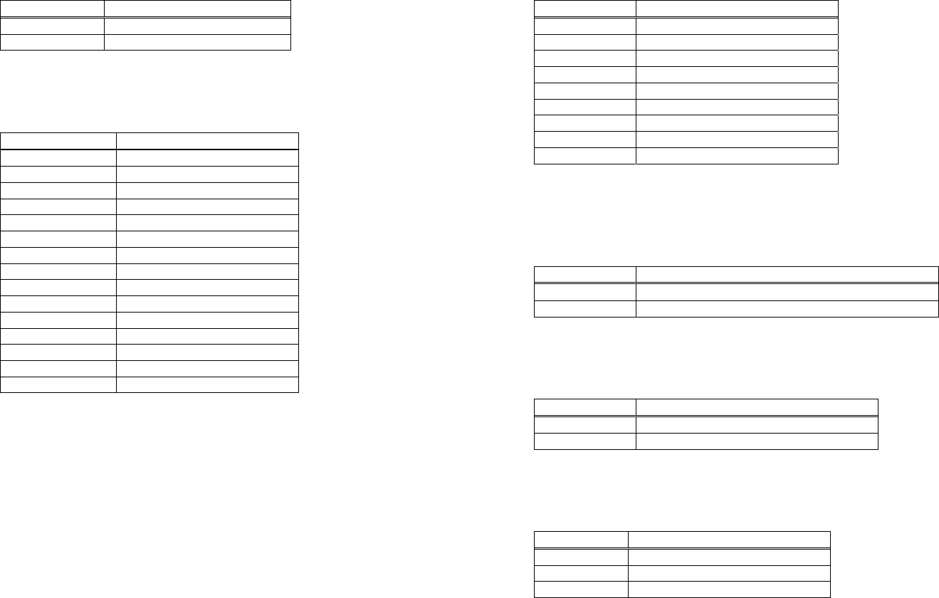
CT-S300/CT-S310
• a = 3: Sets paper width to the size specified by (nL+nHx256). • a = 6: Sets printing speed to the value specified by (nL+nHx256).
(nL+nHx256) Paper Width (nL+nHx256) Printing Speed
2 58mm Printing speed level 1 (84%) 1
6 (Default) 80mm Printing speed level 2 (86%) 2
Printing speed level 3 (88%) 3
Printing speed level 4 (90%) 4
Printing speed level 5 (92%) 5
• a = 5: Sets printing density to the level specified by (nL+nHx256). Printing speed level 6 (94%) 6
Printing speed level 7 (96%) 7
Printing speed level 8 (98%) 8
(nL+nHx256) Printing Density
Printing speed level 9 (100%) 9(Default)
65530 70%
65531 75%
65532 80%
65533 85% • a = 97: Sets the number of divisions for conducting head specified by
(nL+nH×256).
65534 90%
65535 95%
0(Default) 100%
1 105% (nL+nHx256) No. of Divisions for Conducting Head
2 110% 2(Default) 2-division conducting
3 115% 4 2-division conducting
4 120%
5 125%
6 130%
• a = 116: Sets the paper specified by (nL+nHx256). 7 135%
8 140%
(nL+nHx256) Paper
1 (Default) Specified single color paper.
257 Recommended 2-color paper5
• a = 201: Outputs ACK to the position specified by (nL+nH x256).
ACK Output Position (nL+nHx256)
1 (Default) ACK-in-Busy
2 ACK-while-Busy
3 ACK-after-Busy
- 171 -
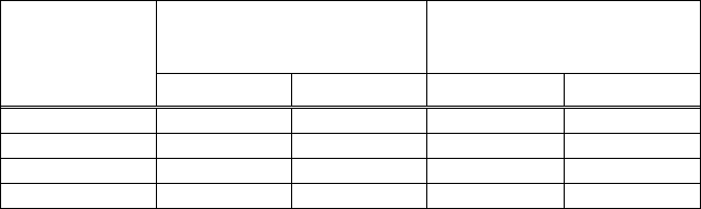
CT-S300/CT-S310
• a=222: Head margin set by the value selected by (nL+nHx256). • a = 202: Controls input buffer full Busy with the value selected by
(nL+nHx256) and controls Busy with output/cancel timing
(remaining capacity).
1≦(nL+nH×256)≦32767
Unit: 168dot
When Input Buffer
Capacity 4K Bytes
(Large) is Set
When Input Buffer
Capacity “Small” is Set
Initial value: 0dot
(nL+nHx256)
Output Cancel Output Cancel • a=223: Sets black mark bottom margin with the amount selected by
(nL+nHx256).
1 16 26 128 256
2 16 40 128 512
3 30 50 72 256
4 30 60 72 512
1≦(nL+nH×256)≦255
• XON/XOFF is also output by the establishment of conditions. Unit: 1 dot
• Ignores the data received when input buffer idle capacity is 0. Initial value: 34 dots
• a=220: Sets the maximum width of black mark by the amount selected by
(nL+nHx256).
• a=224: Sets cut distance with the value selected by (nL+nHx256).
1≦(nL+nH×256)≦255
1≦(nL+nH×256)≦32767 Unit: 1 dot
Unit: 1 dot Initial value: 232 dots
Initial value: 40 dots
• a=225: Sets head distance with the value selected by (nL+nHx256).
• a=221: Sets the maximum length of black mark page with the value
selected by (nL+nHx256).
1≦(nL+nH×256)≦255
Unit: 1 dot
1≦(nL+nH×256)≦32767 Initial value: 56 dots
Unit: 1 dot
Initial value: 2360 dots
- 172 -
CT-S2000
• a = 1: Sets the user NV memory capacity to the size specified by
(nL+nH×256).
• a = 5: Sets printing density to the level specified by (nL+nHx256).
(nL+nHx256) Printing Density
65530 70%
(nL+nHx256) Memory Capacity
65531 75%
1K bytes 1 65532 80%
2 64K bytes 65533 85%
3 128K bytes 65534 90%
4(Default) 192K bytes 65535 95%
0 (Default) 100%
1 105%
• a = 2: Sets NV graphic memory capacity to the size specified by
(nL+nHx256).
2 110%
3 115%
4 120%
5 125%
(nL+nHx256) Memory Capacity 6 130%
1 None 7 135%
2 64K bytes 8 140%
3 128K bytes
4 192K bytes
5 256K bytes
6 320K bytes • a = 6: Sets printing speed to the value specified by (nL+nHx256).
384K bytes 7 (Default)
(nL+nHx256) Printing Speed
Printing speed level 1 (84%) 1
Printing speed level 2 (86%) 2
• a = 3: Sets paper width to the size specified by (nL+nHx256).
Printing speed level 3 (88%) 3
Printing speed level 4 (90%) 4
(nL+nHx256) Paper Width Printing speed level 5 (92%) 5
1 58mm(360dot) Printing speed level 6 (94%) 6
2 58mm(384dot) Printing speed level 7 (96%) 7
3 58mm(432dot) Printing speed level 8 (98%) 8
4 58mm(432dot) Printing speed level 9 (100%) 9 (Default)
5 58mm(436dot)
6 80mm(512dot)
7 (Default) 80mm(576dot)
8 82.5mm(640dot)
- 173 -
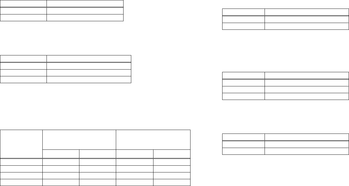
CT-S2000
• a=212: Selects DMA (Direct Memory Access) control of serial
communication specified by (nL+nHx256).
• a = 116: Sets the paper specified by (nL+nHx256).
(nL + nH x256) Paper
1 (Default) Specified single color paper. (nL+nHx256) DMA control
257 Recommended 2-color paper5 1 Invalid
2 (Default) Valid
• a = 201: Outputs ACK to the position specified by (nL+nHx256).
• a=213: Selects the flow control specified by (nL+nHx256) when virtual
COM is set.
(nL+nHx256) ACK Output Position
1 (Default) ACK-in-Busy
2 ACK-while-Busy (nL+nHx256) Flow control
3 ACK-after-Busy 1 (Default) PC setting
2 DTR/DSR
3 XON/XOFF
• a = 202: Controls input buffer full Busy with the value selected by
(nL+nHx256) and controls Busy with output/cancel timing
(remaining capacity).
• a=214: Select the enable/disable of Kanji specified by (nL+nHx256).
When Input Buffer
Capacity 4K Bytes
(Large) is Set
When Input Buffer
Capacity “Small” is Set
(nL+nHx256) Kanji
(nL+nHx256) 1 Valid(ON)
2 (Default) Invalid(OFF)
Output Cancel Output Cancel
1 16 26 128 256
2 16 40 128 512
3 30 50 72 256 • a=220: Sets the maximum width of black mark by the amount selected by
(nL+nHx256).
4 30 60 72 512
• XON/XOFF is also output by the establishment of conditions.
• Ignores the data received when input buffer idle capacity is 0. 1≦(nL+nH×256)≦32767
Unit: 1 dot
Initial value: 40 dots
- 174 -
CT-S2000
• a=221: Sets the maximum length of black mark page with the value
selected by (nL+nHx256).
• a=225: Sets head distance with the value selected by (nL+nHx256).
1≦(nL+nH×256)≦255
1≦(nL+nH×256)≦32767 Unit: 1 dot
Unit: 1 dot Initial value: 56 dots
Initial value: 2360 dots
• a=222: Head margin set by the value selected by (nL+nHx256).
1≦(nL+nH×256)≦32767
Unit: 168dot
Initial value: 0dot
• a=223: Sets black mark bottom margin with the amount selected by
(nL+nHx256).
1≦(nL+nH×256)≦255
Unit: 1 dot
Initial value: 34 dots
• a=224: Sets cut distance with the value selected by (nL+nHx256).
1≦(nL+nH×256)≦255
Unit: 1 dot
Initial value: 232 dots
- 175 -
CT-S4000
• a = 1: Sets the user NV memory capacity to the size specified by
(nL+nH×256).
• a = 5: Sets printing density to the level specified by (nL+nHx256).
(nL+nHx256) Printing Density
65530 70%
(nL+nHx256) Memory Capacity
65531 75%
1 1K bytes 65532 80%
2 64K bytes 65533 85%
3 128K bytes 65534 90%
4 192K bytes 65535 95%
0 (Default) 100%
1 105%
• a = 2: Sets NV graphic memory capacity to the size specified by
(nL+nHx256).
2 110%
3 115%
4 120%
5 125%
(nL+nHx256) Memory Capacity
6 130%
1 None
7 135%
2 64K bytes
8 140%
3 128K bytes
4 192K bytes
5 256K bytes
6 320K bytes • a = 6: Sets printing speed to the value specified by (nL+nHx256).
384K bytes 7 (Default)
(nL+nHx256) Printing Speed
Printing speed level 1 (84%) 1
• a = 3: Sets paper width to the size specified by (nL+nHx256). Printing speed level 2 (86%) 2
Printing speed level 3 (88%) 3
Printing speed level 4 (90%) 4
(nL+nHx256) Paper Width
Printing speed level 5 (92%) 5
5 512 dots
Printing speed level 6 (94%) 6
6 576 dots
Printing speed level 7 (96%) 7
7 660 dots
Printing speed level 8 (98%) 8
8 720 dots 9 (Default) Printing speed level 9 (100%)
9 (Default) 832 dots
- 176 -
CT-S4000
• a=212: Selects DMA (Direct Memory Access) control of serial
communication specified by (nL+nHx256).
• a = 116: Sets the paper specified by (nL+nHx256).
(nL+nHx256) Paper
1 (Default) Specified single color paper. (nL+nHx256) DMA control
257 Recommended 2-color paper5 1 Invalid
2 (Default) Valid
• a = 201: Outputs ACK to the position specified by (nL+nHx256).
• a=213: Selects the flow control specified by (nL+nHx256) when virtual
COM is set.
(nL+nHx256) ACK Output Position
1 (Default) ACK-in-Busy
2 ACK-while-Busy (nL+nHx256) Flow control
3 ACK-after-Busy 1 (Default) PC setting
2 DTR/DSR
3 XON/XOFF
• a = 202: Controls input buffer full Busy with the value selected by
(nL+nHx256) and controls Busy with output/cancel timing
(remaining capacity).
• a=214: Select the enable/disable of Kanji specified by (nL+nHx256).
When Input Buffer
Capacity “Small” is Set
When Input Buffer
Capacity 4K Bytes
(Large) is Set
(nL+nHx256) Kanji
1 Valid(ON)
(nL+nHx256) 2 (Default) Invalid(OFF)
Output Cancel Output Cancel
1 16 26 128 256
2 16 40 128 512
3 30 50 72 256
4 30 60 72 512
• XON/XOFF is also output by the establishment of conditions.
• Ignores the data received when input buffer idle capacity is 0.
- 177 -

BD2-2220
• a = 201: Outputs ACK to the position specified by (nL+nHx256). • a = 5: Sets printing density to the level specified by (nL+nHx256).
(nL+nHx256) Printing Density (nL+nHx256) ACK Output Position
65530 70% 1 (Default) ACK-in-Busy
2 ACK-while-Busy
65531 75% 3 ACK-after-Busy
65532 80%
65533 85%
65534 90%
65535 95% • a = 202: Controls input buffer full Busy with the value selected by
(nL+nHx256) and controls Busy with output/cancel timing
(remaining capacity).
0 (Default) 100%
1 105%
2 110%
3 115% When Input Buffer
Capacity 4K Bytes
(Large) is Set
When Input Buffer
Capacity “Small” is Set
4 120%
(nL+nHx256)
5 125%
6 130% Output Cancel Output Cancel
7 135% 1 16 26 128 256
8 140% 2 16 40 128 512
3 30 50 72 256
4 30 60 72 512
• XON/XOFF is also output by the establishment of conditions.
• a = 6: Sets printing speed to the value specified by (nL+nHx256).
• Ignores the data received when input buffer idle capacity is 0.
(nL+nHx256) Printing Speed
Printing speed level 1 (84%) 1
Printing speed level 2 (86%) 2
Printing speed level 3 (88%) 3
Printing speed level 4 (90%) 4
Printing speed level 5 (92%) 5
Printing speed level 6 (94%) 6
Printing speed level 7 (96%) 7
Printing speed level 8 (98%) 8
Printing speed level 9 (100%) 9 (Default)
- 178 -

PMU2XXX
• a = 201: Outputs ACK to the position specified by (nL+nHx256). • a = 5: Sets printing density to the level specified by (nL+nHx256).
(nL+nHx256) Printing Density (nL+nHx256) ACK Output Position
65530 70% 1 (Default) ACK-in-Busy
2 ACK-while-Busy
65531 75% 3 ACK-after-Busy
65532 80%
65533 85%
65534 90%
65535 95% • a = 202: Controls input buffer full Busy with the value selected by
(nL+nHx256) and controls Busy with output/cancel timing
(remaining capacity).
0 (Default) 100%
1 105%
2 110%
3 115% When Input Buffer
Capacity 4K Bytes
(Large) is Set
When Input Buffer
Capacity “Small” is Set
4 120%
(nL+nHx256)
5 125%
6 130% Output Cancel Output Cancel
7 135% 1 16 26 128 256
8 140% 2 16 40 128 512
3 30 50 72 256
4 30 60 72 512
• XON/XOFF is also output by the establishment of conditions.
• a = 6: Sets printing speed to the value specified by (nL+nHx256).
• Ignores the data received when input buffer idle capacity is 0.
(nL+nHx256) Printing Speed
Printing speed level 1 (84%) 1
Printing speed level 2 (86%) 2 • a=220: Sets the maximum width of black mark by the amount selected by
(nL+nHx256).
Printing speed level 3 (88%) 3
Printing speed level 4 (90%) 4
Printing speed level 5 (92%) 5
6 Printing speed level 6 (94%) 1≦(nL+nH×256)≦32767
Printing speed level 7 (96%) 7 Unit: 1 dot
Printing speed level 8 (98%) 8 Initial value: 40 dots
Printing speed level 9 (100%) 9 (Default)
- 179 -
• a=225: Sets head distance with the value selected by (nL+nHx256).
1≦(nL+nH×256)≦255
Initial value: 56 dots
Unit: 1 dot
- 180 -
• a=223: Sets black mark bottom margin with the amount selected by
(nL+nHx256).
• a=221: Sets the maximum length of black mark page with the value
selected by (nL+nHx256).
• a=224: Sets cut distance with the value selected by (nL+nHx256).
• a=222: Head margin set by the value selected by (nL+nHx256).
1≦(nL+nH×256)≦32767
1≦(nL+nH×256)≦32767
1≦(nL+nH×256)≦255
1≦(nL+nH×256)≦255
Initial value: 2360 dots
Initial value: 232 dots
Initial value: 34 dots
Initial value: 0dot
Unit: 168dot
Unit: 1 dot
Unit: 1 dot
Unit: 1 dot
PMU2XXX
fn=6: Function 6 Sending the Set Customized Value
[Range] (pL+pH×256)=2:(pL=2、pH=0)
[Code] <1D>H<28>H<45>H<pL><pH><fn><a>
[Outline] [The specification which is common to the model]
GS ( E pL pH fn a
fn=6
• Configuration of customized value No.
• Sends the set value of customized value set by “a”.
a=5、6、201、202、220、221、222、223、224、225
PMU2XXX
a=5、6、201、202
BD2-2220
a=1、2、3、5、6、116、201、202、212、213、214
CT-S4000
a=1、2、3、5、6、116、201、202、212、213、214、220、221、222、223、224、225
CT-S2000
a=3、5、6、97、116、201、202、220、221、222、223、224、225
CT-S300/CT-S310
a=5、6、116、201、202
CT-S280
- 181 -
Hex. No. of Data
Header 37H 1
ID 27H 1
Customized value No. 30H~39H 1~3
Separation number 1FH 1
Customized value 30H~39H 1~5
NULL 00H 1
Sending Data
a 1st Byte 2nd Byte 3rd Byte
1 49(“1”) ― ―
2 50(“2”) ― ―
3 51(“3”) ― ―
5 53(“5”) ― ―
6 54(“6”) ― ―
97 57(“9”) 55(“7”) ―
116 49(“1”) 49(“1”) 54(“6”)
201 50(“2”) 48(“0”) 49(“1”)
202 50(“2”) 48(“0”) 50(“2”)
212 50(“2”) 49(“1”) 50(“2”)
213 50(“2”) 49(“1”) 51(“3”)
214 50(“2”) 49(“1”) 52(“4”)
220 50(“2”) 50(“2”) 48(“0”)
221 50(“2”) 50(“2”) 49(“1”)
222 50(“2”) 50(“2”) 50(“2”)
223 50(“2”) 50(“2”) 51(“3”)
224 50(“2”) 50(“2”) 52(“4”)
225 50(“2”) 50(“2”) 53(“5”)

- 182 -
CT-S280
• a = 5: When print density is specified
Setting Status Sending Data
Stored
Value Print Density 1st Byte 2nd Byte 3rd Byte 4th Byte 5th Byte
65530 70% 54(“6”) 53(“5”) 53(“5”) 51(“3”) 48(“0”)
65531 75% 54(“6”) 53(“5”) 53(“5”) 51(“3”) 49(“1”)
65532 80% 54(“6”) 53(“5”) 53(“5”) 51(“3”) 50(“2”)
65533 85% 54(“6”) 53(“5”) 53(“5”) 51(“3”) 51(“3”)
65534 90% 54(“6”) 53(“5”) 53(“5”) 51(“3”) 52(“4”)
65535 95% 54(“6”) 53(“5”) 53(“5”) 51(“3”) 53(“5”)
0 Basic density 48(“0”) ― ― ― ―
1 105% 49(“1”) ― ― ― ―
2 110% 50(“2”) ― ― ― ―
3 115% 51(“3”) ― ― ― ―
4 120% 52(“4”) ― ― ― ―
5 125% 53(“5”) ― ― ― ―
6 130% 54(“6”) ― ― ― ―
7 135% 55(“7”) ― ― ― ―
8 140% 56(“8”) ― ― ― ―
• a = 6: When printing speed is specified
Setting Status Sending Data
Stored
Value Print Density 1st Byte 2nd Byte 3rd Byte 4th Byte 5th Byte
1 Speed level 1 49(“1”) ― ― ― ―
2 Speed level 2 50(“2”) ― ― ― ―
3 Speed level 3 51(“3”) ― ― ― ―
4 Speed level 4 52(“4”) ― ― ― ―
5 Speed level 5 53(“5”) ― ― ― ―
6 Speed level 6 54(“6”) ― ― ― ―
7 Speed level 7 55(“7”) ― ― ― ―
8 Speed level 8 56(“8”) ― ― ― ―
9 Speed level 9 57(“9”)
• a = 116: When kind of paper is specified
Setting Status Sending Data
Stored
Value Print Control 1st Byte 2nd Byte 3rd Byte 4th Byte 5th Byte
1 Single-color
paper 49(“1”) ― ― ― ―
2 2-color paper 50(“2”) ― ― ― ―
• a = 201: When ACK output position is specified
Setting Status Sending Data
Stored
Value
ACK Output
Position 1st Byte 2nd Byte 3rd Byte 4th Byte 5th Byte
1 ACK-in-Busy 49(“1”) ― ― ― ―
2 ACK-while-Busy 50(“2”) ― ― ― ―
3 ACK-after-Busy 51(“3”) ― ― ― ―
• a = 202: Input buffer full Busy output/cancel timing
Setting Status Sending Data
Stored
Value
BUSY
Output/Cancel 1st Byte 2nd Byte 3rd Byte 4th Byte 5th Byte
1 49(“1”) ― ― ― ―
2 50(“2”) ― ― ― ―
3 51(“3”) ― ― ― ―
4 52(“4”)
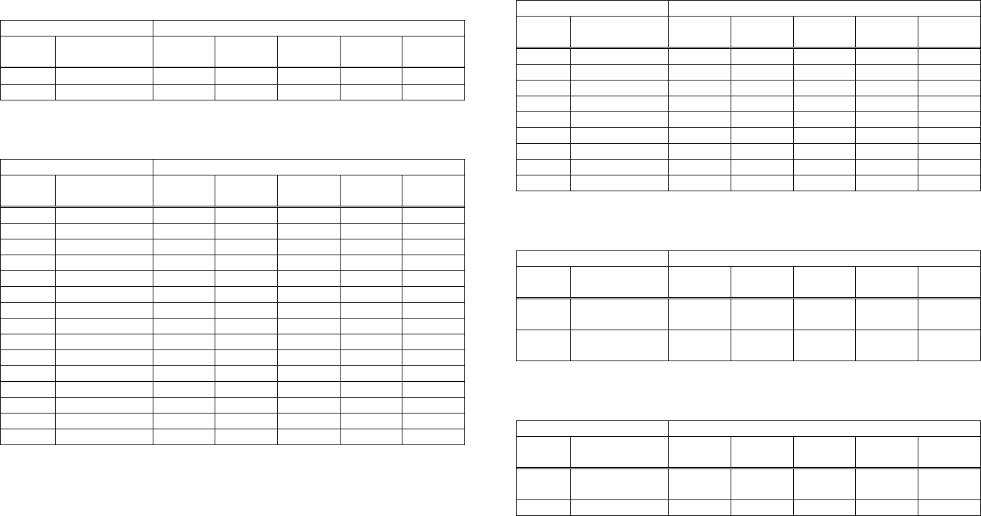
- 183 -
CT-S300/CT-S310
• a = 3: When paper width is specified
Setting Status Sending Data
Stored
Value Paper Width 1st Byte 2nd Byte 3rd Byte 4th Byte 5th Byte
1 58mm 49(“1”) ― ― ― ―
3 80mm 51(“3”) ― ― ― ―
• a = 5: When print density is specified
Setting Status Sending Data
Stored
Value Print Density 1st Byte 2nd Byte 3rd Byte 4th Byte 5th Byte
65530 70% 54(“6”) 53(“5”) 53(“5”) 51(“3”) 48(“0”)
65531 75% 54(“6”) 53(“5”) 53(“5”) 51(“3”) 49(“1”)
65532 80% 54(“6”) 53(“5”) 53(“5”) 51(“3”) 50(“2”)
65533 85% 54(“6”) 53(“5”) 53(“5”) 51(“3”) 51(“3”)
65534 90% 54(“6”) 53(“5”) 53(“5”) 51(“3”) 52(“4”)
65535 95% 54(“6”) 53(“5”) 53(“5”) 51(“3”) 53(“5”)
0 Basic density 48(“0”) ― ― ― ―
1 105% 49(“1”) ― ― ― ―
2 110% 50(“2”) ― ― ― ―
3 115% 51(“3”) ― ― ― ―
4 120% 52(“4”) ― ― ― ―
5 125% 53(“5”) ― ― ― ―
6 130% 54(“6”) ― ― ― ―
7 135% 55(“7”) ― ― ― ―
8 140% 56(“8”) ― ― ― ―
• a = 6: When printing speed is specified
Setting Status Sending Data
Stored
Value Print Speed 1st Byte 2nd Byte 3rd Byte 4th Byte 5th Byte
1 Speed level 1 49(“1”) ― ― ― ―
2 Speed level 2 50(“2”) ― ― ― ―
3 Speed level 3 51(“3”) ― ― ― ―
4 Speed level 4 52(“4”) ― ― ― ―
5 Speed level 5 53(“5”) ― ― ― ―
6 Speed level 6 54(“6”) ― ― ― ―
7 Speed level 7 55(“7”) ― ― ― ―
8 Speed level 8 56(“8”) ― ― ― ―
9 Speed level 9 57(“9”)
• a = 97: When number of divisions for head conducting is specified
Setting Status Sending Data
Stored
Value
No. of
Divisions 1st Byte 2nd Byte 3rd Byte 4th Byte 5th Byte
2 2 division
conducting 50(“2”) ― ― ― ―
4 4 division
conducting 52(“4”) ― ― ― ―
• a = 116: When kind of paper is specified
Setting Status Sending Data
Stored
Value Print Control 1st Byte 2nd Byte 3rd Byte 4th Byte 5th Byte
1 Single-color
paper 49(“1”) ― ― ― ―
2 2-color paper 50(“2”) ― ― ― ―
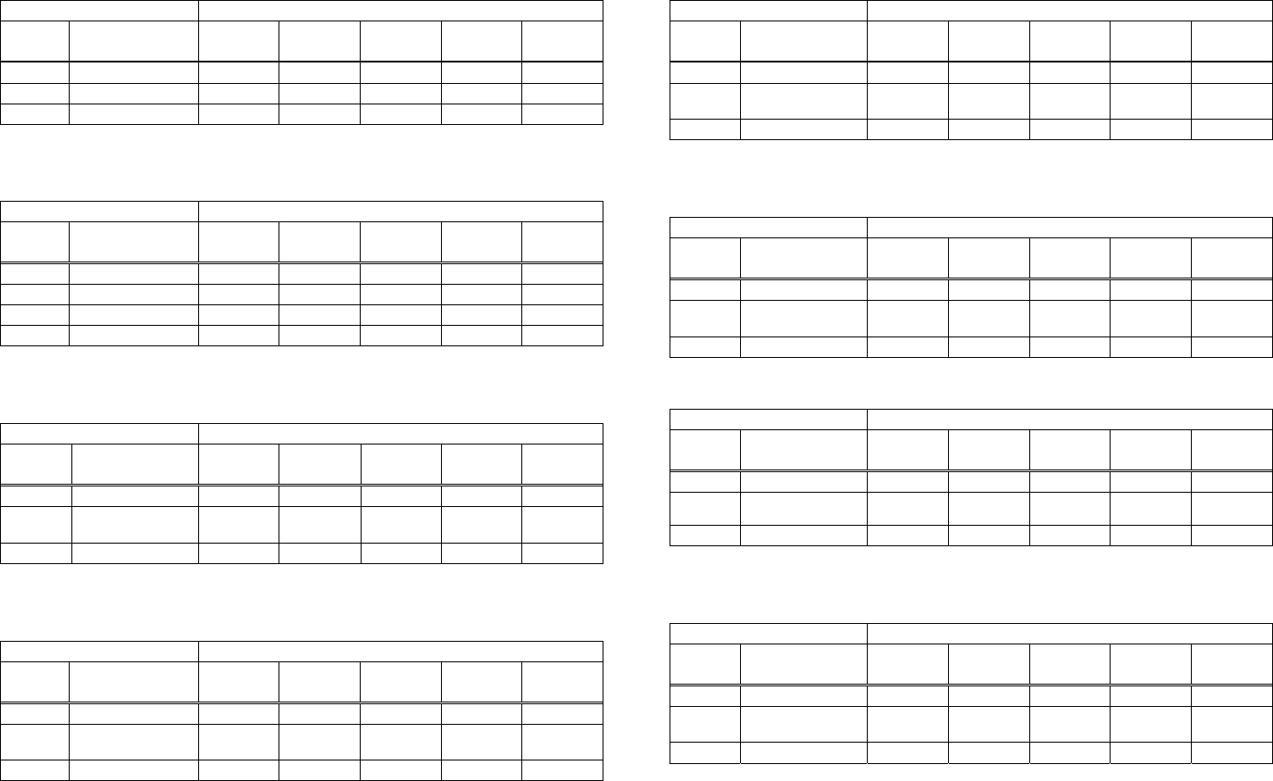
- 184 -
CT-S300/CT-S310
• a = 201: When ACK output position is specified
Setting Status Sending Data
Stored
Value
ACK Output
Position 1st Byte 2nd Byte 3rd Byte 4th Byte 5th Byte
1 ACK-in-Busy 49(“1”) ― ― ― ―
2 ACK-while-Busy 50(“2”) ― ― ― ―
3 ACK-after-Busy 51(“3”) ― ― ― ―
• a = 202: Input buffer full Busy output/cancel timing
Setting Status Sending Data
Stored
Value
BUSY
Output/Cancel 1st Byte 2nd Byte 3rd Byte 4th Byte 5th Byte
1 49(“1”) ― ― ― ―
2 50(“2”) ― ― ― ―
3 51(“3”) ― ― ― ―
4 52(“4”)
• a=220: When maximum black mark width is specified
Setting Status Sending Data
Stored
Value
Maximum B.M
Width 1st Byte 2nd Byte 3rd Byte 4th Byte 5th Byte
0 0dot 49(“1”) 48(“0”) 48(“0”) 48(“0”) 48(“0”)
・
・
・
・
・
・
・
・
・
・
・
・
・
・
・
・
・
・
・
・
・
32767 32767dot 51(“3”) 50(“2”) 55(“7”) 54(“6”) 55(“7”)
• a=221: When maximum length of black mark page is specified
Setting Status Sending Data
Stored
Value
Maximum B.M
Page Length 1st Byte 2nd Byte 3rd Byte 4th Byte 5th Byte
0 0dot 49(“1”) 48(“0”) 48(“0”) 48(“0”) 48(“0”)
・
・
・
・
・
・
・
・
・
・
・
・
・
・
・
・
・
・
・
・
・
32767 32767dot 51(“3”) 50(“2”) 55(“7”) 54(“6”) 55(“7”)
• a=222: When head margin is specified
Setting Status Sending Data
Stored
Value Head Margin 1st Byte 2nd Byte 3rd Byte 4th Byte 5th Byte
0 0dot 49(“1”) 48(“0”) 48(“0”) 48(“0”) 48(“0”)
・
・
・
・
・
・
・
・
・
・
・
・
・
・
・
・
・
・
・
・
・
32767 32767dot 51(“3”) 50(“2”) 55(“7”) 54(“6”) 55(“7”)
• a=223: When bottom margin is specified
Setting Status Sending Data
Stored
Value
Bottom
Margin 1st Byte 2nd Byte 3rd Byte 4th Byte 5th Byte
0 0 48(“0”) 48(“0”) 48(“0”) ― ―
・
・
・
・
・
・
・
・
・
・
・
・
・
・
・
・
・
・
・
・
・
255 255 50(“2”) 53(“5”) 53(“5”) ― ―
• a=224: When cut distance is specified
Setting Status Sending Data
Stored
Value Cut Distance 1st Byte 2nd Byte 3rd Byte 4th Byte 5th Byte
0 0 48(“0”) 48(“0”) 48(“0”) ― ―
・
・
・
・
・
・
・
・
・
・
・
・
・
・
・
・
・
・
・
・
・
255 255 50(“2”) 53(“5”) 53(“5”) ― ―
• a=225: When head distance is specified
Setting Status Sending Data
Stored
Value
Head
Distance 1st Byte 2nd Byte 3rd Byte 4th Byte 5th Byte
0 0 48(“0”) 48(“0”) 48(“0”) ― ―
・
・
・
・
・
・
・
・
・
・
・
・
・
・
・
・
・
・
・
・
・
255 255 50(“2”) 53(“5”) 53(“5”) ― ―
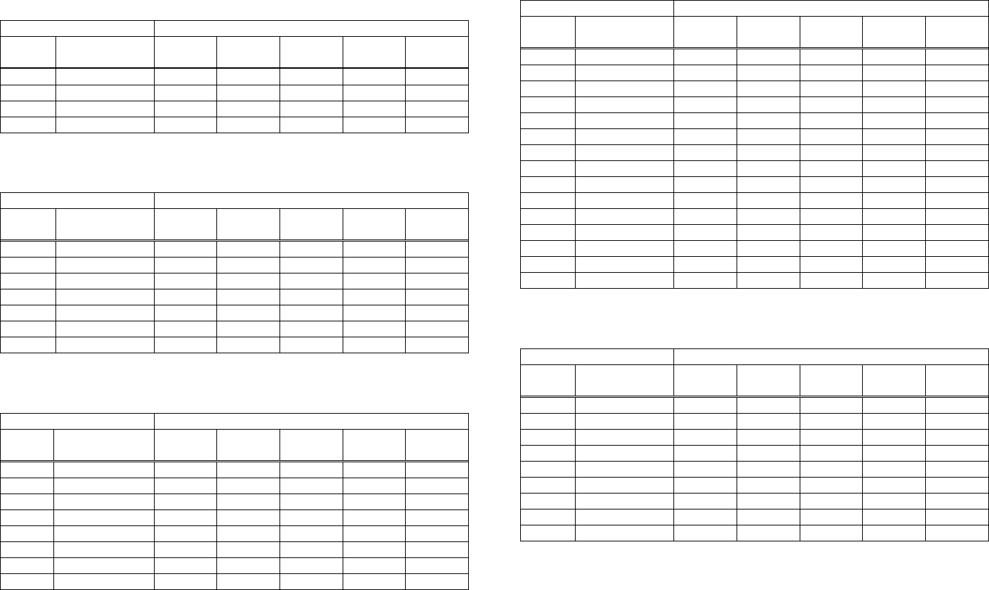
- 185 -
CT-S2000
• a = 1: When user NV memory capacity is specified
Setting Status Sending Data
Stored
Value
Memory
Capacity 1st Byte 2nd Byte 3rd Byte 4th Byte 5th Byte
1 1K bytes 49(“1”) ― ― ― ―
2 64K bytes 50(“2”) ― ― ― ―
3 128K bytes 51(“3”) ― ― ― ―
4 192K bytes 52(“4”) ― ― ― ―
• a = 2: When NV graphics memory capacity is specified
Setting Status Sending Data
Stored
Value
Memory
Capacity 1st Byte 2nd Byte 3rd Byte 4th Byte 5th Byte
1 None 49(“1”) ― ― ― ―
2 64K bytes 50(“2”) ― ― ― ―
3 128K bytes 51(“3”) ― ― ― ―
4 192K bytes 52(“4”) ― ― ― ―
5 256K bytes 53(“5”)
6 320K bytes 54(“6”)
7 384K bytes 55(“7”)
• a = 3: When paper width is specified
Setting Status Sending Data
Stored
Value Paper Width 1st Byte 2nd Byte 3rd Byte 4th Byte 5th Byte
1 58mm(360dot) 49(“1”) ― ― ― ―
2 58mm(384dot) 50(“2”) ― ― ― ―
3 58mm(432dot) 51(“3”) ― ― ― ―
4 58mm(432dot) 52(“4”) ― ― ― ―
5 58mm(436dot) 53(“5”) ― ― ― ―
6 80mm(512dot) 54(“6”) ― ― ― ―
7 80mm(576dot) 55(“7”) ― ― ― ―
8 82.5mm(640dot) 56(“8”) ― ― ― ―
• a = 5: When print density is specified
Setting Status Sending Data
Stored
Value Print Density 1st Byte 2nd Byte 3rd Byte 4th Byte 5th Byte
65530 70% 54(“6”) 53(“5”) 53(“5”) 51(“3”) 48(“0”)
65531 75% 54(“6”) 53(“5”) 53(“5”) 51(“3”) 49(“1”)
65532 80% 54(“6”) 53(“5”) 53(“5”) 51(“3”) 50(“2”)
65533 85% 54(“6”) 53(“5”) 53(“5”) 51(“3”) 51(“3”)
65534 90% 54(“6”) 53(“5”) 53(“5”) 51(“3”) 52(“4”)
65535 95% 54(“6”) 53(“5”) 53(“5”) 51(“3”) 53(“5”)
0 Basic density 48(“0”) ― ― ― ―
1 105% 49(“1”) ― ― ― ―
2 110% 50(“2”) ― ― ― ―
3 115% 51(“3”) ― ― ― ―
4 120% 52(“4”) ― ― ― ―
5 125% 53(“5”) ― ― ― ―
6 130% 54(“6”) ― ― ― ―
7 135% 55(“7”) ― ― ― ―
8 140% 56(“8”) ― ― ― ―
• a = 6: When printing speed is specified
Setting Status Sending Data
Stored
Value Print Speed 1st Byte 2nd Byte 3rd Byte 4th Byte 5th Byte
1 Speed level 1 49(“1”) ― ― ― ―
2 Speed level 2 50(“2”) ― ― ― ―
3 Speed level 3 51(“3”) ― ― ― ―
4 Speed level 4 52(“4”) ― ― ― ―
5 Speed level 5 53(“5”) ― ― ― ―
6 Speed level 6 54(“6”) ― ― ― ―
7 Speed level 7 55(“7”) ― ― ― ―
8 Speed level 8 56(“8”) ― ― ― ―
9 Speed level 9 57(“9”)
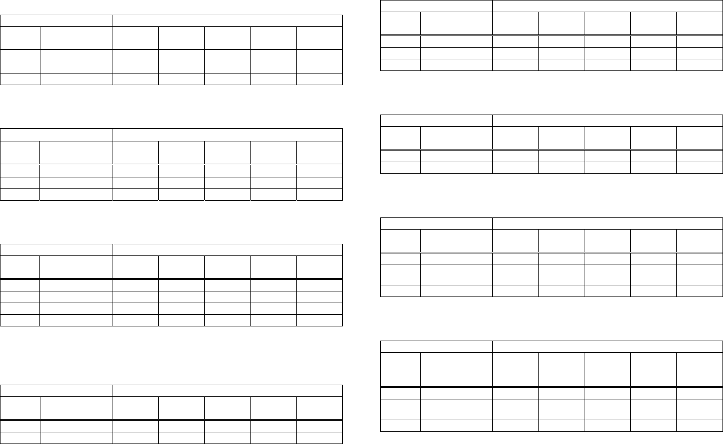
- 186 -
CT-S2000
• a = 116: When kind of paper is specified
Setting Status Sending Data
Stored
Value Print Control 1st Byte 2nd Byte 3rd Byte 4th Byte 5th Byte
1 Single-color
paper 49(“1”) ― ― ― ―
2 2-color paper 50(“2”) ― ― ― ―
• a = 201: When ACK output position is specified
Setting Status Sending Data
Stored
Value
ACK Output
Position 1st Byte 2nd Byte 3rd Byte 4th Byte 5th Byte
1 ACK-in-Busy 49(“1”) ― ― ― ―
2 ACK-while-Busy 50(“2”) ― ― ― ―
3 ACK-after-Busy 51(“3”) ― ― ― ―
• a = 202: Input buffer full Busy output/cancel timing
Setting Status Sending Data
Stored
Value
BUSY
Output/Cancel 1st Byte 2nd Byte 3rd Byte 4th Byte 5th Byte
1 49(“1”) ― ― ― ―
2 50(“2”) ― ― ― ―
3 51(“3”) ― ― ― ―
4 52(“4”)
• a=212: Wen DMA (Direct Memory Access) control of serial communication is
specified
Setting Status Sending Data
Stored
Value DMA control 1st Byte 2nd Byte 3rd Byte 4th Byte 5th Byte
1 Valid 49(“1”) ― ― ― ―
2 Invalid 50(“2”) ― ― ― ―
• a=213: When the flow control of virtual COM is specified.
Setting Status Sending Data
Stored
Value Flow control 1st Byte 2nd Byte 3rd Byte 4th Byte 5th Byte
1 PC setting 49(“1”) ― ― ― ―
2 DTR/DSR 50(“2”) ― ― ― ―
3 XON/XOF 51(“3”) ― ― ― ―
• a=214: When Kanji is specified
Setting Status Sending Data
Stored
Value Kanji 1st Byte 2nd Byte 3rd Byte 4th Byte 5th Byte
1 ON 49(“1”) ― ― ― ―
2 OFF 50(“2”) ― ― ― ―
• a=220: When maximum black mark width is specified
Setting Status Sending Data
Stored
Value
Maximum
B.M Width 1st Byte 2nd Byte 3rd Byte 4th Byte 5th Byte
0 0dot 49(“1”) 48(“0”) 48(“0”) 48(“0”) 48(“0”)
・
・
・
・
・
・
・
・
・
・
・
・
・
・
・
・
・
・
・
・
・
32767 32767dot 51(“3”) 50(“2”) 55(“7”) 54(“6”) 55(“7”)
• a=221: When maximum black mark page length is specified
Setting Status Sending Data
Stored
Value
Maximum
B.M page
length
1st Byte 2nd Byte 3rd Byte 4th Byte 5th Byte
0 0dot 49(“1”) 48(“0”) 48(“0”) 48(“0”) 48(“0”)
・
・
・
・
・
・
・
・
・
・
・
・
・
・
・
・
・
・
・
・
・
32767 32767dot 51(“3”) 50(“2”) 55(“7”) 54(“6”) 55(“7”)
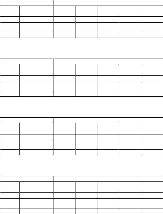
CT-S2000
• a=222: When head margin is specified
Setting Status Sending Data
Stored
Value Head Margin 1st Byte 2nd Byte 3rd Byte 4th Byte 5th Byte
0 0dot 49(“1”) 48(“0”) 48(“0”) 48(“0”) 48(“0”)
・ ・ ・ ・ ・ ・ ・
・ ・ ・ ・ ・ ・ ・
・ ・ ・ ・ ・ ・ ・
32767 32767dot 51(“3”) 50(“2”) 55(“7”) 54(“6”) 55(“7”)
• a=223: When bottom margin is specified
Setting Status Sending Data
Bottom
Margin
Stored
Value 1st Byte 2nd Byte 3rd Byte 4th Byte 5th Byte
0 0 48(“0”) 48(“0”) 48(“0”) ― ―
・ ・ ・ ・ ・ ・ ・
・ ・ ・ ・ ・ ・ ・
・ ・ ・ ・ ・ ・ ・
255 255 50(“2”) 53(“5”) 53(“5”) ― ―
• a=224: When cut distance is specified
Setting Status Sending Data
Stored
Value Cut Distance 1st Byte 2nd Byte 3rd Byte 4th Byte 5th Byte
0 0 48(“0”) 48(“0”) 48(“0”) ― ―
・ ・ ・ ・ ・ ・ ・
・ ・ ・ ・ ・ ・ ・
・ ・ ・ ・ ・ ・ ・
255 255 50(“2”) 53(“5”) 53(“5”) ― ―
• a=225: When head distance is specified
Setting Status Sending Data
Head
Distance
Stored
Value 1st Byte 2nd Byte 3rd Byte 4th Byte 5th Byte
0 0 48(“0”) 48(“0”) 48(“0”) ― ―
・ ・ ・ ・ ・ ・ ・
・ ・ ・ ・ ・ ・ ・
・ ・ ・ ・ ・ ・ ・
255 255 50(“2”) 53(“5”) 53(“5”) ― ―
- 187 -
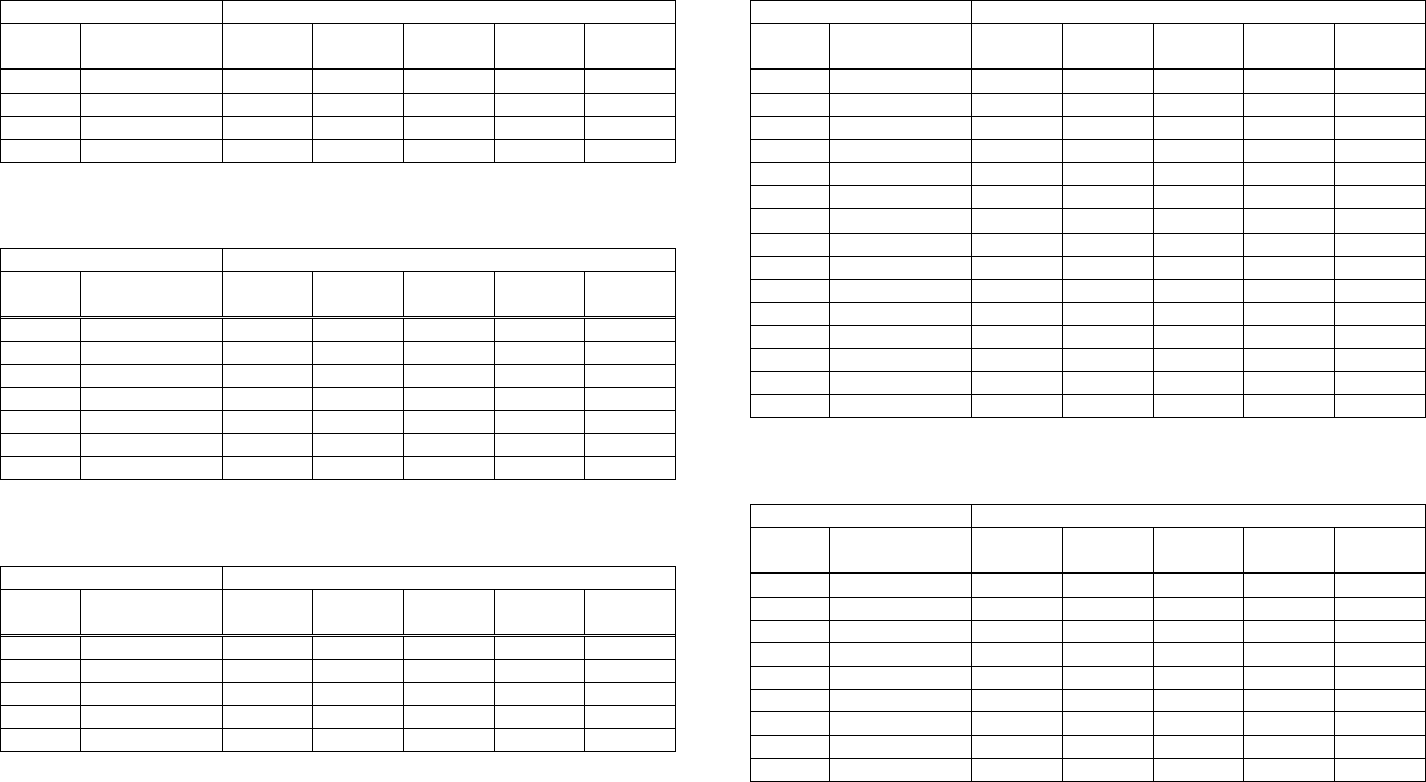
- 188 -
CT-S4000
• a = 1: When user NV memory capacity is specified
Setting Status Sending Data
Stored
Value
Memory
Capacity 1st Byte 2nd Byte 3rd Byte 4th Byte 5th Byte
1 1K bytes 49(“1”) ― ― ― ―
2 64K bytes 50(“2”) ― ― ― ―
3 128K bytes 51(“3”) ― ― ― ―
4 192K bytes 52(“4”) ― ― ― ―
• a = 2: When NV graphics memory capacity is specified
Setting Status Sending Data
Stored
Value
Memory
Capacity 1st Byte 2nd Byte 3rd Byte 4th Byte 5th Byte
1 None 49(“1”) ― ― ― ―
2 64K bytes 50(“2”) ― ― ― ―
3 128K bytes 51(“3”) ― ― ― ―
4 192K bytes 52(“4”) ― ― ― ―
5 256K bytes 53(“5”)
6 320K bytes 54(“6”)
7 384K bytes 55(“7”)
• a = 3: When paper width is specified
Setting Status Sending Data
Stored
Value Paper Width 1st Byte 2nd Byte 3rd Byte 4th Byte 5th Byte
5 512 dots 49(“1”) ― ― ― ―
6 576 dots 50(“2”) ― ― ― ―
7 660 dots 51(“3”) ― ― ― ―
8 720 dots 52(“4”) ― ― ― ―
9 832 dots 53(“5”) ― ― ― ―
• a = 5: When print density is specified
Setting Status Sending Data
Stored
Value Print Density 1st Byte 2nd Byte 3rd Byte 4th Byte 5th Byte
65530 70% 54(“6”) 53(“5”) 53(“5”) 51(“3”) 48(“0”)
65531 75% 54(“6”) 53(“5”) 53(“5”) 51(“3”) 49(“1”)
65532 80% 54(“6”) 53(“5”) 53(“5”) 51(“3”) 50(“2”)
65533 85% 54(“6”) 53(“5”) 53(“5”) 51(“3”) 51(“3”)
65534 90% 54(“6”) 53(“5”) 53(“5”) 51(“3”) 52(“4”)
65535 95% 54(“6”) 53(“5”) 53(“5”) 51(“3”) 53(“5”)
0 Basic density 48(“0”) ― ― ― ―
1 105% 49(“1”) ― ― ― ―
2 110% 50(“2”) ― ― ― ―
3 115% 51(“3”) ― ― ― ―
4 120% 52(“4”) ― ― ― ―
5 125% 53(“5”) ― ― ― ―
6 130% 54(“6”) ― ― ― ―
7 135% 55(“7”) ― ― ― ―
8 140% 56(“8”) ― ― ― ―
• a = 6: When printing speed is specified
Setting Status Sending Data
Stored
Value Print Speed 1st Byte 2nd Byte 3rd Byte 4th Byte 5th Byte
1 Speed level 1 49(“1”) ― ― ― ―
2 Speed level 2 50(“2”) ― ― ― ―
3 Speed level 3 51(“3”) ― ― ― ―
4 Speed level 4 52(“4”) ― ― ― ―
5 Speed level 5 53(“5”) ― ― ― ―
6 Speed level 6 54(“6”) ― ― ― ―
7 Speed level 7 55(“7”) ― ― ― ―
8 Speed level 8 56(“8”) ― ― ― ―
9 Speed level 9 57(“9”)
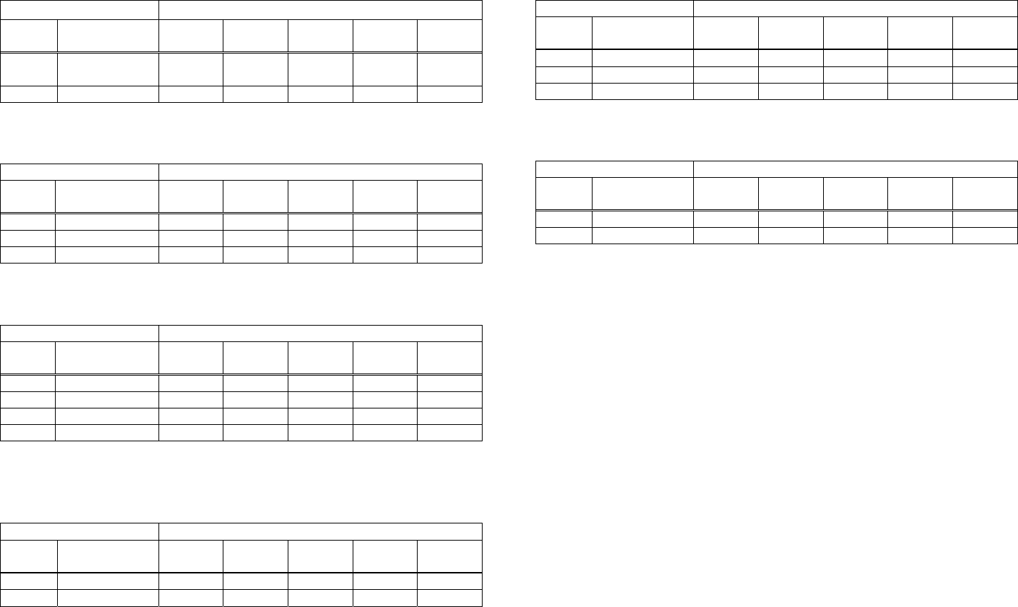
CT-S4000
• a=213: When the flow control of virtual COM is specified.
• a = 116: When kind of paper is specified
Setting Status Sending Data Setting Status Sending Data
Stored
Value
Stored
Value Print Control 1st Byte 2nd Byte 3rd Byte 4th Byte 5th Byte Flow control 1st Byte 2nd Byte 3rd Byte 4th Byte 5th Byte
1 PC setting 49(“1”) ― ― ― ―
Single-color
paper
1 49(“1”) ― ― ― ― 2 DTR/DSR 50(“2”) ― ― ― ―
3 XON/XOF 51(“3”) ― ― ― ―
2 2-color paper 50(“2”) ― ― ― ―
• a=214: When Kanji is specified
• a = 201: When ACK output position is specified
Setting Status Sending Data
Setting Status Sending Data
Stored
Value
Stored
Value
ACK Output
Position 1st Byte 2nd Byte 3rd Byte 4th Byte 5th Byte Kanji 1st Byte 2nd Byte 3rd Byte 4th Byte 5th Byte
1 ON 49(“1”) ― ― ― ―
1 ACK-in-Busy 49(“1”) ― ― ― ―
2 OFF 50(“2”) ― ― ― ―
2 ACK-while-Busy 50(“2”) ― ― ― ―
3 ACK-after-Busy 51(“3”) ― ― ― ―
• a = 202: Input buffer full Busy output/cancel timing
Setting Status Sending Data
Stored
Value
BUSY
Output/Cancel 1st Byte 2nd Byte 3rd Byte 4th Byte 5th Byte
1 49(“1”) ― ― ― ―
2 50(“2”) ― ― ― ―
3 51(“3”) ― ― ― ―
4 52(“4”)
• a=212: Wen DMA (Direct Memory Access) control of serial communication is
specified
Setting Status Sending Data
Stored
Value DMA control 1st Byte 2nd Byte 3rd Byte 4th Byte 5th Byte
1 Valid 49(“1”) ― ― ― ―
2 Invalid 50(“2”) ― ― ― ―
- 189 -
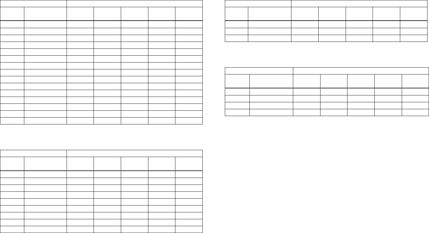
- 190 -
BD2-2220
• a = 5: When print density is specified
Setting Status Sending Data
Stored
Value Print Density 1st Byte 2nd Byte 3rd Byte 4th Byte 5th Byte
65530 70% 54(“6”) 53(“5”) 53(“5”) 51(“3”) 48(“0”)
65531 75% 54(“6”) 53(“5”) 53(“5”) 51(“3”) 49(“1”)
65532 80% 54(“6”) 53(“5”) 53(“5”) 51(“3”) 50(“2”)
65533 85% 54(“6”) 53(“5”) 53(“5”) 51(“3”) 51(“3”)
65534 90% 54(“6”) 53(“5”) 53(“5”) 51(“3”) 52(“4”)
65535 95% 54(“6”) 53(“5”) 53(“5”) 51(“3”) 53(“5”)
0 Basic density 48(“0”) ― ― ― ―
1 105% 49(“1”) ― ― ― ―
2 110% 50(“2”) ― ― ― ―
3 115% 51(“3”) ― ― ― ―
4 120% 52(“4”) ― ― ― ―
5 125% 53(“5”) ― ― ― ―
6 130% 54(“6”) ― ― ― ―
7 135% 55(“7”) ― ― ― ―
8 140% 56(“8”) ― ― ― ―
• a = 6: When printing speed is specified
Setting Status Sending Data
Stored
Value Print Speed 1st Byte 2nd Byte 3rd Byte 4th Byte 5th Byte
1 Speed level 1 49(“1”) ― ― ― ―
2 Speed level 2 50(“2”) ― ― ― ―
3 Speed level 3 51(“3”) ― ― ― ―
4 Speed level 4 52(“4”) ― ― ― ―
5 Speed level 5 53(“5”) ― ― ― ―
6 Speed level 6 54(“6”) ― ― ― ―
7 Speed level 7 55(“7”) ― ― ― ―
8 Speed level 8 56(“8”) ― ― ― ―
9 Speed level 9 57(“9”)
• a = 201: When ACK output position is specified
Setting Status Sending Data
Stored
Value
ACK Output
Position 1st Byte 2nd Byte 3rd Byte 4th Byte 5th Byte
1 ACK-in-Busy 49(“1”) ― ― ― ―
2 ACK-while-Busy 50(“2”) ― ― ― ―
3 ACK-after-Busy 51(“3”) ― ― ― ―
• a = 202: Input buffer full Busy output/cancel timing
Setting Status Sending Data
Stored
Value
BUSY
Output/Cancel 1st Byte 2nd Byte 3rd Byte 4th Byte 5th Byte
1 49(“1”) ― ― ― ―
2 50(“2”) ― ― ― ―
3 51(“3”) ― ― ― ―
4 52(“4”)

- 191 -
PMU2XXX
• a = 5: When print density is specified
Setting Status Sending Data
Stored
Value Print Density 1st Byte 2nd Byte 3rd Byte 4th Byte 5th Byte
65530 70% 54(“6”) 53(“5”) 53(“5”) 51(“3”) 48(“0”)
65531 75% 54(“6”) 53(“5”) 53(“5”) 51(“3”) 49(“1”)
65532 80% 54(“6”) 53(“5”) 53(“5”) 51(“3”) 50(“2”)
65533 85% 54(“6”) 53(“5”) 53(“5”) 51(“3”) 51(“3”)
65534 90% 54(“6”) 53(“5”) 53(“5”) 51(“3”) 52(“4”)
65535 95% 54(“6”) 53(“5”) 53(“5”) 51(“3”) 53(“5”)
0 Basic density 48(“0”) ― ― ― ―
1 105% 49(“1”) ― ― ― ―
2 110% 50(“2”) ― ― ― ―
3 115% 51(“3”) ― ― ― ―
4 120% 52(“4”) ― ― ― ―
5 125% 53(“5”) ― ― ― ―
6 130% 54(“6”) ― ― ― ―
7 135% 55(“7”) ― ― ― ―
8 140% 56(“8”) ― ― ― ―
• a = 6: When printing speed is specified
Setting Status Sending Data
Stored
Value Print Speed 1st Byte 2nd Byte 3rd Byte 4th Byte 5th Byte
1 Speed level 1 49(“1”) ― ― ― ―
2 Speed level 2 50(“2”) ― ― ― ―
3 Speed level 3 51(“3”) ― ― ― ―
4 Speed level 4 52(“4”) ― ― ― ―
5 Speed level 5 53(“5”) ― ― ― ―
6 Speed level 6 54(“6”) ― ― ― ―
7 Speed level 7 55(“7”) ― ― ― ―
8 Speed level 8 56(“8”) ― ― ― ―
9 Speed level 9 57(“9”)
• a = 201: When ACK output position is specified
Setting Status Sending Data
Stored
Value
ACK Output
Position 1st Byte 2nd Byte 3rd Byte 4th Byte 5th Byte
1 ACK-in-Busy 49(“1”) ― ― ― ―
2 ACK-while-Busy 50(“2”) ― ― ― ―
3 ACK-after-Busy 51(“3”) ― ― ― ―
• a = 202: Input buffer full Busy output/cancel timing
Setting Status Sending Data
Stored
Value
BUSY
Output/Cancel 1st Byte 2nd Byte 3rd Byte 4th Byte 5th Byte
1 49(“1”) ― ― ― ―
2 50(“2”) ― ― ― ―
3 51(“3”) ― ― ― ―
4 52(“4”)
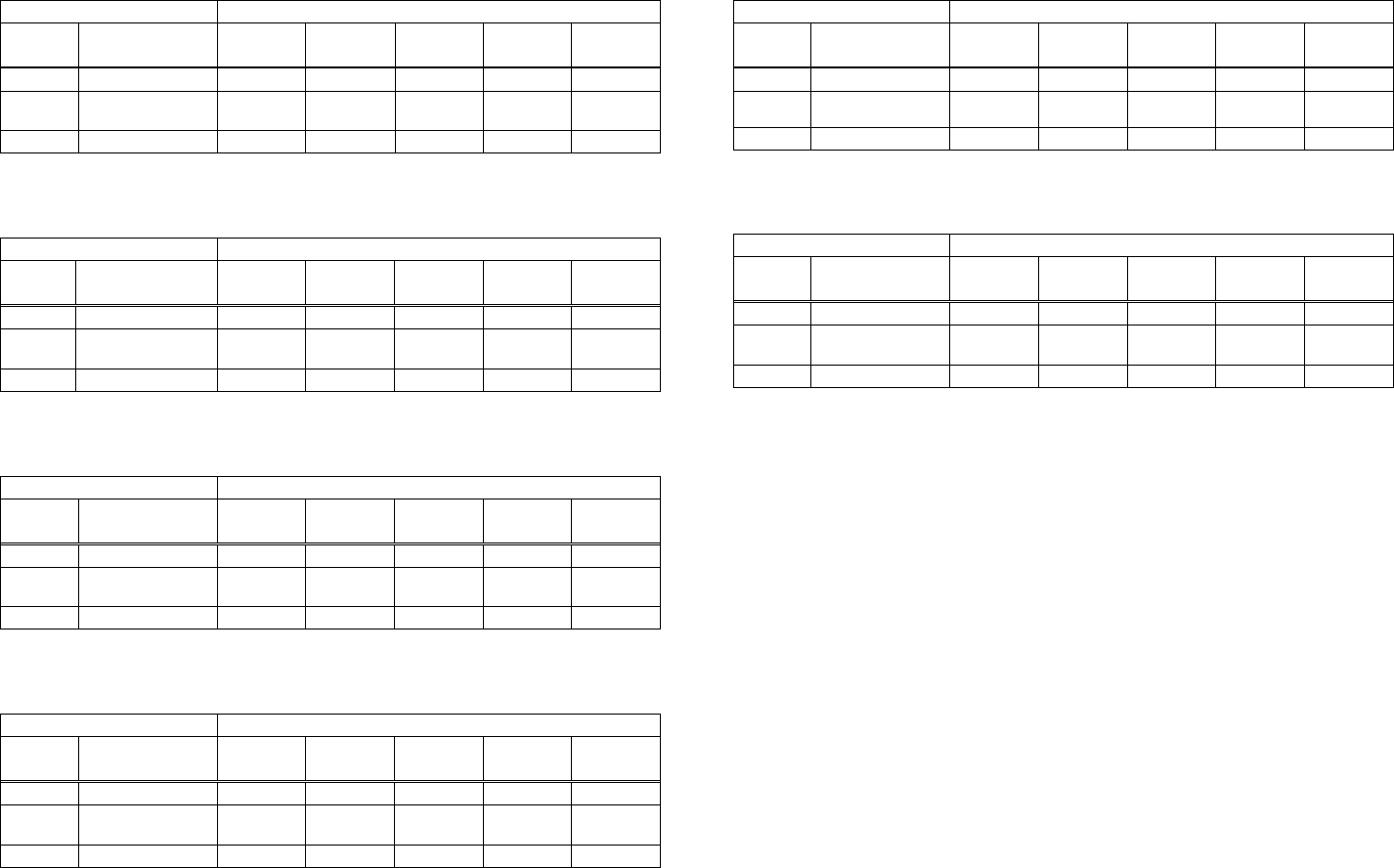
- 192 -
PMU2XXX
• a=220: When maximum black mark width is specified
Setting Status Sending Data
Stored
Value
Maximum B.M
Width 1st Byte 2nd Byte 3rd Byte 4th Byte 5th Byte
0 0dot 49(“1”) 48(“0”) 48(“0”) 48(“0”) 48(“0”)
・
・
・
・
・
・
・
・
・
・
・
・
・
・
・
・
・
・
・
・
・
32767 32767dot 51(“3”) 50(“2”) 55(“7”) 54(“6”) 55(“7”)
• a=221: When maximum length of black mark page is specified
Setting Status Sending Data
Stored
Value
Maximum B.M
Page Length 1st Byte 2nd Byte 3rd Byte 4th Byte 5th Byte
0 0dot 49(“1”) 48(“0”) 48(“0”) 48(“0”) 48(“0”)
・
・
・
・
・
・
・
・
・
・
・
・
・
・
・
・
・
・
・
・
・
32767 32767dot 51(“3”) 50(“2”) 55(“7”) 54(“6”) 55(“7”)
• a=222: When head margin is specified
Setting Status Sending Data
Stored
Value Head Margin 1st Byte 2nd Byte 3rd Byte 4th Byte 5th Byte
0 0dot 49(“1”) 48(“0”) 48(“0”) 48(“0”) 48(“0”)
・
・
・
・
・
・
・
・
・
・
・
・
・
・
・
・
・
・
・
・
・
32767 32767dot 51(“3”) 50(“2”) 55(“7”) 54(“6”) 55(“7”)
• a=223: When bottom margin is specified
Setting Status Sending Data
Stored
Value
Bottom
Margin 1st Byte 2nd Byte 3rd Byte 4th Byte 5th Byte
0 0 48(“0”) 48(“0”) 48(“0”) ― ―
・
・
・
・
・
・
・
・
・
・
・
・
・
・
・
・
・
・
・
・
・
255 255 50(“2”) 53(“5”) 53(“5”) ― ―
• a=224: When cut distance is specified
Setting Status Sending Data
Stored
Value Cut Distance 1st Byte 2nd Byte 3rd Byte 4th Byte 5th Byte
0 0 48(“0”) 48(“0”) 48(“0”) ― ―
・
・
・
・
・
・
・
・
・
・
・
・
・
・
・
・
・
・
・
・
・
255 255 50(“2”) 53(“5”) 53(“5”) ― ―
• a=225: When head distance is specified
Setting Status Sending Data
Stored
Value
Head
Distance 1st Byte 2nd Byte 3rd Byte 4th Byte 5th Byte
0 0 48(“0”) 48(“0”) 48(“0”) ― ―
・
・
・
・
・
・
・
・
・
・
・
・
・
・
・
・
・
・
・
・
・
255 255 50(“2”) 53(“5”) 53(“5”) ― ―
- 193 -
fn=7: Function 7 Copying User-defined Page
GS ( E pL pH fn a d1 d2
[Code] <1D>H<28>H<45>H<pL><pH><fn><a><d1><d2>
[Range] (pL+pH×256)=4:(pL=4、pH=0)
fn=7
a =10、12、17
[Outline] [The specification which is common to the model]
• Copies the data of user-defined code page in the font specified by “a”.
• Configuration of customized value No.
d1 d2 Function
31 30 Loads the character code page data specified by “a” in storage area to work
area.
30 31 Saves the character code page data in work area to the storage area of the
font specified by “a”.
• Work area: Area where data is initialized by power OFF or resetting (initialize).
Operation is made in accordance with the data set in this area.
• Storage area: Area where data is not initialized by power OFF or resetting (initialize).
• User-defined code page: Page 255 (ESC t 255)
• This function operates only in printer function setting mode.
[The specification which depend on the model]
CT-S300/CT-S310
a Font Type
10 Font B: 9 (horizontal) x17 (vertical)
12 Font A: 12 (horizontal) x24 (vertical)
17 Font C: 8 (horizontal) x16 (vertical)
CT-S280/CT-S2000/CT-S4000/BD2-2220/PMU2XXX
a Font Type
10 Font B: 9 (horizontal) x24 (vertical)
12 Font A: 12 (horizontal) x24 (vertical)
17 Font C: 8 (horizontal) x16 (vertical)
- 194 -
Work Area
fn=8: Function 8 Defining Data by the Column Format to Character Code Page of
GS ( E pL pH fn y c1 c2 [xd1...d(y×x)]k
[Code] <1D>H<28>H<45>H<pL><pH><fn><y><c1><c2>[<x><d1>..<d(yXx)>]<k>
[Range] 5≦(pL+pH×256)≦65535
fn=8
y=2 (At selection of font C)
y=3 (At selection of other than font C)
128≦c1≦c2≦255
0≦x≦12 (At selection of font A)
0≦x≦9 (At selection of font B)
0≦x≦8 (At selection of font C)
0≦d≦255
k=c2-c1+1
[Outline] [The specification which is common to the model]
Defines the data in column format in units of character on the code page in RAM.
Operates only in printer function setting mode.
Data structure(9×17)
d1 d4 ……………………d25
d3 d6 ……………………d27
bit 7 ○ ○ ○ ○ ○ ○ ○ ○ ○
6 ○ ○ ○ ○ ○ ○ ○ ○ ○
5 ● ○ ○ ○ ● ● ○ ● ●
4 ● ○ ● ○ ○ ○ ○ ○ ○
3 ● ○ ○ ○ ○ ● ○ ○ ○
2 ● ● ○ ● ○ ● ○ ○ ●
1 ○ ○ ● ○ ● ● ● ○ ○
0 ○ ○ ○ ○ ○ ○ ○ ○ ○
7 ○ ○ ○ ○ ○ ○ ○ ○ ○
6 ○ ● ○ ○ ○ ● ○ ● ○
5 ● ○ ● ○ ● ○ ○ ○ ○
4 ● ○ ○ ● ○ ○ ● ○ ●
3 ● ● ○ ○ ○ ● ○ ● ●
2 ○ ○ ● ○ ○ ○ ○ ○ ○
1
○ ○ ○ ○ ○ ○ ○ ○ ○
0
7 ○ ○ ○ ○ ○ ○ ○ ○ ○
6
5
4
3
2
1
0
○ ○ ○ ● ● ○ ○ ○ ○ Bits 6 through 0 are not character data
● ○ ● ○ ○ ● ● ● ○
● ● ○ ● ○ ○ ● ○ ●
○ ● ○ ○ ● ○ ○ ○ ○
● ● ● ○ ○ ○ ○ ● ○
○ ○ ○ ● ○ ● ○ ○ ●
○ ○ ○ ○ ○ ○ ○ ○ ○
- 195 -
Work Area
fn=9: Function 9 Defining Data in the Raster Format to the Character Code Page of
GS ( E pL pH fn x c1 c2 [y d1...d(x×y)]k
[Code] <1D>H<28>H<45>H<pL><pH><fn><x><c1><c2>[<y><d1>..<d(yXx)>]<k>
[Range] 5≦(pL+pH×256)≦65535
fn=9
y=1(At selection of font C) 、y=2 (At selection of other than font C)
128≦c1≦c2≦255
0≦x≦24 (At selection of font A)
0≦x≦16 (At selection of font C)、0≦d≦255
k=c2-c1+1
CT-S300/CT-S310
0≦x≦17 (At selection of font B)
CT-S280/CT-S2000/CT-S4000/BD2-2220/PMU2XXX
0≦x≦24 (At selection of font B)
[Outline] [The specification which is common to the model]
Defines the data in raster format in units of character on the character code page in work area.
Operates only in printer function setting mode.
Data structure(12×24)
d1 (odd number) d2 (even number)
d1
3
7
9
11
13
15
17
19
21
23
25
27
29
31
33
35
37
39
41
43
45
47
7 6 5 4 321076543210
○ ○ ○ ○ ○○○○○○○○○○○○
○ ○ ○ ○ ○○○○○○○○○○○○
● ○ ○ ○ ●●○●●○○○○○○○
● ○ ● ○ ○○○○●○●○●○●○
● ○ ○ ○ ○●○○●○○○○○○○
● ● ○ ● ○●○○●●○●○●○●
○ ○ ● ○ ●●●○○○●○●○●○
○ ○ ○ ○ ○○○○○○○○○○○○
○ ○ ○ ○ ○○○○○○○○○○○○
○ ● ○ ○ ○●○●○●○○○○○○
● ○ ● ○ ●○○○●○●○●○●○
● ○ ○ ● ○○●○●○○●○●○●
● ● ○ ○ ○●○●●●○○○○○○
○ ○ ● ○ ○○○○○○●○●○●○
○ ○ ○ ○ ○○○○○○○○○○○○
○ ○ ○ ○ ○○○○○○○○○○○○
○ ○ ○ ● ●○○○○○○●○●○●
● ○ ● ○ ○●●●●○●○●○●○
● ● ○ ● ○○●○●●○●○●○●
○ ● ○ ○ ●○○○○●○○○○○○
● ● ● ○ ○○○●●●●○●○●○
○ ○ ○ ● ○●○○○○○●○●○●
○ ○ ○ ○ ○○○○○○○○○○○○
Bits 3 through 0 are not character data

- 196 -
fn=10: Function 10 Erasing Data of Character Code Page Data in Work Area
GS ( E pL pH fn c1 c2
[Code] <1D>H<28>H<45>H<pL><pH><fn><c1><c2>
[Range] (pL+pH×256)=3
fn=10
128≦c1≦c2≦255
[Outline] [The specification which is common to the model]
Erases (set to space) data in units of character on the character code page in work area.
Operates only in printer function setting mode.
- 197 -
fn=11: Function 11 Setting Communication Conditions
GS ( E pL pH fn a d1...dk
[Code] <1D>H<28>H<45>H<pL><pH><fn><a><d1>...<dk>
[Range] 3≦(pL+pH×256)≦65535(0≦pL≦255、0≦pH≦255)
fn=11
1≦a≦4 (Not changed in other than specified range)
48≦d≦57 (Not changed in other than specified range)
1≦k≦6
[Outline] [The specification which is common to the model]
Sets the communication conditions of serial interface specified by “a”.
• a = 1: Setting baud rate
d3 d4
Baud Rate d1 D2 d5 d6
●1200 49(“1”) 50(“2”) 48(“0”) 48(“0”) ---- ----
2400 50(“2”) 52(“4”) 48(“0”) 48(“0”) ---- ----
4800 52(“4”) 56(“8”) 48(“0”) 48(“0”) ---- ----
▲9600 57(“9”) 54(“6”) 48(“0”) 48(“0”) ---- ----
△19200 49(“1”) 57(“9”) 50(“2”) 48(“0”) 48(“0”) ----
38400 51(“3”) 56(“8”) 52(“4”) 48(“0”) 48(“0”) ----
●57600 53(“5”) 55(“7”) 54(“6”) 48(“0”) 48(“0”) ----
●115200 49(“1”) 49(“1”) 53(“5”) 50(“2”) 48(“0”) 48(“0”)
●・・・support by CT-S2000、CT-S4000、PMU2XXX
*PMU2XXX: Prohibit the use of 57600bps.
△・・・Default : CT-S300、CT-S2000(JPN/EUR)、CT-S4000(JPN/EUR) 、CT-S310
▲・・・Default : CT-S280、CT-S2000(USA)、CT-S4000(USA)、BD2-2220、PMU2XXX
• a = 2: Setting to specified parity
Parity Setting
d1
48 (Default) No parity
49 Odd parity
50 Even parity
• a = 3: Setting to specified flow control
Flow Control
d1
48 (Default) DSR/DTR
49 XON/XOFF
• a = 4: Setting to specified data length
Setting Data Length
d1
55 7-bit length
56 (Default) 8-bit length
• Operates only in printer function setting mode.
• Which of dip SW or memory SW is used at initialization depends on “Selecting communication
condition setting” of dip SW1-1.
- 198 -
fn=12: Function 12 Sending the Set Communication Conditions
GS ( E pL pH fn a
[Code] <1D>H<28>H<45>H<pL><pH><fn><a>
[Range] (pL+pH×256)=2 (pL=2、pH=0)
fn=12
1≦a≦4 (Does not send in other than specified range)
[Outline] [The specification which is common to the model]
Sends communication conditions of serial interface specified by “a”.
Hex. No. of Data
37H 1
Header
33H 1
ID
31H(“1”)~34H(“4”) 1
Kind of communication conditions (a)
1FH 1
Separation number
30H~39H 1~6
Set value
00H 1
NULL
Set value
• a = 1: At specification of baud rate
Baud Rate d1 d2 d3 d4 d5 d6
●1200 49(“1”) 50(“2”) 48(“0”) 48(“0”) ---- ----
2400 50(“2”) 52(“4”) 48(“0”) 48(“0”) ---- ----
4800 52(“4”) 56(“8”) 48(“0”) 48(“0”) ---- ----
9600 57(“9”) 54(“6”) 48(“0”) 48(“0”) ---- ----
19200 (Default) 49(“1”) 57(“9”) 50(“2”) 48(“0”) 48(“0”) ----
38400 51(“3”) 56(“8”) 52(“4”) 48(“0”) 48(“0”) ----
●57600 53(“5”) 55(“7”) 54(“6”) 48(“0”) 48(“0”) ----
●115200 49(“1”) 49(“1”) 53(“5”) 50(“2”) 48(“0”) 48(“0”)
●・・・support by CT-S2000、CT-S4000
• a = 2: At specification of parity
d1 Parity Setting
48 No parity
49 Odd parity
50 Even parity
• a = 3: At specification of flow control
d1 Flow Control
48 DTR/DSR
49 XON/XOFF
• a = 4: At specification of data length
d1 Setting Data Length
48 7-bit length
49 8-bit length
- 199 -
State at Shipment
fn=255: Function 255 Setting All Contents Set by Printer Function Setting Mode to the
GS ( E pL pH fn a
[Code] <1D>H<28>H<45>H<pL><pH><fn><a>
[Range] (pL+pH×256)=2
fn=255
a=3, 5, 7, 11, 255
[Outline] [The specification which is common to the model]
Restores various kinds of function set by printer function setting mode to the setting at the time of
shipment (initial value described in User’s Manual).
a Function
3 Memory switch
5 Customized value
7 Character code
11 Communication conditions of serial interface
Sets all contents set in printer function setting mode to the state at the time
of shipment.
255
- 200 -
GS ( K pL pH fn m
CT-S280 CT-S300 CT-S2000 CT-S4000 BD2-2220 CT-S310
support model PMU2XXX
[Function] Selecting print control method
[Outline] [The specification which is common to the model]
Executes the setting related to the print control specified by the value of “fn”.
Function No. (fn) Function
Function 49 Sets printing density.
Function 50 Sets printing speed.
Function 97 Sets the number of divisions for head conducting.*
*fn=97 is supported by only CT-S300, CT-S310
- 201 -
fn=49: Function 49 Setting Printing Density
GS ( K pL pH fn m
[Code] <1D>H<28>H<4B>H<pL><pH><fn><m>
[Range] (pL+pH×256)=2:(pL=2、pH=0)
fn=49
0≦m≦8、250≦m≦255
[Default] m = 0 (Customized value setting value)
[Outline] [The specification which is common to the model]
Sets printing density.
m Printing Density
250 Selects density level –6 (70%)
251 Selects density level –5 (75%)
252 Selects density level –4 (80%)
253 Selects density level –3 (85%)
254 Selects density level –2 (90%)
255 Selects density level –1 (95%)
0 Selects standard density (100%)
1 Selects density level + 1 (105%)
2 Selects density level + 2 (110%)
3 Selects density level + 3 (115%)
4 Selects density level + 4 (120%)
5 Selects density level + 5 (125%)
6 Selects density level + 6 (130%)
7 Selects density level + 7 (135%)
8 Selects density level + 8 (140%)
- 202 -
fn=50: Function 50 Setting Printing Speed
GS ( K pL pH fn m
[Code] <1D>H<28>H<4B>H<pL><pH><fn><m>
[Range] (pL+pH×256)=2(pL=2、pH=0)
fn=50
0≦m≦9、48≦m≦57
[Default] m = 0 (Customized value setting)
[Outline] [The specification which is common to the model]
Sets printing speed.
m Printing Speed
0,48 Selects customized value setting
1,49 Selects printing speed level 1.
2,50 Selects printing speed level 2.
3,51 Selects printing speed level 3.
4,52 Selects printing speed level 4.
5,53 Selects printing speed level 5.
6,54 Selects printing speed level 6.
7,55 Selects printing speed level 7.
8,56 Selects printing speed level 8.
9,57 Selects printing speed level 9.
- 203 -
fn=97: Function 97 Setting Number of Divisions for Head Conducting
GS ( K pL pH fn m
[Code] <1D>H<28>H<4B>H<pL><pH><fn><m>
[Range] (pL+pH×256)=2(pL=2、pH=0)
fn=97
m=0、2、4、48、50、52
[Default] m=0 m = 0 (Customized value setting)
[Outline] [The specification which depend on the model]
CT-S300/CT-S310
Sets the number of divisions for head conducting.
m No. of Divisions for Head Conducting
0,48 Selects customized value setting
2,50 Selects 2-division conducting.
4,52 Selects 4-division conducting.
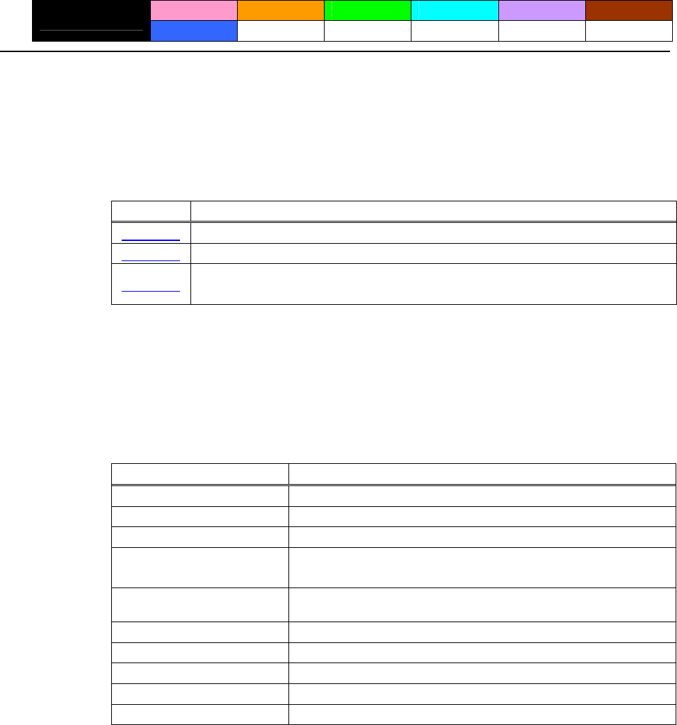
- 204 -
GS ( M pL pH fn m
CT-S280 CT-S300 CT-S2000 CT-S4000 BD2-2220 CT-S310
support model PMU2XXX
[Function] Customizing the printer
[Outline] [The specification which depend on the model]
Executes processing related to escape/recovery of the value set in the work area or the data defined
by various kinds of command.
fn Function
Function 1 Copies the set value stored in work area to the storage area.
Function 2 Copies the set value stored in storage area to the work area.
Specifies the auto loading function of the set value at initialization to be valid or
invalid.
Function 3
• Work area:
Area where data is initialized by power OFF of resetting (initialize). Operation is made in
accordance with the data set in this area.
• Storage area:
Area where data is not initialized by power OFF or resetting (initialize).
Commands for this function
Command Type Command
ESC c3、GS a
Status relations
Macro registration GS :
ESC M、ESC R、ESC t
Character type
ESC !、ESC –、ESC E、ESC G、ESC V、ESC {、GS !、GS B
Font attribute GS b、GS ( N*
Line feed amount, character
space ESC SP、ESC 2、ESC 3
GS H、GS f、GS h、GS w
Barcode
2-dimensional code(★) GS ( k<fn65~70>
ESC D、ESC T、ESC a、GS L、GS W
Print position
FS !、FS &、FS ( A、FS –、FS . 、FS C、FS S、FS W
Kanji control relations
ESC c 4、ESC c 5、GS ( D、GS ( H <fn49>、 GS P
Other
★ … Supported with CT-S2000 and CT-S4000 label models.
* … Not supported with BD2-2220.
- 205 -
fn=1、49: Function 1 Copies the set value stored in work area to the storage area
GS ( M pL pH fn m
[Code] <1D>H<28>H<4D>H<pL><pH><fn><m>
[Range] (pL+pH×256)=2:(pL=2、pH=0)
fn=1、49
m=1、49
[Outline] [The specification which depend on the model]
Copies the set value stored in work area to the storage area.
[Caution] • This command allows writing to non-volatile memory. Therefore, using this command frequently
may result in breakage of non-volatile memory. Use this command appropriately [10 times
max./day].
• During execution of this command, the printer is in Busy state and stops receiving operation.
Therefore, data transmission from the host is prohibited.
fn=2、50: Function 2 Copies the set value stored in storage area to the work area
GS ( M pL pH fn m
[Code] <1D>H<28>H<4D>H<pL><pH><fn><m>
[Range] (pL+pH×256)=2:(pL=2、pH=0)
fn=2、50
m=0、1、48、49
[Outline] [The specification which depend on the model]
Changes the set value of work area by the value of “m”.
m Function
0、48 Sets all set values of work area to the initial value described in the specification.
Copies the set value stored in storage area to the work area.
1、49 When there is no set value in storage area, sets the value to the initial value described
in the specification.
- 206 -
initialization to be valid o
fn=3、51: Function 3 Specifies the auto loading function of the set value at
r invalid
GS ( M pL pH fn m
[Code] <1D>H<28>H<4D>H<pL><pH><fn><m>
[Range] (pL+pH×256)=2:(pL=2、pH=0)
fn=3、51
m=0、1、48、49
[Outline] [The specification which depend on the model]
Determines the setting of storage area at initialization to the work area by the value of “m”.
m Function
0、48 Does not copy data from storage area to work area at initialization.
1、49 Copies data from storage area to work area at initialization.
- 207 -
GS ( N pL pH fn m
CT-S280 CT-S300 CT-S2000 CT-S4000 BD2-2220 CT-S310
support model PMU2XXX
[Function] Designating font attribute
[Outline] [The specification which depend on the model]
Executes processing of font attribute by the specified fn value.
fn Function
Selects character color.
48
fn=48: Function 48 Selects character color
GS ( N pL pH fn m
[Code] <1D>H<28>H<4E>H<pL><pH><fn><m>
[Range] (pL+pH×256)=2:(pL=2、pH=0)
fn=48
m=49 (At single color paper setting)
m=49、50 (At 2-color paper setting)
[Default] m=49
[Outline] [The specification which depend on the model]
Prints the succeeding characters with the energy set in m.
m Function
49 High energy
50 Low energy
- 208 -
2.2.17 2-dimensional code Commands
GS ( k pL pH cn fn [parameter]
CT-S280 CT-S300 CT-S2000 CT-S4000 BD2-2220 CT-S310
support model PMU2XXX
[Function] Setting and printing 2-dimensional code
[Outline] [The specification which depend on the model]
• Executes processing specified by function code (fn) with the 2-dimensional code specified
by cn.
• 2-dimensional codes selectable with the value of cn are shown below.
cn 2-dimensional code
48 PDF417
49 QRCode
• Executes various processing related to 2-dimensional code specified by fn.
Function
No.
cn fn Code Function
65 GS ( k pL pH cn fn n Function65 Sets the number of digits of PDF417.
66 GS ( k pL pH cn fn n Function66 Sets the number of steps of PDF417.
67 GS ( k pL pH cn fn n Function67 Sets the module width of PDF417.
68 GS ( k pL pH cn fn n Function68 Sets the height of the step of PDF417.
69 GS ( k pL pH cn fn m n Function69 Sets error correction level of PDF417.
70 GS ( k pL pH cn fn m Function70 Sets the option of PDF417.
80 GS ( k pL pH cn fn m
d1 … dk Function80
Stores received data to symbol storage
area*.
48
Prints 2-dimensional code data* of
2-dimensional code data storage area.
81 GS ( k pL pH cn fn m Function81
Sends size information of
2-dimensional code data in
2-dimensional code data storage area.
82 GS ( k pL pH cn fn m Function82
Function
No.
cn fn Code Function
GS ( k pL pH cn fn n1
n2
65 Function165 Specifies QRCode model.
67 GS ( k pL pH cn fn n Function167 Sets the size of QRCode module.
69 GS ( k pL pH cn fn m n Function169 Sets error correction level of QRCode.
GS ( k pL pH cn fn m Stores received data to 2-dimensional
code data storage area.
80 Function180
d1 … dk
49
Prints 2-dimensional code data in
2-dimensional code data storage area.
81 GS ( k pL pH cn fn m Function181
Sends the size information of
2-dimensional code data in
2-dimensional code data storage area.
Function18282 GS ( k pL pH cn fn m
* 2-dimensional code data storage area ... Indicates the area where [cn=48: Function
80], and [cn=49: Function 180] data are
stored.
* 2-dimensional code data ... Indicates data (d1 ... dk) of [cn=48: Function 80],
[cn=49: Function 180].

- 209 -
fn=65: Function 65 Setting the number of digits of PDF417
GS ( k pL pH cn fn n
[Code] <1D>H<28>H<6B>H<pL><pH><cn><fn><n>
[Range] (pL+pH×256)=3(pL=3、pH=0)
cn=48
fn=65
0≦n≦30
[Outline] [The specification which depend on the model]
Sets the number of digits of PDF417.
• With n=0, automatic processing is specified.
* For the number of digits in this case, the number of code words is calculated based on
current print area.
• With n≠0, the number of digits of PDF417 data area is designated to n code word.
[Caution] • Start pattern and stop pattern are not included in the number of digits.
• Left-step indicator code word and right-step indicator code word are not included in the
number of digits.
[Default] n=0
fn=66: Function 66 Setting the number of steps of PDF417
GS ( k pL pH cn fn n
[Code] <1D>H<28>H<6B>H<pL><pH><cn><fn><n>
[Range] (pL+pH×256)=3(pL=3、pH=0)
cn=48
fn=66
n=0、3≦n≦90
[Outline] [The specification which depend on the model]
Sets the number of steps of PDF417.
• With n=0, automatic processing is specified.
* The number of steps in this case is calculated based on the number of code words and
current print area.
• With n≠0, the number of steps of PDF417 is set to n steps.
[Default] n=0

- 210 -
fn=67: Function 67 Setting module width of PDF417
GS ( k pL pH cn fn n
[Code] <1D>H<28>H<6B>H<pL><pH><cn><fn><n>
[Range] (pL+pH×256)=3(pL=3、pH=0)
cn=48
fn=67
2≦n≦8
[Outline] [The specification which depend on the model]
Sets the width of one module of PDF417 to n dots.
[Default] n=3
fn=68: Function 68 Setting the height of step of PDF417
GS ( k pL pH cn fn n
[Code] <1D>H<28>H<6B>H<pL><pH><cn><fn><n>
[Range] (pL+pH×256)=3(pL=3、pH=0)
cn=48
fn=68
2≦n≦8
[Outline] [The specification which depend on the model]
Sets the height of the step of PDF417 to [Module width (Function 67) x n].
[Default] n=3
- 211 -
fn=69: Function 69 Setting error correction level of PDF417
GS ( k pL pH cn fn m n
[Code] <1D>H<28>H<6B>H<pL><pH><cn><fn><m><n>
[Range] (pL+pH×256)=4(pL=4、pH=0)
cn=48
fn=69
m=48、49
48≦n≦56 (when m
= 48 is specified)
1≦n≦40 (when m = 49 is specified)
[Outline] [The specification which depend on the model]
Sets error correction level of PDF417
• When m=48, set by the level of n.
n Fnction Error Correction Code Words
48 Selects error correction level 0. 2
49 Selects error correction level 1. 4
50 Selects error correction level 2. 8
51 Selects error correction level 3. 16
52 Selects error correction level 4. 32
53 Selects error correction level 5. 64
54 Selects error correction level 6. 128
55 Selects error correction level 7. 256
56 Selects error correction level 8. 512
• When m=49, [set by the ratio (nx10%)] to the number of data code words.
Calculation result (A) = Value of (number of data code words xnx0.1) rounded to the
nearest one.
Result (A) Fnction Error Correction Code Words
0~3 Selects error correction level 1. 4
4~10 Selects error correction level 2. 8
11~20 Selects error correction level 3. 16
21~45 Selects error correction level 4. 32
46~100 Selects error correction level 5. 64
101~200 Selects error correction level 6. 128
201~400 Selects error correction level 7. 256
401~ Selects error correction level 8. 512
[Default] m=49、n=1
- 212 -
fn=70: Function 70 Setting Options for PDF417
GS ( k pL pH cn fn m
[Code] <1D>H<28>H<6B>H<pL><pH><cn><fn><m>
[Range] (pL+pH×256)=3(pL=3、pH=0)
cn=48
fn=70
m=0、1
[Outline] [The specification which depend on the model]
Specifies or clears the PDF417 option.
m Function
簡易 PDF417 の処理を解除
0
簡易 PDF417 の処理を指定
1
[Caution] • When cleared with m=0, standard processing for PDF417 is conducted thereafter.
[Default] m=0
fn=80: Function 80 Storing received data to 2-dimensional code data storage
area
GS ( k pL pH cn fn m d1...dk
[Code] <1D>H<28>H<6B>H<pL><pH><cn><fn><m><d1…dk>
[Range] 4≦(pL+pH×256)≦65535(0≦pL≦255 、0≦pH≦255)
cn=48
fn=80
m=48
0≦d≦255
k=(pL+pH×256)-3
[Outline] [The specification which depend on the model]
Stores PDF417 2-dimensional code data (d1…dk) to 2-dimensional code data storage area.
• Processes [(pL+pH×256)-3] of d1 and thereafter as 2-dimensional code data.
[Sample Program]
[Print Results]
Refer to Sample Program and Print Results for fn=81: Function181.
- 213 -
storage area
fn=81: Function 81 Printing 2-dimensional code data in 2-dimensional code data
GS ( k pL pH cn fn m
[Code] <1D>H<28>H<6B>H<pL><pH><cn><fn><m>
[Range] (pL+pH×256)=3(pL=3、pH=0)
cn=48
fn=81
m=48
[Outline] [The specification which depend on the model]
Prints PDF417 stored in 2-dimensional code data storage area.
[Caution] • Quiet zone (blank area around PDF417) shall be secured by the user.
[Sample Program]
LPRINT CHR$(&H1D) ;”(”;”k”; CHR$(10); CHR$(0); CHR$(48); CHR$(80); CHR$(48);
LPRINT “CITIZEN”
LPRINT CHR$(&H1D) ;”(”;”k”; CHR$(3); CHR$(0); CHR$(48); CHR$(81); CHR$(48);
[Print Results]
- 214 -
code data storage area
fn=82: Function 82 Sending the size of 2-dimensional code data in 2-dimensional
GS ( k pL pH cn fn m
[Code] <1D>H<28>H<6B>H<pL><pH><cn><fn><m>
[Range] (pL+pH×256)=3(pL=3、pH=0)
cn=48
fn=82
m=48
[Outline] [The specification which depend on the model]
Sends the size information when printing 2-dimensional data stored in the 2-dimensional
code data storage area.
Hex Decimal Data Size
37H 55
Header 1 byte
2FH 47
Identifier 1byte
30H~39H 48~57 1~5 bytes
Horizontal size
1FH 31
Separator 1 byte
30H~39H 48~57 1~5 bytes
Vertical size
1FH 31
Separator 1 byte
31H 49
Fixed value 1 byte
1FH 31
Separator 1 byte
30H or 31H 48 or 49
Other info 1 byte
NUL 00H 0 1 byte
• “Horizontal size” and “Vertical size” indicate the number of dots of PDF417.
• Other info indicates whether symbol is printable or not.
Hex Decimal Information
30H 48 Printable
31H 49 Not printable
[Caution] • PDF417 is not printed with the processing of this function.
• Quiet zone (blank area around PDF417 symbol) is not included in the size information.
- 215 -
fn=65: Function 165 Specifying QRCode model
GS ( k pL pH cn fn n1 n2
[Code] <1D>H<28>H<6B>H<pL><pH><cn><fn><n1><n2>
[Range] (pL+pH×256)=4(pL=4、pH=0)
cn=49
fn=65
n1=49、50
n2=0
[Outline] [The specification which depend on the model]
Specifies QRCode model.
n1 Function
49 Sets model 1.
50 Sets model 2.
[Default] n1=50
n2=0
fn=67: Function 167 Sets the module width of QRCode
GS ( k pL pH cn fn n
[Code] <1D>H<28>H<6B>H<pL><pH><cn><fn><n>
[Range] (pL+pH×256)=3(pL=3、pH=0)
cn=49
fn=67
1≦n≦16
[Outline] [The specification which depend on the model]
Sets the width of 1 module of QRCode to n dots.
[Default] n=3
- 216 -
fn=69: Function 169 Setting QRCode error correction level
GS ( k pL pH cn fn n
[Code] <1D>H<28>H<6B>H<pL><pH><cn><fn><n>
[Range] (pL+pH×256)=3(pL=3、pH=0)
cn=49
fn=69
48≦n≦51
[Outline] [The specification which depend on the model]
Sets QRCode error correction level.
n Function Ref.: Recovery power (%)
approximated
48 Selects error correction level L. 7
49 Selects error correction level M. 15
50 Selects error correction level Q. 25
51 Selects error correction level H. 30
fn=80: Function 180 Storing received data to 2-dimensional code data storage
area
GS ( k pL pH cn fn m d1...dk
[Code] <1D>H<28>H<6B>H<pL><pH><cn><fn><m><d1…dk>
[Range] 4≦(pL+pH×256)≦7092(0≦pL≦255 、0≦pH≦28)
cn=49
fn=80
m=48
0≦d≦255
k=(pL+pH×256)-3
[Outline] [The specification which depend on the model]
Stores QRCode 2-dimensional code data (d1…dk) to 2-dimensional code data storage
area.
• Processes [(pL+pH×256)-3] of d1 and thereafter as 2-dimensional code data.
[Sample Program]
[Print Results]
Refer to Sample Program and Print Results for fn=81: Function181.
- 217 -
data storage area
fn=81: Function 181 Printing 2-dimensional code data in 2-dimensional code
GS ( k pL pH cn fn m
[Code] <1D>H<28>H<6B>H<pL><pH><cn><fn><m>
[Range] (pL+pH×256)=3(pL=3、pH=0)
cn=49
fn=81
m=48
[Outline] [The specification which depend on the model]
Prints QRCode data stored in 2-dimensional code data storage area.
[Caution] • Quiet zone (blank area around QRCode) shall be secured by the user.
[Sample Program]
LPRINT CHR$(&H1D) ;”(”;”k”; CHR$(10); CHR$(0); CHR$(49); CHR$(80); CHR$(48);
LPRINT “CITIZEN”
LPRINT CHR$(&H1D) ;”(”;”k”; CHR$(3); CHR$(0); CHR$(49); CHR$(81); CHR$(48);
[Print Results]

- 218 -
2-dimensional code da
fn=82: Function 182 Sending the size of 2-dimensional code data in
ta storage area
GS ( k pL pH cn fn m
[Code] <1D>H<28>H<6B>H<pL><pH><cn><fn><m>
[Range] (pL+pH×256)=3(pL=3、pH=0)
cn=49
fn=82
m=48
[Outline] [The specification which depend on the model]
Sends the size information when printing 2-dimensional data stored in the 2-dimensional
code data storage area.
Hex Decimal Data size
Header 37H 55 1 byte
Identifier 2FH 47 1 byte
30H~39H 48~57 1~5 bytes
Horizontal size
Separator 1FH 31 1 byte
30H~39H 48~57 1~5 bytes
Vertical size
Separator 1FH 31 1 byte
Fixed value 31H 49 1 byte
Separator 1FH 31 1 byte
Other info 30H or 31H 48 or 49 1 byte
NUL 00H 0 1 byte
• “Horizontal size” and “Vertical size” indicate the number of dots of QRCode.
• Other info indicates whether symbol is printable or not.
Hex Decimal Information
30H 48 Printable
31H 49 Not printable
[Caution] • QRCode is not printed with the processing of this function.
• Quiet zone (blank area around QRCode symbol) is not included in the size information.
- 219 -
2.2.18 Other Commands
DLE ENQ n
CT-S280 CT-S300 CT-S2000 CT-S4000 BD2-2220 CT-S310
support model PMU2XXX
[Function] Real-time request to printer
[Code] <10>H<05>H<n>
[Range] 0≦n≦2
[Outline] [The specification which depend on the model]
The printer responds in real-time to the request that the host specifies with number “n”.
n Function
At the setting of execution of GS ^ by the FEED switch, the same processing as that
pressing the FEED switch once is carried out.
0
After recovering from an error, the printer resumes printing from the beginning of the line
where the error occurred.
1
2 The printer clears the receive buffer and the print buffer, and then recovers from the error.
[Caution] • (n = 1) or (n = 2) shall be used after removing the error.
• If another data string of <10>H<04>H<n> (1 n 4) is received, the printer acts the same way as
with this command. Therefore, the user should be reminded of this fact.
[Example 1]
Suppose a command “ESC * m nL nH [d1 ... dk]”, where d1 = <10>H, d2 = <04>H, d3 = <01>H.
• The DLE EOT n command cannot be interleaved into the code string of another command
consisting of 2 bytes or more.
[Example 2]
If the printer sends DLE EOT 3 after the host has sent up to ESC 3 in its attempt to send ESC 3 n,
the printer handles the ESC 3 as ESC 3 <10>H. Thus, the user should be cautious.
• This command is ignored during transmission of block data.
[See Also] DLE EOT
- 220 -
DLE DC4 fn m t (Specification of fn = 1)
CT-S280 CT-S300 CT-S2000 CT-S4000 BD2-2220 CT-S310
support model PMU2XXX
[Function] Outputting specified pulse in real-time
[Code] <10>H<14>H<fn><d1> …<d7>
[Range] fn=1、m=1、2 t=d3=20、d4=1、d5=6、d6=2、d7=8
[Outline] [The specification which depend on the model]
• A signal specified with “t” is output to the connector pin specified with “m”.
m Connector Pin
0 Pin No. 2 of drawer kick-out connector
1 Pin No. 5 of drawer kick-out connector
• Set the ON time/OFF time to t x100 ms, respectively.
[Caution] • If another data string of <10>H<04>H<n> (1 n 4) is received, the printer acts the same way as
with this command. Therefore, the user should be reminded of this fact.
[Example 1]
Suppose a command “ESC * m nL nH [d1 ... dk]”, where d1 = <10>H, d2 = <04>H, d3 = <01>H.
• The DLE EOT n command cannot be interleaved into the code string of another command
consisting of 2 bytes or more.
[Example 2]
If the printer sends DLE EOT 3 after the host has sent up to ESC 3 in its attempt to send ESC 3 n,
the printer handles the ESC 3 as ESC 3 <10>H. Thus, the user should be cautious.
• This command is ignored under the following conditions.
• During sending block data
• During output of signal to drawer kick connector
• During occurrence of error
[See Also] ESC p
- 221 -
DLE DC4 fn d1...d7 (Specification of fn = 8)
CT-S280 CT-S300 CT-S2000 CT-S4000 BD2-2220 CT-S310
support model PMU2XXX
[Function] Buffer clear
[Code] <10>H<14>H<fn><d1> …<d7>
[Range] fn=8、d1=1、d2=3、d3=20、d4=1、d5=6、d6=2、d7=8
[Outline] [The specification which depend on the model]
• Erases all data in receiving buffer or print buffer.
• Sends the following 3-byte data group.
Hex. Decimal No. of Data
Header 37H 55 1 byte
Identifier 25H 37 1 byte
NULL 00H 0 1 byte
• Enters the state of selecting STANDARD MODE.
[Caution] • If another data string of <10>H<04>H<n> (1 n 4) is received, the printer acts the same way as
with this command. Therefore, the user should be reminded of this fact.
[Example 1]
Suppose a command “ESC * m nL nH [d1 ... dk]”, where d1 = <10>H, d2 = <04>H, d3 = <01>H.
• The DLE EOT n command cannot be interleaved into the code string of another command
consisting of 2 bytes or more.
[Example 2]
If the printer sends DLE EOT 3 after the host has sent up to ESC 3 in its attempt to send ESC 3 n,
the printer handles the ESC 3 as ESC 3 <10>H. Thus, the user should be cautious.
• This command is ignored during transmission of block data.
- 222 -
ESC = n
CT-S280 CT-S300 CT-S2000 CT-S4000 BD2-2220 CT-S310
support model PMU2XXX
[Function] Data input control
[Code] <1B>H<3D>H<n>
[Range] 0≦n≦255
[Outline] [The specification which depend on the model]
• Selecting equipment for which data input from the host is valid.
• Each bit of “n” indicates as follows.
• When the printer has not been selected, this printer abandons all the received data until it is
selected by this command.
Value
Bit Equipment 0 1
0 Printer Invalid Valid
1 Not defined — —
2 Not defined — —
3 Not defined — —
4 Not defined — —
5 Not defined — —
6 Not defined — —
7 Not defined — —
[Caution] • Even when the printer has not been selected, it can become BUSY state through printer
operation.
• When the printer is deselected, this printer discards all the data until it is selected with this
command. (Except DLE EOT, DLE ENQ, and DLE DC4)
[Default] n=1
- 223 -
ESC @
CT-S280 CT-S300 CT-S2000 CT-S4000 BD2-2220 CT-S310
support model PMU2XXX
[Function] Initializing the printer
[Code] <1B>H<40>H
[Outline] [The specification which depend on the model]
Clears data stored in the print buffer and brings various settings to the initial state (Default state).
[Caution] • The settings of DIP switches are not read again.
• Data inside the internal input buffer is not cleared.
• Macro definitions are not cleared.
• NV bit image definitions are not cleared.
• Data in the user NV memory is not cleared.
[Sample Program]
LPRINT CHR$(&H1B);"!"; CHR$(&H30);
LPRINT CHR$(&H1B);"V"; CHR$(1);
LPRINT "AAA"; CHR$(&HA);
LPRINT CHR$(&H1B);"@";
LPRINT "AAA"; CHR$(&HA);
[Print Results]
Each setting has been initialized by this command.
- 224 -
ESC L
CT-S280 CT-S300 CT-S2000 CT-S4000 BD2-2220 CT-S310
support model PMU2XXX
[Function] Selecting PAGE MODE
[Code] <1B>H<4C>H
[Outline] [The specification which depend on the model]
Switches from STANDARD MODE to PAGE MODE.
[Caution] • This command is only effective if it entered at the beginning of a line.
• This command is not effective if it is entered when in PAGE MODE.
• STANDARD MODE is restored when printing specified by FF is finished or when ESC S is issued.
• The character mapping start position will be the point specified by ESC T in the print area specified
by ESC W.
• The commands listed below, which have separate settings for PAGE MODE and STANDARD
MODE, are changed to the settings for PAGE MODE use.
(1) Spacing setting: ESC SP, FS S
(2) Line feed width setting: ESC 2, ESC 3
• The following commands are valid only in PAGE MODE.
(1) ESC V Specifying/canceling 90°-right-turned characters.
(2) ESC a Aligning the characters.
(3) ESC { Specifying/canceling the inverted characters.
(4) GS L Setting the left margin.
(5) G3S W Setting the print area width.
• The following commands are disabled in PAGE MODE.
(1) GS ( A Executes test printing.
(2) FS p Prints NV memory bit image.
(3) FS q Defines NV memory bit image.
(4) GS v 0 Prints raster bit image.
• ESC @ restores STANDARD MODE.
[See Also] Appendix 5.1.4 “Example of using PAGE MODE”
FF、CAN、ESC FF、ESC S、ESC T、ESC W、GS W、GS
\
- 225 -
ESC S
CT-S280 CT-S300 CT-S2000 CT-S4000 BD2-2220 CT-S310
support model PMU2XXX
[Function] Selecting STANDARD MODE
[Code] <1B>H<53>H
[Outline] [The specification which depend on the model]
Switches from PAGE MODE to STANDARD MODE.
[Caution] • This command is only effective if it is entered when in PAGE MODE.
• Any data mapped in PAGE MODE is erased.
• After this command is executed, the beginning of the line is taken as the next print start position.
• The print area defined by ESC W is initialized.
• The commands listed below, which have separate settings for STANDARD MODE and PAGE
MODE, are changed to the settings for STANDARD MODE use.
(1) Spacing setting: ESC SP, FS S
(2) Line feed width setting: ESC 2, ESC 3
• The following commands are valid only in setting in STANDARD MODE.
(1) ESC W Sets the space amount for setting print area in PAGE MODE.
(2) ESC T Selects the printing direction of character in PAGE MODE.
(3) GS $ Sets the absolute position of character vertical direction in PAGE MODE.
• STANDARD MODE is selected when the printer is turned on or reset, or when ESC @ is executed.
[See Also] FF、ESC FF、ESC L
- 226 -
ESC p m n1 n2
CT-S280 CT-S300 CT-S2000 CT-S4000 BD2-2220 CT-S310
support model PMU2XXX
[Function] Generating the specified pulses
[Code] <1B>H<70>H<m><n1><n2>
[Range] m=0、1、48、49
0<n1≦n2≦255
[Outline] [The specification which depend on the model]
• The signals specified by “n1” and “n2” are output to the connector pin specified by “m”.
• “m” has the followings.
m Connector Pin
0, 48 Drawer kick-out pin No. 2
1, 49 Drawer kick-out pin No. 5
• The ON time is n1 x2 ms, and OFF time n2 x2 ms.
[Caution] • When “m” is beyond a definition range, no signal is output, discarding “n1” and “n2”.
• The drawer drive duty must be within the following range:
ON time
ON time+OFF time
≦ 0.2
(The OFF time should be 4 times or more longer than the ON time.)
[Sample Program]
LPRINT CHR$(&H1B) + "p"
LPRINT CHR$(0); ・・・・・ Selects pin No. 2.
LPRINT CHR$(5); ・・・・・ Sets ON time to 10 ms
LPRINT CHR$(50); ・・・・・ Sets OFF time to 100 ms
- 227 -
GS ( A pL pH n m
CT-S280 CT-S300 CT-S2000 CT-S4000 BD2-2220 CT-S310
support model PMU2XXX
[Function] Execution of test printing
[Code] <1D>H<28>H<41>H<pL><pH><n><m>
[Range] (pL+(pH×256))=2(pL=2、pH=0)
0≦n≦2、48≦n≦50
1≦m≦3、49≦m≦51
[Outline] [The specification which depend on the model]
Specified test printing will be executed.
• pL, pH will specify the number of subsequent parameters by (pL+(pHx256))bytes.
• “n” will specify the paper for test printing in the following table.
n Category of Paper
0,48 Basic paper (Paper rolls)
1,49 Paper rolls
2,50
• “m” will specify the category of test printing in the following table.
m Category of Test Printing
1,49 Hexadecimal dump
2,50 Printer’s status printing
3,51 Rolling pattern printing
[Caution] • This command is only valid when processed at the head of a line during the STANDARD MODE.
• The command will be ignored in PAGE MODE.
• During macro definition, if this command is processed, the macro definition is suspended, and the
command starts being processed.
• Printer will reset its hard disk after finishing test printing. Therefore, the printer makes download
characters, bit map images and macros undefined, clears the reception buffer/print buffer, and
returns the various settings to defaults. At this time, the DIP switches are read again.
• Paper cutting is performed at the end of test printing.
*Functions with cutter-mounted model and when cutter is set to be enabled.
• Printer will be BUSY when the processing of the command starts.

- 228 -
GS I n
CT-S280 CT-S300 CT-S2000 CT-S4000 BD2-2220 CT-S310
support model PMU2XXX
[Caution] • Under DTR/DSR control, the printer sends the printer ID after verifying that the host is ready to
[Outline] [The specification which depend on the model]
[Range] CT-S280/BD2-2220
[Code] <1D>H<49>H<n>
[Function] Sending the printer ID
• Sending the Black mark length is valid only when Black mark paper is selected.
CT-S300/CT-S2000/CT-S4000/CT-S310/PMU2XXX
• If ASB (Automatic Status Back) is enabled by GS a, the host must discriminate between the printer
ID due to this command and the status due to ASB.
• Because this command is executed when data is mapped in the receive buffer, there may be a
delay between command receiving and printer ID sending depending on the condition of the
receive buffer.
• Under XON/XOFF control, the printer sends the printer ID without checking whether or not the
host is ready to receive.
• If the host is not ready to receive, the printer waits for the host to become ready to receive.
Sends the specified printer ID.
1≦n≦4、49≦n≦52、65≦n≦67、n=69、112
CT-S300/CT-S2000/CT-S4000/CT-S310/PMU2XXX
1≦n≦3、49≦n≦51、65≦n≦67、n=69、112
receive.
CT-S280
n Type of Printer ID Specification Value (Hex.) • Sends printer information specified by n=65 or more.
Hex. Number of Data
1、49 CT-S280 31
Model ID
Header 5FH 1
2、50 Type ID Refer to table “Type ID” below 20H~7FH
Data Subject to item to be responded
3、51 ROM version ID Differs by ROM version. NULL 00H 1
Type ID If n = 2, 50 is specified: DSW If n = 112 is specified:
Bit Meaning Hex. Decimal Bit Function Hex. Decimal
Not equipped for 2 byte code support 00 0
0 Dip switch [DSW5] is OFF 00 0
Equipped for 2 byte code support 01 1 0 Dip switch [DSW5] is ON 01 1
1 Fixed 00 0
2 Reserved 00 0 Dip switch [DSW6] is OFF 00 0
1
3 Reserved 00 0 Dip switch [DSW6] is ON 02 2
4 Fixed 00 0 Dip switch [DSW7] is OFF 00 0
5 Reserved 00 0 2 Dip switch [DSW7] is ON 04 4
6 Reserved 00 0 Dip switch [DSW8] is OFF 00 0
7 Fixed 00 0 3 Dip switch [DSW8] is ON 08 8
4 Reserved 00 0
• Printer information configuration on and after transmitted n=65 is shown
below. 5 Reserved 00 0
6 Fixed 40 64
Kind of Printer
Information
n Information 7 Fixed 00 0
65 Firmware version Differs by firmware version. *only serial model
66 Manufacturer name CITIZEN
67 Model name CT-S280
Kinds of multi-language
fonts
69 Japanese Kanji specifications: KANJI
Refer to table “DSW” below
112 State of DSW (only serial model)
- 229 -
CT-S300/CT-S310
• Printer information configuration on and after transmitted n=65 is shown
below.
n Type of Printer ID Specification Value (Hex.)
Kind of Printer
Information
1、49 Model ID CT-S300,CT-S310 35 n Information
2、50 Type ID Refer to table “Type ID” below 65 Firmware version Differs by firmware version.
3、51 ROM version ID Differs by ROM version. 66 Manufacturer name CBM,CITIZEN
4、52 Black mark Length Depends on Black mark paper (mm) 67 Model name CT-S300, CT-S310
Japanese Kanji specifications: KANJI
Kinds of multi-language
fonts Hangul specification:KOREA
Type ID If n = 2, 50 is specified: 69
Chinese specifications:CHINA GB18030
Bit Meaning Hex. Decimal
Refer to table “DSW” below
0 Equipped for 2 byte code support 01 1 112 State of DSW (only serial model)
1 Equipped with auto cutter 02 2
Thermal paper 00 0
• Sends printer information specified by n=65 or more.
2 Black mark paper 04 4
(when Black mark paper is selected) Hex. Number of Data
Header 5FH 1
3 Undefined -- -- 20H~7FH
Data Subject to item to be responded
4 Unused 00 0 NULL 00H 1
5 Undefined -- --
6 Undefined -- -- DSW If n = 112 is specified:
7 Unused 00 0 Bit Function Hex. Decimal
n = 4, 52 specified (only for B.M specs) Dip switch [DSW5] is OFF 00 0
0
The Black mark length and mark interval currently used are returned in
4-byte code.All fractional parts in millimeters are rounded off. Dip switch [DSW5] is ON 01 1
Dip switch [DSW6] is OFF 00 0
1
Byte 1 + Byte 2 x256 = Black mark interval Dip switch [DSW6] is ON 02 2
Byte 3 + Byte 4 x256 = Black mark length mm Dip switch [DSW7] is OFF 00 0
2
Dip switch [DSW7] is ON 04 4
Black mark paper
Dip switch [DSW8] is OFF 00 0
(2) 3 Dip switch [DSW8] is ON 08 8
4 Reserved 00 0
(1) 5 Reserved 00 0
6 Fixed 40 64
7 Fixed 00 0
*only serial model
- 230 -
CT-S2000
• Printer information configuration on and after transmitted n=65 is shown
below.
n Type of Printer ID Specification Value (Hex.)
1、49 Model ID CT-S2000 51 Kind of Printer
Information Information n
2、50 Type ID Refer to table “Type ID” below
3、51 ROM version ID Differs by ROM version. 65 Firmware version Differs by firmware version.
Black mark/ Label
Length
Depends on Black mark paper/ Label
paper (mm)
4、52 66 Manufacturer name CITIZEN
67 Model name CT-S2000
Japanese Kanji specifications: KANJI
Kinds of multi-language
fonts
Type ID If n = 2, 50 is specified: Hangul specification:KOREA
69
Bit Meaning Hex. Decimal Chinese specifications:CHINA GB18030
0 Equipped for 2 byte code support 01 1 Refer to table “DSW” below
112 State of DSW
1 Equipped with auto cutter 02 2 (only serial model)
Thermal paper 00 0
2 Black mark paper/ Label paper 04 4
(when Black mark paper/ Label paper is selected) • Sends printer information specified by n=65 or more.
Hex. Number of Data
3 Undefined -- --
4 Unused 00 0 Header 1
5FH
5 Undefined -- -- 20H~7FH
Data Subject to item to be responded
6 Undefined -- -- NULL 00H 1
7 Unused 00 0
n = 4, 52 specified (only for B.M/Label specs)
DSW If n = 112 is specified:
The Black mark length/label gap length and mark interval/label length
currently used are returned in 4-byte code.All fractional parts in
millimeters are rounded off.
Bit Function Hex. Decimal
Dip switch [DSW5] is OFF 00 0
0
Byte 1 + Byte 2 x256 = Black mark interval Dip switch [DSW5] is ON 01 1
Byte 3 + Byte 4 x256 = Black mark length mm Dip switch [DSW6] is OFF 00 0
1
Dip switch [DSW6] is ON 02 2
(2) Dip switch [DSW7] is OFF 00 0
2 Dip switch [DSW7] is ON 04 4
(1) Dip switch [DSW8] is OFF 00 0
3 Dip switch [DSW8] is ON 08 8
4 Reserved 00 0
5 Reserved 00 0
6 Fixed 40 64
Black mark paper/Label paper 7 Fixed 00 0
*only serial model
- 231 -
CT-S4000
n Type of Printer ID Specification Value (Hex.) • Printer information configuration on and after transmitted n=65 is shown
below.
1、49 CT-S4000 55
Model ID
Kind of Printer
Information
2、50 Type ID Refer to table “Type ID” below n Information
3、51 ROM version ID Differs by ROM version. 65 Firmware version Differs by firmware version.
Black mark/ Label
Length
Depends on Black mark paper/ Label
paper (mm)
4、52 66 Manufacturer name CITIZEN
67 Model name CT-S4000
Japanese Kanji specifications: KANJI
Type ID If n = 2, 50 is specified: Kinds of multi-language
fonts Hangul specification:KOREA
69
Bit Meaning Hex. Decimal Chinese specifications:CHINA GB18030
0 Equipped for 2 byte code support 01 1 Refer to table “DSW” below
112 State of DSW
1 Equipped with auto cutter 02 2 (only serial model)
Thermal paper 00 0
2 Black mark paper/ Label paper
(when Black mark paper/ Label paper is selected) 04 4 • Sends printer information specified by n=65 or more.
Hex. Number of Data
3 Undefined -- --
Header 5FH 1
4 Unused 00 0
5 Undefined -- -- 20H~7FH
Data Subject to item to be responded
6 Undefined -- -- NULL 00H 1
7 Unused 00 0
n = 4, 52 specified (only for B.M/Label specs) DSW If n = 112 is specified:
The Black mark length/label gap length and mark interval/label length
currently used are returned in 4-byte code.All fractional parts in
millimeters are rounded off.
Bit Function Hex. Decimal
Dip switch [DSW5] is OFF 00 0
0 Dip switch [DSW5] is ON 01 1
Byte 1 + Byte 2 x256 = Black mark interval
Dip switch [DSW6] is OFF 00 0
Byte 3 + Byte 4 x256 = Black mark length mm 1 Dip switch [DSW6] is ON 02 2
Dip switch [DSW7] is OFF 00 0
(1)
(2)
2 Dip switch [DSW7] is ON 04 4
Dip switch [DSW8] is OFF 00 0
3
(1) (2) Dip switch [DSW8] is ON 08 8
4 Reserved 00 0
5 Reserved 00 0
6 Fixed 40 64
7 Fixed 00 0
BM paper Label paper
*only serial model
- 232 -
BD2-2220
n Type of Printer ID Specification Value (Hex.) DSW If n = 112 is specified:
1、49 Model ID BD2-2220 59 Bit Function Hex. Decimal
Dip switch [DSW5] is OFF
2、50 Type ID Refer to table “Type ID” below 00 0
0
3、51 ROM version ID Differs by ROM version. Dip switch [DSW5] is ON 01 1
Dip switch [DSW6] is OFF 00 0
1 Dip switch [DSW6] is ON 02 2
Type ID If n = 2, 50 is specified: Dip switch [DSW7] is OFF 00 0
Bit Meaning Hex. Decimal 2 Dip switch [DSW7] is ON 04 4
Not equipped for 2 byte code support 00 0
0 Dip switch [DSW8] is OFF 00 0
Equipped for 2 byte code support 01 1 3 Dip switch [DSW8] is ON 08 8
1 Fixed 00 0 4 Reserved 00 0
2 Reserved 00 0 5 Reserved 00 0
3 Reserved 00 0 6 Fixed 40 64
4 Fixed 00 0 7 Fixed 00 0
5 Reserved 00 0 *only serial model
6 Reserved 00 0
7 Fixed 00 0
Sends the specified printer information.
Kind of Printer
Information
n Information
65 Firmware version Differs by firmware version.
66 Manufacturer name CITIZEN
67 Model name BD2-2220
Kinds of multi-language
fonts
69 Japanese Kanji specifications: KANJI
Refer to table “DSW” below
112 State of DSW (only serial model)
• Sends printer information specified by n=65 or more.
Hex. Number of Data
Header 5FH 1
20H~7FH
Data Subject to item to be responded
NULL 00H 1
- 233 -
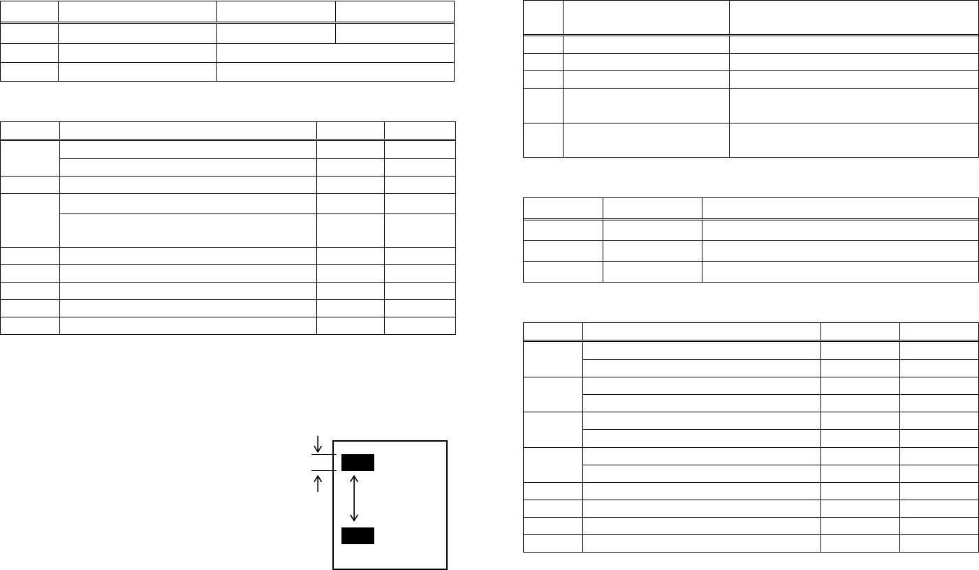
- 234 -
PMU2XXX
n Type of Printer ID Specification Value (Hex.)
1、49 Model ID PMU2XXX 3D
2、50 Type ID Refer to table “Type ID” below
3、51 ROM version ID Differs by ROM version.
Type ID If n = 2, 50 is specified:
Bit Meaning Hex. Decimal
Not equipped for 2 byte code support 00 0
0 Equipped for 2 byte code support 01 1
1 Fixed 00 0
Thermal paper 00 0
2 Black mark paper/ Label paper
(when Black mark paper/ Label paper is selected) 04 4
3 Reserved 00 0
4 Fixed 00 0
5 Reserved 00 0
6 Reserved 00 0
7 Fixed 00 0
n = 4, 52 specified (only for B.M/Label specs)
The Black mark length/label gap length and mark interval/label length
currently used are returned in 4-byte code.All fractional parts in
millimeters are rounded off.
Byte 1 + Byte 2 x256 = Black mark interval
Byte 3 + Byte 4 x256 = Black mark length mm
Black mark paper/Label paper
• Printer information configuration on and after transmitted n=65 is shown
below.
n Kind of Printer
Information Information
65 Firmware version Differs by firmware version.
66 Manufacturer name CITIZEN
67 Model name PMU2XXX
69 Kinds of multi-language
fonts Japanese Kanji specifications: KANJI
112 State of DSW Refer to table “DSW” below
(only serial model)
• Sends printer information specified by n=65 or more.
Hex. Number of Data
Header 5FH 1
Data 20H~7FH Subject to item to be responded
NULL 00H 1
DSW If n = 112 is specified:
Bit Function Hex. Decimal
Dip switch [DSW5] is OFF 00 0
0 Dip switch [DSW5] is ON 01 1
Dip switch [DSW6] is OFF 00 0
1 Dip switch [DSW6] is ON 02 2
Dip switch [DSW7] is OFF 00 0
2 Dip switch [DSW7] is ON 04 4
Dip switch [DSW8] is OFF 00 0
3 Dip switch [DSW8] is ON 08 8
4 Reserved 00 0
5 Reserved 00 0
6 Fixed 40 64
00 0 7 Fixed
*only serial model
(1)
(2)

- 235 -
GS P x y
CT-S280 CT-S300 CT-S2000 CT-S4000 BD2-2220 CT-S310
support model PMU2XXX
[Function] Specifying the basic calculation pitch
[Code] <1D>H<50>H<x><y>
[Range] 0≦x≦255、0≦y≦255
[Outline] [The specification which depend on the model]
• This command sets the horizontal basic calculation pitch to approx. 25.4/x mm (1/x inches), and
the vertical basic calculation pitch to approx. 25.4/y mm (1/y inches).
• If x = 0, the horizontal basic calculation pitch is reverted to the default value.
• If y = 0, the vertical basic calculation pitch is reverted to the default value.
[Caution] • The horizontal direction is defined as the direction perpendicular to the paper feed, and the
vertical direction is defined as the paper feed direction.
• In STANDARD MODE, the following parameters are used regardless of the character orientation
(e.g. inverted or 90°-right-turned).
(1) Commands using x: ESC SP, ESC $, ESC
\
, FS S, GS L, GS W
(2) Commands using y: ESC 3, ESC J
• In PAGE MODE, the parameters used depend on the character orientation, as follows:
(1) If the start point specified by ESC T is the top left or bottom right (The characters are
mapped in the direction perpendicular to the paper feed):
• Commands using x: ESC SP, ESC $, ESC W, ESC
\
, FS S
• Commands using y: ESC 3, ESC J, ESC W, GS $, GS
\
(2) If the start point specified by ESC T is the top right or bottom left (The characters are
mapped in the paper feed direction):
• Commands using x: ESC 3, ESC J, ESC W, GS $, GS
\
• Commands using y: ESC SP, ESC $, ESC W, ESC
\
, FS S
• This command does not affect any other values that are already set.
• If calculations made in combination with another command generate fractions, the fractions are
corrected with the minimum pitch of the mechanism, and the remainder is omitted.
[Default] x=203、y=360
[See Also] Appendix 5.1 “Explanation on PAGE MODE”
ESC SP、ESC $、ESC 3、ESC J、ESC W、ESC
\
、GS $、GS L、GS W

- 236 -
ESC RS
CT-S280 CT-S300 CT-S2000 CT-S4000 BD2-2220 CT-S310
support model PMU2XXX
[Function] Sound buzzer
[Code] <1B>H<1E>H
[Outline] [The specification which depend on the model]
Sound the buzzer for 200 ms.
[Caution] This command is buffered before execution.
CT-S2000/CT-S4000/CT-S310
• Sounds the buzzer when this command is entered even if buzzer is set to disabled with
MSW5-1 OFF.
[Sample Program]
LPRINT CHR$(&H1B); CHR$(&H1E);
[Execution Result]
The buzzer sounds for approx. 200 ms.

- 237 -
3. CHARACTER CODE TABLE
3.1 Code Page
3.1.1 Codepage 00H to 7FH & PC437(USA、Europe Standard)
0 1 2 3 4 5 6 7 8 9 A B C D E F
0 NUL DLE 0 @ P ` p Ç É á ░ └ ╨ α≡
1 XON ! 1 A Q a q ü æ í ▒ ┴ ╤ β ±
2
" 2 B R b r é Æ ó ▓ ┬ ╥ Γ ≧
3 XOFF # 3 C S c s â ô ú │ ├ ╙ π ≦
4 EOT DC4 $ 4 D T d t ä ö ñ ┤ ─ ╘ ∑ ⌠
5 ENQ % 5 E U e u à ò Ñ ╡ ┼ ╒ σ ⌡
6
& 6 F V f v å û a ╢ ╞ ╓ μ ÷
7
' 7 G W g w ç ù o ╖ ╟ ╫ τ ≈
8 CAN ( 8 H X h x ê ÿ ¿ ╕ ╚ ╪ Φ 。
9 HT ) 9 I Y i y ë Ö ⌐ ╣ ╔ ┘ θ
A LF * : J Z j z è Ü ¬ ║ ╩ ┌ Ω ∙
B ESC + ; K [ k { ï ¢ ½ ╗ ╦ █ δ √
C FF FS , < L \ l | î £ ¼ ╝ ╠ ▃ ∞ ⁿ
D CR GS - = M ] m } ì ¥ ¡ ╜ ═ ▌ ∅ ²
E RS
. > N ^ n ~ Ä Pt « ╛ ╬ ▐ ∈ ■
F
/ ? O _ o € Å ƒ » ┐ ╧ ▄ ∩

- 238 -
3.1.2 Codepage 00H to 7FH & Katakana
0 1 2 3 4 5 6 7 8 9 A B C D E F
0 NUL DLE 0 @ P ` p ▁ ┴SP-タ ミ ═ ×
1 XON ! 1 A Q a q ▂ ┬ º ア チ ム ╞ 円
2
" 2 B R b r ▃ ┤┌イツ メ ╪ 年
3 XOFF # 3 C S c s ▅ ├┘ウテ モ ╡ 月
4 EOT DC4 $ 4 D T d t ▆ ─、エト ヤ ◢ 日
5 ENQ % 5 E U e u ▇ _ ・ オ ナ ユ ◣ 時
6
& 6 F V f v █ |ヲカニ ヨ ◥ 分
7
' 7 G W g w ▉ ▕ ァ キ ヌ ラ ◤ 秒
8 CAN ( 8 H X h x ▏ ┌ィクネ リ ♠ 〒
9 HT ) 9 I Y i y ▎ ┐ゥケノ ル ♥ 市
A LF * : J Z j z ▍ └ェコハ レ ♦ 区
B ESC + ; K [ k { ▌ ┘ォサヒ ロ ♣ 町
C FF FS , < L \ l | ▋ ╭ ャ シ フ ワ ● 村
D CR GS - = M ] m } ▋ ╮ ュ ス ヘ ン ○ 人
E RS
. > N ^ n ~ ▊ ╰ ョ セ ホ “ ╱ ▒
F
/ ? O _ o € + ╯ ッ ソ マ ゜ ╲ SP

- 239 -
3.1.3 Codepage 00H to 7FH & PC850(Multilingual)
0 1 2 3 4 5 6 7 8 9 A B C D E F
0 NUL DLE 0 @ P ` p Ç É á ░ └ ð Ó ―
1 XON ! 1 A Q a q ü æ í ▒ ┴ Ð β ±
2
" 2 B R b r é Æ ó ▓ ┬ Ê Ô =
3 XOFF # 3 C S c s â ô ú │ ├ Ë Ò ¾
4 EOT DC4 $ 4 D T d t ä ö ñ ┤ ─ È õ ¶
5 ENQ % 5 E U e u à ò Ñ Á ┼ € Õ §
6
& 6 F V f v å û a  ã Í μ ÷
7
' 7 G W g w ç ù o À Ã Î þ ゝ
8 CAN ( 8 H X h x ê ÿ ¿ © ╚ Ï Þ °
9 HT ) 9 I Y i y ë Ö ® ╣ ╔ ┘ Ú ¨
A LF * : J Z j z è Ü ¬ ║ ╩ ┌ Û ∙
B ESC + ; K [ k { ï ø ½ ╗ ╦ █ Ù ¹
C FF FS , < L \ l | î £ ¼ ╝ ╠ ▃ ý ³
D CR GS - = M ] m } ì Ø ¡ ¢ ═ ¦ Ý ₂
E RS
. > N ^ n ~ Ä × « \ ╬ Ì ― ■
F
/ ? O _ o € Å ƒ » ┐ ¤ ▄ ′
- 240 -
3.1.4 Codepage 00H to 7FH & PC860(Portuguese)
0 1 2 3 4 5 6 7 8 9 A B C D E F
0 NUL DLE 0 @ P ` p Ç É á ░ └ ╨ α≡
1 XON ! 1 A Q a q ü À í ▒ ┴ ╤ β ±
2
" 2 B R b r é È ó ▓ ┬ ╥ Γ ≧
3 XOFF # 3 C S c s â ô ú │ ├ ╙ π ≦
4 EOT DC4 $ 4 D T d t ã õ ñ ┤ ─ ╘ ∑ ⌠
5 ENQ % 5 E U e u à ò Ñ ╡ ┼ ╒ σ ⌡
6
& 6 F V f v Á Ú a ╢ ╞ ╓ μ ÷
7
' 7 G W g w ç ù o ╖ ╟ ╫ τ ≈
8 CAN ( 8 H X h x ê Ì ¿ ╕ ╚ ╪ Φ °
9 HT ) 9 I Y i y Ê Õ Ò ╣ ╔ ┘ θ
A LF * : J Z j z è Ü ¬ ║ ╩ ┌ Ω ∙
B ESC + ; K [ k { Í ¢ ½ ╗ ╦ █ δ √
C FF FS , < L \ l | Ô £ ¼ ╝ ╠ ▃ ∞ ⁿ
D CR GS - = M ] m } ì Ù ¡ ╜ ═ ▌ ∅ ₂
E RS
. > N ^ n ~ Ã Pt « ╛ ╬ ▐ ∈ ■
F
/ ? O _ o € Â Ó » ┐ ╧ ▄ ∩

- 241 -
3.1.5 Codepage 00H to 7FH & PC863(Canadian-French)
0 1 2 3 4 5 6 7 8 9 A B C D E F
0 NUL DLE 0 @ P ` p Ç É ¦ ░ └ ╨ α≡
1 XON ! 1 A Q a q ü È ´ ▒ ┴ ╤ β ±
2
" 2 B R b r é Ê ô ▓ ┬ ╥ Γ ≧
3 XOFF # 3 C S c s â ô ú │ ├ ╙ π ≦
4 EOT DC4 $ 4 D T d t Â Ë ¨ ┤ ─ ╘ ∑ ⌠
5 ENQ % 5 E U e u à Ï ゝ╡ ┼ ╒ σ ⌡
6
& 6 F V f v ¶ û ³ ╢ ╞ ╓ μ ÷
7
' 7 G W g w ç ù - ╖ ╟ ╫ τ ≈
8 CAN ( 8 H X h x ê ¤ Î ╕ ╚ ╪ Φ 。
9 HT ) 9 I Y i y ë Ô ⌐ ╣ ╔ ┘ θ
A LF * : J Z j z è Ü ¬ ║ ╩ ┌ Ω ∙
B ESC + ; K [ k { Ï ¢ ½ ╗ ╦ █ δ √
C FF FS , < L \ l | Î £ ¼ ╝ ╠ ▃ ∞ ⁿ
D CR GS - = M ] m } = Ù ¾ ╜ ═ ▌ ∅ ²
E RS
. > N ^ n ~ À Û « ╛ ╬ ▐ ∈ ■
F
/ ? O _ o € § ƒ » ┐ ╧ ▄ ∩

- 242 -
3.1.6 Codepage 00H to 7FH & PC865(Nordic)
0 1 2 3 4 5 6 7 8 9 A B C D E F
0 NUL DLE 0 @ P ` p Ç É á ░ └ ╨ α≡
1 XON ! 1 A Q a q ü æ í ▒ ┴ ╤ β ±
2
" 2 B R b r é Æ ó ▓ ┬ ╥ Γ ≧
3 XOFF # 3 C S c s â ô ú │ ├ ╙ π ≦
4 EOT DC4 $ 4 D T d t ä ö ñ ┤ ─ ╘ ∑ ⌠
5 ENQ % 5 E U e u à ò Ñ ╡ ┼ ╒ σ ⌡
6
& 6 F V f v å û a ╢ ╞ ╓ μ ÷
7
' 7 G W g w ç ù o ╖ ╟ ╫ τ ≈
8 CAN ( 8 H X h x ê ÿ ¿ ╕ ╚ ╪ Φ 。
9 HT ) 9 I Y i y ë Ö ⌐ ╣ ╔ ┘ θ
A LF * : J Z j z è Ü ¬ ║ ╩ ┌ Ω ∙
B ESC + ; K [ k { Ï ø ½ ╗ ╦ █ δ √
C FF FS , < L \ l | Î £ ¼ ╝ ╠ ▃ ∞ ⁿ
D CR GS - = M ] m } Ì Ø ¡ ╜ ═ ▌ ∅ ₂
E RS
. > N ^ n ~ Ä Pt « ╛ ╬ ▐ ∈ ■
F
/ ? O _ o € Å ƒ ¤ ┐ ╧ ▄ ∩

- 243 -
3.1.7 Codepage 00H to 7FH & PC852(Easern Europe)
0 1 2 3 4 5 6 7 8 9 A B C D E F
0 NUL DLE 0 @ P ` p Ç É á ░ └ đ Ó -
1 XON ! 1 A Q a q ü Ĺ í ▒ ┴ Đ β ”
2
" 2 B R b r é Í ó ▓ ┬ Ď Ó 、
3 XOFF # 3 C S c s â Ú ú │ ├ Ë Ń ˇ
4 EOT DC4 $ 4 D T d t ä Ö Ą ┤ ─ ď Ń ˘
5 ENQ % 5 E U e u ů Ľ ą Á ┼ Ň Ň §
6
& 6 F V f v ć Ĭ Ž Â Ă Í Š ÷
7
' 7 G W g w ç Ś ž Ě Ă î Š ゝ
8 CAN ( 8 H X h x ł Ś Ę Ş ╚ ĕ Ŕ ゚
9 HT ) 9 I Y i y ë Ö ę ╣ ╔ ┘ Ú ¨
A LF * : J Z j z Ő Ü ť ║ ╩ ┌ Ŕ ∙
B ESC + ; K [ k { ő Ť ź ╗ ╦ █ Ű ű
C FF FS , < L \ l | î Č ╝ ╠ ▃ Ý Ř
D CR GS - = M ] m } Ź Ł ş Ż ═ Ţ Ý ř
E RS
. > N ^ n ~ Ä × « Ż ╬ Ů Ţ ■
F
/ ? O _ o € Ć Č » ┐ ¤ ▀ ´ SP

- 244 -
3.1.8 Codepage 00H to 7FH & PC857(Russian)
0 1 2 3 4 5 6 7 8 9 A B C D E F
0 NUL DLE 0 @ P ` p ΑРа ░ └ ╨ р Ë
1 XON ! 1 A Q a q Б С б ▒ ┴ ╤ с ë
2
" 2 B R b r В Т в ▓ ┬ ╥ т Є
3 XOFF # 3 C S c s ГУг│├ ╙ у є
4 EOT DC4 $ 4 D T d t ДФд┤─ ╘ ф Ї
5 ENQ % 5 E U e u Е Х е ╡ ┼ ╒ ц ї
6
& 6 F V f v Ж Ц ж ╢ ╞ ╓ ц ў
7
' 7 G W g w З Ч з ╖ ╟ ╫ ч
8 CAN ( 8 H X h x И Ш и ╕ ╚ ╪ х ゚
9 HT ) 9 I Y i y Й Щ й ╣ ╔ ┘ ш ⦆
A LF * : J Z j z К Ъ к ║ ╩ ┌ щ ∙
B ESC + ; K [ k { Л Ы л ╗ ╦ █ ъ ű
C FF FS , < L \ l | М Ь м ╝ ╠ ▃ ы No.
D CR GS - = M ] m } Н Э н ╜ ═ Ţ э ¤
E RS
. > N ^ n ~ О Ю о ╛ ╬ Ů ю ■
F
/ ? O _ o € ПЯп┐ ╧ ▀ я

- 245 -
3.1.9 Codepage 00H to 7FH & PC857(Turkish)
0 1 2 3 4 5 6 7 8 9 A B C D E F
0 NUL DLE 0 @ P ` p Ç É á ░ └ o ó ―
1 XON ! 1 A Q a q ü æ í ▒ ┴ a β±
2
" 2 B R b r é Æ ó ▓ ┬ Ê ô
3 XOFF # 3 C S c s â ô ú │ ├ Ë ò ¾
4 EOT DC4 $ 4 D T d t à ö ñ ┤ ─ È õ ¶
5 ENQ % 5 E U e u ä ò Ñ Á ┼ Õ §
6
& 6 F V f v å û Ĝ Â ã Í μ ÷
7
' 7 G W g w ç ù ĝ À Ã Î ゝ
8 CAN ( 8 H X h x ê Í ¿ © ╚ Ï × ゚
9 HT ) 9 I Y i y ë Ö ® ╣ ╔ ┘ Ú ¨
A LF * : J Z j z è Ü ¬ ║ ╩ ┌ Û .
B ESC + ; K [ k { ï ø ½ ╗ ╦ █ Ù ¹
C FF FS , < L \ l | î £ ¼ ╝ ╠ ▃ Ì ³
D CR GS - = M ] m } I Ø ¡ ¢ ═ ¦ ÿ ²
E RS
. > N ^ n ~ Ä Ş « ¥ ╬ Ì - ■
F
/ ? O _ o € Å ş » ┐ ¤ ▀ ´ SP
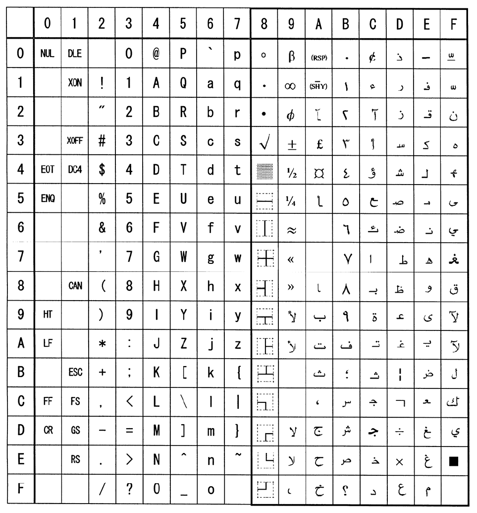
- 246 -
3.1.10 Codepage 00H to 7FH & PC864(ArabiC)

- 247 -
3.1.11 Codepage 00H to 7FH & Windows Codepage
0 1 2 3 4 5 6 7 8 9 A B C D E F
0 NUL DLE 0 @ P ` p ° À Ð à ð
1 XON ! 1 A Q a q ‘ ¡ ± Á Ñ á ñ
2
" 2 B R b r ¸ ’ ¢ ² Â Ò â ò
3 XOFF # 3 C S c s ƒ “ £ ³ Ã Ó ã ó
4 EOT DC4 $ 4 D T d t ,, ” ¤ ´ Ä Ô ä Ô
5 ENQ % 5 E U e u ... ‧ ¥ µ Å Õ å Õ
6
& 6 F V f v ‐ ¦ ¶ Æ Ö æ ö
7
' 7 G W g w ‒ § · Ç × ç ÷
8 CAN ( 8 H X h x ~ ¨ ¸ È Ø è ø
9 HT ) 9 I Y i y ‰ ™ © ¹ É Ù é ù
A LF * : J Z j z Š š ª º Ê Ú ê ú
B ESC + ; K [ k { ‹ › « » Ë Û ë û
C FF FS , < L \ l | Œ œ ¬ ¼ Ì Ü ì ü
D CR GS - = M ] m } ½ Í Ý í ý
E RS
. > N ^ n ~ ® ¾ Î Þ î þ
F
/ ? O _ o € Ÿ ¯ ¿ Ï ß ï ÿ

- 248 -
3.1.12 Codepage 00H to 7FH & Thai code 18
- 249 -
3.2 Internatinal Character Code Table
Country 23 24 40 5B 5C 5D 5E 60 7B 7C 7D 7E
0 U.S.A # $ @ [ ╲ ] ^ ' { | } ~
1 France # $ à ° ç § ^ ' é ù è ¨
2 Germany # $ § Ä Ö Ü ^ ' ä ö ö β
3 U.K. £ $ @ [ ╲ ] ^ ' { | } ~
4 Denmark I # $ @ Æ Ø Å ^ ' æ ø å ~
5 Sweden # ¤ É Ä Ö Å Ü é ä ö å ü
6 Italy # $ @ ° ╲ é ^ ù à ò è ì
7 Spain I Pt $ @ ¡ Ñ ¿ ^ ' ¨ ñ } ~
8 Japan # $ @ [ ¥ ] ^ ' { | } ~
9 Norway # ¤ É Æ Ø Å Ü é æ ø å ü
10 Denmark II # $ É Æ Ø Å Ü é æ ø å ü
11 Spain II # $ á ¡ Ñ ¿ é ' ì ñ ó ú
12 Latin America # $ á ¡ Ñ ¿ é ü ì ñ ó ú
13 Korea # $ @ [ ₩ ] ^ ' { | } ~
14 Croatia # $ Ž Š Đ Ć Č ž š đ ć č
15 China # ¥ @ [ ╲ ] ^ ' { | } ~
- 250 -
3.3 Kanji Code Table
3.3.1 JIS non-Kanji
S-JIS JIS 0 1 2 3 4 5 6 7 8 9 A B C D E F
813F 2120 、 。 ,.・:;?!゛ ゜ ´ `¨
814F 2130 ^  ̄_ ヽ ヾゝゞ〃仝〆〇〇 ― ― ‐/
815F 2140 \ ~∥ | …‥‘’“”() 〔 〕 []
816F 2150 { }〈 〉 《》「」『』【】 + - ±×
8180 2160 ÷ =≠ < >≦≧∞∴♂♀° ′ ″ ℃¥
8190 2170 $ ¢ £ % # & * @ § ☆ ★ ○ ● ◎ ◇
819E 2220 ◆□ ■ △▲▽▼※〒→← ↑ ↓ 〓
81AE 2230 ∈∋ ⊆ ⊇ ⊂⊃
81BE 2240 ∪ ∩ ∧∨ ¬ ⇒ ⇔∀
81CE 2250 ∃ ∠ ⊥ ⌒∂
81DE 2260 ∇ ≡≒ ≪ ≫√∽∝∵∫∬
81EE 2270 Å ‰ ♯ ♭ ♪ † ‡ ¶ ◯
823F 2320
824F 2330 0 12 3 456789
825F 2340 AB C DEFGHIJK L M NO
826F 2350 P QR S TUVWXYZ
8280 2360 ab c defghijk l m no
8290 2370 p qr s tuvwxyz
829E 2420 ぁあ ぃ いぅうぇえぉおか が き ぎく
82AE 2430 ぐ けげ こ ごさざしじすずせ ぜ そ ぞた
82BE 2440 だ ちぢ っ つづてでとどなに ぬ ね のは
82CE 2450 ば ぱひ び ぴふぶぷへべぺほ ぼ ぽ まみ
82DE 2460 む めも ゃ やゅゆょよらりる れ ろ ゎわ
82EE 2470 ゐ ゑを ん
833F 2520 ァア ィ イゥウェエォオカ ガ キ ギク
834F 2530 グ ケゲ コ ゴサザシジスズセ ゼ ソ ゾタ
835F 2540 ダ チヂ ッ ツヅテデトドナニ ヌ ネ ノハ
836F 2550 バ パヒ ビ ピフブプヘベペホ ボ ポ マミ
8380 2560 ム メモ ャ ヤュユョヨラリル レ ロ ヮワ
8390 2570 ヰ ヱヲ ン ヴヵヶ
839E 2620 ΑΒ Γ ΔΕΖΗΘΙΚΛ Μ Ν ΞΟ
83AE 2630 Π ΡΣ Τ ΥΦΧΨΩ
83BE 2640 αβ γ δεζηθικλ μ ν ξο
83CE 2650 π ρσ τ υφχψω
83DE 2660
83EE 2670

- 251 -
S-JIS JIS 0 1 2 3 4 5 6 7 8 9 A B C D E F
843F 2720 А Б В ГДЕЁЖЗИЙ К Л МН
844F 2730 О П Р С Т У Ф Х Ц Ч Ш Щ Ъ Ы Ь Э
845F 2740 Ю Я
846F 2750 а б в гдеёжзий к л мн
8480 2760 о п р с т у ф х ц ч ш щ ъ ы ь э
8490 2770 ю я
849E 2820 ─ │ ┌ ┐┘└├┬┤┴┼ ━ ┃ ┏┓
84AE 2830 ┛ ┗ ┣ ┳ ┫ ┻ ╋ ┠ ┯ ┨ ┷ ┿ ┝ ┰ ┥ ┸
84BE 2840 ╂
84CE 2850
84DE 2860
84EE 2870
- 252 -
3.3.2 JIS Kanji Level 1
S-JIS JIS 0 1 2 3 4 5 6 7 8 9 A B C D E F
889E 3020 亜唖 娃 阿哀愛挨姶逢葵茜 穐 悪 握渥
88AE 3030 旭 葦芦 鯵 梓圧斡扱宛姐虻飴 絢 綾 鮎或
88BE 3040 粟 袷安 庵 按暗案闇鞍杏以伊 位 依 偉囲
88CE 3050 夷 委威 尉 惟意慰易椅為畏異 移 維 緯胃
88DE 3060 萎 衣謂 違 遺医井亥域育郁磯 一 壱 溢逸
88EE 3070 稲 茨芋 鰯 允印咽員因姻引飲 淫 胤 蔭
893F 3120 院陰 隠 韻吋右宇烏羽迂雨 卯 鵜 窺丑
894F 3130 碓 臼渦 嘘 唄欝蔚鰻姥厩浦瓜 閏 噂 云運
895F 3140 雲 荏餌 叡 営嬰影映曳栄永泳 洩 瑛 盈穎
896F 3150 頴 英衛 詠 鋭液疫益駅悦謁越 閲 榎 厭円
8980 3160 園 堰奄 宴 延怨掩援沿演炎焔 煙 燕 猿縁
8990 3170 艶 苑薗 遠 鉛鴛塩於汚甥凹央 奥 往 応
899E 3220 押旺 横 欧殴王翁襖鴬鴎黄 岡 沖 荻億
89AE 3230 屋 憶臆 桶 牡乙俺卸恩温穏音 下 化 仮何
89BE 3240 伽 価佳 加 可嘉夏嫁家寡科暇 果 架 歌河
89CE 3250 火 珂禍 禾 稼箇花苛茄荷華菓 蝦 課 嘩貨
89DE 3260 迦 過霞 蚊 俄峨我牙画臥芽蛾 賀 雅 餓駕
89EE 3270 介 会解 回 塊壊廻快怪悔恢懐 戒 拐 改
8A3F 3320 魁晦 械 海灰界皆絵芥蟹開 階 貝 凱劾
8A4F 3330 外 咳害 崖 慨概涯碍蓋街該鎧 骸 浬 馨蛙
8A5F 3340 垣 柿蛎 鈎 劃嚇各廓拡撹格核 殻 獲 確穫
8A6F 3350 覚 角赫 較 郭閣隔革学岳楽額 顎 掛 笠樫
8A80 3360 橿 梶鰍 潟 割喝恰括活渇滑葛 褐 轄 且鰹
8A90 3370 叶 椛樺 鞄 株兜竃蒲釜鎌噛鴨 栢 茅 萱
8A9E 3420 粥刈 苅 瓦乾侃冠寒刊勘勧 巻 喚 堪姦
8AAE 3430 完 官寛 干 幹患感慣憾換敢柑 桓 棺 款歓
8ABE 3440 汗 漢澗 潅 環甘監看竿管簡緩 缶 翰 肝艦
8ACE 3450 莞 観諌 貫 還鑑間閑関陥韓館 舘 丸 含岸
8ADE 3460 巌 玩癌 眼 岩翫贋雁頑顔願企 伎 危 喜器
8AEE 3470 基 奇嬉 寄 岐希幾忌揮机旗既 期 棋 棄
8B3F 3520 機帰 毅 気汽畿祈季稀紀徽 規 記 貴起
8B4F 3530 軌 輝飢 騎 鬼亀偽儀妓宜戯技 擬 欺 犠疑
8B5F 3540 祇 義蟻 誼 議掬菊鞠吉吃喫桔 橘 詰 砧杵
8B6F 3550 黍 却客 脚 虐逆丘久仇休及吸 宮 弓 急救
8B80 3560 朽 求汲 泣 灸球究窮笈級糾給 旧 牛 去居
8B90 3570 巨 拒拠 挙 渠虚許距鋸漁禦魚 亨 享 京
- 253 -
S-JIS JIS 0 1 2 3 4 5 6 7 8 9 A B C D E F
8B9E 3620 供 侠 僑 兇 競 共 凶 協 匡 卿 叫 喬 境 峡 強
8BAE 3630 彊 怯 恐 恭 挟 教 橋 況 狂 狭 矯 胸 脅 興 蕎 郷
8BBE 3640 鏡 響 饗 驚 仰 凝 尭 暁 業 局 曲 極 玉 桐 粁 僅
8BCE 3650 勤 均 巾 錦 斤 欣 欽 琴 禁 禽 筋 緊 芹 菌 衿 襟
8BDE 3660 謹 近 金 吟 銀 九 倶 句 区 狗 玖 矩 苦 躯 駆 駈
8BEE 3670 駒 具 愚 虞 喰 空 偶 寓 遇 隅 串 櫛 釧 屑 屈
8C3F 3720 掘 窟 沓 靴 轡 窪 熊 隈 粂 栗 繰 桑 鍬 勲 君
8C4F 3730 薫 訓 群 軍 郡 卦 袈 祁 係 傾 刑 兄 啓 圭 珪 型
8C5F 3740 契 形 径 恵 慶 慧 憩 掲 携 敬 景 桂 渓 畦 稽 系
8C6F 3750 経 継 繋 罫 茎 荊 蛍 計 詣 警 軽 頚 鶏 芸 迎 鯨
8C80 3760 劇 戟 撃 激 隙 桁 傑 欠 決 潔 穴 結 血 訣 月 件
8C90 3770 倹 倦 健 兼 券 剣 喧 圏 堅 嫌 建 憲 懸 拳 捲
C89E 3820 検 権 牽 犬 献 研 硯 絹 県 肩 見 謙 賢 軒 遣
8CAE 3830 鍵 険 顕 験 鹸 元 原 厳 幻 弦 減 源 玄 現 絃 舷
8CBE 3840 言 諺 限 乎 個 古 呼 固 姑 孤 己 庫 弧 戸 故 枯
8CCE 3850 湖 狐 糊 袴 股 胡 菰 虎 誇 跨 鈷 雇 顧 鼓 五 互
8CDE 3860 伍 午 呉 吾 娯 後 御 悟 梧 檎 瑚 碁 語 誤 護 醐
8CEE 3870 乞 鯉 交 佼 侯 候 倖 光 公 功 効 勾 厚 口 向
8D3F 3920 后 喉 坑 垢 好 孔 孝 宏 工 巧 巷 幸 広 庚 康
8D4F 3930 弘 恒 慌 抗 拘 控 攻 昂 晃 更 杭 校 梗 構 江 洪
8D5F 3940 浩 港 溝 甲 皇 硬 稿 糠 紅 紘 絞 綱 耕 考 肯 肱
8D6F 3950 腔 膏 航 荒 行 衡 講 貢 購 郊 酵 鉱 砿 鋼 閤 降
8D80 3960 項 香 高 鴻 剛 黒 号 合 壕 拷 濠 豪 轟 麹 克 刻
8D90 3970 告 国 穀 酷 鵠 黒 獄 漉 腰 甑 忽 惚 骨 狛 込
8D9E 3A20 此 頃 今 困 坤 墾 婚 恨 懇 昏 昆 根 梱 混 痕
8DAE 3A30 紺 艮 魂 些 佐 叉 唆 嵯 左 差 査 沙 瑳 砂 詐 鎖
8DBE 3A40 裟 坐 座 挫 債 催 再 最 哉 塞 妻 宰 彩 才 採 栽
8DCE 3A50 歳 済 災 采 犀 砕 砦 祭 斎 細 崎 裁 載 際 剤 在
8DDE 3A60 材 罪 財 冴 坂 阪 堺 榊 肴 咲 崎 埼 碕 鷺 作 削
8DEE 3A70 咋 搾 昨 朔 柵 窄 策 索 錯 桜 鮭 笹 匙 冊 刷
8E3F 3B20 察 拶 撮 擦 札 殺 薩 雑 皐 鯖 捌 錆 鮫 皿 晒
8E4F 3B30 三 傘 参 山 惨 撒 散 桟 燦 珊 産 算 纂 蚕 讃 賛
8E5F 3B40 酸 餐 斬 暫 残 仕 仔 伺 使 刺 司 史 嗣 四 士 始
8E6F 3B50 姉 姿 子 屍 市 師 志 思 指 支 孜 斯 施 旨 枝 止
8E80 3B60 死 氏 獅 祉 私 糸 紙 紫 肢 脂 至 視 詞 詩 試 誌
8E90 3B70 諮 資 賜 雌 飼 歯 事 似 侍 児 字 寺 慈 持 時
- 254 -
S-JIS JIS 0 1 2 3 4 5 6 7 8 9 A B C D E F
8E9E 3C20 次 滋 治 爾璽痔磁示而耳自 蒔 辞 汐鹿
8EAE 3C30 式 識 鴫 竺 軸 宍 雫 七 叱 執 失 嫉 室 悉 湿 漆
8EBE 3C40 疾 質 実 蔀 篠 偲 柴 芝 屡 蕊 縞 舎 写 射 捨 赦
8ECE 3C50 斜 煮 社 紗 者 謝 車 遮 蛇 邪 借 勺 尺 杓 灼 爵
8EDE 3C60 酌 釈 錫 若 寂 弱 惹 主 取 守 手 朱 殊 狩 珠 種
8EEE 3C70 腫 趣 酒 首 儒 受 呪 寿 授 樹 綬 需 囚 収 周
8F3F 3D20 宗 就 州 修愁拾洲秀秋終繍 習 臭 舟蒐
8F4F 3D30 衆 襲 讐 蹴 輯 週 酋 酬 集 醜 什 住 充 十 従 戎
8F5F 3D40 柔 汁 渋 獣 縦 重 銃 叔 夙 宿 淑 祝 縮 粛 塾 熟
8F6F 3D50 出 術 述 俊 峻 春 瞬 竣 舜 駿 准 循 旬 楯 殉 淳
8F80 3D60 準 潤 盾 純 巡 遵 醇 順 処 初 所 暑 曙 渚 庶 緒
8F90 3D70 署 書 薯 藷 諸 助 叙 女 序 徐 恕 鋤 除 傷 償
8F9E 3E20 勝 匠 升 召哨商唱嘗奨妾娼 宵 将 小少
8FAE 3E30 尚 庄 床 廠 彰 承 抄 招 掌 捷 昇 昌 昭 晶 松 梢
8FBE 3E40 樟 樵 沼 消 渉 湘 焼 焦 照 症 省 硝 礁 祥 称 章
8FCE 3E50 笑 粧 紹 肖 菖 蒋 蕉 衝 裳 訟 証 詔 詳 象 賞 醤
8FDE 3E60 鉦 鍾 鐘 障 鞘 上 丈 丞 乗 冗 剰 城 場 壌 嬢 常
8FEE 3E70 情 擾 条 杖 浄 状 畳 穣 蒸 譲 醸 錠 嘱 埴 飾
903F 3F20 拭 植 殖 燭織職色触食蝕辱 尻 伸 信侵
904F 3F30 唇 娠 寝 審 心 慎 振 新 晋 森 榛 浸 深 申 疹 真
905F 3F40 神 秦 紳 臣 芯 薪 親 診 身 辛 進 針 震 人 仁 刃
906F 3F50 塵 壬 尋 甚 尽 腎 訊 迅 陣 靭 笥 諏 須 酢 図 厨
9080 3F60 逗 吹 垂 帥 推 水 炊 睡 粋 翠 衰 遂 酔 錐 錘 随
9090 3F70 瑞 髄 崇 嵩 数 枢 趨 雛 据 杉 椙 菅 頗 雀 裾
909E 4020 澄 摺 寸 世瀬畝是凄制勢姓 征 性 成政
90AE 4030 整 星 晴 棲 栖 正 清 牲 生 盛 精 聖 声 製 西 誠
90BE 4040 誓 請 逝 醒 青 静 斉 税 脆 隻 席 惜 戚 斥 昔 析
90CE 4050 石 積 籍 績 脊 責 赤 跡 蹟 碩 切 拙 接 摂 折 設
90DE 4060 窃 節 説 雪 絶 舌 蝉 仙 先 千 占 宣 専 尖 川 戦
90EE 4070 扇 撰 栓 栴 泉 浅 洗 染 潜 煎 煽 旋 穿 箭 線
913F 4120 繊 羨 腺 舛船薦詮賎践選遷 銭 銑 閃鮮
914F 4130 前 善 漸 然 全 禅 繕 膳 糎 噌 塑 岨 措 曾 曽 楚
915F 4140 狙 疏 疎 礎 祖 租 粗 素 組 蘇 訴 阻 遡 鼠 僧 創
916F 4150 双 叢 倉 喪 壮 奏 爽 宋 層 匝 惣 想 捜 掃 挿 掻
9180 4160 操 早 曹 巣 槍 槽 漕 燥 争 痩 相 窓 糟 総 綜 聡
9190 4170 草 荘 葬 蒼 藻 装 走 送 遭 鎗 霜 騒 像 増 憎
- 255 -
S-JIS JIS 0 1 2 3 4 5 6 7 8 9 A B C D E F
919E 4220 臓蔵 贈 造促側則即息捉束 測 足 速俗
91AE 4230 属 賊族 続 卒袖其揃存孫尊損 村 遜 他多
91BE 4240 太 汰詑 唾 堕妥惰打柁舵楕陀 駄 騨 体堆
91CE 4250 対 耐岱 帯 待怠態戴替泰滞胎 腿 苔 袋貸
91DE 4260 退 逮隊 黛 鯛代台大第醍題鷹 滝 瀧 卓啄
91EE 4270 宅 托択 拓 沢濯琢託鐸濁諾茸 凧 蛸 只
923F 4320 叩但 達 辰奪脱巽竪辿棚谷 狸 鱈 樽誰
924F 4330 丹 単嘆 坦 担探旦歎淡湛炭短 端 箪 綻耽
925F 4340 胆 蛋誕 鍛 団壇弾断暖檀段男 談 値 知地
926F 4350 弛 恥智 池 痴稚置致蜘遅馳築 畜 竹 筑蓄
9280 4360 逐 秩窒 茶 嫡着中仲宙忠抽昼 柱 注 虫衷
9290 4370 註 酎鋳 駐 樗瀦猪苧著貯丁兆 凋 喋 寵
929E 4420 帖帳 庁 弔張彫徴懲挑暢朝 潮 牒 町眺
92AE 4430 聴 脹腸 蝶 調諜超跳銚長頂鳥 勅 捗 直朕
92BE 4440 沈 珍賃 鎮 陳津墜椎槌追鎚痛 通 塚 栂掴
92CE 4450 槻 佃漬 柘 辻蔦綴鍔椿潰坪壷 嬬 紬 爪吊
92DE 4460 釣 鶴亭 低 停偵剃貞呈堤定帝 底 庭 廷弟
92EE 4470 悌 抵挺 提 梯汀碇禎程締艇訂 諦 蹄 逓
933F 4520 邸鄭 釘 鼎泥摘擢敵滴的笛 適 鏑 溺哲
934F 4530 徹 撤轍 迭 鉄典填天展店添纏 甜 貼 転顛
935F 4540 点 伝殿 澱 田電兎吐堵塗妬屠 徒 斗 杜渡
936F 4550 登 菟賭 途 都鍍砥砺努度土奴 怒 倒 党冬
9380 4560 凍 刀唐 塔 塘套宕島嶋悼投搭 東 桃 梼棟
9390 4570 盗 淘湯 涛 灯燈当痘祷等答筒 糖 統 到
939E 4620 董蕩 藤 討謄豆踏逃透鐙陶 頭 騰 闘働
93AE 4630 動 同堂 導 憧撞洞瞳童胴萄道 銅 峠 鴇匿
93BE 4640 得 徳涜 特 督禿篤毒独読栃橡 凸 突 椴届
93CE 4650 鳶 苫寅 酉 瀞噸屯惇敦沌豚遁 頓 呑 曇鈍
93DE 4660 奈 那内 乍 凪薙謎灘捺鍋楢馴 縄 畷 南楠
93EE 4670 軟 難汝 二 尼弐迩匂賑肉虹廿 日 乳 入
943F 4720 如尿 韮 任妊忍認濡禰祢寧 葱 猫 熱年
944F 4730 念 捻撚 燃 粘乃廼之埜嚢悩濃 納 能 脳膿
945F 4740 農 覗蚤 巴 把播覇杷波派琶破 婆 罵 芭馬
946F 4750 俳 廃拝 排 敗杯盃牌背肺輩配 倍 培 媒梅
9480 4760 楳 煤狽 買 売賠陪這蝿秤矧萩 伯 剥 博拍
9490 4770 柏 泊白 箔 粕舶薄迫曝漠爆縛 莫 駁 麦

- 256 -
S-JIS JIS 0 1 2 3 4 5 6 7 8 9 A B C D E F
949E 4820 函 箱 硲 箸肇筈櫨幡肌畑畠 八 鉢 溌発
94AE 4830 醗 髪 伐 罰 抜 筏 閥 鳩 噺 塙 蛤 隼 伴 判 半 反
94BE 4840 叛 帆 搬 斑 板 氾 汎 版 犯 班 畔 繁 般 藩 販 範
94CE 4850 釆 煩 頒 飯 挽 晩 番 盤 磐 蕃 蛮 匪 卑 否 妃 庇
94DE 4860 彼 悲 扉 批 披 斐 比 泌 疲 皮 碑 秘 緋 罷 肥 被
94EE 4870 誹 費 避 非 飛 樋 簸 備 尾 微 枇 毘 琵 眉 美
953F 4920 鼻 柊 稗 匹疋髭彦膝菱肘弼 必 畢 筆逼
954F 4930 桧 姫 媛 紐 百 謬 俵 彪 標 氷 漂 瓢 票 表 評 豹
955F 4940 廟 描 病 秒 苗 錨 鋲 蒜 蛭 鰭 品 彬 斌 浜 瀕 貧
956F 4950 賓 頻 敏 瓶 不 付 埠 夫 婦 富 冨 布 府 怖 扶 敷
9580 4960 斧 普 浮 父 符 腐 膚 芙 譜 負 賦 赴 阜 附 侮 撫
9590 4970 武 舞 葡 蕪 部 封 楓 風 葺 蕗 伏 副 復 幅 服
959E 4A20 福 腹 複 覆淵弗払沸仏物鮒 分 吻 噴墳
95AE 4A30 憤 扮 焚 奮 粉 糞 紛 雰 文 聞 丙 併 兵 塀 幣 平
95BE 4A40 弊 柄 並 蔽 閉 陛 米 頁 僻 壁 癖 碧 別 瞥 蔑 箆
95CE 4A50 偏 変 片 篇 編 辺 返 遍 便 勉 娩 弁 鞭 保 舗 鋪
95DE 4A60 圃 捕 歩 甫 補 輔 穂 募 墓 慕 戊 暮 母 簿 菩 倣
95EE 4A70 俸 包 呆 報 奉 宝 峰 峯 崩 庖 抱 捧 放 方 朋
963F 4B20 法 泡 烹 砲縫胞芳萌蓬蜂褒 訪 豊 邦鋒
964F 4B30 飽 鳳 鵬 乏 亡 傍 剖 坊 妨 帽 忘 忙 房 暴 望 某
965F 4B40 棒 冒 紡 肪 膨 謀 貌 貿 鉾 防 吠 頬 北 僕 卜 墨
966F 4B50 撲 朴 牧 睦 穆 釦 勃 没 殆 堀 幌 奔 本 翻 凡 盆
9680 4B60 摩 磨 魔 麻 埋 妹 昧 枚 毎 哩 槙 幕 膜 枕 鮪 柾
9690 4B70 鱒 桝 亦 俣 又 抹 末 沫 迄 侭 繭 麿 万 慢 満
969E 4C20 漫 蔓 味 未魅巳箕岬密蜜湊 蓑 稔 脈妙
96AE 4C30 粍 民 眠 務 夢 無 牟 矛 霧 鵡 椋 婿 娘 冥 名 命
96BE 4C40 明 盟 迷 銘 鳴 姪 牝 滅 免 棉 綿 緬 面 麺 摸 模
96CE 4C50 茂 妄 孟 毛 猛 盲 網 耗 蒙 儲 木 黙 目 杢 勿 餅
96DE 4C60 尤 戻 籾 貰 問 悶 紋 門 匁 也 冶 夜 爺 耶 野 弥
96EE 4C70 矢 厄 役 約 薬 訳 躍 靖 柳 薮 鑓 愉 愈 油 癒
973F 4D20 諭 輸 唯 佑優勇友宥幽悠憂 揖 有 柚湧
974F 4D30 涌 猶 猷 由 祐 裕 誘 遊 邑 郵 雄 融 夕 予 余 与
975F 4D40 誉 輿 預 傭 幼 妖 容 庸 揚 揺 擁 曜 楊 様 洋 溶
976F 4D50 熔 用 窯 羊 耀 葉 蓉 要 謡 踊 遥 陽 養 慾 抑 欲
9780 4D60 沃 浴 翌 翼 淀 羅 螺 裸 来 莱 頼 雷 洛 絡 落 酪
9790 4D70 乱 卵 嵐 欄 濫 藍 蘭 覧 利 吏 履 李 梨 理 璃
- 257 -
S-JIS JIS 0 1 2 3 4 5 6 7 8 9 A B C D E F
979E 4E20 痢 裏 裡 里離陸律率立葎掠 略 劉 流溜
97AE 4E30 琉 留 硫 粒 隆 竜 龍 侶 慮 旅 虜 了 亮 僚 両 凌
97BE 4E40 寮 料 梁 涼 猟 療 瞭 稜 糧 良 諒 遼 量 陵 領 力
97CE 4E50 緑 倫 厘 林 淋 燐 琳 臨 輪 隣 鱗 麟 瑠 塁 涙 累
97DE 4E60 類 令 伶 例 冷 励 嶺 怜 玲 礼 苓 鈴 隷 零 霊 麗
97EE 4E70 齢 暦 歴 列 劣 烈 裂 廉 恋 憐 漣 煉 簾 練 聯
983F 4F20 蓮 連 錬 呂魯櫓炉賂路露労 婁 廊 弄朗
984F 4F30 楼 榔 浪 漏 牢 狼 篭 老 聾 蝋 郎 六 麓 禄 肋 録
985F 4F40 論 倭 和 話 歪 賄 脇 惑 枠 鷲 亙 亘 鰐 詫 藁 蕨
986F 4F50 椀 湾 碗 腕
9880 4F60
9890 4F70
- 258 -
3.3.3 JIS Kanji Level 2
S-JIS JIS 0 1 2 3 4 5 6 7 8 9 A B C D E F
989E 5020 弌丐 丕 个丱丶丼丿乂乖乘 亂 亅 豫亊
98AE 5030 舒 弍于 亞 亟亠亢亰亳亶从仍 仄 仆 仂仗
98BE 5040 仞 仭仟 价 伉佚估佛佝佗佇佶 侈 侏 侘佻
98CE 5050 佩 佰侑 佯 來侖儘俔俟俎俘俛 俑 俚 俐俤
98DE 5060 俥 倚倨 倔 倪倥倅伜俶倡倩倬 俾 俯 們倆
98EE 5070 偃 假會 偕 偐偈做偖偬偸傀傚 傅 傴 傲
993F 5120 僉僊 傳 僂僖僞僥僭僣僮價 僵 儉 儁儂
994F 5130 儖 儕儔 儚 儡儺儷儼儻儿兀兒 兌 兔 兢 竸
995F 5140 兩 兪兮 冀 冂囘册冉冏冑冓冕 冖 冤 冦 冢
996F 5150 冩 冪冫 决 冱冲冰况冽凅凉凛 几 處 凩凭
9980 5160 凰 凵凾 刄 刋刔刎刧刪刮刳刹 剏 剄 剋剌
9990 5170 剞 剔剪 剴 剩剳剿剽劍劔劒剱 劈 劑 辨
999E 5220 辧劬 劭 劼劵勁勍勗勞勣勦 飭 勠 勳勵
99AE 5230 勸 勹匆 匈 甸匍匐匏匕匚匣匯 匱 匳 匸區
99BE 5240 卆 卅丗 卉 卍凖卞卩卮夘卻卷 厂 厖 厠厦
99CE 5250 厥 厮厰 厶 參簒雙叟曼燮叮叨 叭 叺 吁吽
99DE 5260 呀 听吭 吼 吮吶吩吝呎咏呵咎 呟 呱 呷呰
99EE 5270 咒 呻咀 呶 咄咐咆哇咢咸咥咬 哄 哈 咨
9A3F 5320 咫哂 咤 咾咼哘哥哦唏唔哽 哮 哭 哺哢
9A4F 5330 唹 啀啣 啌 售啜啅啖啗唸唳啝 喙 喀 咯喊
9A5F 5340 喟 啻啾 喘 喞單啼喃喩喇喨嗚 嗅 嗟 嗄嗜
9A6F 5350 嗤 嗔嘔 嗷 嘖嗾嗽嘛嗹噎噐營 嘴 嘶 嘲嘸
9A80 5360 噫 噤嘯 噬 噪嚆嚀嚊嚠嚔嚏嚥 嚮 嚶 嚴囂
9A90 5370 嚼 囁囃 囀 囈囎囑囓囗囮囹圀 囿 圄 圉
9A9E 5420 圈國 圍 圓團圖嗇圜圦圷圸 坎 圻 址坏
9AAE 5430 坩 埀垈 坡 坿垉垓垠垳垤垪垰 埃 埆 埔埒
9ABE 5440 埓 堊埖 埣 堋堙堝塲堡塢塋塰 毀 塒 堽塹
9ACE 5450 墅 墹墟 墫 墺壞墻墸墮壅壓壑 壗 壙 壘壥
9ADE 5460 壜 壤壟 壯 壺壹壻壼壽夂夊夐 夛 梦 夥夬
9AEE 5470 夭 夲夸 夾 竒奕奐奎奚奘奢奠 奧 奬 奩
9B3F 5520 奸妁 妝 佞侫妣妲姆姨姜妍 姙 姚 娥娟
9B4F 5530 娑 娜娉 娚 婀婬婉娵娶婢婪媚 媼 媾 嫋嫂
9B5F 5540 媽 嫣嫗 嫦 嫩嫖嫺嫻嬌嬋嬖嬲 嫐 嬪 嬶嬾
9B6F 5550 孃 孅孀 孑 孕孚孛孥孩孰孳孵 學 斈 孺宀
9B80 5560 它 宦宸 寃 寇寉寔寐寤實寢寞 寥 寫 寰寶
9B90 5570 寳 尅將 專 對尓尠尢尨尸尹屁 屆 屎 屓

- 259 -
S-JIS JIS 0 1 2 3 4 5 6 7 8 9 A B C D E F
9B9E 5620 屐 屏 孱 屬屮乢屶屹岌岑岔 妛 岫 岻岶
9BAE 5630 岼 岷 峅 岾 峇 峙 峩 峽 峺 峭 嶌 峪 崋 崕 崗 嵜
9BBE 5640 崟 崛 崑 崔 崢 崚 崙 崘 嵌 嵒 嵎 嵋 嵬 嵳 嵶 嶇
9BCE 5650 嶄 嶂 嶢 嶝 嶬 嶮 嶽 嶐 嶷 嶼 巉 巍 巓 巒 巖 巛
9BDE 5660 巫 已 巵 帋 帚 帙 帑 帛 帶 帷 幄 幃 幀 幎 幗 幔
9BEE 5670 幟 幢 幤 幇 幵 并 幺 麼 广 庠 廁 廂 廈 廐 廏
9C3F 5720 廖 廣 廝 廚廛廢廡廨廩廬廱 廳 廰 廴廸
9C4F 5730 廾 弃 弉 彝 彜 弋 弑 弖 弩 弭 弸 彁 彈 彌 彎 弯
9C5F 5740 彑 彖 彗 彙 彡 彭 彳 彷 徃 徂 彿 徊 很 徑 徇 從
9C6F 5750 徙 徘 徠 徨 徭 徼 忖 忻 忤 忸 忱 忝 悳 忿 怡 恠
9C80 5760 怙 怐 怩 怎 怱 怛 怕 怫 怦 怏 怺 恚 恁 恪 恷 恟
9C90 5770 恊 恆 恍 恣 恃 恤 恂 恬 恫 恙 悁 悍 惧 悃 悚
9C9E 5820 悄 悛 悖 悗悒悧悋惡悸惠惓 悴 忰 悽惆
9CAE 5830 悵 惘 慍 愕 愆 惶 惷 愀 惴 惺 愃 愡 惻 惱 愍 愎
9CBE 5840 慇 愾 愨 愧 慊 愿 愼 愬 愴 愽 慂 慄 慳 慷 慘 慙
9CCE 5850 慚 慫 慴 慯 慥 慱 慟 慝 慓 慵 憙 憖 憇 憬 憔 憚
9CDE 5860 憊 憑 憫 憮 懌 懊 應 懷 懈 懃 懆 憺 懋 罹 懍 懦
9CEE 5870 懣 懶 懺 懴 懿 懽 懼 懾 戀 戈 戉 戍 戌 戔 戛
9D3F 5920 戞 戡 截 戮戰戲戳扁扎扞扣 扛 扠 扨扼
9D4F 5930 抂 抉 找 抒 抓 抖 拔 抃 抔 拗 拑 抻 拏 拿 拆 擔
9D5F 5940 拈 拜 拌 拊 拂 拇 抛 拉 挌 拮 拱 挧 挂 挈 拯 拵
9D6F 5950 捐 挾 捍 搜 捏 掖 掎 掀 掫 捶 掣 掏 掉 掟 掵 捫
9D80 5960 捩 掾 揩 揀 揆 揣 揉 插 揶 揄 搖 搴 搆 搓 搦 搶
9D90 5970 攝 搗 搨 搏 摧 摯 摶 摎 攪 撕 撓 撥 撩 撈 撼
9D9E 5A20 據 擒 擅 擇撻擘擂擱擧舉擠 擡 抬 擣擯
9DAE 5A30 攬 擶 擴 擲 擺 攀 擽 攘 攜 攅 攤 攣 攫 攴 攵 攷
9DBE 5A40 收 攸 畋 效 敖 敕 敍 敘 敞 敝 敲 數 斂 斃 變 斛
9DCE 5A50 斟 斫 斷 旃 旆 旁 旄 旌 旒 旛 旙 无 旡 旱 杲 昊
9DDE 5A60 昃 旻 杳 昵 昶 昴 昜 晏 晄 晉 晁 晞 晝 晤 晧 晨
9DEE 5A70 晟 晢 晰 暃 暈 暎 暉 暄 暘 暝 曁 暹 曉 暾 暼
9E3F 5B20 曄 暸 曖 曚曠昿曦曩曰曵曷 朏 朖 朞朦
9E4F 5B30 朧 霸 朮 朿 朶 杁 朸 朷 杆 杞 杠 杙 杣 杤 枉 杰
9E5F 5B40 枩 杼 杪 枌 枋 枦 枡 枅 枷 柯 枴 柬 枳 柩 枸 柤
9E6F 5B50 柞 柝 柢 柮 枹 柎 柆 柧 檜 栞 框 栩 桀 桍 栲 桎
9E80 5B60 梳 栫 桙 档 桷 桾 梟 梏 梭 梔 條 梛 梃 檮 梹 桴
9E90 5B70 梵 梠 梺 椏 梍 桾 椁 棊 椈 棘 椢 椦 棡 椌 棍

- 260 -
S-JIS JIS 0 1 2 3 4 5 6 7 8 9 A B C D E F
9E9E 5C20 棔 棧 棕 椶椒椄棗棣椥棹棠 棯 椨 椪椚
9EAE 5C30 椣 椡 棆 楹 楷 楜 楸 楫 楔 楾 楮 椹 楴 椽 楙 椰
9EBE 5C40 楡 楞 楝 榁 楪 榲 榮 槐 榿 槁 槓 榾 槎 寨 槊 槝
9ECE 5C50 榻 槃 榧 樮 榑 榠 榜 榕 榴 槞 槨 樂 樛 槿 權 槹
9EDE 5C60 槲 槧 樅 榱 樞 槭 樔 槫 樊 樒 櫁 樣 樓 橄 樌 橲
9EEE 5C70 樶 橸 橇 橢 橙 橦 橈 樸 樢 檐 檍 檠 檄 檢 檣
9F3F 5D20 檗 蘗 檻 櫃櫂檸檳檬櫞櫑櫟 檪 櫚 櫪櫻
9F4F 5D30 欅 蘖 櫺 欒 欖 鬱 欟 欸 欷 盜 欹 飮 歇 歃 歉 歐
9F5F 5D40 歙 歔 歛 歟 歡 歸 歹 歿 殀 殄 殃 殍 殘 殕 殞 殤
9F6F 5D50 殪 殫 殯 殲 殱 殳 殷 殼 毆 毋 毓 毟 毬 毫 毳 毯
9F80 5D60 麾 氈 氓 气 氛 氤 氣 汞 汕 汢 汪 沂 沍 沚 沁 沛
9F90 5D70 汾 汨 汳 沒 沐 泄 泱 泓 沽 泗 泅 泝 沮 沱 沾
9F9E 5E20 沺 泛 泯 泙泪洟衍洶洫洽洸 洙 洵 洳洒
9FAE 5E30 洌 浣 涓 浤 浚 浹 浙 涎 涕 濤 涅 淹 渕 渊 涵 淇
9FBE 5E40 淦 涸 淆 淬 淞 淌 淨 淒 淅 淺 淙 淤 淕 淪 淮 渭
9FCE 5E50 湮 渮 渙 湲 湟 渾 渣 湫 渫 湶 湍 渟 湃 渺 湎 渤
9FDE 5E60 滿 渝 游 溂 溪 溘 滉 溷 滓 溽 溯 滄 溲 滔 滕 溏
9FEE 5E70 溥 滂 溟 潁 漑 灌 滬 滸 滾 漿 滲 漱 滯 漲 滌
E03F 5F20 漾 漓 滷 澆潺潸澁澀潯潛濳 潭 澂 潼潘
E04F 5F30 澎 澑 濂 潦 澳 澣 澡 澤 澹 濆 澪 濟 濕 濬 濔 濘
E05F 5F40 濱 濮 濛 瀉 瀋 濺 瀑 瀁 瀏 濾 瀛 瀚 潴 瀝 瀘 瀟
E06F 5F50 瀰 瀾 瀲 灑 灣 炙 炒 炯 烱 炬 炸 炳 炮 烟 烋 烝
E080 5F60 烙 焉 烽 焜 焙 煥 煕 熈 煦 煢 煌 煖 煬 熏 燻 熄
E090 5F70 熕 熨 熬 燗 熹 熾 燒 燉 燔 燎 燠 燬 燧 燵 燼
E09E 6020 燹 燿 爍 爐爛爨爭爬爰爲爻 爼 爿 牀牆
E0AE 6030 牋 牘 牴 牾 犂 犁 犇 犒 犖 犢 犧 犹 犲 狃 狆 狄
E0BE 6040 狎 狒 狢 狠 狡 狹 狷 倏 猗 猊 猜 猖 猝 猴 猯 猩
E0CE 6050 猥 猾 獎 獏 默 獗 獪 獨 獰 獸 獵 獻 獺 珈 玳 珎
E0DE 6060 玻 珀 珥 珮 珞 璢 琅 瑯 琥 珸 琲 琺 瑕 琿 瑟 瑙
E0EE 6070 瑁 瑜 瑩 瑰 瑣 瑪 瑶 瑾 璋 璞 璧 瓊 瓏 瓔 珱
E13F 6120 瓠 瓣 瓧 瓩瓮瓲瓰瓱瓸瓷甄 甃 甅 甌甎
E14F 6130 甍 甕 畭 甞 甦 甬 甼 畄 畍 畊 畉 畛 畆 畚 畩 畤
E15F 6140 畧 畫 畭 畸 當 疆 疇 畴 疊 疉 疂 疔 疚 疝 疥 疣
E16F 6150 痂 疳 痃 疵 疽 疸 疼 疱 痍 痊 痒 痙 痣 痞 痾 痿
E180 6160 痼 瘁 痰 痺 痲 痳 瘋 瘍 瘉 瘟 瘧 瘠 瘡 瘢 瘤 瘴
E190 6170 瘰 瘻 癇 癈 癆 癜 癘 癡 癢 癨 癩 癪 癧 癬 癰

- 261 -
S-JIS JIS 0 1 2 3 4 5 6 7 8 9 A B C D E F
E19E 6220 癲 癶 癸 發皀皃皈皋皎皖皓 皙 皚 皰皴
E1AE 6230 皸 皹 皺 盂 盍 盖 盒 盞 盡 盥 盧 盪 蘯 盻 眈 眇
E1BE 6240 眄 眩 眤 眞 眥 眦 眛 眷 眸 睇 睚 睨 睫 睛 睥 睿
E1CE 6250 睾 睹 瞎 瞋 瞑 瞠 瞞 瞰 瞶 瞹 瞿 瞼 瞽 瞻 矇 矍
E1DE 6260 矗 矚 矜 矣 矮 矼 砌 砒 礦 砠 礪 硅 碎 硴 碆 硼
E1EE 6270 碚 碌 碣 碵 碪 碯 磑 磆 磋 磔 碾 碼 磅 磊 磬
E23F 6320 磧 磚 磽 磴礇礒礑礙礬礫祀 祠 祗 祟祚
E24F 6330 祕 祓 祺 祿 禊 禝 禧 齋 禪 禮 禳 禹 禺 秉 秕 秧
E25F 6340 秬 秡 秣 稈 稍 稘 稙 稠 稟 禀 稱 稻 稾 稷 穃 穗
E26F 6350 穉 穡 穢 穩 龝 穰 穹 穽 窈 窗 窕 窘 窖 窩 竈 窰
E280 6360 窶 竅 竄 窿 邃 竇 竊 竍 竏 竕 竓 站 竚 竝 竡 竢
E290 6370 竦 竭 竰 笂 笏 笊 笆 笳 笘 笙 笞 笵 笨 笶 筐
E29E 6420 筺 笄 筍 笋筌筅筵筥筴筧筰 筱 筬 筮箝
E2AE 6430 箘 箟 箍 箜 箚 箋 箒 箏 筝 箙 篋 篁 篌 篏 箴 篆
E2BE 6440 篝 篩 簑 簔 篦 篥 籠 簀 簇 簓 篳 篷 簗 簍 篶 簣
E2CE 6450 簧 簪 簟 簷 簫 簽 籌 籃 籔 籏 籀 籐 籘 籟 籤 籖
E2DE 6460 籥 籬 籵 粃 粐 粤 粭 粢 粫 粡 粨 粳 粲 粱 粮 粹
E2EE 6470 粽 糀 糅 糂 糘 糒 糜 糢 鬻 糯 糲 糴 糶 糺 紆
E33F 6520 紂 紜 紕 紊絅絋紮紲紿紵絆 絳 絖 絎絲
E34F 6530 絨 絮 絏 絣 經 綉 絛 綏 絽 綛 綺 綮 綣 綵 緇 綽
E35F 6540 綫 總 綢 綯 緜 綸 綟 綰 緘 緝 緤 緞 緻 緲 緡 縅
E36F 6550 縊 縣 縡 縒 縱 縟 縉 縋 縢 繆 繦 縻 縵 縹 繃 縷
E380 6560 縲 縺 繧 繝 繖 繞 繙 繚 繹 繪 繩 繼 繻 纃 緕 繽
E390 6570 辮 繿 纈 纉 續 纒 纐 纓 纔 纖 纎 纛 纜 缸 缺
E39E 6620 罅 罌 罍 罎罐网罕罔罘罟罠 罨 罩 罧罸
E3AE 6630 羂 羆 羃 羈 羇 羌 羔 羞 羝 羚 羣 羯 羲 羹 羮 羶
E3BE 6640 羸 譱 翅 翆 翊 翕 翔 翡 翦 翩 翳 翹 飜 耆 耄 耋
E3CE 6650 耒 耘 耙 耜 耡 耨 耿 耻 聊 聆 聒 聘 聚 聟 聢 聨
E3DE 6660 聳 聲 聰 聶 聹 聽 聿 肄 肆 肅 肛 肓 肚 肭 冐 肬
E3EE 6670 胛 胥 胙 胝 胄 胚 胖 脉 胯 胱 脛 脩 脣 脯 腋
E43F 6720 隋 腆 脾 腓腑胼腱腮腥腦腴 膃 膈 膊膀
E44F 6730 膂 膠 膕 膤 膣 腟 膓 膩 膰 膵 膾 膸 膽 臀 臂 膺
E45F 6740 臉 臍 臑 臙 臘 臈 臚 臟 臠 臧 臺 臻 臾 舁 舂 舅
E46F 6750 與 舊 舍 舐 舖 舩 舫 舸 舳 艀 艙 艘 艝 艚 艟 艤
E480 6760 艢 艨 艪 艫 舮 艱 艷 艸 艾 芍 芒 芫 芟 芻 芬 苡
E490 6770 苣 苟 苒 苴 苳 苺 莓 范 苻 苹 苞 茆 苜 茉 苙

- 262 -
S-JIS JIS 0 1 2 3 4 5 6 7 8 9 A B C D E F
E49E 6820 茵 茴 茖 茲茱荀茹荐荅茯茫 茗 茘 莅莚
E4AE 6830 莪 莟 莢 莖 茣 莎 莇 莊 荼 莵 荳 荵 莠 莉 莨 菴
E4BE 6840 萓 菫 菎 菽 萃 菘 萋 菁 菷 萇 菠 菲 萍 萢 萠 莽
E4CE 6850 萸 蔆 菻 葭 萪 萼 蕚 蒄 葷 葫 蒭 葮 蒂 葩 葆 萬
E4DE 6860 葯 葹 萵 蓊 葢 蒹 蒿 蒟 蓙 蓍 蒻 蓚 蓐 蓁 蓆 蓖
E4EE 6870 蒡 蔡 蓿 蓴 蔗 蔘 蔬 蔟 蔕 蔔 蓼 蕀 蕣 蕘 蕈
E53F 6920 蕁 蘂 蕋 蕕薀薤薈薑薊薨蕭 薔 薛 藪薇
E54F 6930 薜 蕷 蕾 薐 藉 薺 藏 薹 藐 藕 藝 藥 藜 藹 蘊 蘓
E55F 6940 蘋 藾 藺 蘆 蘢 蘚 蘰 蘿 虍 乕 虔 號 虧 虱 蚓 蚣
E56F 6950 蚩 蚪 蚋 蚌 蚶 蚯 蛄 蛆 蚰 蛉 蠣 蚫 蛔 蛞 蛩 蛬
E580 6960 蛟 蛛 蛯 蜒 蜆 蜈 蜀 蜃 蛻 蜑 蜉 蜍 蛹 蜊 蜴 蜿
E590 6970 蜷 蜻 蜥 蜩 蜚 蝠 蝟 蝸 蝌 蝎 蝴 蝗 蝨 蝮 蝙
E59E 6A20 蝓 蝣 蝪 蠅螢螟螂螯蟋螽蟀 蟐 雖 螫蟄
E5AE 6A30 螳 蟇 蟆 螻 蟯 蟲 蟠 蠏 蠍 蟾 蟶 蟷 蠎 蟒 蠑 蠖
E5BE 6A40 蠕 蠢 蠡 蠱 蠶 蠹 蠧 蠻 衄 衂 衒 衙 衞 衢 衫 袁
E5CE 6A50 衾 袞 衵 衽 袵 衲 袂 袗 袒 袮 袙 袢 袍 袤 袰 袿
E5DE 6A60 袱 裃 裄 裔 裘 裙 裝 裹 褂 裼 裴 裨 裲 褄 褌 褊
E5EE 6A70 褓 襃 褞 褥 褪 褫 襁 襄 褻 褶 褸 襌 褝 襠 襞
E63F 6B20 襦 襤 襭 襪襯襴襷襾覃覈覊 覓 覘 覡覩
E64F 6B30 覦 覬 覯 覲 覺 覽 覿 觀 觚 觜 觝 觧 觴 觸 訃 訖
E65F 6B40 訐 訌 訛 訝 訥 訶 詁 詛 詒 詆 詈 詼 詭 詬 詢 誅
E66F 6B50 誂 誄 誨 誡 誑 誥 誦 誚 誣 諄 諍 諂 諚 諫 諳 諧
E680 6B60 諤 諱 謔 諠 諢 諷 諞 諛 謌 謇 謚 諡 謖 謐 謗 謠
E690 6B70 謳 鞫 謦 謫 謾 謨 譁 譌 譏 譎 證 譖 譛 譚 譫
E69E 6C20 譟 譬 譯 譴譽讀讌讎讒讓讖 讙 讚 谺豁
E6AE 6C30 谿 豈 豌 豎 豐 豕 豢 豬 豸 豺 貂 貉 貅 貊 貍 貎
E6BE 6C40 貔 豼 貘 戝 貭 貪 貽 貲 貳 貮 貶 賈 賁 賤 賣 賚
E6CE 6C50 賽 賺 賻 贄 贅 贊 贇 贏 贍 贐 齎 贓 賍 贔 贖 赧
E6DE 6C60 赭 赱 赳 趁 趙 跂 趾 趺 跏 跚 跖 跌 跛 跋 跪 跫
E6EE 6C70 跟 跣 跼 踈 踉 跿 踝 踞 踐 踟 蹂 踵 踰 踴 蹊
E73F 6D20 蹇 蹉 蹌 蹐蹈蹙蹤蹠踪蹣蹕 蹶 蹲 蹼躁
E74F 6D30 躇 躅 躄 躋 躊 躓 躑 躔 躙 躪 躡 躬 躰 軆 躱 躾
E75F 6D40 軅 軈 軋 軛 軣 軼 軻 軫 軾 輊 輅 輕 輒 輙 輓 輜
E76F 6D50 輟 輛 輌 輦 輳 輻 輹 轅 轂 輾 轌 轉 轆 轎 轗 轜
E780 6D60 轢 轣 轤 辜 辟 辣 辭 辯 辷 迚 迥 迢 迪 迯 邇 迴
E790 6D70 逅 迹 迺 逑 逕 逡 逍 逞 逖 逋 逧 逶 逵 逹 迸

- 263 -
S-JIS JIS 0 1 2 3 4 5 6 7 8 9 A B C D E F
E79E 6E20 遏 遐 遑 遒逎遉逾遖遘遞遨 遯 遶 隨遲
E7AE 6E30 邂 遽 邁 邀 邊 邉 邏 邨 邯 邱 邵 郢 郤 扈 郛 鄂
E7BE 6E40 鄒 鄙 鄲 鄰 酊 酖 酘 酣 酥 酩 酳 酲 醋 醉 醂 醢
E7CE 6E50 醫 醯 醪 醵 醴 醺 釀 釁 釉 釋 釐 釖 釟 釡 釛 釼
E7DE 6E60 釵 釶 鈞 釿 鈔 鈬 鈕 鈑 鉞 鉗 鉅 鉉 鉤 鉈 銕 鈿
E7EE 6E70 鉋 鉐 銜 銖 銓 銛 鉚 鋏 銹 銷 鋩 錏 鋺 鍄 錮
E83F 6F20 錙 錢 錚 錣錺錵錻鍜鍠鍼鍮 鍖 鎰 鎬鎭
E84F 6F30 鎔 鎹 鏖 鏗 鏨 鏥 鏘 鏃 鏝 鏐 鏈 鏤 鐚 鐔 鐓 鐃
E85F 6F40 鐇 鐐 鐶 鐫 鐵 鐡 鐺 鑁 鑒 鑄 鑛 鑠 鑢 鑞 鑪 鈩
E86F 6F50 鑰 鑵 鑷 鑽 鑚 鑼 鑾 钁 鑿 閂 閇 閊 閔 閖 閘 閙
E880 6F60 閠 閨 閧 閭 閼 閻 閹 閾 闊 濶 闃 闍 闌 闕 闔 闖
E890 6F70 關 闡 闥 闢 阡 阨 阮 阯 陂 陌 陏 陋 陷 陜 陞
E89E 7020 陝 陟 陦 陲陬隍隘隕隗險隧 隱 隲 隰隴
E8AE 7030 隶 隸 隹 雎 雋 雉 雍 襍 雜 霍 雕 雹 霄 霆 霈 霓
E8BE 7040 霎 霑 霏 霖 霙 霤 霪 霰 霹 霽 霾 靄 靆 靈 靂 靉
E8CE 7050 靜 靠 靤 靦 靨 勒 靫 靱 靹 鞅 靼 鞁 靺 鞆 鞋 鞏
E8DE 7060 鞐 鞜 鞨 鞦 鞣 鞳 鞴 韃 韆 韈 韋 韜 韭 齏 韲 竟
E8EE 7070 韶 韵 頏 頌 頸 頤 頡 頷 頽 顆 顏 顋 顫 顯 顰
E93F 7220 顱 顴 顳 颪颯颱颶飄飃飆飩 飫 餃 餉餒
E94F 7230 餔 餘 餡 餝 餞 餤 餠 餬 餮 餽 餾 饂 饉 饅 饐 饋
E95F 7240 饑 饒 饌 饕 馗 馘 馥 馭 馮 馼 駟 駛 駝 駘 駑 駭
E96F 7250 駮 駱 駲 駻 駸 騁 騏 騅 駢 騙 騫 騷 驅 驂 驀 驃
E980 7260 騾 驕 驍 驛 驗 驟 驢 驥 驤 驩 驫 驪 骭 骰 骼 髀
E990 7270 髏 髑 髓 體 髞 髟 髢 髣 髦 髯 髫 髮 髴 髱 髷
E99E 7220 髻 鬆 鬘 鬚鬟鬢鬣鬥鬧鬨鬩 鬪 鬮 鬯鬲
E9AE 7230 魄 魃 魏 魍 魎 魑 魘 魴 鮓 鮃 鮑 鮖 鮗 鮟 鮠 鮨
E9BE 7240 鮴 鯀 鯊 鮹 鯆 鯏 鯑 鯒 鯣 鯢 鯤 鯔 鯡 鰺 鯲 鯱
E9CE 7250 鯰 鰕 鰔 鰉 鰓 鰌 鰆 鰈 鰒 鰊 鰄 鰮 鰛 鰥 鰤 鰡
E9DE 7260 鰰 鱇 鰲 鱆 鰾 鱚 鱠 鱧 鱶 鱸 鳧 鳬 鳰 鴉 鴈 鳫
E9EE 7270 鴃 鴆 鴪 鴦 鶯 鴣 鴟 鵄 鴕 鴒 鵁 鴿 鴾 鵆 鵈
EA3F 7320 鵝 鵞 鵤 鵑鵐鵙鵲鶉鶇鶫鵯 鵺 鶚 鶤鶩
EA4F 7330 鶲 鷄 鷁 鶻 鶸 鶺 鷆 鷏 鷂 鷙 鷓 鷸 鷦 鷭 鷯 鷽
EA5F 7340 鸚 鸛 鸞 鹵 鹹 鹽 麁 麈 麋 麌 麒 麕 麑 麝 麥 麩
EA6F 7350 麸 麪 麭 靡 黌 黎 黏 黐 黔 黜 點 黝 黠 黥 黨 黯
EA80 7360 黴 黶 黷 黹 黻 黼 黽 鼇 鼈 皷 鼕 鼡 鼬 鼾 齊 齒
EA90 7370 齔 齣 齟 齠 齡 齦 齧 齬 齪 齷 齲 齶 龕 龜 龠
- 264 -
S-JIS JIS 0 1 2 3 4 5 6 7 8 9 A B C D E F
EA9E 7420 堯 槇 遙 瑤
EAAE 7430
EABE 7440
EACE 7450
EADE 7460
EAEE 7470

- 265 -
4. Memory Switch
Memory switch is a function to save the user selected settings into NV memory, where memory switch
setting will be held unless memory switch is changed.
Memory switch is changed by manual setting or by command in the memory switch change mode.
* Hereafter, memory switch is referred to as MSW.
4.1 Memory Switches
4.1.1 CT-S280
No. Setting OFF ON
MSW1-1 Power ON Info ● Valid Not send
MSW1-2 Buffer Size ● 4K bytes 45 bytes
MSW1-3 Busy Condition ● Full/Err Full
MSW1-4 Receive Error ● Print ? No Print
MSW1-5 CR mode ● Ignored LF
MSW1-6 Reserved ● Fixed ―
MSW1-7 DSR Signal ● Invalid Valid
MSW1-8 Reserved ● Fixed ―
MSW2-1 Reserved ― ● Fixed
MSW2-2 Reserved ● Fixed ―
MSW2-3 Spool Print ● Invalid Valid
MSW2-4 Full Col Print ● LineFeed WaitData
MSW2-5 Resume aft PE ● Next Top
MSW2-6 Reserved ― ● Fixed
MSW2-7 Reserved ● Fixed ―
MSW2-8 PNE Sensor ● Valid Invalid
MSW3-1 Reserved ● Fixed ―
MSW3-2 Reserved ● Fixed ―
MSW3-3 Parallel 31 Pin ● Valid Invalid
MSW3-4 Reserved ● Fixed ―
MSW3-5 Reserved ● Fixed ―
MSW3-6 Reserved ● Fixed ―
MSW3-7 CBM270 Mode Invalid ● Valid
MSW3-8 Resum Open Err ● Close Command
●: Factory setting

- 266 -
4.1.2 CT-S300
No. Setting OFF ON
MSW1-1 Power ON Info ● Valid Not send
MSW1-2 Buffer Size ● 4K bytes 45 bytes
MSW1-3 Busy Condition ● Full/Err Full
MSW1-4 Receive Error ● Print ? No Print
MSW1-5 CR mode ● Ignored LF
MSW1-6 Reserved ● Fixed ―
MSW1-7 DSR Signal ● Invalid Valid
MSW1-8 Init Signal ● Invalid Valid
MSW2-1 Reserved ― ● Fixed
MSW2-2 Auto Cutter Invalid ● Valid
MSW2-3 Spool Print ● Invalid Valid
MSW2-4 Full Col Print LineFeed ● WaitData
MSW2-5 Resume aft PE ● Next Top
MSW2-6 Paper width ● 80mm 58mm
MSW2-7 Reserved ● Fixed ―
MSW2-8 PNE Sensor ● Valid Invalid
MSW3-1 Resum Cttr Err ● Valid Invalid
MSW3-2 Resum Open Err ● close command
MSW3-3 Parallel 31 Pin ● Valid Invalid
MSW3-4 Paper Select ● Thermal Black MK
MSW3-5 Column Number ● 48/32 col 42/30 col
MSW3-6 Reserved ● Fixed ―
MSW3-7 CBM1000 Mode ● Invalid Valid
MSW3-8 Resum Open Err ● Close command
MSW4-1 BM Measure ● Invalid Valid
MSW4-2 BM Sensor ● surface Back
MSW4-3 Reserved ● Fixed ―
MSW4-4 Reserved ● Fixed ―
MSW4-5 Reserved ● Fixed ―
MSW4-6 Reserved ● Fixed ―
MSW4-7 Reserved ● Fixed ―
MSW4-8 Partial only Invalid ● Valid
●: Factory setting
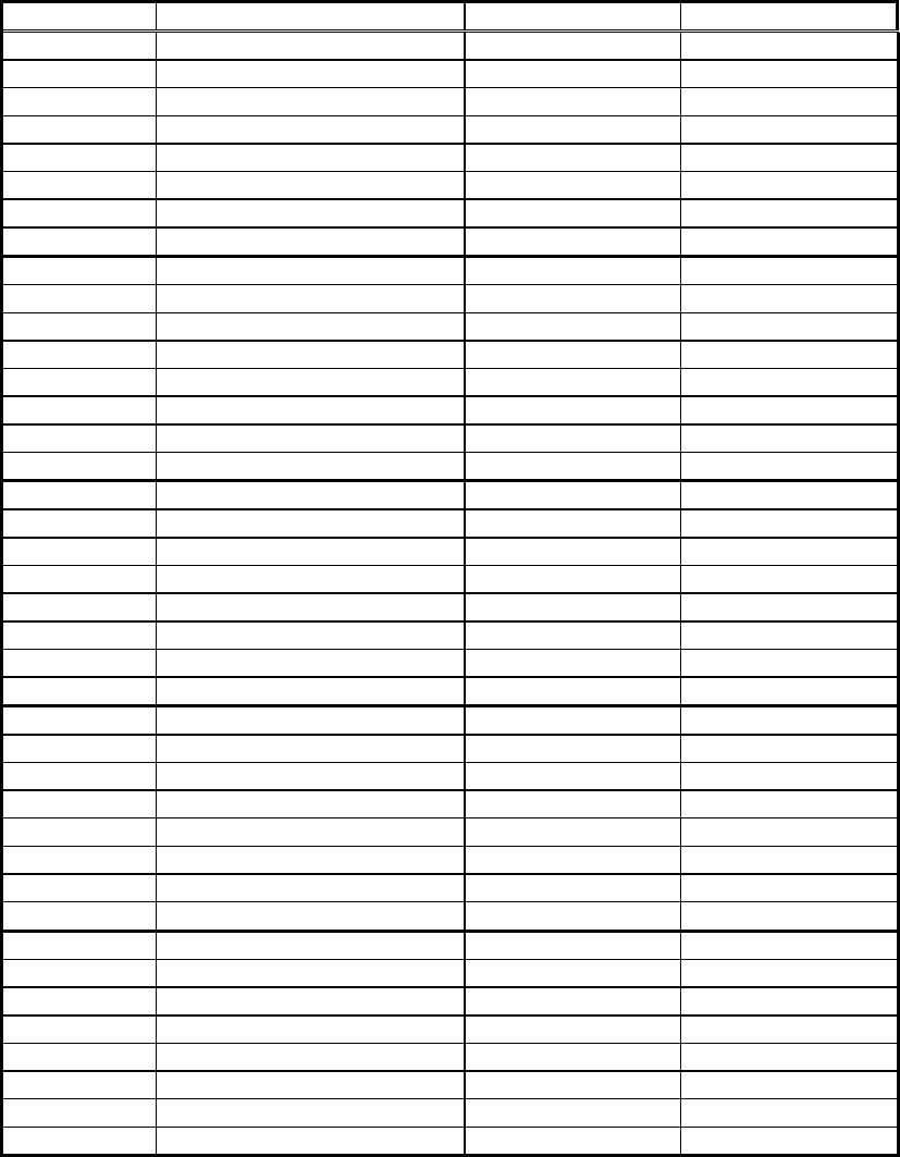
- 267 -
4.1.3 CT-S2000
No. Setting OFF ON
MSW1-1 Power ON Info ● Valid Not send
MSW1-2 Buffer Size ● 4K bytes 45 bytes
MSW1-3 Busy Condition ● Full/Err Full
MSW1-4 Receive Error ● Print ? No Print
MSW1-5 CR mode ● Ignored LF
MSW1-6 Reserved ● Fixed ―
MSW1-7 DSR Signal ● Invalid Valid
MSW1-8 Init Signal ● Invalid Valid
MSW2-1 Reserved ― ● Fixed
MSW2-2 Auto Cutter Invalid ● Valid
MSW2-3 Spool Print ● Invalid Valid
MSW2-4 Full Col Print ● LineFeed WaitData
MSW2-5 Resume aft PE ● Next Top
MSW2-6 Reserved ● Fixed ―
MSW2-7 Reserved ● Fixed ―
MSW2-8 PNE Sensor ● Valid Invalid
MSW3-1 Resum Cttr Err ● Valid Invalid
MSW3-2 Reserved ● Fixed ―
MSW3-3 Parallel 31 Pin ● Valid Invalid
MSW3-4 Reserved ● Fixed ―
MSW3-5 Reserved ● Fixed ―
MSW3-6 Reserved ● Fixed ―
MSW3-7 CBM1000 Mode Invalid ● Valid
MSW3-8 Resum Open Err ● Close Command
MSW4-1 BM Measure ● Invalid Valid
MSW4-2 Reserved ● Fixed ―
MSW4-3 Feed&Cut at TOF Invalid ● Valid
MSW4-4 Reserved ● Fixed ―
MSW4-5 Reserved ● Fixed ―
MSW4-6 Reserved ● Fixed ―
MSW4-7 Reserved ● Fixed ―
MSW4-8 Partial only Invalid ● Valid
MSW5-1 Buzzer ● Valid Invalid
MSW5-2 Line Pitch ● 360 406
MSW5-3 USB Mode Virtual COM ● Printer Class
MSW5-4 Reserved ● Fixed ―
MSW5-5 No use ● Fixed ―
MSW5-6 No use ● Fixed ―
MSW5-7 No use ● Fixed ―
MSW5-8 No use ● Fixed ―
●: Factory setting

- 268 -
No. Setting Default Set Values
MSW7-1 Baud Rate 19200bps 2400bps,4800bps,9600bps,19200bps,38400bps,
57600bps,115200bps
MSW7-2 Data Length 8bits 7bits,8bits
MSW7-3 Stop Bit 1bit 1bit,2bits
MSW7-4 Parity None None, Odd, Even
MSW7-5 Flow Control DTR/DSR DTR/DSR, Xon/Xoff
MSW7-6 DMA control Valid Valid, Invalid
MSW7-7 VCom Protocol PC setting PC setting, DTR/DSR, XON/XOFF
MSW8-1 Print Width 576dots 640dots,576dots,512dots,436dots,432dots,
420dots,384dots,360dots
MSW8-2 Paper Type 1 Color
Normal
1 Color Normal, 1 Color B.M, 1 Color Label,
2 Color Normal, 2 Color B.M
MSW9-1 Code Page PC437
PC437,Katakana,PC850,PC858,PC860,PC863,
PC865,PC852,PC866,PC857,WindowsCode,
PC864,ThaiCode18
MSW9-2 Int’Char Set America
America, France, Germany, England, Denmark,
Sweden, Italy, Spain, Japan, Norway, Denmark 2,
Spain 2, Latin America, Korea
MSW9-3 Kanji OFF ON, OFF
MSW9-4 JIS/Shift JIS JIS JIS, Shift JIS
MSW10-1 Print Density 100% 70%,75%,80%,85%,90%,95%,100%,105%,
110%,115%,120%,125%,130%,135%,140%
MSW10-2 Print Speed Level9 Level1,Level2,Level3,evel4,Level5,Level6,
Level7,Level8,Level9
MSW10-3 ACK Timing Before
BUSY Before Busy, Same Period, After Busy

- 269 -
4.1.4 CT-S4000
No. Setting OFF ON
MSW1-1 Power ON Info ● Valid Not send
MSW1-2 Buffer Size ● 4K bytes 45 bytes
MSW1-3 Busy Condition ● Full/Err Full
MSW1-4 Receive Error ● Print “?” No Print
MSW1-5 CR mode ● Ignored LF
MSW1-6 Reserved ● Fixed ―
MSW1-7 DSR Signal ● Invalid Valid
MSW1-8 Init Signal ● Invalid Valid
MSW2-1 Reserved ― ● Fixed
MSW2-2 Auto Cutter Invalid ● Valid
MSW2-3 Spool Print ● Invalid Valid
MSW2-4 Full Col Print ● LineFeed WaitData
MSW2-5 Resume aft PE ● Next Top
MSW2-6 Reserved ● Fixed ―
MSW2-7 Reserved ● Fixed ―
MSW2-8 PNE Sensor ● Valid Invalid
MSW3-1 Resum Cttr Err ● Valid Invalid
MSW3-2 Reserved ● Fixed ―
MSW3-3 Parallel 31 Pin ● Valid Invalid
MSW3-4 Reserved ● Fixed ―
MSW3-5 Reserved ● Fixed ―
MSW3-6 Reserved ● Fixed ―
MSW3-7 CBM1000 Mode ● Invalid Valid
MSW3-8 Resum Open Err ● Close Command
MSW4-1 P.Length Set Auto Measure Command
MSW4-2 Power on TOF ● Invalid Valid
MSW4-3 FEED&CUT at TOF Invalid ● Valid
MSW4-4 Paper Select(*1) Thermal Roll BM.P/Lbl.P
MSW4-5(*3) Position Detect(*2) Black Mark Label
MSW4-6 Reserved ● Fixed ―
MSW4-7 Reserved ● Fixed ―
MSW4-8 Partial only Invalid ● Valid
MSW5-1 Buzzer Valid ● Invalid
MSW5-2 Line Pitch ● 1/360 1/406
MSW5-3 USB Mode Virtual COM ● Printer Class
MSW5-4 Reserved ● Fixed ―
MSW5-5 Power OFF Info ● Invalid Valid
MSW5-6 Reserved ● Fixed ―
MSW5-7 Reserved ● Fixed ―
MSW5-8 Reserved ● Fixed ―
●: Factory setting
*1)Default for paper selection depends on the model selected.
*2)Invalid when thermal rolled paper is selected by MSW4-4.
Black mark option product is fixed at black mark detection.
*3)Valid only with black mark or label-support model.
Black mark is optional.

- 270 -
No. Setting Default Set Values
MSW7-1 Baud Rate 19200bps 1200bps,2400bps,4800bps,9600bps,19200bps,
38400bps,57600bps,115200bps
MSW7-2 Data Length 8bits 7bits,8bits
MSW7-3 Stop Bit 1bit 1bit,2bits
MSW7-4 Parity None None, Odd, Even
MSW7-5 Flow Control DTR/DSR DTR/DSR, Xon/Xoff
MSW7-6 DMA control Valid Valid, Invalid
MSW7-7 VCom Protocol PC setting PC setting, DTR/DSR, XON/XOFF
MSW8-1 Print Width 832dots 832dots,720dots,660dots,576dots,512dots
MSW8-2 Paper Type 1 Color 1 Color , 2 Color
MSW9-1 Code Page PC437
PC437,Katakana,PC850,PC858,PC860,PC863,
PC865,PC852,PC866,PC857,WindowsCode,
PC864,ThaiCode18
MSW9-2 Int’Char Set America
America, France, Germany, England, Denmark,
Sweden, Italy, Spain, Japan, Norway, Denmark 2,
Spain 2, Latin America, Korea
MSW9-3 Kanji OFF ON, OFF
MSW9-4 JIS/Shift JIS JIS JIS, Shift JIS
MSW10-1 Print Density 100% 70%,75%,80%,85%,90%,95%,100%,105%,
110%,115%,120%,125%,130%,135%,140%
MSW10-2 Print Speed Level9 Level1,Level2,Level3,evel4,Level5,Level6,
Level7,Level8,Level9
MSW10-3 ACK Timing Before
BUSY Before Busy, Same Period, After Busy
MSW10-4 NV User 192Kbytes 1Kbytes,64Kbytes,128Kbytes,192Kbytes
MSW10-5 NV Graphic 384Kbytes 0byte,64Kbytes,128Kbytes,192Kbytes,256Kbytes,
320Kbytes,384Kbytes

- 271 -
4.1.5 BD2-2220
No. Setting OFF ON
MSW1-1 Power ON Info ● Valid Not send
MSW1-2 Buffer Size ● 4K bytes 45 bytes
MSW1-3 Busy Condition ● Full/Err Full
MSW1-4 Receive Error ● Print ? No Print
MSW1-5 CR mode ● Ignored LF
MSW1-6 Reserved ● Fixed ―
MSW1-7 DSR Signal ● Invalid Valid
MSW1-8 Reserved ● Fixed ―
MSW2-1 Reserved ― ● Fixed
MSW2-2 Reserved ― ● Fixed
MSW2-3 Spool Print ● Invalid Valid
MSW2-4 Full Col Print ● LineFeed WaitData
MSW2-5 Resume aft H.D(*) ● Next Top
MSW2-6 Reserved ― ● Fixed
MSW2-7 Reserved ● Fixed ―
MSW2-8 Reserved ● Fixed ―
MSW3-1 Resum Cttr Err ● Valid Invalid
MSW3-2 Reserved ● Fixed ―
MSW3-3 Reset ● Valid Invalid
MSW3-4 Reserved ● Fixed ―
MSW3-5 Reserved ● Fixed ―
MSW3-6 Reserved ● Fixed ―
MSW3-7 Reserved ● Fixed ―
MSW3-8 Resum H.U Err(*) Close ● Command
●: Factory setting
*This function is enabled for platen close/open operation when LT-2x21 is used.

- 272 -
4.1.6 CT-S310
No. Setting OFF ON
MSW1-1 Power ON Info ● Valid Not send
MSW1-2 Buffer Size ● 4K bytes 45 bytes
MSW1-3 Busy Condition ● Full/Err Full
MSW1-4 Receive Error ● Print “?” No Print
MSW1-5 CR mode ● Ignored LF
MSW1-6 Reserved ● Fixed ―
MSW1-7 DSR Signal ● Invalid Valid
MSW1-8 Init Signal ● Invalid Valid
MSW2-1 Reserved ― ● Fixed
MSW2-2 Auto Cutter Invalid ● Valid
MSW2-3 Spool Print ● Invalid Valid
MSW2-4 Full Col Print LineFeed ● WaitData
MSW2-5 Resume aft PE ● Next Top
MSW2-6 Paper Width ● 80mm 58mm
MSW2-7 Reserved ● Fixed ―
MSW2-8 PNE Sensor ● Valid Invalid
MSW3-1 Resum Cttr Err ● Valid Invalid
MSW3-2 Reserved ● Fixed ―
MSW3-3 Parallel 31 Pin ● Valid Invalid
MSW3-4 Paper Select ● Thermal Black MK
MSW3-5 Column Number ● 48/32Col 42/30Col
MSW3-6 Reserved ● Fixed ―
MSW3-7 CBM1000 Mode ● Invalid Valid
MSW3-8 Resum Open Err ● Close Command
MSW4-1 Auto Length ● Invalid Auto
MSW4-2 BM sensor ● Surface Back
MSW4-3 FEED&CUT at TOF Invalid ● Valid
MSW4-4 Reserved ● Fixed ―
MSW4-5 Reserved ● Fixed ―
MSW4-6 Reserved ● Fixed ―
MSW4-7 Reserved ● Fixed ―
MSW4-8 Partial only Invalid ● Valid
MSW5-1 Buzzer ● Auto Invalid
MSW5-2 Reserved ● Fixed ―
MSW5-3 USB Mode Virtual COM ● Printer Class
MSW5-4 Reserved ● Fixed ―
MSW5-5 Power OFF Info ● Valid Invalid
MSW5-6 Reserved ● Fixed ―
MSW5-7 Clear PNE LED ● Auto Paper set
MSW5-8 Reserved ● Fixed ―
●: Factory setting
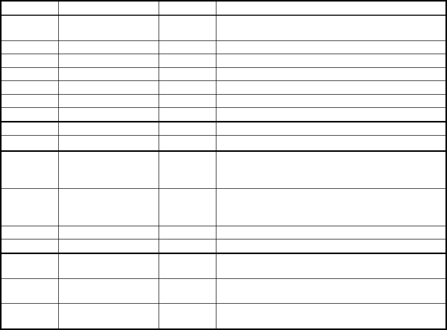
- 273 -
No. Setting Default Set Values
MSW7-1 Baud Rate 19200bps 1200bps,2400bps,4800bps,9600bps,19200bps,
38400bps
MSW7-2 Data Length 8bits 7bits,8bits
MSW7-3 Stop Bit 1bit 1bit,2bits
MSW7-4 Parity None None, Odd, Even
MSW7-5 Flow Control Xon/Xoff DTR/DSR, Xon/Xoff
MSW7-6 Reserved ― ―
MSW7-7 VCom Protocol PC setting PC setting, DTR/DSR, XON/XOFF
MSW8-1 Reserved ― ―
MSW8-2 Paper Type 1 Color 1 Color , 2 Color
MSW9-1 Code Page PC437
PC437,Katakana,PC850,PC858,PC860,PC863,
PC865,PC852,PC866,PC857,WindowsCode,
PC864,ThaiCode18
MSW9-2 Int’Char Set USA
USA, France, Germany, England, Denmark, Sweden,
Italy, Spain, Japan, Norway, Denmark 2, Spain 2,
Latin America, Korea
MSW9-3 Kanji OFF ON, OFF
MSW9-4 JIS/Shift JIS JIS JIS, Shift JIS
MSW10-1 Print Density 100% 70%,75%,80%,85%,90%,95%,100%,105%,
110%,115%,120%,125%,130%,135%,140%
MSW10-2 Print Speed Level9 Level1,Level2,Level3,evel4,Level5,Level6,
Level7,Level8,Level9
MSW10-3 ACK Timing Before
BUSY Before Busy, Same Period, After Busy

- 274 -
4.1.7 PMU2XXX
No. Setting OFF ON
MSW1-1 Power ON Info ● Valid Not send
MSW1-2 Buffer Size ● 4K bytes 45 bytes
MSW1-3 Busy Condition ● Full/Err Full
MSW1-4 Receive Error ● Print “?” No Print
MSW1-5 CR mode ● Ignored LF
MSW1-6 Reserved ● Fixed ―
MSW1-7 DSR Signal ● Invalid Valid
MSW1-8 Reserved ● Fixed ―
MSW2-1 Reserved ― ● Fixed
MSW2-2 Auto Cutter Invalid ● Valid
MSW2-3 Spool Print ● Invalid Valid
MSW2-4 Full Col Print ● LineFeed ● WaitData
MSW2-5 Resume aft PE ● Print next line Print top line
MSW2-6 Paper Width ● 80mm 58mm
MSW2-7 Reserved ● Fixed ―
MSW2-8 PNE Sensor Valid ● Invalid
MSW3-1 Resum Cttr Err ● Valid Invalid
MSW3-2 Reserved ● Fixed ―
MSW3-3 Parallel 31 Pin ● Valid Invalid
MSW3-4 Paper Select ● Thermal Black MK
MSW3-5 Reserved ● Fixed ―
MSW3-6 Reserved ● Fixed ―
MSW3-7 Reserved ● Fixed ―
MSW3-8 Resum Open Err ● Close Command
MSW4-1 Auto Length ● Invalid Auto
MSW4-2 BM sensor ● Surface Back
MSW4-3 FEED&CUT at TOF Invalid ● Valid
MSW4-4 Base style ●PMU2xx0/2 PMU2xx1
MSW4-5 Mechanism mounted ●LT-23xx LT-22xx
MSW4-6 Reserved ● Fixed ―
MSW4-7 Reserved ● Fixed ―
MSW4-8 Partial only ● Invalid Valid
MSW5-1 Reserved ● Fixed ―
MSW5-2 Reserved ● Fixed ―
MSW5-3 Reserved ● Fixed ―
MSW5-4 Reserved ● Fixed ―
MSW5-5 Reserved ● Fixed ―
MSW5-6 Speed / Quality Quality ● Speed
MSW5-7 Reserved ● Fixed ―
MSW5-8 Reserved ● Fixed ―
●: Factory setting
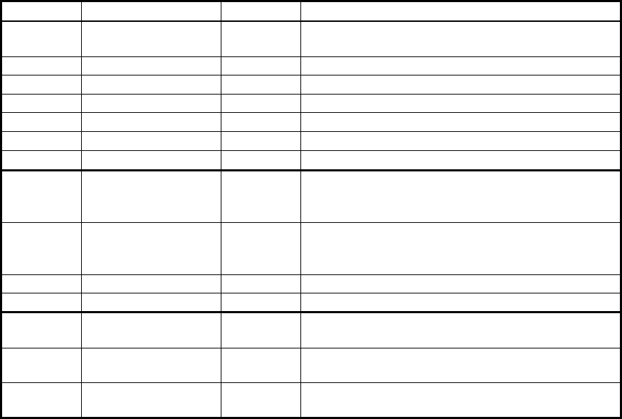
- 275 -
No. Setting Default Set Values
MSW7-1 Baud Rate 9600bps 1200bps,2400bps,4800bps,9600bps,19200bps,
38400bps,57600bps,115200bps
MSW7-2 Data Length 8bits 7bits,8bits
MSW7-3 Stop Bit 1bit 1bit,2bits
MSW7-4 Parity None None, Odd, Even
MSW7-5 Flow Control DTR/DSR DTR/DSR, Xon/Xoff
MSW7-6 Reserved - -
MSW7-7 Reserved - -
MSW9-1 Code Page PC437
PC437,Katakana,PC850,PC858,PC860,PC863,
PC865,PC852,PC866,PC857,WindowsCode,
PC864,ThaiCode18
MSW9-2 Int’Char Set USA
USA, France, Germany, England, Denmark, Sweden,
Italy, Spain, Japan, Norway, Denmark 2, Spain 2,
Latin America, Korea, Croatia, China
MSW9-3 Kanji OFF ON, OFF
MSW9-4 JIS/Shift JIS JIS JIS, Shift JIS
MSW10-1 Print Density 100% 70%,75%,80%,85%,90%,95%,100%,105%,
110%,115%,120%,125%,130%,135%,140%
MSW10-2 Print Speed Level9 Level1,Level2,Level3,evel4,Level5,Level6,
Level7,Level8,Level9
MSW10-3 ACK Timing Before
BUSY Before Busy, Same Period, After Busy
- 276 -
4.2 Details of Memory Switches
This section describes the function of memory switch.
Some MSW may not be set or some values may not be selected depending on the model used. For the
MSW and value that can be set or selected with the model you are using, refer to the operation manual
or the like.
4.2.1 MSW1
●MSW1-1: Setting the power ON notify
[Outline] At power ON, to notify the host of the printer power ON, printer can send to host 3 byte power ON
notify’s status data (<3B>H <31>H <00>H).
Set to enable/disable for sending the power ON notify’s status data.
OFF(0) ON(1)
Power ON Info Valid Not send
ON (1) OPERATION:
Function to notify power ON is disabled, sending no status to host.
OFF (0) OPERATION:
Function to notify power ON is enabled, sending status to host.
●MSW1-2: Input buffer
[Outline] Select the input buffer (receive buffer) size.
OFF(0) ON(1)
Buffer Size 4Kbytes 45bytes
ON (1) OPERATION: Input buffer size is set to 45 bytes.
From when free area decreases to 16 bytes until it increases to 26 bytes, receive buffer is full with
printer BUSY status.
OFF (0) OPERATION: Input buffer size is set to 4K bytes.
From when free area decreases to 128 bytes until it increases to 256 bytes, receive buffer is full
with printer BUSY status.
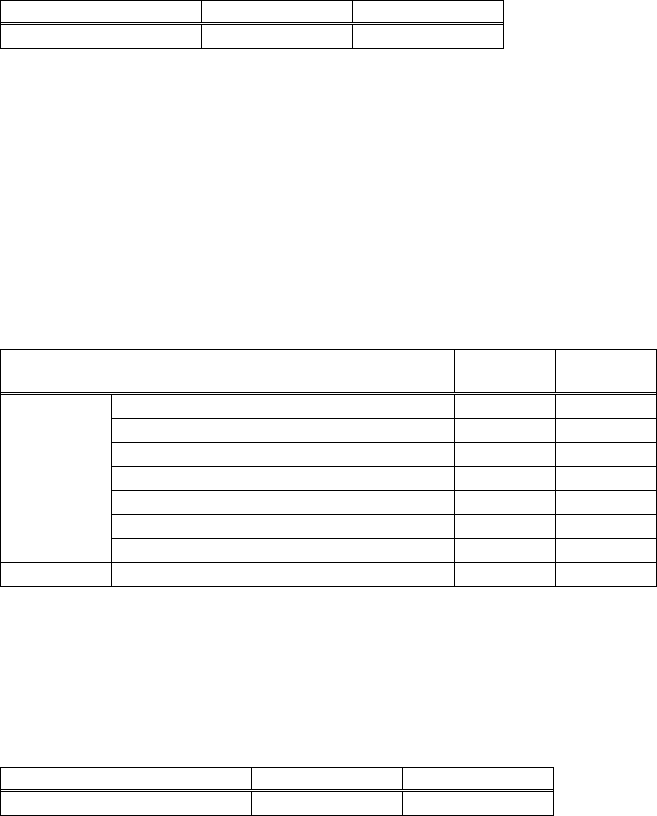
- 277 -
●MSW1-3: Busy condition
[Outline] Select the condition that printer is BUSY. Automatic status send function also runs.
OFF(0) ON(1)
Busy Condition Buffer full/Off-line Buffer full
ON (1) OPERATION: If receive buffer is full, printer is BUSY.
Automatic status send (ASB) function is enabled.
OFF (0) OPERATION: If receive buffer is full or off-line, printer is BUSY.
Automatic status send (ASB) function is disabled.
[Additional Description]
Even if ON is selected, printer enters BUSY status when power is turned on or reset by I/F or at self
test print
Printer Status MSW1-3
OFF
MSW1-3
ON
Power-up or reset used by I/F ● ●
Self-print ● ●
Cover open ● ―
Paper-feed by FEED SW ● ―
Paper-end (including print stop in PNE) ● ―
Error generation ● ―
Off-line
Waiting during macro run by FEED SW ● ―
Buffer full Receive buffer full ● ●
●MSW1-4: Receive error character
[Outline] Select handling of data detected where the serial communication detects the receive data framing
error, overrun error and parity error.
OFF(0) ON(1)
Receive Error Print ? No Print
ON (1) OPERATION: Not printed as “?”
OFF (0) OPERATION: Printed as “?”
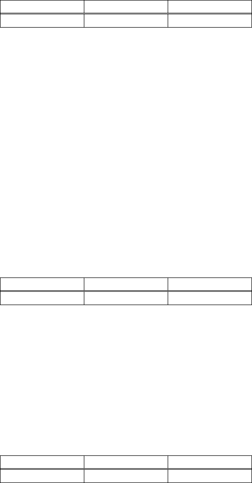
- 278 -
●MSW1-5: CR code
[Outline] Select the printer when receiving CR(<0D>H) code.
OFF(0) ON(1)
CR mode Ignored LF
ON (1) OPERATION:
Select the same operation with LF when receiving CR code.
Print data in print buffer and put linefeeds as specified.
OFF (0) OPERATION:
CR code may be ignored with no actions if receiving CR code.
●MSW1-6: Reserved [Fixed to OFF (0)]
●MSW1-7: DSR signal
[Outline] Printer can be reset with DSR (serial I/F-6pin) signal. Select enable/disable of reset function with
this signal.
OFF(0) ON(1)
DSR Signal Invalid Valid
ON (1) OPERATION: Used as reset signal
OFF (0) OPERATION: Not used as reset signal
●MSW1-8: INIT signal
[Outline] Printer can be reset with INIT (serial I/F-25Pin) signal. Select enable/disable of reset function with
this signal.
OFF(0) ON(1)
INIT Signal Invalid Valid
ON (1) OPERATION: Used as reset signal
OFF (0) OPERATION: Not used as reset signal
- 279 -
4.2.2 MSW2
●MSW2-1: Reserved [Fixed to ON(1)]
●MSW2-2: Auto-cutter operation
[Outline] Select auto-cutter enable/disable.
OFF(0) ON(1)
Auto Cutter Invalid Valid
ON (1) OPERATION: Auto-cutter enabled
OFF (0) OPERATION: Auto-cutter disabled
●MSW2-3: Buffering
[Outline] Select buffering print enable/disable.
OFF(0) ON(1)
Spool Print Invalid Valid
ON (1) OPERATION: Buffering print is enabled. Buffering print means that save a certain amount of
print buffer to internal RAM for collective printing
・ Save a certain amount of print buffer to internal RAM for collective printing.
・ If cut command such as GS+V ESC+i ESC +m are entered, print starts even
before the specified amount is reached. FF or GS+FF command In Black
mark mode or label model works same way.
・ Even if no cut command is entered and the entered data does not reach
the specified amount, entered data to print buffer is printed after no new
deta comes to print buffer for certain period.
OFF (0) OPERATION: Buffering print is disabled.
- 280 -
●MSW2-4: Full Columns print
[Outline] Select the processing if print data closes to the end of line or the right of print width.
OFF(0) ON(1)
Full Col print Line Feed Wait Data
ON (1) OPERATION:
If printer receives data/command exceeding the full column, printer further waits for print data.
If data exceeding the full column is a command, printer operates following the command.
OFF (0) OPERATION:
If printer receives data/command exceeding the full column, it automatically prints data in buffer
followed by a line-feed.
<Example>
If the first data after exceeding the full column is a control code such as<ESC !>;
If OFF (0) is set, print data within buffer and put a line feed, or
If ON (1) is set, print no data within buffer and further wait for print data.
●MSW2-5: Cover close return
[Outline] Select the operating taken after printer cover is opened during printing, paper is refilled with
no-paper (PE) is detected, then cover is closed to restart printing.
OFF(0) ON(1)
Resume aft PE Next Top
ON (1) OPERATION:
Restart printing from the heading of remaining data.
During printing image, bar code, vertically-doubled character or page mode, if cover open or PE is
detected, then after return, restart printing from heading of the remaining data.
OFF (0) OPERATION:
Print data continued from the previous printing. During printing, if cover open or PE is detected,
then after return, restart printing data immediately after an error data.
*With BD2-2220, Cover Close corresponds to Head Down (Platen Close) and Cover Open
to Head Up (Platen Open).
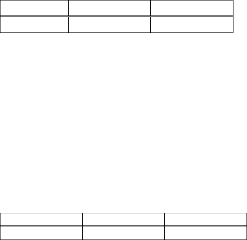
- 281 -
●MSW2-6: Paper width
[Outline] Select paper width.
OFF(0) ON(1)
Paper width 80mm 58mm
ON (1) OPERATION: Paper width is set 80mm
OFF (0) OPERATION: Paper width is set 58mm
●MSW2-7: Reserved [Fixed to OFF (0)]
●MSW2-8: PNE sensor
[Outline] Select paper near-end enable/disable.
OFF(0) ON(1)
PNE Sensor Valid Invalid
ON (1) OPERATION: Disable paper near-end
OFF (0) OPERATION: Enable paper near-end
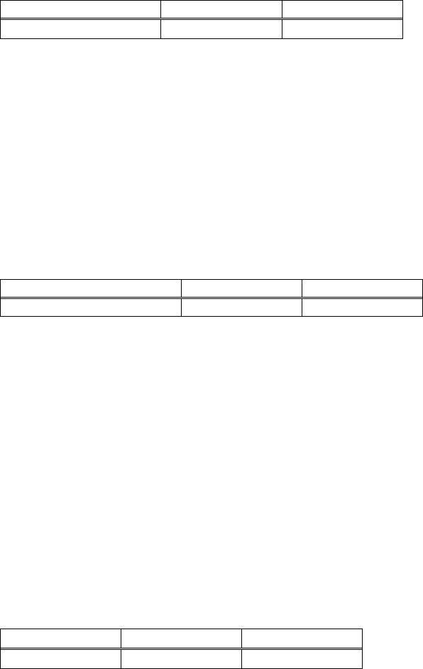
- 282 -
4.2.3 MSW3
●MSW3-1: Auto-cutter return
[Outline] Select return method from cutter lock error.
OFF(0) ON(1)
Resum Cttr Err Valid Invalid
ON (1) OPERATION: Return by command.
After removing error cause, return with command <DLE ENQ n>.
OFF (0) OPERATION: Return with FEED switch.
After removing error cause, return by long pressing FEED SW (1 sec or longer).
●MSW3-2: Clearing Cover Open Error
[Outline] Selects the method of clearing Cover Open error.
OFF(0) ON(1)
Resum Open Err Close Command
Operation at ON (1):
When the printer detects that cover is closed and the printer receives a command
<DLE+ENQ+n>, the error is cleared.
Operation at OFF (0):
When the printer detects that the cover is closed, it automatically clears the error.
*With BD2-2220, Cover Open corresponds to Head Up (Platen Open).
●MSW3-3: Parallel 31 pin
[Outline] Printer can be reset by parallel I/F –31 Pin signal. Select the handling of this signal.
OFF(0) ON(1)
Parallel 31 pin Valid Invalid
ON (1) OPERATION: Used as reset signal
OFF (0) OPERATION: Not used as reset signal
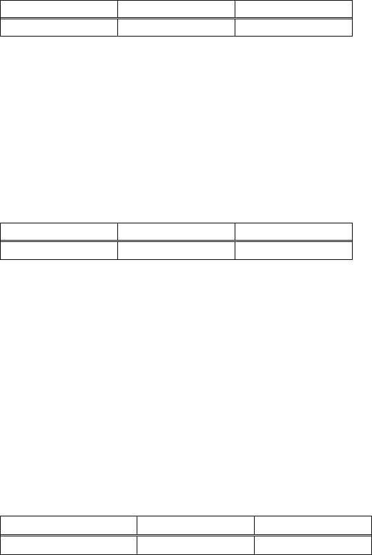
- 283 -
●MSW3-4: Selecting paper
[Outline] Selects either thermal paper or black mark paper.
OFF(0) ON(1)
Paper Select Thermal Black Mark
Operation at ON (1): Sets black mark paper.
Operation at OFF (0): Sets thermal paper.
●MSW3-5: Column Number
[Outline] Selects column number.
OFF(0) ON(1)
Column Number 48/32 col 42/30 col
Operation at ON (1): Column number is set 42/30 columns
Operation at OFF (0): Column number is set 48/32 columns
●MSW3-6: Reserved [Fixed to OFF (0)]
●MSW3-7: CBM compatible mode
[Outline] Select enable/disable of CBM compatible mode.
OFF(0) ON(1)
CBM Mode Invalid Valid
ON (1) OPERATION: Enable CBM compatible mode.
Control code <ESC ~ J> becomes available.
OFF (0) OPERATION: CBM compatible mode is disabled.

- 284 -
●MSW3-8: Cover open during printing
[Outline] Select the release method of cover open error during printing.
OFF(0) ON(1)
Resum Open Err Close Command
ON (1) OPERATION: Cover open error during printing becomes a return allowed error.
Returned with command <DLE ENQ n> after cover is closed.
OFF (0) OPERATION: Cover open error during printing becomes an automatic return error.
Automatically returned from cover open error by closing the cover.
*With BD2-2220, Cover Close corresponds to Head Down (Platen Close) and Cover Open
to Head Up (Platen Open).
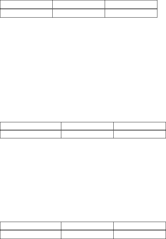
- 285 -
4.2.4 MSW4
●MSW4-1: Automatic length measurement
[Outline] In selecting black mark paper, set the enable/disable of automatic length measurement.
(Black mark/label support model only)
OFF(0) ON(1)
BM Measure Invalid Valid
ON (1) OPERATION: Automatic length measurement is enabled.
At power-up, measurement operation is taken.
OFF (0) OPERATION: Automatic length measurement is disabled.
Operation follows the value set by <GS l>.
●MSW4-2: Black mark sensor position
[Outline] Selects black mark sensor position.
OFF(0 ON(1
BM sensor position surface back
ON (1) OPERATION: Black mark sensor detects a black mark on the printing surface.
OFF (0) OPERATION: Black mark sensor detects a black mark on the printing back.
●MSW4-3: Paper heading cut
[Outline] When cover is closed, feed paper before cut.
OFF(0) ON(1)
Feed & Cut at TOF Invalid Valid
ON (1) OPERATION: Paper heading cut is enabled.
OFF (0) OPERATION: Paper heading cut is disabled.
- 286 -
●MSW4-4: Paper
[Outline] Selects the type of paper used.
OFF(0) ON(1)
Paper Thermal roll paper Black mark paper/Label paper
ON (1) OPERATION: Paper used is limited to black mark paper or label paper.
OFF (0) OPERATION: Paper used is limited to thermal roll paper.
●MSW4-5: Position detect
[Outline] Selects the method of detecting paper position.
OFF(0) ON(1)
Position detect Black mark Label
ON (1) OPERATION: Detects paper position by detecting the inter-label distance.
OFF (0) OPERATION: Detects the paper position by detecting the black mark.
*This function is valid only with black mark specification or label specification.
*If thermal roll paper is selected by MSW4-4, this function is invalid.
*Black mark detection is fixed with black mark specification.
●MSW4-6: Reserved [Fixed to OFF (0)]
●MSW4-7: Reserved [Fixed to OFF (0)]
●MSW4-8: Forcible partial cut
[Outline] Select the operation taken when full cut command is received.
OFF(0) ON(1)
Partial only Invalid Valid
ON (1) OPERATION: When full cut command is received, partial cut, not full cut, is taken.
OFF (0) OPERATION: When full cut command is received, full cut is taken.
- 287 -
4.2.5 MSW5
●MSW5-1: Buzzer
[Outline] Select the enable/disable of buzzer.
OFF(0) ON(1)
Buzzer Valid Invalid
ON (1) OPERATION: Disable buzzer
When an error occurs or memory switch setting is changed manually, no buzzer sounds.
OFF (0) OPERATION: Enable buzzer.
When an error occurs or memory switch setting is changed manually, the buzzer sounds.
●MSW5-2: Basic vertical calculation pitch
[Outline] Select the basic calculation pitch in the paper feed direction.
OFF(0) ON(1)
Line Pitch 360 406
ON (1) OPERATION: Basic vertical calculation pitch is set to 1/406 inch.
Line-feed length is 3.75mm by default.
OFF (0) OPERATION: Basic vertical calculation pitch is set to 1/360 inch.
Line-feed length is 4.23mm by default.
●MSW5-3: USB mode
[Outline] Select USB mode.
OFF(0) ON(1)
USB Mode Virtual COM Printer Class
ON (1) OPERATION: Operated as Printer class
OFF (0) OPERATION: Operated as virtual COM class
●MSW5-4: Reserved [Fixed to OFF (0)]
- 288 -
●MSW5-5: Setting the power OFF notify
[Outline] At power OFF, to notify the host of the printer power OFF, printer can send to host 3 byte power
OFF notify’s status data (<3B>H <31>H <00>H).
Set to enable/disable for sending the power OFF notify’s status data.
OFF(0) ON(1)
Power OFF Info Not send Valid
ON (1) OPERATION:
Function to notify power ON is enabled, sending status to host.
OFF (0) OPERATION:
Function to notify power ON is disabled, sending no status to host.
●MSW5-6: Not defined [Fixed to OFF (0)]
●MSW5-7: Not defined [Fixed to OFF (0)]
●MSW5-8: Not defined [Fixed to OFF (0)]
4.2.6 MSW6
No selectable function
- 289 -
4.2.7 MSW7
●MSW7-1: Baud rate
[Outline] Select baud rate which is serial interface communication condition.
Enabled if DSW1-1 OFF is set [following memory switch setting].
Setting Value
Baud Rate 1200bps,2400bps,4800bps,9600bps,19200bps,
38400bps,57600bps,115200bps
●MSW7-2: Data length
[Outline] Select the data length, which is a serial interface communication condition.
Enabled if DSW1-1 OFF is set [following memory switch setting].
Setting Value
Data Length 7bits,8bits
●MSW7-3: Stop bit
[Outline] Select the stop bit, which is a serial interface communication condition.
Enabled if DSW1-1 OFF is set [following memory switch setting].
Setting Value
Stop Bit 1bit,2bits
●MSW7-4: Parity
[Outline] Select the parity, which is a serial interface communication condition.
Enabled if DSW1-1 OFF is set [following memory switch setting].
Setting Value
Parity NONE, ODD, EVEN
●MSW7-5: Busy control
[Outline] Select the busy control, which is a serial interface communication condition.
Enabled if DSW1-1 OFF is set [following memory switch setting].
Setting Value
Flow Control DTR/DSR, XON/XOFF
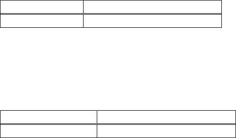
- 290 -
●MSW7-6: DMA control
[Outline] Select the enable/disable of DMA (Direct Memory Access) control.
Setting Value
DMA control Valid, Invalid
●MSW7-7: VCom flow control
[Outline] In MSW5-3, select the flow control when virtual COM is set.
Setting Value
VCom Protocal PC setting, DTR/DSR, XON/XOFF

- 291 -
4.2.8 MSW8
●MSW8-1: Print width
[Outline] Select the print width in dots.
Setting Value
Print Width 832dots,720dots,660dots,640dots,576dots,512dots,
436dots,432dots,420dots,384dots,360dots
●MSW8-2: Paper type
[Outline] Select the paper type used.
Setting Value
Paper Type 1 Color Normal, 1 Color BM, 1 Color Label,
2 color Normal, 2 Color BM
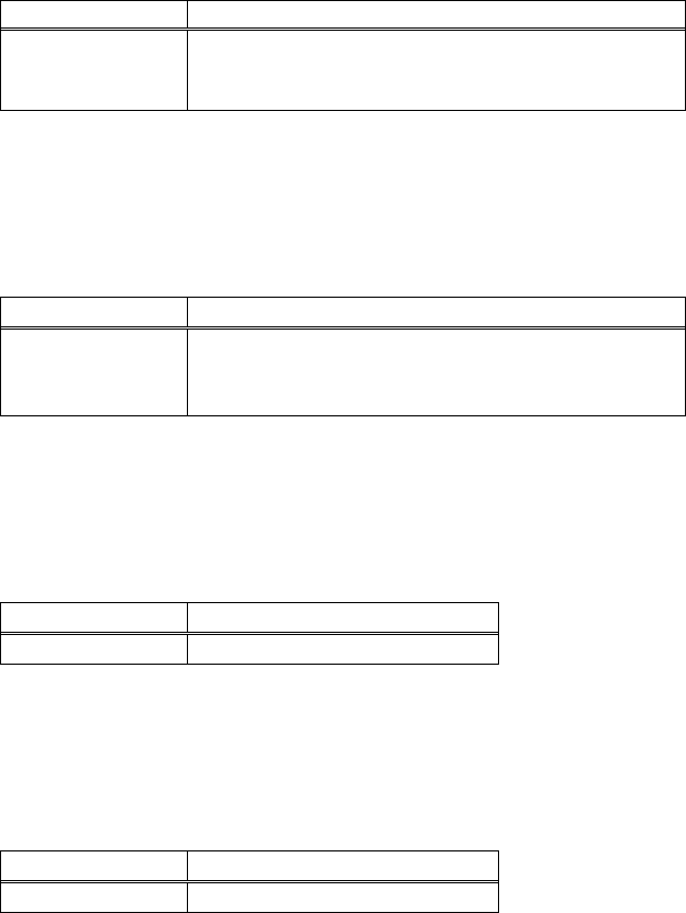
- 292 -
4.2.9 MSW9
●MSW9-1: Code page
[Outline] Select the code page.
Setting Value
Code Page
PC437,Katakana,PC850,PC858,PC860,PC863,
PC865,PC852,PC866,PC857,WindowsCode,
PC864,ThaiCode18
●MSW9-2: International character
[Outline] Select the international character.
Setting Value
Int’Char Set
USA, France, Germany, UK, Denmark, Sweden, Italy,
Spain, Japan, Norway, Denmark 2, Spain2, Latin
America, Korea
●MSW9-3: Kanji
[Outline] Select the enable/disable of Kanji.
Setting Value
Kanji ON, OFF
●MSW9-4: JIS
[Outline] Select the kanji code system.
Setting Value
JIS/Shift JIS JIS, Shift JIS
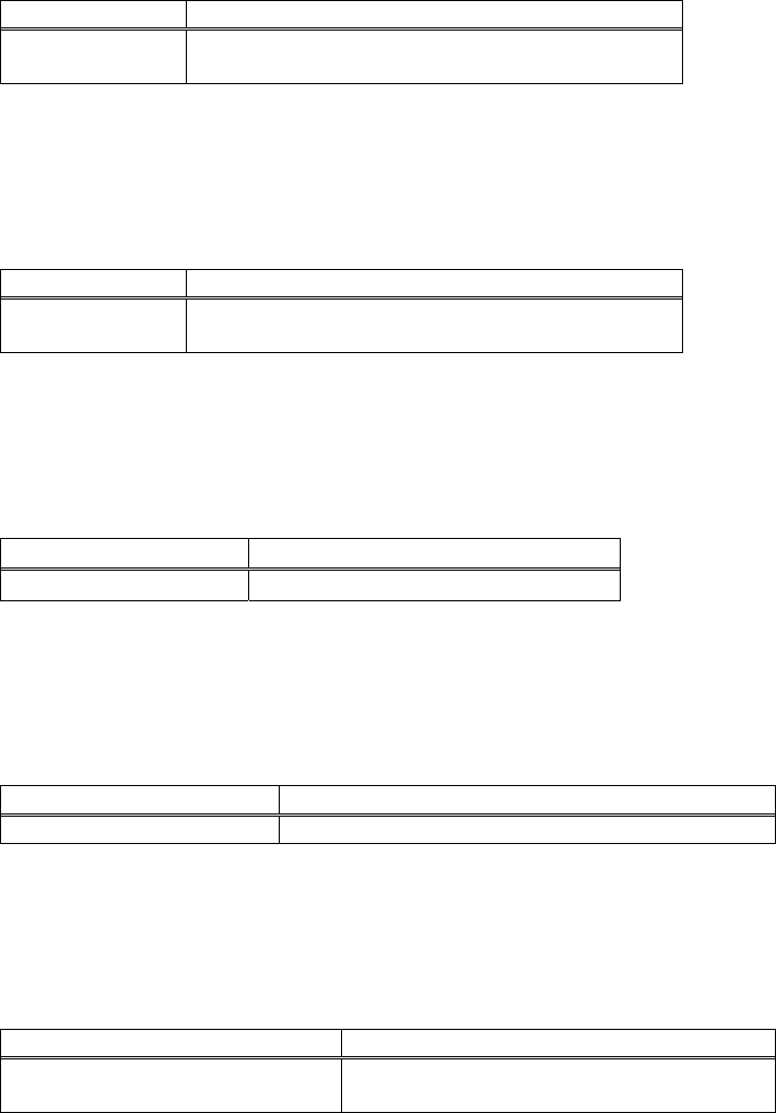
- 293 -
4.2.10 MSW10
●MSW10-1: Print density
[Outline] Select the print density.
Setting Value
Print Density 70%,75%,80%,85%,90%,95%,100%,105%,
110%,115%,120%,125%,130%,135%,140%
●MSW10-2: Print speed
[Outline] Select the print speed.
Setting Value
Print Speed Level1,Level2,Level3,evel4,Level5,Level6,
Level7,Level8,Level9
●MSW10-3: ACK output timing
[Outline] Select the ACK signal output timing in parallel interface.
Setting Value
ACK Timing Before Busy,Same Period , After Busy
●MSW10-4: user NV memory capacity
[Outline] Specify user NV memory capacity.
Setting Value
NV User 1Kbytes,64Kbytes,128Kbytes,192Kbytes
●MSW10-5: NV graphics memory capacity
[Outline] Specify NV graphics memory capacity.
Setting Value
NV Graphic 0bytes,64Kbytes,128Kbytes,192Kbytes,
256Kbytes,320Kbytes,384Kbytes
- 294 -
5. APPENDIX
5.1 Explanation on PAGE MODE
5.1.1 Overview
The printer has two print modes: STANDARD and PAGE.
In STANDARD MODE, the printer prints or feeds paper each time it receives a print or paper feed command. In
PAGE MODE, when the printer receives print commands and/or form feed commands, it simply forwards them to
the specified print area of memory. Only when an ESC FF or FF is executed all the data mapped in the print area will
then be printed in a batch.
For example, suppose you executed a print and line feed for data “ABCDEF”<LF>. In STANDARD MODE, the data
“ABCDEF” is printed and paper is advanced one line. In PAGE MODE, the data “ABCDEF” is written in the specified
print area of memory, and the memory location for the storage of the next print data is shifted one line.
The printer enters PAGE MODE with an ESC L, so that all commands received after that point are handled in PAGE
MODE. When an ESC FF is executed, the data received until then is printed in a batch. When an FF is executed, the
data received until then is printed in a batch, after which the printer returns to STANDARD MODE. An ESC S causes
the printer to immediately return to STANDARD MODE; any print data, however, that has been stored in PAGE
MODE is not printed. Instead it will be cleared.
PAGE MODE
ESC L
ESC FF
Print
STANDARD MODE
ESC S
FF
Print
[Switching Between STANDARD MODE and PAGE MODE]
5.1.2 Values Set by Each Command in STANDARD MODE and PAGE MODE
(1) The values set with commands are common to the STANDARD MODE and PAGE MODE. The values set with
any of the commands listed below are, however, treated differently and stored separately for the STANDARD
and PAGE MODES.
• ESC SP, ESC 2, ESC 3, FS S
(2) The maximum printable size of a bitmap image is 576 dots for STANDARD MODE. In PAGE MODE, the
maximum printable size of a bitmap image is 831 dots in the “y” direction (paper feed direction). (However 831
dots are reserved for “y” of the print area set by ESC W and the value of print direction “n” specified by ESC T is
1 or 3.)
- 295 -
5.1.3 Mapping of Print Data in the Print Area
Print data is mapped in the print area as follows:
(1) The print area is set by ESC W. When the printer has finished all of the print and paper feed actions specified
before receiving an ESC W, the ESC W sets the right end (as viewed facing the printer) as the start point (x0,
y0) of the print area. The print area is a rectangle defined by two edges extending from the start point (x0, y0):
one edge running in the “x” (Horizontal) direction by “dx” pitch (inclusive of the start point), and the other
running in the “y” (Vertical) direction by “dy” pitch. (If no ESC W is defined, the default values are used to
define the print area.)
(2) With a print area defined by ESC W and a print direction specified by ESC T, when the printer receives print
data, the print data is mapped in the print area where point A (see the Figure 4-1 “Mapping Position for
Character Data”) is used as the initial value of the start point. If the print data consists of characters, this start
point serves as the baseline.
If the print data is a downloaded bitmap image or a bar code, the print data is mapped with its lower-left point
B aligned to the baseline. (See the Figure 4-2 “Mapping Positions for Print Data”.) When attempting to map the
HRI characters of a bar code, however, the section above the standard character height will not be printed.
(3) If print data (or the space to the right of a character) extends beyond the print area before a command that
involves a line feed (for example, LF or ESC J command) is received, a line feed is automatically executed in the
print area, so that the mapping position of the print data is moved one line. The next mapping position will be
the beginning of the line. In this case, the line feed width is as defined by a command such as ESC 2 or ESC 3.
(4) By default, the line feed width is 1/6 inch, which is equivalent to 34 dots. If the print data for the next line
includes a vertically doubled or taller character, a downloaded bitmap image extending two or more lines, or a
bar code taller than the character height, the data, therefore, falls short of the line feed width, causing the
upper dots of the character to overlap the print data of the current line. The line feed width needs to be
increased.
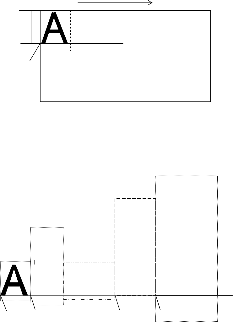
- 296 -
Mapping direction
Baseline
Print area dx, dy
x0, y0
2
4
-3
Point A
Figure 5-1 Mapping Position for Character Data
Double height character
24*2-6 42
Bit image
nH*256+n
ESC * m nL nH
6*8=48
Downloaded bit image
GS * x y
Bar cod
e
GS k m
(HRI Characters)
GS h n
24-3
3 6
1
1
x*8
2
Point B Point B Point B Point B
Baseline
Figure 5-2 Mapping Positions for Print Data
- 297 -
5.1.4 Example of Using PAGE MODE
The following explains specific uses of PAGE MODE.
When in PAGE MODE, the commands are typically sent from the host to the printer in the following sequence:
(1) An ESC L puts the printer in PAGE MODE.
(2) An ESC W specifies the print area.
(3) An ESC T specifies the print direction.
(4) Print data is sent.
(5) An FF instructs the printer to print the print data in a batch.
(6) After printing, the printer returns to STANDARD MODE.
< Example 1 >
100 PRINT #1,CHR$(&H1B);"L";
110 PRINT #1,CHR$(&H1B);"W";CHR$(0);CHR$(0);CHR$(0);CHR$(0);
120 PRINT #1,CHR$(200);CHR$(0);CHR$(144);CHR$(1);
130 PRINT #1,CHR$(&H1B);"T";CHR$(0);
140 PRINT #1,"Page mode lesson Test1"
150 PRINT #1,CHR$(&HC);
The program in Example 1 reserves a print area of 200 400 pitches extending from the start point (0, 0), and
then prints the text “Page Mode lesson Test 1” on the first line of the print area as shown in Figure 5-3
“Example 1: Results of Print”.
Page mode lesson
Test1
Print area
Paper
400
(
0
,
0
)
200
Print Direction
Figure 5-3 Example 1: Results of Print
- 298 -
In Figure 4-3, a line feed occurs between “lesson” and “Test 1” because the space “ “ next to “lesson” does not
fit in the horizontal range of the 200 400-pitch print area. The line feed width conforms to the value specified by
a command such as ESC 3.
It is possible to set as many print areas as desired before executing FF. If print areas overlap each other, the
print area setup data are ORed with the previous data.
If you want to erase a section of mapped data, use the CAN command. The CAN command erases all data in
the print area being specified. You can, therefore, use an ESC W to define a print area that encloses the section
you want to erase, and then execute the CAN command, so that the section of the data is erased.
It is important to remember that any part of a character that overlaps with the specified print area will be
erased.
< Example 2 >
100 PRINT #1,CHR$(&H1B);"L";
110 PRINT #1,CHR$(&H1B);"W";CHR$(0);CHR$(0);CHR$(0);CHR$(0);
120 PRINT #1,CHR$(200);CHR$(0);CHR$(144);CHR$(1);
130 PRINT #1,CHR$(&H1B);"T";CHR$(0);
140 PRINT #1,"Page mode lesson2CAN command";
150 PRINT #1,CHR$(&HA);
160 PRINT #1, "ABCDEFGHIJKLMNOPQRST1234567890";
170 PRINT #1,CHR$(&HC);
First, an ESC L is sent to switch to PAGE MODE (100th line). Next, an ESC W is used to send eight arguments, n1
to n8, to reserve a print area. In this example, the arguments are sent in the sequence of 0, 0, 0, 0, 200, 0, 144,
and 1, to reserve a print area that measures 200 from the start point (0, 0) in the “x” direction and 400 in the “y”
direction (110th to 120th line). Furthermore, an ESC T is issued to specify the print direction to be “0” (130th
line).
After the above setup, print data is sent (140th to 160th line). Finally, an FF is sent (170th line) to produce a
print-out as shown in Figure 5-4 “Example 2: Result of Print”.
- 299 -
Page mode lesson
2CAN command
ABCDEFGHIJKLMNOP
QRST1234567890 Print area
400
(
0
,
0
)
200
Print Direction
Paper
Figure 5-4 Example 2: Result of Print
Before an FF is sent (170th line), the following program code can be added to remove part of the data.
< Example 2 >
180 PRINT♯1,CHR$(&H1B);"W";CHR$(72);CHR$(0);CHR$(120);CHR$(0);
190 PRINT♯1,CHR$(36);CHR$(0);CHR$(48)CHR$(0);
200 PRINT♯1,CHR$(&H18);
As a result of the additional program code, a print-out is executed as shown in Figure 5-5 “Print Result of Adding
a Program of Example 3 to Example 2”, where the string “GHI” is removed.
When strings are removed with CAN, the area where the string would have been is not used by the rest of the
data, instead it is converted into a sequence of spaces.
- 300 -
Page mode lesson
2CAN command
ABCDEF JKLMNOP
QRST1234567890
400
(
0
,
0
)
200
Paper
Print area
Print Direction
Figure 5-5 Print Result of Adding a Program of Example 3 to Example 2
- 301 -
5.2 Bidirectional Parallel Interface
Overview
The interface of the printer is a Level-1 compatible device according to IEEE-P1284. It supports the communication
modes described in 5.2.1 below.
5.2.1 Parallel Interface Communication Mode
The parallel interface of the printer provides three communication modes as outlined below. When the printer is
turned on or reset, it defaults to Compatibility mode.
• Compatibility Mode
Data is transmitted from the host to the printer in units of one byte. Usually, this mode is used for data
transmission. You may switch to the other modes from Compatibility mode.
• Nibble Mode
Data is transmitted from the printer to the host in units of four bits. The data transmission from the printer uses
a status signal line. To send one byte of data in this mode, two sets of four-bit data are sent consecutively.
• Byte Mode
Data is transmitted from the printer to the host in units of one byte. Data transmission from the printer uses an
8-bit data signal line. For Byte mode, the host must be capable of toggling the signal direction over the 8-bit data
signal line. Communication from the host to the printer is called Forward mode, while communication from the
printer to the host is called Reverse mode.
- 302 -
5.2.2 Interfacing Phases
Interfacing in each communication mode is divided into several phases. In addition, there is a phase for mode
initialization, as well as a phase for mode switching. Interface signals may differ in name and function for different
modes and different phases.
Aborted
Transfer
Termination from
Other Modes
(except EPP)
Compatibility Mode
Host Xmits
Data
*Forward Forward Idle
Data
Transfer
End forward
Data Xfer
Termination
Event 1
Failed
Negotiation
Event 6
Negotiation
Event 6
Event 11
Host Busy
Event 11
Reverse
Data
Transfer
Host Busy
Data
Available
Event 7
Event 18
Reverse
Idle
Interrupt
Host
Event 21
Data Not
Available
Event 7
- 303 -
5.2.3 Negotiation
Overview
Usually, the printer is started in Compatibility mode, which corresponds to the Centronics interface phase.
When the host intends to switch to the Nibble or Byte mode, it sends a request and negotiates with the printer. A
general flow of negotiations is given below.
(1) The host sets the IEEE 1284 Active signal to High. In response, the printer moves into the Negotiation
phase.
(2) The printer replies whether it can execute the mode requested by the host.
(3) The interface terminates the Negotiation phase and moves into the communication phase.
Negotiation Procedure
The negotiations proceed as follows:
(1) In IEEE 1284 communication mode, the host and printer are in Compatibility mode by default. They remain in
Compatibility mode as long as the host recognizes the connected device as an IEEE 1284 compatible device.
(2) To start negotiations, the host sets the communication mode request bit on the data path. (Event 0)
(3) The host sets IEEE 1284 Active (nSelectln) to High, and HostBusy (nAutoFd) to Low. (Event 1)
(4) The printer responds by setting PtrClk (nAck) to Low, nDataAvail (nFault) to High, Xflag (Select) to High, and
AckDatReq (PError) to High. (Event 2)
(5) The host sets HostClk (nStrobe) to Low. In response, the printer latches the data of the communication mode
request bit. (Event 3)
(6) The host sets HostClk (nStrobe) and HostBusy (nAutoFd) to High. (Event 4)
(7) If the printer has communication data to send to the host, it sets AckDataReq (PError) to Low, nDataAvail
(nFault) to Low, and Xflag (Select) to the value corresponding to the communication mode. (Event 5)
Xflag: Nibble Mode : Low
Byte Mode : High
(8) The printer sets PtrClk (nAck) to High to indicate that it is ready to read status lines. (Event 6)
(9) If the printer has communication data to send to the host, the host moves into the Host Busy Available phase
or Termination phase, and then returns to the Compatibility mode.
(10) If the printer has no communication data to send to the host, the host moves into the Host Busy Data Not
Available phase or Termination phase, and then returns to the Compatibility mode.
(11) If the printer cannot support the communication mode requested by the host, it sets Xflag (Select) as follows:
When Nibble mode is requested : High
When Byte mode is requested : Low

- 304 -
Precautions
(1) The Negotiation phase is triggered when the IEEE 1284 Active signal sent by the host becomes High.
(2) In Compatibility mode, the time when the negotiation process begins is, as a general rule, after the host sets
nStrobe to High and then the printer outputs an nAck pulse.
Once the nStrobe signal is set to High, however, the printer immediately moves into the Negotiation phase
when the high state of IEEE 1284 Active is detected, even if the nAck pulse has yet to be output or is being
output. In this case, if the printer has returned to Compatibility mode after Termination, no nAck pulse will be
output.
(3) Negotiations can be entered from the Busy or Error state of the Compatibility mode. In this case, the printer will
not return to the Busy or Error state before the negotiations, but still remains in the printer state just after
Termination.
(4) If the host requested a communication mode that is not supported by the printer, it must move into the
Termination phase and return to the Compatibility mode.
Table Definitions of Request Bits in IEEE 1284 Communication Mode
Xflag
bit Definition Bit Values
(76543210)Hex Code When
Supported
In the
Printer
7 Request Extensibility Link 10000000 80H High Low
6 Request EPP Mode 01000000 40H High Low
5 Request ECP Mode with RLE 00110000 30H High Low
4 Request ECP Mode 00010000 10H High Low
3 Reserve 00001000 08H High Low
2
Request Device ID:Return Data Using
Nibble ModeRev Channel Transfer
Byte Mode Rev Channel Transfer
ECP Mode Transfer without RLE
ECP Mode Transfer with RLE
00000100
00000101
00010100
00110100
04H
05H
14H
34H
High
High
High
High
High
High
Low
Low
1 Reserve 00000010 02H High Low
O Byte Mode Reverse Channel Transfer 00000001 01H High High
non Nibble Mode Reverse Channel Transfer 00000000 00H Low Low
Illegal or Contradictory Request Other than
above
Other than
above -- Low
The printer only supports the Nibble and Byte modes. For a request for any other mode, Xflag is set to Low.
- 305 -
Data Communication from Printer to Host
Nibble Mode
In this mode, data is transferred between the printer and the host through the procedure described below.
The steps beginning from (1) are applicable when the Negotiation phase has switched to the Host Busy Data
Available phase. If the Negotiation phase has switched to the Host Busy Data Not Available phase, the procedure
starts at step (9).
(1) After the negotiations for the entry into Nibble mode are completed, the host sets HostBusy (nAutoFd) to
Low to indicate that it is ready to receive data from the printer. (Event 7)
(2) The printer places the low-order four bits on the reverse channel data line and sets PtrClk (nAck) to Low.
(Events 8 and 9)
(3) The host sets HostBusy (nAutoFd) to High to indicate that it has latched data and received the signal in
Event 9. (Event 10)
(4) The printer sets PtrClk (nAck) to High. This completes transfer of the first nibble. (Event 11)
(5) Steps (1) to (3) are repeated to transfer the high-order four bits, before proceeding to steps (6) and on.
(6) After the host has set HostBusy (nAutoFd) to High (Event 10) and received data, the printer must set the
four status lines as shown below. (Event 13)
• PtrBusy (Busy) : Returned to the status given in Forward mode.
• nDataAvail (nFault) : Set to Low if there is data to be sent.
• AckDataReq (PError) : Set to Low if there is data to be sent.
• Xflag (Select) : Set to the current mode (i.e., set to Low).
(7) The printer sets PtrClk (nAck) to High. (Event 11)
(8) After Event 11, the host checks the signals set by the printer in Event 13. With this check the host
determines:
1. Whether there is more data to be sent from the printer to the host;
2. And whether data can be transferred from the host to the printer.
(9) If there is no more data to be sent from the printer after the transfer of one byte (two nibbles), the host
chooses one of three status selections:
1. Performing Termination and returning to the Compatibility mode.
2. Remaining in the Host Busy Data Not Available phase.
3. Setting HostBusy (nAutoFd) to Low (Event 7) and moving to the Reverse Idle phase.
(10) If there is more data to be received from the printer, the host chooses one of three status selections:
1. Setting HostBusy (nAutoFd) to Low and indicating that the host is ready to receive.
2. Remaining in the Host Busy Data Available phase.
3. Performing Termination and returning to the Compatibility mode.
(11) If the host selected the Host Busy Data Available phase and set HostBusy (nAutoFd) to Low, the printer
repeats the steps from (2) onwards.
(12) If the host selected the Reverse Idle phase and new data becomes available to be sent from the printer,
the printer sets PtrClk to Low to request the host for an interrupt. (Event 18)
(13) The printer sets PtrClk back to High. (Event 19)
- 306 -
(14) Upon receiving a request for interrupt from the printer, the host responds by setting HostBusy (nAutoFd) to
High. (Event 20)
(15) Finally, the printer responds to the host by setting AckDataReq (PError) to Low, and then the host moves to
the Host Busy Data Available phase. (Event 21)
- 307 -
Byte Mode
In this mode, data is transferred between the printer and the host through the procedure described below.
The steps beginning from (1) are applicable when the Negotiation phase has switched to the Host Busy Data
Available phase. If the Negotiation phase has switched to the Host Busy Data Not Available phase, the procedure
starts at step (9).
(1) After the negotiations for the entry into the Byte mode are complete, the host indicates that it is ready to
receive data from the printer. This is indicated by switching the data bus to a high-impedance state and setting
HostBusy (nAutoFd) to Low. (Events 14 and 7)
(2) The printer places communication data on the data bus. (Event 15)
(3) The printer sets PtrClk (nAck) to Low. (Event 9)
(4) The host sets HostBusy (nAutoFd) to High to indicate that it has latched data and received the signal in Event 9.
(Event 10)
(5) The printer must set the four status lines as shown below. (Event 13)
• PtrBusy (Busy): Returned to the status given in the Forward mode.
• nDataAvail (nFault): Set to Low if there is data to be sent.
• AckDataReq (PError): Set to Low if there is data to be sent.
• Xflag (Select): Set to the status given during the last negotiation (i.e., set to Low).
(6) The printer sets PtrClk (nAck) to High (Event 10) and ends the Byte handshake. (Event 11)
(7) The host indicates that it has succeeded in receiving the data. This is indicated by setting HostClk (nStrobe) to
Low (Event 16) and then to High. (Event 17)
(8) Events 10 and 16 may occur simultaneously, and Events 7 and 17 may occur simultaneously. (Such as when
HostBusy and HostClk are used together.)
(9) After transferring one byte of data, the printer signals to the host whether it has more data to transfer. When
there is no more data to be received by the host from the printer, the host chooses one of three status
selections:
1. Performing Termination and returning to the Compatibility mode.
2. Remaining in the Host Busy Data Not Available phase.
3. Setting HostBusy (nAutoFd) to Low and moving to the Reverse Idle phase. (Event 7)
(10) When more data is to be received from the printer, the host chooses one of three status selections:
1. Setting HostBusy (nAutoFd) to Low and indicating that the host is ready to receive.
2. Remaining in the Host Busy Data Available phase.
3. Performing Termination and returning to the Compatibility mode.
- 308 -
Device ID
The device ID is a character string that provides the ID, the type, and other information regarding the printer
connected to the interface. When the printer receives a request for a device ID from the host, it replies with the
following device ID:
<00>H<2E>H
MFG:CITIZEN;
CMD:ESC/POS;
MDL:CT-S300;(*)
CLS:PRINTER;
*This value differs by model and model name is returned.
The first two bytes of the device ID indicate the length of the entire device ID. For a description of a request for a
device ID, refer to the “Negotiation” section.
When the host receives the device ID string of the length indicated by the first two bytes, it must do so
consecutively, without terminating the process until the entire device ID is received. If the process is terminated
halfway, the printer discards the rest of the string; when the printer receives a new request for the device ID, it
sends the device ID beginning from the first character of the ID. After receiving the ID of the length indicated by
the first two bytes, the host must carry out the termination even if the printer has data to send (Data Available). If
the host does not carry out Termination and tries to receive data, the printer sends the printer status.
- 309 -
Termination
Termination is the process of returning to Compatibility mode from the Nibble or Byte modes. When performing
Termination, the host sets the signals as follows:
• IEEE 1284 Active (nSelectln): Low
• HostBusy (nAutoFd): High (Event 22)
There are two methods of Termination:
(1) Termination through a handshake between the host and the printer
(2) Immediate termination
(1) Termination through a handshake between the host and the printer:
When switching from Reverse mode to Compatibility mode, this termination method can be used if the
interface is activated (IEEE 1284 Active: High) and Event 22 has taken place.
1) The printer responds to IEEE 1284 Active by setting PtrBusy (Busy) and nDataAvail (nFault) to High.
(Event 23)
2) The printer then inverts Xflag (Select) and sets PtrClk (nAck) to Low. (Event 24)
3) The host sets HostBusy (nAutoFd) to Low. (Event 25)
4) The printer returns nDataAvail (nFault), Xflag (Select), and AckDataReq (PError) to the status given in the
Compatibility mode, and sets PtrClk (nAck) to High. (Events 26 and 27)
5) The host sets HostBusy (nAutoFd) to High to terminate the handshake and return the interface to the
Compatibility Mode Idle phase. (Event 28)
6) The printer changes PtrBusy (Busy) to be able to receive data from the host.
(2) Immediate termination:
1) If the interface is deactivated (IEEE 1284 Active: Low) without Event 22 having taken place, the printer
immediately performs Termination. In this termination, the data is not guaranteed, and the printer switches
the data bus from output to input within 1 µsec.
In the Reverse Idle phase, the printer can notify the host that it has data to transfer to the host. The
notification may occur simultaneously with termination in order for the host to move from the Idle phase to
the Compatibility mode.
If the printer has data to send, it initiates the Interrupt phase indicated by Events 8 and 9. In this case, if
1284 - Active (nSelectIn) was set to Low before HostBusy (nAutoFd) changed from High to Low, the printer
interprets that the host has switched to the Termination phase, and then completes the normal termination
through handshaking.

- 310 -
5.3 Identification of Send Status
Because the status sent from the printer has certain fixed bits, it is possible to identify to which command the status
belongs.
When using ASB (Automatic Status Back), however, the first byte of ASB should be checked, and then the three
consecutive bytes except for XOFF should be treated as ASB data.
Identification of Send Status
Command and Function Status
GS I <0**0****>B
GS r <0**0****>B
XON <00010001>B
XOFF <00010011>B
DLE EOT <0**1**10>B
ASB (1st byte) <0**1**00>B
ASB (2nd - 4th bytes) <0**0****>B
- 311 -
If printing of “E” of 2 times vertical (48 dots) is
attempted there, 48 dots are not printed in the
remaining area of 36 dots. Therefore, “E” is
printed from next label’s first print position.
Here, line feed of “E” must also be included in the
calculation of the height of “E”. (See figure below.)
5.4 Cautions on Black Mark/Label Paper
Cautions on LF (CR), ESC J, ESC d, Page mode, Image, and barcode printing.
Printing of image greater than vertical print area of BM paper/label paper used is prohibited as a rule.
The user must use label while taking label size into account at all times and terminate printing of a sheet
of label with FF, ESC FF or GS FF.
AAAAAAAAAAAAAAAAAAA
BBBBBBBBBBBBBBBBB
CCCCCCCCCCCCCCCCC
DDDDDDDDDDDDDD
EEEEEEEEEE
After printing of “D” in the left figure, remainder of
vertical print area must be 36 dots.
AAAAAAAAAAAAAAAAAA
BBBBBBBBBBBBBBBB
CCCCCCCCCCCCCCCCC
Only character can be printed here but printed on
next label
EEEEEEEEEEEEEEEEEE
EEEEEEEEEEEEEEEEEE
60 ドット
as feed amount cannot be applied.
As shown in the left figure, character height is 24
dots. If, however, line feed width is 60 dots by the
setting or command such as ESC 3 or the like,
vertical print area is calculated including line feed
width in character height. If printing in vertical
area is not available, printing is started from the
first print position of the next label.
The same principle applies to image and barcode.
Barcode and image are as shown on the next page.
- 312 -
If printing of image greater than inter-BM distance/label paper length (vertical print area width) is
attempted, image is printed in two separated images as shown below.
Barcode,
downloaded image,
NV image,
page mode
Image greater than vertical print area of label
paper used is printed over the label.
In this case, head and bottom margins must be
taken into account.
Printing occurs in two or more separate
areas.
Barcode, download, NV
ima
g
e
,
Pa
g
e mode
