Citizen Systems Idp3110 Users Manual UsersManual
iDP3110 iDP3110UME_20
iDP3110 to the manual feadc9e2-6320-4b32-87ef-a3daa17529f7
2015-02-05
: Citizen-Systems Citizen-Systems-Idp3110-Users-Manual-533767 citizen-systems-idp3110-users-manual-533767 citizen-systems pdf
Open the PDF directly: View PDF ![]() .
.
Page Count: 36

DOT MATRIX PRINTER
MODEL iDP3110

iDP3110 User's Manual
CITIZEN
Declaration of Conformity
Manufacturer’s Name : : Japan CBM Corporation
Manufacturer’s Address : CBM Bldg., 5-68-10, Nakano, Nakano-ku,
Tokyo, 164-0001, Japan
Declare the Product
Product Name Dot Matrix Printer
Model Number(s) iDP3110 Series
(iDP3110R, iDP3110P)
(S.No. 0090001 ~ )
Conform to the following Standards
LVD:EN60950:A4:1997
EMC : EN55022 : 1998 Class B
: EN61000-3-2 : 1995+A1:1998+A2:1998
: EN61000-3-3 : 1995
: EN55024 : 1998
: EN61000-4-2 : 1995 ±4KV CD, ±8KV AD
: EN61000-4-3 : 1996 4.5V/m, 80MHz-1000MHz AM 1KHz 80%
: EN61000-4-4 : 1995 ±1.0KV(AC Mains), ±0.5KV(Signal Lines)
: EN61000-4-5 : 1995 ±1KV (Normal mode), ±2KV (Common mode)
: EN61000-4-6 : 1996 3V, 0.15MHz-80MHz AM 1KHz 80%
: EN61000-4-8 : 1993 50Hz, 3A/m
: EN61000-4-11 : 1994 0%, 5000ms/ 70%, 500ms/ 0%, 10ms
Supplementary Information
“The product complies with the requirements of the Low Voltage Directive 73/23/EEC, 93/68/EEC and
the EMC Directive 89/336EEC, 92/31/EEC, 93/68EEC”
Place Tokyo, Japan Signature
Date September, 2000
Full Name : Mikio Moriya
Position : General Manager
R & D Department
Europe Contact :
Norco Declaration AB
Box 7146 S-250 07 Helsingborg Sweden
This declaration is applied only for 230V model.

iDP3110 User's Manual
CITIZEN
IMPORTANT SAFETY INSTRUCTIONS
* Read all of these instructions and save them for later reference.
* Follow all warnings and instructions marked on the product.
* Unplug this product from the wall outlet before cleaning. Do not use liquid or aerosol cleaners.
Use a damp cloth for cleaning.
* Do not use this product near water.
* Do not place this product on an unstable cart, stand of table. The product may fall, causing serious damage to the
product.
* Slots and openings on the cabinet and the back or bottom are provided for ventilation.
To ensure reliable operation of the product and to protect it from overheating, do not block or cover these
openings. The openings should never be blocked by placing the product on a bed, sofa, rug of other similar
surface.
This product should never be placed near or over a radiator or heat register.
This product should not be placed in a built-in installation unless proper ventilation is provided.
* This product should be operated from the type of power source indicated on the marking label.
If you’re not sure of the type of power available, consult your dealer or local power company.
* Do not allow anything to rest on the power cord. Do not locate this product where the cord will be walked on.
* In an extension cord is used with this product, make sure that the total of the ampere ratings on the products
plugged into the extension cord do not exceed the extension cord ampere rating.
Also, make sure that the total of all products plugged into the wall outlet dose not exceed 15 amperes.
* Never push objects of any kind into this product through cabinet slots as they may touch dangerous voltage points
or short out parts that could result in a risk of fire or electric shock. Never spill liquid of any kind on the product.
* Except as explained elsewhere in this manual, don’t attempt to service this product yourself.
Opening and removing those covers that are marked “Do Not Remove” may expose you to dangerous voltage
points or other risks. Refer all servicing on those compartments to service personnel.
* Unplug this product from the wall outlet and refer servicing to qualified service personnel under the following
conditions:
A. When the power cord or plug is damaged or frayed
B. If liquid has been spilled into the product.
C. If the product has been exposed to rain or water.
D. If the product dose not operate normally when the operating instructions are followed. Adjust only
those controls that are covered by the operating instructions since improper adjustment of other
controls may result in damage and will often require extensive work by a qualified technician to restore
the product to normal operation.
E. If the product has been dropped or the cabinet has been damaged.
F. If the product exhibits a distinct change in performance, indicating a need for service.

iDP3110 User's Manual
CITIZEN
IMPORTANT:
This equipment generates, uses, and can radiate radio frequency energy and if not installed and used in
accordance with the instruction manual, may cause interference to radio communications. It has been tested and
found to comply with the limits for a Class A computing device pursuant to Subpart J of Part 15 of FCC Rules,
which are designed to provide reasonable protection against such interference when operated in a commercial
environment. Operation of this equipment in a residential area is likely to cause interference, in which case the
user at his own expense will be required to take whatever measures may be necessary to correct the interference.
CAUTION: Use shielded cable for this equipment.
For Uses in Canada
This digital apparatus does not exceed the class A limits for radio noise emissions from apparatus, as set out in
the radio interface regulations of the canadian department of communications.
Pour L’utilisateurs Canadiens
Cet appareil numérique ne dépasse pas limites de carégorie a pour les émissions de bruit radio émanant
d’appareils numériques, tel que prévu dand les réglements sur l’interference radio du départment canadien des
communications.

iDP3110 User's Manual
CITIZEN
CONTENTS
1. INTRODUCTION .........................................................................................................................................1
1.1 Features ................................................................................................................................................................1
1.2 Accessories...........................................................................................................................................................1
2. TYPE CLASSIFICATIONS.......................................................................................................................... 2
2.1 Type......................................................................................................................................................................2
2.2 AC adapter............................................................................................................................................................2
2.3 Specifications .......................................................................................................................................................3
3. EXTERNAL APPEARANCE AND PART DESCRIPTION..........................................................................4
3.1 External Appearance ............................................................................................................................................4
3.2 Part Descriptions ..................................................................................................................................................5
4. OPERATIONS .............................................................................................................................................6
4.1 Connection of the AC Adapter .............................................................................................................................6
4.2 Setting of the Printer Cover..................................................................................................................................7
4.3 Setting of Ribbon Cassettes..................................................................................................................................8
4.4 Setting Paper.........................................................................................................................................................9
4.5 Self Test Printing................................................................................................................................................10
4.6 General Notices..................................................................................................................................................10
5. PARALLEL INTERFACE...........................................................................................................................11
5.1 Specifications .....................................................................................................................................................11
5.2 Connector Pin Assignment.................................................................................................................................11
5.3 Description of Input / Output Signals.................................................................................................................12
6. SERIAL INTERFACE ................................................................................................................................14
6.1 Specifications .....................................................................................................................................................14
6.2 Connector Pin Assignment.................................................................................................................................15
6.3 Description of Input / Output Signal ..................................................................................................................15
7. DIP SWITCH SETTING............................................................................................................................. 18
7.1 Serial Interface Type...........................................................................................................................................18
7.2 Parallel Interface Type........................................................................................................................................18
8. PRINT CONTROL FUNCTION ................................................................................................................. 19
8.1 Control Command..............................................................................................................................................19
9. CHARACTER SET....................................................................................................................................26
9.1 Character code....................................................................................................................................................26
10. EXTERNAL DIMENSIONS ..................................................................................................................... 29

iDP3110 User's Manual
CITIZEN 1
1. INTRODUCTION
The iDP3110 is a dot-impact printer suitable for use with various data communication terminals, and measurement
terminals.
This product is extremely compact and features extensive functions suited for a wide range of applications. Please
read this manual thoroughly to understand the printer before use.
1.1 Features
1. Compact desk-top dot matrix printer
2. Light weight
3. High speed printing
4. Low power consumption
1.2 Accessories
The following attachments are included in this set aside from the printer itself. Please confirm.
Paper roll (1 roll)
Ribbon cassette (1 unit)
AC adapter (1unit)
User’s manual (1 booklet)

iDP3110 User's Manual
CITIZEN 2
2. TYPE CLASSIFICATIONS
2.1 Type
The product is categorized according to the naming plan indicated below.
iDP3110 24
40
P
R
J
F
120
230
A
B
iDP3110 24 P J 120 A
Model Name
Printer cover
Number of columns A : 60mm(Dia.)
24 : 24 columns/144 dots Paper roll
40 : 40 columns/180 dots B : 80mm(Dia.)
Paper roll
Power source
120 : AC 120V
230 : AC 220-240V
Interface
P : Parallel (Centronics)
R : Serial (RS-232C) Character
J : Japanese
F : International
2.2 AC adapter
Please use the exclusive adapter indicated below.
90AD-U (AC 120V)
90AD-E (AC 220-240V)

iDP3110 User's Manual
CITIZEN 3
2.3 Specifications
Item iDP3110-24* iDP3110-40*
1 Printing method Dot matrix
2 Printing direction One-way printing
3 Character configuration
(5 + 1) × 8 (4 + 0.5) × 8
(W × H)
4 Number of columns per line 24 columns: 144 dot/line 40 columns: 180 dot/line
5 Printing speed Approx. 2.5 line/sec. Approx. 1.8 lines/sec.
6 Character size (W × H) 1.6 × 2.4 mm 1.08 × 2.4 mm
7 Line pitch 3.52 mm
8 Paper Paper Roll 57.5 ± 0.5(W) × 60 (Dia) mm
57.5 ± 0.5(W) × 80 (Dia) mm
9 Interface Type P: Parallel Interface (Centronics)
Type R: Serial Interface (RS-232C)
10 Ribbon cassette Exclusive ribbon cassette
Purple print : IR-91P
Black print : IR-91B (Option)
11 Voltage DC 7V ± 1V (Printing)
Use exclusive adapter (DC 7V, 1.2A)
12 Power consumption Printing : approx. 7VA
Stand-by : approx. 0.5VA
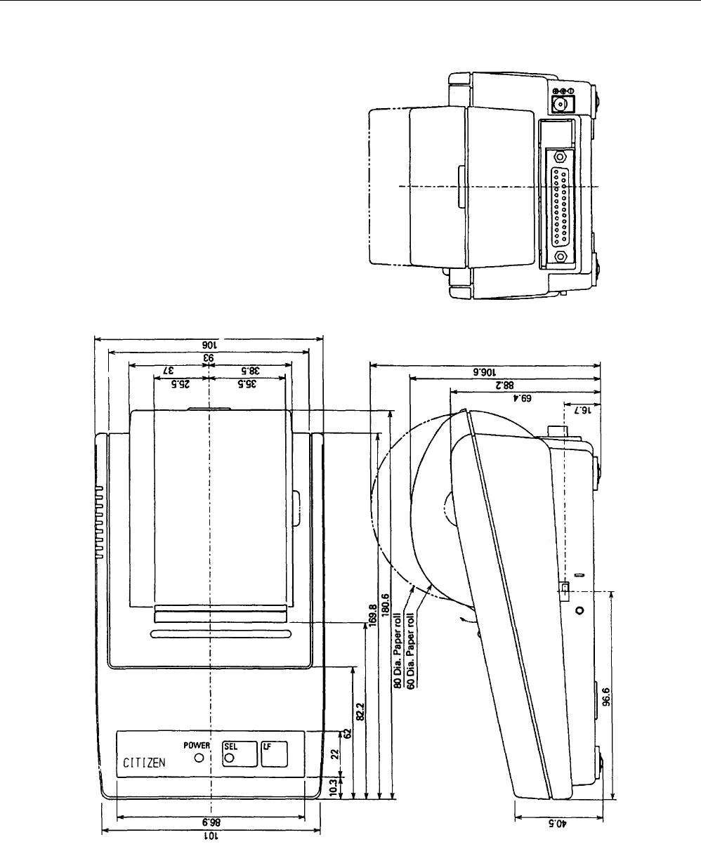
13 Weight Approx. 400g
14 Dimension 106(W) × 180(D) × 88(H) mm (60 Dia. Paper Roll)
106(W) × 180(D) × 106(H) mm (80 Dia. Paper Roll)
15 Operating temp. 0°C to 40°C
16 Storage temp -20°C to 60°C
iDP3110 User's Manual
CITIZEN 4
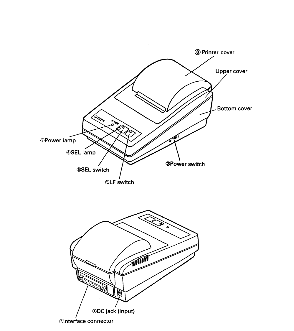
3. EXTERNAL APPEARANCE AND PART DESCRIPTION
3.1 External Appearance

iDP3110 User's Manual
CITIZEN 5
3.2 Part Descriptions
1. DC Jack Insert the output plug of the AC adapter attached.
2. Power Switch When switched ON, power is supplied to the printer, starting the initializing operation.
3. Power Lamp Lighted when power is turned ON and goes out when turned OFF.
4. SEL Lamp Lighted when printer is in the selected condition (ON-LINE).
Printer becomes operational only when this lamp is on.
5. LF Switch Paper is fed when switch is pressed (de-select condition only). Used to supply paper or to
insert some space in the output.
6. SEL Switch Printer is selected (ON-LINE) by pressing this switch.
Printer is de-selected (OFF-LINE) by pressing the switch again.
7. Interface Connector Printer is connected to various hosts via cables.
Please ensure that both the printer and the host are turned off before connecting.
8. Printer Cover Opened to exchange ribbon cassette and paper roll.
iDP3110 User's Manual
CITIZEN 6
4. OPERATIONS
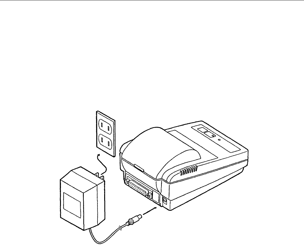
4.1 Connection of the AC Adapter
(1) Ensure that the power switch is OFF.
(2) Insert the output plug of the AC adapter into the DC jack of the printer.
(3) Insert the power plug of the AC adapter into a power concent supplying the designated voltage.
(Use of exclusive AC adapter is recommended. Output is DC 7V, 1.2A. Avoid using power sources not conforming to
this specification.)
iDP3110 User's Manual
CITIZEN 7
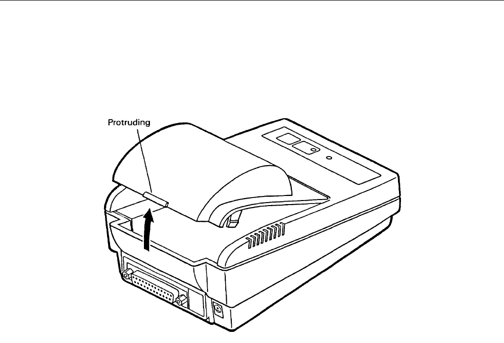
4.2 Setting of the Printer Cover
(1) Hold the protruding section at the rear of the printer cover and lift in the direction indicated.
(2) Attach the cover by pressing downward after hooking the cover to the acceptor located in the front part.
iDP3110 User's Manual
CITIZEN 8
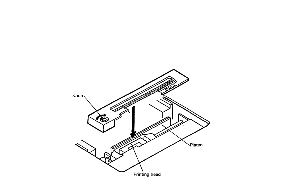
4.3 Setting of Ribbon Cassettes
(1) Remove the printer cover after turning OFF the printer.
(2) Press down on the Ribbon cassette while inserting the ribbon between the printing head and the platen.
(3) Wind up the ribbon slack by turning the knob in the direction of the arrow.
iDP3110 User's Manual
CITIZEN 9
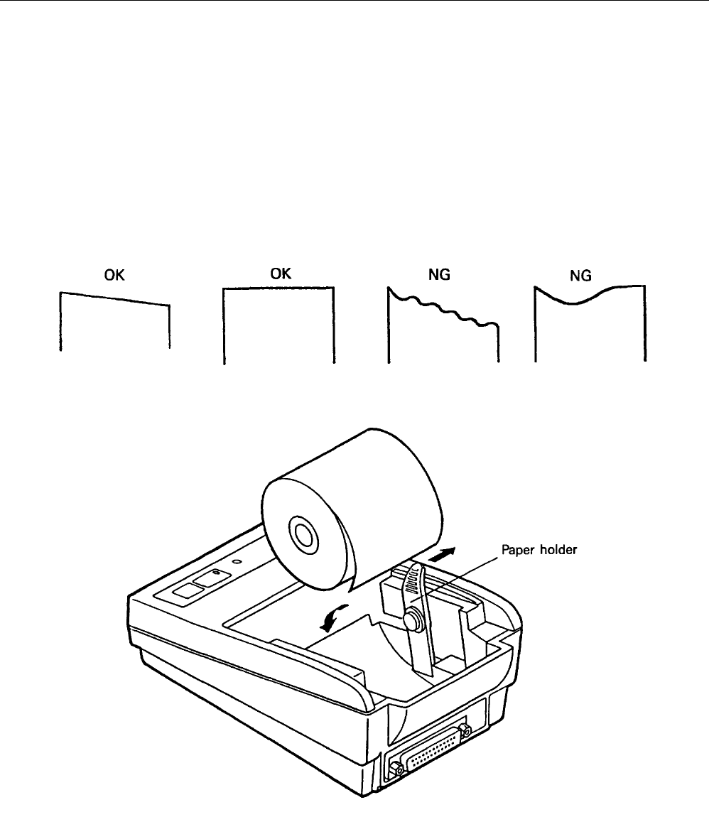
4.4 Setting Paper
(1) Remove the printer cover.
(2) Ensure that the end of the paper is straight or incline as indicated in the diagram.
(3) Insert the end of the paper into the slot of the printer mechanism.
(4) After turning ON the printer, press the LF switch until 5 to 6 cm of paper is fed out of the printer mechanism.
(5) Insert paper after moving aside the paper holder in the direction of the arrow. Then, secure the center of the roll
with the holder.
(6) Then, attach the printer cover so the end of the paper comes out of the opening in the cover.

iDP3110 User's Manual
CITIZEN 10
4.5 Self Test Printing
A self-printing function is incorporated in this product to enable the printer to check itself.
This function is triggered by the following procedure.
(1) Set paper to the printer.
(2) Ensure that the ribbon cassette is attached correctly and turn the power OFF.
(3) Turn ON the power switch while holding the LF switch down. Release the LF switch after the self-printing
operation has started.
Printing is initiated by this operation. To end self-printing, turn OFF the printer.
4.6 General Notices
(1) Never operate your printer without loading paper and ribbon cassette. Any printing without paper and ribbon
cassette may cause damage to printer head.
(2) Replace ribbon cassette before it is worn with rents.
(3) Be careful not to drop any foreign matters, such as paper clips and pin and the like into your printer.
Those can cause mechanical trouble.
(4) Nothing shall be placed on the radiation vents to the printer.
(5) Place your printer always on a stable desk which is set horizontal.
(6) No organic solvent (thinner, benzin or the lie) shall be used in sweeping clean the surface of the main body case.
(7) Make sure that the power of the printer is turned off whenever you do the following.
1) Taking out any foreign matter which was dropped into the printer.
2) Replacing the ribbon cassette.
iDP3110 User's Manual
CITIZEN 11
5. PARALLEL INTERFACE
5.1 Specifications
a) Data input system : 8 bit parallel (DATA 1-8)
b) Control signal : ACK, BUSY, STB, RESET, SELECT
c) Compatible Connector : Printer side : 57LE-40360
(AMPHENOL or equivalent)
: Cable side : 57-30360
(AMPHENOL or equivalent)
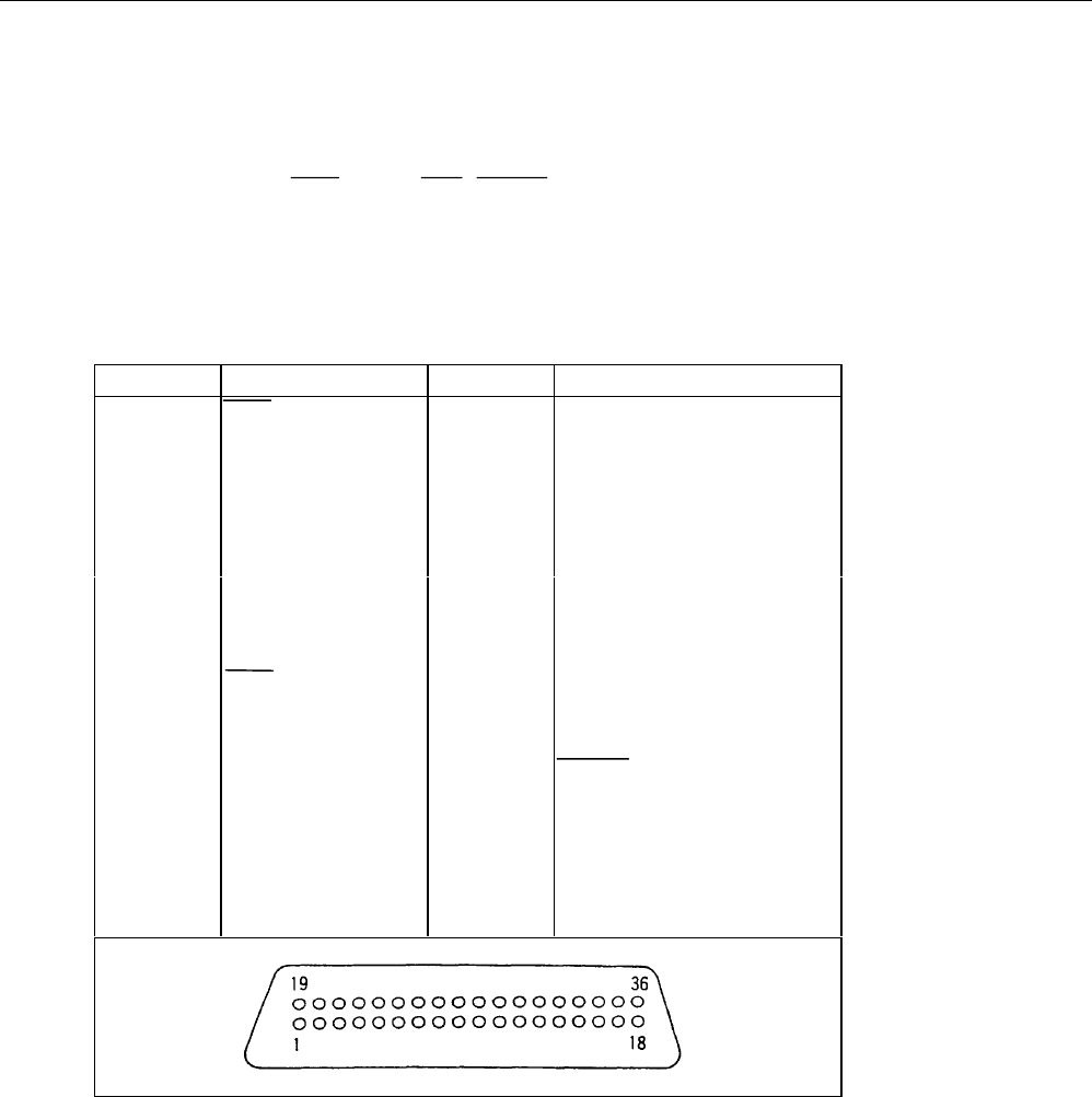
5.2 Connector Pin Assignment
PIN SIGNAL NAME PIN SIGNAL NAME
1 STB 19 TWISTED PAIR GND
2DATA1 20 ″
3 ″ 2 21 ″
4 ″ 3 22 ″
5 ″ 4 23 ″
6 ″ 5 24 ″
7 ″ 6 25 ″
8 ″ 7 26 ″
9 ″ 8 27 ″
10 ACK 28 ″
11 BUSY 29 ″
12 GND 30 GND
13 SELECT 31 RESET
14 GND 32
15 33 GND
16 GND 34
17 FRAME GND 35
18 36
iDP3110 User's Manual
CITIZEN 12
5.3 Description of Input / Output Signals
(1) Input signal
All input signals utilize type 74HC of CMOS and can be used in TTL level as the input is pulled up with 3.3 kΩ
resistance.
- DATA 8 bit parallel signal (positive logic)
- STB Strobe signal for reading out data (negative logic)
- RESET Signal for resetting the entire unit (negative logic 4ms or more)
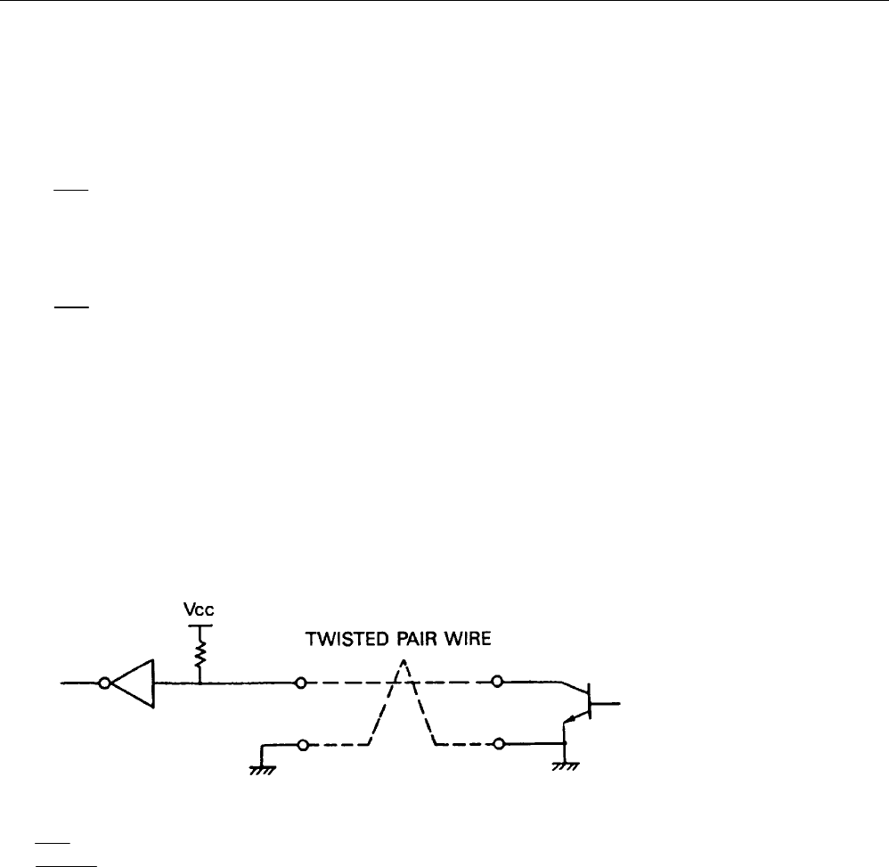
(2) Output signal
TTL is utilized for all output signals. The output is pulled up with 3.3 kΩ resistance.
- ACK Signal for requesting data. ACK is issued at the end of the BUSY signal (negative logic)
- BUSY Signal indicating the printer is busy. Input new data when the signal is in “LOW”
condition.(positive logic)
- SELECT Signal indicating the printer is set to a selected condition (on-line). “HIGH” state signifies the
printer is selected.
(3) Others
- GND The common circuit ground.
- FG Equivalent to “case ground”.
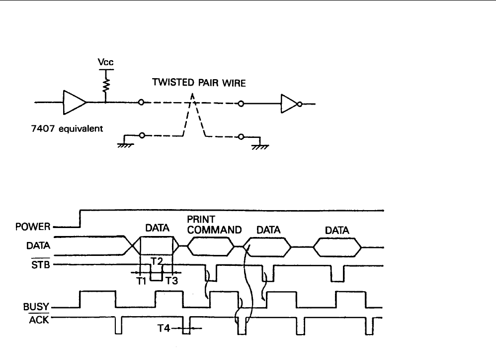
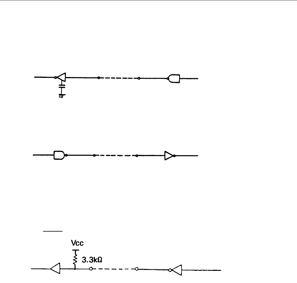
• Input
[ Printer side ] [ Host side ]
DATA : 74HC373 equivalent
STB : 74HC14 equivalent
RESET : 74HC04 equivalent
iDP3110 User's Manual
CITIZEN 13
• Output
[ Printer side ] [ Host side ]
(4) Timing chart
1) Timing for data entry and printing
T1 0.5 µs MIN
T2, T3 1 µs MIN
T4 2 µs TYPE
(5) Data receiving
Printer is capable of accepting data from the host while the BUSY signal is in the “LOW” state. Printer cannot
accept data when the signal is “HIGH”.

iDP3110 User's Manual
CITIZEN 14
6. SERIAL INTERFACE
6.1 Specifications
1) Synchronization : Asynchronous
2) Baud rate : User selection, 4,800; 9,600 Baud / sec
3) Word configuration : Start bit 1 bit
: Data bit 8 bit
: Stop bit More than 1 bit
4) Signal polarity
RS-232C
* Mark = Logic “1” (-3 to –12V)
* Space = Logic “0” (+3 to +12V)
TTL(RESET)
* H level = Logic “1” (refer to (3), section 6.3)
* L level = Logic “0”
5) Input control (DTR signal)
* Mark : Data transmission not possible
* Space : Data transmission possible
iDP3110 User's Manual
CITIZEN 15
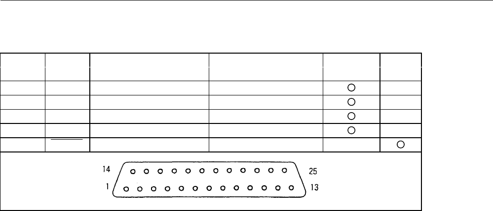
6.2 Connector Pin Assignment
SIGNAL SIGNAL SIGNAL DIRECTION FUNCTION RS232C TTL
PIN NAME HOST-PRINTER
1 FG Frame ground
7 GND Signal ground
3RD →Received data
20 DTR ←Printer BUSY signal
23 RESET →Printer reset signal
Note: 1. Signals for RS-232C are based on EIA RS-232C level.
Applicable connector (D-Sub connector)
Printer : 17LE-13250 (Anphenol equivalent)
Cable : 17JE-23250 (Anphenol equivalent)
6.3 Description of Input / Output Signal
(1) I / O signals
1) RD
Serial input data signal. Data is ignored when framing error, overrun error, or parity error has occurred.
2) DTR
Input command or data while this signal is in ready state. Data input while the signal is BUSY will cause an
overrun error to occur and the data will be ignored. Data can be provided to the input buffer even if the printer is
printing.
Busy state may also occur when power is applied, or during test printing, on-line, or when the printer is reset.
iDP3110 User's Manual
CITIZEN 16
3) RESET
Signal resets the entire printer. (More than 4ms.)
4) FG
Frame ground
5) GND
Common ground for the circuit.
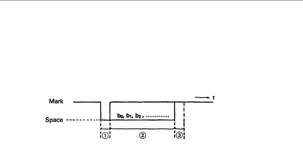
(2) Data configuration
(1) Start bit (1 bit)
(2) Data bit (8 bit)
(3) Stop bit (more than 1)
iDP3110 User's Manual
CITIZEN 17
(3) Electrical characteristics
1) RS-232C circuit
Input (RD)
[PRINTER] [HOST]
MAX 232 equivalent Mark = (-8V) : Stop bit
Space = (+8V) : Start bit
Output (DTR)
MAX 232 equivalent
DTR (-8V) when BUSY
(+8V) when READY
2) TTL circuit
Input (RESET)
7HC14 equivalent Set to LOW when reset
iDP3110 User's Manual
CITIZEN 18
7. DIP SWITCH SETTING
7.1 Serial Interface Type
Switch Functions OFF ON Shipping
NO. Setting
1 Character direction Normal Inverted OFF
selection character character
2 Baud rate selection 9600 BPS 4800 BPS ON
3,4 Not used OFF
7.2 Parallel Interface Type
Switch Function OFF ON Shipping
NO. Setting
1 Character direction Normal Inverted OFF
selection Character character
2Print command CR LF OFF
selection
3, 4 Not used OFF
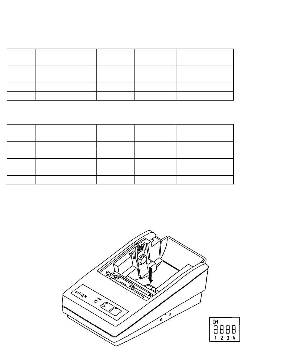
Dip switch position
The Arrow mark in the figure below indicates the location of the dip switch with the printer cover removed.
Power switch OFF the printer before altering the settings.

iDP3110 User's Manual
CITIZEN 19
8. PRINT CONTROL FUNCTION
8.1 Control Command
(1) Print command (CR or LF)
In case of initiate parallel transmission, select code CR (0DH) or LF (0AH) on the DIP switch 2.
If the selected code (CR or LF) is input, the data in the print buffer is printed and line feed is performed.
When the serial interface is used, only the CR code becomes effective.
When graphic (mosaic) printing is performed, line feed is not performed by the print command, and graphic
(mosaic) printing is allowed on the next line.
(2) Input data cancel command (CAN)
By entering the CAN (18H) code, all data entered prior to the entry of the code on a same line is canceled.
(3) Enlarged character printing (SO)
By entering the SO (0EH) code on a specific digit, data entered there-after is output as enlarged characters.
The function is cleared by entering the print code (CR or LF) or DC4 (14H).
The number of printable columns per line for an entire line of enlarged characters are indicated in the table
below.
Model Number of columns
iDP3110-24* 12 columns
iDP3110-40* 20 columns

iDP3110 User's Manual
CITIZEN 20
(4) Power down function
In order to reduce power consumption when printer is waiting for the operation, 2 power down modes triggered
by the codes DC2 and DC3 are incorporated into this product. When the printer receives power down
commands (DC2 or DC3), it switches to the power down mode after all entered data is printed out.
a) DC2 (12H)
Unit switches to power down mode when DC2 code is entered. Operation of the oscillator is not
terminated.
[Power down release]
(a-1) RESET input
By applying “LOW” pulse to the RESET terminal for more than 4ms, the power down mode is
cleared, thereby switching the unit to operational condition approximately 100ms after initialization.
b) DC3 (13H)
Unit switches to power down mode when DC3 code is entered.
Operation of the oscillator is terminated, reducing the power consumption to less than that of the DC2
power down mode.
[Power down release]
(b-1) RESET input
By applying “LOW” pules to the RESET terminal for more than 4ms, the power down mode is
cleared, thereby in HIGH-level switching the unit to operational condition approximately 100ms after
initialization.
(5) Escape control command
By entering ESC (1BH) followed by an ASCII code, the control command indicated below are performed.
Symbol n after the ASCII code indicates an 8 bit binary number. The “+” symbol is used merely as a separator
and is not to be entered.
iDP3110 User's Manual
CITIZEN 21
a) Line spacing setting command (ESC + A + n)
Dot line space setting is determined by entering the code ESC +A + n.
Initial setting is 2 dot line space. The n should be an even number in the range of 0 ≤ n ≤ 255.
Note) If an old number is entered, the dot line is set to “n-1”.
Continuous printing is enabled by specifying n = 0 or 1.
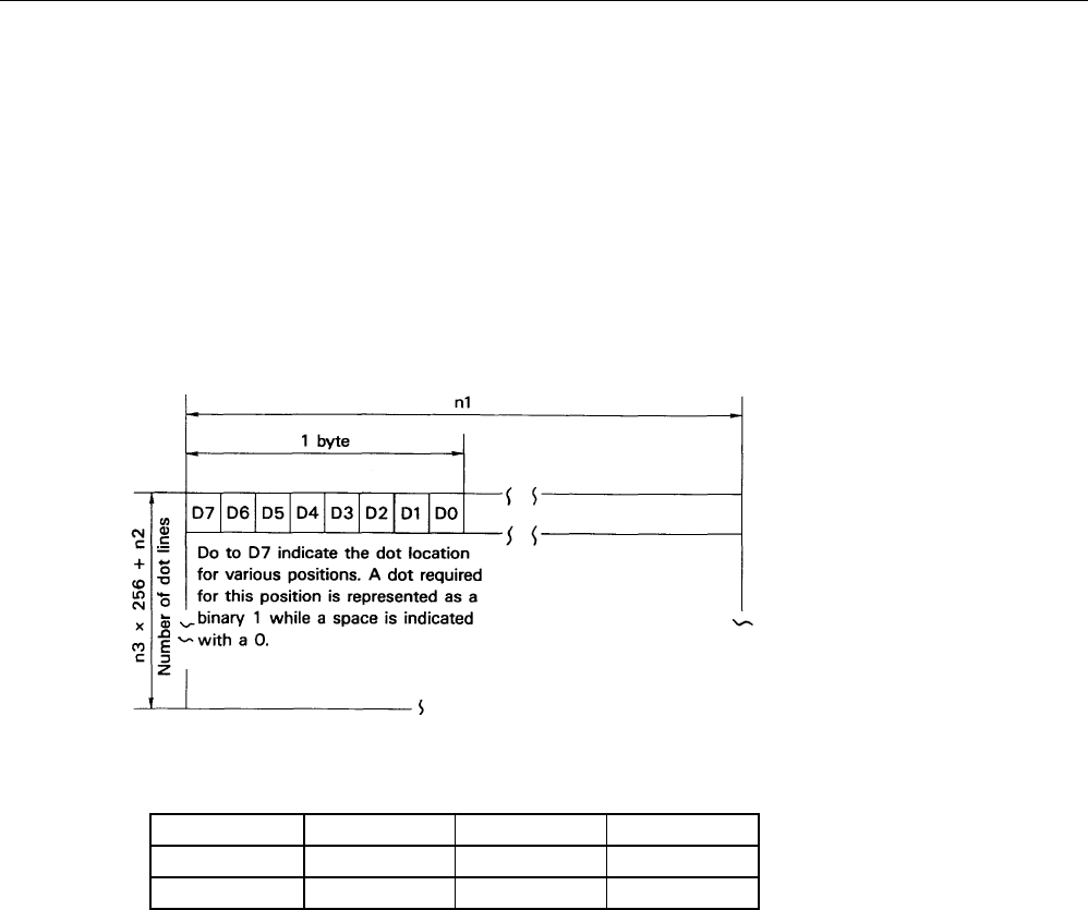
b) Bit image printing (ESC + K + n1 + n2 + n3)
By entering ESC + K + n1 + n2 + n3, print mode is switched from the text mode to bit image mode. n1,
n2, and n3 indicate the transmission volume of the bit image data to follow. That is, n1 indicates the
horizontal byte while n2 and n3 signify the vertical dot lines.
(Relation between the data and printout)
(Range of parameter setting)
MODELn1n2n3
iDP3110-24* 1 to 18 0 to 255 0 to 1
iDP3110-40* 1 to 23 0 to 255 0 to 1
In case a number is beyond the specificable range is specified, and if n2 = n3 = 0 is specified, the bit
image mode is canceled and the printer returns to text mode.

iDP3110 User's Manual
CITIZEN 22
As this printer prints out 4 dot lines as one unit, the lacking data is output as space once the data for 4 dot lines
are read in or the output of data specified in n1, n2 and n3 has finished.
Note 1) If n1 = 23 is specified in iDP3110-40 specification, 4 dots from the topmost dot (MSC DOT)
become invalid. This is due to the fact that the output position for a single line consists of 180
dots.
Note 2) Although the printer returns to text mode when bit image mode printout is completed, line
spacing is set to 0 to enable further output in the bit image mode. Line feed is required in order
to commence text mode output.
For bit image printing, inverted printing is not performed but normal printing, even if the DIP
switch 1 is set to “ON”.
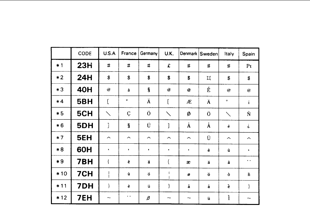
c) International character setting (ESC + R + n)
By entering the code ESC + R + n, characters input hereafter are set to the characters for the following
countries.
Then n value and country setting is as indicated in the table below.
n Country n Country
0 America 5 Sweden
1France 6 Italy
2Germany 7 Spain
3 England 8 Japan
4Denmark
n other than that specified becomes invalid and the setting prior to the invalid specification is employed.
When the printer is turned on or RESET, the country is set to n = 0 (America).

iDP3110 User's Manual
CITIZEN 23
d) Character registration (ESC + & + A1 + A2)
Individual patterns can be registered by entering the code ESC + & + A1 + A2, then entering the pattern
data.
A maximum of 8 characters can be registered, and any address in the range of 20H to FFH can be used for
the registration. However, if a new pattern is registered in an address already in use, existing data is cleared
and the newly entered data becomes valid. If more than 8 characters are registered, all existing character
registration is cleared.
[Address setting]
Specified address is matched to the character code and can be accessed likewise to the stored fixed
character record.
If a fixed character is defined in the specified address, the fixed character becomes invalid.
A1 signifies the starting address for the registration and A2 is the ending address.
[Method of data transmission]
d-1) Single character registration
Select the address to be defined (character code) from among 20H to FFH and designate is as A1.
When registering a single character, starting and ending addresses match each other. Tat is, A1 = A2.
<Example> A 6 × 8 dot matrix full dot pattern is to be registered in address 41H (code for the fixed
character “A”).
(Numerals are hexadecimal.)
1B • 26 • 41• 41 • FF • FF • FF • FF • FF • FF
↑ ↑ ↑ ↑
ESC & A1 A2 Pattern data (6 bytes)
In the successive controls, a 6 × 8 dot matrix full dot is output whenever the character code 41H is
specified. (Character “A” cannot be accessed.)
iDP3110 User's Manual
CITIZEN 24
d-2) Multiple character registration
By repeating the single character registration, a maximum of 8 characters can be registered.
When defining multiple characters in a successive address (character code), register pattern data for a
maximum of 8 characters by designation A1 as the starting address and A2 as the ending address.
Note) A1<A2, A2-A1≤7
[Pattern data configuration]
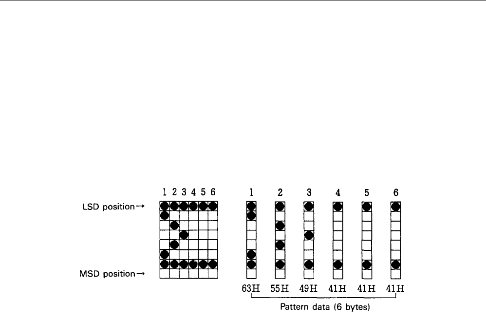
d-3) In case of iDP3110-24* (24 columns) specification
Pattern data to be registered must consist of 6 bytes per character. That is, pattern data configured by
a 6 × 8 dot matrix is broken up into 6 vertically positioned units each of which is represented by 1
byte of data. All together, 6 bytes of data are transmitted.
<Example> When transmitting the following data,
iDP3110 User's Manual
CITIZEN 25
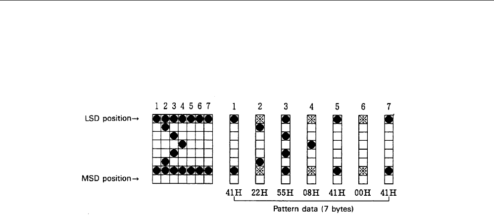
d-4) In case of iDP3110-40* (40 columns) specification
Pattern data to be registered must consist of 7 bytes per character.
That is, pattern data configured by a 7 × 8 dot matrix is broken up into 7 vertically positioned units
each of which is represented by 1 byte of data. All together, 7 bytes of data are transmitted.
<Example> When transmitting the following data,
As the model utilizes the half-dot printing method, it is not capable of positioning successive dots in
the printing direction (between print). Therefore, pattern specification in the position “*” to the right
of the position “•” in the diagram above will not be registered as pattern data.
e) Continuous paper feed command (ES + B + n)
By entering the code ESC + B + n, continuous paper feed operation is carried out for n dot lines.
The n should be an even number in the range of 4 ≤ n ≤ 255. If an odd number is entered, the dot line is set
to “n-1”. The command is canceled if a number exceeding this range is specified.
If printout data is stored within the input buffer when the command is entered, the printer commences with
the printout. However, the print line (10 dot line) will be included in the line feed value “n”. Therefore, if
4 ≤ n ≤ 9 is specified, line space shall be set as “0”.
iDP3110 User's Manual
CITIZEN 26
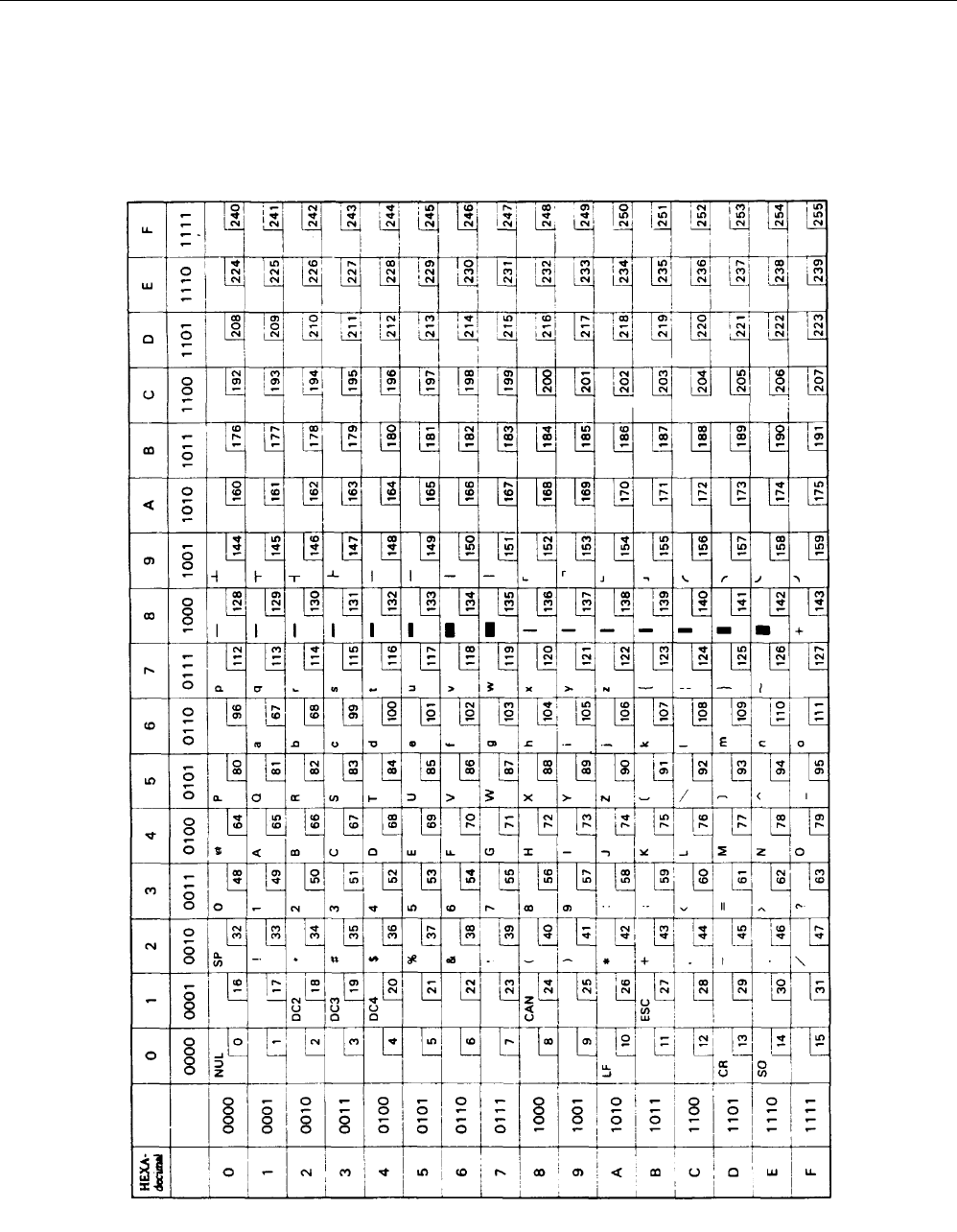
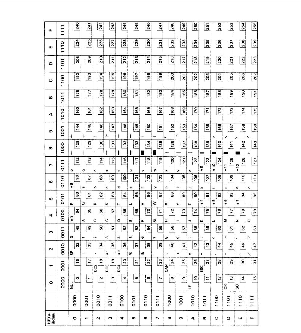
9. CHARACTER SET
9.1 Character code
(In the following Table *1-*12 are the characters of the next page by a command, ECS + R + n.)
iDP3110 User's Manual
CITIZEN 27
iDP3110 User's Manual
CITIZEN 28
Individual Country
Character Codes
iDP3110 User's Manual
CITIZEN 29
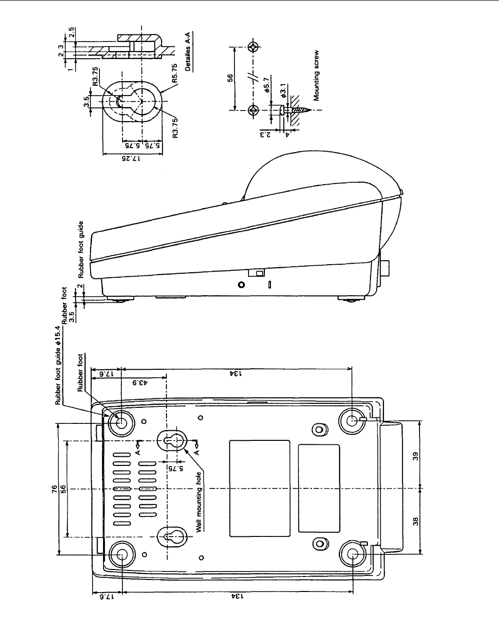
10. EXTERNAL DIMENSIONS
iDP3110 User's Manual
CITIZEN 30

Information Systems Division CBM Bldg., 5-68-10, Nakano, Nakano-ku, Tokyo 164-0001, Japan
Head Office Tel: (+81-3) 5345-7540 Fax: (+81-3) 5345-7541
20-990914-5000-0036-005.25 Printed in Japan
