Citizen CL S700 Technical Manual User To The 1e0342dc 8bdd 4c71 8454 B09fe8ca3f92
User Manual: Citizen CL-S700 to the manual
Open the PDF directly: View PDF ![]() .
.
Page Count: 257 [warning: Documents this large are best viewed by clicking the View PDF Link!]
- Cover
- Contents (Chapters)
- CHAPTER 1 SPECIFICATIONS
- CHAPTER 2 OPERATING PRINCIPLES
- 2-1. Operation of Each Mechanism
- 2-1-1. Locations of Main Electrical Parts
- 2-1-2. Media Feed Mechanism
- 2-1-3. Label/Tag Position Detection Mechanism
- 2-1-4. Top Cover Open Detection Mechanism
- 2-1-5. Print Head Up/Down Detection Mechanism
- 2-1-6. Head Balance Adjustment Mechanism
- 2-1-7. Media Thickness Adjustment Mechanism
- 2-1-8. Rewinder Cover Open Detection Mechanism (CL-S700R only)
- 2-1-9. Rewinding Mechanism (CL-S700R only)
- 2-2. Operation of Control Parts
- 2-3. Operation Panel
- 2-4. Interface
- 2-1. Operation of Each Mechanism
- CHAPTER 3 DISASSEMBLY AND MAINTENANCE
- 3-1. Maintenance Precautions
- 3-2. Cleaning
- 3-3. Lubrication/Adhesive Agent
- 3-4. Maintenance Tools List
- 3-5. Disassembly, Reassembly and Lubrication
- 3-5-1. Unit, Head
- 3-5-2. Unit, Roller Platen and Gear, One-way
- 3-5-3. SA, Ope-pane PCB and SA, Cover Open Sens
- 3-5-4. Unit, Power Supply
- 3-5-5. SA, Main PCB and Unit, Centro PCB
- 3-5-6. SA, Fan
- 3-5-7. SA1, Top Cover
- 3-5-8. Unit, Mechanism
- 3-5-9. Each Unit on the “Unit, Mechanism”
- 3-5-10. SA, Base Guide Open
- 3-5-11. Unit, Sensor Adjust
- 3-5-12. Unit, Frame Ribbon L
- 3-5-13. Disassembling the “SA, Front Tension Arm”
- 3-5-14. Disassembling the “SA, Frame Ribbon R”
- 3-5-15. Disassembling the “Unit, Frame Rear”
- 3-5-16. Disassembling the “Unit, Frame U”
- 3-5-17. Disassembling the “Unit, Frame”
- 3-5-18. Disassembling the Rewinder Part (CL-S700R Only)
- (1) Separating the Rewinder part
- (2) Removing the Rewinder Mechanism block
- (3) Removing the “Door, Rewinder” and “SA1, Peeler”
- (4) Removing the “SA, Peel Sensor”/Friction Roller/Idle Rewinder Roller
- (5) Removing the “SA, Rewinder Motor”
- (6) Removing the “SA, Interlock SW”
- (7) Removing Rollers
- (8) Removing “SA, Rewinder PCB”
- (9) Notes on assembling the springs
- 3-6. Adjustments
- CHAPTER 4 TROUBLESHOOTING
- 4-1. Error Message and Corrective Actions
- 4-2. Troubleshooting
- CHAPTER 5 PARTS LISTS
- Chapter 5 Parts Lists
- Recommended Spare Parts List
- Drawing No. 1 Parts List & Location for General Assembly
- Drawing No. 2 Parts List & Location for Unit, Mechanism
- Drawing No. 3 Parts List & Location for Unit, Frame U
- Drawing No. 4 Parts List & Location for SA, Front Tension Arm
- Drawing No. 5 Parts List & Location for Unit, Frame Rear
- Drawing No. 6 Parts List & Location for SA, Frame Ribbon R
- Drawing No. 7 Parts List & Location for SA, Base Guide Open
- Drawing No. 8 Parts List & Location for Unit, Sensor Adjust
- Drawing No. 9 Parts List & Location for Unit, Frame
- Drawing No. 10 Parts List & Location for Unit, Top Cover
- Drawing No. 11 Parts List & Location for SA, Ope-pane
- Drawing No. 12 Parts List & Location for SA, Front Center
- Drawing No. 13 Parts List & Location for SA, Front Right
- Drawing No. 14 Parts List & Location for Unit, PCB
- Drawing No. - Parts List & Location for Accessories
- Chapter 5 Parts Lists
- Chapter 5 Parts Lists
- CHAPTER 6 CIRCUIT DIAGRAMS
- Inter Connection (Main PCB 1/15) (CL-S700/CL-S703)
- Inter Connection (Main PCB 1/15) (CL-S700R)
- Circuit Diagram (Main PCB 2/15) [CPU (1)]
- Circuit Diagram (Main PCB 3/15) [CPU (2)/DAC]
- Circuit Diagram (Main PCB 4/15) [ROM]
- Circuit Diagram (Main PCB 5/15) [RAM]
- Circuit Diagram (Main PCB 6/15) [Custom IC]
- Circuit Diagram (Main PCB 7/15) [Head Control]
- Circuit Diagram (Main PCB 8/15) [PF Motor Control]
- Circuit Diagram (Main PCB 9/15) [Sensor]
- Circuit Diagram (Main PCB 10/15) [Power/Buzzer/Fan]
- Circuit Diagram (Main PCB 11/15) [RFID/Ope-Pane]
- Circuit Diagram (Main PCB 12/15) [Cutter/Rewinder]
- Circuit Diagram (Main PCB 13/15) [Centronics I/F]
- Circuit Diagram (Main PCB 14/15) [Serial I/F]
- Circuit Diagram (Main PCB 15/15) [USB I/F]
- Circuit Diagram (Power Supply PCB (100/240V))
- Circuit Diagram (Ope-pane PCB)
- Circuit Diagram (Centronics PCB)
- Circuit Diagram (Connect PCB) (CL-S700/CL-S703)
- Circuit Diagram (Rewinder PCB) (CL-S700R)
- APPENDICES
Technical Manual
CL-S700/CL-S703/CL-S700R
Thermal Transfer Barcode & Label Printer
JN74928-10F
1.02E-1012

CL-S700/CL-S703/CL-S700R ii
Copyright © 2010 by CITIZEN SYSTEMS JAPAN CO., LTD.

CL-S700/CL-S703/CL-S700R iv
Safety Precautions
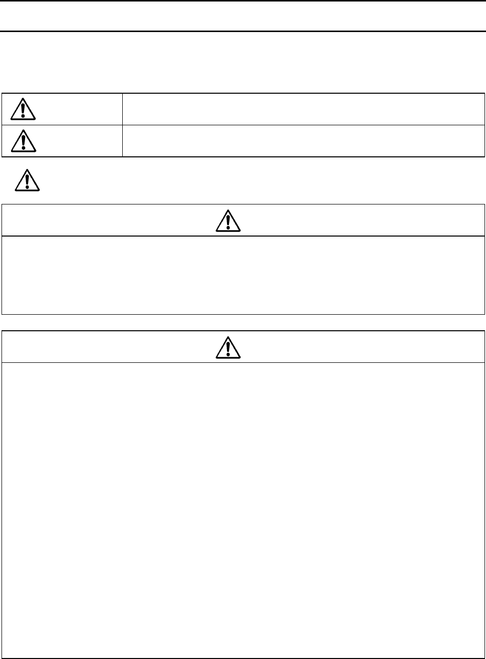
To prevent personal injury or property damage, the following shall be strictly observed.
The degree of possible injury and damage due to incorrect use/maintenance or improperly
following instructions is described below.
Indicates a situation which, if not observed and handled properly, could
result in death or serious injury.
Indicates a situation which, if not observed and handled properly, could
result in injury or property damage.
: This is a mark to call attention to the reader.
- Before starting disassembly/reassembly or mechanical adjustment, be sure to
disconnect the power cord from the power source.
- Do not replace a fuse with the power switch turned on.
- When replacing a fuse, use the same rating and type since it is provided to prevent
fire and damage to the “Unit, Power Supply”.
- DO NOT adjust VR1, VR2, VR3 and VR4 on the “SA, Main PCB”. (Leave them at the
factory setting condition.) If it is turned, media sensor sensitivity is changed and the
media detection will not be correctly made.
- Do not disassemble/reassemble or adjust the machine, if it functions properly.
Particularly, do not loosen screws on any component, unless necessary.
- After completing an inspection and before turning on the power, be sure to check that
there is no abnormality.
- Never try to print without media.
- Check that the media is properly set.
- Do not lay anything on the cover or lean against it during maintenance or while the
printer is in operation.
- During maintenance, be careful not to leave parts or screws unattached or loose
inside the printer.
- When handling a printed circuit board, do not use gloves, etc., which can easily
cause static electricity. Since ICs, such as CPU, RAM and ROM, might be destroyed
by static electricity, do not touch lead wires or windows unnecessarily.
- Do not put the printed circuit boards directly on the printer or on the floor.
- When disassembling or reassembling, check wires for any damage and do not pinch
or damage them. Also, run wires as they were.
Warning
Caution
Warning
Caution

Chapter 1 Specifications
CL-S700/CL-S703/CL-S700R
CHAPTER 1
SPECIFICATIONS
Chapter 1 Specifications
CL-S700/CL-S703/CL-S700R 1-2
Chapter 1 Specifications
Table of Contents
1-1. General Specifications.................................................................................................... 1-3
1-2. Printable Area .................................................................................................................1-9
1-3. Printing Position Accuracy .............................................................................................. 1-10
1-4. Adjustable Sensors/Front Fixed Sensor ......................................................................... 1-11
Chapter 1 Specifications
1-1. General Specifications
1-3 CL-S700/CL-S703/CL-S700R
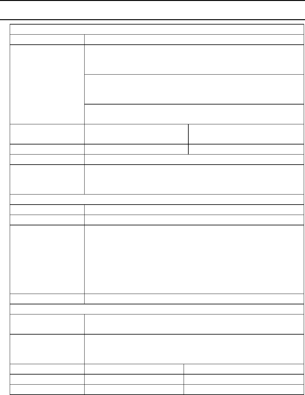
1-1. General Specifications
Printing
Printing method Thermal transfer/Direct thermal
Main scanning line density:
203 dots/inch (8 dots/mm) (CL-S700/CL-S700R)
300 dots/inch (11.8 dots/mm) (CL-S703)
Sub-scanning line density:
203 dots/inch (8 dots/mm) (CL-S700/CL-S700R)
300 dots/inch (11.8 dots/mm) (CL-S703)
Resolution
Head 864 dots (printable dots: 832 dots) (CL-S700/CL-S700R)
Head 1275 dots (printable dots: 1240 dots) (CL-S703)
Max. print width 104 mm (CL-S700/CL-S700R)
105 mm (CL-S703)
4.1 inch (CL-S700/CL-S700R)
4.1 inch (CL-S703)
Max. print length 812.8 mm 32 inch
Print density Print density is adjustable with software
Printing speed setting 2 - 10 inches per second (CL-S700/CL-S700R)
2 - 8 inches per second (CL-S703)
*2-7 inches per second (CL-S700/CL-S703 with optional peeler)
Print mode
Batch mode Normal printing (single or multiple sheets)
Tear off mode Feeds back media to the tear-off position after printing is completed.
Cut mode *1 Prints while cutting at designated sheet units.
The following two kinds of cut mode operations are done.
• Back feed
• Cut through
(Cut through refers to stopping part-way through printing the ‘next
label’ to make the cut. After cutting, printing restarts but there is a
chance of a small gap or mark at the temporary stop position.)
Peel mode*2 Peels labels from the liners after printing them.
Media
Types of media Roll, fanfold
(continuous media, die-cuts, continuous tags, paper or tickets)
Recommended media Thermal transfer: label media (RPR-W Ricoh)
Direct thermal media: label media (150LA-1 Ricoh),
tag media (TB2E0V, Mitsubishi Paper)
Max. media width 118.0 mm 4.65"
Min. media width 25.4 mm 1.00"
Min. label width 7.62 mm 0.30"
*1,*2: Options can be separately purchased.
Chapter 1 Specifications
1-1. General Specifications
CL-S700/CL-S703/CL-S700R 1-4
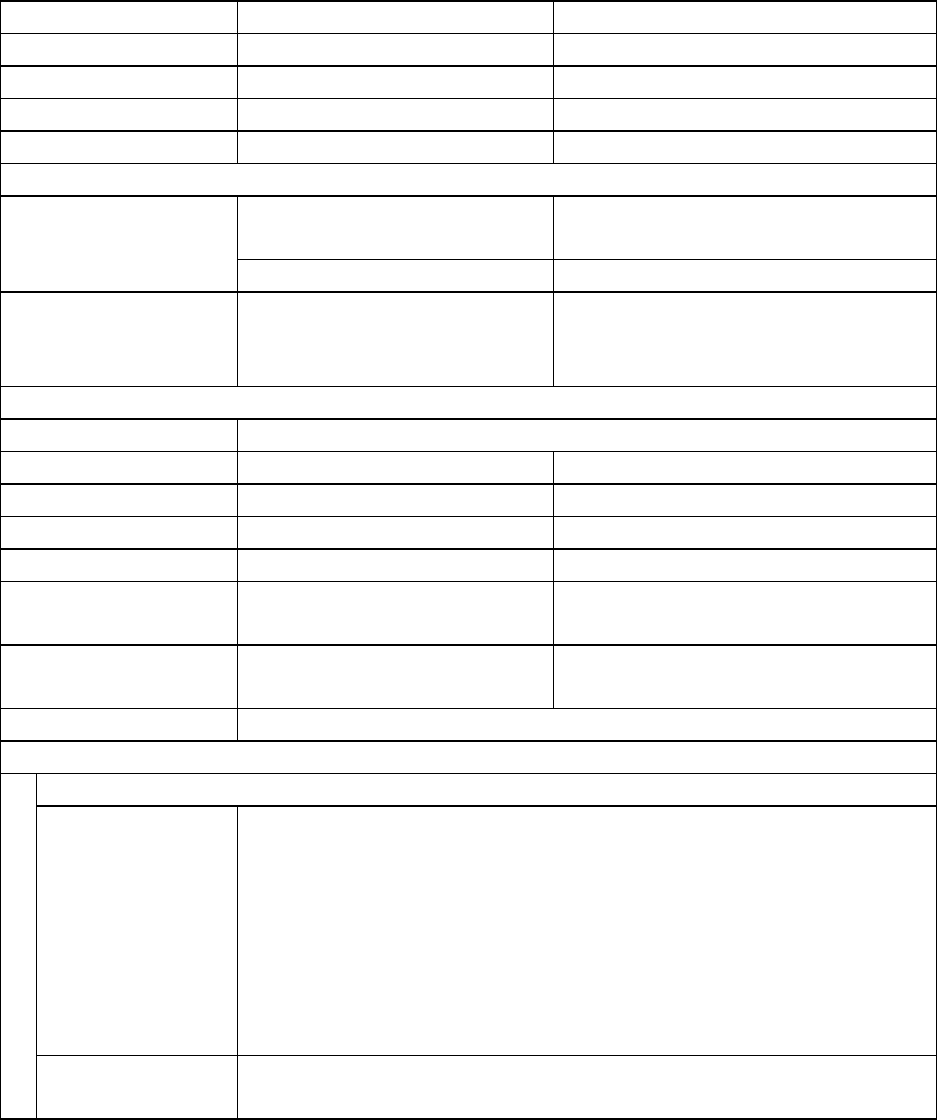
Min. label pitch*3 6.35 mm 0.25"
Max. media thickness 0.254 mm 0.01"
Max. media length 812.8 mm 32"
Min. media length 6.35 mm 0.25"
Min. media thickness 0.0635 mm 0.0025"
Media (continued)
Max. outside diameter:
203 mm
8"
On-board roll media
diameter
Media core: 38 to 76 mm 1.5 to 3"
Rewinding roll media
diameter (CL-S700R
only)
Media core: 26, 40, or 45 mm 1.02, 1.57, or 1.77”
Ribbon
Recommended ribbon B110A Ricoh
Max. ribbon width 114.0 mm 4.50"
Min. ribbon width 25.4 mm 1.00"
Min. ribbon length 450.0 m 1,476 ft
Max. roll diameter 86.5 mm 3.40"
Inner diameter of the
paper core
25.4 ± 0.25 mm 1.00 ± 0.01"
Ribbon end tape
length
Max. 80.0 mm 3.15"
Ribbon end detection Ribbon out is detected by the ribbon sensor.
Bar code
For Datamax® emulation*4
One-dimension • Code 3 of 9 • UPC-A • UPC-E • EAN-13 (JAN-13)
• EAN-8 (JAN-8) • Interleaved 2 of 5 • Code 128
• HIBC (Modulus 43-used code 3 of 9) • Codabar (NW-7)
• Int 2 of 5 (Modulus 10-used Interleaved 2 of 5) • Plessey
• Case Code • UPC 2DIG ADD • UPC 5DIG ADD
• Code 93 • Telepen • ZIP • UCC/EAN 128
• UCC/EAN128 (for K-MART)
• UCC/EAN128 Random Weight • FIM
Two-dimension • UPS Maxi Code • PDF-417 • Data Matrix • QR Code • Aztec
• RSS
*3: When a media pitch of less than 1" is used, activate the "Small Label Printing" setting in
the "Printing Setting".
*4: Datamax® is a registered trademark of Datamax Bar Code Products Corporation.
Chapter 1 Specifications
1-1. General Specifications
1-5 CL-S700/CL-S703/CL-S700R
Bar code (continued)
For Zebra® emulation*5
One-dimension • Code 11 • Interleaved 2 of 5 • Code 39 • EAN-8 • UPC-E
• Code 93 • Code 128 • EAN-13 • Industrial 2 of 5
• Standard 2 of 5 • ANSI CODABAR • LOGMARS • MSI • Plessey
• UPC/EAN Extensions • UPC-A • POSTNET • Planet
Two-dimension • Code 49 • PDF-417 • CODA BLOCK • UPS Maxi Code
• Micro PDF-417 • Data Matrix • QR Code • R SS • TLC39
Font
For Datamax® emulation*4
1. Seven kinds of fixed pitch font
Overseas, English fonts and European fonts
2. OCR fonts
OCR-A*6, OCR-B*6
3. Proportional fonts
CG TriumvirateTM smooth font
CG TriumvirateTM Bold smooth font
(6, 8, 10, 12, 14, 18, 24, 30, 36, 48 points) (CL-S700/CL-S700R)
(4, 5, 6, 8, 10, 12, 14, 18, 24, 30, 36, 48 points) (CL-S703)
• Character set: Conforms with code page 850 standards
4. TrueTypeTM rasterizer *7
For Zebra® emulation*5
1. Five kinds of fixed pitch font
Overseas, English fonts and European fonts
2. OCR fonts
OCR-A, OCR-B
3. Proportional font
CG TriumvirateTM Condensed Bold
4. True type™ rasterizer*7
*5: Zebra® is a registered trade mark of ZIH corp.
*6: The OCR font may have a low recognition rate according to the reader.
*7: It is equipped with UFSTTM and TrueTypeTM rasterizer that are licensed from Monotype
Imaging, Inc.
TrueTypeTM is a trademark of Apple Computer.
UFSTTM and CG TriumvirateTM are trademarks of Monotype Imaging, Inc.

Chapter 1 Specifications
1-1. General Specifications
CL-S700/CL-S703/CL-S700R 1-6
Symbol set
PC866U Ukraina, PC Cyrillic, ISO 60 Danish/Norwegian, DeskTop,
ISO 8859/1 Latin 1, ISO 8859/2 Latin 2, ISO 8859/9 Latin 5, ISO
8859/10 Latin 6, ISO 8859/7 Latin/Greek, ISO 8859/15 Latin 9, ISO
8859/5 Latin/Cyrillic, ISO 69: French, ISO 21: German, ISO 15:
Italian, Legal, Math-8, Macintosh, Math, PC-858 Multilingual,
Microsoft Publishing, PC-8, Code Page 437, PC-8 D/N, Code Page
437N, PC-852 Latin 2, PC-851 Latin/Greek, PC-862 Latin/Hebrew, Pi
Font, PC-850 Multilingual, PC-864 Latin/Arabic, PC-8 TK, Code Page
437T, PC-1004, PC-775 Baltic, Non-UGL, Generic Pi Font, Roman-8,
Roman-9, ISO 17: Spanish, ISO 11: Swedish, Symbol, PS Text, ISO
4: United Kingdom, ISO 6: ASCII, Ventura International, Ventura
Math, Ventura US, Windows 3.1 Latin 1, Wingdings, Windows 3.1
Latin 2, Windows 3.1 Baltic (Latv, Lith), Windows 3.0 Latin 1,
Windows Latin/Cyrillic, Windows 3.1 Latin 5
Control language
Conforms to Datamax® programming language*4 and Zebra®
programming language*5
Outline of electronic devices
CPU 32-bit RISC CPU
ROM Standard equipment: FLASH ROM 4M bytes (User area: 1M byte)
RAM Standard equipment: SDRAM 16M bytes (User area: 1M byte)
RAM (for Zebra® L) Standard equipment: SDRAM 16MBytes (User area: 4M byte)
Media detection sensors
Transparent sensor Detects media gap between labels, notches on tags, and media out
Reflective sensor Detects reflective mark on back of media and media out
Label peeling sensor *1
Communication interfaces
Parallel*8 IEEE1284 (Compatible, Nibble, ECP mode)
Serial 2400 4800 9600 19200 38400 57600 115200 bps
USB FULL Speed USB1.1
Communication interface options
Network Wired Ethernet (10-BASE-T/ 100-BASE-TX) or Wireless LAN
*8: This interface is Non-L. P. S. (Limited Power Source).

Chapter 1 Specifications
1-1. General Specifications
1-7 CL-S700/CL-S703/CL-S700R
Indications and switches
LCD 128 X 64 dots, STN graphic type
LED POWER, ERROR
Buzzer Alarms, errors, etc.
Operating panel keys PAUSE, FEED, STOP, MENU
Head-up detection
sensor
Detects head open.
Power switch Turns power on and off.
Acoustic noise 55 dB (by EN ISO7779)
Power supply (standards)
100-240V (-10%+6%), 3.5-1.5A, 50/60Hz
U.S.A./Canada: UL60950-1, CSA No.60950-1, FCC Part 15 Subpart
B (Class A)
Europe: EN 60950-1, EN 55022 (ClassA), EN 55024, EN 61000-3-2,
EN 61000-3-3
Power consumption (max. value)
U.S.A./Canada
(120V
130W (operating at 12.5% printing duty), 11W (standby) (CL-S700)
95W (operating at 12.5% printing duty), 12W (standby) (CL-S703)
140W (operating at 12.5% printing duty), 12W (standby) (CL-S700R)
Europe
(230V)
120W (operating at 12.5% printing duty), 11W (standby) (CL-S700)
85W (operating at 12.5% printing duty), 11W (standby) (CL-S703)
130W (operating at 12.5% printing duty), 12W (standby) (CL-S700R)
Chapter 1 Specifications
1-1. General Specifications
CL-S700/CL-S703/CL-S700R 1-8
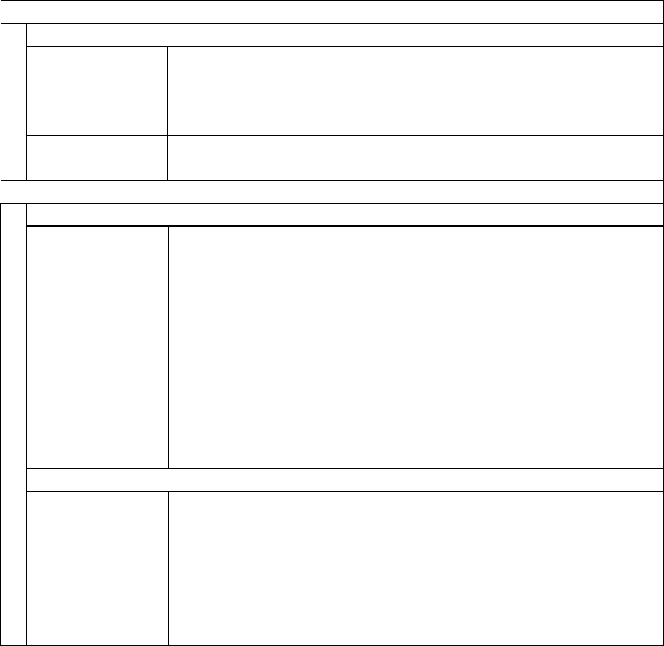
Others
Environment Operating temperature conditions:
Operating temp. 0 to 40°C, humidity 30 to 80%, condensation free
(Conditions: ventilation, and natural convection)
Storage temperature conditions
Temp. -20 to 60°C, humidity 5 to 85%
(Conditions: ventilation, and natural convection)
[Conditions assuring operation and printing] [Storage assurance condition]
External dimensions
(CL-S700/CL-S703)
Approx. 255 (W) X 490 (D) X 265 (H) mm
10 (W) X 19.3 (D) X 10.4 (H)"
External dimensions
(CL-S700R)
Approx. 254 (W) X 480 (D) X 375 (H) mm
10.2 (W) X 19.2 (D) X 15 (H)"
Weight Approx. 13.3 kg (29.3 lb.) (CL-S700/CL-S703)
Approx. 17.6 kg (38.7 lb.) (CL-S700R)
Accessories Test label media, Test ribbon, CD-ROM (User’s Manual), Quick start
guide, Head cleaner, Power cord, Media holder bar and Media holder
guide, Ribbon holder, Paper core
Option Auto-cutter unit, Peeler unit, Ethernet interface and Rewind kit
-20 60
5
85
Humidity %
Temperature °C
Operating assurance temperature
Printing assurance temperature
0 535 40
30
40
80
Humidit
y
%
Temperature °C
Storage assurance
temperature
Chapter 1 Specifications
1-2. Printable Area
1-9 CL-S700/CL-S703/CL-S700R
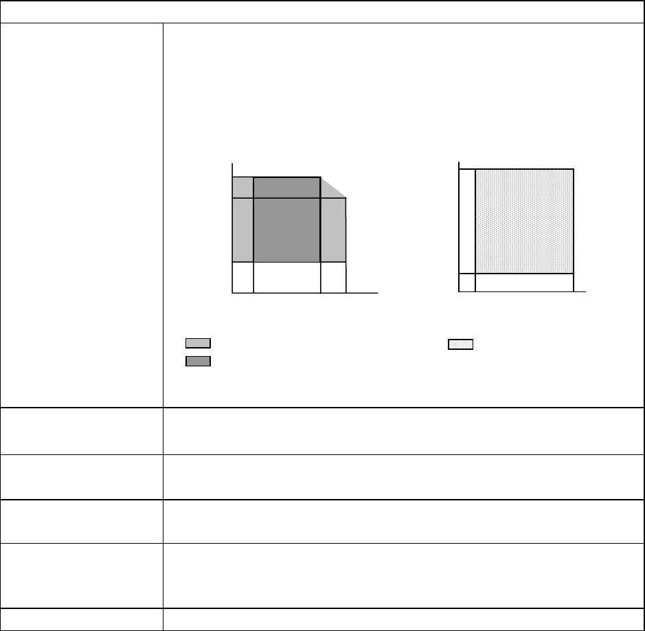
1-2. Printable Area
The printable area of the printer is as follows:
When media is set to the printer, it must be aligned with the media guide at the left of the printing
mechanism. Though the available maximum media width is 118 mm (4.65"), there are unprintable
areas on both sides: 2.5 mm (0.10") width is on the left side and 11.5 mm (0.45") (for CL-S700/
CL-S700R)/10.5 mm (0.41”) (for CL-S703) width on the right side.
The left side unprintable area applies for any size media.
MODEL H R
CL-S700/CL-S700R 104.0 mm
(4.1”)
11.5 mm
(0.45”)
CL-S703 105.0 mm
(4.1”)
10.5 mm
(0.41”)
Maximum media width: 118 mm (4.65")
H R
Reference end
Unprintable area
Printable area
Media guide
Direction of media feed
2.5 mm (0.10")
Chapter 1 Specifications
1-3. Printing Position Accuracy
CL-S700/CL-S703/CL-S700R 1-10
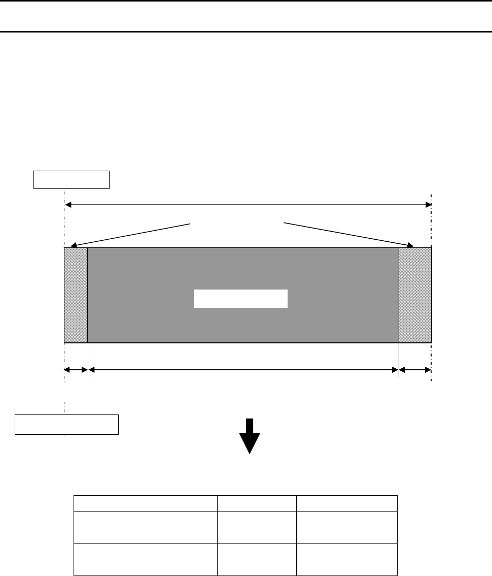
1-3. Printing Position Accuracy
By default, the printing start position is 2.5 mm (0.10") from the left end of the media and 1 mm
(0.04") backward the leading edge of the label, U-shaped notch, or black mark.
2.5 mm (0.10") is the necessary value to avoid printing in the unprintable area as mentioned in 1-2
"Printable Area".
The printing start position will deviate from the ideal position as follows:
*1: Actual printing start position. May deviates from the ideal one in the indicated range.
*2: Deviation of vertical positioning when printing position is set to 0.
*3: Deviation of horizontal positioning when printing position is set to 0.
*4: Deviation of vertical printing position when 100 mm is specified from the printing start
position.
1
±
2 mm*
2
(0.04 ± 0.08")
Reference edge
(Paper guide)
Printable area
Direction of media feed
Ideal printing start position
Actual printing start position*
1
2.5 ± 1 mm*
3
(0.10 ± 0.04")
100
±
2 mm*
4
(39.4 ± 0.08")
Maximum media width: 118 mm (4.65")
Unprintable area
2.5 mm
(0.10")
1 mm (0.04")
Unprintable area
Chapter 1 Specifications
1-4. Adjustable Sensors/Front Fixed Sensor
1-11 CL-S700/CL-S703/CL-S700R
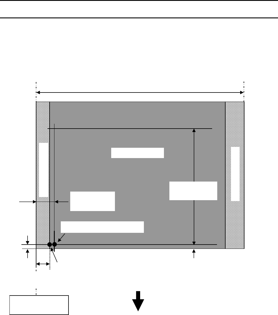
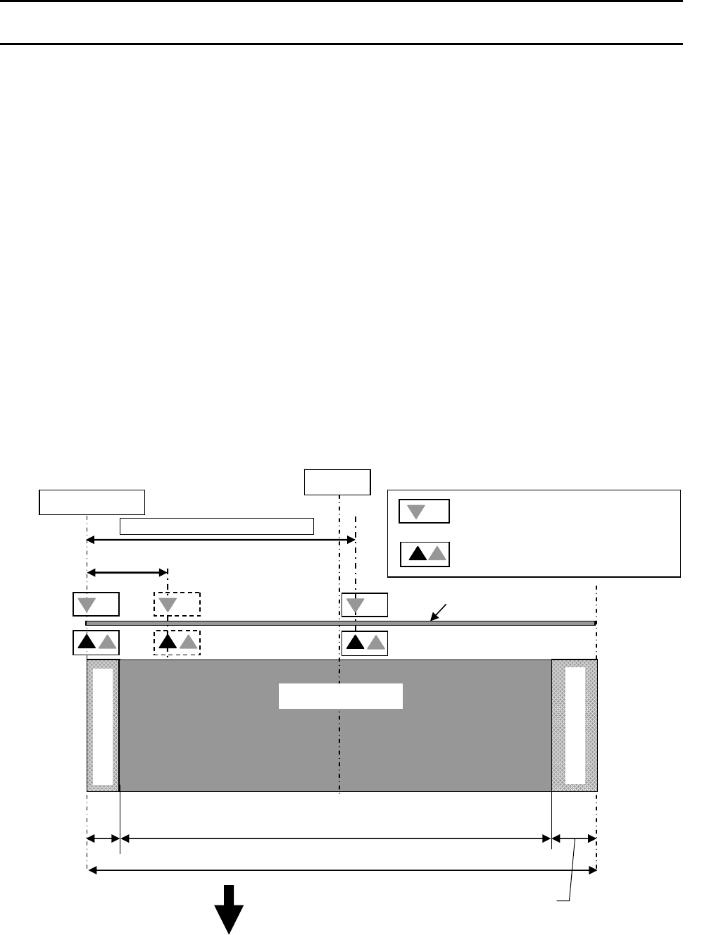
1-4. Adjustable Sensors/Front Fixed Sensor
There are two types of media sensors (adjustable sensor located on the rear side of the printer and
front fixed sensor located on the front left) that detect a label or tag position. They are selectable
with the Sensor Select menu (“Rear Adj sensor” for adjustable sensor and “Front Fixed Sen” for
front fixed sensor). By default, the adjustable sensor is selected and it covers wide range of media
width. The front fixed sensor is suitable for printing narrower width media and, since it is located
near the thermal head, more accurate detection of label or tag position will be expected.
Adjustable sensor:
Adjustable sensor consists of two media sensors; the upper sensor (transparent sensor) and the
bottom sensor (reflective sensor). The upper sensor and bottom sensor are used to detect the
labels on the liner or the U-shaped notches of tag. While, the bottom sensor is used to detect the
black marks on tag. Both sensors are used to detect media end.
By turning the adjustable sensor position knob, both transparent and reflective sensors move right
and left simultaneously. As you turn the adjustable sensor position knob, the yellow mark that is
located in front of the scale moves along the scale.
The factory-set position of the sensors is 6.5mm (0.2559") from the media guide. In this position,
the T mark is printed on the scale and this position is the same position as the front fixed sensor.
For details about the adjustable sensors, refer to “2-1-3.Label/Tag Position Detection Mechanism".
Maximum media width: 118 mm (4.65")
104.0 mm (4.1") (CL-S700/CL-S700R)
105.0 mm (4.1”) (CL-S703)
11.5 mm
(0.45")
Media guide
Direction of media feed
2.5 mm
(
0.10"
)
Unprintable area
Unprintable area
0 to 59 mm (0 to 2.32")
Moveable range of sensors
Center
Printable area
Media
T: Upper sensor (LED)
S: Lower sensor (Phototransistor)
S: Lower sensor (LED)
6.5 mm (0.2559")
Factory-set position
11.5 mm (0.45”) (CL-S700/CL-S700R)
10.5 mm (0.41”) (CL-S703)
Chapter 1 Specifications
1-4. Adjustable Sensors/Front Fixed Sensor
CL-S700/CL-S703/CL-S700R 1-12
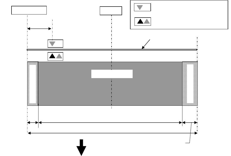
Front fixed sensor:
It is basically the same as the adjustable sensor except that the front fixed sensor is not adjustable.
Maximum media width: 118 mm (4.65")
11.5 mm
(0.45")
Media guide
Direction of media feed
2.5 mm
(
0.10"
)
Unprintable area
Unprintable area
Center
Printable area
Media
6.5 mm (0.2559")
T: Upper sensor (LED)
S: Lower sensor (Phototransistor)
S: Lower sensor (LED)
104.0 mm (4.1") (CL-S700/CL-S700R)
105.0 mm (4.1”) (CL-S703)
11.5 mm (0.45”) (CL-S700/CL-S700R)
10.5 mm (0.41”) (CL-S703)

Chapter 2 Operating Principles
CL-S700/CL-S703/CL-S700R
CHAPTER 2
OPERATING PRINCIPLES
Chapter 2 Operating Principles
CL-S700/CL-S703/CL-S700R 2-2
Chapter 2 Operating Principles
Table of Contents
2-1. Operation of Each Mechanism ....................................................................................... 2-4
2-1-1. Locations of Main Electrical Parts ...................................................................... 2-4
(1) CL-S700/CL-S703/CL-S700 (Printer Part) ................................................2-4
(2) CL-S700 (Rewinder Part) .......................................................................... 2-6
2-1-2. Media Feed Mechanism ..................................................................................... 2-7
2-1-3. Label/Tag Position Detection Mechanism ..........................................................2-8
2-1-4. Top Cover Open Detection Mechanism.............................................................. 2-9
2-1-5. Print Head Up/Down Detection Mechanism ....................................................... 2-10
2-1-6. Head Balance Adjustment Mechanism...............................................................2-11
2-1-7. Media Thickness Adjustment Mechanism .......................................................... 2-12
2-1-8. Rewinder Cover Open Detection Mechanism (CL-S700R only)......................... 2-13
2-1-9. Rewinding Mechanism (CL-S700R only) ........................................................... 2-14
2-2. Operation of Control Parts .............................................................................................. 2-15
2-2-1. Configuration of Printer ......................................................................................2-15
(1) AC Inlet & Power Switch/Filter & Power Supply section............................ 2-16
(2) Main PCB .................................................................................................. 2-16
(3) Operation panel ......................................................................................... 2-17
(4) Thermal print head .................................................................................... 2-17
(5) Sensors ..................................................................................................... 2-17
(6) Motors........................................................................................................ 2-17
(7) Parallel I/F (IEEE1284).............................................................................. 2-18
(8) Serial I/F (RS-232C) .................................................................................. 2-18
(9) USB (Universal Serial Bus) I/F .................................................................. 2-18
(10) Ethernet I/F (Option).................................................................................. 2-18
(11) Wireless LAN I/F (Option).......................................................................... 2-18
(12) Connect PCB............................................................................................. 2-18
2-2-2. Memory Map ......................................................................................................2-19
2-2-3. Sensors .............................................................................................................. 2-20
(1) Top cover open sensor .............................................................................. 2-20
(2) Head up sensor ......................................................................................... 2-21
(3) Adjustable Sensor ..................................................................................... 2-22
(4) Front Fixed Sensor .................................................................................... 2-24
(5) Head temperature sensor.......................................................................... 2-25
(6) PF motor temperature sensor.................................................................... 2-26
(7) Ribbon encoder ......................................................................................... 2-27
(8) Rewinder cover open sensor (CL-S700R only) ......................................... 2-28
(9) Rewinder motor temperature sensor (CL-S700R only) ............................. 2-29
(10) Peel sensor (CL-S700R only) .................................................................. 2-30
2-2-4. Drivers ................................................................................................................ 2-31
(1) PF motor driver.......................................................................................... 2-31
(2) Head driver ................................................................................................ 2-32
(3) Rewinder motor driver (CL-S700R only) ................................................... 2-34
Chapter 2 Operating Principles
2-3
CL-S700/CL-S703/CL-S700R
2-3. Operation Panel.............................................................................................................. 2-36
2-3-1. External view ...................................................................................................... 2-36
(1) Keys........................................................................................................... 2-36
(2) LEDs.......................................................................................................... 2-36
(3) LCD (Liquid Crystal Display) .....................................................................2-36
2-3-2. Menu setup mode............................................................................................... 2-37
2-3-3. Test mode...........................................................................................................2-37
(1) Self print mode .......................................................................................... 2-37
(2) Hex dump mode ........................................................................................ 2-38
(3) Menu list print mode .................................................................................. 2-39
2-3-4. Factory/Service mode ........................................................................................ 2-40
(1) How to enter Factory/Service Mode ............................................................. 2-40
(2) How to print the Factory Mode Settings menus............................................ 2-42
(3) How to change the settings in Factory mode ............................................ 2-45
(3-1) Submenu table in Factory mode................................................... 2-45
(3-2) Setting submenu in Factory mode................................................ 2-48
(4) How to operate submenus in Service mode..............................................2-49
(4-1) Submenu table in Service mode ....................................................... 2-49
(4-2) Submenu operation in Service mode................................................ 2-50
2-4. Interface.......................................................................................................................... 2-52
2-4-1. Serial Interface ................................................................................................... 2-52
(1) Specifications............................................................................................. 2-52
(2) Signal line and pin assignment.................................................................. 2-52
(3) Protocol ..................................................................................................... 2-53
2-4-2. Parallel Interface ................................................................................................ 2-54
(1) Specifications............................................................................................. 2-54
(2) Signal line and pin assignment.................................................................. 2-54
(3) Parallel port status signals when an error occurs......................................2-55
(4) Compatible timing specification ................................................................. 2-55
2-4-3. USB Interface ..................................................................................................... 2-57
(1) Specifications............................................................................................. 2-57
(2) Signal line and pin arrangement................................................................ 2-57
Chapter 2 Operating Principles
2-1. Operation of Each Mechanism
CL-S700/CL-S703/CL-S700R 2-4
2-1. Operation of Each Mechanism
This printer is a thermal transfer barcode & label printer comprised of the following mechanisms:
media feed, label/tag detection, cover open detection, print head up/down detection, head balance
adjustment, media thickness adjustment, and others.
This section describes the operation of each of these mechanisms.
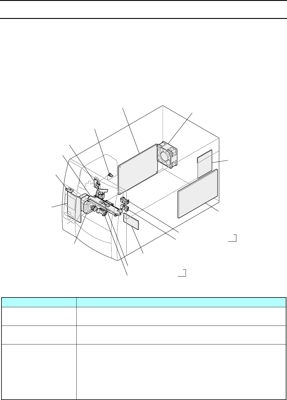
2-1-1. Locations of Main Electrical Parts
(1) CL-S700/CL-S703/CL-S700R (Printer Part)
The following figure shows the locations of main electrical parts.
Part name Description
Unit, Motor This motor feeds media. A thermistor is attached to this motor to detect
the motor temperature.
SA, Head Up SW
(Head Up Sensor)
This sensor is a mechanical switch to detect the print head position; up
or down.
Adjustable Sensor Consists of the transparent sensor and the reflective sensor that move
to right and left simultaneously by turning the adjust sensor position
knob. Together with the reflective sensor, it is used to detect a label
stuck on liner or a U-shaped notch on tag. The reflective sensor alone
is used to detect the black marks on tag. The media end is detected
with these sensors.
SA, Fan
Unit, Centro PCB
SA, Main PCB
Transparent Sensor
Reflective Sensor Adjustable Sensor
SA, Connect PCB
Unit, Power Supply
SA, Ope-pane PCB
SA, Cover Open Sens
Unit, Head
SA, Head Up SW
Unit, Motor
Reflective Sensor Front Fixed Sensor
Ribbon Encoder
(Ribbon Running Sensor/
Ribbon End Sensor)
Transparent Sensor

Chapter 2 Operating Principles
2-1. Operation of Each Mechanism
2-5 CL-S700/CL-S703/CL-S700R
Part name Description
Front Fixed Sensor Consists of the transparent sensor and the reflective sensor.
The function is the same as for adjustable sensor except that this
sensor is fixed and does not move.
SA, Cover Open Sens
(Top Cover Open Sensor)
This sensor is a photo interrupter to detect the top cover open
status.
Ribbon Encoder (Ribbon
Running Sensor/Ribbon
End Sensor)
This sensor is a photo interrupter to detect the ribbon running. It
also detects the ribbon end. (It is a part of the “Unit, Frame Ribbon
L”)
Unit, Head This is a thermal head consisting of a head driver and thermal
elements. It incorporates a thermistor to detect the thermal head
temperature.
SA, Ope-pane PCB Consists of LCD, LED and switches for operation.
SA, Main PCB Controls enter printer system.
Unit, Centro PCB This PCB is a connector board of the parallel interface.
Unit, Power Supply Converts AC to DC and feeds DC power to the circuits.
SA, Connect PCB This PCB will be used for optional cutter unit and optional peeler
unit.
SA, Fan Cooling fan that rotates during printing.
Chapter 2 Operating Principles
2-1. Operation of Each Mechanism
CL-S700/CL-S703/CL-S700R 2-6
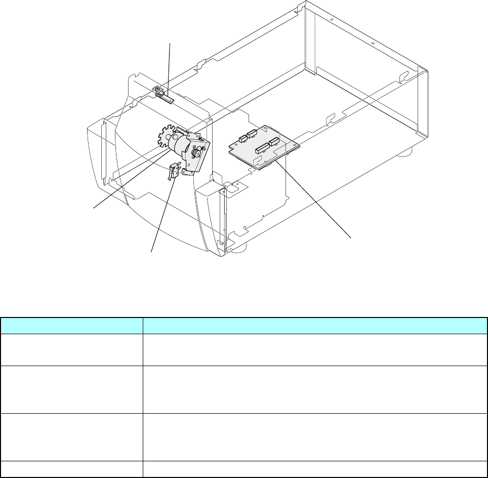
(2) CL-S700R (Rewinder Part)
The following figure shows the locations of main electrical parts for CL-S700R (Rewinder part).
Part name Description
SA, Peel Sensor This sensor is a photo reflector to detect the presence of peeled
label at the exit of the printer.
SA, Rewinder Motor Rewinds the liner of the printed media. It consists of the rewinder
motor, motor control PCB and thermistor that detects the motor
temperature.
SA, Interlock SW
(Rewinder Cover Open
Sensor)
This is a mechanical switch to detect the open/close status of the
rewinder cover.
SA, Rewinder PCB Controls the rewinder operation.
<CL-S700 (Rewinder Part)>
SA, Peeler Sensor
SA, Rewinder PCB
SA, Interlock SW
SA, Rewinder Motor
Chapter 2 Operating Principles
2-1. Operation of Each Mechanism
2-7 CL-S700/CL-S703/CL-S700R
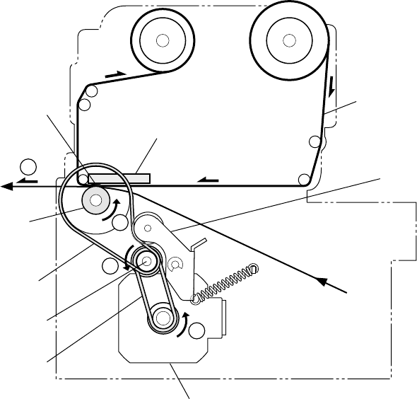
2-1-2. Media Feed Mechanism
The major components of the media feed mechanism are:
(a) Unit, Motor (d) Motor Drive Belt
(b) SA1, Drive Shaft (e) Platen Drive Belt
(c) Unit, Roller Platen (f) Tension Plate block
By setting the head block to the down position, the “Unit, Head” pushes media against the platen.
As the “Unit, Motor” (stepping motor) (located on the left) turns counterclockwise viewing from the
right side of the printer, the platen turns counterclockwise via the “Belt, Motor Drive” (on the left
side), “SA 1, Drive Shaft” (that links left and right side) and “Belt, Platen Drive” (on the right side).
Then, media is fed forward by the friction force produced between the platen and the “Unit, Head”.
Since the spring pulls the bottom of the Tension Plate block as shown in the figure, the Tension
Plate block gives an adequate tension to the “Belt, Platen Drive”.
When the “Unit, Motor” turns clockwise viewing from the right side of the printer, media is fed
reversely.
One step of the “Unit, Motor” feeds media by 1/16 mm (0.0025").
(Take-up Reel)
Thermal Element
Platen
(Unit, Roller Platen)
Belt, Platen Drive
(Right side)
Belt, Motor Drive
(Left side)
(Supply Reel)
Ribbon
Tension Plate Block
Unit, Motor (Left side)
SA1, Drive Shaft
Unit, Head
1
2
3
4
Chapter 2 Operating Principles
2-1. Operation of Each Mechanism
CL-S700/CL-S703/CL-S700R 2-8
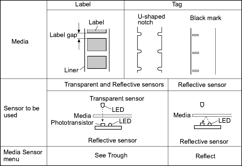
2-1-3. Label/Tag Position Detection Mechanism
The major components of the label/tag position detection mechanism are:
(a) Adjustable Sensor (consisting of transparent sensor and reflective sensor)
(b) Front Fixed Sensor (consisting of transparent sensor and reflective sensor)
By default, the Sensor Select menu is set to “Rear Adj Sensor”, and the adjustable sensor is
selected.
The Adjustable Sensor consists of the reflective sensor (bottom sensor) and the transparent
sensor (upper sensor) as shown blow. The reflective sensor consists of 1 LED and 1
phototransistor, while the transparent sensor consists of 1 LED (in practice, LED is not a sensor
but it acts as a sensor by the combination of the reflective sensor’s phototransistor).
The following table shows how the sensors detect a label, U-shaped notch or black mark.
Chapter 2 Operating Principles
2-1. Operation of Each Mechanism
2-9 CL-S700/CL-S703/CL-S700R
Detecting labels: (Media Sensor menu: “See Through”)
For detecting label on the liner, both reflective sensor and transparent sensor are used. Label
paper passes through between both sensors. The light emitted from the LED of the transparent
sensor passes through the media and reaches the phototransistor of the reflective sensor. In liner
part and label part, the amount of light that can pass through differs. Thus, the current flowing into
the phototransistor differs, and the output of the phototransistor also differs.
From the difference in outputs, the CPU on the Main PCB can detect the leading edge of label.
Detecting U-shaped notches of tag: (Media Sensor menu: “See Through”)
For detecting U-shaped notches of tag, the same principle as for detecting label applies, except
that the light is directly falls on the phototransistor through the notch.
Detecting black marks on tag: (Media Sensor menu: “Reflect”)
For detecting black marks on tag, only the reflective sensor is used. Light emitted from the LED is
reflected by the tag (at other than the black mark) and reaches the phototransistor of the reflective
sensor. At the black mark, the light is not reflected. The CPU on the Main PCB detects the black
mark by sensing the output of the phototransistor.
Detecting continuous media: (Media Sensor menu: “None”)
For detecting continuous media, only the reflective sensor is used. In this case, only media end is
detected by the reflective sensor.
Detecting media end:
For any media, media end is detected with the sensor.
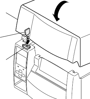
2-1-4. Top Cover Open Detection Mechanism
The component of the top cover detection mechanism is as follows:
(a) SA, Cover Open Sens
The top cover open detection mechanism detects the open/close status of the top cover.
When the top cover is closed, the claw of top cover engages with the “SA, Cover Open Sens”
(photo interrupter). While it is opened, it comes off the “SA, Cover Open Sens”.
The CPU on the Main PCB detects open/close status of the top cover by sensing the output from
the “SA, Cover Open Sens”. When the top cover is opened, the ERROR LED blinks and the LCD
displays “Error Cover Open” on the operation panel.
Claw
SA, Cover Open Sens
(Photo interrupter)
Top Cover
Chapter 2 Operating Principles
2-1. Operation of Each Mechanism
CL-S700/CL-S703/CL-S700R 2-10
2-1-5. Print Head Up/Down Detection Mechanism
The component of the print head up/down detection mechanism is as follows:
(a) SA, Head Up SW
The print head up/down detection mechanism detects the up (open)/down (close) status of the
head block.
When the head block is in the up position, the switch lever of the “SA, Head Up SW” is released
and the switch turns OFF. While, the head block is in the down position, it is pushed by the head
block and the switch turns ON.
The CPU on the Main PCB detects up or down position of the head block by sensing the switch
output of the “SA, Head Up SW”. When the head block is in the up position, the ERROR LED
blinks and the LCD displays “ERROR HEAD OPEN” on the operation panel.
Head Block
Switch OFF
Head Block
[Rear View]
Switch ON
SA, Head Up SW
Chapter 2 Operating Principles
2-1. Operation of Each Mechanism
2-11 CL-S700/CL-S703/CL-S700R
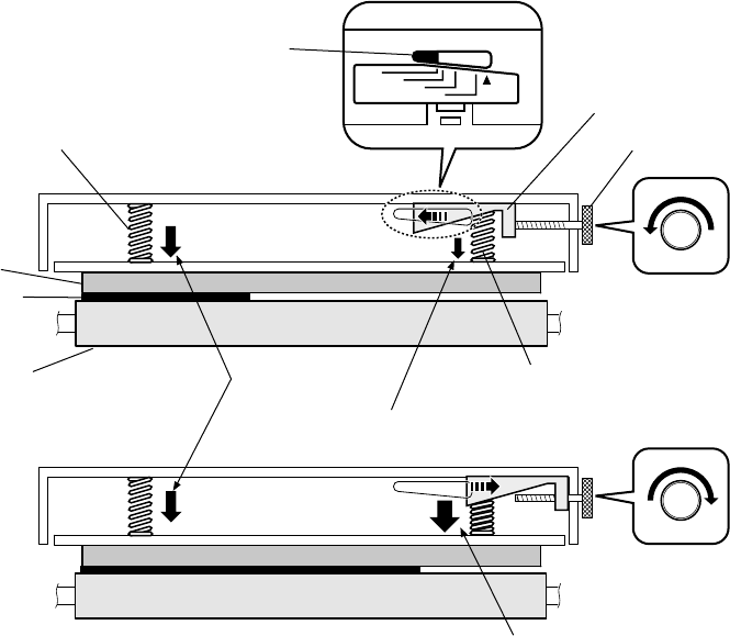
2-1-6. Head Balance Adjustment Mechanism
The major components of the head balance adjustment mechanism are:
(a) Adjust Screw (Media width adjustment knob)
(b) Slider
(c) Head Spring L/R
The head balance adjustment mechanism is used to eliminate uneven printing density on the left
and right sides of media. The head balance adjustment is accomplished by changing the right side
head pressure according to media width to be used. To change it, the Adjust Screw (Media width
adjustment knob) is used.
When narrow media is used (needs to give weak pressure on the right side):
As you can see from the figure, the Head Spring L pushes the left side “Unit, Head” against the
platen, at a constant pressure. While the Head Spring R pushes the right side “Unit, Head” against
the Platen SA via the Slider. Since the Slider has taper shape on its bottom, the pressure that is
developed by the Head Spring R varies with the Slider position. As the Slider moves toward the left
(or the Adjust Screw is turned counterclockwise), the Head Spring R gives a weaker pressure to
the “Unit, Head”. While, it moves to the right, a stronger pressure is given.
For example, when narrow media is set, since no media exists on the right side, the right side
pressure of the “Unit, Head” must be weak. Otherwise, the “Unit, Head” will slant toward the right
and pressure is not appropriately given to narrow media, resulting in uneven printing density.
To obtain optimum printing result, you need to move the Slider to the left by turning the Adjust
Screw, while viewing the indicator in the media width check window.
25 50 75 100(mm)
Head Spring L
Head Spring R
Platen
Head Unit
Constant
pressure
Pressure: Low
Pressure: High
Adjust Screw
Slider
Media width
check window
[For wide media]
[For narrow media]
Media
Chapter 2 Operating Principles
2-1. Operation of Each Mechanism
CL-S700/CL-S703/CL-S700R 2-12
When wide media is used (need to give strong pressure on the right side):
The same principle applies to wide media. However, in this case, since the media is wide, the
Slider should be moved toward the right (or the Adjust Screw should be turned clockwise) to get
stronger pressure by the Head Spring R.
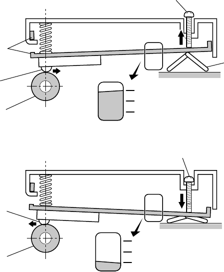
2-1-7. Media Thickness Adjustment Mechanism
The major components of the media thickness adjustment mechanism are:
(a) Media thickness adjustment screw (c) Offset Spring
(b) Head Plate
According to the change in media thickness, the thermal element position of the “Unit, Head”
changes slightly. The media thickness adjustment mechanism is used to correct this change by
moving the thermal element position back and forth a little, by turning the media thickness
adjustment screw. With this adjustment, optimum printing quality is obtained.
For thin media (standard label, thermal media, etc.):
For thin media, normally, the media thickness adjustment screw will be turned counterclockwise 2
to 4 turns from the center line of the media thickness check window.
As shown in the figure, when the media thickness adjustment screw is turned counterclockwise
from the center position, the right end of the Head Plate is pushed up by the Offset Spring and the
thermal element parts slightly moves to the right.
Media Thickness Adjustment Screw
Offset Spring
Platen
Head Unit
(Thermal elements)
Head Plate
[For thick media (tag)]
[For standard label/thermal media]
Media Thickness Adjustment Screw
Platen
Head Unit
(Thermal elements)
Media Thickness
Check Window
Media Thickness
Check Window

Chapter 2 Operating Principles
2-1. Operation of Each Mechanism
2-13 CL-S700/CL-S703/CL-S700R
For thick media (tag paper):
For thick media, normally, the media thickness adjustment screw will be turned further clockwise 2
to 4 turns from the center line of the media thickness check window. When the media thickness
adjustment screw is turned clockwise further from the center position, the right end of the Head
Plate is lowered and the thermal element parts slightly moves to the left.
Shipping position:
It is the position where the screw is turned by 2 turns counterclockwise from the center line (head
offset “0”) of the media thickness check window.
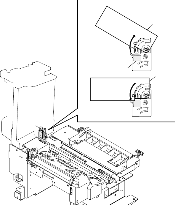
2-1-8. Rewinder Cover Open Detection Mechanism (CL-S700R only)
The component of the rewinder cover detection mechanism is as follows:
(a) SA, Interlock SW (Rewinder Cover Open Sensor)
The rewinder cover open detection mechanism detects the open/close status of the rewinder
cover.
When the rewinder cover is closed, the lever of the interlock switch is pushed by the plate “A” and
it turns ON. While the rewinder cover is opened, the plate “A” comes off the interlock switch and
the switch turns OFF.
The CPU on the Main PCB detects open/close status of the rewinder cover by sensing the output
from the “SA, Interlock SW”.
When the rewinder cover is opened, the ERROR LED blinks and the LCD displays “Error Rewinder
Open” on the operation panel.
ON OFF
(Rewinder Cover)
SA, Interlock SW
SA, Interlock SW
A
Chapter 2 Operating Principles
2-1. Operation of Each Mechanism
CL-S700/CL-S703/CL-S700R 2-14
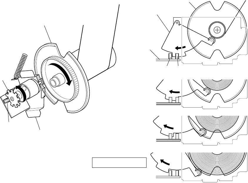
2-1-9. Rewinding Mechanism (CL-S700R only)
The components of the rewinding mechanism are as follows:
(a) SA, Rewinder Motor (c) Measure Flap Plate
(b) SA, Rewinder Flange (e) SA, Rewinder PCB
As the rewinder motor turns, the “SA, Rewinder Flange” turns to wind up the liner. The Measure
Flap Plate is pushed by the wound liner and turns backward and passes the form sensor (photo
interrupters PS501/PS502) on the “SA, Rewinder PCB”. The amount of liner wound up at the
flange is divided into four stages as follows (refer to the figure):
1st stage: PS501: ON, PS502: OFF
2nd stage: PS501: ON, PS502: ON
3rd stage: PS501: OFF, PS502: ON
4th stage (Full): PS501: OFF, PS502: OFF
The rewinder motor speed to wind up the liner is changed in 1st to 3rd stages (fast to slow).
When the Full state is detected, the CPU stops rewinder motor. In this state, the ERROR LED
blinks and the LCD displays “Error Rewinder Full” on the operation panel.
When printing is performed, the rewinder motor starts to turn to wind up the liner. Turning of the
motor is detected by photo interrupter of the “SA, Rewinder PCB”. While the motor is turning, the
blade at the end of motor turns and the intermittent pulse is output to the CPU from the photo
interrupter. When the flange tightly wound up the liner, the motor stops as it cannot run further. In
this state, since no pulse is output from the photo interrupter, the CPU judges that the liner has
wound up and stops the motor. Above winding cycle is repeated for the next printing.
[Viewed from the left of the Rewinder Part]
SA, Rewinder Flange
SA, Rewinder Motor
(Photo Interrupter)
(Blade)
Liner
Plate, Measure Flap
SA, Rewinder Flange
PS501PS502
SA, Rewinder
PCB
Liner
Error: Rewinder Full
Chapter 2 Operating Principles
2-2. Operation of Control Parts
2-15 CL-S700/CL-S703/CL-S700R
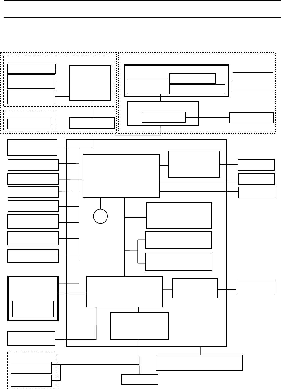
2-2. Operation of Control Parts
2-2-1. Configuration of Printer
The following shows major configuration blocks.
SA, Rewinde
r
Moto
r
BZ
PF Moto
r
Thermal Print
Head
SA, Ope-pane
PCB
(SW & LED)
Main PCB
(Option) Auto Cutter Unit
Ethernet I/F
Wireless LAN
LAN I/F (Option)
A/D
A/D
A/D
A/D
Rewinde
r
Unit
A/D
A/D
LCD
(Serial Data)
Rewinde
r
PCB
Head Up Senso
r
Front Fixed Senso
r
Thermal Head
Temp. Sensor
PF Motor
Temp. Sensor
Adjustable Senso
r
RF-ID R/W
(Serial Data)
Ribbon Encode
r
Cover Open
Sensor
CPU
UPD703111AGM-13-UEU-A
128MHz
AC Inlet & Power Switch/
Filter & Power Supply
S-DRAM (128Mbits)
Control / C.G.
F-ROM(32Mbit)
PF Moto
r
Driver
SLA7033M
RS232C
USB 1.1
RS232C
Driver/Receiver
IEEE1284
Transceiver
Rewinder Moto
r
(
DC
)
Form Senso
r
Encode Senso
r
Fan
D/A Converte
r
- PF motor current
- PE sensor LED
- Rewind motor current
Rewinder Motor
Tem
p
. Senso
r
Custom IC (Gate Array)
UPD65946GJ-165-3EB-A
IEEE1284
Cutter Moto
r
Cutter Position
Sensor
Cutter Moto
r
Temp. Sensor
(Option) Peeler Unit
Peel Senso
r
Connect PCB
Peeler Unit
Peel Senso
r
A/D
Rewinder Cover
Open Sensor
Cutter PCB
(CL-S700/CL-S703) (CL-S700R)
Chapter 2 Operating Principles
2-2. Operation of Control Parts
CL-S700/CL-S703/CL-S700R 2-16
Major functions of individual components are described below:
(1) AC Inlet & Power Switch/Filter & Power Supply section
Consists of a fuse, a filter circuit to eliminate external electric noise, and a switching type
regulator to transform an AC input to +5V DC and +24V DC outputs required to drive the
printer.
(2) Main PCB
Controls the entire operations of the printer. It consists of CPU, Flash ROM, S-DRAM, Custom
IC (Gate Array), driver circuits, etc.
(a) CPU
The CPU is a microprocessor with 32-bit architecture. The clock fed to the CPU is 16 MHz.
The CPU internally multiplies this 16 MHz by 8 times and uses 128 MHz clock. The CPU
includes cache memory, RAMs, DMA controller, serial I/F, USB function controller, A/D
converter, etc.
(b) Flash ROM
This is a flash ROM of 32M bits (4M bytes) that stores the firmware and CG (character
generator).
(c) S-DRAM (Synchronous dynamic RAM)
This is an S-DRAM of 128M bits (16M bytes) that is used as working area, input buffer and
download buffer.
(d) Custom IC (Gate Array)
The custom IC incorporates a control circuit for the interface I/O port, motor, print head,
etc.
(e) PF motor driver
This is a circuit to drive the PF Motor. The PF Motor is a stepping motor.
(f) Buzzer
The buzzer is driven when an alarm, etc. occurs.
(g) Fan
This is a cooling fan at the left rear of the printer. Rotation of the fan is controlled by the
CPU and the fan rotates during printing. The CPU monitors fan lock signal to check for any
fan abnormality. If the fan stops during printing, ERROR LED blinks and “Error Fan Lock” is
displayed on the operational panel.

Chapter 2 Operating Principles
2-2. Operation of Control Parts
2-17 CL-S700/CL-S703/CL-S700R
(3) Operation panel
This is a panel used to indicate the operating status of the printer and to set specifications. It
consists of 4 keys, 6 LEDs and 1 LCD.
(4) Thermal print head
The thermal print head has the following thermal elements. It also has the print head driver
circuit.
• 864 dots (CL-S700/CL-S700R)
• 1275 dots (CL-S703)
(5) Sensors
CL-S700/CL-S703/CL-S700R (Printer Part):
The following 9 sensors are used:
Sensor name Description
Top Cover Open Sensor It is a photo interrupter to detect top cover open. (“SA,
Cover Open Sens”)
Head Up Sensor It is a mechanical switch (“SA, Head Up SW”) to
detect head open/close status.
Each transparent sensor:
Consists of 1 LED.
Adjustable Sensor and Front Fixed
Sensor
(Consists of the transparent sensor
and reflective sensor.)
Each reflective sensor:
Consists of 1 LED and 1 phototransistor.
Thermal Head Temp. Sensor A thermistor incorporated in the print head.
PF Motor Temp. Sensor A thermistor attached to the PF Motor.
Ribbon Encoder (Ribbon Running
Sensor/Ribbon End Sensor)
A photo interrupter to detect ribbon running. It also
detects the ribbon end. (A part of the “Unit, Frame
Ribbon L”.)
CL-S700R (Rewinder Part):
The following 5 sensors are used:
Sensor name Description
Peel Sensor It is a photo reflector to detect the presence of peeled
label at the exit of the printer.
Rewinder Cover Open Sensor It is a mechanical switch to detect rewinder cover
open/close status. (SA, Interlock SW)
Form Sensor Two photo interrupters that are used to detect the
amount of liner wounded by the flange. Full state is
also detected. (PS501 and PS502 on the “SA,
Rewinder PCB”.)
Encode Sensor A photo interrupter to detect the running of rewinder
motor. (A part of the “SA, Rewinder Motor”)
Rewinder Motor Temp. Sensor A thermistor attached to the rewinder motor.
(A part of the “SA, Rewinder Motor”)
(6) Motors
Chapter 2 Operating Principles
2-2. Operation of Control Parts
CL-S700/CL-S703/CL-S700R 2-18
PF motor is used. It is a stepping motor to feed media. Ribbon will be fed with the media
through developed friction force.
Rewinder motor is used (CL-S700R only). It is a DC motor to turn the rewinder flange for
winding up liner.
(7) Parallel I/F (IEEE1284)
This is a parallel I/F to transmit and receive parallel data between the printer and a host. It
supports Centronics Compatible mode, NIBBLE mode and ECP mode.
Parallel I/F, serial I/F, or USB I/F is automatically selected when data is received.
(8) Serial I/F (RS-232C)
This is a circuit to transmit and receive serial data between the printer and the host.
Parallel I/F, serial I/F, or USB I/F is automatically selected when data is received.
(9) USB (Universal Serial Bus) I/F
This is a circuit to transmit and receive serial data between the printer and the host using the
USB.
Parallel I/F, serial I/F, or USB I/F is automatically selected when data is received.
(10) Ethernet I/F (Option)
This is a circuit which supports Ethernet protocol. LAN connection is possible.
(11) Wireless LAN I/F (Option)
This is a circuit which supports Ethernet protocol. Wireless LAN connection is possible.
(12) Connect PCB
This is a relay PCB to connect optional peeler unit and auto cutter unit.
Chapter 2 Operating Principles
2-2. Operation of Control Parts
2-19 CL-S700/CL-S703/CL-S700R
2-2-2. Memory Map
Command RAM
(Built-in CPU)
0000000
H
001FFFF
H
Flash ROM
4M bytes
0100000
H
0103FFF
H
0104000
H
0105FFF
H
0106000
H
0107FFF
H
0108000
H
010FFFF
H
0110000
H
027FFFF
H
0280000
H
03BFFFF
H
03C0000
H
04BFFFF
H
04E0000
H
04EFFFF
H
Custom IC
SDRAM
0800000
H
16M bytes
0FFFFFF
H
CPU
FFFB000
H
FFFEFFF
H
FFFF000
H
FFFFFFF
H
CPU
Boot Loader (1)
Setting Information
(User Settings)
Setting Information
(Factory-set Settings)
Boot Loader (2)
Firmware (Datamax)
Firmware (Zebra)
Service Information (Backup)
Downloading Area (1M bytes)
Firmware (about 400K bytes)
Receiving Buffer (16K bytes x 3)*
Command Buffer (128K bytes)
Others *: 16K bytes for each I/F
(USB, IEEE1284 and Serial)
I/O (Built-in CPU)
Data RAM (Built-in CPU)
04F0000
H
04FFFFF
H
Service Information
4000000
H
40FFFFF
H
I/O
Chapter 2 Operating Principles
2-2. Operation of Control Parts
CL-S700/CL-S703/CL-S700R 2-20
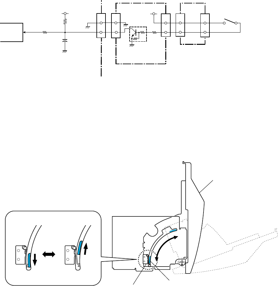
2-2-3. Sensors
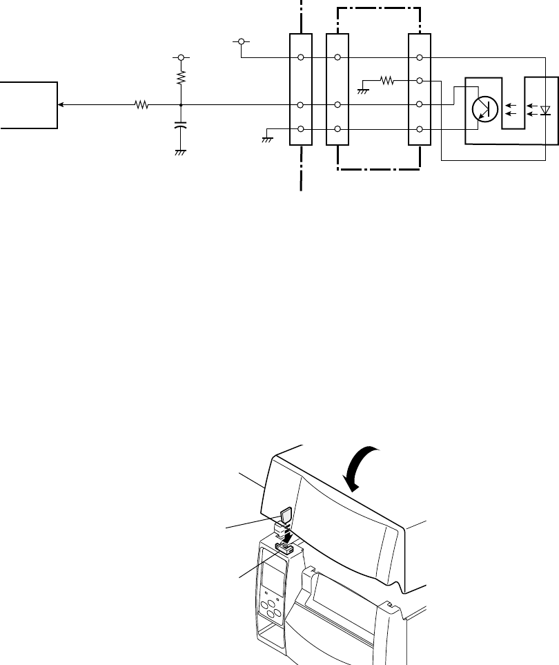
(1) Top cover open sensor
The top cover open sensor is used to detect the open/close status of the top cover. This sensor
uses a photo interrupter.
When the top cover is closed, the claw of the top cover is engaged with the photo interrupter
(top cover open sensor). In this case, light emitted from the LED of the photo interrupter is
blocked by the claw and the phototransistor turns OFF. As a result, pin 173 (CV_OPN) of U1
(CPU) goes "High".
When the top cover is opened, the claw is released from the photo interrupter and pin 173
(CV_OPN) of U1 (CPU) goes "Low".
When the top cover is opened, the ERROR LED blinks and the LCD displays “ERROR
COVER OPEN” on the operation panel.
Claw
SA, Cover Open Sens
(Photo interrupter)
Top Cover
+3.3V
R190
R191
J403
+5V
1
[Main PCB]
CV_OPN
U1 CPU
P75 173
C113
19
22
Cover Open Sensor
1
[Ope-pane PCB]
2
3
4
22
4
1
J401
J14
R406
Chapter 2 Operating Principles
2-2. Operation of Control Parts
2-21 CL-S700/CL-S703/CL-S700R
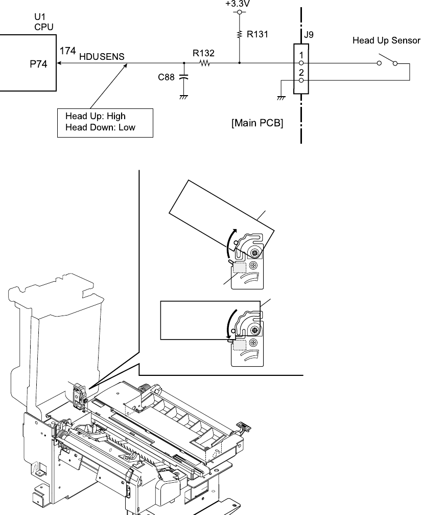
(2) Head up sensor
The head up sensor (“SA, Head Up SW”) is used to detect the head position (up or down). This
sensor uses a mechanical micro switch.
When the head block is closed (in the down position), the head block pushes the micro switch
lever and the micro switch turns ON. In this state, pin 174 (HDUSENS) of U1 (CPU) goes
"Low".
When the head block is opened (in the up position), the micro switch turns OFF and pin 174
(HDUSENS) of U1 (CPU) goes "High".
When the head block is opened, the ERROR LED blinks and the LCD displays “ERROR HEAD
OPEN” on the operation panel.
Head Block
Switch OFF
Head Block
[Rear View]
Switch ON
SA, Head Up SW
Chapter 2 Operating Principles
2-2. Operation of Control Parts
CL-S700/CL-S703/CL-S700R 2-22
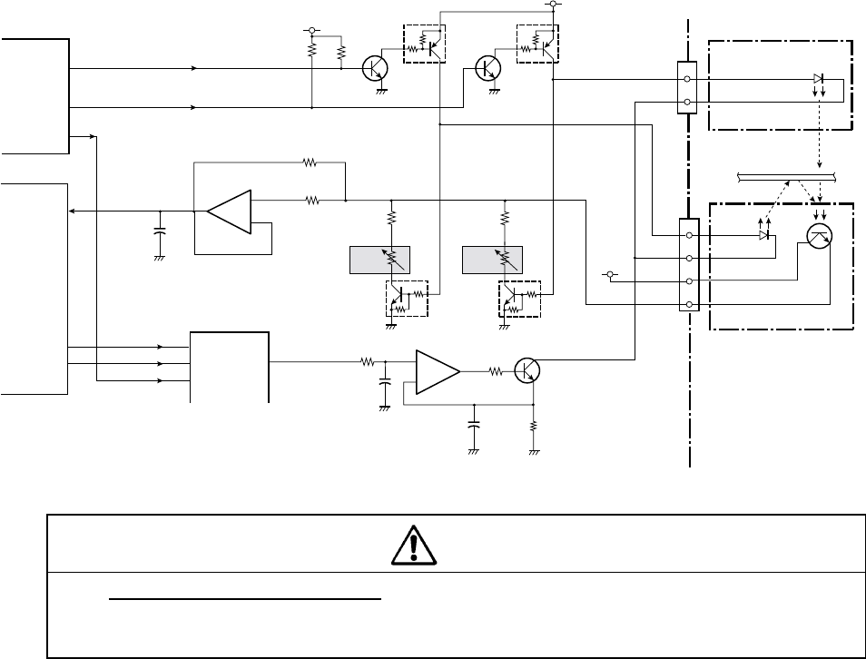
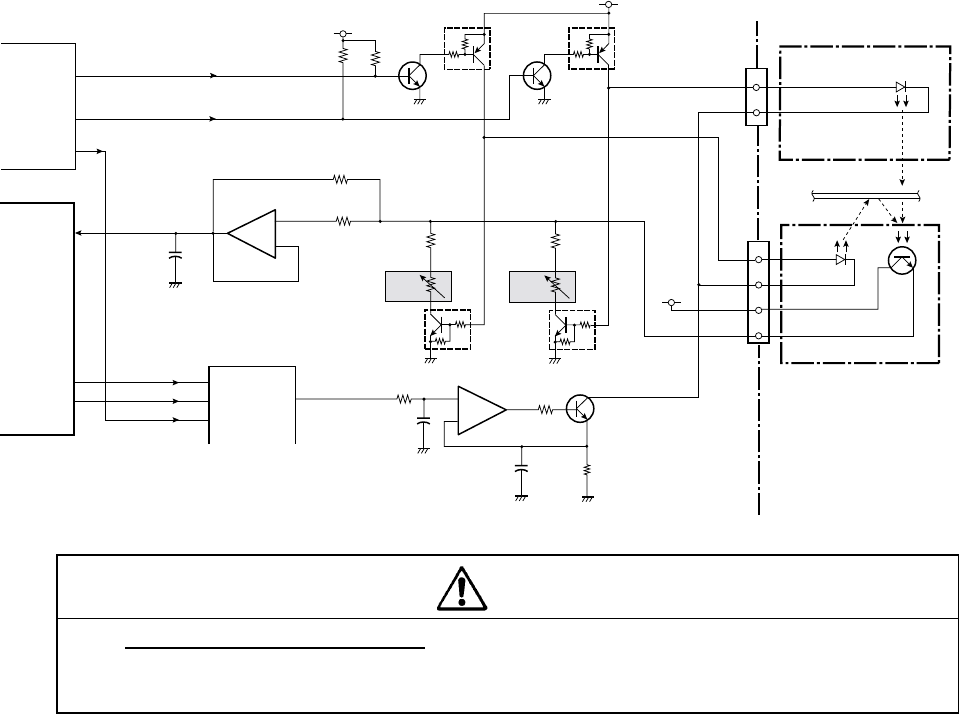
(3) Adjustable Sensor
The adjustable sensor consists of the transparent sensor (upper sensor) and the reflective
sensor (lower sensor), and media passes between these sensors.
The transparent sensor and reflective sensor are used to detect the label stuck on liner and the
U-shaped notch on tag. While the reflective sensor alone is used to detect the black mark on
the bottom surface of tag. Both sensors are also used to detect the media end.
The transparent sensor consists of 1 LED (this is not a sensor actually but it acts as the
transparent sensor by the combination of the phototransistor in the reflective sensor). The
reflective sensor consists of 1 LED and 1 phototransistor.
- DO NOT adjust VR3 and VR4 on the Main PCB. (Leave them at the factory
setting condition.) If it is turned, media sensor sensitivity is changed and the
media detection will not be correctly made.
Transparent sensor (used for detecting the label or U-shaped notch):
When transparent sensor is used together with the reflective sensor (media sensor menu: See
Through), pin 99 (LEDMOVE_T) of U14 (Custom IC) goes “High”, Q28 and Q9 turn ON and
the LED of the transparent sensor turns ON. The current flowing into the LED (the light amount
to be emitted) for detecting label is determined by U4 (D/A converter), U5B and Q10 under the
control of the U1 (CPU) and U14 (Custom IC).
When the liner (without label stuck on it) passes between both transparent and reflective
sensors, the light emitted from the LED of the transparent sensor reaches the phototransistor
of reflective sensor, passing through the liner.
Thus, the phototransistor conducts and the voltage corresponding to the amount of light
received is applied to the analog input (pin 6 (SENSMOVE)) of U1 (CPU) via OP amp. U20B.
Media
SA, Sensor U
[Main PCB]
SA, Sensor Bottom
2
3
4
1
J7
2
1
[Transparent Sensor]
[Reflective Sensor]
J22
UP LED A
UP LED K
DOWN
LED A
DOWN
LED K
DOWN TR C
DOWN TR E
Q9
+5V
Q28
Q8
Q27
LEDMOVE_R
LEDMOVE_T
+3.3V
Q10
C85
-
+
7
5
6
C86 R127
R126
R125
R207
VR4
VR3
R124
R122
U20B
BA2904
-
+5
6
7
R120
C83
SENSMOVE
77
ANI1 6
U1 CPU
DTA114EM
DTA114EM
2SC56582SC5658
+3.3V
R202
R203
U4
CSB
10
DI
12
CLK
11
AO1 1
AO2 2
AO3 5
BH2227
DACIN
DACCLK
145
147
P25
P23
PFCNT2
U14
Custom IC
PFCNT1
100
99
OPRS
CS_DAC
Q21
DTC114EM
Q20
DTC114EM
2SC5658
U5B
BA2904
DO NOT
ADJUST!
DO NOT
ADJUST!
PESENSLED
Caution
Chapter 2 Operating Principles
2-2. Operation of Control Parts
2-23 CL-S700/CL-S703/CL-S700R
The CPU senses this voltage and judges that the light is passing through media, namely, the
liner part without label is now passing through the sensors.
When the label part arrives at the sensors, the light is blocked by the label and does not reach
the phototransistor. So, the phototransistor turns OFF and pin 6 (SENSMOVE) of U1 (CPU)
goes from “High” to "Low". From this level change, the CPU can detect the leading edge
(arrival) of the label on the liner.
If media runs out, the light directly falls on the phototransistor and the phototransistor
continuously turns ON. From this, media end is detected.
The above principle applies when media with U-shaped notch is used. In this case, since the
light directly falls the phototransistor, the current flowing into the LED (the amount of light
emitted) is appropriately set for detecting the U-shaped notch.
Reflective sensor (used for detecting the black mark on tag):
The reflective sensor alone is used (media sensor menu: Reflect). In this case, pin 100
(LEDMOVE_R) goes “High”, Q27 and Q8 turn ON and the LED of the reflective sensor turns
ON. The current flowing into the LED (the light amount to be emitted) for detecting black mark
is determined by U4 (D/A converter), U5B and Q10 under the control of the U1 (CPU) and U14
(Custom IC).
When tag with black marks is used, light emitted from the LED is reflected by the tag and
reaches the phototransistor. At the place where no black mark exists, the phototransistor
receives the reflected light and conducts. So, the voltage corresponding to the amount of light
received is applied to the analog input (pin 6 (SENSMOVE)) of U1 (CPU) via U20B. When the
light falls on the black mark, no light is reflected, the phototransistor turns OFF, and pin 6 of U1
(CPU) goes “Low”.
When media runs out, the light is not reflected by media any more and the phototransistor
continuously turns OFF. From this, media end is detected.
Chapter 2 Operating Principles
2-2. Operation of Control Parts
CL-S700/CL-S703/CL-S700R 2-24
(4) Front Fixed Sensor
The principle of the front fixed sensor is the same as that of the adjustable sensor.
To use the front fixed sensor, you need to change the Sensor Select menu from “Rear Adj
sensor” to “Front Fixed Sen”.
- DO NOT adjust VR1 and VR2 on the Main PCB. (Leave them at the factory
setting condition.) If it is turned, media sensor sensitivity is changed and the
media detection will not be correctly made.
Media
SA, Sensor U
[Main PCB]
SA, Sensor Bottom
2
3
4
1
J6
2
1
[Transparent Sensor]
[Reflective Sensor]
J21
UP LED A
UP LED K
DOWN
LED A
DOWN
LED K
DOWN TR C
DOWN TR E
Q7
+5V
Q26
Q6
Q25
LEDFIX_R
LEDFIX_T
+3.3V
Q10
C85
-
+
7
5
6
C86 R127
R126
R125
R206
VR2
VR1
R121
R118
U20A
BA2904
-
+3
2
1
R117
C81
SENSFIX
77
ANI0 5
U1 CPU
DTA114EM
DTA114EM
2SC56582SC5658
+3.3V
R200
R201
U4
CSB
10
DI
12
CLK
11
AO1 1
AO2 2
AO3 5
BH2227
DACIN
DACCLK
145
147
P25
P23
LED1
U14
Custom IC
LED2
94
93
OPRS
CS_DAC
Q19
DTC114EM
Q18
DTC114EM
2SC5658
U5B
BA2904
DO NOT
ADJUST!
DO NOT
ADJUST!
PESENSLED
Caution
Chapter 2 Operating Principles
2-2. Operation of Control Parts
2-25 CL-S700/CL-S703/CL-S700R
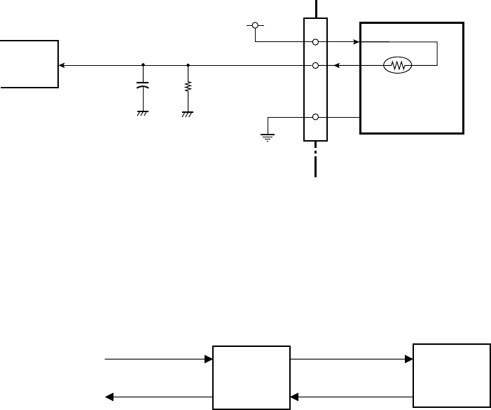
(5) Head temperature sensor
The head temperature sensor is used to detect the temperature of the thermal head (“Unit,
Head”). This sensor is a thermistor incorporated in the thermal head. Since the resistance of
the thermistor changes according to the temperature change, the voltage at pin 7 (HDTMP) of
U1 (CPU) changes accordingly. The CPU senses the voltage at pin 7 to detect the head
temperature. According to the temperature of the thermal head, the CPU controls the width of
printing pulse that is used to heat the thermal elements, to keep the printing density constant.
Printing operation when the head temperature rises abnormally:
When the head temperature rises to 70°C (158°F), printing stops after printing the current label.
In this case, the ERROR LED blinks and the LCD displays "Alarm Head Hot" on the operation
panel. When the head temperature falls below 60°C (140°F), the ERROR LED stops blinking,
the LCD returns to the original display “On Line”, and printing resumes.
Printing operation when the head temperature is too lower:
When the head temperature is lower than -10°C (14°F), printing is inhibited, and the ERROR
LED blinks and the LCD displays "Error Head Cold" on the operation panel. Printing is not
possible until the temperature of the thermal head gets warm.
60°C
(140°F)
70°C
(158°F)
Printing
(Stop)
Printing
Printing
(Stops)
J3 Thermal Head
5-8, 21-25
+3.3V
19
R102
HDTMP
U1 CPU
ANI2
7
Thermal Head
Temp. Sensor
(Thermistor)
[Main PCB]
HDTMP
C64
20
Chapter 2 Operating Principles
2-2. Operation of Control Parts
CL-S700/CL-S703/CL-S700R 2-26
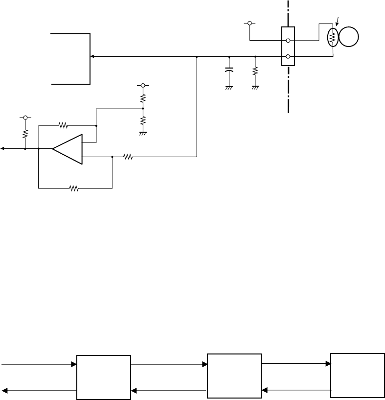
(6) PF motor temperature sensor
The PF motor temperature sensor is used to detect the temperature of the PF Motor. This
sensor is a thermistor bonded to the PF Motor. Since the resistance of the thermistor changes
according to the temperature change, the voltage at pin 8 (MOTTMP) of U1 (CPU) changes
accordingly. The CPU senses the voltage at pin 8 to detect the PF motor temperature.
Printing operation when the PF motor temperature rises:
When the temperature of the PF motor rises to 95°C (203°F), printing speed is reduced to
avoid overheating. If it reaches 105°C (221°F), the PF motor stops after printing the current
label. In this case, the ERROR LED blinks and the LCD displays "Alarm PFMotor Hot" on the
operation panel.
When the temperature of the PF motor falls below 90°C (194°F), the LED stops blinking, the
LCD returns to the original display “On Line”, and printing resumes.
In addition to the PF motor temperature rise detection by the CPU, the circuitry composed of
U19A OP amp. detects the high temperature over 130°C (266°F) to protect the PF motor. If the
PF motor temperature exceeds 130°C (266°F), the output of U19A is reversed and TEMPOFF
signal goes “Low”. As a result, +24V supply to the PF motor driver circuit is shut off. (For a
detailed description, refer to 2-2-4 “(1) PF motor driver(1) PF motor driver(1) PF motor driver”.)
When the PF motor temperature falls below 125°C (257°F), the output of U19A returns from
“Low” to “High” so that +24V supply to the PF motor driver circuit resumes.
90°C
(194°F)
95°C
(203°F)
Normal speed
(Stop)
Normal speed
Normal speed
105°C
(221°F)
Low speed (Stops)
(Stop)
1
J5
MPF Motor
2
PF Motor Temp. Sensor
(Thermistor)
VREF
R110
C78
U1 CPU
[Main PCB]
MOTTMP
ANI3
8
TMPOFF
(To PF Motor Driver)
VREF
U19A
uPC393GR-9LG
-
+3
2
1
VREF
R112
R114
R113
R115
R111
R116
Chapter 2 Operating Principles
2-2. Operation of Control Parts
2-27 CL-S700/CL-S703/CL-S700R
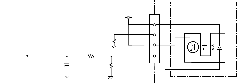
(7) Ribbon encoder
The ribbon encoder is a photo interrupter to detect ribbon running and ribbon end, and is
incorporated in the ribbon unit (“Unit, Frame Ribbon L”). A bladed wheel is mounted on the
supply reel of the ribbon unit. When the supply reel turns, the blades intermittently block the
light emitted from the LED of the ribbon encoder. Thus, while the ribbon is running (supply reel
is rotating), a pulse train is input to pin 76 (RIBENC) of U1 (CPU). With this pulse input, the
CPU can detect tape running and tape end.
J8
+3.3V
1
R130
[Main PCB]
R129
RIBENC
U1 CPU
A0 76
C87
R128
2
3
4
Ribbon Encoder
(Ribbon Running/
Ribbon End Sensor)
Ribbon Unit
Chapter 2 Operating Principles
2-2. Operation of Control Parts
CL-S700/CL-S703/CL-S700R 2-28
(8) Rewinder cover open sensor (CL-S700R only)
The rewinder cover open sensor is used to detect the open/close status of the rewinder cover.
This sensor uses a mechanical switch.
When the rewinder cover is closed, the lever of the “SA, Interlock SW” (rewinder cover open
sensor) is pressed by “A” and the switch turns ON. As a result, pin 175 (OPN) of U1 (CPU)
goes "Low".
When the rewinder cover is opened, the switch turns OFF and pin 175 (OPN) of U1 (CPU)
goes "High".
When the rewinder cover is opened, the ERROR LED blinks and the LCD displays “Error
Rewinder Open” on the operation panel.
+3.3V
R164
R166
J504
2
[Main PCB]
OPN
U1 CPU
P73 175
C100
5
1
[Rewinder PCB]
2
2
5
J502
J16 J702
1
[SA, Rewinder Motor]
2
J701 Rewinder Cover Open Sensor
(SA, Interlock SW)
1
2
Q507
DTC114EM
R513
+RW
ON OFF
(Rewinder Cover)
SA, Interlock SW
SA, Interlock SW
A
Chapter 2 Operating Principles
2-2. Operation of Control Parts
2-29 CL-S700/CL-S703/CL-S700R
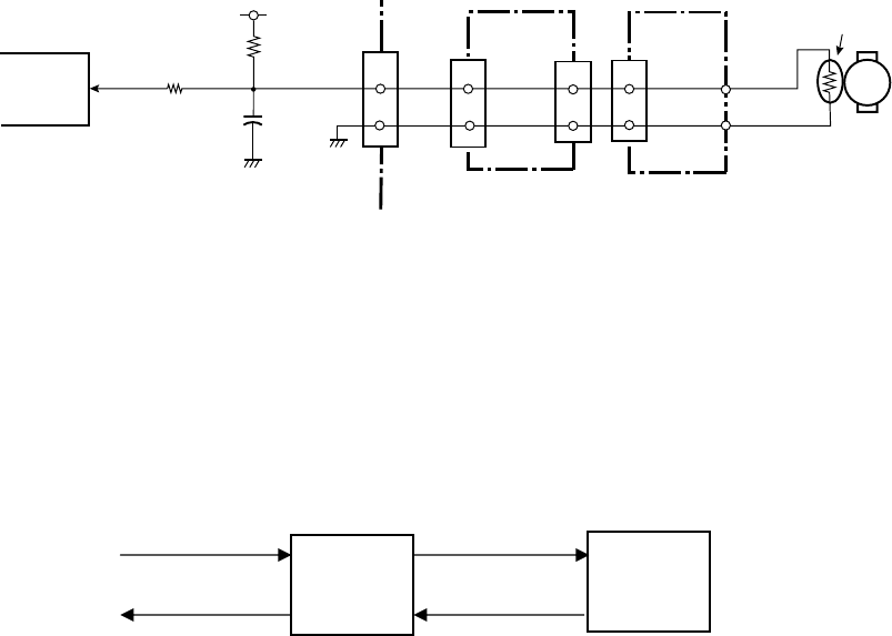
(9) Rewinder motor temperature sensor (CL-S700R only)
The Rewinder motor temperature sensor is used to detect the temperature of the rewinder
motor. This sensor is a thermistor bonded to the rewinder motor. Since the resistance of the
thermistor changes according to the temperature change, the voltage at pin 11 (MTTH) of U1
(CPU) changes accordingly. The CPU senses the voltage at pin 11 to detect the rewinder
motor temperature.
Rewinding operation when the rewinder motor temperature rises:
When the temperature of the rewinder motor rises to 110°C (230°F), printing/rewinding stops.
In this case, the ERROR LED blinks and the LCD displays "Alarm Rewinder Hot" on the
operation panel.
When the temperature of the rewinder motor falls below 100°C (212°F), the LED stops blinking,
the LCD returns to the original display “On Line”, and printing/rewinding resumes.
100°C
(212°F)
110°C
(230°F)
Printing
(Stop)
Printing
Printing
(Stops)
J504
4
[Rewinder PCB]
5
10
5
J501
[SA, Rewinder Motor]
J701
4
5
Rewinder Motor
Rewinder Motor Temp. Sensor
(Thermistor)
+3.3V
R155
R16
10
[Main PCB]
MTTH
U1 CPU
AN16 11
C98
5
J15
M
Chapter 2 Operating Principles
2-2. Operation of Control Parts
CL-S700/CL-S703/CL-S700R 2-30
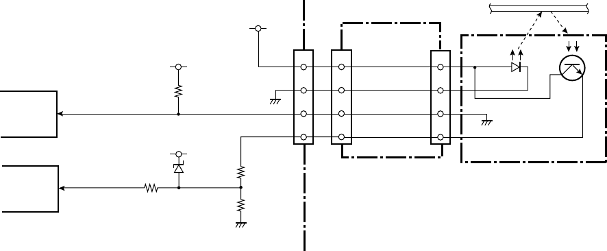
(10) Peel sensor (CL-S700R only)
The peel sensor is used to detect the peeled label at the exit of the printer.
This sensor is a reflective sensor.
When a peeled label exists at the exit of the printer, the light emitted from the LED of the peel
senor is reflected by the label and reaches the phototransistor. Thus, the voltage at pin 12
(PEELSENS) of U1 (CPU) becomes “High”. The CPU senses the voltage at pin 12 to detect
the presence of label at the exit.
When no label exists at the exit of the printer, the light emitted from the LED does not reach the
phototransistor. Thus, the voltage at pin 12 (PEELSENS) of U1 (CPU) becomes “Low”.
CRPTYP1 signal (pin 96 (PM1) of U14 (Custom IC)) is used to detect whether the “SA, Peel
Sensor” is installed in the CL-S700R or not.
[Main PCB]
U1 CPU
AN17
Peeled label
SA, Peel Sensor
3
5
4
2
[Peel Sensor]
J503
7
6
1
2
J502
+5.0V
[Rewinder PCB]
R167
R169
D9
+3.3V
R168
12
PEELSENS
U14
Custom IC
PM1 CRPTYP1
96
7
6
1
2
J16
+3.3V
R16
Chapter 2 Operating Principles
2-2. Operation of Control Parts
2-31 CL-S700/CL-S703/CL-S700R
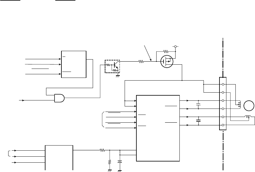
2-2-4. Drivers
(1) PF motor driver
This is a driving circuit to drive the PF Motor (stepping motor). The following illustration shows
a simplified circuit. The PF Motor is driven by the unipolar constant current chopper method.
The exciting method for the motor is the 2-phase method.
The power to the PF Motor is supplied by turning ON the FET Q4. This is accomplished by
activating the monostable multivibrator U16A. When U16A is triggered, Q5 turns ON and FET
Q4 turns ON. (TEMPOFF signal is normally at “High”. If the PF motor temperature rises
excessively, TEMPOFF signal goes “Low” and the output from U16A is inhibited. Thus, +24V to
the PF Motor is shut off. For TEMPOFF signal, refer to 2-2-3 “(6) PF motor temperature
sensor”.)
PFMA, PFMA, PFMB and PFMB signals are the exciting pulses to drive the PF Motor.
The digital-to-analog converter (U4) is used to control the PF motor current by applying its
output to pins 3 and 14 (REFA and B) of the motor driver (U18).
12
6
7
17
5
16
VSA
VSB
INA
INA
INB
INB
U18
Motor Driver 2
4
1
6
3
J4
OUT A
OUT A
OUT B
OUT B
1
8
11
18
U16A
Monostable
Multivibrator
CLR
A
1
2B
3
Q13
Q5
DTC114EM
Q4
XP132A11A1
PFCLK
From U1 CPU PFON
From U14 Custom IC
GRESET
From U1 CPU
74VHC123
From U14
Custom IC
14 REFA
REFB
C71
R107
R106
PFMOTCU
[Main PCB]
Low: Turns on Q4 to supply
PFMA
PFMA
PFMB
PFMB
3
TMPOFF
14
2
U17
5
M
PF Motor
C70
C69
PFMTCOM
From PF Motor Temp.
Sensor Circuit
SLA7033MPR
U4
CSB
10
DI
12
CLK
11
AO1 1
AO2 2
AO3 5
BH2227
DACIN
DACCLK
CS_DAC
From U14 Custom IC
From U1 CPU
power to the PF motor. +24V
R104
R105
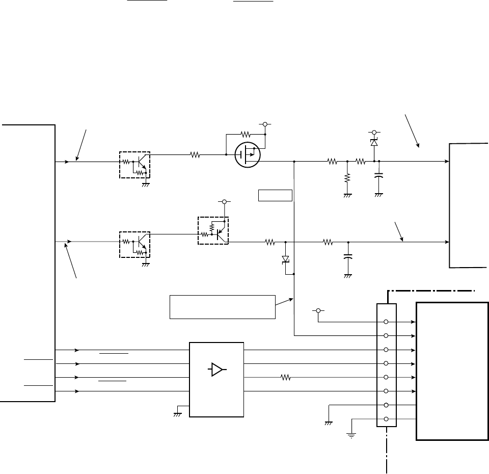
Chapter 2 Operating Principles
2-2. Operation of Control Parts
CL-S700/CL-S703/CL-S700R 2-32
(2) Head driver
The head driver is incorporated in the “Unit, Head”.
During printing, pin 116 (HDVON) of U14 (Custom IC) goes to "High", and Q2 and Q1 turn ON.
Thus +24V is supplied to the thermal head (“Unit, Head”).
The print data is sent from U14 (Custom IC) to the head driver in the thermal head.
The signals HD1 to 4, HDSTB, HDCLK and HDLAT (pins 109 to 113, 108, 115 and 107 of U14)
are sent to the thermal head.
According to the print data (HD1 to 4), the selected thermal elements are heated and the
melted ink makes dots on media (or dots are printed on thermal transfer paper).
The width of heating pulse applied to a thermal element varies with the head temperature to
keep the printing density constant.
J3
Thermal
Head
5-8,21-25
1-4,26-30
HEADSTB
HEADCLK
HEADD1-4
HEADLAT
+5V
10,12,14,17
13
U14
Custom IC
HDLTH 107
HDSTB 108
HDCLK 115
HDATA1-4
109-113
HDVON
HCVON
HDVON
116
HCVON 117
+24V
R93
R94 Q1
Q2
Q29
R99
VHEAD
DTC114EM
D2
2SJ505S
D1
+3.3V
U1 CPU
R100
R95
R97
R96
Head supply voltage ON/OFF
Thermal element abnormality check ON
Head power supply monitoring
Thermal element abnormality check
[Main PCB]
When driving: +24V
When checking: +3.3V
HD1-4
HDSTB
HDCLK
HDLAT 16
11
13
2,4,6,8
5
9
7
18,16,
14,12
16
18
9,15
Q3
+3.3V
DTA114EM
DTC114EM
C61
C62
74HCT244
1,19
R101
11
HDTHM1
VHEADMON
HEADRES
ANI4
9
ANI5
10
A1-4 Y1-4
A5 Y5
A6 Y6
A7 Y7
U15A
OE
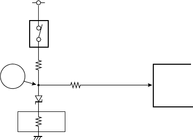
Chapter 2 Operating Principles
2-2. Operation of Control Parts
2-33 CL-S700/CL-S703/CL-S700R
Thermal resistance check:
When the printer is turned ON, the thermal resistance check is conducted. If any fault is found,
the ERROR LED blinks and the LCD displays “Alarm Head Check” on the operation panel.
During the thermal resistance check, pin 117 (HCVON) of U14 (Custom IC) goes to "High", and
Q29 and Q3 turn ON. Thus, +3.3V is supplied to the thermal head, instead of +24V.
The following is a simplified circuitry under checking, where Q3 turns ON and a thermal
element "R" is selected. The voltage at point “A” becomes the value divided by R99 and R. The
CPU monitors this voltage at pin 10 (HEADRES), and check if the voltage is in the allowable
range or not. (If R is open, the voltage at point “A” will be about +3.3V.)
Every thermal element is successively checked in this way.
+3.3V
U1
CPU
R99
R
A
R: Resistance of a thermal element in the thermal head
Q3
Thermal head
R100
HEADRES ANI5
10
D2
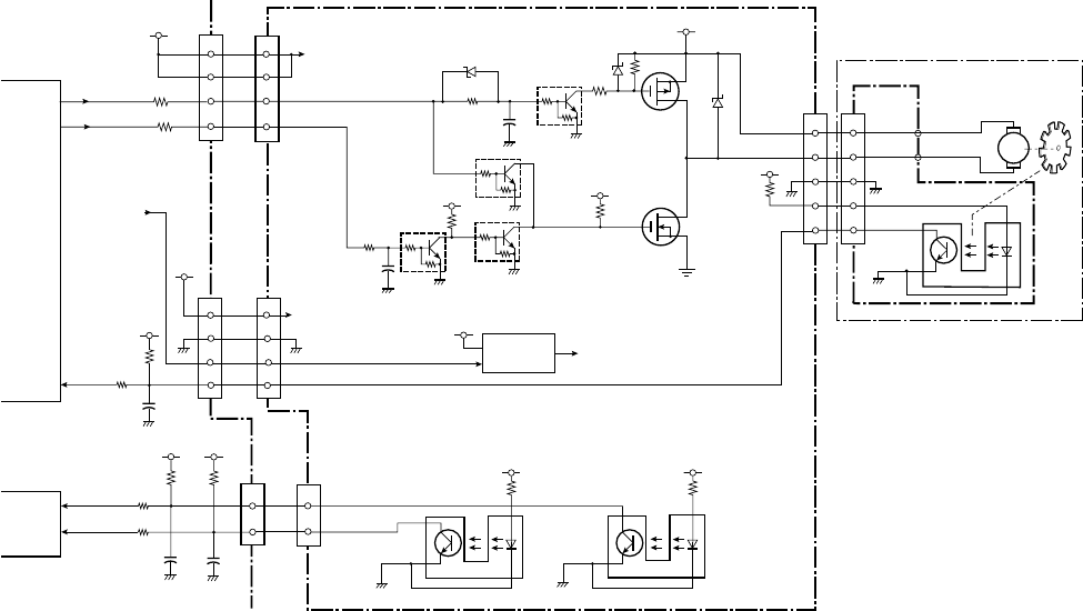
Chapter 2 Operating Principles
2-2. Operation of Control Parts
CL-S700/CL-S703/CL-S700R 2-34
(3) Rewinder motor driver (CL-S700R only)
This is a driving circuit to drive the rewinder motor (DC motor). The following illustration shows
a simplified circuit.
Rewinder motor ON/OFF status is controlled by DCMTR1 and DCMTR0 signals sent from pins
35 and 40 of U1 (CPU).
Motor ON: DCMTR1=L and DCMTR0=H
Motor OFF (free): DCMTR1=L and DCMTR0=L
Braking: DCMTR1=H (DCMTR0=L/H)
When DCMTR1 signal is “Low”, Q502 turns OFF and Q501 turns OFF. When DCMTR0 signal
is “High”, Q506 turns ON, Q505 turns OFF and, if Q503 is OFF (DCMTR1 signal is “Low”),
Q504 turns ON and the rewinder motor is turned.
Rewinder Full detection:
The form sensor (photo interrupters PS501 and PS502) on the “SA, Rewinder PCB” is used to
detect the diameter of wound liner (or the amount of liner) at the flange in the following four
stages. As the diameter increases, the Measure Flap Plate turns backward and engages with
PS501 and PS502.
1st stage: PS501: ON, PS502: OFF
2nd stage: PS501: ON, PS502: ON
3rd stage: PS501: OFF, PS502: ON
4th stage (Full): PS501: OFF, PS502: OFF
The 1st to 3rd stages are used to control the rewinder motor speed as mentioned on the next
page. The 4th stage is the Full state.
The outputs of PS501 and PS502 are fed to pins 84 (HPSENS0) and 85(HPSENS1) of U14
(Custom IC). When the Measure Flap Plate engages PS501/PS502, the light emitted from the
LED is blocked by the plate and PS501/PS502 turns ON and pin 84/85 becomes “High”.
J504
3
2
J502
[SA, Rewinder Motor]
J701
2
3
M
Rewinder Motor
+3.3V
R163
R165
3
[Main PCB]
MTENC
U1 CPU
P72 176 C99
2
J16
5
6
7
Blade
1
3
5
6
7
+5.0V
R512
Q501
2SJ668
+RW
R505
D503
Q504
2SK4033
Q505
DTC114EM
Q502
DTC114EM
+5.0V
R507
R504
C506
+5.0V
R508
7
J501
7
6
J15
DCMTR1
DCMTR0
R506
Q503
DTC114EM
MTENC
35
DCMTR1
DCMTR0
40
PCS7
PCS4
R157
R156
4
+5.0V
4
+5.0V
11
MTREF
6
+24.0V
+24.0V
+24.0V
U501
Switching Regulator
+RW
[Rewinder PCB]
D502
DTC114EM
Q506
C507
R509
D504
ADJ
R510
+5.0V
PS501
R511
+5.0V
PS502
8
J501
8
9
J15
SW6
9
MTREF
(+RW Control)
U14
Custom IC
+3.3V
R153
R159
84
SW5
+3.3V
R154
R158
HPSENS0
85
C97
J15
C96
HPSENS1
1
1
22
HPSENS0
HPSENS1
PS701

Chapter 2 Operating Principles
2-2. Operation of Control Parts
2-35 CL-S700/CL-S703/CL-S700R
When Full state (PS501: OFF, PS502:OFF) is detected, rewinding operation stops, and the
ERROR LED blinks and the LCD displays “Error Rewinder Full” on the operation panel.
Liner rewinding operation:
The rewinder motor turns to wind up the liner. During motor running, the blade of the motor
turns and the intermittent pulse is output from the photo interrupter PS701 of the “SA,
Rewinder Motor” to pin 176 (MTENC) of U1 (CPU).
The rewinder motor speed should vary according to the diameter of the wound liner to nearly
keep the winding speed constant. The rewinder motor speed is controlled by checking the
ON/OFF status of PS501 and PS502. That is, the rewinder motor speed is high for small
diameter and it is low for large diameter. This is accomplished by the MTREF signal sent to
U501 (Switching regulator) that produces +RW power supply for the rewinder motor. +RW can
be changed by changing the level of the MTREF signal. (Higher +RW turns the rewinder motor
faster.)
SA, Rewinder Flange
SA, Rewinder Motor
(Photo Interrupter)
(Blade)
Liner
Plate, Measure Flap
SA, Rewinder Flange
PS501PS502
SA, Rewinder
PCB
Liner
Error: Rewinder Full
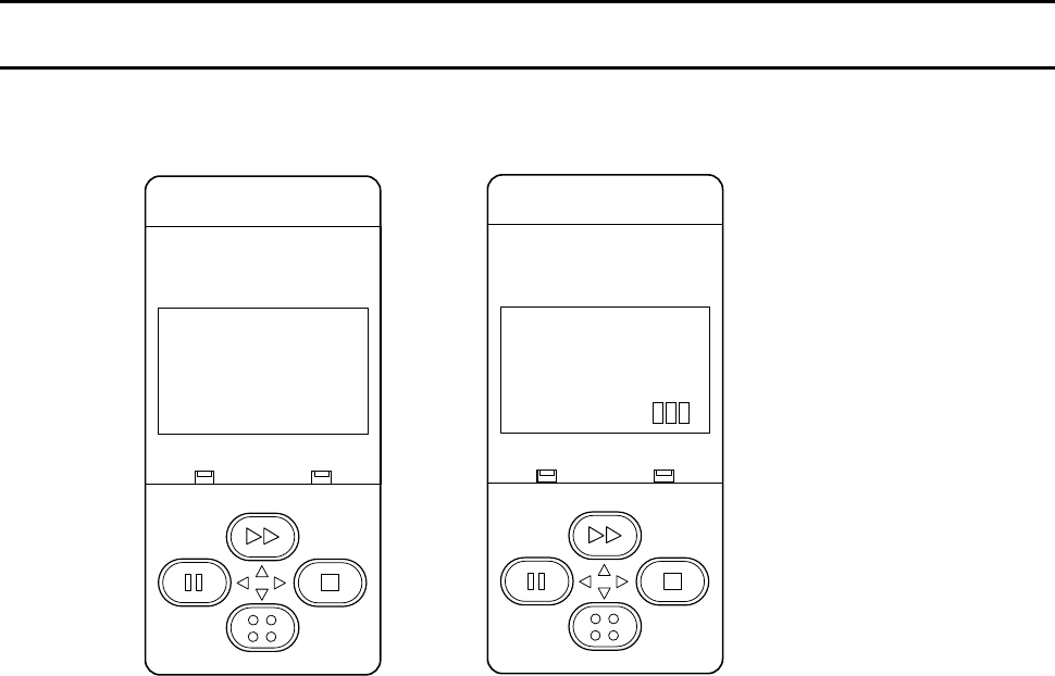
Chapter 2 Operating Principles
2-3. Operation Panel
CL-S700/CL-S703/CL-S700R 2-36
2-3. Operation Panel
Operation panel is located on the left/front side of the printer.
Operation panel consists of 4 keys, 6 LEDs and 1 LCD.
CL-S700/CL-S703 CL-S700R
2-3-1. External view
(1) Keys
There are 4 keys, [MENU], [PAUSE], [FEED] and [STOP]. The function name on the key is
selected when the key is pressed.
(2) LEDs
There are 6 LEDs; POWER LED, ERROR LED and 4 LEDs for keys. The LEDs light up or
blink to indicate printer status, setting modes, or error conditions.
POWER LED: Lights up when power is turned on. (green)
ERROR LED: Blinks when an error occurs. (orange)
LEDs for keys: Light up when power is turned on to illuminate keys.
(3) LCD (Liquid Crystal Display)
The LCD is a 128 x 64 dots display using STN (Super-Twisted Nematic) display system.
It displays printer statuses including alarm statuses, menus and its operation guide, etc.
POWER ERROR
FEED
STOP
MENU
PAUSE
On Line
Ready
POWER ERROR
FEED
STOP
MENU
PAUSE
On Line
Ready
Rewind
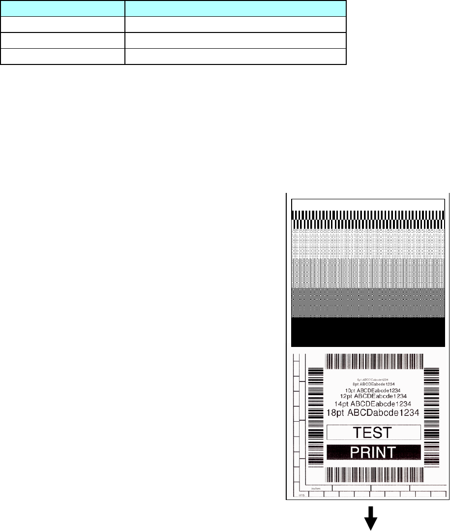
Chapter 2 Operating Principles
2-3. Operation Panel
2-37 CL-S700/CL-S703/CL-S700R
2-3-2. Menu setup mode
You can set the menu according to your requirements.
To enter menu setup mode, press the [MENU] key while “On Line Ready” is displayed on the LCD.
For details, refer to the User’s Manual.
2-3-3. Test mode
The following Test modes are available:
Operation Description
[FEED] + “Power ON” Enters self print mode.
[STOP] + “Power ON” Enters hex dump mode.
[MENU] + “Power ON” Enters menu list printing mode.
(1) Self print mode
You can check the printing quality by printing the built-in self print pattern.
This function is convenient to obtain optimum printing while adjusting the media thickness with
the Media Thickness Adjustment screw and media width with the Media Width Adjustment
knob.
For label (prints 2 labels):
1. While pressing and holding the [FEED] key, turn on
the power.
2. Wait until the POWER LED turns on and the LCD
indicates “Self Print Mode” “Label Media”, and then
release the [FEED] key.
The printer enters self print mode and the label is fed.
Self test printing is made for two labels, and then
printing stops.
3. To repeat self test printing, press the [FEED] key
again.
To exit from self print mode: Turn off the power.
For continuous media:
1. While pressing and holding the [FEED] key, turn on
the power.
2. Wait until the POWER LED turns on and the LCD
changes from “Self Print Mode” “Label Media” to “Cont.
Media”, and then release the [FEED] key.
The printer enters self print mode and the label is fed
for self test printing. After printing it stops.
3. To repeat self test printing, press the [FEED] key again.
To exit from self print mode: Turn off the power.
Media feed direction
<Example of CL-S700/CL-S700R>
[Print pattern in self print mode]

Chapter 2 Operating Principles
2-3. Operation Panel
CL-S700/CL-S703/CL-S700R 2-38
(2) Hex dump mode
You can print the data in the receive buffer in the hexadecimal form.
For label:
1. While pressing and holding the [STOP] key, turn on the power.
2. Wait until the POWER LED turns on and the LCD indicates “Hex Dump Mode” “Label
Media”, and then release the [STOP] key.
The printer enters hex dump mode and, when print data is sent to the printer, hex dump
printing starts.
To exit from hex dump mode: Turn off the power.
For continuous media:
1. While pressing and holding the [STOP] key, turn on the power.
2. Wait until the POWER LED turns on and the LCD changes from “Hex Dump Mode” “Label
Media” to “Cont. Media”, and then release the [STOP] key.
The printer enters hex dump mode and, when print data is sent to the printer, hex dump
printing starts.
To exit from hex dump mode: Turn off the power.
DUMP LIST
02 40 30 31 30 30 0D 02 60 30 30 32 30 0D 02 4C .M0100..c0020..L
44 31 31 0D 31 30 30 30 30 30 30 30 30 30 31 30 D11.100000000010
30 30 31 30 31 32 33 34 35 36 37 38 39 3A 3B 3C 0010123456789:;<
[Dump list example]

Chapter 2 Operating Principles
2-3. Operation Panel
2-39 CL-S700/CL-S703/CL-S700R
(3) Menu list print mode
You can print the list of machine information and current menu settings.
1. While pressing and holding the [MENU] key, turn on the power.
The POWER LED turns on and the LCD indicates “Print Settings”, and then automatically
print starts.
The printer prints the list of machine information and current menu settings, and then
enters menu setup mode for further menu operation.
To exit from menu list print mode: In Main menu, press the [PAUSE] (W) key.
Machine Information
Model Number : CL-S700
Boot Version : ****
ROM Version : ********
ROM Date(DD//MM//YY) : XX/XX/XX
ROMCheck Sum : ****
Head Check : OK
Print Counter : 0002.234 km
Service Counter : 0002.234 km
Sensor Monitor : 1.50 V
Option Interface : None
Current Menu Settings
[Page Setup Menu]
Print Speed : 7 IPS
Print Darkness : 12
Darkness Adjust : 00
Print Method : Thermal Transfer
Continuous Media Length : 4.00 inch
Vertical Position : 0.00 inch
Horizontal Shift : 0.00 inch
Vertical Image Shift : 0.00 inch
Sensor Select : Rear Adj Sensor
Media Sensor : See Through
Small Media Adjustment : Off
Small Media Length : 1.00 inch
Symbol Set : PM
[System Setup Menu]
Sensor Level : 1.7 V
Paper End Level : 2.80 V
Error Reporting : On Printing
Cover Open Sensor : Off
Buzzer Select : On
Metric/Inch : Inch
Max Media Length : 10.00 inch
Setting Lock : Off
Keyboard Lock Off
Control Code : STD
Emulation Select : DM4
[After Print Menu]
AutoConfigure : On
Function Select : Tear
Cutter Action : Backfeed
Paper Position : 0.00 inch
Menu Key Action : Enters Menu
[Interface Menu]
RS-232C Baud rate : 9600
RS-232C Parity : None
RS-232C Length : 8 bit
RS-232C Stop bit : 1 bit
RS-232C X-ON : Yes
IEEE 1284 : On
USB Device Class : Printer
USB VCOM Protocol : Auto
<Example of Datamax® emulation selected (CL-S700)>
Note:
Citizen continually enhances
its printers with new options
and settings based on our
customer’s requests. Extra or
changed menu items may
appear on the print out in some
cases.

Chapter 2 Operating Principles
2-3. Operation Panel
CL-S700/CL-S703/CL-S700R 2-40
2-3-4. Factory/Service mode
Factory mode and Service mode are available for maintenance work,
Factory mode:
You can change the factory-set items such as logical shift of the sensor or head.
Service mode:
You can perform checks such as head check and service counter value that shows the media
length printed.
In this section, the followings are explained.
• How to enter Factory/Service Mode
• How to print the Factory Mode Settings menus
• How to change the settings in Factory mode
• How to operate service menu in Service mode
(1) How to enter Factory/Service Mode
To enter Factory/Service mode, perform the following operation.
• While pressing and holding the [MENU], [FEED] and [STOP] keys, turn on the printer.
Then, the following is displayed on the LCD.
Key function in Factory/Service mode:
[FEED] (S) Returns to previous item, or the value is incremented/changed.
[MENU] (T) Goes to the next item, or the value is decremented/changed.
[PAUSE] (W) Resets the printer, or exits from the current menu.
[STOP] (X) Acts as the Enter key.
W X
Main Menu
Factory Setup
Exit
Enter
S T
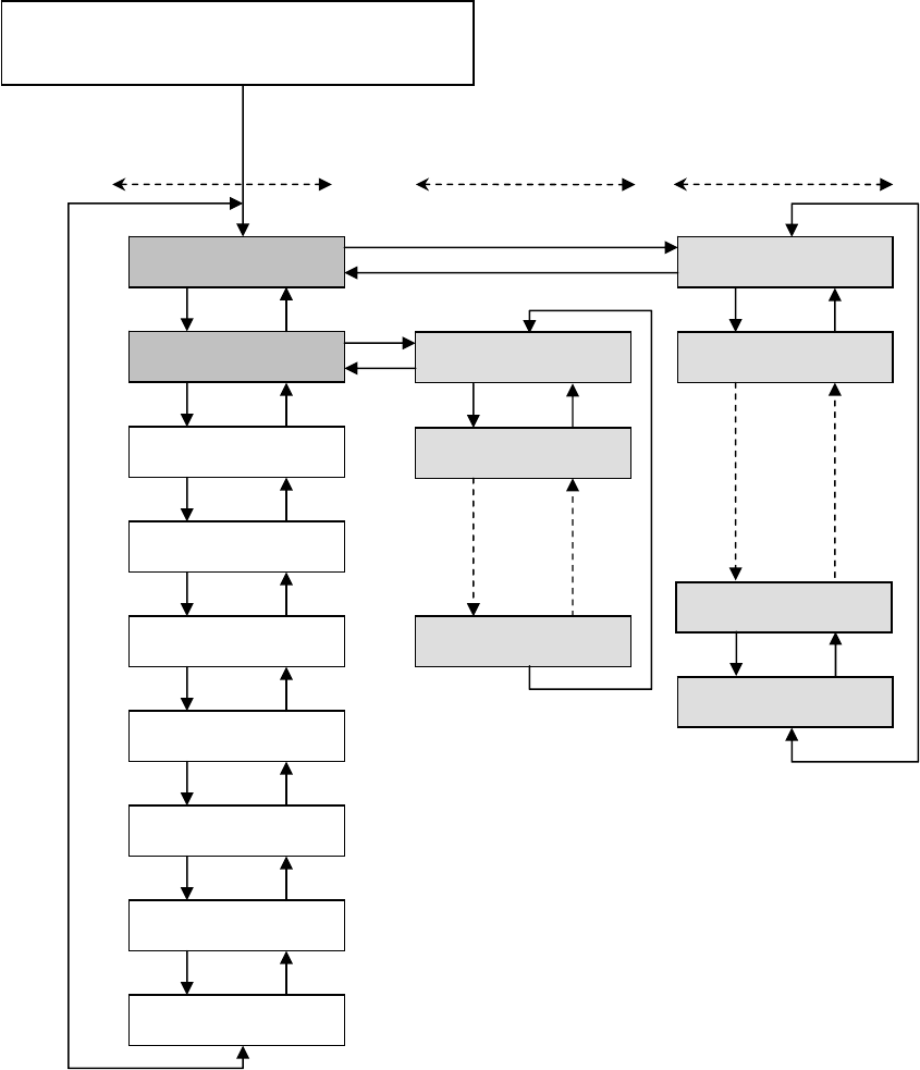
Chapter 2 Operating Principles
2-3. Operation Panel
2-41 CL-S700/CL-S703/CL-S700R
The following diagram shows the menu transition in Factory/Service mode.
To exit from Factory/Service mode:
In Main menu, press the [PAUSE] (W) key.
While pressing the [MENU], [FEED] and
[STOP] keys, turn on the printer.
Factory Setup
Service Mode
TS
Page Setup
TS
System Setup
TS
After Print
TS
Interface
TS
Machine Info
TS
Test Mode
TS
Global Config
TS
Main menu
Sens Vol Adj
Init Fix-Thru
TS
USB Serial Num
TS
Submenu
(Factory mode)
Head Check
ROM Check
TS
X
W
Service Counter
TS
X
W
Submenu
(Service mode)
Parallel ErrOut
Chapter 2 Operating Principles
2-3. Operation Panel
CL-S700/CL-S703/CL-S700R 2-42
(2) How to print the Factory Mode Settings menus
You can print the current factory mode setting values in the following two ways.
Method 1:
While pressing and holding all keys ([MENU], [FEED], [STOP] and [PAUSE]), turn on the
power.
The current factory mode setting values are printed, and then the printer enters the Factory
mode.
To exit from the Factory mode: Press the [PAUSE] (W) key.
Method 2
Enter the Factory/Service mode and print the configuration settings.
1) Enter the Factory/Service mode by turning on the power while pressing and holding the
[MENU], [FEED] and [STOP] keys. (Refer to “(1) How to enter Factory/Service Mode”
mentioned earlier.)
2) Press the [MENU] (T) or [FEED] (S) key until “Test Mode” main menu appears.
3) Press the [STOP] (X) key to enter the Test Mode.
4) Press the [MENU] (T) or [FEED] (S) key until “Print Pattern” submenu appears.
5) Press the [STOP] (X) key to enter the Print Pattern submenu.
6) Press the [MENU] (T) or [FEED] (S) key and select “Current Config”.
7) Press the [STOP] (X) key to print the configuration settings.
The current factory mode setting values are printed.
To exit from menu mode:
Press the [PAUSE] (W) key until the printer exits from the “Test Mode” main menu.
Chapter 2 Operating Principles
2-3. Operation Panel
2-43 CL-S700/CL-S703/CL-S700R
[Print sample] Machine Information
Model Number : CL-S700
Boot Version : ****
ROM Version : ********
ROM Date(DD//MM//YY) : XX/XX/XX
ROMCheck Sum : ****
Head Check : OK
Print Counter : 0002.234 km
Service Counter : 0002.234 km
Sensor Monitor : 1.50 V
Option Interface : None
Factory Mode Settings
Fix Through Sensor Pos. : 0 dot
Fix Reflect Sensor Pos. : 0 dot
Adj Through Sensor Pos. : 0 dot
Adj Reflect Sensor Pos. : 0 dot
Machine Tear Position : 0 dot
Machine Cut Position : 0 dot
Machine Peel Position : 0 dot
Machine Horizontal Pos. : 8 dot
AutoCal Mode : On
Fix Through Sensor : 0.0 V
Fix Reflect Sensor : 0.0 V
Adj Through Sensor : 0.0 V
Adj Reflect Sensor : 0.0 V
Fix Through Cal Level : 2.30 V
Fix Reflect Cal Level : 2.10 V
Fix SensNone Cal Level : 2.05 V
Adj Through Cal Level : 2.30 V
Adj Reflect Cal Level : 2.10 V
Adj SensNone Cal Level : 2.05 V
Double Heat Menu : Off
PowerOn Head Check : On
Head Check Start Pos. : Dot 1
Head Check Stop Pos. : Dot 848
Head Error Print : No
Max Page Length : 32 inch
Ribbon End Detection : Normal
Void to TOF : Off
Reverse Media Length : 0.00 inch
Paper End Sensor : On
Parallel Error Output : On
Auto Online : Off
Auto Online Delay : 2 sec
Top Form Sensing : On
USB Serial Number : Off
Current Menu Settings
[Page Setup Menu]
Print Speed : 7 IPS
Print Darkness : 12
Darkness Adjust : 00
Print Method : Thermal Transfer
Continuous Media Length : 4.00 inch
Vertical Position : 0.00 inch
Horizontal Shift : 0.00 inch
Vertical Image Shift : 0.00 inch
Sensor Select : Rear Adj Sensor
Media Sensor : See Through
Small Media Adjustment : Off
Small Media Length : 1.00 inch
Symbol Set : PM
<Example of Datamax® emulation selected (CL-S700)>
Submenus for maintenance only
Chapter 2 Operating Principles
2-3. Operation Panel
CL-S700/CL-S703/CL-S700R 2-44
[System Setup Menu]
Sensor Level : 1.7 V
Paper End Level : 2.80 V
Error Reporting : On Printing
Cover Open Sensor : Off
Buzzer Select : On
Metric/Inch : Inch
Max Media Length : 10.00 inch
Setting Lock : Off
Keyboard Lock Off
Control Code : STD
Emulation Select : DM4
[After Print Menu]
AutoConfigure : On
Function Select : Tear
Cutter Action : Backfeed
Paper Position : 0.00 inch
Menu Key Action : Enters Menu
[Interface Menu]
RS-232C Baud rate : 9600
RS-232C Parity : None
RS-232C Length : 8 bit
RS-232C Stop bit : 1 bit
RS-232C X-ON : Yes
IEEE 1284 : On
USB Device Class : Printer
USB VCOM Protocol : Auto
<Example of Datamax® emulation selected (CL-S700) - continued>
Note:
Citizen continually enhances
its printers with new options
and settings based on our
customer’s requests. Extra or
changed menu items may
appear on the print out in some
cases.
Chapter 2 Operating Principles
2-3. Operation Panel
2-45 CL-S700/CL-S703/CL-S700R
(3) How to change the settings in Factory mode
- In Factory mode, DO NOT change the factory-set values unless you need to change
them, since there are essential items related to printing accuracy, etc.
- Do not turn OFF the power of the printer until you finish the adjustment. If it is
turned OFF, you need to repeat the adjustment from the beginning.
- The value adjusted here is retained until you change it with the same
procedure. Even if you perform initialization by selecting “Test Mode” main
menu, “Factory Default” submenu and “Yes”, the changed value is not
returned to the initial value set at the factory.
(3-1) Submenu table in Factory mode
The following table shows the submenus of “Factory Setup” main menu.
*1 “[Factory Mode Settings Menu name]” in “Submenu Name” column shows the name
that will be printed in “Factory Mode Settings”. (Refer to “(2) How to print the Factory
Mode Settings menus”.)
*2 “+” shows that the object electrically moves forward/rightward. “-“ shows that the object
electrically moves backward/leftward. 8 dots correspond to 1 mm (203 dots correspond
to 1”).
Submenu Name
[Factory Mode Settings
Menu name]
Adjustable Value
(Default Value) Description
Sens Vol Adj
Displays the level of each media sensor.
Init Fix-Thru
Performs calibration of the transparent sensor
sensitivity (fixed type). For details, refer to “3-6-1
(2) Sensor sensitivity adjustment (Factory
mode)” in Chapter 3.
Init Fix-Refl
Performs calibration of the reflective sensor
sensitivity (fixed type). For details, refer to “3-6-1
(2) Sensor sensitivity adjustment (Factory mode”
in Chapter 3.
Init Adj-Thru
Performs calibration of the transparent sensor
sensitivity (adjustable type). For details, refer to
“3-6-1 (2) Sensor sensitivity adjustment (Factory
mode” in Chapter 3.
Init Adj-Refl
Performs calibration of the reflective sensor
sensitivity (adjustable type). For details, refer to
“3-6-1 (2) Sensor sensitivity adjustment (Factory
mode” in Chapter 3.
Caution

Chapter 2 Operating Principles
2-3. Operation Panel
CL-S700/CL-S703/CL-S700R 2-46
Submenu Name
[Factory Mode Settings
Menu name]
Adjustable Value
(Default Value) Description
Fix-Thru Pos
[Fix Through Sensor Pos.]
-256 to +256 dot
(+000 dot)
Electrically shifts the position of transparent
sensor (fixed type) back and forth.
(-32 to +32 mm, -1.26 to +1.26”)
Fix-Refl Pos
[Fix Reflect Sensor Pos.]
-256 to +256 dot
(+000 dot)
Electrically shifts the position of reflective sensor
(fixed type) back and forth.
(-32 to +32 mm, -1.26 to +1.26”)
Adj-Thru Pos
[Adj Through Sensor Pos.]
-256 to +256 dot
(+000 dot)
Electrically shifts the position of transparent
sensor (adjustable type) back and forth.
(-32 to +32 mm, -1.26 to +1.26”)
Adj-Refl Pos
[Adj Reflect Sensor Pos.]
-256 to +256 dot
(+000 dot)
Electrically shifts the position of reflective sensor
(adjustable type) back and forth.
(-32 to +32 mm, -1.26 to +1.26”)
Mach Tear Pos
[Machine Tear Position]
-256 to +256 dot
(+000 dot)
Electrically shifts the tear off position back and
forth. (-32 to +32 mm, -1.26 to +1.26”)
Mach Cut Pos
[Machine Cut Position]
-256 to +256dot
(+000 dot)
Electrically shifts the cutting position back and
forth. (-32 to +32 mm, -1.26 to +1.26”) (Optional)
Mach Peel Pos
[Machine Peel Position]
-256 to +256dot
(+000 dot)
Electrically shifts the peel position back and
forth. (-32 to +32 mm, -1.26 to +1.26”) (Optional)
Mach Hor Pos
Machine Horizontal Pos.]
-16 to +32dot
(+008 dot)
Electrically shifts the head position to the right or
left side.
(-2 to +4 mm, -0.08 to +0.16”)
Auto Cal Mode
[AutoCal Mode]
On/Off
(On)
Automatically controls the light amount of each
media sensor.
Fix-Thru LED
[Fix Through Sensor]
0.0 to 3.3V
(0.0 V)
This menu is effective when “Auto Cal Mode” is
set to OFF. The light amount emitted from the
transparent sensor (fixed type) can be changed
manually.
Larger value emits larger amount of light.
Fix-Refl LED
[Fix Reflect Sensor]
0.0 to 3.3V
(0.0 V)
This menu is effective when “Auto Cal Mode” is
set to OFF. The light amount emitted from the
LED of the reflective sensor (fixed type) can be
changed manually.
Larger value emits larger amount of light.
Adj-Thru LED
[Adj Through Sensor]
0.0 to 3.3V
(0.0 V)
This menu is effective when “Auto Cal Mode” is
set to OFF. The light amount emitted from the
transparent sensor (adjustable type) can be
changed manually.
Larger value emits larger amount of light.
Adj-Refl LED
[Adj Reflect Sensor]
0.0 to 3.3V
(0.0 V)
This menu is effective when “Auto Cal Mode” is
set to OFF. The light amount emitted from the
LED of the reflective sensor (adjustable type)
can be changed manually.
Larger value emits larger amount of light.

Chapter 2 Operating Principles
2-3. Operation Panel
2-47 CL-S700/CL-S703/CL-S700R
Submenu Name
[Factory Mode Settings
Menu name]
Adjustable Value
(Default Value) Description
Fix-Thru Level
[Fix Through Cal Level]
0.01 to 3.30V
(2.30 V)
Performs sensitivity adjustment of the front fixed
sensor for Media Sensor menu “See Through”.
The amount of light received is set to “2.30V”.
Fix-Refl Level
[Fix Reflect Cal Level]
0.01 to 3.30V
(2.10 V)
Performs sensitivity adjustment of the front fixed
sensor for Media Sensor menu “Reflect”. The
amount of light received is set to “2.10V”.
Fix-None Level
[Fix SensNone Cal Level]
0.01 to 3.30V
(2.05 V)
Performs sensitivity adjustment of the front fixed
sensor for Media Sensor menu “None”. The
amount of light received is set to “2.05V”.
Adj-Thru Level
[Adj Through Cal Level]
0.01 to 3.30V
(2.30V)
Performs sensitivity adjustment of the adjustable
sensor for Media Sensor menu “See Through”.
The amount of light received is set to “2.30V”.
Adj-Refl Level
[Adj Reflect Cal Level]
0.01 to 3.30V
(2.10 V)
Performs sensitivity adjustment of the adjustable
sensor for Media Sensor menu “Reflect”. The
amount of light received is set to “2.10V”.
Adj-None Level
[Adj SensNone Cal Level]
0.01 to 3.30V
(2.05 V)
Performs sensitivity adjustment of the adjustable
sensor for Media Sensor menu “None”. The
amount of light received is set to “2.05V”.
Peel Sens Level
0.01 to 3.30V
(1.50 V)
Sets the threshold value for the peel sensor.
Cont Paper Sens
Through/Reflect
(Reflect)
When continuous media is used, selects the
sensor type to be used for detecting paper end.
Dbl Heat Menu
[Double Heat Menu]
On/Off
(Off)
Sets whether to display the menu of "Double
Heat".
PwrOn Head Chk
[Power On Head Check]
On/Off
(On)
Sets whether to perform head check at power
ON or not.
Head Chk Start
[Head Check Start Pos.]
Dots 001 to 848
(Dot 001)
Designates the start dot for head check.
Head Chk Stop
[Head Check Stop Pos.]
Dots 001 to 848
(Dot 848)
Designates the end dot for head check.
Rbn End Detect
[Ribbon End Detection]
Normal/Slow
(Normal)
Sets the ribbon end detection time.
Parallel ErrOut On/Off
(On)
Select whether to activate the Fault signal of
parallel interface at the time of error occurrence.
USB Serial Num
[USB Serial Number]
On/Off
(Off)
Select whether to send the serial number to the
host when operating the printer through the USB
interface.

Chapter 2 Operating Principles
2-3. Operation Panel
CL-S700/CL-S703/CL-S700R 2-48
(3-2) Setting submenu in Factory mode
In Factory mode, there are 2 types of submenus.
• Value setting type
• Option selection type
Procedure:
1. Enter Factory/Service mode by turning on the power while pressing and holding the
[MENU], [FEED] and [STOP] keys.
“Factory Setup” main menu appears.
2. In “Factory Setup” main menu, press the [STOP] (X) key to enter Factory Setup mode.
The first submenu “Sens Vol Adj.” appears.
3. Press the [MENU] (T) or [FEED] (S) key until “Adj-Thru Pos” submenu (example)
appears.
4. Press the [STOP] (X) key to select that submenu.
The current value is shown on the LCD.
5. Press the [MENU] (T) or [FEED] (S) key to increase or decrease the value (or select
a desired option).
In this example, the position of transparent sensor (adjustable type) will be electrically
moved back (-) and forth (+).
6. Press the [STOP] (X) key to save the set value in the printer.
7. Press the [PAUSE] (W) key to return to “Factory Setup” menu. (To set other submenu,
repeat from Step 2.)
8. Press the [PAUSE] (W) key once again.
The changed value is stored in the printer and the printer is turned OFF and then ON
for normal operation.
W X
Position
+000 dots
Exit
Enter
S T

Chapter 2 Operating Principles
2-3. Operation Panel
2-49 CL-S700/CL-S703/CL-S700R
(4) How to operate submenus in Service mode
(4-1) Submenu table in Service mode
The following table shows the submenus of “Service Mode” main menu.
Submenu Name Value Description
Head Check Checks the number of defective thermal elements
and displays it. If no defective thermal element is
found, “0000” will be displayed.
Example: PASS
0000dots
ROM Check
Performs ROM checksum test, and displays the
check result (OK or NG) and the checksum value.
Example: PROGRM
OK 4F4E.
RAM Check
Performs RAM capacity check and displays the
check result.
Example: DRAM
OK 16384KByte
Motor Feed Performs motor feed check.
Print Counter
Displays the total printed length since the printer is
firstly used.
Example: Length
1234.567Km
Service Counter
Displays the service counter length in Km since you
reset it last.
Example: Length
0123.456Km
To clear the service counter, press the [Enter] (X)
key.

Chapter 2 Operating Principles
2-3. Operation Panel
CL-S700/CL-S703/CL-S700R 2-50
(4-2) Submenu operation in Service mode
The submenu operation procedures in Service mode are explained here. The submenus
other than “Service Counter” and the “Service Counter” submenu are separately explained.
Operation procedure for submenus other than “Service Counter”:
1. Enter Factory/Service mode by turning on the power while pressing and holding the
[MENU], [FEED] and [STOP] keys.
“Factory Setup” main menu appears.
2. Press the [MENU] (T) or [FEED] (S) key until “Service Mode” main menu appears.
3. Press the [STOP] (X) key to enter Service mode.
4. Press the [MENU] (T) or [FEED] (S) key until the desired submenu (e.g. “Head
Check”) appears.
5. Press the [STOP] (X) key to select that submenu.
* For submenus “ROM Check”, “RAM Check”, and “Print Counter”, the result is displayed
and further operation is not necessary.
* For submenu “Head Check”, the following screen appears and prompts you whether to
perform the head check or not.
* For submenu “Motor Feed”, the following screen appears and prompts you whether to
feed media forward or backward.
[When “Head Check” is selected] [When “Motor Feed” is selected]
6. Press the [MENU] (T) or [FEED] (S) key and select “Yes” (when “Head Check” is
selected) or “Forward”/”Back” (when “Motor Feed” is selected).
7. Press the [STOP] (X) key to perform the selected item.
* When “Head Check” is selected, the number of defective dots of the thermal head is
displayed.
* When “Motor Feed” is selected, the PF motor turns to feed media forward or backward.
[When “Head Check” is selected] [When “Motor Feed” is selected]
8. Press the [PAUSE] (W) key to return to “Service Mode” menu.
9. To check other submenu, repeat from Step 3. Otherwise, turn off the power to
terminate Factory/Service mode.
W X
Service Mode
Head Check
Exit
Enter
S T
W X
PASS
0000dots
Exit
Enter
W X
Check
No
Exit
Enter
S T
WX
Motor Feed
Back
Exit
Enter
ST
WX
Motor Feed
Forward
Exit
Enter
ST
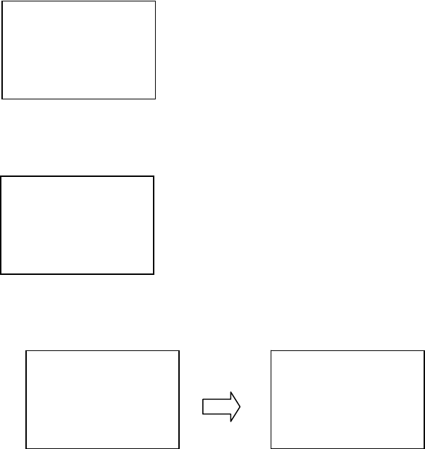
Chapter 2 Operating Principles
2-3. Operation Panel
2-51 CL-S700/CL-S703/CL-S700R
Operation procedure for “Service Counter” submenu:
1. Enter Factory/Service mode by turning on the power while pressing and holding the
[MENU], [FEED] and [STOP] keys.
“Factory Setup” main menu appears.
2. Press the [MENU] (T) or [FEED] (S) key until “Service Mode” main menu appears.
3. Press the [STOP] (X) key to enter Service mode.
4. Press the [MENU] (T) or [FEED] (S) key until “Service Counter” submenu appears.
5. Press the [STOP] (X) key to select “Service Counter” submenu.
Then, the service counter length since the service counter is reset last is displayed.
* To reset the service counter, proceed to the next step. Otherwise, proceed to Step 7.
6. Resetting the service counter:
1) Press the [STOP] (X) key.
2) Press the [MENU] (T) or [FEED] (S) key and select “Yes”.
3) Press the [STOP] (X) key to perform resetting.
7. Press the [PAUSE] (W) key to return to “Service Mode” menu.
8. To check other submenu, repeat from Step 3. Otherwise, turn off the power to
terminate Factory/Service mode.
W X
Service
Counter
Exit
Enter
S T
W X
Length
0123.456 km
Exit
Enter
S T
W X
Reset?
No
Exit
Enter
S T
WX
Reset?
Yes
Exit
Enter
ST
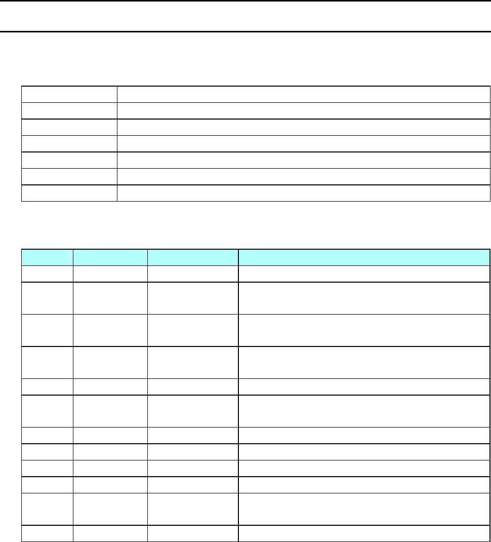
Chapter 2 Operating Principles
2-4. Interface
CL-S700/CL-S703/CL-S700R 2-52
2-4. Interface
2-4-1. Serial Interface
(1) Specifications
System Start/stop asynchronous full duplex communication
Signal level RS-232C
Baud rate 2400, 4800, 9600, 19200, 38400, 57600, 115200 bps
Data length 7 bits, 8 bits
Stop bit 1 bit, 2 bits
Parity Odd, even, none
Connector D-SUB DBR40-251F100 25PIN (ACON)
(2) Signal line and pin assignment
Pin No. Signal Abbr. Signal name Function
1 FG Frame ground Protective grounding
2 TXD Transmit Data Signal line that transmits data from the printer to
the host
3 RXD Receive data Signal line that transmits data from the host to
the printer
4 RTS Request To
Send
Pulled up to +5.4V through 3.3 kΩ
5 NC ------ Not used
6 DSR Data Set Ready Signal line that is active when the host can
interface with the printer
7 SGND Signal ground Signal grounding line
8-13 NC ------ Not used
14 VCC +5V (Factory use only )
15-19 NC ------ Not used
20 DTR Data Terminal
Ready
Signal line that is active when the printer can
interface with the host
21-25 NC ------ Not used
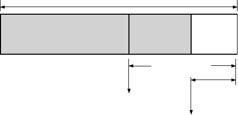
Chapter 2 Operating Principles
2-4. Interface
2-53 CL-S700/CL-S703/CL-S700R
(3) Protocol
XON/XOFF system:
Controlled with the data transmission request signal X-ON (11H) code and the data
transmission stop request signal X-OFF (13H) code.
The conditions for the X-ON code output are as follows:
• When the printer is turned from off-line to on-line.
• When the remaining of receive buffer is 1024 bytes or more after sending X-OFF code.
The conditions for the X-OFF code output are as follows:
• When the remainder of receive buffer is 128 bytes or less.
• When the printer is turned from on-line to off-line.
- When the media end is detected.
- When a printer error occurs.
READY/BUSY System:
DTR signal is controlled with READY ("High")/BUSY ("Low") level.
DTR turns to "High (Ready)" in the following conditions:
• When the printer is in on-line mode, and
• When the remaining buffer is 128 bytes or more.
(After DTR becomes "High", DTR retains "High" until the remaining buffer becomes 1024
bytes or less.)
DTR turns to "Low (Busy)" in the following conditions:
• When the printer is in off-line mode.
• When the remaining buffer is less than 128 bytes.
(After DTR becomes "Low", DTR retains "Low" until the remaining buffer becomes 1024 bytes
or more.)
X-ON code sending
X-OFF code sending
16K bytes
1024 bytes
128 bytes
Received data
0 16K
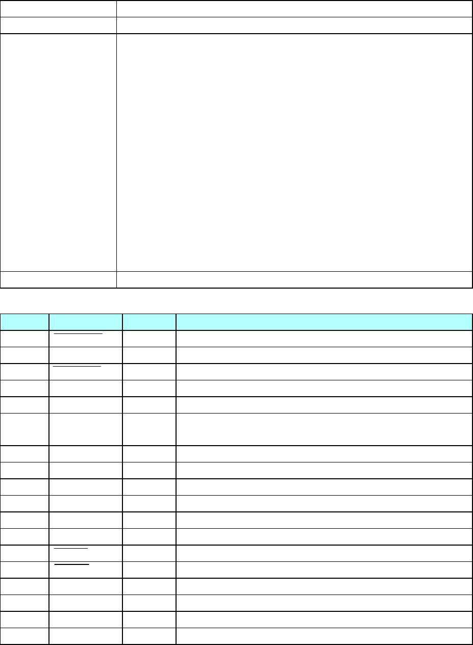
Chapter 2 Operating Principles
2-4. Interface
CL-S700/CL-S703/CL-S700R 2-54
2-4-2. Parallel Interface
(1) Specifications
Transmission system 8-bit parallel data
Receive buffer size 16K bytes
Transmission modes Compatible mode
It is an asynchronous forward channel mode to send the byte width
data from the host to the printer. The interface line of the data is
operated in accordance with signal line definitions of Centronics.
NIBBLE mode
It is an asynchronous reverse channel mode to send the data from
the printer to the host. In Nibble mode, 4-bit data (half byte) is sent at
a time using the 4 status lines (FAULT, SELECT, PE, and BUSY). To
send one complete byte data, the printer sends 2 nibbles (8 bits in
total) to the host. Nibble mode is usually combined with Compatible
mode to create a complete bi-directional channel.
ECP mode
ECP mode permits bi-directional asynchronous data transmission,
and by means of interlock handshake, it does not require the timing
necessary with Compatible mode.
Signal level IEEE1284 compatible
(2) Signal line and pin assignment
Pin No. Signal name I/O Function in Compatible Mode
1 STROBE Input Strobe signal to read in 8-bit data
2-9 DATA0-7 Input 8-bit parallel signal
10 ACKNLG Output 8-bit data request signal
11 BUSY Output Signal specifying printer busy
12 PERROR Output Signal specifying media end
13 SELECT Output Signal specifying if the printer is on-line (printing enabled)
or off-line
14 AUTOFD Input Invalid (ignored)
15 NC --- Not used
16 SGND --- Signal ground
17 FGND --- Frame ground
18 P.L.H Output Peripheral logic high (pulled up to +5V at 1KΩ)
19-30 GND --- Ground for twisted pair return
31 PRIME Input Printer reset
32 FAULT Output Signal specifying printer error
33 GND --- Signal ground
34 NC --- Not used
35 FUSE --- Not used
36 SELECTIN Input Invalid (ignored)
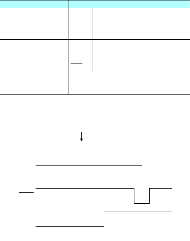
Chapter 2 Operating Principles
2-4. Interface
2-55 CL-S700/CL-S703/CL-S700R
(3) Parallel port status signals when an error occurs
The following table shows the status signal change when an error occurs.
Error Compatible mode
Paper end Busy:
PError:
Select:
Fault:
L → H
L → H
H → L
H → L
Error other than paper end
• Head open
• Other
Busy:
PError:
Select:
Fault:
L → H
L → unchanged
H → L
H → L
Conditions for Busy • Receive buffer full
• Data being read
• Error
(4) Compatible timing specification
[When power is on] (Timing to go on-line)
BUSY
SELECT
Power On
ACK
Reset
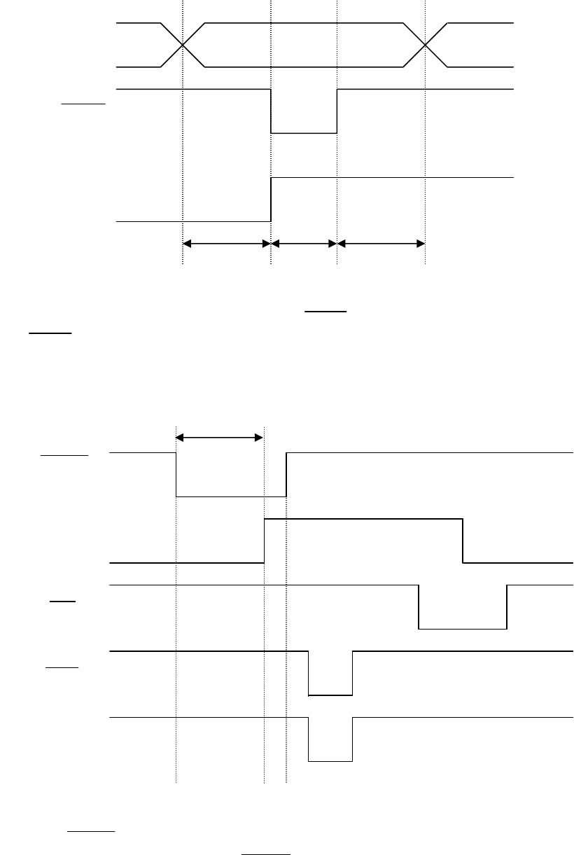
Chapter 2 Operating Principles
2-4. Interface
CL-S700/CL-S703/CL-S700R 2-56
[While receiving data]
Note:
BUSY goes “High” at the falling edge of Strobe, and data is latched at the leading edge of
Strobe.
[While receiving PRIME signal]
Note:
If the PRIME signal width is 10 µsec or less, it is not accepted.
BUSY goes to “High” when the PRIME signal is accepted by the printer.
Data0~7
BUSY
0.5µs 0.5µs 0.5µs
Strobe
BUSY
PRIME
SELECT
10~15µsec or more
Ack
Fault
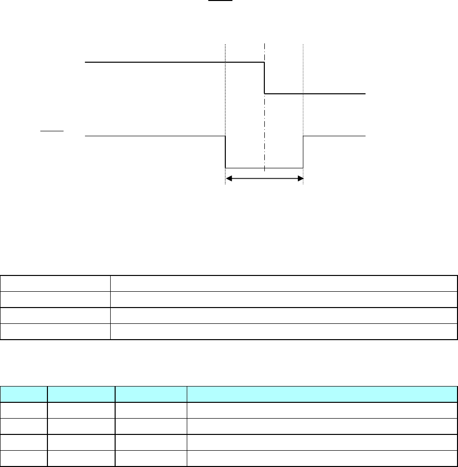
Chapter 2 Operating Principles
2-4. Interface
2-57 CL-S700/CL-S703/CL-S700R
[Timing relationship between BUSY and ACK]
2-4-3. USB Interface
(1) Specifications
Standards Complies with Universal Serial Bus Specification
Transmission speed Compatible with 12Mbps (full speed) transmission
Receive buffer 16K bytes
Connector DUSB DUSB-BRA42-T11 (DDK)
(2) Signal line and pin arrangement
Pin No. Signal code Signal Function
1 VBUS USB power USB power (+5V)
2 D+ Signal line + + signal line
3 D- Signal line - - signal line
4 GND GND GND
About 2 µsec
BUSY
ACK
Center

Chapter 3 Disassembly and Maintenance
CL-S700/CL-S703/CL-S700R
CHAPTER 3
DISASSEMBLY AND MAINTENANCE
Chapter 3 Disassembly and Maintenance
CL-S700/CL-S703/CL-S700R 3-2
Chapter 3 Disassembly and Maintenance
Table of Contents
3-1. Maintenance Precautions ............................................................................................... 4
3-2. Cleaning.......................................................................................................................... 5
3-3. Lubrication/Adhesive Agent ............................................................................................ 5
3-3-1. Lubrication.......................................................................................................... 5
3-3-2. Adhesive Agent ..................................................................................................5
3-4. Maintenance Tools List ................................................................................................... 6
3-5. Disassembly, Reassembly and Lubrication .................................................................... 7
3-5-1. Unit, Head ............................................................................................................ 9
3-5-2. Unit, Roller Platen and Gear, One-way ................................................................ 10
(1) Removing the “Unit, Roller Platen” ............................................................... 10
(2) Removing the “Gear, One-way”................................................................. 11
3-5-3. SA, Ope-pane PCB and SA, Cover Open Sens................................................... 12
3-5-4. Unit, Power Supply............................................................................................... 13
3-5-5. SA, Main PCB and Unit, Centro PCB................................................................... 15
(1) Disconnecting all connectors from the “SA, Main PCB”................................ 15
(2) Removing “SA, Main PCB” and “Unit, Centro PCB” .................................. 16
3-5-6. SA, Fan ................................................................................................................ 17
3-5-7. SA1, Top Cover .................................................................................................... 17
3-5-8. Unit, Mechanism................................................................................................... 18
3-5-9. Each Unit on the “Unit, Mechanism”..................................................................... 20
3-5-10. SA, Base Guide Open ........................................................................................ 22
(1) Removing the “SA, Base Guide Open”...................................................... 22
(2) Disassembling the “SA, Base Guide Open” ..............................................22
3-5-11. Unit, Sensor Adjust ............................................................................................. 23
(1) Removing the “Unit, Sensor Adjust” ..........................................................23
(2) Disassembling the “Unit, Sensor Adjust” ................................................... 24
3-5-12. Unit, Frame Ribbon L ......................................................................................... 26
3-5-13. Disassembling the “SA, Front Tension Arm”....................................................... 29
3-5-14. Disassembling the “SA, Frame Ribbon R”.......................................................... 29
3-5-15. Disassembling the “Unit, Frame Rear” ............................................................... 29
3-5-16. Disassembling the “Unit, Frame U” .................................................................... 30
3-5-17. Disassembling the “Unit, Frame”........................................................................ 31
3-5-18. Disassembling the Rewinder Part (CL-S700R Only)..........................................33
(1) Separating the Rewinder part.................................................................... 34
(2) Removing the Rewinder Mechanism block................................................... 36
(3) Removing the “Door, Rewinder” and “SA1, Peeler” ...................................... 37
(4) Removing the “SA, Peel Sensor”/Friction Roller/Idle Rewinder Roller ...... 38
(5) Removing the “SA, Rewinder Motor”......................................................... 39
(6) Removing the “SA, Interlock SW”.............................................................. 40
(7) Removing Rollers ...................................................................................... 41
(7-1) Measure Sensor Rollers (4 pcs.) .......................................................41
Chapter 3 Disassembly and Maintenance
3-3
CL-S700/CL-S703/CL-S700R
(7-2) Damper Roller (3 pcs.) of the Rewinder Cover block.........................41
(7-3) Damper Roller (4 pcs.) of the Rewinder Mechanism block ................41
(7-4) Peel Roll on the Printer part...............................................................41
(8) Removing “SA, Rewinder PCB”.................................................................41
(9) Notes on assembling the springs .............................................................. 42
3-6. Adjustments ....................................................................................................................43
3-6-1. Transparent/Reflective Sensor Position Adjustment............................................. 43
(1) Sensor position adjustment (Factory mode).............................................. 43
(2) Sensor sensitivity adjustment (Factory mode)........................................... 43
(2-1) Init Fix-Thru sensitivity adjustment ....................................................44
(2-2) Init Fix-Refl sensitivity adjustment .....................................................46
(2-3) Init Adj-Thru sensitivity adjustment ....................................................48
(2-4) Init Adj-Refl sensitivity adjustment .....................................................50
3-6-2. Belt Tension Adjustment ....................................................................................... 52
3-6-3. Ribbon Skew Adjustment .....................................................................................53
3-6-4. Ribbon Tension Adjustment .................................................................................. 54
Chapter 3 Disassembly and Maintenance
3-1. Maintenance Precautions
CL-S700/CL-S703/CL-S700R 3-4
3-1. Maintenance Precautions
- Before starting disassembly/reassembly or mechanical adjustment, be sure to
disconnect the power cord from the power source.
- Do not replace a fuse with the power switch turned on.
- When replacing a fuse, use the same rating and type since it is provided to prevent fire
and damage to the “Unit, Power Supply”.
- DO NOT adjust VR1, VR2, VR3 and VR4 on the “SA, Main PCB”. (Leave them at the
factory setting condition.) If it is turned, media sensor sensitivity is changed and the
media detection will not be correctly made.
- Do not disassemble/reassemble or adjust the machine, if it functions properly.
Particularly, do not loosen screws on any component, unless necessary.
- After completing an inspection and before turning on the power, be sure to check that
there is no abnormality.
- Never try to print without media.
- Check that the media is properly set.
- Do not lay anything on the cover or lean against it during maintenance or while the
printer is in operation.
- During maintenance, be careful not to leave parts or screws unattached or loose inside
the printer.
- When handling a printed circuit board, do not use gloves, etc., which can easily cause
static electricity. Since ICs, such as CPU, RAM and ROM, might be destroyed by static
electricity, do not touch lead wires or windows unnecessarily.
- Do not put the printed circuit boards directly on the printer or on the floor.
- When disassembling or reassembling, check wires for any damage and do not pinch or
damage them. Also, run wires as they were.
Warning
Caution
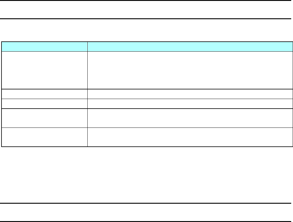
Chapter 3 Disassembly and Maintenance
3-2. Cleaning, 3-3. Lubrication
3-5 CL-S700/CL-S703/CL-S700R
3-2. Cleaning
Cleaning spots are listed below.
Cleaning Position Description
Cabinet Wipe soiled parts of the printer with a clean dry cloth. Remove bits
of media, etc., using tweezers.
Note: When cleaning, be careful not to scratch the equipment or to
bend parts, etc.
Thermal head Clean the thermal head with the head cleaner provided.
Platen Clean the platen with a soft cloth.
Rollers
(for CL-S700R only)
Clean the peeler rollers (on the front cover side and printer side)
with a soft cloth.
Media running surface Wipe off media refuse, etc., on and around the media running
surface.
Clean inside the printer in accordance with the following:
• Cleaning frequency: Every 6 months or 300 hours of operation. (Whichever comes first)
• Materials: Dry cloth (gauze or soft cloth) and thermal head cleaner
3-3. Lubrication/Adhesive Agent
3-3-1. Lubrication
(1) Lubrication frequency
This is a maintenance-free machine and requires no lubrication under normal use. However,
the machine should be lubricated whenever it is disassembled and reassembled, or when
lubricated parts are cleaned.
The parts and places to be lubricated are indicated in the disassembly procedure.
(2) Types of lubricant
• Floil G-311S (by Kanto Chemical Co., Ltd.)
(3) Quantity of lubricant
Small quantity.......... ............. About 1 drop.
Ordinary quantity .... ......... About 3 to 4 drops.
About 0.2 mm thick for grease.
Large quantity.......... ....... Apply sufficiently.
3-3-2. Adhesive Agent
• ThreeBond 1401B (by ThreeBond Co., Ltd.)
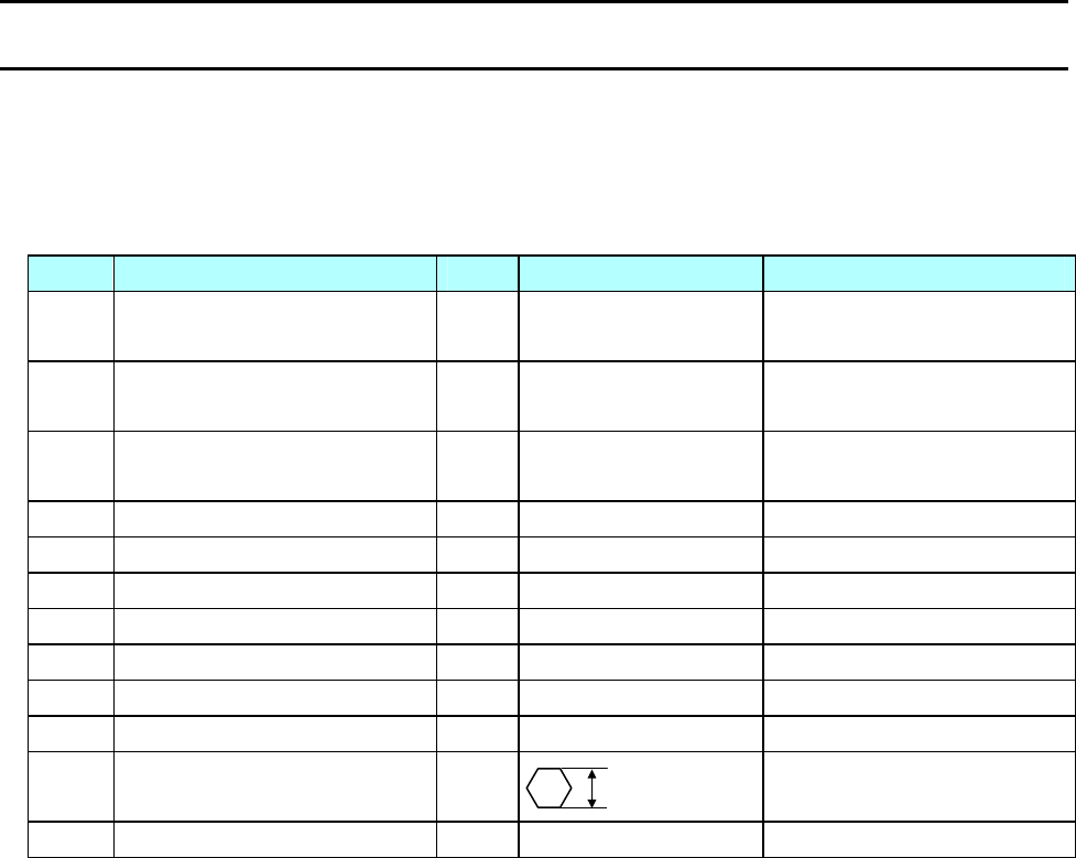
Chapter 3 Disassembly and Maintenance
3-4. Maintenance Tools List
CL-S700/CL-S703/CL-S700R 3-6
3-4. Maintenance Tools List
Maintenance tools shown below are needed when replacing the maintenance parts such as the
“SA, Main PCB” and “Unit, Motor”.
Maintenance Tools List
No. Name Q'ty Description Remarks
1 Phillips Screwdriver
(Length 200 mm)
1 For 3~4 mm screws
2 Phillips Screwdriver
(Length 100 mm)
1 For 2~3 mm screws
3 Flat-blade Screwdriver
(Length 100 mm)
1 4.3 mm width
4 Tweezers 1
5 Round Nose Pliers 1
6 Cutting Nippers 1
7 Soldering Iron (30W) 1
8 Volt-ohm Meter 1
9 Spring Gauge 1 2000gf Belt tension adjustment
10 Spring Gauge 1 500gf Ribbon tension adjustment
11 Hex Wrench 1
Ribbon tension adjustment
12 Weight 1 450g Ribbon tension adjustment
2 mm
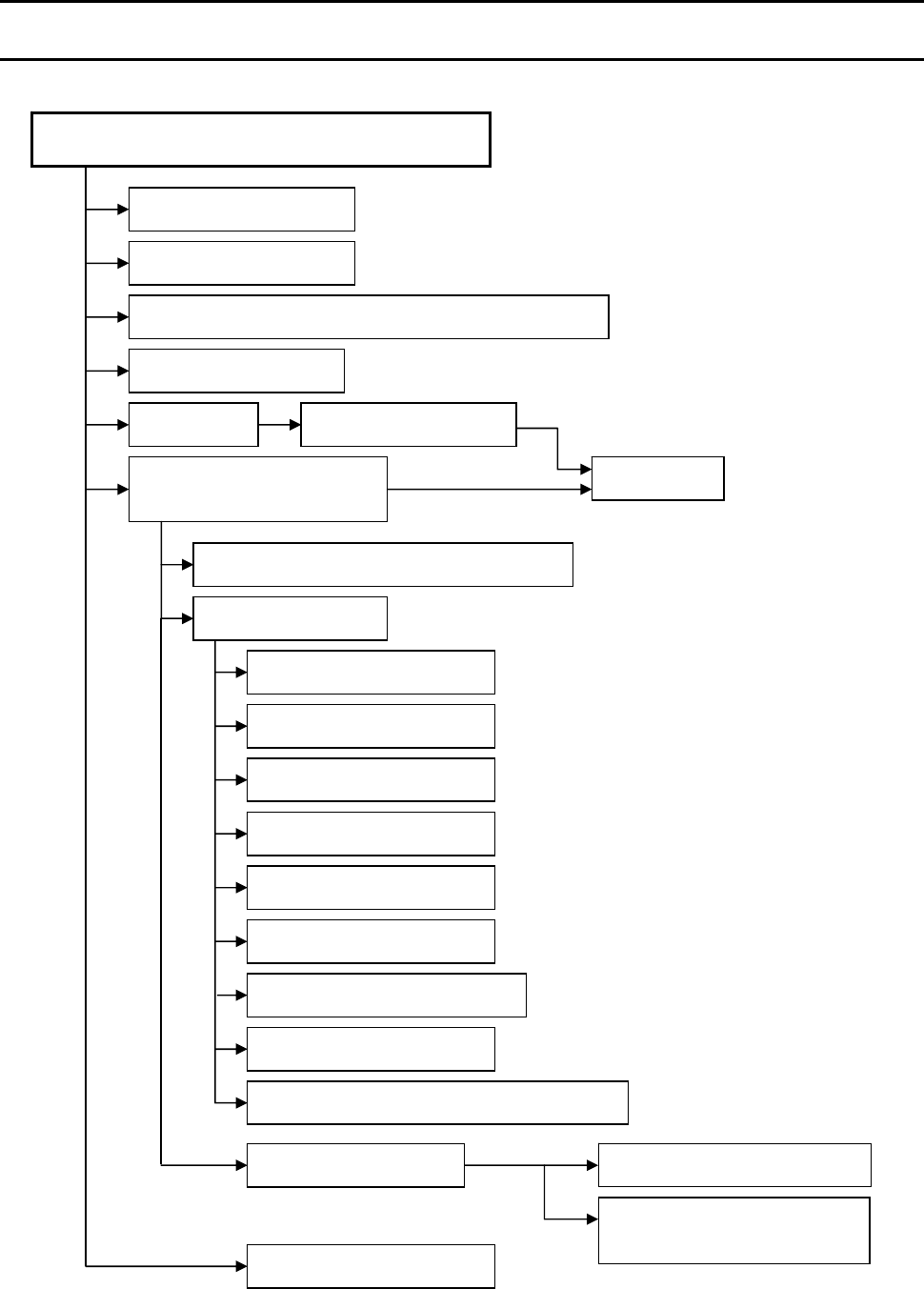
Chapter 3 Disassembly and Maintenance
3-5. Disassembly, Reassembly and Lubrication
3-7 CL-S700/CL-S703/CL-S700R
3-5. Disassembly, Reassembly and Lubrication
[Disassembly Flow]
Unit, Head
CL-S700, CL-S703, CL-S700R (Printer Part)
Unit, Roller Platen
SA, Ope-pane PCB and SA, Cover Open Sens
Connectors on the SA,
Main PCB
Unit, Power Su
pp
l
y
SA, Fan
SA, Base Guide O
p
en
Unit, Mechanism
SA, F
r
ont Tension Arm
SA, Frame Ribbon R
Unit, Frame Rea
r
Unit, Frame U
SA, Sensor U
(
Fixed
)
Unit, Frame Ribbon L
Unit, Moto
r
SA, Connect PCB
(
CL-S700/CL-S703
)
SA, Sensor Bottom
(
Fixed
)
SA, Sensor U
(
Ad
j
ustable
)
SA, Sensor Bottom
(Adjustable)
To
p
Cove
r
SA1, Top Cove
r
SA, Main PCB and Unit, Centro PCB
See 3-5-2.
See 3-5-1.
See 3-5-3.
See 3-5-7.
See 3-5-4.
See 3-5-5 (1). See 3-5-6.
See 3-5-5 (2).
See 3-5-8.
See 3-5-12.
See 3-5-13.
See 3-5-14.
See 3-5-15.
See 3-5-16.
See 3-5-17 “Unit, Frame”.
See 3-5-17 “Unit, Frame”.
See 3-5-17 “Unit, Frame”.
See 3-5-17 “Unit, Frame”.
See 3-5-11.
See 3-5-10.
Unit, Sensor Ad
j
ust

Chapter 3 Disassembly and Maintenance
3-5. Disassembly, Reassembly and Lubrication
CL-S700/CL-S703/CL-S700R 3-8
[How to refer to the exploded diagram in Chapter 5 “Parts List”]
This section explains how to disassemble, reassemble and lubricate.
However, for disassembly procedures, illustrations are not fully provided. For parts that are not
illustrated here, the parts location Nos. in the drawing in Chapter 5 “Parts List” are stated.
Example: Remove 3 screws (BH, M3x5) [1-37] and detach “Unit, PCB” [1-12] backwardly.
In this example, [1-37] and [1-12] are the parts location Nos. Please refer to the parts location
Nos. “1-37” and “1-12” in Drawing No. 1 in Chapter 5 “Parts List”.
When reassembling parts, follow “Note(s) on reassembling” described at the end of
disassembly procedure.
When the parts to be lubricated are replaced, necessity of lubrication is stated in the
reassembling procedure. The places to be lubricated are indicated in the drawings in Chapter 5,
with the mark .
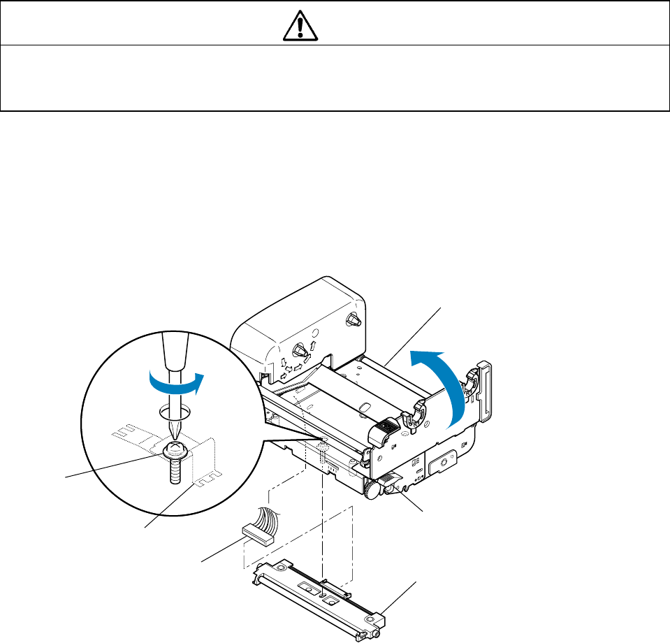
Chapter 3 Disassembly and Maintenance
3-5. Disassembly, Reassembly and Lubrication
3-9 CL-S700/CL-S703/CL-S700R
3-5-1. Unit, Head
- Carefully handle the “Unit, Head” when disassembling and reassembling so as not to
damage the thermal elements of the “Unit, Head”. Especially, avoid contacting the
thermal elements with the metal part, etc.
The “Unit, Head” can be removed easily without detaching any other parts.
1. Open the top cover.
2. Open the head block by pushing the head open lever.
3. While holding the “Unit, Head”, turn the screw until the “Unit, Head” comes off.
4. Remove the “SA, Head Cable” from the “Unit, Head”.
Notes on reassembling:
• When attaching the “Unit, Head”, do not strongly push it against the head block. The Head Earth
Plate may come off if you push the “Unit, Head” strongly.
• Securely fasten the “Unit, Head” with the screw.
• When you replace the “Unit, Head” with a new one, adjust the angle of head spacer shaft, if
ribbon wrinkles are not removed. (This adjustment will be required only when satisfactory results
are not obtained by adjusting the ribbon tension with the adjusting screws of the “Unit, Ribbon
Frame L”.)
Refer to “3-6-3. Ribbon Skew Adjustment”.
Caution
Unit, Head
(Head Open Lever)
SA, Head Cable
Screw
(Head Block)
Head Earth Plate
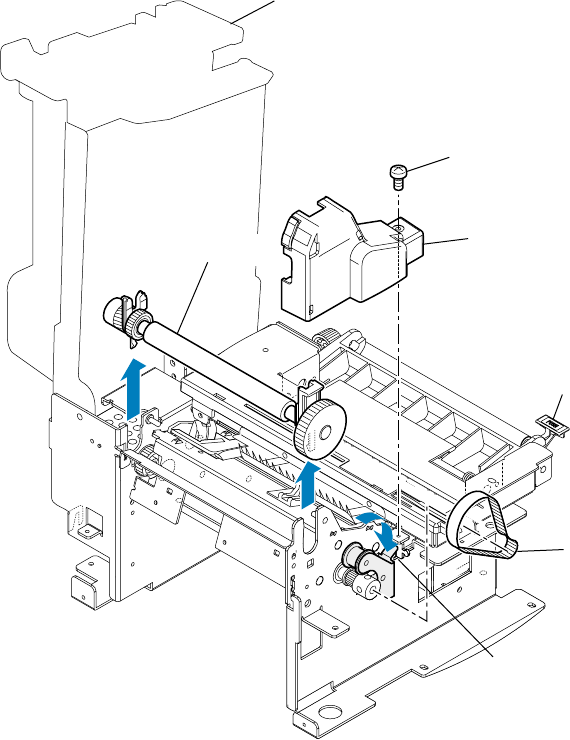
Chapter 3 Disassembly and Maintenance
3-5. Disassembly, Reassembly and Lubrication
CL-S700/CL-S703/CL-S700R 3-10
3-5-2. Unit, Roller Platen and Gear, One-way
The “Unit, Roller Platen” can be removed easily with the following procedure.
The “Unit, Roller Platen” includes the “Gear, One-way” which can be separately replaced.
(1) Removing the “Unit, Roller Platen”
1. Open the top cover.
2. Open the head block by pushing the head open lever.
3. Open the sensor arm block by pushing the sensor arm open lever.
4. Remove 1 screw (BH, M3x5K) and detach the “Cover, Pulley” upwardly after disengaging
its 2 claws.
5. Push the lever of the tension plate unit downward to set the “Belt, Platen Drive” free and
remove the “Belt, Platen Drive” to the right.
6. Lift the “Unit, Roller Platen” and remove it upwardly.
Note on reassembling:
• Be sure that the “Belt, Platen Drive” is securely installed on the gear of the “Unit, Roller
Platen” via the “Unit, Tension Plate”.
(Head Block)
Cover, Pulley
BH, M3x5K
Belt, Platen Drive
Unit, Roller Platen
(Unit, Tension Plate)
(Sensor Arm Open Lever)
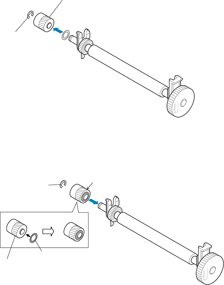
Chapter 3 Disassembly and Maintenance
3-5. Disassembly, Reassembly and Lubrication
3-11 CL-S700/CL-S703/CL-S700R
(2) Removing the “Gear, One-way”
1. Remove the “Unit, Roller Platen” referring to above “(1) Removing the “Unit, Roller
Platen””.(1) Removing the “Unit, Roller Platen”(1) Removing the “Unit, Roller Platen”
2. Disengage 1 E-ring (E-Ring, 4) and remove the “Gear, One-way” from the shaft of the “Unit,
Roller Platen”.
Note on reassembling:
• Insert the plastic washer into the projection of the “Gear, One-way” (on the gear part side).
Then, insert the “Gear, One-way” into the shaft of the “Unit, Roller Platen”, while facing the
gear part of the “Gear, One-way” toward the “Unit, Roller Platen”.
Gear, One-way
E-ring, 4
Gear part
E-ring, 4
Gear, One-way
Plastic washer
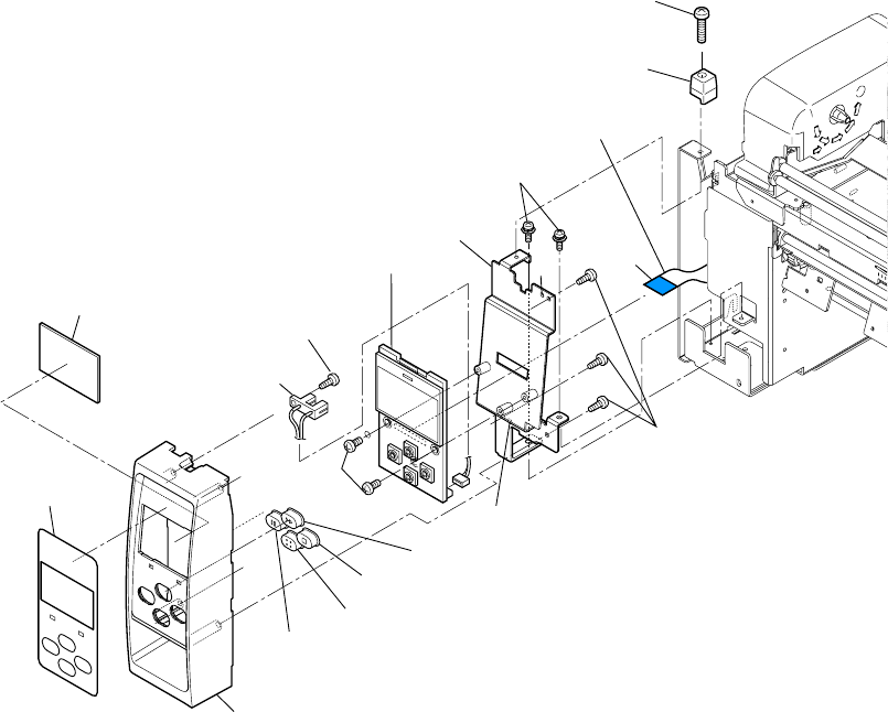
Chapter 3 Disassembly and Maintenance
3-5. Disassembly, Reassembly and Lubrication
CL-S700/CL-S703/CL-S700R 3-12
A
BH, M3x5
PHT (#2), M3x6
PHT (#2), M3x6
B
PH (SW+PW), M3x5
PH, M3x12
SA, Ope-pane PCB
SA, Ope-pane Plate
SA, Cover Open Sens
Guide, Top Cover
Cable, Ope-pane FFC
(Blue Tape)
Switch, Pause
Switch, Feed
Switch, Stop
Switch, Menu
Cover, Ope-Pane
Cover, LCD
Sheet, Ope-Pane
3-5-3. SA, Ope-pane PCB and SA, Cover Open Sens
1. Open the top cover.
2. Remove 1 screw (PH, M3x12) and detach the “Guide, Top Cover”.
3. Remove 2 screws (PH (SW+PW), M3x5) (1 screw for new type) and detach the Ope-pane
block frontward.
4. Disconnect the “Cable Ope-pane FFC” from the “SA, Ope-pane PCB”.
5. Remove 3 screws (PHT (#2), M3x6) and detach the “SA, Ope-pane Plate” (with the “SA,
Ope-pane PCB”) from the Ope-pane Cover block.
6. Remove 2 screws (BH, M3x5) and detach the “SA, Ope-pane PCB” from the “SA, Ope-pane
Plate”.
7. Disconnect the connector of “SA, Cover Open Sens” from the “SA, Ope-pane PCB”.
8. Remove 1 screw (PHT (#2), M3x6) and detach the “SA, Cover Open Sens” from the Ope-pane
Cover block.
9. Detach four switches (PAUSE, FEED, STOP and MENU).
10. Peel off the “Sheet Ope-Pane” from the “Cover Ope-Pane” and remove the “Cover LCD” from
the “Sheet Ope-Pane”.
Notes on reassembling:
• Assemble each switch in place.
• When assembling the “SA, Ope-pane Plate” in the Ope-pane Cover block, fit the holes “A” and
“B” to the protrusions.
• Insert the “Cable Ope-pane FFC” with its blue tape facing up.
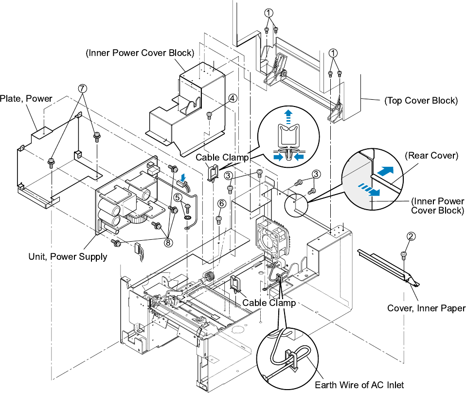
Chapter 3 Disassembly and Maintenance
3-5. Disassembly, Reassembly and Lubrication
3-13 CL-S700/CL-S703/CL-S700R
3-5-4. Unit, Power Supply
1. Open the top cover and remove 4 screws (1BH, M3x5), then detach the Top Cover block.
2. Open the head block by pushing the head open lever.
3. Open the sensor arm block by pushing the sensor arm open lever.
4. Remove 1 screw (2BH, M3x5) and detach the “Cover, Inner Paper”.
5. On the left rear side of the printer, remove 4 screws (3BH, M3x5K) and 1 screw (4BH, M3x5).
Then, while pushing the rear cover toward the rear to make a clearance, remove the Inner
Power Cover block to the right. (See the magnified figure.)
6. Remove 2 cable clamps. (Access to their locks from the bottom of the printer and release the
locks.)
7. Remove 1 screw (5BH (N), M4x4) and 1 toothed lock washer (5EXT, T (N), 4).
8. Remove 1 screw (6BH, M3x5K) and 2 screws (7PH (SW+PW), M3x5), and detach the “Plate,
Power” (with “Unit, Power Supply”) to the right.
9. Disconnect 2 connectors and remove 4 screws (8PH (SW+PW), M3x5) from the “Unit, Power
Supply”. (Before disconnecting the upper right connector, release its lock.)
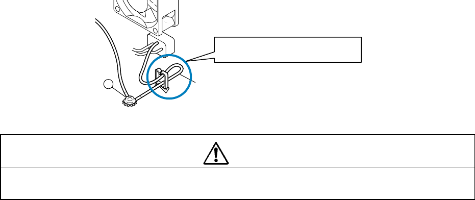
Chapter 3 Disassembly and Maintenance
3-5. Disassembly, Reassembly and Lubrication
CL-S700/CL-S703/CL-S700R 3-14
Notes on reassembling:
• When connecting connectors to the “Unit, Power Supply”, be sure to insert them securely.
• Pass the wires into the cable clamp as they were.
• When fastening the earth wire of the “Unit, Power Supply” to the chassis with the screw (5) and
the toothed lock washer (5), be sure to check the earth wire of the AC outlet runs as follows.
If not arrange it as shown.
- To satisfy the regulated standards, run the earth wire of the AC outlet as shown
above.
Caution
Arrange the wire like this.
Earth Wire of AC Inlet
5
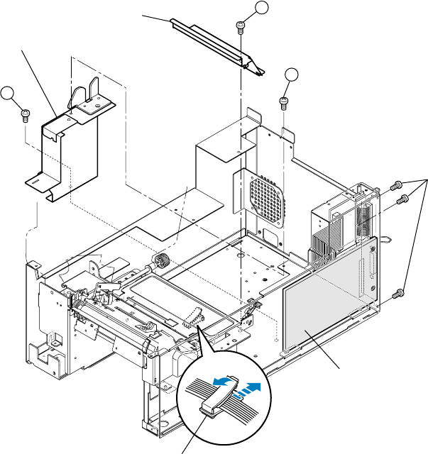
Chapter 3 Disassembly and Maintenance
3-5. Disassembly, Reassembly and Lubrication
3-15 CL-S700/CL-S703/CL-S700R
3-5-5. SA, Main PCB and Unit, Centro PCB
The following 2 steps are explained here.
- Disconnecting all connectors from the “SA, Main PCB”
- Removing “SA, Main PCB” and “Unit, Centro PCB”
(1) Disconnecting all connectors from the “SA, Main PCB”
1. Open the top cover.
2. Open the head block by pushing the head open lever.
3. Open the sensor arm block by pushing the sensor arm open lever.
4. Remove 1 screw (1BH, M3x5) and detach the “Cover, Inner Paper”.
5. Remove 1 screw (2BH, M3x5K) and 1 screw (3BH, M3x5) and detach the Inner PCB
Front Cover block.
Cover, Inner Paper
Inner PCB Front Cover Block
BH, M3x3K
Clamp, Main Cable
Unit, PCB
1
2
3
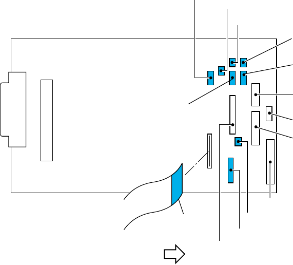
Chapter 3 Disassembly and Maintenance
3-5. Disassembly, Reassembly and Lubrication
CL-S700/CL-S703/CL-S700R 3-16
6. Disconnect all connectors from the “SA, Main PCB”.
J15 and J16: Release the lock before pulling out.
7. Open the “Clamp, Main Cable” and take out each cable.
In the above figure, the cable of which connector color is tinted (blue) runs through the
“Clamp, Main Cable”.
They are J4, J5, J6, J7, J8, J9, J21 and J22.
Notes on reassembling:
• Clamp the following cables with the “Clamp, Main Cable”.
The cables with tinted (blue) connectors in the above figure:
J4, J5, J6, J7, J8, J9, J21 and J22.
• Insert the “Cable, Ope-pane FFC” with its blue tape facing the right.
(2) Removing “SA, Main PCB” and “Unit, Centro PCB”
1. Remove all connectors from the “SA, Main PCB”. (See above.)
2. On the rear right of the printer, remove 3 screws (BH, M3x5K) and detach “Unit, PCB”.
(See the figure on the previous page.)
3. Disconnect the “SA, Centro Cable” [14-1] from the “SA, Main PCB” [14-2] and the “Unit,
Centro PCB” [14-4].
4. Remove 2 lock screws [14-5] and 2 screws (PH (SW+PW), M3x5), and detach the “SA,
Main PCB” [14-2] from the “SA, Holder I/F” [14-3].
5. Remove 2 screws (BH, M3x5) [14-7] and detach the “Unit, Centro PCB” [14-4] from the
“SA, Holder I/F” [14-3].
J16
J12
J6
J21
J7
J22
J11
J5
J4
J15
J3
J14
J9
J8
Front
SA, Main PCB
Ribbon Encoder
(Ribbon Running Sensor/Ribbon End Sensor)
SA, Head Up SW (Head Up Sensor)
Adjustable Sensor (Transparent sensor)
Front Fixed Sensor
(Transparent sensor)
Adjustable Sensor
(Reflective sensor)
Front Fixed Sensor
(Reflective sensor)
SA, Connect PCB (J801) (CL-S700/CL-S703)
SA, Rewinder PCB (J501) (CL-S700R)
SA, Fan
Unit, Head
Unit, Motor
Unit, Motor (Thermistor)
Unit, Power Supply
Ope-Pane FFC Cable (Blue Tape)
SA, Connect PCB (J803) (CL-S700/CL-S703)
SA, Rewinder PCB (J502) (CL-S700R)
Chapter 3 Disassembly and Maintenance
3-5. Disassembly, Reassembly and Lubrication
3-17 CL-S700/CL-S703/CL-S700R
3-5-6. SA, Fan
1. Disconnect J12 (for “SA, Fan”) from the “SA, Main PCB”.
Refer to “3-5-5. SA, Main PCB and Unit, Centro PCB” - “(1) Disconnecting all connectors from
the “SA, Main PCB””.
2. Remove the “Plate, Power” [1-14] (together with “Unit, Power Supply”).
Refer to “3-5-4. Unit, Power Supply.
3. Remove 4 screws (PH (SW+PW), M4x30) [1-40] and detach the “SA, Fan” [1-20].
Notes on reassembling:
• Assemble the “SA, Fan” [1-20] so that its cable runs from the right bottom side as shown in
Drawing 1 “General Assembly” in Chapter 5 “Parts List” (the label of “SA, Fan” will face
backward). In this direction, air flows from inside to outside.
• When assembling the “Plate, Power” [1-14] (together with “Unit, Power Supply”), observe the
“Notes on reassembling” in “3-5-4. Unit, Power Supply.
3-5-7. SA1, Top Cover
1. Open the top cover.
2. Remove 2 screws (BH, M3x5K) [1-39] and detach the 2 “Cover, Hinge” [1-4] from the top cover
by releasing their claws.
3. Remove 4 screws (BH, M3x5) [1-37] and detach the Top Cover block from the printer.
4. Remove 4 screws (BH, M3x5) [1-37] and detach the 2 “Stopper, Hinge” [1-8] and the “SA,
Hinge” [1-9] from the “Unit, Top Cover” [1-3].
5. Remove 2 screws (PHT (#2), M3x6) [10-6] and remove the Front Top Cover block from the
“SA1, Top Cover” [10-1].
6. Pull out the “Cover, Cutter Blind” [10-4] and take off the “Logo, CITIZEN” [10-3] from the “Cover,
Front Top” [10-2].
7. Remove the “Cover, Window” [10-5] and 4 “Spacer Leg, Case U” [10-7] from the “SA1, Top
Cover” [10-1].
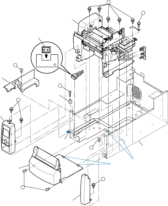
Chapter 3 Disassembly and Maintenance
3-5. Disassembly, Reassembly and Lubrication
CL-S700/CL-S703/CL-S700R 3-18
3-5-8. Unit, Mechanism
1. Open the top cover.
2. Disconnect all connectors except J11 (Power Supply Unit cable) and J12 (Fan SA cable) from
the “SA, Main PCB”.
Refer to “3-5-5. SA, Main PCB and Unit, Centro PCB” - “(1) Disconnecting all connectors from
the “SA, Main PCB””.
3. Remove 1 screw (1BH, M3x5K) and detach the Cable Cover.
4. Remove 1 screw (2PH, M3x12) and detach the “Guide, Top Cover”.
5. Remove 2 screws (3PH (SW+PW), M3x5) (1 screw for new type) and detach the “SA,
Ope-pane” frontward.
6. Disconnect the “Cable, Ope-pane FFC” from the “SA, Ope-pane”.
7. Remove 1 screw (4BH, M3x5K) and 1 screw (5PH (SW+PW), M3x5), and detach the “SA,
Front Right”.
8. Remove 2 screws (6BH, M3x5) and detach the “SA, Front Center” by drawing it out.
9. Disengage the Power Switch from the chassis by lifting it upwardly.
10. Remove 5 screws (7PH (SW+PW), M3x5) and 1 screw (8PH (SW+PW), M3x5), and gently
detach the “Unit, Mechanism” forward after lifting it a little.
2
1
3
5
6
7
8
Unit, Mechanism
Power Switch
Cable Cover
Guide, Top Cover
SA, Ope-Pane
Cable, Ope-Pane
FFC
SA, Front Right
SA, Front Center
4
J3
J12
J15
A
SA, Case L
B
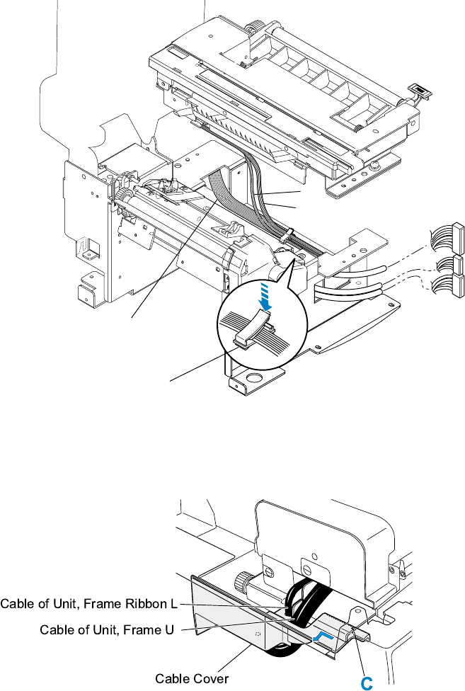
Chapter 3 Disassembly and Maintenance
3-5. Disassembly, Reassembly and Lubrication
3-19 CL-S700/CL-S703/CL-S700R
Notes on reassembling:
• Fit the holes in the chassis of the “Unit, Mechanism” to the protrusions of the “SA, Case L” to
securely seat the “Unit, Mechanism” onto the “SA, Case L”.
• Securely fasten the earth wire with the screw (8PH (SW+PW), M3x5).
• Install the Power Switch as shown in the figure (set its “l (ON)” side to the right).
• When assembling the “SA, Front Center”, assemble it so that its claws “A” shown in the figure
are securely inserted into the slits “B” on the “SA, Case L”.
• See the following wiring route for “Unit, Mechanism” and pass the cables (J4 to J9, J21 and J22)
through the “Clamp, Main Cable”.
[Wiring route for “Unit, Mechanism”]
• When assembling the Cable Cover, first insert its right side while aligning the slit “C” and then fit
the Cable Cover by shifting in the direction of the arrow
Also, be sure that the cables are correctly routed in the Cable Cover as shown below.
Clamp, Main Cable
J16
J15
J3
Other Connectors
(J4, J5, J6, J8, J9, J21)
J7
J22
Chapter 3 Disassembly and Maintenance
3-5. Disassembly, Reassembly and Lubrication
CL-S700/CL-S703/CL-S700R 3-20
3-5-9. Each Unit on the “Unit, Mechanism”
The following shows the procedures how to disassemble each unit from the “Unit, Mechanism”.
Refer to the Drawing No. 2 “Unit, Mechanism” in Chapter 5 “Parts List”.
1. Remove the “Unit, Mechanism”.
Refer to “3-5-8. Unit, Mechanism.
2. Remove the “SA, Base Guide Open” [2-10].
Refer to “3-5-10. SA, Base Guide Open.
3. Remove the “Unit, Sensor Adjust” [2-12].
Refer to “3-5-11. Unit, Sensor Adjust.
4. Remove the “Unit, Frame Ribbon L” [2-19].
Refer to “3-5-12. Unit, Frame Ribbon L.
5. Remove the “SA, Front Tension Arm” [2-4].
Refer to “3-5-13. Disassembling the “SA, Front Tension Arm””.
6. Remove the “SA, Frame Ribbon R” [2-9].
1) Remove 1 screw (PH (SW+PW), M3x5) [2-22] and 2 screws (FT, M3x6) [2-23], and detach
the “SA, Frame Ribbon R” [2-9] upwardly.
For disassembling the parts of the “SA, Frame Ribbon R” [2-9], refer to “3-5-14.
Disassembling the “SA, Frame Ribbon R””.
7. Remove the “Unit, Frame Rear” [2-5].
1) Remove 2 screws (PH (SW+PW), M3x5) [2-22] and detach the “Unit, Frame Rear” [2-5].
For disassembling the parts of the “Unit, Frame Rear” [2-5], refer to “3-5-15. Disassembling
the “Unit, Frame Rear””.
8. Remove the “Unit, Frame U” [2-6].
1) Remove the “Unit, Head” [2-8] referring to “3-5-1. Unit, Head.
2) With the head block opened, disengage the “Spring, Head Up” [2-7] from the “Unit, Frame
U” [2-6] and the “Unit, Frame” [2-18].
3) Remove 1 screw (PH, M4x6) [2-24] and detach Damper [2-14] and “SA, Head Up SW”
[2-16].
4) Remove the Damper Pin [2-15] while swinging the “Unit, Frame U” [2-6] as it presses down
the Damper Pin [2-15], and then detach the “Unit, Frame U” [2-6] from the “Unit, Frame”
[2-18].
For disassembling the parts of the “Unit, Frame U” [2-6], refer to “3-5-16. Disassembling
the “Unit, Frame U””.
Note on reassembling:
• Apply grease (Floil G-311S) to the following points (refer to the places marked with in
Drawing No. 2 “Unit, Mechanism” for the Printer Part in Chapter 5 “Parts List”):
• Damper Pin [2-15]: Both ends
• “Unit, Frame U” [2-6]: Where the “Spring, Head Up” [2-7] is to be hooked
• “Unit, Frame” [2-18]: Where the “Unit, Frame U” [2-6] is to be hooked
Chapter 3 Disassembly and Maintenance
3-5. Disassembly, Reassembly and Lubrication
3-21 CL-S700/CL-S703/CL-S700R
9. Remove the “Unit, Frame” [2-18].
1) Detach the “Sheet 2, Power Protect” [2-13] and “Clamp, Main Cable” [2-17] from the “Unit,
Frame” [2-18].
For disassembling parts of the “Unit, Frame” [2-18], refer to “3-5-17. Disassembling the
“Unit, Frame””.
Note on reassembling:
• Apply grease (Floil G-311S) to the following points (refer to the places marked with in
Drawing No. 2 “Unit, Mechanism” for the Printer Part in Chapter 5 “Parts List”):
• “Unit, Frame” [2-18]: Where the “Spring, Head Up” [2-7] is to be hooked
• “Unit, Frame” [2-18]: Where the “Unit, Frame U” [2-6] is to be hooked
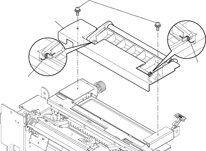
Chapter 3 Disassembly and Maintenance
3-5. Disassembly, Reassembly and Lubrication
CL-S700/CL-S703/CL-S700R 3-22
3-5-10. SA, Base Guide Open
(1) Removing the “SA, Base Guide Open”
Note: The “SA, Base Guide Open” can be removed without removing the “Unit, Mechanism”.
1. Open the top cover.
2. Open the head block by pushing the head open lever.
3. Remove 2 screws (PH (SW+PW), M3x5) and detach the “SA, Base Guide Open”. Refer to
the figure shown below.
(2) Disassembling the “SA, Base Guide Open”
1. Remove 2 screws (PH (SW+PW), M3x5) [7-8] and pull out 2 “SA, Damper Shaft” [7-1] on
both sides.
2. Remove the Damper Frame block (Plastic) from the “Frame, Damper” (Metal) [7-2].
3. Remove the “Spring, Damper L” [7-6] and “Spring, Damper R” [7-7], disengage 1 E-ring
(E-Ring, 4) [7-3], and pull out the “Shaft, Damper” [7-4] from the “Frame, Damper” (Plastic)
[7-5].
Note on reassembling:
• Assemble the Damper L Spring [7-6] and “Spring, Damper R” [7-7] referring to above figure.
Spring, Damper L
Spring, Damper R
PH (SW+PW), M3x5
SA, Base Guide Open
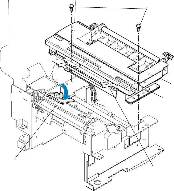
Chapter 3 Disassembly and Maintenance
3-5. Disassembly, Reassembly and Lubrication
3-23 CL-S700/CL-S703/CL-S700R
3-5-11. Unit, Sensor Adjust
(1) Removing the “Unit, Sensor Adjust”
Note: The “Unit, Sensor Adjust” can be removed without removing the “Unit, Mechanism”.
1. Open the top cover.
2. Disconnect the connectors J7 and J22 from the “SA, Main PCB”.
Refer to “3-5-5. SA, Main PCB and Unit, Centro PCB” - “(1) Disconnecting all connectors
from the “SA, Main PCB””.
3. Remove 2 screws (PH (SW+PW), M3x5) and detach both “Unit, Sensor Adjust” and “SA,
Base Guide Open”.
4. Remove the “SA, Base Guide Open” from the “Unit, Sensor Adjust”.
Refer to “3-5-10. SA, Base Guide Open.
5. Peel off the Ground Brush from the “Unit, Sensor Adjust”.
Notes on reassembling:
• Be sure to lower the “SA, Sensor U” (Fixed type) before assembling the “Unit, Sensor
Adjust”.
• Run the cables (J7 and J22) as shown and be sure that they are not pinched by the “Unit,
Sensor Adjust”.
Unit, Sensor Adjust
SA, Sensor U (Fixed type)
PH (SW+PW), M3x5
SA, Base Guide Open
J7
J22
Ground Brush
Chapter 3 Disassembly and Maintenance
3-5. Disassembly, Reassembly and Lubrication
CL-S700/CL-S703/CL-S700R 3-24
(2) Disassembling the “Unit, Sensor Adjust”
1. Remove the “SA, Sensor U” (Adjustable type) [8-9] and “Shaft, Screw Sensor U” [8-5].
1) Shift the “Cover, Sensor Adjust” [8-2] to the right and remove it upwardly.
Peel off the “Open Guide Seal” [8-1] from the “Cover, Sensor Adjust” [8-2].
2) On the right side, disengage 1 E-ring (E-Ring, 2) [8-28], shift the “Shaft, Screw Sensor
U” [8-5] to the left about 2 mm (0.08”), and remove the block (consisting of “Shaft,
Screw Sensor U” [8-5] and “SA, Sensor U” (Adjustable type) [8-9], etc.) to the right.
3) Peel off Position Label [8-6], remove 2 screws (No. 0, FHT (BT#1), M2x4) [8-27],
Stopper Plate [8-7] and Move Pin [8-8] from the “SA, Sensor U” (Adjustable type) [8-9].
4) Cut the Wire Tie [8-10].
5) Pull out the “SA, Sensor U” (Adjustable type) [8-9] from the “Shaft, Screw Sensor U”
[8-5].
6) Disengage 1 E-ring (E-Ring, 3) [8-26], pull out the “Pin, Teeth Spring 1.2x8” [8-3], and
remove the Screw Gear [8-4] to the left from the “Shaft, Screw Sensor U” [8-5].
Notes on reassembling:
• Do not reuse the “Pin, Teeth Spring 1.2x8” [8-3].
• Apply grease (Floil G-311S) to the “Shaft, Screw Sensor U” [8-5] at 3 places (marked
with in Drawing No. 8 “Unit, Sensor Adjust” for the Printer Part in Chapter 5 “Parts
List”).
2. Remove the “SA, Sensor Bottom” (Adjustable type) [8-24] and “Shaft, Screw Sensor L”
[8-23].
1) Remove 1 screw (PH (SW+PW), M3x5) [8-29] and detach the Ratchet Spring [8-31].
2) On the right side, disengage 1 E-ring (E-Ring, 3) [8-26], shift the “Shaft, Screw Sensor
L” [8-23] to the left about 2 mm, and remove the block (consisting of “Shaft, Screw
Sensor L” [8-23] and “SA, Sensor Bottom” (Adjustable type) [8-24], etc.) to the right.
3) Cut the Wire Tie [8-10].
4) Pull out the “SA, Sensor Bottom” (Adjustable type) [8-24] from the “Shaft, Screw
Sensor L” [8-23].
5) Disengage 1 E-ring (E-Ring, 3) [8-26], pull out the “Pin, Teeth Spring 1.2x8” [8-3], and
remove the Screw Gear [8-4] to the left from the “Shaft, Screw Sensor L” [8-23].
Also, remove the Ratchet Gear [8-19] from the “Shaft, Screw Sensor L” [8-23], after
pulling out the “Pin, Teeth Spring 1.2x8” [8-3].
Notes on reassembling:
• Do not reuse the “Pin, Teeth Spring 1.2x8” [8-3].
• Apply grease (Floil G-311S) to the “Shaft, Screw Sensor L” [8-23] at 3 places (marked
with in Drawing No. 8 “Unit, Sensor Adjust” for the Printer Part in Chapter 5 “Parts
List”).
3. Remove the Open Guide Lever [8-12].
1) Disengage 1 E-ring (E-Ring, 2) [8-28] and remove the Open Guide Lever [8-12] and
Open Guide Lever Spring [8-13].
4. Remove the Paper Guide Plate [8-14].
1) Remove 2 screws (PH, M3x3) [8-30] and detach the Paper Guide Plate [8-14].
Chapter 3 Disassembly and Maintenance
3-5. Disassembly, Reassembly and Lubrication
3-25 CL-S700/CL-S703/CL-S700R
5. Remove the “SA, Open Guide U” [8-11].
1) Pull out “Knob, Sensor Adjust” [8-20], disengage 1 E-ring (E-Ring, 3) [8-26], and
remove the “Bushing 3, Adjust Sensor” [8-18] and “Spring, Guide Sensor Up” [8-17]
from the “Shaft, Sensor Adjust” [8-16].
2) Disengage 1 E-ring (E-Ring, 2) [8-28], pull out “Pin, Teeth Spring 1.2x8” [8-3], remove
the Screw Gear [8-4] and “Shaft, Sensor Adjust” [8-16], and detach the “SA, Open
Guide U” [8-11] from the “SA, Open Guide L” [8-22].
Note on reassembling:
• Apply grease (Floil G-311S) to the following points (refer to the places marked with in
Drawing No. 8 “Unit, Sensor Adjust” for the Printer Part in Chapter 5 “Parts List”):
• “Bushing 3, Adjust Sensor” [8-18]: Rear surface (where contacting with E-ring)
• “SA, Open Guide U” [8-11]: 2 holes for the “Shaft, Sensor Adjust” [8-16]
• “SA, Open Guide L” [8-22]: 2 holes for the “Shaft, Sensor Adjust” [8-16]
6. Remove the “SA, Open Guide L” [8-22].
1) Remove 2 screws (PH (SW+PW), M3x5) [8-29] and detach the “Holder, Sensor L”
[8-25].
2) Peel off the “Sheet, Sensor Adjust” [8-15] and “Sheet, Sensor Adjust L” [8-32], and
remove the “Cover, RFID” [8-21] from the “SA, Open Guide L” [8-22].
Note on reassembling:
• Apply grease (Floil G-311S) to the following points (refer to the places marked with in
Drawing No. 8 “Unit, Sensor Adjust” for the Printer Part in Chapter 5 “Parts List”):
• “SA, Open Guide L” [8-22]: 2 holes for the “Shaft, Sensor Adjust” [8-16]
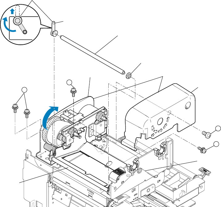
Chapter 3 Disassembly and Maintenance
3-5. Disassembly, Reassembly and Lubrication
CL-S700/CL-S703/CL-S700R 3-26
3-5-12. Unit, Frame Ribbon L
1. Remove the “Unit, Mechanism”.
Refer to “3-5-8. Unit, Mechanism.
2. Remove 1 screw (1PH, M3x6) and detach the “Cover, Ribbon” from the Frame Ribbon L
block.
3. Open the head block by pushing the head open lever and remove 1 screws (2PH (SW+PW),
M3x5).
4. Close the head block and remove 3 screws (3PH (SW+PW), M3x5).
5. On the left side, release the lock of the Bushing (24400670) by turning its end after pushing the
protrusion “A” with tweezers pointing tip, and then detach the Bushing (24400670), “ Shaft,
Ribbon Guide FF”, and the Bushing (24400680).
6. Lift the front side of the Frame Ribbon L block and turn it in the direction shown by the arrow,
and then detach it upwardly.
7. Remove the “Spring, Shaft Guide FF” and “SA, Front Tension Arm” from the “Unit, Mechanism”.
For disassembling parts of the “SA, Front Tension Arm”, refer to “3-5-13. Disassembling the
“SA, Front Tension Arm””.
1
2
3
3
A
Cover, Ribbon
(Frame Ribbon L Block)
Bushing (24400670)
Shaft, Ribbon Guide FF
Bushing (24400680)
SA, Front Tension Arm
Unit, Frame Ribbon L
Spring, Shaft Guide FF
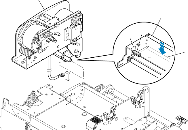
Chapter 3 Disassembly and Maintenance
3-5. Disassembly, Reassembly and Lubrication
3-27 CL-S700/CL-S703/CL-S700R
Notes on reassembling:
When reassembling the “Unit, Frame Ribbon L”, follow the next steps.
1. While pushing down the Ribbon Guide Roller C, insert the shaft “B” of the Frame Ribbon L
block into the hole “C” of the “Unit, Frame Rear”.
(Frame Ribbon L Block)
B
C
Ribbon Guide Roller C
B
Unit, Frame Rear
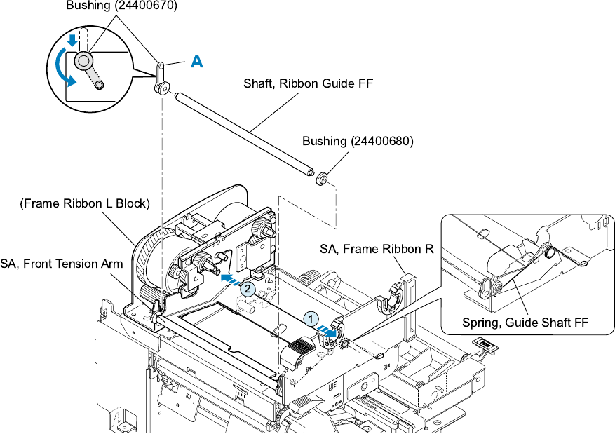
Chapter 3 Disassembly and Maintenance
3-5. Disassembly, Reassembly and Lubrication
CL-S700/CL-S703/CL-S700R 3-28
2. While tilting the Frame Ribbon L block to the left (outer ward) a little, engage the “SA, Front
Tension Arm” with the “SA, Frame Ribbon R” (arrow 1).
At the same time, hook the “Spring, Guide Shaft FF” on the “SA, Front Tension Arm”. Be sure
that both ends of the spring are correctly hooked as shown in the enlarged illustration.
3. Next, engage the left side of the “SA, Front Tension Arm” with the Frame Ribbon L block (arrow
2).
4. Assemble the Bushing (24400680), “Shaft, Ribbon Guide FF” and Bushing (24400670). For
Bushing (24400670), lock its end by turning it so that the protrusion “A” is seated securely.
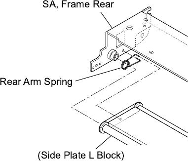
Chapter 3 Disassembly and Maintenance
3-5. Disassembly, Reassembly and Lubrication
3-29 CL-S700/CL-S703/CL-S700R
3-5-13. Disassembling the “SA, Front Tension Arm”
To remove the “SA, Front Tension Arm”, refer to "3-5-12. Unit, Frame Ribbon L.
1. Release the lock of the right side Bushing (24400670) [4-4].
2. Remove the Bushing (24400670) [4-4], “Spring, Shaft Guide FM” [4-5], “Washer, Shaft Guide
FM” [4-6], “Shaft, Ribbon Guide FM” [4-3] and Bushing (24400680) [4-2] from the “SA, Front
Tension” [4-1].
3-5-14. Disassembling the “SA, Frame Ribbon R”
To remove the “SA, Frame Ribbon R”, refer to Step 6 in "3-5-9. Each Unit on the “Unit, Mechanism"
1. Pull out 2 “Holder, Ribbon Shaft” [6-1] upwardly after releasing their locks.
2. Remove the “Knob, Ribbon Unit” [6-2] and “Plate, Ribbon Frame” [6-4] from the “Frame,
Ribbon R” [6-3], after releasing their claws.
3-5-15. Disassembling the “Unit, Frame Rear”
To remove the “Unit, Frame Rear”, refer to Step 7 in "3-5-9. Each Unit on the “Unit, Mechanism".
1. Release the lock of the left side Bushing (24400670) [5-1].
2. Remove the Bushing (24400670) [5-1], Ribbon Guide Roller E [5-2] and Bushing (24400680)
[5-3] from the “SA, Frame Rear” [5-4].
3. Remove 1 screw (PH (SW+PW), M3x5) [5-11] and detach “SA, Plate Stopper Rear” [5-6].
Then, detach the Ribbon Guide block and the Rear Arm Spring [5-5].
4. Remove 4 screws (FT, M3x6) [5-12] and detach all other parts (Side Plate L [5-7], Side Plate R
[5-10], 4 Bushings (24400680) [5-3], 2 Ribbon Guide Rollers C [5-8] and Beam [5-9]).
Note on reassembling:
• Insert the ends of Rear Arm Spring [5-5] into the hole of the “SA, Frame Rear” and the Side Plate
L block as shown below. After assembling it, be sure to check that the spring is correctly hooked
by swinging the Side Plate L block.
Chapter 3 Disassembly and Maintenance
3-5. Disassembly, Reassembly and Lubrication
CL-S700/CL-S703/CL-S700R 3-30
3-5-16. Disassembling the “Unit, Frame U”
To remove the “Unit, Frame U”, refer to Step 8 in "3-5-9. Each Unit on the “Unit, Mechanism".
1. Remove the “SA, Gear Plate” [3-4].
1) Unhook the Gear Plate Spring [3-3] from the “SA, Gear Plate” [3-4].
2) Disengage 3 E-rings (E-Ring, 3) [3-23] and, from the “SA, Gear Plate” [3-4], remove 2 Idle
Gear A Sub Assemblies [3-1], 1 Idle Gear B Sub Assembly [3-2], 3 Polysliders [3-29] and 2
Polysliders 1 [3-22].
Note on reassembling:
• Apply grease (Floil G-311S) to the following points (refer to the places marked with in
Drawing No. 3 “Unit, Frame U” for the Printer Part in Chapter 5 “Parts List”):
• Idle Gear A Sub Assembly [3-1]: Gear surface
• Idle Gear B Sub Assembly [3-2]: Gear surface
2. Bow the Offset Spring [3-13] (which ends are inserted into the frame) and remove it from the
frame.
Note on reassembling:
• Correctly set the Offset Spring [3-13] since the shape of its ends differs.
3. Slide the Head Plate [3-12] backward to remove it. Then the “Spring, Head R” [3-15] and
“Spring, Head L” [3-8] will come off.
4. Remove the following parts from the Head Plate [3-12].
1) Cut the Wire Tie [3-7], remove 1 screw (BH (N), M4x4) [3-26] and 1 washer (EXT, T (N), 4)
[3-27], and detach the “SA, Head Cable” [3-6] and the “SA, Head Earth Cable” [3-32].
2) Remove the Head Earth Plate [3-11] and 1 screw (PH (TP) M3x8) [3-28] and peel off the
“Sheet, Cover Cable” [3-10] from the Head Plate [3-12].
5. Remove the Slider [3-14].
1) Turn the Adjust Screw [3-17] counterclockwise until the nut (Nut, M3) [3-25] comes off.
2) Then, remove the Slider [3-14], Adjust Screw [3-17] and Curved Washer [3-16].
6. Remove the “Lever, Head Up” [3-19].
1) Disengage 1 E-ring (E-Ring, 2) [3-24] and remove 1 Polyslider Washer [3-20], “Lever,
Head Up” [3-19] and Open Lever Spring [3-18].
7. Remove the “SA, Frame U” [3-5].
1) Remove the Nylon Screw [3-21], Head Balance Seal [3-9] and labels ([3-30] and [3-31]).
Note on reassembling:
• Apply grease (Floil G-311S) to the “SA, Frame U” [3-5] (refer to the places marked with in
Drawing No. 3 “Unit, Frame U” for the Printer Part in Chapter 5 “Parts List”).
Chapter 3 Disassembly and Maintenance
3-5. Disassembly, Reassembly and Lubrication
3-31 CL-S700/CL-S703/CL-S700R
3-5-17. Disassembling the “Unit, Frame”
To remove the “Unit, Frame”, refer to Step 9 in "3-5-9. Each Unit on the “Unit, Mechanism"
1. Remove the “SA, Sensor U” (Fixed type) [9-7].
1) Remove 1 screw (PH (SW+PW), M3x6) [9-34] and remove the “SA, Sensor U” (Fixed type)
[9-7].
2. Remove the “SA, Sensor Bottom” (Fixed type) [9-18].
1) Remove 1 screw (No. 0, FHT (BT#1), M2x8) [9-36] and detach the “SA, Sensor Bottom”
(Fixed type) [9-18].
3. Remove the Paper Guide [9-8].
1) While pushing the Paper Guide Spring [9-17], remove it from the hook of the Paper Guide
[9-8]. Then, remove the Friction Cork [9-16] and the Paper Guide [9-8].
4. Remove the “Unit, Motor” [9-38].
1) On the left lower of the “Unit, Mechanism”, remove 3 screws (PH (SW+PW), M3x5) [9-32]
and detach the Motor block and “Belt, Motor Drive” [9-12].
2) Disconnect the “SA, PF MTR Cable” [9-30] from the Motor block, remove 2 screws (PH
(SW+PW), M3x6) [9-33], and detach the ”Bracket, Motor” [9-6] from the “Unit, Motor”
[9-38].
Note on reassembling:
• Adjust the belt tension of the “Belt, Motor Drive” [9-12].
Refer to “3-6-2. Belt Tension Adjustment”.
5. Remove the “Unit, Roller Platen” [9-1].
1) Remove 1 screw (BH, M3x5K) [9-34] and detach the “Cover, Pulley” [9-9].
2) Push the lever of the “Plate, Tension” [9-28] downward and remove the “Belt, Platen Drive”
[9-2], then detach the “Unit, Roller Platen” [9-1] by lifting it upwardly.
Note: For easier disassembly procedure, refer to “3-5-2. Unit, Roller Platen.
6. Remove the “SA 1, Drive Shaft” [9-13].
1) Remove 2 screws (HSS (KCP), M3x5) [9-25] and detach the “Pulley, Drive Shaft” [9-24]
and “Bushing, Motor Drive” [9-23].
2) Pull out the “SA 1, Drive Shaft” [9-13] to the left and remove the 2 “Bearing, Drive Shaft”
[9-14].
7. Remove the Idle Gear Sub Assembly [9-15].
1) Disengage 1 E-ring (E-Ring, 3) [9-36] and remove the Idle Gear Sub Assembly [9-15].
8. Remove the “Plate, Peel” [9-11].
1) Remove 1 screw (PH (SW+PW), M3x6) [9-33] and detach the “Plate, Peel” [9-11].
Chapter 3 Disassembly and Maintenance
3-5. Disassembly, Reassembly and Lubrication
CL-S700/CL-S703/CL-S700R 3-32
9. Remove the Tension Pulley [9-26].
1) Disengage the Tension Spring [9-29] from the Tension Plate block.
2) Disengage 1 E-ring (E-Ring, 3) [9-36] and pull out the Tension Plate block to the right.
3) Disengage 1 E-ring (E-Ring, 2) [9-37], pull out the Tensioner Pin [9-27], and remove the
Tension Pulley [9-26] from the “Plate, Tension” [9-28].
Notes on reassembling:
• Correctly hook the Tension Spring [9-29]. (Refer to Drawing No. 9 “Unit, Frame” in Chapter 5
“Parts List”).
• Apply grease (Floil G-311S) to the Tensioner Pin [9-27] (refer to the places marked with in
Drawing No. 9 “Unit, Frame” for the Printer Part in Chapter 5 “Parts List”).
10. Remove the “SA, Connect PCB” [9-20] (CL-S700/CL-S703).
1) Disconnect the “SA, Option Cable 1” [9-21] (J15) and “SA, Option Cable 2” [9-22] (J16)
from the “SA, Connect PCB” [9-20].
2) Remove 2 screws (PH (SW+PW), M3x6) [9-33] and detach the “SA, Connect PCB” [9-20].
11. Remove the “SA, Frame Center” [9-19].
1) Remove 4 screws (PH (SW+PW), M3x6) [9-33] and detach the “SA, Frame Center” [9-19]
from the “SA, Frame” [9-10].
Chapter 3 Disassembly and Maintenance
3-5. Disassembly, Reassembly and Lubrication
3-33 CL-S700/CL-S703/CL-S700R
3-5-18. Disassembling the Rewinder Part (CL-S700R Only)
Disassembly procedures for the Rewinder part of CL-S700R are explained here.
[Parts to be lubricated]
When the following parts are replaced or reassembled, apply grease (Floil G-311S).
The places to be lubricated are indicated with the mark in the drawings for the Rewinder Part
(the latter half) of Chapter 5 “Parts List”.
Drawing No. 2 “Unit, Rewinder”:
• ”Shaft, Measure Sensor” [2-1]: Both ends of the shaft (2 places)
• ”Shaft, Damper” [2-6]: Both ends of the shaft (2 places)
• “SA, Rewinder Motor” [2-8]: Contacting surface with the “Guide, Motor Plate” [2-10] (1 place)
• “Guide, Motor Plate” [2-10]: Back surface (1 place)
• “Shaft, Handle Plate” [2-24]: Both ends of the shaft (2 places)
• “Plate, Handle” [2-28]: Both holes for the “Shaft, Handle Plate” [2-24] (2 places)
• “SA, Handle Link” [2-29]: Both studs (2 places)
• “Frame, Door L” [2-33]: “Shaft, Door” [2-40] (1 place)
• “Frame, Door R” [2-43]: “Shaft, Door” [2-40] (1 place)
• “Holder, Door Shaft R” [2-44]: Hole for “Shaft, Door” [2-40] (1 place)
Drawing No. 3 “SA1, Peeler”:
• “Roller, Idle Rewinder” [3-1]: Both ends of the shaft (2 places)
• “Bush, Idle” [3-2]: Right side (2 places)
• “Roller, Friction” [3-6]: Both ends of the shaft (2 places)
• “Plate, Sensor Holder” [3-8]: Rear surface at both ends where circled with a dotted line (2
places)
Drawing No. 4 “SA2, Peeler”:
• “Roll, Peel” [4-1]: Both ends of the shaft (2 places)
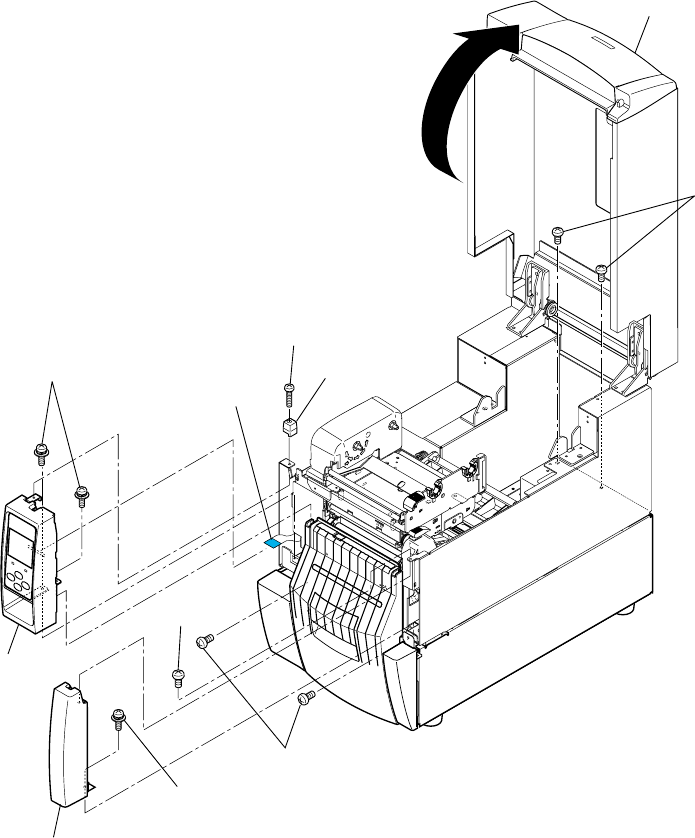
Chapter 3 Disassembly and Maintenance
3-5. Disassembly, Reassembly and Lubrication
CL-S700/CL-S703/CL-S700R 3-34
(1) Separating the Rewinder part
1. Open the top cover.
2. Remove 1 screw (PH, M3x12) and detach the Top Cover Guide.
3. Remove 2 screws (PH (SW+PW), M3x5) and detach the “SA, Ope-pane” frontward.
4. Disconnect the “Cable, Ope-pane FFC” from the “SA, Ope-pane”.
Note on reassembling:
• Insert the “Cable, Ope-pane FFC” with its blue tape facing up.
5. Remove 1 screw (BH, M3x5K) and 1 screw (PH (SW+PW), M3x5), and detach the “SA,
Front Right”.
6. Remove 2 screw (PHT (#2), M3x6) from the front and 2 screws (BH, M3x5) from the rear
side.
Guide, Top Cover
PH, M3x12
Cable, Ope-pane FFC
PH (SW+PW), M3x5
BH, M3x5K
SA, Front Right
PH (SW+PW), M3x5
SA, Ope-pane
PHT (#2), M3x6
(Top Cover)
BH, M3x5
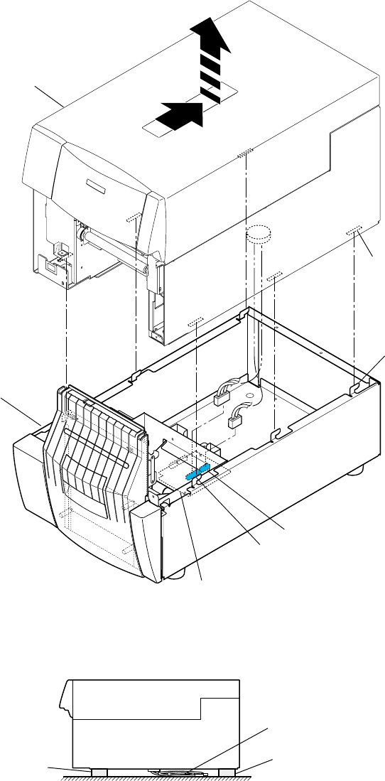
Chapter 3 Disassembly and Maintenance
3-5. Disassembly, Reassembly and Lubrication
3-35 CL-S700/CL-S703/CL-S700R
7. Fully slide the Printer part to the rear.
Then, each claw of the Rewinder part comes off the slit on the Printer part.
8. Lift the Printer part and disconnect 2 cables (J15 and J16) from the connectors (J501 and
J502) of the “SA, Rewinder PCB”.
Tips: To disconnect the cables easier, you can carefully put the Printer part on the
Rewinder part widthwise.
9. Remove the Printer part and place it so as not to damage the cables at the bottom.
The following is an example where spacers (not supplied) are used.
Cables
(Printer Part)
Spacer
Spacer
J16
J15
J502
J501
SA, Rewinder PCB
(Rewinder Part)
(Printer Part)
Claws (6 pcs.)
Slits(6 pcs.)
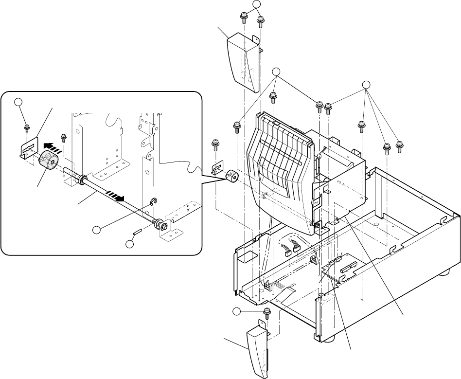
Chapter 3 Disassembly and Maintenance
3-5. Disassembly, Reassembly and Lubrication
CL-S700/CL-S703/CL-S700R 3-36
(2) Removing the Rewinder Mechanism block
1. Remove 2 screws (1PH (SW+PW), M3x5) and detach the “Case, Rewinder Front L”
upwardly.
2. Remove 1 screw (2PH (SW+PW), M3x5) and detach the “Case, Rewinder Front R”
upwardly.
3. Remove 1 screw (3PH (SW+PW), M3x5) and detach the “Plate, Torque Limiter”.
4. Disengage 1 E-ring (4E-Ring, 4), pull out “Pin, Parallel(A), M2x12” (5), and fully move the
Door Shaft block to the right. Then, pull out the Torque Limiter to the left.
Note on reassembling:
• The Torque Limiter can turn in one way only.
5. Disconnect 2 cables from the connectors J503 and J504 of the “SA, Rewinder PCB”.
Note on reassembling:
• Run the cables as shown in the figure.
6. Remove 7 screws (6PH (SW+PW), M3x5) and detach the Rewind Mechanism block
upwardly.
3
4
Plate, Torque Limiter
Torque Limiter
(Door Shaft Block)
Pin, Parallel(A), M2x12
E-Ring, 4
5
Case, Rewinder Front L
Case, Rewinder Front R
(Rewinder Mechanism
Block)
J503
J504
SA, Rewinder PCB
2
1
6
6
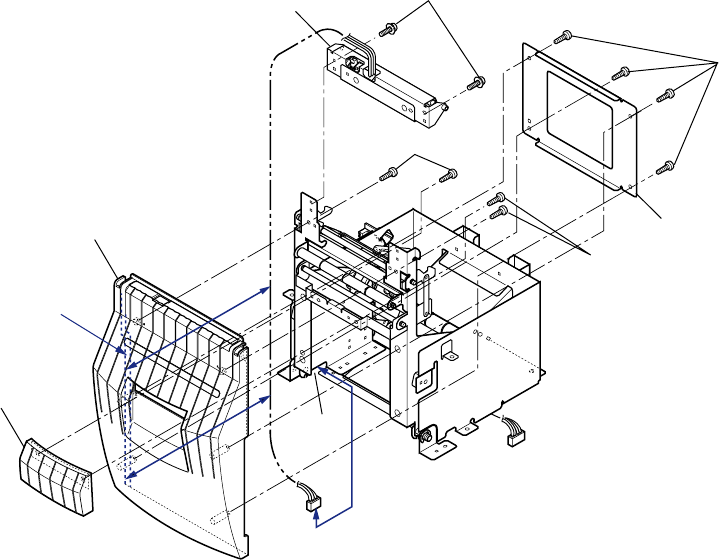
Chapter 3 Disassembly and Maintenance
3-5. Disassembly, Reassembly and Lubrication
3-37 CL-S700/CL-S703/CL-S700R
(3) Removing the “Door, Rewinder” and “SA1, Peeler”
1. Remove the Rewinder Mechanism block referring to above “(2) Removing the Rewinder
Mechanism block”.
Note: To remove the “Door, Rewinder” alone, it is not necessary to detach the Rewinder
Mechanism block. You can remove it after opening the Rewinder cover.
2. Remove 4 screws (PHT (#2), M3x6) and detach the “Frame2, Door Center”.
3. Remove 4 screws (PHT (#2), M3x6) and detach the Handle and Rewinder Door.
Note on reassembling:
• When attaching the “Door, Rewinder”, run the Peel sensor cable along the door frame
as shown in the figure (See the “Cable path”).
4. Remove 2 screws (PH (SW+PW), M3x5) and detach the “SA1, Peeler”.
Note on reassembling:
• Pass the cable (J503) through the left opening “A” as shown in the figure.
Door, Rewinder
Handle
SA1, Peeler PH (SW+PW), M3x5
PHT (#2), M3x6
PHT (#2), M3x6
PHT (#2), M3x6
(To J503)
(To J504)
(Cable path)
(Cable path)
Frame2, Door Center
A
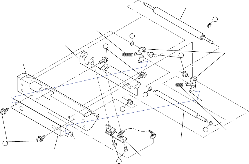
Chapter 3 Disassembly and Maintenance
3-5. Disassembly, Reassembly and Lubrication
CL-S700/CL-S703/CL-S700R 3-38
(4) Removing the “SA, Peel Sensor”/Friction Roller/Idle Rewinder Roller
1. Remove the “SA1, Peeler” referring to above “(3) Removing the “Door, Rewinder” and “SA1,
Peeler””.
2. Remove 2 screws (1BH, M3x5) and detach the “Plate, Friction Peeler”.
Then, the edges “A” of “Plate, Friction Link” on both sides are set free as they come off the
slits “B”, and both “Plate, Friction Link” become loose.
3. Remove 2 “Bush, Friction” (2) and detach the “Roller, Friction”.
4. Remove 2 screws (3PH, M2x3) and detach the “SA, Peel Sensor”.
5. Remove 3 “Bush, Idle” (4), 1 “Bush, Friction” (2), 2 “Plate, Friction Link”, “Spring, R
Friction” and “Spring, L Friction”, and detach the “Roller, Idle Rewinder”.
6. Disengage 1 E-ring (6E-Ring, 2) from the “Roller, Idle Rewinder”.
7. Remove 2 screws (7PH (SW+PW), M3x5) and detach the “Plate, Sensor Holder” from the
“Plate1, Peeler”.
Notes on reassembling:
• Distinguish the “Spring, L Friction” from “Spring, R Friction” referring to above figure.
The former is longer than the latter.
• Securely insert the edges “A” of the “Plate, Friction Link” into the slits “B”.
Roller, Idle Rewinder
1
2
3
Plate, Friction Peeler
2
Roller, Friction
4
SA, Peel Sensor
6
4
5
Plate, Friction Link
Spring, L Friction
Spring, R Friction
Plate, Sensor Holder
7
Plate1, Peeler
A
A’
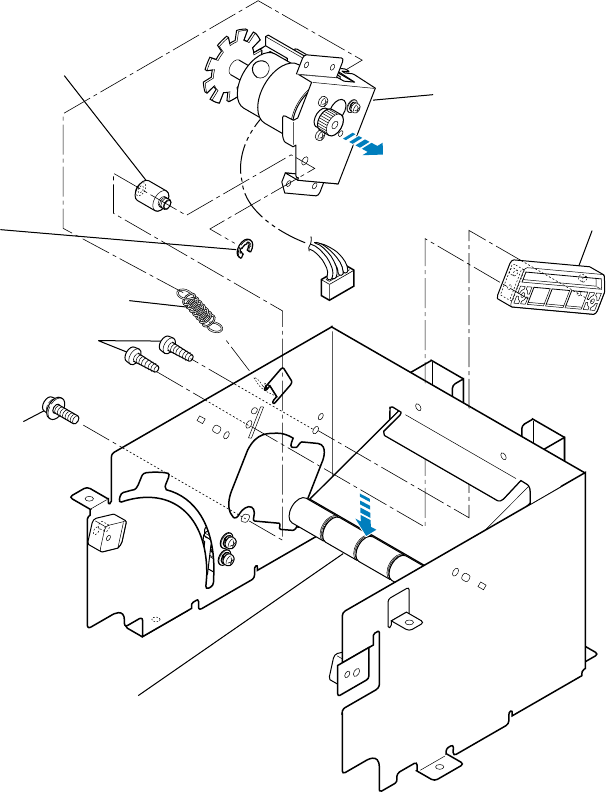
Chapter 3 Disassembly and Maintenance
3-5. Disassembly, Reassembly and Lubrication
3-39 CL-S700/CL-S703/CL-S700R
(5) Removing the “SA, Rewinder Motor”
1. Remove the Rewinder Mechanism block referring to “(2) Removing the Rewinder
Mechanism block”.
2. Remove 2 screws (PHT (#2), M3x6) and detach the “Guide, Motor Plate”.
3. Unhook the “Spring, Rewinder Motor”, disengage 1 E-ring (E-Ring, 3), remove 1 screw (PH
(SW+PW), M3x5), and detach the “Pivot, Rewinder Motor Plate”.
4. While pushing down the Measure Flap block, remove the “SA, Rewinder Motor” to the right.
Note on reassembling:
• After assembling the “SA, Rewinder Motor” on the frame, be sure that it can smoothly turn.
(The pivot is the supporting point of the “SA, Rewinder Motor”.)
PHT (#2), M3x6
Guide, Motor Plate
SA, Rewinder Motor
E-Ring, 3
Pivot, Rewinder Motor Plate
Spring, Rewinder Motor
PH (SW+PW), M3x5
(Measure Flap Block)
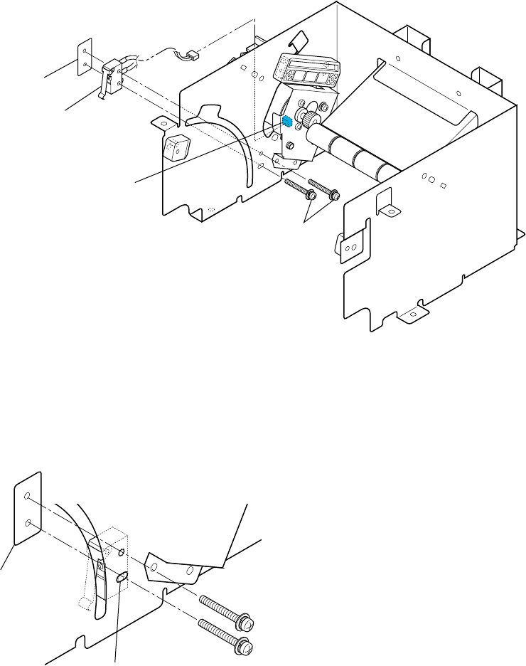
Chapter 3 Disassembly and Maintenance
3-5. Disassembly, Reassembly and Lubrication
CL-S700/CL-S703/CL-S700R 3-40
(6) Removing the “SA, Interlock SW”
1. Remove the Rewinder Mechanism block referring to “(2) Removing the Rewinder
Mechanism block”.
2. Disconnect the cable of the “SA, Interlock SW” from the “SA, Rewinder Motor”.
3. Remove 2 screws (PH (PW), M2x10) and detach the “Plate, Nut” and the “SA, Interlock
SW”.
Note on reassembling:
• Horizontal long hole is provided for mounting the lower side of the “SA, Interlock SW”.
When assembling the “Plate, Nut”, be sure that the lower side of screw is at the center of the
long hole as shown in the figure.
SA, Interlock SW
Connector of the
SA, Rewinder Motor
PH (PW), M2x10
Plate, Nut
Long hole
Plate, Nut
Chapter 3 Disassembly and Maintenance
3-5. Disassembly, Reassembly and Lubrication
3-41 CL-S700/CL-S703/CL-S700R
(7) Removing Rollers
Note: The parts location Nos. (e.g. [2-61]) show the ones for CL-S700R. Refer to the Drawing
No. 2 “Unit, Rewinder” for the Rewinder Part in Chapter 5 “Parts List”.
(7-1) Measure Sensor Rollers (4 pcs.)
1. Remove the Rewinder Mechanism block referring to “(2) Removing the Rewinder
Mechanism block”.
2. Disengage 2 E-rings (E-Ring, 3) [2-61] on both sides and pull out the “Shaft, Damper” [2-6]
to remove 4 “Roller, Measure Sensor” [2-7].
(7-2) Damper Roller (3 pcs.) of the Rewinder Cover block
1. Open the Rewinder Cover.
2. Disengage 2 E-rings (E-Ring, 3) [2-61] on both sides and pull out the “Shaft, Damper” [2-6]
to remove 3 “Roller, Damper” [2-22].
(7-3) Damper Roller (4 pcs.) of the Rewinder Mechanism block
1. Remove the Rewinder Door referring to “(3) Removing the “Door, Rewinder” and “SA1,
Peeler””.
2. Disengage 2 E-rings (E-Ring, 3) [2-61] on both sides and pull out the “Shaft, Guide
Roller ”[2-21] to remove 4 “Roller, Damper” [2-22].
(7-4) Peel Roll on the Printer part
1. Open the Rewinder Cover.
2. Remove 2 screws (PH (SW+PW), M3x5) [1-49] and detach the “SA2, Peeler” [1-45].
3. Disengage 1 E-ring (E-Ring, 4) [4-9], remove the “Bushing2, Peel Roller” [4-8], and pull out
the “Roll, Peel” [4-1].
(8) Removing “SA, Rewinder PCB”
Note: The parts location Nos. (e.g. [2-59]) show the ones for CL-S700R. Refer to the Drawing
No. 2 “Unit, Rewinder” for the Rewinder Part in Chapter 5 “Parts List”.
1. Remove 4 connectors (J501, J502, J503 and J504) from the “SA, Rewinder PCB” [2-59].
2. Remove 4 screws (PH (PW+SW), M3x5) [2-64] and detach the “SA, Rewinder PCB” [2-59].
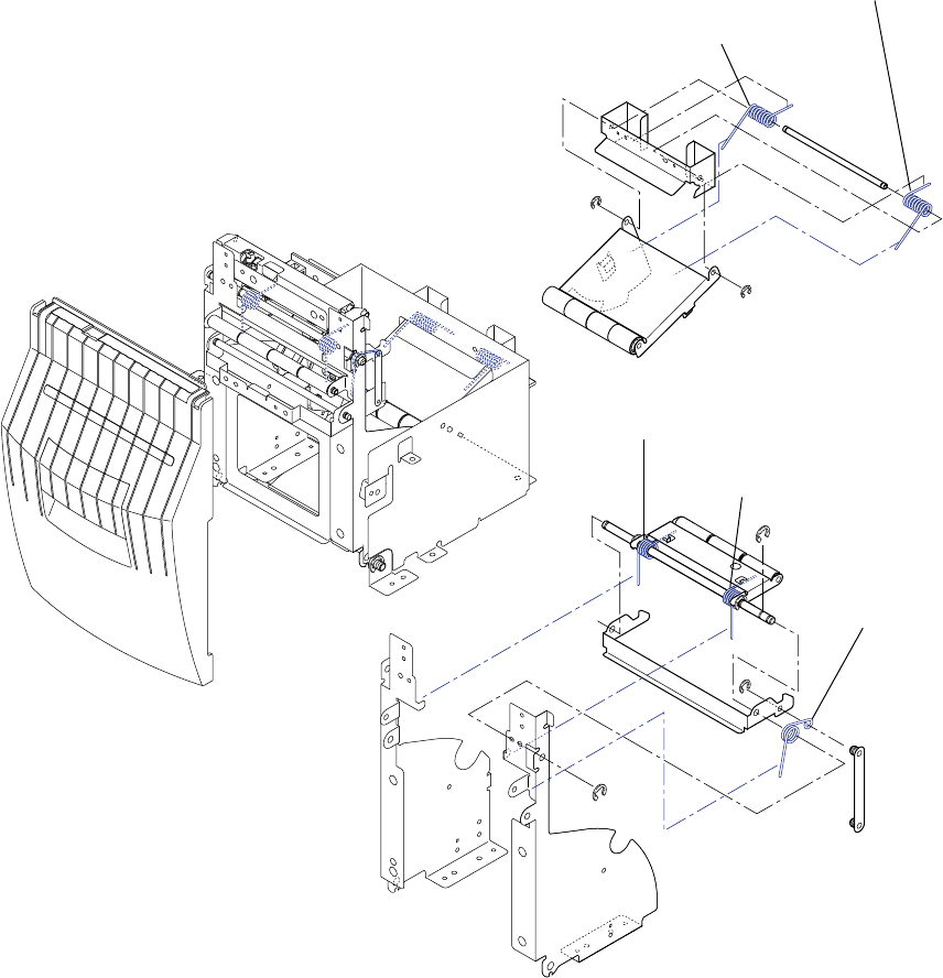
Chapter 3 Disassembly and Maintenance
3-5. Disassembly, Reassembly and Lubrication
CL-S700/CL-S703/CL-S700R 3-42
(9) Notes on assembling the springs
Note: The parts location Nos. (e.g. [2-2]) show the ones for CL-S700R. Refer to the Drawing
No. 2 “Unit, Rewinder” for the Rewinder Part in Chapter 5 “Parts List”.
The following figure shows the places where the springs should be assembled.
Assemble each spring correctly referring to the figure.
• “Spring, Measure Sensor L” [2-2]
• “Spring, Measure Sensor R“ [2-3]
• “Spring, Damper Rewinder L“ [2-23]
• “Spring, Damper Rewinder R“ [2-25]
• “Spring, Handle R“ [2-27]
Spring, Damper Rewinder L
Spring, Damper Rewinder R
Spring, Measure Sensor L
Spring, Measure Sensor R
Spring, Handle R
[Location of each spring]
Chapter 3 Disassembly and Maintenance
3-6. Adjustments
3-43 CL-S700/CL-S703/CL-S700R
3-6. Adjustments
3-6-1. Transparent/Reflective Sensor Position Adjustment
When you replace one of the following parts, perform both sensor position adjustment and sensor
sensitivity adjustment.”
• ”SA, Main PCB”
• ”SA, Sensor U” (Fixed type)
• ”SA, Sensor Bottom” (Fixed type)
• ”SA, Sensor U” (Adjustable type)
• ”SA, Sensor Bottom” (Adjustable type)
(1) Sensor position adjustment (Factory mode)
After entering Factory mode, adjust the following submenu items:
• Fix-Thru Pos (When “SA, Sensor U” (Fixed type) or “SA, Main PCB” is replaced.)
• Fix-Refl Pos (When “SA, Sensor Bottom” (Fixed type) or “SA, Main PCB” is replaced.)
• Adj-Thru Pos (When “SA, Sensor U” (Adjustable type) or “SA, Main PCB” is replaced.)
• Adj-Refl Pos (When “SA, Sensor Bottom” (Adjustable type) or “SA, Main PCB” is replaced.)
For details, refer to “2-3-4. Factory/Service mode” in Chapter 2.
(2) Sensor sensitivity adjustment (Factory mode)
- DO NOT adjust other submenus that are not explained here since the submenus in
Factory mode are essential items that can affect to the printing accuracy, etc.
- Do not turn OFF the power of the printer until you finish the adjustment. If it is
turned OFF, you need to repeat the adjustment from the beginning.
- The value adjusted here is retained until you change it with the same
procedure. Even if you perform initialization by selecting “Test Mode” main
menu, “Factory Default” submenu and “Yes”, the changed value is not
returned to the initial value set at the factory.
Perform sensitivity adjustment for each sensor with the following submenu.
Submenu Adjust when the following part is replaced. Refer to
Init Fix-Thru ”SA, Sensor U” (Fixed type) or ”SA, Main PCB” (2-1)
Init Fix-Refl ”SA, Sensor Bottom” (Fixed type) or ”SA, Main PCB” (2-2)
Init Adj-Thru ”SA, Sensor U” (Adjustable type) or ”SA, Main PCB” (2-3)
Init Adj-Refl ”SA, Sensor Bottom” (Adjustable type) or ”SA, Main PCB” (2-4)
Refer to “2-3-4. Factory/Service mode” in Chapter 2 for menu operation in Factory mode.
Caution

Chapter 3 Disassembly and Maintenance
3-6. Adjustments
CL-S700/CL-S703/CL-S700R 3-44
(2-1) Init Fix-Thru sensitivity adjustment
Init Fix-Thru sensor is the transparent sensor (fixed type), i.e. “SA, Sensor U” (Fixed type).
Preparation:
1. Prepare recommended media or media to be used.
2. Peel off labels from the liner.
3. Open the head block and the sensor arm, and then set the media.
4. Be sure that the media is put on the “SA, Sensor Bottom” (Fixed type). If the media
has black mark, avoid that area.
5. Close the sensor arm and the head block.
Procedure:
1. Enter Factory/Service mode by turning on the power while pressing and holding the
[MENU], [FEED] and [STOP] keys.
“Factory Setup” main menu appears.
2. In “Factory Setup” main menu, press the [STOP] (X) key to enter Factory Setup mode.
The first submenu “Sens Vol Adj.” appears.
3. Press the [MENU] (T) key until “Init Fix-Thru” submenu appears.
4. Press the [STOP] (X) key to enter Init Fix-Thru sensitivity adjustment mode.
5. Press the [MENU] (T) key to select “Exec”.
6. Press the [STOP] (X) key to execute adjustment.
Adjustment starts and the following screen is display. (Media is not fed.)
W X
Init Fix-Thru
No
Exit
Enter
S T
W X
Init Fix-Thru
Exec
Exit
Enter
S T
W X
Now !!
Executing
Exit
Enter
S T
W X
Factory Setup
Init Fix-Thru
Exit
Enter
S T

Chapter 3 Disassembly and Maintenance
3-6. Adjustments
3-45 CL-S700/CL-S703/CL-S700R
7. Be sure that adjustment is successfully completed and the following screen is
displayed. (The value “123” is an example.)
When adjustment failed:
“Cannot Setup” is displayed. In this case, follow the next steps.
1) Press any key of the printer.
The screen returns to that in Step 3.
2) Check for correct media setting position, media, active
sensor (Sensor Select menu is set to “Front Fixed Sen”),
etc. and repeat from Step 3.
8. Press any key of the printer.
Then, the obtained value is saved into the printer and the screen returns to Step 3.
9. To continue other adjustment, proceed to the desired item ((2-2), (2-3) or (2-4)).
To terminate adjustment, go to the next step.
10. Press the [PAUSE] (W) key to return to “Factory Setup” menu.
11. Press the [PAUSE] (W) key once again.
The changed value is stored in the printer and the printer is turned OFF and then ON
for normal operation.
W X
Finished
DAC 123
Exit
Enter
S T
W X
Cannot
Setup
Exit
Enter
S T

Chapter 3 Disassembly and Maintenance
3-6. Adjustments
CL-S700/CL-S703/CL-S700R 3-46
(2-2) Init Fix-Refl sensitivity adjustment
Init Fix-Refl sensor is the reflective sensor (fixed type), i.e. “SA, Sensor Bottom” (Fixed
type).
Preparation:
Open the head block and the sensor arm, and then set label with black mark or tag with
black mark.
When label with black mark is used:
1. Prepare recommended media or media to be used.
2. Peel off labels from the liner.
3. Set the media and be sure that the media is put on the “SA, Sensor Bottom” (Fixed
type) (avoid the black mark area).
4. Close the sensor arm and the head block.
When tag with black mark is used:
1. Prepare recommended media or media to be used.
2. Set the media (if continuous tag is used, set it) and be sure that the media is put on the
“SA, Sensor Bottom” (Fixed type) (avoid the black mark area).
3. Close the sensor arm and the head block.
Procedure:
1. Enter Factory/Service mode by turning on the power while pressing and holding the
[MENU], [FEED] and [STOP] keys.
“Factory Setup” main menu appears.
2. In “Factory Setup” main menu, press the [STOP] (X) key to enter Factory Setup mode.
The first submenu “Sens Vol Adj.” appears.
3. Press the [MENU] (T) key until “Init Fix-Refl” submenu appears.
4. Press the [STOP] (X) key to enter Init Fix-Refl sensitivity adjustment mode.
5. Press the [MENU] (T) key to select “Exec”.
W X
Init Fix-Refl
No
Exit
Enter
S T
W X
Init Fix-Refl
Exec
Exit
Enter
S T
W X
Factory Setup
Init Fix-Refl
Exit
Enter
S T

Chapter 3 Disassembly and Maintenance
3-6. Adjustments
3-47 CL-S700/CL-S703/CL-S700R
6. Press the [STOP] (X) key to execute adjustment.
Adjustment starts and the following screen is display. (Media is not fed.)
7. Be sure that adjustment is successfully completed and the following screen is
displayed. (The value “123” is an example.)
When adjustment failed:
“Cannot Setup” is displayed. In this case, follow the next steps.
1) Press any key of the printer.
The screen returns to that in Step 3.
2) Check for correct media setting position, media, active
sensor (Sensor Select menu is set to “Front Fixed Sen”),
etc. and repeat from Step 3.
8. Press any key of the printer.
Then, the obtained value is saved into the printer and the screen returns to Step 3.
9. To continue other adjustment, proceed to the desired item ((2-1), (2-3) or (2-4)).
To terminate adjustment, go to the next step.
10. Press the [PAUSE] (W) key to return to “Factory Setup” menu.
11. Press the [PAUSE] (W) key once again.
The changed value is stored in the printer and the printer is turned OFF and then ON
for normal operation.
W X
Now !!
Executing
Exit
Enter
S T
W X
Finished
DAC 123
Exit
Enter
S T
W X
Cannot
Setup
Exit
Enter
S T

Chapter 3 Disassembly and Maintenance
3-6. Adjustments
CL-S700/CL-S703/CL-S700R 3-48
(2-3) Init Adj-Thru sensitivity adjustment
Init Adj-Thru sensor is the transparent sensor (adjustable type), i.e. “SA, Sensor U”
(Adjustable type).
Preparation:
1. Prepare recommended media or media to be used.
2. Peel off labels from the liner.
3. Open the head block and the sensor arm, and then set the media.
4. Be sure that the media is put on the “SA, Sensor Bottom” (Adjustable type). If the
media has black mark, avoid that area.
5. Close the sensor arm and the head block.
Procedure:
1. Enter Factory/Service mode by turning on the power while pressing and holding the
[MENU], [FEED] and [STOP] keys.
“Factory Setup” main menu appears.
2. In “Factory Setup” main menu, press the [STOP] (X) key to enter Factory Setup mode.
The first submenu “Sens Vol Adj.” appears.
3. Press the [MENU] (T) key until “Init Adj-Thru” submenu appears.
4. Press the [STOP] (X) key to enter Init Adj-Thru sensitivity adjustment mode.
5. Press the [MENU] (T) key to select “Exec”.
6. Press the [STOP] (X) key to execute adjustment.
Adjustment starts and the following screen is display. (Media is not fed.)
W X
Init Adj-Thru
No
Exit
Enter
S T
W X
Init Adj-Thru
Exec
Exit
Enter
S T
W X
Now !!
Executing
Exit
Enter
S T
W X
Factory Setup
Init Adj-Thru
Exit
Enter
S T

Chapter 3 Disassembly and Maintenance
3-6. Adjustments
3-49 CL-S700/CL-S703/CL-S700R
7. Be sure that adjustment is successfully completed and the following screen is
displayed. (The value “123” is an example.)
When adjustment failed:
“Cannot Setup” is displayed. In this case, follow the next steps.
1) Press any key of the printer.
The screen returns to that in Step 3.
2) Check for correct media setting position, media, active
sensor (Sensor Select menu is set to “Rear Adj Sensor”),
etc. and repeat from Step 3.
8. Press any key of the printer.
Then, the obtained value is saved into the printer and the screen returns to Step 3.
9. To continue other adjustment, proceed to the desired item ((2-1), (2-2) or (2-4)).
To terminate adjustment, go to the next step.
10. Press the [PAUSE] (W) key to return to “Factory Setup” menu.
11. Press the [PAUSE] (W) key once again.
The changed value is stored in the printer and the printer is turned OFF and then ON
for normal operation.
W X
Finished
DAC 123
Exit
Enter
S T
W X
Cannot
Setup
Exit
Enter
S T

Chapter 3 Disassembly and Maintenance
3-6. Adjustments
CL-S700/CL-S703/CL-S700R 3-50
(2-4) Init Adj-Refl sensitivity adjustment
Init Adj-Refl sensor is the reflective sensor (adjustable type), i.e. “SA, Sensor Bottom”
(Adjustable type).
Preparation:
Open the head block and the sensor arm, and then set label with black mark or tag with
black mark.
When label with black mark is used:
1. Prepare recommended media or media to be used.
2. Peel off labels from the liner.
3. Set the media and be sure that the media is put on the “SA, Sensor Bottom”
(Adjustable type) (avoid the black mark area).
4. Close the sensor arm and the head block.
When tag with black mark is used:
1. Prepare recommended media or media to be used.
2. Set the media (if continuous tag is used, set it) and be sure that the media is put on the
“SA, Sensor Bottom” (Adjustable type) (avoid the black mark area).
3. Close the sensor arm and the head block.
Procedure:
1. Enter Factory/Service mode by turning on the power while pressing and holding the
[MENU], [FEED] and [STOP] keys.
“Factory Setup” main menu appears.
2. In “Factory Setup” main menu, press the [STOP] (X) key to enter Factory Setup mode.
The first submenu “Sens Vol Adj.” appears.
3. Press the [MENU] (T) key until “Init Adj-Refl” submenu appears.
4. Press the [STOP] (X) key to enter Init Adj-Refl sensitivity adjustment mode.
5. Press the [MENU] (T) key to select “Exec”.
W X
Init Adj-Refl
No
Exit
Enter
S T
W X
Init Adj-Refl
Exec
Exit
Enter
S T
W X
Factory Setup
Init Adj-Refl
Exit
Enter
S T

Chapter 3 Disassembly and Maintenance
3-6. Adjustments
3-51 CL-S700/CL-S703/CL-S700R
6. Press the [STOP] (X) key to execute adjustment.
Adjustment starts and the following screen is display. (Media is not fed.)
7. Be sure that adjustment is successfully completed and the following screen is
displayed. (The value “123” is an example.)
When adjustment failed:
“Cannot Setup” is displayed. In this case, follow the next steps.
1) Press any key of the printer.
The screen returns to that in Step 3.
2) Check for correct media setting position, media, active
sensor (Sensor Select menu is set to “Rear Adj Sensor”),
etc. and repeat from Step 3.
8. Press any key of the printer.
Then, the obtained value is saved into the printer and the screen returns to Step 3.
9. To continue other adjustment, proceed to the desired item ((2-1), (2-2) or (2-3)).
To terminate adjustment, go to the next step.
10. Press the [PAUSE] (W) key to return to “Factory Setup” menu.
11. Press the [PAUSE] (W) key once again.
The changed value is stored in the printer and the printer is turned OFF and then ON
for normal operation.
W X
Now !!
Executing
Exit
Enter
S T
W X
Finished
DAC 123
Exit
Enter
S T
W X
Cannot
Setup
Exit
Enter
S T
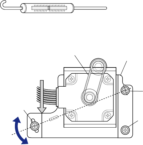
Chapter 3 Disassembly and Maintenance
3-6. Adjustments
CL-S700/CL-S703/CL-S700R 3-52
3-6-2. Belt Tension Adjustment
Belt tension adjustment is necessary in the following case.
- When the “Unit, Motor” is replaced.
1. Remove the screw “B” and loosely tighten the Motor block with 2 screws “A”.
2. Push the left side of the Motor block with the tip of the spring gauge as shown in the figure.
3. Push it so that the spring gauge reads the following value.
600 to 1000 gf.
4. Tighten the Motor block with 2 screws “A” and the screw “B”.
[Spring Gauge]
* Use Max. 2000gf gauge.
[Left side view of the “Unit, Mechanism”]
A
Belt, Motor Drive Motor Block
B
A
Spring Gauge
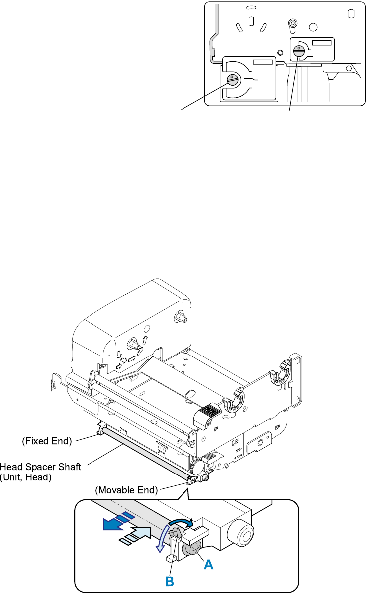
Chapter 3 Disassembly and Maintenance
3-6. Adjustments
3-53 CL-S700/CL-S703/CL-S700R
3-6-3. Ribbon Skew Adjustment
This adjustment may be necessary in the following case.
- When the “Unit, Head” is replaced
Normally, ribbon wrinkles can be removed by
adjusting the adjust screws of the “Unit, Ribbon
Frame L”. (Refer to the figure on the right.)
If ribbon wrinkles cannot be removed with these
screws, perform the ribbon skew adjustment as
follows:
Ribbon skew adjustment procedure:
Remove ribbon wrinkle by moving the right end (movable end) of the Head Spacer Shaft (a part of
the “Unit, Head”) as follows: (Left end is a fixed end.)
1. Loosen (not remove) the screw “A” of the Head Spacer Shaft.
2. Turn the lever “B” clockwise or counterclockwise to move the right side end of the Head Spacer
Shaft forward or backward to remove ribbon wrinkles. Refer to the figure below.
Also, refer to the figure on the next page to understand the ribbon skew adjustment
mechanism.
3. After adjustment, tighten the screw “A”.
TENSION
STANDARD
LOW
TENSION
STANDARD
LOW
SUPER LOW
Adjust screw for Take-up side
ribbon tension adjustment
Adjust screw for Supply side
ribbon tension adjustment
[On the left side of the Unit, Frame Ribbon L]
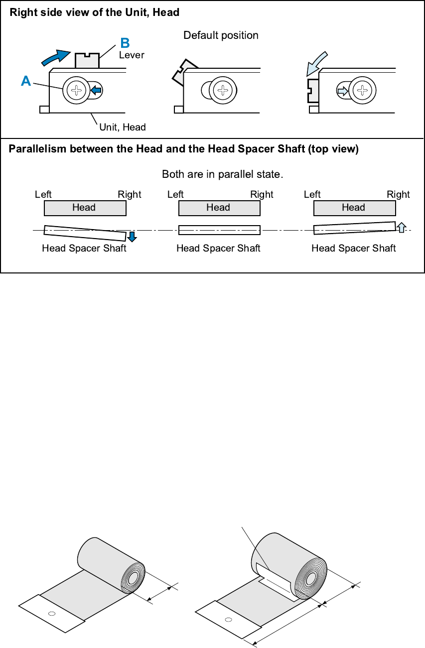
Chapter 3 Disassembly and Maintenance
3-6. Adjustments
CL-S700/CL-S703/CL-S700R 3-54
3-6-4. Ribbon Tension Adjustment
Perform the ribbon tension adjustment when the “Unit, Frame Ribbon L” is replaced with new one.
Preparation:
Make a “Ribbon-tension adjust ribbon” and “Ribbon-tension spring adjust ribbon” to be used in the
adjustment procedure.
Diameter of ribbons should be 60mm and 80mm, respectively.
Reinforce the ribbon end with paper or the like and punch a hole in the center as shown in the
figure.
As shown in the figure, stick a tape inside the “Ribbon-tension spring adjust ribbon (φ80mm)” at
about 150mm from the edge. (This tape acts to prevent the weight hooked on the ribbon hole from
falling to the floor. Without the tape, you cannot perform adjustment properly.)
[Ribbon-tension adjust ribbon] [Ribbon-tension spring adjust ribbon]
φ60mm
φ80mm
150mm
Tape
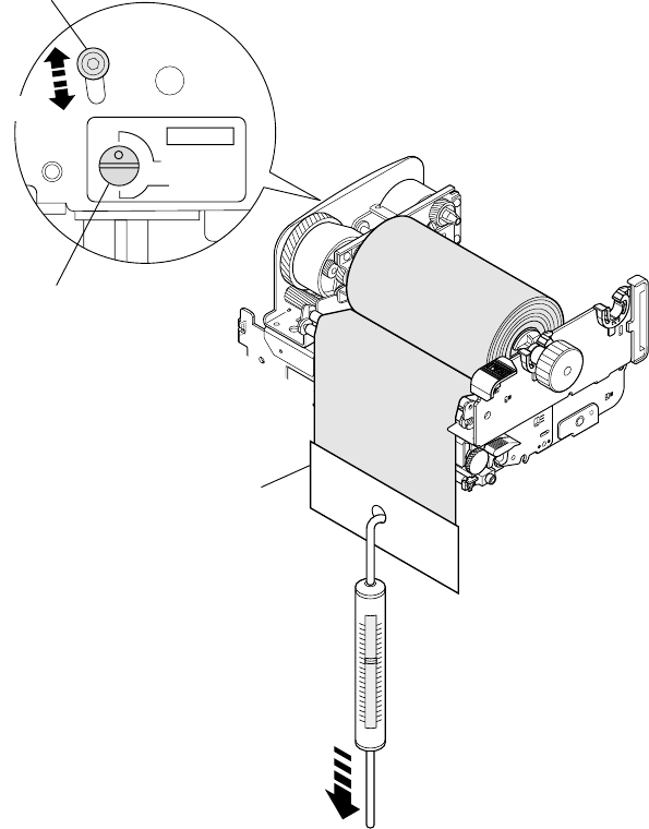
Chapter 3 Disassembly and Maintenance
3-6. Adjustments
3-55 CL-S700/CL-S703/CL-S700R
Adjustment procedure:
1. Remove the “SA, Ope-Pane”, “SA, Front Right” and “SA, Front Center” from the main body.
Refer to “3-5-8. Unit, Mechanism”.
2. Open the head block by pushing the head open lever and remove the “Unit, Head”.
Refer to “3-5-1. Unit, Head.
3. Remove the Ribbon Cover of the “Unit, Frame Ribbon L” form the “Unit, Mechanism”.
Refer to “3-5-12. Unit, Frame Ribbon L.
4. Ribbon Tension Check/Adjustment on Take-up Side:
1) Set the “Adjust screw for Take-up side ribbon tension adjustment” to “STANDARD”
position.
2) Set the “Ribbon-tension adjust ribbon (φ60mm)” to the take-up side ribbon holder.
3) Hook a spring gauge of 500gf on the “Ribbon-tension adjust ribbon” and slowly pull the
ribbon end downward at a constant speed (approx. 7.5cm/sec. or so). Then, check if the
reading of the spring gauge in the steady state is within 450 +/- 50gf.
If the reading is in the specified range, no tension adjustment is required on take-up side.
Proceed to step 5 “Ribbon Tension Check/Adjustment on Supply Side”.
If not, proceed to the next sub step.
TENSION
STANDARD
LOW
N
RD
Adjust screw for Take-up side
ribbon tension adjustment
Adjust screw "A" (For Service)
450 +/− 50gf
[Take-up side adjustment]
When weak
When stronge
Ribbon-tension adjust ribbon
(φ60mm)
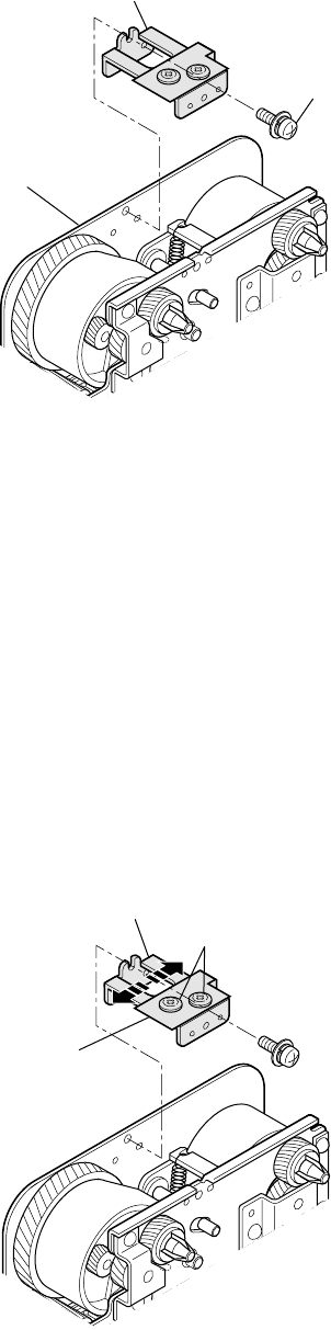
Chapter 3 Disassembly and Maintenance
3-6. Adjustments
CL-S700/CL-S703/CL-S700R 3-56
4) Detach the “Ribbon-tension adjust ribbon (φ60mm)” once and then remove the Ribbon
Tension Spring Block from the “Unit, Frame Ribbon L” by removing the screw “B”.
After that, reset the “Ribbon-tension adjust ribbon (φ60mm)”.
5) With the spring gauge of 500gf hooked on the “Ribbon-tension adjust ribbon”, repeat
above sub step 3) and be sure that the reading of the spring gauge is within 450 +/- 50gf.
If the reading is in the specified range, proceed to sub step 9).
If not, proceed to the next sub step.
6) Refer to the figure in sub step 3) and apply ThreeBond 1401B to the Adjust screw “A” after
removing it. Then, loosely tighten the Adjust screw “A” with a hex wrench and leave the
hex wrench on the Adjust screw “A”.
7) While repeating above sub step 3), adjust the position of Adjust screw “A” by moving hex
wrench up and down so that the reading of spring gauge is within 450 +/- 50gf.
Note: If tension is weak, move the Adjust screw “A” upward. If it is strong, move the Adjust
screw “A” downward.
8) After completion of adjustment, tighten the Adjust screw “A”.
9) Loosen (do not remove) the two screws “C” of the Ribbon Tension Spring Block to set the
Ribbon Tension Spring free.
B
Unit, Frame Ribbon L
(Ribbon Tension Spring Block)
C
(Ribbon Tension Spring Block)
Ribbon Tension Spring
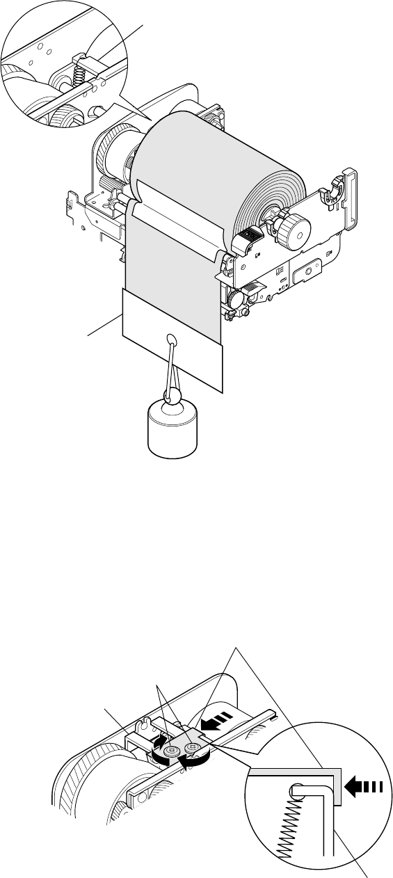
Chapter 3 Disassembly and Maintenance
3-6. Adjustments
3-57 CL-S700/CL-S703/CL-S700R
10) Hook a weight of 450g on the “Ribbon-tension spring adjust ribbon (φ80mm)”.
The Front Belt Plate moves and stops at a certain position where it balances with the
weight.
11) Mount the Ribbon Tension Spring Block and set the Ribbon Tension Spring so that no gap
is found between the Front Belt Plate. Then, apply ThreeBond 1401B to the screws “C”
and tighten the screws “C”.
Notes: • Do not move the Front Belt Plate.
• When tightening the screws “C”, pay special attention so as not to turn the
Ribbon Tension Spring.
• Be sure that the Ribbon Tension Spring is fully contact with the Front Belt Plate.
Ribbon Tension Spring
C
Apply ThreeBond 1401B.
Plate, Front Belt
(Ribbon Tension Spring Block)
450g
Plate, Front Belt
Ribbon-tension spring
adjust ribbon (φ80mm)
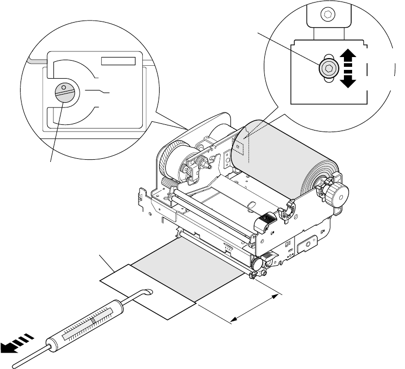
Chapter 3 Disassembly and Maintenance
3-6. Adjustments
CL-S700/CL-S703/CL-S700R 3-58
12) Remove the “Ribbon-tension spring adjust ribbon (φ80mm)” and reset the “Ribbon-tension
adjust ribbon (φ60mm)”.
13) Hook a spring gauge of 500gf on the “Ribbon-tension adjust ribbon (φ60mm)” and slowly
pull the ribbon end downward at a constant speed (approx. 7.5cm/sec. or so). Then, check
if the reading of the spring gauge in the steady state is within 450 +/- 50gf.
If the reading is out of the specified range, repeat above sub steps 4) through 11).
5. Ribbon Tension Check/Adjustment on Supply Side:
1) Set the “Adjust screw for Supply side ribbon tension adjustment” to “STANDARD” position.
2) Set the “Ribbon-tension adjust ribbon (φ60mm)” to the supply side ribbon holder.
3) Hook a spring gauge of 500gf on the “Ribbon-tension adjust ribbon” and horizontally pull
the ribbon end toward you at a constant speed (approx. 7.5cm/sec. or so).
When the ribbon is drawn approx. more than 20cm, suddenly load applies to the spring
gauge. With this load condition, check if the reading of the spring gauge is within 400 +/-
50gf.
4) If the reading is in the specified range, no tension adjustment on supply side is required. In
this case, proceed to step 6. If not, proceed to the next sub step.
5) Apply ThreeBond 1401B to the Adjust screw “D” after removing it. Then, loosely tighten the
Adjust screw “D” with a hex wrench and leave the hex wrench on the Adjust screw “D”.
6) While repeating above sub step 3), adjust the position of Adjust screw “D” by moving hex
wrench up and down so that the reading of spring gauge is within 400 +/- 50gf.
TENSION
STANDARD
LOW
SUPER LOW
Adjust screw for Supply side
ribbon tension adjustment
400 +/- 50gf
Approx. 20cm
Ribbon-tension adjust ribbon (φ60mm)
Adjust screw "D"
(For Service)
[Supply side adjustment]
When strong
When weak
Chapter 3 Disassembly and Maintenance
3-6. Adjustments
3-59 CL-S700/CL-S703/CL-S700R
Note: If tension is weak, move the Adjust screw “D” downward. If it is strong, move the
Adjust screw “D” upward.
7) Tighten the Adjust screw “D”.
6. Repeat steps 1 to 3 in the reverse order to assemble the removed parts.

Chapter 4 Troubleshooting
CL-S700/CL-S703/CL-S700R
CHAPTER 4
TROUBLESHOOTING

Chapter 4 Troubleshooting
CL-S700/CL-S703/CL-S700R 4-2
Chapter 4 Troubleshooting
Table of Contents
4-1. Error Message and Corrective Actions ........................................................................... 4-3
4-2. Troubleshooting .............................................................................................................. 4-5
4-2-1. Problems in Powering Up the Printer ................................................................. 4-5
4-2-2. Media-feed Problems ......................................................................................... 4-6
4-2-3. Problems in Printing ........................................................................................... 4-7
4-2-4. Ribbon-feed Problem ......................................................................................... 4-8
4-2-5. Sensor Problems................................................................................................ 4-9
4-2-6. Operation Panel Problems ................................................................................. 4-13
4-2-7. Rewinder Problems (CL-S700R Only) ............................................................... 4-14
(1) Rewinding problem (CL-S700R Only) ....................................................... 4-14
(2) Rewinder sensor problem (CL-S700R Only) ............................................. 4-15
4-2-7. Connector Location .............................................................................................. 4-16

Chapter 4 Troubleshooting
4-1. Error Message and Corrective Actions
4-3 CL-S700/CL-S703/CL-S700R
4-1. Error Message and Corrective Actions
When an error occurs, the error condition will be displayed on the operation panel. The ERROR
LED flashes and the LCD shows the error contents.
In case of error, the printer enters off line except for the following errors.
- LCD: Alarm Head Hot
- LCD: Alarm PFMotor Hot
- LCD: Alarm Cutter Hot
Causes/Corrective Actions ERROR LED LCD
Head temperature - high temperature abnormality
• Printing stops temporarily.
Wait until the thermal head gets cool.
Flashing Alarm
Head Hot
Head temperature - low temperature abnormality
• Printing is impossible. Start printing after the
thermal head becomes warm.
Flashing Error
Head Cold
PF motor temperature abnormality
• Printing stops temporarily. Wait until the motor
gets cool.
Flashing Alarm
PFMotor Hot
Fan motor malfunction
• Remove obstacle, if any.
• Firmly connect the cable (J12 on “SA, Main
PCB”).
• Replace the “SA, Fan”.
Flashing Error
Fan Lock
Cutter motor temperature abnormality (Option)
• Cutting action stops temporarily.
Wait until the cutter motor gets cool.
Flashing Alarm
Cutter Hot
Head open
• Close the head.
Flashing Error
Head Open
Paper end
• Add media.
Flashing Error
Paper End
Paper out (paper position undetectable)
• Incorrect Adjustable Sensor positioning:
Correct the sensor position to match the sensor
position with the label/tag’s black mark.
• Incorrect Media mode menu:
Match the Media mode menu (e.g. SeeThrough)
and media to be used.
(to be continued)
Flashing Error
Paper Load
• Incorrect sensor adjustment against media to be
used:
Enter sensor adjustment mode
While pressing [MENU], [FEED] and [STOP]

Chapter 4 Troubleshooting
4-1. Error Message and Corrective Actions
CL-S700/CL-S703/CL-S700R 4-4
Causes/Corrective Actions ERROR LED LCD
keys, turn on the power, and then perform
sensor adjustment.
For details, refer to 2-3-4 “(3) How to change the
settings in Factory mode” in Chapter 2.
Paper jam
• Remove the jammed media.
Flashing Error
Paper Jam
Head low resistance value abnormality
• Due to defective thermal element:
Printing quality will degrade.
Flashing Alarm
Head Check
Ribbon end
• Install a new ribbon.
Flashing Error
Ribbon End
Communication error
• Receiving buffer overrun error
Flashing Error
Serial Over Run
Communication error
• Parity error
Flashing Error
Serial Parity
Communication error
• Framing error
Flashing Error
Serial Framing
Cover open
• Close the printer cover.
Flashing Error
Cover Open
Auto-cutter abnormality (foreign object etc.)
• Jamming, etc.
Flashing Error
Cutter Fail
Rewinder cover open (CL-S700R only)
• Close the rewinder cover.
Flashing Error
Rewind Open
Rewinder full (CL-S700R only)
• Remove the wound media from the rewinder
flange.
Flashing Error
Rewind Full
Rewinder failure (CL-S700R only)
• Does not rewind, etc.
Flashing Error
Rewind Fail
Rewinder motor temperature abnormality
(CL-S700R only)
• Rewinding stops temporarily. Wait until the
motor gets cool.
Flashing Alarm
Rewinder Hot

Chapter 4 Troubleshooting
4-2. Troubleshooting
4-5 CL-S700/CL-S703/CL-S700R
4-2. Troubleshooting
The following tables show possible remedies for various symptoms that might occur. Symptoms
are given in the left column, and the corresponding remedies in the right column.
Notes:
1. When parts are replaced, refer to Chapter 3 "Disassembly and Maintenance".
2. Connectors (J . . .) given in the column of checks and remedies are connected with the “SA,
Main PCB”. For the location of each connector, refer to “4-2-7. Connector Location".
4-2-1. Problems in Powering Up the Printer
Symptoms Checks Remedies
No power to the
printer
1. Is the Power Cord loosely connected to
the AC outlet or the AC inlet of the
printer?
2. Check voltage on the input power line.
Acceptable supply voltage:
100 to 240V (-10%+6%)
3. Is the fuse F1 on the “Unit, Power
Supply” blown?
4. Is the connector of “SA, Power SW
Cable” firmly connected to the “Unit,
Power Supply” (CN1)?
5. Is the “SA, Power Cable” firmly
connected between the “Unit, Power
Supply” and the “SA, Main PCB” (J11)?
6. Is the Ope-pane Cable connected
between the “SA, Main PCB” (J14) and
the “SA, Ope-Pane PCB” firmly? If it is
not connected or is inserted upside
down, no LED lights up and nothing
appears on the LCD even if you turned
ON the power.
7. Failure in the power supply circuit.
1. Connect it firmly.
2. Supply correct voltage.
3. Replace with new fuse. If new fuse
is also blown when power is turned
on with the connector J11
disconnected from the “SA, Main
PCB”, the “Unit, Power Supply” is
faulty and must be replaced.
Notes:
- Do not replace the fuse with the
power switch turned on.
- The fuse is provided to prevent
fire, and damage to the “Unit,
Power Supply”. When replacing
it, use the same rating and type.
4. Connect it firmly.
5. Connect it firmly.
6. Connect it firmly.
7. Replace the “Unit, Power Supply”.

Chapter 4 Troubleshooting
4-2. Troubleshooting
CL-S700/CL-S703/CL-S700R 4-6
4-2-2. Media-feed Problems
Symptoms Checks Remedies
No media feed
1. Is the connector of the “SA, PF MTR
Cable” firmly connected to the “Unit,
Motor”?
2. Is the connector J4 for the “Unit, Motor”
connected firmly?
3. Is the connector J11 for “Unit, Power
Supply” connected firmly?
4. Is +24V supplied to pins 7, 8, 9 and 10
of J11?
5. Failure in the control circuit or in the
paper feed motor driver.
6. Does the “Unit, Motor” work?
1. Connect it firmly.
2. Connect it firmly.
3. Connect it firmly.
4. Replace the “Unit, Power Supply”.
5. Replace the “SA, Main PCB”.
6. Replace the “Unit, Motor”.
Irregular media feed
pitch
1. Is the connector J4 for PF motor
connected firmly?
2. Is dust or other foreign matter on the
platen?
3. Does the media feed mechanism work
smoothly?
4. Failure in the control circuit or in the
paper feed motor driver.
1. Connect it firmly.
2. Remove dust or foreign matter.
3. Check, clean and lubricate
mechanical parts.
Note: Refer to Chap. 3
"Disassembly and Maintenance".
4. Replace the “SA, Main PCB”.
Media jamming 1. Is media set correctly?
2. Is the media being used within
manufacturer's specifications?
3. Check the media feed mechanism and
media path for dust or other foreign
matter.
1. Set media correctly.
2. Use media within manufacturer's
specifications.
3. Remove dust or foreign matter.

Chapter 4 Troubleshooting
4-2. Troubleshooting
4-7 CL-S700/CL-S703/CL-S700R
4-2-3. Problems in Printing
Symptoms Checks Remedies
No print
1. Is the head block securely closed?
2. Is the thermal head over heated?
In this case, the LCD indicates “Alarm
Head Hot”.
3. Is the PF motor over heated?
In this case, the LCD indicates “Alarm
PFMotor Hot”.
4. Is the interface cable firmly connected
between the printer and the host?
5. Is the Centro cable firmly connected
between the “Unit, Centro PCB”
(CN101) and the “SA, Main PCB”
(J17)?
6. Is the “SA, Head Cable” firmly
connected between the “Unit, Head”
and the “SA, Main PCB” (J3)?
7. Does the transparent/reflective sensor
detect presence of media?
8. Is +24V supplied to pins 7, 8, 9 and 10
of J11?
9. Is the thermal head temperature too
low?
In this case, the LCD indicates “Error
Head Cold”.
10. “Unit, Head” is broken.
11. Failure in the head driver circuit.
12. Failure in the control circuit.
1. Close the head block correctly.
2. Wait until the thermal head gets
cool. Printing resumes
automatically.
3. Wait until the PF motor gets cool.
Printing resumes automatically.
4. Connect it firmly.
5. Connect it firmly.
6. Connect it firmly.
7. To check, see “4-2-5. Sensor
Problems".
8. Replace the “Unit, Power Supply”.
9. If the printer is cold, wait until it
gets warm. Otherwise, replace the
“Unit, Head”.
10. Replace the “Unit, Head” .
11. Replace the “Unit, Head” .
12. Replace the “SA, Main PCB”.
Poor printing
1. Thermal head is dirty.
2. Thickness adjustment is improper.
3. Is +24V supplied to pins 7, 8, 9 and 10
of J11?
1. Clean it with the head cleaner
provided.
2. Adjust the media thickness
adjustment screw to suit to the
media thickness being used.
3. Replace the “Unit, Power Supply”.
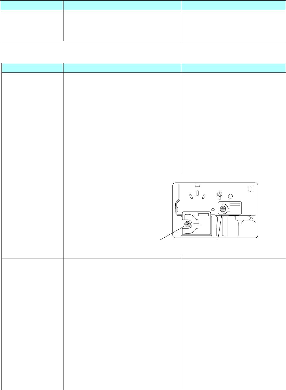
Chapter 4 Troubleshooting
4-2. Troubleshooting
CL-S700/CL-S703/CL-S700R 4-8
Symptoms Checks Remedies
Uneven print density 1. Head balance is improper.
Uneven print density may appear either
on the right side or the left side.
1. Adjust the media width adjustment
knob to suit to the media width
being used.
4-2-4. Ribbon-feed Problem
Symptoms Checks Remedies
Ribbon is not fed at
all, or is not fed
correctly.
1. Is the ribbon correctly inserted into the
ribbon holders?
2. Is the ribbon path correct?
3. Does the ribbon slack on the supply
side during back feeding?
4. Does the ribbon slack on the take-up
side during printing?
1. Insert the ribbon correctly.
2. Install the ribbon correctly.
3. Adjust the supply side ribbon
tension by turning the adjust screw
with a flat-bladed screwdriver.
4. Adjust the take-up side ribbon
tension by turning the adjust screw
with a flat-bladed screwdriver.
Ribbon wrinkles
occur.
1. Is proper ribbon tension applied to both
supply and take-up side?
2. Is printing density proper?
3. Head pressure does not match the
media width (ribbon width) being used.
4. Angle of the head spacer shaft of the
Head Unit is not proper.
(continued)
1. Adjust ribbon tension to suit to the
width of ribbon being used with the
Adjust screw for Supply/Take-up
side ribbon tension adjustment.
2. Set the printing density to an
appropriate value by using the
menu or control software.
3. Adjust the head pressure with the
media width adjustment knob.
4. Adjust the head spacer shaft angle
appropriately.
Refer to “3-6-3. Ribbon Skew
Adjustment” in Chapter 3.
TENSION
STANDARD
LOW
TENSION
STANDARD
LOW
SUPER LOW
Adjust screw for Take-up side
ribbon tension adjustment
Adjust screw for Supply side
ribbon tension adjustment
[On the left side of the Unit, Frame Ribbon L]

Chapter 4 Troubleshooting
4-2. Troubleshooting
4-9 CL-S700/CL-S703/CL-S700R
Symptoms Checks Remedies
Ribbon wrinkles
occur.
5. Has the “Unit, Frame Ribbon L” been
replaced with new one?
5. Perform the ribbon tension
adjustment.
Refer to “3-6-4. Ribbon Tension
Adjustment” in Chapter 3.
Ribbon tends to slip
on media. (May occur
faint printing,
displacement of
printing position, dirty
printing, etc.)
1. Is proper ribbon tension applied to both
supply and take-up side?
1. Adjust ribbon tension to suit to the
type and width of media.
Printing continues
even when ribbon
runs out.
1. Is the Print Method menu set to "DT"
(Direct Thermal) for thermal media
printing?
1. Change the Print Method menu to
"TT (Thermal Transfer)".
Ribbon slants.
1. Is the ribbon correctly inserted into the
ribbon holders?
2. Is the ribbon path correct?
1. Insert the ribbon correctly.
2. Install the ribbon correctly.
4-2-5. Sensor Problems
Symptoms Checks Remedies
Top cover is open,
but cover open status
is not detected (LCD
does not show “ Error
Cover Open”).
(Cover open sensor
problem)
1. Is the connector of the “SA, Cover
Open Sens” firmly connected to “SA,
Ope-pane PCB” (J403)?
2. Cover open sensor is defective.
3. Failure in the ope-pane circuit.
4. Replace the in the control circuit.
1. Connect it firmly.
2. Replace the “SA, Cover Open
Sens”.
3. Replace the “SA, Ope-pane PCB”.
4. Replace the “SA, Main PCB”.
Head block is closed,
but the LCD shows
“Error Head Open”.
(Head up sensor
problem)
1. Is the connector of the “SA, Head Up
SW” firmly connected to “SA, Main
PCB” (J9)?
2. Head up sensor is defective.
3. Failure in the control circuit.
1. Connect it firmly.
2. Replace the “SA, Head Up SW”.
3. Replace the “SA, Main PCB”.

Chapter 4 Troubleshooting
4-2. Troubleshooting
CL-S700/CL-S703/CL-S700R 4-10
Symptoms Checks Remedies
Ribbon end is not
correctly detected.
1. Is the connector of the ribbon encoder
in the “Unit, Frame Ribbon L” firmly
connected to the “SA, Main PCB” (J8)?
2. Ribbon encoder is defective.
3. Failure in the control circuit.
1. Connect it firmly.
2. Replace the “Unit, Frame Ribbon
L”.
After replacement, perform ribbon
tension adjustment referring to
“3-6-4. Ribbon Tension
Adjustment” in Chapter 3.
3. Replace the “SA, Main PCB”.
Label on liner or
notch of tag is not
detected.
(Transparent sensor
problem)
Or
Paper end is not
detected.
1. Is the Media Sensor menu setting
correct?
2. Is the Adjustable Sensor positioned to
an appropriate position where label or
notch of tag can be detected? (When
adjustable sensor is to be used)
By default, the Sensor Select menu is
set to “Rear Adj Sensor” and the
Adjustable Sensor is selected”.
3. Is the sensor adjustment performed
against media to be used?
4. Is the following connector of the “SA,
Sensor U” firmly connected to the “SA,
Main PCB”?
For Adjustable Sensor: J7
For Front Fixed Sensor: J6
5. Is the following connector of the “SA,
Sensor Bottom” firmly connected to the
“SA, Main PCB”?
For Adjustable Sensor: J22
For Front Fixed Sensor: J21
6. Is dust on the LED of the Transparent/
Reflective Sensor?
8. Failure in the Transparent Sensor or the
Reflective Sensor.
9. Failure in the control circuit.
1. Set it to “See Through”.
2. Move the Adjustable Sensor by
turning the adjustable sensor
position knob.
3. Perform the sensor adjustment for
user. See “Sensor Adjustment for
user (Transparent Sensor/
Reflective Sensor)” on the next
page.
4. Connect it firmly.
5. Connect it firmly.
6. Clean the LED to remove dust.
8. Replace the “SA, Sensor U” or the
“SA, Sensor Bottom”.
9. Replace the “SA, Main PCB”.

Chapter 4 Troubleshooting
4-2. Troubleshooting
4-11 CL-S700/CL-S703/CL-S700R
[Sensor Adjustment for user (Transparent Sensor/Reflective Sensor)]
The following describes the transparent and reflective sensor adjustment method (for user) for both
adjustable sensor and the front fixed sensor.
This method is stated in “Sensor Adjustments and Calibration” of the User’s Manual.
Preparation:
Transparent sensor:
1. Peel off labels from the liner.
2. Open the head block and the sensor arm, and set the media on the “SA, Sensor
Bottom” (Adjustable type) or “SA, Sensor Bottom” (Fixed type).
If the media has black mark, avoid that area.
3. Close the sensor arm and the head block.
Reflective sensor:
When label with black mark is used
1. Peel off labels from the liner.
2. Open the head block and the sensor arm, and set the media on the “SA, Sensor
Bottom” (Adjustable type) or “SA, Sensor Bottom” (Fixed type).
If the media has black mark, avoid that area.
3. Close the sensor arm and the head block.
When tag with black mark is used
1. Open the head block and the sensor arm, and set the media (if continuous tag is used,
set it) on the “SA, Sensor Bottom” (Adjustable type) or “SA, Sensor Bottom” (Fixed
type).
Avoid the black mark area.
2. Close the sensor arm and the head block.
Sensor Adjustment Procedure:
1. Turn on the power while pressing and holding the [PAUSE], [FEED] and [STOP] keys.
“Sensor Cal Mode See Through (or Reflect)” is displayed on the LCD.
(To switch between “See Through” and “Reflect”, press and release the [STOP] key
while pressing and holding the [MENU] key.
2. Press and release the [PAUSE] key while pressing and holding the [MENU] key.
“Sensor Cal Mode Executing” and then “Sensor Cal Mode Succeeded” will be
displayed on the LCD.
(If adjustment stops abnormally (adjustment impossible), the ERROR LED flashes and
"Failed" is displayed.)
3. Press the [STOP] key.
Then the printer turns off and then on again, and enters the normal operation.

Chapter 4 Troubleshooting
4-2. Troubleshooting
CL-S700/CL-S703/CL-S700R 4-12
Symptoms Checks Remedies
Black mark on tag is
not detected.
(Reflective sensor
problem)
Or
Paper end is not
detected.
1. Is the Media Sensor menu correct?
2. Is the Adjustable Sensor positioned to
an appropriate position where a black
mark on tag can be detected? (When
adjustable sensor is to be used)
3. Is the sensor adjustment is performed
against media to be used?
4. Is the following connector of the “SA,
Sensor Bottom” firmly connected to the
“SA, Main PCB”?
For Adjustable Sensor: J22
For Front Fixed Sensor: J21
5. Is dust on the LED or phototransistor of
the Reflective Sensor?
6. Failure in the Reflective Sensor.
7. Failure in the control circuit.
1. Set it to “Reflect”.
2. Move the Adjustable Sensor by
turning the adjustable sensor
position knob so that it is set to the
center of black mark.
3. Perform the sensor adjustment for
user. See “Sensor Adjustment for
user (Transparent Sensor/
Reflective Sensor)” on the next
page.
4. Connect it firmly.
5. Clean the LED/phototransistor to
remove dust.
6. Replace the “SA, Sensor Bottom”.
7. Replace the “SA, Main PCB”.

Chapter 4 Troubleshooting
4-2. Troubleshooting
4-13 CL-S700/CL-S703/CL-S700R
4-2-6. Operation Panel Problems
Symptoms Checks Remedies
LED does not light.
1. Is the Ope-pane FFC Cable connected
between the “SA, Main PCB” (J14) and
the “SA, Ope-Pane PCB” firmly?
2. Is the Ope-pane FFC Cable inserted
upside down?
3. Failure in the “SA, Ope-Pane PCB”.
4. Failure in the control circuit.
1. Connect it firmly.
2. Insert it in the correct direction.
3. Replace the “SA, Ope-Pane PCB”.
4. Replace the “SA, Main PCB”.
No key works.
1. Is the Ope-pane Cable connected
between the “SA, Main PCB” (J14) and
the “SA, Ope-Pane PCB” firmly?
2. Is the Ope-pane FFC Cable inserted in
the correct direction?
3. Failure in the ope-pane circuit.
4. Failure in the control circuit.
1. Connect it firmly.
2. Insert it in the correct direction.
3. Replace the “SA, Ope-Pane PCB”.
4. Replace the “SA, Main PCB”.
Nothing appears on
the LCD.
1. Is the Ope-pane Cable connected
between the “SA, Main PCB” (J14) and
the “SA, Ope-Pane PCB” firmly?
2. Is the Ope-pane FFC Cable inserted in
the correct direction?
3. On the “SA, Ope-Pane PCB”, is the
LCD FPC firmly inserted into the
connector J402?
4. Failure in the ope-pane circuit.
5. Failure in the control circuit.
1. Connect it firmly.
2. Insert it in the correct direction.
3. Connect it firmly.
4. Replace the “SA, Ope-Pane PCB”.
5. Replace the “SA, Main PCB”.

Chapter 4 Troubleshooting
4-2. Troubleshooting
CL-S700/CL-S703/CL-S700R 4-14
4-2-7. Rewinder Problems (CL-S700R Only)
(1) Rewinding problem (CL-S700R Only)
Symptoms Checks Remedies
Does not rewind. 1. Is the rewinder cover opened?
In this case, the LCD indicates “Error
Rewinder Open”.
2. Is the rewinder full?
In this case, the LCD indicates “Error
Rewinder Full”.
3. Is the rewinder motor over heated?
In this case, the LCD indicates “Alarm
Rewinder Hot”.
4. Are cables J15 and J16 (“SA, Main
PCB”) connected to J501 and J502
(“SA, Rewinder PCB”) firmly?
5. Is the connector of the “SA, Rewinder
Motor” connected to J504 of the “SA,
Rewinder PCB” firmly?
6. Is the connector of the “SA, Interlock
SW” connected to “SA, Rewinder
Motor” firmly?
In this case, the LCD indicates “Error
Rewinder Open”.
7. Failure in the “SA, Rewinder Motor”.
8. Failure in the “SA, Rewinder PCB”.
9. Failure in the control circuit.
1. Close the rewinder cover.
2. Remove the wound media from the
rewinder flange.
3. Wait until the rewind motor gets
cool. Rewinding resumes
automatically.
4. Connect them firmly.
5. Connect it firmly.
6. Connect it firmly.
7. Replace the “SA, Rewinder Motor”.
8. Replace the “SA, Rewinder PCB”.
9. Replace the “SA, Main PCB”.
Label is peeled but
rewinding operation
does not pause.
1. Is the peel sensor cable connected to
JP503 of the “SA, Rewinder PCB”
firmly?
2. Failure in the “SA, Rewinder PCB”.
3. Failure in the control circuit.
1. Connect it firmly.
2. Replace the “SA, Rewinder PCB”.
3. Replace the “SA, Main PCB”.

Chapter 4 Troubleshooting
4-2. Troubleshooting
4-15 CL-S700/CL-S703/CL-S700R
(2) Rewinder sensor problem (CL-S700R Only)
Symptoms Checks Remedies
Rewinder cover is
closed, but rewinder
cover open status is
detected.
(LCD shows “Error
Rewinder Open”.)
1. Rewinder cover sensor (“SA, Interlock
SW”) is defective.
2. Failure in the “SA, Rewinder Motor”.
3. Failure in the “SA, Rewinder PCB”.
4. Failure in the control circuit.
1. Replace the “SA, Interlock SW”.
2. Replace the “SA, Rewinder Motor”.
3. Replace the “SA, Rewinder PCB”.
4. Replace the “SA, Main PCB”.
Rewinder motor
rotation is not
detected.
(LCD shows “Error
Rewinder Fail”.)
1. Failure of photo interrupter PS701of the
“SA, Rewinder Motor”.
2. Failure in the “SA, Rewinder PCB”.
3. Failure in the control circuit.
1. Replace the “SA, Rewinder Motor”.
2. Replace the “SA, Rewinder PCB”.
3. Replace the “SA, Main PCB”.
Rewind Full status is
not detected or
rewinding speed is
not properly
controlled.
1. Failure of photo interrupter PS501/
PS502 of the “SA, Rewinder PCB”.
2. Failure in the control circuit.
1. Replace the “SA, Rewinder PCB”.
2. Replace the “SA, Main PCB”.
Peeled label is not
detected.
1. Failure of Peel Sensor.
2. Failure in the “SA, Rewinder PCB”.
3. Failure in the control circuit.
1. Replace the “SA, Peel Sensor”.
2. Replace the “SA, Rewinder PCB”.
3. Replace the “SA, Main PCB”.
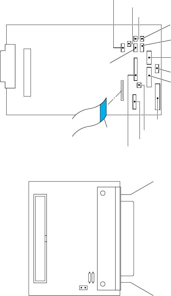
Chapter 4 Troubleshooting
4-2. Troubleshooting
CL-S700/CL-S703/CL-S700R 4-16
4-2-7. Connector Location
[SA, Main PCB]
[Unit, Centro PCB]
CN101
J16
J12
J6
J21
J7
J22
J11
J5
J4
J15
J3
J14
J9
J8
1
10
Unit, Head
SA, Main PCB
SA, Head Up SW (Head Up Sensor)
Adjustable Sensor (Transparent sensor)
Front Fixed Sensor
(Transparent sensor)
Adjustable Sensor
(Reflective sensor)
Front Fixed Sensor
(Reflective sensor)
SA, Fan
Unit, Motor
Unit, Motor (Thermistor)
Unit, Power Supply
Ope-Pane FFC Cable (Blue Tape)
Ribbon Encoder
(Ribbon Running Sensor/Ribbon End Sensor)
SA, Connect PCB (J801) (CL-S700/CL-S703)
SA, Rewinder PCB (J501) (CL-S700R)
SA, Connect PCB (J803) (CL-S700/CL-S703)
SA, Rewinder PCB (J502) (CL-S700R)
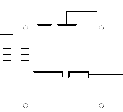
Chapter 4 Troubleshooting
4-2. Troubleshooting
4-17 CL-S700/CL-S703/CL-S700R
[SA, Rewinder PCB] (For CL-S700R)
J503 J504
J502J501
PS501 PS502
SA, Main PCB (J16)
SA, Main PCB (J15)
SA, Peel Sensor
SA, Rewinder Motor

Chapter 5 Parts Lists
CL-S700/CL-S703/CL-S700R
CHAPTER 5
PARTS LISTS
Note:
The Parts Lists section consists of the following two parts:
Former half: For CL-S700 and CL-S703
Latter half: For CL-S700R (Common parts with the printer upper area are to be
referred to the former half.)
Chapter 5 Parts Lists
CL-S700/CL-S703 5-2
Chapter 5 Parts Lists
for CL-S700/CL-S703
Table of Contents
Recommended Spare Parts List .............................................................................................. 5-3
Drawing No. 1 Parts List & Location for General Assembly ............................................... 5-5
Drawing No. 2 Parts List & Location for Unit, Mechanism.................................................. 5-10
Drawing No. 3 Parts List & Location for Unit, Frame U ...................................................... 5-14
Drawing No. 4 Parts List & Location for SA, Front Tension Arm ........................................ 5-18
Drawing No. 5 Parts List & Location for Unit, Frame Rear................................................. 5-21
Drawing No. 6 Parts List & Location for SA, Frame Ribbon R ........................................... 5-24
Drawing No. 7 Parts List & Location for SA, Base Guide Open ......................................... 5-27
Drawing No. 8 Parts List & Location for Unit, Sensor Adjust.............................................. 5-30
Drawing No. 9 Parts List & Location for Unit, Frame.......................................................... 5-34
Drawing No. 10 Parts List & Location for Unit, Top Cover.................................................... 5-39
Drawing No. 11 Parts List & Location for SA, Ope-pane...................................................... 5-42
Drawing No. 12 Parts List & Location for SA, Front Center ................................................. 5-45
Drawing No. 13 Parts List & Location for SA, Front Right.................................................... 5-48
Drawing No. 14 Parts List & Location for Unit, PCB............................................................. 5-51
Drawing No. - Parts List & Location for Accessories ......................................................... 5-54

Chapter 5 Parts Lists
5-3 CL-S700/CL-S703
CL-S700/CL-S703
Recommended Spare Parts List
Revision Up List
Sheet No. Rev. No. Date
1/1 1 Dec. 15, 2010

Chapter 5 Parts Lists
CL-S700/CL-S703 5-4
PARTS LIST for CL-S700/CL-S703 TITLE: Recommended Spare Parts List Sheet No. 1/1
Rev. No. 1
Maint. Class
Item
No. Location Part No. Part Name Q'ty/
Unit Worn Casual Remarks @
1 1-15 JN66801-0 Unit, Power Supply 1 |
2 2-8-1 JN09802-0 Unit, Head 1 |
For CL-S700/CL-S700R
(Rev. No.1)
3 2-8-2 JN09804-0 Unit, Head (300DPI) 1 | For CL-S703 (Rev. No.1)
4 8-9 JN48704-0 SA, Sensor U 1 | Adjustable type
5 8-24 JN48705-0 SA, Sensor Bottom 1 | Adjustable type
6 9-1 JN28801-0 Unit, Roller Platen 1 |
7 9-39 JN25801-0 Unit, Motor 1 |
8 9-7 JN48701-0 SA, Sensor U 1 | Fixed type
9 9-18 JN48702-0 SA, Sensor Bottom 1 | Fixed type
10 14-2-1 JN66701-0 SA, Main PCB (200) 1 | For CL-S700 (Rev. No.1)
11 14-2-2 JN66702-0 SA, Main PCB (300) 1 | For CL-S703 (Rev. No.1)
12 14-2-3 JN66718-0 SA, Main PCB (200R) 1 | For CL-S700R
(Rev. No.1)
13
14
15
16
17
18

Chapter 5 Parts Lists
5-5 CL-S700/CL-S703
CL-S700/CL-S703
Drawing No. 1
Parts List & Location for General Assembly
Revision Up List
Sheet No. Rev. No. Date
1/3 0 Apr. 18, 2008
2/3 0 Apr. 18, 2008
3/3 0 Apr. 18, 2008
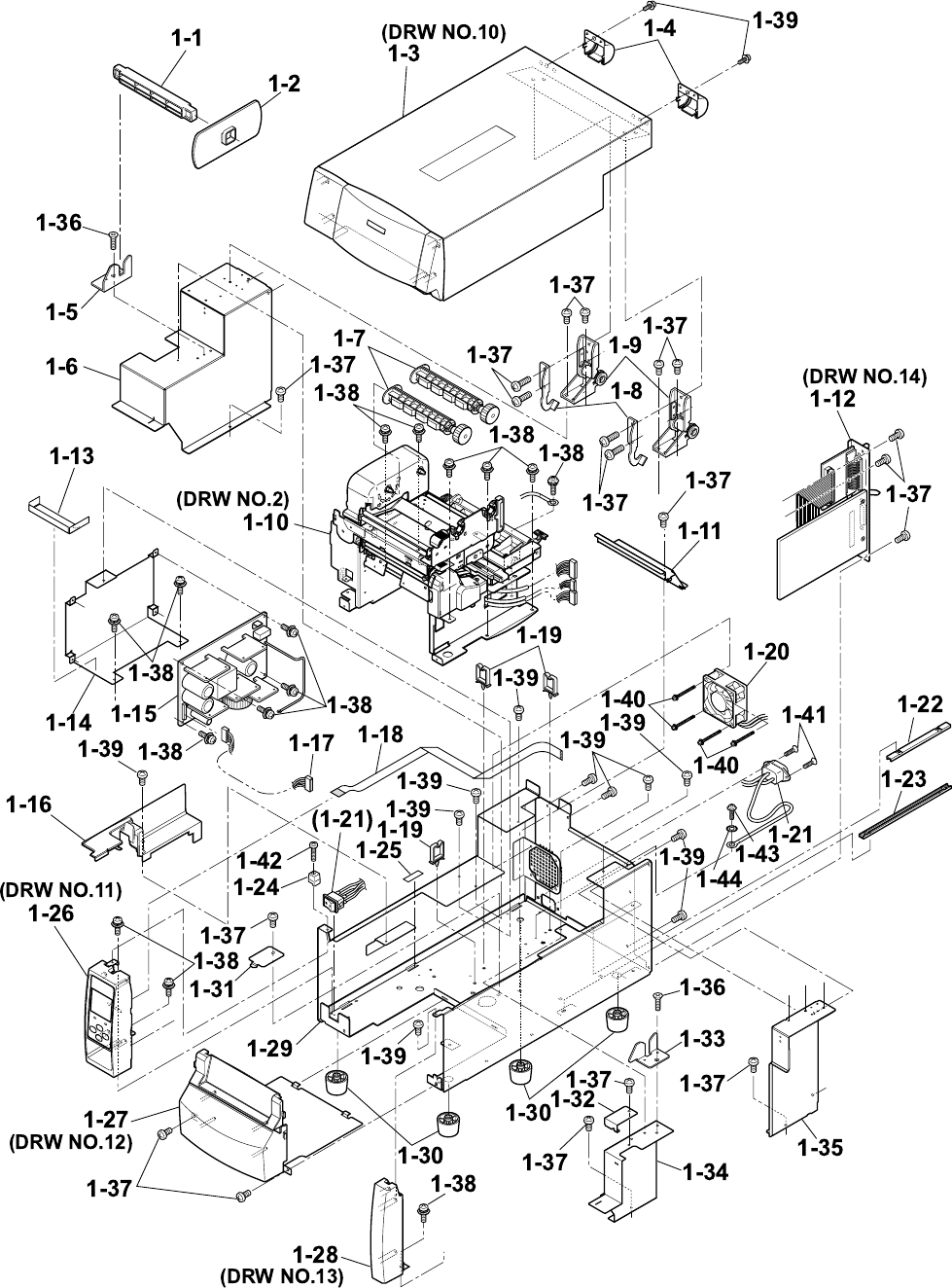
Chapter 5 Parts Lists
CL-S700/CL-S703 5-6
DRAWING NO. 1 General Assembly (Rev. 0) For CL-S700/CL-S703

Chapter 5 Parts Lists
5-7 CL-S700/CL-S703
PARTS LIST for CL-S700/CL-S703 TITLE: General Assembly Sheet No. 1/3
Drawing No. 1 Rev. No. 0
Location Part Name Part No. Q'ty/
Unit Remarks @
1-1 Roll Holder JE99090-0 1 24600730
1-2 Flange, Paper Wide JM79201-0 1
1-3 Unit, Top Cover ---- 1 Ref: Drawing No. 10
1-4 Cover, Hinge JN56209-0 2
1-5 Holder, Paper Shaft Left JN56116-0 1
1-6 SA, Cover Inner Power JN56704-0 1
1-7 SA, Ribbon Holder JM34710-1 2
1-8 Stopper, Hinge JN54103-0 2
1-9 SA, Hinge JN59905-0 2
1-10 Unit, Mechanism JN99801-0 1 Ref: Drawing No. 2
1-11 Cover, Inner Paper JN56112-0 1
1-12 Unit, PCB - 1 Ref.: Drawing No. 14
1-13 Sheet 1, Power Protect JN54910-0 1
1-14 Plate, Power JN64101-0 1
1-15 Unit, Power Supply JN66801-0 1
1-16 Cover, Cable JN56201-0 1
1-17 SA, Power Cable JN67706-0 1
1-18 Cable, Ope-pane FFC JN67901-0 1
1-19 WS-2NS (Cable, Clamp) JN59903-0 3
1-20 SA, Fan JN65901-0 1

Chapter 5 Parts Lists
CL-S700/CL-S703 5-8
PARTS LIST for CL-S700/CL-S703 TITLE: General Assembly Sheet No. 2/3
Drawing No. 1 Rev. No. 0
Location Part Name Part No. Q'ty/
Unit Remarks @
1-21 SA, Power SW Cable JN67709-0 1 Including Inlet
1-22 Rail, Guide U JN54906-0 1
1-23 Rail, Guide Base JN54907-0 1
1-24 Guide, Top Cover JN54202-0 1
1-25 Sheet, Case L JN54106-0 1
1-26 SA, Ope-pane JN56705-0 1 Ref.: Drawing No. 11
1-27 SA, Front Center JN56708-0 1 Ref.: Drawing No. 12
1-28 SA, Front Right JN56707-0 1 Ref.: Drawing No. 13
1-29 SA, Case L JN56701-1 1
1-30 Leg, Case JN56901-0 4
1-31 Plate, Cable Cover JN56113-0 1
1-32 Cover, Sensor Adjust JN56115-0 1
1-33 Holder, Paper Shaft Right JN56117-0 1
1-34 Cover, Inner PCB Front JN56110-0 1
1-35 SA, Cover Inner PCB Rear JN56713-0 1
1-36 Screw, FH, M3.0x6 E00230-060F 2
1-37 Screw, BH, M3.0x5 E00530-050F 19
1-38 Screw, PH (SW+PW), M3.0x5 E04030-050F 15
1-39 Screw, BH, M3.0x5K E00530-050KF 13
1-40 Screw, PH (SW+PW), M4.0x30 E00940-300F 4

Chapter 5 Parts Lists
5-9 CL-S700/CL-S703
PARTS LIST for CL-S700/CL-S703 TITLE: General Assembly Sheet No. 3/3
Drawing No. 1 Rev. No. 0
Location Part Name Part No. Q'ty/
Unit Remarks @
1-41 Screw, FH, M3.0x6 E00230-060F 2
1-42 Screw, PH, M3.0x12 E00130-120F 1
1-43 Screw, BH (N), M4.0x4 E00540-040WF 1
1-44 Washer, EXT, T (N), 4 E50740-000WF 1

Chapter 5 Parts Lists
CL-S700/CL-S703 5-10
CL-S700/CL-S703
Drawing No. 2
Parts List & Location for Unit, Mechanism
Revision Up List
Sheet No. Rev. No. Date
1/2 2 Dec. 15, 2010
2/2 1 Jan. 15, 2009
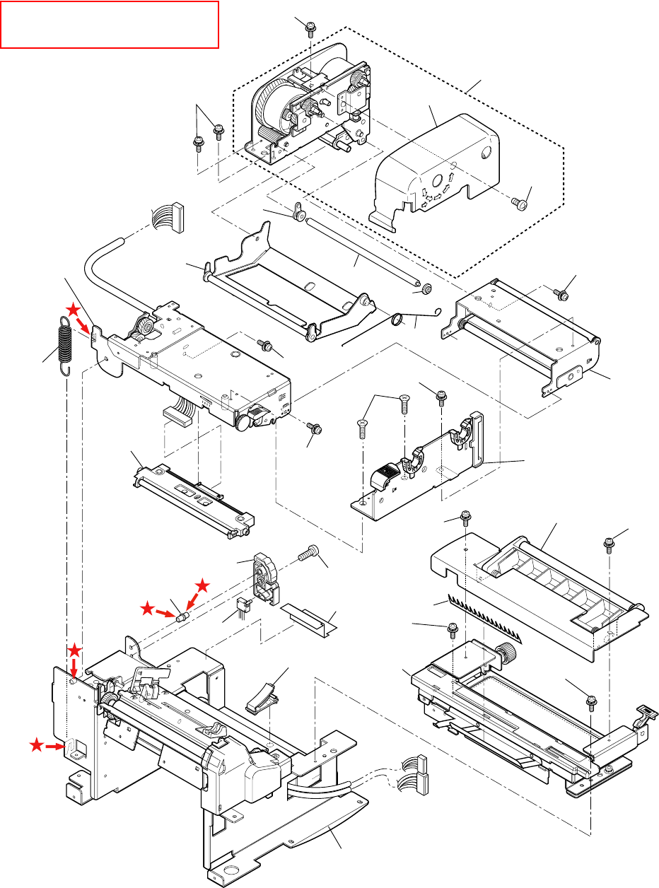
Chapter 5 Parts Lists
5-11 CL-S700/CL-S703
2-19
2-22
2-22 2-20
2-21
2-22
2-5
2-3
2-2
2-1
2-6
2-7
2-4
2-22
2-22
2-23 2-22
2-9
2-10 2-22
2-22
2-22
2-11
2-22
2-12
2-15 2-24
2-14
2-8-1
2-8-2
2-16
2-17
2-18
2-13
(DRW NO.5)
(DRW NO.6)
(DRW NO.7)
(DRW NO.8)
(DRW NO.9)
(DRW NO.4)
(DRW NO.3)
2-25
DRAWING NO. 2 Unit, Mechanism (Rev. 1) For CL-S700/CL-S703
Apply grease (Floil G-311S) to
the places marked with .

Chapter 5 Parts Lists
CL-S700/CL-S703 5-12
PARTS LIST for CL-S700/CL-S703 TITLE: Unit, Mechanism Sheet No. 1/2
Drawing No. 2 Rev. No. 2
Location Part Name Part No. Q'ty/
Unit Remarks @
2-1 Bushing JE99704-0 1 24400670
2-2 Shaft, Ribbon Guide FF JN32001-0 1
2-3 Bushing JE99705-0 1 24400680
2-4 SA, Front Tension Arm JN34704-0 1 Ref: Drawing No. 4
2-5 Unit, Frame Rear JN44803-0 1 Ref: Drawing No. 5
2-6 Unit, Frame U JN44802-0 1 Ref: Drawing No. 3
2-7 Spring, Head Up JN13601-0 1
2-8-1 Unit, Head JN09802-0 1 For CL-S700/CL-S700R (Rev. No.2)
2-8-2 Unit, Head (300DPI) JN09804-0 1 For CL-S703 (Rev. No.2)
2-9 SA, Frame Ribbon R JN34703-0 1 Ref: Drawing No. 6
2-10 SA, Base Guide Open JN44712-0 1 Ref: Drawing No. 7
2-11 Ground Brush JE99438-0 1 33000340
2-12 Unit, Sensor Adjust JN44804-0 1 Ref: Drawing No. 8
2-13 Sheet 2, Power Protect JN54911-0 1
2-14 Damper JE99051-0 1 25200890
2-15 Damper Pin JE99023-0 1 22601801
2-16 SA, Head Up SW JN68704-0 1
2-17 Clamp, Main Cable JN59902-0 1
2-18 Unit, Frame ---- 1 Ref: Drawing No. 9
2-19 Unit, Frame Ribbon L JN34801-0 1 (Rev. No. 1)

Chapter 5 Parts Lists
5-13 CL-S700/CL-S703
PARTS LIST for CL-S700/CL-S703 TITLE: Unit, Mechanism Sheet No. 2/2
Drawing No. 2 Rev. No. 1
Location Part Name Part No. Q'ty/
Unit Remarks @
2-20 Cover, Ribbon JN36201-0 1 (Rev. No. 1)
2-21 Screw, PH , M3.0x6 E00130-060F 1
2-22 Screw, PH (SW+PW), M3.0x5 E04030-050F 11
2-23 Screw, FT, M3.0x6 E00230-060F 2
2-24 Screw, PH, M4x6 E00140-060F 1
2-25 Spring, Shaft Guide FF JN33602-0 1

Chapter 5 Parts Lists
CL-S700/CL-S703 5-14
CL-S700/CL-S703
Drawing No. 3
Parts List & Location for Unit, Frame U
Revision Up List
Sheet No. Rev. No. Date
1/2 0 Apr. 18, 2008
2/2 1 Dec. 15, 2010
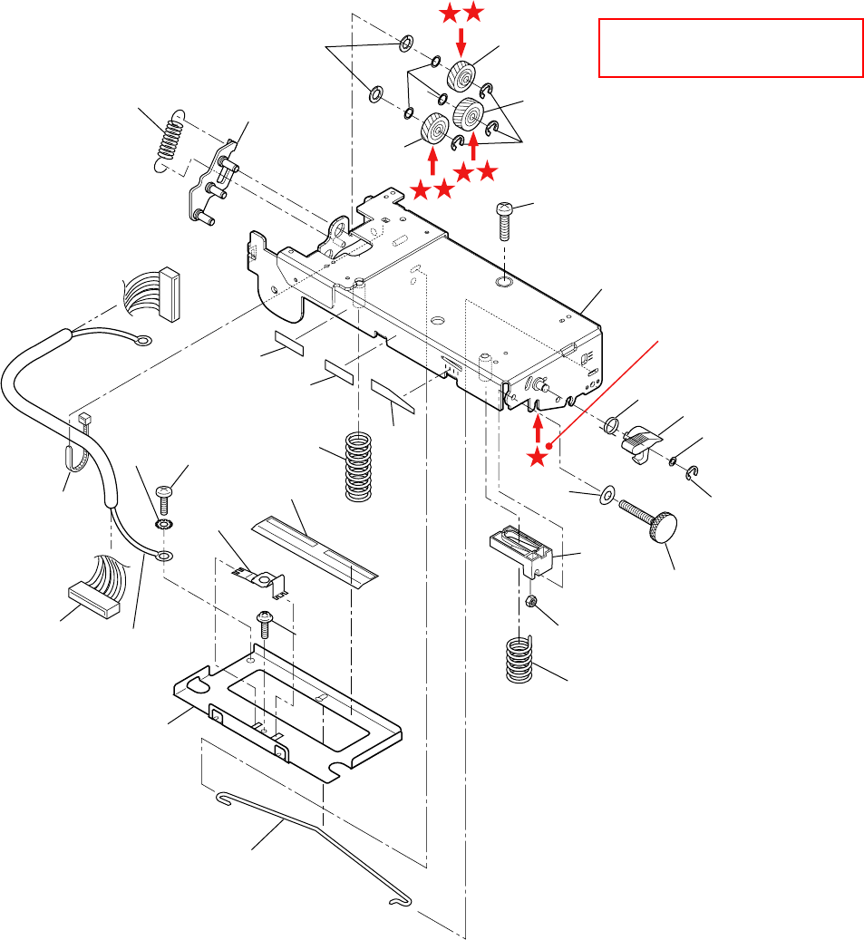
Chapter 5 Parts Lists
5-15 CL-S700/CL-S703
3-19
3-22 3-29
3-1
3-1
3-21
3-23
3-2
3-3 3-4
3-5
3-18
3-20
3-16
3-24
3-17
3-25
3-15
3-14
3-9
3-31-1
3-31-2
3-30
3-8
3-10
3-26
3-7
3-6
3-11
3-27
3-28
3-13
3-12
3-32
Apply lubricant to
other side also.
DRAWING NO. 3 Unit, Frame U (Rev. 1) For CL-S700/CL-S703
A
pply grease (Floil G-311S)
to the places marked with .

Chapter 5 Parts Lists
CL-S700/CL-S703 5-16
PARTS LIST for CL-S700/CL-S703 TITLE: Unit, Frame U Sheet No. 1/2
Drawing No. 3 Rev. No. 0
Location Part Name Part No. Q'ty/
Unit Remarks @
3-1 Idle Gear A Sub Assembly JE99683-0 2 23205720
3-2 Idle Gear B Sub Assembly JE99684-0 1 23205730
3-3 Gear Plate Spring JE99651-0 1 21903240
3-4 SA, Gear Plate JN29715-0 1
3-5 SA, Frame U JN44706-0 1
3-6 SA, Head Cable JN67707-0 1
3-7 Wire Tie C6701-101# 1
3-8 Spring, Head L JN13603-0 1
3-9 Head Balance Seal JE99434-0 1 25201200
3-10 Sheet, Cover Cable JN54908-0 1
3-11 Head Earth Plate JE99117-0 1 20803381
3-12 Head Plate JE99011-0 1 20803370
3-13 Offset Spring JE99016-0 1 21902562
3-14 Slider JE99048-0 1 25200861
3-15 Spring, Head R JN13602-0 1
3-16 Curved Washer JE99065-0 1 90500390
3-17 Adjust Screw JE99192-0 1 92100202
3-18 Open Lever Spring JE99019-0 1 21902601
3-19 Lever, Head Up JN14201-0 1
3-20 Polyslider Washer JE99064-0 1 90500380

Chapter 5 Parts Lists
5-17 CL-S700/CL-S703
PARTS LIST for CL-S700/CL-S703 TITLE: Unit, Frame U Sheet No. 2/2
Drawing No. 3 Rev. No. 1
Location Part Name Part No. Q'ty/
Unit Remarks @
3-21 Nyrock Screw JE99066-0 1 92100220
3-22 Polyslider 1 JN39902-0 2
3-23 E-Ring, 3.0 E60330-000F 3
3-24 E-Ring, 2.0 E60320-000F 1
3-25 Nut, M3 E40130-000F 1
3-26 Screw, BH (N), M4.0x4 E00540-040WF 1
3-27 Washer, EXT, T (N), 4 E50740-000WF 1
3-28 Screw, PH (TP), M3.0x8 E04230-080F 1
3-29 Polyslider JN39901-0 3
3-30 Label 2, Caution, Head AH90935-0 1 English
3-31-1 Label 7, Caution, Head AR99902-0 1 For CSA/French (Rev. No.1)
3-31-2 Label 6, Caution, Head AR99901-0 1 For CSE/German (Rev. No.1)
3-32 SA, Head Earth Cable JN67712-0 1

Chapter 5 Parts Lists
CL-S700/CL-S703 5-18
CL-S700/CL-S703
Drawing No. 4
Parts List & Location for SA, Front Tension Arm
Revision Up List
Sheet No. Rev. No. Date
1/1 0 Apr. 18, 2008
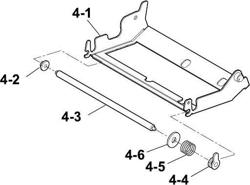
Chapter 5 Parts Lists
5-19 CL-S700/CL-S703
DRAWING NO. 4 SA, Front Tension Arm (Rev. 0) For CL-S700/CL-S703

Chapter 5 Parts Lists
CL-S700/CL-S703 5-20
PARTS LIST for CL-S700/CL-S703 TITLE: SA, Front Tension Arm Sheet No. 1/1
Drawing No. 4 Rev. No. 0
Location Part Name Part No. Q'ty/
Unit Remarks @
4-1 SA, Front Tension JN34701-0 1
4-2 Bushing JE99705-0 1 24400680
4-3 Shaft, Ribbon Guide FM JN32002-0 1
4-4 Bushing JE99704-0 1 24400670
4-5 Spring, Shaft Guide FM JN33601-0 1
4-6 Washer, Shaft Guide FM JN34107-0 1

Chapter 5 Parts Lists
5-21 CL-S700/CL-S703
CL-S700/CL-S703
Drawing No. 5
Parts List & Location for Unit, Frame Rear
Revision Up List
Sheet No. Rev. No. Date
1/1 0 Apr. 18, 2008
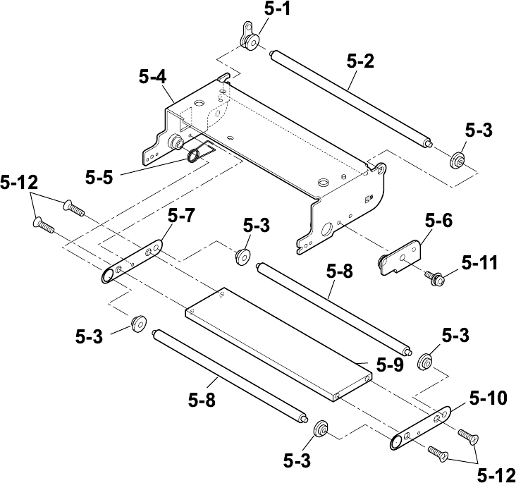
Chapter 5 Parts Lists
CL-S700/CL-S703 5-22
DRAWING NO. 5 Unit, Frame Rear (Rev. 0) For CL-S700/CL-S703

Chapter 5 Parts Lists
5-23 CL-S700/CL-S703
PARTS LIST for CL-S700/CL-S703 TITLE: Unit, Frame Rear Sheet No. 1/1
Drawing No. 5 Rev. No. 0
Location Part Name Part No. Q'ty/
Unit Remarks @
5-1 Bushing JE99704-0 1 24400670
5-2 Ribbon Guide Roller E JE99710-0 1 25100710
5-3 Bushing JE99705-0 5 24400680
5-4 SA, Frame Rear JN44705-0 1
5-5 Rear Arm Spring JE99650-0 1 21903231
5-6 SA, Plate Stopper Rear JN44708-0 1
5-7 Side Plate L JE99639-0 1 20804850
5-8 Ribbon Guide Roller C JE99709-0 2 25100690
5-9 Beam JE99667-0 1 23000680
5-10 Side Plate R JE99640-0 1 20804860
5-11 Screw, PH (SW+PW), M3.0x5 E04030-050F 1
5-12 Screw, FT, M3.0x6 E00230-060F 4

Chapter 5 Parts Lists
CL-S700/CL-S703 5-24
CL-S700/CL-S703
Drawing No. 6
Parts List & Location for SA, Frame Ribbon R
Revision Up List
Sheet No. Rev. No. Date
1/1 0 Apr. 18, 2008
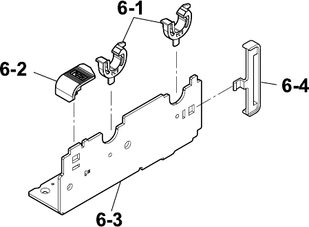
Chapter 5 Parts Lists
5-25 CL-S700/CL-S703
DRAWING NO. 6 SA, Frame Ribbon R (Rev. 0) For CL-S700/CL-S703

Chapter 5 Parts Lists
CL-S700/CL-S703 5-26
PARTS LIST for CL-S700/CL-S703 TITLE: SA, Frame Ribbon R Sheet No. 1/1
Drawing No. 6 Rev. No. 0
Location Part Name Part No. Q'ty/
Unit Remarks @
6-1 Holder, Ribbon Shaft JN34201-0 2
6-2 Knob, Ribbon Unit JN34202-0 1
6-3 Frame, Ribbon R JN34104-0 1
6-4 Plate, Ribbon Frame JN36202-0 1

Chapter 5 Parts Lists
5-27 CL-S700/CL-S703
CL-S700/CL-S703
Drawing No. 7
Parts List & Location for SA, Base Guide Open
Revision Up List
Sheet No. Rev. No. Date
1/1 0 Apr. 18, 2008
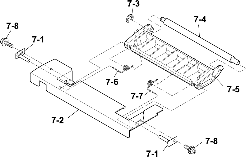
Chapter 5 Parts Lists
CL-S700/CL-S703 5-28
DRAWING NO. 7 SA, Base Guide Open (Rev. 0) For CL-S700/CL-S703

Chapter 5 Parts Lists
5-29 CL-S700/CL-S703
PARTS LIST for CL-S700/CL-S703 TITLE: SA, Base Guide Open Sheet No. 1/1
Drawing No. 7 Rev. No. 0
Location Part Name Part No. Q'ty/
Unit Remarks @
7-1 SA, Damper Shaft JN29703-0 2
7-2 Frame, Damper JN24105-0 1 Metal
7-3 E-Ring, 4.0 E60340-000F 1
7-4 Shaft, Damper JN22005-0 1
7-5 Frame, Damper JN24203-0 1 Plastic
7-6 Spring, Damper L JN23603-0 1
7-7 Spring, Damper R JN23602-0 1
7-8 Screw, PH (SW+PW), M3.0x5 E04030-050F 2

Chapter 5 Parts Lists
CL-S700/CL-S703 5-30
CL-S700/CL-S703
Drawing No. 8
Parts List & Location for Unit, Sensor Adjust
Revision Up List
Sheet No. Rev. No. Date
1/2 0 Apr. 18, 2008
2/2 0 Apr. 18, 2008
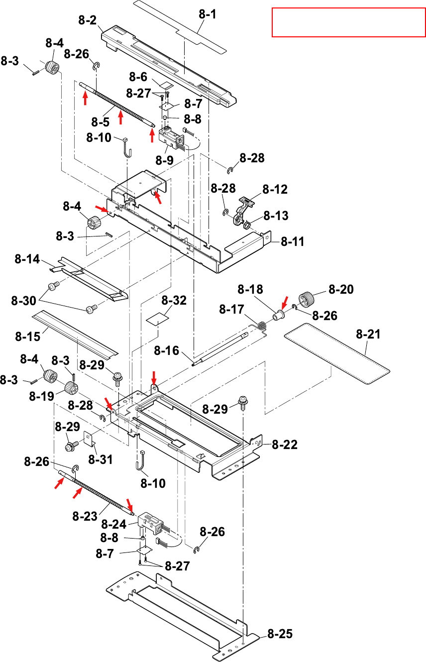
Chapter 5 Parts Lists
5-31 CL-S700/CL-S703
DRAWING NO. 8 Unit, Sensor Adjust (Rev. 0) For CL-S700/CL-S703
A
pply grease (Floil G-311S) to
the
p
laces marked with .

Chapter 5 Parts Lists
CL-S700/CL-S703 5-32
PARTS LIST for CL-S700/CL-S703 TITLE: Unit, Sensor Adjust Sheet No. 1/2
Drawing No. 8 Rev. No. 0
Location Part Name Part No. Q'ty/
Unit Remarks @
8-1 Open Guide Seal JE99179-0 1 71104522
8-2 Cover, Sensor Adjust JN24208-0 1
8-3 Pin, Teeth Spring, 1.2x8 E70412-080F 4
8-4 Screw Gear JE99279-0 3 24001020
8-5 Shaft, Screw Sensor U JN22004-0 1
8-6 Position Label JE99281-0 1 71104631
8-7 Stopper Plate JE99275-0 2 20803640
8-8 Move Pin JA99067-0 2 22601080
8-9 SA, Sensor U JN48704-0 1 Adjustable type
8-10 Wire Tie C6701-101# 2
8-11 SA, Open Guide U JN29702-0 1
8-12 Open Guide Lever JN24228-0 1
8-13 Open Guide Lever Spring JE99132-0 1 21902730
8-14 Paper Guide Plate JE99228-0 1 24600781
8-15 Sheet, Sensor Adjust JN54909-0 1
8-16 Shaft, Sensor Adjust JN22001-0 1
8-17 Spring, Guide Sensor Up JN23601-0 1
8-18 Bushing 3, Adjust Sensor JN22201-0 1
8-19 Ratchet Gear JE99280-0 1 24001030
8-20 Knob, Sensor Adjust JN24201-0 1

Chapter 5 Parts Lists
5-33 CL-S700/CL-S703
PARTS LIST for CL-S700/CL-S703 TITLE: Unit, Sensor Adjust Sheet No. 2/2
Drawing No. 8 Rev. No. 0
Location Part Name Part No. Q'ty/
Unit Remarks @
8-21 Cover, RFID JN24204-0 1
8-22 SA, Open Guide L JN29705-0 1
8-23 Shaft, Screw Sensor L JN22006-0 1
8-24 SA, Sensor Bottom JN48705-0 1 Adjustable type
8-25 Holder, Sensor L JN24101-0 1
8-26 E-Ring, 3.0 E60330-000F 4
8-27 Screw, No.0, FHT (BT#1), M2.0x4 E13220-040F 4
8-28 E-Ring, 2.0 E60320-000F 3
8-29 Screw, PH (SW+PW), M3.0x5 E04030-050F 5
8-30 Screw, PH, M3.0x3 E00130-030F 2
8-31 Ratchet Spring JE99276-0 1 21902760
8-32 Sheet, Sensor Adjust L JN24901-0 1

Chapter 5 Parts Lists
CL-S700/CL-S703 5-34
CL-S700/CL-S703
Drawing No. 9
Parts List & Location for Unit, Frame
Revision Up List
Sheet No. Rev. No. Date
1/3 1 Dec. 15, 2010
2/3 1 Dec. 15, 2010
2/3 1 Dec. 15, 2010
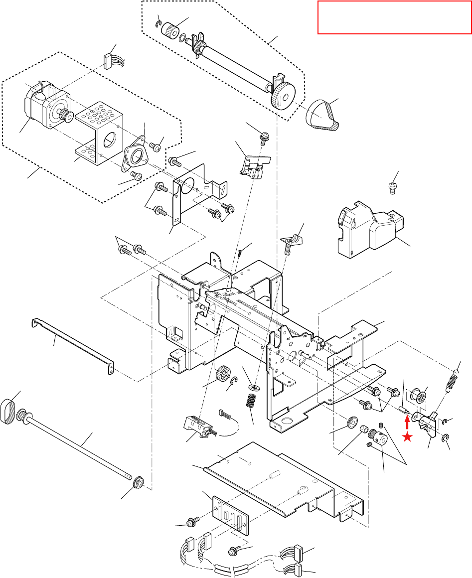
Chapter 5 Parts Lists
5-35 CL-S700/CL-S703
9-3
9-4
9-5
9-31
9-32
9-31
9-32
9-33 9-33 9-35
9-6
9-7
9-33
9-1
9-2
9-12
9-11
9-13
9-14
9-15 9-36
9-16
9-17
9-33
9-21
9-33
9-22
9-20
9-18
9-19
9-34
9-8
9-9
9-10
9-33
9-279-26
9-29
9-37
9-36
9-28
9-14
9-23
9-24 9-25
9-30
9-38-1
9-38-2
9-39
9-40
DRAWING NO. 9 Unit, Frame (Rev. 1) For CL-S700/CL-S703
A
pply grease (Floil G-311S) to
the place marked with .

Chapter 5 Parts Lists
CL-S700/CL-S703 5-36
PARTS LIST for CL-S700/CL-S703 TITLE: Unit, Frame Sheet No. 1/3
Drawing No. 9 Rev. No. 1
Location Part Name Part No. Q'ty/
Unit Remarks @
9-1 Unit, Roller Platen JN28801-1 1 (Rev. No.1)
9-2 Belt, Platen Drive JN26902-0 1
9-3 SA, Motor (with thermistor) ---- 1 Not supplied
9-4 Plate, Heat Sink Motor JN24109-0 1
9-5 Flange, Motor ---- 1 Not supplied
9-6 Bracket, Motor JN24108-0 1
9-7 SA, Sensor U JN48701-0 1 Fixed type
9-8 Paper Guide JE99045-0 1 24600660
9-9 Cover, Pulley JN24207-0 1
9-10 SA, Frame JN44701-0 1
9-11 Plate, Peel JN24107-0 1
9-12 Belt, Motor Drive JN26901-0 1
9-13 SA 1, Drive Shaft JN22702-0 1
9-14 Bearing, Drive Shaft JN21901-0 2
9-15 Idle Gear Sub Assembly JE99446-0 1 23204211
9-16 Friction Cork JE99037-0 1 24000910
9-17 Paper Guide Spring JE99017-0 1 21902571
9-18 SA, Sensor Bottom JN48702-0 1 Fixed type
9-19 SA, Frame Center JN44707-0 1
9-20 SA, Connect PCB JN66725-0 1 (Not used for CL-S700R)

Chapter 5 Parts Lists
5-37 CL-S700/CL-S703
PARTS LIST for CL-S700/CL-S703 TITLE: Unit, Frame Sheet No. 2/3
Drawing No. 9 Rev. No. 1
Location Part Name Part No. Q'ty/
Unit Remarks @
9-21 SA, Option Cable 1 JN67715-0 1
9-22 SA, Option Cable 2 JN67716-0 1
9-23 Bushing, Motor Drive JN22011-0 1
9-24 Pulley, Drive Shaft JN20302-0 1
9-25 Screw, HSS (KCP), M3.0x5 E30130-050F 2
9-26 Tension Pulley JE99154-0 1 2400090
9-27 Tensioner Pin JE99136-0 1 22601891
9-28 Plate, Tension JN24110-0 1
9-29 Tension Spring JE99131-0 1 21902722
9-30 SA, PF MTR Cable JN67705-0 1
9-31 Screw, PH, M3.0x6 E00130-060F 2
9-32 Screw, PH (SW+PW), M3.0x5 E04030-050F 3
9-33 Screw, PH (SW+PW), M3.0x6 E04030-060F 10
9-34 Screw, BH, M3.0x5K E00530-050KF 1
9-35 Screw, No.0, FHT (BT#1), M2.0x8 E13220-080F 1
9-36 E-Ring, 3.0 E60330-000F 2
9-37 E-Ring, 2.0 E60320-000F 1
9-38-1 Unit, Motor JN25801-0 1 For CL-S700/CL-S703 (Rev. No.1)
9-38-2 Unit, Motor JN25803-0 1 For CL-S700R (Rev. No.1)
9-39 Gear, One-way JN20201-0 1 (Rev. No.1)

Chapter 5 Parts Lists
CL-S700/CL-S703 5-38
PARTS LIST for CL-S700/CL-S703 TITLE: Unit, Frame Sheet No. 3/3
Drawing No. 9 Rev. No. 1
Location Part Name Part No. Q'ty/
Unit Remarks @
9-40 E-Ring, 4.0 E60340-000F 1 (Rev. No.1)

Chapter 5 Parts Lists
5-39 CL-S700/CL-S703
CL-S700/CL-S703
Drawing No. 10
Parts List & Location for Unit, Top Cover
Revision Up List
Sheet No. Rev. No. Date
1/1 0 Apr. 18, 2008
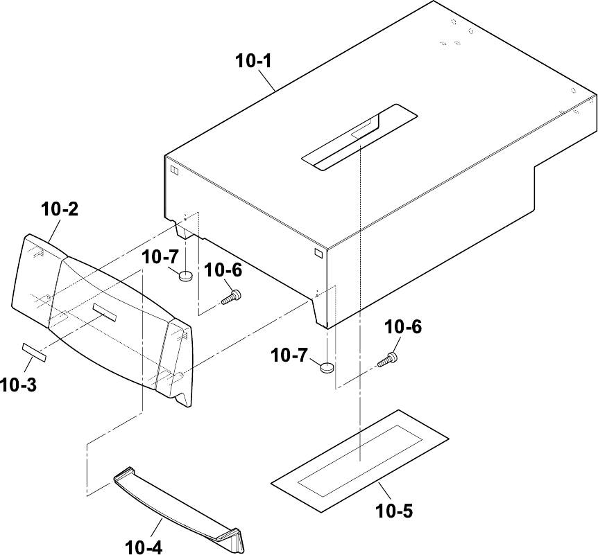
Chapter 5 Parts Lists
CL-S700/CL-S703 5-40
DRAWING NO. 10 Unit, Top Cover (Rev. 0) For CL-S700/CL-S703

Chapter 5 Parts Lists
5-41 CL-S700/CL-S703
PARTS LIST for CL-S700/CL-S703 TITLE: Unit, Top Cover Sheet No. 1/1
Drawing No. 10 Rev. No. 0
Location Part Name Part No. Q'ty/
Unit Remarks @
10-1 SA1, Top Cover JN56710-1 1
10-2 Cover, Front Top JN56207-0 1
10-3 Logo, CITIZEN JN54201-0 1
10-4 Cover, Cutter Blind JN56208-0 1
10-5 Cover, Window JN54101-0 1
10-6 Screw, PHT (#2), M3.0x6 E10130-060F 2
10-7 Spacer Leg, Case U JN56114-0 2

Chapter 5 Parts Lists
CL-S700/CL-S703 5-42
CL-S700/CL-S703
Drawing No. 11
Parts List & Location for SA, Ope-pane
Revision Up List
Sheet No. Rev. No. Date
1/1 1 Jan. 15, 2009
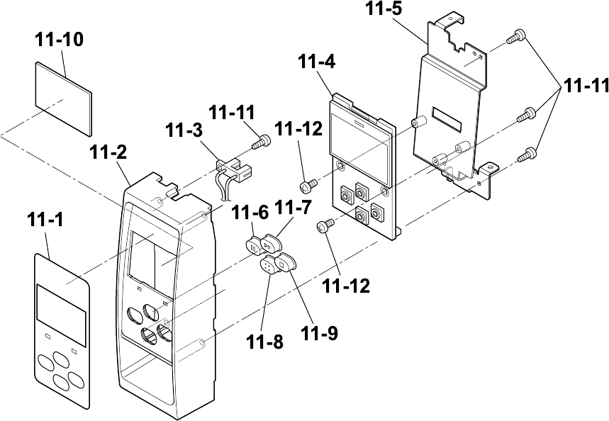
Chapter 5 Parts Lists
5-43 CL-S700/CL-S703
DRAWING NO. 11 SA, Ope-pane (Rev. 1) For CL-S700/CL-S703

Chapter 5 Parts Lists
CL-S700/CL-S703 5-44
PARTS LIST for CL-S700/CL-S703 TITLE: SA, Ope-pane Sheet No. 1/1
Drawing No. 11 Rev. No. 0
Location Part Name Part No. Q'ty/
Unit Remarks @
11-1 Sheet, Ope-Pane JN54901-0 1
11-2 Cover, Ope-Pane JN56202-0 1
11-3 SA, Cover Open Sens JN68705-0 1
11-4 SA, Ope-Pane PCB JN66704-0 1
11-5 SA, Ope-Pane Plate JN56706-0 1
11-6 Switch, Pause JN56212-0 1
11-7 Switch, Feed JN56211-0 1
11-8 Switch, Menu JN56210-0 1
11-9 Switch, Stop JN56213-0 1
11-10 Cover, LCD JN54102-0 1
11-11 Screw, PHT (#2), M3.0x6 E10130-060F 4
11-12 Screw, BH, M3.0x5 E00530-050F 2

Chapter 5 Parts Lists
5-45 CL-S700/CL-S703
CL-S700/CL-S703
Drawing No. 12
Parts List & Location for SA, Front Center
Revision Up List
Sheet No. Rev. No. Date
1/1 0 Apr. 18, 2008
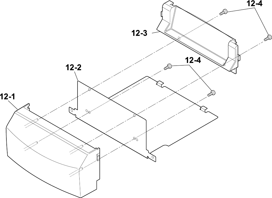
Chapter 5 Parts Lists
CL-S700/CL-S703 5-46
DRAWING NO. 12 SA, Front Center (Rev. 0) For CL-S700/CL-S703

Chapter 5 Parts Lists
5-47 CL-S700/CL-S703
PARTS LIST for CL-S700/CL-S703 TITLE: SA, Front Center Sheet No. 1/1
Drawing No. 12 Rev. No. 0
Location Part Name Part No. Q'ty/
Unit Remarks @
12-1 Cover, Front Center JN56204-0 1
12-2 Plate, Front Cover JN56121-0 1
12-3 Cover, Front JN56205-0 1
12-4 Screw, PHT (#2), M3.0x6 E10130-060F 4

Chapter 5 Parts Lists
CL-S700/CL-S703 5-48
CL-S700/CL-S703
Drawing No. 13
Parts List & Location for SA, Front Right
Revision Up List
Sheet No. Rev. No. Date
1/1 0 Apr. 18, 2008
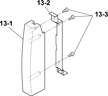
Chapter 5 Parts Lists
5-49 CL-S700/CL-S703
DRAWING NO. 13 SA, Front Right (Rev. 0) For CL-S700/CL-S703

Chapter 5 Parts Lists
CL-S700/CL-S703 5-50
PARTS LIST for CL-S700/CL-S703 TITLE: SA, Front Right Sheet No. 1/1
Drawing No. 13 Rev. No. 0
Location Part Name Part No. Q'ty/
Unit Remarks @
13-1 Cover, Front Right JN56203-0 1
13-2 Plate, Front Right JN56120-0 1
13-3 Screw, PHT (#2), M3.0x6 E10130-060F 3

Chapter 5 Parts Lists
5-51 CL-S700/CL-S703
CL-S700/CL-S703
Drawing No. 14
Parts List & Location for Unit, PCB
Revision Up List
Sheet No. Rev. No. Date
1/1 1 Dec. 15, 2010
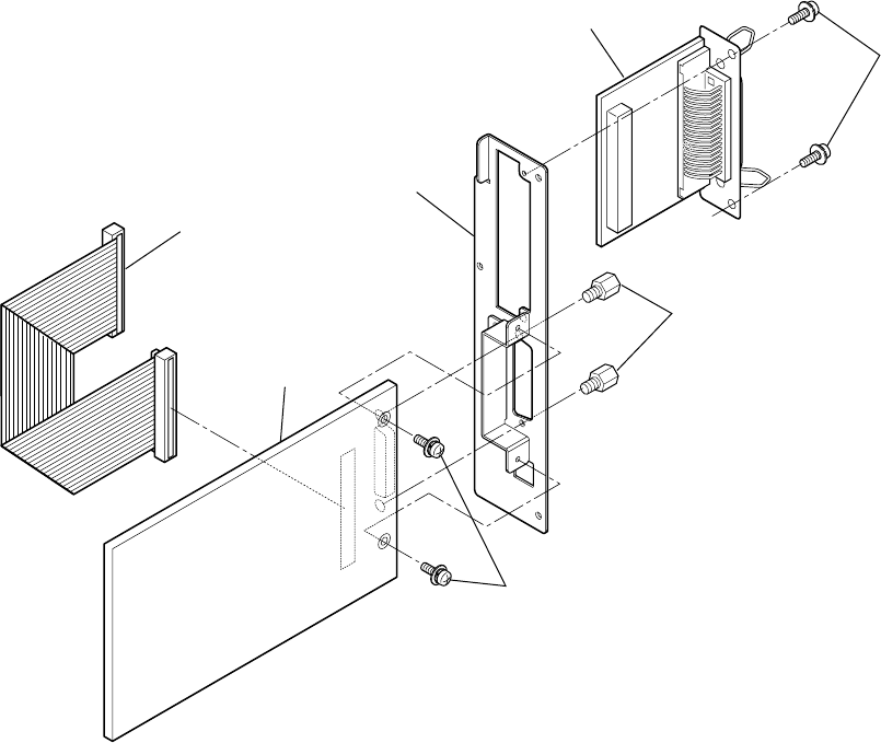
Chapter 5 Parts Lists
CL-S700/CL-S703 5-52
14-5
14-7
14-4
14-1
14-2-1
14-2-2
14-2-3
14-3
14-6
DRAWING NO. 14 Unit, PCB (Rev. 1) For CL-S700/CL-S703

Chapter 5 Parts Lists
5-53 CL-S700/CL-S703
PARTS LIST for CL-S700/CL-S703 TITLE: Unit, PCB Sheet No. 1/1
Drawing No. 14 Rev. No. 1
Location Part Name Part No. Q'ty/
Unit Remarks @
14-1 SA, Centro Cable JN67708-0 1
14-2-1 SA, Main PCB (200) JN66701-0 1 For CL-S700 (Rev. No.1)
14-2-2 SA, Main PCB (300) JN66702-0 1 For CL-S703 (Rev. No.1)
14-2-3 SA, Main PCB (200R) JN66718-0 1 For CL-S700R (Rev. No.1)
14-3 SA, Holder I/F JN56711-0 1
14-4 Unit, Centro PCB JM66825-1 1
14-5 Lock Screw (Inch) C6390-054# 2
14-6 Screw, PH (SW+PW), M3.0x5 E04030-050F 2
14-7 Screw, BH, M3.0x5 E00530-050F 2

Chapter 5 Parts Lists
CL-S700/CL-S703 5-54
CL-S700/CL-S703
Drawing No. -
Parts List & Location for Accessories
Revision Up List
Sheet No. Rev. No. Date
1/1 0 Apr. 18, 2008

Chapter 5 Parts Lists
5-55 CL-S700/CL-S703
PARTS LIST for CL-S700/CL-S703 TITLE: Accessories Sheet No. 1/1
Drawing No. - Rev. No. 0
Location Part Name Part No. Q'ty/
Unit Remarks @
- Cord Set (Ul/CSA) C6009-000# 1 For CSA
- Cord Set (OE Straight) C6009-200# 1 For CSE
- Cord Set (UK) C6009-300# 1 For CSE
- CD-ROM, User's Manual JN749** 1 to be revised without notice
- Guide, Quick Start JN749** 1 to be revised without notice
- Head, Cleaner JM79904-0 1
- Label, Accessory RPR JN79901-0 1
- Thermal, Roll Paper JM79907-0 1 For CSA
- Ribbon (B110A) 35*114 JM39901-0 1
- Ribbon Core 25*114 JM39902-0 1
Chapter 5 Parts Lists
5-55
CL-S700R
Chapter 5 Parts Lists
for CL-S700R
Table of Contents
Recommended Spare Parts List .............................................................................................. 5-56
Drawing No. 1 Parts List & Location for General Assembly ............................................... 5-58
Drawing No. 2 Parts List & Location for Unit, Rewinder..................................................... 5-63
Drawing No. 3 Parts List & Location for SA1, Peeler ......................................................... 5-69
Drawing No. 4 Parts List & Location for SA2, Peeler ......................................................... 5-72

Chapter 5 Parts Lists
CL-S700R 5-56
CL-S700R
Recommended Spare Parts List
Revision Up List
Sheet No. Rev. No. Date
1/1 0 Apr. 18, 2008
Chapter 5 Parts Lists
5-57 CL-S700R
PARTS LIST for CL-S700R TITLE: Recommended Spare Parts List Sheet No. 1/1
Rev. No. 0
Maint. Class
Item
No. Location Part No. Part Name Q'ty/
Unit Worn Casual Remarks Dedicated for
CL-S700R
1 1-15 JN66801-0 Unit, Power Supply 1 |
2 2-13 JN09802-0 Unit, Head 1 |
3 8-9 JN48704-0 SA, Sensor U 1 | Adjustable type
4 8-24 JN48705-0 SA, Sensor Bottom 1 | Adjustable type
5 9-1 JN28801-0 Unit, Roller Platen 1 |
6 9-39 JN25803-0 Unit, Motor 1 | |
7 9-7 JN48701-0 SA, Sensor U 1 | Fixed type
8 9-18 JN48702-0 SA, Sensor Bottom 1 | Fixed type
9 14-2 JN66718-0 SA, Main PCB (200R) 1 | |
10
11
12
13
14
15
16
17
18
19
20

Chapter 5 Parts Lists
CL-S700R 5-58
CL-S700R
Drawing No. 1
Parts List & Location for General Assembly
Revision Up List
Sheet No. Rev. No. Date
1/3 0 Apr. 18, 2008
2/3 0 Apr. 18, 2008
3/3 0 Apr. 18, 2008
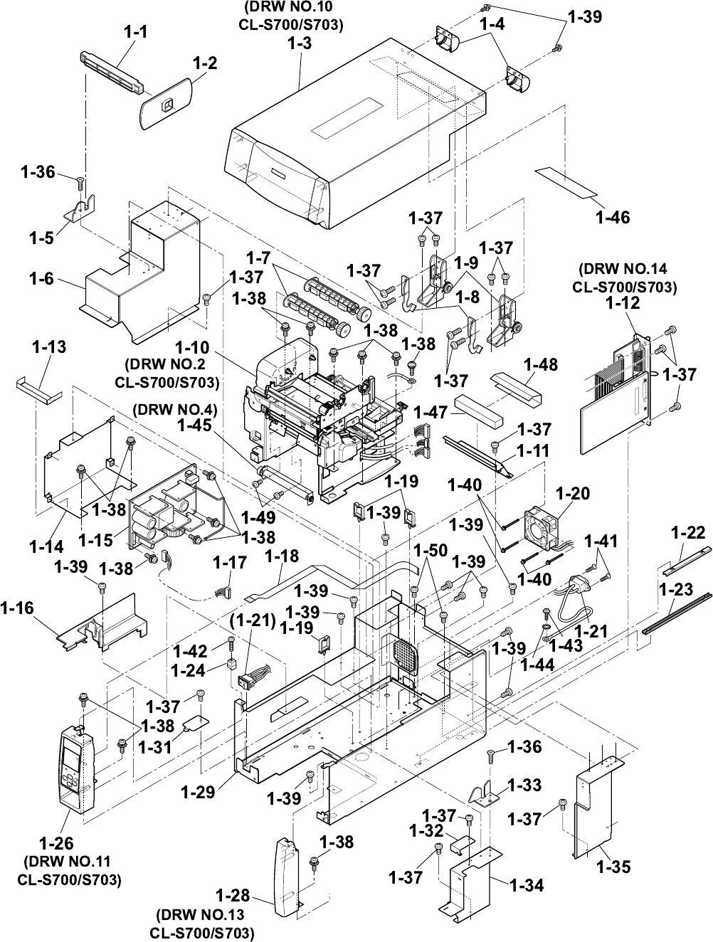
Chapter 5 Parts Lists
5-59 CL-S700R
DRAWING NO. 1 General Assembly (Rev. 0) for CL-S700R

Chapter 5 Parts Lists
CL-S700R 5-60
PARTS LIST for CL-S700R TITLE: General Assembly Sheet No. 1/3
Drawing No. 1 Rev. No. 0
Location Part Name Part No. Q'ty/
Unit Remarks Dedicated for
CL-S700R
1-1 Roll Holder JE99090-0 1 24600730
1-2 Flange, Paper Wide JM79201-0 1
1-3 Unit, Top Cover ---- 1 Ref: Drawing No. 10 / CL-S700, S703
1-4 Cover, Hinge JN56209-0 2
1-5 Holder, Paper Shaft Left JN56116-0 1
1-6 SA, Cover Inner Power JN56704-0 1
1-7 SA, Ribbon Holder JM34710-1 2
1-8 Stopper, Hinge JN54103-0 2
1-9 SA, Hinge JN59905-0 2
1-10 Unit, Mechanism JN99801-0 1 Ref: Drawing No. 2 / CL-S700, S703
1-11 Cover, Inner Paper JN56112-0 1
1-12 Unit, PCB - 1 Ref.: Drawing No. 14 / CL-S700, S703
1-13 Sheet 1, Power Protect JN54910-0 1
1-14 Plate, Power JN64101-0 1
1-15 Unit, Power Supply JN66801-0 1
1-16 Cover, Cable JN56201-0 1
1-17 SA, Power Cable JN67706-0 1
1-18 Cable, Ope-pane FFC JN67901-0 1
1-19 WS-2NS (Cable, Clamp) JN59903-0 3
1-20 SA, Fan JN65901-0 1

Chapter 5 Parts Lists
5-61 CL-S700R
PARTS LIST for CL-S700R TITLE: General Assembly Sheet No. 2/3
Drawing No. 1 Rev. No. 0
Location Part Name Part No. Q'ty/
Unit Remarks Dedicated for
CL-S700R
1-21 SA, Power SW Cable JN67709-0 1 Including Inlet
1-22 Rail, Guide U JN54906-0 1
1-23 Rail, Guide Base JN54907-0 1
1-24 Guide, Top Cover JN54202-0 1
1-25 - - -
1-26 SA, Ope-pane JN56705-0 1 Ref.: Drawing No. 11 / CL-S700, S703
1-27 - - -
1-28 SA, Front Right JN56707-0 1 Ref.: Drawing No. 13 / CL-S700, S703
1-29 SA, Case L JN56701-1 1
1-30 - - -
1-31 Plate, Cable Cover JN56113-0 1
1-32 Cover, Sensor Adjust JN56115-0 1
1-33 Holder, Paper Shaft Right JN56117-0 1
1-34 Cover, Inner PCB Front JN56110-0 1
1-35 SA, Cover Inner PCB Rear JN56713-0 1
1-36 Screw, FH, M3.0x6 E00230-060F 2
1-37 Screw, BH, M3.0x5 E00530-050F 19
1-38 Screw, PH (SW+PW), M3.0x5 E04030-050F 15
1-39 Screw, BH, M3.0x5K E00530-050KF 11
1-40 Screw, PH (SW+PW), M4.0x30 E00940-300F 4

Chapter 5 Parts Lists
CL-S700R 5-62
PARTS LIST for CL-S700R TITLE: General Assembly Sheet No. 3/3
Drawing No. 1 Rev. No. 0
Location Part Name Part No. Q'ty/
Unit Remarks Dedicated for
CL-S700R
1-41 Screw, FH, M3.0x6 E00230-060F 2
1-42 Screw, PH, M3.0x12 E00130-120F 1
1-43 Screw, BH (N), M4.0x4 E00540-040WF 1
1-44 Washer, EXT, T (N), 4 E50740-000WF 1
1-45 SA2, Peeler JN29713-0 1 Ref.: Drawing No. 4 |
1-46 Label, Peel Guidance JN99907-0 1 |
1-47 Cushion, Damper JN24143-0 1 |
1-48 Sheet, Damper JN24142-0 1 |
1-49 Screw, PH (SW+PW), M3.0x5 E04030-050F 2 |
1-50 Screw, BH, M3.0x5 E00530-050F 2 |

Chapter 5 Parts Lists
5-63 CL-S700R
CL-S700R
Drawing No. 2
Parts List & Location for Unit, Rewinder
Revision Up List
Sheet No. Rev. No. Date
1/4 0 Apr. 18, 2008
2/4 0 Apr. 18, 2008
3/4 0 Apr. 18, 2008
4/4 0 Apr. 18, 2008
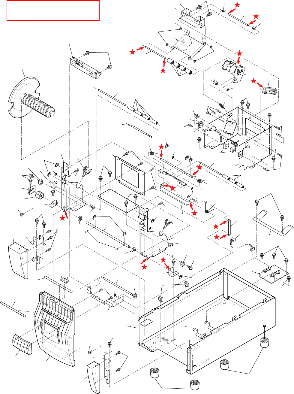
Chapter 5 Parts Lists
CL-S700R 5-64
DRAWING NO. 2 Unit, Rewinder (Rev. 0) for CL-S700R
Apply grease (Floil G-311S) to
the places marked with .
2-56
2-56
2-67
2-58
2-64
2-64
2-59
2-64
2-55
2-63
2-63
2-54
2-50
2-49
2-48
2-45 2-46
2-64
2-38
2-36
2-63
2-37
2-64
2-35 2-34
2-64
2-66
2-33
2-19
2-20
2-64
2-21
2-22
2-61 2-5
2-62 2-2
2-4
2-1
2-3
2-61
2-7 2-9 2-10
2-64
2-61
2-11
2-63
2-15
2-64
2-63
2-64
2-14
2-63
2-18
2-17
2-6
2-22
2-66
2-25
2-61
2-28
2-63
2-63
2-63
2-27
2-29
2-59
2-26
2-61
2-66
2-23
2-63 2-64
2-32
2-64
2-30
2-31
2-64
2-66
2-61 2-42
2-43
2-66
2-64 2-35
2-64
2-66
2-63
2-39 2-40
2-41
2-51
2-66
2-63
2-61
2-52
2-44
2-57 2-66
2-39
2-61
2-24
2-6
2-16
2-47
2-53
2-63
2-64
2-12
2-13
2-8
2-65
(DRW NO.3)

Chapter 5 Parts Lists
5-65 CL-S700R
PARTS LIST for CL-S700R TITLE: Unit, Rewinder Sheet No. 1/4
Drawing No. 2 Rev. No. 0
Location Part Name Part No. Q'ty/
Unit Remarks @
2-1 Shaft, Measure Sensor JN22018-0 1
2-2 Spring, Measure Sensor L JN23609-0 1
2-3 Spring, Measure Sensor R JN23610-0 1
2-4 Plate, Measure Sensor JN24120-0 1
2-5 Plate, Measure Flap JN24121-0 1
2-6 Shaft, Damper JN22012-0 2
2-7 Roller, Measure Sensor JN24225-0 4
2-8 SA, Rewinder Motor JN29710-0 1
2-9 Pivot, Rewinder Motor Plate JN22017-0 1
2-10 Guide, Motor Plate JN24223-0 1
2-11 Spring, Rewinder Motor JN23608-0 1
2-12 Sheet, Damper Plate Cover JN24145-0 1
2-13 Sheet, Peel Sensor Cover JN24144-0 1
2-14 Guide, Rewinder Flange JN24226-0 2
2-15 SA, Interlock SW JN68710-0 1
2-16 Plate, Nut JN24138-0 1
2-17 Stopper, Rewinder Door JN24227-0 2
2-18 Frame, Rewinder Inner JN44110-0 1
2-19 SA, Rewinder Flange JN29708-0 1
2-20 SA1, Peeler JN29706-0 1

Chapter 5 Parts Lists
CL-S700R 5-66
PARTS LIST for CL-S700R TITLE: Unit, Rewinder Sheet No. 2/4
Drawing No. 2 Rev. No. 0
Location Part Name Part No. Q'ty/
Unit Remarks @
2-21 Shaft, Guide Roller JN22015-0 1
2-22 Roller, Damper JN24216-0 7
2-23 Spring, Damper Rewinder L JN23604-0 1
2-24 Shaft, Handle Plate JN22014-0 1
2-25 Spring, Damper Rewinder R JN23605-0 1
2-26 Plate, Damper JN24114-0 1
2-27 Spring, Handle R JN23606-0 1
2-28 Plate, Handle JN24115-0 1
2-29 SA, Handle Link JN56716-0 1
2-30 Frame2, Door Center JN56135-0 1
2-31 Frame1, Door Center JN56134-0 1
2-32 Holder, Rewinder Shaft L JN24210-0 1
2-33 Frame, Door L JN56132-0 1
2-34 Plate, Rewinder SW JN24213-0 1
2-35 Stopper Rewinder JN24211-0 2
2-36 Plate, Torque Limiter JN24124-0 1
2-37 Torque Limiter JN29903-0 1
2-38 Holder, Door Shaft L JN24126-0 1
2-39 Ring, Damper JN24212-0 2
2-40 Shaft, Door JN22020-0 1

Chapter 5 Parts Lists
5-67 CL-S700R
PARTS LIST for CL-S700R TITLE: Unit, Rewinder Sheet No. 3/4
Drawing No. 2 Rev. No. 0
Location Part Name Part No. Q'ty/
Unit Remarks @
2-41 Pin, Parallel(A), M2.0×12 E70120-120F 2
2-42 Holder, Rewinder Shaft R JN24209-0 1
2-43 Frame, Door R JN56133-0 1
2-44 Holder, Door Shaft R JN24127-0 1
2-45 Case, Rewinder Front L JN56215-0 1
2-46 SA1, Front Case Rewinder L JN56723-0 1
2-47 Sheet, Anti-Adhere JN54107-0 1
2-48 Cover Rewinder JN24215-0 1
2-49 Handle JN24217-0 1
2-50 Door, Rewinder JN56214-0 1
2-51 Shaft, Handle JN22016-0 1
2-52 Plate, Handle Bracket JN24116-0 1
2-53 SA1, Front Case Rewinder R JN56725-0 1
2-54 Case, Rewinder Front R JN56216-0 1
2-55 SA1, Rewinder Case JN56718-0 1
2-56 Leg, Case JN56901-0 4
2-57 CKS-16-L (Cable, Clamp) JN59904-0 2
2-58 Plate, Spring Rewinder JN24125-0 1
2-59 SA, Rewinder PCB JN66705-0 1
2-60 SA, RW Cable JN67721-0 1

Chapter 5 Parts Lists
CL-S700R 5-68
PARTS LIST for CL-S700R TITLE: Unit, Rewinder Sheet No. 4/4
Drawing No. 2 Rev. No. 0
Location Part Name Part No. Q'ty/
Unit Remarks @
2-61 E-Ring, 3.0 E60330-000F 11
2-62 Screw, PH (SW+PW), M3.0×6 E04030-060F 2
2-63 Screw, PHT (#2), M3.0x6 E10130-060F 22
2-64 Screw, PH (SW+PW), M3.0×5 E04030-050F 24
2-65 Screw, PH (PW), M2×10 E00620-100F 2
2-66 E-Ring, 4.0 E60340-000F 11
2-67 Screw, PH (SW+PW), M3.0×4 E04030-040F 2

Chapter 5 Parts Lists
5-69 CL-S700R
CL-S700R
Drawing No. 3
Parts List & Location for SA1, Peeler
Revision Up List
Sheet No. Rev. No. Date
1/1 0 Apr. 18, 2008
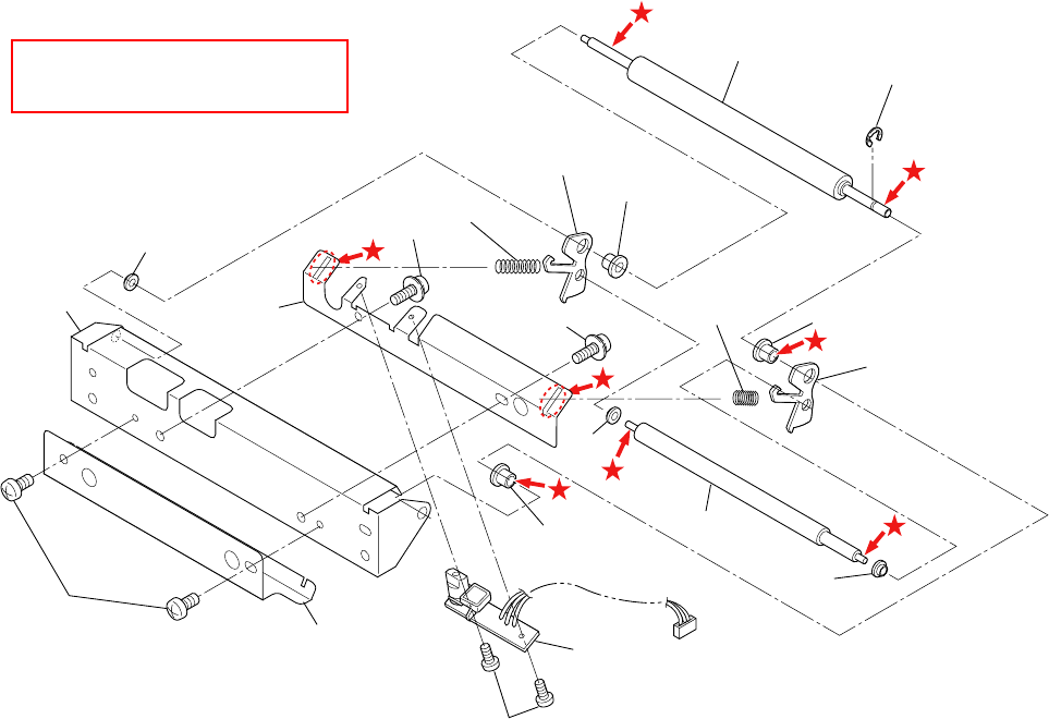
Chapter 5 Parts Lists
CL-S700R 5-70
DRAWING NO. 3 SA1, Peeler (Rev. 0) for CL-S700R
Apply grease (Floil G-311S) to
the places marked with .
3-1 3-12
3-2
3-5
3-3
3-4
3-13
3-13
3-8
3-7
3-9
3-10
3-14
3-15
3-11
3-6
3-7
3-7
3-2
3-2
3-3

Chapter 5 Parts Lists
5-71 CL-S700R
PARTS LIST for CL-S700R TITLE: SA1, Peeler Sheet No. 1/1
Drawing No. 3 Rev. No. 0
Location Part Name Part No. Q'ty/
Unit Remarks @
3-1 Roller, Idle Rewinder JN28502-0 1
3-2 Bush, Idle JE99750-0 3
3-3 Plate, Friction Link JE99325-0 2
3-4 Spring, L Friction JE99761-0 1
3-5 Spring, R Friction JE99760-0 1
3-6 Roller, Friction JE99758-0 1
3-7 Bush, Friction JE99762-0 3
3-8 Plate, Sensor Holder JN24112-0 1
3-9 Plate1, Peeler JN24111-0 1
3-10 Plate, Friction Peeler JN24113-0 1
3-11 SA, Peel Sensor JE69149-2 1
3-12 E-Ring, 2.0 E60320-000F 1
3-13 Screw, PH(SW+PW), M3.0x5 E04030-050F 2
3-14 Screw,PH,M2.0x3 E00120-030WF 2
3-15 Screw, BH, M3.0x5 E00530-050F 2

Chapter 5 Parts Lists
CL-S700R 5-72
CL-S700R
Drawing No. 4
Parts List & Location for SA2, Peeler
Revision Up List
Sheet No. Rev. No. Date
1/1 0 Apr. 18, 2008
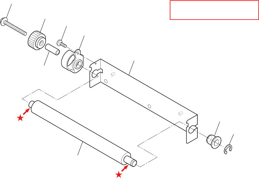
Chapter 5 Parts Lists
5-73 CL-S700R
DRAWING NO. 4 SA2, Peeler (Rev. 0) for CL-S700R
A
pply grease (Floil G-311S) to
the places marked with .
4-2
4-7
4-5
4-6
4-3
4-4
4-8
4-9
4-1

Chapter 5 Parts Lists
CL-S700R 5-74
PARTS LIST for CL-S700R TITLE: SA2, Peeler Sheet No. 1/1
Drawing No. 4 Rev. No. 0
Location Part Name Part No. Q'ty/
Unit Remarks @
4-1 Roll, Peel JE99338-1 1
4-2 Plate2, Peeler JN24123-0 1
4-3 Bushing, Peel Roller JE99370-0 1
4-4 Shaft, Oneway Clutch JE99366-0 1
4-5 SA1, Peel Gear JE99335-1 1
4-6 Screw, TH, M2.0×4 (NI) E00420-040WF 1
4-7 Screw, PH (SW+PW#2), M2.6×14 E00926-140F 1
4-8 Bushing2, Peel Roller JE99341-0 1
4-9 E-Ring, 4.0 E60340-000F 1

Chapter 6 Circuit Diagrams
CL-S700/CL-S703/CL-S700R
CHAPTER 6
CIRCUIT DIAGRAMS
Chapter 6 Circuit Diagrams
CL-S700/CL-S703/CL-S700R 6-2
Chapter 6 Circuit Diagrams
Table of Contents
Inter Connection (Main PCB 1/15) (CL-S700/CL-S703) .......................................................... 6-3
Inter Connection (Main PCB 1/15) (CL-S700R)....................................................................... 6-4
Circuit Diagram (Main PCB 2/15) [CPU (1)]............................................................................. 6-5
Circuit Diagram (Main PCB 3/15) [CPU (2)/DAC] .................................................................... 6-6
Circuit Diagram (Main PCB 4/15) [ROM] ................................................................................. 6-7
Circuit Diagram (Main PCB 5/15) [RAM].................................................................................. 6-8
Circuit Diagram (Main PCB 6/15) [Custom IC]......................................................................... 6-9
Circuit Diagram (Main PCB 7/15) [Head Control] ....................................................................6-10
Circuit Diagram (Main PCB 8/15) [PF Motor Control] .............................................................. 6-11
Circuit Diagram (Main PCB 9/15) [Sensor] .............................................................................. 6-12
Circuit Diagram (Main PCB 10/15) [Power/Buzzer/Fan] .......................................................... 6-13
Circuit Diagram (Main PCB 11/15) [RFID/Ope-Pane] .............................................................. 6-14
Circuit Diagram (Main PCB 12/15) [Cutter/Rewinder]..............................................................6-15
Circuit Diagram (Main PCB 13/15) [Centronics I/F] ................................................................. 6-16
Circuit Diagram (Main PCB 14/15) [Serial I/F] ......................................................................... 6-17
Circuit Diagram (Main PCB 15/15) [USB I/F] ........................................................................... 6-18
Circuit Diagram (Power Supply PCB (100/240V)) ................................................................... 6-19
Circuit Diagram (Ope-pane PCB).............................................................................................6-20
Circuit Diagram (Centronics PCB) ........................................................................................... 6-21
Circuit Diagram (Connect PCB) (CL-S700/CL-S703) .............................................................. 6-22
Circuit Diagram (Rewinder PCB) (CL-S700R) ......................................................................... 6-23
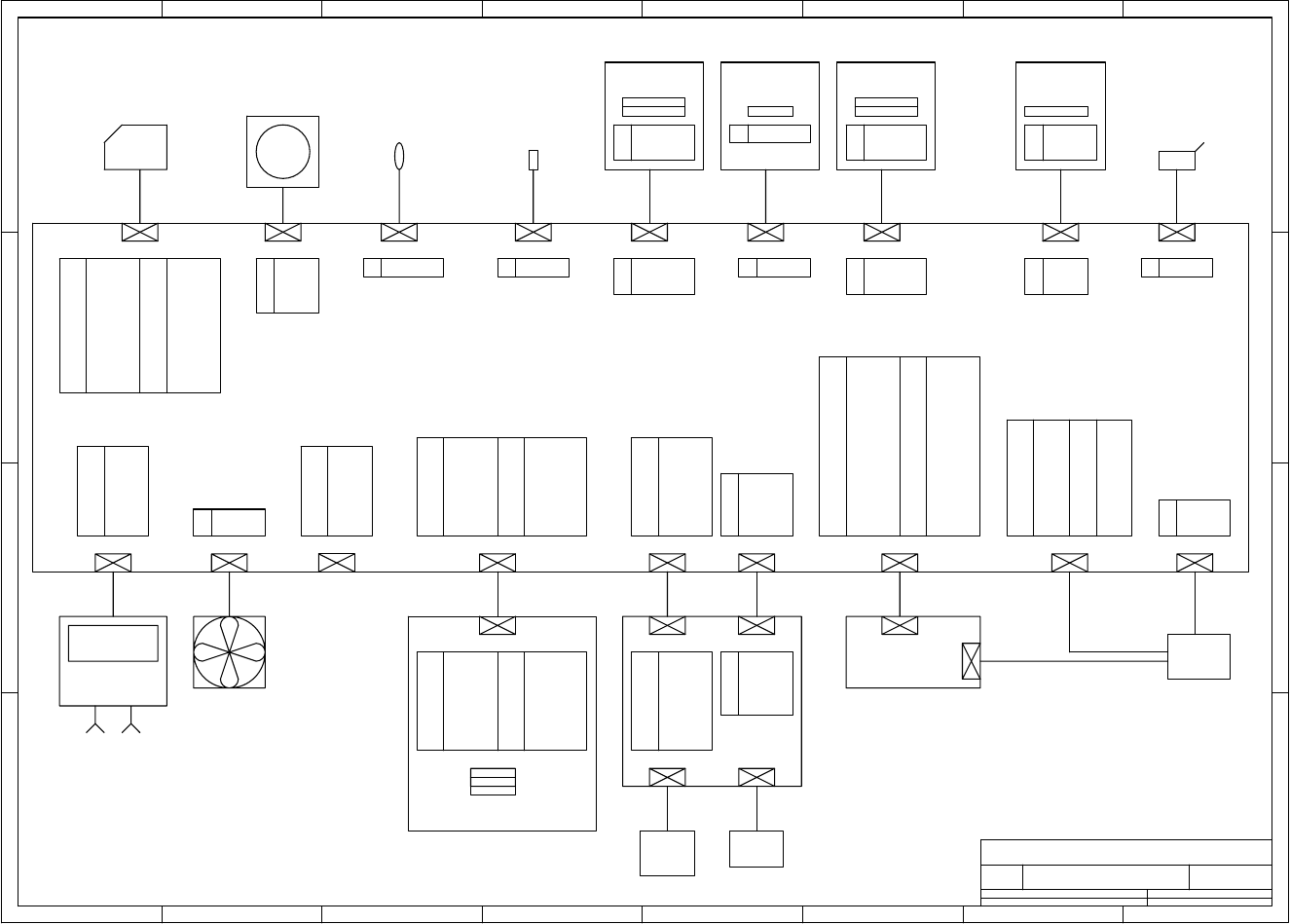
Chapter 6 Circuit Diagrams
6-3 CL-S700/CL-S703/CL-S700R
1 2 3 4 5 678
A
B
C
D
8
76
54321
D
C
B
A
Title
Number RevisionSize
A4
Date: Sheet of
File: Drawn By:
A
Inter Connection (CL-S700/CL-S703) (1/15)
JN66701-0/JN66702-0
AC/DC
CONVERTER
UNIT,POWER
SUPPLY
JN66801-**F
J19
J3 J21
J16
J8
J18
AC INPUT
J15
J4
SA,MAIN PCB (200)
JN66701-**F
P.GND
15
HEADD1
20
26
21
S.GND
P.GND
2
+24V
P.GND
1
P.GND
16
+3.3V4
+24V+5V
P.GND
+24V
HEADD3
23
HEADSTB
17
19
24
7
14
13
HEADLAT
HEADD4
5
6
318
HEADCLK
9
P.GND
11
+24V
P.GND
+24V
P.GND
P.GND
HDTMP
10
12
+24V
+24V
22
25
8
UNIT, HEAD
SA, HEAD CABLE
UNIT, MOTOR
JN25801-**F
MOTOR
2
ACOM
A
6
5
BCOM
3
4
-A
-B
B
1
SA, FRONT SENS
CABLE L
JN67714-**F
1 DOWN LED A
DOWN TR C
DOWN LED K2
3
SA, RIB ENC
CABLE
JN66704-**F
PHOTO INT
SA, RIB SENS PCB
JN66722-**F
TR C3
LED A
1
2 LED K
J12
2
3
7
6
P.GND5
4
+24V
P.GND
+24V
+24V8
P.GND
P.GND
1 +5V
4
5
P.GND
6
S.GND
HPSENS1
P.GND
1
HPSENS0
DCMTR1
+24V
3
+24V
9
8
DCMTR0
7
2
SA,OPTION
CABLE 1
JN67715-**F
J801
SA,OPTION
CABLE 2
JN67716-**F
J803
SA,CONNECT PCB
JN66725-**F
FAN -
3
1
2
FANLOCK
FAN +
J14
LED x8
SA,OPEPANE PCB
JN66704-**F
J401
CABLE,OPEPANE FFC
JN67901-**F
SW x4
N.C.
5
S.GND
6
3
1
RXD1
2
RFRUN9
TXD1
8
7
4
+5V
N.C.
S.GND
S.GND
J13
RF-ID(OPTION)
J17
S.GND
S.GND
xRESET
2
N.C.
31
DATA 1
DATA 3
xFAULT
26
+5V
PE
1
N.C.
11
39
DATA 0
xSTROBE
DATA 2
14
xPRIME
IETYP1
13
S.GND
DATA 6
N.C.
N.C.
32
S.GND
SLCT
33
BUSY
S.GND
S.GND
4
5
21
20
28
DATA 4
34
3
xATFD-XT
6
15
29
7
12
38
DATA 5
24S.GND
22
25
S.GND
23
DATA 7
36 xSLCT-IN
30
S.GND
16
S.GND
37
27
S.GND
IETYP0
S.GND
8
35
18
S.GND
xACKNLG
+5V
19
10
9
17
40 4
2
1
USBLGND
DM
USBVCC
3DP
21
RTS
N.C.
N.C.
11
F.GND
N.C.
15
20
13
RXD
N.C.
N.C.
DSR
25
N.C.
5
N.C.
2
7
+5V
N.C.
N.C.
10
12 N.C.
CTS
19
N.C.
1
3
SGND
6
23
9
N.C.
N.C.
N.C.
TXD
16
N.C.
14
8
4
18
22
DTR
17
N.C.24
COMPUTER
HOST
USB1.1RS232CSA,CENTRO
CABLE
JN67708-**F
SA,CENTRONICS I/F
CON PCB JM66710-**F
CN101
CN102
IEEE1284
N.C.
SA, LOWER SENS PCB
JN66721-**F
IED
SA, FRONT SENS L
JN68708-**F
SA,POWER
CABLE
JN67706-**F
27
28
29
30
HEADD2
HEADSTB
+24V
+24V
SA, PF MTR CABLE
JN67705-**F
1 VREF(+3V)
MOTTMP2
J5
SA, PF MTR THM
JN68706-**F
1 UP LED A
UP LED K2
J6
SA, FRONT SENS U
JN68702-**F
SA, FRONT SENS
CABLE U
JN67702-**F
4 DOWN TR E
4 DOWN TR E
1 DOWN LED A
DOWN TR C
DOWN LED K2
3
PHOTO TR
SA, LOWER SENS PCB
JN66721-**F
IED
SA, ADJ SENS L
JN68707-**F
1 UP LED A
UP LED K2
J7
SA, ADJ SENS
CABLE U
JN67701-**F
4 DOWN TR E
4 DOWN TR E
1 DOWN LED A
DOWN TR C
DOWN LED K2
3
PHOTO TR
SA, ADJ SENS
CABLE L
JN67713-**F
1 DOWN LED A
DOWN TR C
DOWN LED K2
3
J22
SA, UPPER SENS PCB
JN66720-**F
SA, ADJ SENS U
JN68701-**F
IED
1
UP LED K
UP LED A
2
4 TR E
4 TR E
TR C3
LED A
1
2 LED K
SA, RIB ENC SENS
JN68703-**F
SA, HEAD UP SW
JN68704-**F
SA, HEAD UP
CABLE
JN66703-**F
HDUSENS1
S.GND2
J9
9
10 +24V
S.GND
SA,FAN
JN65901-**F
10 RFOSC
LCD_CD
15
N.C.
20
21
LCD_LED2
N.C.
2
CS_LCD
1
DACCLK
16
SW14
CV_OPN
S.GND
LCD_LED4
17
19
7
14
13
N.C.
LCD_LED3
5
6
3
18
LCD_LED1
9
S.GND
11
+5V
DACIN
N.C.
SW3
SW4
SW2
10
12
+3.3V
S.GND22
8
LCD_CD
15
N.C.
20
21
LCD_LED2
N.C.
2
CS_LCD
1
DACCLK
16
SW14
CV_OPN
S.GND
LCD_LED4
17
19
7
14
13
N.C.
LCD_LED3
5
6
3
18
LCD_LED1
9
S.GND
11
+5V
DACIN
N.C.
SW3
SW4
SW2
10
12
+3.3V
S.GND22
8
LCD
10
11
MTTH
CPRTYP0
4
5
MTENC
6
OPN
MTREF
1
CPRTYP1
S.GND
3
+5V
PEELSENS
7
2
4
5
P.GND
6
S.GND
HPSENS1
P.GND
1
HPSENS0
DCMTR1
+24V
3
+24V
9
8
DCMTR0
7
2
10
11
MTTH
CPRTYP0
4
5
MTENC
6
OPN
MTREF
1
CPRTYP1
S.GND
3
+5V
PEELSENS
7
2
J11
J802 J804
AUTO
CUTTER
(OPTION)
PEELER
(OPTION)
SA,MAIN PCB (300)
JN66702-**F
Inter Connection (Main PCB 1/15) (CL-S700/CL-S703)
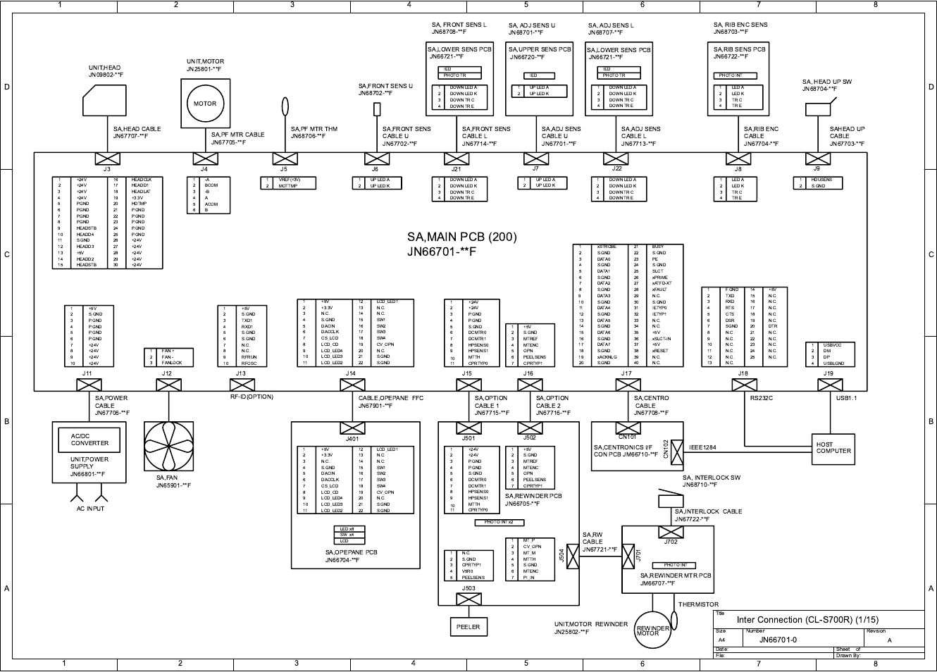
Chapter 6 Circuit Diagrams
CL-S700/CL-S703/CL-S700R 6-4
Inter Connection (Main PCB 1/15) (CL-S700R)
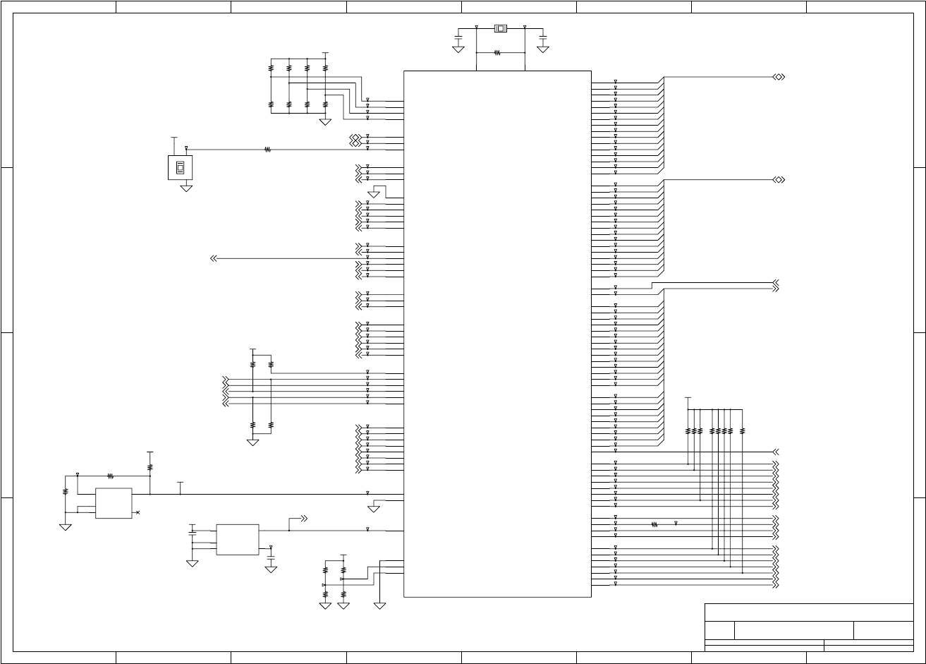
Chapter 6 Circuit Diagrams
6-5 CL-S700/CL-S703/CL-S700R
Circuit Diagram (Main PCB 2/15) [CPU (1)]
1 2 3 4 5 678
A
B
C
D
8
76
54321
D
C
B
A
Title
Number RevisionSize
A4
Date: Sheet of
File: Drawn By:
A
MAIN PCB - CPU (1)
JN66701-0
(2/15)
3R0V
2007/1/18
2007/1/18
2007/1/18
2007/1/18
2007/1/18
2007/1/18
2007/1/18
2007/1/18
2007/1/18
2007/1/18
2007/1/18
A[24:1]
D[15:0]
A24
A23
A22
A21
A20
A19
A18
A17
A16
A15
A14
A13
A12
A11
A10
A9
A8
A7
A6
A5
A4
A3
A2
A1
D31
D30
D27
D22
D18
D17
D16
D15
D14
D13
D12
D11
D10
D9
D8
D7
D6
D5
D4
D3
D2
D1
D0
D[31:16]
D19
D20
D21
D23
D24
D25
D26
D28
D29
SB V
GC
P65/INTP65/INTPC10/TIC1
19
P67/INTP67/TOC1
17 P66/INTP66/INTPC11
18
P72/DMARQ2/INTPC20/TIC2
176
P73/DMAAK2/INTPC21
175
P74/TC2/TOC2
174
P75/DMARQ3/INTPC30/TIC3
173
P76/DMAAK3/INTPC31
172
P77/TC3/TOC3
171
PCM0/WAIT
34
PCM1
33
PCM2/HLDAK
32
PCM3/HLDRQ
31
PCM4/REFRQ
30
PCM5/SELFREF/ADTRG
29
RESET
28
ANI0
5
ANI1
6
ANI2
7
ANI3
8
ANI4
9
ANI5
10
ANI6
11
ANI7
12
AVREFP
4
AVREFM
13
UDP
160 UDM
161
MODE1
15
MODE0
16
PLLSEL
156
PCT7/BCYST 77
PCT5/WE/WR 78
PCT4/RD 79
PCT3/UUWR/UUBE/UUDQM 80
PCT2/ULWR/ULBE/ULDQM 81
PCT1/LUWR/LUBE/LUDQM 82
PCT0/LLWR/LLBE/LLDQM 83
PCD3/SDRAS 86
PCD2/SDCAS 87
PCD1/BUSCLK 88
PCD0/SDCKE 91
D0 92
D1 93
D2 94
D3 95
D4 96
D5 97
D6 98
D7 99
D8 104
D9 105
D10 106
D11 107
D12 108
D13 109
D14 110
D15 111
PDH0/D16/INTPD0 112
PDH1/D17/INTPD1 113
PDH2/D18/INTPD2/TOC4 114
PDH3/D19/INTPD3 117
PDH4/D20/INTPD4 118
PDH5/D21/INTPD5/TOC5 119
PDH6/D22/INTPD6/INTP100/TCUD10 120
PDH7/D23/INTPD7/INTP101/TCLR10 121
PDH8/D24/INTPD8/TO10 122
PDH9/D25/INTPD9/TIUD10 123
PDH10/D26/INTPD10/INTP110/TCUD11 124
PDH11/D27/INTPD11/INTP111/TCLR11 125
PDH12/D28/INTPD12/TO11 126
PDH13/D29/INTPD13/TIUD11 127
PDH14/D30/INTPD14/PWM0 130
PDH15/D31/INTPD15/PWM1 131
PAL0/INTPL0/A0 76
PAL1/INTPL1/A1 75
A2 74
A3 73
A4 72
A5 69
A6 68
A7 67
A8 66
A9 65
A10 64
A11 63
A12 62
A13 61
A14 60
A15 59
PAH0/A16 58
PAH1/A17 57
PAH2/A18 52
PAH3/A19 51
PAH4/A20 50
PAH5/A21 49
PAH6/A22 48
PAH7/A23 47
PAH8/A24 46
PAH9/A25 45
PCS0/CS0 44
PCS1/CS1 43
PCS2/CS2/IOWR 42
PCS3/CS3 41
PCS4/CS4 40
PCS5/CS5/IORD 37
PCS6/CS6 36
PCS7/CS7 35
P55/TOC0/TC1
20 P54/INTPC01/DMAAK1
21 P53/INTPC00/TIC0/DMARQ1
22 P52/INTP52/TC0
23 P51/INTP51/DMAAK0
24 P50/INTP50/DMARQ0
25
P25/SO1/INTP25
145 P24/SI1/INTP24
146 P23/SCK1/INTP23
147 P22/TXD1/INTP22
148 P21/RXD1/INTP21
149 P20/NMI
152
P13/TXD0/SO0
153 P12/RXD0/SI0
154 P11/SCK0/INTP11
155
P10/UCLK/INTP10
159
X1 164
X2 165
JIT1
1
JIT0
2
SSEL1
169
SSEL0
170
VOUT 1
VDD
5
SUB
2
GND
4CT 3
A1
2
REF
1K3
A2
4NC 5
R33
22k
T76
T56
T37
T124
T42
T3
T16
T81
T74
C1
12p/50
T115
T39
T113
T101
T116
T112
T72
R13
*0
T41
R43 22k
T60
T121
T70
T8
R42 22k
T20
T28
T19
T117
R10
0T10
R31
22k
T11
R11
0
T83
T46
R12
0
T61
T12
T103
T68
T54
T59
T65
T86
T129
T34
T45
R21 0X2
FCXO-03L(48MHz)
1
2
4
3
T66
T30
T125
T40
T6
U1A
V850/ME2
T130
R53
0
T104
T22
T13
R40 22k
T64
T4
T18
T118
T123
T107
C3
0.1u/16
T52
X1 16MHz
T67
T87
C4
1000p/50
T44
T89
T108
R37 22k
R36 22k
T69
T63
T47
T106
U3
BD5328FVE
T93
T25
T90
R44
220
T21
R45 20k/1%
T71
T57
R49
*0
T111
T49
T91
T23
T14
R46
100k/1%
T5
R1 1M
T102
T62
T73
R48 0
T32
R32
22k
T38
T92
T1
T51
T126
R41 22k
T109
U2
uPC1093TA T119
T75
T50
T94
T2
T105
T122
T27
T85
R193
0
R30
22k
T43
T377
T95
T24
T96
T29
T15
R38 22k
T33
T7
R2
*0
T79
R3
*0
R4
*0
T88
T53
T128
R194
*0
T114
T97
T110
T55
T98
T120
T100
T58
T48
T36
T80
T127
T82
T78
T84
T31
T26
T99
R5
0
R39 22k
T35
T17
C2
12p/50
T77
T9
V5R0
VREF
V3R3
V3R3
V3R3
V3R3
V3R3
V3R3
CEREQ16
HEREQ06
SENSFIX9
SENSMOVE9
HDTMP7
VHEADMON7
MOTTMP8
HEADRES7
MTTH12
PEELSENS12
RXD111
PLDRXDO6
FANLOCK10
MTENC12
RFOSC11
LDSR014
OPINTP6
HDINTP6
CNINTP6
UBINTP15
HDUSENS9
OPN12
RIBSENS 9
UDM15
UDP15
D[15:0] 4,5,6
D[31:16] 5
SDCKE 5
ITV6
DACCLK3,11
PFCLK6,8
DACIN3,11
BUZZER10
-ROM2CS 4
-SDRAMCS 5
CEACK16
HEACK06
-IOWR 6
-RD 4,6
-IORD 6
-GRESET6,8,13
-SDCAS 5
-SDRAS 5
BUSCLK 5,6
LLDQM/-LLBE 4,5,6
LUDQM/-LUBE 4,5,6
-GACS 6
-WE/-WR 5
A[24:1] 4,5,6
TXD111
TXD014
-ROM1CS 4
RESET 10,14
ULDQM/-ULBE 5
UUDQM/-UUBE 5
LDTR014
USBON15
FANCTL 10
DCMTR0 12
DCMTR1 12
RFRUN11
RIBENC 9
CV_OPN11
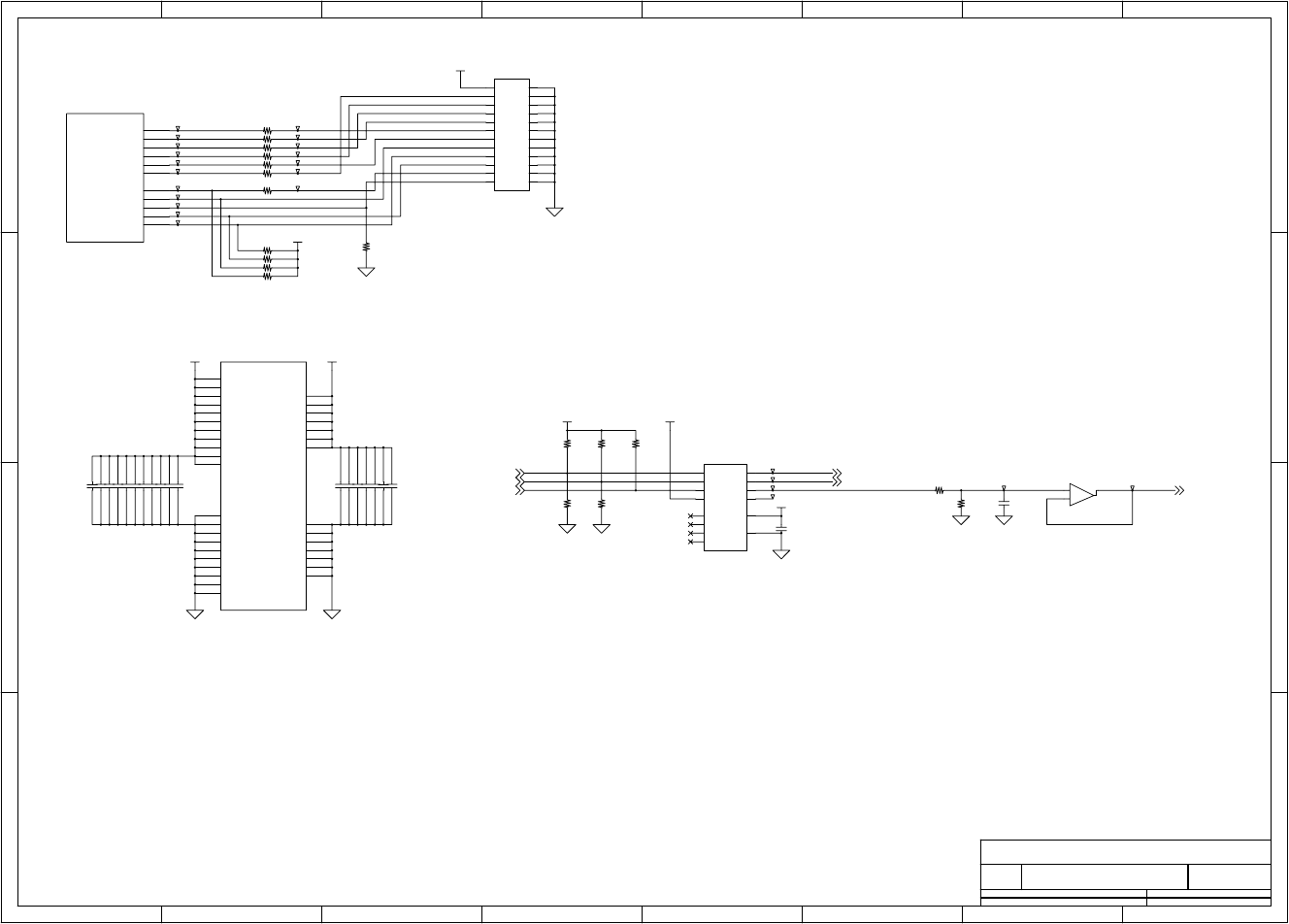
Chapter 6 Circuit Diagrams
CL-S700/CL-S703/CL-S700R 6-6
Circuit Diagram (Main PCB 3/15) [CPU (2)/DAC]
1 2 3 4 5 678
A
B
C
D
8
76
54321
D
C
B
A
Title
Number RevisionSize
A4
Date: Sheet of
File: Drawn By:
A
MAIN PCB - CPU (2) / DAC
JN66701-0
(3/15)
TRCDATA2
TRCDATA0
TRCEND
TRCDATA3
DRSTZ
TRCCLK
DDO
DCK
DDI
DMS
TRCDATA1
IVDD 26
IVDD 55
IVDD 84
IVDD 102
IVDD 134
IVDD 157
PLLVDD 167
IVSS 27
IVSS 56
IVSS 85
IVSS 103
IVSS 135
IVSS 158
PLLVSS 168
EVDD
38
EVDD
53
EVDD
70
EVDD
89
EVDD
100
EVDD
115
EVDD
128
EVDD
150
AVDD
3
OSCVDD
163
EVSS
39
EVSS
54
EVSS
71
EVSS
90
EVSS
101
EVSS
116
EVSS
129
EVSS
151
AVSS
14
OSCVSS
166
UVDD
162
2
31
1 2
3 4
5 6
7 8
9 10
11 12
13 14
15 16
17 18
19 20
21 22
23 24
CSB
10
DI
12
CLK
11
TM1
3
VSS 14
VDD 9
AO1 1
AO2 2
TM2
4
AO3 5
AO4 6
NC1
7
VFS
13
NC2
8
TRCDATA3 132
TRCDATA2 133
TRCDATA1 136
TRCDATA0 137
TRCEND 138
TRCCLK 139
DDO 140
DDI 141
DRST 142
DMS 143
DCK 144
R59 0
C7 0.1u/16
C22 0.1u/16
T147
U1B
V850/ME2
C9 0.1u/16
R58 0
R57 0
C10 0.1u/16
T138
C24
0.1u/16
T149
C18 0.1u/16
T150
R56 0
T139
R195
22k
T141
T152
C13 0.1u/16
C23
1000p/50
U5A
BA2904
-
+
T137
R63 4.7k
T143
R55 0
J1
24FLT
C21 0.1u/16
C5 0.1u/16
U4
BH2227
U1C
V850/ME2
T144
C16 0.1u/16
T135
T145
T146
R68
22k
C17 0.1u/16
T140
C12 0.1u/16
T155
T134
R64 4.7k
C20 0.1u/16
T148
C15 0.1u/16
C8 0.1u/16
R67
22k
R62
22k
T133
C11 0.1u/16
T136
R66
*22k
R192
*22k
C19 0.1u/16
T153
C6 0.1u/16
T154
T132
R61 4.7k
T142
R54 0
C14 0.1u/16
R65 4.7k
R196
*22k
R60 0
R69 22k
T151
V3R3
V1R5
V3R3
V3R3
V3R3 VREF
V5R0
DACIN2,11
DACCLK2,11
CS_DAC6
PFMOTCU 8
PESNSLED 9
MTREF 12
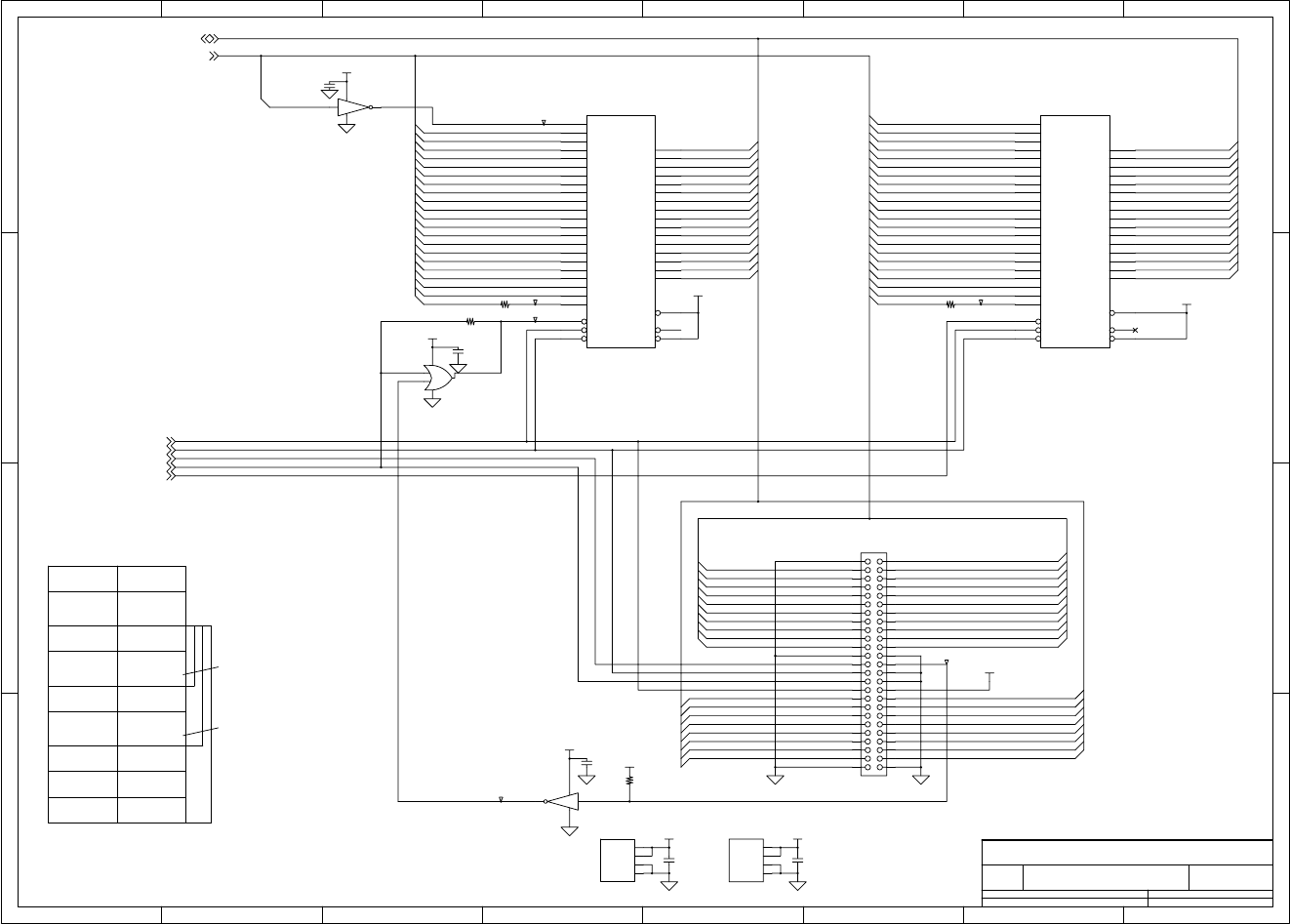
Chapter 6 Circuit Diagrams
6-7 CL-S700/CL-S703/CL-S700R
Circuit Diagram (Main PCB 4/15) [ROM]
1 2 3 4 5 678
A
B
C
D
8
76
54321
D
C
B
A
Title
Number RevisionSize
A4
Date: Sheet of
File: Drawn By:
A
MAIN PCB - ROM
JN66701-0
(4/15)
200000h
100000h
300000h
400000h
Program ROM Address
300000h
200000h
(000000h)
500000h
600000h
700000h
000000h
(N/A)
400000h
(000000h)
500000h
600000h
700000h
For 16M
For 32M
For 64M
(Highre order 8M is not available.)
CPU Address ROM Address
100000h
--
A1
LUDQM/-LUBE
LLDQM/-LLBE
-ROM1CS
A21
A1
A3
A5
A7
A15
A9
A11
A13
A17
A19
A14
A8
A12
A20
A2
A4
A6
A18
A10
A16
D14
D12
D10
D8
D6
D4
D2
D0
D15
D9
D11
D13
D5
D1
D7
D3
-RD
D[15:0]
D5
A17
D6
A12
D2
D14
D10
A18 D15
D3
A15
D8
D0
A13
D11
A14
A21
D13
D7
A16
D1
D4
D9
A19
D12
A20
A8
A7
A6
A5
A4
A3
A10
A3
A9
A1
A5
A8
A6
A11
A7
A2
A4
D15
D5
D11
D9
D8
D4
D14
D7
D2
D3
D6
D13
D10
D12
D1
D0
A19
A18
A11
A13
A21
A14
A10
A15
A9
A16
A12
A17
A[24:1]
A2
A22
A22
A20
D15 45
A 1
25 A 2
24 A 3
23 A 4
22 A 5
21 A 6
20 A 7
19 A 8
18 A 9
8A10
7A11
6A12
5A13
4A14
3A15
2A16
1A17
48 A18
17
CE
26
OE
28
BYTE 47
D 0 29
D 1 31
D 2 33
D 3 35
D 4 38
D 5 40
D 6 42
D 7 44
WE
11 RESET 12
RY/BY 15
A19
16
D14 43
D13 41
D12 39
D11 36
D10 34
D 9 32
D 8 30
A20
9A21
10
NC
13
VCC1 14
GND2 46
VCC2 37
GND1 27
2 4
5
3
VCC1 14
GND2 46
VCC2 37
GND1 27
D15 45
A 0
25 A 1
24 A 2
23 A 3
22 A 4
21 A 5
20 A 6
19 A 7
18 A 8
8A 9
7A10
6A11
5A12
4A13
3A14
2A15
1A16
48 A17
17
CE
26
OE
28
BYTE 47
D 0 29
D 1 31
D 2 33
D 3 35
D 4 38
D 5 40
D 6 42
D 7 44
WE
11 RESET 12
RY/BY 15
A18
16
D14 43
D13 41
D12 39
D11 36
D10 34
D 9 32
D 8 30
A19
9A20
10
A21
13
A1
A2
A3
A4
A5
A6
A7
A8
A9
A10
A11
A12
A13
A14
A15
A16
A17
A18
A19
A20
A21
A22
A23
A24
A25
B1
B2
B3
B4
B5
B6
B7
B8
B9
B10
B11
B12
B13
B14
B15
B16
B17
B18
B19
B20
B21
B22
B23
B24
B25
24
53
U7A
W19B320ATT7M
U8B
*S29JL064H70TFI000
R73
*3.3k
U6
TC7SH04
V
G
N
T161
R70 *0
T159
C28
0.1u/16
U7B
W19B320ATT7M
U8A
*S29JL064H70TFI000
J2
*8830E-050
T160
T156
U9
*7SH32
V5
G3
1
24
U10
*TC7SH04
V
G
N
C25
0.1u/16
R71 0
T157 T158
C29
0.1u/16
C27
*0.1u/16
R72 0
C26
*0.1u/16
V3R3
V3R3
V3R3
V3R3
V3R3
V3R3
V3R3
V3R3
V3R3
A[24:1]2,5,6
-ROM2CS2
-ROM1CS2
-RD2,6
LLDQM/-LLBE2,5,6
LUDQM/-LUBE2,5,6
D[15:0]2,5,6
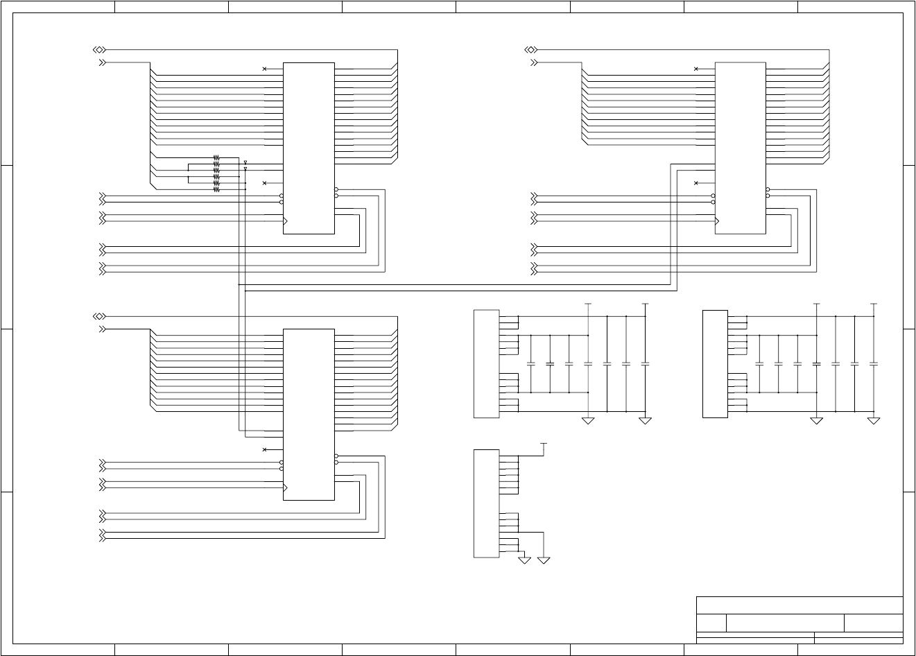
Chapter 6 Circuit Diagrams
CL-S700/CL-S703/CL-S700R 6-8
Circuit Diagram (Main PCB 5/15) [RAM]
1 2 3 4 5 678
A
B
C
D
8
76
54321
D
C
B
A
Title
Number RevisionSize
A4
Date: Sheet of
File: Drawn By:
A
MAIN PCB - RAM
JN66701-0
(5/15)
D[15:0]
A12
A11
A10
A9
A8
A7
A6
A5
D15
D14
D13
A4
D12
D11
D10
A3
D9
D8
A[24:1]
D7
A2
D6
D5
D4
A1 D3
D2
D1
D0
A13
D[31:16]
A13
A12
A11
A10
A9
A8
A7
A6
D31
D30
D29
A5
D28
D27
D26
A4
D25
D24
A[24:1]
D23
A3
D22
D21
D20
A2 D19
D18
D17
D16
A13
A12
A11
A10
A9
A8
A7
A6
A5
A4
A[24:1]
A3
A2
D[15:0]
D15
D14
D13
D12
D11
D10
D9
D8
D7
D6
D5
D4
D3
D2
D1
D0
A23
A22
A21
A24
VDDQ 9
VSSQ 52
VDD 1
VDD 14
VDD 27
VDDQ 3
VDDQ 43
VSSQ 6
VSSQ 12
VSSQ 46
VSS 28
VSS 41
VDDQ 49
VSS 54
VDDQ 9
VSSQ 52
VDD 1
VDD 14
VDD 27
VDDQ 3
VDDQ 43
VSSQ 6
VSSQ 12
VSSQ 46
VSS 28
VSS 41
VDDQ 49
VSS 54
VDDQ 9
VSSQ 52
VDD 1
VDD 14
VDD 27
VDDQ 3
VDDQ 43
VSSQ 6
VSSQ 12
VSSQ 46
VSS 28
VSS 41
VDDQ 49
VSS 54
DQ0 2
DQ1 4
DQ2 5
DQ3 7
DQ4 8
DQ5 10
DQ6 11
DQ7 13
DQ8 42
A0
23 A1
24 A2
25 A3
26 A4
29 A5
30 A6
31 A7
32 A8
33 A9
34 A10
22 A11
35
DQ9 44
DQ10 45
DQ11 47
DQ12 48
DQ13 50
DQ14 51
DQ15 53
CLK
38 CKE
37
CAS 17
RAS 18
LDQM 15
UDQM 39
WE
16 CS
19
BS0
20
BS1
21
NC(A12)
36
NC
40
DQ0 2
DQ1 4
DQ2 5
DQ3 7
DQ4 8
DQ5 10
DQ6 11
DQ7 13
DQ8 42
A0
23 A1
24 A2
25 A3
26 A4
29 A5
30 A6
31 A7
32 A8
33 A9
34 A10
22 A11
35
DQ9 44
DQ10 45
DQ11 47
DQ12 48
DQ13 50
DQ14 51
DQ15 53
CLK
38 CKE
37
CAS 17
RAS 18
LDQM 15
UDQM 39
WE
16 CS
19
BA0
20
BA1
21
NC(A12)
36
NC
40
DQ0 2
DQ1 4
DQ2 5
DQ3 7
DQ4 8
DQ5 10
DQ6 11
DQ7 13
DQ8 42
A0
23 A1
24 A2
25 A3
26 A4
29 A5
30 A6
31 A7
32 A8
33 A9
34 A10
22 A11
35
DQ9 44
DQ10 45
DQ11 47
DQ12 48
DQ13 50
DQ14 51
DQ15 53
CLK
38 CKE
37
CAS 17
RAS 18
LDQM 15
UDQM 39
WE
16 CS
19
BS0
20
BS1
21
NC(A12)
36
NC
40
C36
0.1u/16
R79 *0
R75 0
R77 *0
U11B
W9864G6EH-7
C34
0.1u/16
C32
0.1u/16
C41
0.1u/16
C30
0.1u/16
T162
R76 *0
C38
0.1u/16
R78 0
C35
0.1u/16
U13B
*HY57V281620E
R74 *0
C33
0.1u/16
C43
0.1u/16
U12B
W9864G6EH-7
C31
0.1u/16
C40
0.1u/16
U11A
W9864G6EH-7
U13A
*HY57V281620E
U12A
W9864G6EH-7
T163
C37
0.1u/16
C42
0.1u/16
C39
0.1u/16
V3R3V3R3 V3R3V3R3
V3R3
A[24:1]2,4,6
-SDRAS2
SDCKE2
LUDQM/-LUBE2,4,6
LLDQM/-LLBE2,4,6
-SDCAS2
BUSCLK2,6
-SDRAMCS2
-WE/-WR2
-SDRAMCS2
-WE/-WR2
BUSCLK2,6
A[24:1]2,4,6
-SDRAS2
SDCKE2
UUDQM/-UUBE2
ULDQM/-ULBE2
-SDCAS2
-SDRAMCS2
-WE/-WR2
BUSCLK2,6
A[24:1]
2,4,6
-SDRAS2
SDCKE2
-SDCAS2
LUDQM/-LUBE2,4,6
LLDQM/-LLBE2,4,6
D[15:0]2,4,6
D[31:16]2
D[15:0]2,4,6
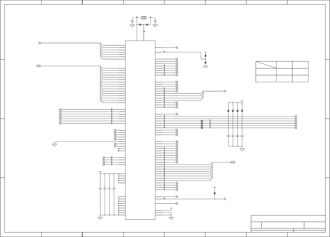
Chapter 6 Circuit Diagrams
6-9 CL-S700/CL-S703/CL-S700R
Circuit Diagram (Main PCB 6/15) [Custom IC]
1 2 3 4 5 678
A
B
C
D
8
76
54321
D
C
B
A
Title
Number RevisionSize
A4
Date: Sheet of
File: Drawn By:
A
MAIN PCB - CUSTOM IC
JN66701-0
(6/15)
R82 R83
0
NA
NA
CPU
CRYSTAL 0
- Input Clock Setting for GATE ARRAY
A2
A16
A18
A17
A[24:1]
A1
A3
A4
DATA[7:0]
D12
D3
D9
D10
D4
D7
D14
D15
D8
D11
D5
D[15:0]
D13
D2
D1
D0
D6
HD[4:1]
HD4
HD3
HD2
HD1
DATA6
DATA7
DATA5
DATA4
DATA3
DATA2
DATA1
DATA0
Xin 2
Xout 3
GND
4
VDD
5
RXDOUT 6
OPINTP 7
CNINTP 8
HDINTP 9
CNREQ1 10
CNACK1 11
HDACK0 13
PFCLK 14
GND
15
ITV
16
IORD
17
IOWR
18
CS
19
LLBE
22
LUBE
23
RD
20
SCK
21
STROBE 58
PLH 59
GND
60
VDD
61
FAULT 62
SELECT 63
DATA7 64
DATA5 66
DATA4 67
DATA3 68
DATA2 69
DATA1 70
DATA0 71
LWR
24
A18
27
A17
28
TEB 29
VDD
30
GND
31
A16
32
A2
35 A3
34
A1
36
D15
37
D14
38
D13
39
D10
42
D9
43
D8
44
GND
45
D7
46
D6
47
D5
48
D4
49
D1
52
D0
53
RXDIN 54
SELECTIN 55
INIT 56
OPD3
80
OPRD
78
OPE
79
OTDIR 76
PM3
98
PM1
96
VDD
90
SW1 89
SW2 88
SW3 87
SW6 84
OPD0
83 OPD1
82
LED1 94
PM0
95
LED3 92
LED2 93
GND
91
OPD2
81
PFCNT1 99
D12
40
D3
50
D2
51
AUTOFD 57
OPRS
77
DATA6 65
GND
75
SW5 85
PM2
97
VDD
1
HWR
25
D11
41
RESET 26
A4
33
HDREQ0 12
SW4 86
PFCNT2 100
PEND 72
BUSY 73
PFMXB 101
PFMXA 102
PFMB 103
PFMA 104
PFON 105
GND
106
HDLTH 107
HDSTB 108
HDATA4 109
HDATA3 110
HDATA2 111
SMC 112
HDATA1 113
CLKSEL 114
HDCLK 115
HDVON 116
HCVON 117
AMC 118
CLKIN 119
GND
120
ACK 74
T195
T212
T165
T224
R91 1k
X3 *16MHz
R86 22k
C60 0.1u/16
T202
C53 1000p/50
R80
*1M
T220
U14
U_GA_uPD65946GJ-165-3EB-A
T196
T197
T169
T206
R81
*1M
T213
R90 1k
T215
T164
T179
T185
T189
T216
T170
T214
T176
T181
R89 1k
C51
12p/50
T182
T217
T166
T171
R85 22k
T199
T208
T180
T183
T194
C58 0.1u/16
C56 1000p/50
T225
T200
T188
T168
R88 1k T193
T177
T218
R87 22k
T190
R82
0
R83
*0
T167
R92
22k
T207
T172
C59 0.1u/16
C55 1000p/50
T205
T210
T192
C52
*12p/50
T204
T187
T209
T174
T219
T198
T221
T175
T222
C57 0.1u/16
T211
T203
T178
T223
R84 22k
T184
T191
C54 1000p/50
V3R3
V3R3
V3R3
V3R3
V3R3
PFCLK 2,8
-RD2,4
LLDQM/-LLBE2,4,5
-GACS2
LUDQM/-LUBE2,4,5
BUSCLK 2,5
SW1 11
SW2 11
SW3 11
SW4 11
ITV2
-IORD2
A[24:1]2,4,5
-IOWR2
CEACK1 2
-GRESET 2,8,13
HEACK0 2
PLDRXDI 14
xSTROBE 13
xSLCT-IN 13
xATFD-XT 13
xPRIME 13
IETYP113
IETYP013
CPRTYP012
CPRTYP112
HPSENS0 12
HPSENS1 12
D[15:0]2,4,5
DATA[7:0] 13
SLCT 13
OPINTP 2
PFON 8
HD[4:1] 7
HDINTP 2
HDVON 7
HCVON 7
-HDLAT 7
-HDSTB 7
HDCLK 7
CEREQ1 2
CNINTP 2
HEREQ0 2
PFMB 8
-PFMB 8
PFMA 8
-PFMA 8
PLDRXDO 2
xFAULT 13
PLH 13
xACKNLG 13
PE 13
BUSY 13
OBDIR 13
LEDFIX_R 9
LEDFIX_T 9
LEDMOVE_R 9
LEDMOVE_T 9
LCD_LED411
CS_DAC3
CS_LCD11
LCD_CD11
LCD_LED311
LCD_LED211
LCD_LED111
V5ON 10
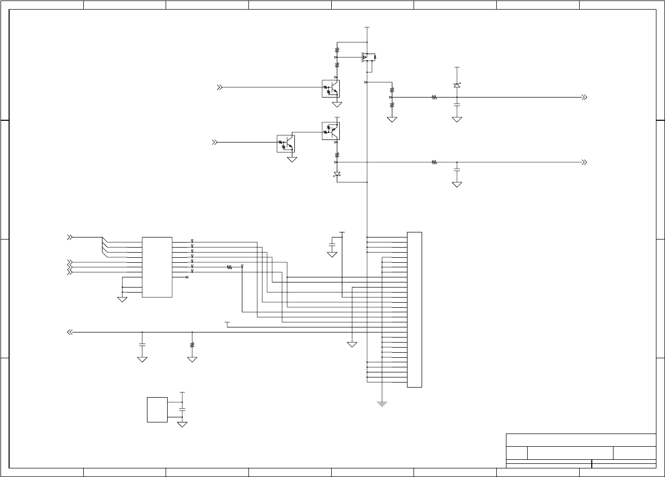
Chapter 6 Circuit Diagrams
CL-S700/CL-S703/CL-S700R 6-10
Circuit Diagram (Main PCB 7/15) [Head Control]
1 2 3 4 5 678
A
B
C
D
8
76
54321
D
C
B
A
Title
Number RevisionSize
A4
Date: Sheet of
File: Drawn By:
A
MAIN PCB - HEAD CONTROL
JN66701-0
(7/15)
HEADRES
VHDON
HD1
HD2
HD3
HD[4:1]
HD4
HEADLAT
HEADD1
HEADD2
HEADSTB
HEADD3
HEADD4
HEADSTB
HEADCLK
VCC 20
GND 10
1
2
3
4
5
6
7
8
9
10
11
12
13
14
15
16
17
18
19
20
21
22
23
24
25
26
27
28
29
30
1
23
4
A1
2
A2
4
A3
6
A4
8
1OE
1
Y1 18
Y2 16
Y3 14
Y4 12
A5
11
A6
13
A7
15
A8
17
Y5 9
Y6 7
Y7 5
Y8 3
2OE
19
T228
R102
30k/1%
T226
T229
R97
3.3k/1%
T234
T232 C63
10u/10
R94
10k
T237
Q29
DTC114EM
10k
10k
C61
*1000p/50
T227
T231
T235
U15B
74HCT244
J3
S30B-PHDSS
Q1
2SJ505S
G
D
S
R95
30k/1%
D2
RB521S
Q3
DTA114EM
10k
10k
D1
RB521S
T230
C64
*1000p/50
R96 1k
C62
*1000p/50
T239
C65
0.1u/16
Q2
DTC114EM
10k
10k
U15A
74HCT244
T236
T238
R93
10k
T233
R99
100/1%/2012
R100 1k
R101 0
V24R0
V5R0
V3R3
V5R0
V3R3
V3R3
-HDLAT6
HDCLK6
-HDSTB6
HD[4:1]6
HCVON6
HDVON6
HDTMP2
HEADRES 2
VHEADMON 2
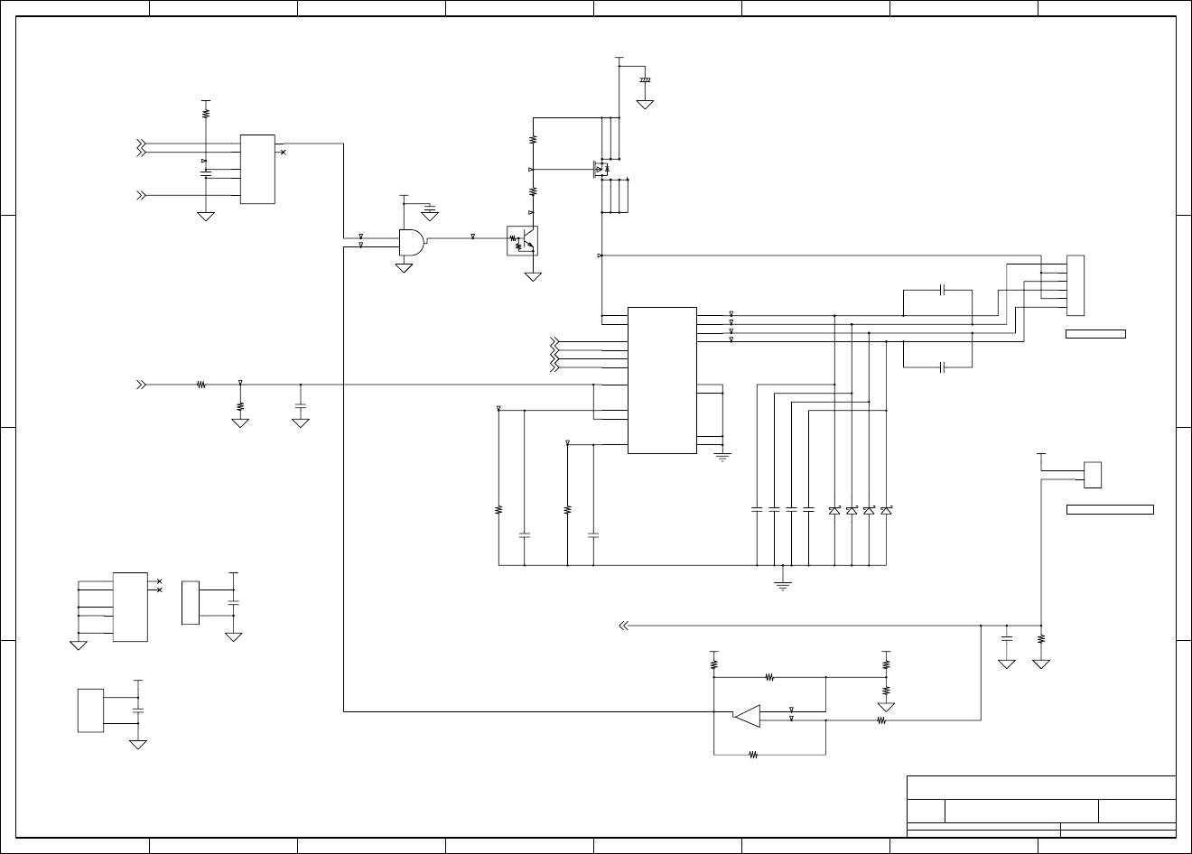
Chapter 6 Circuit Diagrams
6-11 CL-S700/CL-S703/CL-S700R
Circuit Diagram (Main PCB 8/15) [PF Motor Control]
1 2 3 4 5 678
A
B
C
D
8
76
54321
D
C
B
A
Title
Number RevisionSize
A4
Date: Sheet of
File: Drawn By:
A
MAIN PCB - PF MOTOR CONTROL
JN66701-0
(8/15)
PF MOTOR THRM
PF MOTOR
BCOM
ACOM
-A
-B
A
B
PFMTCOM
TMPOFF
OUTA
-OUTA
OUTB
-OUTB
V+ 8
V- 4
A
9
B
10
CLR
11
CX
6RX/CX
7
Q12
Q5
G8
V16
2
31
A
1
B
2
CLR
3
CX
14 RX/CX
15
Q4
Q13
1
2
3
4
5
6
TDA 2
INA
6
INA
5
INB
17
INB
16
RSA
9
REFA
3
GB 15
GA 4
OUTA 8
OUTA 1
OUTB 18
OUTB 11
TDB 13
VSA
7
VSB
12
RSB
10
REFB
14
1
2
4
51
6
7
2
3
8
R114
3.3k/1%
T247
U19C
uPC393GR-9LG
T249
R103
200k
T251
C70
100p/100
C80
0.1u/16
C71
0.1u/16
T242
T253
R111
3.3k/1%
T255
U16B
74VHC123
C72 100p/100
C68
0.1u/16
R115 1k
D5 *SFPB66
U16C
74VHC123
R107
20k/1%
R110
3.3k/1%
T254
R109 0.68/2%/3W
D4 *SFPB66
T245
T250
Q5
DTC114EM
10k
10k
R112
1k/1%
R116 *3.3k
C77
100p/50
T243
R104
10k
C76
100p/50
U19A
uPC393GR-9LG
+
-
D3 *SFPB66
D6 *SFPB66
T240
T252
R113 100k
C69
100p/100
C67
1u/B16
U17
74AHC1G08
V5
G3
1
24
C73 100p/100
U16A
74VHC123
T244
T246
J4
B6B-EH-*
T241
R105
10k
C79
0.1u/16
C74 100p/100
T248
R108 0.68/2%/3W
R106 20k/1%
C78
1000p/50
U18
U_MTR_SLA7033MPR
C75 100p/100
J5
B2B-PH-K-S
C66
100u/50
+
Q4
XP132A11A1
V24R0
V3R3
V3R3
V3R3
VREF
VREF
VREF
V3R3
-GRESET2,6,13
PFCLK2,6
PFMOTCU3
PFMA6
-PFMA6
PFMB6
-PFMB6
PFON6
MOTTMP2
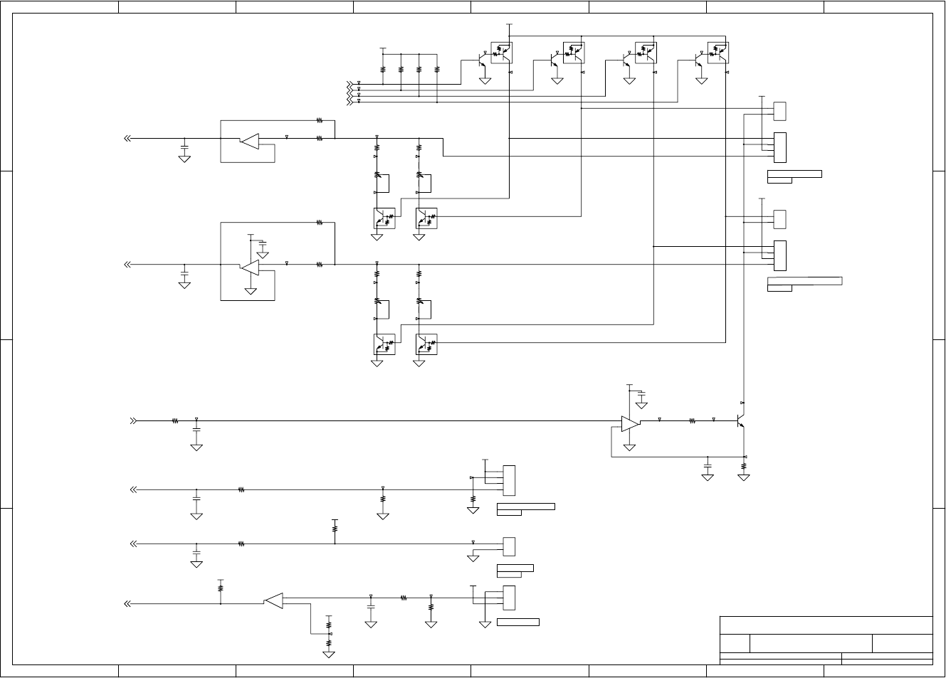
Chapter 6 Circuit Diagrams
CL-S700/CL-S703/CL-S700R 6-12
Circuit Diagram (Main PCB 9/15) [Sensor]
1 2 3 4 5 678
A
B
C
D
8
76
54321
D
C
B
A
Title
Number RevisionSize
A4
Date: Sheet of
File: Drawn By:
A
MAIN PCB - SENSOR
JN66701-0
(9/15)
DOWN LED K
DOWN LED A
DOWN TR C
DOWN TR E
DOWN LED K
DOWN LED A
DOWN TR C
DOWN TR E
UP LED K
UP LED A
FIX LED/SENSOR
RIBBON ENCODER
LED K
LED A
TR C
TR E
HEAD UP
ADJUSTABLE LED/SENSOR
UP LED K
UP LED A
RIBBON END
Blue
Red
Black
Black
2
31
1
2
3
31
2
8
75
6
4
75
6
31
2
1
2
3
4
1
2
1
2
1
2
3
4
31
2
1
2
1
2
3
4
31
2
8
75
6
4
Q26
2SC5658
C83
1000p/50
Q18
DTC114EM
10k
R120 100
C85
1000p/50
T262
T270
C87
1000p/50
R130
100
R127
75/1%/2012
T274
U20A
*BA2904
-
+
Q19
DTC114EM
10k
10k
R200
22k
T366
C88
1000p/50
C82
*0.1u/16
C86
*1000p/50
T364
R207
3.3k
J10
B3B-PH-K-S
T273
T260
Q25
2SC5658
VR4
10k
T256
R132 1k
U20B
*BA2904
V+
V-
-
+
T267
R206
3.3k
Q10
2SC5658
R124
3.3k
C89
1000p/50
T371
R208
3.3k
R135
10k
U19B
uPC393GR-9LG
+
-
R134
1M
Q20
DTC114EM
10k
T261
T275
Q9
DTA114EM
10k
T279
R117 100
VR3
10k
T369
T380
T266
R121
3.3k
T264
R129
10k
R125 22k
J8
B4B-PH-K-K
R118 *100
T272
J9
B2B-PH-K-K
Q7
DTA114EM
10k
J7
B2B-PH-K-R
R203
22k
T280
T265
T269
J21
B4B-PH-K-E
VR2
10k
J6
B2B-PH-K-E
R202
22k
T263
R122 *100
R133 1k
J22
B4B-PH-K-R
VR1
10k
T370
R126 200
T281
T278
R136
10k
T379
C84
0.1u/16
T258
C81
1000p/50
R201
22k T257
T365
T368
U5B
BA2904
V+
V-
-
+
Q21
DTC114EM
10k
Q28
2SC5658 T259
T367
R131
22k
T271
T268
Q27
2SC5658
R128 1k
Q8
DTA114EM
10k
Q6
DTA114EM
10k
T276
V3R3
V3R3
V5R0
V3R3
V3R3
V5R0
V3R3
V3R3
V5R0
V3R3
V3R3
LEDFIX_T6
LEDFIX_R6
PESNSLED3
LEDMOVE_T6
LEDMOVE_R6
RIBENC2
SENSFIX2
SENSMOVE2
HDUSENS2
RIBSENS2
10k
10k
10k
10k
10k
10k
10k
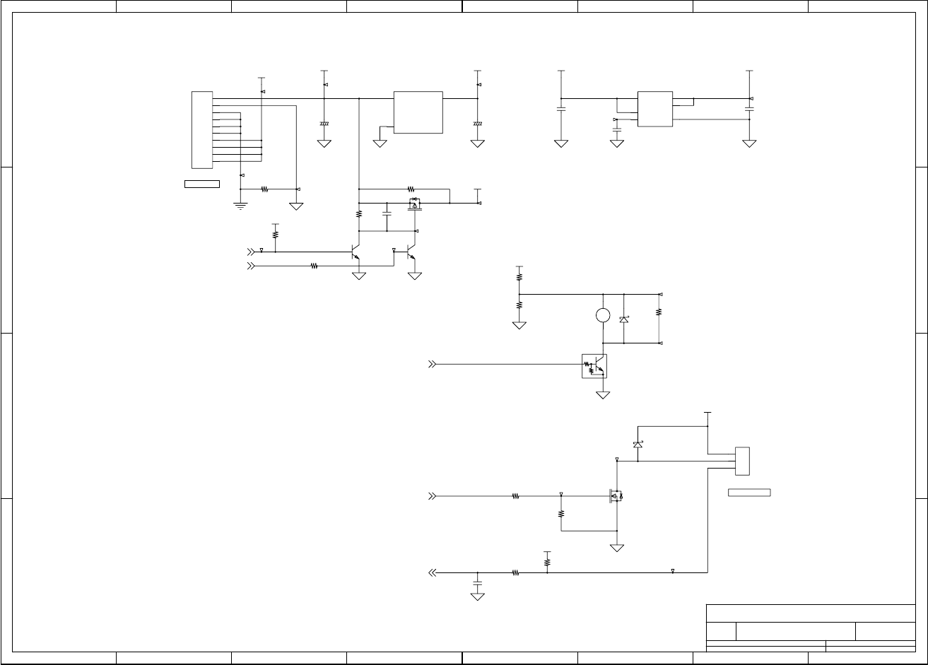
Chapter 6 Circuit Diagrams
6-13 CL-S700/CL-S703/CL-S700R
Circuit Diagram (Main PCB 10/15) [Power/Buzzer/Fan]
1 2 3 4 5 678
A
B
C
D
8
76
54321
D
C
B
A
Title
Number RevisionSize
A4
Date: Sheet of
File: Drawn By:
A
MAIN PCB - POWER / BUZZER / FAN
JN66701-0
(10/15)
POWER
FAN CNT
Vin
1Vout 3
GND
2VSS 5
VI
1O1 2
STB
6
N
4
O2 3
12
1
2
3
1
2
3
4
5
6
7
8
9
10
R143
22k
R197
*10k
U26
NJM2391DL1-33
R142 1k
C90
1u/B16
T288
T376
R140
3.3k/3216
C94
47u/35
+
D7
RB521S
C92
0.1u/16
Q12
2SK3577
C114
*0.1u/16
Q24
*2SC5658
R137 0/2012
C93
47u/35
+
R198
*22k
R145 1k
R144
22k
T284
T372
C95
1000p/50
T286
U21
BH15MA3WHFV
T373
T293
T294
R204 0/2012
T287
T283
T374
Q23
*2SC5658
T282
T290
BZ1
PKM13EPYH4002-B0
+
T289
T375
J12
B3B-EH-K
C91
1u/B16
R199 *10k
T291
Q11
DTC114EM
10k
10k
Q22
*2SJ518
R141
1k/3216
D8
SFPB66
R138
240/3216
J11
B10B-EH
V3R3
V5
V24R0
V3R3
V24R0
V3R3 V1R5
V24R0
V5R0
V3R3
BUZZER2
FANCTL2
FANLOCK2
RESET2,14
V5ON6
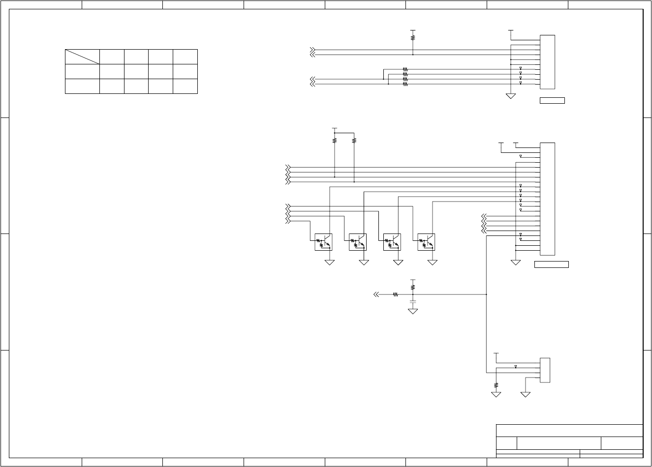
Chapter 6 Circuit Diagrams
CL-S700/CL-S703/CL-S700R 6-14
Circuit Diagram (Main PCB 11/15) [RFID/Ope-Pane]
1 2 3 4 5 678
A
B
C
D
8
76
54321
D
C
B
A
Title
Number RevisionSize
A4
Date: Sheet of
File: Drawn By:
A
MAIN PCB - RFID / OPE-PANE
JN66701-0
(11/15)
Custom Type
R147
Jumber Setting for each RF-ID module
Standard
0
R148 R149
NA
R150
RXD1
TXD1
RF-ID
RFRUN
OPE PANE
RFOSC
NA
NA NA0
00
1
2
3
4
1
2
3
4
5
6
7
8
9
10
20
11
19
12
18
13
17
14
16
15
21
22
1
2
3
4
5
6
7
8
9
10
Q16
DTC114EM
10k
10k
T303
R150 0
T300
Q15
DTC114EM
10k
T298
T295
T296
T378
Q14
DTC114EM
10k
R149 0
J20
B4B-PH-K-S
R205
180/2012
C113
1000p/50
T304
J14
22FMN-BMT-A-TF
T306
R191 1k
T301
R148 *0
R190
22k
Q13
DTC114EM
10k
R147 *0
T297
R146
22k
J13
B10B-ZR
R152
22k
T302
T305
R151
22k
T307
T299
V3R3
V5R0
V5R0
V3R3
V3R3
V3R3
V5R0
TXD12
DACIN2,3
DACCLK2,3
CS_LCD6
LCD_CD6
LCD_LED16
LCD_LED26
LCD_LED36
LCD_LED46
RXD12
RFRUN2
SW26
SW46
SW16
SW36
RFOSC2
CV_OPN2
10k
10k
10k
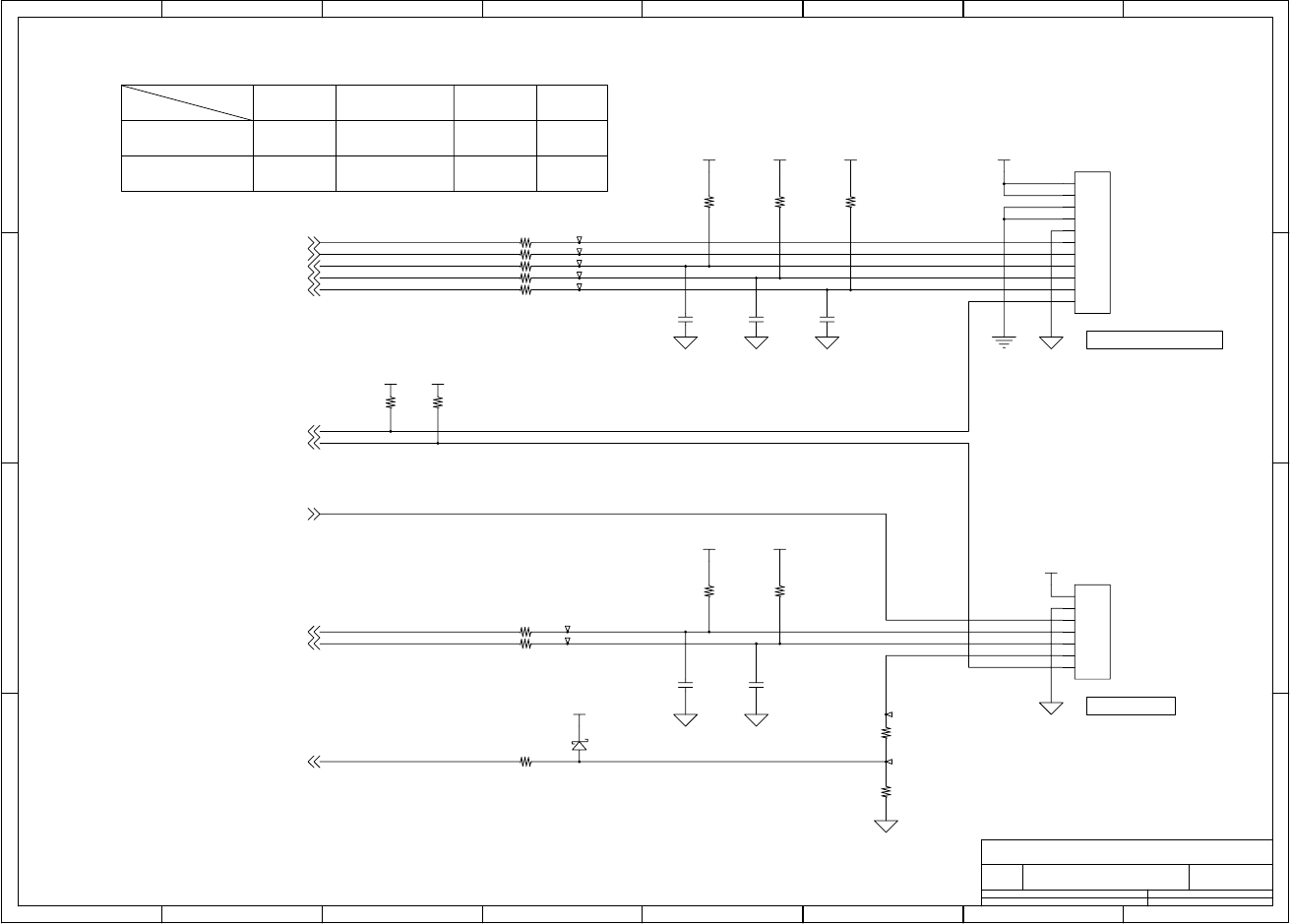
Chapter 6 Circuit Diagrams
6-15 CL-S700/CL-S703/CL-S700R
Circuit Diagram (Main PCB 12/15) [Cutter/Rewinder]
1 2 3 4 5 678
A
B
C
D
8
76
54321
D
C
B
A
Title
Number RevisionSize
A4
Date: Sheet of
File: Drawn By:
A
MAIN PCB - CUTTER/REWINDER
JN66701-0
(12/15)
HighHigh
CPRTYP1 Low HighHigh
Low
Cutter Rewinder None
Option Select
CUTTER & REWINDER
REWINDER
Low
Low
Peeler
CPRTYP0
1
2
3
4
5
6
7
1
2
3
4
5
6
7
8
9
10
11
D9
*RB521S
R164
22k
R161
1k
R155
3.3k/1%
J16
B7B-PASK
T311
R165 100
T308
T309
R166 100
C100
1000p/50
R153
22k
R157 1k
R159 1k
C99
1000p/50
R156 1k
R168 100
R162
1k
R160 100
C96
1000p/50
T313
T310
T315
T316
T317
J15
B11B-PASK
R167
2.4k/1%
R158 1k
R154
22k
C97
1000p/50
R163
22k
C98
1000p/50
R169
3.3k/1%
T312
V3R3V3R3
V3R3 V24R0
V3R3 V3R3
V5R0
V3R3
V3R3 VREF
DCMTR02
DCMTR12
MTREF3
HPSENS16
HPSENS06
MTTH2
CPRTYP06
CPRTYP16
PEELSENS2
MTENC2
OPN2
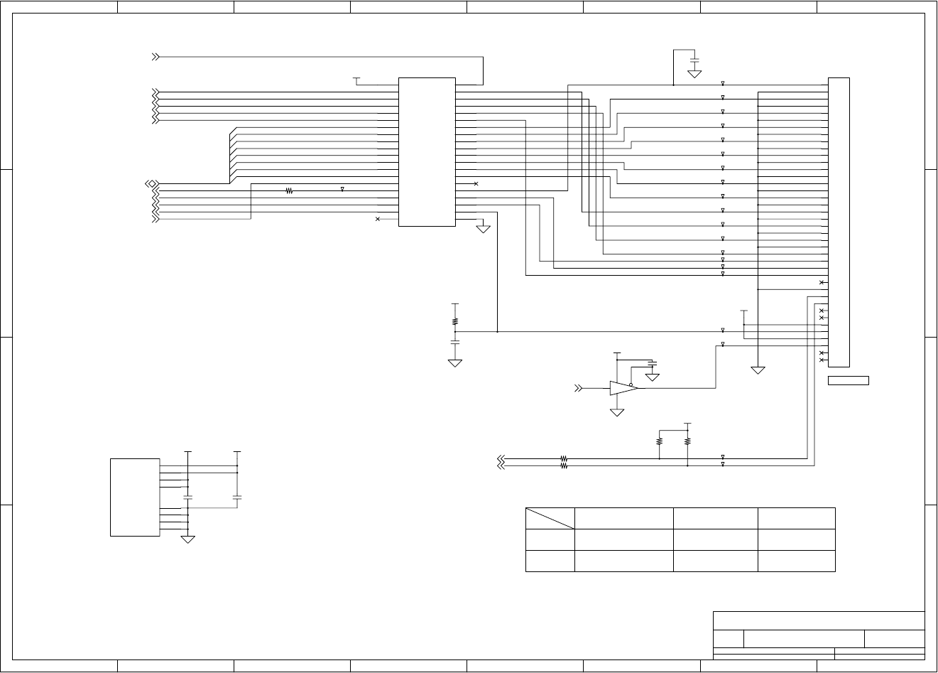
Chapter 6 Circuit Diagrams
CL-S700/CL-S703/CL-S700R 6-16
Circuit Diagram (Main PCB 13/15) [Centronics I/F]
1 2 3 4 5 678
A
B
C
D
8
76
54321
D
C
B
A
Title
Number RevisionSize
A4
Date: Sheet of
File: Drawn By:
A
MAIN PCB - CENTRONICS I/F
JN66701-0
(12/15)
NOT CONNECTED
LOW
NETWORK BD
LOW
HIGH
CENTRO CN
HIGHIETYP1
HIGH
HIGH
IETYP0
DAT6
DAT5
DAT7
xATFD-XT
DAT4
xACKNLG
BUSY
DAT0
DAT1
SLCT
DAT2
xSTROBE
DAT3
xRESET
PE
xFAULT
IEEE1284
xPRIME
xSLCT-IN
DATA[7:0]
DATA0
DATA1
DATA2
DATA3
DATA4
DATA5
DATA6
DATA7
VCC 7
VCC 18
VCC_CABLE 42
GND 39
GND 34
GND 15
GND 10
VCC_CABLE 31
HD
1
A9
2
A10
3
A11
4
A12
5
A13
6
A1
8
A2
9
A3
11
A4
12
A5
13
A6
14
A7
16
A8
17
PLHIN
19
A14
20
A15
21
A16
22
A17
23
HLH
24
DIR 48
Y9 47
Y10 46
Y11 45
Y12 44
Y13 43
B1 41
B2 40
B3 38
B4 37
B5 36
B6 35
B7 33
B8 32
PLH 30
C14 29
C15 28
C16 27
C17 26
HLHIN 25
1
2
3
4
5
6
7
8
9
10
20
11
19
12
18
13
17
14
16
15
21
22
23
24
25
26
27
28
29
30
31
32
33
34
35
36
37
38
39
40
2 4
53
1
T335
T323
R175 3.3k
R174 3.3k
T332
T324
C105
0.1u/16
C104
10u/10
C101
12p/50
R171
3.3k
T325
T327
T334
U22B
74LVX161284
R170 100
U22A
74LVX161284
J17
PS-40PE-D4T1
U23
*74AHCT1G125
R172
22k
C102
*12p/50
T328
T337
T329
T318
T333
T319
C103
*0.1u/16
T326
T336
T330
T320
T338
R173
22k
T321
T331
T322
V3R3
V3R3
V3R3
V5R0
V5R0
V3R3
V3R3
-GRESET2,6,8
OBDIR6
xACKNLG6
BUSY6
PE6
SLCT6
xFAULT6
PLH6
DATA[7:0]6
IETYP06
IETYP16
xSTROBE6
xATFD-XT6
xPRIME6
xSLCT-IN6
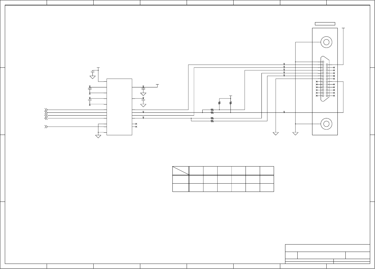
Chapter 6 Circuit Diagrams
6-17 CL-S700/CL-S703/CL-S700R
Circuit Diagram (Main PCB 14/15) [Serial I/F]
1 2 3 4 5 678
A
B
C
D
8
76
54321
D
C
B
A
Title
Number RevisionSize
A4
Date: Sheet of
File: Drawn By:
A
MAIN PCB - SERIAL I/F
JN66701-0
(14/15)
R178 R179
LDSR0
RXD0
TXD0
LDTR0
0
R176
DTR
NARTS NA
NANA
RS232C I/F
00
0
R177 R180 R181
NA
NA
0
0
DTR
RTS
TXD
RXD
CTS
DSR
25
24
23
22
20
21
19
1
2
3
416
15
14
13
12
11
10
9
8
7
6
5
18
17
C1+
2
R1I 16
EN
1
V+ 3
C1-
4
R1O
15
V- 7
T2O 8
R2I 9
R2O
10
NC1 11
T2I
12 T1I
13
NC2 14
C2+
5
C2-
6
Vcc
19
T1O 17
GND
18
SHDN
20
T344
C107
1u/B16
R177
*3.3k
J18
DBR40-251F100
U24
ZT3222LEEY
T345
C110
1u/B16
T341
T346
T347
T343
FG1
Lock_pin
T351
R178 *0
T350
C108
1u/B16
T348
R176
3.3k
C106
1u/B16
R181 0
T339
T340
T342
R180 *0
T352
R179 0
FG2
Lock_pin
C109
1u/B16
T349
V5R4
V3R3
V5R4
V5R0
TXD02
LDTR02
RESET2,10
LDSR02
PLDRXDI6
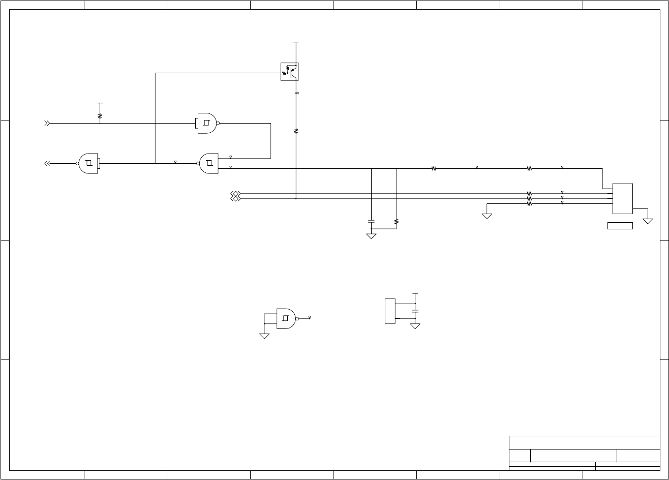
Chapter 6 Circuit Diagrams
CL-S700/CL-S703/CL-S700R 6-18
Circuit Diagram (Main PCB 15/15) [USB I/F]
1 2 3 4 5 678
A
B
C
D
8
76
54321
D
C
B
A
Title
Number RevisionSize
A4
Date: Sheet of
File: Drawn By:
A
MAIN PCB - USB I/F
JN66701-0
(15/15)
USB I/F
USBVCC
USBLGND
DM
DP
1
2
3
4
5
V14
G7
C111
33p/50
T361
R188 0/2012
T358
R184 20k/1%
R183
1.5k
U25D
74VHC132
12
13
11
Q17
DTA114EM
10k
10k
J19
DUSB-BRA42
VCC
DM
DP
GND
SG
U25A
74VHC132
1
2
3T359
T360
T354
R185 0/2012
U25E
74VHC132
T356
T353
U25C
74VHC132
9
10
8
R187 24/2012
T363
R182
1k
U25B
74VHC132
4
5
6
T357
C112
0.1u/16
R189
30k/1%
T362
R186 24/2012
V3R3
V3R3
V3R3
USBON2
UDM2
UDP2
UBINTP2
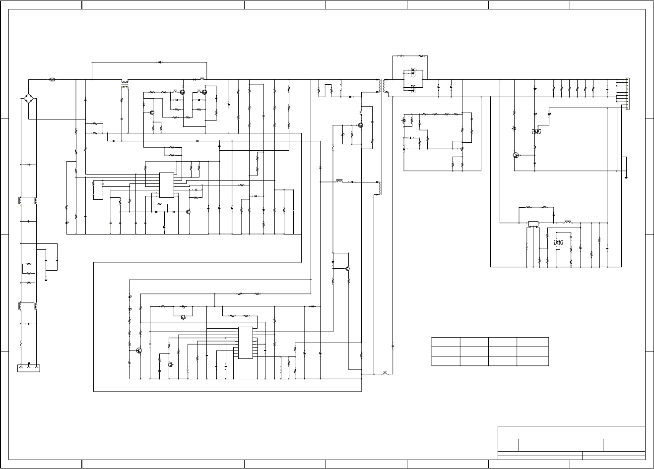
Chapter 6 Circuit Diagrams
6-19 CL-S700/CL-S703/CL-S700R
Circuit Diagram (Power Supply PCB (100/240V))
1 2 3 4 5 678
A
B
C
D
8
76
54321
D
C
B
A
Title
Number RevisionSize
A4
Date: Sheet of
File: Drawn By:
A
POWER SUPPLY
JN6601-0
LA
5
3 TB
+5V
GND
GND
GND
TLP421
(TOSHIBA)
2SK3569/Q
(TOSHIBA)
2SA1162Y
(TOSHIBA)
CRH01
(TOSHIBA)
1SS355 (ROHM)
6
2
T1
TA
1SS301
(TOSHIBA)
YG802C04R (F.E)
MIN
GND
HR24-122 (KOURINGIKEN)
HR24-122 (KOURINGIKEN)
UDZS18B(ROHM)
CRS04
(TOSHIBA)
2SA1244-Y/Q (TOSHIBA)
2SK2613 (TOSHIBA)
RN1402 (TOSHIBA)
CRH01 (TOSHIBA)
LB
CRH01
(TOSHIBA)
FSU10A60
(NIHON INTER) CZ62301-G
0.04A
315W
12.8A
+24V
+24V
+24V
RN1402 (TOSHIBA)
1SS355
(ROHM)
TLP421
(TOSHIBA)
UDZS30B(ROHM)
(F.E)
1SS355
(ROHM)
2SK3569/Q
(TOSHIBA)
1SS355
(ROHM)
CRS04
(TOSHIBA)
0.10A
TYP
1.50A
MAX
+24V
GND(+5V)
D10XB60H
(SHINDENGEN)
2SA1244-Y/Q
(TOSHIBA)
CRH01
(TOSHIBA)
(MITSUBISHI)
1NU41
(TOSHIBA)
FCF16A40
(NIHON INTER)
128W
+24V 5.00A
AC100V/240V(85-264V)
1DL42A
(TOSHIBA)
CRH01
(TOSHIBA)
FCF16A40
(NIHON INTER)
SI-8050J
(SANKEN)
+ 5V 1.50A
2W 27k
R65
2W 27k
R64
2W 27k
R66
-
R81
1/4W 100k
R58
250V T10AH
F1
L
FG
N
INPUT
CN1 L1
1.2mH
275V 0.68uF
C1
1/4W 100k
R1
FG
22k
R53
470
R51
0.1uF
C6
1/8W 68k
R85
35V 56uF
C47
Q7
10k-10k
PI1:A
470
R52
0.1uF
C9
10k
R56
100k
R50
ZD6
120B
1/8W 68k
R83
100
R68
1/8W 68k
R77 ZD5
120B
1
C
2
VOUT
9
DET
3
E
14
CT
5
NC
12
CF
11
T-ON
10
F/B
13
T-OFF
8
OVP
20
VCC
4
VF
18
CLM-
6
NC
7
ON/OFF
15
NC
16
NC
17
GND
19
CLM+
IC3
M51995AFP
10k
R74
0.22uF
C32
470pF
C13
33k
R55
0.22uF
C29
0.022uF
C30
0.022uF
C33
0.22uF
C34
1/4W 47
R78
ZD4
30B
PI2:A
1/4W 47
R79
33k
R80
2W 100k
R67
2W 100k
R71
1/4W 33k
R75
ZD7
18B
L2
1.2mH
1/4W 100k
R2
250V 1500pF
C3
250V 1500pF
C2
275V 0.33uF
C4
Z1
680V
600V 10A
DS1
R3
10
5W 0.1
R15
1/4W 10
R24
1/4W 10
R20
1/4W 220k
R96
1/4W 47
R29
1/4W 47
R28
D15
80V 0.1A
1/8W 220k
R90
-
R57
33k
R45
0.1uF
C21
0.01uF
C49
2.2k
R41
470pF
C19
0.1uF
C45
0.047uF
C23
1uF
C38
D14
80V 0.1A
1/4W 220k
R93
5.6k
R46
220pF
C17
100pF
C20
1/4W 220k
R95
1/8W 27
R12
D10
200V 1A
100k
R59
8
OUT
4
OVP
6
VIN-
5
VFB
14
SYNC
7
GND
9
VC
10
VCC
16
IDET
11
CS
13
REF
15
CT
12
ON/OFF
1
IFB
2
IIN-
3
VDET
IC1
FA5502
35V 150uF
C36
47uF
C27
0.22uF
C43
50V 0.15A
Q12
820k
R84 D17
80V 0.1A
3.9k
R87
22k
R89
3.9k
R82
18k
R72
1/8W 0
R92
1/8W 0
R91
330k
R86
0.15uF
C46
D11
200V 1A
D16
200V 1A
-
R97
D18
80V 0.1A
22k
R88
-
R94
1/4W 2.2
R25
600V 10A
Q2
1/4W 10k
R26
D5
40V 1A
D4
-
L3
CZ59303-G
1/4W 27
R63
0.1uF
C37
630V 1.0uF
C7
5W 0.1
R14
1/4W 2.2
R23
1/4W 2.2
R21
50V 5A
Q1
D3
40V 1A
70BB
FB1
600V 10A
Q3
450V 220uF
C25
2kV 220pF
C22
1/4W 10k
R30
1/4W 2.2
R27
D6
40V 1A
2W 47
R32
70BB
FB3
DS2
600V 10A
70BB
FB2
1/4W 270k
R38
1/4W 270k
R42
630V 0.047uF
C40
1/4W 270k
R39
1/4W 270k
R40
-
R69
1/4W 270k
R43
1/4W 270k
R44
-
R70
250V 1500pF
C35
1/4W 82
R76
-
C41
47
R73
56uF
C39
5W 0.1
R62
70BB
FB5
D13
200V 1A
1/4W 100
R60
1/4W 4.7
R61
PI1
PI2:B
1k
R209
1000V 8A
Q6
27k
R206
1/4W 10k
R49
IC200
MM1431ANR
50V 5A
Q8
D7
40V 1A
0.01uF
C26
ZD3
30B
D12
200V 1A
L4
10uH
125
TF1
D9
200V 1A
2W 68
R54
27k
R207
0
R203
-
C204
-
R202
3.3k
R208
VR200
500
500V 220pF
C200
PI1
PI1:B
630V 0.01uF
C28
2W 47k
R47
2W 47k
R48
D8
1000V 1A
2kV 100pF
C31
70BB
FB4
1/4W 470
R205
DS204
400V 16A
1/4W 470
R212
1k
R201
0.01uF
C205
1/4W 0
R217 1/4W 470
R204
DS200
400V 16A
35V 6800uF
C202
35V 6800uF
C203
0.033uF
C206
2W 47
R200
DA200
80V 0.1A
L104
100uH
0
R213
DS202
40V 10A
-
R216
0.022uF
C215
-
R214
3
4
5
12
Vin SWo
GND
S.S Vos
IC102
1/4W 10
R219
2200pF
C211
1/4W 10
R220
1/4W 220
R240
2200pF
C213
1/4W 220
R239
1/4W 10
R218
35V 1000uF
C217
1/4W 10
R215
0.1uF
C225
1/8W 470
R211
0.1uF
C207
Q200
10k-10k
FG
ZD203
15B
1/4W 10k
R210
ZD202
5.1B
ZD200
15B
1/4W 10k
R224
1/4W 10k
R225
1/4W 10k
R236
1/4W 10k
R234
1/4W 10k
R233
1/4W 10k
R235
0.47uF
C229
10
7
8
4
5
2
1
3
6
9
CN200
Notes:
1. Part whose constant is shown as "-" is not mounted.
2. Unless otherwise specified, wattage of resistor is 1/10W
and work voltage of capacitor is 50V.
3. Specification of this power supply is as follows.
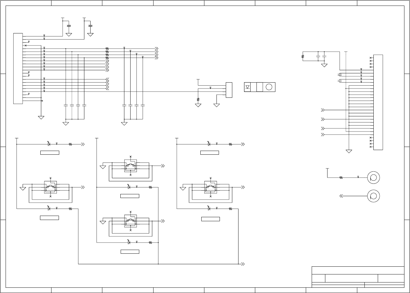
Chapter 6 Circuit Diagrams
CL-S700/CL-S703/CL-S700R 6-20
Circuit Diagram (Ope-pane PCB)
1 2 3 4 5 678
A
B
C
D
8
76
54321
D
C
B
A
Title
Number RevisionSize
A4
Date: Sheet of
File: Drawn By:
A
OPE-PANE PCB
JN66704-0
POWER
PAUSE
FEED
MENU
ERROR
STOP
VB1-
VB0-
BM0
VB0+
VOUT
NC
NC
NC
NC
Anode
Catiode
D7
D6
D5
D4
D3/SDA
D2
D1
D0/SCK
WR1
WR0
CD
RST
/CS
NC
NC
NC
NC
VDD
VSS
BM1
VB1+
1
23
4
A1 A3
B1 B2
A2 A4
B3
B4
1
2
3
4
A1 A3
B1 B2
A2 A4
B3
B4
1
2
3
4
5
6
7
10
9
8
11
12
13
14
15
16
17
18
19
20
21
22
23
24
25
26
27
28
29
30
A1 A3
B1 B2
A2 A4
B3
B4
A1 A3
B1 B2
A2 A4
B3
B4
1
2
3
4
5
6
7
8
9
10
20
11
19
12
18
13
17
14
16
15
21
22
C401
47u/16
+
D406
332MG
T434
C407 *0.1u/50
C411 *0.1u/50
T409
T432
SW401
EVPADC04K
T412
PAD401
R412
180/2012
R401 1k/1608
C410 *0.1u/50
C404
0.1u/50
T425
T437
T401
C412 *0.1u/50
PAD402
T418
R406
180/2012
T435
R402 1k/1608
T403
J403
B4B-PH-K-S
SW404
EVPADC04K
D402
310DT
D404
332MG
T411
T426
R413
180/2012
R409 16/1608
T436
J402
30FLH-SM1-TB
R408
180/2012
C413 *0.1u/50
T428
T421
T433
T413
T431
T423
T430
T404
R403 1k/1608
C408 *0.1u/50
T424
R407
180/2012
D401
310MT
R411
180/2012
C402
47u/16
+
D405
332MG
SW402
EVPADC04K
T422
C414 *0.1u/50
T429
T405
T406
T414
C405
1u/25
R405
1M
C403
0.1u/50
C406
1u/25
SW403
EVPADC04K
T419
T402
T408
T416
R404 1k/1608
T427
C409 *0.1u/50
R410
180/2012
T415
T420
T410
T417
D403
332MG
J401
22FMN-BMT-A-TF
T407
V5R0 V3R3
V5R0 V5R0 V5R0
V5R0
V3R3
V5R0
SW1
SW2
SW3
SW4
LCD_SDI
CS_LCD
LCD_SCK
LCD_CD
LED1
LED2
LED3
LED4
LCD_SDI
LCD_SCK
CS_LCD
LCD_CD
LED3
SW1
SW2
SW4
SW3
LED1 LED2
LED4
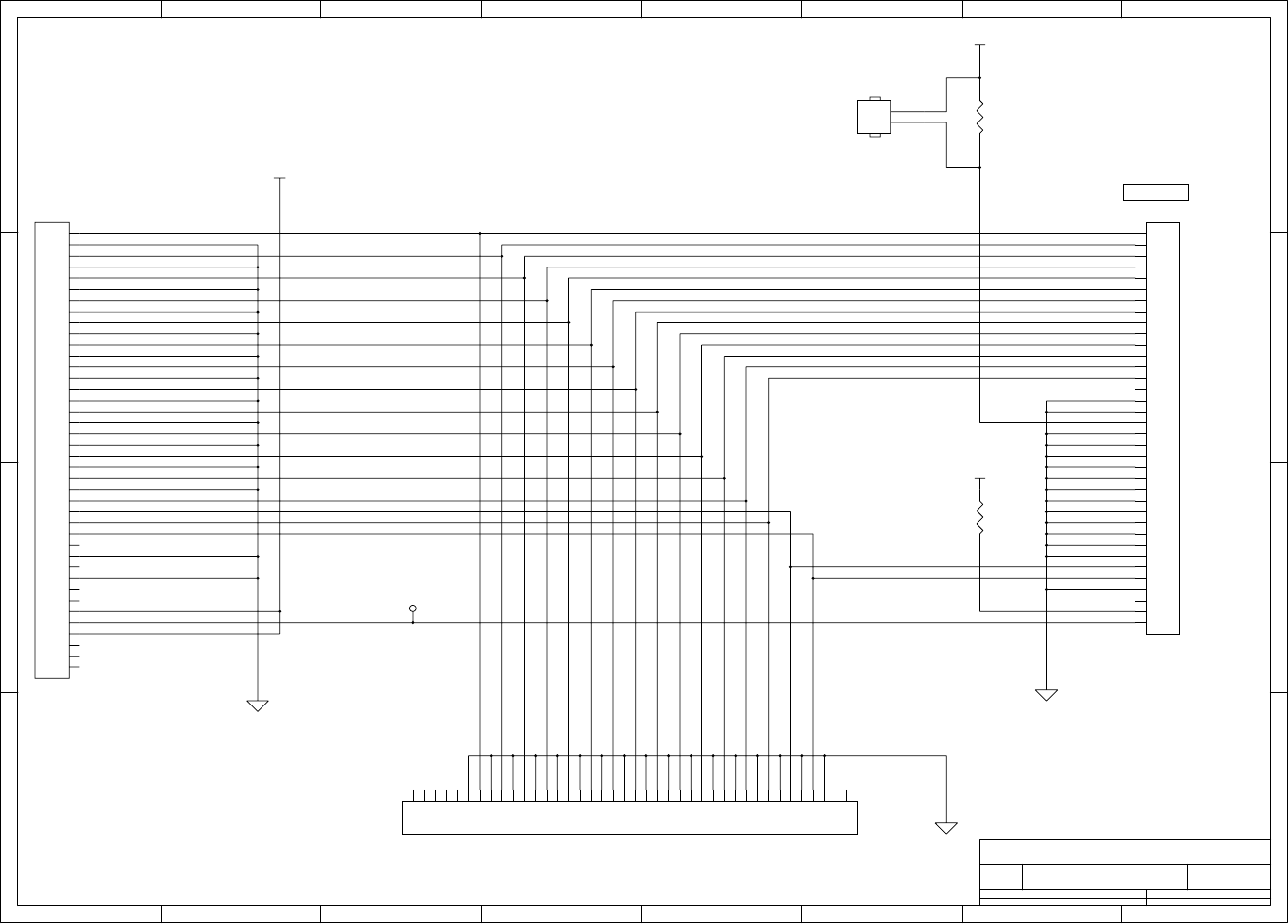
Chapter 6 Circuit Diagrams
6-21 CL-S700/CL-S703/CL-S700R
Circuit Diagram (Centronics PCB)
1 2 3 4 5 678
A
B
C
D
8
76
54321
D
C
B
A
Title
Number RevisionSize
A4
Date: Sheet of
File: Drawn By:
A
CENTRO PCB / CENTRONICS I/F CIRCUIT
JM66825-1
CN101
PS-40PE-D4T1-B1
R102
1k(NA)
CN102
57RE-40360-830B(D29)
CN103 PS-40PE-D4T1-B1
J101
RE-H022TD-1130
T101
R101
1k
V5R0
V5R0
V5R0
1
2
3
4
5
6
7
8
9
10
11
12
13
14
15
16
17
18
19
20
21
22
23
24
25
26
27
28
29
30
31
32
33
34
35
36
37
38
39
40
1
2
3
4
5
6
7
8
9
10
11
12
13
14
15
16
17
18
19
20
21
22
23
24
25
26
27
28
29
30
31
32
33
34
35
36
1
2
3
4
5
6
7
8
9
10
11
12
13
14
15
16
17
18
19
20
21
22
23
24
25
26
27
28
29
30
31
32
33
34
35
36
37
38
39
40
1
2
DATA6
xFAULT
xPRIME
DATA4
IEEE1284
xATFD-XT
PE
DATA7
DATA5
DATA3
xSTROBE
DATA2
SLCT
DATA1
BUSY
xACKNLG
xSLCT-IN
xFAULT
S.GND
BUSY
S.GND
S.GND
F.GND
S.GND
xSLCT-IN
DATA4
S.GND
xSTROBE
DATA3
S.GND
xACKNLG
PE
S.GND
DATA5
xATFD-XT
S.GND
VCC/PLH
SLCT
S.GND
DATA6
S.GND
xPRIME
S.GND
S.GND
S.GND
DATA2
S.GND
DATA0
FUSE
DATA1
DATA7
xSTROBE
DATA0
DATA1
BUSY
xACKNLG
DATA4
PE
DATA7
DATA0
DATA5
DATA3
DATA6
DATA2
SLCT
xPRIME
xATFD-XT
xFAULT
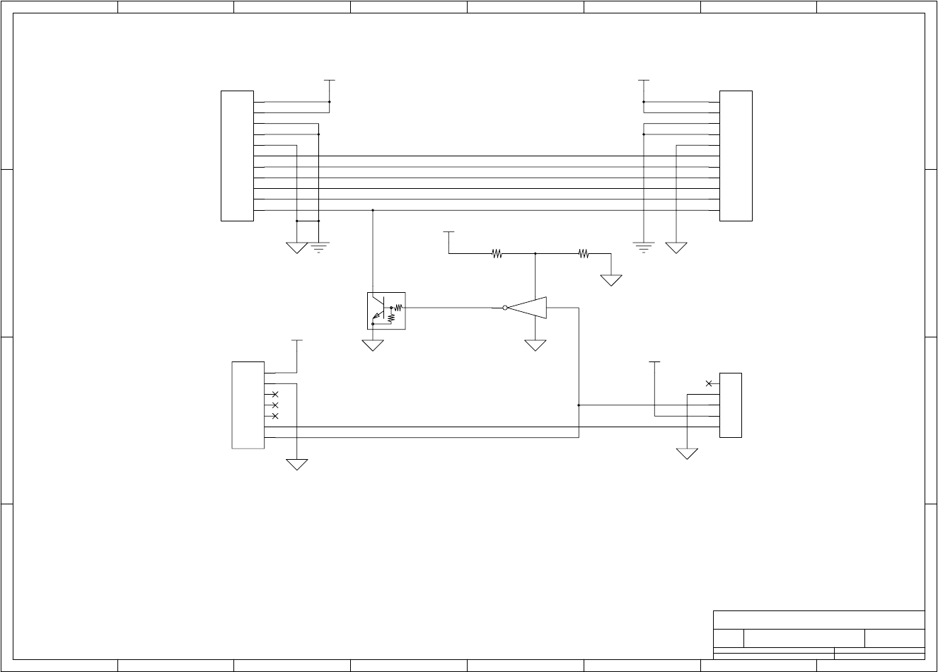
Chapter 6 Circuit Diagrams
CL-S700/CL-S703/CL-S700R 6-22
Circuit Diagram (Connect PCB) (CL-S700/CL-S703)
1 2 3 4 5 678
A
B
C
D
8
76
54321
D
C
B
A
Title
Number RevisionSize
A4
Date: Sheet of
File: Drawn By:
A
SA, CONNECT PCB
JN66725-0
DCMTR0
DCMTR1
HPSENS0
HPSENS1
MTTH
CPRTYP0
MTREF
MTENC
OPN
PEELSENS
CPRTYP1
24
53
1
2
3
4
5
1
2
3
4
5
6
7
8
9
10
11
1
2
3
4
5
6
7
8
9
10
11
1
2
3
4
5
6
7
R801 1.5k R802 3.3k
U801
TC7SH04
V
G
N
Q801
DTC114EM
10k
10k
J804
B5B-PH-K-S
J801
B11B-PASK
J802
B11B-EH
J803
B7B-PASK
V24R0 V24R0
V5R0
V5R0
V5R0
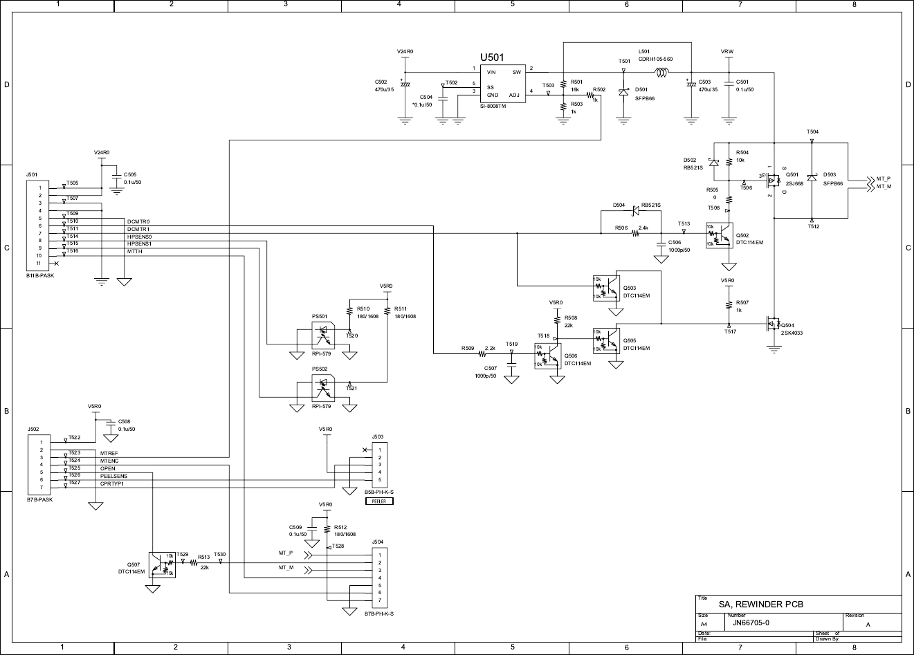
Chapter 6 Circuit Diagrams
6-23 CL-S700/CL-S703/CL-S700R
Circuit Diagram (Rewinder PCB) (CL-S700R)

Appendices
CL-S700/CL-S703/CL-S700R
APPENDICES
Appendices
CL-S700/CL-S703/CL-S700R AP-2
Appendices
Table of Contents
A. External Size Diagram .................................................................................................... AP-3
B. Mounting Diagrams......................................................................................................... AP-4
B-1. Main PCB ........................................................................................................... AP-4
B-2. Power Supply PCB (100V/220V) ....................................................................... AP-5
B-3. Ope-pane PCB................................................................................................... AP-7
B-4. Centro PCB ........................................................................................................ AP-7
B-5. Connect PCB (CL-S700/CL-S703).....................................................................AP-8
B-6. Rewinder PCB (CL-S700R) ............................................................................... AP-8
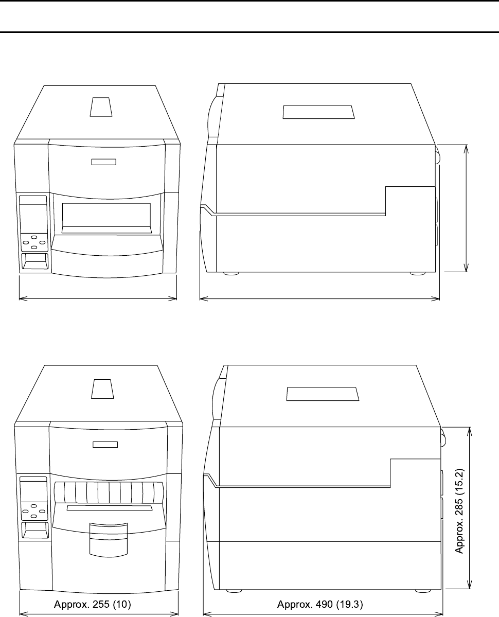
Appendices
A. External Size Diagram
AP-3 CL-S700/CL-S703/CL-S700R
A. External Size Diagram
Unit: mm (inch)
[CL-S700/CL-S703]
[CL-S700R]
Approx. 255 (10) Approx. 490 (19.3)
Approx. 265 (10.4)
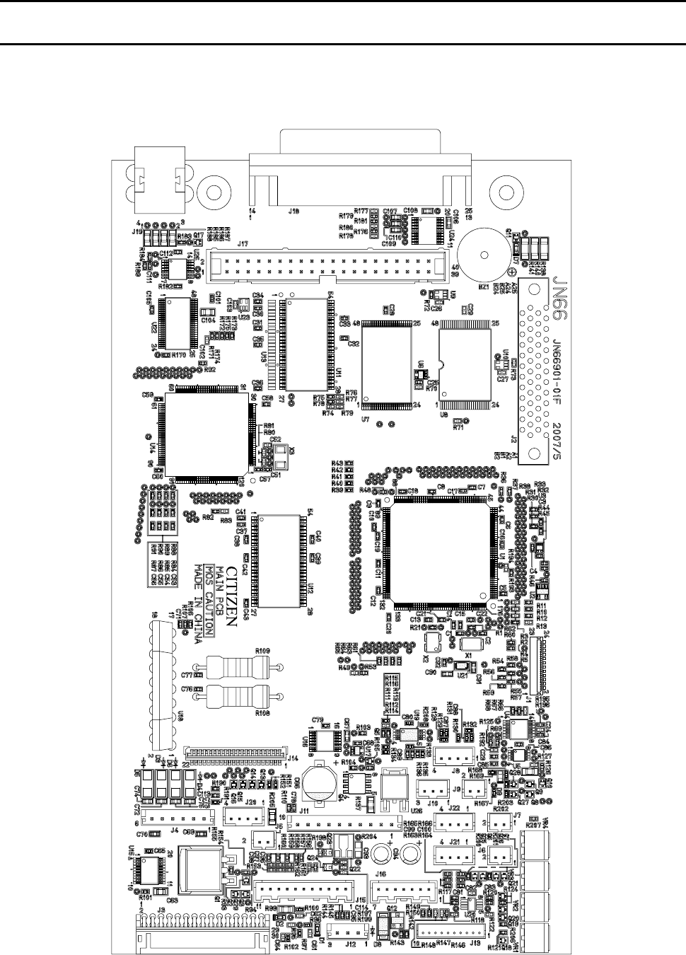
Appendices
B. Mounting Diagrams
CL-S700/CL-S703/CL-S700R AP-4
B. Mounting Diagrams
B-1. Main PCB
[Main PCB - Parts side]
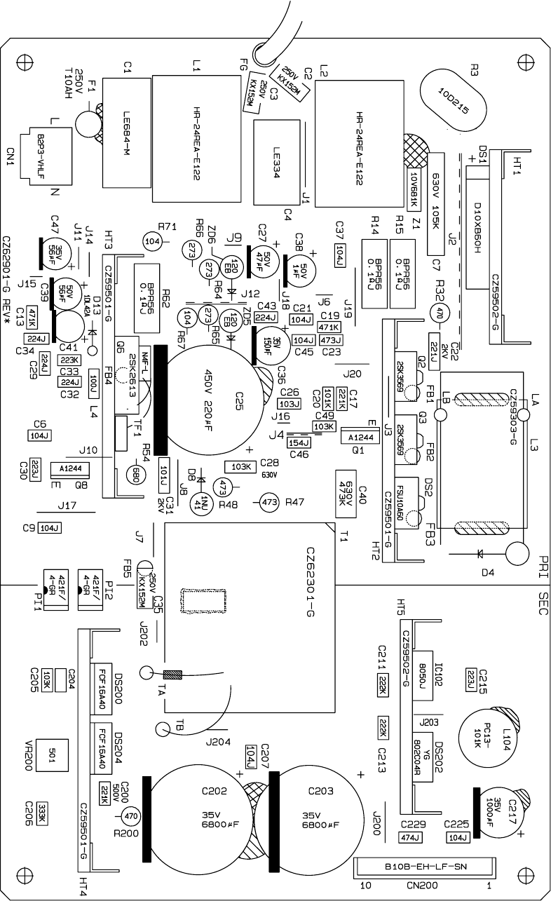
Appendices
B. Mounting Diagrams
AP-5 CL-S700/CL-S703/CL-S700R
B-2. Power Supply PCB (100V/220V)
[Power Supply PCB - Parts side]
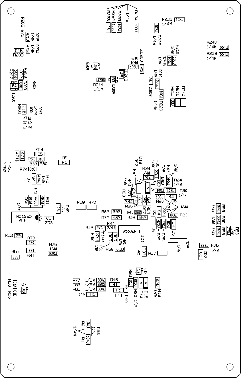
Appendices
B. Mounting Diagrams
CL-S700/CL-S703/CL-S700R AP-6
[Power Supply PCB - Solder side]
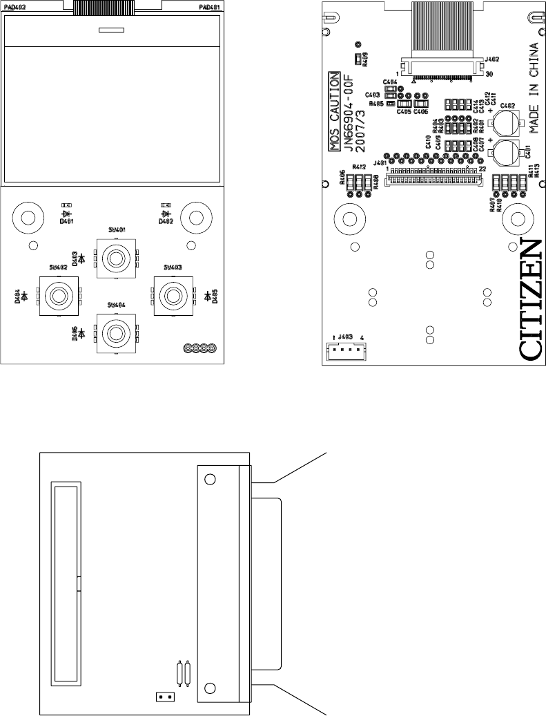
Appendices
B. Mounting Diagrams
AP-7 CL-S700/CL-S703/CL-S700R
CN101
B-3. Ope-pane PCB
[Parts side] [Solder side]
B-4. Centro PCB
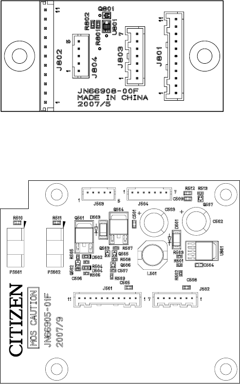
Appendices
B. Mounting Diagrams
CL-S700/CL-S703/CL-S700R AP-8
B-5. Connect PCB (CL-S700/CL-S703)
B-6. Rewinder PCB (CL-S700R)

363 Van Ness Way, Suite 404
Torrance, CA 90501. USA
Tel: (310) 781-1460
Fax:(310) 781-9152
http://www.citizen-systems.com
Mettinger Strasse 11 Park House, 643-651 Staines Road
D-73728, Esslingen Feltham, Middlesex, TW14 8PA
Germany United Kingdom
Tel: +49 (0) 711 3906 420 Tel: +44 (0) 20 8893 1900
Fax:+49 (0) 711 3906 405 Fax:+44 (0) 20 8893 0080
http://www.citizen-europe.com
6-1-12, Tanashi-cho, Nishi-Tokyo-shi
Tokyo, 188-8511. Japan
Tel: +81 (0) 42 468 4608
Fax:+81 (0) 42 468 4996
http://www.citizen-systems.co.jp
エラー
!
指定したスタイルは使われていません。
エラー
!
参照元が見つかりません。
CL-S700/CL-S703/CL-S700R 1-ii
