City Hong Teng Yu Da Electronic Technology JDY-08 Bluetooth module User Manual
Shenzhen City Hong Teng Yu Da Electronic Technology Co. Ltd. Bluetooth module
User Manual

JDY-08
User Manual
Product Name: Bluetooth module
Brand: HTYD
Model: JDY-08
Manufacture: Shenzhen City Hong Teng Yu Da Electronic
Technology Co. Ltd.

JDY-08
Product Overview
The JDY-08 Bluetooth module is based on Bluetooth 4 standard, the working frequency is
2.4GHZ, the modulation mode is GFSK, the maximum transmission power of 0dB,
maximum transmission distance of 60 meters, using TICC2541 chip, support the user
through the AT command to change the device name, service UUID, transmitting power,
pairing password and other commands, convenient and flexible.
Function Brief
1: WeChat pass (support AirSync protocol, applied to WeChat H5 or manufacturer server
communication)
2:APP transparent transmission (support for Android and IOS data transmission)
3:iBeacon mode (support for WeChat shake up protocol and apple iBeacon protocol)
4: sensor mode (temperature, humidity and many other sensors, data acquisition
applications)
5: host pass mode (application data transmission between modules, host and slave
communication)
6: host Viewer Mode (Applied sensors, indoor positioning)
7:PWM mode (used in motor speed control, LED light brightness adjustment)
8:IO mode (used for mobile control relay or LED lights out)
9: indoor location applications (the application of data acquisition iBeacon to achieve
range positioning)
10:RTC function
11: supports LED light products (with 26 fixed modes, with custom mode, and panel
mode), and how it works
Optional jump, gradient, strobe.
12: support massage products, the default comes with massage methods, there are warm
massage, comfortable massage, pulse massage and so on
13: support iBeacon probe function
14: support RTC timing function

JDY-08
Electrical characteristics
Working model
state
Electric current
Slave
transmission
model
Connection / connection
/ standby
0.8mA/300uA/1uA
Slave broadcast
mode
IBeacon sensor
Connection / connection
/ standby
0.5mA/300uA/1uA
Host
transmission
model
Connection / connection
/ standby
8mA/8.5mA/1uA
Host observer
mode
(sensor)
Connection / connection
/ standby
9mA
The test power supply voltage is 3.3V
technical parameter
1: through the transmission, the serial port to write data, support hundreds of bytes of
writing (such as 512 bytes)
Serial port Potter 115200, the serial port supports 712 bytes (Byte) write
57600, the serial port supports 712 byte (Byte) write
38400, the serial port supports 800 byte (Byte) write
19200, support 900 byte serial (Byte) write
9600, the serial port supports 3K byte (Byte) writing
2: effective communication distance 15 to 30 meters
3: working temperature -40 ~ +80 degrees centigrade
JDY-08
Low power settings hint (enter sleep AT+SLEEP, wake on the falling edge of the
PWRC pin)
Broadcast mode power saving scheme
Broadcast shallow sleep: serial port to send AT+SLEEP or AT+SLEEP1, the current
can be set to lower through broadcast intervals
Deep sleep: serial send AT+SLEEP2, at this time the current in a few uA, this mode
is not broadcast
Connection mode power saving scheme
1: connection state needs low power consumption, the P01 pin is held low, AT
AT+SLEEP or AT+SLEEP1 command module into MCU to make sleep, when the
data will be P01 pulled high by the falling edge of the PWRC pin wake Bluetooth, so
you can ensure that the case in connection to the Bluetooth power consumption is
very low,
2: of course, you can also let the Bluetooth module and the user's MCU has been
sleeping, through the Bluetooth module to wake up the user's MCU, this way to do
more than 1 of the way to save power.
3: to reduce power consumption by setting the connection interval, this mode is
configured to save power by 1 and 2
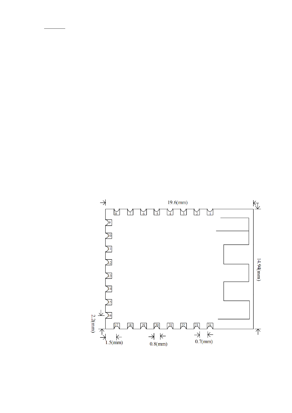
Dimensionaldrawing
JDY-08
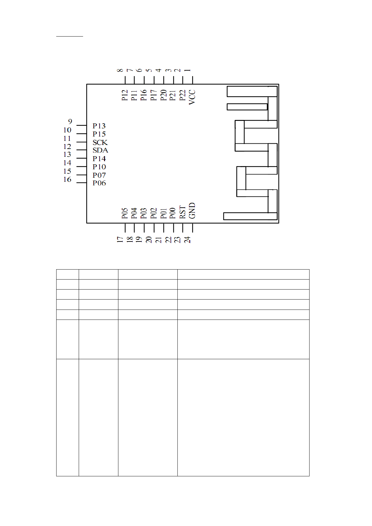
Pin definition
Pin function description
Pin
Definition
function
description
1
VCC
Power Supply
The power supply is 3V or 3.3 volts
2
P22
3
P21
4
P20
5
P17
RTC timed
interrupt
RTC is high when it is turned on and the
time is low
Only when the timing value is clear will
it become high level
6
P16
Connection status
pin
The connection is high and is not
connected to the low level (valid)
This is the default setting
The user can set the connection status of
the P16 pin or the pulse output and data
delay through the AT command
The user needs to wake up the user MCU
via the P16 pin, and then send the data
back to the user MCU, which can be set by
the AT command
For more details, please read the
AT+REVERSE instruction function

JDY-08
7
P11
PWM2
The PWM2 output pin can be controlled by
the APP
8
P12
IO1
The output IO1 pin can be controlled level
via the APP
9
P13
IO2
The output IO2 pin can be controlled level
via the APP
10
P15
IO3
The output IO3 pin can be controlled level
via the APP
11
SCK
The JDY-08D version supports IIC
Communications
12
SDA
The JDY-08D version supports IIC
Communications
13
P14
IO4
The output IO4 pin can be controlled level
via the APP
14
P10
PWM1
The PWM1 output pin can be controlled by
the APP
15
P07
PWM3
The PWM3 output pin can be controlled by
the APP
16
P06
PWM4
The PWM4 output pin can be controlled by
the APP
17
P05
Broadcast status
pin
Broadcast flashing, often bright after the
connection (master-slave effective)
18
P04
19
P03
TXD
Serial output, the level is TTL level
20
P02
RXD
Serial port, level is TTL level
21
P01
AT instruction
control pin
Low level AT mode with default high
level
This pin does not need to be sent AT if it
is connected
When the AT instruction in the state of
the connection request, the P01
pin is held low, in AT mode, the
user can then send the AT
command, to pass through the
data when P01 will maintain a
high level, immediately into
transmission mode
Is it necessary to send P01 to the low
level if the AT command is not
connected?
Answer: No, the module is AT mode in
an unconnected state. The user
does not need to send the AT
command in the case of

JDY-08
connection, and the P01 pin is
left unconnected
22
P00
PWRC
Not connected, sleep, press, wake up,
After connection, wake up and press
disconnect
After connection, press awake when
asleep
23
RST
reset
Hardware reset pin
24
GND
Power ground
AT Instruction
sequ
ence
instructions
Effect
Mast
er /
slav
e
Working
model
default
1
AT+RST
reset
M/S
-
2
AT+BOUD
Serial baud setting
M/S
-
115200
3
AT+HOSTEN
Master-slave setting
M/S
-
From the
machine
4
AT+HOST
Read host status
M
-
5
AT+DISC
Disconnect
M/S
-
6
AT+ADVEN
Turn on the radio
S
-
open
7
AT+ADVIN
Broadcast interval
S
-
100ms
8
AT+NEIN
Connection interval
S
-
10ms
9
AT+POWR
Transmitted power
S
-
0db
10
AT+NAME
Broadcast name
S
-
JDY-08
11
AT+MAC
Read the MAC address
M/S
-
12
AT+STRUUID
Set iBeacon UUID (string
type UUID)
S
iBeacon
WeChat
UUID
13
AT+HEXUUID
Set iBeacon UUID (sixteen
hexadecimal type UUID)
S
iBeacon
WeChat
UUID
14
AT+MAJOR
Set iBeacon Major (string
type Major)
S
iBeacon
10
15
AT+MINOR
Set iBeacon Minor (string
type Minor)
S
iBeacon
7
16
AT+VER
Read version number
M/S
-
JDY-08-2.1
17
AT+VID
Manufacturer identification
number
S
iBeacon
sensor
88
18
AT+TEMP
(used for factory
identification)
S
iBeacon
sensor
0

JDY-08
19
AT+HUMID
Temperature setting
S
iBeacon
sensor
0
20
AT+ISCEN
Temperature setting
S
-
Close
21
AT+PASS
Sets whether to open a
password connection
S
-
123456
22
AT+SVRUUID
Change service UUID
M/S
-
FFE0
23
AT+CHRUUID
Change features UUID
M/S
-
FFE1
24
AT+SCAN
Host scanner slave
M
Host
transmis
sion
25
AT+RSLV
Read slave scan to slave
MAC
M
Host
transmis
sion
26
AT+CONNET
Connect scan to slave MAC
M
Host
transmis
sion
27
AT+BAND
Bind slave MAC
M
-
28
AT+GETDCD
The number of machines to
read from the host scan
M
-
29
AT+GETSTAT
Find the working state of the
module
M/S
-
30
AT+PWMFRE
Set PWM frequency
M/S
-
1000HZ
31
AT+PWMOPE
N
Open PWM
M/S
-
Close
32
AT+PWM1PU
S
Set the pulse width of
PWM1
M/S
-
50%
33
AT+PWM2PU
S
Set the pulse width of
PWM2
M/S
-
50%
34
AT+PWM3PU
S
Set the pulse width of
PWM3
M/S
-
50%
35
AT+PWM4PU
S
Set the pulse width of
PWM4
M/S
-
50%
36
AT+WXSVR
WeChat H5 and server
communication settings
S
WeChat
H5
37
AT+RTCFLSH
RTC refresh time (seconds)
M/S
-
38
AT+RTCDAT
E
RTC time reading and
writing
M/S
-
39
AT+RTCOPE
N
RTC switch
M/S
-
40
AT+RESTOR
E
Restore factory
configuration
M/S
-
41
AT+STARTEN
Does the boot wake up?
M/S
Wake
mode

JDY-08
42
AT+SLEEP
Sleep mode
M/S
43
AT+KBYTE
Transfer speed setting
M/S
1K bytes/s
44
AT+REVERS
E
P1_6 level and wake-up
MCU delay
M/S
1
45
AT+CLSS
Set device type
S
passthro
ugh
A0
46
AT+RTCALA
M
RTC read and write timing
value
M/S
47
AT+ALAMEN
RTC timing switch
M/S
close
48
AT+RSSI
RSSI value
S
49
AT+PIO
AT command control IO
M/S
50
AT+PARITY
Serial parity bit setting
Parity bit
51
AT+WXINEN
WeChat automatic and
manual test mode selection
S
Manual
mode
AT instruction specification
Special instructions: JDY-08 module, serial AT command does not need to add
terminator \r\n
Soft reset
Instruction
response
parameter
AT+RST, +OK, none
AT+RST, +OK, none
AT+RST, +OK, none
Settings / queries - P1_6 level mode (0-1 is only pin level change, and 2-6 is delayed
transmission)
Instruction
response
parameter
AT+REVERSE<Param>
+OK
Param: (0-6)
0: connect low, not connected high
level
1: connect high level, not connected
low level
(0-1) principal and subordinate are
effective
When the parameter is set from 2 to
6, the P16 pin is usually
High level, delay XXms, recovery of
high level and the output data from
the APP, this method is not suitable
for large data transmission, only
suitable for small data transmission,
AT+REVERSE
+REVERSE:<Para
m>

JDY-08
mainly for Bluetooth MCU MCU wake
up, usually in sleep, data APP,
Bluetooth wakes up the user MCU,
then output XXms delay data to the
MCU, this will ensure that the APP
sends data and can wake up the
MCU, MCU and APP (2-6 can
receive data from the machine)
2: delayed 50ms output data
3: delayed 100ms output data
4: delayed 200ms output data
5: delayed 400ms output data
6: delayed 1000ms output data
Default: 1
Special instructions: when set to 0-1, the connection pin P16 will have a change in the
connection state
Set 2-6, P16 is usually high, there is connection or APP data down, the module generates
a drop edge delay pulse, low level delay time, please according to the above delay
parameters through the AT instruction adjustment
This instruction is very useful for low power consumption products require a higher, and
this ensures that users of MCU can be normal in a sleep state, when the data is coming to
wake the user's MCU, and then the output data to the user MCU
Settings / queries - device type
Instruction
response
parameter
AT+CLSS<Param>
+OK
Param (00-FF)
IBeacon mode type
0XE0:iBeacon type
0XE1: temperature sensor
0XE2: humidity sensor
0XE3: temperature and
humidity sensor
0XE4: fragrant machine
0XE5: intelligent water meter
and meter reading
0XE6: voltage sensor
0XE0: current sensor
0XE0: weight scale
0XE0:PM2.5 sensor
Transparent mode type
0XA0: transmission 0
(Universal)
AT+ CLSS
+ CLSS:<Param>

JDY-08
0XA1: transmission 1 (serial
output status)
0XA2: pass through 2
(Security)
0XA5: massage stick (AV
stick)
0XA6: massage bra
0XA7: massage chair
0XA8: tattoo machine
0XB1:LED light band
0XB2:LED bulb bulb
0XB3:LED candle light
0XC1: one way switch
controller
0XC2: dual switch controller
0XC3: three way switch
controller
0XC4: four way switch
controller
0XD1: air purifier
0XD5: water dispenser
0XD6: Ordinary electronic
locks
0XD7: fingerprint electronic
lock
Default: pass through 0
AT+ CLSS description:
Where is the difference between AT+ CLSS and AT+HOSTEN (module work mode
instructions)?
Answer: the AT+ CLSS device type is the device type of the AT+HOSTEN
Example 1: the user wants to configure the LED ribbon type to send AT instructions as
follows
1:AT+HOSTEN0 / / configured transparent transmission mode
2: AT+ CLSSB1 / / LED configuration into the lamp type
3: send AT+RST / reset
You configure the LED device type through the 3 steps above
Example 2: the user wants to configure the iBeacon type to send the AT instruction as
follows
1:AT+HOSTEN3 / / configured transparent transmission mode
2: AT+ CLSSE0 / / iBeacon type configuration
3: send AT+RST / reset
You configure the iBeacon device type through the 3 steps above

JDY-08
transparent
transmissi
on
type
Serial output status
APP features
FFE2
function
PWRCPress
function
Con
nect
To
brea
k off
Boot
print
awaken
sleep
AT+CLSSA
0
NO
NO
NO
response
Disconne
ct
awaken
AT+CLSSA
1
YES
YES
YES
response
Nonfuncti
onal
awaken
AT+CLSSA
2
NO
NO
NO
No response
Nonfuncti
onal
awaken
Description: the factory default for AT+CLSSA0 type, this function is to pass through
common functions, such as the user of the product safety requirements are very
high, beware of other people use APP to modify the parameters can modify the
module (broadcast, broadcast interval, interval connection etc.), users can consider
using the AT+CLSSA2 model, some model of APP configuration parameters (no
response radio, radio, etc.), the connection interval interval of these parameters
can only be modified by AT instruction.
If the user MCU pins not much data, do not want to use MCU to determine the Bluetooth
connection status, you can consider using the AT+CLSSA1 mode, in this mode,
when a Bluetooth connected or disconnected from the serial output module, status
information to the user MCU

JDY-08
FCC Statement
This device complies with part 15 of the FCC Rules. Operation is subject to the
following two conditions: (1) This device may not cause harmful interference,
and (2) this device must accept any interference received, including
interference that may cause undesired operation.
Any Changes or modifications not expressly approved by the party responsible
for compliance could void the user's authority to operate the equipment.
The modular can be installed or integrated in mobile or fix devices only. This
modular cannot be installed in any portable device.
FCC Radiation Exposure Statement
This modular complies with FCC RF radiation exposure limits set forth for an
uncontrolled environment. This transmitter must not be co-located or operating
in conjunction with any other antenna or transmitter. This modular must be
installed and operated with a minimum distance of 20 cm between the radiator
and user body.
If the FCC identification number is not visible when the module is installed
inside another device, then the outside of the device into which the module is
installed must also display a label referring to the enclosed module. This
exterior label can use wording such as the following: “Contains Transmitter
Module FCC ID: 2AM2YJDY-08 Or ContainsFCC ID: 2AM2YJDY-08”
When the module is installed inside another device, the user manual of the
host must contain below warning statements;
1. This device complies with Part 15 of the FCC Rules. Operation is subject to
the following two conditions:
(1) This device may not cause harmful interference.
(2) This device must accept any interference received, including interference
that may cause undesired operation.
2. Changes or modifications not expressly approved by the party responsible
for compliance could void the user's authority to operate the equipment.
The devices must be installed and used in strict accordance with the
manufacturer's instructions as described in the user documentation that comes
with the product.
Any company of the host device which install this modular with limit modular
approval should perform the test of radiated emissionand spurious emission
according to FCC part 15C : 15.247 and 15.209 requirement,Only if the test
result comply with FCC part 15C : 15.247 and 15.209 requirement,then the
host can be sold legally.