Clarity A Division of Plantronics C120 TV Listener User Manual
Clarity, A Division of Plantronics, Inc. TV Listener
User Manual
E
N
G
L
I
S
H
E
S
P
A
~
N
O
L
C120TM User Guide
Clarity®
TV Listener
CONTENTS
Parts checklist.................................................................................... 3
Quick Reference Guide .................................................................. 4
Features................................................................................................ 5
Clarity Power Control ................................................................. 5
Telephone ring notification .............................................................5
Public IR address usage................................................................ 5
Setup Guidelines
C120 Transmitter .......................................................................... 6
C120 Headset................................................................................ 9
Troubleshooting..............................................................................12
Safety Information.........................................................................13
Technical Specifications ..............................................................14
Regulatory Compliance ...............................................................15
3
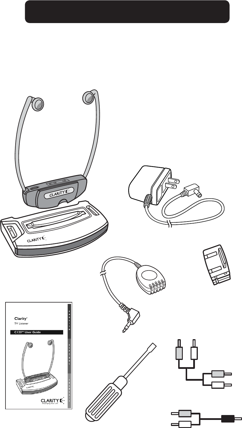
PARTS CHECKLIST
AC wall charger
Microphone
Rechargeable
battery
User Guide
C120 Transmitter
C120 Headset
RCA stereo cable
RCA mono cable
Flathead
screwdriver
1. Headset Receiver
2. Transmitter Base
3. TV Microphone
4. Rechargeable Battery
5. Power Supply
6. RCA Cable (dual red and white plugs)
7. RCA - 3.5mm Cable
8. Flathead Screwdriver
9. User Guide
4
LR
L (WHITE)
R (RED)
STEREO RCA JACKS
TV BACK VIEW
Alternate Mono cable (provided)
(if TV only has one sound jack)
STEREO / MONO
STEREO / MONO
L/MONO
TV C120
L
R
DC12V LINE PHONE
STEREO MONO MIC
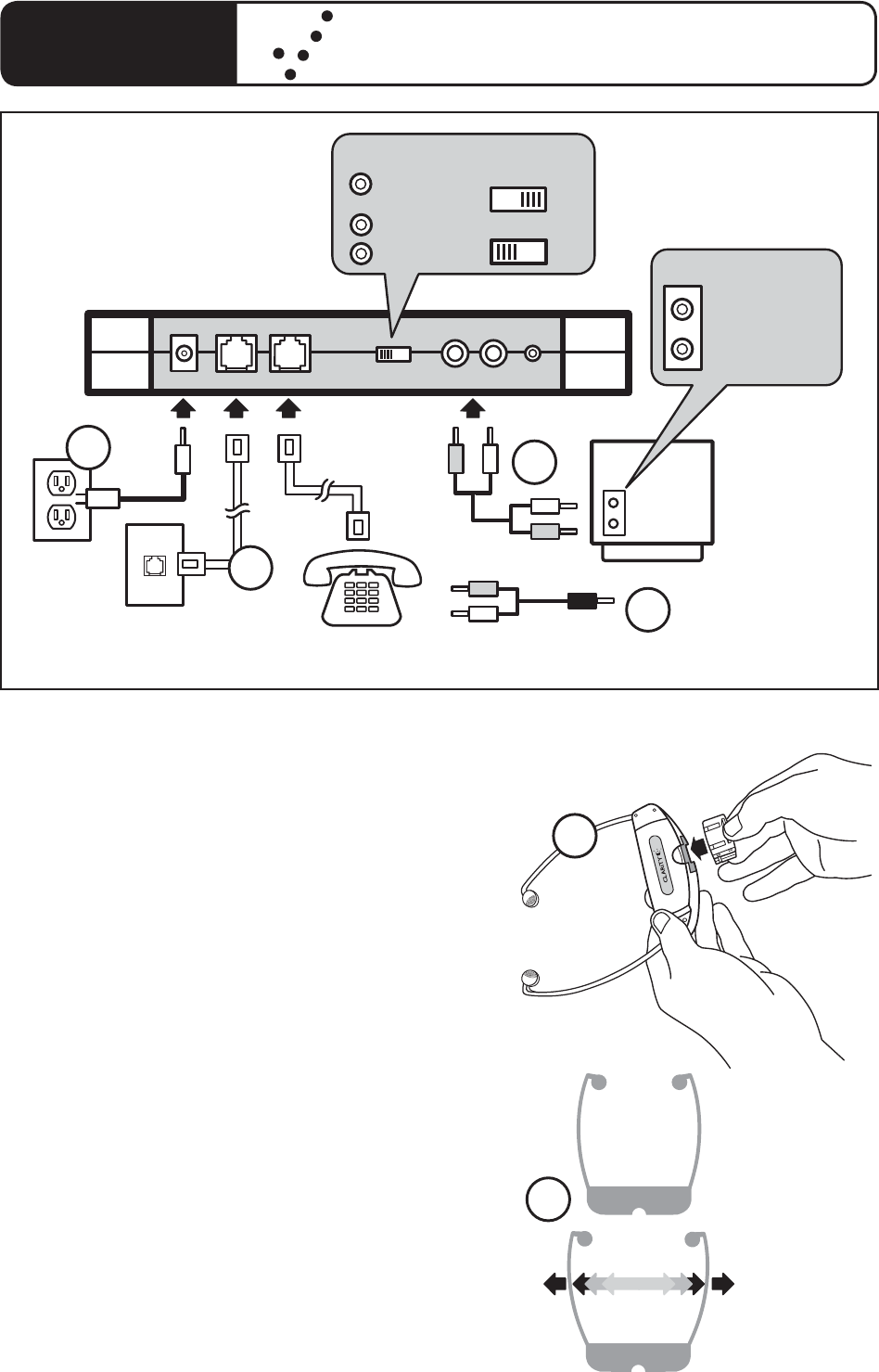
1. Plug in power adapter
2. Connect RCA (red and white) jacks.
A. If the television has only one RCA
jack, the “STERO/MONO” switch
on the base should be set to “MONO”.
B. If there are two RCA jacks, base
should be set to “STEREO”.
3. For ring notification, connect
telephone line from wall to “LINE”
and connect line from “PHONE”
to telephone.
4. After battery has charged overnight,
place in headset.
5. To POWER-ON headset, place on
head. As the arms are spread apart,
the unit powers on.
QUICK START GUIDELINES
OFF
ON
4
5
2A
2B
3
1
C120TM Quick Reference Guide
5
C120TM OPERATION
Thank you for purchasing this new and exciting product from Clarity. The
C120™ provides an enjoyable television viewing experience for people who
have a hard time hearing the television.
The C120™ uses wireless infrared technology to send signals from the tele-
vision or other device to the headset receiver. This means that this product
can be used without the hassle or mess of cords.
The C120™ can be used with HDTV, Satellite, Digital, Plasma, LCD and
standard televisions. It can also be used to listen to other audio equipment,
such as a stereo. The use of the product eliminates the need to turn the
volume to extremely loud levels, without disturbing other viewers or others
in the area.
The C120™ not only can be used for enjoying at home, but can be used
outside the home in places like the movies, conventions, museum tours, and
sporting events (where a public infrared system is offered). Check with the
site administration to see if infrared service is available.
FEATURES
Clarity® Power ControlTM
The Clarity Power Control improves the quality of the incoming audio
signal from the television for a better listening and viewing experience. The
amplification of the television audio will be increased and the frequency band
from 2000 to 3000Hz will be specially enhanced to improve the clarity of
the television audio.
Telephone Ring Notification
This feature will notify the user of an incoming telephone call through the
C120™ Headset. An audible notification will be heard to notify the user that
the phone is ringing.
Public IR Address Usage
This feature allows the headset to be worn at public events where the
infrared system is offered to those with assisted listening devices. Examples
of these areas could be movies, churches and public speeches. Check with
the site administration to see if infrared service is available.
6
SETTING UP THE
C120™ TRANSMITTER
Important Setup Guidelines
The C120™ TV Listener transmitter may be
placed on top of a television or shelf. This
product uses infrared light. This type of signal
can be blocked by solid objects. Do not place
objects in between the transmitter base and
the headset receiver.
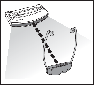
For the clearest signal, place the base at your
viewing eye level or above. As illustrated in
Fig.1, the clearest signal emitted from the
base is in a straight line, directly in front of
the base. The base must be clearly visible
from your television viewing position.
It is important to follow the above guidelines
to ensure communication between the base
and headset.
Sunlight can cause interference with the pro-
duct and cause problems such as buzz, static, or
hiss. As a result, this product cannot be placed
in direct sunlight or be used outdoors.
The headset will only receive the signal in the
same room where the base is located. The
maximum operating distance is approximately
38 feet, depending on environment.
Multiple headsets may be used with a single
base if they are set to the same frequency.
However, if more than one base is being used
at the same time, interference will occur.
C120TM OPERATION
FIG. 1
38 feet

7
C120TM OPERATION
CONNECTING THE TRANSMITTER
Power
First, connect the Power Supply into the DC12V
jack located on the back of the base. The DC12V
port is illustrated in Fig. 2. Then plug the Power
Supply into a wall outlet.
Audio
Next, using one of the Audio Cable supplied,
connect the base unit directly to the TV, VCR,
or other equipment output jacks. See different
connection options listed below.
Included in the package, there are two cords to
use for the incoming audio. One will have two
RCA jacks (red and white) on both ends. (Fig.
3) This can be used to connect with devices with
both Right and Left channel RCA jacks (TV’s,
VCR’s, etc). The other is a cord with two RCA
jacks (red and white) on one end and on the
other is a 3.5mm jack. (Fig. 4) A 3.5mm jack is
the size found on a pair of headphones. This can
be used to connect the C120™ to devices with
3.5mm ports, such as CD players, radios and
other small electronics. See Figures 6-9.
1. Stereo Mode:
(For Highest Sound Quality) This mode should
be used if the television (or other audio equip-
ment) has two RCA audio jacks (red and white).
See Figures 3 and 4.
Connect the RCA plugs from the speaker
output of the TV or VCR into both the left
and right RCA jacks on the base.
Next, select “Stereo” on the
Mono/Stereo switch.
DC12V
FIG. 2
FIG. 4
VCR
TV R
W
STEREO MONO
FIG. 3

8
C120TM OPERATION
2. Mono Mode:
This mode should be used if the television
(or other audio equipment) has only one audio
RCA or a 3.5mm jack.
This enables the C120™ to be used with
computers, CD players, stereos, mp3 players,
and other related products.
If the television, or other device, has only one
RCA port, connect the left (white) RCA plug
from the output into the left (white) RCA jack
of the base. The right (red) jack should remain
unplugged. See Figure 5.
If the television, or other device, has a 3.5mm
jack, use the cord with the RCA jacks on one
end and 3.5mm jack on the other. Plug the
3.5mm into the device and plug the RCA jacks
into the C120™ base. See Figures 6-9.
Next, select “Mono” on the Mono/Stereo
switch.
3. Microphone Mode:
Use this mode only if an RCA connection is not
available. For example, older televisions do not
have audio outputs. In this case, the micro-
phone should be used. Connect the supplied
microphone into the “Mic” jack on the back of
the base, as illustrated in Figure 10. Place the
microphone near the speaker of the television
or stereo.
Note: The microphone may pick up any sound
in the room, such as speech, the doorbell, or
the telephone. (Fig. 11)
MIC
FIG. 10
CD Player
FIG. 8
MP3
Player
FIG. 9
FIG. 5
TV
R
W
FIG. 6
STEREO MONO
3.5mm jack
TV
FIG. 7
Computer
FIG. 11
9
Telephone
The C120™ has the ability to produce an
audible indicator heard through the headset
when the telephone rings. The following
step is necessary if telephone ring notification
is desired.
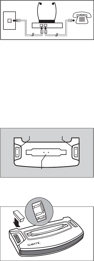
First, plug the telephone cord coming from
the wall into the jack on the rear of the base
labeled “LINE.” A phone cord can then be
connected from the jack labeled “PHONE”
on the rear of the base to a telephone. This
process is illustrated in Figure 12.
The C120™ allows you to use the same
phone wall outlet for both your phone and
C120™ TV Listener.
SETTING UP THE C120™ HEADSET
Installing the Batteries
The supplied battery is a NiNH battery.
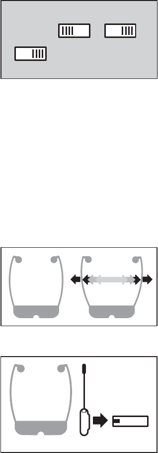
Install the supplied Rechargeable Battery
into the bottom of the headset. Once you
place the headset into the base, as illustrated
in Fig. 13, it begins to charge the battery.
The main Headset Battery Charger and both
backup batter chargers on the base have a
corresponding LED light on the front panel
that will light up when a dock is being used.
Backup batteries can be bought and placed
in the additional charging docks located on
the base. The charging docks are labeled
in Figure 14.
Having these extra batteries to switch in and
out will enable longer product usage without
having to wait for a battery to charge. When
the product is not in use, return the headset
to the base to recharge the battery.
C120TM OPERATION
FIG. 12
FIG. 14
Note: The battery is not
charged when it comes out of
the box. It must be charged
overnight before usage.
HEADSET CHARGER
BACKUP BATTERY CHARGERS
FIG. 13
10
The volume at which the product is set will
have an effect on battery life. At full volume,
the battery will last approximately four (4)
hours. Using lesser volumes will increase the
length of the charge. An indication that the
battery should be changed might be the sound
getting weak or noisy. The battery takes four
(4) hours to fully charge and can be charged
approximately five hundred (500) times before
it should be replaced.
Adjusting the Headset
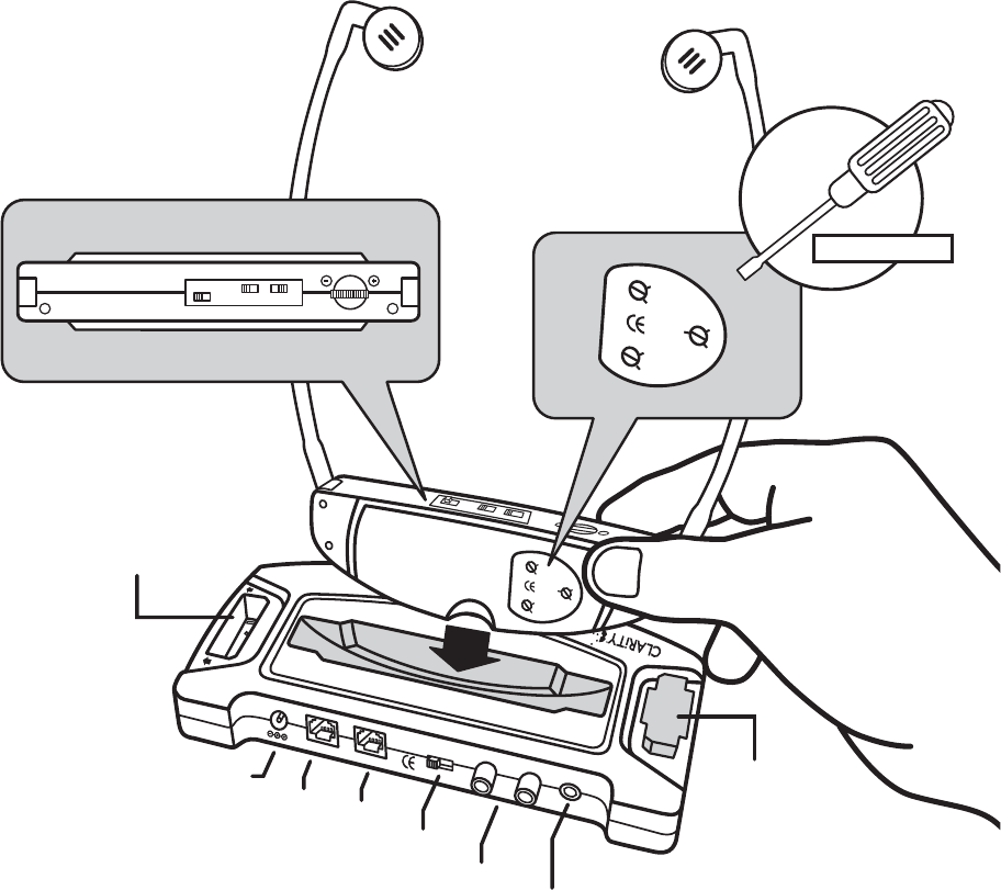
On the top of the headset (receiver) there is a
switch labeled “Home/Away.” (Fig. 15) When
using the headset to listen to the television with
the included base, set switch to “Home.” For
use with public infrared systems, set the switch
to “Away.”
There is a volume control wheel on the top
of the headset where the volume can be con-
trolled easily while watching television. Turn the
wheel in the direction of the “+” to increase
volume and towards the “-” to decrease the
volume. (See Fig. 18 on page 11)
When the headset arms are extended, the unit
automatically powers on, as illustrated in
Fig. 16. When the headset is removed from
the head and the arms go back into original
position, the unit will power down. If there is
no audio signal being detected by the C120™
for one and a half minutes, it will power down.
Note: The infrared sensor that communicates
with the transmitter base is on the front of the
headset and should be pointed directly at the
base, as illustrated in Figure 17.
C120TM OPERATION
2.3 MHz 95 kHz
AWAYHOME
FIG. 15
OFF ON
FIG. 16
Headset front
Base
FIG. 17
11
AUXILIARY HEADSET CONTROLS
Balance Control
This adjusts the volume balance between the Left and Right earphones.
A small screwdriver will be needed to adjust this control.
Tone Controls
There are two controls for tone, one for each earphone (left and right).
A small screwdriver will be needed to adjust these controls.
C120TM OPERATION
DC12V
LINE
PHONE
STEREO MONO
RL
MIC
Rechargeable
Battery
Secondary
battery charging
location
C120 Headset
C120 Transmitter
DC 12V
plug-in Line
Stereo/Mono
Switch Right/Left
Speaker
inputs
Microphone
plug-in
Phone
+
-
BAL
L
R
+
-
+
-
HOME
AWAY
R
HOME AWAY
L
+
-
BAL
L
R
+
-
+
-
FIG. 18
INCLUDED
12
If the C120™ is producing no sound:
1. Ensure that proper installation and setup procedures were followed by
reading the user guide carefully.
2. Check to see if all the equipment is turned on, including the television
or VCR.
3. Look over all the cord connections (power, audio from television etc.),
making sure none have become loose or disconnected.
4. Ensure that the line of sight from the transmitter base to the headset
receiver is clear.
5. Check the battery in the C120™ Headset to see if it is fully charged.
6. Check to see if the infrared sensor on the base is facing the headset and
make sure the headset sensor is facing the base.
7. If the microphone is being used, try either turning up the television or
repositioning the microphone.
If the sound produced by the C120™ has static or is noisy:
1. If while in one mode (Stereo/Mono), static is experienced, switch the base
to the other mode.
2. Check the level of direct sunlight in the room. Too much direct sunlight
can cause interference.
3. Make sure the base is at the same height or above the level of the headset
when being worn.
Still Not Working?
If, after going through this checklist, the C120™ is still not functioning
properly, call Clarity at 1-800-426-3738.
TROUBLESHOOTING
13
Hearing Safety
The C120™ is designed to be used as an assisted listening device. This pro-
duct is intended to amplify sounds to a high volume. This means that damage
to hearing ability is a possibility if used improperly. To prevent any possible
hearing damage, please observe the following guidelines.
1. Turn the volume all the way down on the headset before putting it on.
2. When adjusting the volume to a comfortable level, start at the minimum
volume level then slowly turn the volume up. This will ensure the volume is
set at the minimum volume level needed to hear.
Medical Device Safety
Before using C120™ TV Listener in the area of a pacemaker or other medical
device, please consult a physician or the manufacturer of the medical device.
This will help determine if this product can be used in conjunction with other
medical devices in the area.
SAFETY INFORMATION
14
C120™ TRANSMITTER INFORMATION
Dimensions: 7 1/16”L x 3 5/8”W x 1 1/8”H, (17.9cm x 9.2cm x 2.8cm)
Weight: 5.2 oz (147g)
Power Supply: 100-240V, 50/60 Hz, 0.15 Amps
Charging Docks: Charges one (1) C120™ Headset and two (2) additional
batteries in the auxiliary docks.
Auto Off Power: Transmitter turns off after it has not detected audio signal
for 1.5 minutes.
Transmitting Frequency: 2.3MHz and 2.8MHz
Transmitter Range: Approx. 38ft
Microphone Input: 3.5mm jack for supplied TV Microphone.
Audio Cable Input: One (1) RCA cable, one (1) RCA to 3.5mm cable
C120™ HEADSET INFORMATION
Weight: 1.75 ounces (49g) without battery, 2.05 ounces (58g)
including battery
Frequency Received: 2.3MHz and 2.8MHz from transmitter, 95kHz from
public IR systems.
Controls: “Home/Away” switch to set the headset to proper frequency,
volume wheel, tone and balance controls.
Home: 2.3/2.8 MHz Away: 95 kHz
Amplified dB Level: 50dB, 125 dBSPL
Battery Type: Nickel Metal Hydride (NiMH), Rechargeable,
weight is 0.3 oz
Battery Life: Four (4) hour usage time, four (4) hour charge time, lasts
500 charges.
TECHNICAL SPECIFICATIONS
15
Part 68 of FCC Rules
Information
a) This equipment complies with
Part 68 of the FCC rules and the
requirements adopted by the ACTA.
On the bottom of this equipment is
a label that contains, among other
information, a product identifier in
the format US:AAAEQ##TXXXX.
If requested, this number must be
provided to the telephone company.
b) A plug and jack used to connect
this equipment to the premises
wiring and telephone network must
comply with the applicable FCC Part
68 rules and requirements adopted
by the ACTA. A compliant telephone
cord and modular plug, RJ11C
USOC, is provided with this product.
It is designed to be connected to a
compatible modular jack that is also
compliant. See installation instruc-
tions for details.
c) The REN is used to determine the
number of devices that may be con-
nected to a telephone line. Excessive
RENs on a telephone line may result
in the devices not ringing in response
to an incoming call. In most but not
all areas, the sum of RENs should
not exceed five (5.0). To be certain of
the number of devices that may be
connected to a line, as determined
by the total RENs, contact the local
telephone company. For products
approved after July 23, 2001, the
REN for this pro-duct is part of the
product identifier that has the format
US:AAAEQ##TXXXX.
The digits represented by ## are the
REN without a decimal point (e.g., 03
is a REN of 0.3). For earlier products,
the REN is separately shown on the
label.
d) If this telephone equipment causes
harm to the telephone network, the
telephone company will notify you in
advance that temporary discontinu-
ance of service may be required. But
if advance notice isn’t practical, the
telephone company will notify the
customer as soon as possible. Also,
you will be advised of your right to
file acomplaint with the FCC if you
believe it is necessary.
e) The telephone company may make
changes in its facilities, equipment,
operations or procedures that could
affect the operation of the equip-
ment. If this happens the telephone
company will provide advance notice
in order for you to make necessary
modifications to maintain uninter-
rupted service.
f) If trouble is experienced with this
telephone equipment, for repair or
warranty information, please con-
tact Clarity, 1-800-552-3368. If the
equipment is causing harm to the
telephone network, the telephone
company may request that you
disconnect the equipment until the
problem is resolved.
REGULATORY COMPLIANCE
16
g) This telephone equipment is not
intended to be repaired and it
contains no repairable parts. Open-
ing the equipment or any attempt
to perform repairs will void the
warranty. For service or repairs, call
1-800-552-3368.
h) Connection to party line service
is subject to state tariffs. Contact the
state public utility commission, public
service commission or corporation
commission for information.
i) If your home has specially wired
alarm equipment connected to the
telephone line, ensure the installation
of this telephone equipment does
not disable your alarm equipment. If
you have questions about what will
disable alarm equipment, consult
your telephone company or a quali-
fied installer.
j) This telephone equipment is hear-
ing aid compatible.
Customer-Owned Coin/Credit
Card Phones:
To comply with state tariffs, the
telephone company must be given
notification prior to connection. In
some states, the state public utility
commission, public service commis-
sion or corporation commission
must give prior approval
of connection.
Part 15 of FCC Rules
Information
This device complies with Part 15 of
the FCC Rules. Operation is subject
to the following two conditions: (1)
This device may not cause harmful
interference, and (2) this device must
accept any interference received,
including interference that may cause
undesired operation.
Your equipment has been tested and
found tocomply with the limits of a
Class B digital device, pursuant to
Part 15 of FCC rules. These limits
are designed to provide reasonable
protection against harmful interfer-
ence in residential installation.
This equipment generates, uses and
can radiate radio frequency energy
and, if not installed and used in
accordance with the instructions,
may cause harmful interference to
radio communications. However,
there is no guarantee that interfer-
ence will not occur in a particular
installation; if this equipment does
cause harmful interference to radio
or television reception, which can be
determined by turning the equipment
off and on, you are encouraged to try
to correct the interference by one of
the following measures:
1. Where it can be done safely,
reorient the receiving television
or radio antenna.
2. To the extent possible, relocate
the television, radio or other
REGULATORY COMPLIANCE
17
receiver with respect to the
telephone equipment. (This
increases the separation between
the telephone equipment and
the receiver.)
3. Connect the telephone equip-
ment into an outlet on a circuit
different from that to which the
television, radio, or other receiver
is connected.
4. Consult the dealer or an experi-
enced Radio/TV Technician
for help.
CAUTION: Changes or modifica-
tions not expressly approved by the
manufacturer responsible for compli-
ance could void the user’s authority
to operate the equipment.
Industry Canada Technical
Specifications
This product meets the
applicable Industry Canada
technical specifications.
Before installing this equipment, users
should ensure that it is permissible
to be connected to the facilities of
the local telecommunications com-
pany. The equipment must also be
installed using an acceptable method
of connection. In some cases, the
company’s inside wiring associated
with a single line individual service
may be extended by means of a
certified connector assembly (tele-
phone extension cord). The customer
should be aware that compliance
with the above conditions may not
prevent degradation of service in
some situations. Repairs to certified
equipment should be made by an
authorized Canadian maintenance
facility designated by the supplier.
Any repairs or alterations made by
the user to this equipment, or equip-
ment malfunctions, may give the
telecommunications company cause
to request the user to disconnect
the equipment.
Users should ensure for their own
protection that the electrical ground
connections of the power utility,
telephone lines and internal metallic
water pipe system, if present, are
connected together. This precaution
may be particularly important in
rural areas.
CAUTION: Users should not
attempt to make such connections
themselves, but should contact
the appropriate electrical inspec-
tion authority, or electrician, as
appropriate.
The Ringer Equivalence Number
is an indication of the maximum
number of terminals allowed to be
connected to a telephone interface.
The termination on an interface
may consist of any combination of
devices subject only to the require-
ment that the sum of the Ringer
Equivalence Numbers of all the
devices does not exceed five.
REGULATORY COMPLIANCE

18
(The term “IC:” before the certi-
fication/registration number only
signifies that the Industry Canada
technical specifications were met.)
The party responsible for
regulatory compliance:
Clarity, A Division of Plantronics, Inc.
4289 Bonny Oaks Drive, Suite 106
Chattanooga, TN 37406
Phone: 1-800-552-3368
Battery Disposal Information
The rechargeable batteries in
the C100™ need to be disposed
of properly and may need to be
recycled. Your local recycling
company can give instructions
on proper disposal methods.
CAUTION: Never dispose
of batteries in a fire.
REGULATORY COMPLIANCE

Clarity, a Division of Plantronics, Inc.
4289 Bonny Oaks Drive, Suite 106
Chattanooga, TN 37406
1-800-552-3368
www.clarityproducts.com
©2006 Clarity, a Division of Plantronics, Inc. All Rights Reserved.
Clarity, the amplification device, Clarity and the amplification device
combined, Amplifying Your Life, Clarity Power and C120 are
trademarks or registered trademarks of Plantronics, Inc.
Rev. A (9-06)