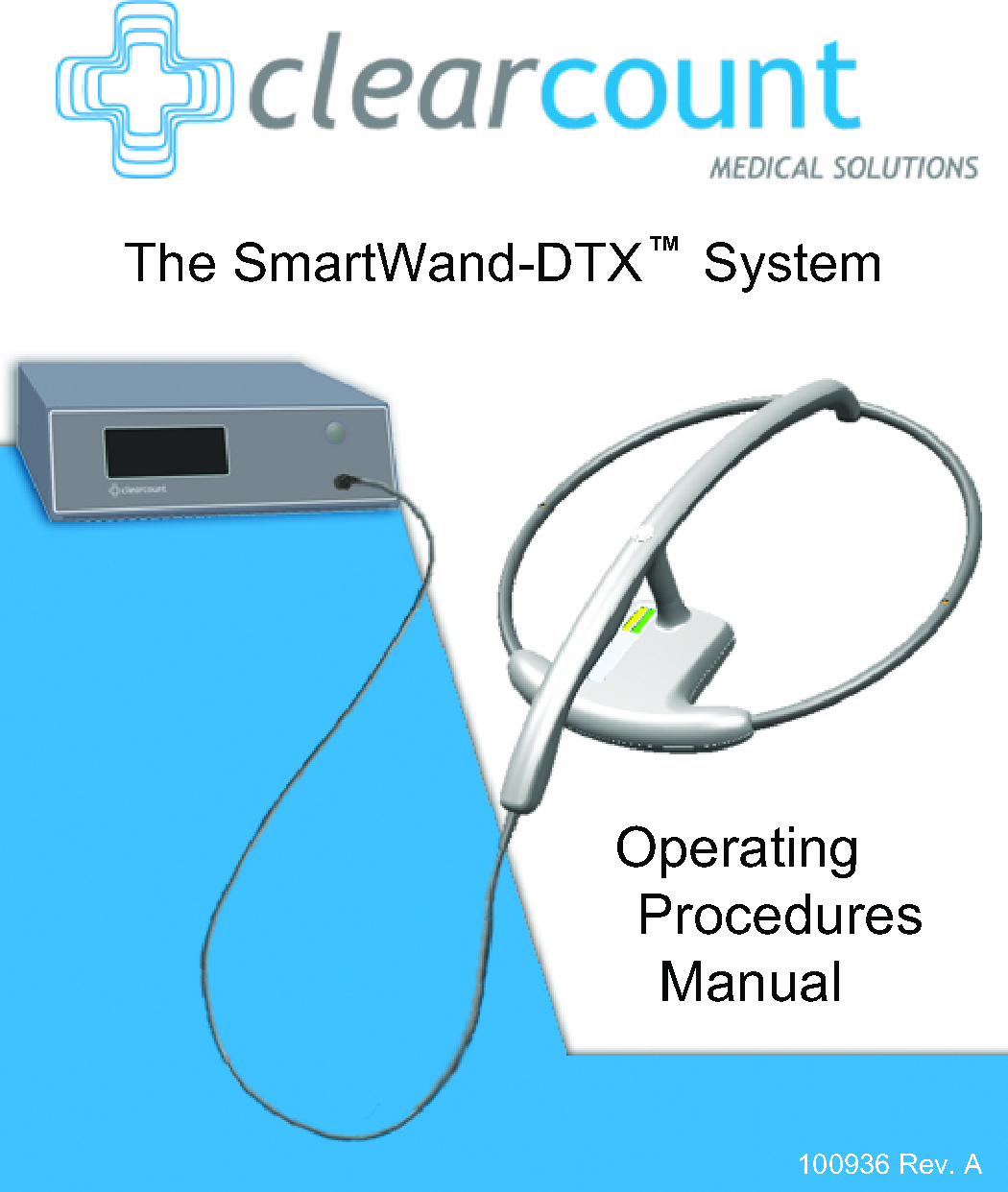
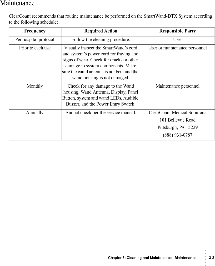
ClearCount Medical Solutions CCMS002 Detects & counts surgical items with RFID tags. User Manual SmartWand DTX manual

ClearCount Medical Solutions Inc. Detects & counts surgical items with RFID tags. SmartWand DTX manual

Contents

Users Manual

The SmartWand-DTX    SystemOperatingProceduresManualTM100936 Rev. A
i• • • •••• • • • • • PrefaceIndications for UseThe ClearCount Medical Solutions SmartWand-DTX™ System is indicated for use in counting and displaying the number of RFID-tagged surgical sponges, laparatomy sponges, and towels detected by the device and providing a non-invasive means of locating retained RFID-tagged surgical sponges, towels and other tagged items within a surgical site.WarningsThe following list of warnings applies to the SmartWand-DTX System:•Do not use the system in the presence of a flammable anesthetic mixture with air, or with oxygen or nitrous oxide.•For the system to function, use only ClearCount disposables.•Keep the SmartWand-DTX System outside of the sterile field, unless it is properly covered.•The sterility of disposables is guaranteed only for unopened, undamaged packages. Disposables are for single use only; do not re-use or re-sterilize disposables.•Do not cut or tear SmartSponge disposables, as the RFID tags might become separated.•Using the scanning wand without a sterile wand cover could contaminate the sterile field.•Disposables should not be left inside the patient's body for more than 24 hours.•Do not subject patients to an MRI with SmartSponge disposables still inside their body.•Tags may become damaged by surgical lasers. Do not apply a surgical laser directly to a tag. The loss of tag function may result.•Due to possible interference, the system should be separated by at least 1 meter from an active Electrosurgical Unit (ESU). The system should be checked for normal operation to ensure there is no interference present.•No part of the ClearCount SmartWand-DTX System is user serviceable. The system contains no user replaceable fuses. All Service is to be performed by trained personnel.
ii • • • •••Conventions Used Warning! A warning is a statement that identifies conditions or actions that could result in personal injury or loss of life.  Caution! A caution is a statement that identifies conditions or actions that could result in damage to the system.  Notes A note is an advisory comment or recommendation regarding practices or procedures.
Table of Contents• • • •••Preface ...............................................................................................................................................iChapter 1: System Description ......................................................................................................1-1System Components...................................................................................................1-2SmartWand Box............................................................................................1-2SmartWand....................................................................................................1-4SmartSponge Disposables.............................................................................1-5SmartWand Cover.........................................................................................1-7SmartTags .....................................................................................................1-8Chapter 2: Initial Setup and Operation ..........................................................................................2-1Initial Setup ................................................................................................................2-2Preparing the SmartWand-DTX System for Use..........................................2-2Placing the SmartTag....................................................................................2-3System Operation .......................................................................................................2-4Activating the System ...................................................................................2-4Using the SmartWand ...................................................................................2-5Deactivating the System ...............................................................................2-7Chapter 3: Cleaning and Maintenance...........................................................................................3-1Cleaning Instructions..................................................................................................3-2Maintenance ...............................................................................................................3-3Chapter 4: Troubleshooting ...........................................................................................................4-1General Troubleshooting............................................................................................4-2System Message .........................................................................................................4-4System Error...............................................................................................................4-5Appendix A: Technical Specifications .........................................................................................A-6SmartWand-DTX System Dimensions .....................................................................A-6Power Requirements .................................................................................................A-7EMC Considerations .................................................................................................A-8Device Label ...........................................................................................................A-13
1-1 • • • •••• • • • • • Chapter 1: System DescriptionThe SmartWand-DTX™ System is used in an operating room to detect and identify tagged surgical items for the purpose of preventing a retained foreign body. The system employs radio-frequency identification (RFID) technology to detect ClearCount SmartSponge® surgical sponges and towels. The system combines detection with the benefit of identification of surgical items (sponges, gauze, and towels) so detected items can be quickly identified. The system consists of a patient scanning wand and a wand box with a user-friendly display that provides detailed information about detected items. When an item is detected, the type and quantity will appear on-screen along with an audible notification. The SmartWand-DTX allows for a quick and easy scan of the patient to identify retained surgical items.This chapter includes a brief overview of the system and a detailed description of its components.
Chapter 1: System Description - System Components 1-2• • • •••System ComponentsSmartWand BoxThe SmartWand Box, shown in Figure 1-1, is the information and user hub of the SmartWand-DTX System. The Power Entry Switch is located on the back panel of the box, where the power cord is to be connected. The system provides visual cues to the user through the front mounted LCD Display where detected item information and system messages are shown. Two Bi-Color LEDs, also located on the front panel, will show system and detection statuses. Located inside: the Embedded Buzzer gives audible feedback to the user during detection and system alerts. Directly below the LEDs is the multifunction Panel Button; used to “Wake Up”, “Clear”, and “Sleep” the system. Right below the Panel Button is the Wand Connection where the cord to the SmartWand is connected.Figure 1-1     SmartWand BoxRight Bi-Color LEDLeft Bi-Color LEDLCD Display Panel ButtonWand ConnectionEmbedded BuzzerPower Entry SwitchONBACK
1-3 Chapter 1: System Description - System Components• • • •••Table 1-1 SmartWand BoxComponent DescriptionLeft Bi-Color LED Changes color with the wand’s detection status. Solid Blue - SmartTag detected Off - SmartTag/SmartSponge not yet detected Solid Amber - SmartSponge detectedRight Bi-Color LED Changes color with the system’s status.Off - System not poweredSolid Green - System poweredFlashing Green - Wand not connectedRed - System ErrorLCD Display Displays user information for system operation and item detection/identification.Top 3 lines are for sponge type and count, bottom line is for status and notification.Panel Button Multifunction button used to operate the System. Press - “Wake Up” (when LCD is OFF)Press - “Clear” (when LCD is ON)Press and Hold (3sec) - “Sleep” (system hibernate)Embedded Buzzer Alerts the user with an audible tone to system functions. Signals SmartTag and SmartSponge detection.Wand Connection Plug-in location for the SmartWand’s cord.Power Entry Switch Plug-in location for the power cord. Also the location of the switch to provide power to the system.
Chapter 1: System Description - System Components 1-4• • • •••SmartWandThe SmartWand, shown in Figure 1-2 is a patient scanning wand that houses an antenna for detecting ClearCount SmartSponges. The Handle of the wand is designed to ease the process of sterile sheathing while handing it into the sterile field by giving each person a place to grip. The Wand Cord exits the back end of the handle and connects to the Wand Connection on the SmartWand Box. Two LEDs mounted on the wand provide visual cues about the system’s operation. The Bi-Color LED displays detection status while the Single Color LED displays the wand’s power status. To scan the patient; hold the wand by its handle, pass it over the body maintaining a distance of 2 to 3 inches above, while completing five head to toe sweeps at a rate of 7 inches a second. Refer to Chapter 2 for the complete patient scanning procedure.Figure 1-2     SmartWandTable 1-2 SmartWandComponent DescriptionBi-Color LED Changes color with the wand’s detection status. Solid Blue - SmartTag detected Off - SmartTag/SmartSponge not yet detected Solid Amber - SmartSponge detectedSingle-Color LED Changes with the wand’s status.Solid Green - Wand attachedOff - Wand not attached or system errorSingle Color LEDBi-Color LEDHandleWand Cord
1-5 Chapter 1: System Description - System Components• • • •••SmartSponge DisposablesThe SmartWand-DTX System utilizes surgical sponges and towels that have been “tagged” with an RFID transponder. This RFID tag is similar in size to a Tic Tac® and does not contain a battery. Because each sponge contains a tag with unique identification, the SmartWand-DTX can quickly and accurately detect and identify each sponge.The SmartWand-DTX System relies on accessories for proper use. These accessories are described briefly in Table 1-3.Handle Used to hold the SmartWand while performing the patient scan.Wand Cord Provides power to the SmartWand while also allowing it to communicate with the SmartWand Box.Table 1-3 SmartSponge Disposables and AccessoriesAccessory DescriptionSurgical Kits A pre-packaged sterile kit of materials and equipment assembled for a specific surgery. Included are various banded packs of SmartSponges for use with the SmartWand-DTX System.Sterile Packages SmartSponges packaged by type for use with the SmartWand-DTX System that are not pre-packaged in Surgical Kits.Wand Cover A large, sterile, clear plastic sheath used to protect the sterile field when using the SmartWand. The sheath covers the wand and a portion of the wand cord.Table 1-2 SmartWand (Continued)Component Description
Chapter 1: System Description - System Components 1-6• • • •••Figure 1-3     Example of Sterile Surgical KitFigure 1-4     Example of Sterile Sponge PackagesSmartTag / SmartTag Special  An adhesive backed RFID tag applied between the sheets of the OR table prior to surgery, which assures that the SmartWand is operational. (SmartTag Special is only for use with carbon fiber top OR tables)Table 1-3 SmartSponge Disposables and Accessories (Continued)Accessory Description
1-7 Chapter 1: System Description - System Components• • • •••SmartWand CoverA sterile wand cover is used when scanning the patient with the SmartWand. The cover is passed into the sterile field and then applied to the SmartWand as it is handed in. Figure 1-5 shows the wand cover package.Figure 1-5     Sterile Cover for SmartWand (outside of surgical kit)
Chapter 1: System Description - System Components 1-8• • • •••SmartTagsSmartTags are passive RFID labels that have an adhesive backing (see Figure 1-6). Prior to surgery, a SmartTag is to be positioned under the surgical site between the bottom sheet and the draw sheet on the OR table. Chapter 2 describes the positioning of the SmartTag on the OR table.The purpose of the SmartTag is to provide confidence to the user that the SmartWand is working properly and scanning the entire depth of the surgical site. Using a SmartTag is a direct indication of effective scan depth and thereby better than proxy methods such as BMI. Detection of the SmartTag assures the user that the wand is functioning and being used properly such that any SmartSponges remaining inside the patient can be identified quickly.There are two types of SmartTags. •The standard SmartTag is for use with OR tables with phenolic tops. These are the most common OR tables.•SmartTag Special is for use on OR tables with carbon-fiber tops. These are less common.It is important to use the correct SmartTag so that indication of scan depth by the wand is dependable. If you are uncertain, ClearCount can provide assistance at the time of installation to help determine which SmartTag type should be used with your OR tables.Figure 1-6     SmartTag / SmartTag SpecialStandard SmartTag SmartTag Special
2-1 • • • •••• • • • • • Chapter 2: Initial Setup and OperationChapter 2 describes the initial setup and operation of the SmartWand-DTX System. Setup and operation of the system includes the following topics:•Initial Setup•Preparing the SmartWand-DTX System for Use•Placing the SmartTag•System Operation•Activating the System•Using the SmartWand•Deactivating the System
Chapter 2: Initial Setup and Operation - Initial Setup 2-2• • • •••Initial SetupPreparing the SmartWand-DTX System for UseThe following procedure describes how to set up the SmartWand-DTX System. If problems with the system occur, call ClearCount Medical Solutions.Step 1 Attach the wand cable to the front of the wand box.Step 2 Find a stable place in the operating room within reach of the wand cable length to set the system.Step 3 Check that the power cord supplied with the system is securely plugged into the power entry module of the system.Step 4 Connect the power cord to a grounded, 120 VAC power outlet.Step 5 Set the power ( | / O) switch shown in Figure 2-1 to the | (on) position. The system will then power on, run a diagnostic check, and enter Ready to Wand Mode. During the diagnostic check the LEDs on both the wand and box will flash to assure proper operation. The system will beep once when switched on and again when Ready to Wand Mode is entered.Figure 2-1     Location of On/Off SwitchWarning! Inspect the power cord prior to each use, and replace it if damaged. A frayed or worn cord presents an electrical shock hazard that may result in personal injury or death.Note •The SmartWand-DTX does not contain any backup power source. •During the power-on diagnostic check be sure to observe proper LED operation.Power SwitchPlug In
2-3 Chapter 2: Initial Setup and Operation - Initial Setup• • • •••Placing the SmartTagBefore the start of a surgery, place a SmartTag between the surgical sheets under the surgical site of the patient. The standard SmartTag is to be used on phenolic top OR tables while the SmartTag Special is for use with carbon fiber top OR tables. Figure 2-2 shows a SmartTag and its placement. The SmartTag is an adhesive sticker that contains a radio-frequency identification (RFID) tag. This tag provides feedback to the SmartWand-DTX System that the SmartWand is functioning and reading through the depth of the patient when a scan is performed.During pre-surgery setup, proceed as follows:Step 1 Select the correct SmartTag type for the OR table being used.Step 2 Peel the backing from the SmartTag.Step 3 Position the SmartTag below the surgical site and apply between the bottom sheet and the draw sheet.Step 4 Place the tag adhesive-side down. Figure 2-2     SmartTag PlacementWarning!The SmartTag is not approved for application to the patient’s skin.Note •If the wrong SmartTag is used on the wrong type of table, it will perform improperly. SmartTag
Chapter 2: Initial Setup and Operation - System Operation 2-4• • • •••System OperationActivating the SystemAfter the SmartWand-DTX System has been plugged in and the power switch turned on, the system starts out in Ready to Wand Mode after system diagnostic checks have completed. The green LED on both the wand and box will illuminate (Figure 2-3) to signal that the SmartWand is now active. “Ready to Wand” will appear on the display along with an audible tone signifying the wand is now ready to scan the patient.Step 1 Verify “Ready to Wand” appears on the display, and the Green LEDs on both the wand and the box are illuminated.Step 2 If the system is in sleep mode (the display is off), press the Panel Button to restore to Ready to Wand Mode.Step 3 If the Green LED on the wand box is blinking and the message “Wand Not Functioning Check Connection” is displayed, attach the wand cable or see the trouble shooting section for possible causes.Figure 2-3     Ready to WandNotes •After 30 minutes the system will hibernate by powering down the wand and display. To return to “Ready to Wand” from “Sleep” mode, press the Panel Button.Green LEDsSystem Message
2-5 Chapter 2: Initial Setup and Operation - System Operation• • • •••Using the SmartWandThe following section explains the patient scanning procedure for the SmartWand. With the SmartTag in place and the system active, the wand is now able to be passed into the sterile field by means of the sterile cover.Step 1 Using sterile technique, apply the sterile cover to the SmartWand as it is passed into the sterile field.Step 2 Ensure the Wand is active; look for the green LED on both the wand and box to be illuminated along with the system message “Ready to Wand”.Step 3 Using the handle, position the wand 2-3 inches above the patient over the surgical site and location of the SmartTag. When the wand detects the SmartTag, the blue LED on both the wand and box will illuminate and the message “SmartTag Detected” will appear on the display. Proceed to scan the patient.Step 4 Slowly scan the patient from head to toe moving at a rate of 7 inches a second, while maintaining a distance of 2-3 inches above the body. It is important to do all 5 scan paths shown in Figure 2-4 to most accurately identify potential retained sponges.If a sponge is detected the system will produce an audible tone, Amber LEDs on the wand and box will illuminate, the system message “Sponge Detected” will be displayed, and the type and quantity of the sponge(s) detected will be displayed on the screen. See Figure 2-5Step 5 Press the panel button to reset the display and the Bi-Color LED if a rescan is desired.Warning!If the wand is not covered properly, it may jeopardize the sterility of the field.Notes •A SmartTag is recommend but not required for system operation. Without the tag, functionality and scan depth cannot be assured.•The system will only produce the audible tone and illuminate the Amber LEDs when the detected sponge is in range of the wand. This aids in locating the sponge(s) by their vicinity to the wand.•If more than 3 sponge types are detected, the display will change to “Multi Types” detected and add the detected sponges into one total quantity. See Figure 2-6•The system will remain in Ready to Wand Mode 30 minutes after pressing the panel button.•Holding the wand by anything other than the handle will affect its performance.
Chapter 2: Initial Setup and Operation - System Operation 2-6• • • •••Figure 2-4     Patient Scanning ProcedureFigure 2-5     System Response to Sponge Detection112345234•Hold the wand 2-3 inches above the patient while scanning at a rate of 7 inches a second for each pass.•1 Starting at 90 degrees to the patient, scan from head to toe past the surgical sight. •2 Scan at a 45 degree angle to the patient.•3 Scan Parallel to the patient.•4 Scan opposite of 2 at a 45 degree angle.•5 Scan opposite of 1 at 90 degrees.5System MessageSponge Type and QuantityGreen LEDs = Solid Amber LEDs = SolidAudible Alert
2-7 Chapter 2: Initial Setup and Operation - System Operation• • • •••Figure 2-6     Displaying Sponge TypesDeactivating the SystemAfter the SmartWand has been used to perform a patient scan, it is now ready to be deactivated and set aside for the next surgical case. Deactivating the system will turn off the radio frequency reader and place the system into a standby “Sleep Mode”.Step 1 Remove the SmartWand from the sterile field and discard the wand cover and any recovered items according to standard protocol.Step 2 Press and hold the Panel Button for 3 seconds to deactivate the SmartWand-DTX System.The Display will power off along with the Green LED on the wand.Step 3 Flip the Power Entry Switch to OFF to completely power off the system, if desired.Step 4 Clean the entire SmartWand-DTX System according to the procedure in Chapter 3 if necessary.Notes •The Green LED on the Box will stay illuminated until the Power Entry Switch is flipped to the OFF position. As long as the Box LED is Green, the system is in sleep mode. Press the Panel Button to enter “Ready to Wand” mode.
3-1• • • •••• • • • • • Chapter 3: Cleaning and MaintenanceThis chapter includes a post-surgery cleaning procedure for the SmartWand-DTX System. Also included is information regarding routine maintenance of the system.Before cleaning the system or performing maintenance on it, check that:•The system is unplugged from its 120 VAC power source
3-2 Chapter 3: Cleaning and Maintenance - Cleaning Instructions• • • •••Cleaning InstructionsCollect the following supplies for cleaning the SmartWand-DTX System:•Disposable cloths•Rubber gloves•Hospital grade disinfectant solution. (Follow the disinfectant manufacturer’s instructions regarding the duration of contact time for specific biological contaminants.)Cleaning the SystemStep 1 Unplug the power cord from both the wall and power entry module.Step 2 Wipe the entire length of the power cord with disinfectant.Step 3 Pre-clean surfaces by removing any contaminants with a damp cloth and wiping them dry.Step 4 Wipe down the entire system; including the display, the SmartWand, and its cable with disinfectant.Step 5 After disinfectants dry on the surface or according to manufacturer’s instructions, rinse it with a water-dampened cloth. Warning!The System needs to be unplugged from it’s power source before cleaning of the wand, box, and cords can take place.Caution!Do not immerse the wand or apply cleaning fluids directly to the wand, but apply the solution with a dampened cloth; otherwise damage to the electronics could occur.
Chapter 3: Cleaning and Maintenance - Maintenance 3-3• • • •••MaintenanceClearCount recommends that routine maintenance be performed on the SmartWand-DTX System according to the following schedule: Frequency Required Action Responsible PartyPer hospital protocol Follow the cleaning procedure. UserPrior to each use Visually inspect the SmartWand’s cord and system’s power cord for fraying and signs of wear. Check for cracks or other damage to system components. Make sure the wand antenna is not bent and the wand housing is not damaged.User or maintenance personnelMonthly Check for any damage to the Wand housing, Wand Antenna, Display, Panel Button, system and wand LEDs, Audible Buzzer, and the Power Entry Switch.Maintenance personnelAnnually Annual check per the service manual. ClearCount Medical Solutions101 Bellevue RoadPittsburgh, PA 15229(888) 931-0787
4-1 • • • •••• • • • • • Chapter 4: TroubleshootingThis chapter describes the alerts, warnings, and system failures that can occur while operating the SmartWand-DTX System.This chapter is divided into the following sections:•General troubleshooting•System Message•System ErrorEach section contains a list of the error conditions, possible causes for each condition, and suggested actions to help you resolve the situation.
Chapter 4: Troubleshooting - General Troubleshooting 4-2• • • •••General TroubleshootingThis section contains general troubleshooting information to help you resolve issues that may arise while operating the SmartWand-DTX System.SmartWand-DTX System Will Not Turn On Sponge Detected with SmartWand, but Subsequent Scans No Longer Indicate Sponge PresentCAUSE: Power cord is not plugged into the SmartWand-DTX System or wall outlet.ACTION: Ensure that both ends of the power cord are plugged in. Power cord is damaged. Call ClearCount Medical Solutions for replacement cord.Power is not available at power outlet. Check that the power source is working properly.SmartWand-DTX System failure. Call ClearCount Medical Solutions.CAUSE: Operator is moving the wand over the patient too quickly.ACTION: Scan at a rate no faster than 0.2m/sec (7 inches/sec).Operator has not completed all scan paths recommended.Complete all recommended scan paths, per Chapter 2 instructions.System has not been placed into “Ready to Wand” mode.Make sure the system is not in “Sleep” mode. “Ready to Wand” should appear on the display and then scan the patient.Wand has been effected by surrounding electro-surgical equipment.Remove active electro-surgical equipment from the vicinity of the wand, or wait until ES equipment is no longer in use.Wand has been placed closer than 2 inch to the body of the patient.Hold the wand at least 2 inch away from the patient and re-scan.Wand has been held too far from the patient. Hold the wand within 3 inches of patient while performing a re-scan.
4-3 Chapter 4: Troubleshooting - General Troubleshooting• • • •••System Indicates “Wand Not Functioning Check Connection”Wand Housing is Cracked, Bent or Broken Scanning with the Wand Fails to Indicate that a SmartTag is Present CAUSE: Wand is experiencing interference from other surgical equipment.ACTION: Move the wand away from the interfering equipment, or wait until the equipment is no longer in use.Wand has been placed on or near a metal surface.Move wand away from metal, and allow 20 seconds for the wand to adjust.Wand cable has become detached. Connect wand cable.Wand cable is damaged or kinked. Call ClearCount Medical Solutions for a replacement.Wand electronics have failed. Call ClearCount Medical Solutions for a replacement wand.CAUSE: Wand has been physically damaged or misused.ACTION: Call ClearCount Medical Solutions for a replacement wand.CAUSE: Wand has not be placed over the SmartTag.ACTION: Ensure a SmartTag is present and re-scan the patient.SmartTag has been moved or was not placed prior to surgery.Continue without the SmartTag. (unable to verify scan depth)Wand cable is damaged. Call ClearCount Medical Solutions for a replacement.Wand cable is disconnected. Connect cable.Patient is too large to detect the SmartTag through the patient.Scan the patient despite not being able to detect the SmartTag.The wrong type of SmartTag has been placed on the OR table.Ensure the correct SmartTag is used on the OR table. Refer to Chapter 2. Wand electronics have failed. Call ClearCount Medical Solutions for a replacement wand.
Chapter 4: Troubleshooting - System Message 4-4• • • •••System MessageSystem Messages are temporary warning messages that ensure proper operation of the SmartWand-DTX System. Once the condition causing the message has been corrected, the system will continue.“WAND NOT FUNCTIONING CHECK CONNECTION” is caused by the loss of communication between the wand and system. The most notable cause would be a problem with the wand cord that links the two. If the wand cord is unplugged this system message will appear; to clear it, simply plug in the wand cord.See Figure 4-1 for the system response to the wand becoming disconnected.Figure 4-1     “WAND NOT FUNCTIONING” ScreenSystem MessageFlashing Green LEDBoth LEDs OFF
4-5 Chapter 4: Troubleshooting - System Error• • • •••System ErrorA System Error is a serious condition that will cause the SmartWand-DTX System to stop working.If you receive a System Error message:•Contact ClearCount Medical Solutions for service,•Provide service with the numeric error code, and•Power down the system.The System should not be used again until it has been serviced. See Figure 4-2 for an example of a system response to a System Error.Figure 4-2     Example of a System ErrorNotes •Be sure to provide ClearCount Medical Solutions service personal with the numeric Error code when calling to report an issue.Flashing Red LEDBoth LEDs OFFSystem MessageAudible AlertFor additional information please call customer service at (888) 931-0787
A-1• • • •••• • • • • • Appendix A: Technical SpecificationsSmartWand-DTX System DimensionsFigure A-1 SmartWand-DTX System - Model A0312” (30.5 cm)3.5”(8.9 cm)10.5” (26.7 cm)17.2” (43.6 cm)5.25” (13.3 cm)318.5” (809 cm) Wand Cord22.5” (57 cm)Weight:•Wand Box - 5 lbs (2.2 kg)•SmartWand - 2 lbs (.9 kg)
A-2 Appendix A: Technical Specifications - Power Requirements• • • •••Power RequirementsEnvironmental ConditionsSmartWand-DTX System Sponges and Towels•All SmartSponge Sponges and Towels are constructed of 100% cotton.•ClearCount RFID tags are encapsulated in bio-compatible epoxy.Power supply: 120 - 240 VAC, 50/60 Hz, 60 WPower consumption: 0.65 Amps at 120 VACOutlet requirement: standard, single-phase, grounded three-prong outletPower cord length:  10 feetInternal fuse rating: 3 Amp, Medium Acting, Neutral and LineOperating Temperatures:Ambient temperature: 50°F to 104°F (+10°C to +40°C)Transport and Storage Temperatures:Ambient temperature: -40°F to 158°F (-40°C to +70°C)
Appendix A: Technical Specifications - EMC Considerations A-3• • • •••EMC ConsiderationsThe ClearCount SmartWand-DTX System needs special precautions regarding Electromagnetic Compatibility (EMC), and must be installed and put into service according to the EMC information provided in this manual.Portable and mobile RF equipment can affect the ClearCount SmartWand-DTX System. Compatibility of cables, transducers, and other accessories: Not applicable.Guidance and Manufacturer’s Declaration – EmissionsAll Equipment and SystemsGuidance and Manufacturer’s Declaration - EmissionsThe ClearCount SmartWand-DTX System Model A03 is intended for use in the electromagnetic environment specified below. The customer or user of the ClearCount SmartWand-DTX System Model A03 should ensure that it is used in such an environment.Emissions Test Compliance Electromagnetic Environment – GuidanceRF EmissionsCISPR 11Group 2 The ClearCount SmartWand-DTX System Model A03 must emit electromagnetic energy in order to perform its intended function. Nearby electronic equipment may be affected.RF EmissionsCISPR 11Class B The ClearCount SmartWand-DTX System Model A03 is suitable for use in all establishments, including domestic, and those directly connected to the public low-voltage power supply network that supplies buildings used for domestic purposes.HarmonicsIEC 61000-3-2Class AFlickerIEC 61000-3-3Complies
A-4 Appendix A: Technical Specifications - EMC Considerations• • • •••Guidance and Manufacturer’s Declaration – ImmunityAll Equipment and SystemsGuidance and Manufacturer’s Declaration – ImmunityThe ClearCount SmartWand-DTX System Model A03 is intended for use in the electromagnetic environment specified below. The customer or user of the SmartWand-DTX System Model A03 should ensure that it is used in such an environment.Immunity Test IEC 60601 Test LevelCompliance LevelElectromagnetic Environment – GuidanceESDIEC 61000-4-2±6kV Contact±8kV Air±6kV Contact±8kV AirFloors should be wood, concrete or ceramic tile. If floors are synthetic, the r/h should be at least 30%.EFTIEC 61000-4-4±2kV Mains±1kV I/Os±2kV MainsNo I/OsMain power quality should be that of a typical commercial or hospital environment.SurgeIEC 61000-4-5±1kV Differential±2kV Common±1kV Differential±2kV CommonMain power quality should be that of a typical commercial or hospital environment.Voltage Dips/DropoutIEC 61000-4-11>95% Dip for  0.5 Cycle>95% Dip for 0.5 CycleMain power quality should be that of a typical commercial or hospital environment. If the user of the ClearCount SmartWand-DTX System Model A03 requires continued operation during power mains interruptions, it is recommended that the ClearCount SmartWand-DTX System Model A03 be powered from a power source that has automatic emergency backup.60% Dip for 5 Cycles60% Dip for 5 Cycles30% Dip for 25 Cycles30% Dip for 25 Cycles>95% Dip for5 Seconds>95% Dip for5 SecondsPower Frequency50/60HzMagnetic FieldIEC 61000-4-83 A/m 3 A/m Power frequency magnetic fields should be that of a typical commercial or hospital environment.
Appendix A: Technical Specifications - EMC Considerations A-5• • • •••Guidance and Manufacturer’s Declaration – EmissionsEquipment and Systems that are NOT Life-supportingGuidance and Manufacturer’s Declaration – EmissionsThe ClearCount SmartWand-DTX System Model A03 is intended for use in the electromagnetic environment specified below. The customer or user of the ClearCount SmartWand-DTX System Model A03 should ensure that it is used in such an environment.Immunity Test IEC 60601 Test LevelCompliance LevelElectromagnetic Environment – GuidanceConducted RFIEC 61000-4-6Radiated RFIEC 61000-4-33 Vrms150 kHz to 80 MHz3 V/m80 MHz to 2.5 GHz3Vrms3V/mPortable and mobile communications equipment should be separated from the ClearCount SmartWand-DTX System Model A03 by no less than the distances calculated/listed below:D=(3.5/3)(Sqrt P)D=(3.5/3)(Sqrt P) 80 to 800 MHzD=(7/3)(Sqrt P)800 MHz to 2.5 GHzwhere P is the max power in watts and D is the recommended separation distance in meters.Field strengths from fixed RF transmitters, as determined by an electromagnetic site surveya, should be less than the compliance level in each frequency rangeb.Interference may occur in the vicinity of equipment marked with the following symbol:.
A-6 Appendix A: Technical Specifications - EMC Considerations• • • •••NOTE 1 At 80 MHz and 800 MHz, the higher frequency range applies.NOTE 2 These guidelines may not apply in all situations. Electromagnetic propagation is affected by absorption and reflection from structures, objects and people.Field strengths from fixed transmitters, such as base stations for radio (cellular/cordless) telephones and land mobile radios, amateur radio, AM and FM radio broadcast and TV broadcast cannot be predicted theoretically with accuracy. To assess the electromagnetic environment due to fixed RF transmitters, an electromagnetic site survey should be considered. If the measured field strength in the location in which the ClearCount SmartWand-DTX System Model A03 is used exceeds the applicable RF compliance level above, the ClearCount SmartWand-DTX System Model A03 should be observed to verify normal operation. If abnormal performance is observed, additional measures may be necessary, such as re-orienting or relocating the ClearCount SmartWand-DTX System Model A03.Over the frequency range 150 kHz to 80 MHz, field strengths should be less than 3 V/m.NOTE: This equipment has been tested and found to comply with the limits for a Class A digital device, pursuant to part 15 of the FCC rules. These limits are designed to provide reasonable protection against harmful interference when the equipment is operated in a commercial environment. This equipment generates, uses, and can radiate radio frequency energy and, if not installed and used in accordance with the instruction manual, may cause harmful interference to radio communications. Operation of this equipment in a residential area is likely to cause harmful interference in which case the user will be required to correct the interference at his own expense.
Appendix A: Technical Specifications - EMC Considerations A-7• • • •••Recommended Separation Distances between portable and mobile RF Communications equipment and the ClearCount SmartWand-DTX System Model A03Equipment and Systems that are NOT Life-supportingThe SmartWand-DTX System contains a receiver operating at a frequency of 13.56 MHz +/- 7 kHz. The SmartWand-DTX System may be interfered with by other equipment, even if that other equipment complies with CISPR EMISSION requirements. If abnormal behavior is observed, please refer to the separation distance chart provided in this appendix.The SmartWand-DTX System contains a transmitter operating at a frequency of 13.56 MHz, using 10% amplitude shift keying at a modulation frequency of 423.75 kHz, and maximum effective radiated power of 200 mW.Recommended Separations Distances for the SmartWand-DTX System Model A03The ClearCount SmartWand-DTX System Model A03 is intended for use in the electromagnetic environment in which radiated disturbances are controlled. The customer or user of the ClearCount SmartWand-DTX System Model A03 can help prevent electromagnetic interference by maintaining a minimum distance between portable and mobile RF Communications Equipment and the ClearCount SmartWand-DTX System Model A03 as recommended below, according to the maximum output power of the communications equipment.Max Output Power(Watts)Separation (m)150 kHz to 80MHzD=(3.5/3)(Sqrt P)Separation (m)80 to 800MHzD=(3.5/3)(Sqrt P)Separation (m)800MHz to 2.5GHzD=(7/3)(Sqrt P)0.01 .1166 .1166 .23330.1 .3689 .3689 .73781 1.1666 1.1666 2.333310 3.6893 3.6893 7.3786100 11.6666 11.6666 23.3333For transmitters rated at a maximum output power not listed above, the recommended separation distance d in meters (m) can be determined using the equation applicable to the frequency of the transmitter, where P is the maximum output power rating of the transmitter in watts (W) according to the transmitter manufacturer.NOTE 1 At 80 MHz and 800 MHz, the separation distance for the higher frequency range applies.NOTE 2 These guidelines may not apply in all situations. Electromagnetic propagation is affected by absorption and reflection from structures, objects and people.
A-8 Appendix A: Technical Specifications - Device Label• • • •••Device LabelFigure A-2 Device LabelRead Instructions Prior to UseType B EquipmentNon-Ionizing RadiationThis product and its use are covered by one or more of the following U.S. Patents: 5,650,596, 5,923,001, 6,998,541, other patents pending.FCC ID: WWQCCMS002This device complies with Part 15 of FCC rules. Operation is subject to the following two conditions: 1) this device may not cause harmful interference and, 2) this device must accept any interference received, including interference that may cause undesired operation.Changes or modifications not expressly approved by the party responsible for compliance could void the user’s authority to operate the equipment.The System contains no user replaceable fuses. Any attempt to service this device by the user will result in voiding of any and all warranties.

Navigation menu