ClearCount Medical Solutions CCMS003 Detects and counts surgical items with RFID tags. User Manual
ClearCount Medical Solutions Inc. Detects and counts surgical items with RFID tags. Users Manual
Contents
- 1. Users Manual
- 2. Quick Start Guide
Users Manual

About the AORN Seal of Recognition Program
The AORN Seal of Recognition provides a visual representation and
confirmation that the content of training and in-service programs has
satisfied a review by AORN according to the AORN’s Perioperative
Standards and Recommended Practices. The seal is intended to convey
to end-users, customers and others that the content has met AORN
standards.
The AORN Seal of Recognition provides acknowledgment that this
program is a premier and recognized resource for perioperative nurses.
AORN is considered an authority throughout the perioperative community
on safe operating room practices, evidence-based practices,
perioperative research, and guiding principles that support day-to-day
perioperative nursing practice. The AORN Seal of Recognition
communicates to over 43,000 AORN members and the rest of the
perioperative nursing community that this program is dedicated to that
same excellence in safe patient care.
The AORN Seal of Recognition has been awarded to the SmartSponge System Operating
Procedures Manual and does not imply that AORN approves or endorses any product or
service mentioned in any presentation, format or content. The AORN Recognition program
is separate from the AORN, ANCC Accredited Provider Unit and therefore does not
include any CE credit for programs.
Disclaimer

i
•
•
•
•
•
•
• • • • • •
Preface
Indications for Use
The ClearCount Medical Solutions SmartSponge
®
System is indicated
for use in counting and
recording the number of RFID-tagged surgical sponges, laparotomy sponges, and towels
used during surgical procedures. It also provides a non-invasive means of locating retained
radio-frequency identification (RFID)-tagged surgical sponges, towels, and other tagged
items within a surgical site.
Warnings
The following list of warnings applies to the SmartSponge System:
•
Use only one SmartSponge System during a surgical procedure.
•
Do not use the system in the presence of a flammable anesthetic mixture with air, or with
oxygen or nitrous oxide.
•
For the system to function, use only ClearCount disposables.
•
Keep the SmartSponge System outside of the sterile field, unless it is properly covered.
•
Place only ClearCount disposables in the Count Out Bucket.
•
The sterility of disposables is guaranteed only for unopened, undamaged packages.
Disposables are for single use only; do not re-use or re-sterilize disposables.
•
Do not cut or tear SmartSponge disposables, as the RFID tags might become separated.
•When scanning items contained in a sterile surgical kit (bundles of items not in their
own sterile packages) into the SmartSponge System, cover the head of the system with
the sterilized bucket liner from the surgical kit. This prevents contamination of the
items being scanned.
•
Using the scanning wand without a sterile wand cover could contaminate the sterile field.
•Holding items that have been scanned in too close to the Count Out Bucket may result
in these items being added to the Out column of the inventory (detected) prior to use
and disposal. Dispose of any items into the Count Out Bucket without using them if
they have been scanned out prior to use.
•
Disposables should not be left inside the patient's body for more than 24 hours.
•
Do not subject patients to an MRI with SmartSponge disposables still inside their body.

ii
•
•
•
•
•
•
•
Tags may become damaged by surgical lasers. Do not apply a surgical laser directly to a tag.
The loss of tag function may result.
•
Due to possible interference, the system should be separated by at least 1 meter from an
active Electrosurgical Unit (ESU). The system should be checked for normal operation to
ensure there is no interference present.
•Do not dispose of sponges from a previous surgical case into the Count Out Bucket.
Sponge counts may not reconcile properly.
•
No part of the ClearCount SmartSponge System is user serviceable. The system contains
no user replaceable fuses. All Service is to be performed by trained personnel.
Conventions Used
Warning!
A warning is a statement that identifies conditions or actions that could result in personal
injury or loss of life.
Caution!
A caution is a statement that identifies conditions or actions that could result in damage to
the system.
Notes
A note is an advisory comment or recommendation regarding practices or procedures.

Table of Contents
•
•
•
•
•
•
Preface .............................................................................................................................................................i
Chapter 1: System Description .................................................................................................................. 1-1
Count In Scanner ...................................................................................................................... 1-1
Count Out Bucket and Wand Components .............................................................................. 1-2
Display and Function Control Buttons .................................................................................... 1-4
SmartSponge Disposables ........................................................................................................1-6
SmartTags ................................................................................................................................ 1-8
SmartWand .............................................................................................................................. 1-9
Wand Cover ........................................................................................................................... 1-10
Override Card ......................................................................................................................... 1-10
Chapter 2: Initial Setup and Operation ...................................................................................................... 2-1
Powering on the SmartSponge System .................................................................................... 2-2
Placing the SmartTag ............................................................................................................... 2-3
Boot-up Screens ....................................................................................................................... 2-4
Standby Mode .......................................................................................................................... 2-6
Setting Up for Surgery ............................................................................................................. 2-7
Count Mode Operation ............................................................................................................. 2-8
Scanning Items Into and Out of Surgery ................................................................................ 2-10
Requesting Final Item Count Reports .................................................................................... 2-13
Wand Mode Operation ........................................................................................................... 2-16
Restoring Power ..................................................................................................................... 2-19
Chapter 3: Cleaning and Maintenance ....................................................................................................... 3-1
Cleaning Instructions .............................................................................................................. 3-2
Maintenance ............................................................................................................................ 3-3
Chapter 4: Troubleshooting ....................................................................................................................... 4-1
General Troubleshooting ......................................................................................................... 4-2
System Alerts ........................................................................................................................... 4-4
System Warnings ..................................................................................................................... 4-6
System Failure ......................................................................................................................... 4-7
Appendix A: Technical Specifications .......................................................................................................A-1
SmartSponge® System Dimensions ........................................................................................A-1
Power Requirements ...............................................................................................................A-2
Environmental Conditions ......................................................................................................A-2
SmartSponge System Sponges and Towels .............................................................................A-2
EMC Considerations ................................................................................................................A-3
Device Label ............................................................................................................................A-8
1-1
•
•
•
•
•
•
• • • • • •
Chapter 1: System Description
The SmartSponge
®
System is used in an operating room to detect and identify tagged surgical items for the
purpose of reconciling surgical counts. It is intended to be used as an adjunct to count policy and procedure
based on AORN Recommended Practices. The system employs radio-frequency identification (RFID)
technology to detect ClearCount SmartSponge surgical sponges and towels. The system combines the benefits
of counting and detection of surgical items (sponges, gauze, and towels) used during a surgical case. It has a
user-friendly color display that provides detailed item counts along with audible notification. The counts are
automatically updated as SmartSponge RFID-tagged sponges and towels are scanned “in” and “out” of the
surgical procedure.
This chapter includes a brief overview of the system and a detailed description of its components.
System Components
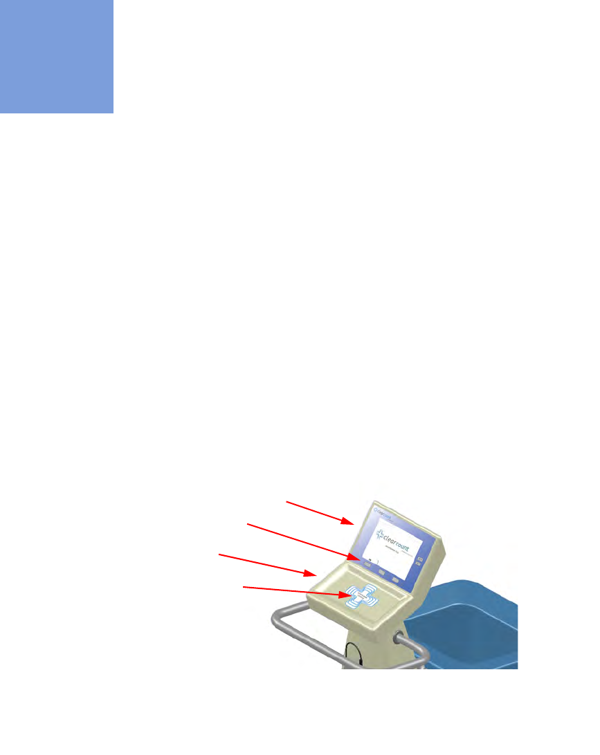
Count In Scanner
The Count In Scanner, shown in
Figure 1-1
, is used to count items into the surgical case prior to using the
items. The In-Scan Tray is located below the area marked “Touch Here to Scan”
.
The SCAN IN button is used
to activate the In-Scan Tray. As surgical sponges and towels are placed on the In-Scan Tray, it adds the tagged
items to the In-Scan Inventory. This inventory or quantity of scanned-in items appears in the IN
column of the
Count Mode screen on the display.
Table 1-1
lists the Count In Scanner components.
Figure 1-1 Count In Scanner Components
Display
In-Scan Tray
Scan In location
SCAN IN button
Chapter 1: System Description - System Components 1-2
•
•
•
•
•
•
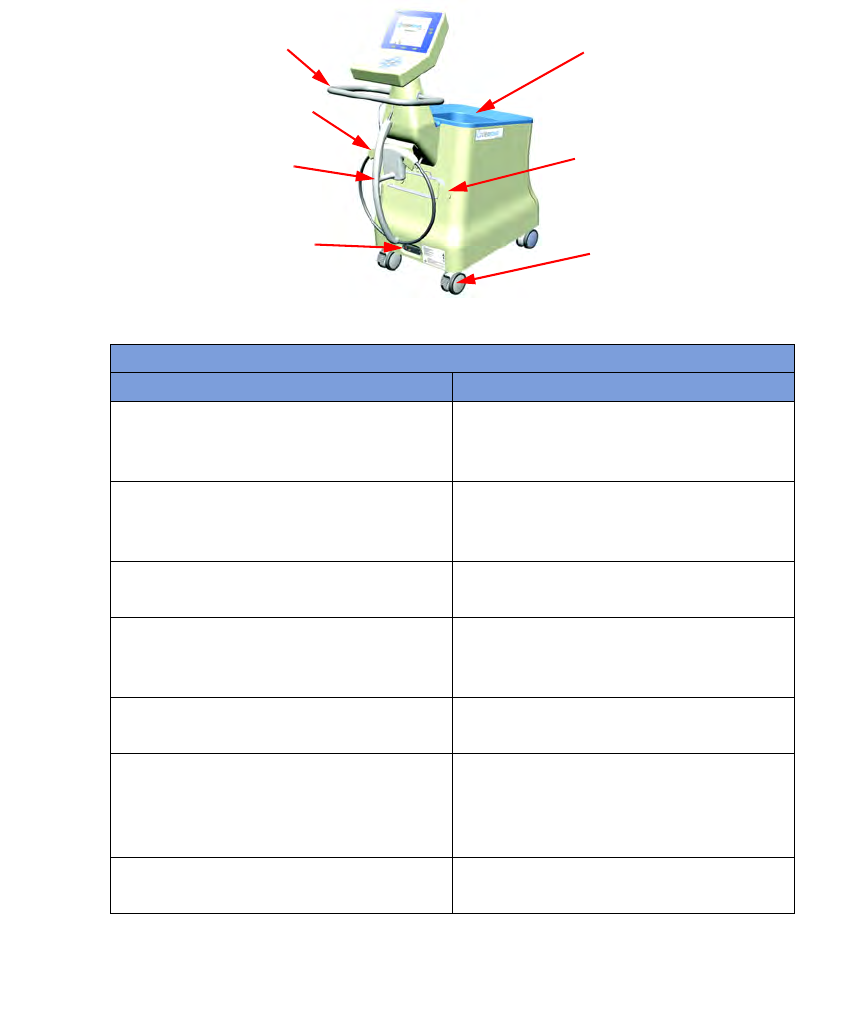
Count Out Bucket and Wand Components
The Count Out Bucket detects the RFID-tagged sponges and towels discarded into it during a surgical case.
The Handle and Casters contribute to the mobility of the SmartSponge System. The Handle is strategically
located to protect the Count In Scanner from forcefully hitting a wall, while also providing the user with a
comfortable means of maneuvering the system. The two rear casters are able to be locked in place to keep the
system stable during use. The Power Entry and On/Off Switch are located at the back of the system near the
floor. Insert the power cord into the Power Entry and then switch to On to power up the system. When not in
use, the SmartWand is mounted to the rear of the system by means of the Wand Holder; and the wand’s cord
is retained on the SmartWand Cord Wrap. See
Figure 1-2
.
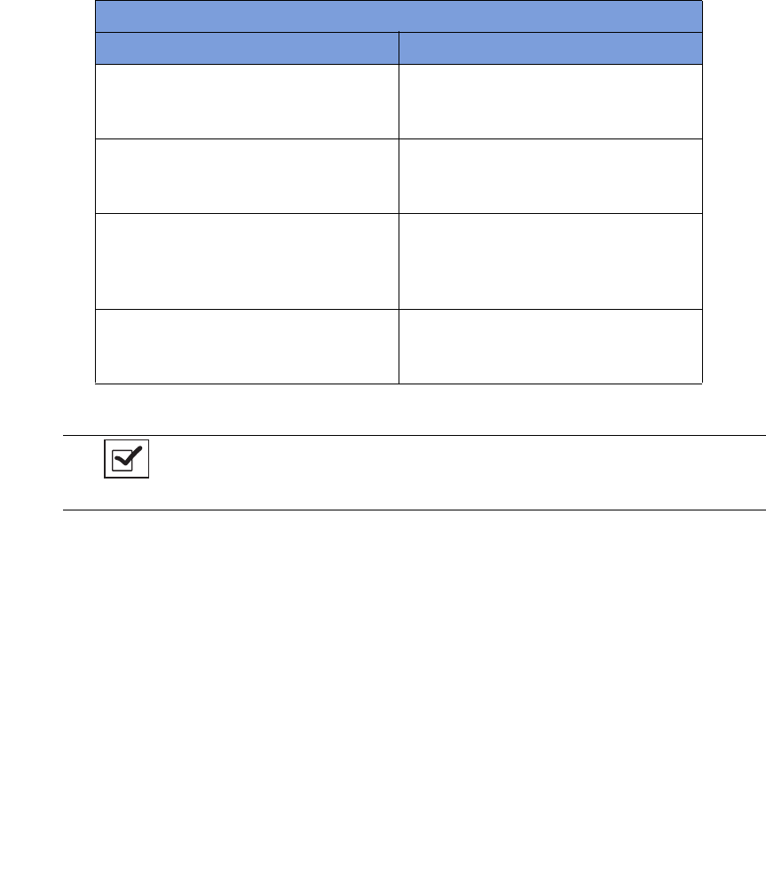
Table 1-1 Count In Scanner Components
Component Description
In-Scan Tray The area on which sponge and towel packs
are to be placed when scanning them into a
surgical case.
SCAN IN button This button activates the In-Scan Tray to
detect items introduced to the Scan In
Location.
Display Displays information for the user to track
sponge counts throughout the surgical
procedure. Also displays various modes of
operation.
Scan In Location The surface of the In-Scan Tray where
sponge and towel packs are scanned into the
surgical case.
Notes
•
The Count Out Bucket will not count items when the system is in SCANNING IN
mode.
1-3
Chapter 1: System Description
-
System Components
•
•
•
•
•
•
Figure 1-2 Count Out Bucket Components
Table 1-2 Count Out Bucket Components
Component Description
Handle Used to move the SmartSponge System.
Also positioned to protect the Count In
Scanner and display from damage.
Count Out Bucket Scans out and contains the discarded
sponges and towels after their use in
surgery.
Wand Holder Used to mount the SmartWand to the
SmartSponge System when not in use.
SmartWand Cord Wrap Keeps the SmartWand’s cord retained while
the wand is mounted to the SmartSponge
System.
SmartWand Used to detect sponges. This is done by
scanning the patient with the SmartWand.
Power Entry and On/Off Switch The Power Entry connects the SmartSponge
System to a 120 VAC power source via the
power cable. The On/Off switch toggles the
power to the system.
Locking Casters Secures the position of the SmartSponge
System.
Wand Holder
SmartWand
Handle
Power Entry and
ON-OFF Switch
Count Out
Bucket
SmartWand
Cord Wrap
Locking
Casters
Chapter 1: System Description - System Components 1-4
•
•
•
•
•
•
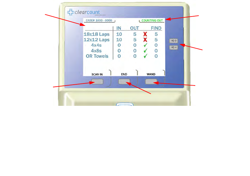
Display and Function Control Buttons
The display, function control buttons, and volume buttons are the user’s interface to the SmartSponge System.
This backlit display shows the following types of screens at various points, depending on the mode of
SmartSponge System operation:
•
Starting, Boot, and Power & Diagnostic screens (during system boot-up)
•
Standby, Ready to Count or Continuing case, and Count Mode (Scanning In/Counting Out)
•
Final Report: Counts Equal, or Final Report: Counts Not Equal
•
Wanding Mode
The Volume Control buttons allow for the adjustment of the SmartSponge System’s internal buzzers. These
may be set to four preset levels; off, low, medium, and high. The system will beep when booting up, when it
is ready to count, when sponges are scanned in, detected with the SmartWand, or scanned out, and any system
alert.
Each screen defines the operation of the control buttons for the associated mode of operation. There are three
function control buttons along the bottom of the display and two volume control buttons to the right of the
display.
Figure 1-3
shows the location of the control buttons in relation to the example screen.
Figure 1-3 Display and Control Buttons
Display
Function
Control
Button [1]
Function
Control
Button [3]
Function Control Button [2]
Volume
Control
Buttons
Mode of
Operation

1-5
Chapter 1: System Description
-
System Components
•
•
•
•
•
•
Table 1-3 Display/Controls
Display / Controls Description
Display An LCD that displays information for the
user to track sponge counts throughout the
surgical procedure. Also displays various
modes of operation.
Mode of Operation Located in the upper right-hand corner of
the Display, this indicates the current status
of the system.
Volume Control Buttons These up and down buttons control the
volume of the audible tones. The Volume of
the tones can be set to four different levels;
off, low, medium, and high.
Function Control Button [1] Allows the following actions;
ON
- Turns
the system on from Standby Mode.
SCAN
IN
- Activates the In-Scan Tray.
BACK
-
Returns to the previous screen and mode.
STANDBY
- Returns the system to
Standby Mode.
Function Control Button [2] Allows;
END
- Exits Count Mode and
proceeds to the Final Report screen for
verification before ending a case.
RESET
- Clears the detection status for a rescan in
Wanding Mode. Also
BACK
in Final
Report Mode.
Function Control Button [3] Allows;
WAND
- Switches from Counting
Out Mode to Wanding Mode.
OVERRIDE
- Allows the user to end a
case without reconciling the sponge counts
by using an Override Card.
END CASE
-
Saves case data and returns system to
Standby Mode.
BACK
- Returns to the
previous screen and mode.
Chapter 1: System Description - System Components 1-6
•
•
•
•
•
•
SmartSponge Disposables
The SmartSponge System utilizes surgical sponges and towels that have been “tagged” with an RFID
identification device. This RFID tag is about the size of a typical medicine capsule and does not contain a
battery. Because each sponge contains a tag with unique identification, the SmartSponge system can quickly
and accurately count and identify each sponge.
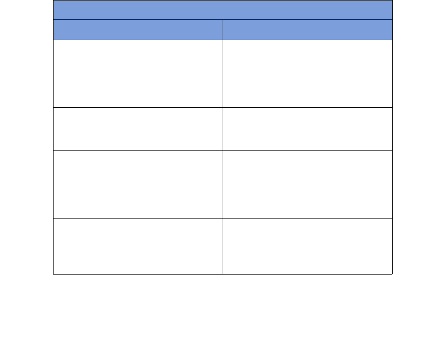
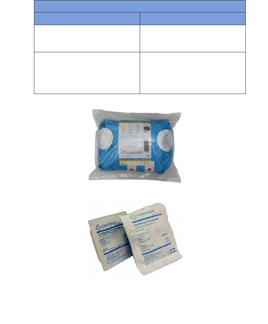
Surgical sponges are provided for surgery in two forms: pre-packaged sterile surgical kits (
Figure 1-4
) and
individual sterile packages (
Figure 1-5
). There are different procedures involved when using one presentation
versus the other. Refer to Chapter 2 of this manual for further details.
Additionally, the SmartSponge System relies on several accessories for proper use and patient care. These
accessories are described briefly in
Table 1-4
.
Table 1-4 SmartSponge Disposables and Accessories
Accessory Description
Surgical Kits A pre-packaged sterile kit of materials and
equipment assembled for a specific surgery.
Included are various banded packs of
SmartSponges for use with the
SmartSponge System.
Sterile Packages SmartSponges packaged by type for use
with the SmartSponge System that are not
pre-packaged in Surgical Kits.
Bucket Liner A large drawstring plastic bag used to
protect the Count Out Bucket from
contamination as soiled sponges are
discarded. Sterile when provided in surgical
kits.
Wand Cover A large, sterile, clear plastic sheath used to
protect the sterile field when using the
SmartWand. The sheath covers the wand
and a portion of the wand cord.
1-7
Chapter 1: System Description
-
System Components
•
•
•
•
•
•
Figure 1-4 Example of Sterile Surgical Kit
Figure 1-5 Example of Sterile Sponge Packages
Override Card A Smart Card used by the authorized staff
member to enable an un-reconciled case to
be closed.
SmartTag / SmartTag Special A sticker applied between the sheets of the
OR table prior to surgery, which allows the
user to ensure that the SmartWand is
operational. (SmartTag Special is only for
use with carbon fiber top OR tables)
Table 1-4 SmartSponge Disposables and Accessories (Continued)
Accessory Description
Chapter 1: System Description - System Components 1-8
•
•
•
•
•
•
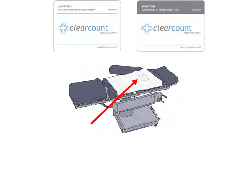
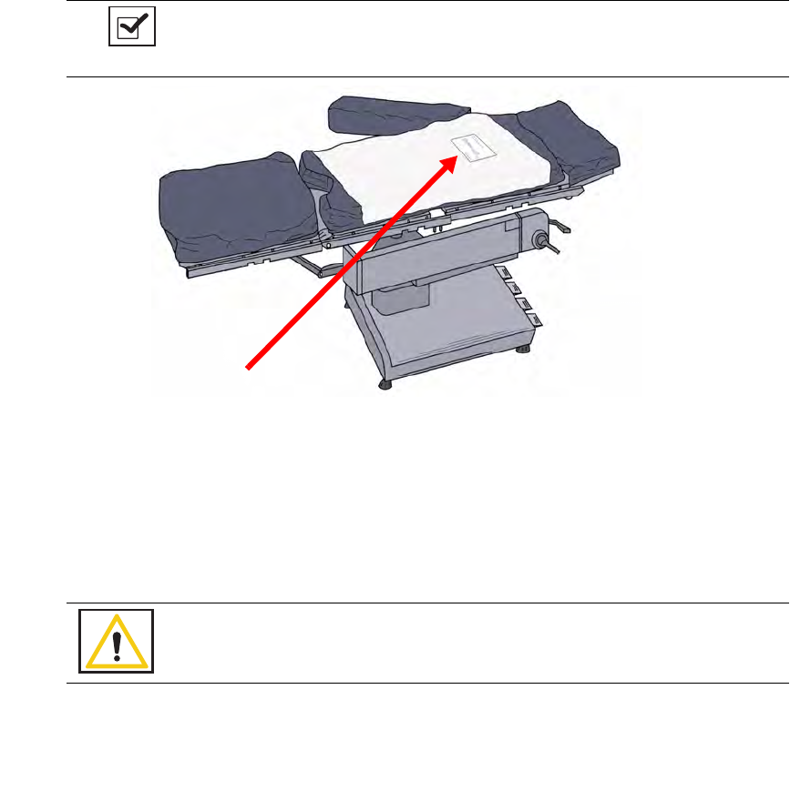
SmartTags
SmartTags are passive RFID labels that have an adhesive backing (see
Figure 1-6
). Prior to surgery, a
SmartTag is positioned under the surgical site between the bottom sheet and the draw sheet on the OR table.
Figure 1-7
shows a typical position of the SmartTag on the OR table.
The purpose of the SmartTag is to provide confidence to the user that the SmartWand is scanning the entire
depth of the surgical site. Using a SmartTag is a direct indication of effective scan depth and thereby better
than proxy methods such as BMI. Detection of the SmartTag assures the user that the wand is functioning and
being used properly such that any SmartSponges remaining inside the patient can be identified quickly.
There are two types of SmartTags.
•
The standard SmartTag is for use with OR tables with phenolic tops. These are the most common OR
tables.
•
SmartTag Special is for use on OR tables with carbon-fiber tops. These are less common.
It is important to use the correct SmartTag so that indication of scan depth by the wand is dependable. If you
are uncertain, ClearCount can provide assistance at the time of installation to help determine which SmartTag
type should be used with your OR tables.
Figure 1-6 SmartTag / SmartTag Special
Figure 1-7 Location of SmartTag on OR Table
SmartTag Special
SmartTag
1-9
Chapter 1: System Description
-
System Components
•
•
•
•
•
•
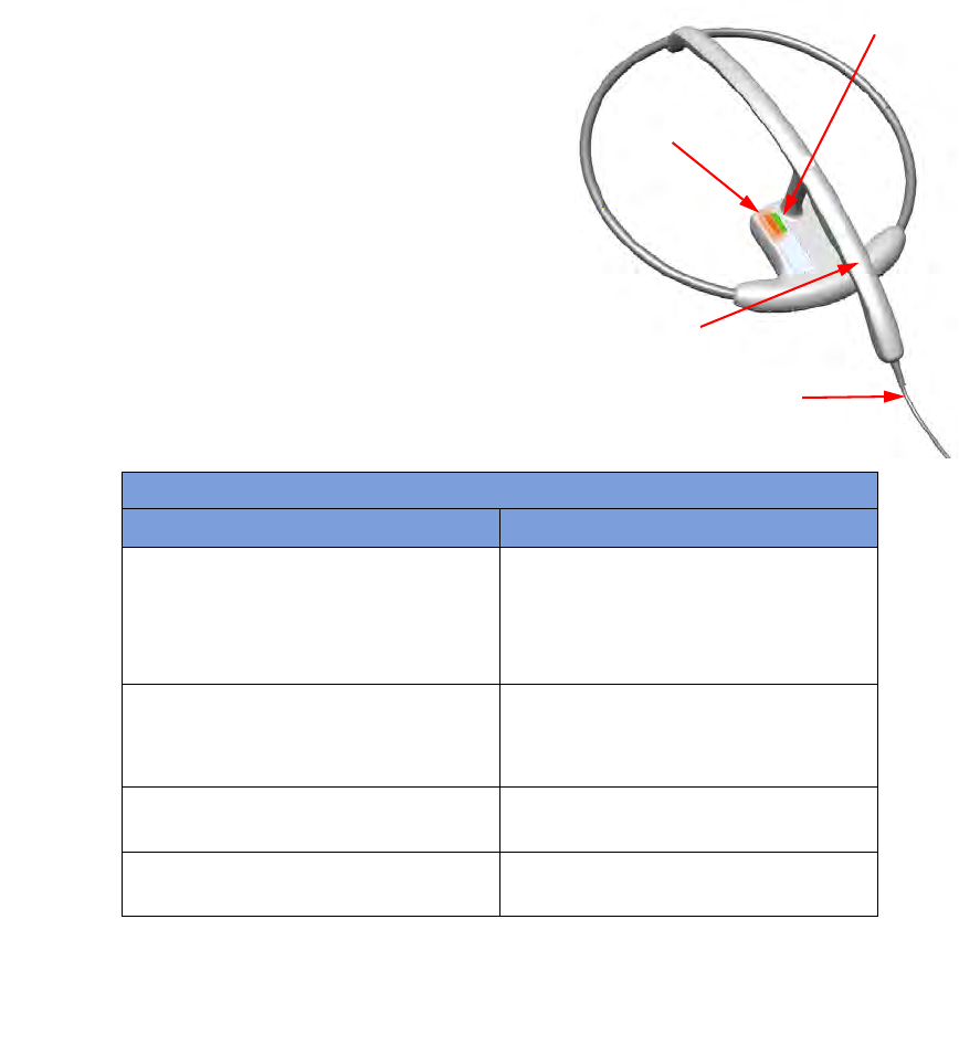
SmartWand
The SmartWand, shown in
Figure 1-8
is a patient scanning wand that houses an antenna for detecting
ClearCount SmartSponges.
The Handle of the wand is designed to ease the process of
sterile sheathing while handing it into the sterile field by giving
each person a place to grip. The Wand Cord exits the back end
of the handle and connects to the Wand Connection on the back
of the SmartSponge System. Two LEDs mounted on the wand
provide visual cues about the system’s operation. The Bi-Color
LED displays detection status while the Single Color LED
displays the wand’s power status. To scan the patient; Press the
WAND button after the wand has entered the sterile field, hold
the wand by its handle, pass it over the body maintaining a
distance of 2 to 3 inches above, while completing five head to
toe sweeps shown on the display at a rate of 7 inches a second.
Refer to Chapter 2 for the complete patient scanning
procedure.
Figure 1-8 SmartWand
Table 1-5 SmartWand
Component Description
Bi-Color LED Changes with the wand’s detection status.
Solid Blue - SmartTag detected
Off - SmartTag not yet detected
Solid Amber - SmartSponge detected
Single-Color LED Changes with the wand’s status.
Solid Green - Wand attached
Off - Wand not attached or system error
SmartWand Handle Used to hold the SmartWand while
performing the patient scan.
SmartWand Cord Provides power and communications to the
SmartWand from the SmartSponge System.
Bi-Color LED
Single Color LED
Handle
Wand Cord
Chapter 1: System Description - System Components 1-10
•
•
•
•
•
•
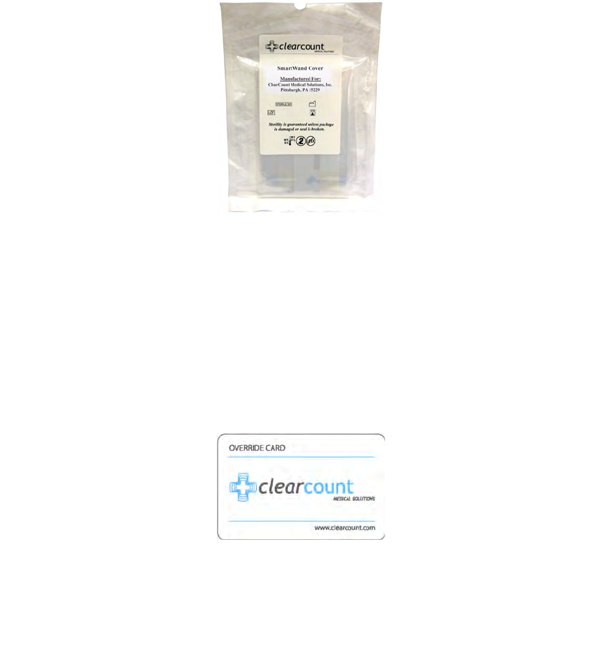
Wand Cover
A sterile wand cover is used when the patient needs to be scanned with the SmartWand. The cover is passed
into the sterile field and then applied to the SmartWand as it is handed in.
Figure 1-9
shows the wand cover
package.
Figure 1-9 Sterile Cover for SmartWand (outside of surgical kit)
Override Card
The SmartSponge System requires the user to acknowledge the closure of an un-reconciled surgical case. The
term “un-reconciled” indicates that the number of sponges scanned in and counted out is not the same. The
user acknowledges this condition by placing the system into Override Mode. This is done by pressing the
OVERRIDE button on the Final Reports: Counts Not Equal screen to enter the Override Mode and end the
case with unequal counts. The user then places the RFID-tagged Override Card on the In-Scan tray until an
audible alert is heard and the display confirms.
Figure 1-10
shows the Override Card. Each use of the Override
Card is logged into the system’s database. A notation of this discrepancy should also be recorded on the patient
record.
Figure 1-10 Override Card

2-1
•
•
•
•
•
•
• • • • • •
Chapter 2: Initial Setup and Operation
Chapter 2 describes the initial setup of the SmartSponge® System. The setup includes the following topics:
•
Powering on the SmartSponge System
•
Placing the SmartTag
•
Boot-up screens
•
Standby mode
•
Setting up for surgery
•
Using pre-packaged sterile surgical kits
•
Using individual sterile packages
The chapter also covers operating the SmartSponge System to perform the following surgery-related
functions:
•
Using the System in Count Mode
•
Scanning items into and out of surgery
•
Requesting final item count reports
•
Obtaining the final report: counts equal
•
Obtaining the final report: counts not equal
•
Scanning a Patient for Retained Items
•
Using the SmartWand
•
Restoring Power
Chapter 2: Initial Setup and Operation - Initial Setup 2-2
•
•
•
•
•
•
Initial Setup
Powering on the SmartSponge System
The following procedure describes how to set up the SmartSponge System before each surgical case. Before
its initial use, a technician will unpack, set up, and check the system to ensure it is functioning properly. If
problems with the system occur later during its use, call ClearCount Medical Solutions.
After the SmartSponge System has been set up, place it in the desired position in the Operating Room (OR)
and lock the rear casters.
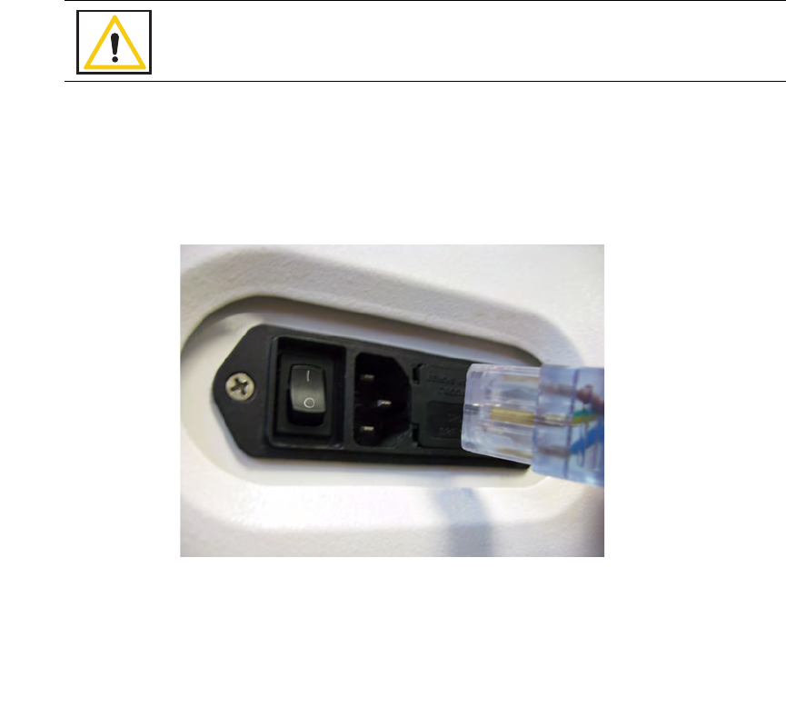
Step 1 Connect the system to a grounded, 120 VAC power outlet using the power cord supplied.
Step 2 Check that the other end of the power cord is securely plugged into the power entry module of
the system.
Step 3 Set the power (|/O) switch shown in Figure 2-1 to the | (on) position. There will be an audible
tone and a series of power-up screens that briefly appear on the display.
Figure 2-1 Location of On/Off Switch
Warning!
Inspect the power cord prior to each use, and replace it if damaged. A frayed or worn
cord presents an electrical shock hazard that may result in personal injury or death.
2-3
Chapter 2: Initial Setup and Operation
-
Initial Setup
•
•
•
•
•
•
Placing the SmartTag
Before the start of a surgery, place a SmartTag between the surgical sheets under the patient. The standard
SmartTag is to be used on phenolic top OR tables while the SmartTag Special is for use with carbon fiber top
OR tables.
Figure 2-2
shows a SmartTag and its placement. The SmartTag is an adhesive sticker that contains
a radio-frequency identification (RFID) tag. This tag provides feedback to the SmartSponge System that the
SmartWand is reading through the depth of the patient when a scan is performed.
Figure 2-2 SmartTag Placement
During pre-surgery setup, proceed as follows:
Step 1 Peel the backing from the SmartTag.
Step 2 Position the SmartTag below the surgical site and apply between the bottom sheet and the draw
sheet.
Step 3 Place the tag adhesive-side down.
Notes
•
If the wrong SmartTag is used on the wrong type of table, it will perform
improperly.
Warning!
The SmartTag is not approved for application to the patient’s skin.
Chapter 2: Initial Setup and Operation - Initial Setup 2-4
•
•
•
•
•
•
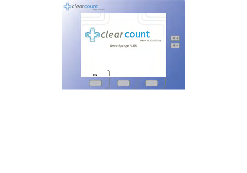
Boot-up Screens
After the on/off switch is set to on (|), the system will produce an audible tone, and the Starting screens shown
in
Figure 2-3
will appear.
Starting Screen
The Starting Screen, shown at the top of
Figure 2-3
, appears on the display first for 10 seconds after the on/off
switch is set to on.
Boot Screen
The Boot Screen, which follows the Starting Screen appears for 3 seconds. Shown in the center of
Figure 2-
3
, this screen shows the versions of system firmware and the device (SmartSponge System) identification (ID).
Diagnostic Screen
The Diagnostic Screen, shown at the bottom of
Figure 2-3
, appears for 9 seconds. This screen has a Progress
Bar that fills in from left to right in segments. When the bar completely fills in, the system produces an audible
tone, and displays the Standby Screen. See
Figure 2-4
. The Standby
Screen remains on the display until the
user presses the ON button to start or continue a surgical case.
Notes
•If the device is powered on without the SmartWand connected, the device
will display a “Please Connect the Wand” screen. To advance to Count
Mode, plug in the wand and a green check-mark will appear in the check-
box next to connect the wand. The system will then advance to Count
Mode.

2-5
Chapter 2: Initial Setup and Operation
-
Initial Setup
•
•
•
•
•
•
Figure 2-3 Boot-up Screens
Boot Screen
Starting Screen
Diagnostic Screen
Chapter 2: Initial Setup and Operation - Initial Setup 2-6
•
•
•
•
•
•
Standby Mode
Following the startup screens, the Standby
screen appears, and the system enters Standby Mode. The system
should be left in this state when not in use.
The Standby Mode of operation is the starting point for operating the SmartSponge System. The system can
remain in this mode for as long as necessary while you prepare for surgery. The SmartSponge System enters
the standby mode under the following conditions:
•
When the system powers up.
•
When you press the
STANDBY
button on the Final Report screen during a surgical case.
•
After the
END CASE
button is pressed to save the case data and power down the device.
•
Upon restoration of power following a power failure.
When you are ready to begin a new surgical case, press the ON button on the Standby screen. If the Standby
Mode has been entered during a case (either by pressing
STANDBY
or due to power failure), pressing
ON
will resume the case in progress.
Figure 2-4 Standby Screen
2-7
Chapter 2: Initial Setup and Operation
-
Initial Setup
•
•
•
•
•
•
Setting Up for Surgery
With the system in position, and the SmartTag placed between the sheets on the OR table, you are ready to
prepare the sponges and other supplies necessary for surgery. The SmartSponge System must be used with
ClearCount sponges. These may either be packages of sterile sponges, or sponges in sterile surgical kits. The
procedure for using one type versus the other is slightly different, as noted below.
Using Sterile Surgical Kits
Step 1 Locate and open the surgical kit. Using sterile technique, locate the following components:
•
Bucket Liner
•
Wand Cover - this should be set aside within the sterile field in case the patient must be scanned for
sponges.
•
Surgical sponges and towels - these will be contained within a paper band with the ClearCount logo.
Banded sponges should be scanned in one bundle at a time. Do not remove the band until the bundle
has been scanned in.
Step 2 Move the system as close as possible to the sterile field.
Step 3 Using aseptic technique, cover the Count In Scanner and display with the Bucket Liner. Make
sure the In-Scan Tray and display are completely covered. Proceed to scan sponges and towels
into the surgical case.
Step 4 After the sponges and towels have been scanned in, remove the Bucket Liner from the Count In
Scanner and install it into the Count Out Bucket.
Using Packaged Sponges
Step 1 Locate the following items:
•
All of the sponges and towels that will be used in the surgical case
•
Bucket Liner
•
Pre-packaged sterile wand cover - this will be used if the patient needs to be scanned with the
SmartWand.
Step 2 Install the liner into the Count Out Bucket.
Step 3 Scan in sponges and towels while still in the sterile packaging.
Notes
•If a bundle of sponges within the surgical kit is damaged or unable to be
scanned into the surgical case, replace that bundle with a package of
sterile ClearCount sponges.

Chapter 2: Initial Setup and Operation - Operations 2-8
•
•
•
•
•
•
Operations
Count Mode Operation
Count Mode is the primary mode of operation for the SmartSponge System. It is used for scanning sponges
into and out of the case during surgery. The SmartSponge System remains in Count Mode for the majority of
the surgery (unless switched by the user), until it is complete and the sponge count has been reconciled. This
mode consists of two available functions; Scanning In and Counting Out (appears on the mode of operation
line of the display in the top right). These functions of Count Mode are cycled by the first Function Control
button which changes from
SCAN IN
to
BACK
. While in the Count Mode, the display is continually
updating the number of sponges scanned into and out of the case by either the In-Scan Tray or Count Out
Bucket, depending on the mode selected. To enter Count Mode, press the ON button while in the Standby
Mode.
From the Count Mode screen, shown in
Figure 2-5
, you can:
•
Press
SCAN IN
to scan sponges and towels into the surgery. (In-Scan Tray active)
•
Press
BACK
to return to Counting Out Mode to discard used items. (Count Out Bucket active)
•
Press
END
to display the Final Report Screen.
•
Press
WAND
to activate the SmartWand and perform a patient scan.
2-9
Chapter 2: Initial Setup and Operation
-
Operations
•
•
•
•
•
•
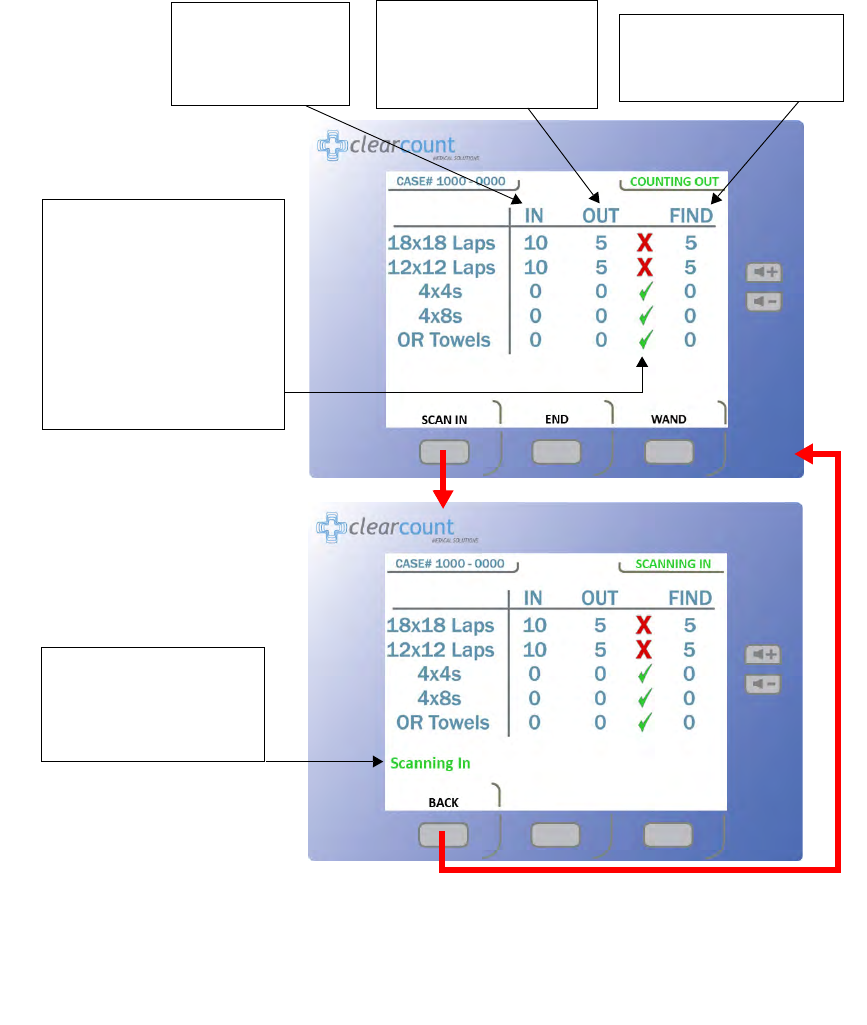
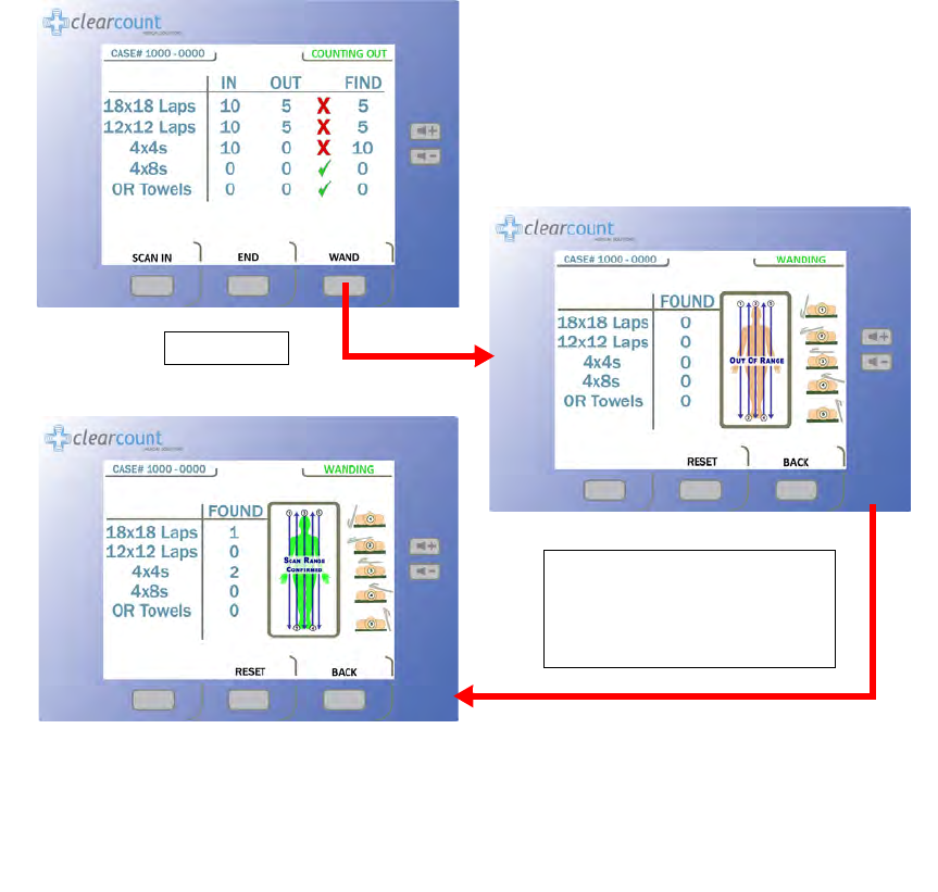
Figure 2-5 Count Mode Screen
The
IN
column lists
the number of items
that have been
scanned into surgery.
The
OUT
column lists the
number of items that have
been discarded into the
Count Out Bucket.
The
FIND
column lists the
number of items not
reconciled by the system.
A green check mark appears
if the number of items
scanned into surgery is equal
to the number of items
discarded into the Count Out
Bucket. If the number of
items in the
IN
and
OUT
columns are not equal, a red
X
will appear.
Scanning In
appears on
the screen when the
SCAN
IN
button is pressed to
activate the In-Scan Tray.

Chapter 2: Initial Setup and Operation - Operations 2-10
•
•
•
•
•
•
Scanning Items Into and Out of Surgery
Step 1 Press the SCAN IN button to activate the In-Scan Tray; “Scanning In” will appear on the
screen as notification. Scan packages of SmartSponge surgical sponges and towels into the
surgical case by holding them flat on the In-Scan Tray over the area marked “
Touch Here to
Scan”
. Hold the item until an audible tone is heard, and the system adds the pack contents to
the IN (inventory) column. See Figure 2-5. If the system displays the alert “Pack Not
Verified - Retry Pack” attempt to re-orient the package and scan again. If the alert “Discard
Pack” is displayed, throw out the defective package and start again with a new one. Packages
of sponges and towels must be scanned one package at a time. If two or more packages are
detected by the In-Scan Tray at once the system will display the “Multiple Packs Detected”
alert. Remove the scanned packages and re-scan one at a time. Do not rest sponge packages or
any other items on the In-Scan Tray.
Step 2 After sponges are scanned in, they may be opened to the sterile field using standard sterile
technique. ClearCount SmartSponges are to be used in the same manner as generic surgical
sponges.
Step 3 Sponges may be discarded into the Count Out Bucket at any time during the surgical case.
If a sponge(s) that has not been scanned in is detected by the Count Out Bucket, the system will
prompt the user on what action to take with the detected sponge(s). There is an option to
Accept
the
detected sponge(s) into the case or
Decline
them. See
Figure 2-6
. Accepting infers that a sponge(s)
Warning!
•
Holding items that
have not been
scanned in too close to the Count Out
Bucket may result in the items unintentionally being detected prior to use.
Follow the on screen prompts to remove the sponges from the scanned out
inventory or accept them into the case.
•
Holding items that
have been
scanned in too close to the Count Out Bucket
may result in the items unintentionally being detected prior to use. Dispose of
any items into the Bucket that have been scanned in and then scanned out
(detected) by the Count Out Bucket prior to use.
•
For the system to function, use only ClearCount disposables.
•
Do not place sponges from a previous surgical case into the Count Out Bucket.
This will cause the sponge counts not to reconcile properly.
•
Do not cut or tear SmartSponge disposables, as their RFID tags may separate.
•
Do not fill the Count out Bucket beyond its top edge. Items above the top edge
may not be counted.

2-11
Chapter 2: Initial Setup and Operation
-
Operations
•
•
•
•
•
•
that was not scanned in was intentionally discarded into the bucket. Declining infers that a sponge(s)
was held too close to the Count Out Bucket prior to being scanned in (in this case move the sponges
away from the bucket and select
Decline
).
If declined, the system will go back to the previous counts and continue. Before pressing
Decline
,
be sure to remove the detected sponge(s) from the vicinity of the Count Out Bucket or the system will
continue to prompt for Accept/Decline of the detected sponge(s). If the sponge(s) is accepted into the
case, the user must re-confirm their selection and the sponge(s) will be added to the current counts.
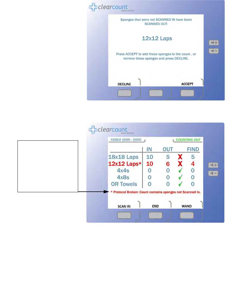
All absent sponges from the same package as the accepted sponge(s) automatically become accepted
into the case. The package contents will be added to the
IN
column, with the detected sponge(s)
entered into the
OUT
column. The subsequent sponges from the package will not need to be
accepted; they will already exist in the
FIND
column. A note will then be displayed stating that
protocol has been broken (this will not affect system performance or function). See
Figure 2-7
. This
function will accommodate accidental or intentional scenarios.
If more than
50
SmartSponges are in the Count Out Bucket, the alert “
Change Bag - Bucket
Limit Has Been Exceeded
” appears. When this alert occurs, remove the sponges from the Count
Out bucket and replace the bucket liner (if necessary). Sponge counts are not affected by removing
sponges from the Count Out Bucket.
If the “
Change Bag
” message is ignored and the sponge counts reach
70
, the system alert “
Bag
Overflow Warning - Bucket Limit Has Been Exceeded
” is displayed. This message will
persist until sponges are removed from the bucket. The system will give a system warning and
require the system to be restarted if the sponge count reaches
80
. These measures are taken to assure
accurate sponges counts. See Chapter 4 for explanations of System Alerts and Warnings.
Notes
•When using the In-Scan Tray, it is best to keep it turned away from the
Count Out Bucket. This prevents items from being prematurely scanned
out due to being too close to the Count Out Bucket.
•
The Count Out Bucket will not count items while the system is in
Scanning
In
mode. Likewise, the In-Scan Tray will not scan items in while the system
is in
Counting Out
mode.
•
Scanning In mode will revert back to Counting Out mode after
60
seconds of
inactivity.
•
Sponges contained within count bags or pocket-type devices may be
discarded directly into the Count Out Bucket.
Chapter 2: Initial Setup and Operation - Operations 2-12
•
•
•
•
•
•
Figure 2-6 Example of Decline or Accept Screen
Figure 2-7 Example of Protocol Broken Note
Protocol Broken
note
shows up after the user
accepts sponges into the
Count Out Bucket
inventory without first
scanning them into the
case via the In-Scan Tray.
2-13
Chapter 2: Initial Setup and Operation
-
Operations
•
•
•
•
•
•
Requesting Final Item Count Reports
When placed in the
Final Report
Mode, the system provides final sponge counts for the surgery.
Before
ending the case, verify that the quantities displayed in the
IN
and
OUT
columns on the
Count Mode
screen are equal, and a green check mark appears next to them. See Figure 2-5. The green check mark
indicates that the count is reconciled. If the user has accepted sponges into the case that hadn’t been pre-
scanned in using the In-Scan Tray, the “Protocol Broken” note will show up on the Final Report
screen. This will not affect the final counts but it will be saved with the rest of the case data.
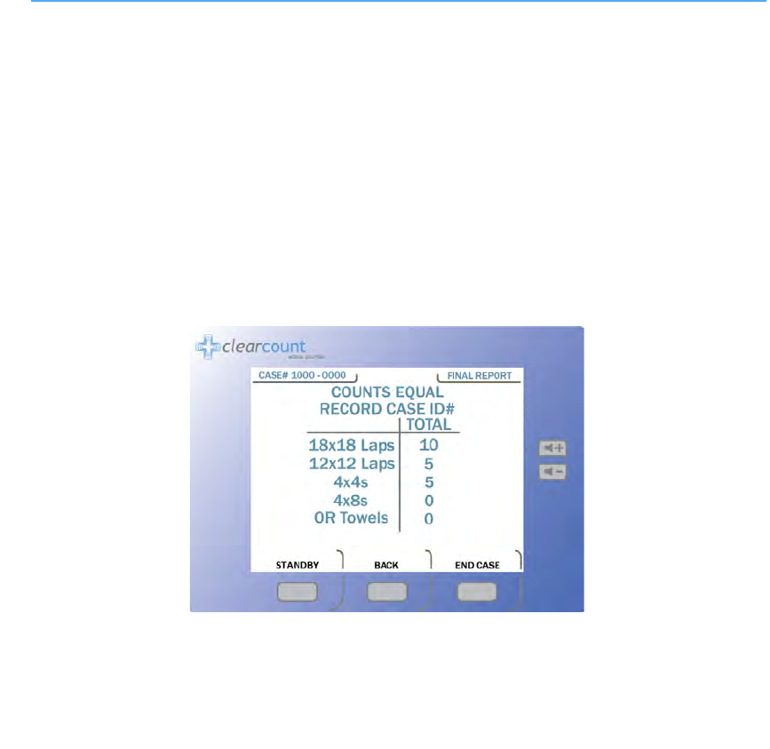
Obtaining the Final Report: Counts Equal
Step 1 When all items used in the surgery have been discarded into the Count Out Bucket, press the
END
button on the
Count Mode
screen.
If the counts are reconciled, the final report indicates that all counts are correct. See
Figure 2-8
.
Step 2 Enter the case number in the patient’s record.
Step 3 Press the
END CASE
button to close the surgical case and the
Ending Case
progress bar will
appear. Once the case has been closed, the system returns to Standby Mode.
Step 4 Remove the bag liner that contains the discarded sponges from the Count Out Bucket. Dispose
of the bagged items according to the standard protocol for your hospital.
Step 5 Clean the entire SmartSponge System according to the procedure in Chapter 3 before entering
it into the next surgical case.
Figure 2-8 Final Report Screen: Counts Equal

Chapter 2: Initial Setup and Operation - Operations 2-14
•
•
•
•
•
•
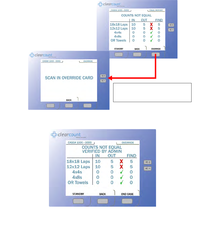
Obtaining the Final Report: Counts Not Equal
If counts are not reconciled when you press the
END
button, the
Counts Not Equal
screen appears.
Figure
2-9
shows the screen progression to scan the Override card. The
OVERRIDE
button allows the case to be
closed if the counts are not reconciled. Sponges may be intentionally withheld from the Count Out Bucket for
procedural or clinical reasons. Alert the OR manager, and note this on the patient’s record along with the Case
Number. See the upper left corner of the screen in
Figure 2-5
for the Case Number location.
The SmartSponge System requires that the user acknowledge the closure of an unreconciled case. This is
accomplished by using the Override Card. This card is an RFID-tagged card included with the system at the
time of shipment. The Override Card is used by placing it on the In-Scan Tray until an audible alert is heard,
while the system is in the
OVERRIDE Mode
.
Step 1 Press the END button at the bottom of the display.
Step 2 With the COUNTS NOT EQUAL press the OVERRIDE button.
Step 3 The person responsible for the Override card will need to present the card. Scan the Override
card by placing it onto the In-Scan Tray and holding it there until an audible alert is heard. The
VERIFIED BY ADMIN screen shown in Figure 2-10 will then appear.
Step 4 Enter the case number in the patient’s record.
Step 5 By pressing the END CASE button again, the Ending Case and the Powering Down screens
will appear. The system then displays the Standby screen and waits to start a new case.
Step 6 Remove the bucket liner that contains the discarded sponges from the Count Out Bucket.
Dispose of the bagged sponges according to the standard protocol for your hospital.
Step 7 Clean the SmartSponge System according to the procedure in Chapter 3 before entering it into
the next surgical case.
2-15
Chapter 2: Initial Setup and Operation
-
Operations
•
•
•
•
•
•
Figure 2-9 Final Reports Screen: Counts Not Equal
Figure 2-10 Counts not Equal Verified By Override Screen
When you press the
OVERRIDE
button,
the
SCAN IN OVERRIDE CARD
screen appears.
Chapter 2: Initial Setup and Operation - Operations 2-16
•
•
•
•
•
•
Wand Mode Operation
The SmartWand may be used to scan patients for retained ClearCount sponges and towels at any point during
the surgery. Onscreen instructions guide the user on performing a patient scan. If the SmartWand detects a
retained item(s) in a patient, an audible alert is produced while the amber indicator on the wand flashes and
the screen displays the type and quantity found, as shown in
Figure 2-11
.
The SmartWand performs best when passed over the patient in a slow, steady fashion, no faster than 0.2
m/second (approximately 7 inches/second). Maintain a distance of 2 to 3 inches above the patient. On a typical
patient, each scan pass should take approximately 5 seconds to complete.
Figure 2-11 Wand Mode Screen
Press WAND
When the SmartTag is detected
the patient marker will change to
green and any sponges found will
show up by type and quantity.
2-17
Chapter 2: Initial Setup and Operation
-
Operations
•
•
•
•
•
•
Scanning Procedure
Step 1 Remove the SmartWand from its holder below the Count In Scanner and free its cable.
Step 2 Cover the SmartWand with a sterile cover using sterile technique while passing the wand into
the sterile field.
Step 3 Press the
WAND
button on the
Count Mode
screen to activate the wand. The green LED on the
handle will start to flash when the wand is activated. The
Wand Mode
screen shown in Figure
2-12 will then appear.
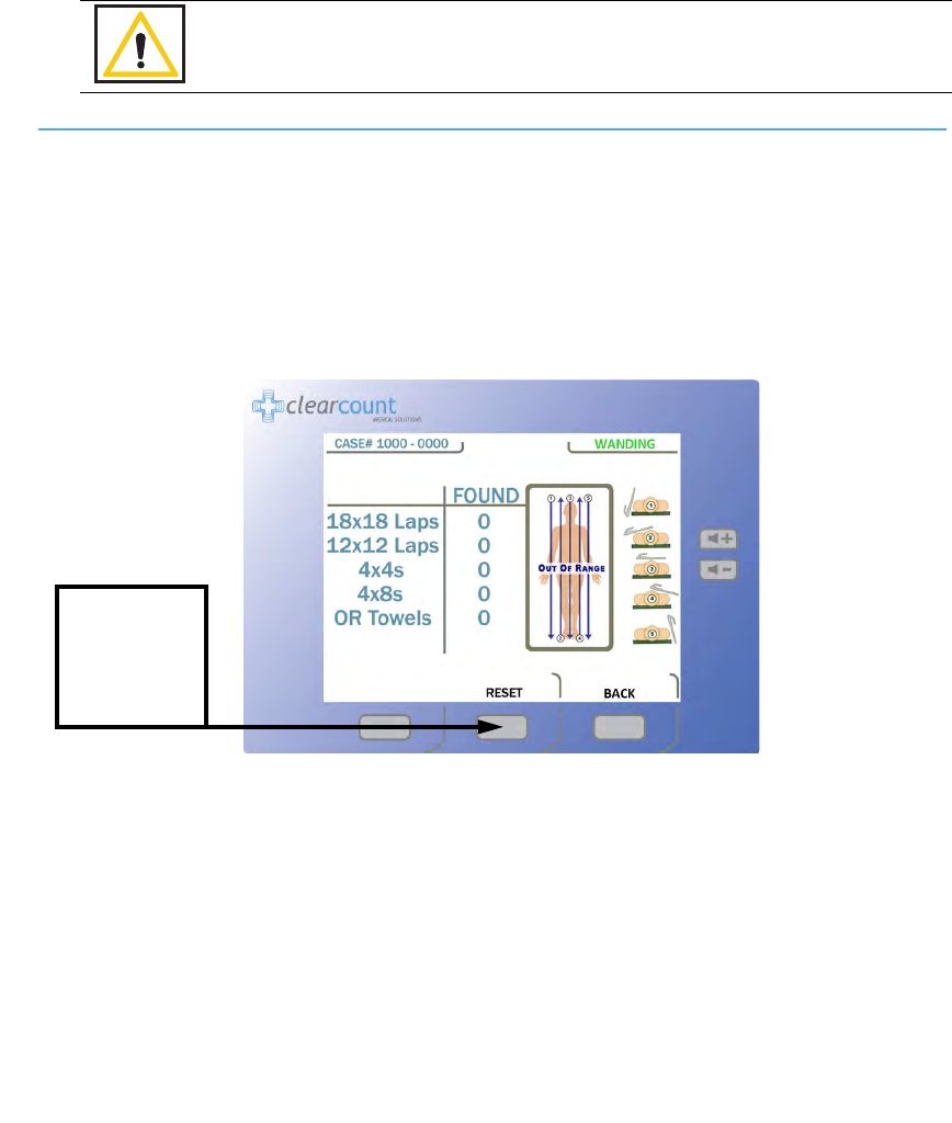
Figure 2-12 Wand Mode Screen
Step 4 Using the handle, hold the SmartWand over the site where the SmartTag has been placed. When
detected, the green LED on the wand will stay illuminated and the screen displays the message
“
Scan Range Confirmed”
. This message confirms that the wand is reading completely through
the patient.
Without a SmartTag under the patient, the user is unable to verify they are scanning completely
through the patient. However the scanning operation may still be successful.
Warning!
•
Using the SmartWand without a sterile wand cover may contaminate the sterile
field.
To clear the
detection counts
from the screen,
press the
RESET
button.
Chapter 2: Initial Setup and Operation - Operations 2-18
•
•
•
•
•
•
Step 5 Slowly scan the patient from head to toe moving at a rate of 0.2 meters a second (7 inches/sec),
holding the SmartWand 2 to 3 inches above the patient. Follow the onscreen instructions shown
in Figure 2-12.
It is important to do all the scans(1-5) in order to most accurately identify potential
retained sponges. (
Figure 2-13
)
If the wand detects an item retained in a patient, the system produces an audible alert while the amber
light on the wand flashes, and the Wand Mode screen displays the type and quantity of the item(s).
Search the patient for the retained item(s).
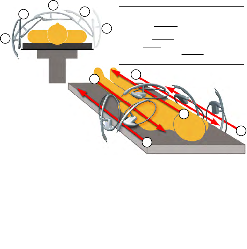
Figure 2-13 Patient Scan Procedure
Step 6 When the patient scan is complete, press the
BACK
button to return to the
Count Mode
screen.
If a retained item was found, place the item into the Count Out Bucket.
Step 7 Remove the SmartWand from the sterile field. Remove the sterile cover and discard it according
to the standard protocol.
Step 8 Return the SmartWand to its holder and the cable to the cord wrap.
1
2
2
5
4
3
3
5
4
1
•
Hold the wand
2-3
inches above the patient while
scanning at a rate of
7
inches a second for each pass.
•
1
Starting at
90 degrees
to the patient, scan from head
to toe past the surgical sight.
•
2
Scan at a
45 degree
angle to the patient.
•
3
Scan
Parallel
to the patient.
•
4
Scan opposite of
2
at a
45 degree
angle.
•
5
Scan opposite of
1
at
90 degrees
.

2-19
Chapter 2: Initial Setup and Operation
-
Operations
•
•
•
•
•
•
Restoring Power
In the event of a power failure, move the power cord from a standard wall outlet to a red battery backed outlet.
Restart the SmartSponge System with the On/Off switch in the up (ON) position. When the
StandBy
screen
appears press the
ON
button to continue the current case. The screen will prompt the user that it is continuing
from the current case. Sponge counts are resumed upon the return of power.
If the power cord is accidentally unplugged during use, replace it into the power entry module or the wall
outlet. With the On/Off switch in the ON position the
StandBy
screen will appear. Press the
ON
button to
resume the current case. All sponge counts are stored in the SmartSponge System’s database whenever there
is a loss of power. Sponge counts are resumed upon the return of power.
Notes
•
Remove instruments from the surgical site prior to scanning with the SmartWand.
•
Before removing the SmartWand from the sterile field, the user should return the
system to Count Mode to reduce the chance of inadvertently detecting items in the
path of the wand.
•
While in Wand Mode do not set the wand on large metal surfaces. If this occurs,
remove the wand from the surface and give the system 20 seconds to readjust.
•
Do not attempt to scan trash cans or other metal receptacles for disposable items,
as the wand may not be able to detect them.
•
While in Wand mode do not place the SmartWand on the Count Out Bucket or on
the Count In Scanner: the wand will fail to operate. Removing the wand from
these locations will restore normal functionality.
•
Do not use the wand in conjunction with any large reusable, capacitive-coupled
return electrode systems that are placed under the patient for electosurgical
devices, as the read range of the wand will be drastically reduced.
•
When scanning a patient, hold the SmartWand only by its handle.
3-1
•
•
•
•
•
•
• • • • • •
Chapter 3: Cleaning and Maintenance
This chapter includes a post-surgery cleaning procedure for the SmartSponge System. Also included is
information regarding routine maintenance of the system.
Before cleaning the system or performing maintenance on it, check that:
•
The SmartSponge System is off
•
The system is unplugged from its 120 VAC power source
Notes
•
No disassembly is required prior to cleaning.
3-2
Chapter 3: Cleaning and Maintenance
-
Cleaning Instructions
•
•
•
•
•
•
Cleaning Instructions
Collect the following supplies for cleaning the SmartSponge System:
•
Disposable cloths
•
Rubber gloves
•
Hospital grade disinfectant solution. (Follow the disinfectant manufacturer’s instructions regarding the
duration of contact time for specific biological contaminants.)
Cleaning the System
Step 1 Unplug the power cord from the power entry module.
Step 2 Pre-clean surfaces by removing any contaminants with a damp cloth and wiping them dry.
Step 3 Wipe the entire length of the cord with disinfectant.
Step 4 Wipe down the entire system; including the display, the Count In Scanner, all four sides of the
Count Out Bucket (inside and outside), the SmartWand, its cable and holder, and all four casters
with disinfectant.
Step 5 After disinfectants dry on the surface or according to manufacturer’s instructions, rinse it with
a water-dampened cloth.
Warning!
The System needs to be unplugged from it’s power source before cleaning of the wand,
box, and cords can take place.
Caution!
Do not immerse the wand or apply cleaning fluids directly to the wand, but apply the
solution with a dampened cloth; otherwise damage to the electronics could occur.

Chapter 3: Cleaning and Maintenance - Maintenance 3-3
•
•
•
•
•
•
Maintenance
ClearCount recommends that routine maintenance be performed on the SmartSponge System according to the
following schedule:
Frequency Required Action Responsible Party
Per hospital protocol Follow the cleaning procedure. User
Prior to each use Visually inspect the SmartWand’s cord
and power cord for fraying and signs of
wear. Check for cracks or other damage
to system components. Make sure the
wand antenna is not bent and the wand
housing is not damaged.
User or maintenance personnel
Monthly Check for any damage to the wand
housing, wand antenna, display, user
controls, the Count In Scanner, the Count
Out Bucket, and the power switch. Also
check for correct operation of the LEDs
on the wand housing by scanning a
SmartTag and SmartSponge.
Maintenance personnel
Annually Annual check per the service manual. ClearCount Medical Solutions
101 Bellevue Road
Pittsburgh, PA 15229
(888) 931-0787

4-1
•
•
•
•
•
•
• • • • • •
Chapter 4: Troubleshooting
This chapter describes the alerts, warnings, and system failures that can occur while operating the
SmartSponge System.
This chapter is divided into the following sections:
•
General troubleshooting
•
System Alerts
•
System Warnings
•
System Failures
Each section contains a list of the error conditions, possible causes for each condition, and suggested actions
to help you resolve the situation.

Chapter 4: Troubleshooting - General Troubleshooting 4-2
•
•
•
•
•
•
General Troubleshooting
This section contains general troubleshooting information to help you resolve issues that may arise while
operating the SmartSponge System.
SmartSponge System Will Not Turn On
Sponge Detected with Wand, but Subsequent Scans No Longer Indicate Sponge Present
CAUSE:
Power cord is not plugged into the
SmartSponge System or wall outlet.
ACTION:
Ensure that both ends of the power cord are plugged in.
Power cord is damaged. Call ClearCount Medical Solutions for replacement
cord.
Power is not available at power outlet. Check that the power source is working properly.
SmartSponge System failure. Call ClearCount Medical Solutions.
CAUSE:
Operator is moving the wand over the patient
too quickly.
ACTION:
Scan at a rate no faster than 0.2m/sec (7 inches/sec).
Operator has not completed all scan paths
recommended. Complete all recommended scan paths, per the onscreen
instructions.
System has not been placed into wand mode. Place the system into wand mode and scan the patient.
Wand has been effected by surrounding
electro-surgical equipment. Remove active electro-surgical equipment from the
vicinity of the wand, or wait until ES equipment is no
longer in use.
Wand has been placed closer than 2 inch to the
body of the patient. Hold the wand at least 2 inch away from the patient and
re-scan.
Wand has been held too far from the patient. Hold the wand within 3 inches of patient while
performing a re-scan.

4-3
Chapter 4: Troubleshooting
-
General Troubleshooting
•
•
•
•
•
•
System Indicates Wand Failure
Wand Housing is Cracked, Bent or Broken
Wand LED Indicators Fail to Indicate that SmartTag is Present
CAUSE:
Wand has been placed on or near a metal
surface.
ACTION:
Move wand away from metal, and allow 20 seconds for
the wand to adjust.
Wand is experiencing interference from other
surgical equipment. Move the wand away from the interfering equipment, or
wait until the equipment is no longer in use.
Wand cable has become detached. Connect wand cable.
Wand cable is damaged or kinked. Call ClearCount Medical Solutions for a replacement.
Wand has been placed on the Count In Scanner
of the device or over the Count Out Bucket. Move wand away from the system.
Wand electronics have failed. Call ClearCount Medical Solutions for a replacement
wand.
CAUSE:
Wand has been physically damaged or
misused.
ACTION:
Call ClearCount Medical Solutions for a replacement
wand.
CAUSE:
Wand has not be placed over the SmartTag.
ACTION:
Ensure a SmartTag is present and re-scan the patient.
SmartTag has been moved or was not placed
prior to surgery. Continue without the SmartTag. (unable to verify scan
depth)
Wand cable is damaged. Call ClearCount Medical Solutions for a replacement.
Wand cable is disconnected. Connect cable.
Patient is too large to detect the SmartTag
through the patient. Scan the patient despite not being able to detect the
SmartTag.
Wand electronics have failed. Call ClearCount Medical Solutions for a replacement
wand.
Chapter 4: Troubleshooting - System Alerts 4-4
•
•
•
•
•
•
System Alerts
System Alerts are temporary warning messages of which you should be aware to ensure proper operation of
the SmartSponge System. Once the condition causing the alert has been corrected, the case will continue.
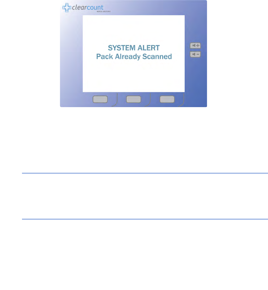
Figure 4-1 Example System Alert Message Screen
Pack Not Verified - Retry Pack
Discard Pack
CAUSE:
The system is unable to scan the sponge
pack.
ACTION:
Flip or rotate sponges and rescan the pack. If rescanning
does not correct the condition, discard the pack and
resume scanning a new pack.
CAUSE:
The system has detected a problem with the
sponge pack.
ACTION:
Discard the sponge pack and resume scanning with a
new pack.

4-5
Chapter 4: Troubleshooting
-
System Alerts
•
•
•
•
•
•
Multiple Packs Detected - Remove and Scan One Pack at a Time
Pack Already Scanned
Change Bag - Bucket Limit Has Been Exceeded - Remove Sponges to Continue
Bag Overflow Warning - Bucket Limit Has Been Exceeded - Remove Sponges to Continue
Wand Disconnected
CAUSE:
The system is unable to scan in multiple packs
at the same time.
ACTION:
Ensure that only one pack of sponges is being placed on
the In-Scan Tray at a time.
CAUSE:
The sponge pack has already been counted.
ACTION:
The sponge pack is ready for use - continue with system
setup or operation.
CAUSE:
There are over
50
sponges in the Count Out
Bucket.
ACTION:
Remove sponges or discard the full bag and replace with
a new liner - sponge counts will not change.
CAUSE:
There are over
70
sponges in the Count Out
Bucket.
ACTION:
Remove sponges or discard the full bag and replace with
a new liner - sponge counts will not change. Alert will
remain until less than
70
sponges are present in the
Count Out Bucket.
CAUSE:
The SmartWand is not connected.
ACTION:
Ensure that the SmartWand is properly plugged into the
system.
Chapter 4: Troubleshooting - System Warnings 4-6
•
•
•
•
•
•
System Warnings
System Warnings are serious conditions that have been caused by misuse of the SmartSponge System. To
correct a system warning condition, remove the full bag of sponges, place a new liner on the Count Out Bucket,
and power cycle the system.
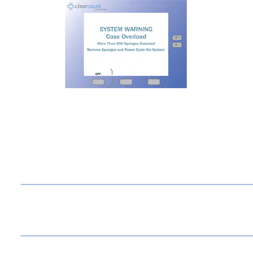
Figure 4-2 Example Warning Message Screen
System Reset - Bucket Limit Has Been Exceeded - Remove Sponges and Power Cycle the
System
Case Overload - More Than 500 Sponges Detected - Remove Sponges and Power Cycle the
System
CAUSE:
There are
80
or more sponges in the Count Out
Bucket.
ACTION:
Remove sponges and separate into groups of no more
than
50
- Power cycle the system and then reinsert the
groups into the Count Out Bucket one group at a time to
assure all sponges have been accounted for. The system
suspends counting while in this warning state. To assure
accurate counting, there should never be more than
50
sponges in the Count Out Bucked at a time.
CAUSE:
The overall sponge count limit for the surgery
has been exceeded.
ACTION:
Manually count used sponges.
4-7
Chapter 4: Troubleshooting
-
System Failure
•
•
•
•
•
•
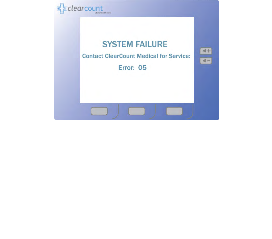
System Failure
A system failure is a serious condition that will cause the SmartSponge System to stop working.
If you receive a system failure message:
•
Contact ClearCount Medical Solutions for service,
•
Provide service with the numeric error code, and
•
Power down the system.
The system should not be used again until it has been serviced.
Figure 4-3 Example System Failure Screen
For additional information please call customer service at
(888) 931-0787
A-1
•
•
•
•
•
•
• • • • • •
Appendix A: Technical Specifications
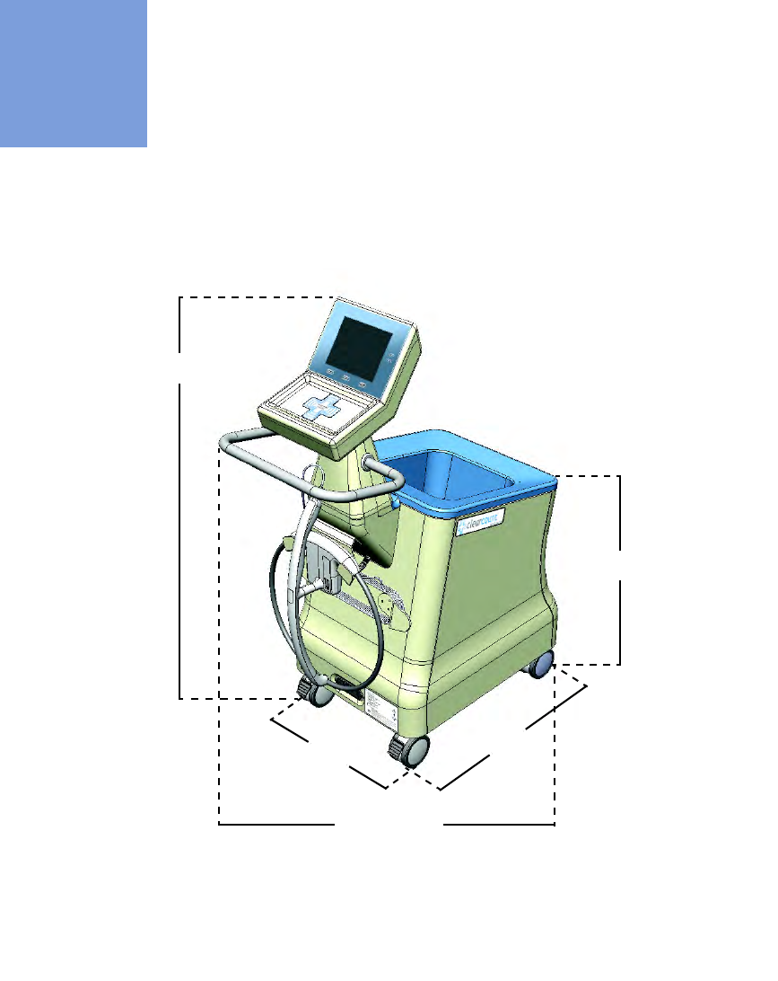
SmartSponge® System Dimensions
Figure A-1 SmartSponge System - Model A02
Weight - 96 lbs (44 kg)
48” (122 cm)
26” (66 cm)
34” (86 cm)
20” (51 cm) 25” (64 cm)

A-2 Appendix A: Technical Specifications
-
Power Requirements
•
•
•
•
•
•
Power Requirements
Environmental Conditions
SmartSponge System Sponges and Towels
•
All SmartSponge Sponges and Towels are constructed of 100% cotton.
•
ClearCount RFID tags are encapsulated in bio-compatible epoxy.
Power supply: 120 - 240 VAC, 50/60 Hz, 60 W
Power consumption: 0.65 Amps at 120 VAC
Outlet requirement: standard, single-phase, grounded three-prong outlet
Power cord length: 20 feet
Internal fuse rating: 3 Amp, fast acting on Neutral (N) and Line (L)
Operating Temperatures:
Ambient temperature: 50°F to 104°F (+10°C to +40°C)
Relative humidity 30 to 75%
Atmospheric pressure 700 to 1060 hPa
Transport and Storage Temperatures:
Ambient temperature: -40°F to 158°F (-40°C to +70°C)
Relative humidity: 10 to 95% noncondensing
Atmospheric pressure: 500 to 1060 hPa

Appendix A: Technical Specifications - EMC Considerations A-3
•
•
•
•
•
•
EMC Considerations
The ClearCount SmartSponge System needs special precautions regarding Electromagnetic Compatibility
(EMC), and must be installed and put into service according to the EMC information provided in this manual.
Portable and mobile RF equipment can affect the ClearCount SmartSponge System.
Compatibility of cables, transducers, and other accessories: Not applicable.
Guidance and Manufacturer’s Declaration – Emissions
All Equipment and Systems
Guidance and Manufacturer’s Declaration - Emissions
The ClearCount SmartSponge System Model A02 is intended for use in the electromagnetic environment
specified below. The customer or user of the ClearCount SmartSponge System Model A02 should ensure that
it is used in such an environment.
Emissions Test Compliance Electromagnetic Environment – Guidance
RF Emissions
CISPR 11
Group 2 The ClearCount SmartSponge System Model A02 must emit
electromagnetic energy in order to perform its intended
function. Nearby electronic equipment may be affected.
RF Emissions
CISPR 11
Class B The ClearCount SmartSponge System Model A02 is suitable
for use in all establishments, including domestic, and those
directly connected to the public low-voltage power supply
network that supplies buildings used for domestic purposes.
Harmonics
IEC 61000-3-2
Class A
Flicker
IEC 61000-3-3
Complies

A-4 Appendix A: Technical Specifications
-
EMC Considerations
•
•
•
•
•
•
Guidance and Manufacturer’s Declaration – Immunity
All Equipment and Systems
Guidance and Manufacturer’s Declaration – Immunity
The ClearCount SmartSponge System Model A02 is intended for use in the electromagnetic environment
specified below. The customer or user of the SmartSponge System Model A02 should ensure that it is used
in such an environment.
Immunity Test IEC 60601 Test
Level Compliance
Level Electromagnetic Environment –
Guidance
ESD
IEC 61000-4-2
±6kV Contact
±8kV Air
±6kV Contact
±8kV Air
Floors should be wood, concrete or
ceramic tile. If floors are synthetic, the r/h
should be at least 30%.
EFT
IEC 61000-4-4
±2kV Mains
±1kV I/Os
±2kV Mains
No I/Os
Main power quality should be that of a
typical commercial or hospital
environment.
Surge
IEC 61000-4-5
±1kV Differential
±2kV Common
±1kV Differential
±2kV Common
Main power quality should be that of a
typical commercial or hospital
environment.
Voltage Dips/Dropout
IEC 61000-4-11
>95% Dip for 0.5
Cycle >95% Dip for
0.5 Cycle
Main power quality should be that of a
typical commercial or hospital
environment. If the user of the ClearCount
SmartSponge System Model A02 requires
continued operation during power mains
interruptions, it is recommended that the
ClearCount SmartSponge System Model
A02 be powered from a power source that
has automatic emergency backup.
60% Dip for
5 Cycles
60% Dip for
5 Cycles
30% Dip for
25 Cycles
30% Dip for
25 Cycles
>95% Dip for
5 Seconds
>95% Dip for
5 Seconds
Power Frequency
50/60Hz
Magnetic Field
IEC 61000-4-8
3 A/m 3 A/m Power frequency magnetic fields should
be that of a typical commercial or hospital
environment.
Appendix A: Technical Specifications - EMC Considerations A-5
•
•
•
•
•
•
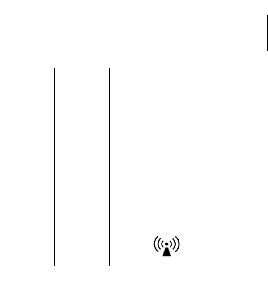
Guidance and Manufacturer’s Declaration – Emissions
Equipment and Systems that are NOT Life-supporting
Guidance and Manufacturer’s Declaration – Emissions
The ClearCount SmartSponge System Model A02 is intended for use in the electromagnetic environment
specified below. The customer or user of the ClearCount SmartSponge System Model A02 should ensure that
it is used in such an environment.
Immunity Test IEC 60601 Test
Level Compliance
Level Electromagnetic Environment – Guidance
Conducted RF
IEC 61000-4-6
Radiated RF
IEC 61000-4-3
3 Vrms
150 kHz to 80 MHz
3 V/m
80 MHz to 2.5 GHz
3Vrms
3V/m
Portable and mobile communications equipment
should be separated from the ClearCount
SmartSponge System Model A02 by no less than
the distances calculated/listed below:
D=(3.5/3)(Sqrt P)
D=(3.5/3)(Sqrt P)
80 to 800 MHz
D=(7/3)(Sqrt P)
800 MHz to 2.5 GHz
where P is the max power in watts and D is the
recommended separation distance in meters.
Field strengths from fixed RF transmitters, as
determined by an electromagnetic site survey
a
,
should be less than the compliance level in each
frequency range
b
.
Interference may occur in the
vicinity of equipment marked
with the following symbol:
.

A-6 Appendix A: Technical Specifications
-
EMC Considerations
•
•
•
•
•
•
NOTE 1 At 80 MHz and 800 MHz, the higher frequency range applies.
NOTE 2 These guidelines may not apply in all situations. Electromagnetic propagation is affected by
absorption and reflection from structures, objects and people.
Field strengths from fixed transmitters, such as base stations for radio (cellular/cordless) telephones and land
mobile radios, amateur radio, AM and FM radio broadcast and TV broadcast cannot be predicted
theoretically with accuracy. To assess the electromagnetic environment due to fixed RF transmitters, an
electromagnetic site survey should be considered. If the measured field strength in the location in which the
ClearCount SmartSponge System Model A02 is used exceeds the applicable RF compliance level above, the
ClearCount SmartSponge System Model A02 should be observed to verify normal operation. If abnormal
performance is observed, additional measures may be necessary, such as re-orienting or relocating the
ClearCount SmartSponge System Model A02.
Over the frequency range 150 kHz to 80 MHz, field strengths should be less than 3 V/m.
NOTE: This equipment has been tested and found to comply with the limits for a Class A digital device,
pursuant to part 15 of the FCC rules. These limits are designed to provide reasonable protection against
harmful interference when the equipment is operated in a commercial environment. This equipment
generates, uses, and can radiate radio frequency energy and, if not installed and used in accordance with the
instruction manual, may cause harmful interference to radio communications. Operation of this equipment in
a residential area is likely to cause harmful interference in which case the user will be required to correct the
interference at his own expense.

Appendix A: Technical Specifications - EMC Considerations A-7
•
•
•
•
•
•
Recommended Separation Distances between portable and mobile RF Communications equipment and the
ClearCount SmartSponge System Model A02
Equipment and Systems that are NOT Life-supporting
The SmartSponge System contains a receiver operating at a frequency of 13.56 MHz +/- 7 kHz.
The SmartSponge System may be interfered with by other equipment, even if that other equipment complies
with CISPR EMISSION requirements. If abnormal behavior is observed, please refer to the separation distance
chart provided in this appendix.
The SmartSponge system contains a transmitter operating at a frequency of 13.56 MHz, using 10% amplitude
shift keying at a modulation frequency of 423.75 kHz, and maximum effective radiated power of 200 mW.
Recommended Separations Distances for the
SmartSponge System Model A02
The ClearCount SmartSponge System Model A02 is intended for use in the electromagnetic environment in
which radiated disturbances are controlled. The customer or user of the ClearCount SmartSponge System
Model A02 can help prevent electromagnetic interference by maintaining a minimum distance between
portable and mobile RF Communications Equipment and the ClearCount SmartSponge System Model A02
as recommended below, according to the maximum output power of the communications equipment.
Max Output Power
(Watts)
Separation (m)
150 kHz to 80MHz
D=(3.5/3)(Sqrt P)
Separation (m)
80 to 800MHz
D=(3.5/3)(Sqrt P)
Separation (m)
800MHz to 2.5GHz
D=(7/3)(Sqrt P)
0.01 .1166 .1166 .2333
0.1 .3689 .3689 .7378
1 1.1666 1.1666 2.3333
10 3.6893 3.6893 7.3786
100 11.6666 11.6666 23.3333
For transmitters rated at a maximum output power not listed above, the recommended separation distance
d
in meters (m) can be determined using the equation applicable to the frequency of the transmitter, where
P
is
the maximum output power rating of the transmitter in watts (W) according to the transmitter manufacturer.
NOTE 1 At 80 MHz and 800 MHz, the separation distance for the higher frequency range applies.
NOTE 2 These guidelines may not apply in all situations. Electromagnetic propagation is affected by
absorption and reflection from structures, objects and people.
A-8 Appendix A: Technical Specifications
-
Device Label
•
•
•
•
•
•
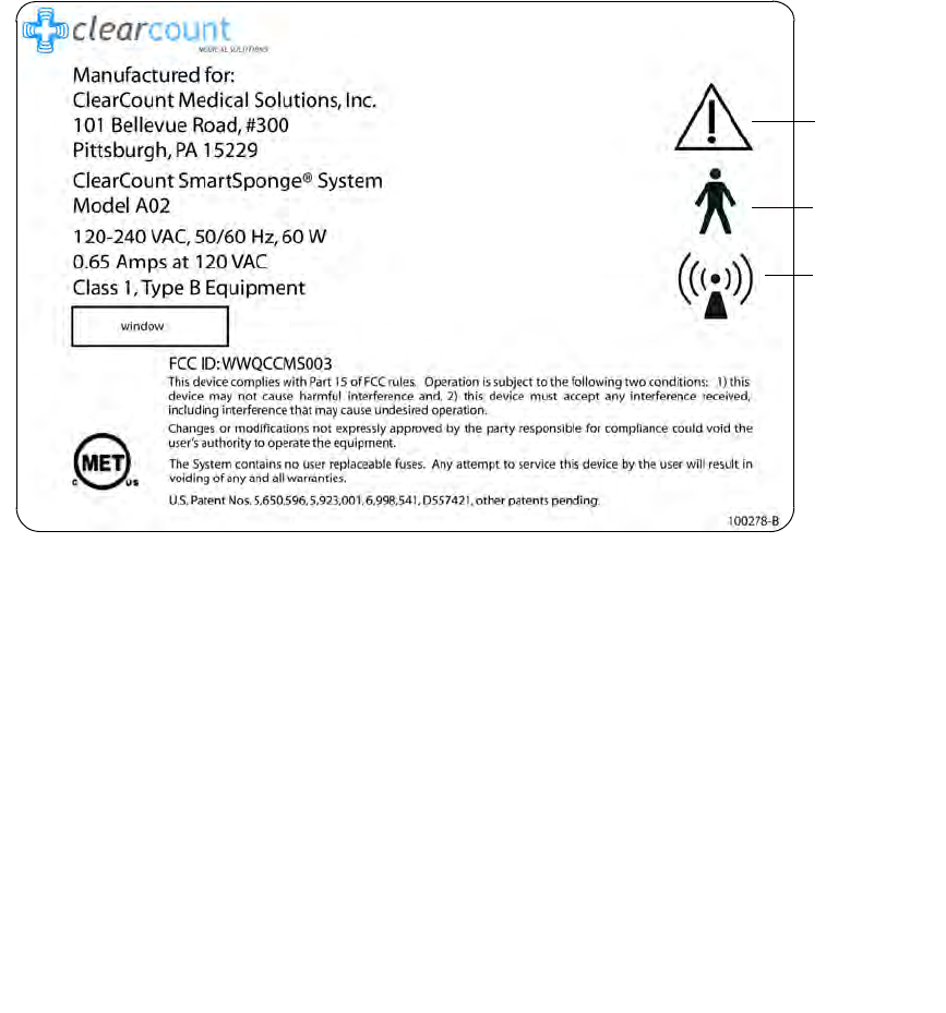
Device Label
Figure A-2 Device Label
Read
instructions
prior to use
Type B
equipment
Non-ionizing
radiation
c