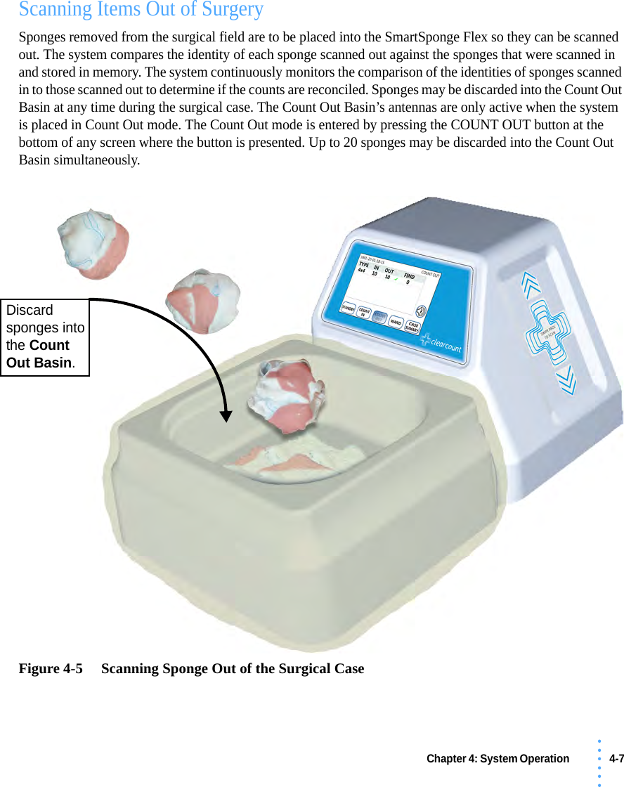
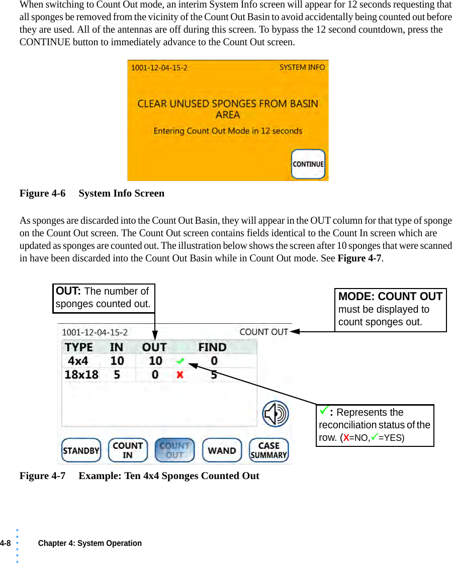
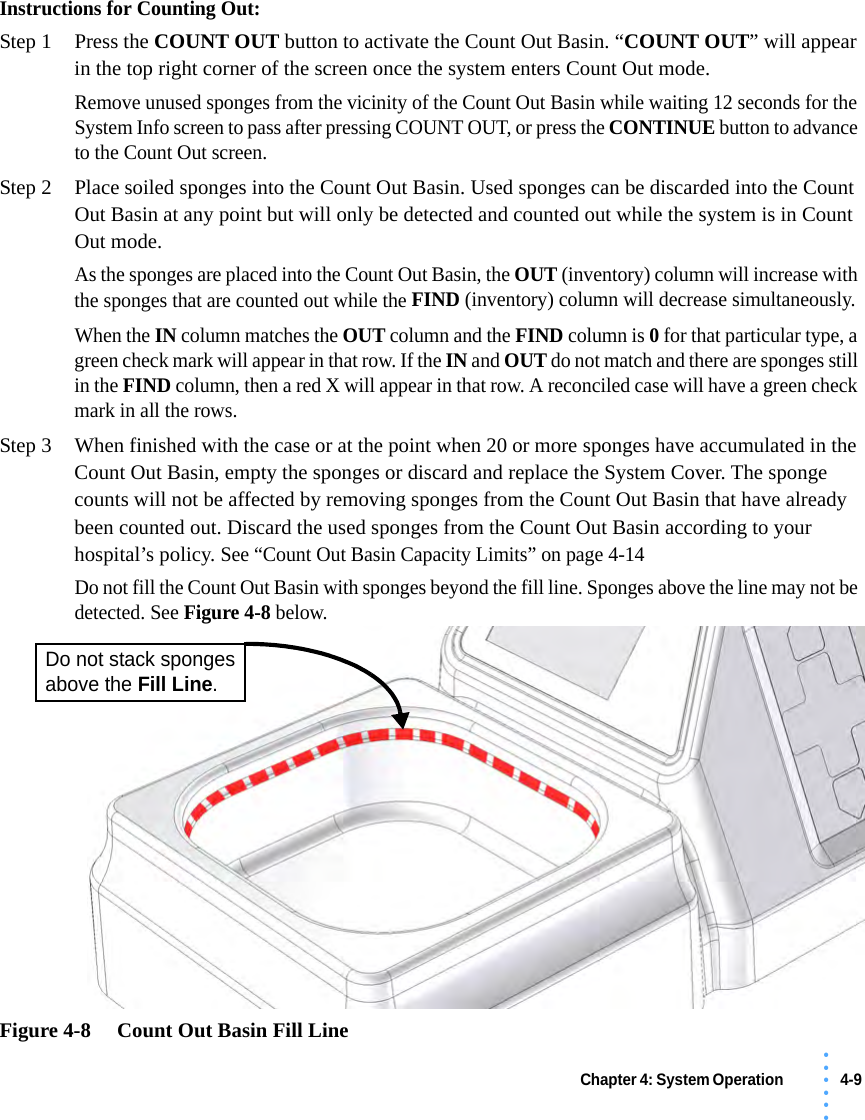
ClearCount Medical Solutions CCMS004 SmartSponge Flex Model A04 User Manual LCCD System Manual

ClearCount Medical Solutions Inc. SmartSponge Flex Model A04 LCCD System Manual

User Manual

i• • • •••• • • • • • PrefaceIndications for UseThe ClearCount Medical Solutions SmartSponge® Basin is indicated for use in counting and recording the number of RFID-tagged surgical gauze, laparotomy sponges, and towels used during surgical procedures. It also provides a non-invasive means of locating retained radio-frequency identification (RFID)-tagged surgical sponges, towels, and other tagged items within a surgical site. WarningsThe following list of warnings applies to the SmartSponge Flex:•Use only one SmartSponge Flex during a surgical procedure.•Do not dispose of sponges from a previous surgical case into the Count Out Basin. Sponge counts may not reconcile properly. Use only sponges from the current surgery.•Do not use the system in the presence of a flammable anesthetic mixture with air, or with oxygen or nitrous oxide.•For the system to function, use only ClearCount disposables.•Keep the SmartSponge Flex outside of the sterile field, unless it is properly covered.•Place only ClearCount disposables in the Count Out Basin.•The sterility of disposables is guaranteed only for unopened, undamaged packs. Disposables are for single use only; do not re-use or re-sterilize disposables.•Do not cut or tear ClearCount disposables, as the RFID tags might become separated.•When scanning items contained in a sterile surgical kit (bundles of items not in their own sterile packs) into the SmartSponge Flex, cover the system with the sterilized liner from the surgical kit. This prevents contamination of the items being scanned.•Using the wand without a sterile wand cover could contaminate the sterile field.•Holding items that have been scanned in too close to the Count Out Basin may result in these items being added to the Out column of the inventory (detected) prior to use and disposal. Dispose of any items into the Count Out Basin without using them if they have been counted out prior to use.•Disposables should not be left inside the patient's body for more than 24 hours.
ii • • • ••••When using the wand, the system may experience a slight degradation of read range of RFID tagged items when metal objects are within the scanning field. Small metal objects like implants and pacemakers will have no impact in most cases. To the extent possible, remove metal from the scanning site or keep the RFID tags at least ½ an inch from direct contact with metal objects.•Individual sponges or packs of sponges may not correctly count when placed directly on metal surfaces including back tables, mayo stands, large reusable capacitively-coupled return electrode pads and metal kick buckets. When using the wand, remove the sponges from those areas, or provide a separation distance between the metal and the RFID tags so that the tags can be read.•When using a SmartTag in conjunction with a large reusable capactively-coupled return electrode pad, it is necessary to place the tag lateral to the pad in order for the wand to detect it. The SmartTag will not be detected if applied directly to the pad because of its metal interior.•While using the wand, interference may appear momentarily on ECG graphs. Users should be aware that this interference is temporary and will discontinue when the wand is moved away from ECG equipment or when wand use is discontinued. •While using the wand interference may appear on Ultrasound images. Place the device in Standby while ultrasound imaging is in progress. The device will not lose count when in Standby.•The wand is a tool to assist in the location of tagged items within the body. Use of the wand, does not guarantee that a tagged item will be detected. Detection depends on proper technique and a variety of environmental conditions. •The orientation of the RFID tags within a body has an effect on the ability to read those tags. For this reason, proper wand technique should be exercised when searching for tagged items. Proper technique requires deliberate and thorough scanning through various orientations. See Chapter 4 of this operators manuals for complete details. •Packs of sponges, either partial or complete, may not count when discarded into the Count Out Basin. If a pack is discarded and fails to read, separate the sponges from each other to ensure a correct count. •Tags may become damaged by surgical lasers. Do not apply a surgical laser directly to a tag. The loss of tag function may result.•Due to possible interference, the system should be separated by at least 1 meter from an active Electrosurgical Unit (ESU). The system should be checked for normal operation to ensure there is no interference present.•No part of the ClearCount SmartSponge Flex is user serviceable. The system contains no user replaceable fuses. All Service is to be performed by trained personnel. •Cardiac pacers should be set to asynchronous pacing (VOO/DOO) mode prior to patient scanning with the wand to avoid potential short-term interference.
iii• • • •••Conventions Used Warning! A warning is a statement that identifies conditions or actions that could result in personal injury or loss of life.  Caution! A caution is a statement that identifies conditions or actions that could result in damage to the system.  Notes A note is an advisory comment or recommendation regarding practices or procedures.
iv • • • •••
Table of Contents• • • •••Preface .............................................................................................................................................................iChapter 1: System Description .................................................................................................................. 1-1Counting System ...................................................................................................................... 1-3SmartWand .............................................................................................................................. 1-5Mobile Cart  .............................................................................................................................. 1-7Accessories .............................................................................................................................. 1-9Chapter 2: System Interface ....................................................................................................................... 2-1Boot-up Screens ....................................................................................................................... 2-2Case Selection Screen .............................................................................................................. 2-3Active-Case Screens  ................................................................................................................ 2-5Chapter 3: Preparing for a New Case  ........................................................................................................ 3-1Powering the SmartSponge® Flex ........................................................................................... 3-2Placing the SmartTag ............................................................................................................... 3-4Setting Up for Surgery ............................................................................................................. 3-5Chapter 4: System Operation ..................................................................................................................... 4-1Beginning a New Case ............................................................................................................. 4-2Scanning Items Into Surgery ....................................................................................................4-4Scanning Items Out of Surgery ................................................................................................ 4-7Scanning a Patient for Retained Items ................................................................................... 4-17Ending a Surgical Case  .......................................................................................................... 4-24Restoring Power ..................................................................................................................... 4-30Chapter 5: System Settings ........................................................................................................................ 5-1Edit Settings Mode.................................................................................................................... 5-2Edit Date/Time ......................................................................................................................... 5-3Adjust Screen Brightness ......................................................................................................... 5-4Adjust Screen Timeout  ............................................................................................................ 5-5Calibrate Screen ....................................................................................................................... 5-6Adjust Volume ......................................................................................................................... 5-7Chapter 6: Review Case Data .................................................................................................................... 6-1Review Case Data on the System ............................................................................................. 6-2Chapter 7: Cleaning and Maintenance ....................................................................................................... 7-1Cleaning Instructions   .............................................................................................................. 7-2Maintenance  ............................................................................................................................ 7-3
Table of Contents• • • •••Chapter 8: Troubleshooting  ....................................................................................................................... 8-1System Alerts  ........................................................................................................................... 8-2System Warnings ...................................................................................................................... 8-4System Failure .......................................................................................................................... 8-5General Troubleshooting .......................................................................................................... 8-6Appendix A: Technical Specifications ......................................................................................................A-1SmartSponge® Flex Dimensions ............................................................................................ A-1Power Requirements   .............................................................................................................. A-2Environmental Conditions .......................................................................................................A-2ClearCount Sponges and Towels  ............................................................................................ A-2MRI Information   .................................................................................................................... A-2EMC Considerations  ............................................................................................................... A-3Device Label  ........................................................................................................................... A-8
1-1• • • •••• • • • • • Chapter 1: System DescriptionThe SmartSponge® Flex is used in an operating room to detect and identify tagged surgical items for the purpose of reconciling surgical counts. It is intended to be used as an adjunct to count policy and procedure based on AORN Recommended Practices. The system employs radio-frequency identification (RFID) technology to detect ClearCount SmartSponge surgical gauze, sponges, and towels. The system combines the benefits of counting and detection of surgical items (gauze, sponges, and towels) used during a surgical case. It has a user-friendly color touch screen display that provides detailed item counts along with audible notification. The counts are automatically updated as SmartSponge RFID-tagged sponges and towels are scanned “in” and counted “out” of the surgical procedure. This chapter includes a brief overview of the system and a detailed description of its components.
1-2 Chapter 1: System Description - • • • •••SmartSponge Flex SystemSmartWandCounting SystemMobile CartAccessories
Chapter 1: System Description - Counting System 1-3• • • •••Counting SystemThe SmartSponge Flex utilizes surgical gauze, sponges, and towels that have been “tagged” with an RFID tag. This RFID tag is about the size of a typical medicine capsule and does not contain a battery. Because each sponge contains a tag with unique identification, the system can quickly and accurately count and identify each sponge. See Figure 1-1 for the location of the components and Table 1-1 for the description.Figure 1-1     Counting System ComponentsDisplayCount Out BasinIn ScannerPower CordData PortsON BACK
1-4 Chapter 1: System Description - Counting System• • • •••Table 1-1 Counting System ComponentsComponent DescriptionDisplay A touch screen that displays information for the user and provides an interface for operating the system.In Scanner The area on which sponge and towel packs are to be swiped when scanning them into a surgical case.Count Out Basin Receptacle to contain the discarded sponges and towels after their use in surgery that also counts the items out of the case.Power Entry and On/Off Switch Connects the system to the power source via the power cable. The On/Off switch toggles the power to the system.Data Ports Used by service personnel to diagnose and service the system.Power Cord Supplies power to the system from a wall outlet.
Chapter 1: System Description - SmartWand 1-5• • • •••SmartWandThe SmartWand is used for detecting RFID-tagged ClearCount items. The wand can quickly identify tagged items in and around the patient during a surgical procedure. See Figure 1-2 for the location of the components and Table 1-2 for the description.Figure 1-2     SmartWand ComponentsBi-Color LEDSingle Color LEDWand HandleWand CordWand Connector
1-6 Chapter 1: System Description - SmartWand• • • •••Table 1-2 SmartWand ComponentsComponent DescriptionWand Handle  Used to hold the SmartWand while the wand is in use. Bi-Color LED Changes with the wand’s detection status. Off - Nothing detectedSolid Blue - SmartTag detected Solid Amber - SmartSponge being detectedSingle-Color LED Changes with the wand’s status.Solid Green - Wand attached and poweredOff - Wand not attached or not poweredWand Cord Provides power and communications to the SmartWand from the SmartSponge Flex.Wand Connector BNC connector used to connect the wand’s cord to the SmartSponge Flex.
Chapter 1: System Description - Mobile Cart 1-7• • • •••Mobile CartThe Mobile Cart mounts the Counting System and SmartWand. It also manages the system’s power and wand cables.See Figure 1-3 for the location of the components and Table 1-3 for the description.Figure 1-3     Mobile Cart ComponentsCable ManagementSystem MountLocking CastersWand HangerPower Cord WrapWand Cord Hanger
1-8 Chapter 1: System Description - Mobile Cart• • • •••Table 1-3 Mobile Cart ComponentsComponent DescriptionSystem Mount The plate at the top of the cart used to secure the SmartSponge Flex to the cart.Cable Management A series of cable hooks used to route and secure the power and wand cords.Wand Cord Hanger Used to retain the wand’s cord while the wand is being stored on the cart.Wand Hanger Holds the SmartWand when not in use.Power Cord Wrap Used to retain any excess power cord while the system is in use or being transported.Locking Casters Two of the five casters at the bottom of the cart have a foot switch to lock them in place. Used to secure the position of the system.
Chapter 1: System Description - Accessories 1-9• • • •••AccessoriesAdditionally, the SmartSponge Flex relies on several accessories for proper use and patient care. These accessories are described as follows.See Figure 1-4 for an example of the accessories and Table 1-4 for the description.
1-10 Chapter 1: System Description - Accessories• • • •••Figure 1-4     AccessoriesSurgical KitSterile PacksSmartTag SmartTag SpecialOverride CardWand CoverSystem Cover
Chapter 1: System Description - Accessories 1-11• • • •••Table 1-4 ClearCount Disposables and AccessoriesAccessory DescriptionSterile Packs Individual sterile packs of surgical sponges tagged with ClearCount RFID tags.Surgical Kits A pre-packaged sterile kit of materials and equipment assembled for a specific surgery. Included are various banded packs of SmartSponges for use with the SmartSponge Flex.SmartTags An adhesive backed RFID tag applied between the sheets of the OR table prior to surgery, which allows the user to ensure that the SmartWand is operational. (SmartTag Special is for use with carbon fiber top OR tables only)Override Card A Smart Card used by the authorized staff member to enable an un-reconciled case to be closed and to access the system settings menu. Wand Cover A large, sterile, clear plastic sheath used to protect the sterile field when using the SmartWand. The sheath covers the wand and a portion of the wand cord.System Cover A large plastic bag used to protect the system and basin from contamination as soiled sponges are discarded. Sterile when provided in surgical kits.
1-12 Chapter 1: System Description - Accessories• • • •••
2-1• • • •••• • • • • • Chapter 2: System InterfaceThis chapter presents an overview of the various screens, and navigation features for the SmartSponge Flex. These include the following:•Boot Up Screens•Splash Screen•Self Diagnostics Screen•Case Selection Screen•Past Cases•New Case•Settings Screen•Volume Screen•Active-Case Screens•Standby Screen•Count In Screen•Count Out Screen•Wand Screen•Case Summary Screen
2-2 Chapter 2: System Interface - Boot Up Screens• • • •••Boot Up ScreensThese screens appear for brief periods when the system is powered on. Splash ScreenThe Splash screen is the first thing displayed when the system is powered on. It will appear for a few seconds.Figure 2-1     Splash ScreenSelf Diagnostics ScreenThe Self Diagnostics screen follows the Splash screen when the system boots up. The system displays this screen while key components are checked. Their status is displayed on the screen. The system’s firmware version and device ID are also displayed on this screen. This screen is displayed for about a minute and the remaining time is illustrated by the progress bar at the top.Figure 2-2     Self Diagnostics Screen
Chapter 2: System Interface - Case Selection Screen 2-3 • • • •••Case Selection ScreenThe Case Selection screen will be displayed after the self diagnostics have finished. From this screen, you have the option to start a new surgical case, review past case data, edit the system settings, or adjust the system volume. These features are described below:Figure 2-3     Case Selection ScreenPAST CASESPressing the PAST CASES button from the Case Selection screen will display the Case Review screen. From this screen you have the option to select from past cases and review the data. Pressing the BACK button returns to the Case Selection screen.Refer to Chapter 6 for a description of reviewing case data.NEW CASEPressing the NEW CASE button from the Case Selection screen initiates a new surgical case. Refer to Chapter 4 for a description of starting a new case.VOLUME ICONSETTINGS ICON
2-4 Chapter 2: System Interface - Case Selection Screen• • • •••SETTINGS ScreenThe Settings screen appears after pressing the settings icon from the Case Selection screen. From this screen, you have the option to select from a list of adjustable settings. When finished, press the BACK button to return to the Case Selection screen.Refer to Chapter 5 for a description of editing the system’s settings. Figure 2-4     Settings ScreenVOLUME ScreenThe Volume screen appears after pressing the volume icon from the Case Selection screen. From this screen, you have the ability to adjust the system volume. The system volume has a range from 0 (off) to 10 (loudest). When finished press the BACK button to return to the Case Selection screen.Refer to Chapter 5 for a description of adjusting the system’s volume. Figure 2-5     Volume Screen
Chapter 2: System Interface - Active-Case Screens 2-5 • • • •••Active-Case ScreensActive-Case screens are present during a surgical case. They are initiated after pressing the NEW CASE button from the Case Selection screen.When in an active surgical case, the current case number is displayed in the upper left corner of the screen and the current mode is displayed in the upper right corner of the screen.The Case Number follows a format of:Five navigation buttons are presented at the bottom of the screen that allow you to switch between modes. These modes are Standby, Count In, Count Out, Wand and Case Summary. Each mode is briefly described below.Figure 2-6     Example of an Active Surgical Case ScreenDevice ID XXXX-YY-MM-DD-ZZZYear Month Day Case#Mode of OperationCase NumberNavigation Buttons
2-6 Chapter 2: System Interface - Active-Case Screens• • • •••Standby ScreenThe system defaults to Standby mode when a new surgical case is started and the Standby screen is displayed. All antennas are off while in Standby. The system will not count sponges into or out of the surgical case while in Standby. The purpose of Standby is to allow the system to stay inactive while not in use. You can switch to any other mode from the Standby screen with the navigation buttons along the bottom of the screen.Refer to page 4-3 for a description of Standby mode. Figure 2-7     Standby ScreenCount In ScreenThe Count In screen is displayed while in Count In mode. Count In mode is used for scanning packs of sponges into the surgical case. The In Scanner’s antenna actively looks for sponge packs while in Count In mode. Sponge packs that are swiped across the In Scanner will be added to the In column of the onscreen sponge counts. Both the wand and basin antennas are off during Count In modeRefer to page 4-4 for a description of Count In mode. Figure 2-8     Count In ScreenIn the example to the left, a pack of 518x18 lap sponges has been scannedin. This adds 5 sponges to the IN andFIND columns. IN represents the total ofthat type and FIND represents howmany of that type are still in use.
Chapter 2: System Interface - Active-Case Screens 2-7 • • • •••Count Out ScreenThe Count Out screen is displayed while in Count Out mode. Count Out mode is used for scanning sponges out of the surgical case that are discarded into the Count Out Basin. The Count Out Basin’s antennas are only active while in Count Out mode. Sponges that are scanned out will increase the Out column of the onscreen sponge counts and the Find column will subsequently decrease. Refer to page 4-7 for a description of Count Out mode. Figure 2-9     Count Out ScreenWand ScreenThe Wand screen is displayed while in Wand mode. Wand mode is used for detecting sponges with the SmartWand. Detected sponges will be displayed in the “FOUND” column onscreen. These detected sponges are not counted into or out of the surgical case. The SmartWand is also used to scan a SmartTag if you have placed one underneath the patient before the surgery. The detection status of the SmartTag is displayed on the Wand screen. You’re also able to press the HELP icon in the bottom right of the screen for an illustration that describes the patient scanning procedure.Refer to page 4-17 for a description of Wand mode. Figure 2-10     Wand ScreenIn the example to the left, 3 18x18 lapsponges have been scanned out by theCount Out Basin while in Count Outmode. This adds 3 sponges to the OUTcolumn and subtracts 3 from the FINDcolumn. OUT represents the total of thattype that have been counted out.The RESET button clearsall of the detected itemsfrom the screen (includingthe SmartTag).The HELP icon brings upthe Wand Help screen
2-8 Chapter 2: System Interface - Active-Case Screens• • • •••Case Summary ScreenThe Case Summary screen is displayed while in Case Summary mode. Case Summary displays information about the current case and sponge counts at the time Case Summary is entered. Press the CASE SUMMARY button at the bottom right corner of the screen to enter the Case Summary. From this screen, you can close out a reconciled case by pressing END CASE or override an unreconciled case with an Override Card by pressing OVERRIDE. You may also navigate back to the previous mode by pressing the BACK button. All antennas are off while in the Case Summary. Refer to page 4-24 for a description of Case Summary. Figure 2-11     Case Summary ScreenThe END CASE button will be presented if the sponge counts are reconciled.Pressing it ends the case. The OVERRIDE button will be presented if the countsare not reconciled. Pressing it brings up the Override screen for scanning anOverride Card and ending a case with unreconciled counts.The Count Status will display “COUNTSEQUAL” if all sponges are reconciled. If anyare missing when Case Summary is entered,“COUNTS NOT EQUAL” will be displayed.
3-1• • • •••• • • • • • Chapter 3: Preparing for a New CaseChapter 3 describes the initializing the SmartSponge Flex for a new case. This includes the following topics:•Powering the SmartSponge Flex•Boot-Up Sequence•Placing the SmartTag•Setting Up for Surgery•Using Pre-Packaged Sterile Surgical Kits•Using Individual Sterile Sponge Packs
3-2 Chapter 3: Preparing for a New Case • • • •••Powering the SmartSponge FlexThe following procedure describes how to set up the SmartSponge Flex before each surgical case. Place the SmartSponge Flex in the desired position in the Operating Room (OR) and lock the two locking casters at the base of the cart. Step 1 Connect the system to a grounded, power outlet using the power cord supplied.Step 2 Check that the other end of the power cord is securely plugged into the power entry module of the system.Step 3 Set the power ( | / O ) switch shown in Figure 3-1 below to the On ( | ) position. There will be an audible tune and splash screen that briefly appears on the display after the switch is flipped.Figure 3-1     Location of On/Off SwitchWarning! Inspect the power cord prior to each use, and replace it if damaged. A frayed or worn cord presents an electrical shock hazard that may result in personal injury or death.
Chapter 3: Preparing for a New Case  3-3 • • • •••Boot-Up SequenceThe Splash screen, shown at the top left of Figure 3-2, appears on the display first for a few seconds after the On/Off switch is set to On.The Self Diagnostic screen, shown at the bottom right of Figure 3-2, is displayed for about a minute directly after the Splash screen and shows a Progress Bar that fills in from left to right. The screen shows the versions of system firmware, device ID, and system time. Functional status is also checked during this self test and the results are displayed. When complete, the system enters the Case Selection screen. Figure 3-2     Boot-Up ScreensThe Case Selection screen is displayed after the system successfully completes the self diagnostic checks. Press NEW CASE to begin a new surgical case.Splash ScreenDiagnostic Screen
3-4 Chapter 3: Preparing for a New Case • • • •••Placing the SmartTagBefore the start of a surgery, place a SmartTag between the surgical sheets under the patient. The standard SmartTag is to be used on phenolic top OR tables while the SmartTag Special is for use with carbon fiber top OR tables. Figure 3-3 shows a SmartTag and its typical placement. The SmartTag is an adhesive sticker that contains a radio-frequency identification (RFID) tag. This tag provides feedback to the SmartSponge Flex that the SmartWand is reading through the depth of the patient when a scan is performed. During pre-surgery setup, proceed to place the SmartTag as follows:Step 1 Peel the backing from the SmartTag.Step 2 Position the SmartTag below the surgical site and apply between the bottom sheet and the draw sheet.Step 3 Place the tag adhesive-side down.Figure 3-3     SmartTag PlacementNotes •If the wrong SmartTag is used on the wrong type of table, it will perform improperly. •Do not reuse SmartTags after they’ve been applied to the OR table sheets. SmartTags are a disposable one-time-use item. Warning!•The SmartTag is not approved for application to the patient’s skin.•The SmartTag will not be detected if applied directly to a large reusable capacitively-coupled return electrode pad because of its metal interior. Place the tag lateral to the pad in order for the wand to detect it.
Chapter 3: Preparing for a New Case  3-5 • • • •••Setting Up for SurgeryWith the system in position, and the SmartTag placed between the sheets on the OR table, you are ready to prepare the sponges and other supplies necessary for surgery. ClearCount sponges must be used with the SmartSponge Flex. These may either be packs of ClearCount sterile sponges, or ClearCount sponges supplied in sterile surgical kits. The procedure for using one type versus the other is slightly different, as noted below.Using Pre-Packaged Sterile Surgical KitsStep 1 Locate and open the surgical kit. Using sterile technique, locate the following components:•System Cover•Wand Cover - this should be set aside within the sterile field in case the patient is scanned for sponges with the SmartWand.•Surgical sponges and towels - these will be contained within a paper band. Banded sponges should be scanned in one bundle at a time. Do not remove the band until the bundle has been scanned in.Step 2 Move the system adjacent to the sterile field.Step 3 Using aseptic technique, cover the entire system with the System Cover. Make sure the entire system is completely covered. Proceed to scan sponges and towels into the surgical case.Step 4 After the sponges and towels have been scanned in, the system can be placed in the desired mode and location for continuing the case. Using Individual Sterile Sponge PacksStep 1 Locate the following items:•Initial sponges and towels that will be used in the surgical case•System Cover•Pre-packaged sterile wand cover - this will be used if the patient is scanned with the SmartWand.Step 2 Drape the System Cover over the SmartSponge Flex.Step 3 Scan in sponges and towels while still in their sterile packaging.Step 4 Continue by placing the system in the desired mode for continuing the case.Notes •If a bundle of sponges within the surgical kit is damaged or unable to be scanned into the surgical case, replace that bundle with a pack of sterile ClearCount sponges.
3-6 Chapter 3: Preparing for a New Case • • • •••
4-1• • • •••• • • • • • Chapter 4: System OperationChapter 4 explains operating the SmartSponge Flex by describing the following functions:•Beginning a Case•Standby Mode•Scanning Items Into Surgery•Scanning Items Out of Surgery•Pausing a Case•Scanning a Patient for Retained Items•Using the SmartWand•Detecting the SmartTag•Ending a Surgical Case•Counts Equal•Counts Not Equal•Restoring PowerWarning! •For the system to function, use only ClearCount disposables.•Do not place sponges from a previous surgical case into the Count Out Basin. This will cause the sponge counts not to reconcile properly.•Do not cut or tear SmartSponge disposables, as this may cause the RFID tags to become separated from the disposables.
4-2 Chapter 4: System Operation • • • •••The SmartSponge Flex is designed to assign a unique number, referred to as a Case ID, to a single session of counting RFID-tagged disposables that are used in a particular surgical case. This Chapter describes how to begin a case, proceed through a case, and end a case. Beginning a CaseThe system will perform a series of self checks and display a progress bar when power is applied. The system will enter the Case Selection mode after the self checks finish.From the Case Selection screen, select NEW CASE to begin a new case. The system will generate a unique case number and will display that number in the upper left corner of the screen as the Case ID. Figure 4-1     Beginning a New CasePress NEW CASEto start a new case.A unique CASE ID will be generated anddisplayed in the upper left for this case.
Chapter 4: System Operation  4-3 • • • •••Standby ModeThe SmartSponge Flex is designed to not perform any scanning function until you specifically select to do so. Therefore, the system will enter Standby mode when you select to begin a new case. While in Standby mode, all antennas are off. The system can remain in Standby mode for as long as necessary while you prepare for surgery. When you are ready, you can navigate to any of the following modes:•Count In - Activates the In Scanner for scanning SmartSponges into the case.•Count Out - Activates the Count Out Basin for counting SmartSponges out of the case.•Wand - Activates the SmartWand for detecting SmartSponges.•Case Summary - Shows the sponge counts and case information for the current surgical case.Figure 4-2     Standby Mode Screen
4-4 Chapter 4: System Operation • • • •••Scanning Items Into SurgerySponges are “scanned in” to a surgical case so that the “In” count can be later reconciled with the “Out” count at the end of the case. This is possible because the system preserves in memory the unique identity of each sponge scanned into the case. Before a pack is scanned in, the system instantly verifies functionality of each individual tag and that the quantity matches the expected quantity for the pack.Sponges may be added into the surgical case at any time by entering Count In mode. The Count In mode is entered by pressing the COUNT IN button at the bottom of any screen where the button is presented. The In Scanner’s antenna is only active when the system is in Count In mode. Scan in packs of sponges/towels by swiping them across the In Scanner. Scan packs one at a time. Keep other packs away from the pack you are currently scanning.Figure 4-3     Scanning Sponge Packs Into the Surgical CaseSwipe ONE PACK across the In Scanner.
Chapter 4: System Operation  4-5 • • • •••As packs of sponges are scanned in, they will appear on the Count In screen by type in the order in which they were presented. The Count In screen contains fields that are populated with data as packs are scanned in. These fields are illustrated in Figure 4-4.Figure 4-4     Example: 1 Pack of 4x4 Sponges Scanned InInstructions for Scanning In:Step 1 Assemble the packs of sponges/towels intended for the surgical case at a location near the SmartSponge Flex, but not on the device.Step 2 Press the COUNT IN button to activate the In Scanner; “COUNT IN” will appear in the top right corner of the screen. Step 3 Scan ONE pack of SmartSponge surgical sponges or towels at a time into the surgical case by swiping the pack flat across the In Scanner over the area marked “SWIPE PACK TO SCAN”. Move the pack back and forth across the In Scanner until an audible tone is heard, and the system adds the pack contents to the IN (inventory) column. If the system does not accept the pack, re-orient it and scan again.Step 4 Set the scanned in pack away from the system in the area where the packs are staged prior to opening the packs.Step 5 Repeat Step 3 for each pack of sponges or towels being entered into the surgical case.Step 6 After sponges are scanned in, they may be opened to the sterile field using standard sterile technique. ClearCount SmartSponges are to be used in the same manner as generic surgical sponges. TYPE: The sponge type scanned in.IN: The number of sponges scanned in.OUT: The number of sponges counted out.FIND: The number of sponges not reconciled.X: Represents the reconciliation status of the row. (X=NO,=YES)MODE: COUNT IN must be displayed to scan sponges in.
4-6 Chapter 4: System Operation • • • •••Warning! •Holding items that have not been scanned in too close to the Count Out Basin while in Count Out mode may result in the items unintentionally being detected prior to use. Follow the on screen prompts and decline acceptance if the sponges were inadvertently held too close to the Count Out Basin.•Holding items that have already been scanned in too close to the Count Out Basin while in Count Out mode may result in the items unintentionally being counted out prior to use. Dispose any items into the basin that have been scanned in and then counted out (detected) by the Count Out Basin. Notes •Make sure “COUNT IN” is displayed in the upper right of the display when scanning packs into the surgical case.•If two or more packs are detected by the In Scanner at the same time the system will display the “Multiple Packs Detected” alert. Remove the packs and re-scan one at a time. •If a pack that has already been scanned in is presented to the In Scanner to be scanned in again, the message “Pack Already Scanned” will appear. Open and use pack as per normal operation.•If the alert “Discard Pack” is displayed, throw out the defective pack and replace it with a new pack. •If after a pack is scanned, no tone is heard and zero sponges are added to the count, throw out the defective pack and replace it with a new pack.•Do not rest sponge packs or any other items on or near the In Scanner.
Chapter 4: System Operation  4-7 • • • •••Scanning Items Out of SurgerySponges removed from the surgical field are to be placed into the SmartSponge Flex so they can be scanned out. The system compares the identity of each sponge scanned out against the sponges that were scanned in and stored in memory. The system continuously monitors the comparison of the identities of sponges scanned in to those scanned out to determine if the counts are reconciled. Sponges may be discarded into the Count Out Basin at any time during the surgical case. The Count Out Basin’s antennas are only active when the system is placed in Count Out mode. The Count Out mode is entered by pressing the COUNT OUT button at the bottom of any screen where the button is presented. Up to 20 sponges may be discarded into the Count Out Basin simultaneously.Figure 4-5     Scanning Sponge Out of the Surgical CaseDiscard sponges into the Count Out Basin.
4-8 Chapter 4: System Operation • • • •••When switching to Count Out mode, an interim System Info screen will appear for 12 seconds requesting that all sponges be removed from the vicinity of the Count Out Basin to avoid accidentally being counted out before they are used. All of the antennas are off during this screen. To bypass the 12 second countdown, press the CONTINUE button to immediately advance to the Count Out screen.Figure 4-6     System Info ScreenAs sponges are discarded into the Count Out Basin, they will appear in the OUT column for that type of sponge on the Count Out screen. The Count Out screen contains fields identical to the Count In screen which are updated as sponges are counted out. The illustration below shows the screen after 10 sponges that were scanned in have been discarded into the Count Out Basin while in Count Out mode. See Figure 4-7. Figure 4-7     Example: Ten 4x4 Sponges Counted OutOUT: The number of sponges counted out.: Represents the reconciliation status of the row. (X=NO,=YES)MODE: COUNT OUT must be displayed to count sponges out.
Chapter 4: System Operation  4-9 • • • •••Instructions for Counting Out:Step 1 Press the COUNT OUT button to activate the Count Out Basin. “COUNT OUT” will appear in the top right corner of the screen once the system enters Count Out mode.Remove unused sponges from the vicinity of the Count Out Basin while waiting 12 seconds for the System Info screen to pass after pressing COUNT OUT, or press the CONTINUE button to advance to the Count Out screen.Step 2 Place soiled sponges into the Count Out Basin. Used sponges can be discarded into the Count Out Basin at any point but will only be detected and counted out while the system is in Count Out mode. As the sponges are placed into the Count Out Basin, the OUT (inventory) column will increase with the sponges that are counted out while the FIND (inventory) column will decrease simultaneously.When the IN column matches the OUT column and the FIND column is 0 for that particular type, a green check mark will appear in that row. If the IN and OUT do not match and there are sponges still in the FIND column, then a red X will appear in that row. A reconciled case will have a green check mark in all the rows.Step 3 When finished with the case or at the point when 20 or more sponges have accumulated in the Count Out Basin, empty the sponges or discard and replace the System Cover. The sponge counts will not be affected by removing sponges from the Count Out Basin that have already been counted out. Discard the used sponges from the Count Out Basin according to your hospital’s policy. See “Count Out Basin Capacity Limits” on page 4-14Do not fill the Count Out Basin with sponges beyond the fill line. Sponges above the line may not be detected. See Figure 4-8 below. Figure 4-8     Count Out Basin Fill LineDo not stack sponges above the Fill Line.
4-10 Chapter 4: System Operation • • • •••Warning! •Do not fill the Count Out Basin beyond its fill line. Items above the fill line may not be counted.•Packs of sponges, either partial or complete, may not be counted when discarded into the Count Out Basin. If a pack is discarded and the contents cannot be read, separate the sponges from each other to ensure a correct count. Notes •The Count Out Basin will not count items while the system is in COUNT IN mode. Likewise, the In Scanner will not scan items in while the system is in COUNT OUT mode.•Sponges contained within count bags or pocket-type devices may be discarded directly into the Count Out Basin.
Chapter 4: System Operation  4-11 • • • •••The SmartSponge Flex is designed on the premise that you will follow a standard practice of counting sponges prior to use and again after use to then reconcile those counts. It is recognized that there could be instances where, either intentionally or mistakenly, that sponges that have not been scanned into the case are presented to the Count Out Basin while in Count Out mode. This is referred to as Broken Protocol. Broken ProtocolThe Broken Protocol warning is triggered when a sponge(s) that has not been scanned into the case is detected by the Count Out Basin. While this may occur for good clinical reasons (i.e. emergency surgery without time to scan sponges in before use), it is not recommended procedure.Since the warning may be presented for different reasons, there are options to Decline the detected sponge, Accept it into the case, or switch to COUNT IN mode. See Figure 4-9. Figure 4-9     Broken Protocol Screen•DECLINEDeclining is the course to follow when a sponge(s) was mistakenly held too close to the Count Out Basin prior to being scanned in.Press DECLINE and the system will go back to the previous counts and continue. Before pressing DECLINE, be sure to remove the detected sponge(s) from the vicinity of the Count Out Basin or the system will continue to trigger the Broken Protocol warning.•ACCEPTAccepting is the proper action when a sponge(s) that was not scanned in was intentionally discarded into the Count Out Basin. This could be the result of an emergency situation where time did not allow for the sponges to first be scanned in before they were used.
4-12 Chapter 4: System Operation • • • •••Press ACCEPT and the system will prompt you to confirm your action to add the detected sponge (and the rest of the pack’s contents) into the surgical case’s counts and break protocol. Press ACCEPT again to confirm the action and all absent sponges from the same pack as the accepted sponge automatically become accepted into the case. The pack contents will be added to the IN column, with the detected sponge entered into the OUT column. The subsequent sponges from the pack will not need to be accepted; they will already exist in the FIND column. A message will then be displayed stating that protocol has been broken (this will not affect system performance or function). See Figure 4-10.•COUNT INIt is recognized that additional sponges may need to be added during a surgical case. It is possible that sponges brought to the SmartSponge Flex for the intention of scanning them into the case could first be detected by the Count Out Basin if the system is in Count Out mode. This will trigger the Broken Protocol Warning. In this instance, you should select to go to Count In mode. Pressing the COUNT IN button transitions the system into COUNT IN mode for scanning sponge packs into the case.Continue by following the instructions for Scanning Items Into Surgery. See page 4-4.Note •If you are unsure what to do when Broken Protocol is triggered, press DECLINE.
Chapter 4: System Operation  4-13 • • • •••Figure 4-10     Example: Accepting Broken ProtocolSponges from a pack of 4x4s not scanned in, is detected by the Count Out Basin.Confirm the action by pressing ACCEPT again or BACK to return to the previous screen.Broken Protocol is now displayed at the bottom of the screen. The Row of the sponges that were accepted will turn red.Press ACCEPT.
4-14 Chapter 4: System Operation • • • •••Figure 4-11     Example of Protocol Broken Note in Case SummaryThe TimeStamp for any Broken Protocols along with the Type of sponge triggering it, is displayed within the top section of the Case Summary.Broken Protocol is displayed at the bottom of the CASE SUMMARY screen. Listed under the Notifications within the bottom of the Case Summary is the user’s selected action to any Broken Protocol Warnings they received.
Chapter 4: System Operation  4-15 • • • •••Count Out Basin Capacity LimitsThe capacity of the Count Out Basin is limited to ensure optimal performance when counting out sponges that are discarded into it. There should never be more than 20 RFID-tagged sponges or towels in the Count Out Basin at the same time.•BASIN LIMIT REACHEDIf more than 20 sponges accumulate in the Count Out Basin simultaneously, the System Alert “BASIN LIMIT REACHED” will appear on the display. When this alert occurs, remove the sponges from the Count Out Basin, replace the System Cover (if necessary), and press CONTINUE to return to the Count Out screen. •BASIN LIMIT EXCEEDEDIf the “BASIN LIMIT REACHED” screen is ignored and the sponges accumulating in the Count Out Basin reaches 30, the System Warning “BASIN LIMIT EXCEEDED” will be displayed. The system will no longer count sponges in the Count Out Basin until less than 20 are present at a time. Remove the sponges, press CONTINUE to return to Count Out mode, and rescan the sponges from the Count Out Basin in groups of no more than 20 at a time. These measures are taken to assure accurate sponge counts. See Chapter 8 for explanations of System Alerts and Warnings.Figure 4-12     Basin Limit Alert and Warning ScreensNotes •Sponge Counts are not affected by removing already counted out sponges from the Count Out Basin.•The system will continue to count out sponges discarded into the Count Out Basin while on the System Alert screen.•Do not stack sponges in the Count Out Basin beyond the fill line.Notes •The system suspends all counting while on the System Warning screen. Rescan any sponges in the Count Out Basin in groups of less than 20 after pressing CONTINUE to ensure all sponges have been reconciled.
4-16 Chapter 4: System Operation • • • •••Pausing a CaseThere may be reasons you might want to pause the counting and detection functions of the system. The Standby mode is provided to allow you to pause a case. Placing the system into standby suspends all counting and detection functions by turning off all power to the system’s antennas. All count information is retained. You may resume the case by exiting Standby mode and entering the desired mode of operation.
Chapter 4: System Operation  4-17 • • • •••Scanning a Patient for Retained ItemsThe SmartWand allows you to scan patients for retained ClearCount sponges and towels at any point during surgery. Remove wand from holder then press the WAND button to enter Wand mode. It is important to note that an item found by the wand is not counted out. An item can only be counted out when it is presented to the Count Out Basin and the system is in Count Out mode. The SmartWand performs best when passed over the patient in a slow, steady fashion, no faster than 0.2 m/second (approximately 7 inches/second). Maintain a distance of 1 to 2 inches above the patient. While a tagged item may be found on the first pass of the wand, it is typical to make several passes at varying inclinations to locate an item within a body. On a typical patient, each scan pass should take approximately 5 seconds to complete. See Scanning Procedure. Figure 4-13     Wand Mode ScreenTo clear the detected sponges and SmartTag detection from the screen, press the RESET button. Press the WAND button from any mode to enter Wand Mode. When sponges are detected, they will be displayed by type and quantity.When the SmartTag is detected, the green check mark appears.SmartTag and 2 4x4 detected
4-18 Chapter 4: System Operation • • • •••Wand LED FunctionThe wand uses two LEDs and three colors to communicate status to the user. The combinations of colors result in four basic states, which are described below:Figure 4-14     Wand LED BehaviorBoth LEDs  Green LED Amber & Green Blue & Green When both LEDs are OFF, the wand is not active. (Wand is not active in any mode except Wand Mode.)When Wand Mode is entered the Green LED illuminates to show the wand is active. (If the Green LED is OFF, the wand is not attached or not powered. If the Bi-Color LED is OFF, no items have been detected; or the RESET button has been pressed.) The Green LED indicates the wand is active.The Blue LED will illuminate and stay on when a SmartTag is detected. When first detected, the system will produce an audible tone and change the detected status on the display to a green check mark. (The Amber LED will temporarily replace the Blue LED while a sponge is being detected. Once the wand no longer detects a sponge, it will revert back to Blue until the RESET button is pressed to clear the detected items.)The Green LED indicates the wand is active.The Amber LED illuminates when a sponge is being detected and an audible tone is produced. When the sponge leaves the wand’s detection field, the Amber LED turns OFF; or reverts back to Blue if a SmartTag has been detected.(The Amber LED is synchronized to the audible tone during sponge detection. This mimics the feedback of a metal detector passing over metal. The Amber LED and tone aid in locating sponges.)1) WAND OFFOFF2) WAND ONON3) SMARTTAG DETECTEDLEDs ON LEDs ON4) TAGGED ITEM DETECTED
Chapter 4: System Operation  4-19 • • • •••Patient Scanning ProcedureStep 1 Remove the SmartWand from the wand hanger on the mobile cart and free its cable from the cord wrap.Step 2 Cover the SmartWand with a sterile cover using sterile technique while passing the wand into the sterile field.Step 3 Press the WAND button to activate the wand. The green LED on the handle will illuminate when the wand is activated and the Wand screen shown in Figure 4-13 will also appear.Step 4 Hold the SmartWand by the handle over the site where the SmartTag has been placed. When detected, the blue LED on the wand will illuminate and the screen displays a green check mark next to the “SMARTTAG DETECTED” text. See Figure 4-13. This confirms that the wand is operational and reading completely through the patient. Without a SmartTag under the patient, you are unable to verify the wand is scanning completely through the patient. However, not detecting a SmartTag does not affect the wand’s capability to detect items within the patient.Step 5 While in Wand mode, hold the wand by the handle and slowly scan the patient from head to toe moving at a rate of 0.2 meters a second (7 inches/sec), and keeping the wand 2 to 3 inches above the patient. Follow the instructions in Figure 4-15 for completing the 5 passes over the patient with the wand.It is important to do all the scans (1-5) in order to most accurately identify potential retained sponges. Follow the onscreen instructions found in the Wand Help screen by pressing the  icon shown in Figure 4-16. The wand will continue to detect sponges while the Wand Help screen is displayed.
4-20 Chapter 4: System Operation • • • •••Figure 4-15     Patient Scan ProcedureStep 6 If the wand detects a sponge retained in a patient, the system produces an audible alert while the amber LED on the wand illuminates, and the Wand mode screen displays the type and quantity of the sponges detected.The Wand’s amber LED and audible tone will react anytime a sponge enters the wand’s detection field. This will aid in locating retained sponges. (This is similar behavior to that of a metal detector passing over metal) Step 7 If the scan yields any retained sponges, place the system into Count Out mode and put the recovered items into the Count Out Basin to count them out of the case.1225433541Hold the wand 1-2 inches above the patient while scanning at a rate of 7 inches a second for each pass.1. Starting at 90 degrees to the patient, scan from head to toe past the surgical sight. 2. Scan at a 45 degree angle to the patient.3. Scan Parallel to the patient.4. Scan opposite of 2 at a 45 degree angle.5. Scan opposite of 1 at 90 degrees.
Chapter 4: System Operation  4-21 • • • •••Step 8 When the patient scan is complete, deactivate the wand by pressing the appropriate navigation button to leave Wand mode and go to the desired mode. The green LED on the wand will shut off when deactivated.Step 9 Remove the SmartWand from the sterile field. Remove the sterile cover and discard it according to the standard protocol. Step 10 Return the SmartWand to the wand hanger and the cable to the cord wrap.Warning! •Using the SmartWand without a sterile wand cover may contaminate the sterile field.•When using the wand, the system may experience a slight degradation of read range of RFID tagged items when metal objects are within the scanning field. Small metal objects like implants and pacemakers will have no impact in most cases. To the extent possible, remove metal from the scanning site or keep the RFID tags at least ½ an inch from direct contact with metal objects.•Individual sponges or packs of sponges may not correctly count when placed directly on metal surfaces including back tables, mayo stands, large reusable capacitively-coupled return electrode pads and metal kick buckets. When using the wand, remove the sponges from those areas, or provide a separation distance between the metal and the RFID tags so that the tags can be read.•While using the wand, interference may appear momentarily on ECG graphs. Users should be aware that this interference is temporary and will discontinue when the wand is moved away from ECG equipment or when wand use is discontinued. •While using the wand interference may appear on Ultrasound images. Place the device in Standby mode while ultrasound imaging is in progress. The device will not lose count when using Standby mode.•The wand is a tool to assist in the location of tagged items within the body. Use of the wand, does not guarantee that a tagged item will be detected. Detection depends on proper technique and a variety of environmental conditions. •The orientation of the RFID tags within a body has an effect on the ability to read those tags. For this reason, proper wand technique should be exercised when searching for tagged items. Proper technique requires deliberate and thorough scanning through various orientations. Refer to the patient scanning procedure of this operators manuals for complete details. •Cardiac pacers should be set to asynchronous pacing (VOO/DOO) mode prior to patient scanning with the wand to avoid potential short-term interference.
4-22 Chapter 4: System Operation • • • •••Figure 4-16     Wand Not Functioning ScreenCaution!Do not shorten the length of the SmartWand’s cable in order to replace the connector at either end. Adjusting the cable length will affect the wand’s performance. Replace the entire cable with a new one if any complications arise.Notes •Remove instruments from the surgical site prior to scanning with the SmartWand. •Before removing the SmartWand from the sterile field, the user should leave Wand mode to reduce the chance of inadvertently detecting items in the path of the wand. •While in Wand mode do not set the wand on large metal surfaces. If this occurs, remove the wand from the surface and give the system 20 seconds to readjust.•Do not attempt to scan trash cans or other metal receptacles for disposable items, as the wand may not be able to detect them.•While in Wand mode do not place the SmartWand on the Count Out Basin or on the In Scanner: the wand will fail to operate. Removing the wand from these locations will restore normal functionality.•Do not use the wand in conjunction with any large reusable, capacitive-coupled return electrode systems that are placed under the patient for electosurgical devices, as the read range of the wand may be significantly reduced.•When scanning a patient, hold the SmartWand only by its handle.•If Wand mode is entered with the wand still in the hanger, the System Alert shown in Figure 4-16 below may appear. Remove the wand from the hanger and press CONTINUE to resume.
Chapter 4: System Operation  4-23 • • • •••Wand Help ScreenTo enter the Wand Help screen, press the  icon on the right hand side of the Wand mode screen. An illustration of the patient scanning procedure will be displayed onscreen as a reference. Sponges will continue to be detected by the wand during this screen. To return to the Wand mode screen, press the BACK button.Figure 4-17     Wand Help ScreenPress ? icon to bring up the Wand Help screen.
4-24 Chapter 4: System Operation • • • •••Ending a Surgical CaseWhen surgery has concluded, pressing the CASE SUMMARY button allows you to review information about the current case. A complete summary of the critical items related to the case are displayed; including sponge counts, use of the SmartWand, errors and alerts, etc.The Case Summary mode may also be entered to review the status of the current case at anytime. To return to the mode in which Case Summary was entered from, simply press the BACK button.A description of the information provided by the Case Summary screen is included in Figure 4-18.
Chapter 4: System Operation  4-25 • • • •••Figure 4-18     Case Summary Mode ScreenCount Status: This displays the Status of the Sponge Counts.Broken Protocol Events: Lists the time a Broken Protocol was accepted and with what type of sponge.Case ID: This is the same case number that appears in the upper left of the screen. Record this in the patient’s record. Start Time: This is the time that the current case was started. End Time: Will show “In Process” until the case is ended. Then will show the time the case was closed when reviewing case data.Sponge Counts: Lists the sponges used in the case.Wand Sessions: The number of times Wand mode was entered or a session was reset.Notifications: Lists any Alerts or Warnings that were encountered during the case and the time they occurred. Broken Protocol Note: Is displayed if a Broken Protocol Warning was accepted.BACK button: Returns the system to the mode that Case Summary was entered from. (Example: if the system was in Count Out mode and the CASE SUMMARY button was pressed, pressing the BACK button from the Case Summary mode will return the system to Count Out mode.)END CASE or OVERRIDE button: If the Count Status is “COUNTS EQUAL” or “VERIFIED BY ADMIN”, then the END CASE button will be displayed. If the status is “COUNTS NOT EQUAL” then the OVERRIDE button will be displayed. Pressing the END CASE button will close the current case, save the case data, and return the system to Case Selection mode. Pressing the OVERRIDE button will advance the system to the OVERRIDE screen where the user is prompted to scan the Override Card.Wand Session Details: Lists the time the session started, how long it lasted, and if the SmartTag was detected.SCROLL DOWN
4-26 Chapter 4: System Operation • • • •••There are two possible outcomes when ending a case; sponge counts are equal or sponge counts are NOT equal. Each outcome is described below.COUNTS EQUALWhen all of the surgical items have been returned and the system has reconciled the sponge count, the Case Summary screen will indicate a count status of “COUNTS EQUAL” when the CASE SUMMARY button is pressed. In this situation, the END CASE button will be available at the bottom of the screen. Pressing the END CASE button will end the case. When ending the case, the system will assign an end time to the case and save the case data. The system will automatically return to the Case Selection screen in preparation for the next case. Figure 4-19     Case Summary Screen: COUNTS EQUALEnding a case with “COUNTS EQUAL”:Step 1 Press the CASE SUMMARY button located at the bottom of the screen. Case Summary mode can be entered from any other mode. When the counts are reconciled, the Case Summary screen displays “COUNTS EQUAL”. See Figure 4-19.Step 2 Enter the Case ID into the patient’s record from the top line of the report.Step 3 Press the END CASE button to end the case. The system will save the case data and return to the Case Selection screen. Step 4 Remove the System Cover that contains the discarded sponges from the Count Out Basin. Dispose of the bagged items according to the standard protocol for your hospital. Step 5 Clean the entire SmartSponge Flex according to the procedure in Chapter 7 before entering it into the next surgical case.Count StatusCase IDEND CASE
Chapter 4: System Operation  4-27 • • • •••COUNTS NOT EQUALIf any of the surgical items are not accounted for when the CASE SUMMARY button is pressed, the Case Summary screen will indicate a count status of “COUNTS NOT EQUAL”. You may select the BACK button to return to the case and search for the missing items.If you desire to close the case without reconciliation by the system, the OVERRIDE button will need to be selected. The SmartSponge Flex requires that the user acknowledge the closure of an un-reconciled case. This is accomplished using the Override Card. Once the Override Card has been presented to the In Scanner, the system will sound an audible tone and display the count status as “VERIFIED BY ADMIN”. The END CASE button will now be available at the bottom of the Case Summary screen. When ending the case, the system will assign an end time to the case and save the case data. The system will automatically return to the Case Selection screen in preparation for the next case.
4-28 Chapter 4: System Operation • • • •••Figure 4-20     Case Summary Screen: COUNTS NOT EQUAL and VERIFIED BY ADMINPress the OVERRIDE button to trigger the SCAN ADMIN CARD screen.After the Override Card is scanned, “VERIFIED BY ADMIN” will appear on the Case Summary. The END CASE button will also be available to close out the surgical case.Swipe the Override Card across the In Scanner.
Chapter 4: System Operation  4-29 • • • •••Ending a case with “COUNTS NOT EQUAL”:Step 1 Press the CASE SUMMARY button located at the bottom of the screen. Case Summary mode can be entered from any other mode. If the counts are not reconciled, the Case Summary screen displays “COUNTS NOT EQUAL”. See Figure 4-20.Step 2 With “COUNTS NOT EQUAL” displayed at the top of the Case Summary screen, press the OVER RIDE button located at the bottom of the screen.The “SCAN ADMIN CARD TO PROCEED” message will now be displayed on the OVERRIDE screen. (Press BACK if you desire to return to the previous screen)Step 3 The person responsible for the Override Card will need to present the card. Scan the Override Card by placing it onto the In Scanner and holding it there until an audible alert is heard and the system returns to the Case Summary screen. “VERIFIED BY ADMIN” will now appear in the count status of the report. See Figure 4-20.Step 4 Enter the Case ID into the patient’s record from the top line of the report.Sponges may be intentionally withheld from the Count Out Basin for procedural or clinical reasons. Alert the OR manager, and note this on the patient’s record along with the Case ID. Step 5 Press the END CASE button to end the case.The system will save the case data and return to Case Selection mode. Step 6 Remove the System Cover that contains the discarded sponges from the Count Out Basin. Dispose of the bagged items according to the standard protocol for your hospital. Step 7 Clean the SmartSponge Flex according to the procedure in Chapter 7 before entering it into the next surgical case.
4-30 Chapter 4: System Operation • • • •••Restoring PowerIn the event of a power failure, move the power cord from a standard wall outlet to a red emergency powered outlet if available. Ensure the On/Off switch remains in the On ( | ) position. When the system restarts it will continue with the current case and advance to Standby mode. The screen will notify you that the case is in progress. Press the appropriate button to enter the desired mode. The system will resume counting exactly where it left off. Sponge counts are maintained in the event of power loss and are resumed when power returns.If the power cord is accidentally unplugged during use from either the wall outlet or power entry module, replace the power cord to the wall outlet and/or the power entry module. The system will automatically resume back to the Standby screen as long as the On/Off switch is still in the On ( | ) position. Press the appropriate button to enter the desired mode. All sponge counts are stored in the system’s database whenever there is a loss of power. Sponge counts are resumed upon the return of power.
5-1• • • •••• • • • • • Chapter 5: System SettingsChapter 5 describes how to adjust the system’s settings. The settings available for adjustment include:•Edit Settings Mode•Edit: Date/Time•Adjust Screen Brightness•Adjust Screen Timeout•Calibrate Screen•Adjust Volume
5-2 Chapter 5: System Settings - Edit Settings Mode• • • •••Edit Settings ModeThe SmartSponge Flex allows you to adjust some system settings and parameters to aid your use of the system.Press the Edit Settings icon from the Case Selection screen to enter the Edit Settings mode. This will trigger the Override screen. An Override Card will need to be placed on the In Scanner of the system to proceed to the Edit Settings mode. The system will enter the Edit Settings mode after the Override Card is scanned. Figure 5-1     Enter Edit Settings ModeSwipe the Override Card across the In Scanner.Press the Edit Settings Icon to trigger the OVERRIDE screen.
Chapter 5: System Settings - Edit Settings Mode 5-3 • • • •••There are five adjustable items within the Edit Settings mode. They are described as follows:Edit: Date/TimePress “EDIT: DATE/TIME” from the Edit Settings mode screen, to adjust the system’s date and time. The Edit Date/Time screen will appear where the system’s date and time can be adjusted with up and down arrows for both the date and the time. Adjust a number within the screen, by pressing that number and then adjust its value with the up and down arrows. When finished, press the ACCEPT button to save your changes or press the CANCEL button to abandon the changes. As a reference, the system’s date and time are displayed in the top middle of the Edit Settings screen, as well as the Boot Up screen when system is first powered on. Figure 5-2     Edit: Date/Time ScreenSelect number to change. Change value with up and down arrows.
5-4 Chapter 5: System Settings - Edit Settings Mode• • • •••Adjust Screen BrightnessPress the “SCREEN BRIGHTNESS” button from the Edit Settings mode screen to adjust the brightness of the display. This will bring up the Adjust Screen Brightness screen where the brightness can be adjusted from 2 (dimmest) to 10 (brightest). Press the up arrow to increase the brightness of the screen and the down arrow to decrease it. When finished press the ACCEPT button to retain the new brightness or press the CANCEL button to abandon the change.By default the screen brightness will be set to the value of 8.Figure 5-3     Adjust Screen Brightness ScreenChange value with up and down arrows.
Chapter 5: System Settings - Edit Settings Mode 5-5 • • • •••Adjust Screen TimeoutThe system is set to dim the brightness of the display after a set number of hours of inactivity to prevent screen burn in. If the system is set for 2 hours, an inactivity screen will appear and the display will be dimmed after 2 hours of no activity. Simply touch anywhere on the screen to restore the brightness back to the set level and remove the inactivity message.Press the “SCREEN TIMEOUT” button from the Edit Settings mode screen to set the inactivity timeout of the display. This will bring up the Set Screen Inactivity Timeout screen where the hours of inactivity can be adjusted from 1 hour up to 10 hours. Press the up and down arrows to adjust the amount of inactive time that needs to pass before the display dims. When finished, press the ACCEPT button to retain the new time or press the CANCEL button to abandon any changes.The default inactivity timeout will be set to 2 hours.Figure 5-4     Screen TimeoutChange value with up and down arrows.Press anywhere on the screen to restore brightness.
5-6 Chapter 5: System Settings - Edit Settings Mode• • • •••Calibrate ScreenThe SmartSponge Flex uses a resistive touchscreen for interfacing with the system. This allows the screen to be calibrated for precision. The screen should only be calibrated if buttons become difficult to activate. Calibrating the screen will realign the point of contact with the system’s reference point. To calibrate the screen, press the “CALIBRATE SCREEN” button from the Edit Settings screen; a CONFIRM ACTION screen will follow. To proceed, press the ACCEPT button or press BACK to return to the Edit Settings screen. After pressing ACCEPT, the screen will prompt you to touch the crosshairs as they appear on the screen. The crosshairs will move after each touch, it will start in the upper left, move to the lower left, then lower right, then upper right, and then back to the middle of the screen. Once the five points have been pressed in a counterclockwise order, the system will return to the Edit Settings mode. Figure 5-5     Calibrate ScreenNotes •It is important to press the crosshairs as precisely as possible to maintain functionality of the system. If your touch is consistently off from the crosshairs the system will reference a point not true to the point of contact made to the screen after calibration is finished. +++++Touch the crosshairs at each point.Press ACCEPT to calibrate the screen.CROSSHAIR’S PATH
Chapter 5: System Settings - Edit Settings Mode 5-7 • • • •••Adjust VolumePress the VOLUME icon from the Edit Settings screen (or anywhere it appears) to adjust the system volume. This will bring up the Volume screen where the system’s volume can be adjusted from 0 (off) to 10 (loudest). Press the up arrow to increase the level and the down arrow to decrease it. When finished, press the ACCEPT button to retain the new level or press the CANCEL button to abandon the change.The level set on the Volume screen affects all sounds produced by the SmartSponge Flex; this includes system alerts and warnings. The default volume level will be set to the value of 7.Figure 5-6     Volume ScreenNotes •The VOLUME icon appears within multiple system modes. Wherever the icon is present, press it to adjust the volume. •If the volume is set too low, system alerts and warnings might become difficult to notice.Change value with up and down arrows.
5-8 Chapter 5: System Settings - Edit Settings Mode• • • •••
6-1• • • •••• • • • • • Chapter 6: Review Case DataThis chapter explains how to view data for the surgical cases completed by the SmartSponge Flex. The operation available for reviewing case data is explained on the following pages.
6-2 Chapter 6: Review Case Data - • • • •••Review Case Data on the SystemThe SmartSponge Flex provides the operator with the ability to view the results of previous surgical cases directly on the device. To view data for each case stored on the device, press the PAST CASES button from the Case Selection screen. This brings up the Case Review screen where all cases stored on the device are presented in a list with the most recent on top. Press the Case ID for the particular case you would like to view or press the BACK button to return to the previous screen. Figure 6-1     Selecting a Case to ReviewPress PAST CASES to enter the CASE REVIEW screen.Press the CASE ID (1001-12-04-15-2) to view that case’s data.
Chapter 6: Review Case Data -  6-3 • • • •••Once you’ve selected a Case ID to view, the Case Review screen with the selected case’s information will appear. The information for the case is formatted exactly like it was in the Final Report screen. Use the side scroll bar to view all the information for the case.You can also cycle through cases by pressing the NEWER CASE button to view the next newer case or press the OLDER CASE button to view the next older case. Press the BACK button to return to the Case Review screen where the Case IDs are vertically listed.Figure 6-2     Case Review ScreenPress OLDER CASE to view the previous case.Press NEWER CASE to view the next case.Case Information: formatted the same as Final Report.
6-4 Chapter 6: Review Case Data - • • • •••
7-1• • • •••• • • • • • Chapter 7: Cleaning and MaintenanceThis chapter includes a post-surgery cleaning procedure for the SmartSponge Flex. Also included is information regarding routine maintenance of the system.Before cleaning the system or performing maintenance on it, check that:•The System is Off•The System is unplugged from its power source.Notes •No disassembly is required prior to cleaning.
7-2 Chapter 7: Cleaning and Maintenance - Cleaning Instructions • • • •••Cleaning Instructions Collect the following supplies for cleaning the SmartSponge Flex:•Disposable cloths•Rubber gloves•Hospital grade disinfectant solution. (Follow the disinfectant manufacturer’s instructions regarding the duration of contact time for specific biological contaminants.)Cleaning the SystemStep 1 Unplug the power cord from the power entry module.Step 2 Pre-clean surfaces by removing any contaminants with a damp cloth and wiping them dry.Step 3 Wipe the entire length of the power cord with disinfectant.Step 4 Wipe down the entire system; including the display, the In Scanner, all four sides of the Count Out Basin (inside and outside), the SmartWand, its cable and holder, and all five casters with disinfectant.Step 5 After disinfectants dry on the surface or according to manufacturer’s instructions, rinse it with a water-dampened cloth. Warning!The System needs to be unplugged from it’s power source before cleaning of the device, wand, and cords can take place.Caution!Do not immerse the wand or apply cleaning fluids directly to the wand, but apply the solution with a dampened cloth; otherwise damage to the electronics could occur.
Chapter 7: Cleaning and Maintenance - Maintenance  7-3 • • • •••Maintenance ClearCount recommends that routine maintenance be performed on the SmartSponge Flex according to the following schedule: Frequency Required Action Responsible PartyPer hospital protocol Follow the cleaning procedure. UserPrior to each use Visually inspect the SmartWand’s cord and power cord for fraying and signs of wear. Check for cracks or other damage to system components. Make sure the wand antenna is not bent and the wand housing is not damaged.User or maintenance personnelMonthly Check for any damage to the wand housing, wand antenna, display, the In Scanner, the Count Out Basin, and the power switch. Also check for correct operation of the LEDs on the wand housing by scanning a SmartTag and SmartSponge. Maintenance personnelAnnually Annual check per the service manual. ClearCount Medical Solutions101 Bellevue RoadPittsburgh, PA 15229(888) 931-0787
7-4 Chapter 7: Cleaning and Maintenance - Maintenance • • • •••
8-1• • • •••• • • • • • Chapter 8: TroubleshootingThis chapter describes the alerts, warnings, and system failures that can occur while operating the SmartSponge Flex.This chapter is divided into the following sections:•System Alerts•System Warnings•System Failures•General troubleshootingEach section contains a list of the error conditions, possible causes for each condition, and suggested actions to help resolve the situation.
8-2 Chapter 8: Troubleshooting - System Alerts• • • •••System AlertsSystem Alerts are temporary warning messages of which you should be aware to ensure proper operation of the SmartSponge Flex. Correct the condition causing the alert, press CONTINUE, and the system will resume. Figure 8-1     Example System Alert Message ScreenDiscard PackMultiple Packs Detected - Remove and Scan One Pack at a TimePack Already ScannedCAUSE: The system has detected a problem with the sponge pack.ACTION: Discard the sponge pack and resume scanning with a new pack. CAUSE: The system is unable to scan in multiple packs at the same time. ACTION: Ensure that only one pack of sponges is being placed on the In Scanner at a time. CAUSE: The sponge pack has already been counted.ACTION: The sponge pack is ready for use - continue with system setup or operation.
Chapter 8: Troubleshooting - System Alerts 8-3 • • • •••Basin Limit ReachedWand Not FunctioningCAUSE: There are over 20 sponges in the Count Out Basin.ACTION: Remove sponges or discard the full bag and replace with a new liner - sponge counts will not change. Each additional sponge or group of sponges discarded into the Out Scan after its capacity is already at 20 will trigger this System Alert. CAUSE: The SmartWand is either not connected, detuned due to its proximity to metal (still in the wand hanger), or experiencing a hardware malfunction.ACTION: Ensure that the SmartWand is properly plugged into the system and that it is adequately spaced from metal (this includes the wand hanger).
8-4 Chapter 8: Troubleshooting - System Warnings• • • •••System WarningsSystem Warnings are serious conditions that have been caused by misuse of the SmartSponge Flex. To correct a system warning condition, follow the onscreen instructions and press the CONTINUE button to resume system operation. Figure 8-2     Example Warning Message ScreenBasin Limit ExceededBroken ProtocolCAUSE: There are 30 or more sponges in the Count Out Basin. ACTION: Remove sponges and separate into groups of no more than 20 - Press the CONTINUE button and then reinsert the groups into the Count Out Basin one group at a time to assure all sponges have been accounted for. (The system suspends counting while in this warning screen) To assure accurate counting, there should never be more than 20 sponges in the Count Out Basin at a time.CAUSE: Sponges that were not scanned in first have been detected by the Count Out Basin.ACTION: Ensure that sponges are first scanned into the case with the In Scanner and are then deposited into the Count Out Basin after they are used in surgery.
Chapter 8: Troubleshooting - System Failure 8-5 • • • •••System FailureA system failure is a serious condition that will cause the SmartSponge Flex to stop working. If you receive a system failure message:•Power cycle the system to clear the error and restart. Do this by flipping the power switch off and then back on to restart the system. Resume normal operation if the error no longer appears. •If you are unable to clear the error and the same error appears two or more times within a five day period, the message “Contact CCM for service” will appear onscreen.•If this happens, contact ClearCount for service and provide accurate information about the circumstances that may have caused the error and what is presented on the screen.•Power down the system. After a system error that cannot be cleared, the system should diagnosed by service personnel. Figure 8-3     Example System Failure ScreenFor additional information please call ClearCount Customer Service at 1-888-931-0787Error Screen when first triggered.Error Screen after two or more of the same error are triggered within five days.Note to contact CCM service.
8-6 Chapter 8: Troubleshooting - General Troubleshooting• • • •••General TroubleshootingThis section contains general troubleshooting information to help you resolve issues that may arise while operating the SmartSponge Flex.SmartSponge Flex Will Not Turn On Wand is Not Detecting a Sponge CAUSE: Power cord is not plugged into the SmartSponge Flex or wall outlet.ACTION: Ensure that both ends of the power cord are plugged in. Power cord is damaged. Call ClearCount Medical Solutions for replacement cord.Power is not available at power outlet. Check that the power source is working properly.SmartSponge Flex failure. Call ClearCount Medical Solutions.CAUSE: Operator is moving the wand too quickly.ACTION: Scan at a rate no faster than 0.2m/sec (7 inches/sec).Operator is not following the recommended scan paths. Complete all recommended scan paths, per the onscreen instructions.System has not been placed into wand mode. Place the system into wand mode and scan the patient.Wand is effected by other equipment. Remove active electro-surgical equipment from the vicinity of the wand, or wait until ES equipment is no longer in use.Wand has been placed closer than 2 inches to the body of the patient. Hold the wand at least 2 inch away from the patient and re-scan.Wand has been held too far from the patient. Hold the wand within 3 inches of patient while performing a re-scan.
Chapter 8: Troubleshooting - General Troubleshooting 8-7 • • • •••System Indicates Wand Failure Wand LED Indicators Fail to Indicate that SmartTag is Present CAUSE: Wand has been placed on or near a metal surface.ACTION: Move wand away from metal, and allow 20 seconds for the wand to adjust.Wand is experiencing interference from other surgical equipment. Move the wand away from the interfering equipment, or wait until the equipment is no longer in use.Wand cable is disconnected. Connect wand cable.Wand cable is damaged. Call ClearCount Medical Solutions for a replacement.Wand has been placed on the Count In Scanner of the device or over the Out Scan. Move wand away from the system.Wand electronics have failed. Call ClearCount Medical Solutions for a replacement wand.CAUSE: Wand has not been placed over the SmartTag.ACTION: Ensure a SmartTag is present and re-scan the patient.SmartTag has been moved or was not placed prior to surgery. Continue without the SmartTag. (unable to verify scan depth)Wand cable is damaged. Call ClearCount Medical Solutions for a replacement.Wand cable is disconnected. Connect cable.Patient is too large to detect the SmartTag through the patient. Scan the patient despite not being able to detect the SmartTag.The wrong type of SmartTag has been placed on the OR table. Ensure the correct SmartTag is used on the OR table. Refer to Chapter 2.SmartTag has been placed directly on top of large reusable capacitively-coupled return electrode pad.Place the SmartTag lateral to the large reusable capacitively-coupled return electrode pad.Wand electronics have failed. Call ClearCount Medical Solutions for a replacement wand.
8-8 Chapter 8: Troubleshooting - General Troubleshooting• • • •••
A-1• • • •••• • • • • • Appendix A: Technical SpecificationsSmartSponge® Flex System DimensionsFigure A-1     SmartSponge Flex Model A04 System DimensionsSystem Weight - 38 lbs (17.2 kg)FRONTSIDE26” (66 cm) 16” (40.6 cm)12” (30 cm) device34” (86 cm) cart23” (58.5 cm) 23” (58.5 cm)Cart Weight - 35 lbs (15.8 kg)
A-2  Appendix A: Technical Specifications - Power Requirements • • • •••Power Requirements Environmental Conditions SmartSponge Flex Sponges and Towels•All SmartSponge Sponges and Towels are constructed of 100% cotton.•ClearCount RFID tags are encapsulated in bio-compatible epoxy.MRI InformationMR Conditional Non-clinical testing demonstrated that the ClearCount RFID Tag is MR Conditional. A patient with a ClearCount RFID tagged item can be scanned safely, immediately after placement under the following conditions:Static Magnetic Field•Static magnetic field of 3-Tesla or less•Maximum spatial gradient magnetic field of 720-Gauss/cm or lessMRI-Related Heating•Maximum MR system reported whole-body-averaged specific absorption rate (SAR) of 3-W/kg for 15 minutes of scanning (i.e., per pulse sequence).In non-clinical testing, the ClearCount RFID tag produced a temperature rise of less than or equal to 3.0 degrees C at a maximum MR system-reported whole body averaged specific absorption rate (SAR) of 3-W/kg for 15-minutes of MR scanning in a 3-Tesla MR system using a transmit/receive body coil (Excite, Software G3.0-052B, General Electric Healthcare, Milwaukee, WI).ArtifactsMR image quality may be compromised if the area of interest is in the exact same area of relatively close to the position of the ClearCount RFID tag. Therefore, optimization of MR imaging parameters to compensate for the presence of this implant/device may be necessary.Attention: Contact ClearCount Medical Solutions for further information, as needed.Power supply: 120 - 240 VAC, 50/60 Hz, 60 WPower consumption: 0.65 Amps at 120 VACOutlet requirement: standard, single-phase, grounded three-prong outletPower cord length:  20 feetInternal fuse rating: 3 Amp, fast acting on Neutral (N) and Line (L)Operating Temperatures:Ambient temperature: 50°F to 104°F (+10°C to +40°C)Relative humidity 30 to 75%Atmospheric pressure 700 to 1060 hPaTransport and Storage Temperatures:Ambient temperature: -40°F to 158°F (-40°C to +70°C)Relative humidity: 10 to 95% noncondensingAtmospheric pressure: 500 to 1060 hPa
Appendix A: Technical Specifications - EMC Considerations A-3 • • • •••EMC Considerations The ClearCount SmartSponge Flex needs special precautions regarding Electromagnetic Compatibility (EMC), and must be installed and put into service according to the EMC information provided in this manual.Portable and mobile RF equipment can affect the ClearCount SmartSponge Flex. Compatibility of cables, transducers, and other accessories: Not applicable.Guidance and Manufacturer’s Declaration – EmissionsAll Equipment and SystemsGuidance and Manufacturer’s Declaration - EmissionsThe ClearCount SmartSponge Flex Model A04 is intended for use in the electromagnetic environment specified below. The customer or user of the ClearCount SmartSponge Flex Model A04 should ensure that it is used in such an environment.Emissions Test Compliance Electromagnetic Environment – GuidanceRF EmissionsCISPR 11Group 2 The ClearCount SmartSponge Flex Model A04 must emit electromagnetic energy in order to perform its intended function. Nearby electronic equipment may be affected.RF EmissionsCISPR 11Class B The ClearCount SmartSponge Flex Model A04 is suitable for use in all establishments, including domestic, and those directly connected to the public low-voltage power supply network that supplies buildings used for domestic purposes.HarmonicsIEC 61000-3-2Class AFlickerIEC 61000-3-3Complies
A-4  Appendix A: Technical Specifications - EMC Considerations• • • •••Guidance and Manufacturer’s Declaration – ImmunityAll Equipment and SystemsGuidance and Manufacturer’s Declaration – ImmunityThe ClearCount SmartSponge Flex Model A04 is intended for use in the electromagnetic environment specified below. The customer or user of the SmartSponge Flex Model A04 should ensure that it is used in such an environment.Immunity Test IEC 60601 Test Level Compliance Level Electromagnetic Environment – GuidanceESDIEC 61000-4-2±6kV Contact±8kV Air±6kV Contact±8kV AirFloors should be wood, concrete or ceramic tile. If floors are synthetic, the r/h should be at least 30%.EFTIEC 61000-4-4±2kV Mains±1kV I/Os±2kV MainsNo I/OsMain power quality should be that of a typical commercial or hospital environment.SurgeIEC 61000-4-5±1kV Differential±2kV Common±1kV Differential±2kV CommonMain power quality should be that of a typical commercial or hospital environment.Voltage Dips/DropoutIEC 61000-4-11>95% Dip for  0.5 Cycle >95% Dip for 0.5 CycleMain power quality should be that of a typical commercial or hospital environment. If the user of the ClearCount SmartSponge Flex Model A04 requires continued operation during power mains interruptions, it is recommended that the ClearCount SmartSponge Flex Model A04 be powered from a power source that has automatic emergency backup.60% Dip for 5 Cycles60% Dip for 5 Cycles30% Dip for 25 Cycles30% Dip for 25 Cycles>95% Dip for5 Seconds>95% Dip for5 SecondsPower Frequency50/60HzMagnetic FieldIEC 61000-4-83 A/m 3 A/m Power frequency magnetic fields should be that of a typical commercial or hospital environment.
Appendix A: Technical Specifications - EMC Considerations A-5 • • • •••Guidance and Manufacturer’s Declaration – EmissionsEquipment and Systems that are NOT Life-supportingGuidance and Manufacturer’s Declaration – EmissionsThe ClearCount SmartSponge Flex Model A04 is intended for use in the electromagnetic environment specified below. The customer or user of the ClearCount SmartSponge Flex Model A04 should ensure that it is used in such an environment.Immunity Test IEC 60601 Test Level Compliance Level Electromagnetic Environment – GuidanceConducted RFIEC 61000-4-6Radiated RFIEC 61000-4-33 Vrms150 kHz to 80 MHz3 V/m80 MHz to 2.5 GHz3Vrms3V/mPortable and mobile communications equipment should be separated from the ClearCount SmartSponge Flex Model A04 by no less than the distances calculated/listed below:D=(3.5/3)(Sqrt P)D=(3.5/3)(Sqrt P) 80 to 800 MHzD=(7/3)(Sqrt P)800 MHz to 2.5 GHzwhere P is the max power in watts and D is the recommended separation distance in meters.Field strengths from fixed RF transmitters, as determined by an electromagnetic site surveya, should be less than the compliance level in each frequency rangeb.Interference may occur in the vicinity of equipment marked with the following symbol:.
A-6  Appendix A: Technical Specifications - EMC Considerations• • • •••NOTE 1 At 80 MHz and 800 MHz, the higher frequency range applies.NOTE 2 These guidelines may not apply in all situations. Electromagnetic propagation is affected by absorption and reflection from structures, objects and people.Field strengths from fixed transmitters, such as base stations for radio (cellular/cordless) telephones and land mobile radios, amateur radio, AM and FM radio broadcast and TV broadcast cannot be predicted theoretically with accuracy. To assess the electromagnetic environment due to fixed RF transmitters, an electromagnetic site survey should be considered. If the measured field strength in the location in which the ClearCount SmartSponge Flex Model A04 is used exceeds the applicable RF compliance level above, the ClearCount SmartSponge Flex Model A04 should be observed to verify normal operation. If abnormal performance is observed, additional measures may be necessary, such as re-orienting or relocating the ClearCount SmartSponge Flex Model A04.Over the frequency range 150 kHz to 80 MHz, field strengths should be less than 3 V/m.NOTE: This equipment has been tested and found to comply with the limits for a Class A digital device, pursuant to part 15 of the FCC rules. These limits are designed to provide reasonable protection against harmful interference when the equipment is operated in a commercial environment. This equipment generates, uses, and can radiate radio frequency energy and, if not installed and used in accordance with the instruction manual, may cause harmful interference to radio communications. Operation of this equipment in a residential area is likely to cause harmful interference in which case the user will be required to correct the interference at his own expense.
Appendix A: Technical Specifications - EMC Considerations A-7 • • • •••Recommended Separation Distances between portable and mobile RF Communications equipment and the ClearCount SmartSponge Flex Model A04Equipment and Systems that are NOT Life-supportingThe SmartSponge Flex contains a receiver operating at a frequency of 13.56 MHz +/- 7 kHz. The SmartSponge Flex may be interfered with by other equipment, even if that other equipment complies with CISPR EMISSION requirements. If abnormal behavior is observed, please refer to the separation distance chart provided in this appendix.The SmartSponge Flex contains a transmitter operating at a frequency of 13.56 MHz, using 10% amplitude shift keying at a modulation frequency of 423.75 kHz, and maximum effective radiated power of 200 mW.Recommended Separations Distances for the SmartSponge Flex Model A04The ClearCount SmartSponge Flex Model A04 is intended for use in the electromagnetic environment in which radiated disturbances are controlled. The customer or user of the ClearCount SmartSponge Flex Model A04 can help prevent electromagnetic interference by maintaining a minimum distance between portable and mobile RF Communications Equipment and the ClearCount SmartSponge Flex Model A04 as recommended below, according to the maximum output power of the communications equipment.Max Output Power(Watts)Separation (m)150 kHz to 80MHzD=(3.5/3)(Sqrt P)Separation (m)80 to 800MHzD=(3.5/3)(Sqrt P)Separation (m)800MHz to 2.5GHzD=(7/3)(Sqrt P)0.01 .1166 .1166 .23330.1 .3689 .3689 .73781 1.1666 1.1666 2.333310 3.6893 3.6893 7.3786100 11.6666 11.6666 23.3333For transmitters rated at a maximum output power not listed above, the recommended separation distance d in meters (m) can be determined using the equation applicable to the frequency of the transmitter, where P is the maximum output power rating of the transmitter in watts (W) according to the transmitter manufacturer.NOTE 1 At 80 MHz and 800 MHz, the separation distance for the higher frequency range applies.NOTE 2 These guidelines may not apply in all situations. Electromagnetic propagation is affected by absorption and reflection from structures, objects and people.
A-8  Appendix A: Technical Specifications - Device Label• • • •••Device LabelFigure A-2     Device LabelThis product and its use are covered by one or more of the following U.S. Patents: 5,650,596, 5,923,001, 6,998,541, other patents pending.FCC ID: WWQCCMS004This device complies with Part 15 of FCC rules. Operation is subject to the following two conditions: 1) this device may not cause harmful interference and, 2) this device must accept any interference received, including interference that may cause undesired operation.Changes or modifications not expressly approved by the party responsible for compliance could void the user’s authority to operate the equipment.The System contains no user replaceable fuses. Any attempt to service this device by the user will result in voiding of any and all warranties.SmartSponge® FlexModel A04Read instructions prior to useType B equipmentNon-ionizing radiation

Navigation menu