ClearOne GOOSENECK GOOSENECK WIRELESS MICROPHONE User Manual
ClearOne, Inc. GOOSENECK WIRELESS MICROPHONE
ClearOne >
User Manual
Digital Wireless Microphone Systems
Quick Start Guide
Seng Up Pre-Engineered ClearOne® Systems for Opmal Performance
Master
Slave Terminators
HEADQUARTERS:
Salt Lake City, UT USA
5225 Wiley Post Way
Suite 500
Salt Lake City, UT 84116
Tel: 801.975.7200
Toll Free: 800.945.7730
Fax: 801.977.0087
e-mail: sales@clearone.com
EMEA
Tel: 44 (0) 1189.036.053
e-mail: global@clearone.com
APAC
Tel: 852.3590.4526
e-mail: global@clearone.com
LATAM
Tel: 801.974.3621
e-mail: global@clearone.com
TechSales
Tel: 800.707.6694
e-mail: techsales@clearone.com
Technical Support
Tel: 800.283.5936
e-mail: tech.support@clearone.com
CLEARONE LOCATIONS
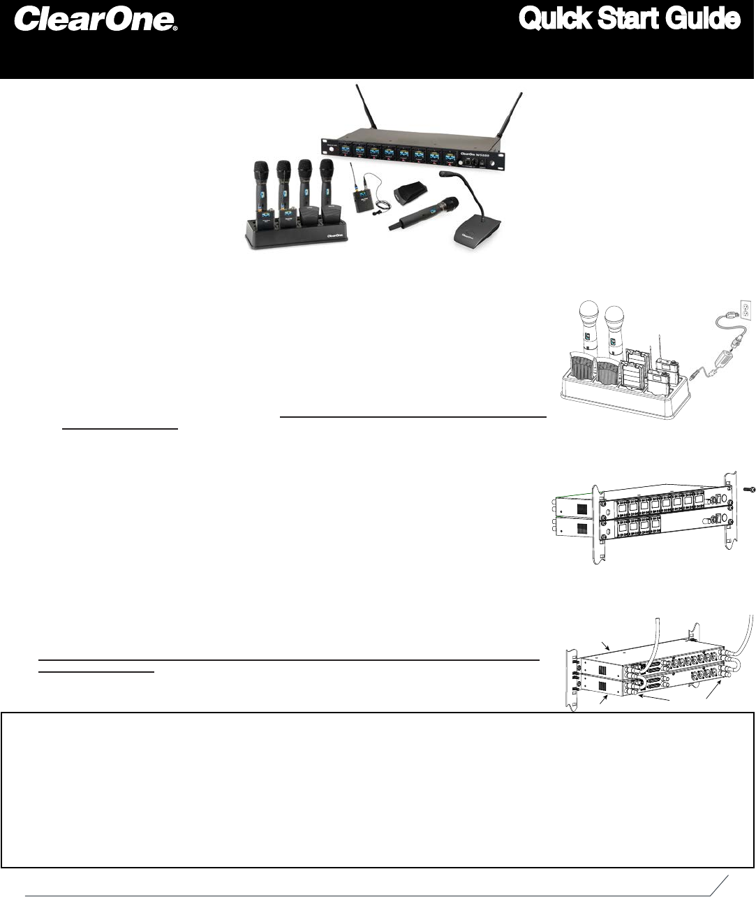
Open the Cartons: Conrm everything on the packing slip is enclosed.
Set up the Docking Staon:
1. ClearOne transmiers are shipped with rechargeable baeries. Plug
in the charging dock, put the baeries in the transmiers, then place the transmiers in the dock
while you set up the rest of the system.
Mount the Receivers in the Rack
2. and connect them to power. Conrm the displays light up.
Pre-engineered Antenna Design:
3. If you provided ClearOne with a oor plan, you will nd a
marked up version in the box (or, in your Email in-box) showing the antenna design along with the
antennas and pre-made cables. Place the antennas according to the drawings.
Your Own Design:
A. If you did not request an antenna design, place the antennas according to
the enclosed Antenna Applicaons Guide Improper antenna placement is the main cause of
poor RF performance.
Dipole Antennas:
B. Dipole antennas mounted to the rack equipment can easily be locked
away in a closet/rack cabinet. This results in poor RF performance because there is no line
of sight between the transmier and receiver antenna. Therefore, remote antennas are
preferred. See the Antenna Applicaon Guide for details.
Connect the Antennas:4. The receiver that connects to the antennas should be set as the
Antenna Master receiver. Master is the factory default. If your system daisy-chains antennas
together, the downstream receivers should be set as Slaves. Terminators are used on the
last system in the daisy-chain. Use ClearOne Remote’s Antenna Setup Wizard, which opens
automacally the rst me you connect. You can also nd the wizard under the SETTINGS tab
of the main page. If connecng ClearOne acve remote antennas, make sure the red LED lights
up. If not, check the receiver’s antenna phantom power seng using the ClearOne Remote
Control Soware.
Connect the analog outputs to the mixer:5. The system is shipped with Euro block connectors.
The default output level is set to +4 dBu. Note that factory default for the front panel headphone
jack is set for mixed line-level out. Use ClearOne Remote>Sengs>Headphone, to reset for
headphones.
CAUTION! Turn o phantom power from the mixer. Phantom power distorts the audio quality
of your microphones.
System Test:6. In most cases, the system is now ready to use. Conrm all channels pass audio
perfectly.
Modicaons (FCC 15.21)
Changes or modicaons to this equipment not expressly approved by ClearOne may void the user’s authority to operate this equipment.
This device complies with Industry Canada licence-exempt RSS standard(s). Operaon is subject to the following two condions: (1) this device may not cause interference, and (2) this device
must accept any interference, including interference that may cause undesired operaon of the device.
Applies to WS80-T:
Under Industry Canada regulaons, this radio transmier may only operate using an antenna of a type and maximum (or lesser) gain approved for the transmier by Industry Canada.
To reduce potenal radio interference to other users, the antenna type and its gain should be so chosen that the equivalent isotropically radiated power (e.i.r.p.) is not more than that necessary
for successful communicaon.
This radio transmier (WS80-T) has been approved by Industry Canada to operate with the antenna types listed below with the maximum permissible gain and required antenna impedance for
each antenna type indicated. Antenna types not included in this list, having a gain greater than the maximum gain indicated for that type, are strictly prohibited for use with this device.
Monopole antenna, 0dbi gain, 50 ohm impedance.
Le présent émeeur radio (DS80-T) a été approuvé par Industrie Canada pour fonconner avec les types d’antenne énumérés ci-dessous et ayant un gain admissible maximal et l’impédance
requise pour chaque type d’antenne. Les types d’antenne non inclus dans cee liste, ou dont le gain est supérieur au gain maximal indiqué, sont strictement interdits pour l’exploitaon de
l’émeeur.
For Full Control
Select the new parameter values and click OK to save
changes to the receiver.
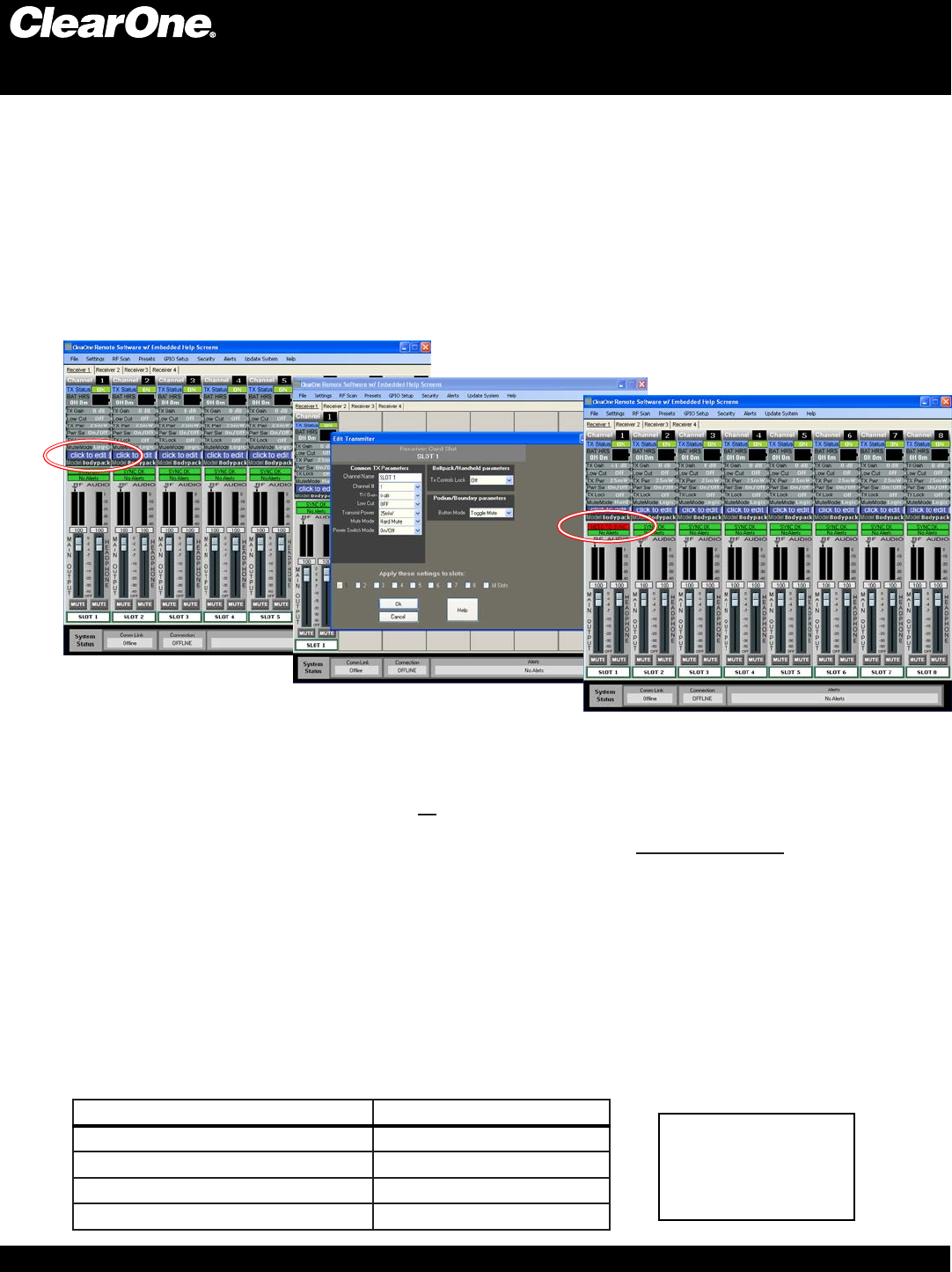
Eding Transmier Parameters:
The easiest and most intuive way to set the parameters of ClearOne transmiers and receivers is with ClearOne Remote soware.
Load ClearOne Remote from the disk provided onto a computer running Windows XP or Windows 7 (32 or 64-bit) and connect to the
receiver via USB or RS232. Then open ClearOne Remote and select ONLINE.
Open The Channel Edit Window:
1) The [Click to Edit] funcon opens the edit window of the channel you wish to edit.
2) Select the funcons you want to edit and enter the parameter. (The various funcons are described below.) Click [OK] to save the
changes and close the Channel Edit window.
3) You will noce that the [Needs to Sync] alert is lit. This indicates that one or more parameters are in queue in the receiver ready to
be downloaded and implemented with the next transmier Sync of the channel.
1)
2)
Digital Wireless Microphone Systems
Using the ClearOne remote soware:
Click to Edit the channel’s parameters
3)
The “Need To Sync” alert is lit. Sync the transmier to apply the selected parameters.
ClearOne Remote provides the following funcons:
File:1. Save a PDF image of the screen.
Sengs:2.
Phantom Power:A. Turn antenna phantom power on or o. Default = ON.
Redundancy: B. Set adjacent pairs of receivers to redundancy mode. Default = OFF.
Headphone Mode:C. Toggles the mixed output jack from headphone mode to a balanced line output. Default = Balanced
line output.
Ethernet Sengs: 3. If using Ethernet, assign the proper IP address to the ClearOne Receiver.
RF Scan - RF Plot: 4. Shows the RF strength of each antenna in a ClearOne system and shows if there is outside interference.
Presets: 5. Save or load preset system parameters conguraons. Default = As Ordered.
GPIO:6. Assign contact closure funcons and setup for RS232 control. Default = RS232 - Output mutes.
Security: 7. Password to prevent unauthorized changes: (Under construcon). Default = none.
Alerts: 8. Send alerts to authorized personal when prevenve maintenance is required of if there is a fault. Default = none.
Update System: 9. Checks to see if the system has the most current rmware and provides a wizard for updang the rmware.
Help:10.
Tutorials:A. Seng parameters, Antenna Applicaon Guide, etc.
About: B. Shows vital stascs for each component of the system
Transmier + Last 4 digits of serial Number Default Transmier Preamp Gain
BLT XXXX +10 dB
HH XXXX H18 = 0dB, H13 & H18 = +20dB
PDM XXXX +10dB
BDM XXXX +20dB
Default Transmier Preamp Gain Sengs:
BLT = Beltpack
HH = Handheld Mic
PDM = Podium Mic
BDM = Boundary Mic
Key:
1) Locate the IR (infrared) Sensor on the transmier
3) Hold transmier about 6 inches from the corresponding receiver module with the IR sensor aimed at the receiver module.
4) Simultaneously press the two buons on the boom of the corresponding receiver module to start sending the IR signal.
“SYNCING” shows on the receiver OLED when the IR signal starts. “SYNC OK” shows when the sync is successful. Repeat the
procedure if the receiver display shows “SYNC FAILED”. It is not necessary to press any buons on the transmier during the
procedure. Note: You may get a “Sync Failed” message if the receiver antennas are not in the same room as the receiver. In this
case verify that either the transmier display shows “Sync Good” OR the green LED on the transmier ashes. Also make sure to
dock each transmier aer syncing to avoid 2 transmiers being synced to the same receiver frequency.
IR
IR USB
ON / OFF
IR
IR
IR
ON/OFF
IR USB
How to sync transmiers with the receiver:
NOTE: The transmier and receiver are assigned a new, random AES 256-bit encrypon key every me they are synced.
Digital Wireless Microphone Systems
2) Power on the transmier.
NOTE: All transmiers placed in the charging dock will “RF MUTE”.
How to read the LED:
The OLED shows
the baery status
1. The gooseneck or
boundary mic is in use:
2. The gooseneck baery cassee
is in the docking staon:
4. Hand-held mic or belt-pack is
in the docking staon:
l RED = AUDIO MUTE
l GREEN = AUDIO PASSES
l BLINKING RED SLOW= BATTERY IS LOW
l BLINKING RED FAST = BATTERY IS BAD
l BLINKING GREEN = SYNC SUCCESSFUL
l RED = CHARGING
l OFF/OR GREEN = FINISHED CHARGING
l BLINKING RED = CHARGING ERROR
(RE-SEAT TRANSMITTER AND CHECK THE BATTERIES)
3. The boundary mic is in the
docking staon:
l RED change to AMBER = CHARGING
l GREEN = FINISHED CHARGING
l GREEN & RED BLINKING = CHARGING ERROR
(RE-SEAT TRANSMITTER AND CHECK THE BATTERIES)
IMPORTANT: Turn o all transmiers, except the one that is being synced, to avoid two transmiers being synced to
the same receiver frequency.
Digital Wireless Microphone Systems
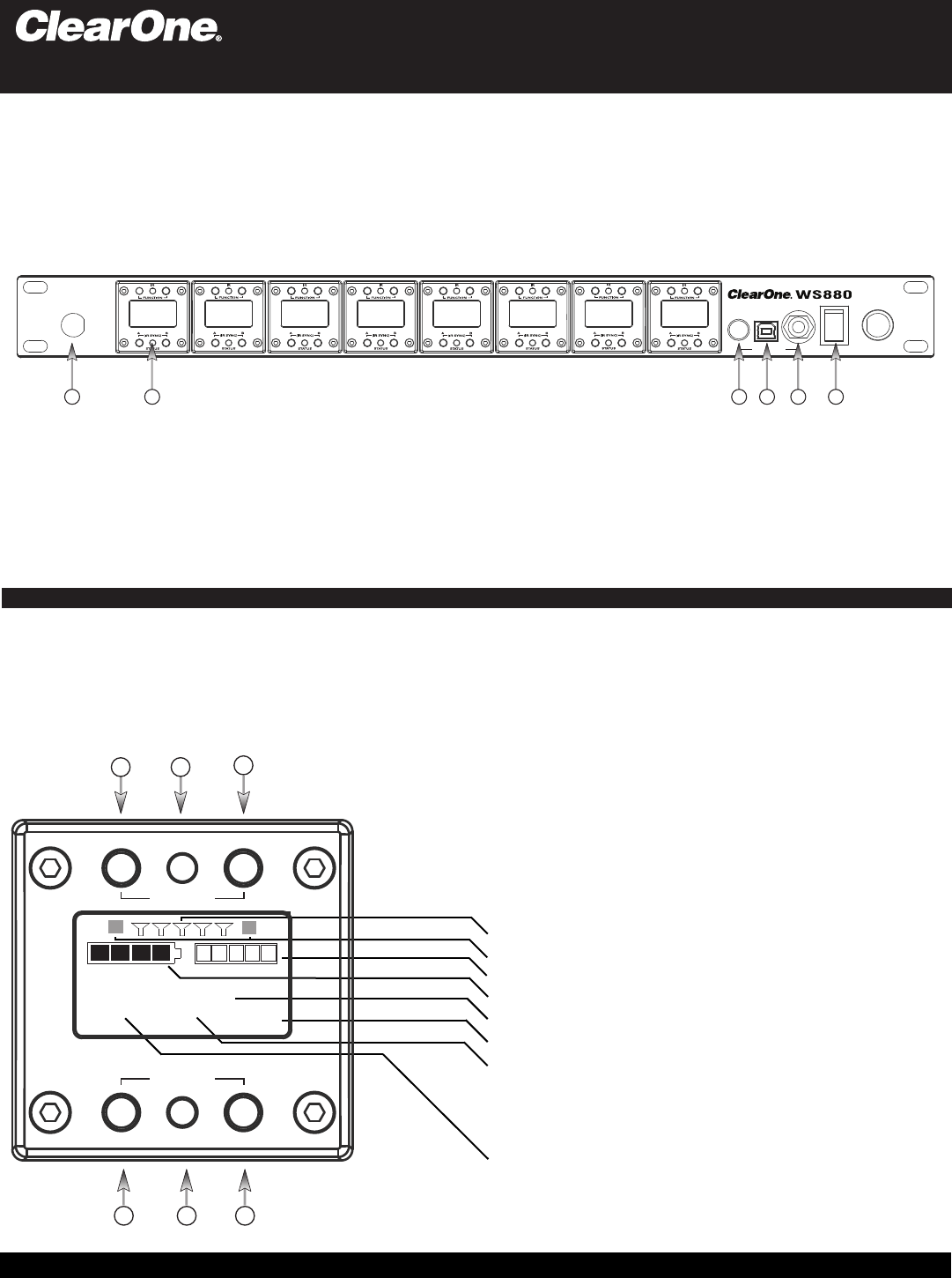
Receiver:
Made In USA
POWER
PHONES
USB
124 5 63
Antenna Front Mounng Hole: Use back-to-front TNC cables included.1.
Receiver Module. See details below2.
Mixed audio volume control.3.
USB Port. Connect to computer for 4. ClearOne Remote control. Run soware to monitor/edit system parameters, scan for
RF interference and download rmware upgrades.
Mixed audio output, 1/4” (5. See headphone mode - Pg. 2) phone jack for monitoring individual channels or mixed channels.
Power Switch.6.
ClearOne receiver main-frames hold either four or eight, independent, 24-bit digital audio receiver modules. There is a front-panel
mixed audio output for headphones or direct recording. Each module shares the main-frame’s two antennas for full-diversity. Up to
eight receiver main-frames can be daisy-chained together into an antenna network that shares two antennas. This eliminates the
need for external antenna distribuon amps. Main-frames can be connected to form an Ethernet network that monitor and control
the system via a computer. Main-frames also have USB and RS233 connecons for serial monitor and control. AES/EBU digital
audio output and word clock sync is oponal.
1. Select Next Funcon: Move the cursor to the next menu funcon on the display
(Under construcon)
2. IR Sync LED: Sends IR informaon to SYNC the receiver and transmier (SYNC pg3)
3. Select Previous Funcon: Move the cursor to the previous menu funcon
(Under construcon)
4. So Key Le: Select the choice displayed in the boom le of the display
4 & 6 pressed at the same me: Sends SYNC signal from receiver to transmier (SYNC pg3)
5. Status LED:
Green --> The channel is ON and un-muted
•
Red --> The channel is OFF•
Flashing Red --> Encrypon key mismatch, Re-sync receiver with transmier•
Amber --> The receiver is muted or GPIO is triggered•
Modules are designed for quick and easy
eld replacement for added redundancy.
123
4 5 6
RECEIVER MODULE:
FRONT PANNEL:
6. So Key Right: Select the choice displayed in the boom right of the display
BATTERY AUDIO
SLOT 3
CH 1 ON AES256
RF BARS
AUDIO LEVEL
BATTERY LEVEL
CHANNEL NAME
ENCRYPTION
STATUS:
ON = Green
OFF = Red
MUTE = Amber
KEY = Flashing Red (“KEY” = mismatched encrypon key)
MODULE:
FREQUENCY
12
ANTENNA DIVERISITY
(Colored text indicates status)
STATUS
SELECT
FUNCTION
(SYNC)
IR
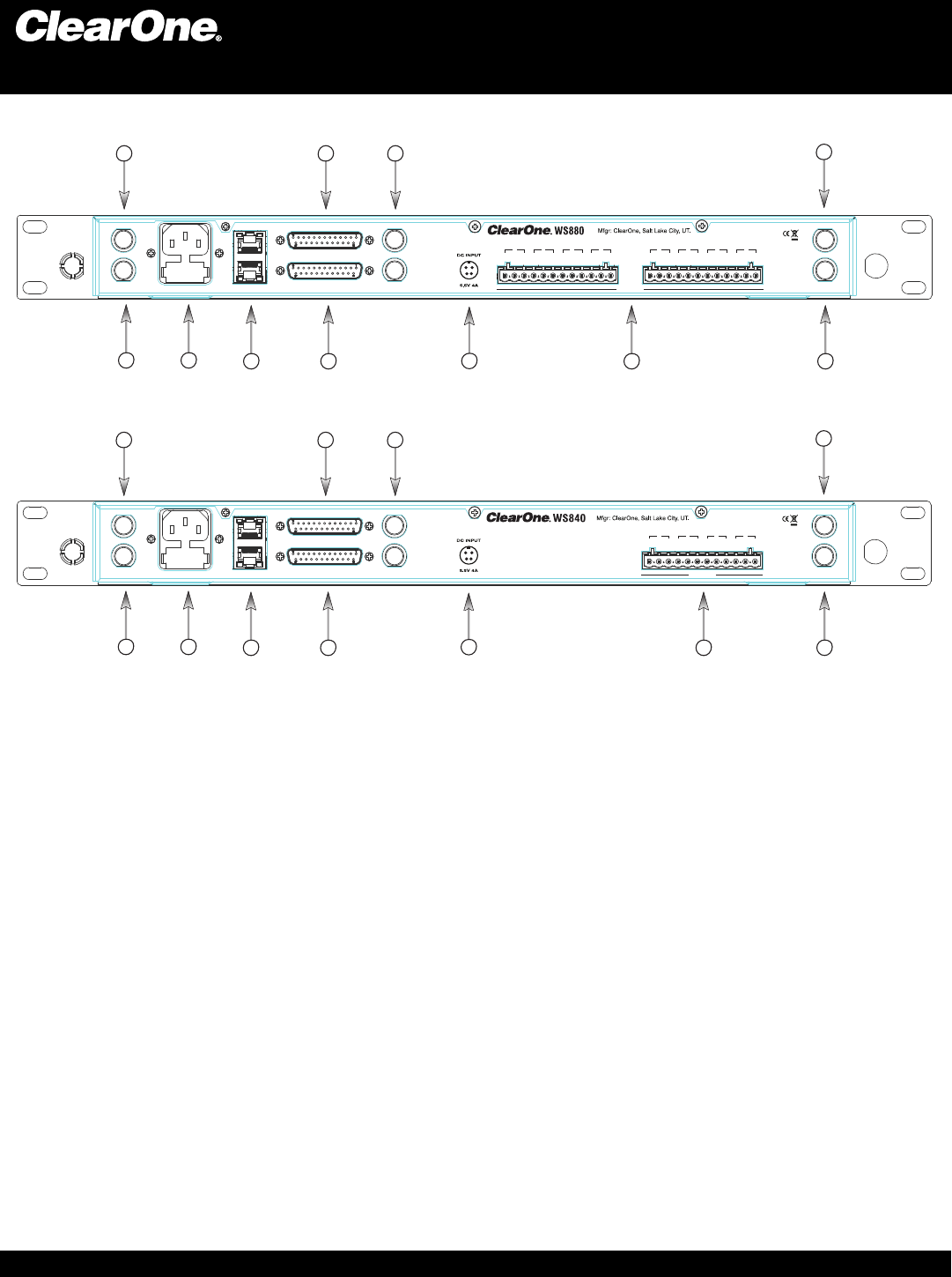
BACK PANEL WS880:
Antenna A Input:1. TNC connector for dipole antennas (included), front-to-back antenna cables (included), or antenna cable to
active extension antenna.
Antenna A Output:
2. Daisy-chain to the input of another receiver-frame to form an antenna network.
Power Cord Input:
3. (Cord with local plug configuration Included). 100-240 VAC, 50/60Hz, 15 W, 250V 320mA slow-blow fuse
(spare included)
Ethernet:
4. Connect to a computer or network. Multiple receiver-frames can be daisy-chained together to form a network. (Under
construction)
AES/EBU-3 Digital-Audio Output:5. Uses the standard Yamaha wiring convention(1). (NOTE: This feature is optional. The
connector jack is included on all receivers, but the feature must be specified at the time of purchase. It cannot be added at a later
date.)
BNC connectors:
6. for word clock digital-audio synchronizing.
GPIO/RS232:
7. This connector combines a General Purpose Input / Output (GPIO) and a RS232 on one DB25 connector. The
RS232 can be disabled to add up to 24 GPIO pins.
RS232: The pinout for the RS232 is the standard pinout. Pin 2 on the receiver is transmit, pin 3 is receive, and pin 7 is ground.
Most computers now use a DB9 connector for RS232. The standard off-the-shelf DB9 to DB25 cable will work. This cable swaps
pins 2 and 3 internally. If you computer has a DB25 connector for RS232, use a straight DB25 to DB25 cable. Do not use a null
modem cable.
GPIO: GPIO acts like a contact closure. Use ClearOne Remote to assign an event that toggles the GPIO pin. The factory
default toggles pins X through X to correspond to muting a receiver module. ClearOne Remote has a feature that lets you assign
how the system responds to a transmitter mute (see ClearOne Remote)
A. Mute the channel’s receiver audio. (Factory default)
B. Toggle the GPIO but do not mute the receiver audio. Use this with automated mixers or echo cancelling DSPs.
C. Mute the channels receiver audio and toggle the GIPO pin.
Audio Output Jacks:
8. Configured for four or eight-module receiver frames and for XLR or Euro-block terminal connectors.
Antenna B Input:
9. TNC connector for dipole antennas (included), front-to-back antenna cables (included), or antenna cable to
active extension antenna (see section on antennas, antenna placement and antenna cables).
Antenna B Output:
10. Daisy-chain to the input of another receiver-frame to form an antenna network.
DC Input:
11. Optional external DC power source eliminates the need for AC input or, can be used as a redundant, back-up power
source.
8
Digital Wireless Microphone Systems
Receiver:
AES
3
50-60
Hz
100-240
VAC ANTENNA A
ETHERNET WORD CLOCK
ANTENNA B RS
232
-GPIO
4
G
-+
3
G
-+
2
G
-+
1
G
-+
Made In USA
OUT
IN
IN
OUT
OUT
IN
MIC OUTPUTS
BACK PANEL WS840:
MIC OUTPUTS
AES
3
50-60
Hz
100-240
VAC ANTENNA A
ETHERNET WORD CLOCK
ANTENNA B RS
232
-GPIO
4
G
-+
3
G
-+
2
G
-+
1
G
-+
8
G
-+
7
G
-+
6
G
-+
5
G
-+
Made In USA
OUT
IN
IN
OUT
OUT
IN
2347
1569
8
2347
1569
10
10
11
11
Digital Wireless Microphone Systems
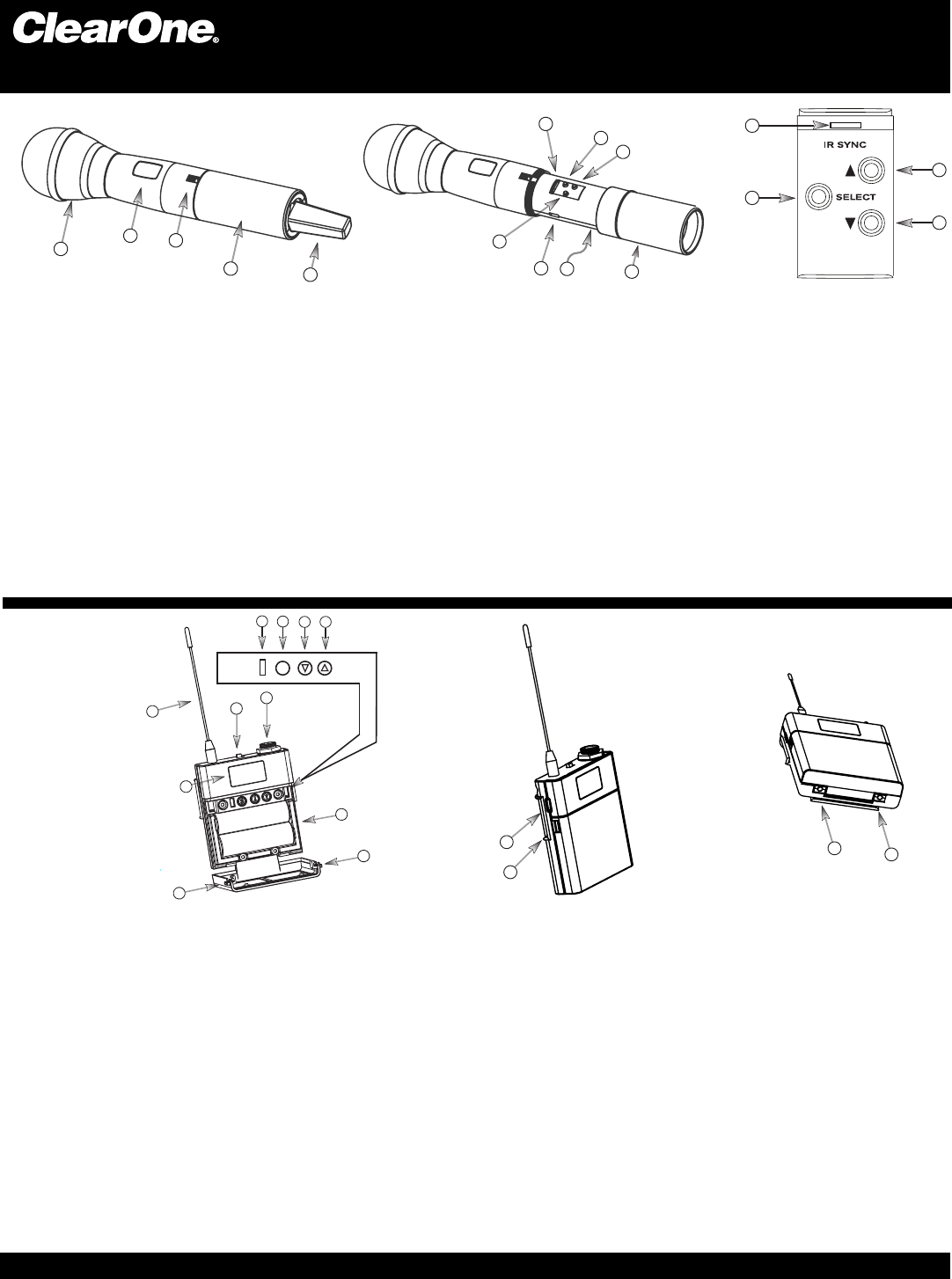
Transmiers:
1. Heads: Four (4) microphone elements are available, both condenser and dynamic, depending on the applicaon of the microphone
user (including Audix OM3 and OM5 dynamic heads). In general, condenser heads are more “transparent” and do not require the
microphone to be held as close to the mouth. On the other hand, dynamic heads are oen preferred for live performance because
they tend to accent the bass tones and they do not distort with very loud singing.
2. Display: OLED display is used to program and display the current status of the transmier funcons.
3. Switch: User programmable to toggle on/o, on/mute/ or on/on.
4. Baery and Control Cover: Unscrew counter-clockwise and gently slide open.
5. Antenna Cover: Do not hold the antenna cover. Your hand will shield the RF signal and cause poor audio performance.
6. IR Sensor Port: The IR sensor is used to transfer channel sengs and a random encrypon key from the receiver to the transmier.
7. Select buon: Press this buon to select a funcon. The rst press acvates the rst edit able funcon in the tree. Press again to move
to the next edit able funcon.
8. Parameter Up: Press this buon to increase the value of the selected funcon.
9. Parameter Down: Press this buon to decrease the value for the selected funcon.
10. USB Port: Plug a micro USB cable into the USB port to charge the baeries or upgrade the rmware.
11. Baeries: (not shown) AA NiMH, 2200 to 2500-mAHr recommended.
12. Baery Door: Open posion.
7
10
6
9
12
8
11
2
3
1
4
5
7
6
8
9
567
s
8
23
1
4
9
10
12
11
13
10
13
1. Antenna: Length and style varies with the transmiers model number. Antennas are eld replaceable to improve reliability and
redundancy.
2. Programmable Switch: Toggle on/o, on/mute/ or on/on.
3. Microphone Connector: TA4 mini XLR style: ClearOne® oers a full range of lavaliere and headset microphones for opmal performance
of your ClearOne® transmier. Works with both snap in and screw-in microphones.
4. Display: OLED display is used to program and display the current status of the transmier funcons.
5. IR Sensor Port: The IR sensor is used to transfer channel sengs and a random encrypon key from the receiver to the transmier.
6. Select: Press this buon to select a funcon. The rst press acvates the rst edit able funcon in the tree. Press again to move to
the next edit able funcon.
7. Parameter Down: Press this buon to decrease the value for the selected funcon.
8. Parameter Up: Press this buon to increase the value of the selected funcon.
9. Baeries: AA NiMH, 2200 to 2500-mAHr recommended.
10. Baery Door Locks: To open, press both at the same me and li the door open. To close, snap the door closed.
11. USB Port: Plug a micro USB cable into the USB port to charge the baeries or upgrade the rmware.
12. Belt-Clip: Spring-loaded clip for aaching the transmier to a belt or similar object. Spring pressure presses the clip into two holes in
the transmier body. Pull them out to remove or reverse the clip. Exercise cauon to prevent injury or scratching the case.
13. Contacts: Charging contact points for the docking staon.
HAND-HELD:
BELT PACK:
Digital Wireless Microphone Systems
Transmiers:
OFF/ON
IR USB
6
5
4
3
1
3
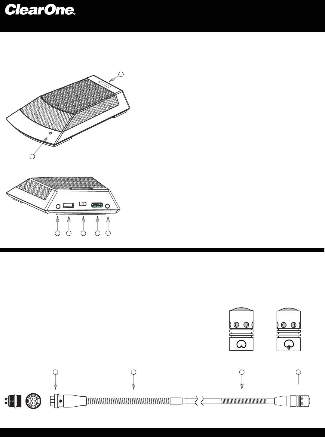
The ClearOne Conference Table-top Mic combines the professional audio specs and security of a wired mic with
wireless convenience. Available in omni or cardioid polar pick-up paerns with 265-bit FIPS 197 encrypon.
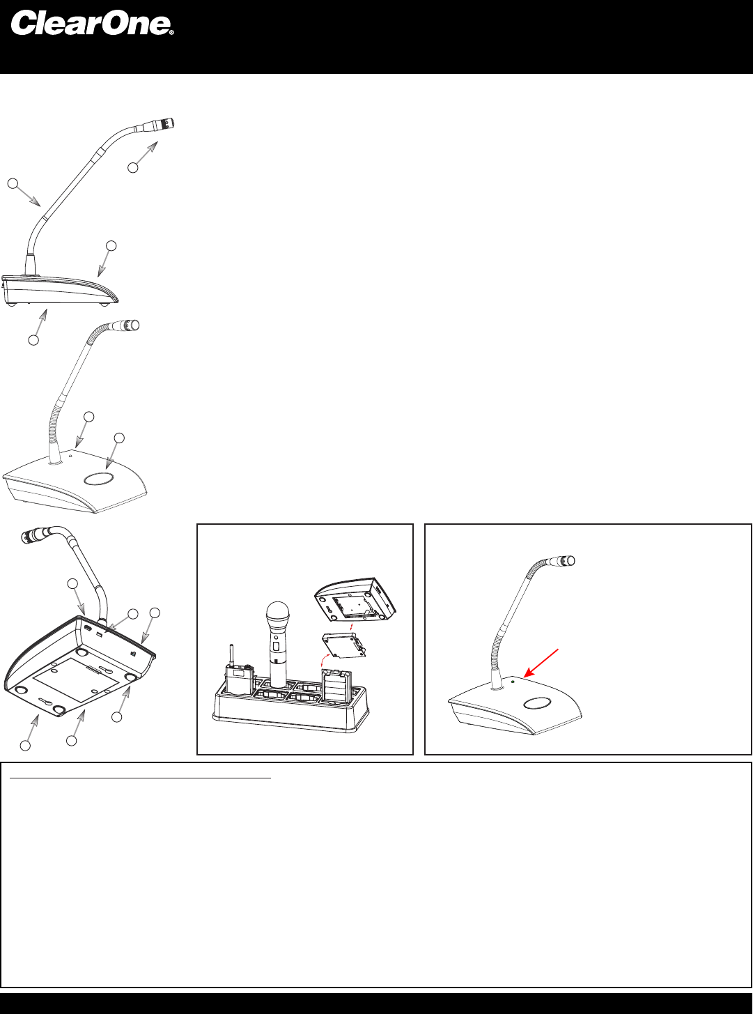
ClearOne Gooseneck Podium Mic Stems are available in
12” and 18” lengths that are interchangeable and feature
interchangeable capsules available in cardioid and super
cardioid polar paerns.
1. Interchangeable microphone capsule.
2. Flexible stem secon.
3. A 4-pin XLR connector allows the exchange of dierent
length microphone stems (12 and 18 inch lengths).
221
3
CONFERENCE TABLE-TOP:
PODIUM GOOSENECK STEM :
Capsules are interchangeable and are available in cardioid and
super cardioid polar paerns.
GOOSENECK MIC CAPSULE:
CARDIOID
SUPER
CARDIOID
21. Power LED: When the Table Mic is on, the LED signals:
l Red ........................ Audio Mute
l Green..................... Audio Passes
l Blinking Green....... Sync is Successful
l Blinking Red Slow.. Battery is Low
l Blinking Red Fast... Battery is Bad
2. Programmable switch: Talk, Mute, On/Off
3. Contacts: Contact points for the charging station.
4. I/R Sensor: Inputs programming instructions and encryption key
from the receiver.
5. Power Switch: On / Off.
6. USB Port: Doubles as the power supply / recharger connection
and computer programming port. The transmitter operates
normally under USB power, with dead or no batteries for permanent
installations.
Digital Wireless Microphone Systems
Transmiers:
PN: ClearOne-Quick-Start-Guide-130617.indd
3
2
1
4
87
9
11 10
12
(Figure 1) (Figure 2)
Recharge the batteries by inserting the
cassette into the ClearOne Charging Dock.
PODIUM GOOSENECK: The ClearOne Podium microphone combines the professional audio specs and security of a wired
mic with wireless convenience. For use with baery power or permanently install the microphone
using USB power.
ClearOne1. Capsules: Select cardioid or super-cardioid sensivity polar paerns.
Goosenecks:2. Two exible secons to extend over a laptop or briefcase. Available in 12, 18
inch lengths.
Radio-transparent ABS Top:3. Stylish design that hides and protects the antenna.
Cast Metal Boom:4. Zinc base boom adds stability and absorbs desk noise.
Power LED:5. (see g. 2 below)
Buon Programming Opons: 6.
ppress to talk
ppress to mute
ptoggle on or o
Power Switch Programming Opons: 7.
pOn / O
pOn / Mute
pOn / On.
USB Port:8. Doubles as the USB recharger connecon and computer programming port. The
transmier operates normally under USB power, with dead or no baeries for permanent
installaons. When charging using the USB Port, The LED signals: RED = Charging / OFF =
nished charging.
I/R Sensor:9. Inputs programming instrucons and encrypon key from the receiver.
Baery Cassee:10. Push tab to remove the baery cassee. Recharge the baeries by
inserng the cassee into the ClearOne Charging Dock. (See gure 1) The baery cassee
holds four, o-the-shelf, AA, NiMH baeries for up to 9.5 hours connuous usage per charge.
Keyholes: 11. For permanent mounng
Rubber Feet:12. Absorb desk noise and provide a stable, non-skid base.
5
6
RF Exposure Informaon for WS800 Digital Wireless Transmiers
l For the WS800 Handheld transmier:
When transming, hold the radio in a vercal posion with its microphone 2 inches (5 cm) away from your mouth and keep the antenna at least 2 inches (5 cm) away from your
head and body
l For the WS800 BodyPack transmier:
To maintain compliance with the Body Worn conguraon use only supplied accessories. Other body-worn accessories or conguraons may NOT comply with the FCC RF
exposure requirements and should be not be used.
l For the WS800 Podium transmier:
Keep the podium base at least 20 cm from your body.
l For the WS800 Conference Table-top transmier:
The antenna(s) used for this transmier must be installed to provide a separaon distance of at least 20 cm from all persons and must not be collocated or operang
in conjuncon with any other antenna or transmier, except in accordance with FCC mul-transmier product procedures. End-users and installers must be provided with antenna
installaon and transmier operang condions for sasfying RF exposure compliance.
l The informaon listed above provides the user with the informaon needed to make him or her aware of RF exposure, and what to do to assure that this radio operates with the
FCC RF exposure limits of this radio.
l This wireless microphone also complies with the following guidelines and standards regarding RF energy and electromagnec energy levels as well as evaluaon of those levels for
human exposure:
FCC OET Bullen 65 Edion 97-01 Supplement C, Evaluang Compliance with FCC Guidelines for Human Exposure to Radio Frequency Electromagnec Fields.
American Naonal Standards Instute (C95.1-1992), IEEE Standard for Safety Levels with Respect to Human Exposure to Radio Frequency Electromagnec Fields, 3 kHz to 300 GHz.
American Naonal Standards Instute (C95.3-1992), IEEE Recommended Pracce for the Measurement of Potenally Hazardous Electromagnec Fields — RF and Microwave.
Cered under FCC part 15.247 / Cered by IC in Canada under RSS-210
FCC: RBODS80P, RBODS80T, RBODS80H, RBODS80C / IC: 8240A-DS80P, 8240A-DS80T, 8240A-DS80H, 8240A-DS80C
When the Gooseneck Mic is in use, the LED signals:
RED = AUDIO MUTE
GREEN = AUDIO PASSES
BLINKING RED SLOW= BATTERY IS LOW
BLINKING RED FAST = BATTERY IS BAD
BLINKING GREEN = SYNC SUCCESSFUL