Cleveland Medical Devices 0007 Biomedical Telemetry Transmitter User Manual 392 0000rev1
Cleveland Medical Devices Inc. Biomedical Telemetry Transmitter 392 0000rev1
UserManual.wiki
>
Cleveland Medical Devices
>
0007 User Manual
Exhibit F
Navigation menu
Upload a User Manual
Namespaces
Wiki Guide
HTML
PDF
Info
Views
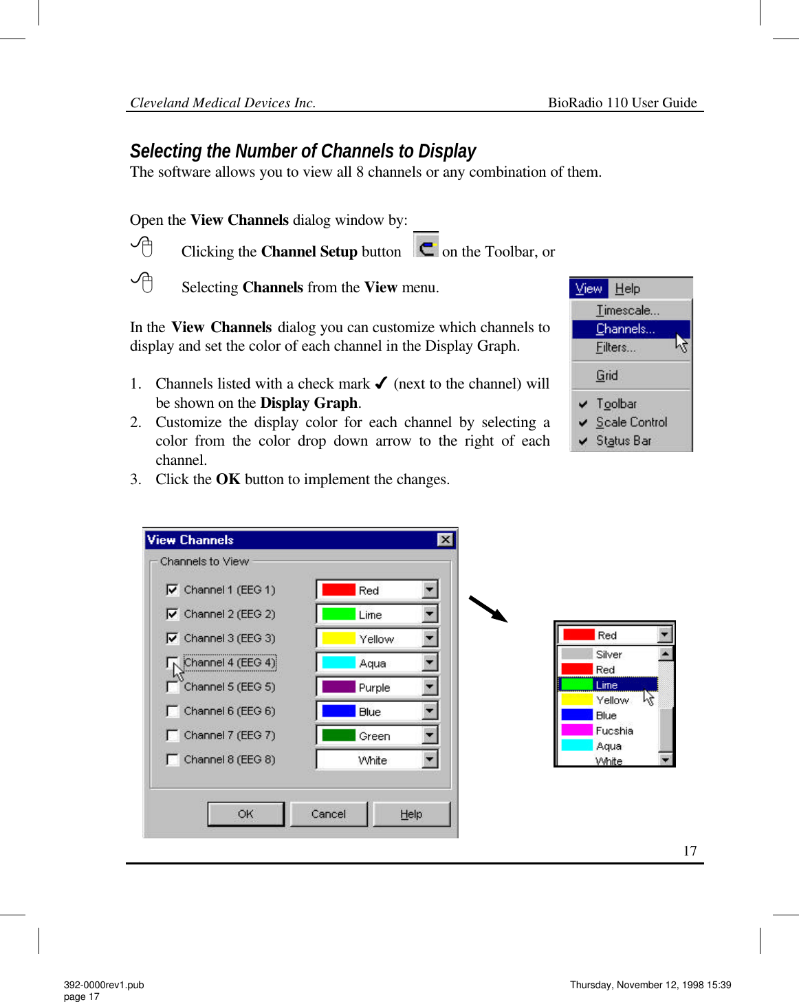
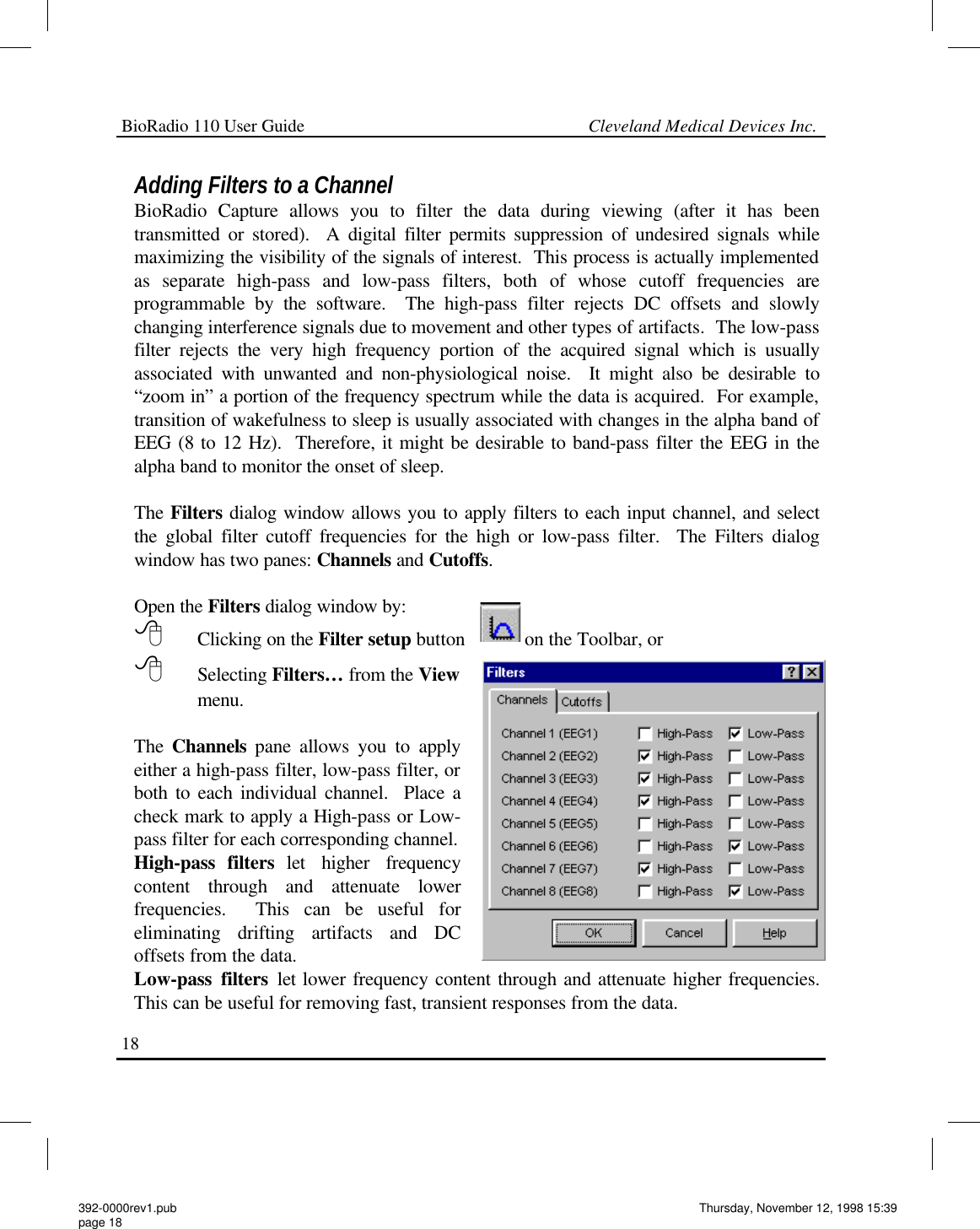
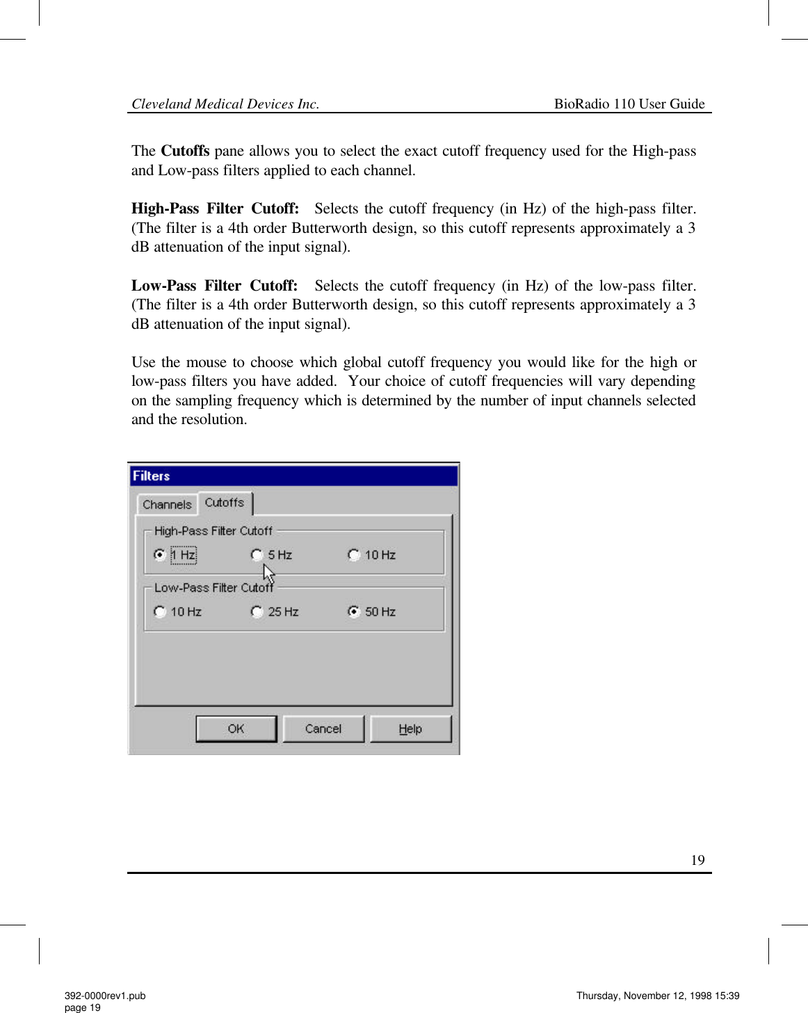
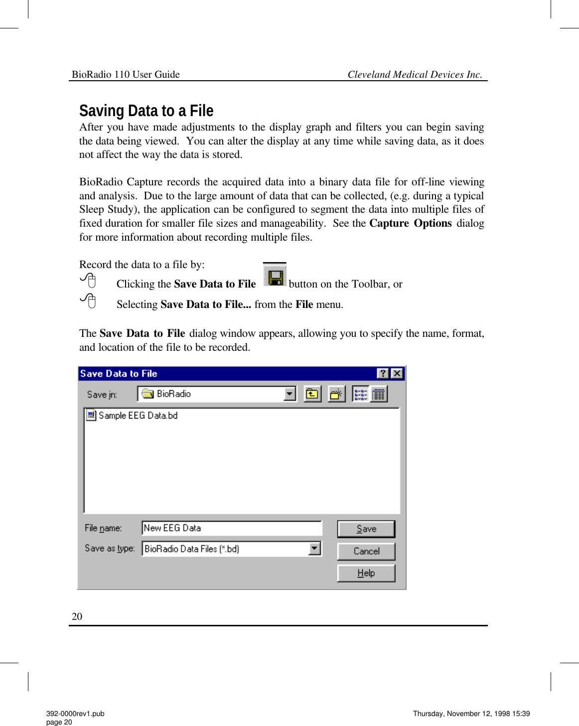
User Manual
Discussion / Help
Navigation