Climax Technology Co 1818 IP Camera User Manual VST 1818WI IP Camera 20150730
Climax Technology Co Ltd IP Camera VST 1818WI IP Camera 20150730
UserManual.wiki
>
Climax Technology Co
>
1818 User Manual
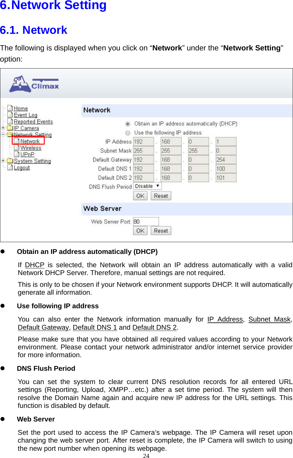
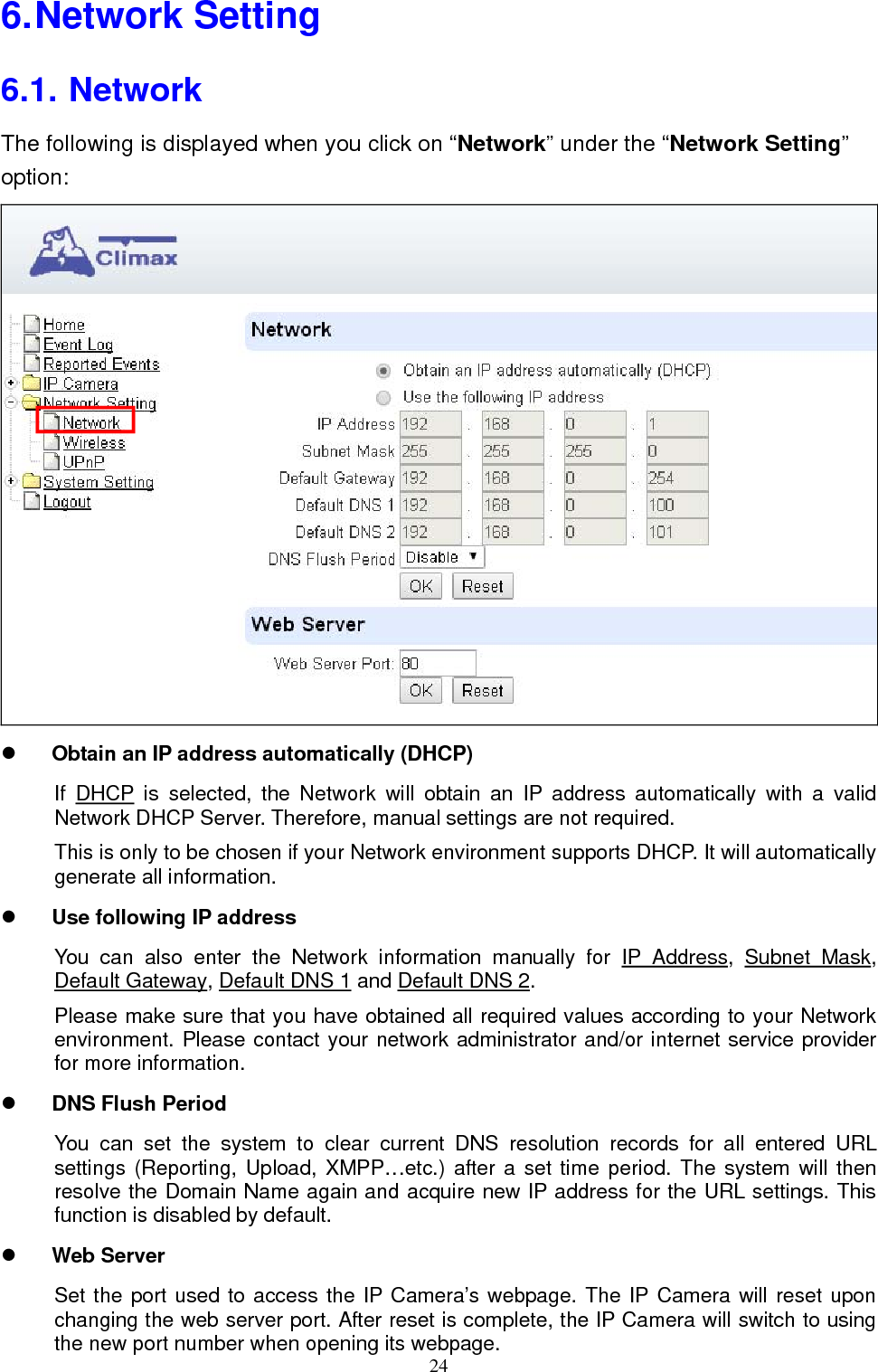
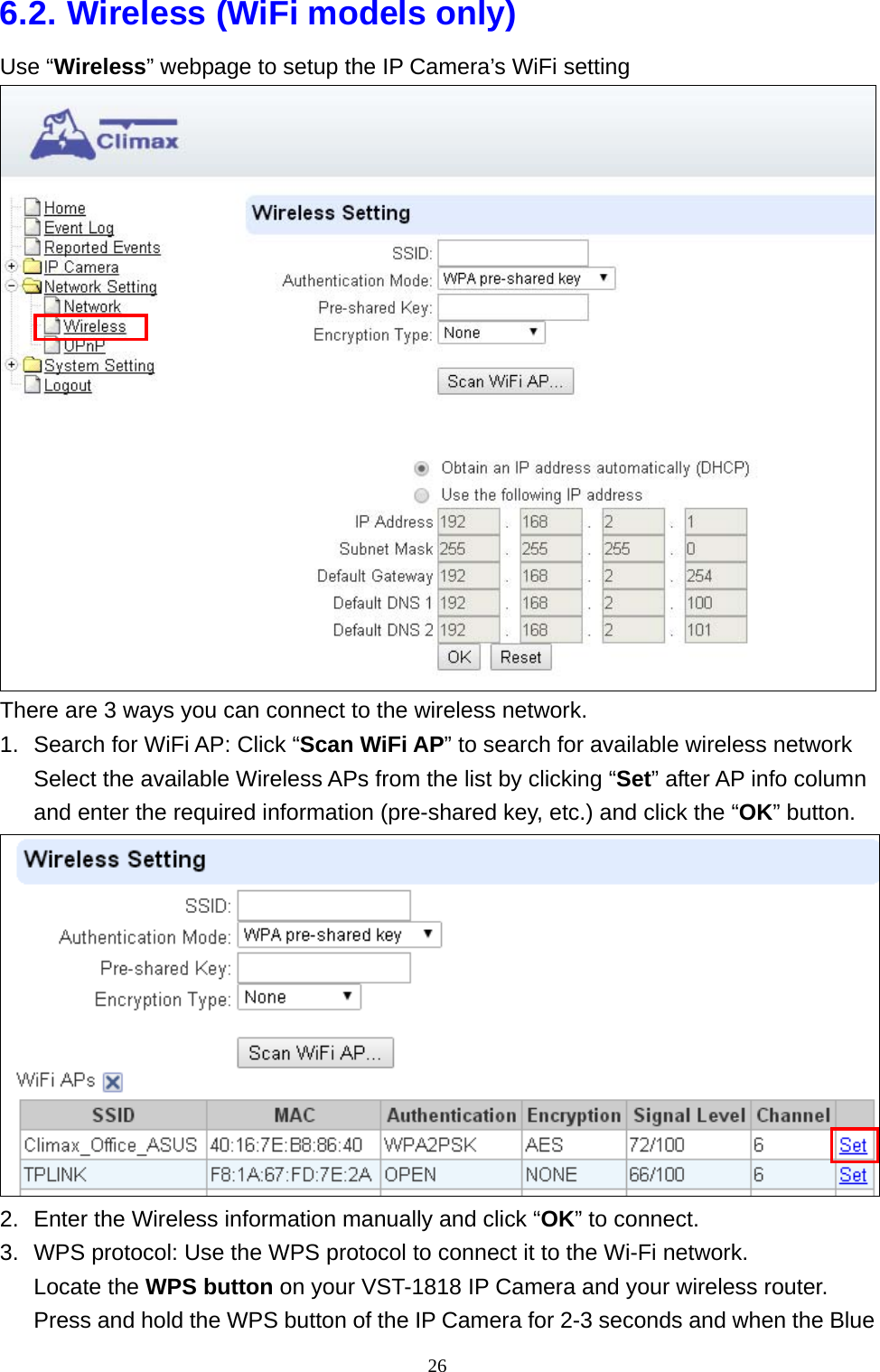
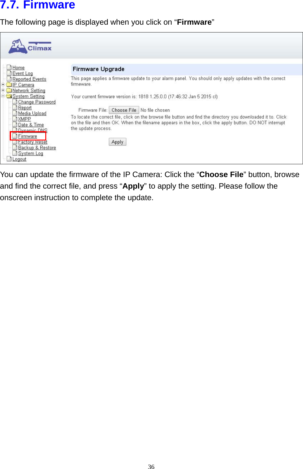
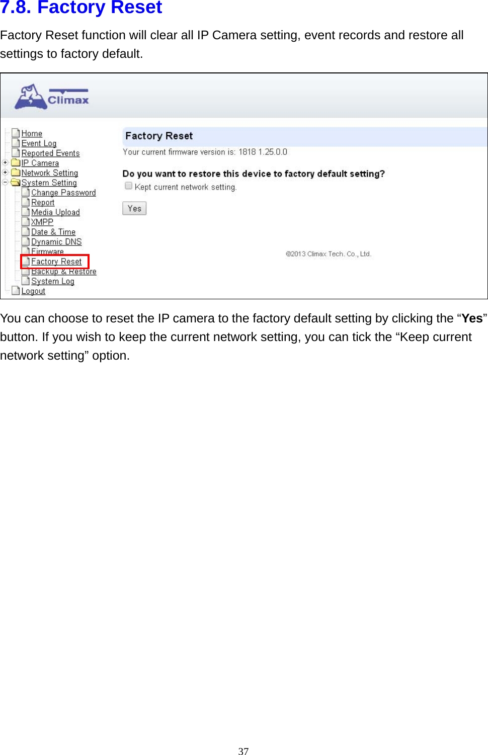
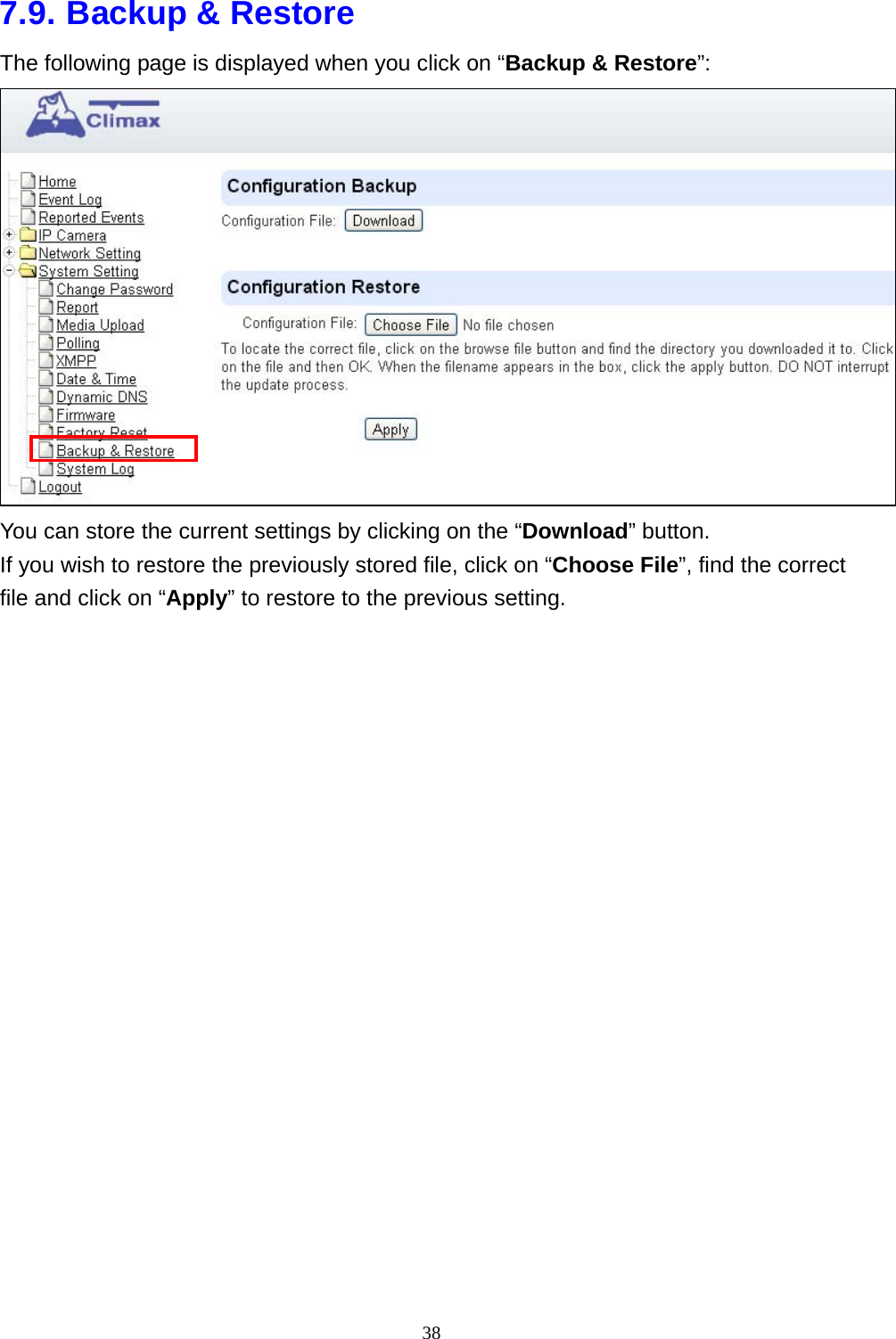
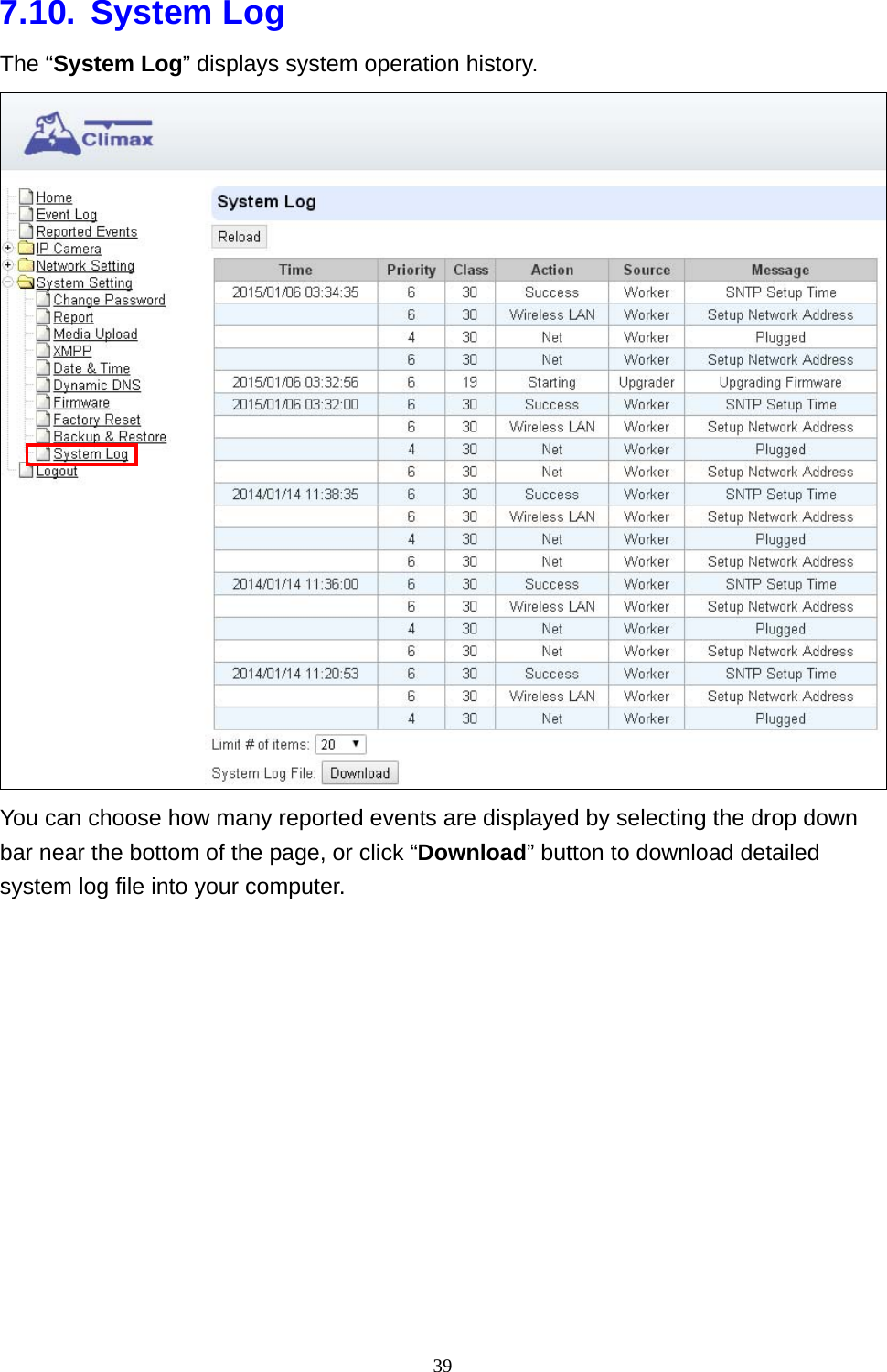
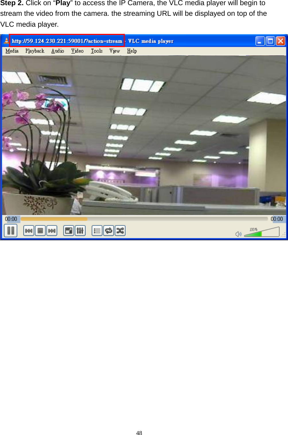
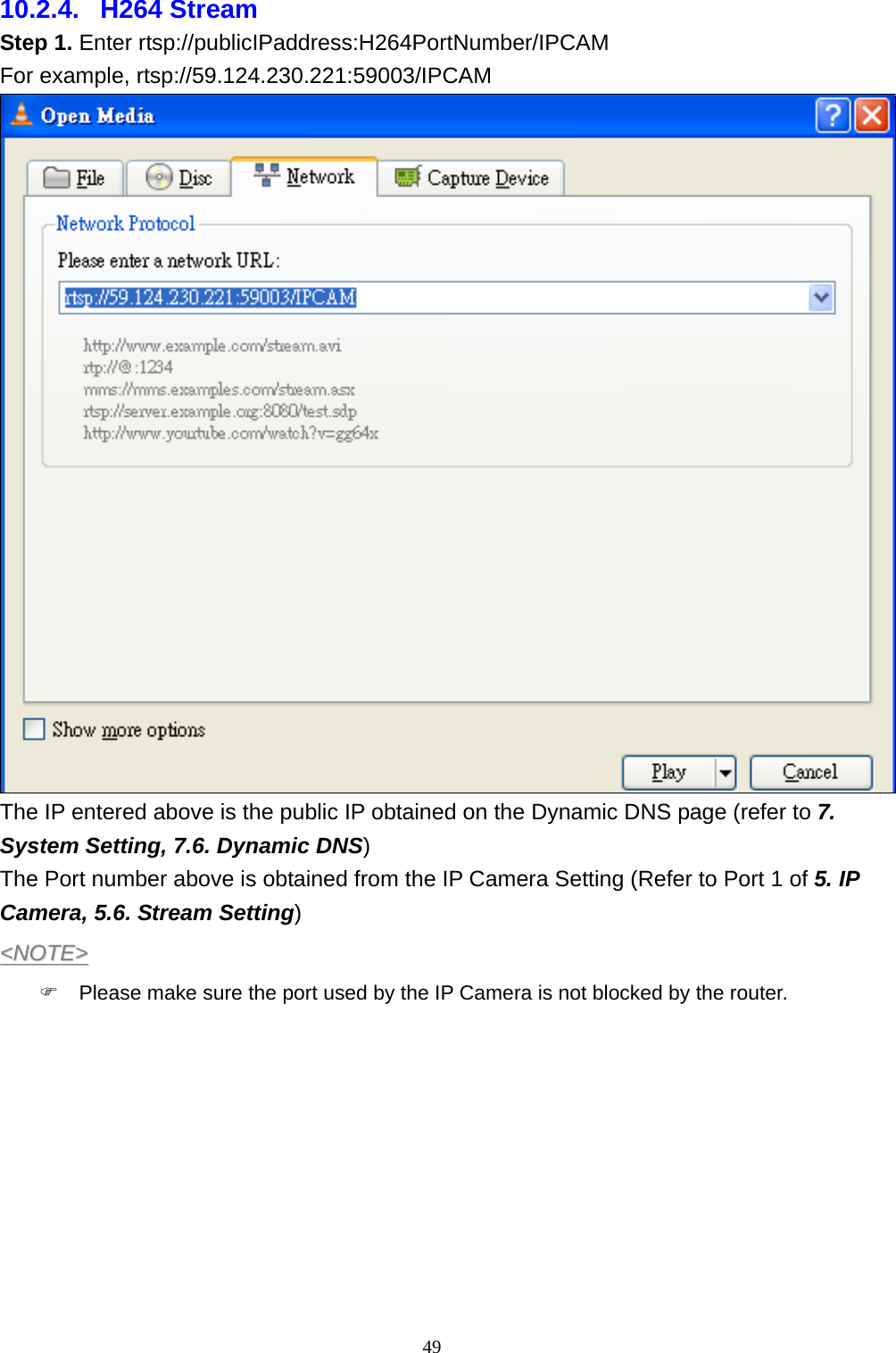
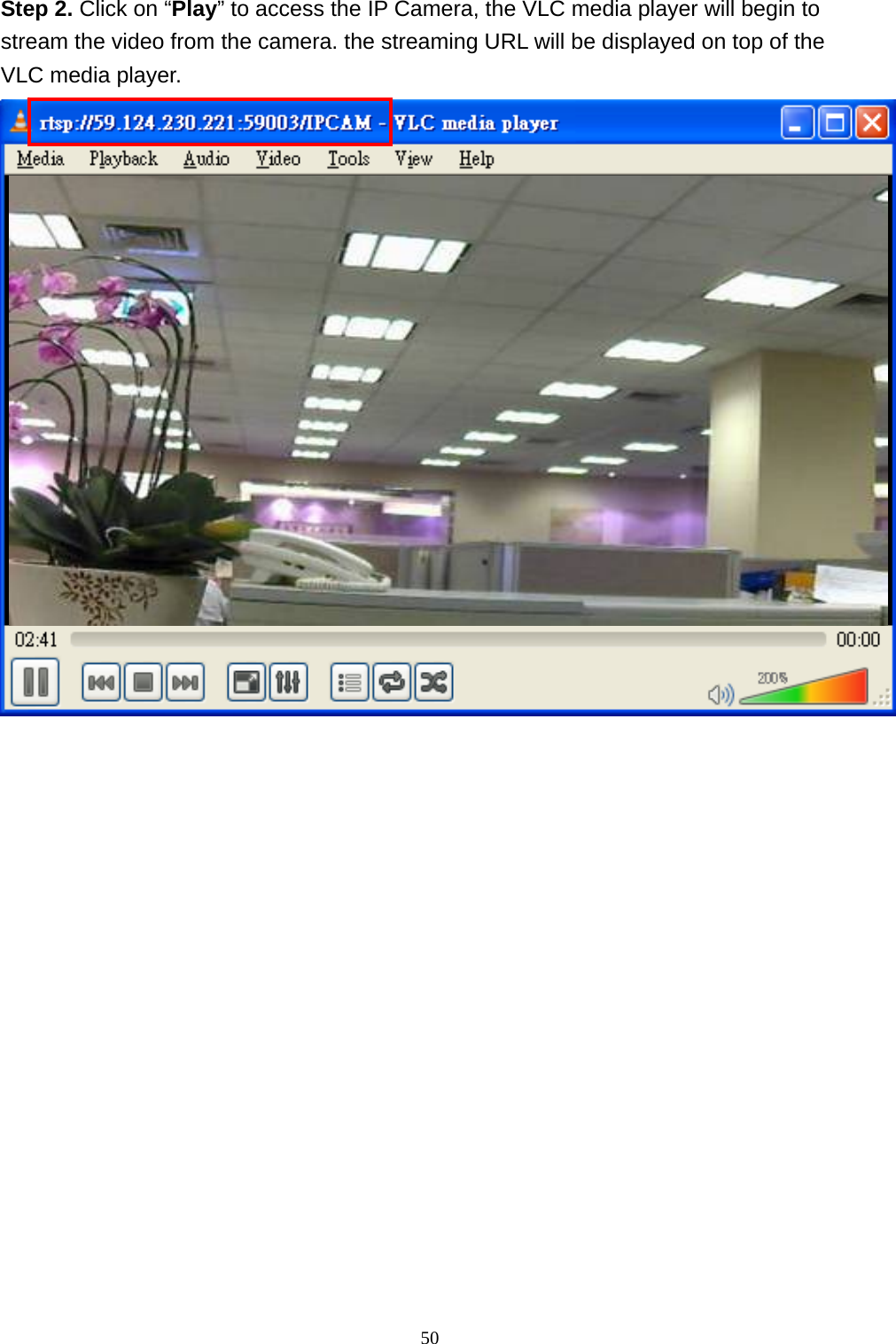
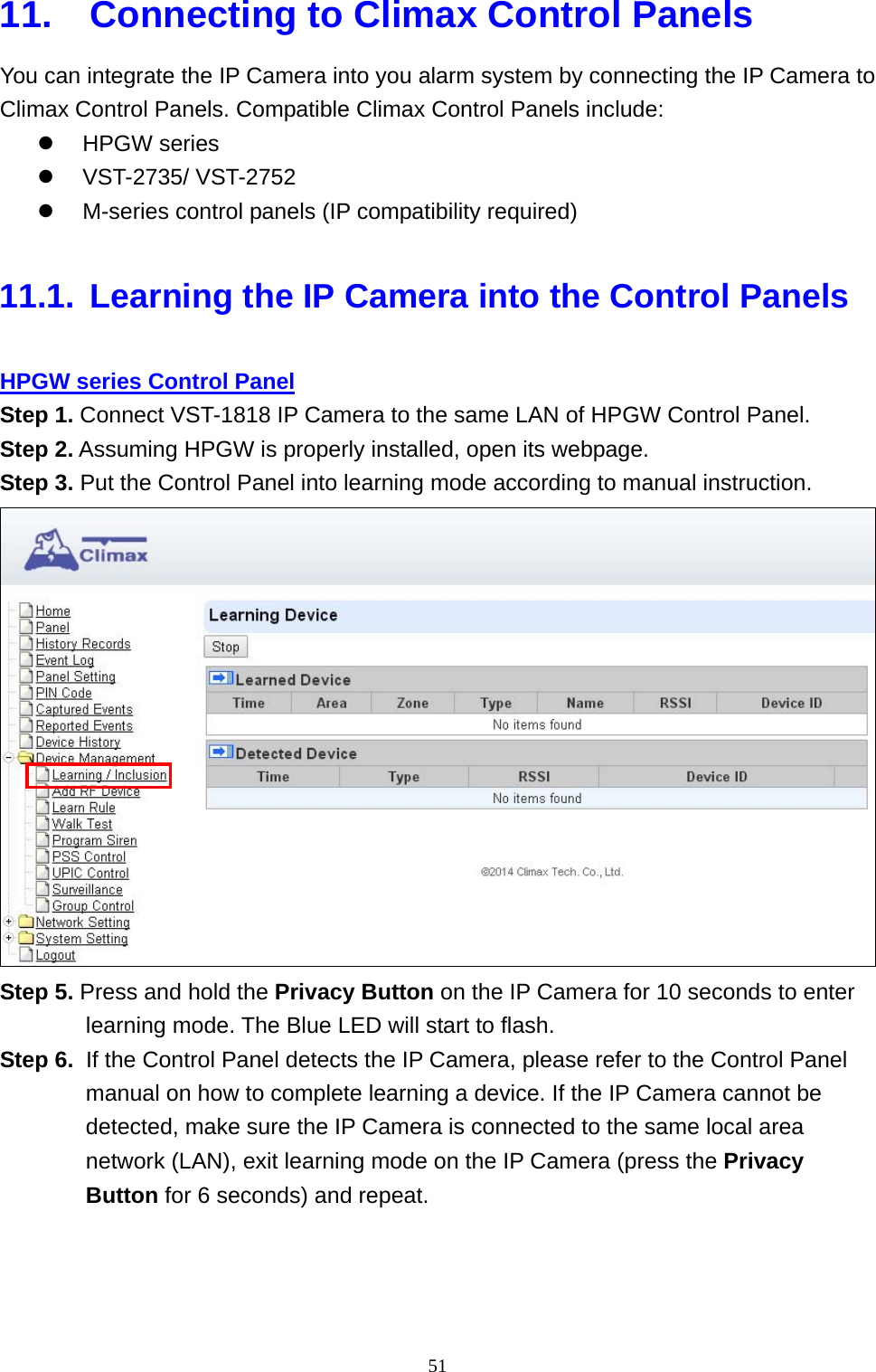
Users Manual
Navigation menu
Upload a User Manual
Namespaces
Wiki Guide
HTML
PDF
Info
Views
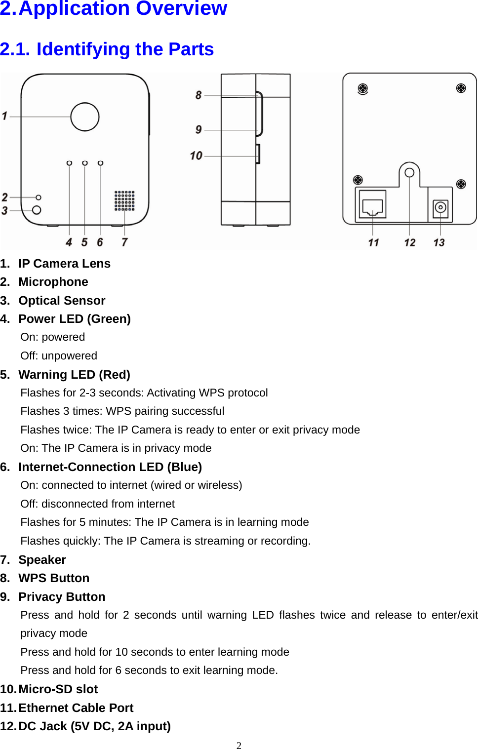
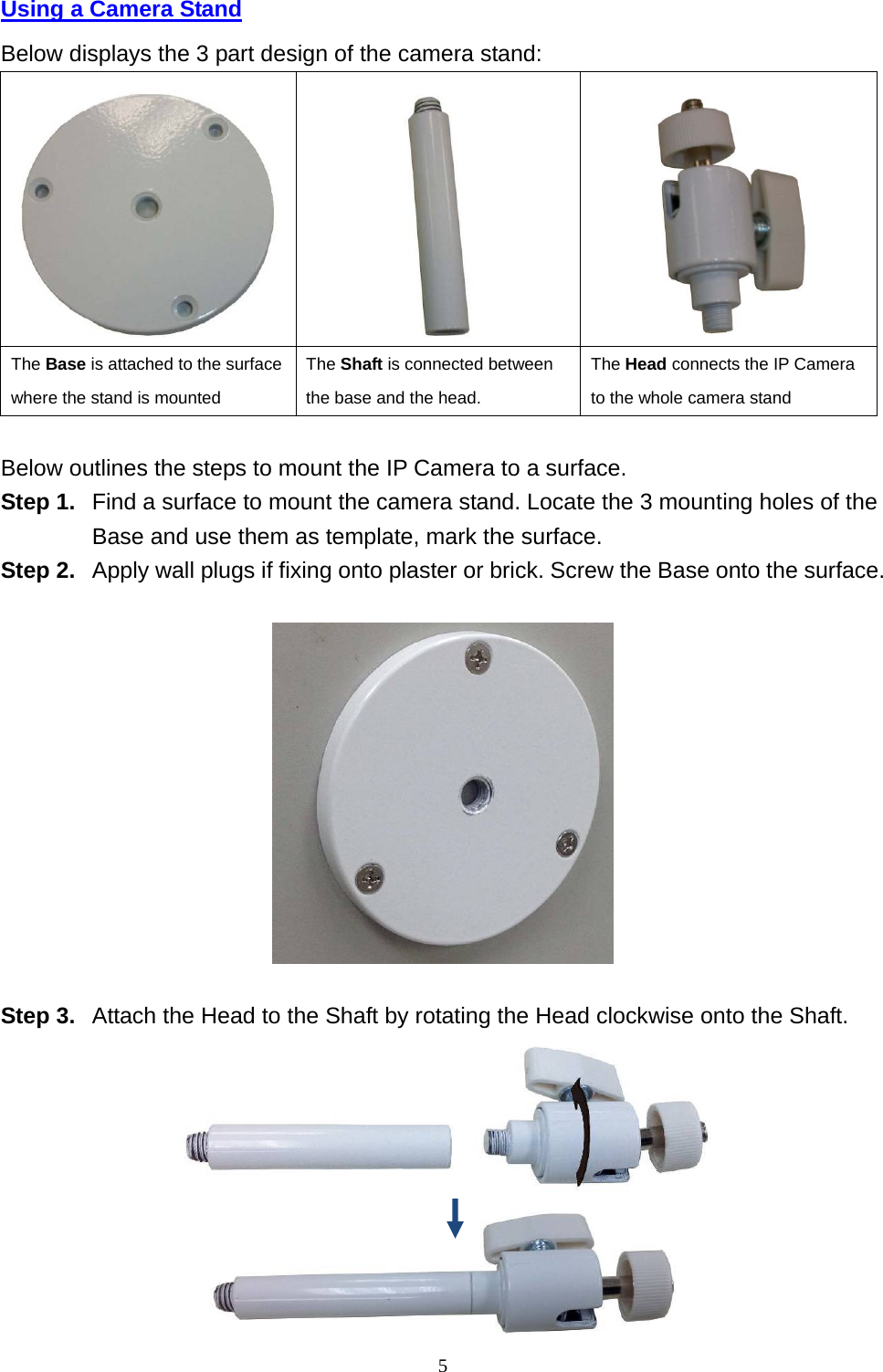
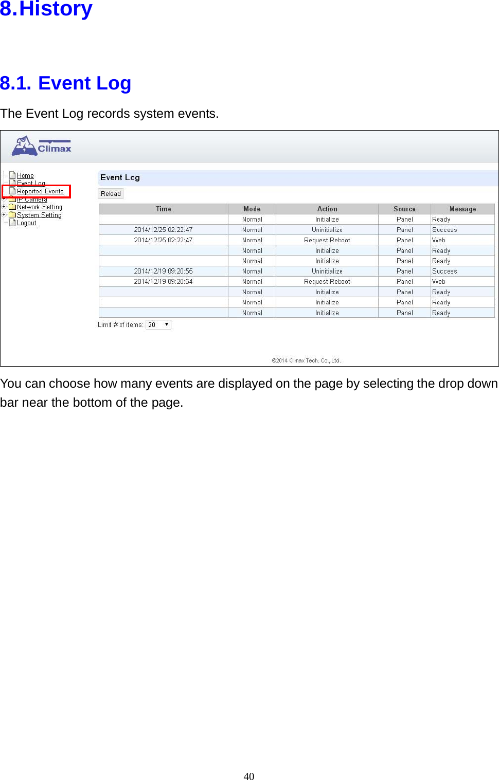
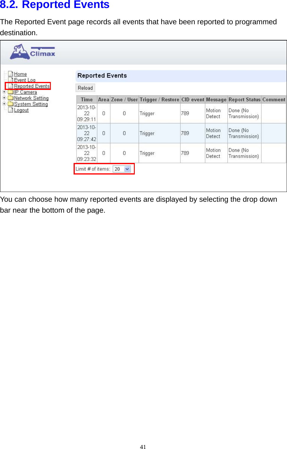
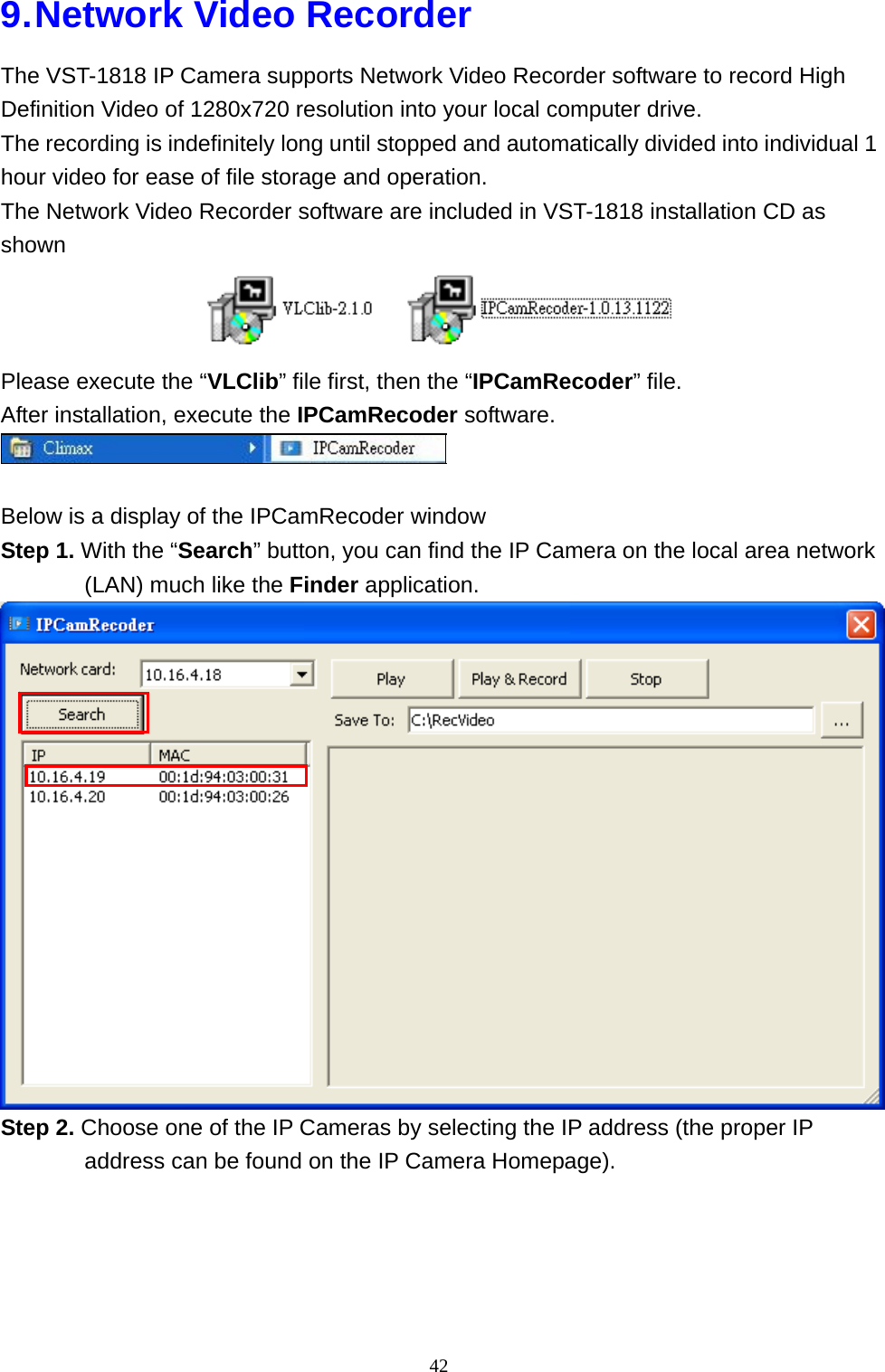
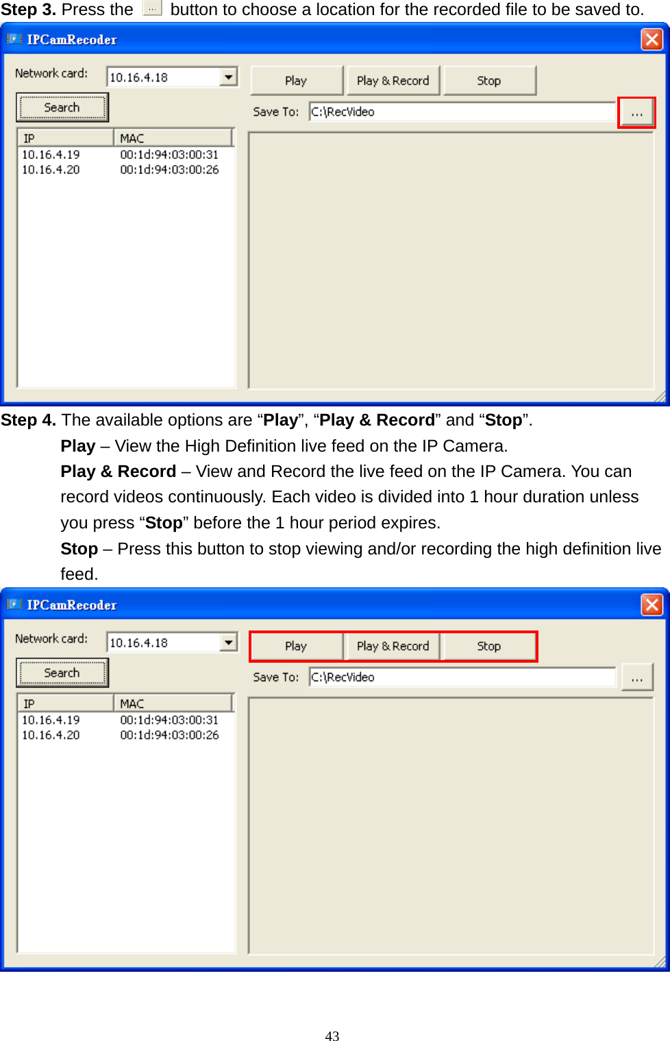
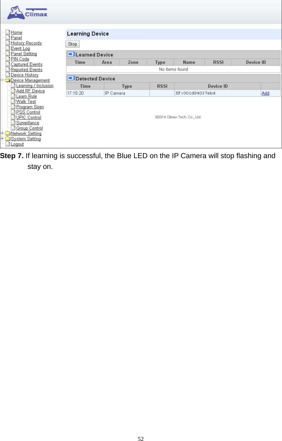
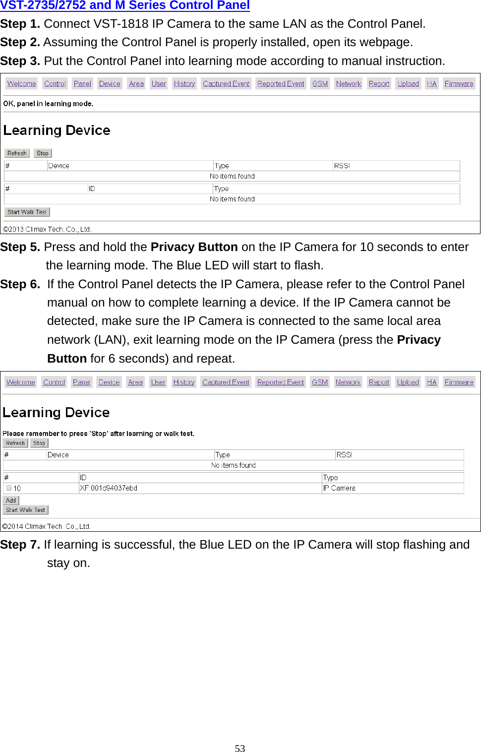
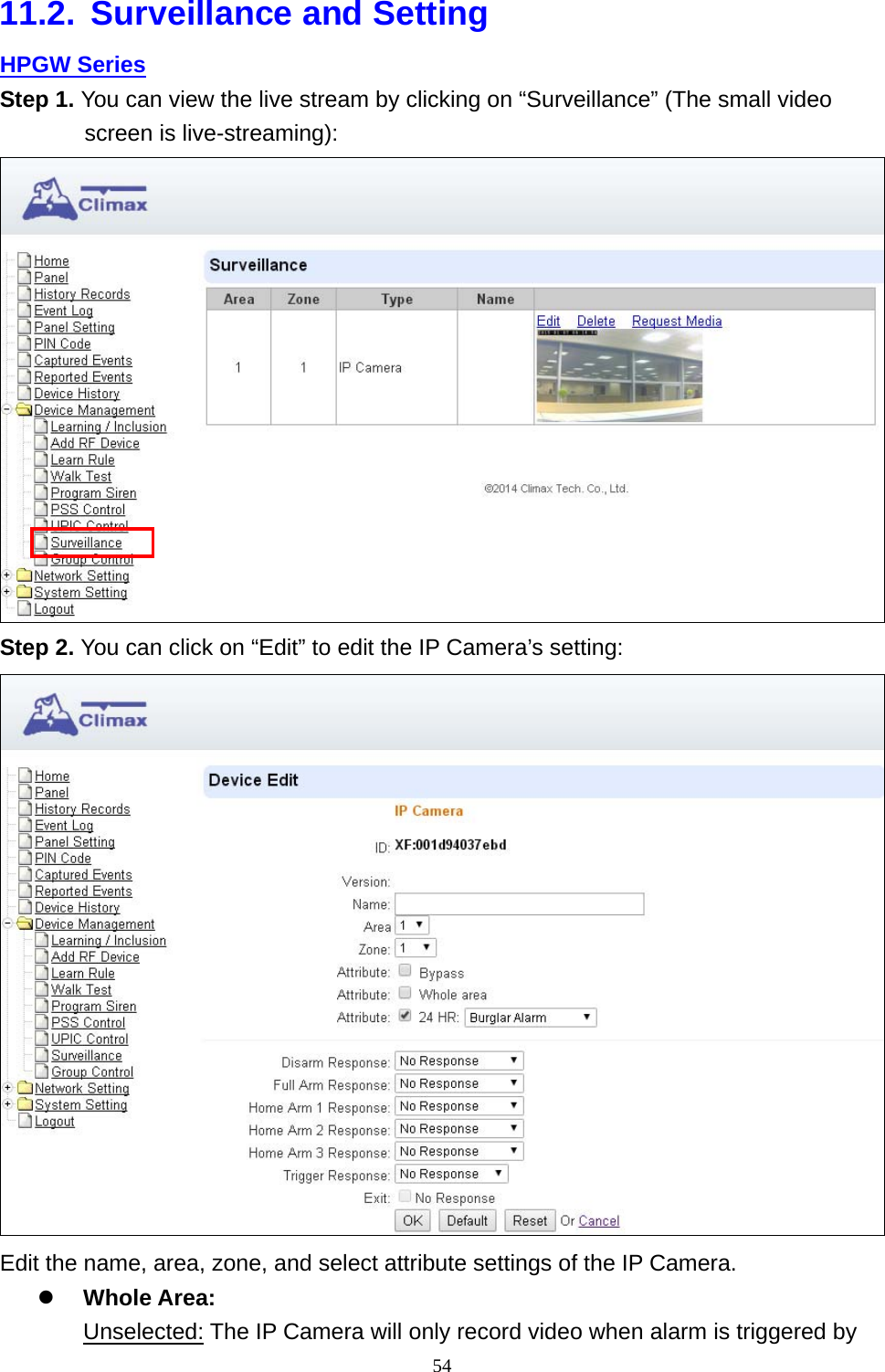
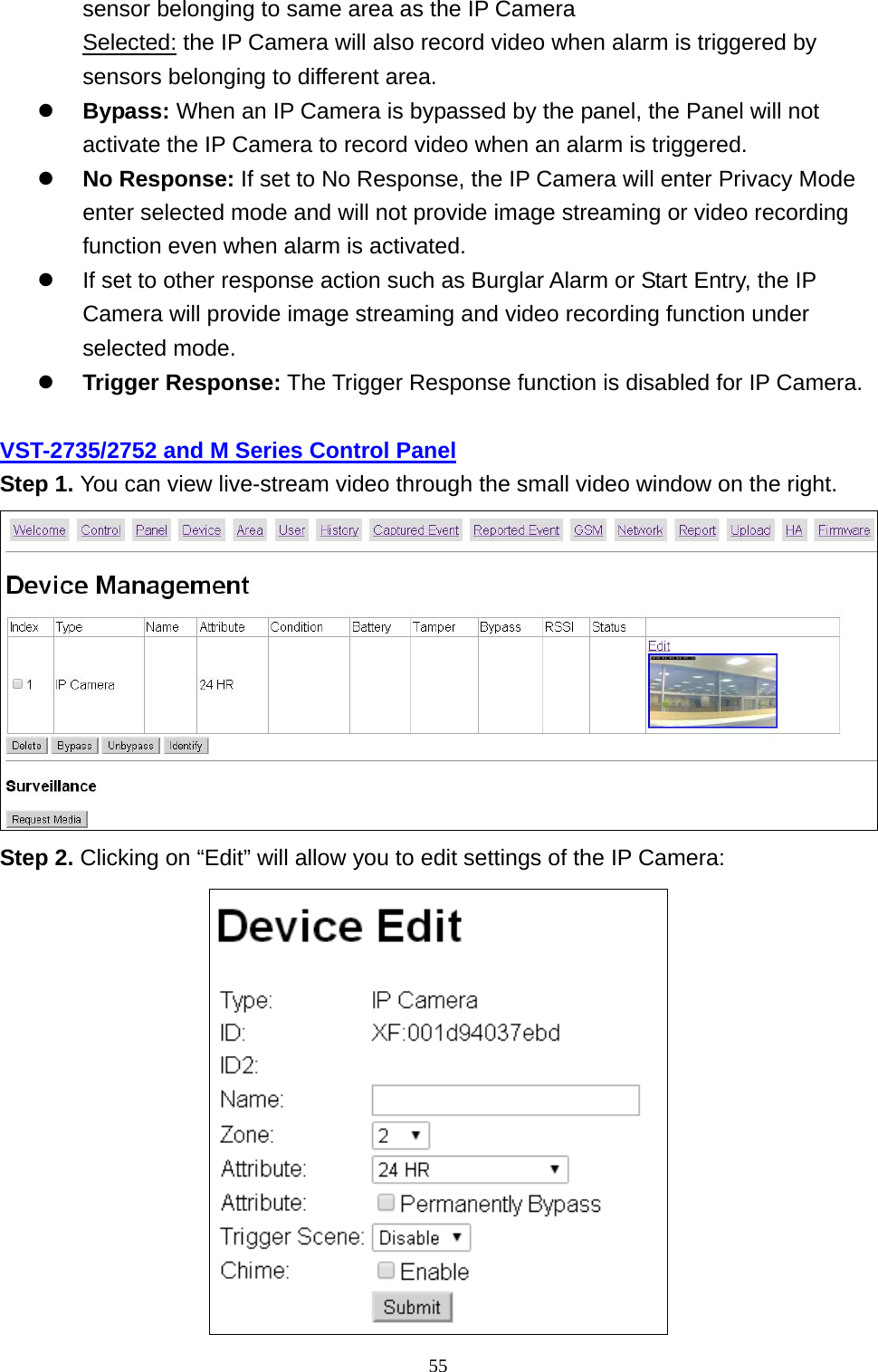
User Manual
Discussion / Help
Navigation