Climax Technology Co 2752 Smart Home Alarm System User Manual VST 2752 20140106
Climax Technology Co Ltd Smart Home Alarm System VST 2752 20140106
Users Manual
fCx
Jan-06-2014

Table of Contents
1. Application Overview __________________________________________________ 1
1.1. Identifying the Parts ______________________________________________________ 1
1.2. Introduction _____________________________________________________________ 2
1.3. The Power Supply ________________________________________________________ 2
1.4. How to Install the Control Panel ____________________________________________ 2
1.5. Three – Level Passwords __________________________________________________ 2
1.6. System Basic Operation ___________________________________________________ 3
1.7. Getting Started __________________________________________________________ 4
2. System Configuration _________________________________________________ 5
2.1. Walk Test _______________________________________________________________ 5
2.2. Install Code _____________________________________________________________ 5
2.3. Report Setting ___________________________________________________________ 5
2.4. Test Report _____________________________________________________________ 6
2.5. Record Message _________________________________________________________ 6
2.6. GSM Setting _____________________________________________________________ 6
2.7. Panel Setting ____________________________________________________________ 8
2.8. General Setting _________________________________________________________ 10
2.9. Device +/- ______________________________________________________________ 12
2.10. Network Setting ________________________________________________________ 15
2.11. Media Upload __________________________________________________________ 17
3. Programming Menu __________________________________________________ 18
3.1. Walk Test ______________________________________________________________ 18
3.2. PIN Code Setting ________________________________________________________ 18
3.3. Master Code ___________________________________________________________ 18
3.4. Temporary Code ________________________________________________________ 19
3.5. Duress Code ___________________________________________________________ 19
3.6. General Setting _________________________________________________________ 19
3.7. Device +/- ______________________________________________________________ 19
4. Operation __________________________________________________________ 20
4.1. LCD Display ____________________________________________________________ 20
4.2. Entering User Menu _____________________________________________________ 20
4.3. Away Arm Mode ________________________________________________________ 20
4.4. Home Arm 1/2/3 Mode ___________________________________________________ 21
4.5. Force Arm _____________________________________________________________ 21
4.6. Disarm ________________________________________________________________ 22
4.7. Bypass ________________________________________________________________ 22
4.8. Apply Scene ___________________________________________________________ 22
4.9. Dual Key Alarm _________________________________________________________ 22
4.10. Keypad Lockdown _____________________________________________________ 23
4.11. Tamper Protection _____________________________________________________ 23
4.12. Stop the Alarm and Alarm Display ________________________________________ 23
4.13. Voice Report and Call Acknowledgement __________________________________ 23
4.14. Fault Display __________________________________________________________ 24
4.15. Factory Reset _________________________________________________________ 24
4.16. Alarm Activation _______________________________________________________ 25
4.17. SMS Remote Command _________________________________________________ 27
5. Vesta EZ Home Application ____________________________________________ 32
5.1. For iPhone _____________________________________________________________ 32
5.2. For Android Phone ______________________________________________________ 40
6. Appendix ___________________________________________________________ 50
6.1. Event Code ____________________________________________________________ 50
1
1. Application Overview
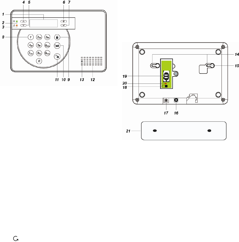
1.1. Identifying the Parts
1. Backlit LCD Display
2. Green LED
ON: AC Power is on.
FLASH: AC Power failure.
OFF: Power off
3. Yellow LED
ON: Fault Indicator; the Yellow LED will
light up when any fault situation is
detected and turn off when all fault
conditions are restored.
4. Key
— Use this key to move the cursor and
scroll the display upwards
5. Key
— Use this key to move the cursor and
scroll the display downwards.
6. Key
— Use this key for deleting a digit,
canceling the selection, aborting the
current screen and returning to the
previous screen etc.
7. OK Key
— To confirm the keyed-in data or
confirm the selection.
8. Numeric Keys
9. Away Arm Key
— Use this key to Away Arm the system.
10. Home Arm Key
— Use this key to Home Arm the system.
11. Disarm Key
— Use this key to Disarm the system.
12. Buzzer
13. Microphone
14. Mounting Holes & Tamper
15. Tamper Switch
16. DC Jack
— For connecting the DC 9V 1A power
adaptor.
17. Internet Connection
18. Battery Switch
19. SIM Card Base
20. GSM/GPRS LED
— On for 5 seconds when power is
supplied.
— Flash Slowly: GSM normal.
— Flash Quickly: GSM failure.
21. Wall Mounting Bracket
— For mounting the Control Panel on
the wall.

2
1.2. Introduction
VST-2752 Control Panel features both IP and
3G mobile network reporting functions:
The advanced IP Security System with fully
integrated TCP/IP technology and Ethernet
connectivity is able to take full advantage of
new advances in IP Home Security and Home
Automation and multi-path signalling.
SMS remote programming and command is
also available to configure your panel by SMS
messages. You can also use our Vesta EZ
Home smartphone applications to send the
SMS commands easily for basic panel
functions.
3G SIM card
The Control Panel features built-in 3G mobile
network facility to report to the Monitoring
Station. To use this function, a SIM card is
required.
<
<N
NO
OT
TE
E>
>
Please disable the SIM card PIN code
before inserting into the Control Panel.
Please make sure the SIM card data
transfer and MMS functions are
activated
Unlock the SIM card base by sliding the
cover toward OPEN direction.
Spring open the SIM card slot and insert
your new SIM card.
Replace the SIM slot onto the base lightly.
Remember to lock the SIM card base by
sliding the cover toward LOCK direction.
1.3. The Power Supply
An AC power adaptor is required to connect to
a wall outlet. Be sure only to use an adaptor
with the appropriate AC voltage rating to
prevent component damage.
A DC 9V output and 1A switching power is
generally used to power the Control Panel.
Rechargeable Battery
In addition to the adapter, there is a
rechargeable battery inside the
Control Panel that serves as a backup
powering source in case of any power
failure condition.
During normal operation, the AC
power adapter is used to supply
power to the Control Panel and at the
same time recharge the battery. It
takes approximately 72 hours to fully
charge the battery.
Battery Switch is set as OFF by
factory default, the battery will not be
charged when AC power is connected,
nor will it serve as a back-up power
source when AC power is missing.
You need to switch the battery to ON
after supplying AC power to Control
Panel.
1.4. How to Install the Control
Panel
The easiest way to get to know the system
and get it up and running quickly is to get
all the devices and accessories
programmed on a tabletop before locating
and mounting them.
The Control Panel can be mounted on the wall
or wherever desired. Ensure the Control Panel
is fitted at approximately chest height where
the display can be easily seen and the keypad
convenient to operate.
Step 1. Using the 2 holes of the Wall
Mounting Bracket as a template,
mark off the holes’ positions.
Step 2. Connect AC power adaptor, Ethernet
cable and insert SIM card.
Step 3. Hook the Control Panel onto the Wall
Mounting Bracket.
Step 4. Plug the AC power adaptor into wall
socket, the Control Panel Green LED
will light up along with 2 beeps to
indicate the panel is now operational.
1.5. Three – Level Passwords
In order to provide maximum security when
operating the system, the Control Panel offers
different levels of authorization for various
situations.

3
User PIN Code
The User Codes are used for users to
access the alarm system for basic alarm
system function. A total of 10 4-digit User
Codes can be stored in the Control Panel.
Each individual User can be given a
name for easy recognition when viewing
system events. User Names can be
named when first setting them or by
editing them afterwards when resetting
them.
User PIN code #1 is activated with “1234”
as factory default and cannot be deleted.
User PIN code #2~#10 are deactivated
by factory default
Whenever panel asks to key in Enter
Code or, please enter your User PIN
Code.
Master Code
The Master Code has the authorization to
enter Programming Mode for advanced
system setting. When the display panel
asks you to key in M-Code, please enter
your Master Code.
Factory default: 1111
Installer Code
The Installer Code is for installer to
program system configurations under
installer menu, such as Tel. Number,
Account Number.
When the display panel asks for I-Code,
please enter your Installer Code.
Factory default: 7982
Guard Code
The Guard Code has the same level of
authorization as the PIN Code. It is
designed for security personnel to access
the alarm system.
Temporary Code
The Temporary Code is designed for the
use of occasional visitors. It has the
same authorization level as the User PIN
Code, but will be removed after one
arming and disarming action.
Duress Code
The Duress Code is specially designed
for situation when the user is under
personal threat. It has the same level of
authorization as User PIN Code, however
when a Duress Code is entered, the
Control Panel will send a silent alarm
report to notify that the user is being
threatened or held against his will.
1.6. System Basic Operation
While entering PIN code, if incorrect
codes have been entered for 5 times.
The keypad input will be prohibited for 10
minute. Any key press during this 10-
minute period will reset the timer to 10
minutes.
When entering information for system
configuration, press key tol clear the
field, when the field is empty, press key
again to leave current screen, no
information will be saved.
When under user/programming/installer
menu, if no keys are pressed within 2
minutes, the panel will automatically exit
the menu and return to disarm mode.
If the Control Panel lost power supply.
When the power is restored, it will
resume its previoius mode.
When programming settings, refer to the
following tables to enter symbols and
alphabets, press the key repeatedly until
the desired symbol/alphabet appears.
1 1 , ! ? - 【 】 @ /
2 2 A B C a b c
3 3 D E F d e f
4 4 G H I g h i
5 5 J K L j k l
6 6 M N O m n o
7 7 P Q R S p q r s
8 8 T U V t u v
9 9 W X Y Z w x y z
0 0 <space> / - & ’ . +︰
Delete character and backspace

4
1.7. Getting Started
Step 1. Find a suitable location for the Control
Panel to be installed.
Step 2. Insert the SIM card in to GSM module
and connect the internet cable.
Step 3. Apply the AC Power. You will hear 2
short beep. Disarm will be displayed
on the first line and the system time
displayed on the second line of the
screen indicating the system is in
Disarm mode (Factory Default).
R e a d y t o A r m
0 0 : 0 1 J a n 0 1

5
2. System Configuration
In order to configure the Control Panel setting,
you need to enter the Installer Menu. To enter
the Installer Menu:
Step 1. Under Disarm mode, press any key on
the numeric keypad, you will be
prompted to enter User Menu.
E n t e r C o d e
.. .
Step 2. Enter a User PIN code (default is 1234)
then press OK to confirm. You will
enter User Menu
F a u l t D i s p l a y
L o g
A l a r m M e mo r y
B y p a s s
A p p l y S c e n e
A w a y Arm
H o me Arm 1
H o me Arm 2
H o me Arm 3
P - M e n u
I - M e n u
Step 3. Select I-Menu and press OK to confirm.
You will be prompt to enter Installer
Code.
E n t e r I - C o d e
. .. .
Step 4. Enter the Installer code (default is 7982)
and press OK to confirm. You will
enter the Installer Menu.
W
a l k T e s t
I n s t a l l C o d e
R p t n . S e t t i n g
T e s t R e p o r t
R e c o r d M s g
G S M S e t t i n g
P a n e l S e t t i n g
G e n . S e t t i n g
D e v i c e + / -
N e t w o r k S e t .
M e d i a U p l o a d
2.1. Walk Test
The Walk Test function allows you to test
learned in devices. (Please refer to 2.7 Device
+/- for device learning detail)
Step 1. Select Walk Test and press OK to
confirm. You will enter Walk Test
mode..
W
a l k T e s t
Step 2. Press the learn/test button on your
device to transmit a test code (please
refer to device manual for detail). If the
Control Panel receives the test code, it
will display the device information
accordingly.
2.2. Install Code
This function is for you to edit the Installer code
Step 1. Select Install Code and press OK to
confirm.
Enter I - C o de
. . . .
Step 2. Enter the new 4-digit Installer code
and press OK to confirm..
2.3. Report Setting
The Report Setting function allows you to
configure your report destinations. 8 reporting
detinations are available for configuration.
Step 1. Select Rptn. Setting and press OK to
confirm.
1)
2)
..
..
..
8)
Step 2. Select the reporting number you want
to program and press OK to confirm.
Step 3. Select the report type
GSM
SMS(C I D )
SMS(T E X T )
IP(SI A )
IP(CI D )
Mail
Voice
Delet e
GSM: DTMF digital reporting in CID
format through GSM.
SMS(CID): SMS reporting in CID
event code format.
SMS (Text): SMS reporting in text
message format.
IP(SIA): IP/GPRS reporting in SIA
format:

6
IP(CID): IP/GPRS reporting in CID
format.
Mail: Email reporting. (SMTP setting
required)
Voice: Voice message reporting.
Delete: Choose “Delete” to remove
existing report setting.
Step 4. For GSM/SMS(CID)/IP(CID/IP(SIA)
setting, you will be asked to enter an
account number.
Step 5. Enter the IP address for IP reporting,
email address for email reporting or
telephone/mobile number for
GSM/SMS reporting.
Step 6. For IP reporting, enter the port number.
Step 7. Select a group for the report
destination.
The reporting priority is based on to
group number sequence. From Group
1 Group Group 2 Group 3
….etc
When more than one reporting
destinations are assigned to a group,
if a report is sent to one of the
detinations successfully, the system
will stop reporting to the rest of the
reporting destination in the same
group and move on to report to the
next group.
If the Control Panel fails to send report
to the first detination in a group, it will
move on to the next reporting
destination. If all reporting destinations
in the group cannot be reached, the
Control Panel will move on to the next
group
If the Control Panel fails to report to all
reporting groups, it will start reporting
from group 1 and continue retrying
until one report is made successfully.
Step 8. Select the event type to be reported to
this report destination.
All: All events will be reported.
Status: Only status events will be
reported.
Alarm: Only alarm events will be
reported.
2.4. Test Report
This function is for you to test the reporting
destination you entered.
Step 1. Select Test Report and press OK to
confirm.
Step 2. The Control Panel will send a test
report to the first reporting destination.
2.5. Record Message
Use the function to record your Address
Message for Voice Report, the Address
Message is the first message played in every
voice report to notify the call recipient of the
caller’s information. The maximum length of
the message is 10 seconds.
Step 1. Select Record Msg and press OK to
confirm.
S t a r t R e c o r d i n g
(O K ? )
Step 2. Press OK to start recording.
R e c o r d i n g . . .
Pr ess O K t o st op
Step 3. The Control Panel will emit a beep.
Start recording after the beep, speak
clearly and slowly for the Control Panel
to record your address. When you
finish recording, press “OK” to stop
recording, the recording will
automatically stop when it reaches 10
second.
<
<N
NO
OT
TE
E>
>
If you do not record your own Address
Message, the system will play default
alarm message when reporting. The
default message is “Alarm System.”
2.6. GSM Setting
The GSM function allows you to program
GRPS network and MMS settings,
Step 1. Select GSM Setting and press OK to
confirm.
G P R S S e t t i n g
M M S S e t t i n g
G S M S i g n a l
G S M R e s e t

7
GPRS Setting
In order to use GPRS to serve as a back-up IP
Reporting method, this section will need to be
programmed before reporting.
Step 1. Select GPRS Setting and press OK to
confirm.
A P N
U s e r
P a s s
W
o r d
Step 2. Select APN and press OK to confirm.
A P N E d i t
i n t e r n e t
Step 3. Enter your APN(Access Point Name)
and press OK to confirm. Inquire your
service provider for information if
needed.
Step 4. Select User and press OK to confirm.
U s e r N a me
Step 5. Enter your log in user name and press
OK to confirm. Inquire your service
provider for information if needed.
Step 6. Select Password and press OK to
confirm.
P a s s w o r d
Step 7. Enter your log in password and press
OK to confirm. Inquire your service
provider for information if needed.
MMS Setting
MMS setting is required if you want to send
pictures/videos captured by PIR Camera or
PIR Video Camera to mobile phones.
Step 1. Select MMS Setting and press OK to
confirm.
A P N
U s e r
P a s s w o r d
U R L
P r o x y A d d r e s s
P o r t
Step 2. Select APN and press OK to confirm.
A P N E d i t
mms
Step 3. Enter your APN(Access Point Name)
and press OK to confirm. Inquire your
service provider for information if
needed.
Step 4. Select User and press OK to confirm.
U s e r N a me
Step 5. Enter your log in user name and press
OK to confirm. Inquire your service
provider for information if needed.
Step 6. Select Password and press OK to
confirm.
P a s s w o r d
Step 7. Enter you log in password and press
OK to confirm. Inquire your service
provider for information if needed.
Step 8. Select URL and press OK to confirm.
U R L
Step 9. Enter your MMS APN URL and press
OK to confirm. Inquire your service
provider for information if needed.
Step 10. Select Proxy Address and press OK
to confirm.
P r o x y A d d r e s s
Step 11. Enter your MMS Proxy Address and
press OK to confirm. Inquire your
service provider for information if
needed.
Step 12. Select Port and press OK to confirm.
P o r t
Step 13. Enter your MMS Port and press OK
to confirm. Inquire your service
provider for information if needed.
GSM Signal
GSM Signal function displays your current
GSM strength in RSSI value,
Step 1. Select GSM Signal and press OK to
confirm.
G S M S i g n a l
RSS I = 9
Step 2. The screen will display GSM strength
in RSSI value from 1 to 9.
GSM Reset
This is for you to reset your GSM module.
Step 1. Select GSM Reset and press OK to
confirm.
A r e y o u s u r e ?
Step 2. The screen will ask you to confirm the
action, press OK of you want to reset
GSM.

8
Step 3. The GSM module will be reset.
2.7. Panel Setting
The Panel Setting menu allows you to program
Control Panel configurations.
Step 1. Select Panel Setting and press OK to
confirm.
K e y w o r d
P - w o r d
A C F a i l R e p o r t
J a mmi n g r e p o r t
A u t o c h e c k - i n
O f f s e t p e r i o d
F o l l o w - o n T i me
H i g h T e mp R p t
L o w T e mp R p t
B y p a s s F a u l t
D a t e & T i me
Keyword
The Keyword is used for receiving SMS
commands from users. When a user sends a
SMS command to the Control Panel, the
correct keyword must be entered along with a
valid User PIN code for the Control Panel to
recognize the command. The Keyword is
disabled by default.
Step 1. Select Keyword and press OK to
confirm.
K e y w o r d
Step 2. The screen will display current
Keyword. Enter the new keyword if you
want to edit keyword, press OK to
confirm the change.
P-word
The P-word is also used for receiving SMS
commands from Installers. When an installer
sends a SMS command to the Control Panel,
the correct P-word must be entered along with
Installer code for the Control Panel to
recognize the command. The P-word is
“PROG" by default.
Step 1. Select P-word and press OK to
confirm.
P -
W
o r d
P R O G
Step 2. The screen will display current P-word.
Enter the new keyword if you want to
edit keyword, press OK to confirm the
change.
AC Fail Report
This is for you to set the waiting time for the
Control Panel to make report after detecting
AC failure. Factory default is set to 5 minutes.
Step 1. Select AC Fail Report and press OK
to confirm.
Disabl e
1 min
2 min
3 min
4 min
5 min
Step 2. The screen will display current AC fail
report setting. To change the setting,
select a new option and press OK to
confirm.
Jamming Report
This is for you to set whether the Control Panel
should detect radio frequency interference and
make report when interference is detected.
Factory default is set to On. When radio
jamming is detected, the Control Panel will
report the event accordingly. Factory default is
turned Off.
Step 1. Select Jamming report and press OK
to confirm.
Off
On
Step 2. Select to turn on/off the Jamming
report function and press OK to
confirm.
Auto check-in
This is for you to set the interval time the
Control Panel waits before making a regular
check-in report to the programmed reporting
destination. Factory Default is set to 12 hours.
Step 1. Select Auto check-in and press OK to
confirm.
Disab l e
4 hr
8 hr
12 hr
16 hr
20 hr
24 hr
Step 2. The screen will display current Auto
check-in setting. To change the setting,
select a new option and press OK to
confirm.
Offset Period
This is to set the time delay before the first

9
Auto check-in report is made whenever the
Control Panel was powered off, then on again,
or when Auto check-in interval time is changed..
Factory Default is set to 1 hour.
Step 1. Select Offset period and press OK to
confirm.
1 h r
2 h r
. . .
1 1 h r
1 2 h r
Step 2. The screen will display current Offset
period setting. To change the setting,
select a new option and press OK to
confirm.
Follow-on Timer
After the Control Panel makes a GSM digital
report to the Central Monitoring Station, the
Central Monitoring Station can choose to enter
a “Listen-in” period according to the Follow-On
timer duration set here. During this period, the
Central Monitoring Station will be able to listen
to what is happening around the Control Panel
through the microphone on the panel.
Step 1. Select Follow-on Time and press OK
to confirm.
D i s a b le
1 mi n
3 mi n
5 mi n
N o L i mi t
Step 2. The screen will display current Follow-
on Timer setting. To change the setting,
select a new option and press OK to
confirm.
High Temperature Report
This is for you to set the High Temperature
reporting threshold. If the Control Panel has
learnt in a Temperature Sensor, it will make
High Temperature report and raise alarm when
the temperature exceeds the threshold. When
the temperature drops below set value again,
the Control Panel will stop alarming and send
High Temperature Restore report. Factory
default is set to Disable.
Step 1. Select High Temp and press OK to
confirm.
D i s a b le
- 1 0 ° C
0 ° C
. . .
. . .
50 °C
Step 2. The screen will display current High
Temperature alarm setting. To change
the setting, select a new option and
press OK to confirm.
Low Temperature Report
This is for you to set the Low Temperature
reporting threshold. If the Control Panel has
learnt in a Temperature Sensor, it will make
Low Temperature report and raise alarm when
the temperature drops below the threshold.
When the temperature rises above set value
again, the Control Panel will stop alarming and
send Low Temperature Restore report. Factory
default is set to Disable.
Step 1. Select Low Temp and press OK to
confirm.
Disab l e
- 10 ° C
0 °C
...
...
50 °C
Step 2. The screen will display current Low
Temperature alarm setting. To change
the setting, select a new option and
press OK to confirm.
Bypass Fault
This is for you to set whether you want to
ignore fault events regarding Ethernet or GSM
function. Bypassed fault events will not
displayed or cause the fault LED will to light up
and emit beeps.
Step 1. Select External Tamper and press OK
to confirm.
Disabl e
IP
GSM
Step 2. Select either disable/IP/GSM and
press OK to confirm.
Date & Time
This is for you to set your time zone, date and
time.
Step 1. Select Date & Time and press OK to
confirm.
T i me Z o n e
Date & T i me
Step 2. The screen will display current time
zone and date/time setting. To change
the time zone, select Time Zone and

10
press OK.
U T C
L o s A n g e l e s
D e n v e r
C h i c a g o
N e w Y o rk
M o n c t o n
L o n d o n
P a r i s
I s t a n b u l
M o s c o w
T a i p e i
T o k y o
S y d n e y
A u c k l a n d
Step 3. The screen will display current time
zone setting, To change the setting,
select a new option and press OK to
confirm.
Step 4. Select Date & Time to edit Control
Panel date and time.
D a t e & T i me
2 0 1 3 / 0 3 / 2 2 / 0 9 : 1 1
Step 5. The current date and time will be
displayed, you will begin by editing
year. Press Up or Down button to
change current year, press OK to
continue to edit month/date/hour/
minute.
2.8. General Setting
The General Setting menu allows you to
program Control Panel’s alarm related settings
Step 1. Select Gen. Setting and press OK to
confirm.
F i n a l D o o r
A r m F a u l t T y p e
T a mp e r A l a r m
E n t r y T i me
E x i t T i me
A l a r m L e n g t h
S u p e r v i s i o n
S o u n d S e t t i n g
Final Door
If set to On, when the system is Away Armed
with a Door Contact set to Entry attribute, the
system will automatically arm the system once
the Door Contact is closed even if the entry
delay timer has not expired yet.
If set to Off, When the system is Away Armed
with a Door Contact set to Entry attribute, the
system will only arm the system after the entry
delay timer expires. (Factory Default)
Step 1. Select Final Door and press OK to
confirm.
Off
On
Step 2. Select to turn On or Off the Final Door
option.
Arm Fault Type
Confirm: When set to Confirm, If you attempt
to arm when a fault exists within the system,
the arming action will be prohibited, and a
message will be displayed “Fault exists! Please
Confirm!” You need to arm the system again to
confirm your action and arm the system.
(Factory Default)
Direct Arm: When set to Direct Arm, If you
attempt to arm when a fault exists within the
system, the system will enter selected arm
mode without further notification about fault
events.
Step 1. Select Arm Fault Type and press OK
to confirm.
Confi r m
Direc t A r m
Step 2. Select either Confirm or Direct Arm,
and press OK to confirm.
Tamper Alarm
Away Arm: Tamper alarm will only be
activated when tamper switch is triggered
under Away Arm mode (Tamper event will still
be reported normally in Home/Disarm mode).
(Factory Default)
Always: Tamper alarm will be activated
whenever tamper switch is triggered.
Step 1. Select Tamper Alarm and press OK to
confirm.
Away A r m
Alway s
Step 2. Select either Away Arm or Always, and
press OK to confirm.
Entry Time
If a device set to Entry attribute is triggered
when the system is armed, the Control Panel
will begin an Entry Delay countdown timer
according to your Entry Time setting. The
system must be disarmed before the timer
expires or an alarm will be activated. The Entry
Timer for Away Arm/Home Arm 1/Home Arm 2/
Home Arm 3 can be programmed separately.
(Factory Default is 10 seconds)
Step 1. Select Entry Time and press OK to

11
confirm.
A w a y A r m
H o me A r m 1
H o me A r m 2
H o me A r m 3
Step 2. Select an arm mode to edit its Entry
Time, press OK to confirm.
D i s a b l e
1 0 s e c
. . .
. . .
7 0 s e c
Step 3. The screen will display current setting.
To change the setting, select a new
option and press OK to confirm..
Exit Time
When you arm the system, the Control Panel
will begin an Exit Delay countdown timer
according to your Exit Time setting, and enter
selected arm mode after the timer expires.
(Factory Default is 10 seconds)
Step 1. Select Exit Time and press OK to
confirm.
A w a y A r m
H o me A r m 1
H o me A r m 2
H o me A r m 3
Step 2. Select an arm mode to edit its Exit
Time, press OK to confirm.
D i s a b l e
1 0 s e c
. . .
. . .
7 0 s e c
Step 3. The screen will display current setting.
To change the setting, select a new
option and press OK to confirm..
Alarm Length
When an alarm is activated, both the
Control Panel siren and external siren
will raise alarm according to the Alarm
Length setting. (Factory Default is 3
minutes.)
Step 1. Select Alarm Length and press OK to
confirm.
D i s a b l e
1 mi n
. . .
. . .
1 5 mi n
Step 2. The screen will display current setting.
To change the setting, select a new
option and press OK to confirm.
Supervision
Set the supervision timer for accessory devices,
if no supervision signal is received within set
duration for a certain device, the Control Panel
will report the situation accordingly. (Factory
Default is 12 hour)
Step 1. Select Supervision and press OK to
confirm.
Disabl e
4 hr
6 hr
...
...
1 day
Step 2. Select your desired Supervision time,
press OK to confirm.
Sound Setting
This function allows you to program various
sound
Step 1. Select Sound Setting and press OK to
confirm.
Door C h i me
Entry A r m
Entry H o me
Exit A r m
Exit H o me
W
a r n i n g B e e p
Step 2. Select the function you want to edit
and press OK to confirm. Available
options include:
Off
Low
Medium
High
Door Chime: If not turned off, the
Control Panel will sound a door chime
sound when a Door Contact set to
Entry attribute is activated in Disarm
mode.
Entry Arm: If not turned off, the
Control Panel will sound beeping
sounds when a Door Contact set to
Entry attribute is activated in Away
Arm mode.
Entry Home: If not turned off, the
Control Panel will sound beeping
sounds when a Door Contact set to
Entry attribute is activated in Home
Arm mode.

12
Exit Arm: If not turned off, the Control
Panel will sound beeping sounds
when during Exit Delay Timer for
Away Arm mode.
Exit Home: If not turned off, the
Control Panel will sound beeping
sounds when during Exit Delay Timer
for Away Arm mode.
Warning Beep: If not turned off, the
Control Panel will sound beeping
sounds every 30 seconds when fault
exists within system.
2.9. Device +/-
Devices +/- menu allows you to
add/change/delete all available devices. A total
of 40 devices can be included in the Control
Panel.
Step 1. Select Device +/- and press OK to
confirm.
A d d D e v i c e
E d i t D e v i c e
R e mo v e D e v i c e
P r o g r a m S i r e n
Add Device
Use this function in include new device into the
Control Panel.
Step 1. Select Add device +/- and press OK
to confirm.
P u s h B u t t o n O n
D e v i c e t o A d d
Step 2. Press the learn button on the device
you want to learn in to transmit a learn
code, please refer to the device
manual for detail.
Step 3. If the learning code is received
successfully by the Control Panel, the
device information will be displayed on
the LCD screen. Press OK to add the
device into Control Panel.
D e t e c t e d ( O k ? )
D o o r C o n t a c t
Step 4. Repeat Step 1~3 to learn in other
devices.
Edit Device
Use this function edit the devices learnt into the
Control Panel in Add Device.
Step 1. Select Edit device +/- and press OK to
confirm.
Step 2. Devices that have already been learnt
in will be displayed along with their
zone number (Z01, Z02…etc).
DC Z01
IR Z02
<
<N
NO
OT
TE
E>
>
The available of devices are listed as
followings:
Door Contact --- DC
PIR Sensor --- IR
Pet Immune PIR Sensor--IRP
External PIR - -EIR
Remote Controller --- RC
Carbon Monoxide --- CO
Smoke Detector --- SD
Water Sensor --- WS
Panic Button --- PB
Night Switch --- NS
Remote Keypad --- KP
Indoor Siren --- SR
Outdoor Bellbox --- BX
Power Switch --- PSS
Power Swich Meter --- PSM
PIR Camera --- SV
Step 3. Step the device you want to edit, press
OK to confirm.
Burgla r
Home O mi t
Home1/ 2 O mi t
Home1/ 3 O mi t
H o me A c c e s s
D e l a y Z o n e
Away O n l y
Entry
A w a y E n t r y
24 HR
Fire
M e d i c a l / E mg .
W
ater
Set/Un s e t
Silent P a n i c
P e r s o n a l A t t .
Step 4. You will enter attribute setting page for
the device. The device attribute
determines this device’s behavior,
please refer to attribute list below to

13
select an attribute, Factory Default is
set to Entry for Door Contact and PIR
Sensor
Burglar
When the system is in any Arm
mode, if a “Burglar” device is
triggered, a “Burglar Alarm” will
be activated immediately and
reported.
Home Omit
When the system is in Home
Arm 1/2/3 mode, if a “Home
Omit” device is triggered, the
Control Panel will not raise
alarm. It will still send a report
for this event
When the system is in Full Arm
mode, if a “Home Omit” device
is triggered, the Control Panel
will respond in the same way as
if a “Burglar” device is triggered.
Home 1/2 Omit
When the system is in Home
Arm 1/2 mode, if a “Home 1/2
Omit” device is triggered, the
Control Panel will not respond. It
will still send a report for this
event
When the system is in Away
Arm or Home Arm 3 mode, if a
“Home 1/2 Omit” device is
triggered, the Control Panel will
respond in the same way as if a
“Burglar” device is triggered.
Home 1/3 Omit
When the system is in Home
Arm 1/3 mode, if a “Home 1/3
Omit” device is triggered, the
Control Panel will not respond. It
will still send a report for this
event
When the system is in Away
Arm or Home Arm 2 mode, if a
“Home 1/2 Omit” device is
triggered, the Control Panel will
respond in the same way as if a
“Burglar” device is triggered.
Home Access
When the system is in Home
mode, if a “Home Access”
device is triggered, the Control
Panel will start an Entry Delay
period to give enough time to
disarm the system. It will also
send a report for this event
When the system is in Full Arm
mode, if a “Home Access”
device is triggered, the Control
Panel will start a Burglar Alarm
and a burglar message will be
reported.
Delay Zone
When the system is in any Arm
mode, if a “Delay Zone” device
is triggered, a “Burglar Alarm”
will be activated immediately
and reported.
When the system is in any
Armed mode, and the Control
Panel is counting down the
Entry Delay, if a “Burglar”
device is triggered, the Control
Panel will not respond.
During the Exit Delay period, if a
“Burglar” device is triggered,
the Control Panel will not
respond .
Away Only
When the system is in Away
Arm mode, if an “Away Only”
device is triggered, a “Burglar
Alarm” will be activated
immediately and reported.
When the system is in any
Home Arm mode, if an “Away
Only” device is triggered, the
Control Panel will not respond.
During the Entry Delay or Exit
Delay period, if an “Away Only”
device is triggered, the Control
Panel will not respond .
Entry
When the system is in any Arm
mode, if an “Entry” device is
triggered, the Control Panel will
start an Entry Delay countdown
timer for the user to disarm the
system.
After the delay period has

14
expired and no correct PIN code
has been entered, the Control
Panel will activate its built-in
siren immediately to remind the
user the delay period has
expired.
If the Control Panel is not
disarmed within 30 seconds
after the delay period expires, a
Burglar Alarm will be reported
and the external sirens included
in the Control Panel will also be
activated. Disarming the Control
Panel within the 30 second
period will return the system to
Disarm mode and silence the
built-in siren. No alarm event will
be reported.
When the system is in Disarm
mode, if a “Entry” is triggered,
the Control Panel will make a
“ding-dong” Door Chime sound
(if Door Chime function is not
disabled).
Away Entry
When the system is in Away
Arm, if an “Away Entry” device
is triggered, the Control Panel
will start an Entry Delay
countdown timer for the user to
disarm the system.
After the delay period has
expired and no correct PIN code
has been entered, the Control
Panel will activate its built-in
siren immediately to remind the
user the delay period has
expired.
If the Control Panel is not
disarmed within 30 seconds
after the delay period expires, a
Burglar Alarm will be reported
and the external sirens included
in the Control Panel will also be
activated. Disarming the Control
Panel within the 30 second
period will return the system to
Disarm mode and silence the
built-in siren. No alarm event will
be reported.
When the system is in Disarm
mode, if a “Entry” is triggered,
the Control Panel will make a
“ding-dong” Door Chime sound
(if Door Chime function is not
disabled).
When the system is in any
Home Arm mode, if an “Away
Entry” device is triggered, the
Control Panel will not respond.
During the Entry Delay or Exit
Delay period, if an Away Entry
device is triggered, the Control
Panel will not respond
24 Hour
The 24 Hour device is active all
the time and does not have to
be armed or disarmed. An Event
Code of #130 will be reported
with trigger.
Fire
The Fire device is active all the
time and does not have to be
armed or disarmed. An Event
Code of #111 will be reported
with trigger.
Medical Emergency
A Medical Emergency device
is active all the time and does
not have to be armed or
disarmed. An Event Code of
#101 will be reported with trigger.
Water
The Water device is active all
the time and does not have to
be armed or disarmed. An
Event Code of #154 will be
reported with trigger.
Set/Unset (For Door Contact Only)
If the Door Contact is set to
Set/Unset, the system will be
disarmed when the Door
Contract is triggered, and armed
when Door Contact is closed.
Silent Panic
If the device attribute is set as
Silent Panic, when the device
is activated, the Control Panel
will report a Slient Panic alarm
without sounding an audible

15
siren. An event code of 122 will
be reported.
Personal Attack
If the device attribute is set as
Personal Attack, when the
device is activated, the Control
Panel will activate an alarm and
report an event code of 120 will
be reported.
Step 5. Select if you want to permanently
bypass the device. Permanently
Bypass will deactivated selected
device until you unselect the function.
The Control Panel will ignore all signal
sent from Permanently Bypassed
device, include Low Battery and
Tamper signal. Press OK to confirm.
Factory Default is Normal.
N o r ma l
P e r ma n . B y p a s s
Step 6. Select to on or off latch report. When
turned on, the Control Panel will send
a report if the device is triggered.
Press OK to confirm.
L a t c h R p t O f f
L a t c h R p t O n
Step 7. Enter a name for the device, press OK
to confirm.
E d i t n a me
Remove Device
Use this function remove a leant in device.
Step 1. Select Remove Device +/- and press
OK to confirm.
Step 2. The screen will display learnt in device
list. Select the device you want to
remove, press OK to confirm.
Program Siren
The program siren functions allows you to
learn in siren/bellbox and program their
behaviour.
L e a r n S i r e n
S i r e n T a mp . O n
S i r e n T a mp . O f f
C o n f i r m O n
C o n f i r m O f f
E n t r y S n d . O n
E n t r y S n d . O f f
Learn Siren: In order to learn a Siren
into the Control Panel, the Control
Panel must first learn in a device of
any kind.
Step 1. Put the siren into learning mode,
please refer to the Siren manual for
detail.
Step 2. Select Learn Siren, press OK to
confirm.
Step 3. The Control Panel will transmit learning
code to the siren. If the siren receives
the learn code, it will react accordingly,
please refer to your siren manual for
detail.
<
<N
NO
OT
TE
E>
>
For SR-15 or BX-15, please learn in
the siren according to the instruction
in Add Device.
Siren Tamper On/Off
Siren Tamp.On: When selected, the Siren’s
tamper protection will be enabled.
Siren Tamp.Off: When selected, the Siren’s
tamper protection will be disabled.
Confirm On/Off
Confirm On: When selected, the Siren will
emit beeping sound when the system is armed
or disarmed.
Confirm Off: When selected, the Siren will not
emit beeping sound when the system is armed
or disarmed.
Entry Sound On/Off
Entry Snd.On: When selected, the Siren will
emit beeping sound during Entry Delay
countdown timer
Entry Snd.On Off: When selected, the Siren
will not emit beeping sound during Entry Delay
Countdown Timer
2.10. Network Setting
Program your network and email SMTP setting
under this menu.
Step 1. Select Network Setting, press OK to
confirm
Curren t I P
DHCP
I P A d d r e s s
S u b n e t M a s k
Ga t ewa y
DNS
SNTP

16
I n t e r v a l
S M T P
F r o m
Current IP
The Control Panel’s current local area network
IP will be displayed
DHCP
On: If DHCP is set to On, the Network will
obtain the IP address automatically with a valid
Network DHCP Server. You do not need to do
any settings. You can only set DHCP to On if
your Network environment supports DHCP. It
will automatically generate all network
information.
Off: If DHCP is set to Off, you neet to enter the
Network information manually for IP Address,
Subnet mask, Gateway, and DNS. Please
make sure that you have obtained all required
values for your Network environment. Contact
local service provider if necessary
IP Address/Subnet Mask/Gateway/DNS
You only need to configure these settings if
DHCP is set to Off.
Step 1. To edit the setting, select the option to
edit and press OK to confirm..
Step 2. Enter a new setting, press OK to
confirm.
SNTP
The SNTP setting is for you to enter an internet
time server IP to synchronize and update
Control Panel time automatically according to
set interval time. Factory Default is:
pool.ntp.org.
Step 1. To edit the setting, select t SNTP and
press OK to confirm..
Step 2. Enter a new IP Address if desired,
press OK to confirm.
I P A d d r e s s
p o o l . n t p . o r g
Interval
Set the interval time for SNTP setting to update
Control Panel time
Step 1. To edit the setting, select t Interval and
press OK to confirm.
Step 2. Select your desired interval time, press
OK to confirm..
4 h o u r
8 h o u r
1 2 h o u r
16 hou r
20 hou r
24 hou r
SMTP
The SMTP setting is for you to program the
mail server related settings. The email account
you set here would be used to email the
triggered images/videos from PIR
Camera/Video Camera. For email destination,
please refer to Media Upload section.
Step 1. To edit the email information, select
SMTP and press OK to confirm.
Step 2. Enter your SMTP setting, press OK to
confirm.
SMTP
The format of SMTP setting is:
smtp://user:password@mail server
User: email account user name. For example,
if your email account is john@yahoo.com,
enter john.
Password: email account password.
Mail Server: Email server domain name.
The default port used by SMTP is Port 25. If
you want to specify other ports, enter the port
number according to format below:
smtp://user:password@mail server:port
<
<N
NO
OT
TE
E>
>
The control panel does not support
encryption method such as SSL/TLS.
SMTP setting must be entered in all
lowercase letters
From
This is for you to set the email account used to
send captured picture/video. This setting
should be entered along with SMTP setting.
Step 1. To edit the email information, select
From and press OK to confirm.
Step 2. Enter the email account according to
SMTP setting. Ex: john@yahoo.com.,
press OK to confirm.
E ma i l a c c o u n t
<
<N
NO
OT
TE
E>
>
The format of From setting is:
name@example.com

17
From setting must be entered in all
lowercase letters
2.11. Media Upload
The Media Upload menu allows you to set the
destination for the Control Panel to deliver
captured picture/video from PIR Camera or
PIR Video Camera.
Step 1. To edit the setting, select Media
Upload and press OK to confirm.
1 )
2 )
3 )
4 )
5 )
P r e f i x
1~5
There are 5 upload destinations available for
you to program.
Step 1. Select one of the upload destination
from 1~5, press ok to confirm.
Step 2. Select to either edit or delete the
setting, press OK to confirm..
E d i t
D e l e t e
Step 3. If you choose to edit the setting, enter
an email address, FTP address, or
mobile number for MMS delivery.
Email: In order to sent the
picture/video by email, the SMTP and
From setting must be completed first.
The email upload format is: mailto:
user@example.com
MMS: In order to sent the
picture/video to a mobile number the
MMS setting must be completed first.
The MMS upload format is: mms:
mobile number
FTP: The FTP upload format is:
ftp://user:password@IP address:port/
folder
If you choose to delete the setting, the
current upload setting will be removed
Step 4. If you choose to edit the setting, enter
an email address, FTP address, or
mobile number for MMS delivery.
Prefix
The prefix is the title given to every captured
picture or video for you to identify the file.
Step 1. Select Prefix, press OK to confirm.
Step 2. Select to either edit or delete the
setting, press OK to confirm..
Edit
Delete
Step 3. If you choose to edit the setting, enter
a new title and press OK to confirm.
If you choose to delete the setting, the
current Prefix will be removed

18
3. Programming Menu
The programming menu is designed for user to
mange User PIN codes and other setting. to
enter the Programming Menu:
Step 1. Under Disarm mode, press any key on
the numeric keypad, you will be
prompted to enter User Menu.
E n t e r C o d e
.. .
Step 2. Enter a User PIN code (default is 1234)
then press OK to confirm. You will
enter User Menu
F a u l t D i s p l a y
L o g
A l a r m M e mo r y
A w a y Arm
H o me Arm 1
H o me Arm 2
H o me Arm 3
P - M e n u
I - M e n u
Step 3. Select P-Menu and press OK to
confirm. You will be prompt to enter
Installer Code.
E n t e r M - C o d e
. .. .
Step 4. Enter the Master code (default is 1111
and press OK to confirm. You will
enter the Installer Menu.
W
a l k T e s t
P i n C o d e
M a s t e r C o d e
T e mp C o d e
D u r e s s C o d e
G e n . S e t t i n g
D e v i c e + / -
3.1. Walk Test
The Walk Test function under Programming
Menu functions the same as the Walk Test
function in Installer Menu. Please refer to 2.1.
Walk Test for detail.
3.2. PIN Code Setting
The User Codes are used for users to acess
the alarm system. A total of 10 4-digit User
Codes can be stored in the Control Panel.
Each individual User can be given a name for
easy recognition User PIN Code #1 is set to
1234 by Factory Default.
Step 1. Select Pin Code, press OK to confirm.
Step 2. You will enter the PIN code menu.
Select the PIN code you want to edit,
then press OK to confirm.
1)
2)....
...
...
...
9)....
10)... .
Step 3. For an existing PIN code, you will be
asked whether you want to delete the
PIN code (except for PIN code 1 which
cannot be deleted), press OK to
confirm if you want to delete the PIN
code
For an empty PIN code, you will be
prompted to enter a new code.
E n t e r n e w c o d e
. . . .
Step 4. Select a new PIN code and press OK,
you will be asked to repeat the code
again.
R e p e a t n e w c o d e
. . . .
Step 5. Select to turn on/off Latch option.
When set to On, the system will report
all arm/disarm action by this user.
Press OK to confirm.
User N a me
Step 6. Enter a User Name for this PIN Code,
you can also leave this field blank.
Press OK to confirm. The PIN code
setting is now complete.
3.3. Master Code
The Master Code is used to access the
Programming Menu. Factory Default is set to
1111. To change the Master Code.
Step 1. Select Master Code and press OK to
confirm. You will be prompt to enter a
new Master Code.
E n t e r n e w c o d e
. . . .
Step 2. Enter the new code and press OK, you
will be asked to repeat the code again.

19
R e p e a t n e w c o d e
. .. .
Step 3. Repeat the new code and press OK to
confirm. Master Code setting is now
complete.
3.4. Temporary Code
The Temporary Code is used to access the
system for a temporary user and is valid only
once per arming and once per disarming.
Afterwards, the Temporary Code is
automatically erased and needs to be reset for
a new Temporary user. To set the Temporary
Code.
Step 1. Select Temp Code and press OK to
confirm. You will be prompt to enter a
new Temporary Code.
E n t e r n e w c o d e
. .. .
Step 2. Enter the new code and press OK, you
will be asked to repeat the code again.
R e p e a t n e w c O d e
. .. .
Step 3. Repeat the new code and press OK to
confirm. Temporary Code setting is
now complete.
3.5. Duress Code
The Duress Code has the same function as the
User PIN code. It is used to access the system
in duress situation. When this code is used for
accessing the system, the Control Panel will
report a secret alarm message without
sounding the siren to the Central Monitoring
Station to indicate of a “Duress Situation in
Progress”. To set the Duress Code:
Step 1. Select Duress Code and press OK to
confirm. You will be prompt to enter a
new Duress Code.
E n t e r n e w c o d e
. .. .
Step 2. Enter the new code and press OK, you
will be asked to repeat the code again.
R e p e a t n e w c O d e
. .. .
Step 3. Repeat the new code and press OK to
confirm. Duress Code setting is now
complete.
3.6. General Setting
The General Setting function under
Programming Menu functions the same as the
General Setting function in Installer Menu.
Please refer to 2.6. General Setting for detail.
3.7. Device +/-
The Device +/- function under Programming
Menu functions the same as the Device +/-
function in Installer Menu. Please refer to 2.7.
Device +/- for detail.

20
4. Operation
4.1. LCD Display
The Control Panel’s LCD will display the
system information according to different status
and panel modes.
Disarm mode
When the system is in Disarm mode, and no
fault exists in system, the LCD will display
“Ready to Arm”.
R e a d y t o A r m
0 0 : 0 1 J a n 0 1
When fault events exists in system, The LCD
will display the fault event on screen, followed
by “(XX)”. The XX represents the number of
fault event in system.
When Control Panel or accessory tamper open
status is detected, the LCD will display
“Tamper Zone”
T a m p e r Z o n e ( X X )
0 0 : 0 1 J a n 0 1
When Door Contact in the system is opened
(not aligned with magnet), the LCD will display
“Open Zone”
O p e n Z o n e ( X X )
0 0 : 0 1 J a n 0 1
When other fault exists in system, the LCD will
display “Fault”
F a u l t ( X X )
0 0 : 0 1 J a n 0 1
Away Arm / Home Arm mode
When the system is in Away Arm or Home Arm
mode, and no fault event exists in system, the
LCD will display current mode.
A w a y A r m
0 0 : 0 1 J a n 0 1
When the system is in Away Arm or Home Arm
mode, and fault event exists in system, the
LCD will display (XX) after current mode. The
XX represents the number of fault event in
system.
A w a y A r m ( X X )
0 0 : 0 1 J a n 0 1
View Fault Events
When fault event exists in system, press Down
key to view fault events.
Step 1. The screen will display:
ST A R T
Step 2. Press Down key to scroll through the
fault events. When all fault events are
displayed, the screen will show:
E N D
Step 3. Press key to exit fault display.
4.2. Entering User Menu
When the system is in Disarm mode, enter a
valid user code to access the User Menu,
When the first numberic key is pressed, the
display will show:
E n t e r C o d e
. . . .
Enter the 4-digit user PIN code followed by OK,
within 30 sec.
The options are available for user menu:
oFaul t D i s p l ay
Log
A l a r m M e mo r y
Bypass
A p p l y S c e n e
Awa y A r m
Home A r m 1
Home A r m 2
Home A r m 3
P-Menu
I-Menu
<
<N
NO
OT
TE
E>
>
If you wish to arm the system when
fault event exists, please refer to
section Forced Arming below.
4.3. Away Arm Mode
The Away Arm Mode will arm all divice in the
Control Panel to react accordingly upon alarm
trigger
Entering Away Arm mode
Step 1:
Select Away Arm under User Menu
and press OK.
When under Disarm mode, enter a
User PIN code and press the Away

21
Arm key on the Control Panel.
When under Disarm mode, enter a
User PIN code and press the Away
Arm key on the Remote Keypad.
(Please refer to Remote Keypad
manual for detail)
Press the Away Arm key on the
Remote Controller.
When under Disarm mode, press the
Away Arm key on the Control Panel
for quick arm.
Use the Control Panel webpage to
Away Arm the Control Panel.
Send an SMS command (Please refer
to 5. Vesta EZ Home Application).
Step 2. The Control Panel will begin Exit
Delay Timer countdown according to
the setting. The screen will display:
T i me t o e x i t
X X X s e c
Step 3. When the timer expires, the Control
Panel will enter Away Arm mode and
emit a long beep to indicate.
<
<I
IM
MP
PO
OR
RT
TA
AN
NT
T
N
NO
OT
TE
E>
>
If Final Door is set to ON, when the
Door Contact set to Entry Attribute is
closed. The Control Panel will enter
Away Arm mode even if the Exit Delay
Timer has not expired yet.
Stopping the Exit Delay Timer
The Exit Delay Timer can be stopped by
disarming the system and the Control Panel
will return to Disarm mode. Please refer to 4.5.
Disarm Mode section below
4.4. Home Arm 1/2/3 Mode
The Home Arm Mode allows the home to be
Partial Armed, Thus, part of the System is
protected with the Alarm, yet, the other areas
allows the user to move freely without self
triggering the alarm.
The Control Panel has 3 Home Arm Mode from
1 to 3. According to different settings, devices
with their attribute set to Home Omit or Away
Only will not be triggered under any Home Arm
mode. Device set to Home 1/2 Omit will not be
triggered under Home Arm 1/2 mode. Device
set to Home 1/3 Omit will not be triggered
under Home Arm 1/3 mode.
Entering Home Arm mode
Step 1:
Select Home Arm 1~3 under User
Menu and press OK.
When under Disarm mode, enter a
User PIN code and press the Home
Arm key on the Control Panel. (Home
Arm 1 only)
When under Disarm mode, enter a
User PIN code and press the Home
Arm key on the Remote Keypad.
(Home Arm 1 only, please refer to
Remote Keypad manual for detail)
Press the Home Arm key on the
Remote Controller(Home Arm 1 only).
When under Disarm mode, press the
Home Arm key on the Control Panel
for quick arm (Home Arm 1 only).
Use the Control Panel webpage to
Home Arm the Control Panel.
Send an SMS command (Please refer
to 5. Vesta EZ Home Application).
Step 2. The Control Panel will begin Exit
Delay Timer countdown according to
the setting. The screen will display:
T i me t o e x i t
XXX s e c
Step 3. When the timer expires, the Control
Panel will enter selected Home Arm
mode and emit 3 short beeps to
indicate.
Stopping the Exit Delay Timer
The Exit Delay Timer can be stopped by
disarming the system and the Control Panel
will return to Disarm mode. Please refer to 4.5.
Disarm Mode section below
4.5. Force Arm
When you arm the system, if any fault event
exists in the system, the arming action will be
prohibited and the fault event will be displayed
on screen.
At this moment, you can either rectify all of the
problems and clear the Fault Display. The
Control Panel will be able to be armed normally.
If you want to arm the system without

22
correcting the fault situation, follow the steps
below to Forced Arm the Control Panel.
Step 1: When fault events are displayed,
repeat the same arming action again
Step 2: The Control Panel will begin Exit Delay
Timer countdown according to the
setting. The screen will display:
T i me t o e x i t
X X X s e c
Step 3. When the timer expires, the Control
Panel will enter selected arm mode
accordingly
4.6. Disarm
When the system is under Away Arm or Home
Arm mode, to disarm the system:
Step 1:
Enter a User PIN code on the Control
Panel keypad and press Disarm key
or OK key.
Enter a User PIN code on the Remote
Keypad and press Disarm key.
Press the Disarm key on the Remote
Controller.
Use the Control Panel webpage to
disarm the Control Panel.
Send an SMS command (Please refer
to 5. Vesta EZ Home Application).
Step 2: The Control Panel will return to Disarm
mode.
4.7. Bypass
The Bypass function allows you to deactivate a
device temporarily for one arming/disarming
period. When a bypassed sensor (IR/DC/PIR
Camera) is triggered, the panel will ignore the
signal from the sensor and will not raise alarm.
To Bypass a sensor:
Step 1. Select Bypass, press OK to confirm.
The screen will display your device list:
D C Z 0 1
I R Z 0 2
Step 2. Select the sensor you want to bypass
and press OK. The sensor will be
marked with a + to indicate it is
bypassed. You can also remove the
bypass condition by selecting the
sensor and press OK again.
+DC Z0 1
IR Z0 2
The bypassed condition of a sensor will be
remove automatically after the panel is armed,
then disarmed. For Door Contact, the condition
will also be removed when the Door Contact is
closed.
4.8. Apply Scene
You can activate programmed Scene number
under the User Menu. Before applying a scene,
the scene must be programmed first through
the Control Panel webpage. Please refer to the
IP Installation Guide for detail.
To apply a scene:
Step 1. Select Apply Scene, press OK to
confirm. The screen will display scene
numbers from 1~10:
1
2
10
Step 2. Select the scene you want to activate
and press OK to confirm.
4.9. Dual Key Alarm
You can activate an alarm manually by
pressing buttons on the Control Panel keypad
anytime regardless of system mode.
Panic Alarm
Press and hold 1 and 3 keys together for 3
seconds to trigger a panic alarm.
Fire Alarm
Press and hold 4 and 6 keys together for 3
seconds to trigger a fire alarm.
Medical Emergency Alarm
Press and hold 7 and 9 keys together for 3
seconds to trigger a medical emergency alarm.
Step 1. Press and hold both keys together to
trigger alarm, the screen will prompt
you to enter PIN code when you first
press the keys.
E n t e r C o d e
. . . .
Step 2. Ignore the screen prompt and continue
to hold both keys for 3 seconds. Then
the alarm will be activated

23
4.10. Keypad Lockdown
The Control Panel features Keypad Lockdown
function to prevent continuous User PIN Code
retries: If the wrong User PIN Codes are
entered for 5 times within 10 minutes, the
keypad will be locked down for 15 minutes. All
key presses from Control Panel keypad or
Remote Keypads are prohibited during the 15
minute period.
4.11. Tamper Protection
The Control Panel is tamper protected from
unauthorized removal from mounted surface.
When the tamper is triggered:
If the system is in Arm mode:
The Control Panel will always activate a
Tamper Alarm upon tamper switch trigger
and report the alarm event.
If the system is in Home/Disarm mode:
When Tamper Alarm is set to Away Only,
no alarm will be activated when a tamper
switch is triggered under Home/Disarm
mode. A report for tamper trigger will still be
reported.
When Tamper Alarm is set to Always, the
Tamper Alarm will also be activated when a
tamper switch is triggered under
Home/Disarm mode.
For Tamper Alarm setting please refer to 2.6.
General Setting.
Avoiding accidental Tamper alarm when
changing device battery/mounting
location:
Step 1: Use the Bypass function to temporarily
deactivate the device to avoid tamper
trigger.
Step 2: For Indoor Siren or Outdoor Bell Box,
you also need to disabled the Siren
Tamper temporarily.
Step 3: After finish changing battery or
mounting location, remove the Bypass
setting and enable Siren Tamper again
4.12. Stop the Alarm and
Alarm Display
During an alarm, the Control Panel wil sound
the siren, and report to programmed telephone
number. The screen will display “ALARM!
ALARM!” to notify the user.
Stopping the Alarm
Step 1: To Stop the alarm, disarm the Control
Panel, please refer to 4.6. Disarm for
detail.
Step 2: The alarm will be stopped, the device
that triggered the alarm will be
displayed on screen. Use the Down
button to scroll down the alarm event,
the screen will display whether the
system reported successfully to
programmed destination or not.
Step 3: When you finished viewing the alarm
event, the Control Panel will enter
Disarm mode.
<
<I
IM
MP
PO
OR
RT
TA
AN
NT
T
N
NO
OT
TE
E>
>
The Remote Controller cannot be
used to stop the panic alarm triggered
by itself.
Alarm Memory
You can use the Alarm Memory option to
check previous alarm history.
Step 1: Under the User Manual, select Alarm
Memory and press OK to confirm. If
alarm memory exists in the Control
Panel, the screen will display:
ST A R T
Step 2. Press Down key to scroll through the
alarm events. When all alarm event
are displayed, the screen will show:
E N D
Step 3. You can press Up key to scroll back
through the fault events or press OK
key to exit Alarm Memory.
4.13. Voice Report and Call
Acknowledgement
The Control Panel will dial a number during
voice reporting. When the call recipient picks
up the phone, the Control Panel will delay 5
seconds before starting to play the message.
The Voice message is composed of 3 parts:
1. Address Message: The address message
you recorded. If no Address Message is
recorded, the panel will play message
“Alarm System”.
2. Zone Name: The panel will play the zone
name of the device which triggered the
24
alarm if the name is selected from the
default zone name list when editing the
device. For alarm triggered by the control
panel, the panel will play message “Control
Panel”.
3. Alarm event: The panel will play the alarm
message according to alarm type which
includes: Burglar, Fire, Medical or
Emergency
To ensure the call is successfully received by
the recipient, the recipient should acknowledge
the message by pressing the appropriate
button on his telephone set.
There are 3 buttons to press during a Voice
reporting:
“1” – Open a two-way communication channel
with the Control Panel. The Control Panel will
acknowledge this report as successful.
“9” – Hang up the call, the Control Panel will
acknowledge the report as successful.
“0” – Hang up the call, the Control Panel will
consider this report as failure and report to the
next destination in the same group.
4.14. Fault Display
The Fault Display option is for you to view the
fault events:
Step 1. Select Fault Display, press OK to
confirm. If fault events The screen will
display:
S T A R T
Step 2. Press Down key to scroll through the
fault events. When all fault events are
displayed, the screen will show:
E N D
Step 3. You can press Up key to scroll back
through the fault events or press OK
key to exit fault display.
<
<N
NO
OT
TE
E>
>
The Control Panel is capable of
detecting following fault events:
Control Panel Low Battery
Control Panel Battery Missing
AC Power Fail
Sensor Out-of-order
Sensor Low Battery
Device and Control Panel
Tamper
Interference Detection
GSM-Related Failure
Network failure
When a fault event exists in system ,
the Fault LED will light up.
4.15. Factory Reset
You can clear all programmed settings for the
Control Panel are return all configuration to
factory default by following the below steps
Step 1. Power down Control Panel and turn off
the battery switch
Step 2. Apply power while holding down the
key.
Step 3. Release the key when you hear a
beep,” Enter Code” will be displayed
along with current firmware version.
Step 4. Press the key.
Step 5. All programmed parameters are reset
to factory default setting.

25
4.16. Alarm Activation
For Alarm Activation by Events and Control Panel Responses, please refer to the following table:
Control Panel Mode & Response Table
Alarm Attribute Disarmed
Arm Mode Away /
Home Arm
Exit Timer
Away Arm
Entry Timer
Home Arm
Entry Timer
Away Arm Home Arm
1
Home Arm
2
Home Arm
3
Burglar No Response
Instant
Burglar
Alarm
Instant
Burglar
Alarm
Instant
Burglar
Alarm
Instant
Burglar
Alarm
Instant
Burglar
Alarm
Instant
Burglar
Alarm
Instant
Burglar
Alarm
Home Omit No Response
Instant
Burglar
Alarm
No
Response
No
Response
No
Response
No
Response
Instant
Burglar
Alarm
No
Response
Home1/2 Omit No Response
Instant
Burglar
Alarm
No
Response
No
Response
Instant
Burglar
Alarm
No
Response
Instant
Burglar
Alarm
No
Response
Home1/3 Omit No Response
Instant
Burglar
Alarm
No
Response
Instant
Burglar
Alarm
No
Response
No
Response
Instant
Burglar
Alarm
No
Response
Home Access No Response
Instant
Burglar
Alarm
Start Entry
Timer
Start Entry
Timer
Start Entry
Timer
No
Response
No
Response
No
Response
Away Only No Response
Instant
Burglar
Alarm
No
Response
No
Response
No
Response
No
Response
No
Response
No
Response
Entry
Door Chime
(DC & IR
only)
Start Entry
Timer
Start Entry
Timer
Start Entry
Timer
Start Entry
Timer
No
Response
No
Response
No
Response
Away Entry
Door Chime
(DC & IR
only)
Start Entry
Timer
No
Response
No
Response
No
Response
No
Response
No
Response
No
Response
24 HR Instant Burglar
Alarm
Instant
Burglar
Alarm
Instant
Burglar
Alarm
Instant
Burglar
Alarm
Instant
Burglar
Alarm
Instant
Burglar
Alarm
Instant
Burglar
Alarm
Instant
Burglar
Alarm
Delay Zone No Response
Instant
Burglar
Alarm
Instant
Burglar
Alarm
Instant
Burglar
Alarm
Instant
Burglar
Alarm
No
Response
No
Response
No
Response

26
Fire Instant Fire
Alarm
Instant Fire
Alarm
Instant Fire
Alarm
Instant Fire
Alarm
Instant Fire
Alarm
Instant Fire
Alarm
Instant Fire
Alarm
Instant Fire
Alarm
Medical/Emergency
Instant
Medical
Alarm
Instant
Medical
Alarm
Instant
Medical
Alarm
Instant
Medical
Alarm
Instant
Medical
Alarm
Instant
Medical
Alarm
Instant
Medical
Alarm
Instant
Medical
Alarm
Water Instant Water
Alarm
Instant
Water
Alarm
Instant
Water
Alarm
Instant
Water
Alarm
Instant
Water
Alarm
Instant
Water
Alarm
Instant
Water
Alarm
Instant
Water
Alarm
Set/Unset Arm \ Disarm Arm \
Disarm
Arm \
Disarm
Arm \
Disarm
Arm \
Disarm
Arm \
Disarm
Arm \
Disarm
Arm \
Disarm
Silent Panic Instant Silent
Panic Alarm
Instant
Silent Panic
Alarm
Instant
Silent Panic
Alarm
Instant
Silent Panic
Alarm
Instant
Silent Panic
Alarm
Instant
Silent Panic
Alarm
Instant
Silent Panic
Alarm
Instant
Silent Panic
Alarm
Personal Attack Instant Panic
Alarm
Instant
Panic
Alarm
Instant
Panic Alarm
Instant
Panic Alarm
Instant
Panic Alarm
Instant
Panic Alarm
Instant
Panic Alarm
Instant
Panic Alarm

27
4.17. SMS Remote Command
The panel can be controlled remotely by SMS Commands for arm/home/disarm action and setting
configuration. Please refer to following information for details.
SMS Command Composition
A SMS command is composed of the following items:
1. Command: The action itself, the command is always followed by a colon “:” mark.
2. Parameters: The parameter determine the detail execution of the command. If multiple
parameters are required, the should be separated by comma “,” mark.
SMS Message Format
The SMS command message requires entering a P-Word and Installer Code for the Control
Panel to recognize the SMS message. The complete SMS message format is:
(P-Word)(Space)(Installer Code)(Space) (Command):(Parameter1),(Parameter2)……
Ex: If P-Word = PROG (Factory Default)
Installer Code = 7982 (Factory Default)
Command = USRS (Set User PIN Code)
Parameter 1 =1 (For User 1)
Parameter 2 =1234 (New User PIN Code)
Parameter 3 =JOHN (For User Name)
Parameter 4 =1 (Latch Report On)
The final SMS message is: PROG 7982 USRS:1,1234,JOHN,1
<
<N
NO
OT
TE
E>
>
Some parameters can be left blank to indicate no change to setting, or delete original
setting. When entering a blank parameter, you still need to enter a “,” to separate the
parameter.
Ex: If P-Word = PROG (Factory Default)
Installer Code = 7982 (Factory Default)
Command = USRS (Set User PIN Code)
Parameter 1 =1 (For User 1)
Parameter 2 =1234 (New User PIN Code)
Parameter 3 = blank (No User Name)
Parameter 4 =1 (Latch Report On)
The final SMS message is: PROG 7982 USRS:1,1234,,1
SMS Confirmation Message
When the Control Panel receives a SMS Command, if the command is valid, the Control Panel will
execute the action and send back a SMS message to the sender to confirm. The SMS Confimation
Message format is: (Command):OK. If the command is invalid, the SMS Confirmation Message
format is: (Command):ERROR
Ex: If the SMS Command = PROG 7982 USRS:1,1234,JOHN
Successful: The SMS Confirmation Message = USRS:OK
Error: The SMS Confirmation Message = USRS:ERROR

28
SMS Command Table
Command Comment Example & Descriptions
ECHO Test panel Send SMS Example => ECHO:
USRS Change user
PIN code
setting
Send SMS Example => USRS:1,1,1234,user,1
Parameter 1: Enter 1
Parameter 2: User ID
1~10 = User PIN Code#
95 = Guard Code
96 = Master Code
97 = Temp Code
98 = Duress Code
99 = Installer Code
Parameter 3: 4-digit PIN code
Parameter 4: User name
Parameter 5: Latch report, 0 = No, 1 = Yes
USRD Delete user
Send SMS Example => USRD:1,2
Parameter 1: Enter 1
Parameter 2: User PIN Code # (2~10)
<Note:> You cannot delete User 1 or special users
RPEX Change report
setting
Send SMS Example => RPEX:1,1,0,gsm://1234@0234567890
Parameter 1: Report Destination # (1~8)
Parameter 2: Report group assigned (1~5)
Parameter 3: Report level.
0 = All
1 = Alarm
2 = Status
Parameter 4: Report destination
VRPT Change voice
report setting
Send SMS Example => VRPT: 1,,,,,5
Parameter 1: Follow-on function (0=disable, 1=enable)
Parameter 2: leave blank
Parameter 3: leave blank
Parameter 4: leave blank
Parameter 5: leave blank
Parameter 6: Follow-on listen-in duration in minutes (1~5, -1 = unlimited)
DEAN
A
dd device by
RF ID code
Send SMS Example => DEAN:1,1,0123456789,name
Parameter 1: Enter 1
Parameter 2: Zone number (1~40)
Parameter 3: RF ID code in hex string, 10 or 14 digit length
Parameter 4: Device name
DEED Change
device setting
Send SMS Example => DEED:1,1,,,name,01,0,00,0
Parameter 1: Enter 1
Parameter 2: Zone number (1~40)
Parameter 3: leave blank
Parameter 4: New zone number (1~40), leave blank if unchanged
Parameter 5: Device name
Parameter 6: Device Setting in bitwise hex string
BIT0_1 = Permanent Bypass
BIT0_2 = Latch Report
BIT0_5 = Always On
BIT0_6 = Normal Open
Parameter 7: Attribute
1 = Burglar
2 = Home Omit
3 = Home 1/2 Omit
4 = Home 1/3 Omit
5 = Home Access
6 = Delay Zone
7 = Away Only
8 = Entry Zone

29
9 = Away Entry
10 = 24 Hours
11 = Fire
12 = Medical Emergency
13 = Water
14 = Set/Unset
15 = Silent Panic
16 = Personal Attack
Parameter 8: PSS groups in bitwise hex string, BIT1 to BIT8 for Group 1~8, keep
blank for non-PSS devices.
Parameter 9: Trigger Scene number (0,21~30,0=disable, 21=Scene 1, 22 =
Scene 2…etc)
DEDL Remove
Device
Send SMS Example => DEVD:1,3
Parameter 1: Enter 1
Parameter 2: Zone number (1~40)
DEBP Temporary
Bypass Zone
Send SMS Example => DEVBP1,2,1
Parameter 1: Enter 1
Parameter 2: Zone number (1~40)
Parameter 3: 0=Normal, 1=Bypass
PSSW Switch on/off
PSS
Send SMS Example => PSSW:1,1,1,10
Parameter 1: Enter 1
Parameter 2: Zone number (1~40)
Parameter 3: Action 0=Off, 1=On, 2=Toggle
Parameter 4: Period in minutes (0~1440, 0=always)
PSSG Switch on/off
PSS group
Send SMS Example => PSSG:1,1,10
Parameter 1: PSS group (1~8)
Parameter 2: Switch type, 0=Off, 1=On
Parameter 3: Period in minutes (0~1440, 0=always)
PSDM Switch
dimmer
Send SMS Example => PSDM:1,1,80
Parameter 1: Enter 1
Parameter 2: Zone number (1~40)
Parameter 3: Switch level (0,10,20,30~100)
RQMD Request
media
Send SMS Example => RQMD:1,3
Parameter 1: Enter 1
Parameter 2: Zone number (1~40)
SYSS Change
system
settings
Send SMS Example => SYSS:5,1,720,60,,PROG,10000,-10000
Parameter 1: AC fail timer in minutes (0~60, 0=disable)
Parameter 2: Jamming report (0=disable, 1=enable)
Parameter 3: Auto check-in report interval in minutes (0~1440, 0=disable)
Parameter 4: Auto check-in report offset in minutes (1~720)
Parameter 5: Keyword
Parameter 6: P-word
Parameter 7: High temperature in 100x ℃ (-1000 ~ 5000, 10000=disable), ex:
1234=12.34℃
Parameter 8: Low temperature in 100x ℃(-1000 ~ 5000, -10000=disable), ex:
1234=12.34℃
Parameter 9: Bypass GSM/IP fault (0=disable,1=IP,2=GSM)
DTZS Change panel
date & time
Send SMS Example => DTZS:2013/3/22_12:05:09,0
Parameter 1: Date & time, format: YYYY/M/D_h:m:s
Parameter 2: Timezone
0 = UTC
1 = Los Angeles
2 = Denver
3 = Chicago
4 = New York
5 = Moncton
6 = London
7 = Paris
8 = Istanbul
9 = Moscow
10 = Taipei

30
11 = Tokyo
12 = Sydney
13 = Auckland
REST Reboot panel Send SMS Example => REST:5
Parameter 1: Delay time in second (1~5)
FTRS Reset panel to
factory default
Send SMS Example => FTRS:0,0
Parameter 1: Network settings, 0=reset, 1=keep
Parameter 2: Device settings, 0=reset, 1=keep
ARAS Change area
setting
Send SMS Example => ARAS:1,720,0,0,0,3
Parameter 1: Enter 1
Parameter 2: Supervision timer in minutes 0~1440, 0=Disable
Parameter 3: Final door 0=Disable, 1=Enable
Parameter 4: Arm fault type 0=Confirm, 1=Direct
Parameter 5: Tamper alarm type 0=Full Arm Only, 1=Always
Parameter 6: Alarm length in minutes 0~15, 0=Disable
ATMR Change area
timer setting
Send SMS Example => ATMR:1,70,10,10,10,70,10,10,10
Parameter 1: Enter 1
Parameter 2: Away entry timer in seconds (0~70)
Parameter 3: Home 1 entry timer in seconds (0~70)
Parameter 4: Home 2 entry timer in seconds (0~70)
Parameter 5: Home 3 entry timer in seconds (0~70)
Parameter 6: Away exit timer in seconds (0~70)
Parameter 7: Home 1 exit timer in seconds (0~70)
Parameter 8: Home 2 exit timer in seconds (0~70)
Parameter 9: Home 3 exit timer in seconds (0~70)
ASND Change area
sound setting
Send SMS Example => ASND:1,2,2,2,2,2,2
Parameter 1: Enter 1
Parameter 2: Door chime sound, 0=Silent, 1=Low, 2=Medium, 3=High
Parameter 3: Away entry sound, 0=Silent, 1=Low, 2=Medium, 3=High
Parameter 4: Home entry sound, 0=Silent, 1=Low, 2=Medium, 3=High
Parameter 5: Away exit sound, 0=Silent, 1=Low, 2=Medium, 3=High
Parameter 6: Home exit sound, 0=Silent, 1=Low, 2=Medium, 3=High
Parameter 7: Warning beep sound, 0=Silent, 1=Low, 2=Medium, 3=High
NWCF Change
network
configuration
Send SMS Example =>
NWCF:1,192.168.0.1,255.255.255.0,192.168.0.254,192.168.0.101
Parameter 1: DHCP or static IP, 0=static IP, 1=DHCP
Parameter 2: IP address for static IP, enter 0 if DHCP is selected
Parameter 3: Subnet mask for static IP, enter 0 if DHCP is selected
Parameter 4: Gateway for static IP, enter 0 if DHCP is selected
Parameter 5: DNS for static IP, enter 0 if DHCP is selected
NTPS Change SNTP
configuration
Send SMS Example => NTPS:240,pool.ntp.org
Parameter 1: sync internal in minutes (240~1440)
Parameter 2: SNTP server, disable if empty
SMTP Change
SMTP setting
Send SMS Example =>
SMTP:smtp://user:password@msa.hinet.net,user@example.com
Parameter 1: SMTP server URL
Parameter 2: SMTP sender from
XMPP Change
XMPP setting
Send SMS Example =>
XMPP:xmpp://user:password@192.168.0.190:5222,domain,admin,40
Parameter 1: XMPP server URL
Parameter 2: XMPP server domain
Parameter 3: Buddy list
Parameter 4: Ping interval in seconds (10~60)
GAPN Change
GPRS APN
setting
Send SMS Example => GAPN:internet,,
Parameter 1: GPRS APN
Parameter 2: GPRS user name
Parameter 3: GPRS password
GMMS Change MMS
APN setting
Send SMS Example => GMMS:mms,,,http://mmsc,10.1.1.7,8080
Parameter 1: MMS APN
Parameter 2: MMS user name

31
Parameter 3: MMS password
Parameter 4: MMS server
Parameter 5: MMS proxy
Parameter 6: MMS proxy port (1~65535)
RSTG Reset GSM Send SMS Example => RSTG:
UPLD Change media
upload setting
Send SMS Example => UPLD:1,http://192.168.0.190:8080/upload/up-post.php
Parameter 1: Upload destination (1~5)
Parameter 2: Upload destination URL
UPPF Change media
upload prefix Send SMS Example => UPPF:1234
Parameter 1: Media upload prefix
FMUG Panel
Firmware
Upgrade
Send SMS Example =>
FMUG:http://192.168.0.190:8080/firmware/upgrade.bin
Parameter 1: URL to download firmware
HAED Change home
automation
rule
Send SMS Example => HAED:1,a1.mode==0, g=1&sw=off&pd=60
Parameter 1: Rule Number (1~20)
Parameter 2: Rule condition
Mode Change:
a1.mode==0 : Disarm
a1.mode==1 : Away Arm
a1.mode==2 : Home Arm 1
a1.mode==3 : Home Arm 2
a1.mode==4 : Home Arm 3
Alarm:
a1.alarm==5 : Burglar
a1.alarm==6 : Smoke
a1.alarm==7 : Medical
a1.alarm==8 : Water
a1.alarm==9 : Silent Panic
a1.alarm==10 : Panic
a1.alarm==11 : Emergency
a1.alarm==13 : CO
a1.alarm==16 : High Temperature
a1.alarm==17 : Low Temperature
a1.alarm>0 : Any Alarm
Greater Temperature:
hightemp>=-1000 ~ 5000(-10~50℃)
Lower Temperature:
lowtemp<-1000 ~ 5000(-10~50℃)
Timer:
HHMM_hhmm_hhmm (ex:HHMM_1230_1230)
Initial:
init
Parameter 3: Rule execution
PSS Zone Control:
a=1&z=(1~40)&sw=(on/off)&pd=(time in minutes, 0~1440, 0=always)
ex: a=1&z=2&sw=on&pd=120: Zone 2 on for 2 hours
PSS Group Control:
g=(1~8)&sw=(on/off)&pd=(time in minutes, 0~1440, 0=always)
ex:g=1&sw=off&pd=60: Group 1 off for 1 hour
Request All Media:
a=1&req=img_all;req=vid_all
Apply Scene:
a=1&trigger=USR(1~10)
ex: a=1&trigger=USR3: Apply Scene 3
HAAS
A
pply home
automation
scene
Send SMS Example =>HAAS:1
Parameter 1: Scene Number (1~10)
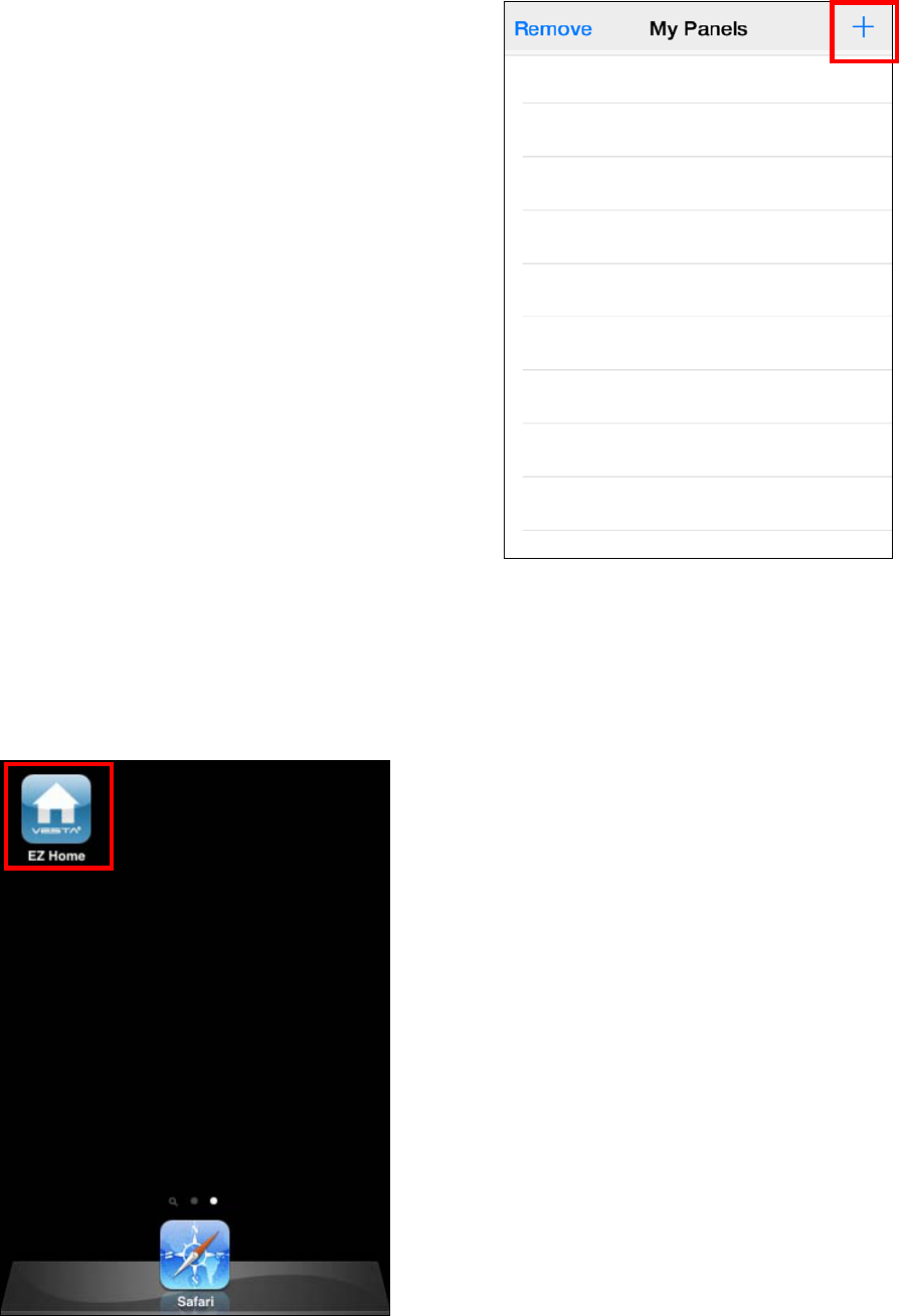
32
5. Vesta EZ Home
Application
The Vesta EZ Home Application is a
smartphone application designed to assist you
in sending SMS Command The intuitive and
simple interface help you communicate with
Control Panel by SMS message easily.
Vesta EZ Home supports basic system mode
control and setting configuration for end users.
For detailed full system setting programming,
please refer to 4.17. SMS Remote Command
for detail.
To use the application, go to iPhone App Store
or Android Google Play and search for “Vesta
EZ Home” to find the application. Download
and start the application.
5.1. For iPhone
The iPhone version of Vesta EZ Home
Application supports all SMS command
functions except SMS commands which inquire
Control Panel for information . This is due to
the limit of iOS system, which prohibits
incoming SMS message from accessing
application data.
An iOS version of 6.1 or higher is required to
use Vesta EZ Home on iPhone.
Select the Vesta EZ Home icon to start the
application.
Panel Selection
Upon starting the application, you will first enter
Panel Selection menu
For first time user, you need to first enter
your panel information, please select the
“+” icon.
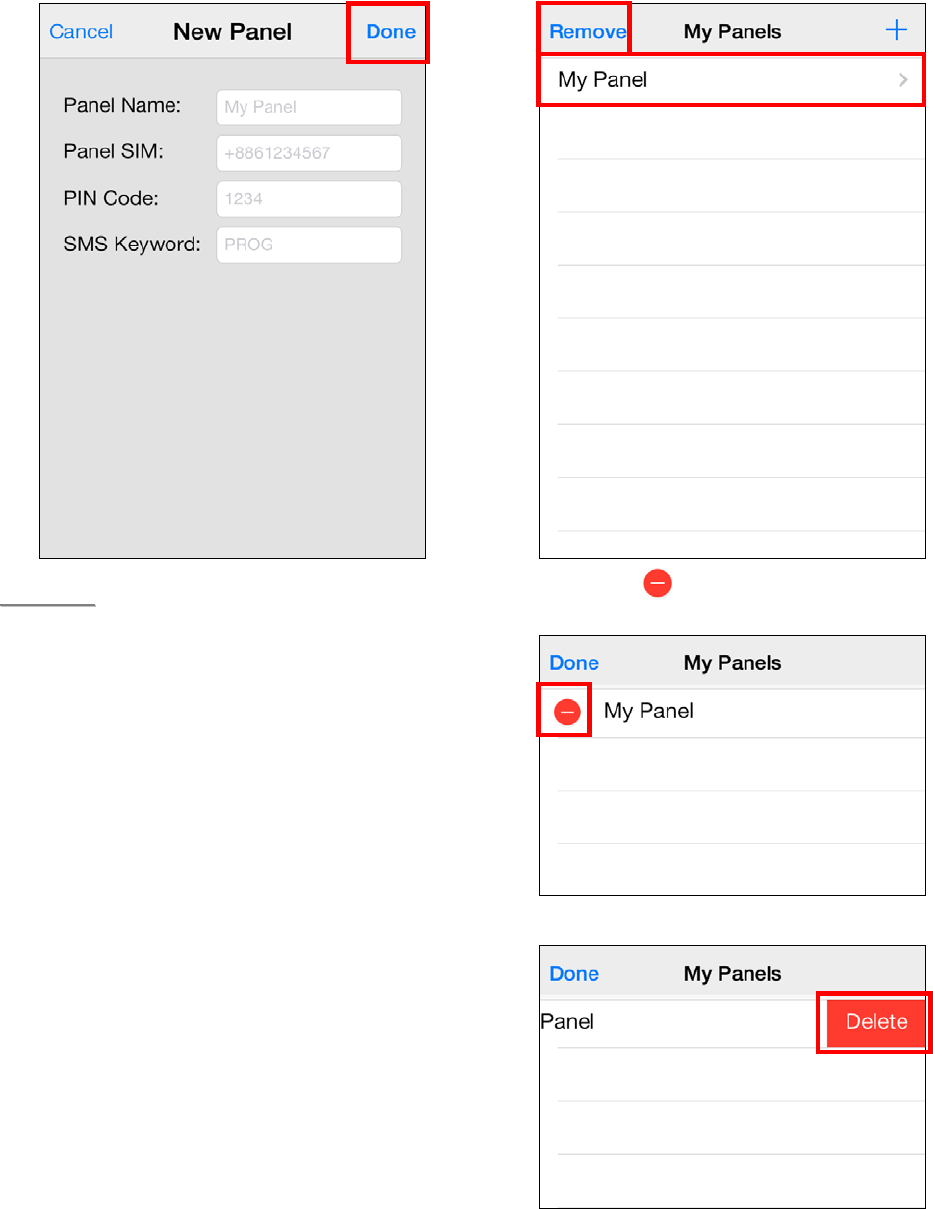
33
Enter the panel information, including the
panel name you want to use in the
application, panel SIM card number, a User
PIN Code and the SMS keyword used to
access the panel. Press “Done” to confirm
when finished.
<
<N
NO
OT
TE
E>
>
The PIN Code and SMS Keyword
entered in Panel Information are
included in every SMS command sent
with the app for the Control Panel to
verify the SMS command.
The PIN code must be identical to a
User PIN Code in the panel. The
factory default PIN code in the Control
panel is “1234” for User PIN Code 1.
You can change both SMS Keyword
and PIN code later by editing panel
information.
The panel does not have a default
SMS Keyword, you need to program a
Keyword in your panel first to use
Vesta EZ Home Application. Please
refer to 2.6. Panel Setting for
Keyword programming.
You will return to Panel Selection menu,
the new panel you entered will be
displayed, select the panel to proceed to
edit SMS commands for the panel. If you
want to remove the panel, press
“Remove.”
Press the icon, then “Delete” to
remove the panel from the application.
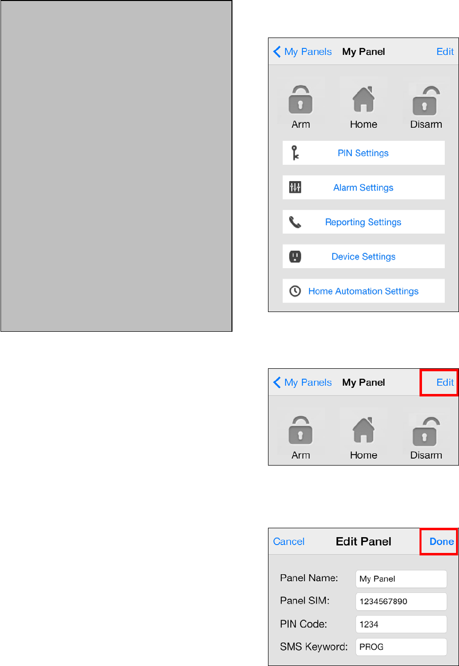
34
Panel Main Menu
The Panel Main Menu is displayed as follows:
Edit Panel Information
You can edit your control panel information by
pressing “Edit.”
Enter the new panel name, panel SIM card
number and PIN Code and the SMS keyword
you desired. Press “Done” to confirm when
finished.
<IMPORTANT NOTE>
The default setting in the application
may be different from the setting in
your Control Panel. When you use
the application to program the
system for the first time, please
check both application and Control
Panel settings for discrepancies.
If there are discrepencies, please
enter the correct setting in the
application, and press “Save” to
send the setting to Control Panel.
After you send an SMS command,
please make sure you receive
confirmation message from the
Control Panel before proceeding to
send the next command. If you
receive an error message from the
Control Panel, please resend the
SMS command again, or change
the setting back to previous setting
and save again. Otherwise the
setting saved in the application will
be different from the panel setting.
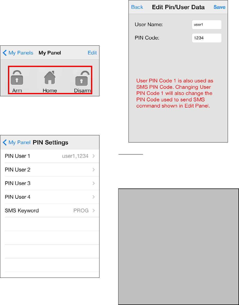
35
Away Arm / Home Arm / Disarm
To change system mode, select the icon for
Arm / Home / Disarm respectively. A SMS
message edit screen will appear for you to
confirm. Press “Send” to send the SMS
command to panel.
PIN Setting
The PIN Setting Menu allows you to edit User
PIN Codes and SMS Keyword.
Select the information you want to edit,
enter the information and press “Save”. A
SMS message edit screen will appear for
you to confirm. Press “Send” to send the
SMS command to panel.
<
<N
NO
OT
TE
E>
>
You can delete the User PIN code by
keeping the Pin Code field blank and
save the setting. User PIN Code 1
cannot be deleted.”
<IMPORTANT NOTE>
When you change SMS Keyword or
User PIN Code 1 and save the
setting, the SMS Keyword and PIN
Code stored in Panel Information
will also be updated accordingly.
Please make sure the Control Panel
successfully receives the SMS
command. If the panel fails to
receive the SMS command, you
need to edit the Panel Information
manually to change SMS Keyword
or PIN code back to previous
setting. Otherwise you will no longer
be able to control the panel with the
app.
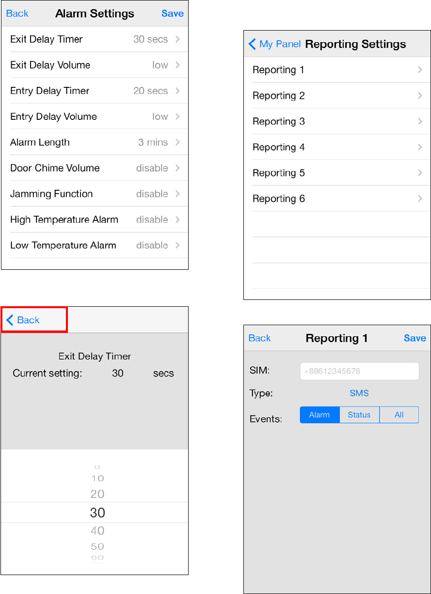
36
Alarm Setting
The Alarm Setting Menu allows you to edit
alarm related configuration.
Select the option you want to edit, you will
enter the edit screen
Slide the screen to select the value you
want to change, press “Back” to return to
menu when done.
When you are satisfied with all of your
alarm settings, press “Save”. A SMS
message edit screen will appear for you to
confirm. Press “Send” to send the SMS
command to panel.
Reporting Setting
The Report Setting Menu allows you to edit
your telephone numbers for reporting.
Select the reporting priority you want to edit.
Enter the telephone number for reporting,
and select report type and events. Only
SMS(CID)/ SMS(Text)/ GSM CID/ Voice
reporting options are available.

37
Press “Save”. A SMS message edit screen
will appear for you to confirm. Press
“Send” to send the SMS command to panel.
<
<N
NO
OT
TE
E>
>
You can delete the telephone number
by keeping the telephone number field
blank and save the setting.
Device Setting
The Device Setting Menu allows you to edit
device, control Siren, PSS, and request PIR
Camera images.
Edit Device
The Edit Device option allows you to edit a
device name, and attribute for Door
Contact, PIR and EIR Sensor.
Select the Zone number of the device you
want to edit and enter a new name,
For Door Contact, PIR Sensor, PIR
Camera and PIR Video Camera, please
select an attribute. (Only Burglar, Home
Omit and Entry attributes are available.)
For other devices without attribute, you can
select any attribute as it will not affect the
device setting.
Press “Save”. A SMS message edit screen
will appear for you to confirm. Press
“Send” to send the SMS command to panel.
You can also press “Delete This Device”
to remove the device in selected zone from
the Control Panel.
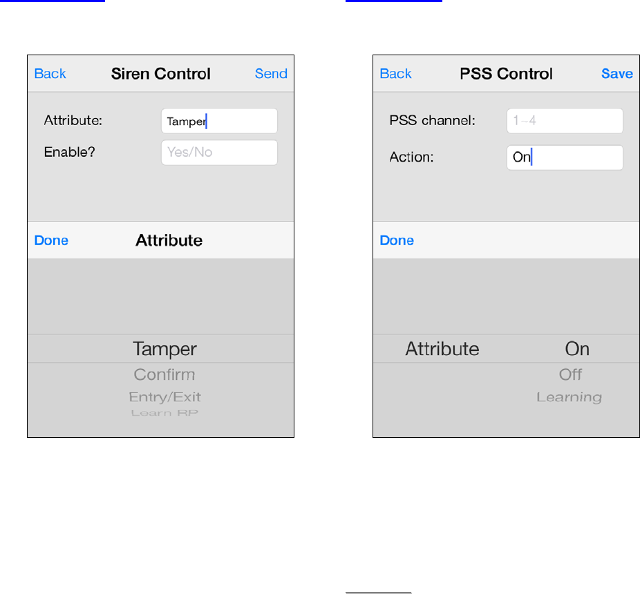
38
Siren Control
The Siren Control option allows you to
change Siren settings.
Select the function you want to edit and
choose to enable or disable the function.
Press “Save”. A SMS message edit screen
will appear for you to confirm. Press
“Send” to send the SMS command to panel.
PSS Control
The PSS Control option allows you to turn
on/off your Power Switch groups.
Select the Power Switch group you want to
control, then choose to turn on/off the
Power Switch.
Press “Save”. A SMS message edit screen
will appear for you to confirm. Press
“Send” to send the SMS command to panel.
<
<N
NO
OT
TE
E>
>
PSS learning is not available with
Vesta EZ Home.
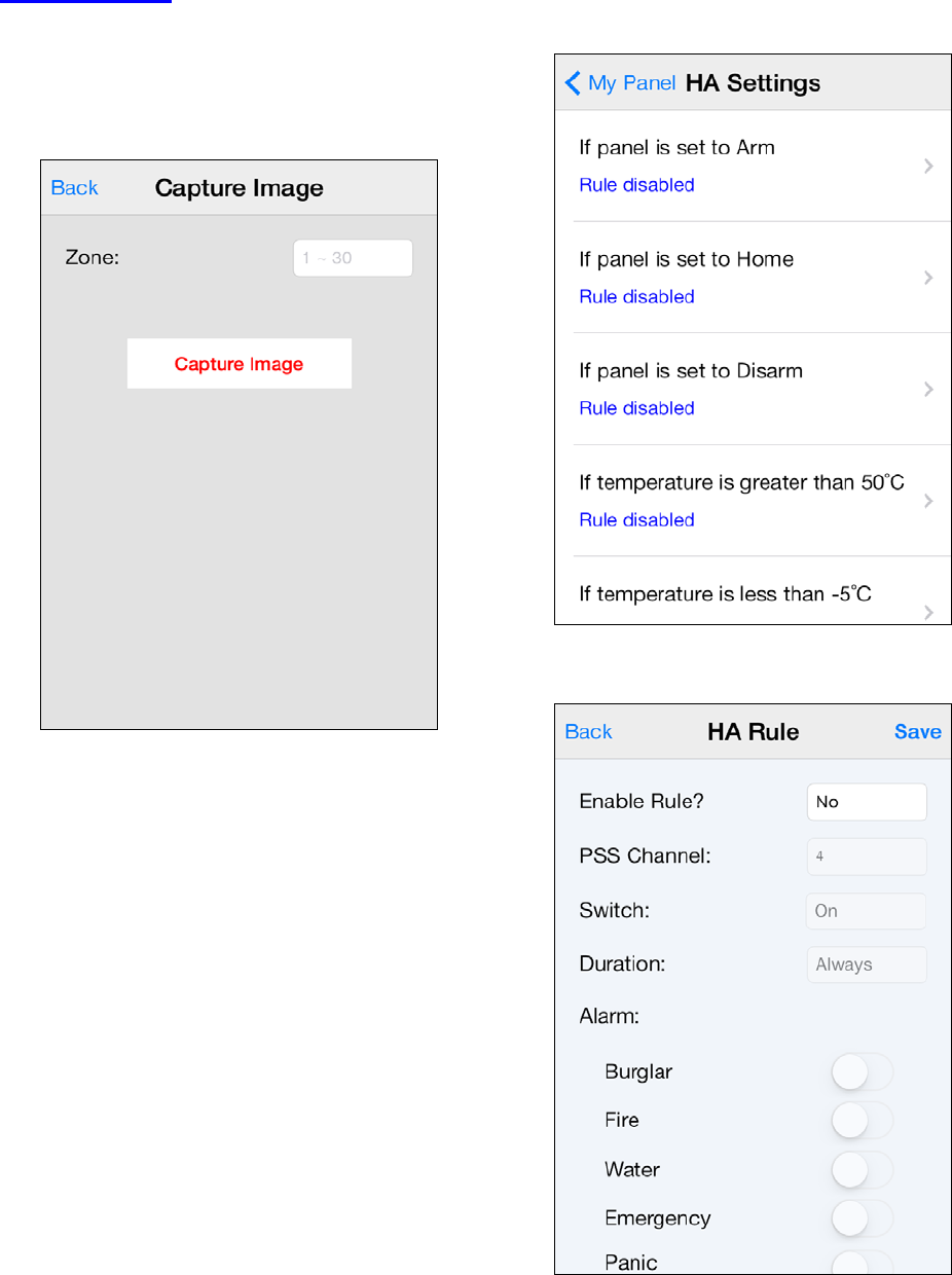
39
Capture Image
You can manually request your PIR
Camera, PIR Video Camera or IP Camera
to take a picture or video. The picture will
be sent to the destination programmed
under Media Upload section.
Specify the zone number of the PIR
Camera you want to take picture, then
press “Capture Image.” A SMS message
edit screen will appear for you to confirm.
Press “Send” to send the SMS command
to panel.
Home Automation Rules
Set Home Automation rules.
Select the condition, you will enter the rule
setting page for the condition.
Choose to enable/disable the rule, Power
Switch group on/off status and duration.
For High and Low temperature, you also
need to set the temperature value.
Press “Save”. A SMS message edit screen
will appear for you to confirm. Press
“Send” to send the SMS command to panel.
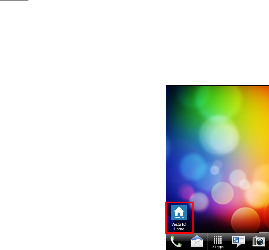
40
<
<N
NO
OT
TE
E>
>
For system mode change (Arm, Home,
Disarm), the Power Switch Ggroup
selection is limited to #1 only.
For High/Low Temperature and Time
setting. You can select any Power
Switch group from #1 ~ #4.
5.2. For Android Phone
The Android version of Vesta EZ Home
Application supports complete SMS command
functions, including the commands to inquire
Control Panel setting and update appllication
data with latest setting information.
An Adroid version of 2.2 or higher is required to
use Vesta EZ Home on your Andriod phone.
Select the Vesta EZ Home icon to start the
application.
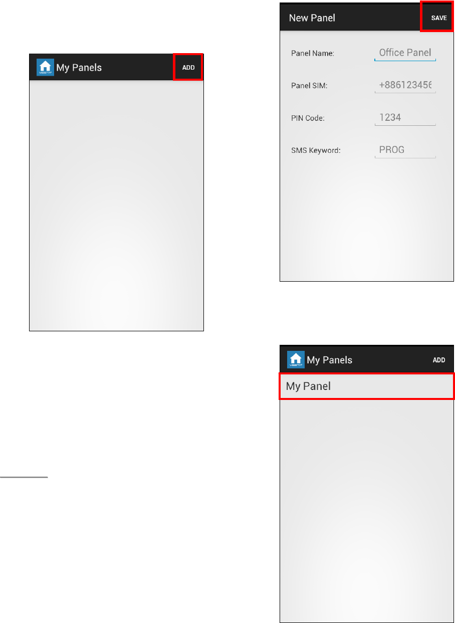
41
Panel Selection
Upon starting the application, you will first enter
Panel Selection menu
For first time user, you need to first enter
your panel information, please press
“ADD” button.
You will see the panel information,
including the panel name you want to use
in the application, panel SIM card number,
the PIN Code and SMS keyword used to
access the panel. Press “Save” to confirm
when finished.
<
<N
NO
OT
TE
E>
>
The PIN Code and SMS Keyword
entered in Panel Information are
included in every SMS command sent
with the app for the Control Panel to
verify the SMS command.
The PIN code must be identical to a
User PIN Code in the panel. The
factory default PIN code in the Control
panel is “1234” for User PIN Code 1.
You can change both SMS Keyword
and PIN code later by editing panel
information.
The panel does not have a default
SMS Keyword, you need to program a
Keyword in your panel first to use
Vesta EZ Home Application. Please
refer to 2.6. Panel Setting for
Keyword programming.
You will return to Panel Selection menu,
the new panel you entered will be
displayed, select the panel to proceed to
edit SMS commands for the panel.
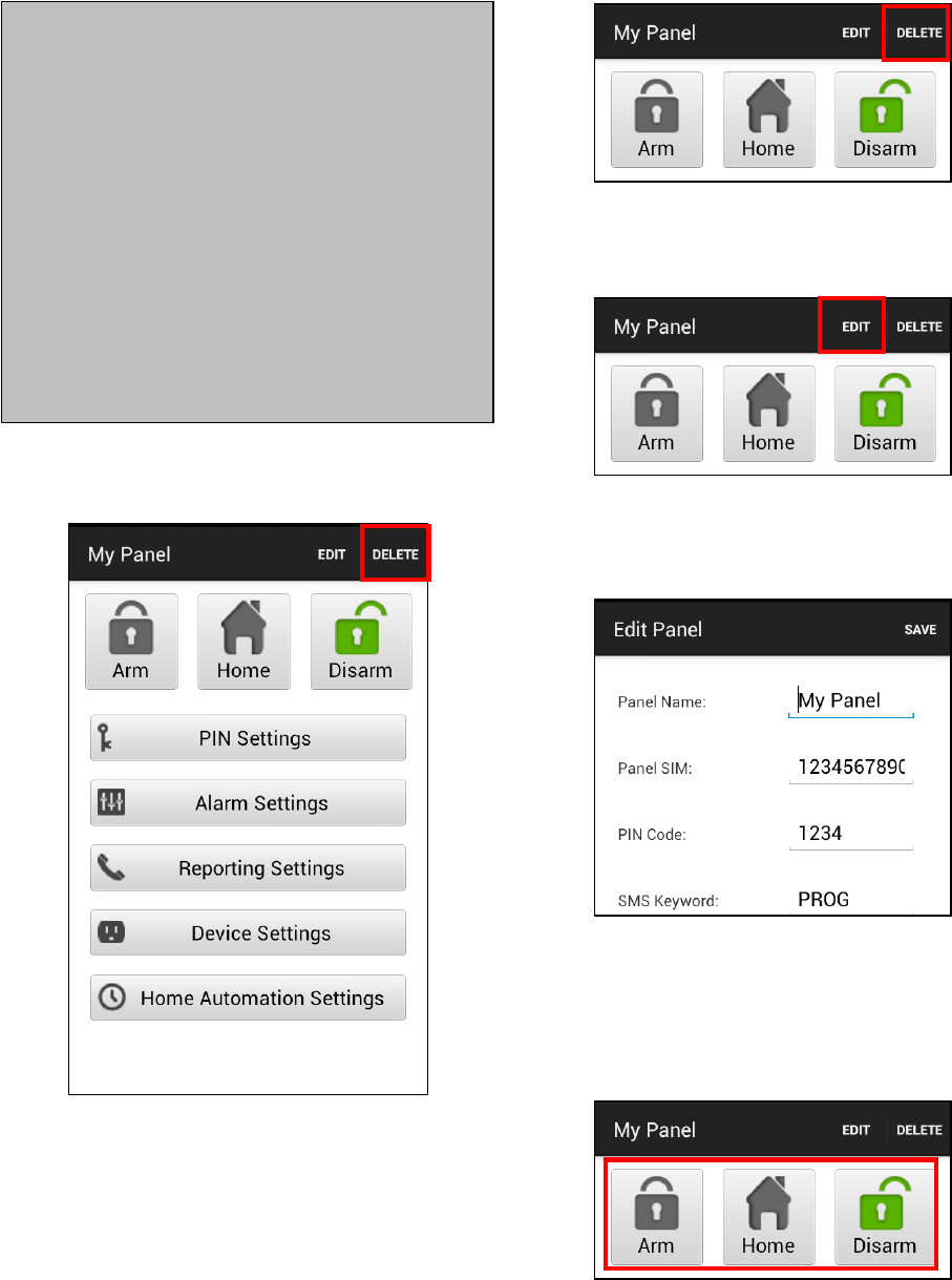
42
Panel Main Menu
The Panel Main Menu is displayed as follow:
You can select the different settings to further
program different functions. Pressing “Back”
button on your Android phone will return to
Panel Selection Menu.
Delete Panel
To remove current panel, select the
“Delete” button at the top right of Panel
Main Screen. You will be asked to confirm
the action, select “OK to delete the panel.”
You will return to Panel Selection Menu.
Edit Panel Information
You can edit the Control Panel information by
pressing “Edit”
Enter the new panel name, panel SIM card
number and PIN Code and the SMS keyword
you desired. Press “Save” to confirm when
finished.
Away Arm / Home Arm / Disarm
To change system mode, Press the Arm /
Home / Disarm button respectively. The phone
will send a SMS command to panel to execute
the command.
<IMPORTANT NOTE>
Whenever you send an SMS
command, please make sure you
receive confirmation message from
the Control Panel before
proceeding to send the next
command. If you receive an error
message from the Control Panel,
please resend the SMS command
again, or change the setting back to
previous setting and save again.
Otherwise the setting saved in the
application will be different from the
panel setting.
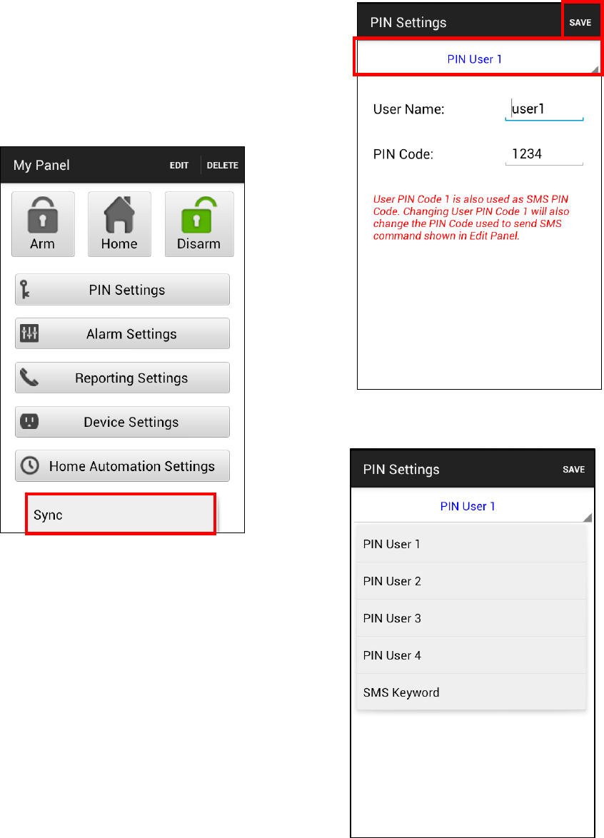
43
Sync with Panel
Press the Menu button on you Android phone
to bring up the “Sync” option. Press “Sync” to
send an SMS command to Control Panel
requesting it to report back its current mode.
Once your phone receives the SMS response
message from the Control Panel, Vesta EZ
Home app will update the current system mode
accordingly for you to view. Please remember
to sync your Vesta EZ Home app with all your
panel setting when you first create the panel.
PIN Setting
The PIN Setting Menu allows you to edit User
PIN Codes and SMS Keyword.
Select the top column to choose the setting
you want to edit
Select the information you want to edit,
enter the information and press “Save”.
The phone will send a SMS command to
panel.
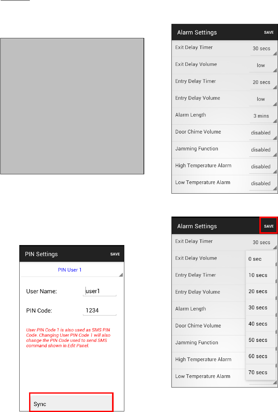
44
<
<N
NO
OT
TE
E>
>
You can delete the User PIN code by
keeping the Pin Code field blank and
save the setting. User PIN Code 1
cannot be deleted.”
Press the “Menu” button on your Android
phone to bring up the “Sync” function.
Press “Sync” to send a SMS command to
the Control Panel for inquiring current User
PIN code setting. Once your phone
receives the SMS response message from
the Control Panel, Vesta EZ Home app will
update the User PIN code information.
Alarm Setting
The Alarm Setting Menu allows you to edit
alarm related configuration.
Select the option you want to edit to
change the setting.
When you are satisfied with all of your
alarm settings, press “Save”. The phone
will send a SMS command to panel.
You can press the “Menu” button on your
Android phone to bring up the “Sync”
options and choose to sync either the
<IMPORTANT NOTE>
When you change SMS Keyword or
User PIN Code 1 and save the
setting, the SMS Keyword and PIN
Code stored in Panel Information
will also be updated accordingly.
Please make sure the Control Panel
successfully receives the SMS
command. If the panel fails to
receive the SMS command, you
need to edit the Panel Information
manually to change SMS Keyword
or PIN code back to previous
setting. Otherwise you will no longer
be able to control the panel with the
app.
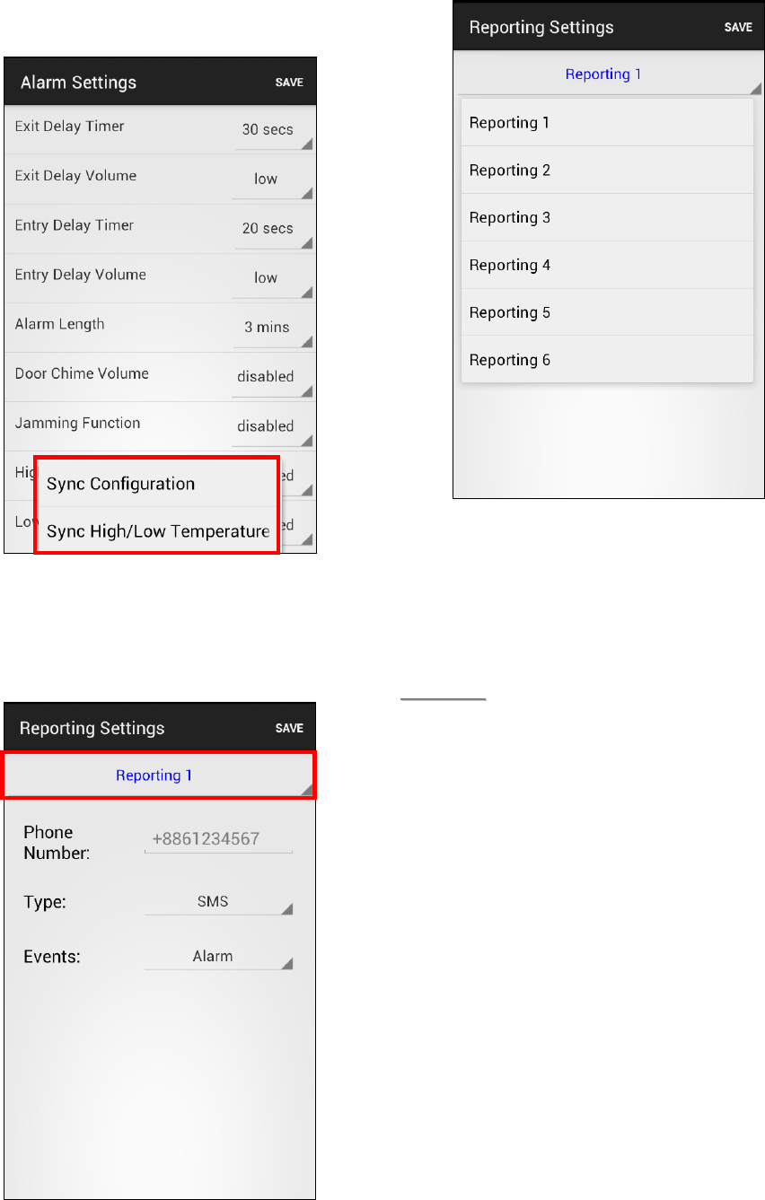
45
configurations or high/low temperature
setting.
Reporting Setting
The Report Setting Menu allows you to edit
your telephone numbers for reporting.
Select the top column to select the
reporting priority you want to edit.
Enter the telephone number for reporting,
and select report type and events. Only
SMS(CID)/ SMS(Text)/ GSM CID/ Voice
reporting options are available.
Press “Save”. The phone will send a SMS
message to panel.
<
<N
NO
OT
TE
E>
>
You can delete the telephone number
by keeping the telephone number field
blank and save the setting.
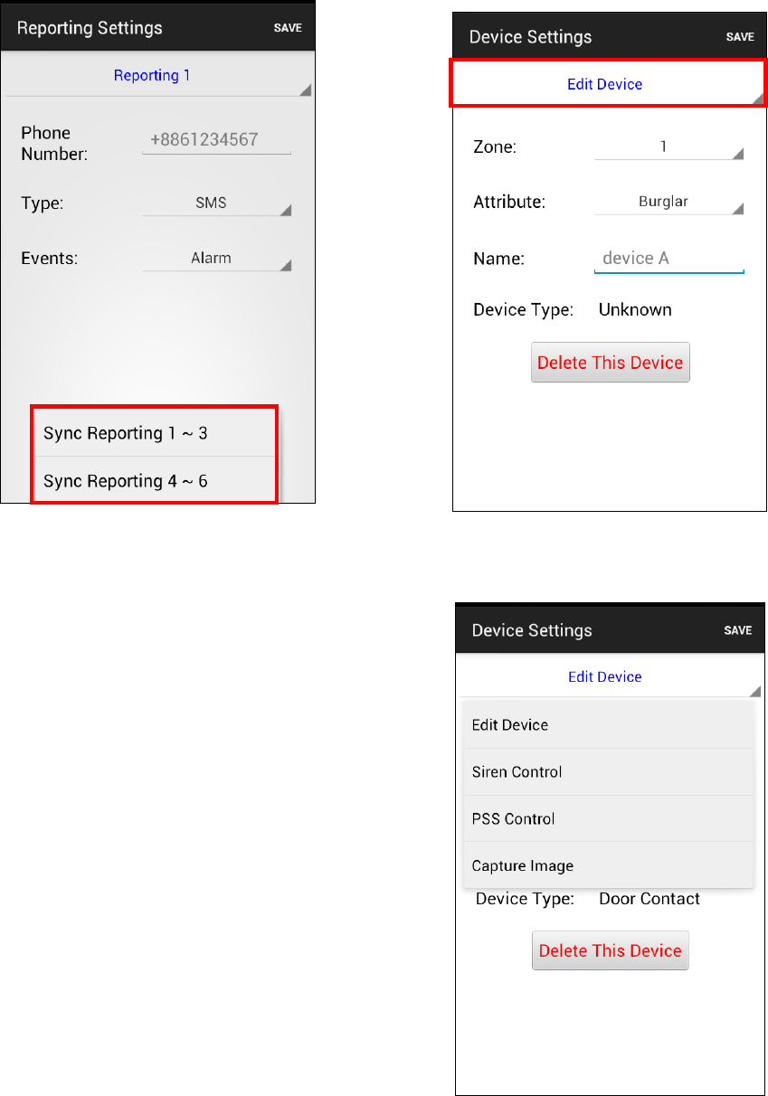
46
You can press the “Menu” button on your
Android phone to bring up the “Sync”
options and choose to sync either
Reporting 1~3 or 4~6.
Device Setting
The Device Setting Menu allows you to edit
device, control Siren, PSS, and request PIR
Camera image.
Select the top column to choose between
Edit Device, Siren, PSS Control, and PIR
Camera picture request
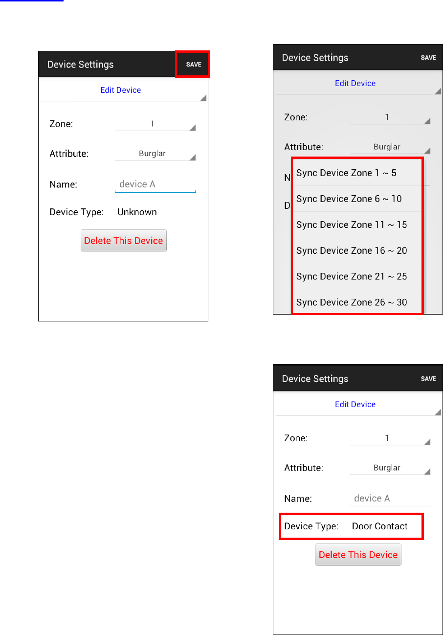
47
Edit Device
The Edit Device option allows you to edit a
device name, and attribute for Door
Contact, PIR and EIR Sensor.
Select the Zone number of the device you
want to edit and enter a new name,
For Door Contact, PIR Sensor, PIR
Camera and PIR Video Camera, please
select an attribute. (Only Burglar, Home
Omit and Entry attributes are available.)
For other devices without attribute, you can
select any attribute as it will not affect the
device setting.
Press “Save”. The phone will send a SMS
command to panel.
You can also press “Delete This Device ” to
remove the device from panel.
You can press the “Menu” button on your
Android phone to bring up the “Sync”
options and choose to sync device
information in different zones.
“Device Type” information will only be
updated after you successfully synced with
the Control Panel
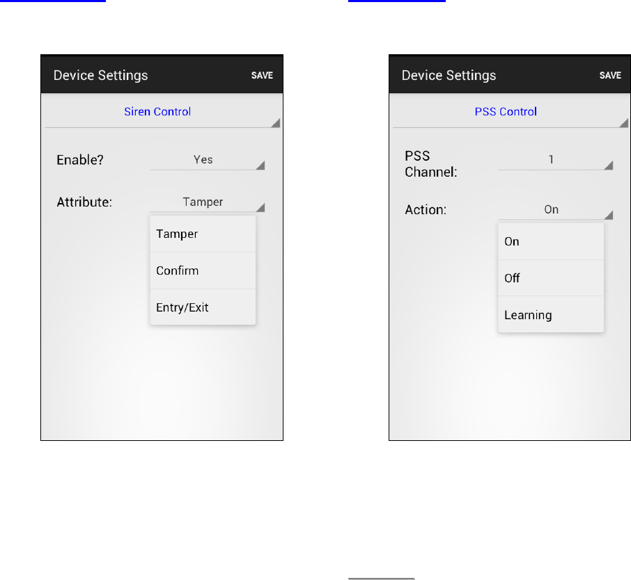
48
Siren Control
The Siren Control option allows you to
change Siren settings.
Select the attribute and choose to enable
or disable the function.
Press “Save”. The phone will send a SMS
command to panel.
.
PSS Control
The PSS Control option allows you to turn
on/off your Power Switch.
Select the Power Switch group you want to
control, then choose to turn on/off the
Power Switch.
Press “Save”. The phone will send a SMS
command to panel.
<
<N
NO
OT
TE
E>
>
PSS learning is not available with
Vesta EZ Home. Please ignore this
option.
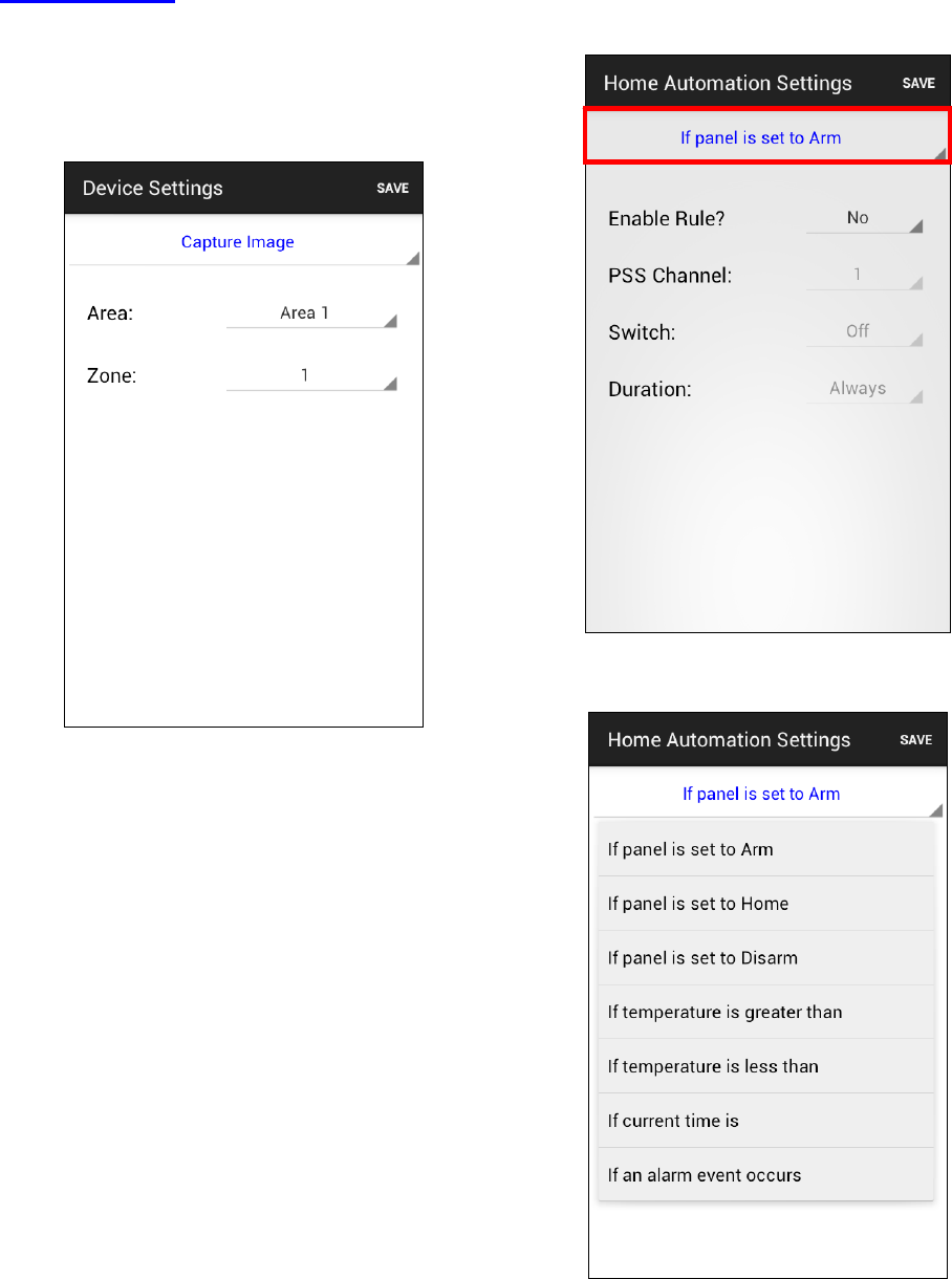
49
Capture Image
You can manually request your PIR
Camera, PIR Video Camera or IP Camera
to take a picture or video. The picture will
be sent to the destination programmed
under Media Upload section.
Select Area 1, then specify the zone
number of the PIR Camera you want to
take picture, then press “Save.” The phone
will send a SMS command to panel..
Home Automation Rules
Set Home Automation rules.
Select the top column to choose different
conditions.
Choose to enable/disable the rule, Power
Switch group on/off status and duration.
For High and Low temperature, you also
need to set the temperature value.

50
Press “Save”. A SMS message edit screen
will appear for you to confirm. The phone
will send a SMS command to panel.
<
<N
NO
OT
TE
E>
>
For system mode change (Arm, Home,
Disarm), the Power Switch group
selection is limited to #1 only.
For High/Low Temperature and Time
setting. You can select any Power
Switch group from #1 ~ #4.
6. Appendix
6.1. Event Code
100 – Medical
101 – Personal emergency
When the Wrist Transmitter /
Emergency Pendant (WTR) is pressed.
102 – Inactive
110 – Fire
111 – Smoke
When the Smoke Detector (SD) is
triggered.
114 – Heat
When the Heat Detector (HD) is
triggered.
120 – Panic
When the Panic Button of the Remote
Controller (RC) is pressed.
121 – Duress
When the Duress Code is entered to
disarm or arm the system.
122 – Silent Panic
When the panic button on a Remote
Controller (RC) set to silent panic is
pressed.
130 – Burglar
When any one of the following devices
is triggered:
The Door Contact (DC) set at
Burglar (@ B)
The Door Contact (DC) set at
Delay (@ D)
The PIR set at Burglar (@ B)
The PIR set at Delay (@ D)
131 – Burglar Perimeter
When a device set as Entry is
triggered in away arm mode.
132 – Burglar Interior
When a device set at Entry is
triggered in home arm mode.
133 – 24 Hours
When a device set as 24 Hour is
triggered.
51
137 – Panel Tamper
When the Control Panel tamper switch
is triggered.
139 – Verification / Alarm Confirmation
147 – Sensor Supervisor Failure
When the Control Panel fails to
receive the signal transmitted from any
one of the devices individually for a
preset period.
151 – Gas
154 – Water leakage
When a Water Sensor or Door Contact
set as Water is triggered.
158 – High Temperature
When the temperature exceeds High
Temperature setting.
159 – Low Temperature
When the temperature drops below
Low Temperature setting.
162 – CO detector
301 – AC Failure
When the AC power fails for more than
10 sec.
302 – Low Battery
When the battery voltage of the Panel
and any one of the devices is low.
311 – Panel Battery Missing/Dead
When the Control Panel Battery is
missing or disconnected.
344 – Interference
374 – Arm with Fault
When fault exists in system, and the
system is armed by confirming the arm
action. (Arm Fault Type set to Confirm.)
380 – Device AC Failure
When an AC power accessory device
loses the AC power connection.
383 – Device Tamper
When a device’s tamper switch is
triggered.
384 – Device Low Battery
When a device’s is under low battery.
389 – Self Test Failure
400 – Arm/Disarm (by Remote Controller)
When the system is armed or
disarmed by using the Remote
Controller.
401 – Arm/Disarm by Panel
When the system is armed or
disarmed by entering the PIN code.
408 – Set/Unset Disarm
407 – Disarm/Away Arm/Home Arm by
Remote Keypad
465 – Alarm Reset
570 – Zone Bypass
When fault exists in system, and the
system is armed by ignoring the fault
event. (Arm Fault Type set to Direct
Arm)
602 – Periodic test report
When Control Panel makes periodic
Check-in reporting.
606 - Follow-On Function
When Control Panel reports to CMS to
request opening Listen-in function.
52
Federal Communication Commission Interference Statement
This equipment has been tested and found to comply with the limits for a Class B digital device, pursuant to
Part 15, 22 & 24 of the FCC Rules. These limits are designed to provide reasonable protection against
harmful interference in a residential installation.
This equipment generates, uses and can radiate radio frequency energy and, if not installed and used in
accordance with the instructions, may cause harmful interference to radio communications. However, there
is no guarantee that interference will not occur in a particular installation. If this equipment does cause
harmful interference to radio or television reception, which can be determined by turning the equipment off
and on, the user is encouraged to try to correct the interference by one of the following measures:
. Reorient or relocate the receiving antenna.
. Increase the separation between the equipment and receiver.
. Connect the equipment into an outlet on a circuit different from that to which the receiver is connected.
. Consult the dealer or an experienced radio/TV technician for help.
FCC Caution: To assure continued compliance, any changes or modifications not expressly approved by the
party responsible for compliance could void the user's authority to operate this equipment. (Example - use
only shielded interface cables when connecting to computer or peripheral devices).
FCC Radiation Exposure Statement
This equipment complies with FCC RF radiation exposure limits set forth for an uncontrolled environment.
This equipment should be installed and operated with a minimum distance of 20 centimeters between the
radiator and your body.
This transmitter must not be co-located or operating in conjunction with any other antenna or transmitter.
The antennas used for this transmitter must be installed to provide a separation distance of at least 20 cm
from all persons and must not be co-located or operating in conjunction with any other antenna or transmitter.
This device complies with Part 15, 22 & 24 of the FCC Rules. Operation is subject to the
following two conditions:
(1) This device may not cause harmful interference, and
(2) This device must accept any interference received, including interference that may cause
undesired operation.