Climax Technology Co 616PU Patient Box User Manual users manual
Climax Technology Co Ltd Patient Box users manual
users manual
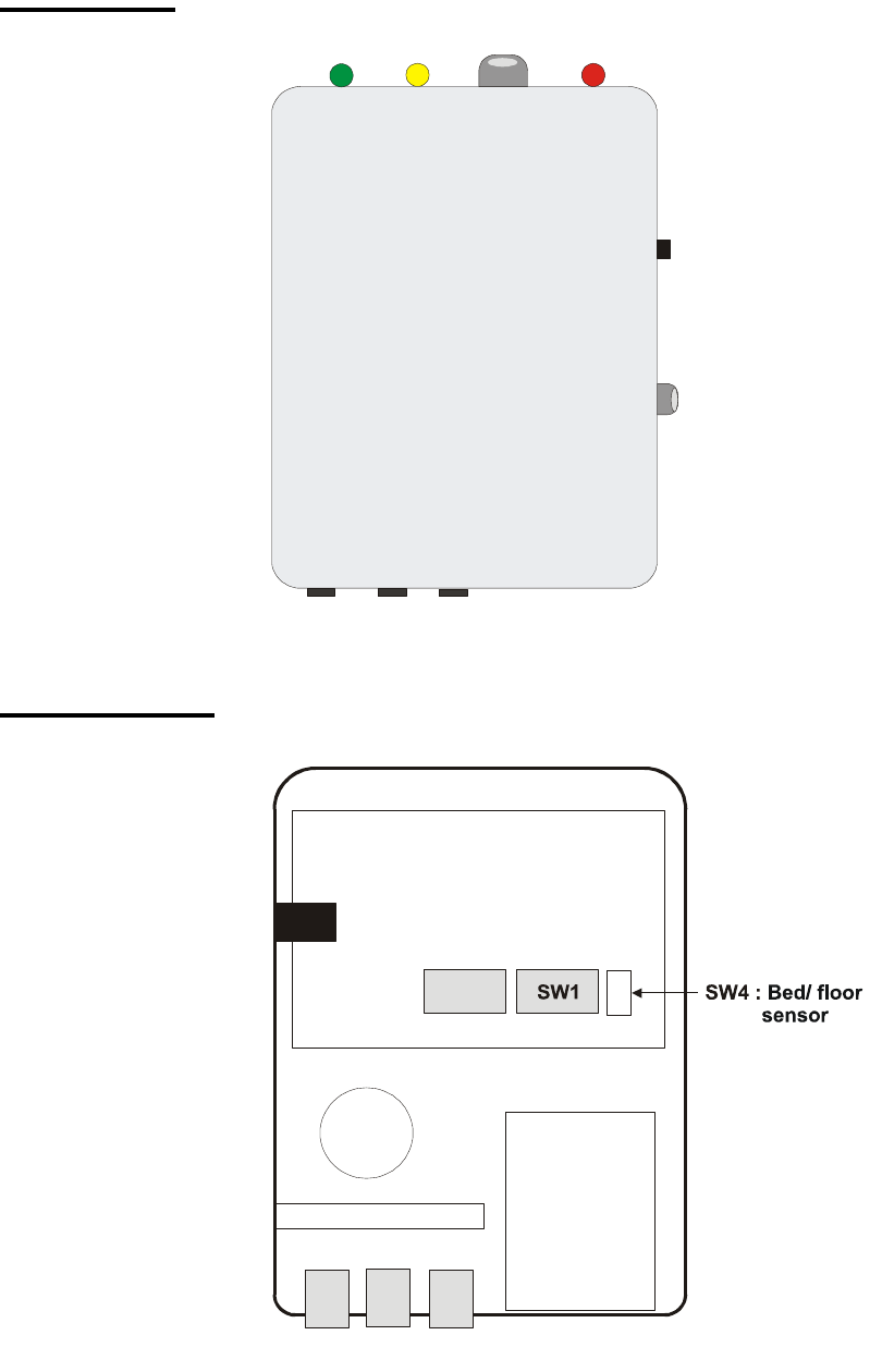
#2130 – PATIENT BOX
I
ID
DE
EN
NT
TI
IF
FY
Y
T
TH
HE
E
P
PA
AR
RT
TS
S:
:
Front view
Internal view
Battery
Buzzer
SW2
Power
LED HOLD HOLD/
RESET
Low
battery
POWER
ON/OFF
Nurse call
jack
Bed/
floor
sensor
Power
Jack Bed/
floor
sensor
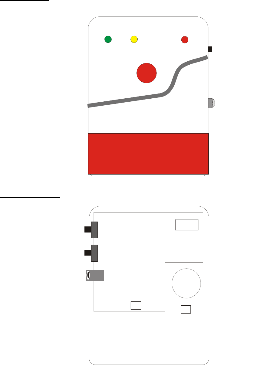
#2131 – BELL BOX
I
ID
DE
EN
NT
TI
IF
FY
Y
T
TH
HE
E
P
PA
AR
RT
TS
S:
:
Front view
Internal view
Power SW
Sound SW
DC Jack
CON1
Battery
ID SW
Buzzer
LED
Gree
LED Orange
LED Red LED
POWER SW
SOUND SW
BUTTON

I
IN
NT
TE
ER
RN
NA
AL
L
S
SW
WI
IT
TC
CH
HE
ES
S:
:
SW 1 : ID Code Switch
SW 2 : Programming Switch
Set Volume: SW2-1 & SW2-2
Set Hold Time: SW2-3 & SW2-4
Set Delay Time: SW2-5 & SW2-6
Set Alarm Length: SW2-7 & SW2-8
SW3 : Power ON/OFF switch
SW4 : Sensor Type switch
C
CO
ON
NN
NE
EC
CT
TO
OR
RS
S:
:
CON1 : Battery connector
CON2 : Buzzer connector
CON3 : External DC input (9V)
J
JU
UM
MP
PE
ER
RS
S:
:
JP3 & JP4 : Sensor input
N
NO
OT
TE
E:
:
Both BED sensor and FLOOR sensor are currently available.
BEAM sensor will be available with next model.
When BED sensor is intended for use, the other jumper is not available for any additional
sensor.
P
PR
RO
OG
GR
RA
AM
MM
MI
IN
NG
G
#
#2
21
13
30
0:
:
Step 1. Remove the cover and locate the SW2, the Programming Switches on the PCB..
Step 2. Slide SW2-1 and SW2-2 up or down for your desired Volume
SILENT LOW MIDDLE HIGH
SW2-1 DOWN UP DOWN UP
SW2-2 DOWN DOWN UP UP
Step 3. Slide SW2-3 and SW2-4 up or down for your desired Hold Length when the Hold Button is
pressed. Choices available are: 5, 15, 30 or 60 seconds:
5 sec 15 sec 30 sec 60 sec
SW2-3 DOWN UP DOWN UP
SW2-4 DOWN DOWN UP UP

Step 4. Slide SW2-5 and SW2-6 up or down for your desired Alarm Activation Delay Time.
Choices available are: 0, 2 or 4 seconds:
0 sec 2 sec 2 sec 4 sec
SW2-5 DOWN UP DOWN UP
SW2-6 DOWN DOWN UP UP
Step 5. Slide SW2-7 and SW2-8 up or down for your desired Alarm Length. Choices available are
15, 30, 60 seconds or continuous without automatic reset:
15 sec 30 sec 60 sec Continuous
SW2-7 DOWN UP DOWN UP
SW2-8 DOWN DOWN UP UP
Step 6. Locate SW4, the Sensor Type Switch and slide SW4-1 and SW4-2 up or down for the
appropriate sensor that is intended for use with the Patient Box.
SW4-1 SW4-2
BED DOWN DOWN
FLOOR UP DOWN
BEAM UP UP
I
IN
NS
ST
TA
AL
LL
LI
IN
NG
G
#
#2
21
13
30
0
The Patient Box can be mounted as noted in drawings 616D, 616E, and 616F. Unit can also
be mounted using adhesive backed hook and loop closure.
Find the location where #2130 is to be mounted.
Using the large screws provided, mount on wall through
the 4 x base plate mounting holes.
Fix the siren cover with the securing screw.
The installation is now completed.
T
TH
HE
E
P
PO
OW
WE
ER
R
S
SU
UP
PP
PL
LY
Y:
:
An AC power adaptor is required to connect to a wall out for power source. Be sure only to
use an adaptor with the appropriate DC voltage rating to prevent component damage. A DC
9V, 500mA adaptor is generally used to power the unit.
Rechargeable Battery
In addition to the adaptor, there is a rechargeable battery inside the unit that serves as a back
up in case of a power failure.
The battery used is a 3-pack of AAA Alkaline batteries.
During normal operation, the AC power adaptor is used to supply power to the unit and
at the same time recharge the battery.
When the battery is fully charged, it can provide back-up power for a period of at least 8
hours. It takes approximately 48 hours to fully charge the battery
G
GE
ET
TT
TI
IN
NG
G
S
ST
TA
AR
RT
TE
ED
D:
:
With a BED system:
Step 1. Find a suitable location for the Patient Box to be installed.
Step 2. Apply the AC Power.
Step 3. Press and hold the Power Button for 2 full seconds. The Green LED will light and begin to
flash.
Step 4. Choose between JP3 and JP4 and plug the Sensor unit into the Patient Box.
For a BED Sensor:
Step 5a. Apply weight to the sensor pad to hear the activation beep.
The system is now activated.
For a FLOOR sensor:
Step 5b. #2130 will give a 5-second period for the nurse to leave the room without triggering the
FLOOR sensor. Afterwards, the unit will sound a beep to indicate its activation.
The system is now activated.
O
OP
PE
ER
RA
AT
TI
IO
ON
N:
:
With a BED system:
When the patient lifts weight off of sensor pad,
Response at Patient Unit, #2130:
After the Delay Time has expired, the #2130 sounds its alarm warning beep and
sends out a signal to the #2131
After 5 seconds, #2130 will notify the Nurse Station via its nurse call jack and
the signal will repeat every 2 seconds.
Response at Bell Box Unit, #2131:
Once the signal is received from the #2130, #2131 fast flashes all LEDs and
cycle an alarm tone.
Reset the system:
If the patient returns to the sensor pad and applies weight before the Delay Time
expired:
#2130 stops sounding and transmit alarm signal to #2131
No Nurse call will be placed.
#2131 stops sounding and flashing and reset automatically after 5 minutes
After the Delay Time expired and the nurse responds:
Press the large button on the #2131 to stop sounding and lower the flashing
rate of the LEDs
#2131 will reset automatically after 5 minutes.
Place the patient back in BED and return the pressure on the sensor pad.
#2130 will then reset itself automatically.
To lift weight off of sensor pad, and not activate the #2130,
Press the “HOLD” button on #2130 for one full second.
#2130 sounds one beep to confirm the “HOLD” command and will hold the system
for the Hold Length specified at programming step.
Green LED stops flashing and Orange LED begins flashing
You may press the Power Switch once to cancel the “HOLD” command at anytime
before the Hold Length is expired, or #2130 will sound another beep when the Hold
Length is up to warn the user.
Orange LED stops flashing and Green LED starts to flash
During the Hold Length period, #2130 ignores all signals received from the sensor
After the Hold Length period expired before the patient leaves the bed, in despite,
#2130 sounds one beep to indicate it is back in Monitoring Mode.
To extend the Hold Length:
Press the “HOLD” button once to extend the Hold Length for a time period as
specified at pre-set.
With a FLOOR system:
When the patient leaves the bed and steps on the sensor pad,
Response at Patient Unit, #2130:
Immediately, the #2130 sounds its alarm warning beep and sends out a signal
to the #2131
After 5 seconds, #2130 will notify the Nurse Station via its nurse call jack and
the signal will repeat every 2 seconds.
Response at Bell Box Unit, #2131:
Once the signal is received from the #2130, #2131 fast flashes all LEDs and
cycle an alarm tone.
Reset the system:
The nurse responds before the Alarm Length expires:
Press the large button on the #2131 to stop sounding and lower the flashing
rate of the LEDs
Place the patient back in BED and #2130 will then reset itself automatically.
Press the large button on the #2131 again to reset the system, or the system
will reset automatically after 5 minutes.
The nurse responds after the Alarm Length expired:
Place the patient back in BED and #2130 will then reset itself automatically.
Press the large button on the #2131 to reset the system before leaving the
room.
If not, when it is at this semi-reset stage, #2131 will ignore all alarm signals
sent from the #2130
If not, #2131 will reset automatically after 5 minutes.
To move the patient around and not activate the #2130,
Press the “HOLD” button on #2130 for one full second.
#2130 sounds one beep to confirm the “HOLD” command and will hold the system
for the Hold Length specified at programming step.
Green LED stops flashing and Orange LED begins flashing
You may press the Power Switch once to cancel the “HOLD” command at anytime
before the Hold Length is expired, or #2130 will sound another beep when the Hold
Length is up to warn the user.
Orange LED stops flashing and Green LED starts to flash
During the Hold Length period, #2130 ignores all signals received from the sensor
After the Hold Length period expired, #2130 sounds one beep to indicate it is back in
Monitoring Mode.
To extend the Hold Length:
Press the “HOLD” button once to extend the Hold Length for a time period as
specified at pre-set.
N
NO
OT
TE
E:
:
This equipment has been tested and found to comply with the limits for a Class B digital
device, pursuant to Part 15 of the FCC Rules. These limits are designed to provide
reasonable protection. This equipment generates, uses and can radiated radio frequency
energy and, if not installed and used in accordance with the instructions, may cause harmful
interference to radio communications. However, there is no guarantee that interference will
not occur in a particular installation If this equipment does cause harmful interference to
radio or television reception, which can be determined by turning the equipment off and on,
the user is encouraged to try to correct the interference by one or more of the following
measures:
Reorient or relocate the receiving antenna.
Increase the separation between the equipment and receiver.
Connect the equipment into an outlet on a circuit different from that to which the
receiver is connected.
Consult the dealer or an experienced radio/TV technician for help.
Changes or modifications not expressly approved by the party responsible for compliance
could void the user‘s authority to operate the equipment.