Climax Technology Co 862 PIR Motion Sensor Camera User Manual
Climax Technology Co Ltd PIR Motion Sensor Camera Users Manual
Users Manual
1
PIR Motion Sensor Camera
VST-862P-F1
Introduction
VST-862P-F1 is a passive infrared (PIR) motion sensor camera. It is capable of sending wireless signals and captured
images (picture quality of up to 640 x 480 pixels) to the Control Panel upon movement detection.
The PIR Camera is designed to give a typical detection range of 12 meters when mounted at 2 meters above ground. It
has a pet-immune range of 7 meters and will not trigger false alarm from your household pets within this distance.
The PIR Camera consists of a two-part design made up of a cover and a base. The cover contains all the electronics and
optics and the base provides a means of fixing. The base has knockouts to allow mounting on either a flat surface or in a
corner situation with a triangular bracket for corner mounting.
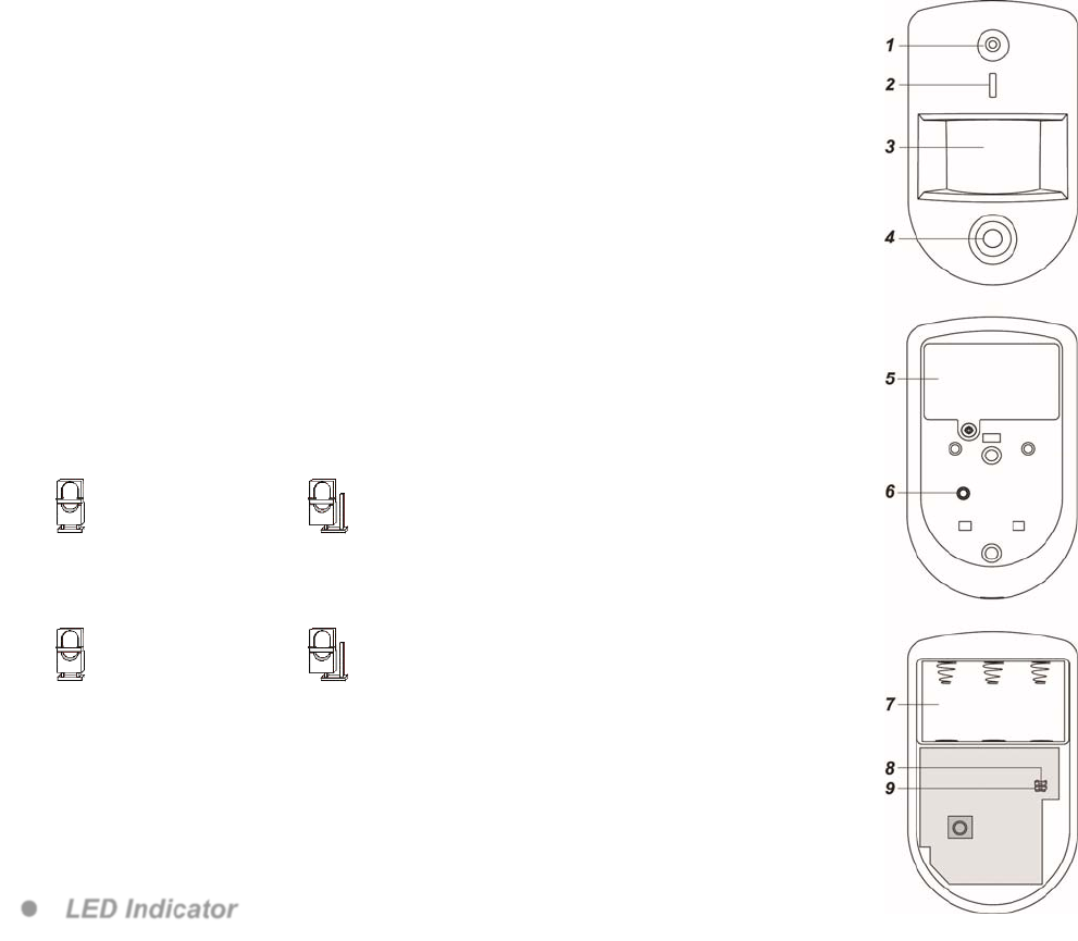
Parts Identification
1. Flash LED
The Flash LED delivers sufficient light for image capture under low lighting
condition.
2. Blue LED/Function Button
Blue LED:
(Please refer to LED Indicator description below for details)
Function Button Usage:
- Press and hold the button for 3 seconds to send a learn code, release when Blue
LED light on.
- Press the button once to enter test mode for 3 minutes.
3. IR Sensor
4. PIR Camera Lens
5. Battery Compartment Cover
6. Tamper Switch
7. Battery Compartment
8. Sensitivity Adjustment Jumper Switch (JP3)
- Jumper On: the PIR’s sensitivity level is set to High.
- Jumper Off: the PIR’s sensitivity level is set to Normal. (Factory Default)
9. Sleep Timer Jumper Switch (JP2)
- Jumper On: After movement detection, the PIR Camera does not enter sleep mode and
will transmit detection signal again immediately if triggered (Factory Default).
- Jumper Off: PIR Camera has a “sleep time” of approximately 1 minute after motion
detection to conserve power.
Features
LED Indicator
In Normal operation mode, the Blue LED will not light except in the following situations:
When the PIR Camera is in low battery condition, every time it transmits a detected movement, the Blue LED will
flash for 2 seconds.
When the cover is opened and the tamper switch is violated, the Blue LED will flash for 2 seconds, to indicate it is
transmitting “Tamper” signal.
When the Tamper condition persists, every time it transmits a detected movement, the Blue LED will flash for 2
seconds.
When PIR Camera enters Test Mode, the Blue LED will flash for 1 second. During Test mode, the Blue LED will
Jumper On
The jumper link is inserted
connecting the two pins.
Jumper Of
f
if the jumper link is removed
or “parked” on one pin.
Jumper On
The jumper link is inserted
connecting the two pins.
Jumper Of
f
if the jumper link is removed
or “parked” on one pin.
2
also flash for 2 seconds every time a movement is detected.
When the PIR Camera is in 30 seconds warm up period, the Blue LED will slow flash.
When the PIR Camera is transmitting captured images under fault conditions (low battery, tamper switch
activated), the Blue LED will continuous flash.
Image Capture
When the alarm system is armed, the PIR Camera will capture 1, 3 or 6 alarm images in 640 x 480 or 320 x 240
resolutions (programmable from Control Panel) upon movement detection. You can also manually request the PIR
Camera to take a picture through the Control Panel. The captured images will be transferred to the Control Panel for
users view.
Warm Up Period
When the Control Panel system enters arm mode, or when PIR Camera is put into Test Mode, the PIR Camera will
warm up for 30 seconds. Do not trigger the PIR Camera during the 30-second warm up period. The Blue LED will
slow flash during the warm up period only when PIR enters for Test Mode.
Sleep Timer
When Jumper Switch 2 is set to Off, the PIR Camera has a “sleep time” of approximately 1 minute to conserve
power. After transmitting for a detected movement, the PIR Camera will not retransmit for 1 minute. Any detected
movement during this period will reset the sleep time to 1 minute. Continuous movement in front of the PIR Camera
will therefore not exhaust the battery.
Battery and Low Battery Detection
The PIR Camera uses three CR123A 3V Lithium batteries as its power source. Remove the Battery Compartment
Cover and insert the batteries to activate the PIR Camera.
The PIR Camera features Low Battery Detection function. When the battery voltage is low, the PIR Camera will
transmit Low Battery signal to the Control Panel. If movement is detected under Low Battery condition, the Blue
LED will flash for 2 seconds.
When changing battery, after removing the old battery, press the Tamper Switch or the Function Button twice to fully
discharge before inserting new batteries
Tamper Protection
The PIR Camera is protected by a tamper switch which is compressed when the PIR Camera is properly installed.
When the PIR Camera is removed from mounted surface or its cover opened, the tamper switch will be activated and
the PIR Camera will send a tamper open signal to the system control panel to remind the user of the condition. If
movement is detected when the tamper switch is open, the Blue LED will flash for 2 seconds.
Supervision
The PIR Camera will conduct a Self-test Periodically by transmitting a supervisory signal once every 30 to 50
minutes.
Test Mode
Test mode is for you to check the PIR camera’s detection range (not shooting coverage).
Press the Function button once to enter Test mode for 3 minutes, the Blue LED will flash for 1 second.
The PIR camera will warm up for 30 seconds. Please do not trigger the Camera during this warming-up period.
After the warm-up period, you can trigger PIR camera to check IR detection range. If PIR camera is triggered, the
Blue LED will flash for 2 seconds.
<NOTE>
For Test Mode to run smoothly, It is recommended to disable sleep timer.
Getting Started
Remove the Battery Compartment Cover by loosening the Battery Compartment Screw.
Insert the batteries. Orient the battery according to the polarity indication.
Put the Control Panel into learning mode, refer to Control Panel manual for details.
Press and hold the function for 3 seconds, release the button when the Blue LED light on, the Blue LED will light
on for 25 seconds in learning mode, add PIR Camera into the Control Panel during this period (refer to your
Control Panel to finish learn in process). If the PIR is successfully added into the Control Panel, the Blue LED will
flash 6 times to indicate. If PIR is not added within 25 seconds, please repeat learning process.
After the PIR Camera is learnt-in, put the Control Panel into “Walk Test” mode, hold the PIR Camera in the
desired location, and press the Function Button to confirm this location is within signal range of the Control Panel,
refer to Control Panel manual to complete Walk Test.
When you are satisfied that the PIR Camera work in the chosen location, you can proceed to mounting.
3
Installation
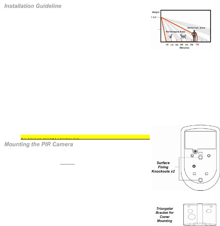
Installation Guideline
The PIR Camera is designed to be mounted on either a flat surface or in
a corner situation with fixing screws and plugs provided.
The base has knockouts, where the plastic is thinner, for mounting
purpose. Two knockouts are for surface fixing and a triangular mounting
bracket is used for corner fixing.
It is recommended to install the PIR Camera in the following
locations
Mount where the animals cannot come to the detection area by
climbing on furniture or other objects.
Don’t aim the detector at stairways the animals can climb on.
In a position such that an intruder would normally move across the PIR’s field of view.
Between 1.9 and 2m above ground for best performance. When mounted at 1.9 meters above ground, it
gives a typical PET IMMUNE range of 7 meters. As the PIR Pet-Immune Camera is higher from above
ground, it gives a farther PET IMMUNE range.
In a corner to give the widest view.
Where its field of view will not be obstructed e.g. by curtains, ornaments etc.
For a small 3 to 5m room, install between 1.9 to 2m above ground.
Limitations
Do not install the PIR Camera completely exposed to direct sunlight.
Avoid installing the PIR Camera in areas where devices may cause rapid change of temperature in the
detection area, i.e. air conditioner, heaters, etc.
Avoid large obstacles in the detection area.
Not pointing directly at sources of heat e.g. Fires or boilers, and not above radiators.
Avoid moving objects in the detection area i.e. curtain, wall hanging etc.
Be sure to always remain the RSSI signal strength steady at “4”.
Mounting the PIR Camera
Surface mounting:
1. Open the cover by loosening the Cover Screw using a Philips screwdriver.
2. Break through the 2 Surface knockouts at the center of base.
3. Use the holes as template to drill holes on the surface.
4. Insert the wall plugs if fixing it into plaster or brick.
5. Screw the base into the wall plugs.
6. Fit the cover onto the base and tighten.
Corner mounting:
1. Break through the two knockouts on the triangular bracket.
2. Use the two holes as template to drill holes on the corner surface.
3. Insert the wall plugs.
4. Screw the triangular bracket into the wall plugs with the two pointing
sticks on top facing you.
5. Fit the PIR Camera onto the hooks of the triangular bracket.
This device complies with Part 15 of the FCC Rules. Operation is subject to the following two
conditions:
(1) This device may not cause harmful interference, and (2) This device must accept any
interference received, including interference that may cause undesired operation.