Climax Technology Co BTX BTX Ankle Tether User Manual revised
Climax Technology Co Ltd BTX Ankle Tether Users Manual revised
Users Manual revised

U
SER
M
ANUAL
BTX Ankle Tether

USER MANUAL
BTX Ankle Tether
TABLE OF CONTENTS
1.0 Product Overview ............................................................................................................... 3
1.1 Primary Functionality of the BTX Ankle Tether............................................................... 3
2.0 Operational Description..................................................................................................... 3
2.1 Off State............................................................................................................................. 4
2.2 On State ............................................................................................................................. 4
2.3 Check Battery Voltage....................................................................................................... 5
2.4 Check Conductive Link ..................................................................................................... 5
2.5 Check Optical Link............................................................................................................ 5
3.0 Installation Instructions ..................................................................................................... 6
3.1 BTX Ankle Tether ............................................................................................................. 6
3.2 Tracking/Reporting Unit - TRU ........................................................................................ 6
2
USER MANUAL
BTX Ankle Tether
1.0 PRODUCT OVERVIEW
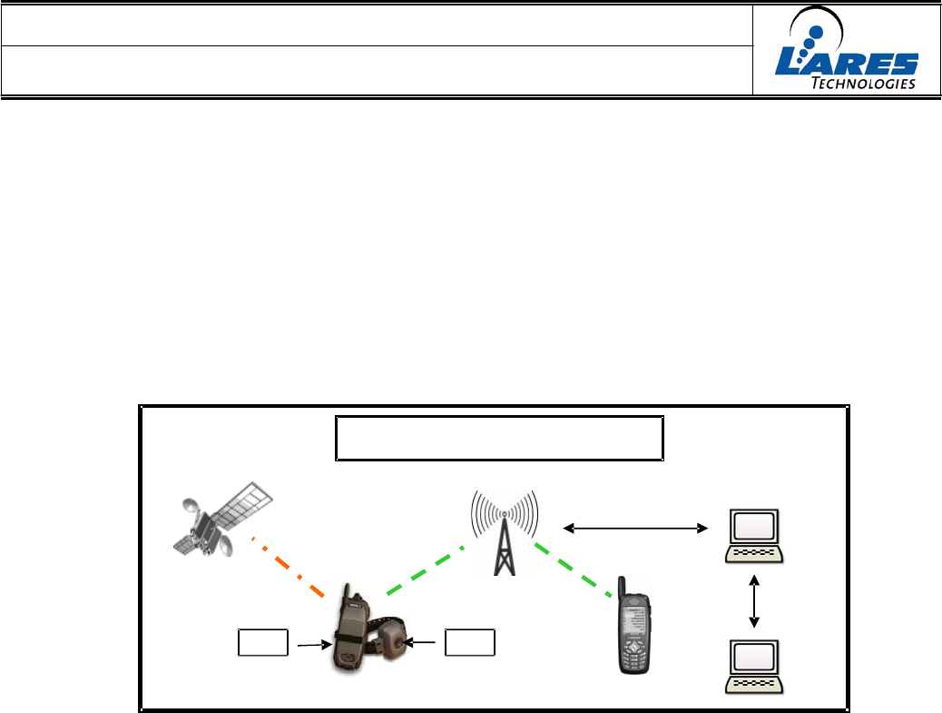
Lares Technologies has created a system for monitoring the location of criminal offenders
and tracking their position. This system is comprised of an ankle bracelet that is worn by
the offender, together with a cell phone that is carried by the offender. The BTX Ankle
Tether communicates to the Tracking/Reporting Unit (TRU) cell phone. The TRU cell
phone receives location information from the GPS satellite network, and it communicates
status and position via the cellular network. A system block diagram is show below:
The TetherTrack
System
TRU
BTX
1.1
P
RIMARY
F
UNCTIONALITY
OF
THE
BTX
A
NKLE
T
ETHER
The BTX Ankle Tether contains an ankle strap attached to an electronic module. The
electronic module monitors that the ankle strap is always connected, monitoring via both an
optical link and a conductive link on the ankle strap. The BTX Ankle Tether is powered by
a lithium battery. The BTX Ankle Tether includes one pushbutton (START button) on the
unit, used primarily for activation of the device.
The BTX Ankle Tether periodically communicates with the TRU cell phone to provide the
status of the ankle strap connection. In addition, the BTX Ankle Tether communicates
other status information to the TRU (e.g. such as battery status, and pushbutton activation.)
2.0 OPERATIONAL DESCRIPTION
The BTX Ankle Tether has two primary functions: detecting that the ankle strap has not
been removed and reporting the status of the strap to the TRU cell phone.
It has two main states: Off and On. The Off state is used during shipment from the factory
and when not in active use. The On state is used when active monitoring is desired.
3

USER MANUAL
BTX Ankle Tether
2.1
O
FF
S
TATE
The Off state is designed to be the lowest power state for the BTX Ankle Tether. In this
state, the device will NOT report any status conditions to the TRU cell phone.
The Off state is entered when a new battery is inserted and the power is applied or when
instructed to enter the state by the TRU cell phone while in the On state.
When the state is entered, the device will (re-)initialize the hardware, setup a wakeup
interrupt for the START button, and go into the Super Low Power mode.
If the START button is pressed, the BTX will wake and wait for communication with the
TRU cell phone.
If the TRU cell phone pairs with the BTX Ankle Tether, the TRU cell phone will send the
wakeup command and the device will enter the On state.
If the TRU cell phone is not present or does not pair with the BTX Ankle Tether, the BTX
will timeout and go into the BTX’s lowest power state and wait for another START button
press.
2.2
O
N
S
TATE
The On state is the normal state for a working BTX Ankle Tether. In this state, the
device will report any status conditions to the TRU cell phone over the communication
link per its configured settings and can be configured by the TRU cell phone.
The On state is entered when the device detects a START button press and the TRU cell
phone application has paired with the device and sent the wakeup command.
Once in the On state, the TRU can configure the BTX Ankle Tether by issuing
configuration commands and will receive fault status at predetermined intervals.
The On state is exited by: an Off command issued by the TRU cell phone or a low battery
condition that prevents the operation of the device.
In the On state, the device will monitor the following status conditions: strap conductive
link, strap optical link, battery voltage, and the START button and will report the status of
these conditions to the TRU cell phone.
Upon entering the state, the default configuration is set and the BTX updates the status and
sends the status to the TRU. The TRU will respond with a status acknowledge or with
another command indicating it wants to configure the device.
The command is interpreted and the appropriate action is completed, followed by the
device sending a command acknowledgement. The BTX Ankle Tether will accept other
configuration commands until there is no activity for the UART timeout period.
Once configuration is complete, the BTX will set the monitor timeout and wait.
When the monitor timeout has elapsed, the BTX will wake and get the device status.
4

USER MANUAL
BTX Ankle Tether
2.3
C
HECK
B
ATTERY
V
OLTAGE
The BTX Ankle Tether monitors the battery voltage to ensure it is changed at appropriate
intervals.
The battery voltage will have two thresholds: the operational threshold, and the low battery
threshold.
2.4
C
HECK
C
ONDUCTIVE
L
INK
The BTX Ankle Tether must ensure the strap remains connected. The strap contains a
conductive element that can be used to detect whether the strap has been disconnected.
2.5
C
HECK
O
PTICAL
L
INK
The BTX Ankle Tether must ensure the strap remains connected. The strap contains an
optical element that can be used to detect whether the strap has been disconnected.
5
USER MANUAL
BTX Ankle Tether
3.0 INSTALLATION INSTRUCTIONS
3.1
BTX
A
NKLE
T
ETHER
1. If necessary, open battery cover and install battery making sure to note + and –
placement. Screw down battery cover to “hand tight” using Bit Driver with Phillips bit.
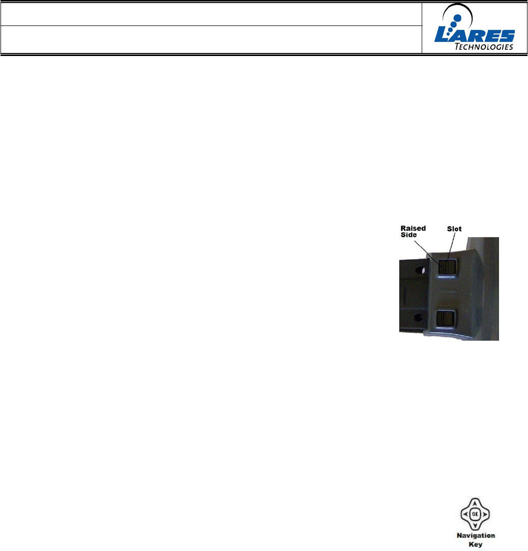
2. Insert t (arrow) end of strap into s (arrow) side of BTX and secure
using two pins. The slot in the top of the pin should be perpendicular
to the strap and the raised side of the top on the strap side. Push
down pins with thumb or finger until seated and a “click” is heard.
3. Size to offender’s ankle and cut strap on cut line using Strap
Cutter. Never cut the t (arrow) end of strap.
4. Secure BTX on offender’s ankle by inserting other end of strap into the BTX and using
two pins as described in Step 2 above.
3.2
T
RACKING
/R
EPORTING
U
NIT
-
TRU
5. Power on TRU and start TetherTrack application.
6. When SCANNING is displayed on screen push START Button on BTX on offender.
7. TRU will display the BTX number(s) (BTX – XXXXXX) that are in range.
If more than one BTX is displayed, scroll to the BTX you want
to pair with using the TRU’s Navigation Key. Push OK. Make
sure BTX number on display matches BTX number on offender.
8. If prompted: TetherTrack Requests User Location Permissions, push GRANT.
9. If prompted: Grant Request, select Always and push OK.
10. When pairing is complete, TetherTrack will suspend. Press OK to resume and display
the Status Screen. The application is operational while suspended.
6
USER MANUAL
BTX Ankle Tether
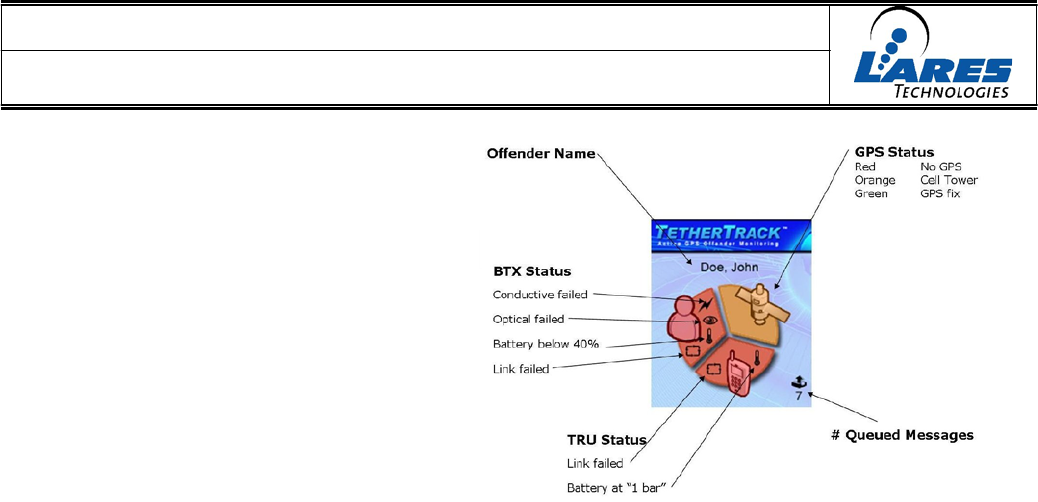
11. Check to make sure offender name
is correct.
12. If any Status has failed
(indicated in Red with icon) take
appropriate action to clear.
GPS may take a few
minutes and may require
moving the TRU near a window or
taking it outside.
13. After each Status
indicator has turned Green
place the TRU in its holster
and install the Holster
Lock.
TRU can now be given to offender to start program.
FCC Caution :To assure continued compliance, any changes or modifications not expressly approved
by the party responsible for compliance could void the user's authority to operate this equipment.
(Example - use only shielded interface cables when connecting to computer or peripheral devices).
FCC Radiation Exposure Statement
This equipment complies with FCC RF radiation exposure limits set forth for an uncontrolled
environment.
This device complies with Part 15 of the FCC Rules. Operation is subject to the following two
conditions:
(1) This device may not cause harmful interference, and
(2) This device must accept any interference received, including interference that may cause undesired
operation.
7