Climax Technology Co CLMTZB Clamp Meter User Manual
Climax Technology Co Ltd Clamp Meter Users Manual
Users Manual
Clamp Meter (CLMT-1ZBS)
CL-Meter-ZBS is a ZigBee Clamp Meter aim to monitor and report the total amount of electricity uses in your
facility by connecting the clamp onto the power cable.
The Clamp Meter utilizes ZigBee technology for wireless signal transmission. ZigBee is a wireless
communication protocol that is reliable and has low power consumption and high transmission efficiency. Based
on the IEEE802.15.4 standard, ZigBee allows a large amount of devices to be included in a network and
coordinated for data exchange and signal transmission.
The Clamp Meter serves as an end device in the ZigBee network. It can be included in the ZigBee network to
transmit signal upon activation, but cannot permit any other ZigBee device to join the network through the Clamp
Meter.
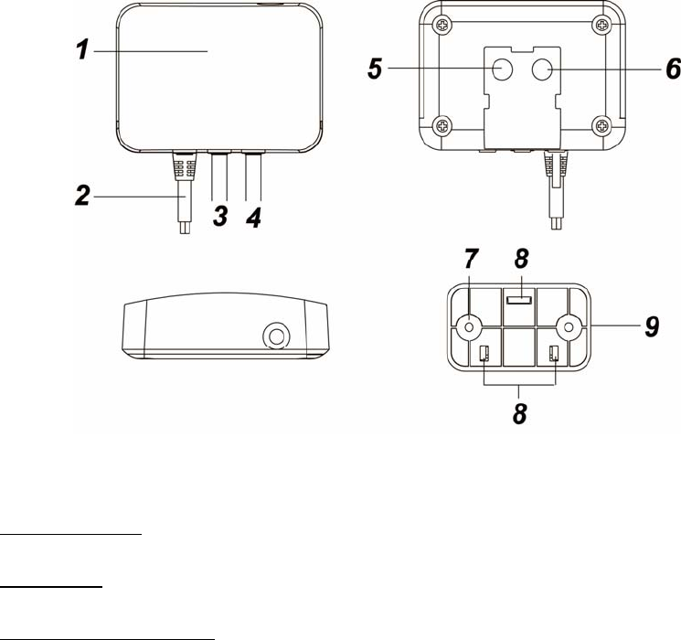
Parts Identification
1. Red LED
Flash twice quickly:
The Clamp Meter has successfully joined a ZigBee network.
Flashes once:
When Clamp Meter is reset.
Flash once every 20 minutes:
The Clamp Meter has lost its connection to its current ZigBee network.
2. AC Input cable
3. Current Transformer Cable (CT1)
4. Current Transformer Cable (CT2)
5. Function Button
-Press the button once to report the value of the meter to the ZigBee network.
-Press and hold the button for 10 seconds then release to reset the Clamp Meter.
6. Reserved
7. Mounting Hole
8. Mounting Hooks
9. Mounting Bracket
Installation
Wiring
WARNING
Wiring of the device should only be performed by a licensed electrician. The circuit box’s main breaker
should be turned off to perform installation.
The insertion hole wire specification is AWG18 or Ø 1.02 (mm²).
The Clamp specification is 60A Ø10mm
Please make sure the main power in your facility is also off before installing. Follow the steps below:
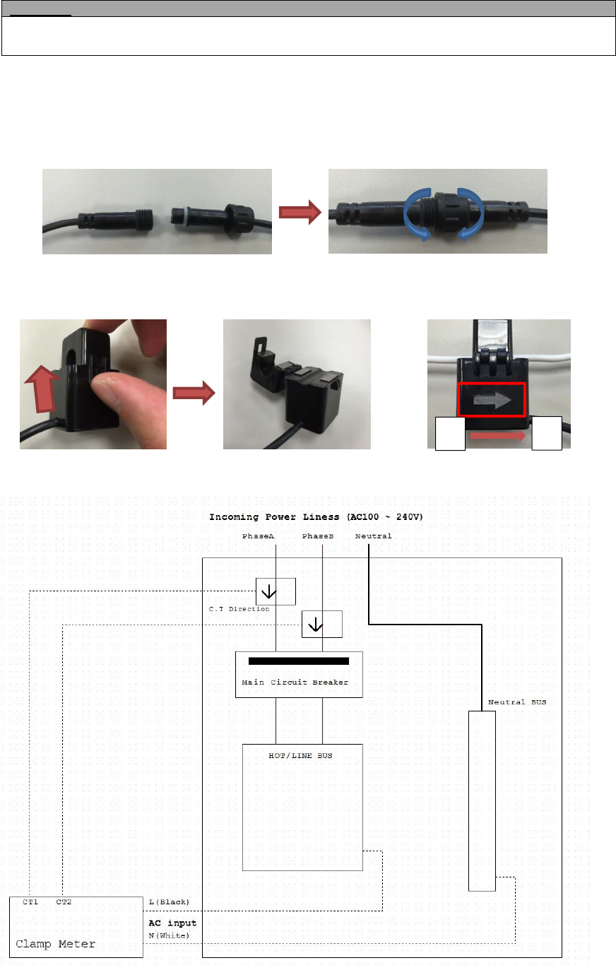
1. Connect AC Input cable to a socket near the Electrical Box to power on the Clamp Meter.
2. Attach both ends of the Current Transformer Cables first as picture shown below. Once you have attached
the Current Transformer Cable, start spinning the waterproof latch clock-wise until you have tighten and
secure both ends of the Current Transformer Cable.
3. Open the clamp as indicated by below picture. The clamp should be applied onto an electic cable The
arrow direction on the clamp need to point at the correct direction of the electricity current flows (KL). If
arrow is faced in reverse direction, the reading will display negative value (-) however it will not influence
the readings.
4. Follow the schematics below as an example; clip the clamps on the electricity cables on the 2 the
incoming power cable connected to the Main Circuit Breaker.
KL
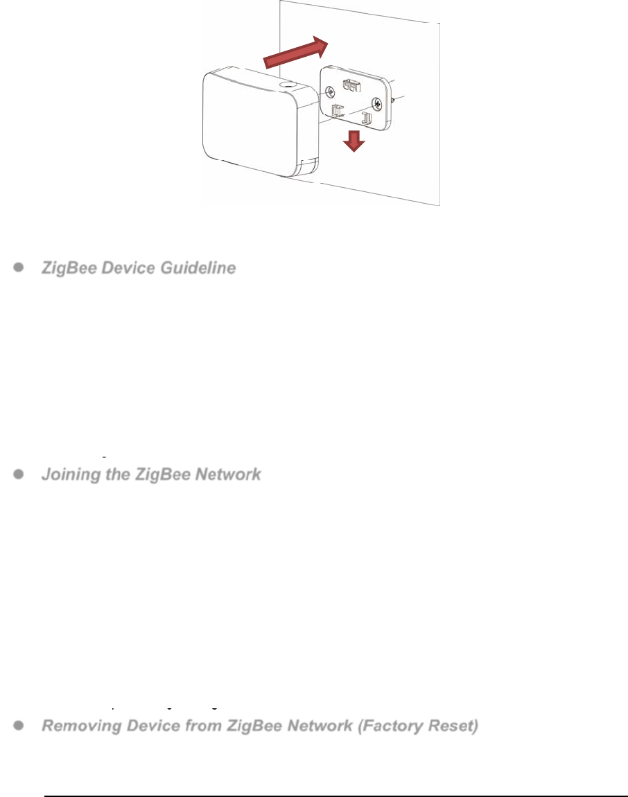
Mounting
The Clamp Meter has a mounting bracket for mounting purposes.
1. Use the mounting bracket as template to mark the two holes on the wall for installing screws.
2. Screw the mounting bracket onto the wall according to marked location. Install wall plugs if necessary.
3. Locate the hooks of the mounting bracket and line up the hooks with the mounting holes on the Clamp
Meter. Fit the hooks into the mounting holes as picture below. Installation is now complete.
ZigBee Network Setup
ZigBee Device Guideline
ZigBee is a wireless communication protocol that is reliable and has low power consumption and high
transmission efficiency. Based on the IEEE802.15.4 standard, ZigBee allows a large amount of devices to
be included in a network and coordinated for data exchange and signal transmission.
Due to the fundamental structure of ZigBee network, ZigBee device will actively seek and join network after
powering on. Since performing a task in connecting network may consume some power, it is required to
follow the instructions to avoid draining battery of a ZigBee device
- Ensure your ZigBee network router or coordinator is powered on before inserting battery into the ZigBee
device.
- Ensure the ZigBee network router or coordinator is powered on and within range while a ZigBee device is
in use.
- Do not remove a ZigBee device from the ZigBee network router or coordinator without removing the battery
from a ZigBee device.
Joining the ZigBee Network
As a ZigBee device, the Clamp Meter needs to join a ZigBee network to be able to read the meter. Please
follow the steps bellow to join the Clamp Meter into ZigBee network.
The Clamp Meter has 2 ZigBee Endpoints representing 2 current transformers. When joining ZigBee
network, it will be recognized as 2 separate ZigBee devices and will occupy 2 zones in your ZigBee
network coordinator.
1. Plug in the AC Input cable into the socket to power on the Clamp Meter.
2. Press and hold the function button for 10 seconds and release to search for existing ZigBee network.
Please make sure the permit-to-join feature on the router or coordinator of your ZigBee network is
enabled.
3. After joining the ZigBee network, the Clamp Meter will be registered in the network automatically. Please
check the ZigBee coordinator, security system control panel or CIE (Control and Indicating Equipment) to
confirm if joining and registration is successful.
4. Under normal operation, if the Clamp Meter loses connection to its current ZigBee network, the LED
indicator will flash every 20 minutes to indicate the situation. Please check your ZigBee network condition
and Clamp Meter signal range to correct the situation.
Removing Device from ZigBee Network (Factory Reset)
To remove the device from current ZigBee network, the Clamp Meter must be put to Factory Reset to
complete device removal. Factory Reset function will clear the Clamp Meter of its stored setting information
and prompt the device to search for new ZigBee network.
Before removing device, make sure the Clamp Meter is within current ZigBee network signal range
1. Delete the Clamp Meter from current control panel / CIE.
2. Press and hold the function button for 10 seconds, then release the button to reset device.
3. Upon reset, the Clamp Meter will clear current ZigBee network setting and transmit signal to ZigBee
coordinator to remove itself from current ZigBee network. It will then actively search for available ZigBee
network again and join the network automatically.

Energy Consumption Monitor
The Clamp Meter will transmit a signal from the clamp itself with its power consumption data every 10
minutes to the ZigBee network coordinator.
Reading from clamp on Current Transformer Cable CT-1 is reported to ZigBee Endpoint 0x01.
Reading from clamp on Current Transformer Cable CT-2 is reported to ZigBee Endpoint 0x02.
Whenever the Clamp’s energy output changes by +/- 2W, the Clamp Meter will automatically transmit
a signal with power consumption data to the ZigBee network coordinator for update.
The Clamp Meter transmits a signal with power data to coordinator whenever accumulated power
usage of the clamp increases by 0.1kW/hr.
The Clamp has an accuracy of +/- 5%.
To clear the clamp of its accumulated power consumption data, follow steps below:
1. Un-plug AC cable to power down Clamp Meter.
2. Press and hold the function button, while holding the button, power on the Clamp Meter by
re-plug in the AC cable.
3. Release the function button when red LED starts to quickly flash.
4. Un-plug and re-plug AC cable again, clearing is complete.
Maximum Operation Load
110V: 6600W and 60A
230V: 13800W and 60A.
Appendix (For developers only)
Scene Selector Cluster ID
Device ID: Consumption Awareness Device :0x000D
Endpoint: 0x01
Server SideClient Side
Mandatory
Basic (0x0000)Identify (0x0003)
Identify(0x0003)
Metering (0x0702)
Optional
NoneNone
Device ID: Consumption Awareness Device :0x000D
Endpoint: 0x02
Server SideClient Side
Mandatory
Basic (0x0000)Identify (0x0003)
Identify(0x0003)
Metering (0x0702)
Optional
NoneNone
Attribute of Basic Cluster Information
IdentifierNameTypeRangeAccess DefaultMandatory
/ Optional
0x0000ZCLVersionUnsigned 8-bit
integer 0x00 –0xffRead
only 0x01M
0x0001ApplicationVersionUnsigned 8-bit
integer 0x00 – 0xffRead
only 0x00O
0x0003HWVersionUnsigned 8-bit
integer 0x00 –0xffRead
only 0O
0x0004ManufacturerNameCharacter
String 0 – 32 bytes Read
only
Climax
TechnologyO
0x0005ModelIdentifierCharacter
String 0 – 32 bytes Read
only (Model Number)O
0x0006DateCodeCharacter
String 0 – 16 bytes Read
only
20160620O
0x0007PowerSource8-bit 0x00 –0xffRead M

Enumeration only
0x0010LocationDescriptionCharacter
String 0 – 32 bytes Read /
Write O
0x0011PhysicalEnvironment8-bit
Enumeration 0x00 –0xffRead /
Write 0x00O
0x0012DeviceEnabledBoolean0x00 –0x01Read /
Write 0x01M
Attribute of Identify Cluster Information
IdentifierNameTypeRangeAccess DefaultMandatory
/ Optional
0x0000IdentifyTimeUnsigned
16-bit integer 0x00 –0xffffRead /
Write 0x0000M
Attribute of the Metering Cluster Information
IdentifierNameTypeRangeAccess DefaultMandatory
/ Optional
0x0000IdentifyTimeUnsigned
16-bit integer 0x00 - 0xffffRead /
Write 0x0000M
Attribute of the Metering Cluster Information
IdentifierNameTypeRangeAccess DefaultMandatory
/ Optional
0x00CurrentSummation
Delivered
Unsigned
48-bit integer
0x000000000000
to
0xFFFFFFFFFFFF
Read
Only0x00M
Attributes of the Metering cluster Information
IdentifierNameTypeRangeAccess DefaultMandatory
/ Optional
0x00 UnitofMeasure 8-bit
Enumeration
0x00 to
0xFF
Read
Only 0x00 M
0x01 Multiplier Unsigned 24-bit
Interger
0x000000
to
0xFFFFFF
Read
Only 1 O
0x02 Divisor Unsigned 24-bit
Integer
0x000000
to
0xFFFFFF
Read
Only 0xF9 M
0x03 SummationFormating 8-bit BitMap 0x00 to
0xFF
Read
Only 0xF9 M
0x04 DemandFormating 8-bit BitMap 0x00 to
0xFF
Read
Only 0x94 O
0x06 MeteringDeviceType 8-bitMap 0x00 to
0xFF
Read
Only 0x00 M
Attributes of the Metering cluster Information
IdentifierNameTypeRangeAccess DefaultMandatory
/ Optional
0x00InstantaneousDemandSigned 24-bit
Integer
-8,388,607 to
8,388,607
Read
Only 0x00O
Federal Communication Commission Interference Statement
ThisequipmenthasbeentestedandfoundtocomplywiththelimitsforaClassBdigital
device,pursuanttoPart15oftheFCCRules.Theselimitsaredesignedtoprovide
reasonableprotectionagainstharmfulinterferenceinaresidentialinstallation.
Thisequipmentgenerates,usesandcanradiateradiofrequencyenergyand,ifnotinstalled
andusedinaccordancewiththeinstructions,maycauseharmfulinterferencetoradio
communications.However,thereisnoguaranteethatinterferencewillnotoccurina
particularinstallation.Ifthisequipmentdoescauseharmfulinterferencetoradioor
televisionreception,whichcanbedeterminedbyturningtheequipmentoffandon,the
userisencouragedtotrytocorrecttheinterferencebyoneofthefollowingmeasures:
.Reorientorrelocatethereceivingantenna.
.Increasetheseparationbetweentheequipmentandreceiver.
.Connecttheequipmentintoanoutletonacircuitdifferentfromthattowhichthereceiver
isconnected.
.Consultthedealeroranexperiencedradio/TVtechnicianforhelp.
FCCCaution:Toassurecontinuedcompliance,anychangesormodificationsnotexpressly
approvedbythepartyresponsibleforcompliancecouldvoidtheuser'sauthoritytooperate
thisequipment.(Example‐useonlyshieldedinterfacecableswhenconnectingtocomputer
orperipheraldevices).
FCCRadiationExposureStatement
ThisequipmentcomplieswithFCCRFradiationexposurelimitssetforthforanuncontrolled
environment.Thisequipmentshouldbeinstalledandoperatedwithaminimumdistanceof
20centimetersbetweentheradiatorandyourbody.
Thistransmittermustnotbeco‐locatedoroperatinginconjunctionwithanyotherantenna
ortransmitter.
Theantennasusedforthistransmittermustbeinstalledtoprovideaseparationdistanceof
atleast20cmfromallpersonsandmustnotbeco‐locatedoroperatinginconjunctionwith
anyotherantennaortransmitter.
ThisdevicecomplieswithPart15oftheFCCRules.Operationissubjecttothefollowingtwo
conditions:
(1)Thisdevicemaynotcauseharmfulinterference,and
(2)Thisdevicemustacceptanyinterferencereceived,includinginterferencethatmaycause
undesiredoperation.