Climax Technology Co CTC1052RV Wireless Medical Alarm System User Manual
Climax Technology Co Ltd Wireless Medical Alarm System Users Manual
Users Manual

+--E1
SEPT-07-2011

Table of Contents
1. Application Overview _______________________________________________________ 1
1.1. Identifying The Parts ____________________________________________________________ 1
1.2. The Power Supply ______________________________________________________________ 2
1.3. Insert GPRS/GSM SIM Card ______________________________________________________ 3
1.4. How to install the Control Panel__________________________________________________ 3
1.5. Compatible with Climax’s SMS Editor ____________________________________________ 3
2. Learn-in the Devices ________________________________________________________ 4
2.1. Learning Pendant #1 ____________________________________________________________ 4
2.2. Learning Pendant #2 ____________________________________________________________ 5
2.3. Remove Pendant #1 & #2 ________________________________________________________ 5
3. System Configuration _______________________________________________________ 6
3.1. Entering Programming Mode ____________________________________________________ 6
3.1.1. Local Programming Mode (Optional) __________________________________________________ 6
3.1.2. CTC-835 Programmer________________________________________________________________ 6
3.1.3. SMS Remote Programming___________________________________________________________ 6
3.2. Programming Your 1052_________________________________________________________ 6
3.3. SMS Remote Programming _____________________________________________________ 19
4. Operation _________________________________________________________________ 20
4.1. Idle Mode______________________________________________________________________ 20
4.1.1. Answering Incoming Phone Calls____________________________________________________ 20
4.1.2. Non-Emergency Speech Call ________________________________________________________ 21
4.1.3. AC Power Check Up ________________________________________________________________ 21
4.1.4. CTC-1052RV Low Battery ___________________________________________________________ 22
4.1.5. Devices Low Battery________________________________________________________________ 22
4.1.6. Automatic Check-in Report = Periodic Test Call_______________________________________ 22
4.1.7. Mobility Timer______________________________________________________________________ 22
4.1.8. No Pendant Present ________________________________________________________________ 22
4.1.9. Country Code ______________________________________________________________________ 23
4.2. Alarm Activation _______________________________________________________________ 23
4.4. Walk Test (Range Test)_________________________________________________________ 28
4.5. Global Test ____________________________________________________________________ 28
4.6. Factory Reset__________________________________________________________________ 29
5. Appendix__________________________________________________________________ 29
5.1. CID Event Code________________________________________________________________ 29
5.2. Tunstall Event Code____________________________________________________________ 30
5.3. Scancom Event Code __________________________________________________________ 30
5.4. CTC-1052RV Programming Command Table _____________________________________ 32
5.5. CTC-1052RV SMS Remote Programming Command Table ________________________ 34
1
3
1. Application Overview
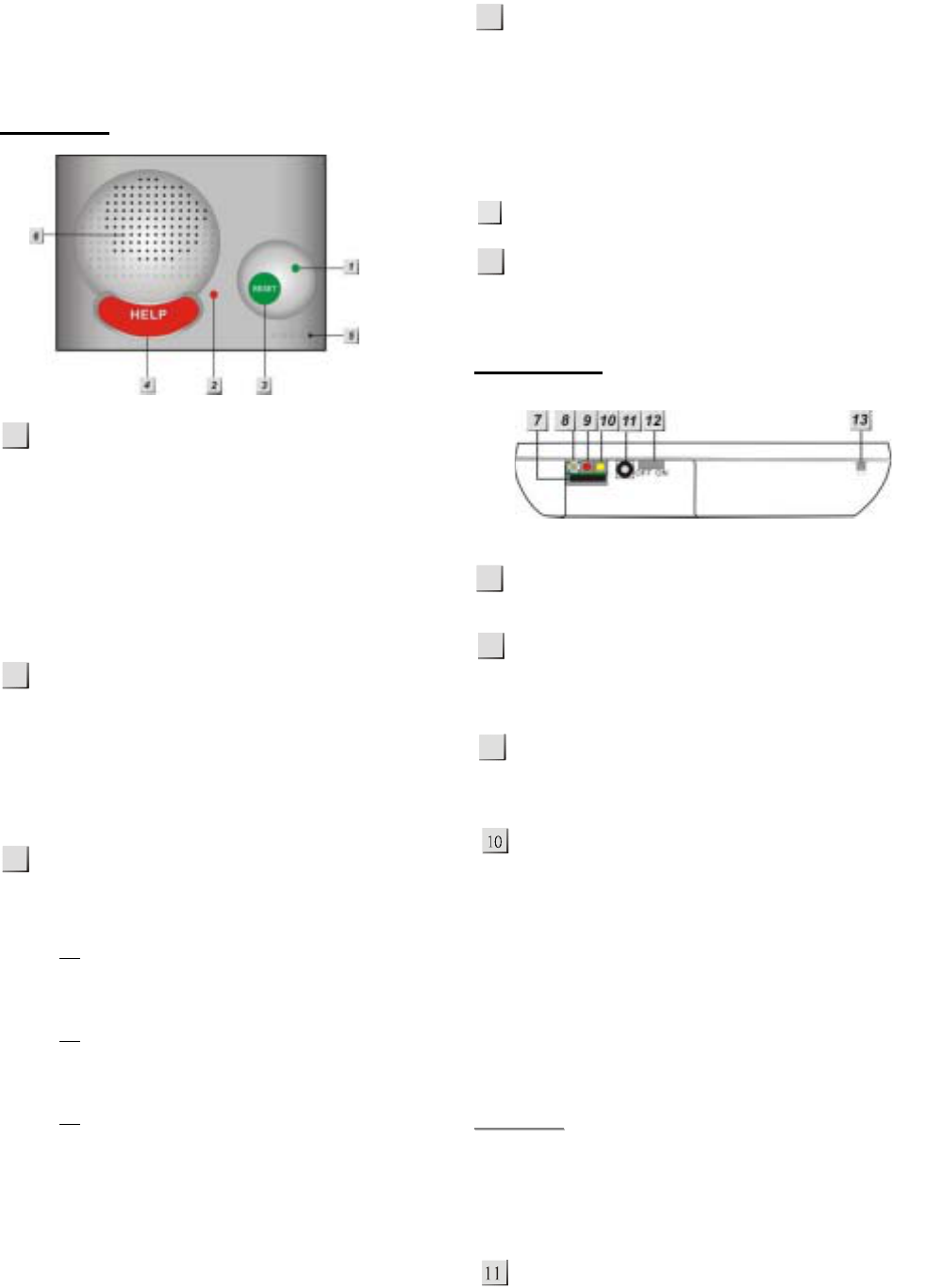
1.1. Identifying The Parts
TOP VIEW
GREEN LED
— ON: AC Power is ON.
— FLASH every second: AC Power
failure
— FLASH every 2 seconds: Panel or
Device Low battery
— QUICK FLASH every 2 seconds:
Supervision failure
RED LED
— ON: Off-hook / Waiting retry pause /
Ready to enter Programming Mode
(before entering PIN code)
— FLASH: Programming Mode /
Pendant Learning Mode
GREEN RESET BUTTON
— Press once in normal mode to reset
mobility timer (see command 44)
— Before CTC-1052RV dials out for
alarm reporting, press once to cancel
the alarm reporting
— During or at-the-end of conversation,
press once to terminate two-way
voice communication
— In Programming Mode, press once to
return to Idle Mode
— Press & hold for 3 sec: dial the Non-
Emergency call. (See section 4.1.2.)
— Press & hold for 6 sec: enter
Learning Mode
— Press & hold for 16 sec: disable
mobility setting
RED HELP BUTTON (with backlight)
— Back-lit disigned for easy access at
night
— Backlight illuminates when off-hook
— Backlight flashes during the waiting
period until help arrives
Microphone
Speaker
REAR VIEW
GPRS/GSM SIM Card Base
— This slot is for inserting a SIM card.
GPRS/GSM Reset Button
— Press & hold for 1 sec: GPRS/GSM
automatically resets
GPRS/GSM Module LED Indicator
(Red)
— FLASH: Normal operation
GPRS/GSM Fault Indicator (Yellow)
— FLASH every 5 seconds: SIM card
missing
— 2 FLASHES every 5 seconds: No
signal/reception
— 3 FLASHES every 5 seconds:
GPRS/GSM module abnormal
— 4 FLASHES every 5 seconds: SIM
card PIN code error
<
<N
NO
OT
TE
E>
>
) Fault indicator priorities: GPRS/GSM
module abnormal > SIM card missing
> No signal/reception > SIM card PIN
code error
DC Jack
— DC 12V 2A switching power
connection
1
4
6
8
9
7
5
2
2
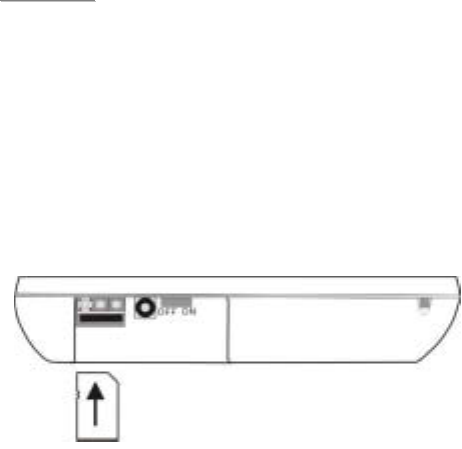
Battery Switch
Local Programming Telephone Unit
Input
— A special telephone cord to connect
CTC-1052RV and your phone unit
for Local Programming (optional).
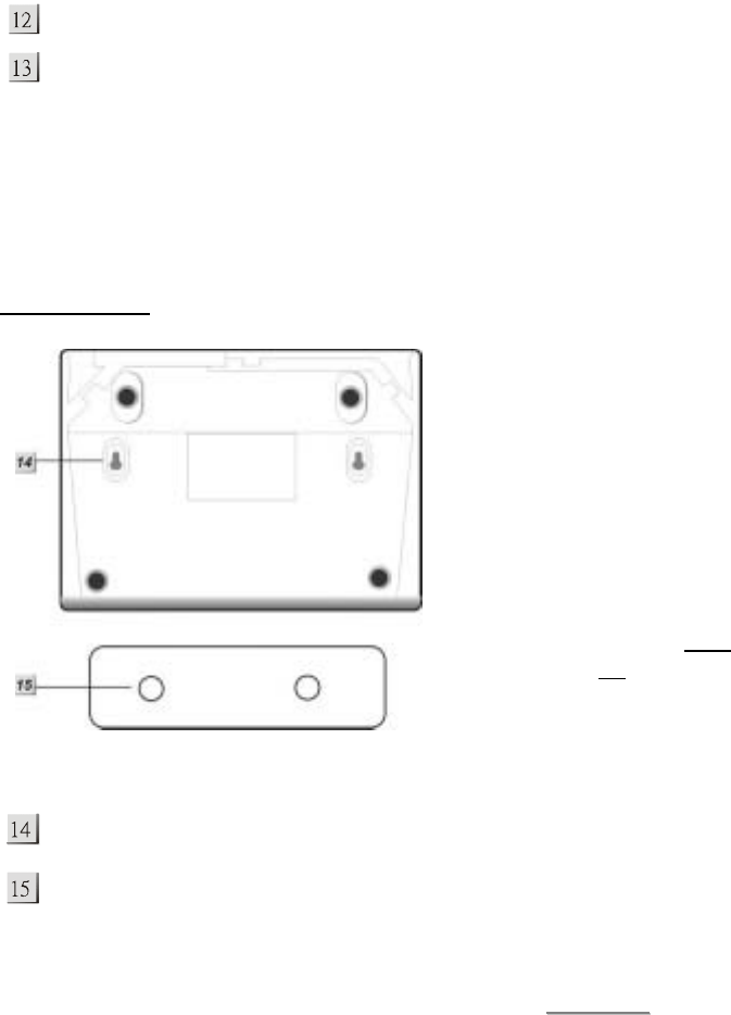
BACK VIEW
Mounting Holes
Mounting Bracket
1.2. The Power Supply
z An AC power adapter is required to
connect to a wall outlet. Be sure only to
use an adapter with the appropriate AC
voltage rating to prevent component
damage. A DC 12V output and 2A
switching power is generally used to
power CTC-1052RV.
z In addition to the adapter, there is a
rechargeable battery inside CTC-1052RV,
which serves as a back-up in case of a
power failure.
z The battery used is a Ni-Cd 7.2V 1300
mAH rechargeable battery.
z During normal operation, the AC power
adapter is used to supply power to CTC-
1052RV and at the same time recharge
the battery.
z When the battery is fully charged, it serves
as a back-up power source for a period of
at least 14.5 hours. It takes approximately
48 hours to fully charge the battery.
z The battery can be manually disconnected
by the battery switch located at the bottom
(covered with a rubber cap).
z Battery Switch is set as ON by factory
default. If switched to OFF, the battery will
not be charged when AC power is
connected, nor will it serve as a back-up
power source when AC power is missing.
<
<N
NO
OT
TE
E>
>
) Please make sure the battery switch is
slid back to ON position (as marked)
after manually disconnected the
rechargable battery.
3
1.3. Insert GPRS/GSM SIM
Card
CTC-1052RV Panel features built-in
GPRS/GSM communication facility to report to
the Monitoring Station.
z To Insert SIM card:
<
<N
NO
OT
TE
E>
>
) It is recommended to disable the SIM
card PIN code before inserting into the
Control Panel.
The GPRS/GSM SIM card base is located on
the rear side of the unit:
z Insert the SIM card with the chip side
facing up.
z Push to the furthest extend, then press on
the edge of the SIM card firmly to secure it.
z SIM Card will delete its SMS message
whenever the CTC-1052RV is powered on.
z To remove SIM card:
Press and release on the edge of SIM card, the
card will spring out.
1.4. How to install the Control
Panel
Locating a suitable position for the
Control Panel
z The Control Panel requires main power
and a constant GPRS/GSM reception.
z The Control Panel should be easily
accessible.
z The Control Panel should not be placed in
a damp location, such as a bathroom.
z The Control Panel should not be placed
close to any heat source, such as
microwave ovens, which can reduce
signal strength.
z The Control Panel should not be located
alongside other radio transmitting devices,
such as mobile phones, cordless phone,
or wireless computer network (Wi-Fi)
devices.
z Important: When drilling into a wall, ensure
there are no hidden cables or pipes.
Mounting the Control Panel
The Control Panel can be mounted on the wall
or wherever desired (e.g. on the table). Ensure
the Control Panel is fitted at approximately
chest height where the buttons, microphone,
and speaker can be easily accessed and
operated.
z Use the 2 holes of the Wall Mounting
Bracket as a template, mark off the holes’
positions.
z Drill 2 holes and insert the wall plugs if
fixing into plaster or brick.
z Screw the base to the wall.
z Hook the Control unit onto the Wall
Mounting Bracket (holding the unit with
the front facing you).
1.5. Compatible with Climax’s
SMS Editor
CTC-1052RV is compatible with Climax’s SMS
Editor, which is designed to facilitate SMS
remote programming via a PC. This tool allows
you to program the panel easily from your
computer, without sending complex SMS text
messages from a mobile phone.

4
2. Learn-in the Devices
There are two methods to learn in devices:
local learning and command learning. Total
10 sensors (including one talking pendant,
WTRV or WTRVS) are allowed to be learnt
into the system. And only one WTRV/ WTRVS
can be learnt into the system.
Local Learning:
You can use the local learning method to
learn in 2 devices only. Refere to 2.1
Learning Pendant # 1 to learn in the first
device and then 2.2 Learning Pendant #2 to
learn in the second one.
1. Users can enable CTC-1052RV to get into
the learning mode to learn in WTR- Series,
Fall Sensor or WTRV/ WTRVS.
2. WTRV/WTRVS is only allowed to be learnt
in by using the Local Learning method.
3. If you have learned the first device to the
system by following instructions in the 2.1
section, you are not allowed to use
Command 91 (Command Learning) to
learn in another device.
4. If you have learned the second device to
the sytem as instructed in the 2.2 section,
you are not allowed to use Command 92
(Command Learning) to learn in another
device.
Command Learning:
1. Users can use Command #91 ~ 94 to
learn in devices into the system,
including PIR Sensor, Smoke Detector,
Panic Button, Carbon Monoxide, Wrist
& Neck Transmitter, Water Sensor,
Pendant Transmitter, WTR- series and
Fall Sensor. Please refer to 3.2
Programming Your 1052RV:
Commands 91-94 for details.
2. You are not allowed to learn in WTRV/
WTRVS by using Command Learning
method.
3. Command 91 is designed to learn in
WTR- Series or Fall Sensor only.
4. Command 92 is designed to learn in
WTR- Series or Fall Sensor only.
5. Command 93 is designed to learn in
WTR- Series or Fall Sensor only for
silent reporitng.
6. Command 94 is designed to learn in
the following sensors:
PIR Sensor ----- PIR
Smoke Detector ---- SD
Carbon Monoxide ---- CO
Fixed Panic Button ---- PB
Wrist Transmitter ---- WTR
Pendant Transmitter ---- WTR
Water Sensor ---- WS
Fall Sensor
2.1. Learning Pendant #1
Refer to the following instruciton to learn in the
WTR- Series, Fall Sensor or WTRV/ WTRVS.
For Normal Wrist Transmitters (WTR-) or
Fall Sensor
1. Press and hold the RESET button of
CTC1052RV for 6 seconds until you hear
the double beep and followed by a long
beep.
2. The RED LED starts flashing. CTC-
1052RV is now in the learning mode.
3. Press and both the RESET and Pendant
#1 (WTR- Series or Fall Sensor) buttons
simultaneously until CTC-1052RV emit a
double-beep.
4. Pendant #1 has been learnt-in
successfully.
For Talking Pendant (WTRV/ WTRVS)
1. Press and hold the RESET button of
CTC1052RV for 6 seconds until you hear
the double beep and followed by a long
beep.
2. The RED LED starts flashing. CTC-
1052RV Pro is now in the learning mode.
3. Press and hold the WTRV/ WTRVS
button for 5 seconds until you hear a long
beep. The WTRV/ WTRVS’s Green LED
turn to RED.
4. The WTRV/ WTRVS is now in the learn
mode.

5
5. Press and hold the RESET button on
CTC-1052RV for 20 seconds and release
button until you hear two beeps, followed
by a long beep.
<
<N
NO
OT
TE
E>
>
) Meanwhile, WTRV/ WTRVS’s LED
turns from RED, then blink green to
steady green.
6. Start work test to check if WTRV/ WTRVS
is learnt in successfully.
7. Simply press the WTRV/ WTRVS button,
you will hear 6 contiunous beeps from
WTRV/ WTRVS.
8. During WTRV/ WTRVS’s beep, CTC-
1052RV will repond with 2 beeps
respectively. It indicates that WTRV/
WTRVS is within the operating range.
9. Press the Reset & Help button at the
same time to exit the learning mode. The
RED LED will dim to indicate that the
system is back to idle mode.
<
<I
IM
MP
PO
OR
RT
TA
AN
NT
T
N
NO
OT
TE
E>
>
) It is prohibited to learn in another or
the same Pedant twice, unless the
previously learnt-in pendant is
removed first.
2.2. Learning Pendant #2
Refer to the following instructions to learn in
the second device (WTR- Series, Fall Sensor
or WTRV/ WTRVS).
For Normal Wrist Transmitters (WTR-) or
Fall Sensor
1. Press and hold the RESET button of
CTC1052RV for 6 seconds until you hear
the double beep and followed by a long
beep.
2. The RED LED starts flashing. CTC-
1052RV is now in the learning mode.
3. Press and both the HELP and Pendant
#1 (WTR- Series or Fall Sensor) buttons
simultaneously until CTC-1052RV emits a
double-beep.
4. Pendant #2 has been learnt-in
successfully.
For Talking Pendant (WTRV/ WTRVS)
1. Press and hold the RESET button of
CTC1052RV for 6 seconds until you hear
the double beep and followed by a long
beep.
2. The RED LED starts flashing. CTC-
1052RV is now in the learning mode.
3. Press and hold the WTRV/ WTRVS
button for 5 seconds until you hear a long
beep. The WTRV/ WTRVS’s Green LED
turn to RED.
4. The WTRV/ WTRVS is now in the learn
mode.
5. Press and hold the HELP button on CTC-
1052RV for 20 seconds and release
button until you hear two beeps, followed
by a long beep.
<
<N
NO
OT
TE
E>
>
) Meanwhile, WTRV/ WTRVS’s LED
turns from RED, then blink green to
steady green.
6. Start work test to check if WTRV/ WTRVS
is learnt into successfully.
7. Simply press the WTRV/ WTRVS button,
you will hear 6 contiunous beeps from
WTRV/ WTRVS.
8. During WTRV/ WTRVS’s beep, CTC-
1052RV will repond with 2 beeps
respectively. It indicates that WTRV/
WTRVS is within the operating range.
9. Press the Reset & Help button at the
same time to exit the learning mode. The
RED LED will dim to indicate that the
system is back to idle mode.
<
<I
IM
MP
PO
OR
RT
TA
AN
NT
T
N
NO
OT
TE
E>
>
) It is prohibited to learn in another or
the same Pedant twice, unless the
previously learnt-in pendant is
removed first.
2.3. Remove Pendant #1 & #2
CTC-1052RV can be programmed to remove
Pendant #1 & #2 by Command 80, Command
81 or 82. Please refer to 3.2 Programming
Your 1052RV: Commands 80, 81 or 82 for
details.

6
3. System Configuration
3.1. Entering Programming
Mode
Two CTC-1052RV programming modes are
available: Local Programming Mode and
Remote Programming Mode.
<
<N
NO
OT
TE
E>
>
) GPRS/GSM will be powered down
when in Programming Mode. When
AC Power resumes or when exits from
Programming Mode, GPRS/GSM will
be powered on again.
3.1.1. Local Programming Mode
(Optional)
From Idle mode, follow the steps below to
enter Local Programming mode.
Step 1. Plug in the telephone set into
LOCAL PROGRAMMING input
located on the rear side of CTC-
1052RV.
Step 2. Pick up the handset.
RED LED lights up.
Step 3. Enter default ACCESS CODE, 1111
followed by #.
Step 4. CTC-1052RV will emit 2 short beeps
and the red LED starts to flash,
indicating it is in Programming Mode.
Step 5. Proceed to program system by
referring to the Commands in section
3.2 Programming Your 1052.
<
<N
NO
OT
TE
E>
>
) Local programming is prohibited when
AC Power fails.
) The first digit of Access Code must be
entered within 15 seconds, otherwise
CTC-1052RV will exit automatically.
) Failure to enter the correct Access
Code within 2 minutes will cause
CTC-1052RV to exit the Programming
mode automatically.
) To exit Programming mode, enter 99
followed by #, or place the handset
on hook, or disconnect the
Programming telephone set.
3.1.2. CTC-835 Programmer
CTC-835 is a powerful programming tool (sold
separetely) that features a built-in keypad and
LCD display to help you to program the
medical alarm panels effeciently and
conveniently. It also features Once-for-All
Uploading, which allows you program on a
computer via the supplied Pilot software and
you can then upload all the settings to the
medical alarm panel simultaneously with a
single mouse click.
For detailed usages, please refer to the
Operation Manual of CTC-835 Programmer.
3.1.3. SMS Remote Programming
CTC-1052RV can be remotely programmed via
SMS commands. Please refer to section 3.3
SMS Remote Programming for usage.
3.2. Programming Your 1052
z How to enter Commands?
Please make sure CTC-1052RV is in
Programming Mode (RED LED flashes
continuously) before trying any CTC-
1052RV Command Functions. Please refer
to section System Configuration, Entering
Programming Mode.
z Follow the protocol below to command
CTC-1052RV:
CC #DTMF
ACK Function
Selection #DTMF
ACK
1. 2. 3. 4. 5. 6.
1. CC = 2-digit DTMF Command
2. # = Termination of the DTMF Command
3. ACK = DTMF Command
Acknowledgement
On CTC-1052RV:
Short beep: Command succeeded
Long beep: Command failed

7
On the programming phone set:
Short beep: Command succeeded
Long beep: Command failed
4. Function Selection = According to
different Command you will have different
entering in this part, e.g. Tel. Number,
Account number, etc.
5. # = Terminates Function Selection
6. ACK = Function Selection
Acknowledgement
On CTC-1052RV:
Short beep: Command succeeded
Long beep: Command failed
On the programming phone set:
Short beep: Command succeeded
Long beep: Command failed
z Follow the Command Steps to program
your CTC-1052RV:
Step 1. Enter Command number (DTMF
Numeric Command, ex. (01), (02)…)
Step 2. Press (#) to terminate the DTMF
Command.
Step 3. One short beep will be heard for
successful Command entry.
Step 4. Enter the desired Command function
number.
Step 5. Enter (#) to terminate the Command
Operation.
Step 6. CTC-1052RV will emit a short beep,
indicating successful programming.
The maximum interval between key strokes is
2 minutes. Otherwise, commands will be
ignored and CTC-1052RV will automatically
exit to Idle Mode.
z Any erroneous programming must be
rectified and program again correctly.
Command 01-04
Telephone Number Programming
z Used to program the 1st - 4th Tel. numbers
respectively.
z To program the 1st Tel. number: enter (01)
followed by (#). After one short beep, enter
(telephone number) followed by (#). CTC-
1052RV will emit one beep signaling the 1st
Tel. number was programmed successfully.
z Likewise, the 2nd, 3rd or 4th Tel. numbers can
be programmed using Command (02), (03)
or (04) respectively.
<
<N
NO
OT
TE
E>
>
) When entering the phone number,
entering (À) means a 3-sec. pause.
(ex. Switchboard system, extension,
etc.)
) Up to 20 digits including (À) are
allowed for each telephone number.
Delete Telephone Number:
z To delete the 1st Tel. number, enter (01)
followed by (#), after one short beep, enter
another (#). CTC-1052RV will emit another
short beep, signaling the 1st Tel. number is
erased.
z Likewise, you can erase the respective 2nd,
3rd or 4th Tel. Numbers, by following the
above procedure.
Command 05-06
Select Telephone Number for Alarm
Reporting and Status Reporting
<
<I
IM
MP
PO
OR
RT
TA
AN
NT
T
N
NO
OT
TE
E>
>
If the Tel. number is selected in
Commands #5, #6 and #7, then
Command #7 holds the top priority to
overwrite the setting. The Tel. number
selected in Command #7 will not be
used for alarm and/or status reporting.
z Command (05): Select which telephone
number & GPRS/IP (1-6) is/are to be used
for Alarm Reporting.
z Command (06): Select which telephone
number & GPRS/IP (1-6) is/are to be used
for Status Reporting.

8
z Available Key-in options:
Tel. Number /
IP Address
Function Selection
Sequence
1st Tel. # (1)
2nd Tel. # (2)
3rd Tel. # (3)
4th Tel. # (4)
5th GPRS1 # (5)
6th GPRS2 # (6)
1st & 2nd Tel. #s (12)
1st & 3rd Tel. #s (13)
1st & 4th Tel. #s (14)
1st Tel & 5th GPRS. #s (15)
1st Tel & 6th GPRS. #s (16)
2nd & 3rd Tel. #s (23)
2nd & 4th Tel. #s (24)
2nd Tel & 5th GPRS. #s (25)
2nd Tel & 6th GPRS. #s (26)
3rd & 4th Tel. #s (34)
3rd Tel & 5th GPRS. #s (35)
3rd Tel & 6th GPRS. #s (36)
4th Tel & 5th GPRS. #s (45)
4th Tel & 6th GPRS. #s (46)
5th & 6th GPRS. #s (56)
1st, 2nd & 3rd Tel. #s (123)
1st, 2nd & 4th Tel. #s (124)
1st , 3rd & 4th Tel. #s (134)
2nd, 3rd & 4th Tel. #s (234)
1st, 2nd, 3rd & 4th Tel. #s (1234)
1st, 2nd, 3rd, 4th Tel. & 5th
GPRS. #s (12345)
1st, 2nd, 3rd, 4th Tel. 5th &
6th GPRS. #s (123456)
z Factory default is set as (123456). Alarm &
Status will be reported to all of 4 Telephone
Numbers+2 GPRS (IP).
<
<N
NO
OT
TE
E>
>
) The Tel. number selected in Command
#7 will not be used for alarm and/or
status reporting, even if it is selected
in command #5 and/or #6.
) When multiple Tel. numbers are
selected, CTC-1052RV will always
dial in respective programmed order.
) The latest Command (05-06) setting(s)
will overwrite any previously enter
setting(s).
) When CTC-1052RV reports, GPRS has
higher proity than phone reporting.
Command 07
Select Telephone Number for Non-
emergency call
z This command is used to select which
telephone number will be used for non-
emergency call.
z The selected Tel. number will not be used
for alarm, status, other alarm and/or
Mobility reporting, even if it is selected in
command #5 and/or #6.
z Available key-in options:
Tel. Number Function Selection
Sequence
Disable (0)
1st Tel. # (1)
2nd Tel. # (2)
3rd Tel. # (3)
4th Tel. # (4)
z Factory default is set as (0) disable. Non-
emergency call will be reported to all of 4
Telephone Numbers.

9
z Please refer to section 4.1.2 for more
information.
z When the Control Panel has the AC failure
condition, non-emergency can be made by
pressing and hold the Reset button for 3
seconds. Then the main unit will emit a
beep every 2 seconds for 20 seconds until
the Red LED lights on, indicating the GSM
module wakes up to call out. Before the
Red LED lights on, you can press the
Reset Button to cancel calling.
<
<N
NO
OT
TE
E>
>
) Command #07 can’t be used for GPRS
setting.
Command 10-14
Account Number Programming
z Commands (10-14) are used to set the
account number for the telephone numbers
used for Digital Reporting.
z Command (10): Set the same account
number for all telephone numbers.
z Command (11-14): Set the account
numbers for the 1st-4th Tel. numbers used
for Digital Reporting respectively.
z In (Function Selection) key in 4 or 6 digit
Account Number.
Command 20-24
Reporting Method
z Commands (20-24) are used to program
the Alarm reporting method for each Tel.
Number.
z Command (20): Program the same Alarm
Reporting Method for all 4 Tel. Numbers.
z Command (21-24): Program the alarm
reporting method for the 1st-4th Tel.
Numbers respectively.
z Available Options:
Method Function
Selection
(0) Contact ID Digital
Reporting (1) Scancom
Method (2) Tunstall
Speech
Method (3) Open Two-way
communication
SMS
Reporting
Method
(4) SMS (CID)
z (0), Contact ID, is set as factory default for
all 4 telephone Numbers.
<
<N
NO
OT
TE
E>
>
) The latest Command (20-24) setting(s)
will overwrite any previously entered
setting(s).
) If any of Digital Reporting Methods
is selected:
Once alarm or emergency data is
successfully transmitted, CTC-1052RV
will automatically enter specific
Follow-On and/or Call Back Mode as
specified by Command (38).
) If Speech Method is selected:
After the dialing for alarm/emergency
trigger is successful, CTC-1052RV
opens a two-way voice communication
between the Call Recipient and CTC-
1052RV for 1-10 minutes (set by
Command #46).
If the Call Recipient needs more talk
time, they can press any keys except
9 on their phone set to add another 1-
10 minutes (set by Command #46).
To terminate the call, press (9) or
RESET BUTTON on CTC-1052RV.
During the Speech period, CTC-
1052RV will emit two beeps via the
telephone handset to alert the call
recipient the remaining time of 20 & 10
secs.
During the Speech period, if there is
no any DTMF command pressed, the
call will automatically hang-up and be
recorded as an unsuccessful call. It
will retry up to a max. of 4 times on
each Tel. Number accordingly.
) If any of SMS Reporting Methods is
selected:
CID sent over SMS is a backup path

10
when alarm can’t go through in digital
reporting method. Once alarm or
emergency data is successfully
transmitted, the CTC-1052RV will
automatically send out a SMS (CID)
Message.
Command 31
Ringer Enable for Incoming Calls
z CTC-1052RV can be programmed to emit
a ring tone as an audio alert, or silent for
incoming calls.
Function Selection Result
(0) OFF
(Ring Tone Disable)
(1) ON
(Ring Tone Enable)
z Factory Default is set as (0), OFF.
<
<N
NO
OT
TE
E>
>
) If the function is set to ON, you can
answer the incoming call by pressing
the RED HELP BUTTON or Pendant
Button.
) The time-out period for the incoming
call is 30 minutes. During the
communication, CTC-1052RV will
emit two beeps via the telephone
handset to alert the call recipient the
remaining time of 20 & 10 secs.
) Press any DTMF keys (except
DTMF#9) can extend another 30 min.
) To terminate the incoming call: (1)
press the green reset button on CTC-
1052RV; or, (2) press DTMF #9 from
the call recipient’s end.
) During the AC Power failure period,
Ring Tone is automatically disabled.
Command 32
Audible Fault Alert
z CTC-1052RV can be programmed to emit
detected and existent Fault Alert Beeps at
every 30 secs.
Function Selection Result
(0) OFF
(No Warning Beep)
(1) ON
(With Warning Beep)
z Factory Default is set as (0), OFF.
z The fault situation includes Low Battery
Fault (for both CTC-1052RV and Devices)
and AC Failure.
Command 33
Help Arrived Signaling
This function is only available for the digital
Contact ID reporting method.
z It is used for the Monitoring Center
personnel to confirm if the help has arrived
for the user or not.
z If Help Arrived Signaling is set to ON, once
the Alarm Reporting is completed, the
RED HELP BUTTON will start to flash.
Press the GREEN RESET BUTTON when
the Help arrives, and CTC-1052RV will
report to monitoring center and the RED
BUTTON will stop flashing.
z If Help Arrived Signaling is set to OFF,
once the Alarm Reporting is completed,
CTC-1052RV will return to idle mode.
Function Selection Result
(0) OFF
(Disable)
(1) ON
(Enable)
z Factory Default is set as (0), OFF.
<
<N
NO
OT
TE
E>
>
) If the GREEN RESET BUTTON is not
pressed within 15 minutes, CTC-
1052RV will send one more Help Call
report to summon help and inform the
Monitoring Center that no help has
arrived within the past 15 minutes.

11
Command 34
Emergency Button Enable
z The RED HELP BUTTON can be enabled
or disabled to send an Emergency alarm
report:
Function
Selection Result
(0) OFF
(Deactive)
(1) ON
(Active)
z Factory Default is set as (1), ON.
<
<N
NO
OT
TE
E>
>
) When this function is programmed as
OFF, the RED HELP BUTTON is
deactivated.
) When this function is programmed as
ON, the RED HELP BUTTON is
activated. When pressed, it will send
an Emergency alarm report to the
Monitoring Station.
Command 35
Silent Mode
z CTC-1052RV can be selected to operate in
Silent Mode. This will mute all normal
operation warning beeps, guard time
tone, key tone and ring.
<
<N
NO
OT
TE
E>
>
) In silent mode, the speaker still
functions normally for two-way voice
communication.
Function
Selection Result
(0) ON
(Silent)
(1) OFF
(Normal)
z Factory Default is set as (1), OFF.
Command 37
AC Fault Report
z The CTC-1052RV can be programmed to
send a Fault Report when an AC power
failure is detected.
Function Selection Result
(0) OFF
(Send No Report)
(1) ON
(Send Report)
z Factory Default is set as (1), ON.
<
<N
NO
OT
TE
E>
>
) Reporting will only be made after a
continuous one hour of AC Fault
condition is detected.
Command 38
Follow-On & Call-Back Function
z The Command is available for Digital
Reporting Methods (when Command #20 -
#24 is set as (0), (1) or (2))
Function Selection Result
(0) Follow-On
(1) Call-Back
(2) Follow-On & Call-Back
z Factory Default is as (0), Follow-On.
z When this function is programmed as (0),
after a successful alarm reporting
(triggered by pressing the Help button on
the Medical Panel) to the Monitoring
Center, CTC-1052RV will automatically
enter the Follow-On mode as specified by
Command (45). If the alarm is triggered by
a Talking Pendant (WTRV/WTRVS), the
system will automatically enter to the “Wait
for Command” mode (skips to check
Command 45) and wait for the DTMF 2
signal pressed by the Monitoring Center to
set up the two-way communication
between WTRV/WTRVS and the
Monitoring Center.
z When this function is programmed as (1),

12
after a successful alam reporting (triggered
by pressing the Help button on the Medical
Panel) to the Monitoring Center, CTC-
1052RV will automatically hang up the line
and start a 5-minute waiting period to auto
answer any incoming phone calls from the
Monitoring Center. The Monitoring Center
personnel should enter an authorized
access code (default: 1111), followed by (#)
to set up the two way communication
between CTC-1052RV and the Monitoring
Center.
If the alarm is triggered by a Talking
Pendant (WTRV/WTRVS), during the 5-
minute waiting period, the system will
wait for an authorized access code
(default:1111), followed by (#) to open the
two-way communciation between
WTRV/WTRVS and the Monitoring Center.
z When this function is programmed as (2),
after a successful alarm reporting
(triggered by pressing the Help button on
the Medical Panel) to the Monitoring
Center, CTC-1052RV will automatically
enter the Follow-On mode as specified by
Command (45). If the alarm is triggered by
a Talking Pendant (WTRV/WTRVS), the
system will automatically enter the “Wait
for Command” mode (skips to check
Command 45) and wait for the DTMF 2
signal pressed by the Monitoring Center to
set up the two-way communication
between WTRV/WTRVS and the
Monitoring Center.
Once Follow-On Mode is terminated, CTC-
1052RV will automatically start a 5-minute
waiting period to auto answer any incoming
phone calls from the Monitoring Center. The
Monitoring Center personnel should enter
an authorized access code (default: 1111),
followed by (#) to set up the two way
communication between CTC-1052RV and
the Monitoring Center. If the alarm is
triggered by a Talking Pendant
(WTRV/WTRVS), during the 5-minute
waiting period, the system will wait for an
authorized access code (default:1111),
followed by (#) to open the two-way
communciation between WTRV/WTRVS
and the Monitoring Center.
<
<N
NO
OT
TE
E>
>
) During two-way communication, you
can use DTMF command to switch the
communicating method. Please refer to
section 4.2. Alarm Activation.
) The Access Code must be entered
within 15 secs. Otherwise, CTC-
1052RV will disconnect the call
automatically.
) To terminate the call, press DTMF (9)
or RESET BUTTON on CTC-1052RV.
) If the 5-minute waiting period is up,
CTC-1052RV will automatically exit
this waiting mode and return to idle
mode.
) During the AC Power failure period,
Call-Back function is automatically
disabled.
Command 40
Set Access Code
z The Access Code is used to enter
Programming Menu (locally or remotely),
and the Call-Back Function.
z It consists of 4 digits and has been set to
(1111) as factory default. Before you set
your own Access Code, (1111) must be
keyed in.
z To set a new Access code; enter the
desired (4-digit number) in Function
Selection.
Command 42
Guard Time Delay
This command is deisgned for any
compitable sensor, except Fall Sensor.
z CTC-1052RV can be programmed to delay
alarm reporting from (00) (instant reporting)
to (99) seconds.
z During this time period, a continuous series
of beeps will be emitted to alert user.
z If a false alarm is triggered by any
compitable device, it can be cancelled
within the Guard Time Delay.
Function
Selection Result

13
(00) INSTANT REPORTING
(01) - (99) DELAY
z Factory Default is (10), 10 SECONDS.
<
<N
NO
OT
TE
E>
>
) Emergency alarm cannot be cancelled
after the Guard Time is elapsed.
) The Guard Time Delay for Fall Sensor
is set by Command 66. Command
66 is used if a fall is detected.
) If an emergency alarm is triggered by
pressing the Active Button on Fall
sensor, the guard time delay time is
restricted to Command 42, rather
than Command 66.
) If the Guard Time Delay Time set by
Command 42 is less than the delay
time set by Command 66, the system
will follow the setting of Command 42
to respond accordingly if an alarm is
triggered.
Command 43
Periodic Test Call
z CTC-1052RV can be programmed to make
test calls periodically from (00) (no test call)
to every (1) - (7) or 30 days:
Function Selection Result
(0) OFF
(1) - (7) 1 - 7 DAYS
(8) 30 DAYS
z Factory Default is set as (0), OFF.
<
<N
NO
OT
TE
E>
>
) Whenever programming mode is
accessed, CTC-1052RV will reset the
Periodic Test Call timer.
Command 44
Mobility Timer
This function monitors user movement around
the premises and sends an inactivity report to
the Monitoring Center if the user fails to reset
the inactivity timer.
z This will disable or enable the Inactivity
Timer with selectable count down periods.
Options are:
Function
Selection Result
(00) DISABLE
(01) 1HR
(02) 2HR
..........
.........
(36) 36HR
z Factory Default is set as (00), DISABLE.
<
<N
NO
OT
TE
E>
>
) The Mobility Timer counting down can
be reset by:
1. Pressing the RESET button on
CTC-1052RV, or,
2. Movement detected by PIR
Detector
3. Only workable by entering 2 digits.
) When Mobility Timer expires and no
reset signal is received, CTC-1052RV
starts to emit one long beep every 5
minutes to alert the user. After 30
minutes, if reset signal is not received,
a mobility alarm reporting will be made.
) The reporting method for mobility alarm
is the same as the emergency alarm.
The report will be sent based on your
reporting methods without guard time
waiting.
) When (00) is selected, no code is sent
to Monitoring Center.
) When CTC-1052RV is in idle mode,
press and hold the green reset button
for 16 seconds, until you hear a long
beep. Then release the button; the
Mobility function will be disabled.

14
Command 45
Follow-On Mode Choice
z This Command is only available for Digital
reporting with Command #38 set as (0) or
(2).
z It is used to select the Follow-On Choice
for CTC-1052RV after it has made a report
to the Monitoring Center.
z After reporting, CTC-1052RV can wait for
further commands, or enter a Two-Way
Full Duplex Communication, or Listen-In
Half Duplex Communication immediately
according to the setting under this
command:
Function
Selection Result
(0) WAIT
COMMAND
(1) LISTEN
(2) TWO WAY
z Factory Default is set as (2), TWO WAY.
<
<N
NO
OT
TE
E>
>
) When (0) is selected, after CTC-
1052RV has made an alarm report to
the Monitoring Center, it will wait for 1-
10 minutes (set by Cammand 46), and
then follows the DTMF commands that
are received from the Central
Monitoirng Station for action.
If no command is received after the
waiting period, the system will
automatically return to Idle mode.
) When (1) is selected, after CTC-
1052RV has made a report to the
Monitoring Center, it will automatically
enter Listen-In Half Duplex for 1-10
minutes (set by Command 46) allowing
the Monitoring Center Personnel to
listen in to what is happening on the
other side.
) When (2) is selected, after CTC-
1052RV has made a report to the
Monitoring Center, it will immediately
enter a Two-way Full-duplex
Communication mode for 1-10
minutes (set by Command 46), that
gives the user the ability to speak
directly with the Monitoring Center
Personnel.
) If either Scancom or Tunstall reporting
format is selected, CTC-1052RV will
ignore Command #45 selections. It will
always open a Two-way voice for
Follow-On choice.
) If an alarm is triggered by
WTRV/WTRVS, the Monitoring
Center personnel has to press the
DTMF 2 over 1 second to open the
two-way communication between
WTRV/WTRVS no matter what
Follow-On choice you have set.
Command 46
Follow-On Mode & Two-Way Period
z This command is used to program the
allowable time duration for Follow-On
mode choice (Commend #45) & Two-way
voice communication period (Speech
mode). It can be set from (01) (1 minute) -
(10) (10 minutes).
Function Selection Result
(01) 1 MINUTE
(02) 2 MINUTES
(03)-(10) 3-10 MINUTES
z Factory default is set as (05) 5 minutes.
The allowable time duration for either Wait
Command, Two-way, Listen-In Only or
Two-way voice comminucation in
Speech mode is two mins. During the 2-
min period, CTC-1052RV will emit two
beeps via the telephone handset to alert
the call recipient the remaining time of 20 &
10 secs. Pressing assigned DTMF key can
extend another 1-10 minute(s).
Command 47
Off-Set Time
z After the Control Panel‘s power is supplied,
the time of the Check-in Report starts
calculating.
z According to the setting of Off-Set Time,
the Control Panel will send Check-in
Report once, and then send report

15
according to the setting of Command 43
- Test call.
Function
Selection Result
(1) 1 Hour
(2) 2 Hour
(3) 3 Hour
(4) 4 Hour
(5) 8 Hour
(6) 12Hour
z Factory default is set as (1) 1 Hour. When
the Off-Set Time is reset in programming
Mode, the time of the Off-Set period will
recalculate.
z Off-Set time Report will be sent only once,
and then the Control Panel sends Check-in
Report according to setting of period test
call, unless the Control Panel restarts or
the Off-Set time is reset.
<
<N
NO
OT
TE
E>
>
) Whenever programming mode is
accessed, CTC-1052RV will reset the
Off-Set timer.
Command 49
Supervision
This function is not available for the digital
Scancom reporting method.
z This option is used to enable system
Supervision function. Once enabled, CTC-
1052RV will be able to receive the check-
in signals from Wrist Pendants (WTR-) to
indicate their proper functioning.
Function
Selection Result
(0) Disable
(1) 4 Days
(2) 5 Days
(3) 6 Days
(4) 7 Days
(5) 8 Days
(6) 9 Days
(7) 10 Days
z Factory default is set as (0) Disable. No
code is sent to Monitoring Center.
z When the supervisory timer expires and no
supervision signal is received from WTR-,
the supervisory alarm reporting will be
made.
z The reporting method for supervisory alarm
is the same as the emergency alarm. The
report will be sent based on your reporting
methods without guard time waiting.
Command 60
GSM Band Select
z Depending on your local telecom service
provider’s network setting, you will need to
adjust the GSM band setting accordingly.
Please check with our local telecom
service provider for the appropriate setting.
Function
Selection Result
(0) Mono-band Mode 850 MHz
(1) Mono-band Mode
900 extended (900E) MHz
(2) Mono band Mode 1800 MHz
(3) Mono band Mode 1900 MHz
(4) Dual-band Mode
850/1900 MHz
(5)
Dual-band Mode
900 extended (900E)/1800 MHz
(6) Dual-band Mode
900 extended (900E)/1900 MHz
z Factory default is set as (5) Dual-band
Mode 900 extended (900E)/1800 MHz
(Europe)/ (4) Dual-band mode 850/1900
MHz (U.S.).

16
Command 61
Check SIM Card PIN Code
This option is used to check SIM card PIN
Code.
Function Selection Result
(0) OFF
(Disable)
(1) ON
(Enable)
z Factory default is set as (0) OFF.
<
<N
NO
OT
TE
E>
>
) If this fuction is disabled, the system
won’t check the entered SIM Card PIN
Code set by Command 62.
) If the SIM card PIN Code is entered, be
sure to enable this function.Otherwise,
the SIM card will be locked
Command 62
Input SIM Card PIN Code
z This function is used to input SIM card PIN
Code. To input a SIM Card Pin Code: 4 ~
8 digits
z Factory default is set as (Null).
<
<N
NO
OT
TE
E>
>
) Whenever a SIM Card PIN code is
entered, the system will check if the
entered PIN code is matched. If not,
the SIM card will be locked.
) This function is not used to change
SIM Card PIN Code. If you want to
change your SIM Card PIN Code,
please use your cell phone to change
it.
) If the SIM Card is locked, please
contact your local telecommunication
service provider.
Command 63
Speaker Volume Adjustment
z This function is used to adjust speaker
volume. To set speaker volume in different
communication channels, please set
different parameters.
Function
Selection Result
(2) Two-way
z To set speaker volume in two-way modes,
the sequence is:
Communication
Channel DTMF Speaker Volume
2 * 1 to 5
* Communication Channel: 1 digit ( 2: Two-way)
* Be sure to put * between communication channel value
and speaker volume value.
z To set the speaker volume with a number,
ranging 1 to 5. The higher the value, the
louder the voice. Factory default is set as
(3) for Two-Way mode.
z Please refer to programming command
table section for configuration.
z Example: if you want to raise the speaker
volume to level 5 in the Two Way mode,
please enter: 1*5
<
<N
NO
OT
TE
E>
>
) The volume value in the Listen In or
Talk-Only mode is adjusted for the
best communication quality. It is fixed
and can not be changed.
) Echo volume varies depending on
adjustment of speaker volume and
microphone sensitivity. To minimize
the impact of echo, if you raise
speaker volume, please be sure to
lower microphone sensitivity, and vice
versa.
) The call recipient can not adjust
speaker volume values if the
communication is set up between
WTRV/ WTRVS and himeself.
Command 64
Microphone Sensitivity Adjustment
z This function is used to adjust microphone
sensitivity. The microphone sensibility only
can be adjusted in the two-way mode.

17
z To set the microphone sensitivity with a
number, ranging 1 to 5. This value
represents the received sound source
range. The higher the value, the wider
range of sound source. Factory default is
set as (3).
z Please refer to programming command
table section for configuration.
<
<N
NO
OT
TE
E>
>
) The sensitivity level in the Listen In or
Talk-Only mode is adjusted for the
best communication quality. It is fixed
and can not be changed.
) Echo volume varies depending on
adjustment of speaker volume and
microphone sensitivity. To minimize
the impact of echo, if you raise
speaker volume, please be sure to
lower microphone sensitivity, and vice
versa.
) The call recipient can not adjust
speaker volume values if the
communication is set up between
WTRV/ WTRVS and himeself.
Command 66
Guard Time Delay for Fall Sensor
z This command is used to set the guard
time delay time for fall sensor.
z CTC-1052RV can be programmed to delay
alarm reporting (triggered by Fall Sensor)
from (00) (instant reporting) to (99)
seconds.
z During this time period, a continuous series
of beeps will be emitted to alert user.
z If a false alarm is triggered by Fall Sensor,
it can be cancelled within the Guard Time
Delay.
Function
Selection Result
(00) INSTANT REPORTING
(01) - (99) DELAY
z Factory Default is (15), 15 SECONDS.
<
<N
NO
OT
TE
E>
>
) If an emergency alarm is triggered by
pressing the Active Button on Fall
sensor, the guard time delay time is
restricted to Command 42, rather
than Command 66.
) The Guard Time Delay for Fall Sensor
is set by Command 66. This
command is used if a fall is detected.
Command 80-84
Remove Devices
z CTC-1052RV can be programmed to
remove ALL previously learnt devices by
entering (80) followed by (#). The system
will emit an acknowledging beep over the
phone for the user.
z Command (81) is used to remove Pendant
# 1 (learnt-in by Command 91)
z Command (82) is used to remove Pendant
# 2 (learnt-in by Command 92).
z Command (83) is used to remove Silent
Wrist (learnt-in by Command 93).
z Command (84) is used to remove Other
Devices (learnt-in by Command 94).
<
<N
NO
OT
TE
E>
>
) Power Switches are not to be removed
by any Command. They are to be
removed by clearning their own
memory. Please refer to the Power
Switch’s manual to proceed.
Command 91
Learn-In Pendant #1
<
<N
NO
OT
TE
E>
>
) This command is not available in
Remote Programming Mode.
z Only one Pendant (WTR- Series or Fall
Sensor) can be learnt into CTC-1052RV by
using Command #91.
z If you have learned one device into the
system by using local learning method (as
mentioned in 2.1 section), you are not
allowed to use Command 91 to learn in
another device.
z For learning Pendant #1:
Step 1: Enter 91 + # on the phone set, then

18
a short beep will be heard via the
phone set.
Step 2: Press the Pendant Button within 20
secs.
) Learning can only be completed
within the signal reception range of
CTC-1052RV.
) If no signal is received within 20
sec, CTC-1052RV will emit a long
beep and automatically returns to
Programming mode.
Step 3: CTC-1052RV will emit 2 beeps to
indicate that Pendant #1 is learnt-in
successfully.
) Adding a Pendant for a second
time is prohibited unless it is
removed from the system first.
) If one long beep is emitted
instead of 2 beeps, it indicates:
9 The device has already been
learnt-in.
9 Another device has been learnt-
in before.
Command 92
Learn-In Pendant #2
<
<N
NO
OT
TE
E>
>
) This command is not available in
Remote Programming Mode.
z Only one Pendant (WTR- Series or Fall
Sensor only) can be learnt into CTC-
1052RV by using Command #92.
z If you have learned one device into the
system by using local learning method (as
mentioned in 2.2 section), you are not
allowed to use Command 92 to learn in
another device.
z For learning Pendant #2:
Step 1: Enter 92 + # on the phone set, then
a short beep will be heard via the
phone set.
Step 2: Press the Pendant Button within 20
secs.
) Learning can only be completed
within the signal reception range of
CTC-1052RV.
) If no signal is received within 20
sec, CTC-1052RV will emit a long
beep and automatically returns to
Programming mode.
Step 3: CTC-1052RV will emit 2 beeps to
indicate that Pendant #2 is learnt-in
successfully.
) Adding a Pendant for a second
time is prohibited unless it is
removed from the system first.
) If one long beep is emitted
instead of 2 beeps, it indicates:
9 The device has already been
learnt-in.
9 Another device has been learnt-
in before.
Command 93
Learn-In Silent Pendant
<
<N
NO
OT
TE
E>
>
) This command is not available in
Remote Programming Mode.
z Only one Silent Pendant (WTR- Series or
Fall Sensor only) can be learnt into CTC-
1052RV by using Command #93.
z For learning Silent Pendant:
Step 1: Enter 93 + # on the phone set, then
a short beep will be heard via the
phone set.
Step 2: Press the Pendant Button within 20
secs.
) Learning can only be completed
within the signal reception range of
CTC-1052RV.
) If no signal is received within 20
sec, CTC-1052RV will emit a long
beep and automatically returns to
Programming mode.
Step 3: CTC-1052RV will emit 2 beeps to
indicate that Silent Pendant is
learnt-in successfully.
) Adding a Pendant for a second
time is prohibited unless it is
removed from the system first.
) If one long beep is emitted
instead of 2 beeps, it indicates:
9 The device has already been
learnt-in.

19
9 Another device has been learnt-
in before.
<
<N
NO
OT
TE
E>
>
) When CTC-1052RV received the alarm
signal from the Silent Pendant, it will
not emit any warning beeps during
Reporting and Guard time period.
Command 94
Learn-In Device
<
<N
NO
OT
TE
E>
>
) This command is not available in
Remote Programming Mode.
z Up to 7 devices can be learnt into CTC-
1052RV by using Command #94.
z The available devices that can be learnt-in
Command #94 are:
9 PIR Sensor ----- PIR
9 Smoke Detector ---- SD
9 Carbon Monoxide ---- CO
9 Fixed Panic Button ---- PB
9 Wrist Transmitter ---- WTR
9 Pendant Transmitter ---- WTR
9 Water Sensor ---- WS
9 Fall Sensor
Step 1: Enter 94 + # on the phone set, then
a short beep will be heard via the
phone set.
Step 2: Press the learn button on the
device within 20 secs.
) Learning can only be completed
within the signal reception range of
CTC-1052RV.
) If no signal is received within 20
sec, CTC-1052RV will emit a long
beep and automatically returns to
Programming mode.
Step 3: CTC-1052RV will emit 2 beeps to
indicate the device is learnt-in
successfully.
) Adding a Pendant for a second
time is prohibited unless it is
removed from the system first.
) If one long beep is emitted
instead of 2 beeps, it indicates:
9 The device has already been
learnt-in.
9 When an 8th device is attempted
to learn-in.
Step 4: Repeat steps 1-3 until all devices
are learnt-in.
<
<N
NO
OT
TE
E>
>
) Adding a device for a second time is
prohibited unless it is removed from
the system first.
) WTRV is not able to learn-in under this
command.
Command 98
Factory Default Reset
z To Reset CTC-1052RV to factory default
settings, enter (98) and then (#).
z After one short beep, continue by entering
(ÀÀ) and then end with another (#), one
beep will be heard for termination.
z Once the Factory Default Reset is
executed, all the programmed data is
returned to its default value and all the
devices that have been learnt-in are
removed. You have to do the programming
and learn-in the device one by one again.
Command 99
Exit Programming Mode
z Enter (99) and (#), after one short beep,
CTC-1052RV exits the Programming Mode
and returns to idle mode.
3.3. SMS Remote
Programming
<
<N
NO
OT
TE
E>
>
) Prior to procced, please be reminded to
change the language setting of your
mobile phone to English.
Step 1: Use your handset and go into the SMS
edit screen.

20
Step 2: Enter the SMS keyword (default is
PROG).
Step 3: Enter a space.
Step 4: Enter the access code (default is 1111
as defined by Command 40).
Step 5: Enter a space.
Step 6: Enter the programming command.
Step 7: Editing is complete; you may send to
the Control Panel.
<
<E
EX
XA
AM
MP
PL
LE
E>
>
E.g. PROG_1111_ TEL1:0227940001
PROG Æ SMS Keyword
__ Æ Space
1111 Æ Access Code
__ Æ Space
TEL1 Æ Telephone number 1
: Æ Colon
0227940001 Æ Programming
data/option
<
<N
NO
OT
TE
E>
>
) For a complete list of SMS commands,
please refer to section 5.5. CTC-
1052RV SMS Remote Programming
Command Table.
4. Operation
4.1. Idle Mode
When the system is in Idle Mode, CTC-
1052RV is ready to execute the following
functions:
4.1.1. Answering Incoming Phone Calls
This function is only available when Command
#31 is set as ON (factory default is OFF).
z For an Incoming telephone call, CTC-
1052RV will emit cycles of 2 quick beeps.
z User can answer the call either by
pressing the Pendant Button or the RED
HELP BUTTON on CTC-1052RV.
z User can also remotely answer the call by
pressing the Pendant Button on the
Talking Pendant (WTRV).
z Once CTC-1052RV answers the call, it will
open a Two-Way Voice Communication.
The RED HELP BUTTON illuminates.
Enter (7) to Speaker Volume Control
and then press (6) or (4) to increase
or decrease the levels of speaker
volume in the “Two-Way”
communication mode.
Enter (8) to Microphone Sensitivity
Control and then press (6) or (4) to
increase or decrease the levels of
microphone sensitivity in the “Two-
Way” communication mode.
<
<N
NO
OT
TE
E>
>
) Please note that if you wish to enable a
designed shortcut function, please press
DTMF keys over 1 second to enable the
function you desire.
) If levels of speaker volume and
microphone are adjusted in the two-way
communication mode, the adjusted value
will be restored.
To hang-up, press either the Pendant
Button again, the RESET button on CTC-
1052RV, or press DTMF 9 by the caller.
) To hang-up, the caller can press DTMF 9
or just put the handset back into the base
cradle.
) 30-minute is allowed for each call and is
inextensible.

21
) If the two way communication is setup
between WTRV/ WTRVS and the
emergency call recipient, the levels of
speaker volume and microphone
sensitivity can not be adjusted.
4.1.2. Non-Emergency Speech Call
This function is only available when Command
#7 is programmed.
Normal AC Power Supply
Step 1. From Idle mode, press and hold the
RESET button for 3 seconds until
CTC-1052RV emits a short beep.
Step 2. Release the button and one short
beep will sound. CTC-1052RV dials
the phone number entered in
Command #7.
Step 3. If the dialing succeeds, CTC-1052RV
will open a two-way voice
communication between the call
recipient and CTC-1052RV for 30
minutes. The Red button backlight will
illuminate during the communication.
<
<N
NO
OT
TE
E>
>
) If the dialing fails, the Control Panel will
emit 5 beeps, indicating that the Control
Panel may have faults and it is not allowed
to use non-emergency call function.
Please make sure that the settings are
correct . Please note that the call will not
be retried.
Step 4. At the last 20 & 10 secs, CTC-1052RV
will emit a beep via the telephone
handset to alert the call recipient.
<
<N
NO
OT
TE
E>
>
) 30-minute is allowed for each call and is
inextensible.
Step 5. Press DTMF 9 or Reset button, or
hang up to terminate the call. The Red
button backlight dims and CTC-
1052RV returns to idle mode.
AC Failure
Step 1. Press and hold the RESET button for
3 seconds until CTC-1052RV emits a
beep every 2 second for 20 secods
until the RED lights on, allowing GSM
module to wake up to dail out.
<
<N
NO
OT
TE
E>
>
) Before the RED LED lights on, you can
press the Reset button to cancel calling.
Step 2. After 20 seconds, if the dialing
succeeds, CTC-1052RV will open a
two-way voice communication
between the call recipient and CTC-
1052RV Pro for 30 minutes. The Red
button backlight will illuminate during
the communication.
<
<N
NO
OT
TE
E>
>
) If the dialing fails, the Control Panel will
emit 5 beeps, indicating that the Control
Panel may have faults and it is not allowed
to use non-emergency call function.
Please make sure that the settings are
correct . Please note that the call will not
be retried.
Step 3. At the last 20 & 10 secs, CTC-1052RV
will emit a beep via the telephone
handset to alert the call recipient.
<
<N
NO
OT
TE
E>
>
) 30-minute is allowed for each call and is
inextensible.
Step 4. Press DTMF 9 or Reset button, or
hang up to terminate the call. The Red
button backlight dims and CTC-
1052RV returns to idle mode.
4.1.3. AC Power Check Up
z If the AC Power failure is detected for 10
seconds or longer, the GREEN LED starts
to flash as a visual warning to the user.
GSM will be then be powered down. Thus,
Remote Programming is unavailable.
GSM will be powered up only at times of
reporting
z Once the AC Power resumes, the GREEN
LED turns steady on again.
z If the AC Power failure lasts for an hour,
CTC-1052RV will send an AC Failure
report to the Monitoring Center.
z After the Power restoration lasts more
than one hour, CTC-1052RV will report AC
Restore to the Monitoring Center.
z During the AC Power failure period, Call-
Back function is automatically disabled.

22
4.1.4. CTC-1052RV Low Battery
z CTC-1052RV continuously checks its own
Battery Condition 30 minutes after
powering up.
z When the battery low condition lasts for 4 -
6 mins, CTC-1052RV will report to the
Monitoring Center and the GREEN LED
flashes slowly.
z Press the RESET button to clear the
warning beeps, and the LED returns to
steady ON.
4.1.5. Devices Low Battery
z When CTC-1052RV receives a battery low
signal from a particular device, it will report
to the Monitoring Center and the GREEN
LED will flash rapidly until the fault
condition is cleared.
4.1.6. Automatic Check-in Report =
Periodic Test Call
z When CTC-1052RV is programmed to
send a periodical check-in report, CTC-
1052RV will report to the Monitoring
Center accordingly.
z The Periodic-Check-in Timer will be reset
whenever Programming Mode is entered.
4.1.7. Mobility Timer
z In order to check the user’s well being, a
Mobility Timer can be set by using
Command #44.
z If Mobility Timer is set as Enable, a
counting down period starts from:
Immediately after powering up CTC-
1052RV.
Exit Programming Mode
z After the pre-set Timer expires, CTC-
1052RV will emit a beep at every 5
minutes to notify the user for 30 minutes.
z When the Mobility timer is not reset after
30 minutes, CTC-1052RV will send a
Mobility Timer Expired report to the
Monitoring Center.
z After CTC-1052RV sends a Mobility
Timer Expired Report, but the Mobility
timer still not be reset, when reaching next
pre-set time, the CTC-1052RV will emit a
beep at every 5 minutes to notify the user
for 30 minutes. Yet, if no reset action after
30 minutes, the panel will send another
Mobility Timer Expired report to the
Monitoring center and the step will
repeatly until Mobility timer is reset.
z Mobility Timer can be reset by pressing
RESET button once on CTC-1052RV or
whenever a movement is detected by PIR
Detector.
z To disable the Mobility Timer function:
Set Command #44 to 00 (Disable), or,
Press and hold the RESET button on
CTC-1052RV Pro for 16 seconds or
longer.
z Disable the Mobility function in idle
mode:
Step 1: When the system is in Idle Mode,
press & hold the Reset Button for 16
seconds.
Step 2: During the 16-sec period, CTC-
1052RV will emit one short beep Æ a
double beep Æ continuous three short
beeps Æ a long beep.
Step 3: Release the Reset Button when you
hear the last long beep; a short beep
will sound to indicate the mobility
function is disabled.
<
<N
NO
OT
TE
E>
>
) Please use Command #44 to enable the
Mobility timer again.
4.1.8. No Pendant Present
z This function is only available for the
digital Contact ID reporting method.
z If there is no pendent being learnt into
CTC-1052RV 30 mins after powering up, it
will send a No Pendant Learnt-in report
to the Monitoring Center and repeat every
hour thereafter, until a pendant is
successfully learnt in.
<
<N
NO
OT
TE
E>
>
) The control panel will still send No
pendant Learnt-in report even when
1052RV is only Learning WTRV. But if
WTRB is learnt in, the control panel
won’t send No pendant Learnt-in
report.

23
4.1.9. Country Code
The Phone Number Format for each SIM card
may vary between different Telecom
companies. Thus, you can either check with
your Telecom provider or follow the steps
described below to check the correct format.
Step 1: Remove the SIM card from SIM card
holder on the Panel, and insert it into
a workable mobile phone.
Step 2: Power on the mobile phone and send
a test SMS message to another
mobile telephone number.
Step 3: Once the test message is received,
you can then check the phone
number format shown in the received
message.
<
<E
EX
XA
AM
MP
PL
LE
E>
>
With the phone number 0987654321, the
format should either INCLUDE or EXCLUDE
Contry Code, which is “886” for Taiwan as
below:
INCLUDE
Country Code +886987654321
EXCLUDE
Country Code 0987654321
Step 4. Remove the SIM card from the Mobile
phone and insert it back into SIM
Card holder on Panel.
A. If the Phone Number Format EXCLUDES
Country Code, please skip this section.
B. If the Phone Number Format INCLUDES
Country Code, please proceed to SMS
Remote Program and send in this format:
“PROG 1111 REPLA:886&0”
Where:
PROG = SMS Keyword
1111 = Access Code
REPLA = SMS command for Country
Code
886 = number to be replaced
0 = number to substitute
After this is completed, Country Code “886”
will be replaced by “0”.
4.2. Alarm Activation
z When an alarm is triggered, CTC-
1052RV will enter the Guard Time
Delay period (see Command 42), both
RED LED and RED HELP BUTTON
backlight turn on steadily.
During the Guard Time period,
pressing the RESET button on CTC-
1052RV, it will cancel the alarm
signal and return to Idle Mode.
If the Guard Time Delay is set as 00,
CTC-1052RV will dial immediately.
z The Alarm reporting cannot be
cancelled by pressing the RESET
button on CTC-1052RV after the
Guard Time Delay expires.
z The first alarm reporting priority is
GPRS Reporting Method.
z Press and hold the WTRV/ WTRVS’s
button for 8 seconds to terminate
alarm reporting, instead of the RESET
button on CTC-1052RV.
Confirmation Beeps
z Once Guard Time Delay expires,
CTC-1052RV will summon help based
on the programmed reporting method.
A continuous confirmation beeping
sound (about 1 secs per beep) will be
heard after CTC-1052RV dials out, to
inform you that the call is in progress
(regardlss of Digital or Speech
Reporting Method).
z Confirmation beeps will be heard in
the following situations:
After CTC-1052RV dials out to
summom help until kiss off (for Digital
Reporting Method)
After CTC-1052RV dials out to
summom help until the call is
answered (for Speech Reporting
Method)
When first reporting failed, and CTC-
1052RV retries
z Once the first reporting succeeded,
and CTC-1052RV is in progress of
back-up reporting, the confirmation
beeps will not be heard.

24
<
<I
IM
MP
PO
OR
RT
TA
AN
NT
T
N
NO
OT
TE
E>
>
) When an alarm is triggered by any device
(except Talking Pendant Series, WTRV/
WTRVS), please note that the two way
communication is set up between the
Central Monitoring Station and the Control
Panel. If an alarm is triggered by Talking
Pendant Series, the two-way
communication between the Central
Monitoring Station and Talking Pendant
Series.
Alarm Triggered by Talking Pendant Series
(WTRV/ WTRVS)
Press the Active button on a talking pendant to
trigger an alarm. Then you will hear a talking
pendant’s confirming beeps and the beeps will
stop until a talking pendant receives a DTMF
command. If a talking pendant receives a
DTMF command, it indicates that the
connection is setup successfully. While the
WTRV is triggered, 1052RV’s Help Button and
Red button will lighten until connection ends.
<
<N
NO
OT
TE
E>
>
) When an alarm is triggered by Talking
Pendant Series (WTRV/ WTRVS), the
two-way communication is set up
between the Central Monitoring
Station and the Talking Pendant.
) When an alarm reporting successfully
goes through to CMS, but if no DTMF
command is received by a talking
pendant, after 2.5 minutes, connection
will timeout and the talking pendant
will stop beeping.
) When reporting to CMS fails, the
talking pendant will go to retry cycle
and its confirming beeps will continue
until it receives a DTMF command or
until a retry cycle.
GPRS Reporting Method
z It is required to use SMS Remote
Programming to set Access Point
Name, IP Address, Port Number,
GPRS/IP Account Number, User
Name, and Password before GPRS
Reporting Method becomes effective.
z Access Point Name (APN): the
name of an access point for GPRS.
Please inquire your SIM card service
provider for your APN.
z IP Address: Central Monitoring
Station server IP
z Port Number: Central Monitoring
Station server port number
z GPRS/IP Account Number: your
account number, as set in Digital
Reporting Method (refer to section 3.2.
Programming Your 1052: Command
10-14)
z User Name: offered by your SIM card
service provider. Please inquire your
service provider for your GPRS
username. If no username is required,
you may skip this step.
z Password: offered by your SIM card
service provider. Please inquire your
service provider for your GPRS
password. If no Password is required,
you may skip this step.
z To disable GPRS Reporting Method:
by removing the IP address, GPRS
reporting becomes ineffective.
Proceed to SMS Remote
Programming and send in this format:
“PROG 1111 TCIP1:”
Where:
PROG = SMS Keyword
1111 = Access Code
TCIP1 = SMS command for IP Address (no
input value means deletion of characters)
Digital Reporting Method
After the alarm reporting is successfully
received by the Monitoring Center, CTC-
1052RV will then follow the choice of
Command #38, to enter Follow-On and/or
Call-Back mode.
z Call-Back Operation
z If Command #38 is set as Call-Back
(1) or Follow-On & Call-Back (2), after
alarm is reported to CMS, the system
will then wait 5 mins for Monitoring
Center Personnel to call-back after
reporting.

25
z If an alarm is successfully reported,
after the Monitoring Center calls back
within this 5-minute period, CTC-
1052RV auto-answers the call after
the 1st -2nd ring and waits for proper
Access Code (default is 1111) entry
followed by the (#) key within 15 secs.
Please enter Access Code in normal
operation speed.
z Upon the correct Access Code
received, CTC-1052RV will then open
a Full-Duplex Communication to allow
the Call Recipient to speak to CTC-
1052RV Pro /WTRV/WTRVS directly.
You can also use the following DTMF
command to switch the speech mode.
Enter (1) to TALK ONLY
Enter (2) to open TWO-WAY VOICE
COMMUNICATION
Enter (3) to LISTEN-IN ONLY
End a Call: enter (9) to HANG UP or
put the handset back into the base
cradle.
Enter (7) to Speaker Volume Control
and then press (6) or (4) to increase
or decrease levels of speaker volume
in the “Two-Way” communication
modes.
Enter (8) to Microphone Sensitivity
Control and then press (6) or (4) to
increase or decrease levels of
microphone sensitivity in the “Two-
Way” communication mode.
Press any DTMF key, except the
designed “hang-up” key (9), to add
another preset communication time.
Please note that when a particular
DTMF key is pressed, its designed
shortcut function will be executed &
the communication time will be
extended at the same time.
<
<N
NO
OT
TE
E>
>
) Please note that if you wish to enable a
designed shortcut function, please press
DTMF keys over 1 second to enable the
function you desire.
) If the levels of speaker volume and
microphone are adjusted in the two-way
communication between the Control Panel
and the emergency call recipient, the
adjusted value will be restored.
) If the two way communication is setup
between WTRV/ WTRVS and the
emergency call recipient, the levels of
speaker volume and microphone
sensitivity can not be adjusted.
If Command #38 is set as 0, Follow-On, or 2,
Follow-On & Call-Back, it will then follow its
setting as in Command #45, Follow-On
Choice to open Two-way Voice, or, Listen-In,
or just waiting for commands.
z Follow On Operation
Please note that if an alarm is triggered by
WTRV or WTRVS, for follow-on operation, no
matter what Follow-On choice (Command 45)
you have set, the Monitoring Center personnel
have to press the DTMF commands as below
and the Monitoring Center can remotely control
CTC-1052RV:
If an alarm is triggered by any compatible
device (except WTRV/ WTRVS) or pressing
the Help Button on Panel, the system will
follow the preset Follow-On Mode (Command
45) to respond accordingly.The Monitoring
Center can remotely control CTC-1052RV by
the DTMF commands as below:
1. CONTACT ID FORMAT:
Enter (1) to TALK ONLY
Enter (2) to open TWO-WAY VOICE
COMMUNICATION
Enter (3) to LISTEN-IN ONLY
End a Call: enter (9) to HANG UP or
just put the handset back into the
base cradle.
Enter (7) to Speaker Volume Control
and then press (6) or (4) to increase
or decrease the levels of speaker
volume in the “Two-Way”
communication mode.
Enter (8) to Microphone Sensitivity
Control and then press (6) or (4) to
increase or decrease the levels of
microphone sensitivity in the “Two-
Way” communication mode.
Press any DTMF key, except the
designed “hang-up” key (9), to add
another preset communication time.
Please note that when a particular
DTMF key is pressed, its designed

26
shortcut function will be executed &
the communication time will be
extended at the same time.
<
<N
NO
OT
TE
E>
>
) Please note that if you wish to enable a
designed shortcut function, please press
DTMF keys over 1 second to enable the
function you desire.
) If the levels of speaker volume and
microphone are adjusted in the two-way
communication mode, the adjusted value
will be restored.
) If the two way communication is setup
between WTRV/ WTRVS and the
emergency call recipient, the levels of
speaker volume and microphone
sensitivity can not be adjusted.
2. SCANCOM FORMAT:
Enter (1) to LISTEN-IN ONLY
Enter (2) to TALK ONLY
Enter (3) to open TWO-WAY VOICE
COMMUNICATION
End a Call: enter (5) to HANG UP or
put the handset back into the base
cradle.
Enter (*) to TOGGLE
Enter (7) to Speaker Volume Control
and then press (6) or (4) to increase
and decrease the levels of speaker
volume in the “Two-Way”
communication mode.
Enter (8) to Microphone Sensitivity
Control and then press (6) or (4) to
increase and decrease the levels of
microphone sensitivity in the “Two-
Way” communication mode.
Press any DTMF key, except the
designed “hang-up” key (5), to add
another preset communication time.
Please note that when a particular
DTMF key is pressed, its designed
shortcut function will be executed &
the communication time will be
extended at the same time.
<
<N
NO
OT
TE
E>
>
) Please note that if you wish to enable a
designed shortcut function, please press
DTMF keys over 1 second to enable the
function you desire.
) If the levels of speaker volume and
microphone are adjusted in the two-way
communication mode, the adjusted value
will be restored.
) If the two way communication is setup
between WTRV/ WTRVS and the
emergency call recipient,, the levels of
speaker volume and microphone
sensitivity can not be adjusted.
3. TUNSTALL FORMAT:
Enter (C) to TALK ONLY
Enter (*) to LISTEN-IN ONLY
Enter (3) to open TWO-WAY VOICE
COMMUNICATION
End a Call: enter (#) to HANG UP or
put the handset back into the base
cradle.
Enter (7) to Speaker Volume Control
and then press (6) or (4) to increase
or decrease the levels of speaker
volume in the “Two-Way”
communication mode.
Enter (8) to Microphone Sensitivity
Control and then press (6) or (4) to
increase or decrease the levels of
microphone sensitivity in the “Two-
Way” communication mode.
Press any DTMF key, except the
designed “hang-up” key (#), to add
another preset communication time.
Please note that when a particular
DTMF key is pressed, its designed
shortcut function will be executed &
the communication time will be
extended at the same time.
<
<N
NO
OT
TE
E>
>
) If an alarm is triggered by WTRV/ WTRVS,
you press the DTMF 3 over 1 second to
open the two-way communication no
matter what Follow-On choice you have
set.
) Please note that if you wish to enable a
designed shortcut function, please press
DTMF keys over 1 second to enable the
function you desire.
) If the levels of speaker volume and

27
microphone are adjusted in the two-way
communication mode, the adjusted value
will be restored.
) If the two way communication is setup
between WTRV/ WTRVS and the
emergency call recipient, the levels of
speaker volume and microphone
sensitivity can not be adjusted.
z The allowable time duration for Follow-On
Period is set by Command #46 (1-10 mins).
z During Two-way Voice Communication, at
20 & 10 seconds before the Follow-On
period expires, CTC-1052RV will emit two
beeps to alert both the user and the
Monitoring Center Personnel.
z To extend the conversation, the Monitoring
Center personnel can press the DTMF
command again to add another 1-10 mins.
z Voice Communication can be terminated
by the following:
DTMF Commands:
Contact ID: 9
Scancom: 5
Tunstall: #
The RESET button is pressed.
Automatically hangs up after the
Follow-On Period expires.
z Help Arrived Signaling
This function is only available for the digital
Contact ID reporting method, and when
Help Arrive Signaling (Command #33) is set
to enable.
Once the Follow-On Period or Call-
back is completed, CTC-1052RV will
start counting down the 15-min Help
Arrived Timer. The HELP button
starts flashing.
By pressing the RESET button, CTC-
1052RV will report to the Monitoring
Center that help has arrived. The
HELP button stops flashing and
return to normal backlight.
If the RESET button is not pressed
within 15 mins, CTC-1052RV will
send another Help Call report again
to inform the Monitoring Center that
no help has arrived.
CTC-1052RV will then enter the 15
mins waiting period again. If RESET
button is still not pressed, CTC-
1052RV will exit reporting mode and
return to Idle Mode.
Speech Reporting Method
z If Speech Reporting Method is selected,
after dialing, CTC-1052RV will open a two-
way voice communication between the
Call Recipient and CTC-1052RV for 1-10
minutes (set by Command #46).
z If the alarm is triggered by Talking
Pendent (WTRV or WTRVS), after the
Central Monitoring Station acknowledges
the signal emitted from WTRV/WTRVS
and then WTRV/WTRVS receives the
DTMF 2 signal (pressed by the Monitoring
Center), a remote two-way voice
communication between the Monitoring
Center and WTRV/WTRVS will be opened.
z At 20 & 10 seconds before the time period
expires, CTC-1052RV will emit two beeps
via the telephone handset to alert the user.
z If the Call Recipient needs more talk time,
they can press any keys except 9 on their
phone set to add another 1-10 minutes
(set by Command 46).
z To terminate the call, press either (DTMF
9) or RESET button on CTC-1052RV.
z During the Speech period, if there is no
any DTMF command pressed, the call will
automatically hang-up and be recorded as
an unsuccessful call. It will retry a max of
4 times on each Tel. Number accordingly.
z To terminate the call, press either (DTMF
9), RESET button on CTC-1052RV, or
hold the Pendent Button for 8 sec on the
Talking Pendant (WTRV).
Call Sequence
The call sequence is followed by Tel.
#1, Tel. #2, Tel. #3 to Tel. #4. It is
recommended to set digital reporting
method in first priority for immediate
help.
If either Digital Alarm reporting or
Speech Alarm reporting is set, with
anyone answered successfully, the
call sequence will be terminated
automatically.

28
If both Digital and Speech Alarm
reporting are set, the reporting call
sequence will only be terminated
once one Digital reporting (any of CID,
Scancom or Tunstall protocols) and
one Speech reporting are answered
successfully.
There is a calling pause between
each call. For different Tel. Numbers,
the pause is set as 5 secs, and for
same Tel. Number, it is set as 62 secs.
Retry Method:
¾ Retry Circle: Each Tel. Phone number
can be retried up to 5 times alternative;
and max. 15 calls will be retried. During
the retry period, the Red LED still stays on
steadily, while the Red Help Button
backlight dims.
¾ In the retry circle, if any digital, voice
message, or speech reporting fails, CTC-
1052RV Pro makes a 10-min pause, then
starts another 15-call retry circle, followed
by another 10-min pause. This cycle
repeats until all reporting is/are answered
successfully.
¾ During the 10-min pause, CTC-1052RV
Pro returns to normal mode with Red LED
on:
Press the Green reset button to
terminate the reporting.
If new event happens, CTC-1052RV
Pro starts the reporting immediately.
If an alarm is triggered by Talking Pendant
(WTRV/ WTRVS):
For Tel number(s) set as Digital
Method (set by Command #20-
24), the WTRV will wait for
Central Monitoring Station’s
DTMF command after digital
reporting is complete.
For Tel number(s) set as Speech
Method (set by Command #20-
24), the WTRV/ WTRVS will open
a remote two-way voice
communication.
4.4. Walk Test (Range Test)
Put CTC-1052RV in Learning Mode to
determine the operation range of the devices.
Step 1. From Idle mode, press and hold the
RESET button for 6 seconds.
Step 2. Once pressed, a button beep sound
will be heard. CTC-1052RV will emit
one short beep at 3 sec., then a
double beep when it reaches 6 sec.
Step 3. Release the button after you heard the
double beep. Then, a short beep will
be heard indicating CTC-1052RV is
now in Learning Mode. The RED
LED begins to flash.
Step 4. Move the device to your desirable
location in the house, and press the
TEST button to observe the range for
its operation.
Step 5. If CTC-1052RV responds with one
long beep, then the particular device is
within the operation range.
<
<N
NO
OT
TE
E>
>
For Talking Pendant WTRV/ WTRVS:
During Walk Test, when the Pendant
button is pressed you will hear WTRV/
WTRVS emit beep (1s-on / 1s-off). After
about 3 sec, the Control Panel will emit a
long beep. About 2 sec later, the Control
Panel will emit a long beep again,
indicating the Pendant is within the
operating range. If you do not hear beeps
emitted by Control panel, turn the Pedant
off and repeat the steps mentioned above
until you hear the Panel beeps.
Step 6. To exit Learning Mode, press both
RESET & HELP buttons
simultaneously. Or, CTC-1052RV will
exit Learning mode automatically after
5 mins of inactivity.
4.5. Global Test
z Global Test is used to test if the complete
system is working properly.
To do the Global Test:
Step 1. Press the RESET button once.
Step 2. Within 5 secs, press Pendant
button.
Step 3. CTC-1052RV will emit a short
beep and report to Monitoring

29
Center.
<
<N
NO
OT
TE
E>
>
) This function is for WTR- Series only,
not for WTRV.
4.6. Factory Reset
CTC-1052RV will clear all programmed
parameters by the following sequence:
Step 1. Unplug the power cord from the DC
Jack.
Step 2. Remove the Battery Switch rubber
cap.
Step 3. Use a pen or screw-driver to slide the
Battery Switch to OFF position (or the
opposite direction of the ON marking)
Step 4. Plug the power cord into the DC jack
while holding down both the HELP &
RESET buttons, until one long beep
is heard, indicating that the Factory
Reset is successful.
Step 5. Release both buttons.
Step 6. Slide the Battery Switch back to ON
position again.
Step 7. Replace the Battery Switch rubber
cap.
<
<N
NO
OT
TE
E>
>
) Once the Fatory Reset is executed, all
the programmed data is returned to its
default value and all the devices that
have been learnt-in are removed. You
will have to do the programming and
learn-in the devices one-by-one again.
5. Appendix
5.1. CID Event Code
z 100 - Panel emergency
When the red HELP Panel button is
pressed.
z 101 - Personal emergency
When the Wrist Transmitter (WTR),
Emergency Pendant or Fall Sensor is
pressed.
z 102 –Inactivity
If no sudden movement within 10
seconds after fall detection, an
inactivity code will be sent to Central
Monitoring Station.
z 110 - Smoke emergency
When the Smoke Detector (SD) is
triggered.
z 120 –Fall emergency
When a fall sensor is triggered.
z 147 - Sensor Supervisory Failure
When CTC-1052RV is unable to
receive the signal transmitted from the
Wrist Transmitter for a pre-set period
by Command #49, Green LED flashes
every 2 secs.
z 154 - Water emergency
When Water Sensor (WS) is triggered
z 162 - Carbon Monoxide emergency
When Carbon Monoxide Detector
(CO) is triggered
z 301 - Panel AC Failure
When AC power fails for more than 10
sec, Green LED flashes every sec
with a beep every 30 secs.
z 302 - Panel Low battery
When CTC-1052RV is under Low
Battery status, Green LED flashes
every 2 secs with a beep every hour.
z 333 - No WTR Learnt-in
When CTC-1052RV has no WTRB
learned-in previously.
z 373 - Smoke Low battery
When Smoke Detector is under Low
Battery Status, Green LED flashes
30
every 2 secs with 2 beeps.
z 380 - WTR Low Battery
When Wrist Transmitter (WTR) or
Emergency Pendant is under Low
Battery Status, Green LED flashes
every 2 secs with 2 beeps.
z 384 - Other devices Low Battery
When other devices are under Low
Battery Status, Green LED flashes
every 2 secs with 2 beeps whenever
Low Battery signal is received from
the device. The frequency of the beep
will depend on the device.
z 406 - Emergency Cancel
When the GREEN REST BUTTON is
pressed while reporting to Monitoring
Center.
z 602 - Periodic test report
When CTC-1052RV makes periodic
Check-in reporting.
z 606 - Follow-On Function
When CTC-1052RV receives kiss-off
from Monitoring Center for opening
Speech channel.
z 611 - Global test
When CTC-1052RV reports Global
Test to Monitoring Center.
z 641 - Mobility
When CTC-1052RV makes Mobility
Check reporting.
5.2. Tunstall Event Code
z D#1011 - Panel AC Restored
When AC power is restored to CTC-
1052RV.
z D#1012 - Global test & Periodic test call
report
When CTC-1052RV reports Global
Test to monitoring Center.
When CTC-1052RV reports Periodic
test call to monitoring Center.
z D#1013 - Sensor Supervisory Failure
When CTC-1052RV Pro is unable to
receive the signal transmitted from the
Wrist Transmitter for a pre-set period
by Command #49.
z D#1014 - Device Low Battery
When other devices (except SD and
WTR) are under Low Battery Status,
Green LED flashes every 2 secs with
2 beeps whenever Low Battery signal
is received from the device.
z D#1015 – Mobility/ Inactivity
When CTC-1052RV Pro makes
Mobility Check reporting.
If no sudden movement within 10
seconds after fall detection, an
inactivity code will be sent to Central
Monitoring Station.
z D#1016 - Personal emergency or Fall
emergency
When Wrist Transmitter (WTR),
Emergency Pendant or Fall Sensor is
pressed.
When a fall sensor is triggered.
z D#1017 - Panel emergency
When the RED HELP Panel button is
pressed.
When Water sensor is triggered.
z D#1018 - Smoke emergency
When Smoke Detector (SD) is
triggered.
When Carbon Monoxide Detector (CO)
is triggered.
z D#1019 - Panel AC Failure
When AC power fails for more than 10
sec, Green LED flashes every sec
with a beep every 30 secs.
z D#1019 – Panel Low battery
When CTC-1052RV Pro is under Low
Battery status, Green LED flashes
every 2 secs with a beep every hour.
5.3. Scancom Event Code
z 515555517 - Panel emergency, WS
Emergency or Fall emergency
When the red HELP Panel button is
pressed or WS triggered.
When a fall sensor is triggered or
pressed.
z 515555557 - Cancel Panel emergency
31
When the red HELP alarm is canceled.
z 515155557 - Pendant 1 and Unit Button
emergency
When the Pendant 1 or Unit button is
pressed.
z 551555517 – Inactivity
If no sudden movement within 10
seconds after fall detection, an
inactivity code will be sent to Central
Monitoring Station.
z 555155517 - Pendant 2 emergency
When the Pendant 2 is pressed.
z 555551557 - AC Failure
When the AC power fails for more
than 10 sec, Green LED flashes every
sec with a beep every 30 secs.
z 555553557 - AC Failure Restore
When AC power fails for more than 10
sec, Green LED flashes every sec
with a beep every 30 secs.
z 515555559 - Global test / Auto-check-in
report
When the CTC-1052RV reports Global
Test to monitoring Center.
z 555551558 - Panel Low battery
When CTC-1052RV is under Low
Battery status, Green LED flashes
every 2 secs with a beep every hour.
z 555553557 - Panel Low battery Restore
When the Panel Low Battery restored
for CTC-1052RV.
z 515555517 - WTR and/or PB emergency
When the Wrist Transmitter (WTR),
Emergency Pendant (EP) or Panic
Button (PB) is pressed.
z 515555518 - WTR and/or PB Low battery
When the Wrist Transmitter (WTR),
Emergency Pendant (EP) or Panic
Button (PB) is under Low Battery
status, Green LED flashes every 2
secs with 2 beeps.
z 535555557 - WTR and/or PB Low battery
Restore
When the Low Battery status of Wrist
Transmitter (WTR), Emergency
Pendant (EP) or Panic Button (PB) is
restored.
z 155555517 - SD or CO emergency
When the Smoke Detector (SD) or
Carbon Monoxide (CO) is pressed.
z 155555518 - SD or CO Low battery
When the Smoke Detector (SD) or
Carbon Monoxide (CO) is under Low
Battery status, Green LED flashes
every 2 secs with 2 beeps.
z 355555557 - SD or CO Low battery
Restore
When the Low By status of Water
Sensor (WS) is under Low Battery
status.
z 553555557 - WS Low battery Restore
When the Low Battery status of Water
Sensor (WS) is restored
z 551555558 - IR Low battery
When the PIR Motion Detector (IR) is
under Low Battery status, Green LED
flashes every 2 secs with 2 beeps.
z 553555557 - IR Low battery Restore
When the Low Battery status of PIR
Motion Detector (IR) is restored.
z 555555558 – Fall Sensor Low battery
When the Fall Sensor is under Low
Battery Condition.
FCC Statement
This device complies with Part 15 of the FCC
Rules. Operation is subject to the following two
conditions:
(1) This device may not cause harmful interference,
and
(2) This device must accept any interference
received, including interference that may cause
undesired operation.

32
5.4. CTC-1052RV Programming Command Table
DTMF
CHARACTER
COMMANDS
DTMF
ACK COMMAND OPERATION
TERM
I-
NATO
R
DTMF
ACK DEFAULT
01# Bi Telephone number 1 # Bi No number
02# Bi Telephone number 2 # Bi No number
03# Bi Telephone number 3 # Bi No number
04# Bi Telephone number 4 # Bi No number
05# Bi Telephone number & GPRS/IP for alarm report
1=TEL1 , 2=TEL2 , 3=TEL3 , 4=TEL4,
5=GPRS1 , 6=GPRS2 # Bi 1,2,3,4,5,6
06# Bi Telephone number& GPRS/IP for status report
1=TEL1 , 2=TEL2 , 3=TEL3 , 4=TEL4,
5=GPRS1 , 6=GPRS2 # Bi 1,2,3,4,5,6
07# Bi Telephone number for Non-Emergency Call # Bi Disable
10# Bi Global account number, 4 to 6 digits # Bi No account number
11# Bi 4-6 digits Account number 1 (Tel. Number 1) # Bi No account number
12# Bi 4-6 digits Account number 2 (Tel. Number 2) # Bi No account number
13# Bi 4-6 digits Account number 3 (Tel. Number 3) # Bi No account number
14# Bi 4-6 digits Account number 4 (Tel. Number 4) # Bi No account number
20# Bi All formats the same, 0 = Contact ID,
1= Scancom, 2 = Tunstall, 3 = Speech, 4=SMS CID # Bi Contact ID
21# Bi 0 = Contact ID, 1= Scancom, 2 = Tunstall,
3 = Speech, 4=SMS CID (Tel. Number 1) # Bi Contact ID
22# Bi 0 = Contact ID, 1= Scancom, 2 = Tunstall,
3 = Speech, 4=SMS CID (Tel. Number 2) # Bi Contact ID
23# Bi 0 = Contact ID, 1= Scancom, 2 = Tunstall,
3 = Speech, 4=SMS CID (Tel. Number 3) # Bi Contact ID
24# Bi 0 = Contact ID, 1= Scancom, 2 = Tunstall,
3 = Speech, 4=SMS CID (Tel. Number 4) # Bi Contact ID
31# Bi Ringer enable, 0 = Disable, 1 = Enable # Bi Ringer Disabled
32# Bi Audible fault alert, 0 = Off, 1 = On # Bi Off
33# Bi Help arrived signalling, 0 = Off, 1 = On # Bi Help arrived
signalling Off
34# Bi Emergency button enable, 0 = Button off, 1 =Button
on # Bi Emergency button
On
35# Bi Silent Mode, 0 = Silent mode On, 1 = Silent mode Off # Bi Silent mode Off
37# Bi AC fault report, 0 = Off, 1 = On # Bi On
38# Bi Follow-On & Call Back Function, 0 = Follow-On, 1=
Call-Back, 2= Follow-On & Call-Back # Bi Follow-On
40# Bi Set Access Code # Bi 1111
42# Bi Guard time delay, 00 = Instant; … 99 = 99 seconds # Bi 10 seconds
43# Bi
Test call, 0 = OFF, 1 = 1 Day, 2 = 2 Days,
3 = 3 Days, 4 = 4 Days. 5 = 5 Days,
6 = 6 Days, 7 = 7 Days, 8 = 30 days # Bi No test call

33
DTMF
CHARACTER
COMMANDS
DTMF
ACK COMMAND OPERATION TERMI-
NATOR DTMF
ACK DEFAULT
44# Bi
Mobility time
00= Disable, 01 ~ 36= 1 ~ 36 Hours # Bi Mobility time
disable
45# Bi
Follow-On Choice, 0 = Wait command,
1 = Listen, 2 = Two way voice communication # Bi
Two-way voice
communication
46# Bi
Follow-On mode & Two-Way Period,
01=1 min, 02=2mins, 03=3mins, 04=4mins,
05=5mins, 06=6mins, 07=7mins, 08=8mins,
09=9mins, 10=10mins.
# Bi 5 minutes
47# Bi
Off-set time, 1=1 hour, 2=2 hours, 3=3 hours,
4=4 hours, 5=8hours, 6=12 hours # Bi 1 Hour
49# Bi
Supervision, 0 = disable, 1 = 4 days, 2 = 5 days, 3 =
6 days,4 = 7 days, 5 = 8 days, 6 = 9 days, 7 = 10 days # Bi Disable
Dual-band mode
900 extended
(900E)/1800 MHz
(Europe)
60# Bi
GSM Band Select
0=Mono-band mode 850 MHz (U.S.)
1=Mono-band mode 900 extended (900E) MHz
(Europe)
2=Mono-band mode 1800 MHz (Europe)
3=Mono-band mode 1900 MHz (U.S.)
4=Dual-band mode 850/1900 MHz (U.S.)
5=Dual-band mode 900 extended (900E)/1800 MHz
(Europe)
6=Dual-band mode 900 extended (900E)/1900MHz
(Europe/U.S.)
# Bi
Dual-band mode
850/1900 MHz (U.S.)
61# Bi
Check SIM CARD PIN CODE
0: Disable
1: Enable # Bi Disable
62# Bi Set Input SIM CARD PIN CODE : 4 ~ 8 digital # Bi Null
63# Bi
Set Speaker Volume
Enter: Mode Number + *+ Speaker Volume
Note: Mode Number: 1 digit (2:Two-way)
Speak volume: 1 digit (1~5 level)
# Bi Two way mode: 3
64# Bi
Set Microphone Sensitivity:
Note: Mic sensitivity: 1 digit (1~5 level)
Only can be adjusted in the two-way mode. # Bi Two way Mode: 3
66# Bi
Guard time delay for Fall Sensor, 00 = Instant
reporting; … 99 = 99 seconds # Bi 15 sec
80# Bi Remove all device (learnt in Command 91-94) --- --- ---
81# Bi Remove pendant #1 (learnt in Command 91) --- --- ---
82# Bi Remove pendant #2 (learnt in Command 92) --- --- ---
83# Bi
Remove Silent Pendant
(learnt in Command 93) --- --- ---
84# Bi Remove the Devices (learnt in Command 94) --- --- ---
91# Bi Learn-in pendant #1 --- Bi Bi No device
92# Bi Learn-in pendant #2 --- Bi Bi No device
93# Bi Learn-in silent emergency transmitters --- Bi Bi No device
94# Bi
Learn-in smoke detectors, CO detectors,
pendants and fixed emergency transmitters, long
range pendants --- Bi Bi No device
98# Bi
Load defaults when ** is pressed (DTMF A is
heard after defaults have been loaded) # Bi ---
99# Bi Exit programming mode ---

34
5.5. CTC-1052RV SMS Remote Programming Command Table
z If the SMS Keyword is set as PROG, and Access Code is set as 1111 (factory default).
CORRESPON-
DING DTMF
CHARACTER
COMMANDS
ITEM COMMAND EXAMPLE & USAGE DEFAULT
--- SMS
Keyword
(Installer) KEYWD PROG 1111 KEYWD:IPOG
To set/change the SMS keyword for installer (4-character) PROG
--- User
Keyword
(User) UKYWD USER 2222 UKYWD:ICTR
To set the SMS user keyword for user (4-character) USER
--- User Code USEPN
USER 2222 USEPN:3333
To set the SMS user code 2222
01# Telephone
number 1 TELN1 PROG 1111 TELN1:0227940559
To set/change Telephone number 1
(Max. 20 digits, Null=to clear Telephone number 1) No number
02# Telephone
number 2 TELN2 PROG 1111 TELN2:0227940559
To set/change Telephone number 2
(Max. 20 digits, Null=to clear Telephone number 2) No number
03# Telephone
number 3 TELN3 PROG 1111 TELN3:0227940559
To set/change Telephone number 3
(Max. 20 digits, Null= to clear Telephone number 3) No number
04# Telephone
number 4 TELN4 PROG 1111 TELN4:0227940559
To set/change Telephone number 4
(Max. 20 digits, Null=to clear Telephone number 4) No number
05# Telephone
number for
alarm report ALMRP
PROG 1111 ALMRP:1234
To select the number for alarm report
1=Telephone 1 , 2=Telephone 2 , 3=Telephone 3
4=Telephone 4 , 5=GPRS1 , 6=GPRS2
1,2,3,4,5,6
06#
Telephone
number for
status
report
STARP
PROG 1111 STARP:1234
To select then number for status report
1=Telephone 1 , 2=Telephone 2 , 3=Telephone 3
4=Telephone 4 , 5=GPRS1 , 6=GPRS2
1,2,3,4,5,6
07#
Telephone
number
for non-
emergency
call
NONRP
PROG 1111 NONRP:0
To select the number for non-emergency call
0=Disable, 1=Telephone 1, 2=Telephone 2
3=Telephone 3, 4=Telephone 4
0 = Disable
10# Global
account
number ACNTG PROG 1111 ACNTG:1234, To set/change the same 4- or 6-
digit account number for all 4 telephone numbers (Null=to
clear 4 Telephone numbers)
No
account
number
11# Account
number 1 ACNT1 PROG 1111 ACNT1:1234, To set/change the 4- or 6-digit
account number for Telephone number 1(Null=to clear
account number for Telephone number 1)
No
account
number
12# Account
number 2 ACNT2 PROG 1111 ACNT2:1234, To set/change the 4- or 6-digit
account number for Telephone number 2 (Null=to clear
account number for Telephone number 2)
No
account
number
13# Account
number 3 ACNT3 PROG 1111 ACNT3:1234, To set/change the 4- or 6-digit
account number for Telephone number 3
(Null=to clear account number for Telephone number 3)
No
account
number
14# Account
number 4 ACNT4 PROG 1111 ACNT4:1234, To set/change t the 4- or 6-digit
account number for Telephone number 4 (Null=to clear
account number for Telephone number 4)
No
account
number

35
CORRESPON-
DING DTMF
CHARACTER
COMMANDS
ITEM COMMAND EXAMPLE & USAGE DEFAULT
20#
Reporting
method for
all 4
Telephone
numbers
FMATG
PROG 1111 FMATG:0
To set the reporting methods for all 4 Telephone numbers
0=Contact ID, 1=Scancom, 2=Tunstall, 3=Speech,
4=SMS CID
0 =
Contact ID
21#
Reporting
method for
Telephone
number 1
FMAT1
PROG 1111 FMAT1:0
To set the reporting method for Telephone number 1
0=Contact ID, 1=Scancom, 2=Tunstall, 3=Speech,
4=SMS CID
0 =
Contact ID
22#
Reporting
method for
Telephone
number 2
FMAT2
PROG 1111 FMAT2:0
To set the reporting method for Telephone number 2
0=Contact ID, 1=Scancom, 2=Tunstall, 3=Speech
4=SMS CID
0 =
Contact ID
23#
Reporting
method for
Telephone
number 3
FMAT3
PROG 1111 FMAT3:0
To set the reporting method for Telephone number 3
0=Contact ID, 1=Scancom, 2=Tunstall, 3=Speech
4=SMS CID
0 =
Contact ID
24#
Reporting
method for
Telephone
number 4
FMAT4
PROG 1111 FMAT4:0
To set the reporting method for Telephone number 4
0=Contact ID, 1=Scancom, 2=Tunstall, 3=Speech
4=SMS CID
0 =
Contact ID
31#
Ringer
enable for
incoming
calls
ENRIN PROG 1111 ENRIN:0
To enable/disable ring tone for incoming calls
0=Disable, 1=Enable 0 = Disable
32# Audible
fault alert FAUTA PROG 1111 FAUTA:0
To enable/disable audible fault alert
0=Disable, 1=Enable 0 = Disable
33# Help arrived
signalling HELPA PROG 1111 HELPA:0
To enable/disable help arrived signalling
0=Disable, 1=Enable 0 = Disable
34# Emergency
button EMBUT
PROG 1111 EMBUT:1
To enable/disable the Emergency button to send an
emergency alarm report
0=Disable, 1=Enable
1 = Enable
35# Silent mode SILMO
PROG 1111 SILMO:1
To enable/disable silent mode
0=Silent mode On, 1=Silent mode Off
1 = Silent
mode Off
37# AC fault
report ACRPT PROG 1111 ACRPT:1
To enable/disable AC fault report
0=Disable, 1=Enable 1 = Enable
38# Follow-On &
Call Back FOLON PROG 1111 FOLON:0
To set the follow-on & call back mode
0=Follow-on, 1=Call-back, 2=Follow-on & Call-back
0 = Follow-
on
40# Set access
code ACCES PROG 1111 ACCES:1234
To change the access code for installer (4-digit) 1111
42# Guard time
delay GUDTI PROG 1111 GUDTI:10
To set the guard time delay time
00=Instant, 01-99=1-99 seconds
10 = 10
seconds
43# Periodic
test call TESTC
PROG 1111 TESTC:0
To set the periodic test call
0=Off, 1=1 Day, 2=2 Days, 3=3 Days, 4=4 Days
5=5 Days, 6=6 Days, 7=7 Days ,8=30 Days
0 = Off
44# Mobility
timer MOBTI PROG 1111 MOBTI:00
To set the Mobility timer
00=Disable, 01~36 =1 ~ 36 Hours
00 =
Disable
45# Follow-on
choice LFOLL
PROG 1111 LFOLL:2
To set the follow-on choice for digital reporting
0=Wait command, 1=Listen
2=Two-way voice communication
2 =
Two-way
voice
comm.

36
CORRESPON-
DING DTMF
CHARACTER
COMMANDS
ITEM COMMAND EXAMPLE & USAGE DEFAULT
46# Follow-on &
two-way
period FOLTI
PROG 1111 FOLTI:02
To set the duration for follow-on & two-way voice
communication period
01-10=1-10 minutes
05 =
5 minutes
47# Off-set time OFFST
PROG 1111 OFFST:1
To set the off-set time
1=1 Hour, 2=2 Hours, 3=3 Hours
4=4 Hours, 5=8 Hours, 6=12 Hours
1 =
1 Hour
49# Supervision SUPPR
PROG 1111 SUPPR:0
To set the supervision timer
0=Disable, 1=4 Days, 2=5 Days, 3=6 Days
4=7 Days, 5=8 Days, 6=9 Days, 7=10 Days
0 = Disable
61# Check SIM
card Pin
code SIMPE PROG 1111 SIMPE:0
To set Check SIM Card Pin Code
0 = Disable , 1 = Enable 0 = Disable
62# Input SIM
card Pin
code SIMPC
PROG 1111 SIMPC:0000
PROG 1111 SIMPC:12345678
To input SIM CARD Pin Code: 4~8 digits are allowed to be
entered.
Null
63# Set speaker
volume SPKVL
PROG 1111 SPKVL:2&1~5
¾ To set a communication channel: 2=Two
Way
¾ To set the speaker volume with a number, ranging
1~5.The higher the value, the louder the voice.
Default is set as (3) for two-way mode.
Two way: 3
64# Set
microphone
sensitivity MICSN
PROG 1111 MICSN:1~5
¾ To set the microphone volume with a number, ranging
1~5. The higher the value, the wider range the
sound received. Default is set as (3).
Note: only can be adjusted in the two-way mode.
Mic: 3
66# Set guard
time for fall
sensor FAGUD PROG 1111 FAGUD:00~99
To set the guard time delay time for fall sensor.
00=Instant, 01-99=1-99 seconds 15 sec
--- Country
code REPLA PROG 1111 REPLA:886&0
To replace the Country Code with 0
886 Æ Country Code
No country
code
--- IP address TCIP1
PROG 1111 TCIP1:192.168.1.110
To set/change the IP address for the Monitoring Station
Input IP address: 000.000.000.000 to 255.255.255.255
No IP
address
--- IP address TCIP2
PROG 1111 TCIP2:192.168.1.110
To set/change the IP address for the Monitoring Station
Input IP address: 000.000.000.000 to 255.255.255.255
No IP
address
--- IP address
confirm COMIP PROG 1111 COMIP:192.168.1.110 (for confirmation)
To set/change the IP address for the Monitoring Station
Input IP address: 000.000.000.000 to 255.255.255.255
No IP
address
--- Port
number PORT1 PROG 1111 PORT1:3301
To set/change the port number for the IP address
Input 1 to 5 digits
No port
number
--- Port
number PORT2 PROG 1111 PORT2:3301
To set/change the port number for the IP address
Input 1 to 5 digits
No port
number
--- Port
number
confirm COMPO PROG 1111 COMPO:3301 (for confirmation)
To set/change the port number for the IP address
Input 1 to 5 digits
No port
number
--- GPRS/IP
account
number IPAC1 PROG 1111 IPAC1:1052
To set/change the GPRS/IP account number (4-10digit)
No
account
number
--- GPRS/IP
account
number IPAC2 PROG 1111 IPAC2:1052
To set/change the GPRS/IP account number (4-10digit)
No
account
number
--- Access
Point Name APNSR PROG 1111 APNSR:INTERNET
To set/change the Access Point Name (APN server) No APN

37
--- User name GPUSE
PROG 1111 GPUSE:123
To set/change the user name
Input 1 to 15 alphanumeric characters
No user
name
--- Password GPASS
PROG 1111 GPASS:65536
To set/change the password
Input 1 to 5 digits
No
password
--- Reset to
factory
default FTSET PROG 1111 FTSET:YyS
<
<N
NO
OT
TE
E>
>
1. IP Address confirm (COMIP) & Port number confirm (COMPO) commands are used for
GPRS server confiramtion purpose only. They do not change the IP address nor the port
number settings.
2. GPRS functions can only be programed via SMS messages, and the commands MUST be
sent in this sequence: Country code Æ IP address Æ Port number Æ GPRS/IP account
number Æ Access Point Name Æ User name Æ Password.
¾ One comand per one SMS message. Multiple command in one SMS message is not allowed.
3. When setting IP Address Confirm (COMIP) and Port Number confirm (COMPO)
commands together, the confirmation will send to assigned IP address. However, if COMIP
and COMPO are set respectively or one of their commands is deleted or unset, the
confimation will be sent over SMS to cell phone.
4. User and Central Monitoring Station will receive the SMS confirmation message in this
format:
“Confirmed_PROG_1111_COMIP: 192.168.1.110”, or
“Confirmed_PROG_1111_COMPO: 3301”.
5. To set multiple SMS commands:
1. Ex: PROG_1111_ TELN1:0227940559_TELN2:0227940559 (underline represents
<space>).
2. Maximum of 70 digits, including <space>, are allowed to be contained in a SMS
message sent by the cell phone.
3. SMS remote programming command only can be sent in the standby mode. After
getting confirmation message, a command is regarded as set successfully.
38
This equipment has been tested and found to comply with the limits for a class B digital device,
pursuant to part 15 of the FCC rules. These limits are designed to provide to provide reasonable
protection against harmful interference in a residential installation. This equipment generates, uses
and can radiate radio frequency energy and, if not installed and used in accordance with the
installation, may cause harmful interference to radio communication. However, there is no
guarantee that interference
will not occur in a particular installation. if this equipment does cause harmful interference to radio
or television reception, which can be determined by turning the equipment off and on, the user is
encouraged to try to correct the interference by one or more of the following measures:
-Reorient or relocate the receiving antenna
-Increase the separation between the equipment and receiver
-Connect the equipment into an outlet on a circuit different from that to which the receiver is
connected
-Consult the dealer or an experienced radio / TV technician for help
You are cautioned that changes or modifications not expressly approved by the party responsible
for compliance could void your authority to operate the equipment.
This device complies with part 15 of the FCC rules. Operation is subject to the following two
conditions
(1) This device may not cause harmful interference and
(2) this device must accept any interference received, including interference that may cause
undesired operation.