Climax Technology Co CTC808 Wireless Voice Satellite User Manual
Climax Technology Co Ltd Wireless Voice Satellite Users Manual
Users Manual
1
3
9
CTC-808 Wireless Voice Satellite
Application Overview
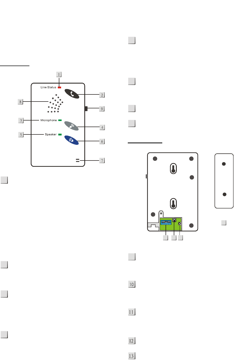
I. Identifying the parts
TOP VIEW
ANSWER LED (DUAL COLOUR GREEN +
RED LED)
— Power Indicator; ANSWER LED light ON
in GREEN when Power is ON and system
is in Stand-By Mode.
— ANSWER LED flashes in GREEN and
RED alternately when CTC-808 detects a
line fault (e.g. Phone-Line is not
connected)
— ANSWER LED light ON in RED when
CTC-808 is in service during a phone
conversation.
ANSWER BUTTON
— Press once to answer the incoming call.
— Press again to terminate the call.
MICROPHONE LED
— Microphone Active Mode Indicator; the
LED light ON in GREEN when the
microphone is active.
— The LED dims when microphone is OFF.
MICROPHONE BUTTON
— Press once to activate the Microphone.
— Press again to deactivate the
Microphone.
SPEAKER LED
— Speaker Active Mode Indicator; the LED
light ON in GREEN when the speaker is
active.
— The LED dims when speaker is OFF.
SPEAKER BUTTON
— Press once to activate the Speaker.
— Press again to deactivate the Speaker.
MICROPHONE
SPEAKER
REAR VIEW
SPEAKER VOLUME CONTROL
— Slide upward for louder volume; Slide
downward for lower volume. .
PHONE LINE JACK
— This jack is for the connection to the
Telephone unit
DC JACK
— For connecting the DC 12V 500mA power
adaptor
FUNCTION SETTING DIP SWITCH
WALL MOUNTING BRACKET
1
4
6
5
7
8
2
11
10
13
12
06-Oct-2011
2
II. The Power Supply
CTC-808 is powered by an AC switching power
adaptor connecting to a wall outlet. Be sure to only
use an adaptor with the appropriate AC voltage
rating to prevent component damage. The power
adaptor specification is INPUT: 100-240VAC
50/60Hz, Output: 12V 0.5A 6W MAX.
z AC Adaptor Application:
An Adaptor is supplied with CTC-808 and
ready to be connected to the wall outlet when
shipped.
z At the back of CTC-808, locate the DC
Jack and connect to the Adaptor.
z Plug the AC Adaptor pinhead to a wall
outlet.
z Once the power is applied, CTC-808 will
emit 2 short beeps with the following LED
performance:
If the telephone line is NOT
connected to CTC-808:
ANSWER LED flashes in GREEN
and RED alternately to indicate that
the telephone line is not properly
connected.
MICROPHONE & SPEAKER LED
light ON in GREEN for one sec and
then dims.
If the telephone line is connected
to CTC-808:
ANSWER LED turns permanently ON
in GREEN.
MICROPHONE & SPEAKER LED
light ON in GREEN for one sec and
then dims.
System is now in Stand-By Mode with
MICROPHONE & SPEAKER LED act
as they are previously set up.
z Rechargeable Battery:
z In addition to the adaptor, there is a
rechargeable battery inside the device that
serves as a back up in case of a power
failure.
z The battery used is a 6 x 600 mAH Ni-mH
rechargeable battery pack.
z During normal operation, the AC power
adaptor is used to supply power to
CTC-808 and at the same time recharge
the battery.
z When the battery is fully charged, it can
provide back-up power for a period of at
least 15 hours. It takes approximately 48
hours to fully charge the battery.
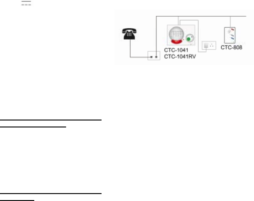
III. Installing CTC-808
CTC-808 is designed to work in pair with a regular
phone unit, any GARDSMAN Security Alarm Panels,
or GARDSMAN Social Alarm Panels.
z Locate the wall outlet phone jack that shares
the same line circuit for both CTC-808 and its
paired product.
z Plug one end of the telephone cable into the
wall outlet and the other to CTC-808.
z Use the two-hole Wall Mounting Bracket as a
template, and mark off the holes’ positions.
z Drill two holes and fix the screws & plugs
provided.
z Hook the CTC-808 unit onto the Wall Mounting
Bracket (holding the unit with the front facing
you.

3
Configuring CTC-808
I. Microphone Sensitivity
Adjusting SW #1 - SW #4 by sliding the Dip Switch
Upwards / Downwards to choose the sensitivity
level of Microphone.
z Among the 4 switches, only one Switch must
be slid to ON position.
z Sliding SW1 up (ON position) while SW2 -
SW4 remains down (OFF position), the
microphone becomes the most sensitive with
furthest range.
z Conversely, sliding SW4 up (ON position)
while SW1 - SW3 remains down (OFF
position), the microphone becomes the least
sensitive with shortest range.
II. Ringer On/Off
CTC-808 can be programmed to have the ringer
sounded or silenced when there is an incoming call.
Adjust SW #5 of the Dip Switch as shown below:
SW5 RINGER
OFF SILENCE
ON ENABLE
III. Warning Sound On/Off
CTC-808 can be programmed to emit 2 short
warning beeps or to be silenced when the Handset
hangs-up. Adjust SW #6 of the Dip Switch Set as
shown below:
SW6 OFF-HOOK
BEEP
OFF SILENCE
ON ENABLE
<
<N
NO
OT
TE
E>
>
) When set as Enable, warning sounds are
indicated as below:
z Power On: Beep x 2
z On Hook: Beep x 2
z Hands Up (DTMF 9 command
received): Beep x 3
z Off Hook: Beep x 1
IV. Master Device Set Up
CTC-808 is designed to work in pair with a regular
phone unit, any GARDSMAN Security Alarm Panels,
or GARDSMAN Social Alarm Panels (Medical alarm
panel).
To set CTC-808 in pair use with a particular device,
adjust SW #7 and SW #8 as shown below:
1. With Regular Phone unit or Voice Reporting
Panel only:
SW7 SW8
OFF OFF
It is used to adjust CTC-808 to work in pair with
the following devices:
a. Regular phone set
b. Any Security or Social Alarm panel with
voice reporting only (i.e. no Monitoring
Center digital reporting is involved).
2. With digital Security alarm panel:
Only compatible with the Security Alarm
Panel via CID reporting
SW7 SW8
OFF ON
After an alarm message is successfully
acknowledged by the Monitoring Center,
CTC-808 will respond according to the setting
in the Panel.
3. With digital Social alarm panel (Medical
alarm panel):
Only compatible with the Social Alarm
Panel (Medical alarm panel) via CID
reporting and the Follow-On setting is set
as “Wait Command” (please refer to the
Panel manual)
SW7 SW8
ON OFF
After an alarm message is successfully
acknowledged by the Monitoring Center, the
Social alarm panel will wait the DTMF “1”, “2”
or “3” command from the Monitoring Center.
CTC-808 will follow the command with the
alarm panel.

4
DTMF “1” – opens Microphone only for
“Talk-Only Communication.
DTMF “2” – opens both Microphone &
Speaker for “Two-Way Voice”.
DTMF “3” – opens Speaker only for “Listen-In
Communication”
4. With digital Social alarm panel (Medical alarm
panel) :
Only compatible with the Social Alarm
Panel (Medical alarm panel) via CID
reporting and the Follow-On setting is set
as “Two-way voice communication” or
“Listen-in only” (please refer to the Panel
manual)
SW7 SW8
ON ON
After an alarm message is successfully
acknowledged by the Monitoring Center, the
Social alarm panel and CTC-808 enter either
“Two-Way Voice Communication” or “Listen-in
only”.
During the Two-Way Voice Communication” or
“Listen-in, Monitoring Center can still control
the alarm panel and CTC-808 remotely by
DTMF command “1”, “2” or “3”
DTMF “1” – opens Microphone only for
“Talk-Only Communication.
DTMF “2” – opens both Microphone &
Speaker for “Two-Way Voice”.
DTMF “3” – opens Speaker only for “Listen-In
Communication”
Operation
I. Incoming Calls
z Answered by Panel or Phone
CTC-808 activates when a call is
answered by Panel or Phone handset.
During the entire call, user is free to turn
ON/OFF the Microphone & Speaker by
pressing their respective buttons.
After the call is terminated, Microphone
and/or Speaker with their corresponding
LED’s return their stand-by status.
Microphone and/or Speaker can still be
freely controlled by remote command.
z Answered by CTC-808
Press ANSWER button, Answer LED
changes from GREEN to RED.
Both Microphone and Speaker turn ON,
both LED’s ON, regardless of their
stand-by status.
During the entire call, user is free to turn
ON/OFF the Microphone & Speaker by
pressing their respective buttons.
Terminate the call by pressing ANSWER
button at any time. Microphone, Speaker
and their corresponding LED’s will return
to their stand-by status settings.
II. Outgoing Calls
z When paired with digital Security or Social
panels
CTC-808 is unable to make any outgoing
call.
Press the Red (help) button on the Social
Alarm Panel to make an outgoing code.
After an alarm message is successfully
acknowledged by the Monitoring Center,
communication will be setup
automatically among the Medical Panel,
Monitoring Center and CTC-808.
z When paired with regular phone unit
Once the first number is entered within
10-second after the handset has been
picked up, Microphone & Speaker will
automatically operate according to their
stand-by status five seconds after the last
key pressing.
If the first number entering exceeds the
10-second time limit, user will have to
turn ON/OFF the Microphone & Speaker
manually.
During the entire call, user is free to turn
5
ON/OFF the Microphone & Speaker by
pressing their respective buttons.
After the call is terminated, Microphone
and/or Speaker with their corresponding
LED’s return to their stand-by status.
III. Fault Detection
To enable CTC-808 to detect low battery, battery
disconnection or AC failure conditions, it has to be
learnt into the Social Alarm Panel (Medical Alarm
Panel) first. The learning process is listed as below:
a. Press both the Answer and Speaker buttons for
3 seconds and release both buttons until you
hear a long beep. Then CTC-808 will transmit a
learn code.
b. If the Medical Alarm Panels successfully
receives a learn code from CTC-808, CTC-808
is able to transmit a signal of low battery, battery
disconnection or AC failure to the Control Panel
after detecting those faults.
z Low Battery
- 30 seconds after CTC-808 detects the low battery
condition, it will transmit a signal of low battery to
the Medical Alarm Panel for notification.
- 30 seconds after CTC-808 detects the battery
restore, it will transmit a signal to the Medical
Alarm Panel for notification.
z Battery Disconnection
CTC-808 can detect the absence of battery in the
following cases:
Battery not connected
Battery failure.
- 30 seconds after CTC-808 detects the battery
disconnection, it will transmit a signal of battery
disconnection to the Medical Alarm Panel for
notification.
- 30 seconds after CTC-808 detects the battery
connection, it will transmit a restore signal to the
Medical Alarm Panel for notification.
z AC Failure Detection
- 30 seconds after CTC-808 detects the AC failure
fault, it will transmit a signal of AC failure to the
Medical Alarm Panel for notification.
- 10 seconds after the AC Power resumes, it will
transmit an AC power resume signal to the Medical
Alarm Panel for notification.
This device complies with Part 15 of the FCC Rules.
Operation is subject to the following two conditions:
(1) this device may not cause harmful interference,
and
(2) this device must accept any interference
received, including interference that may cause
undesired operation.
Federal Communication Commission Interference Statement
This equipment has been tested and found to comply with the limits for a Class B
digital device, pursuant to Part 15 of the FCC Rules. These limits are designed to
provide reasonable protection against harmful interference in a residential installation.
This equipment generates, uses and can radiate radio frequency energy and, if not
installed and used in accordance with the instructions, may cause harmful interference
to radio communications. However, there is no guarantee that interference will not
occur in a particular installation. If this equipment does cause harmful interference to
radio or television reception, which can be determined by turning the equipment off
and on, the user is encouraged to try to correct the interference by one of the
following measures:
. Reorient or relocate the receiving antenna.
. Increase the separation between the equipment and receiver.
. Connect the equipment into an outlet on a circuit different from that to which the
receiver is connected.
. Consult the dealer or an experienced radio/TV technician for help.
FCC Caution: To assure continued compliance, any changes or modifications not
expressly approved by the party responsible for compliance could void the user's
authority to operate this equipment. (Example - use only shielded interface cables
when connecting to computer or peripheral devices).