Climax Technology Co DC16 Door Contact User Manual DC 16SL F1 Abode 20150723
Climax Technology Co Ltd Door Contact DC 16SL F1 Abode 20150723
Users Manual
Door Contact (DC-16SL-F1) User Manual
The Door Contact monitors the opening/closing of specified devices (e.g. door or window). The Door Contact is fixed to the
monitored device frame with an actuating magnet fixed to the device. When the door or window opens, the magnet moves
away from the Door Contact, activating an internal magnetic switch causing the Door Contact to transmit alarm signal to the
Control Panel. The device also has the capabilities of communicating signal problems along with low battery situations.
The Door Contact design is consisted of a cover and base. The cover contains all electronics and the base provides a
means for fixing the device.
z
z
I
Id
de
en
nt
ti
if
fy
yi
in
ng
g
t
th
he
e
p
pa
ar
rt
ts
s
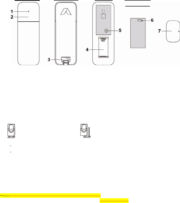
1. LED Indicator
2. Learn / Test Button (Top Cover)
- Press the Top Cover to transmit a learn code and enter Test Mode for 3 minutes
3. Battery Insulator
4. Battery
5. PCB Board Fixing Screw
- Release the screw to flip over PCB board and access Supervision Jumper if needed.
6. Supervision Jumper Switch (JP2)
- When the jumper is set as ON, the Supervision is disabled.
- When the jumper is set as OFF, the Supervision is enabled.(Factory default)
7. Magnet
- Mount the magnet on the left side of the Door Contact The Door Contact should be installed either upright or
inverted to ensure that the rib-marked side faces the magnet.
z
z
L
LE
ED
D
I
In
nd
di
ic
ca
at
to
or
r
In Normal operation mode, the LED indicator remains off except in the following situations:
z When the Door Contact’s tamper switch is triggered.
z Every time when the Door Contact is activated with either Tamper or Low battery condition.
z Every time when the Door Contact is activated and transmitting the signal under the Test mode.
z
z
S
Su
up
pe
er
rv
vi
is
si
io
on
n
z Enable or Disable the Supervision function using JP2 jumper.
z When enabled, the Door Contact will automatically transmit Supervisory signals periodically to the Control
Panel at random intervals of 30 to 50 minutes.
If the Control Panel has not received the signal from the Door Contact for a preset period time, the Control
Panel will indicate that particular Door Contact is experiencing an out-of-signal problem.
z
z
B
Ba
at
tt
te
er
ry
y
The Door Contact uses one 3V CR2 Lithium battery as its power source, it is also capable of detecting low battery.
When the battery is low, a low battery signal will be sent to the Control Panel along with regular transmission. The
LED will light up when the Door Contact is activated under low battery status. When battery is exhausted, the Door
Contact will stop all function and the LED will flash every 4 seconds.
Jumper On
The jumper link is inserted
Jumper Off
if the jumper link is removed or “parked” on one pin.
Front View Back View Internal PCB Board
Back View
z Changing Battery:
After the battery has been removed, press the Learn / Test button several times to fully discharge before
inserting the new battery.
z
z
T
Te
es
st
t
M
Mo
od
de
e
The Door Contact can be put into Test mode for 3 minutes by pressing the Test Button on the front cover once.
During Test mode, the LED indicator will turn on upon triggering. Each press on the Test Button, the Door Contact
will transmit a test signal to the Control Panel for radio range test and resets the test mode back to the 3-minute
duration. It will exit Test Mode automatically after the 3 minutes and returns to Normal Operation mode.
z
z
G
Ge
et
tt
ti
in
ng
g
S
St
ta
ar
rt
te
ed
d
Step 1: Pull out the battery Insulator.
Step 2: Put the Control Panel into learning mode, refer to Control Panel manual for detail.
Step 3: Press the Test Button on Door Contact to send signal to the Control Panel.
Step 4: If the Control Panel successfully receives the signal, the Control Panel should respond (e.g. emitting
beeps). Refer to your Control Panel manual to complete the learning process.
Step 5: After the Door Contact is learnt-in, put the Control Panel into “Walk Test” mode, hold the Door Contact at
the desired location, and press the Test button to confirm if this location is within signal range of the
Control Panel.
Step 6: When you are satisfied with the Door Contact at the chosen location, proceed to installation.
z
z
I
In
ns
st
ta
al
ll
la
at
ti
io
on
n
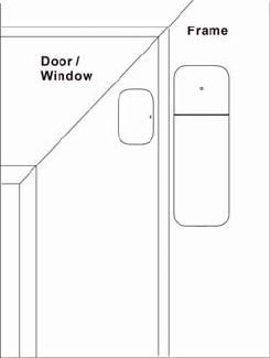
The Door Contact should be mounted using the self-adhesive tape provided.
I. Clean the surface with a suitable degreaser. If the surface paint is
peeling or cracked, clean the surface thoroughly.
II. Remove the protective covering from the one side of the
double-sided adhesive pad and firmly apply to the back of the
device.
III. Remove the other cover and firmly press the Door Contact onto
the door or window frame.
IV. Use another adhesive pad to mount the magnet on the door or
window. The magnet should be no more than 15mm from the
Door Contact when the door is closed.
V. Test the Door Contact function by opening and closing the door.
Check the Control Panel to make sure the Door Contact can
detect opening and closing properly. Move the magnet closer if
the Door Contact cannot detect normally.
This device complies with Part 15 of the FCC Rules. Operation is subject to the following two conditions:
(1) This device may not cause harmful interference, and
(2) This device must accept any interference received, including interference that may cause undesired operation.