Climax Technology Co DC23 Door Contact User Manual DC 23 DC 23 R3 20170217x
Climax Technology Co Ltd Door Contact DC 23 DC 23 R3 20170217x
Users Manual
1
Door Contact (DC-23 / DC-23-R3) User Manual
The Door Contact monitors the opening/closing of specified devices (e.g. door or window). The Door Contact is fixed to the
monitored device frame with an actuating magnet fixed to the device. When the door or window opens, the magnet moves away
from the Door Contact, activating an internal magnetic switch causing the Door Contact to transmit alarm signal to the Central
Panel. The device also has the capabilities of communicating signal problems along with low battery situations.
The Door Contact design consists of a cover and base. The cover contains all electronics and the base provides a means for
fixing the device. An enclosed PCB tamper switch provides tamper protection against unauthorized device opening and/or
removal.
DC-23 Series Door Contact includes following models:
DC-23: Door Contact cover is secured by a bottom fixing screw.
DC-23-R3: Door Contact cover is secured by two latches at top and bottom
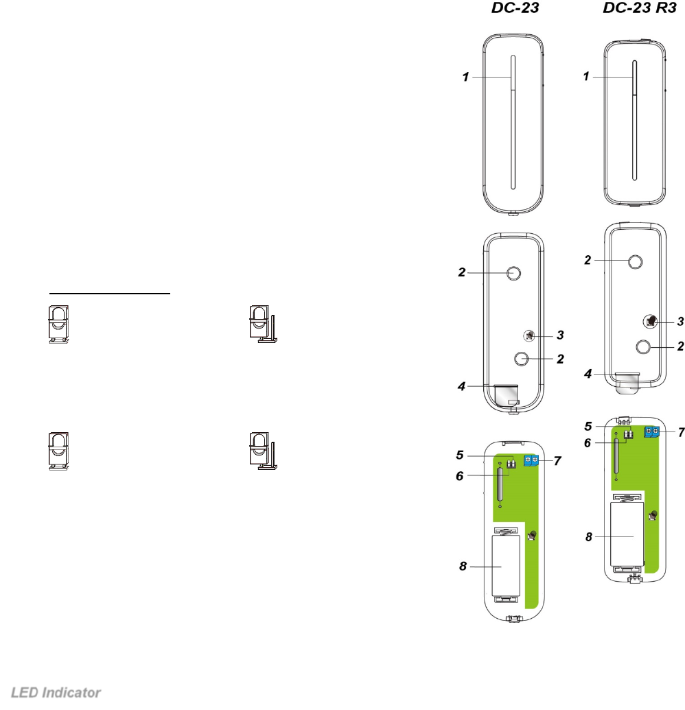
Parts Identification
1. LED indicator / Test button
Press the Test button to transmit learning code or enter test mode
for 3 min.
2. Mounting Holes
Used to fixed and screw the Door Contact directly onto the Door
Frame or Wall.
3. Tamper Switch
When Door Contact is mounted, the Tamper switch will be
activated when the cover is opened or when the Door Contact is
removed from mounted surface.
4. Battery Insulator
5. Supervision Jumper Switch (JP2)
(868WF model only)
- Jumper ON: Supervision disabled
- Jumper OFF: Supervision enabled. (Factory Default)
6. Reed Switch Jumper Switch (JP3)
- Jumper ON: Reed Switch disabled. Only the device connected to
Extension Terminal will activate the Door Contact
- Jumper OFF: Reed Switch enabled. (Factory Default for all models)
7. Extension Terminal
In addition to the built-in magnet switch, an additional 2-pin dry contact
terminal is provided for an extension magnet switch or any device with
N.C. (Normally Closed) functionality.
8. Battery Compartment
Features
LED Indicator
In Normal Operation Mode, the LED will not light when the Door Contact is activated.
When the Door Contact battery voltage is low, every time the Door Contact is activated (device opened/ closed), the
LED will light on for 2 sec.
When the cover is opened or the tamper switch is triggered, the LED will light on for 2 seconds. When a tamper
condition persists, the LED will light on for 2 seconds whenever the Door Contact Is activated.
When the Door Contact is in Test mode, the LED will light up every time it is activated.
Jumper On
The jumper link is inserted,
connecting the two pins
Jumper Off
if the jumper link is removed or
“parked” on one pin.
Jumper On
The jumper link is inserted,
connecting the two pins
Jumper Off
if the jumper link is removed or
“parked” on one pin.
2
When the battery is exhausted, the Door Contact will stop all function, the LED will flash every 4 seconds.
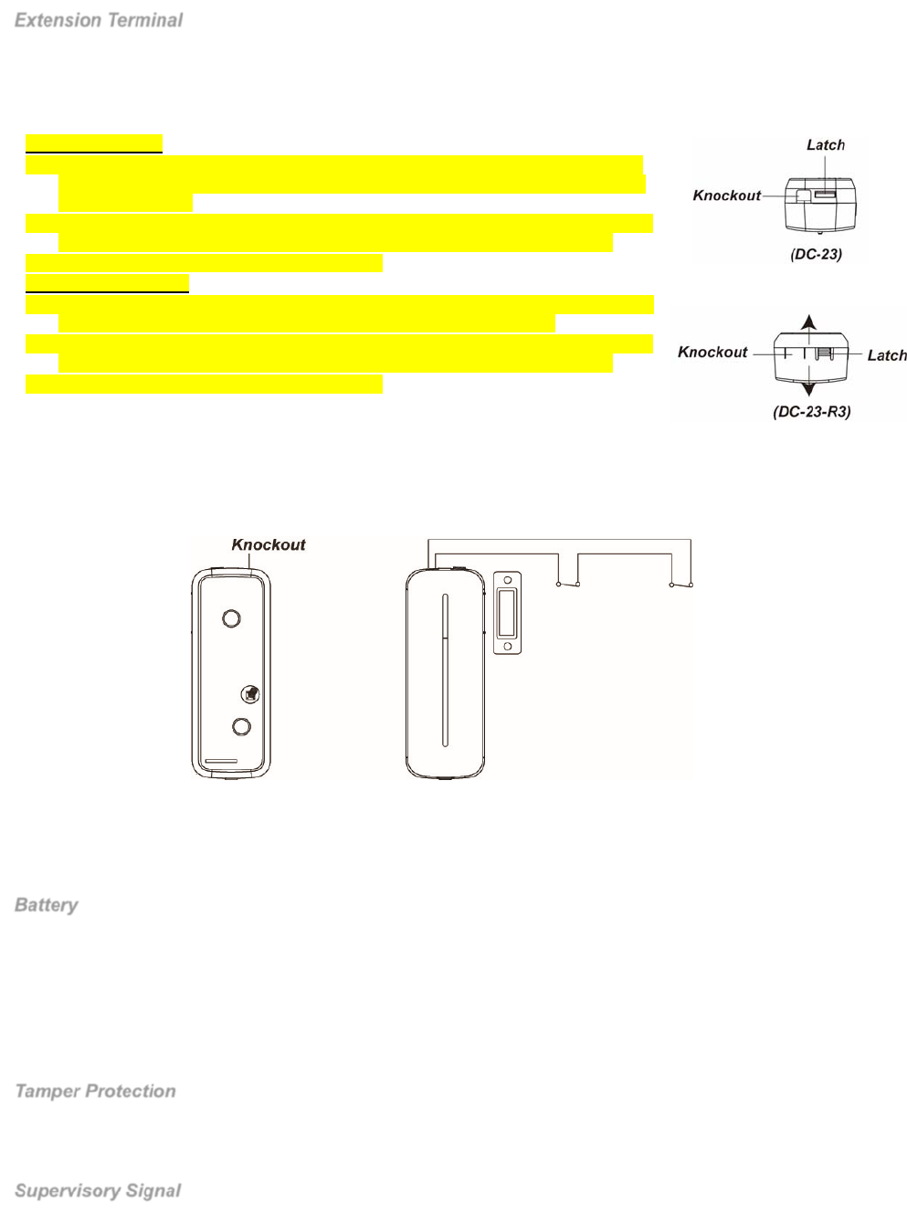
Extension Terminal
The Door Contact has an extension terminal to provide enhanced flexibility. The extension terminal forms a closed loop
with the device connected to it. When the device is triggered the loop is opened, the Door Contact will also be triggered.
The extension terminal and the internal magnetic switch can function together to trigger the Door Contact when either of
them is activated, you can also choose to disable the internal magnetic switch through JP3 Jumper setting.
To connect the device to extension terminal:
For DC-23 model:
1. Open the Door Contact’s cover by using a screwdriver to loosen the cover fixing
screw at the buttom of the Door Contact’s cover. (See picture below picture from
upper view angle).
2. The upper end of the front case has a thinner plastic knockout. Break through the
knockout to create a hole for the wiring connection to the extension terminal.
3. Connect the device to the extension terminal
For DC-23-R3 model:
4. Use your thumb to press on the Latch, while pressing it, pull out the cover from the
base of the Door Contact (see below picture from upper view angle).
5. The upper end of the front case has a thinner plastic knockout. Break through the
knockout to create a hole for the wiring connection to the extension terminal.
6. Connect the device to the extension terminal
The Extension terminal may be useful for the following situation.
If the Door Contact cannot be mounted on the door frame, you can connect an
additional extension magnet switch to the extension terminal to mount the Door Contact remotely.
Any dry contact device with N.C. (Normal Close) loop can be connected to the Extension Terminal making the Door
Contact serve as an Universal Transmitter.
Multiple dry contact device can be wired together with Door Contact, as show in diagram below.
The extension terminal and internal magnetic switch can function together to trigger the Door Contact when either of
them is activated, you can also choose to disable the internal magnetic switch through JP3 Jumper setting. If both
extension terminal and internal magnetic switch is in use and any of them is triggered (opened). The Door Contact will
only send Door Contact close (restore) signal when both of them are closed.
Battery
The Door Contact is powered by one CR123 3V Lithium battery. Please note: ALWAYS replace battery with the correct
size and voltage.
The Door Contact can detect low battery condition. When the battery voltage is low, a low battery signal will be sent to
the Control Panel to notify the condition. The LED will light up when the Door Contact is activated under low battery
status. When the battery is exhausted, the Door Contact will stop all function, the LED will flash every 4 seconds.
When changing battery, after removing the old batteries, press the Tamper Switch twice to fully discharge before
inserting new battery.
Tamper Protection
The Door Contact is protected by a tamper switch which is compressed against the mounting surface when the Door
Contact is mounted. Whenever the Door Contact cover is opened, or removed from mounted surface, the tamper
switch will be activated and the Door Contact will send a tamper open signal to remind the user of the condition.
Supervisory Signal
Supervision function for 868WF model is controlled by JP2 jumper setting. For non-868WF model, supervision
function is always enabled.
When enabled, the Door Contact will automatically transmit Supervisory Signals periodically to the Control Panel at
random intervals of 30-50 minutes.
3
If the Control Panel has not received the signal from the Door Contact for a preset period time, the Control Panel will
indicate the particular Door Contact is experiencing an out-of-signal problem.
Test Mode
Under Normal Mode, press the Test Button to transmit a test signal and learning code to the Control Panel. The Door
Contact will also enter the Test Mode for 3 minutes.
Under Test Mode, the LED will light up whenever the Door Contact is activated.
Each additional Test Button press will reset Test Mode time to 3 minutes.
Getting Started
Open the cover of the Door Contact and insert the battery.
Put the Control Panel into Learning Mode (please refer to panel operation manual).
Press the Door Contact test button.
Refer to your Control Panel operation manual to complete the learn-in process.
After the Door Contact is learned-in, place the Control Panel into (Walk Test) mode, hold the Door Contact in the
desired location, and press the Test button to transmit test signal to Control Panel. If the Control Panel is within Door
Contact signal range, the panel will display door contact information accordingly.
Proceed with mounting and installation once you are satisfied that the Door Contact location functions properly.
Installation
Installation Guideline
The Door Contact should be installed on the door/window frame, and the magnet on the door/window
The distance between the Door Contact and the magnet should be no more than 15mm when the door is closed.
Avoid mounting the Door Contact on metallic surface. If mounting on metallic surface, make sure to test whether the
Door Contact can be triggered when the door is opened.
Mount the Door Contact as high as possible.
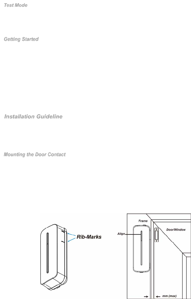
Mounting the Door Contact
1. Find a suitable location close to your door/window to install the Door Contact.
2. The Door Contact has 2 rib-marks on one side (refer to figure), marking the internal magnet switch location. The door
contact should be installed either upright or inverted to ensure that the rib-marked side faces the magnet.
3. To mount the Door Contact:
a) Use the 2 Door Contact mounting holes as a template for appropriate hole positioning.
b) Use the provided wall plugs for plaster/brick installation.
c) Screw the Door Contact into the provided wall plugs.
4. Fit the magnet on the door using the small piece of double sided adhesive tape or with provided screws. The magnet
must align with the rib-mark side of the Door Contact as shown in figure. Installation is now complete.
FCC Statement
4
This device complies with Part 15 of the FCC Rules. Operation is subject to the following two conditions:
(1) This device may not cause harmful interference, and
(2) This device must accept any interference received, including interference that may cause undesired operation.
FCC Caution:
To assure continued compliance, any changes or modifications not expressly approved by the party responsible for compliance may void
the user's authority to operate this equipment. (Example - use only shielded interface cables when connecting to computer or peripheral
devices).