Climax Technology Co DC9 Door Contact User Manual DC 9 315M for Alarmforce
Climax Technology Co Ltd Door Contact DC 9 315M for Alarmforce
UserManual.wiki
>
Climax Technology Co
>
DC9 User Manual
Users Manual
Navigation menu
Upload a User Manual
Namespaces
Wiki Guide
HTML
PDF
Info
Views
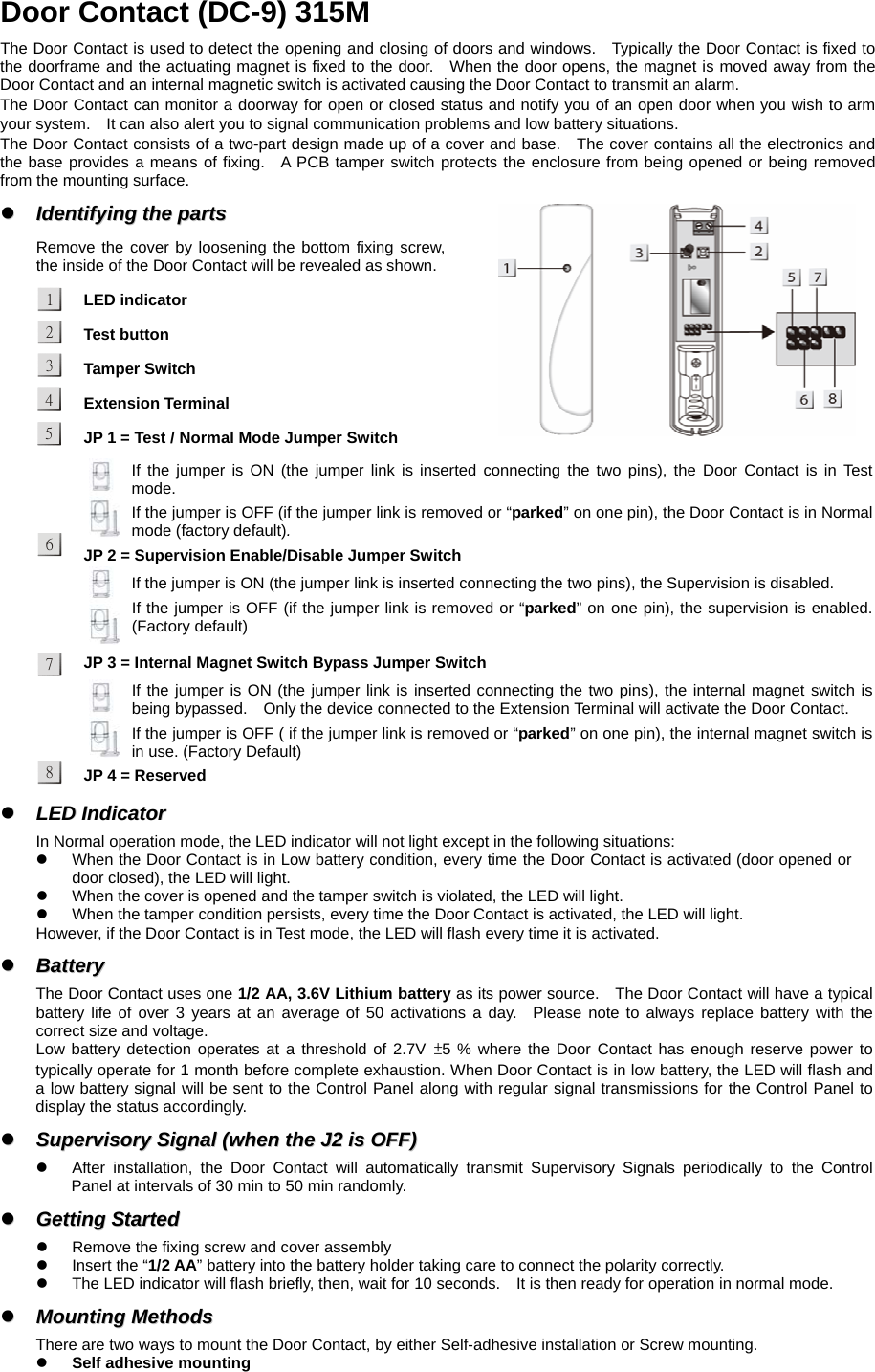
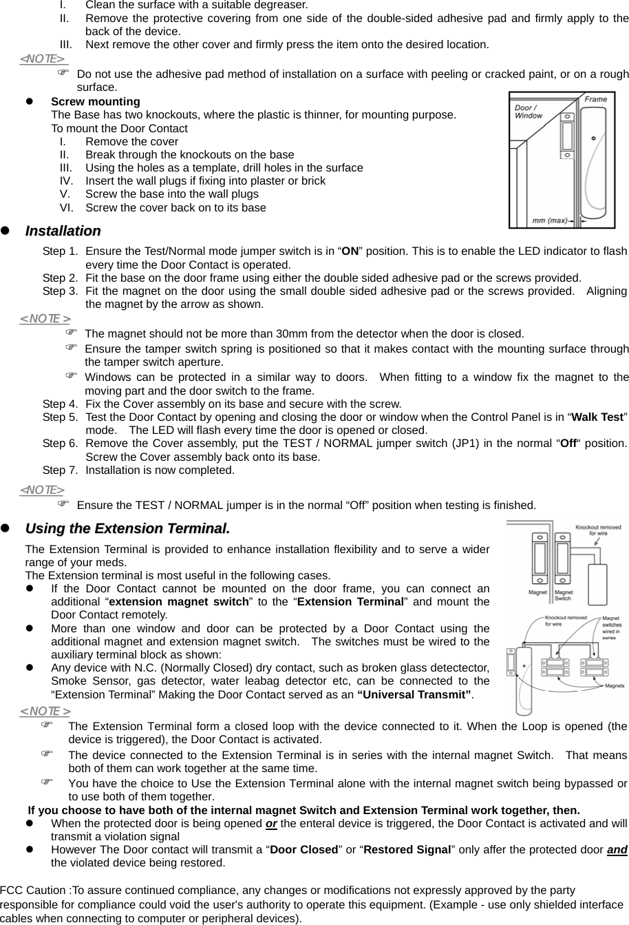
User Manual
Discussion / Help
Navigation