Climax Technology Co EMDZB Electricity Power Reader User Manual
Climax Technology Co Ltd Electricity Power Reader Users Manual
Users Manual
1
EMD-1ZBS Electricity Power Reader
Introduction
The Energy Meter is a ZigBee Electricity Power reader designed to be used with a digital watt hour meter
supporting LED pulse output port. The E-meter reads the LED pulse from the watt hour meter and transmits the
data to ZigBee network coordinator.
The Energy Meter utilizes ZigBee technology for wireless signal transmission. ZigBee is a wireless communication
protocol that is reliable, has low power consumption and has high transmission efficiency. Based on the
IEEE802.15.4 standard, ZigBee allows a large amount of devices to be included in a network and coordinated for
data exchange and signal transmission.
The Energy Meter serves as an end device in the ZigBee network. It can be included in the ZigBee network to
transmit signal upon activation, but cannot permit any other ZigBee device to join the network through the Energy
Meter.
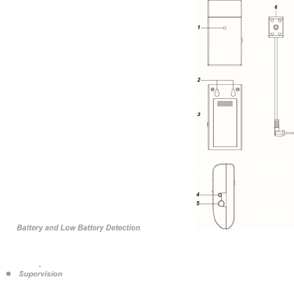
Parts Identification
1. LED indicator
The LED indicator lights up in the following conditions:
- Flashes quickly:
The Energy Meter received LED signal.
- Flashes once:
The Energy Meter is reset.
- Flashes twice:
The Energy Meter has successfully joined a ZigBee network.
- Flashes every 20 minutes
The Energy Meter has lost connection to current ZigBee network
2. Mounting Holes
3. Battery compartment Cover
Remove the cover to insert 2 Alkaline AA 1.5V batteries to power up the
Energy Meter.
4. LED Sensor Jack
Plug the Sensor into this jack to receive LED signal from the watt hour
meter.
5. Function Button
- Press the button once to transmit supervision signal.
- Press and hold the button for 10 seconds then release to reset the
Power Meter.
6. IR Sensor
Attach the IR sensor to the watt hour meter, and plug into the IR sensor
Jack to read data from the watt hour meter.
Features
Battery and Low Battery Detection
The Energy Meter uses 2 Alkaline 1.5V batteries as its power source, It feature Low Battery Detection
function. When the battery voltage is low, the Energy Meter will transmit Low Battery signal to notify ZigBee
network coordinator.
When changing battery, after removing the old batteries, press the function button a couple times to fully
discharge before inserting new batteries
Supervision
The Energy Meter will transmit a supervision signal to report its condition regularly according to user setting.
The factory default interval is 30 minutes. The user can also press the Function Button once to transmit a
supervision signal manually.
2
ZigBee Network Setup
ZigBee Device Guideline
ZigBee is a wireless communication protocol that is reliable, has low power consumption and has high
transmission efficiency. Based on the IEEE802.15.4 standard, ZigBee allows a large amount of devices to be
included in a network and are coordinated for data exchange and signal transmission.
Joining the ZigBee Network
As a ZigBee device, the Power Switch needs to join a ZigBee network to receive commands and transmit
energy consumption information. Follow the steps bellow to join the Power Switch into a ZigBee network.
The Energy Meter can only join ZigBee network within 3 minutes after power on.
1. Insert batteries to power on the E-meter.
2. Press and hold the function button for 10 seconds within 3 minutes after power on to reset E-meter and
start searching for existing ZigBee network. Please make sure the permit-to-join feature on the router or
coordinator of your ZigBee network is enabled.
3. If the E-meter successfully joins a ZigBee network, the LED Indicator will flash twice to confirm.
4. After joining the ZigBee network, the Power Switch will be registered in the network automatically. Please
check the Zigbee network coordinator, system control panel or CIE (Control and Indicating Equipment) to
confirm if joining and registration is successful.
5. If registration and joining to the network is unsuccessful, please check your ZigBee network coordinator,
system control panel or CIE setting to ensure the permit-to-join function is available, and then use the
Factory Reset function below to join the ZigBee network.
Removing Device from ZigBee Network (Factory Reset)
To remove the device from current ZigBee network, the Energy Meter must be put to Factory Reset to
complete device removal. Factory Reset function will clear the device of its stored setting information and
prompt Energy Meter to search for new ZigBee network.
Before removing device, make sure Energy Meter is within current ZigBee network signal range
1. Delete Energy Meter from current control panel / CIE.
2. The Energy Meter can only be reset within 3 minutes after power up. If it has been powered up for more
than 3 minutes, remove and reinsert the battery.
3. Press and hold the function button for 10 seconds, then release the button to reset Energy Meter.
4. Upon reset, the Energy Meter will clear current ZigBee network setting and transmit signal to ZigBee
coordinator to remove itself from current ZigBee network. It will then actively search for available ZigBee
network again and join the network automatically.
Operation
Installation
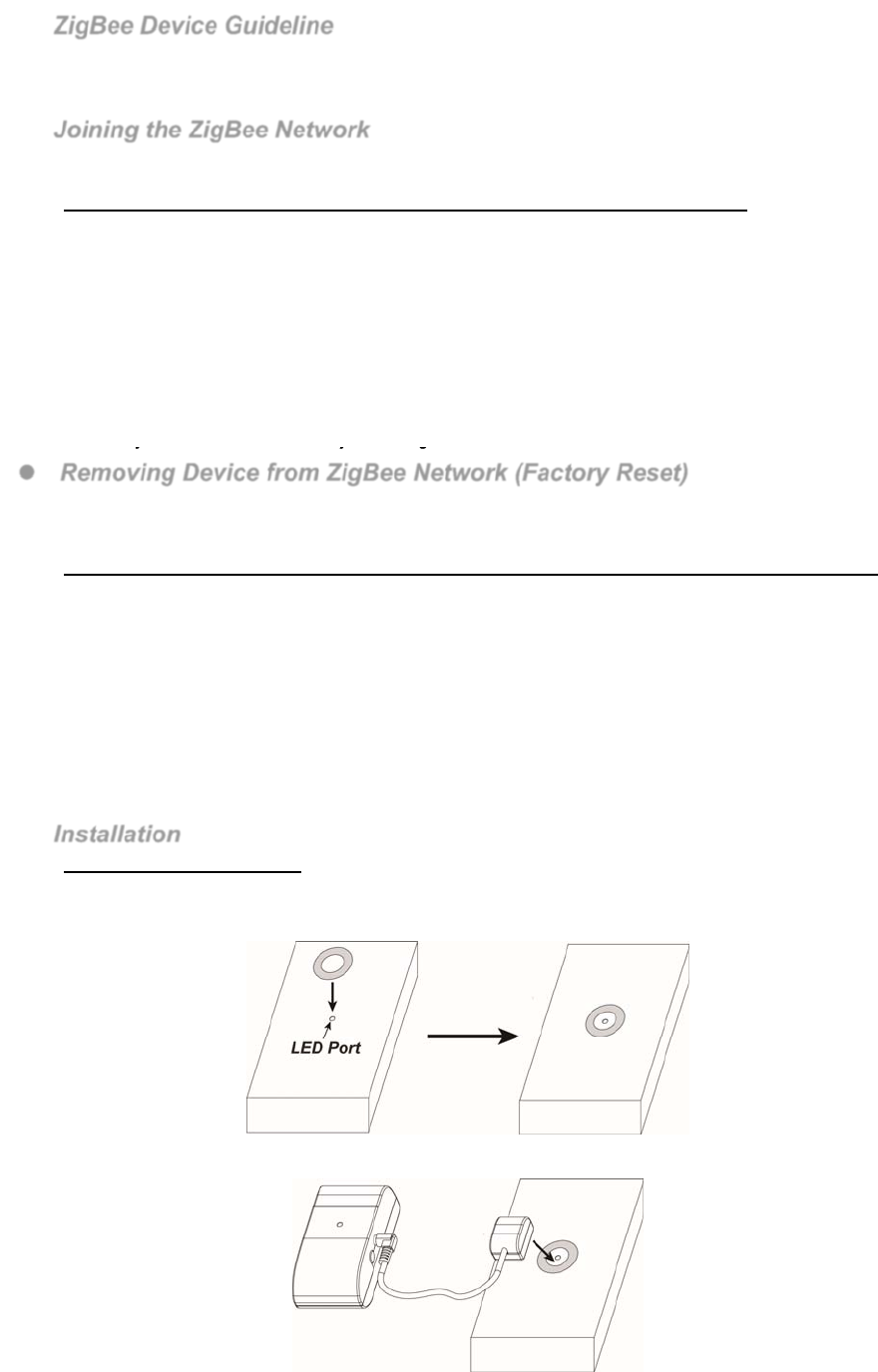
Wat Hour Meter connection.
A Washer with double-side adhesive tape is provided to connect the IR sensor to watt hour meter
1. Locate the LED pulse output port on the watt hour meter, remove the double-side adhesive tape cover on
the washer and apply the washer around the LED port.
2. The sensor head has built-in magnet. Apply the sensor head to the washer to attach the sensor to LED port
for reading LED pulse from watt hour meter
3
Wall Mounting
The Energy Meter has two mounting holes on the back for wall mounting.
1. Mark the mounting location on the wall according to mounting hole position
2. Install two screws at the mounting location.
3. Hook the Energy Meter onto the screws.
Energy Consumption Monitor
The Energy Meter reads LED pulse from the watt hour meter to monitor energy consumption.
The Energy Meter will transmit current wattage every 5 minutes to ZigBee network coordinator
The Energy Meter transmits a power data to coordinator whenever accumulated power usage increases
by 0.1kW/hr.
To clear the Energy Meter of its accumulated power consumption data, follow steps below:
1. Remove the batteries to power down.
2. Press and hold the function button and reinsert batteries again when holding down the button.
3. Keep holding the button and release after 3 seconds. The accumulated power consumption data
will be cleared.
Appendix (For developers only)
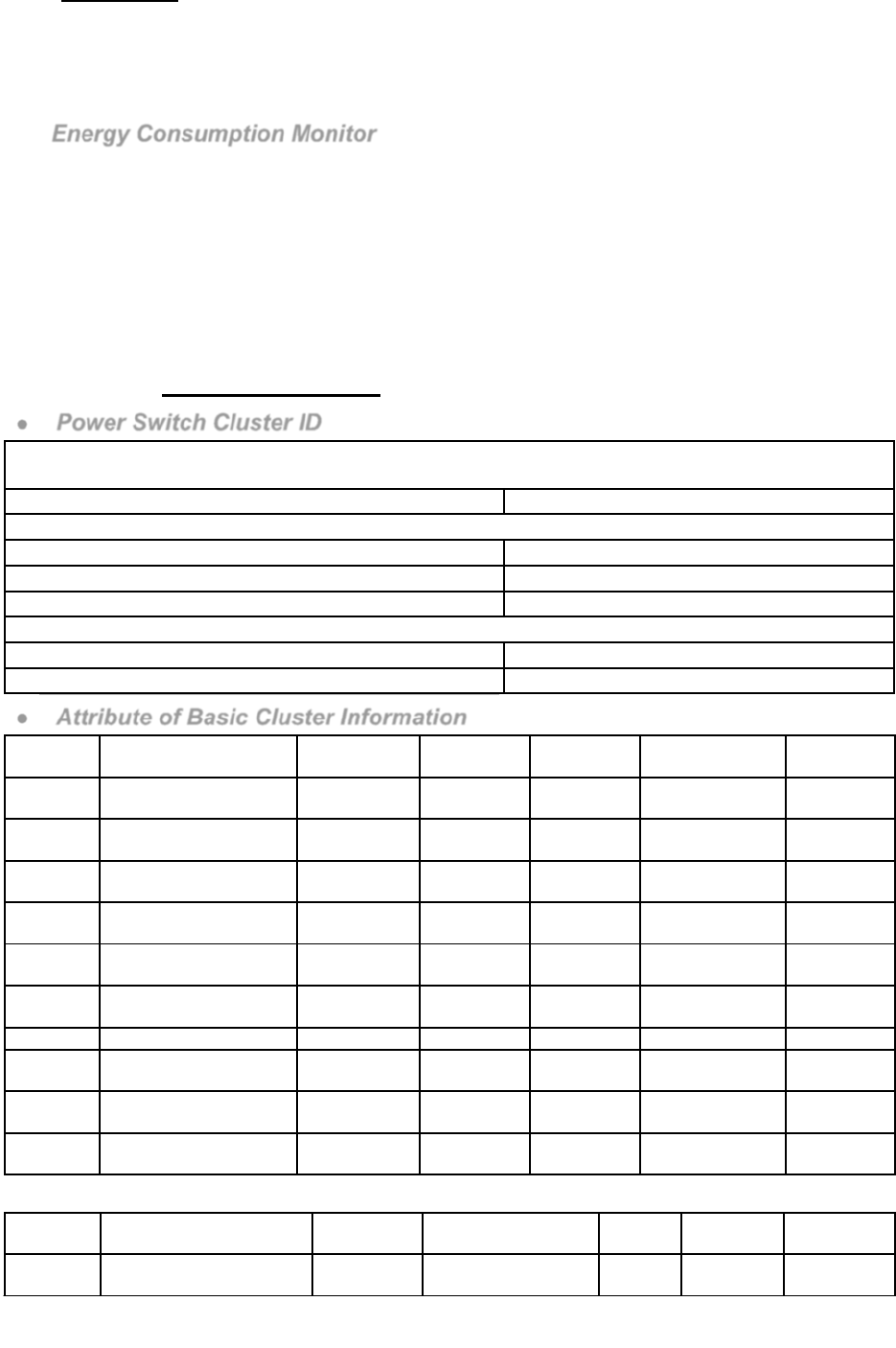
Power Switch Cluster ID
Device ID: Meter Interface : 0x0053
Endpoint:0x01
Server Side Client Side
Mandatory
Basic (0x0000) Identify(0x0003)
Metering(0x0702)
Meter Identification(0x0B01)
Optional
Power Configuration(0x0001) None
Identify(0x0003)
Attribute of Basic Cluster Information
Identifier Name Type Range Access Default Mandatory
/ Optional
0x0000 ZCLVersion Unsigned
8-bit integer 0x00 –0xff Read only 0x01 M
0x0001 ApplicationVersion Unsigned
8-bit integer 0x00 –0xff Read only 0x00 O
0x0003 HWVersion Unsigned
8-bit integer 0x00 –0xff Read only 0 O
0x0004 ManufacturerName Character
String
0 – 32
bytes Read only Climax
Technology O
0x0005 ModelIdentifier Character
String
0 – 32
bytes Read only (Model Version) O
0x0006 DateCode Character
String
0 – 16
bytes Read only O
0x0007 PowerSource 8-bit 0x00 –0xff Read only M
0x0010 LocationDescription Character
String
0 – 32
bytes
Read /
Write O
0x0011 PhysicalEnvironment 8-bit 0x00 –0xff Read /
Write 0x00 O
0x0012 DeviceEnabled Boolean 0x00 –0x01 Read /
Write 0x01 M
Attribute of Power Configuration Cluster Information
Identifier Name Type Range Access Default Mandatory
/ Optional
0x0035 BatteryAlarmMask 8-bit
bitmap 0000 000x Read /
Write 0000 0000 O
4
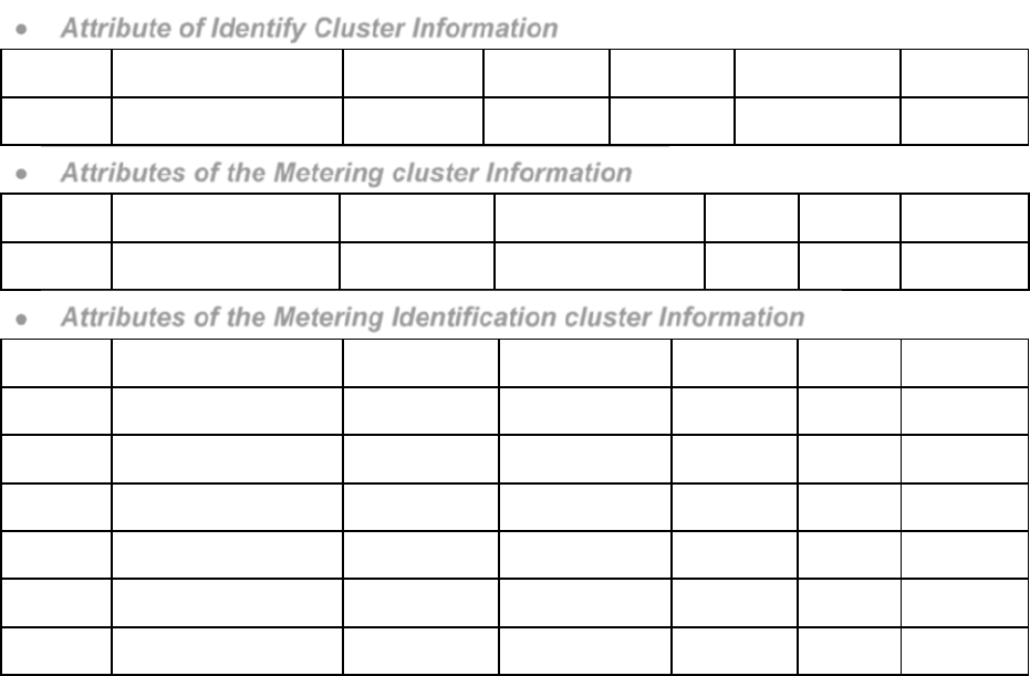
Attribute of Identify Cluster Information
Identifier Name Type Range Access Default Mandatory
/ Optional
0x0000 IdentifyTime Unsigned
16-bit integer 0x00 –0xffff Read /
Write 0x0000 M
Attributes of the Metering cluster Information
Identifier Name Type Range Access Default Mandatory
/ Optional
0x0000 CurrentSummation
Delivered
Unsigned
48-bit Integer
0x000000000000 to
0xFFFFFFFFFFFF
Read
Only M
Attributes of the Metering Identification cluster Information
Identifier Name Type Range Access Default Mandatory
/ Optional
0x0000 CompanyName Character
String 0 – 16 Octets Read Only - M
0x0001 MeterTypeID Unsigned
16-bit Integer
0x0000 to
0xFFFF Read Only - M
0x0004 DataQualityID Unsigned
16-bit Integer
0x0000 to
0xFFFF Read Only - M
0x000C POD Character
String 0 – 16 Octets Read Only - M
0x000D AvailablePower signed 24-bit
Integer
0x000000 to
0xFFFFFF Read Only - M
0x000E PowerThreshold signed 24-bit
Integer
0x000000 to
0xFFFFFF Read Only - M
5
Federal Communication Commission Interference Statement
This equipment has been tested and found to comply with the limits for a Class
B digital device, pursuant to Part 15 of the FCC Rules. These limits are
designed to provide reasonable protection against harmful interference in a
residential installation.
This equipment generates, uses and can radiate radio frequency energy and, if
not installed and used in accordance with the instructions, may cause harmful
interference to radio communications. However, there is no guarantee that
interference will not occur in a particular installation. If this equipment does
cause harmful interference to radio or television reception, which can be
determined by turning the equipment off and on, the user is encouraged to try
to correct the interference by one of the following measures:
. Reorient or relocate the receiving antenna.
. Increase the separation between the equipment and receiver.
. Connect the equipment into an outlet on a circuit different from that to which
the receiver is connected.
. Consult the dealer or an experienced radio/TV technician for help.
FCC Caution
: To assure continued compliance, any changes or modifications
not expressly approved by the party responsible for compliance could void the
user's authority to operate this equipment. (Example - use only shielded
interface cables when connecting to computer or peripheral devices).
FCC Radiation Exposure Statement
This equipment complies with FCC RF radiation exposure limits set forth for an
uncontrolled environment. This equipment should be installed and operated
with a minimum distance of 20 centimeters between the radiator and your
body.
This transmitter must not be co-located or operating in conjunction with any
other antenna or transmitter.
The antennas used for this transmitter must be installed to provide a
separation distance of at 20 cm from all persons and must not be co-located
or operating in conjunction with any other antenna or transmitter. This device
complies with Part 15 of the FCC Rules. Operation is subject to the following
two conditions:
(1) This device may not cause harmful interference, and
(2) This device must accept any interference received, including interference
that may cause undesired operation.