Climax Technology Co HDZW Heat Detector User Manual HD 9ZW 20151113 FCC
Climax Technology Co Ltd Heat Detector HD 9ZW 20151113 FCC
UserManual.wiki
>
Climax Technology Co
>
HDZW User Manual
Users Manual
Navigation menu
Upload a User Manual
Namespaces
Wiki Guide
HTML
PDF
Info
Views
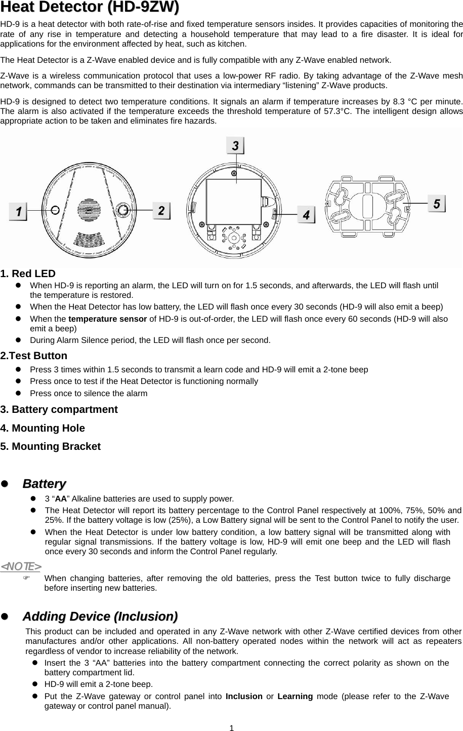
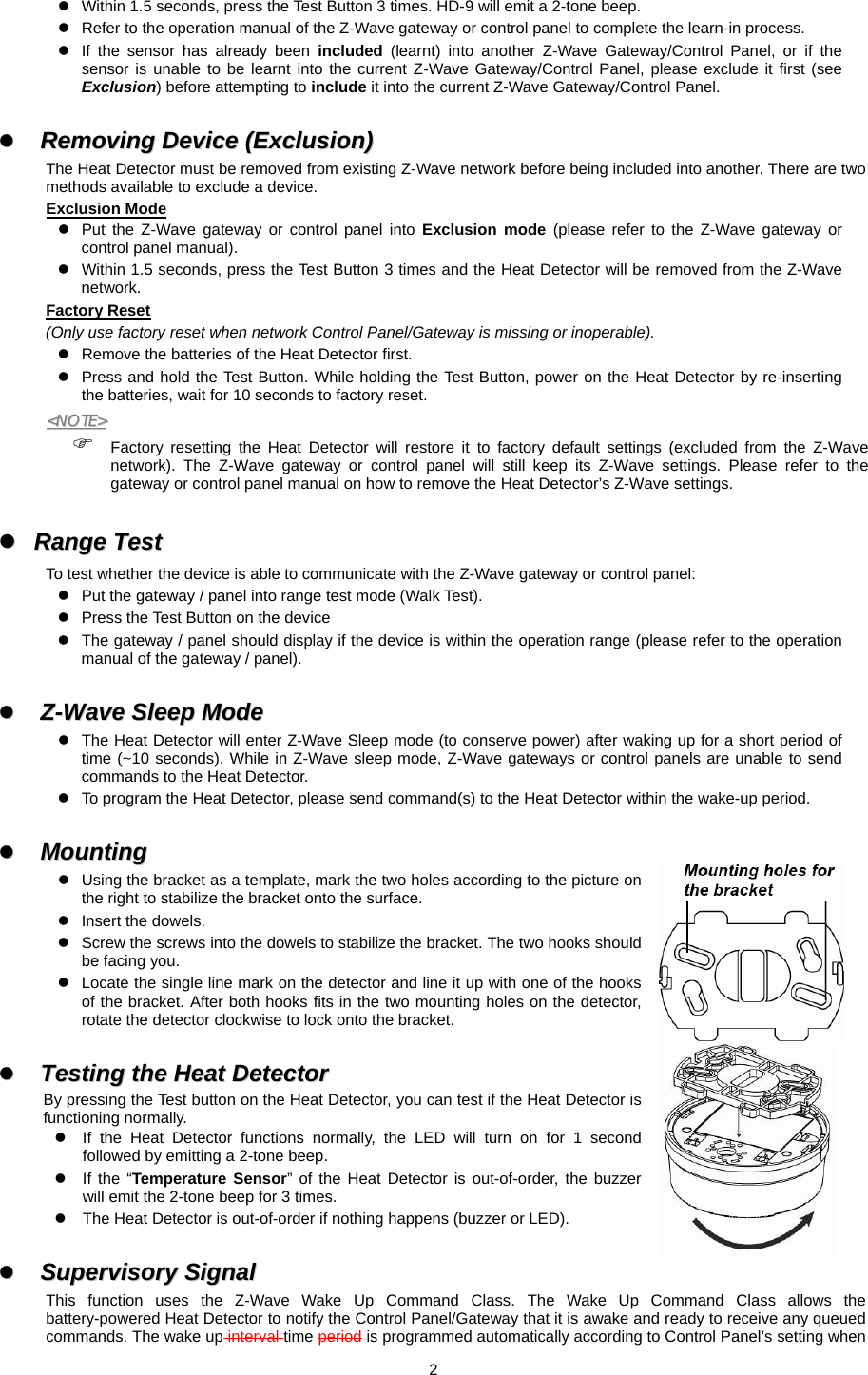
User Manual
Discussion / Help
Navigation