Climax Technology Co HSGW3G Smart Home Alarm Systems User Manual HSGW MANUAL module FCCx
Climax Technology Co Ltd Smart Home Alarm Systems HSGW MANUAL module FCCx
UserManual.wiki
>
Climax Technology Co
>
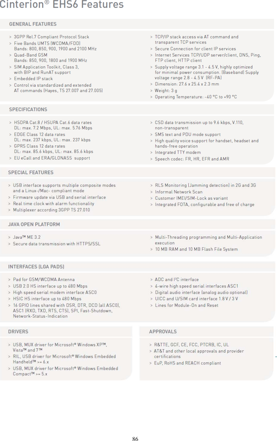
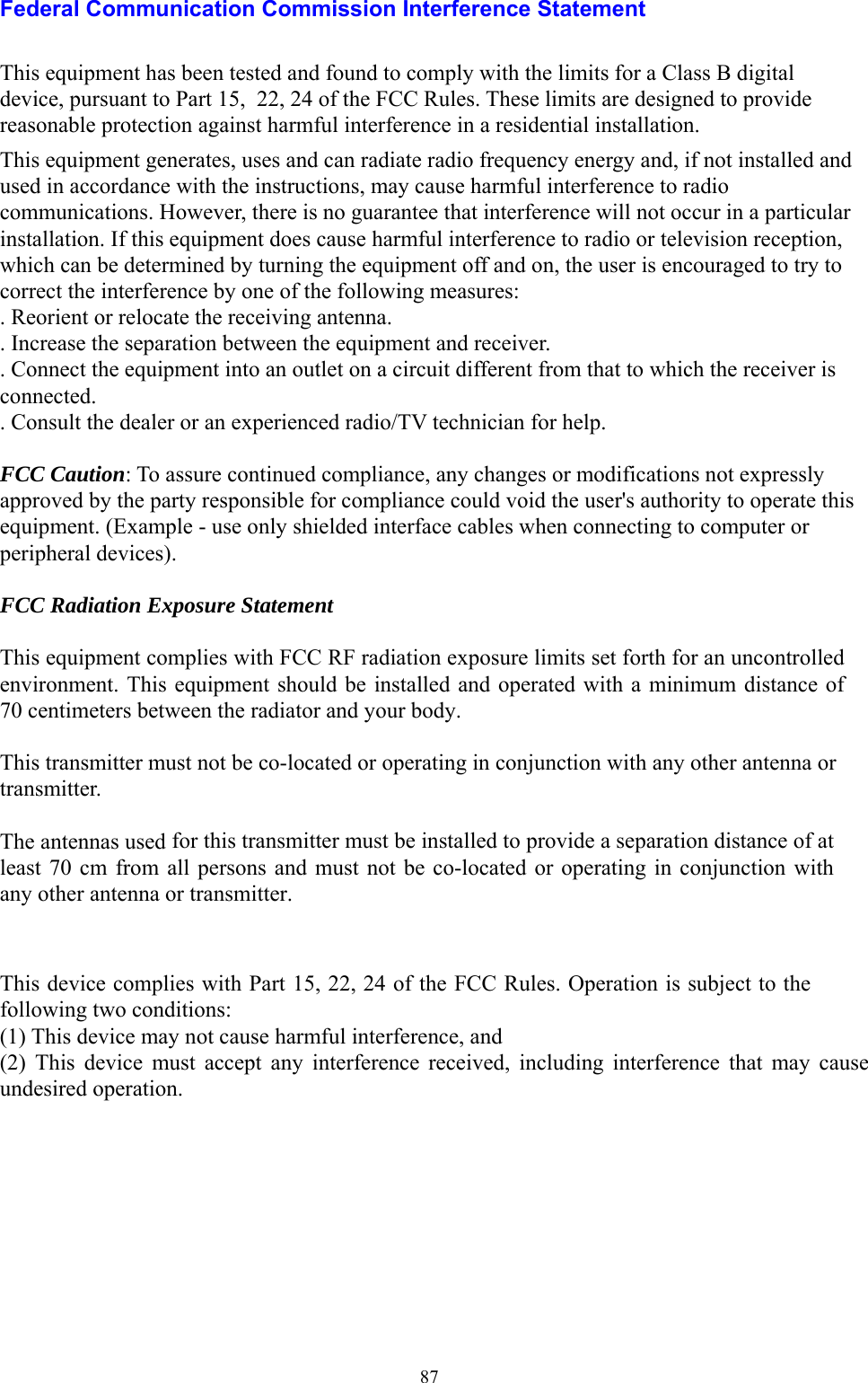
HSGW3G User Manual
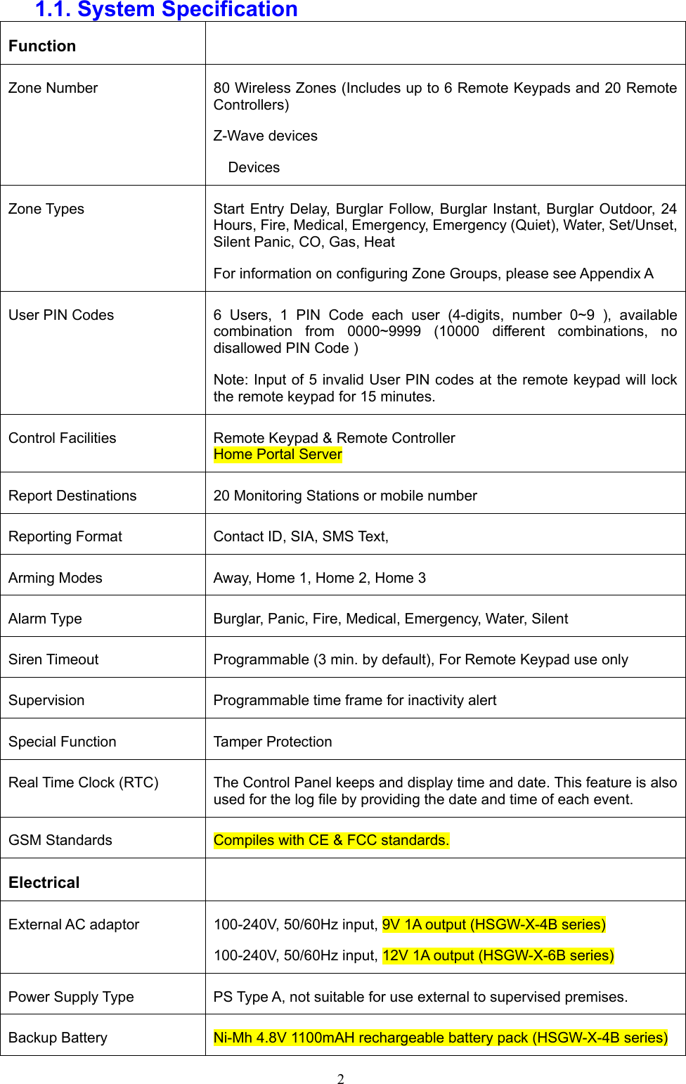
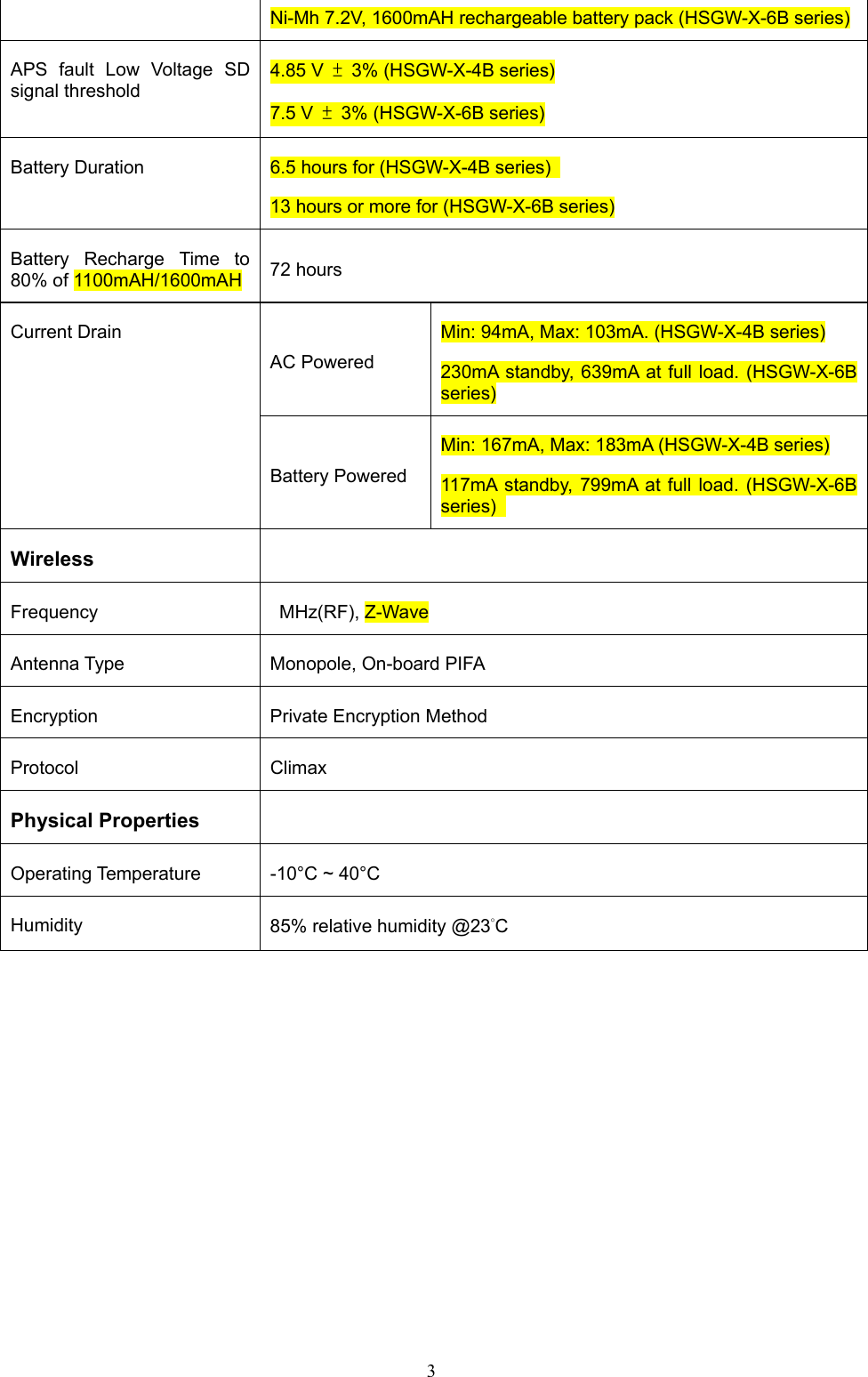
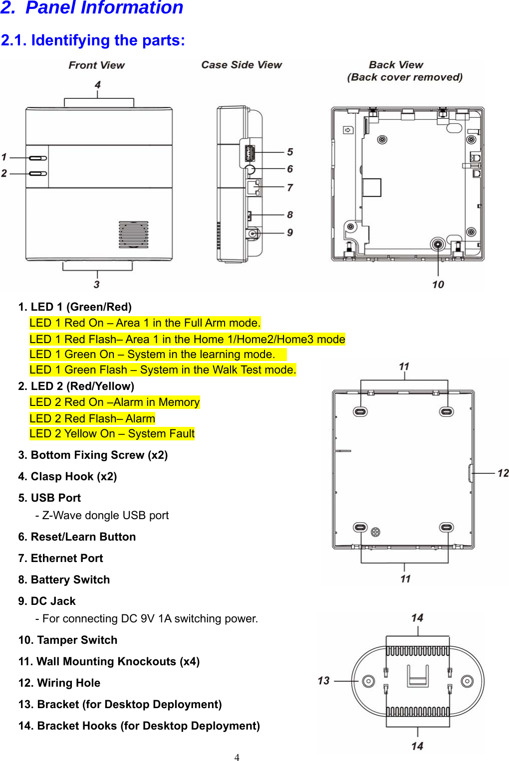
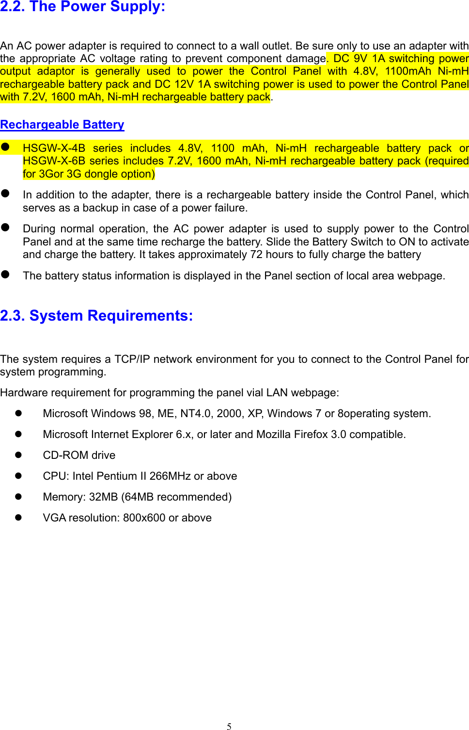
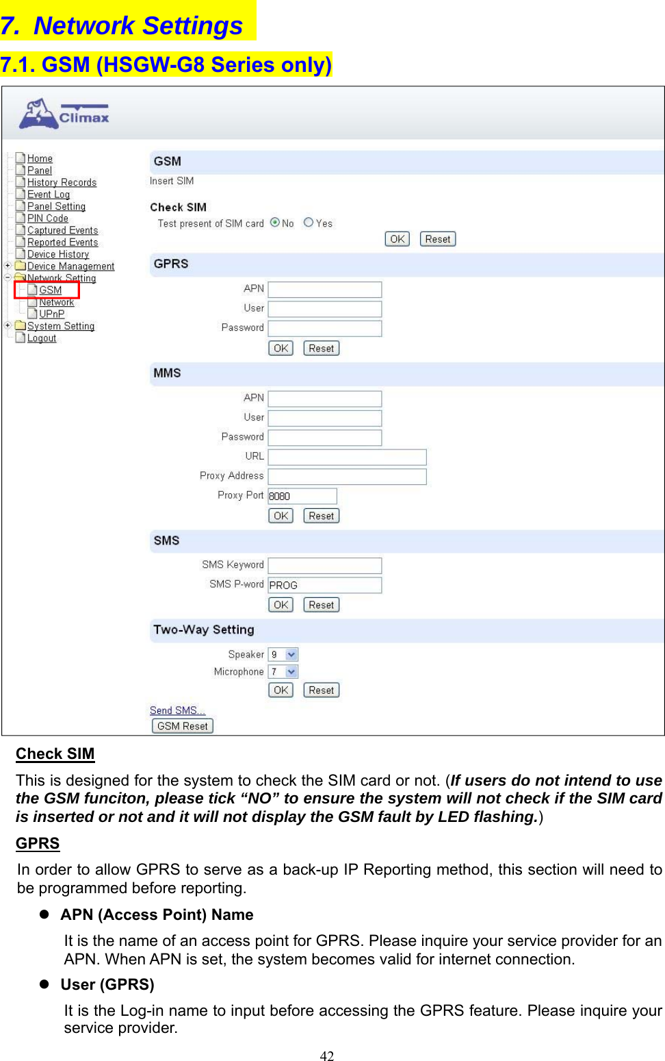
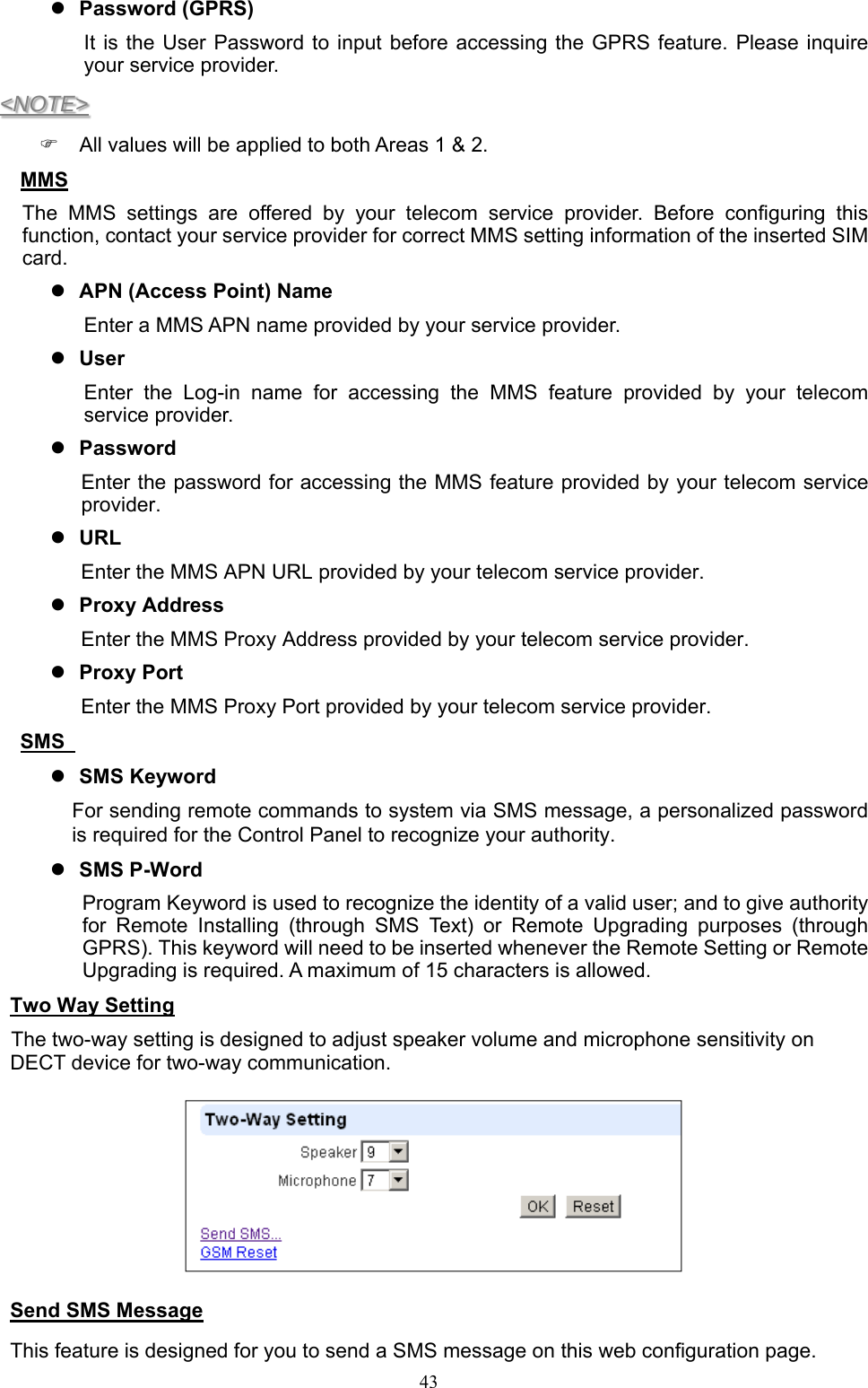
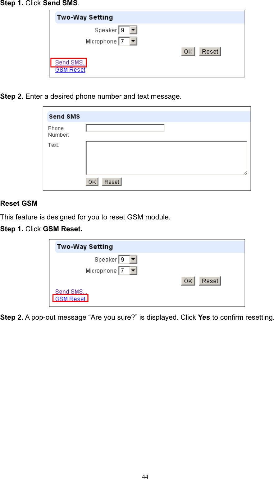
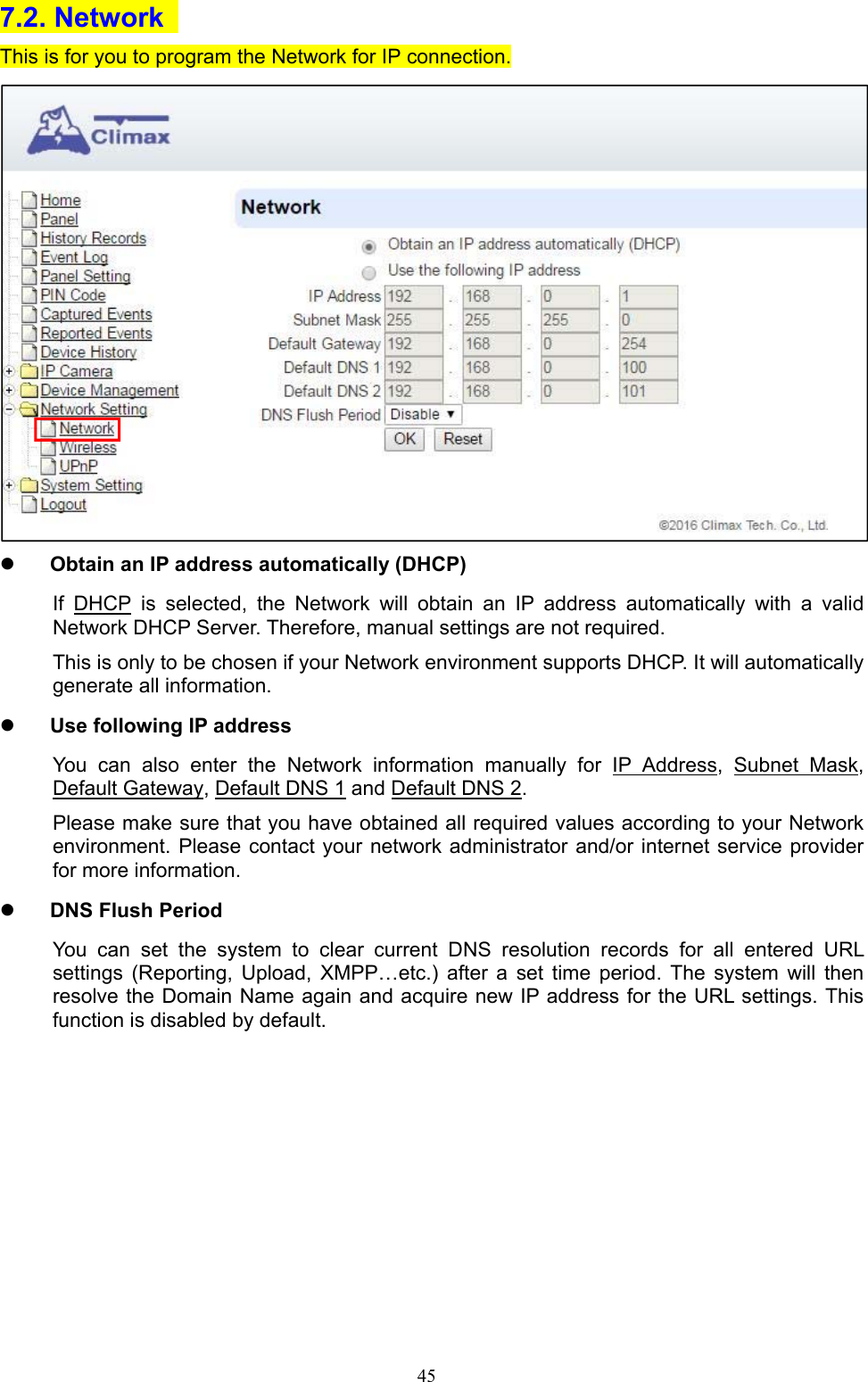
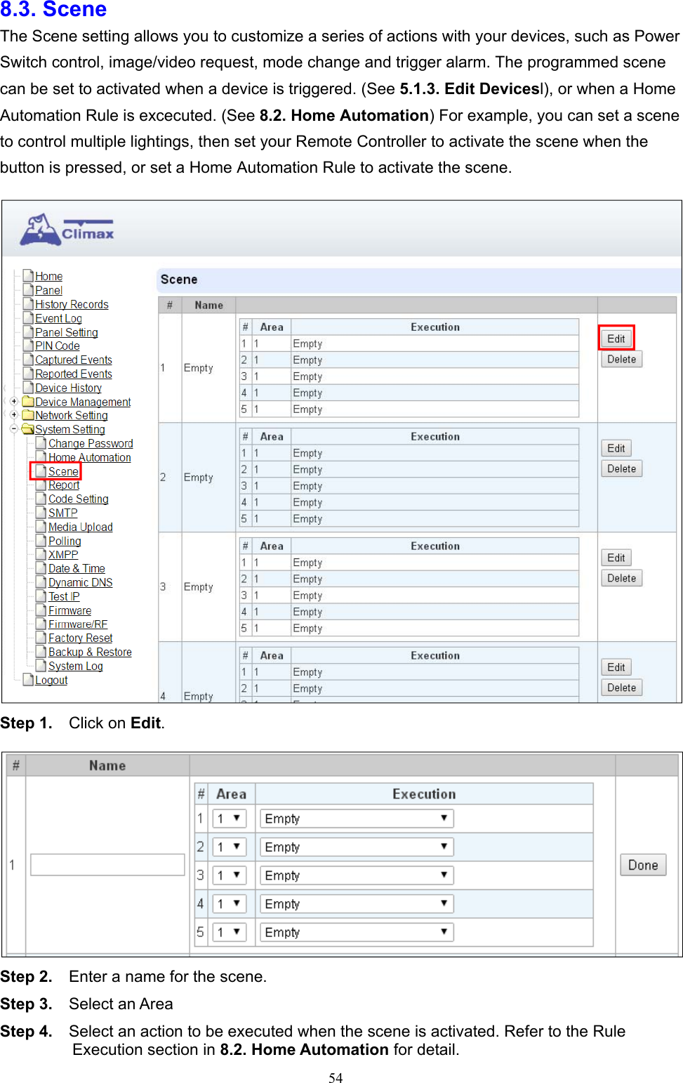
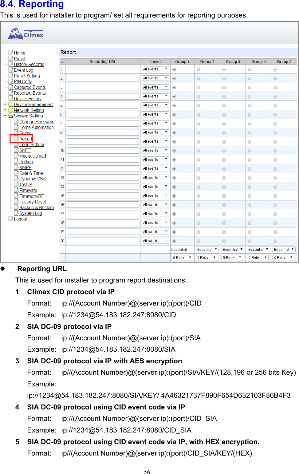
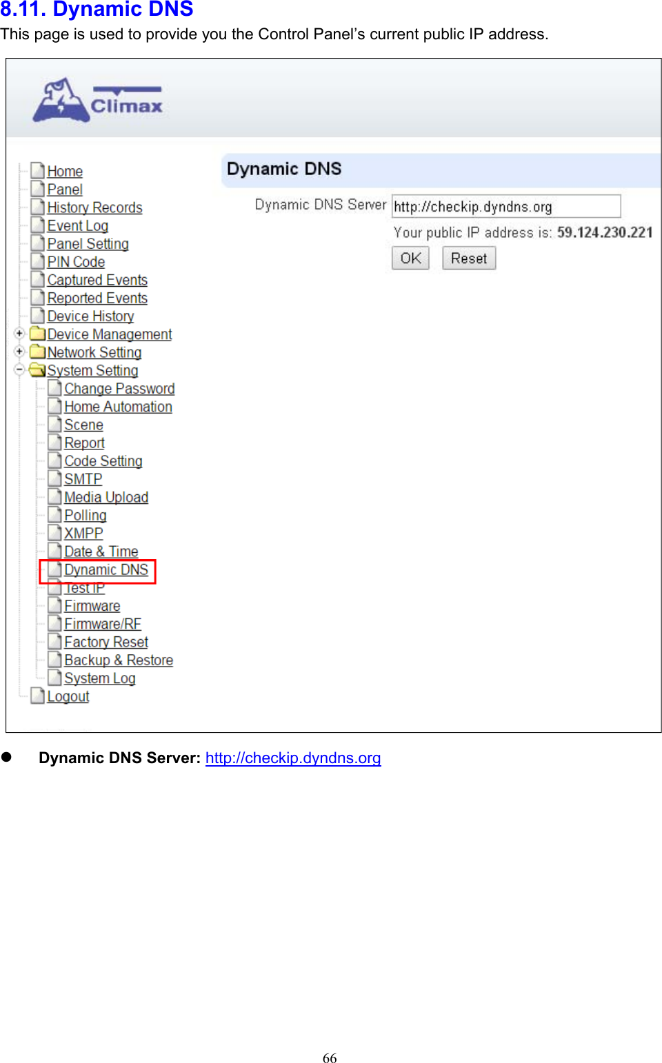
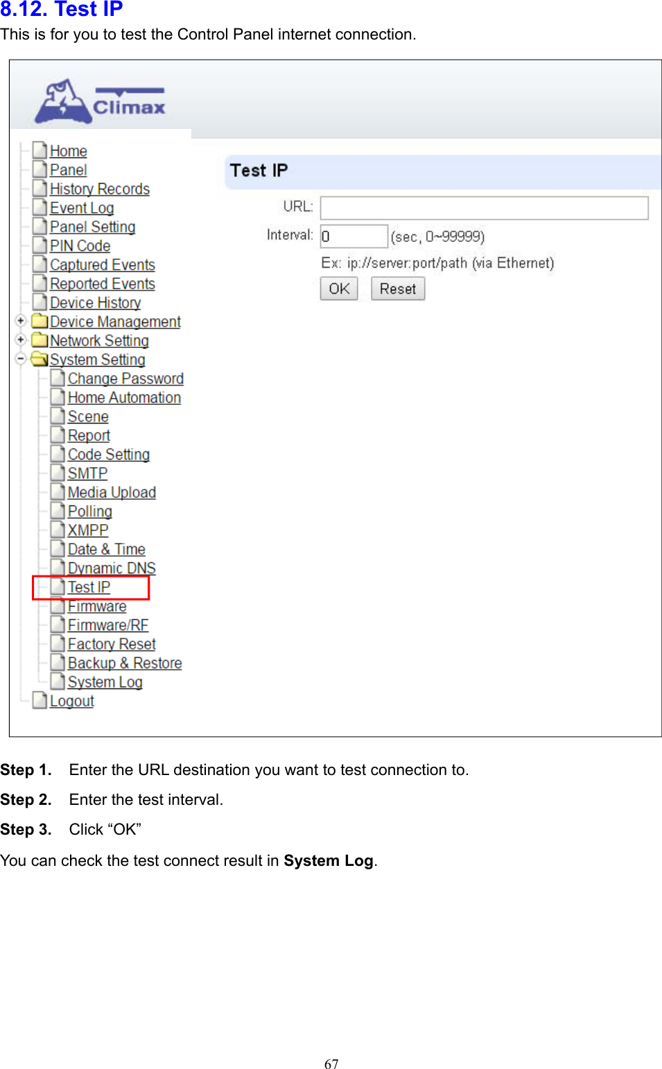
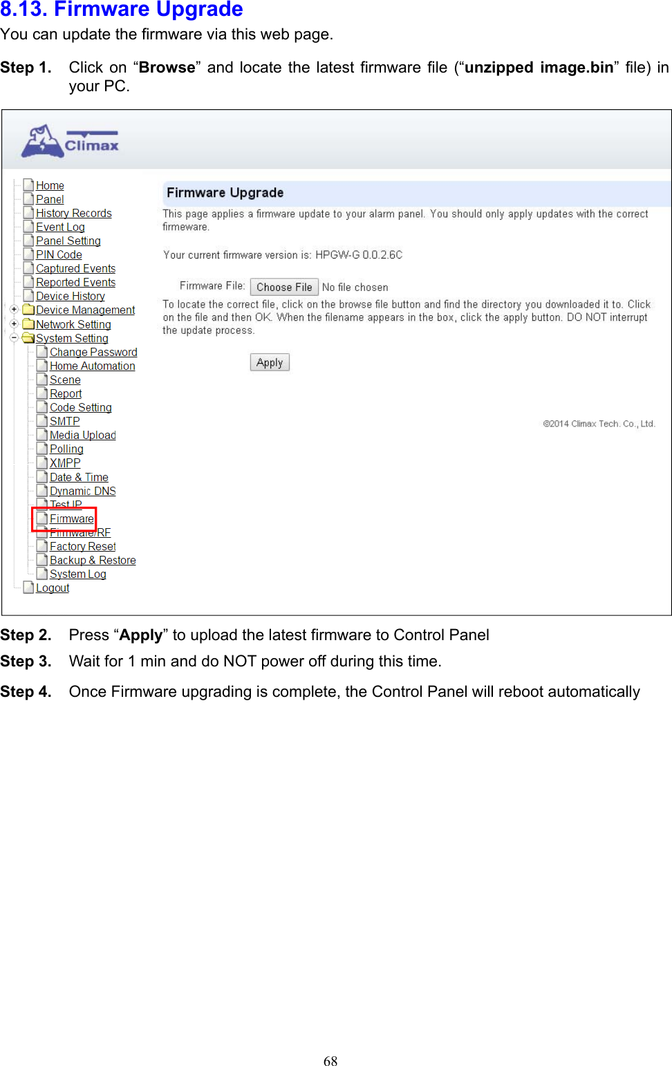
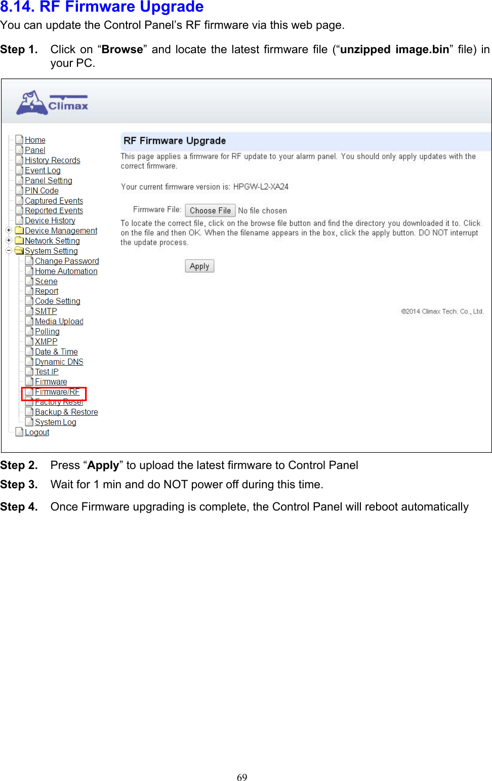
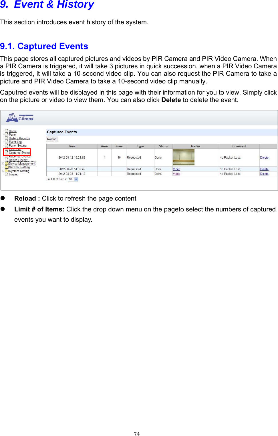
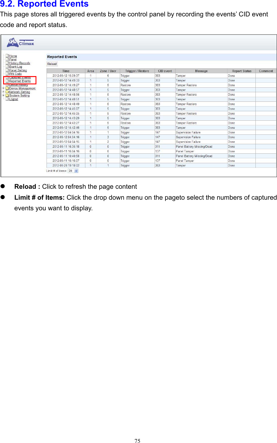
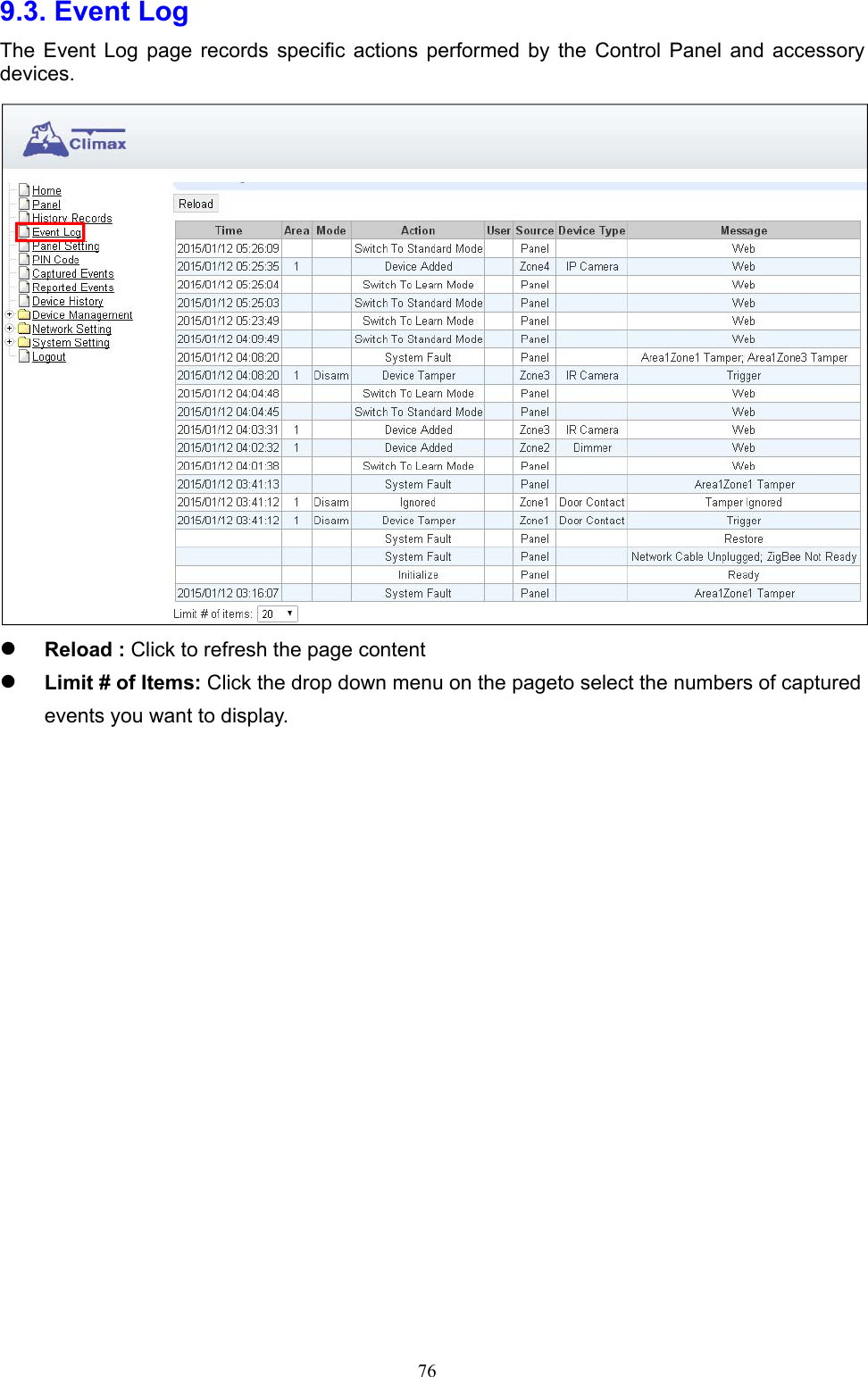
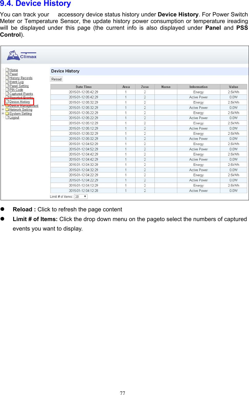
Users Manual
Navigation menu
Upload a User Manual
Namespaces
Wiki Guide
HTML
PDF
Info
Views
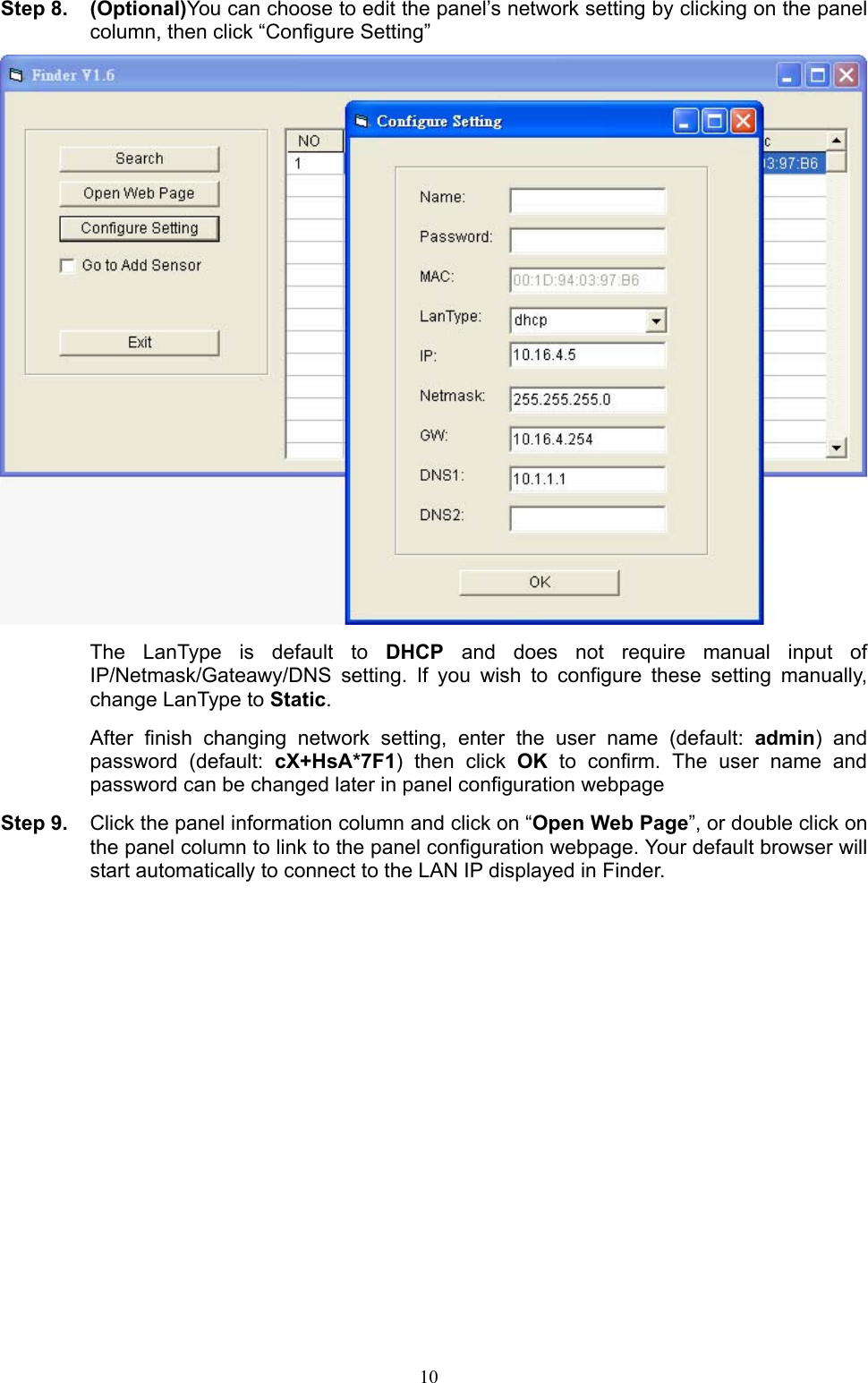
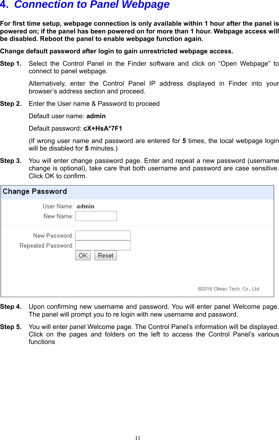
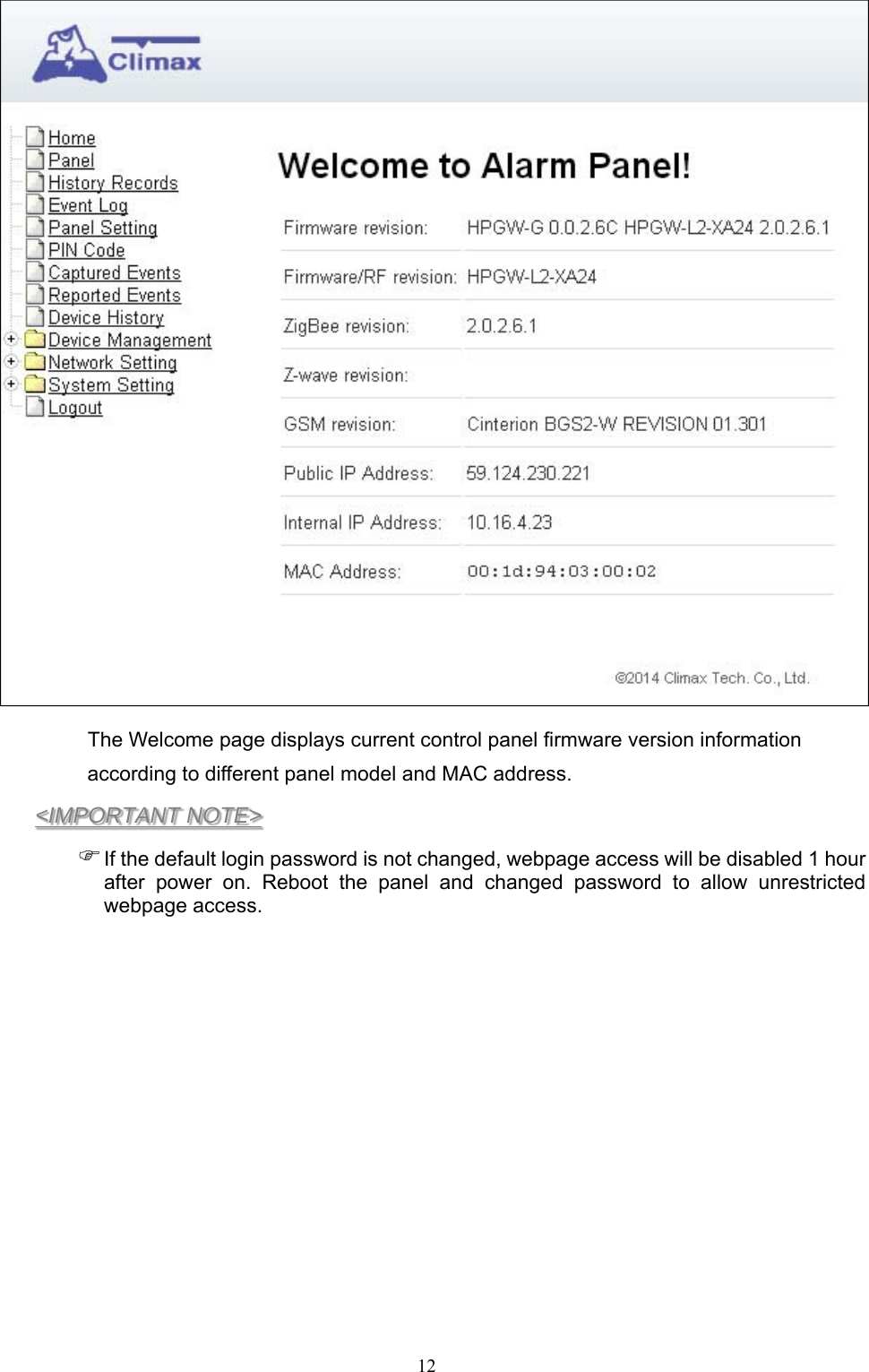
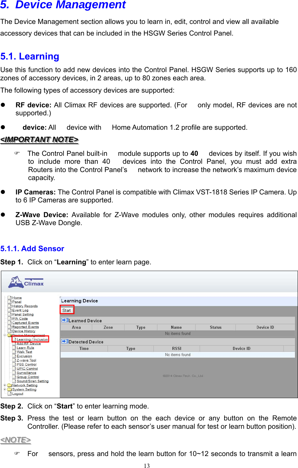
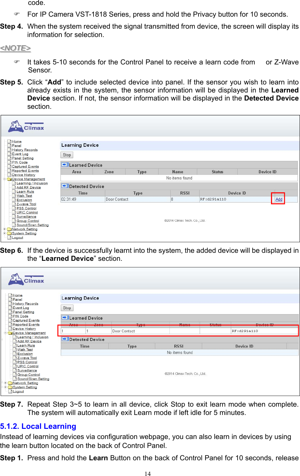
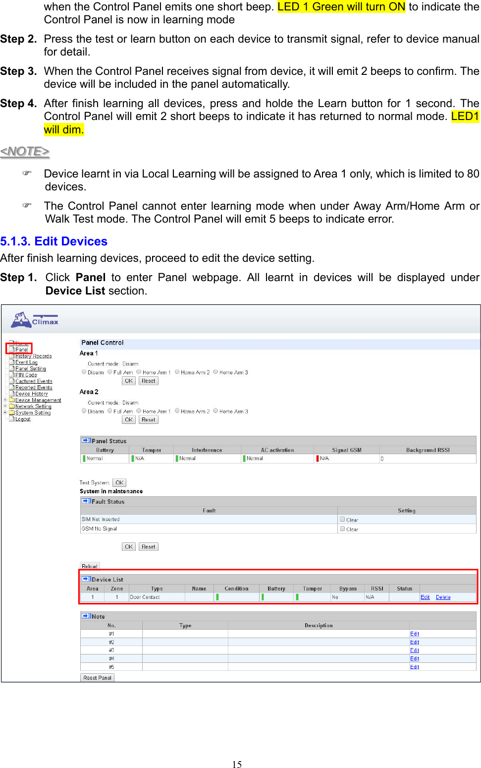
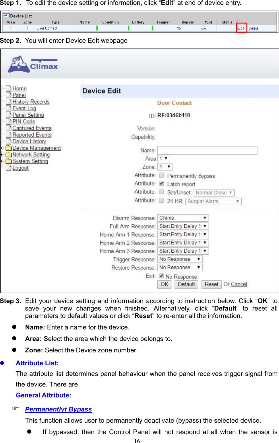
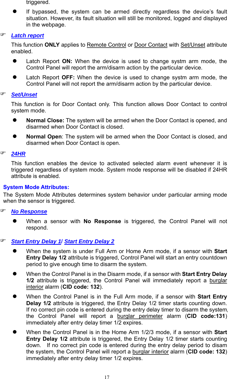
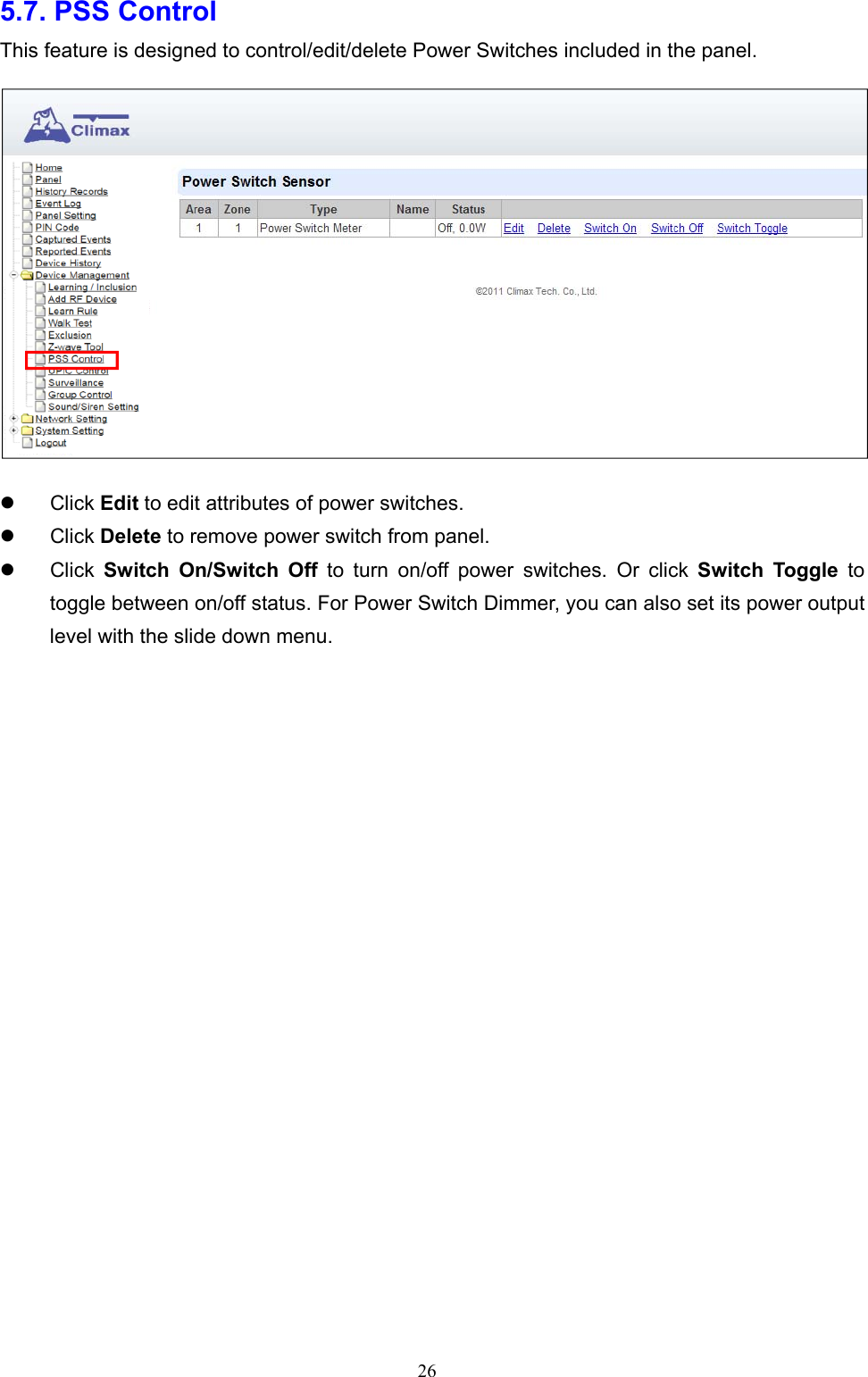
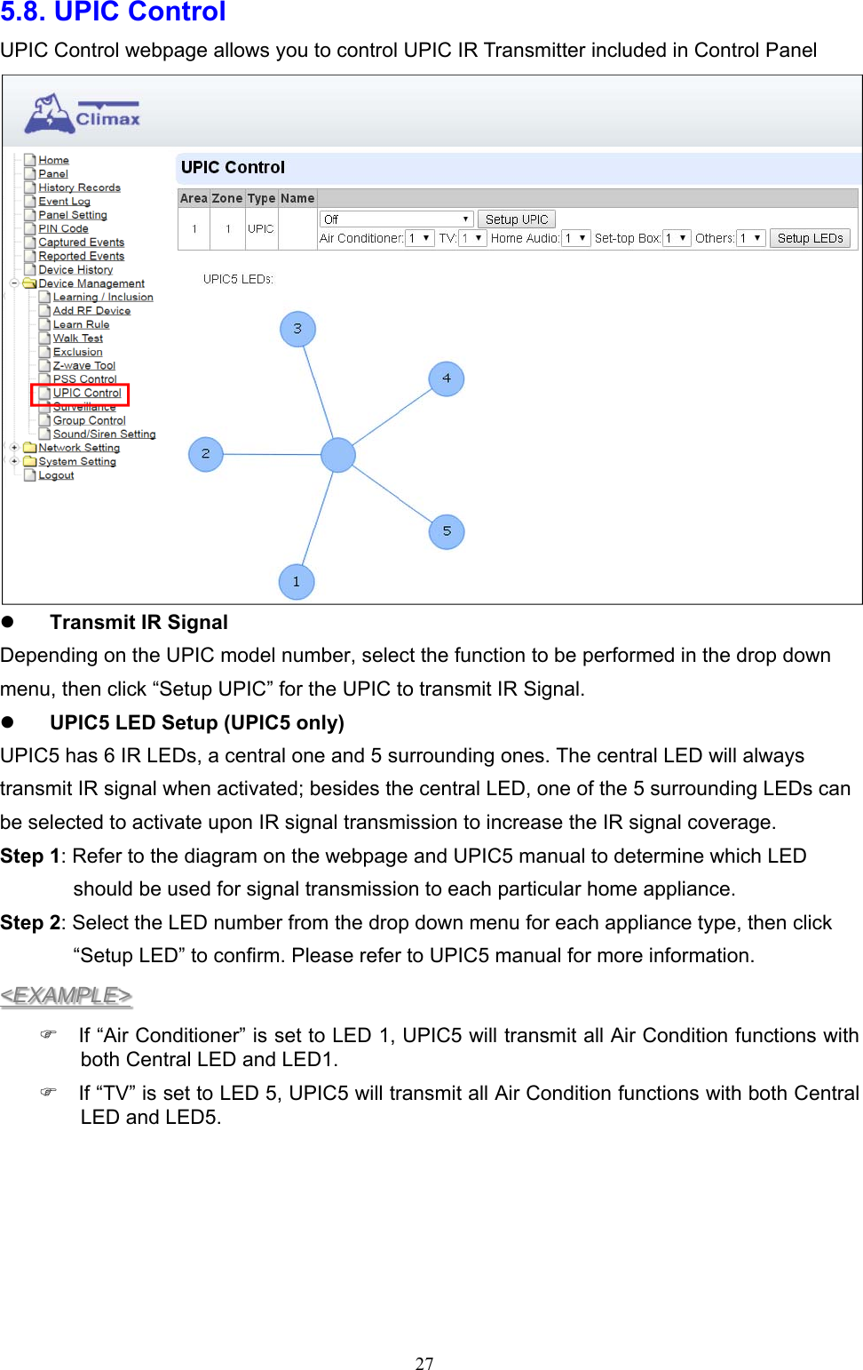
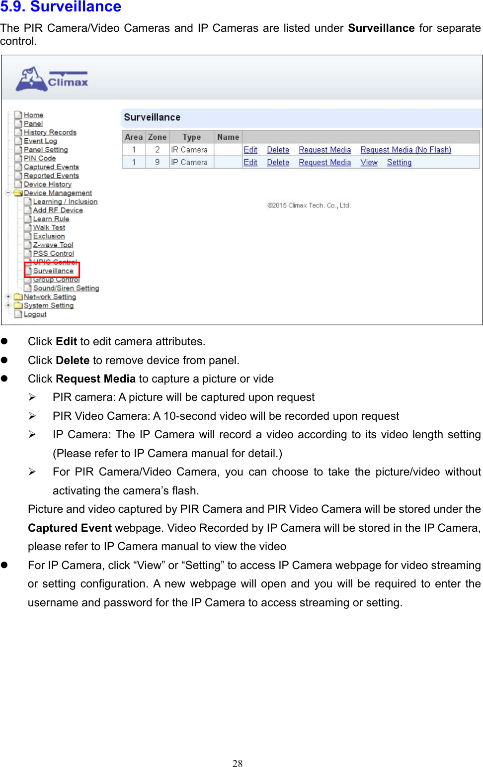
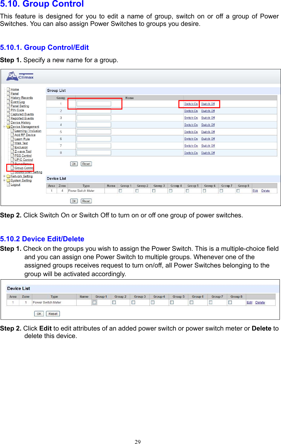
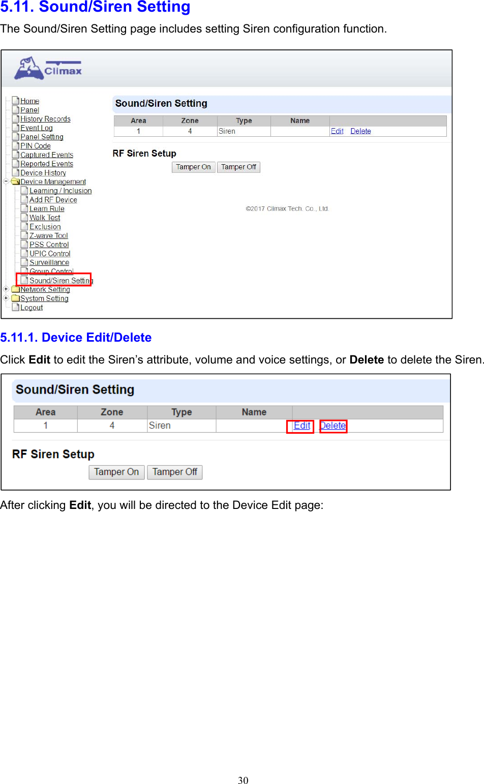
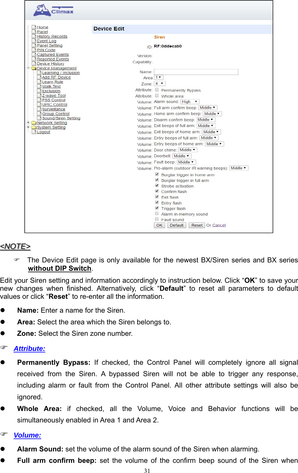
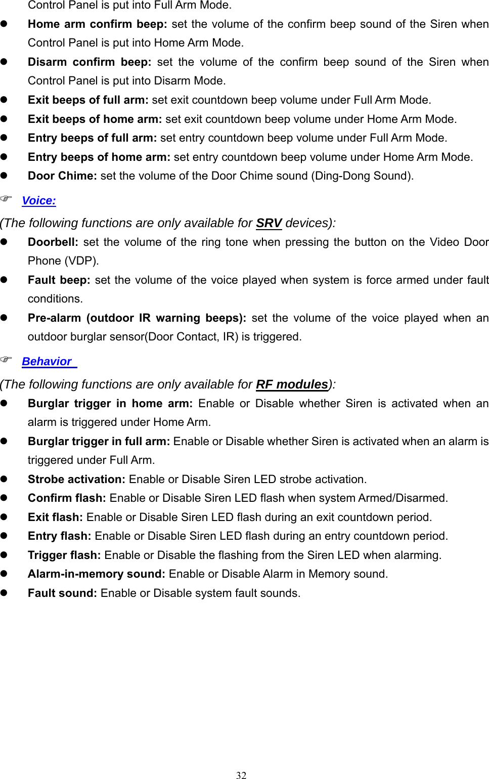
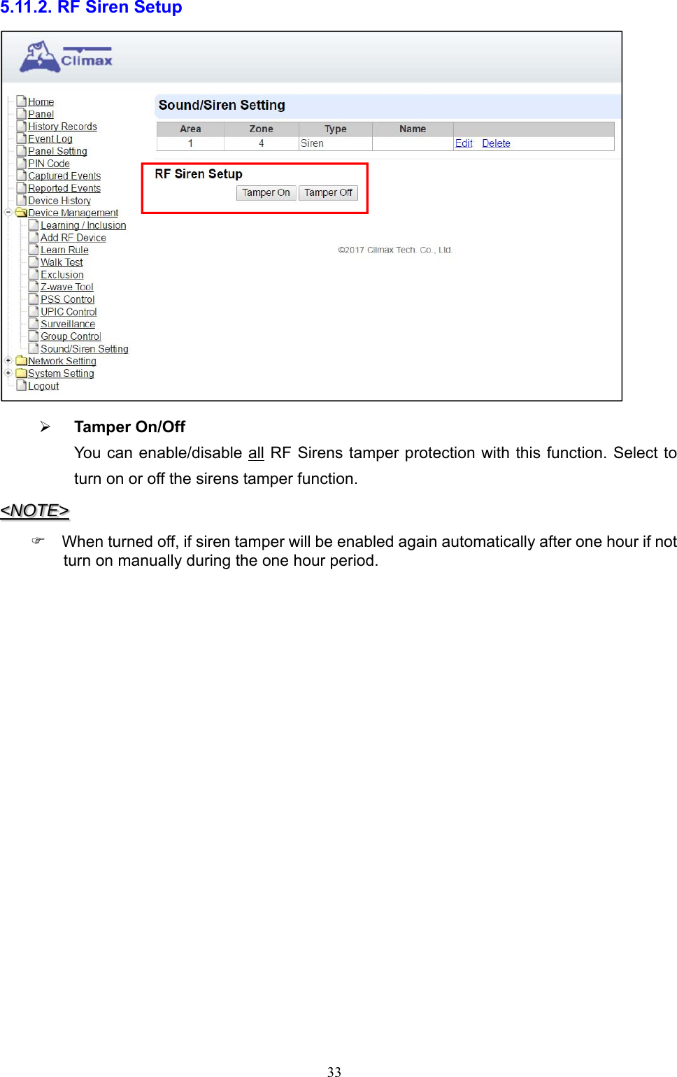
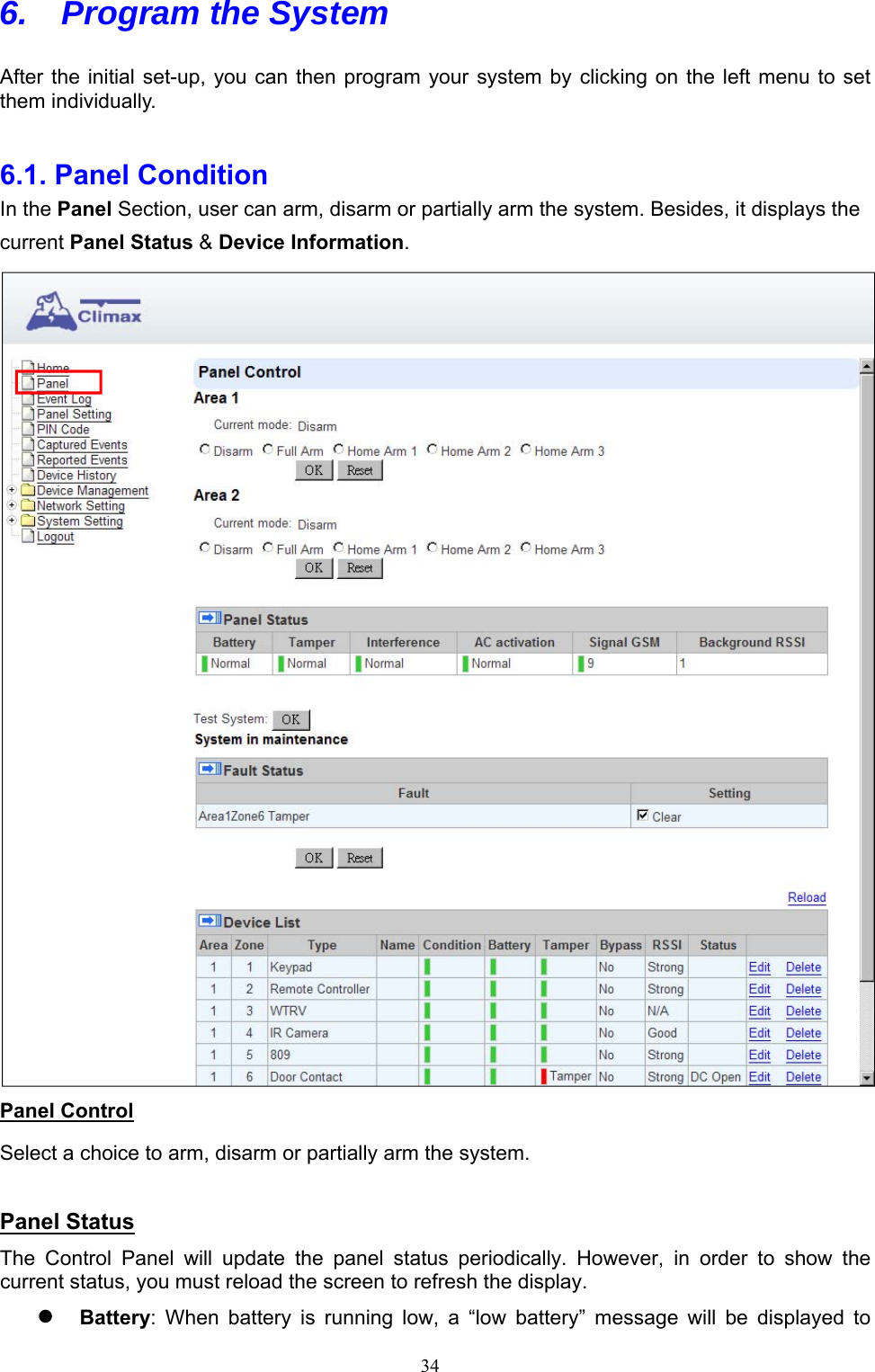
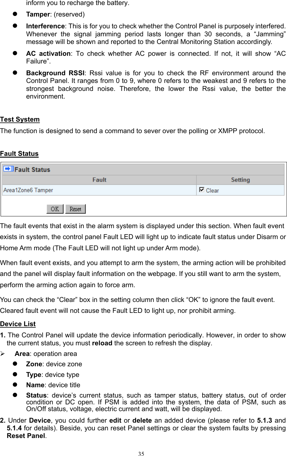
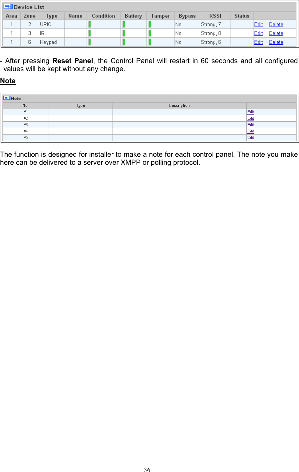
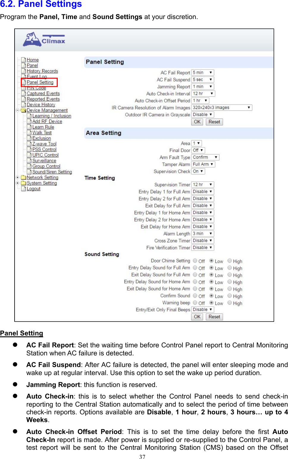
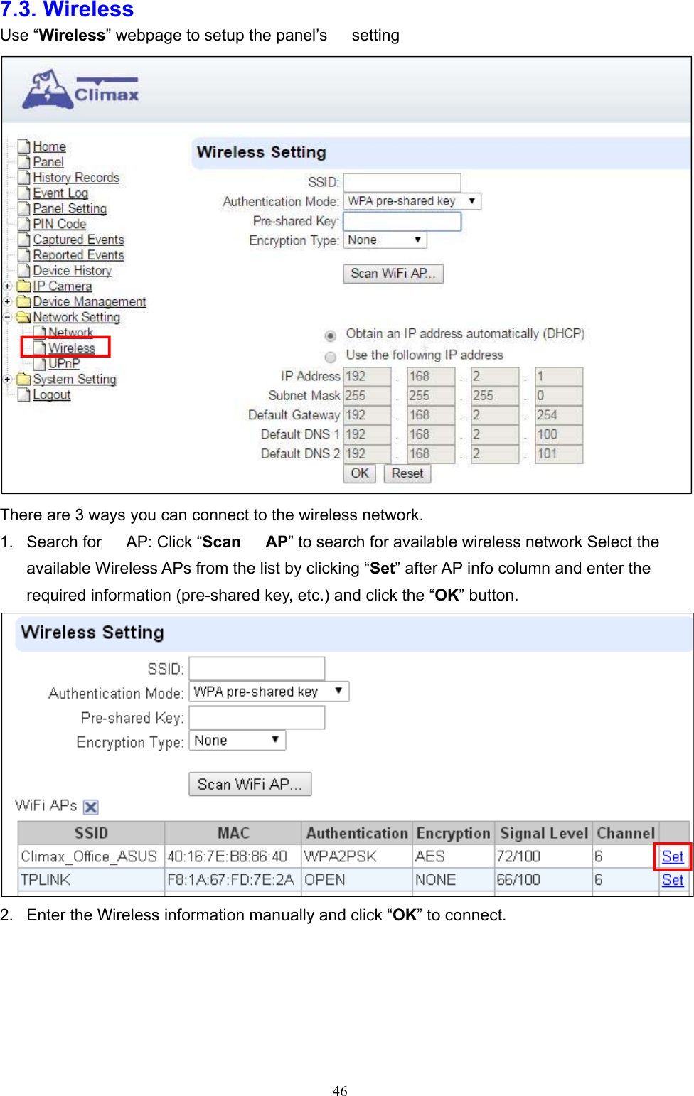
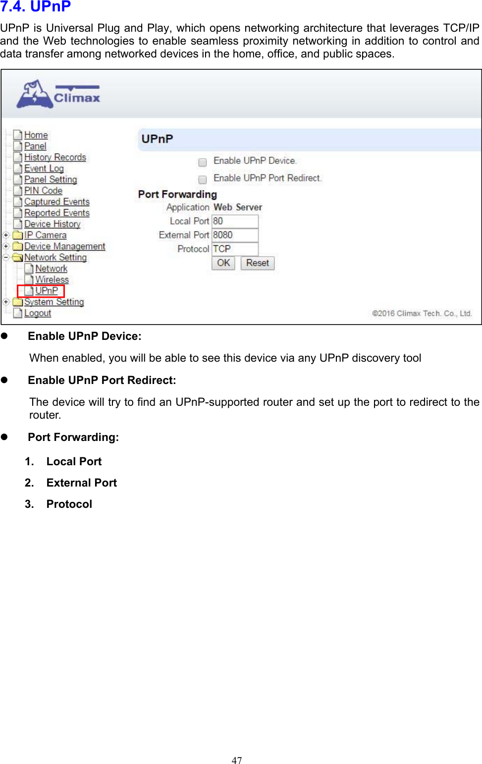
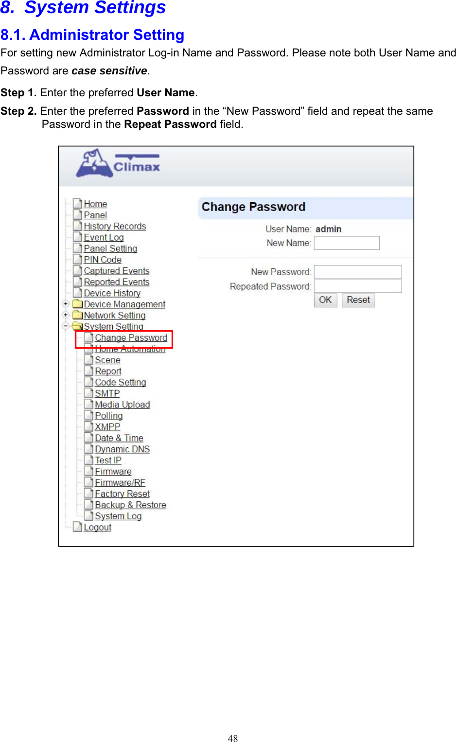
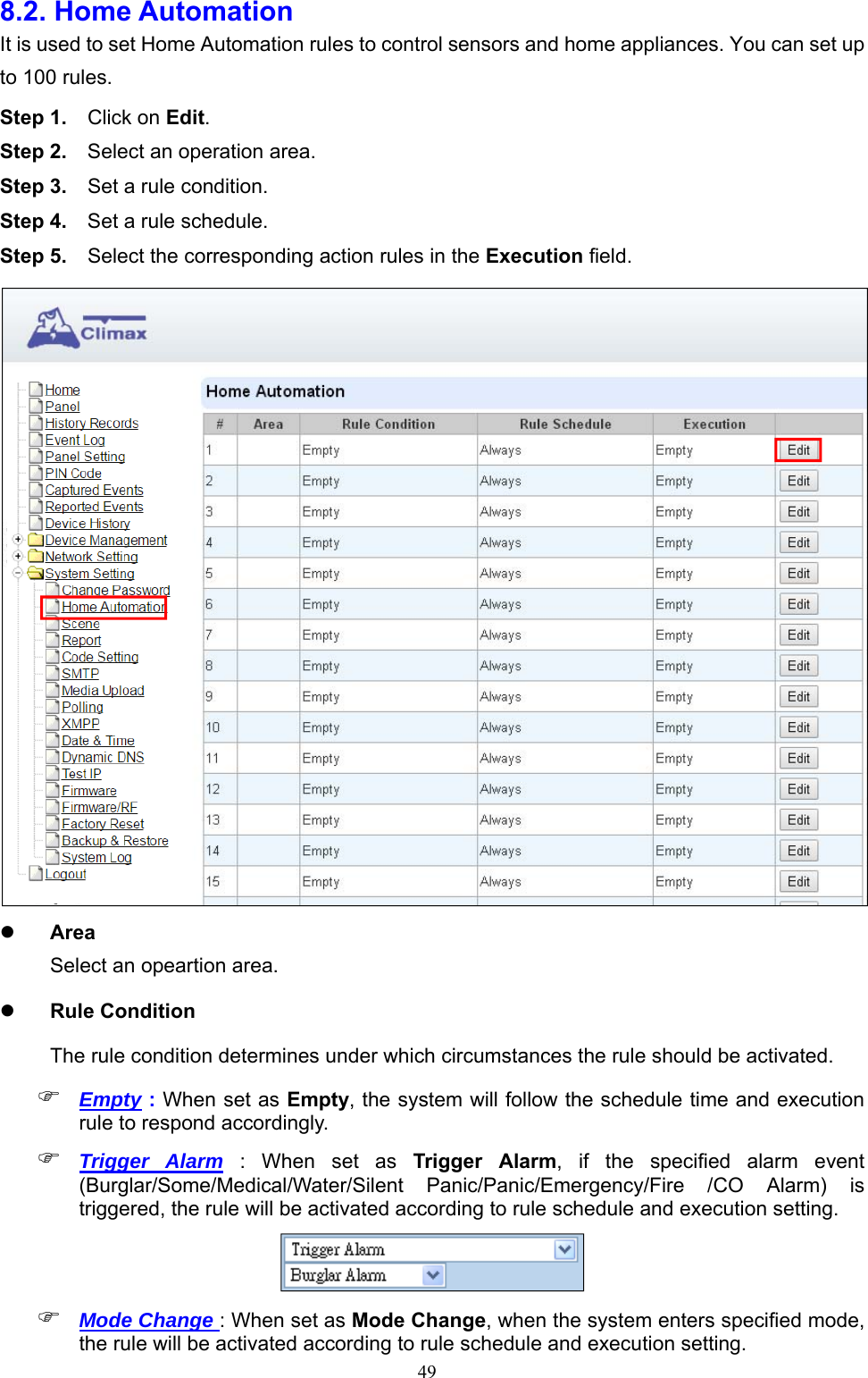
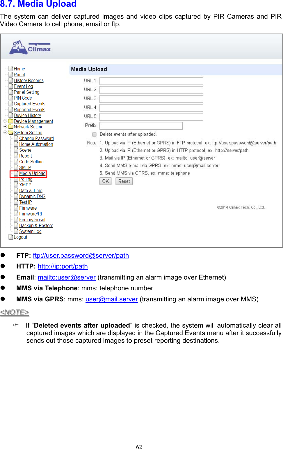
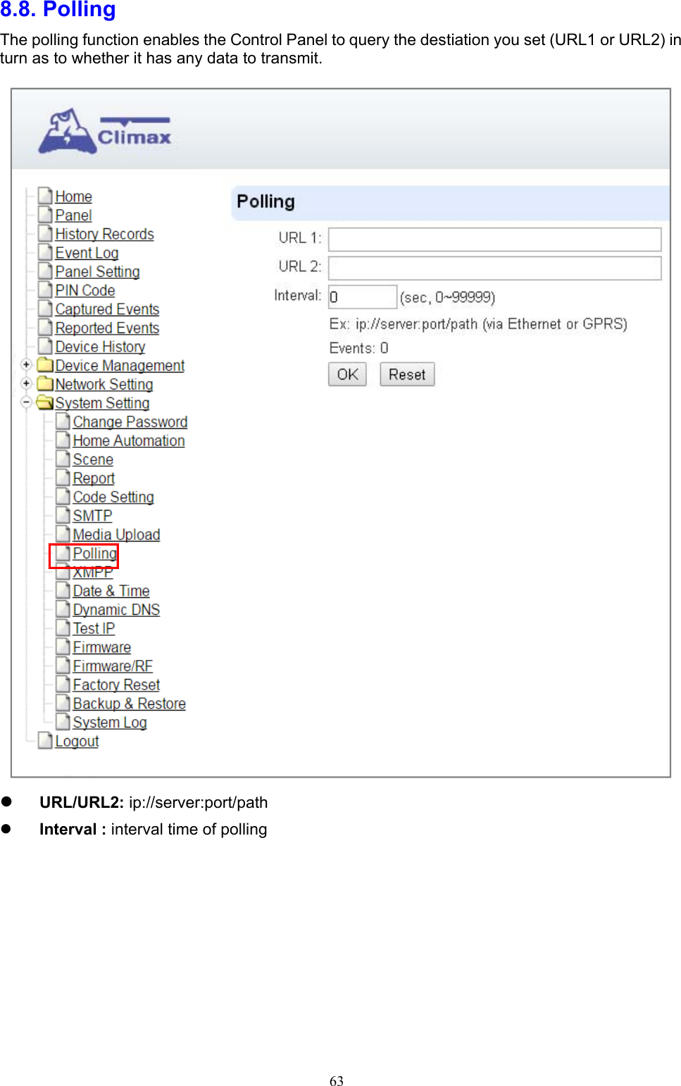
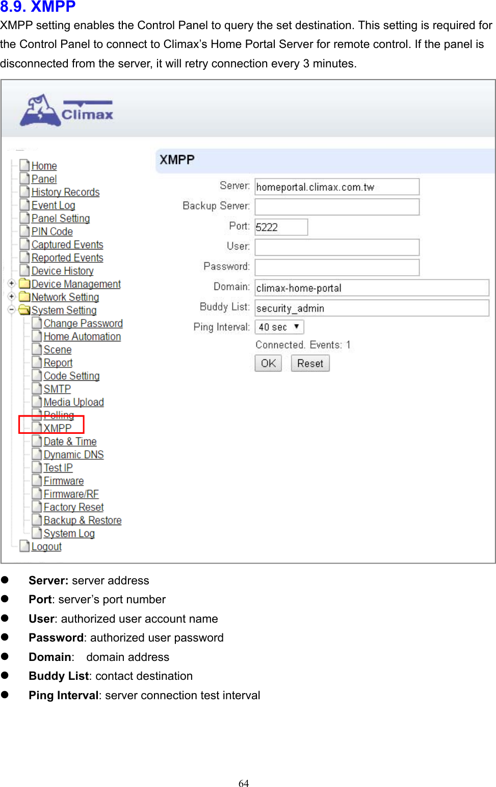
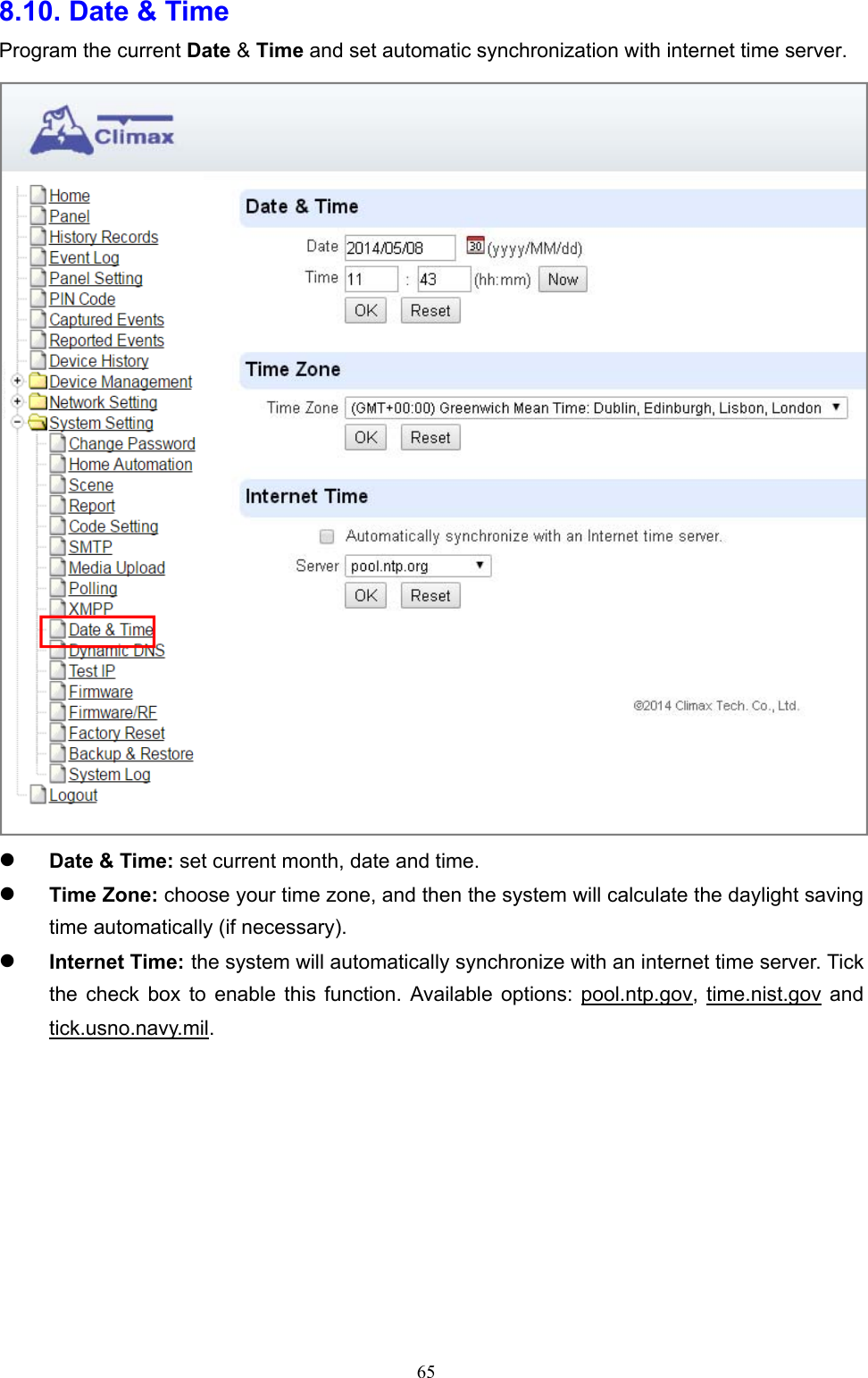
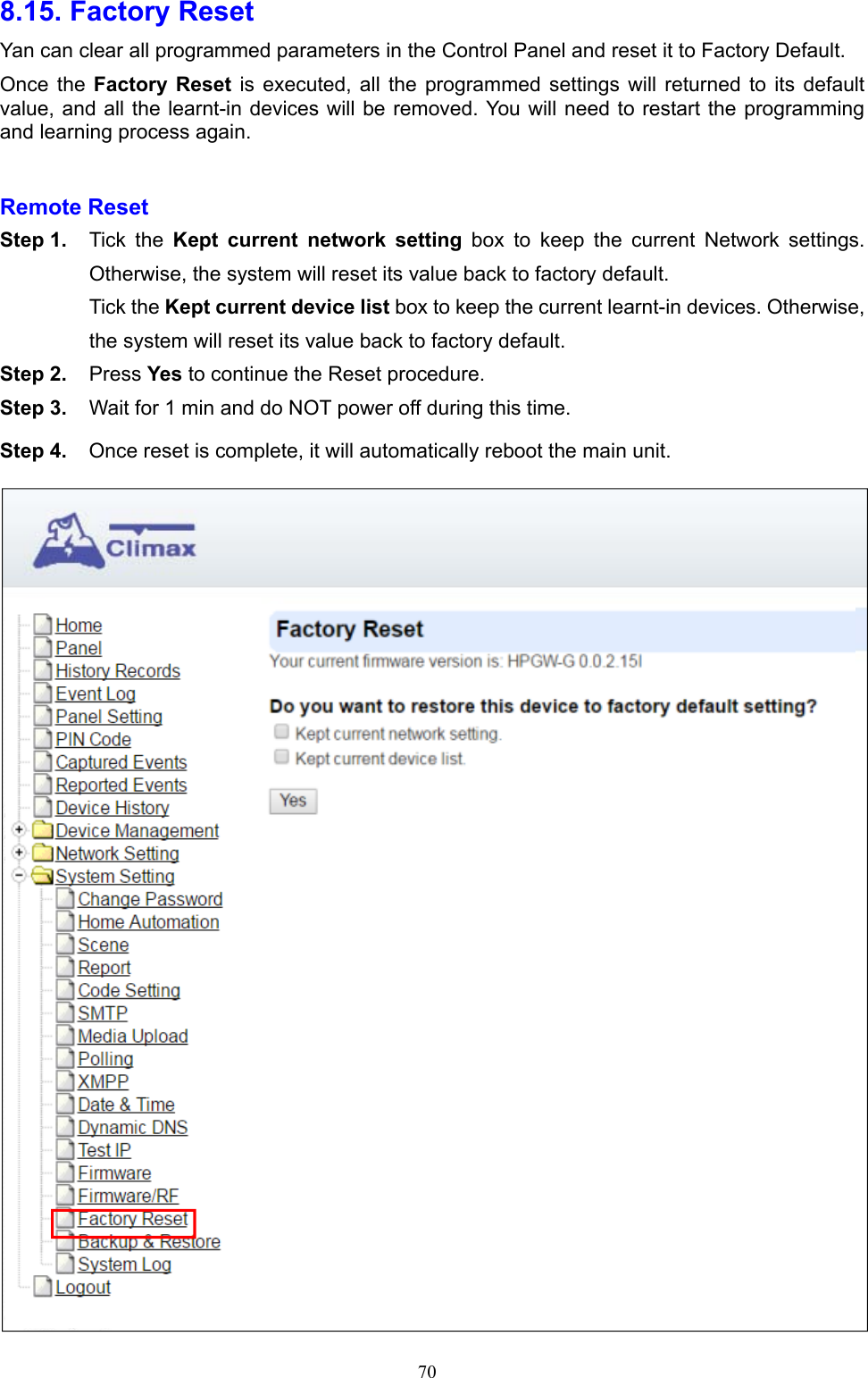
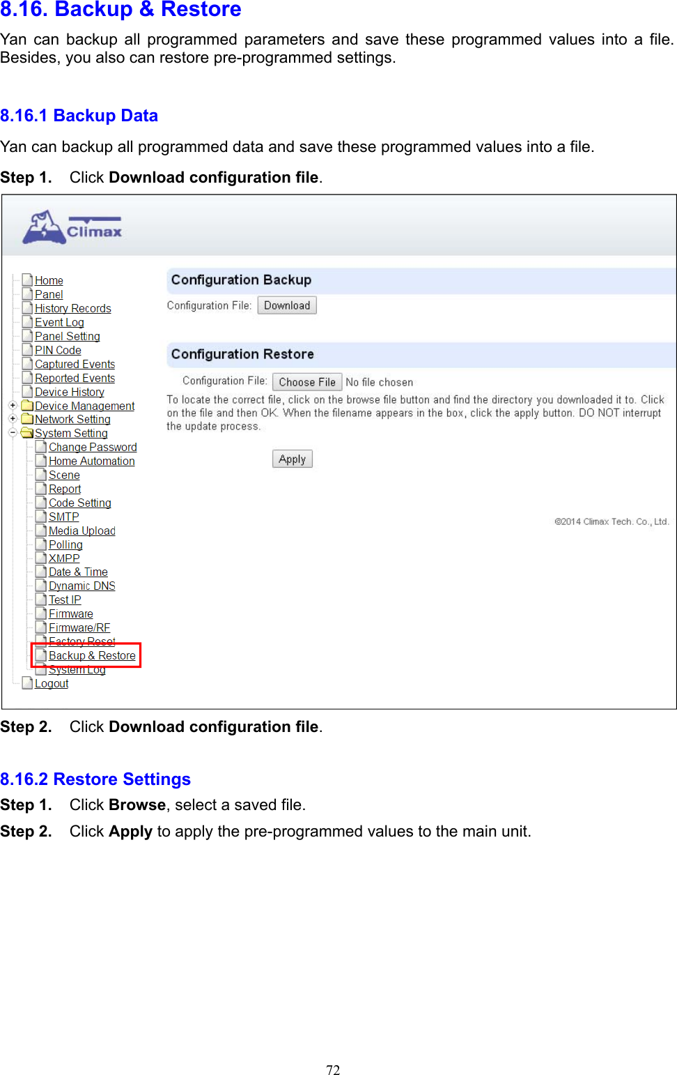
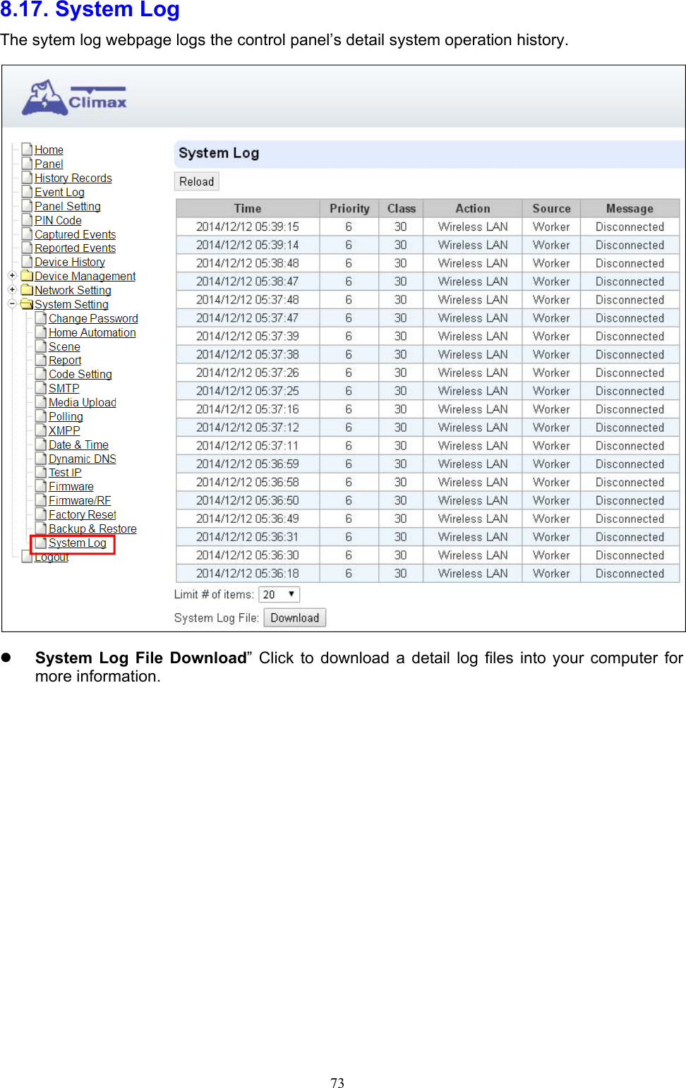
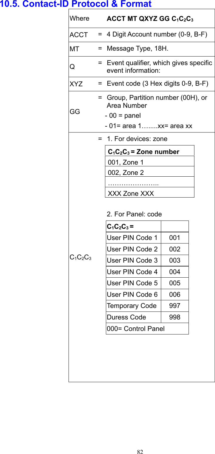
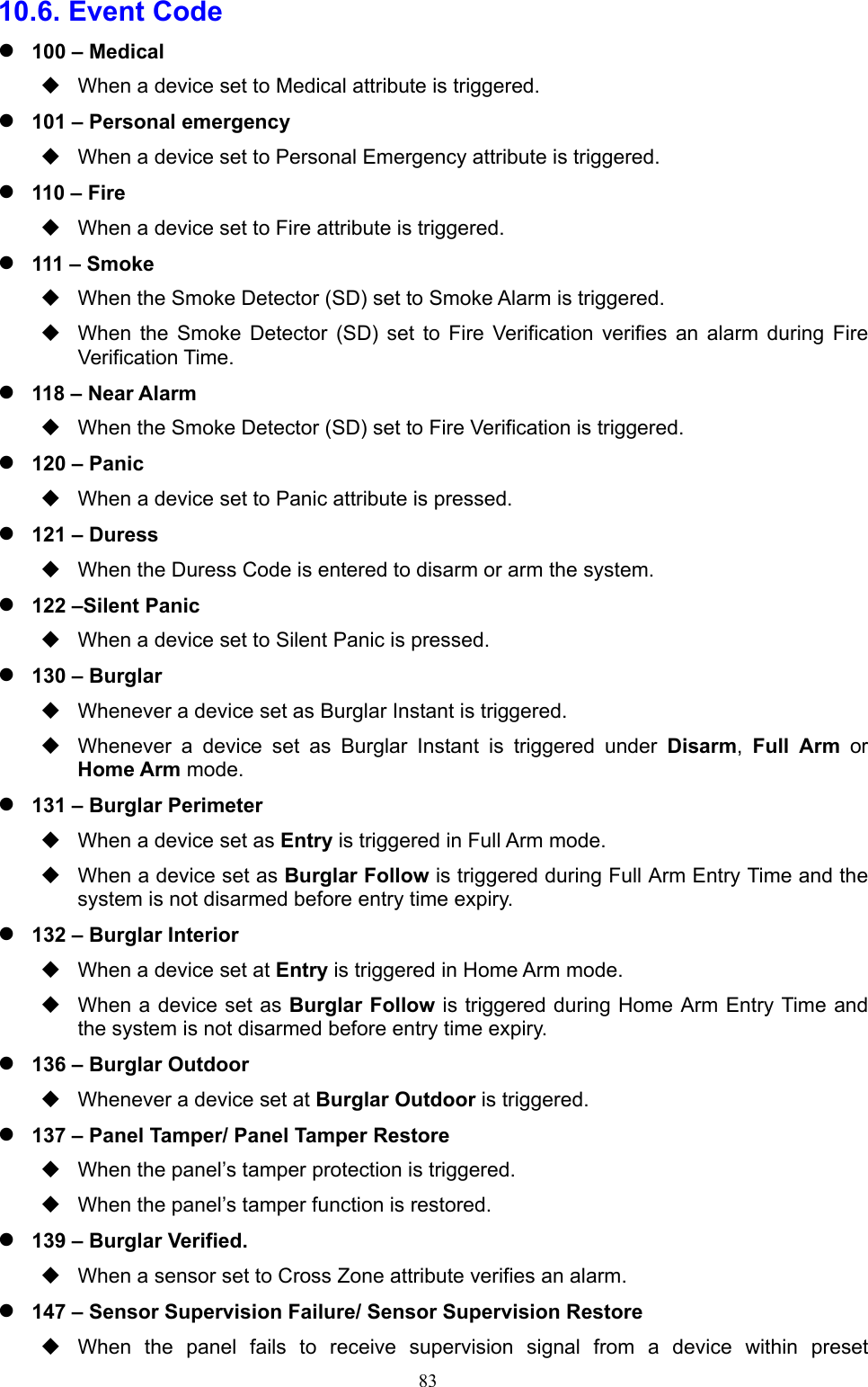
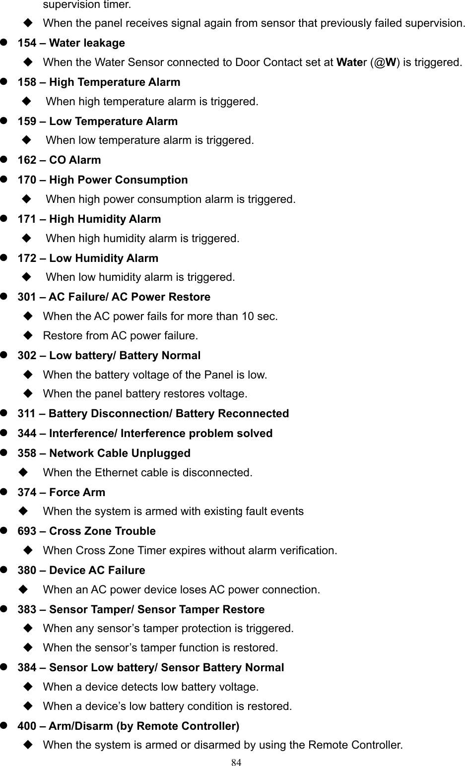
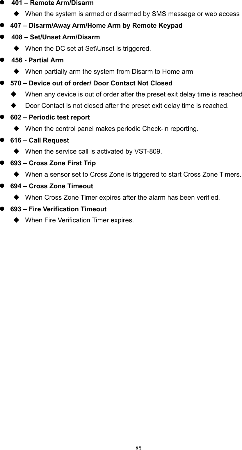
User Manual
Discussion / Help
Navigation