Climax Technology Co IRP9 PET IMMUNE PIR Motion Sensor User Manual IRP 9
Climax Technology Co Ltd PET IMMUNE PIR Motion Sensor IRP 9
Users Manual
D.A.S.P. PET IMMUNE PIR Motion Sensor (IRP-9)
The PIR Pet-Immune Motion Sensor ensures the excellent catch performance of its original purpose in the security sense
and in addition, eliminates unnecessary false alarms caused by those jumpy little loved pets. IRP-9 is designed to detect
movements within an assigned area and signals the Control Panel to activate the alarm if an intruder crosses its’ path of
detection but will not detect a dog up to 27 kilos, 10 cats, or numerous rodents.
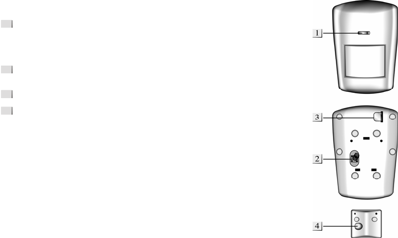
The PIR consists of a two-part design made up of a cover and a base. The cover contains all the electronics and optics and
the base provides a means of fixing. The base has knockouts to allow mounting on either a flat surface or in a corner
situation with a triangular bracket for corner mounting.
Provision for a tamper switch that will be activated when the cover is detached from the base prevents unauthorized access
and removal from the mounting surface. The PIR can also alert you to signal communication problems and low battery
situations.
The PIR is designed to give a typical detection range of 12 meters when mounted at 2 meters above ground.
z
z
I
Id
de
en
nt
ti
if
fy
yi
in
ng
g
t
th
he
e
p
pa
ar
rt
ts
s.
.
Test Button aka LED indicator
It is the test button and also doubles as the LED indicator. The test button is
used for testing the radio performance and for learning purpose. The LED
indicator is used to indicate the status of system.
Tamper Switch
The Tamper switch protects the enclosure from being opened.
Battery Insulator
Corner mounting bracket
z
z
S
Su
up
pe
er
rv
vi
is
si
io
on
n
F
Fu
un
nc
ct
ti
io
on
n
When the PIR is in Normal operation mode it will conduct a Self-test randomly by
transmit a supervisory signal once between every 20 minutes to 50 minutes
If the Control Panel doesn’t receive the Supervisory signals transmitted from a
certain PIR, an “Out-Of-Order” fault message will be generated.
z
z
S
Sl
le
ee
ep
p
T
Ti
im
me
er
r
The PIR has a “sleep time” of approximately 1 minute to conserve power. After
transmitting a detected movement, the PIR will not retransmit for 1 minute; any
further movement detected during this sleep period will extend the sleep time by
another minute. In this way continuous movement in front of a PIR will not unduly
exhaust the battery.
z
z
T
Te
es
st
t
m
mo
od
de
e
The PIR can be put into Test mode by pressing the Test Button aka LED on the front cover. In Test mode, it will
disable the sleep timer and will enable the LED indicator to flash every time a movement is detected. Each time
press the Test Button, the PIR will transmit a test signal to the Control Panel for radio range test and enter the test
mode for 3 mins. It will exit Test Mode automatically after 3 mins and returns to normal mode.
z
z
L
LE
ED
D
I
In
nd
di
ic
ca
at
to
or
r
In Normal operation mode, the LED Indicator will not light except in the following situations:
z When the PIR is in low battery condition, every time it transmits a detected movement, the LED will flash for
about 2 seconds.
z When the cover is opened and the tamper switch is violated, the LED will light up for 2 sec. to indicate it is
transmitting the “Tamper” signal.
z When the Tamper condition persists, every time it transmits a detected movement, the LED will light up.
However, if the PIR is in Test mode, the LED will light up every time a movement is detected.
z
z
B
Ba
at
tt
te
er
ry
y
The PIR uses one 3.6 V Lithium battery as its power source. The PIR will have a typical battery life of 5 years at an
average of 20 activations a day.
Low battery detection operates at a threshold of 3.2V+/-2.4% where the PIR has enough reserve energy to typically
operate for 1 month before complete exhaustion. A low battery signal will be sent to the Control Panel along with
regular signal transmissions for the Control Panel to display the status accordingly.
For each installation, the battery is installed in by the factory before shipment with an Insulator inserted.
z
z
G
Ge
et
tt
ti
in
ng
g
S
St
ta
ar
rt
te
ed
d
z Pull out the battery Insulator steadily.
z The LED indicator steadily flashes for 30 seconds. (The PIR is warming up). During the warming period, the PIR
will not be activated. It is recommended that you stay away from the detection area during this time. After the
warming period is over, the light will turn off and the PIR will be ready for operation.
z Put the Control Panel into “Device +/-“ menu and then select “Add Device” menu.
z Press the test buttons on the front cover.
z Refer to the operation manual of your control panel under the section of “Device +/-“ to complete the learn-in
process.
1
3
4
2
Distance
Height
7M
1M 2M 3M 4M 5M 6M
2.3M
Pet Immune Area
z After the PIR is learnt-in, put the Control Panel into “Walk Test” mode, hold the PIR in the desired location, press
the Test button to confirm this location is within signal range of the Control Panel.
z When you are satisfied that the PIR work in the chosen location, you can proceed with installation.
z
z
M
Mo
ou
un
nt
ti
in
ng
g
M
Me
et
th
ho
od
d
z The PIR is designed to be mounted on either a flat surface or in a corner situation with fixing screws and plugs
provided.
z The base has knockouts, where the plastic is thinner, for mounting purpose. Four knockouts are for surface
fixing and four knockouts are for corner fixing as shown in the picture
z For corner mounting, at user’s own dicretion, an optional triangular bracket is provided to add Back Tamper
Protection. Mount the triangular bracket on he wall first with the two pointing sticks on top facing you. Then, you
can just fit the PIR onto the hooks of the triangular bracket or screw the PIR onto it.
z Surface mounting:
I. Remove the fixing screw and cover assembly.
II. Break through the appropriate knockouts on the base.
III. Using the holes as a template, drill holes in the surface.
IV. Insert the wall plugs if fixing it into plaster or brick.
V. Screw the base into the wall plugs.
VI. Screw the cover back onto its base.
z Corner mounting:
I. Break through the two knockouts on the triangular bracket.
II. Using the two holes as a template, drill holes in the surface of the corner
III. Insert the wall plugs
IV. Screw the triangular bracket into the wall plugs with the two pointing sticks on top facing you.
V. Fit the PIR onto the hooks of the triangular bracket
VI. If necessary, open the PIR by removing the fixing screw and cover assembly
VII. Break through the appropriate corner fixing knockouts.
VIII. Using the corner fixing knockouts as a template, drill holes in the surface in the corner again
IX. Insert the wall plugs if fixing it into plaster or brick.
X. Screw the base into the wall plugs
XI. Screw the cover back onto its base
z
z
I
In
ns
st
ta
al
ll
la
at
ti
io
on
n
z Decide on the location of the PIR and if it is to be corner or surface mounted.
z After the installation site is selected, follow the steps described above to mount the PIR.
z Press the Test Button to enter Test Mode. Walk around the protected area noting when the LED lights up and
check that the detection coverage is adequate.
z When detection coverage is found to be satisfying, installation is now completed.
z
z
I
In
ns
st
ta
al
ll
la
at
ti
io
on
n
R
Re
ec
co
om
mm
me
en
nd
da
at
ti
io
on
ns
s
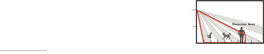
The PIR is designed to give a typical detection range of 12 meters when
mounted at 2 meters above ground. When mounted at 2.3 meters above
ground, it gives a typical PET IMMUNE range of 7 meters. As the PIR is
higher from above ground, it gives a farther PET IMMUNE range. To take
full advantage of IRP-9, the following guidelines should be considered:
z It is recommended to install the PIR in the following locations
z Mount the detector at 2.1 M ~ 2.4 M high for best performance:
<
<I
IM
MP
PO
OR
RT
TA
AN
NT
T
N
NO
OT
TE
E>
>
) For the most desired performance of IRP-9, remember to adjust the height of IRP-9 mounting site
respectively to the height of the tallest animal in the house. As the taller than average dogs require the
IRP-9 to be mounted higher for the Pet Immunity purpose.
) When deciding on the height of the IRP-9 mounting site, remember to take the possible blind spot into
consideration. The blind spot underneath the IRP-9 enlarges proportionally to the height of the IRP-9
mounting site.
z Mount where the animals cannot come to the detection area by climbing on furniture or other objects.
z Don’t aim the detector at stairways the animals can climb on.
z In a position such that an intruder would normally move across the PIR’s field of view.
z In a corner to give the widest view.
z Where its field of view will not be obstructed e.g. by curtains, ornaments etc.
z Limitations
z Do not position a PIR to look directly at a door protected by a Door Contact, this could cause the Door
Contact and PIR radio signals to be transmitted at the same instant when entering, canceling each other out.
z Do not install the PIR completely exposed to direct sunlight.
z Avoid installing the PIR in areas where devices may cause rapid change of temperature in the detection
area, i.e. air conditioner, heaters, etc.
z Avoid large obstacles in the detection area.
z Not pointing directly at sources of heat e.g. fires or boilers, and not above radiators.
z Avoid moving objects in the detection area i.e. curtain, wall hanging etc.
FCC Caution :To assure continued compliance, any changes or modifications not expressly approved by the party responsible for compliance
could void the user's authority to operate this equipment. (Example - use only shielded interface cables when connecting to computer or
peripheral devices).