Climax Technology Co IRZB PIR Motion Sensor User Manual IR P 9
Climax Technology Co Ltd PIR Motion Sensor IR P 9
Users Manual
1
PIR Motion Sensor
Introduction
IR models are ZigBee passive infrared motion sensors (PIR) with optional pet-immune function. It is capable of
sending wireless signals to the coordinator in the ZigBee network upon movement detection.
The PIR is designed to give a typical detection range of 12 meters when mounted at 2 meters above ground.
The pet immune model (IRP-9ZBSSL) has a pet-immune range of 7 meters and will not trigger false alarm from
you household pets within this distance. The PIR also has tamper protections switch which will be activate upon
any attempt of unauthorized cover opening or removal from mounted surface.
The PIR utilizes ZigBee technology for wireless signal transmission. ZigBee is a wireless communication
protocol that is reliable and has low power consumption and high transmission efficiency. Based on the
IEEE802.15.4 standard, ZigBee allows a large amount of devices to be included in a network and coordinated
for data exchange and signal transmission
The PIR serves as an end device in the ZigBee network. It can be included in the ZigBee network to transmit
signal upon activation, but cannot permit any other ZigBee device to join the network through the PIR.
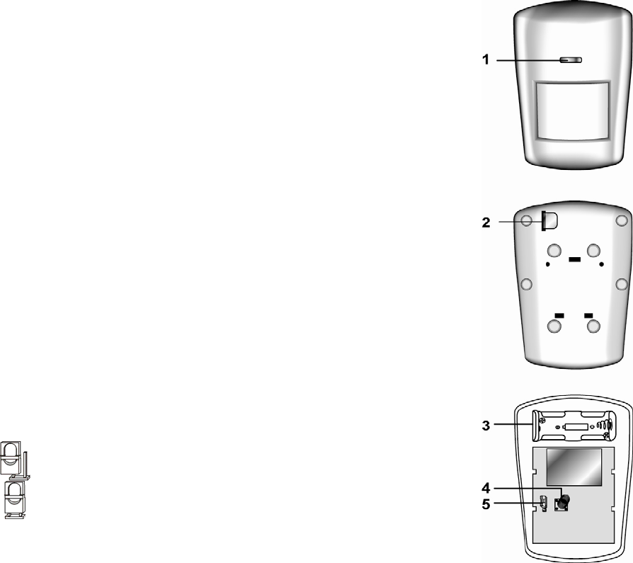
Parts Identification
1. Function Button aka LED indicator
The Function Button also doubles as the LED Indicator. The function button
is used to control the PIR. The LED indicator is used to indicate PIR status.
LED Indication:
The LED indicator lights up in the following conditions:
- Flashes twice quickly:
The PIR has successfully joined a ZigBee network after factory reset.
- Flashes once every 20 minutes:
The PIR has lost connection to its current ZigBee network.
- Flashes under normal operation
The PIR has detected a movement and it is currently under Low
Battery or Tamper open condition.
Function Button Usage:
- Press the button once to send a supervision signal and enter Test
Mode.
- Press and hold the button for 10 seconds then release to reset the PIR.
2. Battery Insulator
3. Battery Compartment
The PIR is powered by one 3V Lithium battery.
4. Tamper Switch
The Tamper switch will be activated when the PIR cover is
opened.
5. Sensitivity Increaser Jumper Switch (JP2)
- If the jumper is OFF (jumper link is removed or “parked” on one pin),
the PIR detection sensitivity is in normal level (Factory Default)
- If the jumper is ON (jumper link parked on 2 pins), the PIR’s detection
sensitivity is high.
Features
S
Sl
le
ee
ep
p
T
Ti
im
me
er
r
The PIR has a “sleep time” of approximately 30 seconds to conserve power. After transmitting a detected
movement, the PIR will not retransmit detection signal for the next 30 seconds. After 30 seconds, the PIR
will return to normal operation and begin transmitting detection signal again. This way continuous
movement in front of a PIR will not unduly exhaust the battery.
M
Mo
ot
ti
io
on
n
S
St
to
op
p
S
Si
ig
gn
na
al
ll
li
in
ng
g
After each movement detection, if 30 second passes without another detection, the PIR will transmit a
“motion stop” signal to ZigBee network coordinator.

2
S
Se
en
ns
si
it
ti
iv
vi
it
ty
y
A
Ad
dj
ju
us
st
tm
me
en
nt
t
You can use the sensitivity increaser function to increase the PIR’s detection sensitivity. To increase
detection sensitivity, please enable the Jumper to OFF position. To maintain the normal detection
sensitivity, enable the Jumper to ON position (Factory Default).
B
Ba
at
tt
te
er
ry
y
a
an
nd
d
L
Lo
ow
w
B
Ba
at
tt
te
er
ry
y
D
De
et
te
ec
ct
ti
io
on
n
The PIR uses one 3V Lithium battery as its power source. The battery is installed in the battery
compartment with a battery insulator inserted. To activate the battery, simply pull out the battery insulator.
The PIR feature Low Battery Detection function. When the battery voltage is low, the PIR will transmit Low
Battery signal to the coordinator in ZigBee network. If movement is detected under Low Battery condition,
the LED Indicator will flash to indicate.
If battery is not changed after Low Battery and is exhausted, the LED will flash every 2 seconds and the
PIR will stop all operation.
When changing battery, after removing the old battery, press the Tamper Switch twice to fully discharge
before inserting new battery
T
Ta
am
mp
pe
er
r
P
Pr
ro
ot
te
ec
ct
ti
io
on
n
The PIR is protected by a tamper switch which is compressed against the back cover when the cover is
closed. Whenever the PIR back cover is opened, the tamper switch will be activated and the PIR will send a
tamper open signal to remind the user of the condition. If movement is detected when the tamper switch is
open, the PIR will flash to indicate.
S
Su
up
pe
er
rv
vi
is
si
io
on
n
The PIR will transmit a supervision signal to report its condition regularly according to user setting. The
factory default interval is 30 minutes. The user can also press the Function Button once to transmit a
supervision signal manually.
T
Te
es
st
t
M
Mo
od
de
e
Test mode is for you to check the PIR’s detection range.
To enter Test mode, press the Function button once enter the Test mode for 3 minutes.
During Test Mode, you can trigger PIR sensor to check its detection coverage. If PIR is triggered, the
LED will light up to indicate.
ZigBee Network Setup
Z
Zi
ig
gB
Be
ee
e
D
De
ev
vi
ic
ce
e
G
Gu
ui
id
de
el
li
in
ne
e
ZigBee is a wireless communication protocol that is reliable and has low power consumption and high
transmission efficiency. Based on the IEEE802.15.4 standard, ZigBee allows a large amount of devices to
be included in a network and coordinated for data exchange and signal transmission.
Due to the fundamental structure of ZigBee network, ZigBee device will actively seek and join network after
powering on. Since performing a task in connecting network may consume some power, it is required to
follow the instructions to avoid draining battery of a ZigBee device
- Ensure your ZigBee network router or coordinator is powered on before inserting battery into the ZigBee
device.
- Ensure the ZigBee network router or coordinator is powered on and within range while a ZigBee device is
in use.
- Do not remove a ZigBee device from the ZigBee network router or coordinator without removing the
battery from a ZigBee device.
J
Jo
oi
in
ni
in
ng
g
t
th
he
e
Z
Zi
ig
gB
Be
ee
e
N
Ne
et
tw
wo
or
rk
k
As a ZigBee device, the PIR needs to join a ZigBee network to transmit signal when a movement is
detected. Please follow the steps bellow to join the PIR into the ZigBee network.
1. Pull out the battery insulator; this will connect the battery to power on the PIR.
2. Press and hold the Function button for 10 seconds then release to join the network. Please make sure
the permit-join feature on the router or coordinator of your ZigBee network is enabled.
3. After joining the ZigBee network, the PIR will be registered in the security system in the network
automatically. Please check the security system control panel or CIE (Control and Indicating Equipment)
to confirm if joining and registration is successful.
4. After joining the ZigBee network, if the PIR loses connection to current ZigBee network, the LED
indicator will flash every 20 minutes. Please check the ZigBee network condition and PIR signal range
to correct the situation.
F
Fa
ac
ct
to
or
ry
y
R
Re
es
se
et
t
If the PIR did not successfully join a ZigBee network upon power up, or if you want to remove the PIR from
current network and join a new network, you need to use the Factory Reset function to clear the PIR for its
stored setting and information first before it can join another network. To perform Factory Reset:
1. Press and hold the function button for 10 seconds, then release the button.
3
2. The PIR has been reset to factory default setting with all its previous network information removed. It
will now actively search for available ZigBee network again and join the network automatically.
3. If the PIR successfully joins a ZigBee network, the LED Indicator will flash twice to indicate.
Installation
I
In
ns
st
ta
al
ll
la
at
ti
io
on
n
G
Gu
ui
id
de
el
li
in
ne
e
The PIR is designed to be mounted on either a flat surface or in a corner situation with fixing screws
and plugs provided.
It is recommended to install the PIR in the following locations.
In a position such that an intruder would normally move across the PIR’s field of view.
Between 1.9 and 2m above ground for best performance.
In a corner to give the widest view.
Where its field of view will not be obstructed e.g. by curtains, ornaments etc.
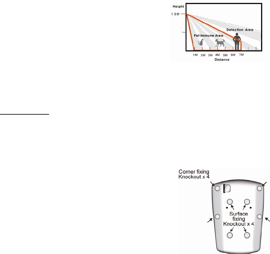
Pet Immunity (IRP-9ZBSSL Only):
Refer to diagram to the right for PIR pet immunity coverage.
If required, you can adjust the height of the PIR according
to the size of your pet for optimal pet immune performance.
Higher installation location will provide large pet-immune
space, but also increases the blind spot under the PIR.
Limitations
Do not install the PIR at location exposed direct sunlight, or
close to heating/cooling appliance and vent
Do not point the PIR at heat source such as heater, radiator
and window.
Do not point the PIR at window.
Avoid large obstacles in the detection area, and avoid moving objects such as curtain.
Avoid locations where pet may climb on and compromise pet immunity, such as stairway.
U
Us
si
in
ng
g
P
PI
IR
R
w
wi
it
th
h
Z
Zi
ig
gB
Be
ee
e
R
Ro
ou
ut
te
er
r
IMPORTANT NOTE
If PIR installation location is away from your system control panel and requires ZigBee routers to improve
signal strength. DO NOT use a ZigBee Router without backup battery. A ZigBee router without battery will
be powered down during AC power failure and the PIR connected to the router will lose connection with
ZigBee network. You should plan your PIR installation location using only ZigBee router with backup
battery.
M
Mo
ou
un
nt
ti
in
ng
g
t
th
he
e
P
PI
IR
R
Surface mounting:
1. Remove the fixing screw and cover assembly.
2. Break through the 4 wall mounting knockouts on the base.
3. Using the holes as a template, drill holes in the surface.
4. Insert the wall plugs if fixing it into plaster or brick.
5. Screw the base into the wall plugs.
6. Replace the front cover on the back cover.
Corner mounting:
1. Remove the fixing screw and cover assembly.
2. Break through the 4 corner fixing knockouts on the edge of back cover.
3. Using the corner fixing knockouts as a template, drill holes into in the corner.
4. Insert the wall plugs if fixing it into plaster or brick.
5. Screw the back cover onto the wall plugs
6. Replace the front cover on the back cover.

4
Appendix (For developers only)
P
PI
IR
R
C
Cl
lu
us
st
te
er
r
I
ID
D
Device ID: IAS Zone 0x402
Endpoint: 0x01
Server Side Client Side
Mandatory
Basic (0x0000) None
Identify(0x0003)
IAS Zone(0x0500)
Optional
None None
A
At
tt
tr
ri
ib
bu
ut
te
e
o
of
f
B
Ba
as
si
ic
c
C
Cl
lu
us
st
te
er
r
I
In
nf
fo
or
rm
ma
at
ti
io
on
n
Identifier Name Type Range Access Default
Mandatory
/ Optional
0x0000 ZCLVersion Unsigned 8-bit
integer 0x00 –0xff Read
only 0x01 M
0x0001 ApplicationVersion
Unsigned 8-bit
integer 0x00 –0xff Read
only 0x00 O
0x0003 HWVersion Unsigned 8-bit
integer 0x00 –0xff Read
only 0 O
0x0004 ManufacturerName Character
String 0 – 32 bytes Read
only Climax
Technology O
0x0005 ModelIdentifier Character
String 0 – 32 bytes Read
only (Model Version) O
0x0006 DateCode Character
String 0 – 16 bytes Read
only O
0x0007 PowerSource 8-bit 0x00 –0xff
Read
only M
0x0010 LocationDescription Character
String 0 – 32 bytes Read /
Write O
0x0011 PhysicalEnvironment 8-bit 0x00 –0xff
Read /
Write 0x00 O
0x0012 DeviceEnabled Boolean 0x00 –0x01
Read /
Write 0x01 M
A
At
tt
tr
ri
ib
bu
ut
te
e
o
of
f
I
Id
de
en
nt
ti
if
fy
y
C
Cl
lu
us
st
te
er
r
I
In
nf
fo
or
rm
ma
at
ti
io
on
n
Identifier Name Type Range Access Default
Mandatory
/ Optional
0x0000 IdentifyTime Unsigned
16-bit integer 0x00 –0xffff Read /
Write 0x0000 M
A
At
tt
tr
ri
ib
bu
ut
te
e
o
of
f
I
IA
AS
S
Z
Zo
on
ne
e
C
Cl
lu
us
st
te
er
r
I
In
nf
fo
or
rm
ma
at
ti
io
on
n
Identifier Name Type Range Access Default
Mandatory
/ Optional
0x0001 ZoneState 8-bit
Enumeration All Read
only 0x00 M
0x0002 ZoneType 8-bit
Enumeration All Read
only M
0x0003 ZoneStatus 16-bit bitmap All Read
only 0x00 M
0x0010 IAS_CIE_ADDRESS IEEE
ADDRESS Valid 64bit
IEEE address Read /
Write M
0x0011 ZONE_ID Unsigned 8-bit
integer All Read
only 0xFF M
5
Federal Communication Commission Interference Statement
This equipment has been tested and found to comply with the limits for a
Class B digital device, pursuant to Part 15 of the FCC Rules. These limits are
designed to provide reasonable protection against harmful interference in a
residential installation.
This equipment generates, uses and can radiate radio frequency energy and,
if not installed and used in accordance with the instructions, may cause
harmful interference to radio communications. However, there is no
guarantee that interference will not occur in a particular installation. If this
equipment does cause harmful interference to radio or television reception,
which can be determined by turning the equipment off and on, the user is
encouraged to try to correct the interference by one of the following
measures:
. Reorient or relocate the receiving antenna.
. Increase the separation between the equipment and receiver.
. Connect the equipment into an outlet on a circuit different from that to
which the receiver is connected.
. Consult the dealer or an experienced radio/TV technician for help.
FCC Caution
: To assure continued compliance, any changes or modifications
not expressly approved by the party responsible for compliance could void
the user's authority to operate this equipment. (Example - use only shielded
interface cables when connecting to computer or peripheral devices).
FCC Radiation Exposure Statement
This equipment complies with FCC RF radiation exposure limits set forth for
an uncontrolled environment. This equipment should be installed and
operated with a minimum distance of 0.5 centimeters between the radiator
and your body.
This transmitter must not be co-located or operating in conjunction with
any other antenna or transmitter.
The antennas used for this transmitter must be installed to provide a
separation distance of at least 0.5 cm from all persons and must not be
co-located or operating in conjunction with any other antenna or
transmitter.
This device complies with Part 15 of the FCC Rules. Operation is subject to
the following two conditions:
(1) This device may not cause harmful interference, and
(2) This device must accept any interference received,
including interference that may cause undesired
operation.