Climax Technology Co KPS Remote Keypad User Manual
Climax Technology Co Ltd Remote Keypad Users Manual
Users Manual
1
3
R
Re
em
mo
ot
te
e
K
Ke
ey
yp
pa
ad
d
(
(K
KP
P-
-1
15
5/
/
K
KP
PA
A-
-1
15
5)
)
2
21
1-
-D
DE
EC
C-
-2
20
00
09
9
z
z
I
Id
de
en
nt
ti
if
fy
yi
in
ng
g
t
th
he
e
P
Pa
ar
rt
ts
s:
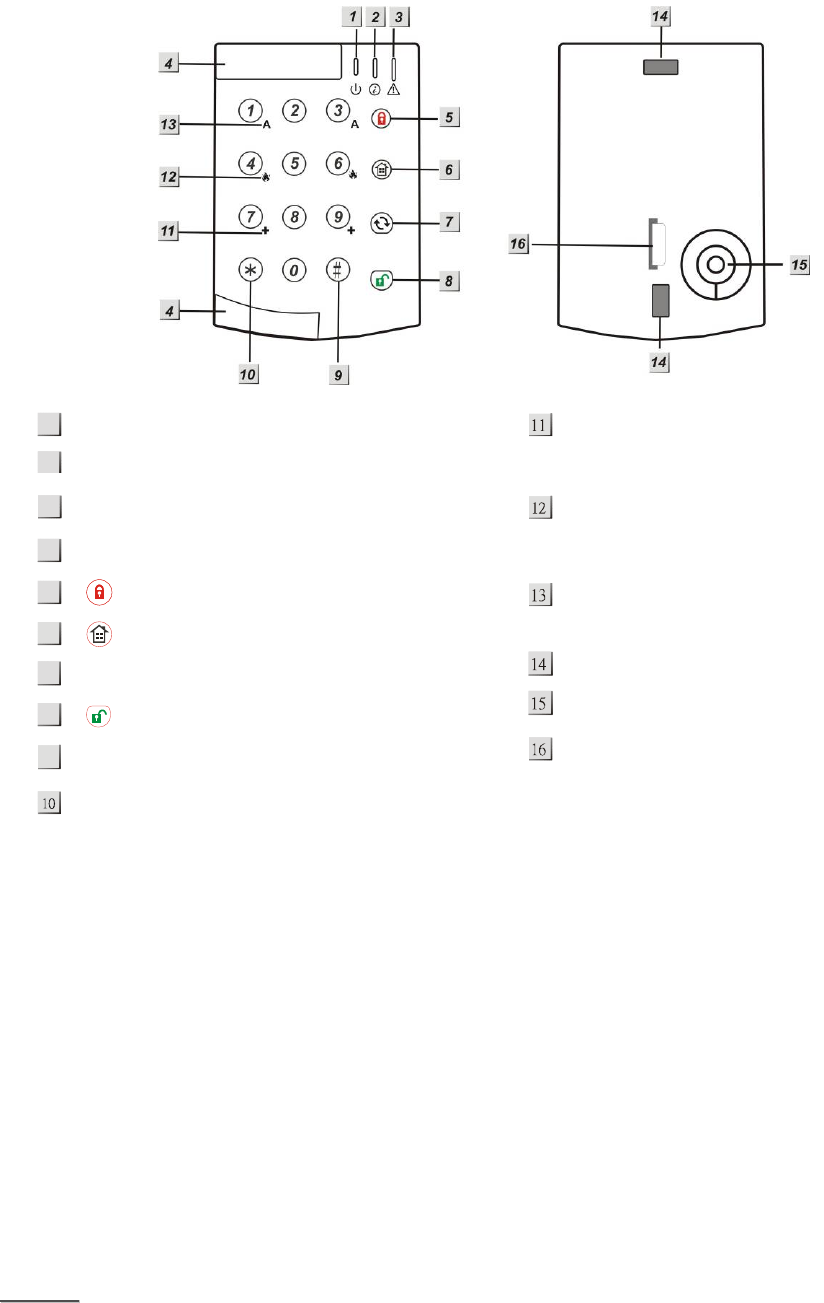
:
Green Active LED
Red TX LED
Orange Fault LED
Slide Out Section
Arm Key
Home Key
Χ Key
Disarm Key
# Key
¿ Key
+ Key
-press both 7 and 9 to trigger emergency alarm
Fire Key
-press both 4 and 6 to trigger fire alarm
A Key
-press both 1 and 3 to trigger panic alarm
Mounting Hole
Buzzer
Battery Insulator
z
z
L
LE
ED
D
I
In
nd
di
ic
ca
at
to
or
r:
:
z
z
G
Gr
re
ee
en
n
A
Ac
ct
ti
iv
ve
e
L
LE
ED
D:
:
z Green Active LED on: the system is in Normal Operation Mode.
z Green Active LED flash: the system is in Test Mode.
z When the Keypad is idle, all LEDs are off. After any key press, the G
Gr
re
ee
en
n Active LED turns on for 5
seconds indicating that Keypad is active.
z T
Th
he
e
G
Gr
re
ee
en
n Active LED will turn off after successful completion of a valid keystroke sequence or
when the pause in between key stokes is longer than 5 seconds.
z When the
G
Gr
re
ee
en
n Active LED turns off before a valid keystroke sequence is completed (5 seconds),
the previous entered keys are ignored.
z
z
R
Re
ed
d
T
TX
X
L
LE
ED
D:
:
z The Red TX LED flashes 2 times: the signal is transmitted.
z
z
O
Or
ra
an
ng
ge
e
F
Fa
au
ul
lt
t
L
LE
ED
D:
:
z Orange Fault LED flashes for 5 times: Battery is low during operation.
<
<N
NO
OT
TE
E>
>
&
&
A short beep will be sounded with each key press, which confirms valid pressing.
1
2
7
4
5
6
8
9

2
&
&
4 continuous beeps will sound indicating the user that he has entered invalid keystroke, and the user is
asked to repeat the process again.
z
z
P
Po
ow
we
er
r:
:
z The Keypad uses a CR2450 3V 540mAH lithium battery as its power source. It has a typical battery life of
over 7 years at an average of 4 activations a day.
z The Keypad can also detect the battery status. Low battery detection operates where the Keypad has
enough reserve energy to typically operate for 4 month before complete exhaustion.
z When the Keypad has low battery, the Orange
F
Fa
au
ul
lt
t LED will flash during operation and a low battery signal
will be transmitted along with regular signal transmissions.
z Before shipment, the battery is pre-installed by the factory.
z
z
P
Po
ow
we
er
r
S
Sa
av
vi
in
ng
g
F
Fe
ea
at
tu
ur
re
e:
:
z When the Keypad is not being used, no power is consumed. Whenever a key is pressed, the Keypad will
activate and “wake-up” for 5 seconds when any key is pressed.
z After 5 seconds of key inactivity, the power turns off again and returns to Stand-by mode.
z Upon completion of a command input, the power turns off and returns to Stand-by mode.
z
z
T
Te
es
st
t
m
mo
od
de
e:
:
z Keypad can be put into Test mode by entering the PIN code (default: 0000) followed by *. The Green
Active LED will flash and Keypad sounds a long beep.
z To exit Test mode, press twice, Keypad will sound a long beep and the Green Active LED will turn on,
then Keypad returns to Normal Operation mode.
<
<N
NO
OT
TE
E>
>
&
&
When Keypad is in Test mode, it operates as wake-up condition thus will NOT disconnect after 5 seconds.
&
&
In Test Mode, if no key is pressed within 30 minutes, the Keypadl will automatically exit Test Mode to
Normal Operation mode.
The Keypad Test mode enables the following functions:
Transmit Keypad learn signal — press * and then 1
Dual-key Panic Alarm Enable — press * and then 2
Dual-key Fire Alarm Enable — press * and then 3
Dual-key Medical Alarm Enable — press * and then 4
Change the Pin Code — press * and then 6
Enter Old Pin Code and then press Χ
Enter New 4-digit Pin Code and then press #
Dual Key Disable — Press * and then 5
Quit Test Mode —press twice.
Arm/ Home without PIN Code — press * and then 8
Arm/ Home with PIN Code — press * and then 9
<
<N
NO
OT
TE
E>
>
&
&
For wrong entering or operating the Keypad will sound 4 short beeps.
&
&
When the Pin Code is wrong entered for 4 times, the Keypad will sound 4 beeps and all LED flash 4 times.
The Keypad will be locked for 1 min. After 1 minute, the Keypad will sound one beep and can be used
again.

3
z
z
I
In
ns
st
ta
al
ll
la
at
ti
io
on
n
P
Pr
ro
oc
ce
ed
du
ur
re
es
s:
:
Step 1. Put Keypad in Test mode by entering “0000” (default PIN code), then press *. Keypad will sound 1
long beep and the Green Active LED will steadily flash.
Step 2. Adding Keypad into the Control Panel:
I. Put the Control panel into Device +/- menu and select the Add Devices sub menu.
II. Press * and then 1 when requested. Keypad and Control Panel will beep once.
III. Refer to the operation manual of your control Panel under the section of Device +/- to complete
the learn-in process.
Step 3. After the Keypad is learnt-in, put the Control Panel into Walk Test mode, hold the Keypad in the
desired location, press the * then 1 button to confirm this location is within signal range of the
Control Panel.
Step 4. When you are satisfied that the Keypad works in the chosen location, you can proceed with mounting
the Keypad following the steps described below (see Mounting Keypad).
Step 5. Setting the Pin Code:
I. Press * then 6, a long beep will be sound.
II. Enter 0000 (default PIN code)
III. PressΧ, Keypad sounds a long beep.
IV. Enter your new 4-digit code.
V. Press #, Keypad sounds a long beep.
Step 6. Press twice to exit Test mode and the installation is completed.
z
z
M
Mo
ou
un
nt
ti
in
ng
g
t
th
he
e
K
Ke
ey
yp
pa
ad
d:
:
To mount the Keypad:
I. Remove the 2 slide-out sections of front cover.
II. Using the 2 mounting holes as a template, mark off the positions in the most appropriate place.
III. Insert the wall plugs if fixing into plaster or brick surface.
IV. Screw the Keypad onto the wall plugs.
V. Replace the 2 slide-out sections.
z
z
H
Ho
ow
w
t
to
o
S
Se
et
t
S
Sy
ys
st
te
em
m
M
Mo
od
de
e:
:
Arm/Home with Pin Code
¾ Arm Mode: Enter anyone of Control Panel user codes and press key. Red TX LED will flash 5
times and the Keypad sounds a long beep.
¾ Home Mode: Enter anyone of Control Panel user codes and press key. Red TX LED will flash 5
times and the Keypad sounds 3 beeps.
¾ Disarm Mode: Enter anyone of Control Panel user codes and press key. Red TX LED will flash 5
times and the Keypad sounds 2 beeps.
¾ Enter Test Mode — Enter Keypad PIN code and press * key. The Keypad will sound 1 long beep and
Green Active LED flashes steadily.
¾ Panic Alarm — Press 1 + 3 simultaneously at the same time. Red TX LED will flash 5 times and the
Keypad sounds a long beep.
¾ Fire Alarm — Press 4 + 6 simultaneously at the same time. Red TX LED will flash 5 times and the
Keypad sounds a long beep.
¾ Medical Alarm — Press 7 + 9 simultaneously at the same time. Red TX LED will flash 5 times and the
Keypad sounds a long beep.
¾ For wrong entering or operating the Keypad will sound 4 short beeps.
Arm/ Home without PIN Code
¾ Arm Mode: Press key. Red TX LED will flash 5 times and the Keypad sounds a long beep.
¾ Home Mode: Press key. Red TX LED will flash 5 times and the Keypad sounds 3 beeps.
¾ Disarm Mode: Enter anyone of Control Panel user codes and Key. Red TX LED will flash 5 times
and the Keypad sounds 2 beeps.

4
¾ Enter Test Mode — Enter Keypad PIN code and press * key. The Keypad will sound 1 long beep and
Green Active LED flashes steadily.
¾ Panic Alarm — Press 1 + 3 simultaneously at the same time. Red TX LED will flash 5 times and the
Keypad sounds a long beep.
¾ Fire Alarm — Press 4 + 6 simultaneously at the same time. Red TX LED will flash 5 times and the
Keypad sounds a long beep.
¾ Medical Alarm — Press 7 + 9 simultaneously at the same time. Red TX LED will flash 5 times and the
Keypad sounds a long beep.
¾ For wrong entering or operating the Keypad will sound 4 short beeps.
z
z
C
Ch
ha
an
ng
ge
e
o
of
f
B
Ba
at
tt
te
er
ry
y:
:
I. Put the Control Panel to programming menu.
II. Dismount the Keypad by first removing the slide-out sections then the mounting screws.
III. Open the Keypad by loosening the 2 fixing screw located behind the Keypad
IV. Take out the old battery and wait for 5 minutes before replacing the new battery in the battery
compartment, with unmarked (negative) side of battery facing down.
V. Close the case using the rear fixing screws.
VI. Screw back the Keypad to the surface with mounting screws, and then re-insert the slide-outs.
VII. Put the Control Panel to exit Programming Menu.
z
z
A
Ap
pp
pe
en
nd
di
ix
x:
:
If you have forgotten the Pin Code or anything wrong happened in the Keypad, you can reset the Keypad to
factory default and reinitialize it.
Reset to factory default:
Step 1 Remove one of the batteries
Step 2 Press 3 while inserting the removed battery back in
Step 3 Continue pressing 3 until 3 short beeps to indicate successful reset
Step 4 Release 3
<
<N
NO
OT
TE
E>
>
&
&
After reset, PIN code reverts to factory default values, “0000”. Keypad will need a new learn-in process
to start functioning.
5
Federal Communication Commission Interference Statement
This equipment has been tested and found to comply with the limits for a Class B digital device, pursuant to Part 15
of the FCC Rules. These limits are designed to provide reasonable protection against harmful interference in a
residential installation.
This equipment generates uses and can radiate radio frequency energy and, if not installed and used in accordance
with the instructions, may cause harmful interference to radio communications. However, there is no guarantee that
interference will not occur in a particular installation. If this equipment does cause harmful interference to radio or
television reception, which can be determined by turning the equipment off and on, the user is encouraged to try to
correct the interference by one of the following measures:
. Reorient or relocate the receiving antenna.
. Increase the separation between the equipment and receiver.
. Connect the equipment into an outlet on a circuit different from that to which the receiver is connected.
. Consult the dealer or an experienced radio/TV technician for help.
FCC Caution:
To assure continued compliance, any changes or modifications not expressly approved by the party responsible for
compliance could void the user's authority to operate this equipment. (Example - use only shielded interface cables
when connecting to computer or peripheral devices).