Climax Technology Co LS Light Switch User Manual LS 1ZBS R Series 20151117
Climax Technology Co Ltd Light Switch LS 1ZBS R Series 20151117
Users Manual
1
ZigBee Light Switch: LS-1-ZBS(R) Series
Introduction
LS-1-ZBS(R) ZigBee Light Switch series include Master Light Switch and Slave Light Switch models.
Depending on the models selected, the light switch can be deployed in single or 3-way installation
according to requirement.
The Light Switch package is designed to be used in new installations or replace existing 3-way light
switch to achieve home automation. After joining ZigBee network, the Light Switch package can be
controlled via ZigBee network to activate remotely turn on/off household lighting.
The Master Light Switch utilizes ZigBee technology for wireless signal transmission. ZigBee is a
wireless communication protocol that is reliable, has low power consumption and has high transmission
efficiency. Based on the IEEE802.15.4 standard, ZigBee allows a large amount of devices to be
included in a network and coordinated for data exchange and signal transmission.
The Master Light Switch can also be bound to a ZigBee Controller to toggle On/Off the connected
lighting.
Models with router function (LS-1A-G-ZBSR and LS-1E-G-ZBSR) also serve as a router in the ZigBee
network. After being included in the ZigBee network, it allows other ZigBee device to join the network
through the Light Switch.
Caution
The devices are intended for installation in accordance with the local wiring regulations such as the
National Electric Code in the United States, the Canadian Electrical Code, or CSA C22.1, etc.. If you are
unsure or uncomfortable about installing this device, please consult a qualified electrician in your area.
Parts Identification
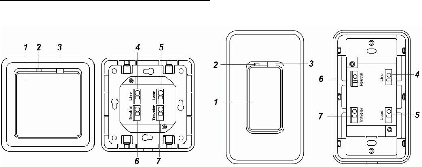
Master Light Switch: LS-1A/E-G-ZBS(R)
LS-1E-G-ZBS(R) LS-1A-G-ZBS®
1. Function Button
- Pressing the button to toggle on/off the switch.
- Press and hold the button for 10 seconds then release to reset the Light Switch.
- Press and hold the button for 3 seconds then release to bind with a controller
2. LED indicator
The LED indicator is used to indicate Light Switch status:
- On:
The Light Switch is turned off.
- Off:
The Light Switch is turned on.
- Flashes twice:
The Light Switch has successfully joined a ZigBee network.
- Flashes five times
The Light Switch has successfully bound with a controller
- Flashes every 20 minutes
2
The Light Switch has lost connection to its current ZigBee network (LS-1A-G-ZBS /
LS-1E-G-ZBS only)
- Flashing continuously
The Light Switch is overheated.
3. Air Gap Switch
- Pulled out:
Completely removes the power available to the load. This enables the connected lighting (bulb,
tube, etc.) that is controlled by the light switch to be changed with minimal danger of electrical
shock.
Use a flat-head screwdriver to pull the switch out.
- Pushed in:
For normal operation of the light switch.
Connection Terminals
Insert a flat-head screwdriver to open the clipper for each terminal and connect wiring. Remove the
screwdriver to close the clipper and hold wire in place.
4. Line Terminal
5. Load Terminal
6. Neutral Terminal
7. Travel Terminal
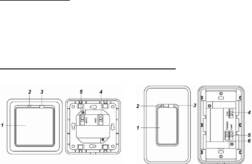
Master Light Switch: LS-1A/E-B (Rechargeable Battery)
LS-1E-B-ZBS LS-1A-B-ZBS
1. Function Button
- Pressing the button to toggle on/off the switch.
- Press and hold the button for 10 seconds then release to reset the Light Switch.
- Press and hold the button for 3 seconds then release to bind with a controller
2. LED indicator
The LED indicator is used to indicate Light Switch status:
- On:
The Light Switch is turned off.
- Off:
The Light Switch is turned on.
- Flashes twice:
The Light Switch has successfully joined a ZigBee network.
- Flashes five times
The Light Switch has successfully bound with a controller
- Flashes every 20 minutes
The Light Switch has lost connection to its current ZigBee network (LS-1A-B-ZBS only)
3. Air Gap Switch
- Pulled out:
3
Completely removes the power available to the load and charges the rechargeable battery of the
Light Switch. This enables the connected lighting (bulb, tube, etc.) that is controlled by the light
switch to be changed with minimal danger of electrical shock.
For the first time installation of LS-1A-B Light Switch, Air Gap Switch must be pulled out to
charge the rechargeable battery of the Light Switch.
Use a flat-head screwdriver to pull the switch out.
- Pushed in:
For normal operation of the light switch.
Connection Terminals
Insert a flat-head screwdriver to open the clipper for each terminal and connect wiring. Remove the
screwdriver to close the clipper and hold wire in place.
4. Line Terminal
5. Load Terminal
6. Travel Terminal (LS-1A-B-ZBS Only)
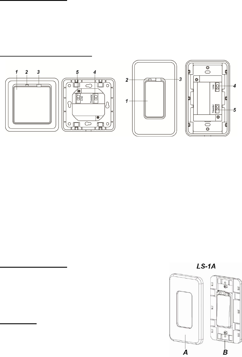
Slave Light Switch: LS-1A/E-S
1. Switch Button
- Pressing the button to toggle on/off the connected lighting.
2. LED indicator
The LED indicator is used to indicate Light Switch status:
- On:
The Light Switch is turned off.
- Off:
The Light Switch is turned on.
3. Air Gap Switch
- Pulled out:
Completely removes the power available to the load. This enables the connected lighting (bulb,
tube, etc.) that is controlled by the light switch to be changed with minimal danger of electrical
shock.
Use a flat-head screwdriver to pull the switch out.
- Pushed in:
For normal operation of the light switch.
Connection Terminals
Insert a minus screwdriver to open the clipper for each terminal
and connect wiring. Remove the screwdriver to close the clipper
and hold wire in place.
4. Line Terminal
5. Travel Terminal
Front Cover
A. Switch Cover
B. Light Switch Base
4
Installation
W
Wi
ir
ri
in
ng
g
The insertion holes’ wiring specification is AWG 14-24 or Ø 2.08-0.205 (mm ).
Please make sure the main power is switched off (to prevent electrical shock). It is also
recommended that you have an electrical tester to test whether the wires are hot or not.
If applicable, remove the previously installed Light Switch first.
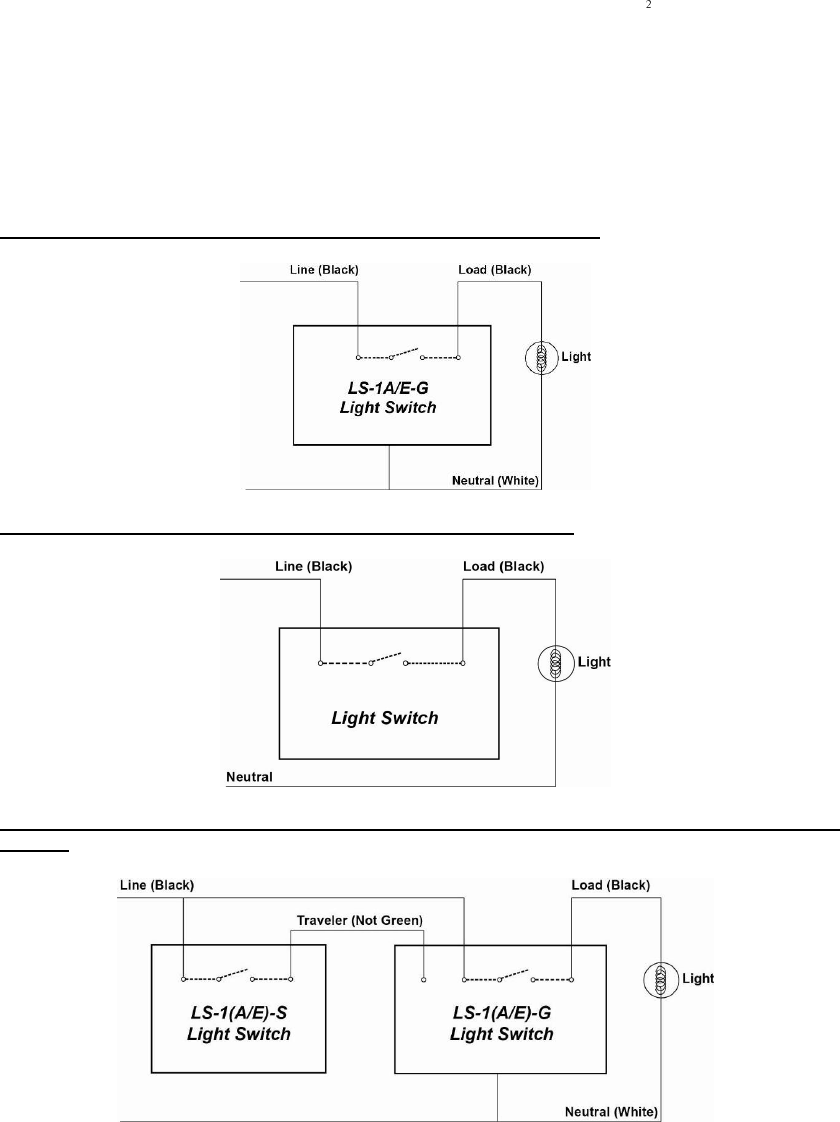
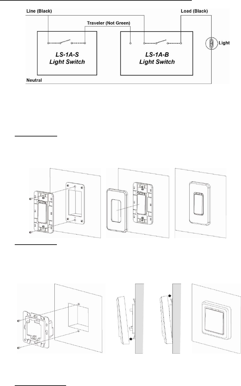
Follow the schematics below to wire the Light Switch according to the desired installation.
To connect the wires, insert a flat-head screwdriver to open the clipper for each terminal and
connect wiring. Remove the screwdriver to close the clipper and hold wire in place.
Please note that the wiring color below are for references only, consult an electrician if you have
trouble identifying the terminals of the desired wiring circuit or if you do not feel confident to convert
the circuit.
Single Switch Wiring (One Switch, One Load) using LS-1A/E-G-ZBS(R)
Single Switch Wiring (One Switch, One Load) using LS-1A/E-B-ZBS
3-Way Wiring (Two Switches, One Load) using LS-1A-G-ZBS and LS-1A-S or LS-1E-G-ZBS and
LS-1E-S
5
3-Way Wiring (Two Switches, One Load) using LS-1A-B-ZBS and LS-1A-S
M
Mo
ou
un
nt
ti
in
ng
g
After connecting the wires, follow the steps below to mount the Light Switch on the wall.
Usually, the wires are freely exposed (before connected) inside the hole of the wall. For some
configurations, there is a box inside where the wires can be placed.
The wall or box may also have one top screw hole and one bottom screw hole.
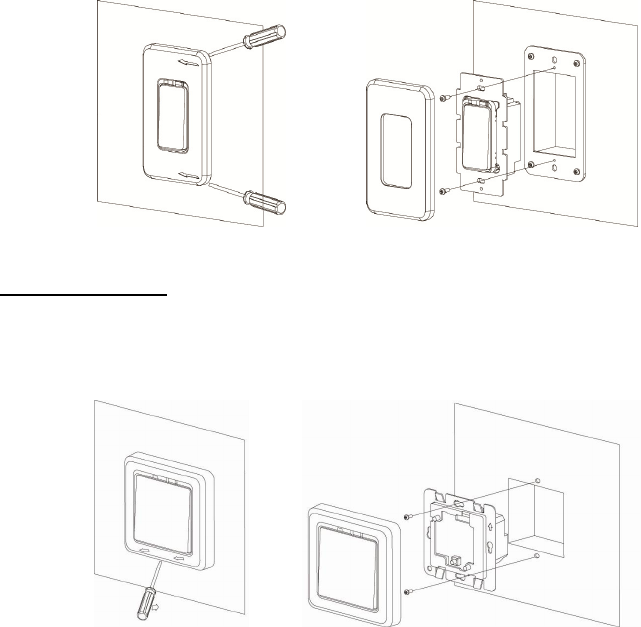
LS-1A Mounting
1. Insert the Light Switch Base into the hole (or box) in the wall and tighten the top and bottom
screws using a Philips screwdriver as shown in diagram 1.
2. Push the Switch Cover onto the Light Switch as shown in diagram 2. If the Switch Cover is
stabilized onto the switch, you should hear a Click sound.
3. Mounting is complete. Turn the main power back on to test the switch.
LS-1E Mounting
1. Insert the Light Switch Base into the hole (or box) in the wall and tighten the top and bottom
screws using a Philips screwdriver
2. Slide the Switch Cover from the bottom towards the Base to stabilize the Light Switch.
3. Push the Switch Cover onto the Light Switch Base. If the Switch Cover is stabilized onto the
switch, you should hear a Click sound.
4. Mounting is complete. Turn the main power back on to test the switch.
D
Di
is
sm
mo
ou
un
nt
ti
in
ng
g
Follow the steps below to dismount the Light Switch:
Please make sure the main power is switched off.
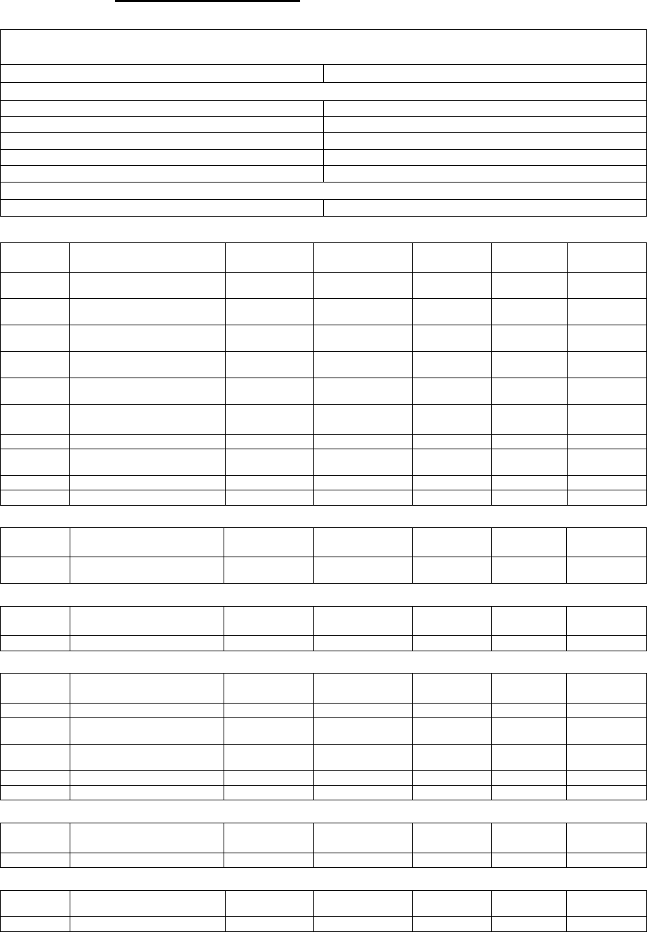
LS-1A Dismounting
1. Insert a flat-head screwdriver to one corner of the Switch Cover and lift the Switch Cover.
2. Insert a flat-head screwdriver to another corner of the Switch Cover and lift the Switch Cover.
3. Lift the Switch Cover gently from the lifted side.
4. Lift the Switch Cover completely.
6
5. Loosen the top and bottom screws using a Philips screwdriver and remove the Light Switch
Base.
LS-1A Dismounting
1. Insert a flat-head screwdriver to the caved in area of the Switch Cover and carefully lift the
Switch Cover.
2. Slide the Switch Cover downwardly from the Base to remove the Switch Cover completely.
3. Loosen the top and bottom screws using a Philips screwdriver and remove the Light Switch
Base.
ZigBee Network Setup (Master Switch only)
Z
Zi
ig
gB
Be
ee
e
D
De
ev
vi
ic
ce
e
G
Gu
ui
id
de
el
li
in
ne
e
ZigBee is a wireless communication protocol that is reliable, has low power consumption and has
high transmission efficiency. Based on the IEEE802.15.4 standard, ZigBee allows a large amount
of devices to be included in a network and are coordinated for data exchange and signal
transmission.
J
Jo
oi
in
ni
in
ng
g
t
th
he
e
Z
Zi
ig
gB
Be
ee
e
N
Ne
et
tw
wo
or
rk
k
As a ZigBee device, the Master Light Switch needs to join a ZigBee network to receive commands.
Please follow the steps bellow to join the Light Switch into a ZigBee network.
1. Connect power to the Light Switch according to Installation instruction above.
2. Press and hold the function button for 10 seconds as the Light Switch resets and starts
searching for existing ZigBee network. Please make sure the permit-to-join feature on the
router or coordinator of your ZigBee network is enabled.
3. If the Light Switch successfully joins a ZigBee network, the LED Indicator will flash twice.
4. After joining the ZigBee network, the Light Switch will be registered in the network
automatically. Please check the ZigBee network coordinator, system control panel or CIE
(Control and Indicating Equipment) to confirm if joining and registration is successful.
5. After joining the ZigBee network, if the Light Switch loses connection to the current ZigBee
network, the LED indicator will flash every 20 minutes. Please check your ZigBee network
condition and Light Switch signal range to correct the condition.
B
Bi
in
nd
di
in
ng
g
w
wi
it
th
h
C
Co
on
nt
tr
ro
ol
ll
le
er
r
After joining the ZigBee network, the Master Light Switch can bind itself with a controller device
which can be used to toggle on/off the connected lighting. To bind the Light Switch and the device:
1. Press and hold the Function Button for 3 seconds, then release the button. The Light Switch
will send binding request to the coordinator.
2. Refer to your controller manual to send binding request for the device within 16 seconds.
3. If binding is successful, the Light Switch LED indicator will flash 5 times to confirm. You can
now use the controller to toggle on/off the connected lighting.
7
F
Fa
ac
ct
to
or
ry
y
R
Re
es
se
et
t
If you want to remove the Light Switch from current network and join a new network, you need to
use the Factory Reset function to clear the Light Switch from its stored setting and information first
before it can join another network. To perform Factory Reset:
1. Press and hold the switch button for 10 seconds, release the button when the LED Indicator
flashes once.
2. The Light Switch has been reset to factory default setting with all its previous network
information removed. It will now actively search for available ZigBee network again and join the
network automatically.
3. If the Light Switch successfully joins a ZigBee network, the LED Indicator will flash twice to
indicate.
Z
Zi
ig
gB
Be
ee
e
R
Ro
ou
ut
te
er
r
D
De
ev
vi
ic
ce
e
C
Ca
ap
pa
ac
ci
it
ty
y
(
(L
LS
S-
-1
1A
A-
-G
G-
-Z
ZB
BS
SR
R
/
/
L
LS
S-
-1
1E
E-
-G
G-
-Z
ZB
BS
SR
R
O
On
nl
ly
y)
)
The Light Switch models with Router function (LS-1A-G-ZBSR / LS-1E-G-ZBSR) allow other
ZigBee devices to join the ZigBee Network through the Router. The Light Switch Router has a
maximum capacity of 40 devices/routers.
Features
P
Po
ow
we
er
r
S
Su
up
pp
pl
ly
y
LS-1A/E-G-ZBS(R): The Light Switch is powered by the AC connections.
LS-1A/R-B-ZBS: The Light Switch uses a rechargeable battery pack as its main power source.
When the Light Switch is turned on, the Light Switch is powered by the rechargeable battery pack.
Whenever the Light Switch is turned off or when the Air Gap Switch is pulled out, AC connection
will start charging the battery pack. For the initial setup of LS-1A-B, please pull the Air Gap Switch
out (using a flat-head screwdriver) and charge its rechargeable battery for at least 30 minutes.
Please make sure Line, Load and the light bulb (or tube) are fully connected to ensure the battery
is being charged.
L
Lo
ow
w
B
Ba
at
tt
te
er
ry
y
D
De
et
te
ec
ct
ti
io
on
n
(
(L
LS
S-
-1
1A
A/
/E
E-
-B
B-
-Z
ZB
BS
S
o
on
nl
ly
y)
)
When the Light Switch is low on battery, it will transmit low battery signal along with the
supervision signal to the ZigBee network coordinator or control panel to warn the user(s).
S
Su
up
pe
er
rv
vi
is
si
io
on
n
T
he Light Switch will transmit a supervision signal to report its condition regularly every 30 minutes.
The user can also press the Function Button once to transmit a supervision signal manually.
Operation
L
Li
ig
gh
ht
t
S
Sw
wi
it
tc
ch
h
C
Co
on
nt
tr
ro
ol
l
After the Master Light Switch has successfully joined a ZigBee network, the
coordinator/control panel can remotely control the Light Switch to toggle the connected
lighting between On and Off. Please refer to your ZigBee coordinator/control panel for detail.
You can also press the button on the Light Switch to toggle on/off the connected lighting.
If you have bound a controller with the Light Switch, you can also use the controller to turn
on/off the connected lighting.
If there is a power shortage (e.g. wiring disconnected), its previous on/off status will be
restored within 1 minute after the power is restored.
M
Ma
ax
xi
im
mu
um
m
O
Op
pe
er
ra
at
ti
io
on
n
L
Lo
oa
ad
d
The Master Light Switch has a maximum capacity of 5A.
If the LS-1A-G-ZBS or LS-1E-G-ZBS(R) Light Switch is overheated, the circuit will cut off
automatically as the connected lighting will turn off. The LED will start to flash.
During the overheated period, users cannot switch the light on (whether controlled by the
ZigBee coordinator, controller or pressing the function button).
The LED will stop flashing when the Light Switch returns to normal operation condition. The
Light Switch can then be turned on again.
A fuse is installed in the LS-1A/E-B-ZBS Light Switch to protect from the harmful effects of
over-currents. The fuse will blow if the connection causes an over-current.
8
Appendix
(For developers only)
L
Li
ig
gh
ht
t
S
Sw
wi
it
tc
ch
h
C
Cl
lu
us
st
te
er
r
I
ID
D
Device ID: Mains Power Outlet :0x0009
Endpoint:0x0A
Server Side Client Side
Mandatory
Basic (0x0000) None
Identify(0x0003)
Groups(0x0004)
Scenes(0x0005)
On/Off(0x0006)
Optional
Power Configuration(0x0001) (LS-1A-B only) None
A
At
tt
tr
ri
ib
bu
ut
te
e
o
of
f
B
Ba
as
si
ic
c
C
Cl
lu
us
st
te
er
r
I
In
nf
fo
or
rm
ma
at
ti
io
on
n
Identifier
Name Type Range Access Default
Mandatory
/ Optional
0x0000 ZCLVersion Unsigned 8-bit
integer 0x00 –0xff Read only 0x01 M
0x0001 ApplicationVersion Unsigned 8-bit
integer 0x00 – 0xff Read only 0x00 O
0x0003 HWVersion Unsigned 8-bit
integer 0x00 –0xff Read only 0 O
0x0004 ManufacturerName Character
String 0 – 32 bytes Read only Climax
Technology
O
0x0005 ModelIdentifier Character
String 0 – 32 bytes Read only (Model
Version) O
0x0006 DateCode Character
String 0 – 16 bytes Read only O
0x0007 PowerSource 8-bit 0x00 –0xff Read only M
0x0010 LocationDescription Character
String 0 – 32 bytes Read / Write
O
0x0011 PhysicalEnvironment 8-bit 0x00 –0xff Read / Write
0x00 O
0x0012 DeviceEnabled Boolean 0x00 –0x01 Read / Write
0x01 M
A
At
tt
tr
ri
ib
bu
ut
te
e
o
of
f
I
Id
de
en
nt
ti
if
fy
y
C
Cl
lu
us
st
te
er
r
I
In
nf
fo
or
rm
ma
at
ti
io
on
n
Identifier
Name Type Range Access Default
Mandatory
/ Optional
0x0000 IdentifyTime Unsigned
16-bit integer
0x00 –0xffff Read / Write
0x0000 M
A
At
tt
tr
ri
ib
bu
ut
te
es
s
o
of
f
t
th
he
e
G
Gr
ro
ou
up
ps
s
c
cl
lu
us
st
te
er
r
I
In
nf
fo
or
rm
ma
at
ti
io
on
n
Identifier
Name Type Range Access Default
Mandatory
/ Optional
0x0000 NameSupport 8-bit bitmap x0000000 Read only - M
A
At
tt
tr
ri
ib
bu
ut
te
es
s
o
of
f
t
th
he
e
S
Sc
ce
en
ne
es
s
c
cl
lu
us
st
te
er
r
I
In
nf
fo
or
rm
ma
at
ti
io
on
n
Identifier
Name Type Range Access Default
Manda
tory
/ Optional
0x0000 NameSupport 8-bit bitmap x0000000 Read only 0x00 M
0x0001 CurrentScene Unsigned 8-bit
integer 0x00 – 0xff Read only 0x00 M
0x0002 CurrentGroup Unsigned
16-bit Integer
0x0000 – 0xfff7
Read only 0x00 M
0x0003 SceneValid Boolean 0x00 – 0x01 Read only 0x00 M
0x0004 NameSupport 8-bit bitmap x0000000 Read only - M
A
At
tt
tr
ri
ib
bu
ut
te
e
o
of
f
O
On
n/
/O
Of
ff
f
C
Cl
lu
us
st
te
er
r
I
In
nf
fo
or
rm
ma
at
ti
io
on
n
Identifier
Name Type Range Access Default
Mandatory
/ Optional
0x0000 OnOff Boolean 0x00 –0x01 Read only 0x00 M
A
At
tt
tr
ri
ib
bu
ut
te
e
o
of
f
P
Po
ow
we
er
r
C
Co
on
nf
fi
ig
gu
ur
ra
at
ti
io
on
n
C
Cl
lu
us
st
te
er
r
I
In
nf
fo
or
rm
ma
at
ti
io
on
n
(
(L
LS
S-
-1
1A
A-
-B
B
o
on
nl
ly
y)
)
Identifier
Name Type Range Access Default
Mandatory /
Optional
0x0035 BatteryAlarmMask Bitmap 0 Read / Write
0 O
9
Federal Communication Commission Interference Statement
This equipment has been tested and found to comply with the limits
for a Class B digital device, pursuant to Part 15 of the FCC Rules.
These limits are designed to provide reasonable protection against
harmful interference in a residential installation.
This equipment generates uses and can radiate radio frequency energy
and, if not installed and used in accordance with the instructions, may
cause harmful interference to radio communications. However, there is
no guarantee that interference will not occur in a particular installation.
If this equipment does cause harmful interference to radio or
television reception, which can be determined by turning the
equipment off and on, the user is encouraged to try to correct the
interference by one of the following measures:
. Reorient or relocate the receiving antenna.
. Increase the separation between the equipment and receiver.
. Connect the equipment into an outlet on a circuit different from that
to which the receiver is connected.
. Consult the dealer or an experienced radio/TV technician for help.
FCC Caution
FCC CautionFCC Caution
FCC Caution
: To assure continued compliance, any changes or
modifications not expressly approved by the party responsible for
compliance could void the user's authority to operate this equipment.
(Example - use only shielded interface cables when connecting to
computer or peripheral devices).
FCC Radiation Exposure Statement
FCC Radiation Exposure StatementFCC Radiation Exposure Statement
FCC Radiation Exposure Statement
This equipment complies with FCC RF radiation exposure limits set
forth for an uncontrolled environment. This equipment should be
installed and operated with a minimum distance of 20 centimeters
between the radiator and your body.
This transmitter must not be co-located or operating in conjunction
with any other antenna or transmitter.
The antennas used for this transmitter must be installed to provide a
separation distance of at least 20 cm from all persons and must not be
co-located or operating in conjunction with any other antenna or
transmitter.
This device complies with Part 15 of the FCC Rules. Operation is
subject to the following two conditions:
(1) This device may not cause harmful interference, and
(2) This device must accept any interference received, including
interference that may cause undesired operation.