Climax Technology Co LT Locator User Manual
Climax Technology Co Ltd Locator Users Manual
Users Manual
1
INSTALLATION GUIDE
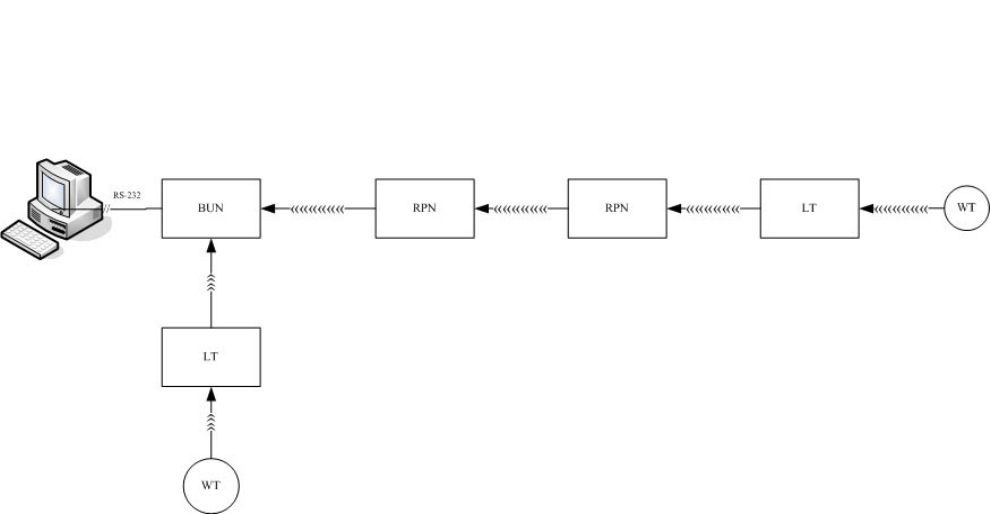
z SYSTEM CONFIGURATION
Locator (LT-49): It is used for receiving 433 MZH device signal and transmit it in 912
MHZ to Repeater (RPN-99) or Base Unit (BUN-152).
Repeater (RPN-99): It is used to relay whatever signal received with same Group number
and System ID in 912 MHZ.
Base Unit (BUN-152): To receive the signals from LT-49 and RPN-99 in 912 MHZ.
z SYSTEM CAPIBILITY:
z Each system can have maximum of 4096 LT-49 and 4096 RPN-99.
z Each Locator and Repeater has its own ID Code set by a 12-pin Dip Switch.
z The frequency hopping technology is adopted in the communication between
Locator, Repeater and BUN-152.
z There are three groups of hopping frequency bands are available. Each group
contains 25 channels:
GROUP 1: 906.26 ~ 914.90 MHZ, 25 channels
GROUP 2: 906.38 ~ 915.02 MHZ, 25 channels
GROUP 3: 906.50 ~ 915.14 MHZ, 25 channels
26-APR.-2005
2
BUN-152
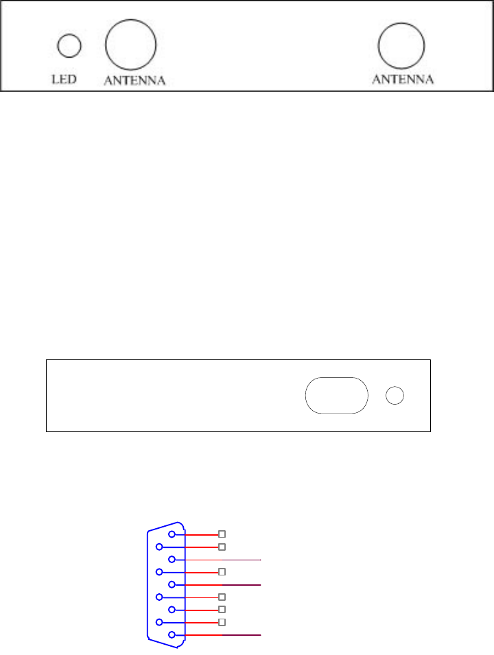
z Front View of BUN-152:
LED:
— When the Power is ON, the LED will stays on. It flashes moment when either
RPN-99 or LT-49’s signal has been received.
ANTENNA connector (TNC connector):
— It has two connectors for Antenna. During the installation, be sure to put both
Antennas upwards and then screw it towards the TNC connector.
z Rear View:
DC JACK: For connecting to 12V 500mA Power Adaptor
RS-232 CONNECTOR: Connects the RS-232 cable to PC.
Pin2: TXD
Pin3: RXD
Pin5: GOUND
Pin 1,4,5,6,7,8,9 : No Connection.
DC JACKRS-232
5
9
4
8
3
7
2
6
1
TXD
RXD
GND
3
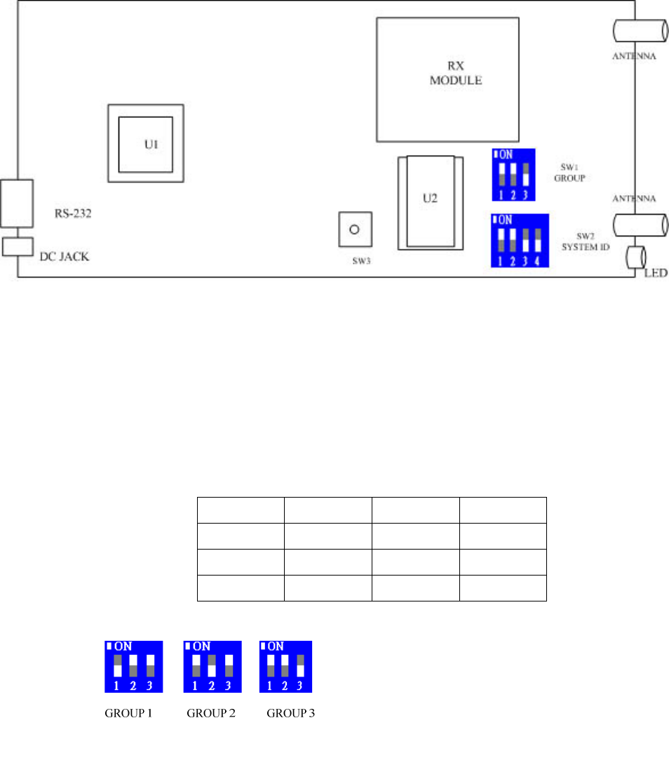
z Interior View:
SW1: It is used for setting the number of Groups. There are 3 Groups for use with
its own frequency band.
SW1: The SW1 switch block contains 3 dip switches. Slide the SW1 up (On
position) with SW2 & SW3 down (Off position), to select Group1 frequency
band. Likewise, slide SW2 or SW3 up (On) with others, down (Off), Group2
or Group3 is selected accordingly.
SW1 SW2 SW3 Group
On Off Off Group1
Off On Off Group2
Off Off On Group3
GROUP 1 frequency: 906.26 ~ 914.90 MHZ, 25 channels with spacing of
360KHZ between each channel.
GROUP 2 frequency: 906.38 ~ 915.02 MHZ, with spacing of 360KHZ
between each channel.
GROUP 3 frequency: 906.50 ~ 915.14 MHZ, with spacing of 360KHZ
between each channel.
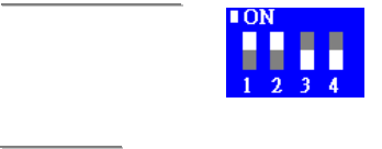
SW2: For setting the system ID code, there are total of 16 SYSTEM ID
combinations for use from 0 to 15.
4
<
<E
EX
XA
AM
MP
PL
LE
E>
>
System ID = 3
<
<N
NO
OT
TE
E>
>
) Remember to set BUN-152’s “Group” and “System ID” identical with
RPN-99 and LT-49’s setting in order for them to communicate between
each other.
5
RPN-99
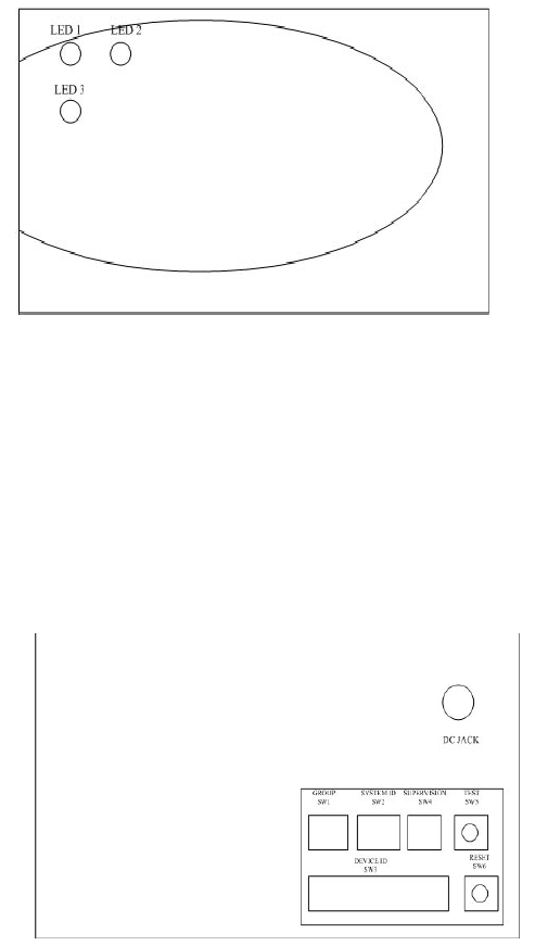
z Front View of RPN-99:
LED 1: It is a dual-color LED, Green and
Red.
When the AC Power is ON, the
Green LED will stays on. If no
AC Power is connected and only
Battery is used for main power
source, then, the Green LED will
flash continuously.
If the Low Battery is detected,
the Red LED will stays on to warn the user for changing Power source.
LED 2: The Red LED will flash once when the RPN-99 receives a signal from other
RPN-99 or LT-49.
LED 3: The Red LED will flash once when the RPN-99 transmits its signal.
z Rear View (with Lid removed):
DC JACK: For connecting DC 12V 800 mA Power Adaptor.
SW1 : For setting the Group number,
please refer to the section
“BUN-152”. Make sure each unit
in a system should have the same
Group number.
SW2 : For setting the system ID code,
please refer to the section
“BUN-152”. Make sure each unit
in a system should have the same
system ID.
SW 3 : A 12-pin dip switch block to set the
“Unit ID Number”.
Each RPN-99 should be assigned an unique ID Number; so that the BUN-152 can
distinguish the signal received is from which RPN-99.
There are a total of 212 = 4096 combinations for a maximum of 4096 RPN-99’s to be
used in one system.
6
<
<E
EX
XA
AM
MP
PL
LE
E>
>
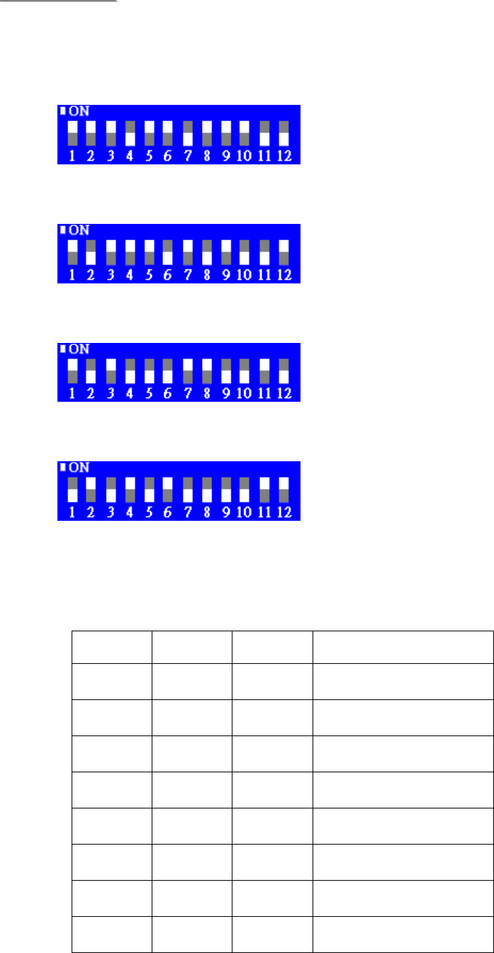
The following examples show you how the “Unit ID” is set (B represents for
Binary, H for Hex and the last numbers represents for Decimal):
UP=1 , DOWN =0
UNIT ID=000100100011B=0123H = 291
UNIT ID=010001010110B=0456H = 1110
UNIT ID=010111001101B=05CDH = 1485
UNIT ID=101010111100B=0ABCH = 2748
SW4: A 3-pin dip switch block to set the “supervision period”. 8 options are
available as shown in table below:
SW1 SW2 SW3 Supervision Period
Off Off Off Disable
Off Off On 1 hour
Off On Off 2 hours
Off On On 3 hours
On Off Off 4 hours
On Off On 8 hours
On On Off 10 hours
On On On 12 hours

7
<
<E
EX
XA
AM
MP
PL
LE
E>
>
If a 2-hour supervision period is set (SW1-off, SW2-On, SW3-off), the
RPN-99 will send the “supervision” signal every 2 hours.
SW 5 : TEST button.
When it is pressed, RPN-99 will automatically sends out a Test signal. It
can be used for Range Test.
SW 6: RESET button.
Pressing the button, the RPN-99 will do a power-on Reset and send a
“power-on check-in” signal.
z Power Supply
z A DC 12V, 800mA (minimum) power adaptor is used to power the RPN-99.
z In addition, there is a 1,600mAh x 8 Ni-mh rechargeable battery is used as a
back-up power.
z When the battery is fully charged, it can provide back-up time of 15 hours. It
takes approximately 36 hours to fully charge the battery.
z Mounting the RPN-99
z The RPN-99 comes with a mounting bracket.
z To mount the RPN-99,
z Using the two holes in the mounting bracket as a template, drill two holes on the
place of desired installation and insert the plastic dowels into these holes.
z Screw the bracket onto the site of installation, through the dowels.
z Then hang the RPN-99 on the bracket.
z Tamper protection
z The RPN-99 also features “Tamper protection” after hanging on the mounting
bracket, any attempt to remove it from the mounting bracket will trigger the
tamper switch and the RPN-99 will transmit the “Tamper active” signal
accordingly.
z Queue Buffer
z The RPN-99 has a Queue Buffer to store up to 12 signals to be transmitted.
z During transmission, the RPN-99 takes the data from the Queue Buffer
one-by-one following First-in-First-out algorithm.
z If a signal received already exists in the Queue Buffer, this signal will be ignored.
8
z When the Queue Buffer is full, any signal received will be ignored.
z The data being transmitted will be put into another “Time-out Buffer” and a 10-sec
timer will start counting. If a signal received is already in the “Time-out Buffer”,
this signal will also be ignored.
z Changing the Dip Switch setting
z The RPN-99 reads the Dip Switch setting only during power-on. Therefore, be
sure to set the appropriate “Group Number”, “System ID” & “Unit ID” before power
it on.
z If it is necessary to charge the Dip Switch setting after power on, remember to
press the “Reset” button to do the power on Reset, otherwise the change will be
ignored.
9
LT-49
The LT-49 shares all the functions of RPN-99 with an added feature of “Receiver Range
Adjustment” to allow you to adjust the 433MHZ Receiver sensitivity to an appropriate level
to suit the variant application to locate the 433MHZ transmitter Device.
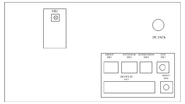
z Receiver Range Adjustment
In the middle of rear side of LT-49, you can see a rectangle compartment cover. Open
the cover, you will find a “UR” (variable Resistor) inside.
z Rear View (with Lid removed):
Turn the “UR” counter-clockwise will decrease the Receiver sensitivity and hence
shorten the range.
Turn the “UR” clockwise will increase the Receiver sensitivity and hence lengthen the
range.
10
Installation Note
z No learning process is needed at all. Just plug the power, the system is ready to use.
z Please make sure that the distance between BUN-152, RPN-99 and LT-49 is greater
than 5 meters. If the distance is not long enough, the signal reception may interfere
with each other.
z Since BUN-152, RPN-99 and LT-49 have super long communication capability, it is
possible that the coverage of each unit may be overlapped. The BUN-152 may receive
duplicated signal send from different RPN-99’s. Therefore, the PC software should
have the capability to filter out the duplicated signals.
z After the RPN-99 transmit the received signal, if it received the same signal within 10
seconds, the second signal will be ignored.
z If the LED 2 (RX LED) of RPN-99 flashes without the LED 3 (TX LED) flashing, it
means
a) The signal received is a duplicated signal in 10 seconds time-windows.
b) The system ID code is incorrect.
z To have the best receiving performance on the BUN-152, both antennas should be
installed upwards.

11
Specification Radio Frequency
1) BUN-152/RPN-99/LT-49 (900M Channels):
Frequency Hopping: Each group has a total of 25 channels.
There are 3 groups in total. Its frequency is as followed:
Group1: 906.26 ~ 914.90MHZ
Group2: 906.38 ~ 915.02MHZ
Group3: 906.50 ~ 915.14MHZ
Modulation: FM
Frequency deviation: 11.7KHZ
Data speed: 9.6K
Sensitivity: -102dBm
Band Width: 20KHZ
Channel separation: 360KHZ
Output Power: 28dBm
Frequency Tolerance: +/- 3ppm
Antenna: Dual antenna for receiver to avoid signal fading and dark spot separate
antenna for transmitter.
Communication method: full Duplex, Transmission and receiving are able to be carried
on simultaneously.
Range: Over 3 KM in open space.
2) 433.92MHZ Channel
Frequency: 433.92MHZ +/- 100KHZ
Modulation: AM (100%)
Sensitivity: -117dBm
Distance of Receiving range: 6 ~ 100 Meter (adjustable)
Communication method: Full duplex.
Federal Communication Commission Interference Statement
This equipment has been tested and found to comply with the limits for a Class B
digital device, pursuant to Part 15 of the FCC Rules. These limits are designed to
provide reasonable protection against harmful interference in a residential installation.
This equipment generates, uses and can radiate radio frequency energy and, if not
installed and used in accordance with the instructions, may cause harmful interference
to radio communications. However, there is no guarantee that interference will not
occur in a particular installation. If this equipment does cause harmful interference to
radio or television reception, which can be determined by turning the equipment off
and on, the user is encouraged to try to correct the interference by one of the
following measures:
. Reorient or relocate the receiving antenna.
. Increase the separation between the equipment and receiver.
. Connect the equipment into an outlet on a circuit different from that to which the
receiver is connected.
. Consult the dealer or an experienced radio/TV technician for help.
FCC Caution: To assure continued compliance, any changes or modifications not
expressly approved by the party responsible for compliance could void the user's
authority to operate this equipment. (Example - use only shielded interface cables
when connecting to computer or peripheral devices).
FCC Radiation Exposure Statement
This equipment complies with FCC RF radiation exposure limits set forth for an
uncontrolled environment.
This transmitter must not be co-located or operating in conjunction with any other
antenna or transmitter.